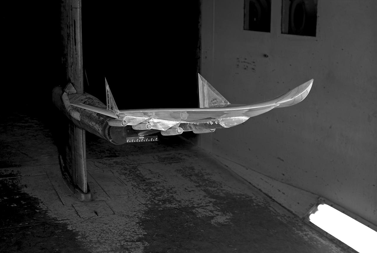
Research Model in the 7x10 High Speed Tunnel Building 1212B 300 mph tunnel
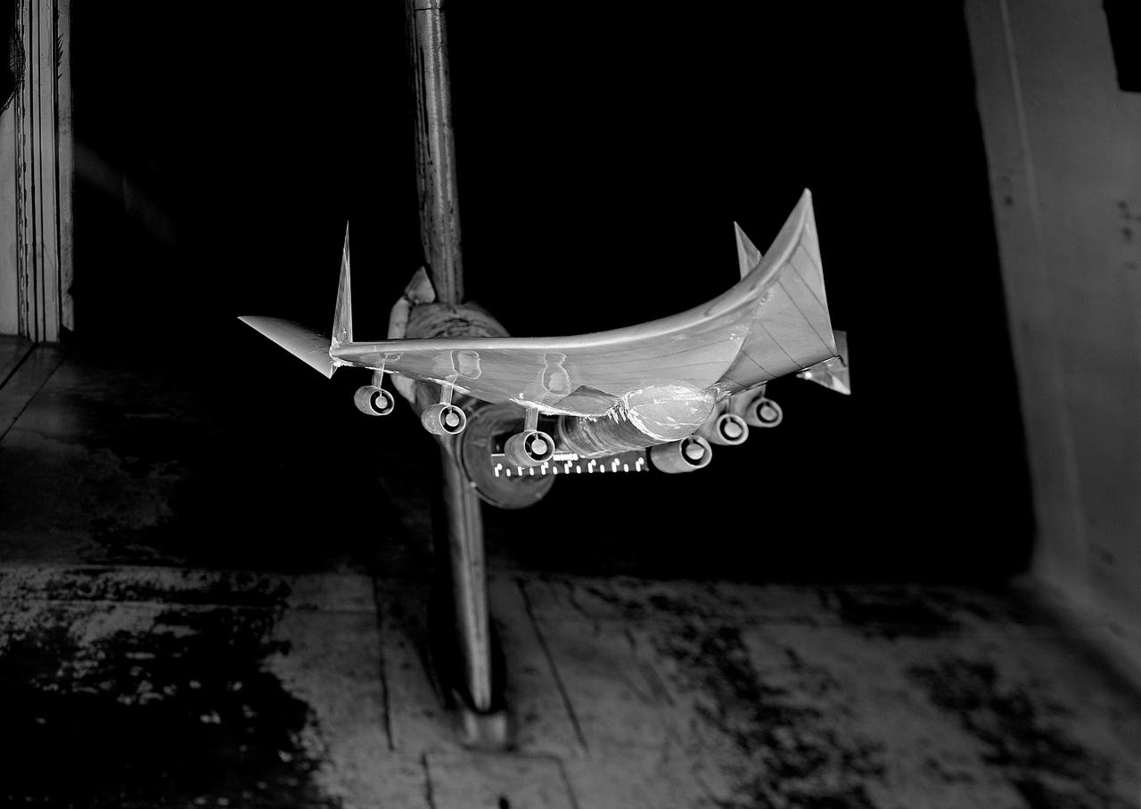
Research Model in the 7x10 High Speed Tunnel Building 1212B 300 mph tunnel
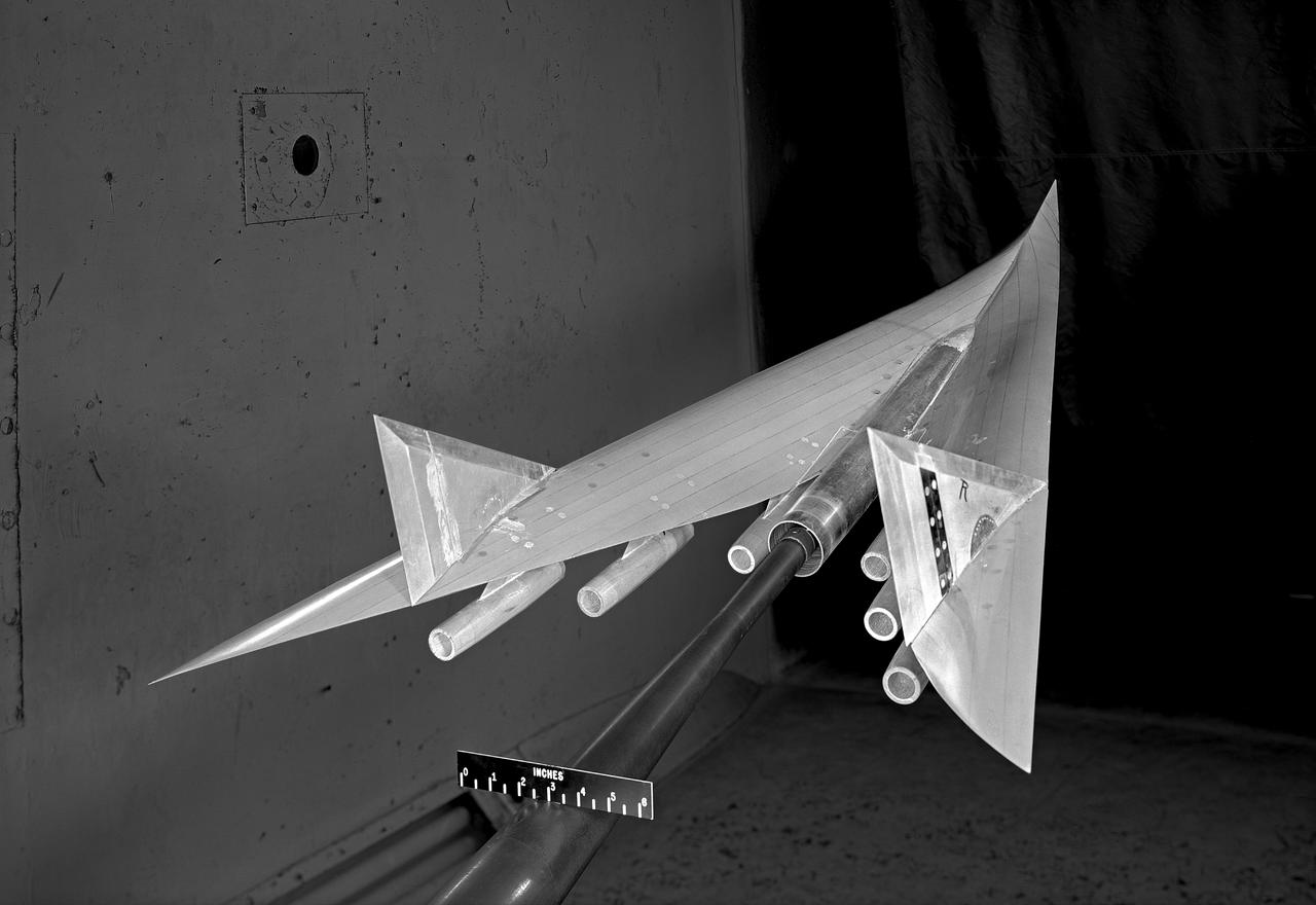
Research Model in the 7x10 High Speed Tunnel Building 1212B 300 mph tunnel
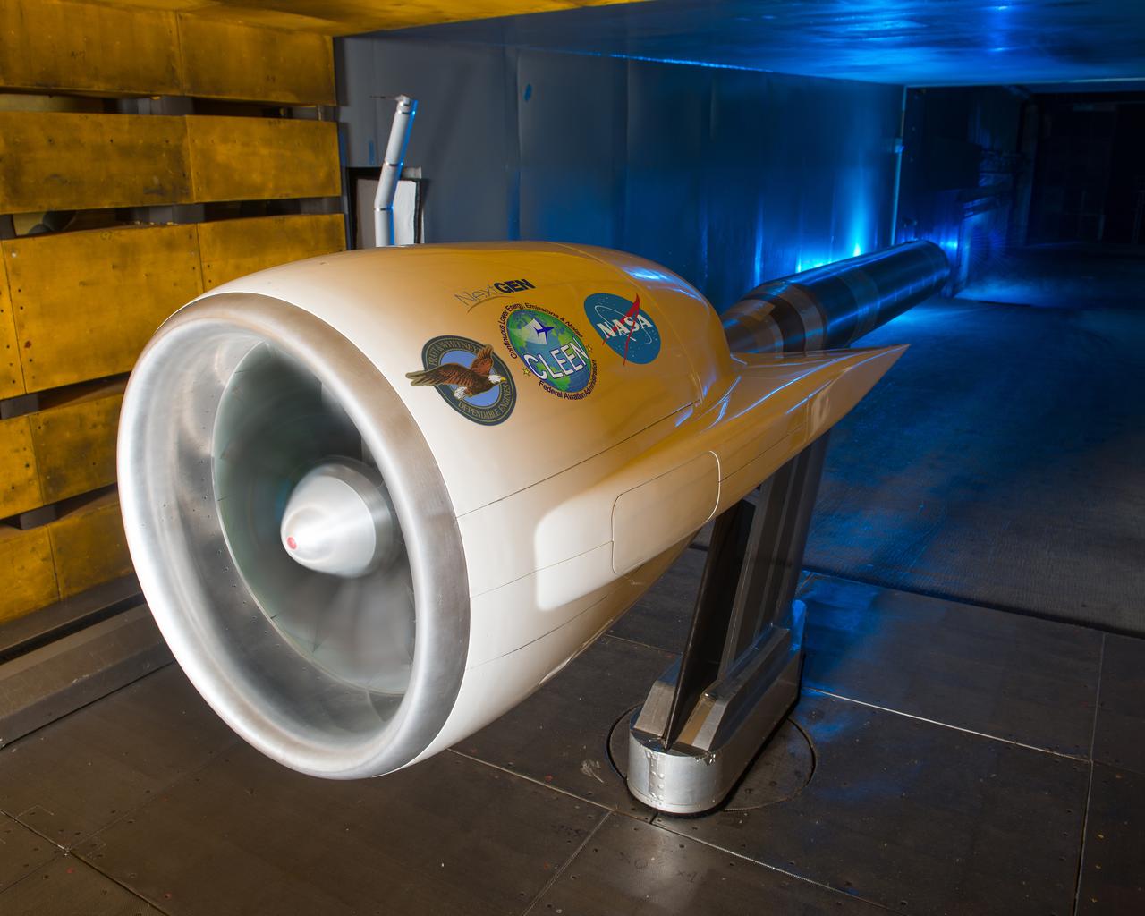
Ultra High Bypass Integrated System Test Testing of an Ultra High Bypass Ratio Turbofan model in the 9-by 15-Foot Low Speed Wind Tunnel. Pratt & Whitney designed the experimental engine to meet new efficiency and noise reduction targets for commercial aircraft set by NASA and the Federal Aviation Administration. The 9-by 15 tests analyzed two noise reduction technologies.
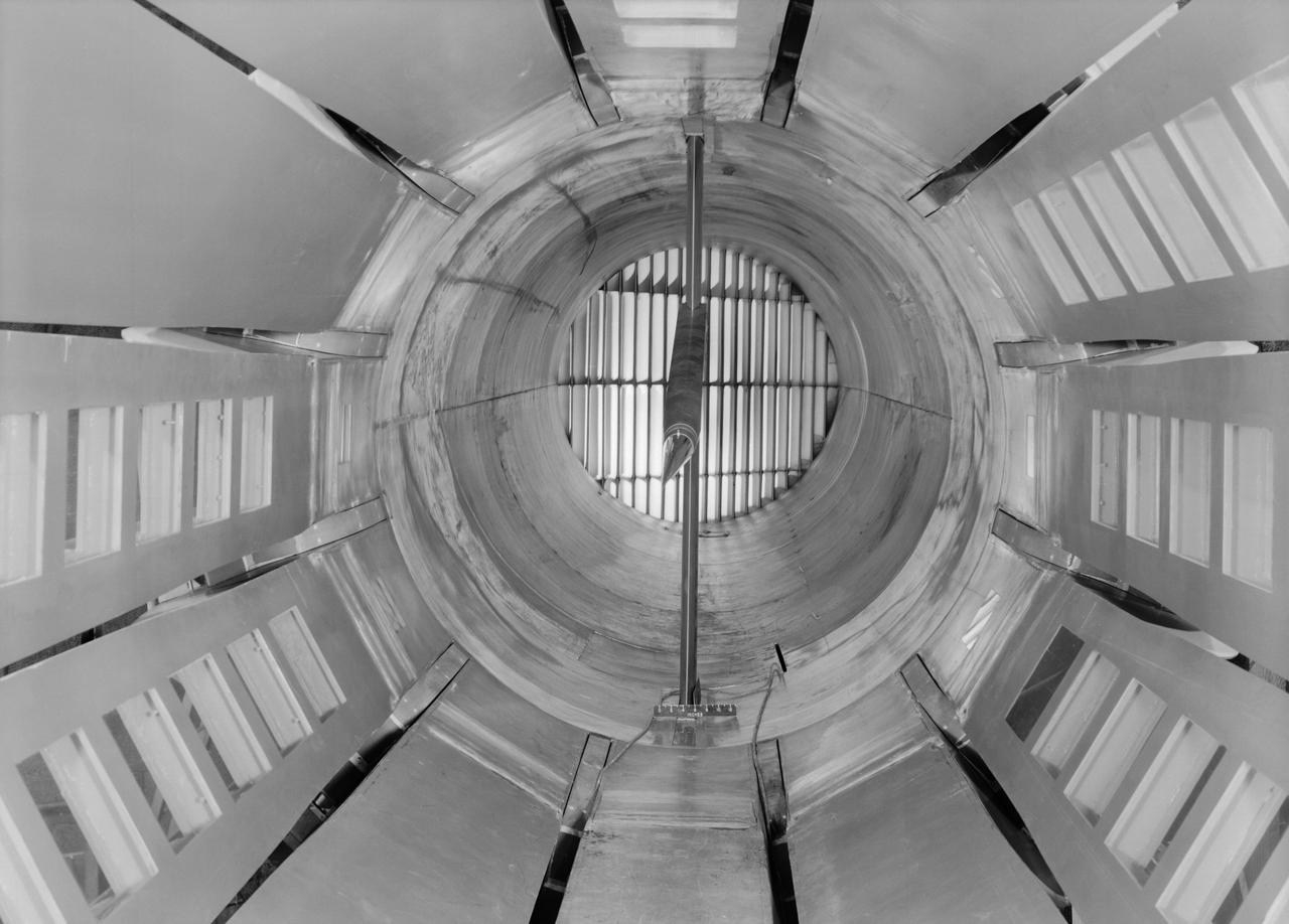
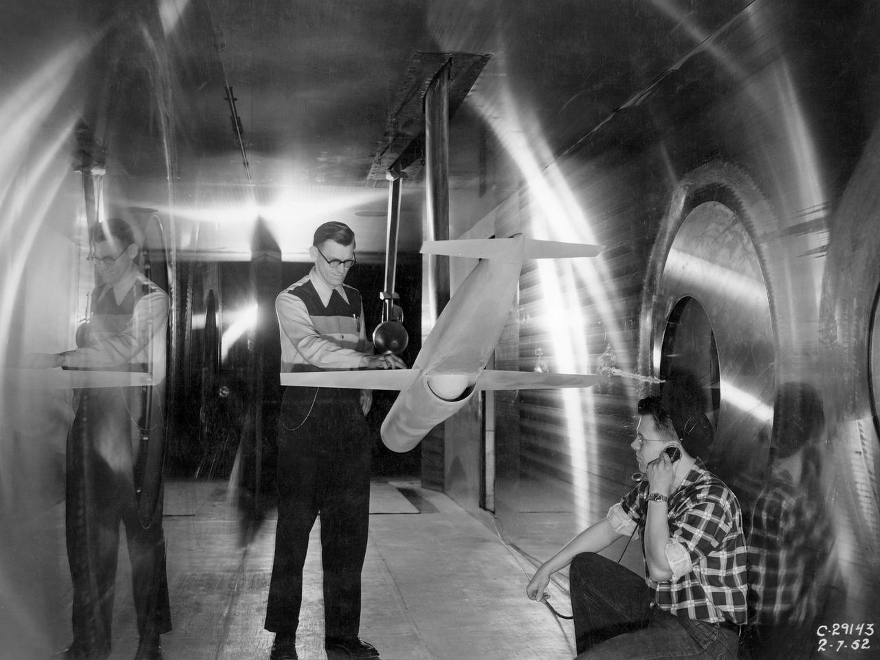
Interior view of the slotted throat test section installed in the 8-Foot High Speed Tunnel (HST) in 1950. The slotted region is about 160 inches in length. In this photograph, the sting-type model support is seen straight on. In a NASA report, the test section is described as follows: The test section of the Langley 8-foot transonic tunnel is dodecagonal in cross section and has a cross-sectional area of about 43 square feet. Longitudinal slots are located between each of the 12 wall panels to allow continuous operation through the transonic speed range. The slots contain about 11 percent of the total periphery of the test section. Six of the twelve panels have windows in them to allow for schlieren observations. The entire test section is enclosed in a hemispherical shaped chamber. John Becker noted that the tunnel s final achievement was the development and use in routine operations of the first transonic slotted throat. The investigations of wing-body shapes in this tunnel led to Whitcomb s discovery of the transonic area rule. James Hansen described the origins of the the slotted throat as follows: In 1946 Langley physicist Ray H. Wright conceived a way to do transonic research effectively in a wind tunnel by placing slots in the throat of the test section. The concept for what became known as the slotted-throat or slotted-wall tunnel came to Wright not as a solution to the chronic transonic problem, but as a way to get rid of wall interference (i.e., the mutual effect of two or more meeting waves or vibrations of any kind caused by solid boundaries) at subsonic speeds. For most of the year before Wright came up with this idea, he had been trying to develop a theoretical understanding of wall interference in the 8-Foot HST, which was then being repowered for Mach 1 capability. When Wright presented these ideas to John Stack, the response was enthusiastic but neither Wright nor Stack thought of slotted-throats as a solution to the transonic problem, only the wall interference problem. It was an accidental discovery which showed that slotted throats might solve the transonic problem. Most engineers were skeptical but Stack persisted. Initially, plans were to modify the 16-Foot tunnel but in the spring of 1948, Stack announced that the 8-Foot HST would also be modified. As Hansen notes: The 8-Foot HST began regular transonic operations for research purposes on 6 October 1950. The concept was a success and led to plans for a new wind tunnel which would be known as the 8-Foot Transonic Pressure Tunnel. -- Published in U.S., National Advisory Committee for Aeronautics, Characteristics of Nine Research Wind Tunnels of the Langley Aeronautical Laboratory, 1957, pp. 17, 22 James R. Hansen, Engineer in Charge, NASA SP-4305, p. 454 and Chapter 11, The Slotted Tunnel and the Area Rule.

UNSTART PROGRAM - 10X10 FOOT SUPERSONIC WIND TUNNEL AS PART OF THE HIGH SPEED RESEARCH PROGRAM
UNSTART PROGRAM - 10X10 FOOT SUPERSONIC WIND TUNNEL AS PART OF THE HIGH SPEED RESEARCH PROGRAM
NACA Photographer - 16ft High Speed Wind Tunnel downstream view through cooling tower section

UNSTART PROGRAM - 10X10 FOOT SUPERSONIC WIND TUNNEL AS PART OF THE HIGH SPEED RESEARCH PROGRAM

UNSTART PROGRAM - 10X10 FOOT SUPERSONIC WIND TUNNEL AS PART OF THE HIGH SPEED RESEARCH PROGRAM
UNSTART PROGRAM - 10X10 FOOT SUPERSONIC WIND TUNNEL AS PART OF THE HIGH SPEED RESEARCH PROGRAM
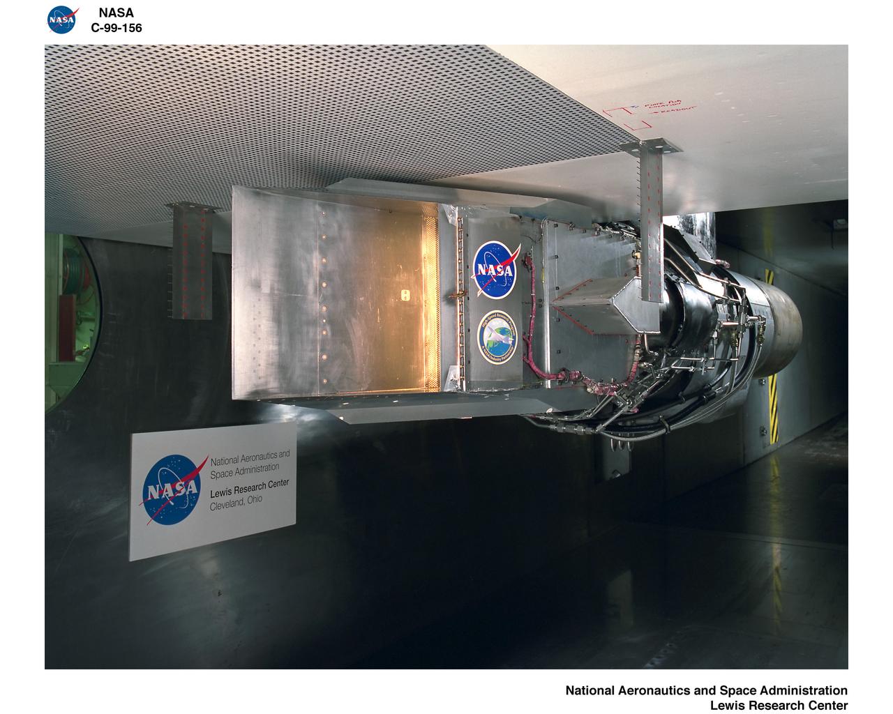
UNSTART PROGRAM - 10X10 FOOT SUPERSONIC WIND TUNNEL AS PART OF THE HIGH SPEED RESEARCH PROGRAM
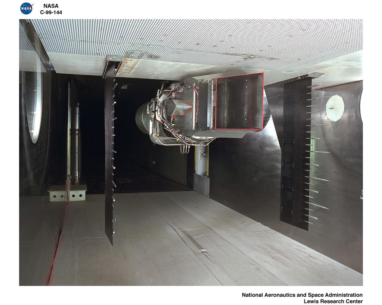
UNSTART PROGRAM - 10X10 FOOT SUPERSONIC WIND TUNNEL AS PART OF THE HIGH SPEED RESEARCH PROGRAM
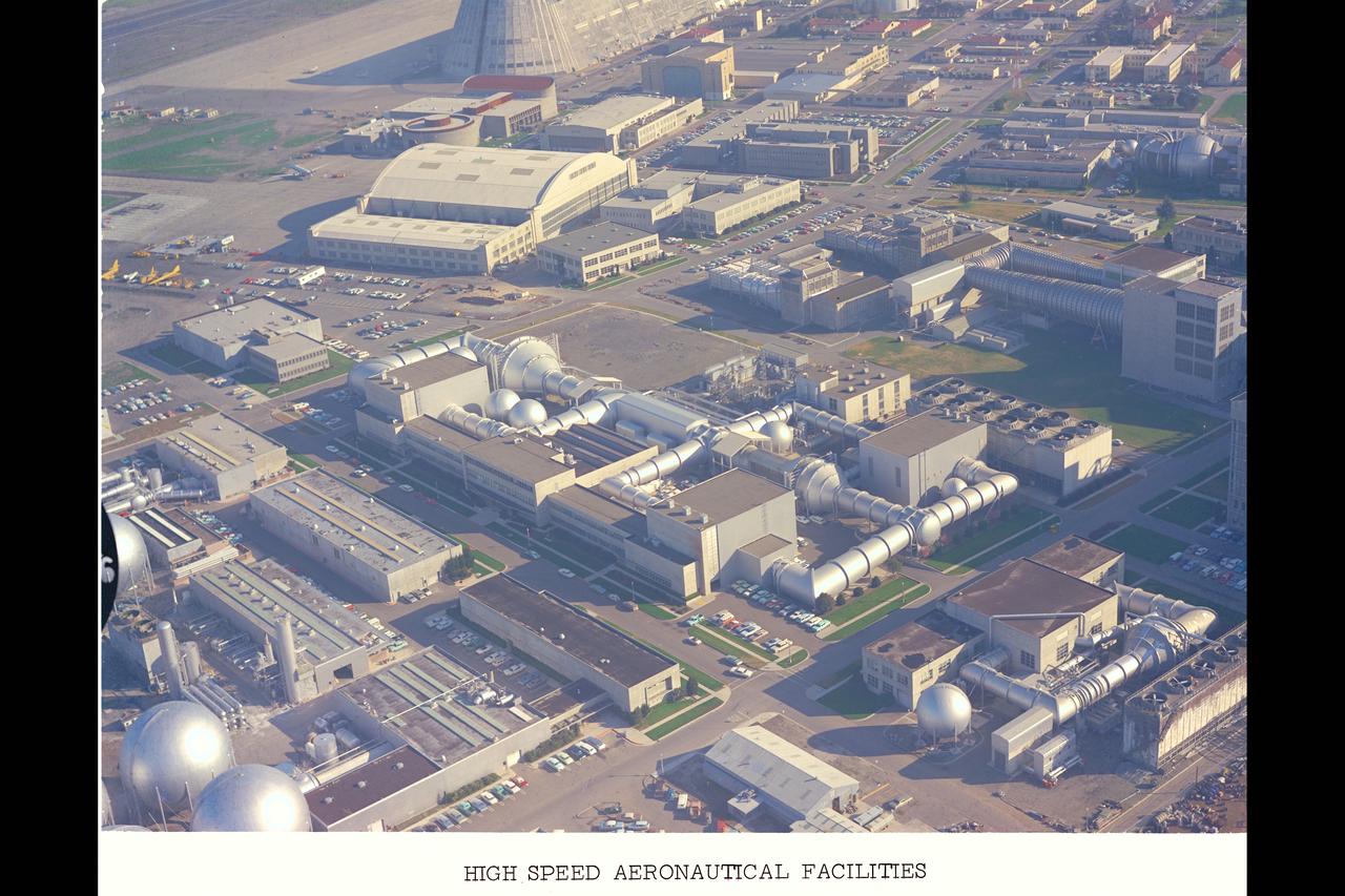
Aerial Survey of Ames Research Center centered on the Unitary Plan Wind Tunnel Complex and High Speed Aerodynamic Facilities (used in Bicentennial)
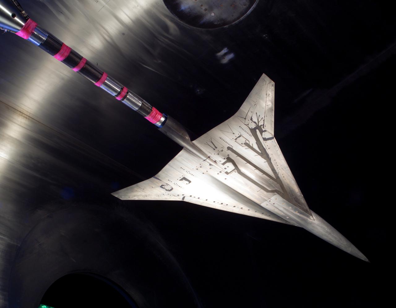
NASA Glenn/NASA Langley, Loads Comparison Test With 6 Component Force/Moment Balance and 1.7% High Speed Research, HSR Model 5. In the Glenn Research Center 10x10 Foot Supersonic Wind Tunnel, SWT
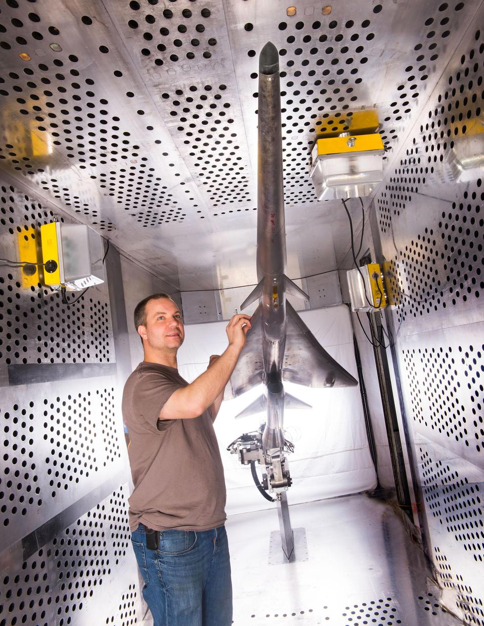
Mechanical technician Dan Pitts prepares a scale model of Lockheed Martin's Quiet Supersonic Technology (QueSST) X-plane preliminary design for its first high-speed wind tunnel tests at NASA's Glenn Research Center.
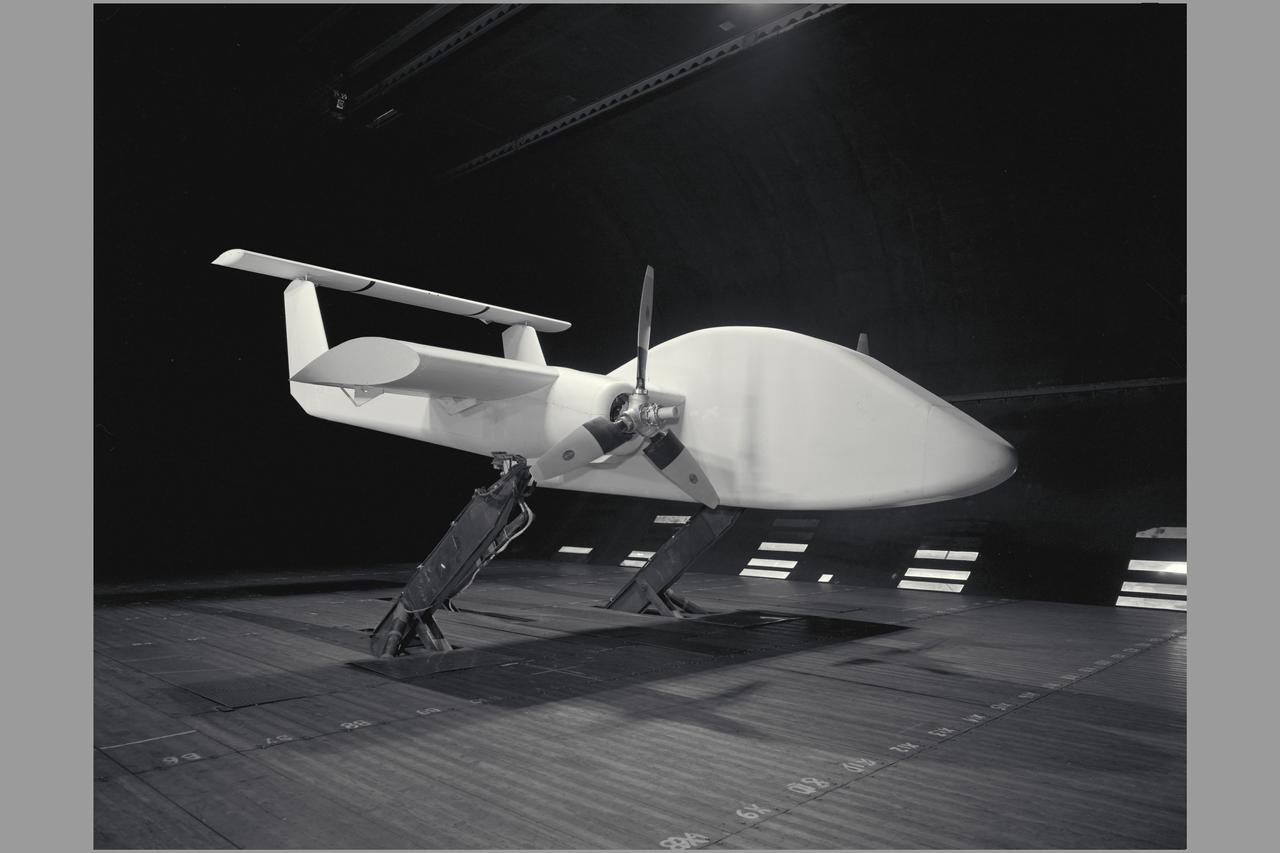
3/4 front view of model with flaps up. V/STOL Aircraft: Wind tunnel investigation of rotating cylinder applied to training edge flaps for high lift & low-speed control.
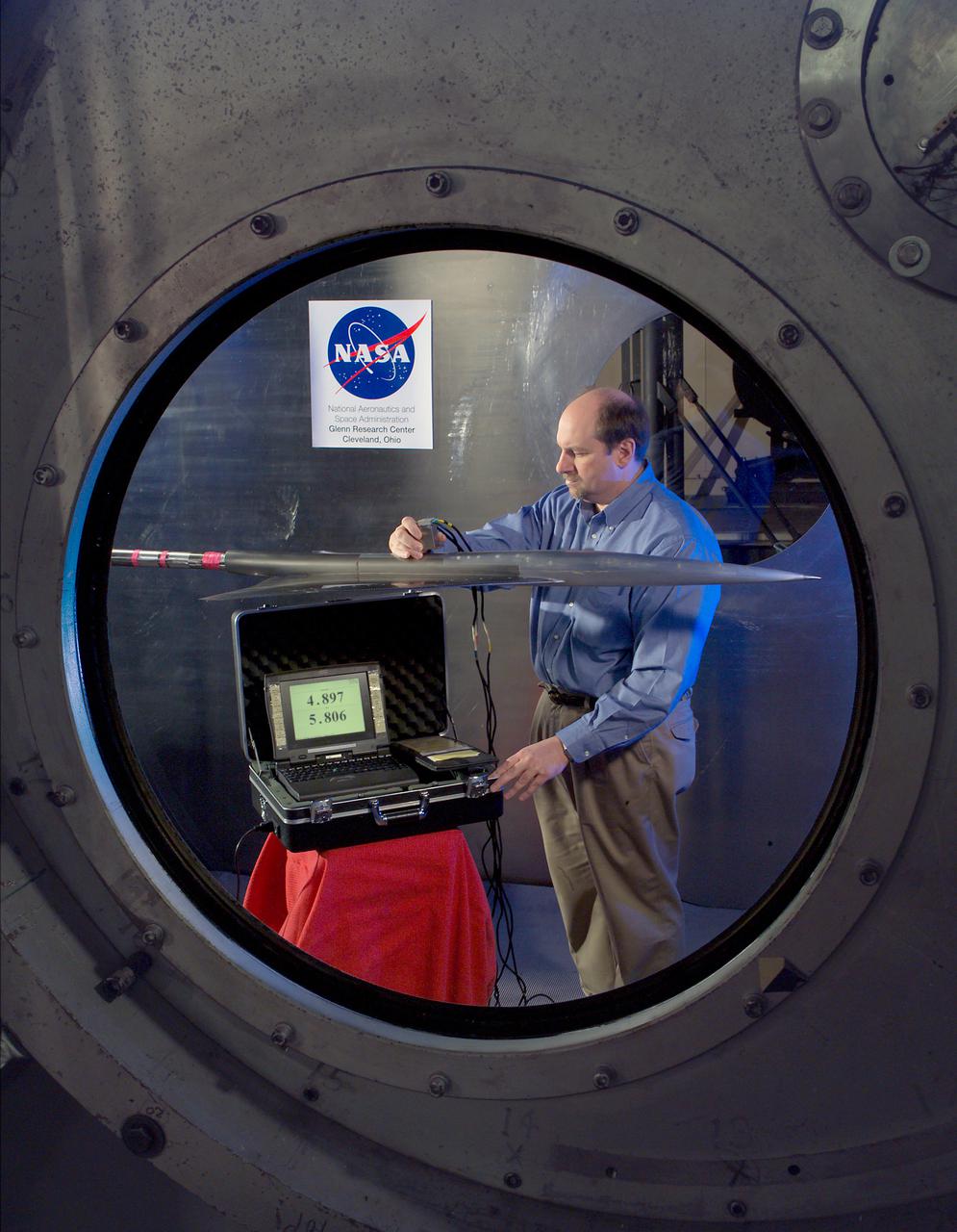
NASA GLENN/NASA LANGLEY LOADS COMPARISON TEST WITH 6 COMPONENT FORCE/MOMENT BALANCE AND 1.7% HIGH SPEED RESEARCH MODEL 5. in the 10x10 super sonic wind tunnel
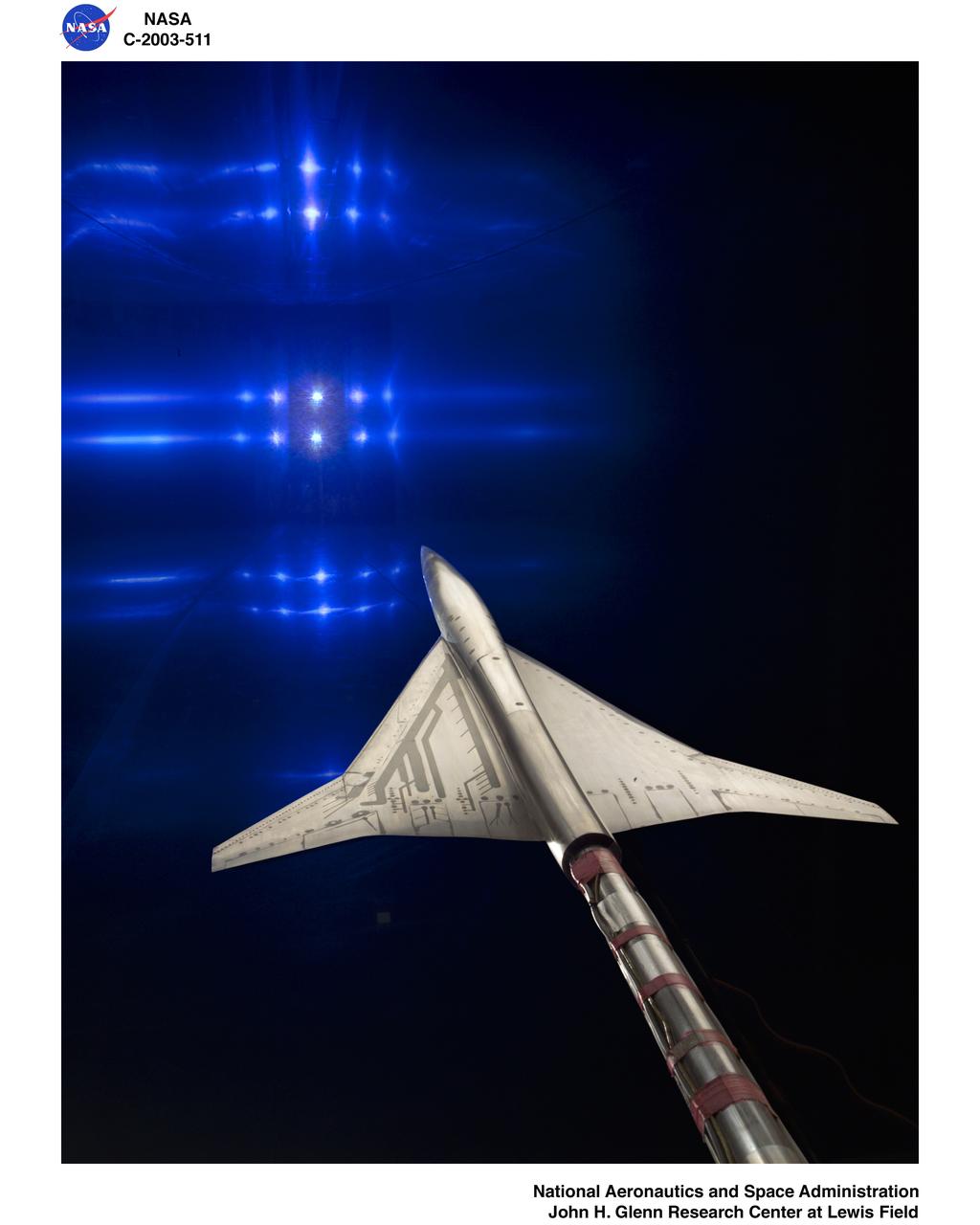
NASA GLENN/NASA LANGLEY LOADS COMPARISON TEST WITH 6 COMPONENT FORCE/MOMENT BALANCE AND 1.7% HIGH SPEED RESEARCH MODEL 5.l in the 10x10 supersonic wind tunnel
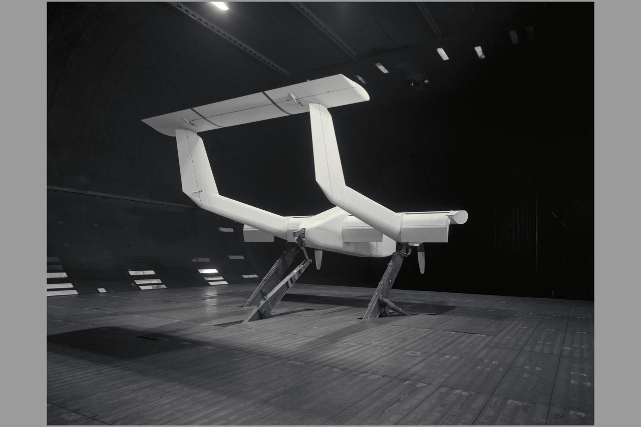
3/4 rear view of model with flaps down. V/STOL Aircraft: Wind tunnel investigation of rotating cylinder applied to training edge flaps for high lift & low-speed control.

3/4 rear view of model with flaps down with Cecil E. MacDonald. V/STOL Aircraft: Wind tunnel investigation of rotating cylinder applied to training edge flaps for high lift & low-speed control.
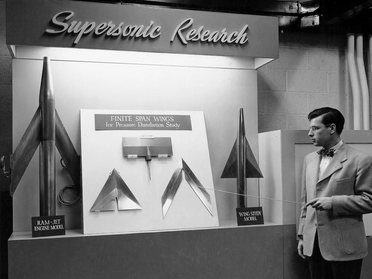
On March 22, 1946, 250 members of the Institute of Aeronautical Science toured the NACA’s Aircraft Engine Research Laboratory. NACA Chairman Jerome Hunsaker and Secretary John Victory were on hand to brief the attendees in the Administration Building before the visited the lab’s test facilities. At each of the twelve stops, researchers provided brief presentations on their work. Topics included axial flow combustors, materials for turbine blades, engine cooling, icing prevention, and supersonic flight. The laboratory reorganized itself in October 1945 as World War II came to an end to address newly emerging technologies such as the jet engine, rockets, and high-speed flight. While design work began on what would eventually become the 8- by 6-Foot Supersonic Wind Tunnel, NACA Lewis quickly built several small supersonic tunnels. These small facilities utilized the Altitude Wind Tunnel’s massive air handling equipment to generate high-speed airflow. The display seen in this photograph was set up in the building that housed the first of these wind tunnels. Eventually the building would contain three small supersonic tunnels, referred to as the “stack tunnels” because of the vertical alignment. The two other tunnels were added to this structure in 1949 and 1951. The small tunnels were used until the early 1960s to study the aerodynamic characteristics of supersonic inlets and exits.
An engineer at the Marshall Space Flight Center (MSFC) observes a model of the Space Shuttle Orbiter being tested in the MSFC's 14x14-Inch Trisonic Wind Tunnel. The 14-Inch Wind Tunnel is a trisonic wind tunnel. This means it is capable of running subsonic, below the speed of sound; transonic, at or near the speed of sound (Mach 1,760 miles per hour at sea level); or supersonic, greater than Mach 1 up to Mach 5. It is an intermittent blowdown tunnel that operates by high pressure air flowing from storage to either vacuum or atmospheric conditions. The MSFC 14x14-Inch Trisonic Wind Tunnel has been an integral part of the development of the United States space program Rocket and launch vehicles from the Jupiter-C in 1958, through the Saturn family up to the current Space Shuttle and beyond have been tested in this Wind Tunnel. MSFC's 14x14-Inch Trisonic Wind Tunnel, as with most other wind tunnels, is named after the size of the test section. The 14-Inch Wind Tunnel, as in the past, will continue to play a large but unseen role in the development of America's space program.
This photograph shows an overall view of the Marshall Space Flight Center's (MSFC's) 14x14-Inch Trisonic Wind Tunnel. The 14-Inch Wind Tunnel is a trisonic wind tunnel. This means it is capable of running subsonic, below the speed of sound; transonic, at or near the speed of sound (Mach 1, 760 miles per hour at sea level); or supersonic, greater than Mach 1 up to Mach 5. It is an intermittent blowdown tunnel that operates by high pressure air flowing from storage to either vacuum or atmospheric conditions. The MSFC 14x14-Inch Trisonic Wind Tunnel has been an integral part of the development of the United States space program Rocket and launch vehicles from the Jupiter-C in 1958, through the Saturn family up to the current Space Shuttle and beyond have been tested in this Wind Tunnel. MSFC's 14x14-Inch Trisonic Wind Tunnel, as with most other wind tunnels, is named after the size of the test section. The 14-Inch Wind Tunnel, as in the past, will continue to play a large but unseen role in the development of America's space program.
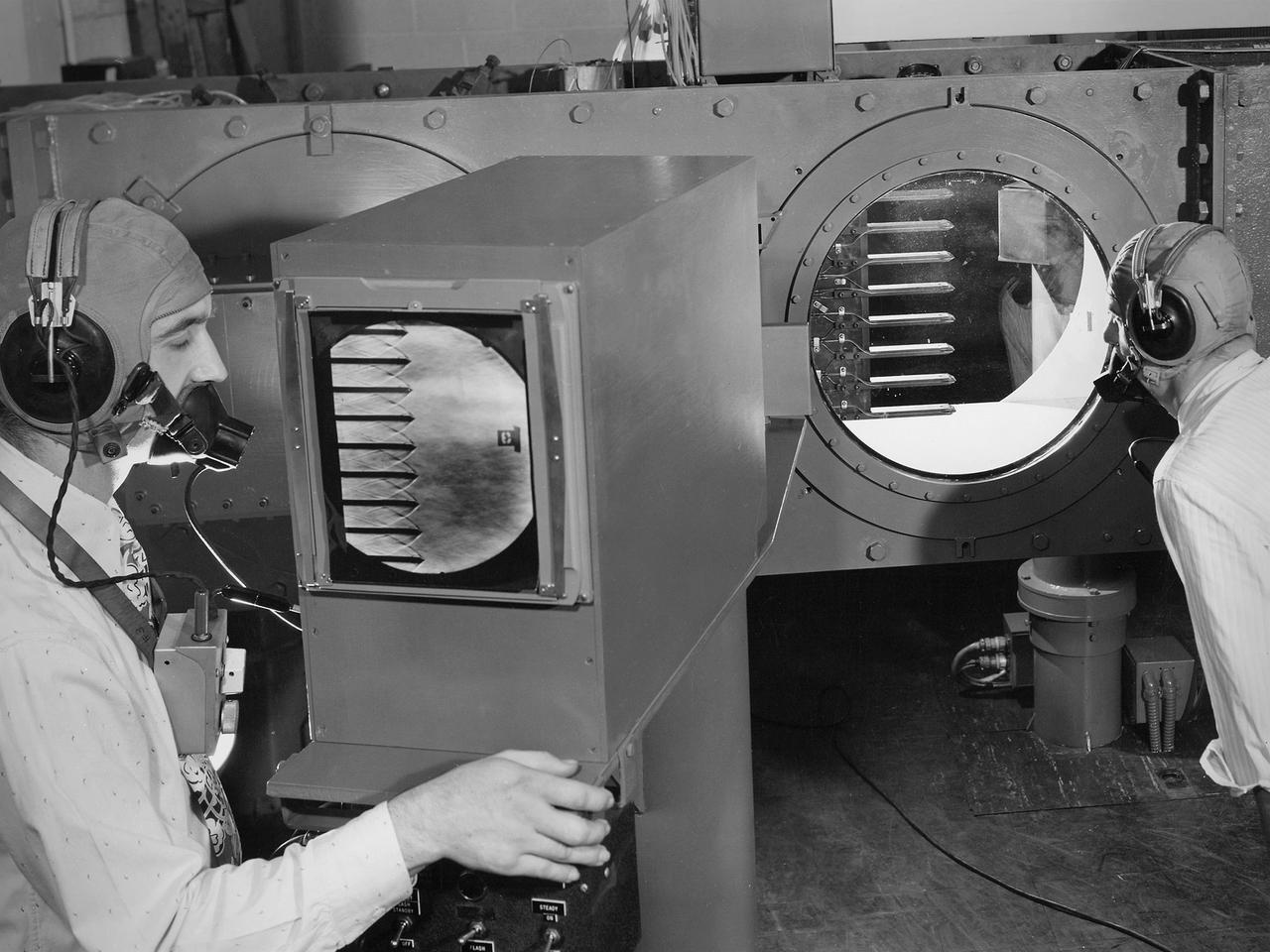
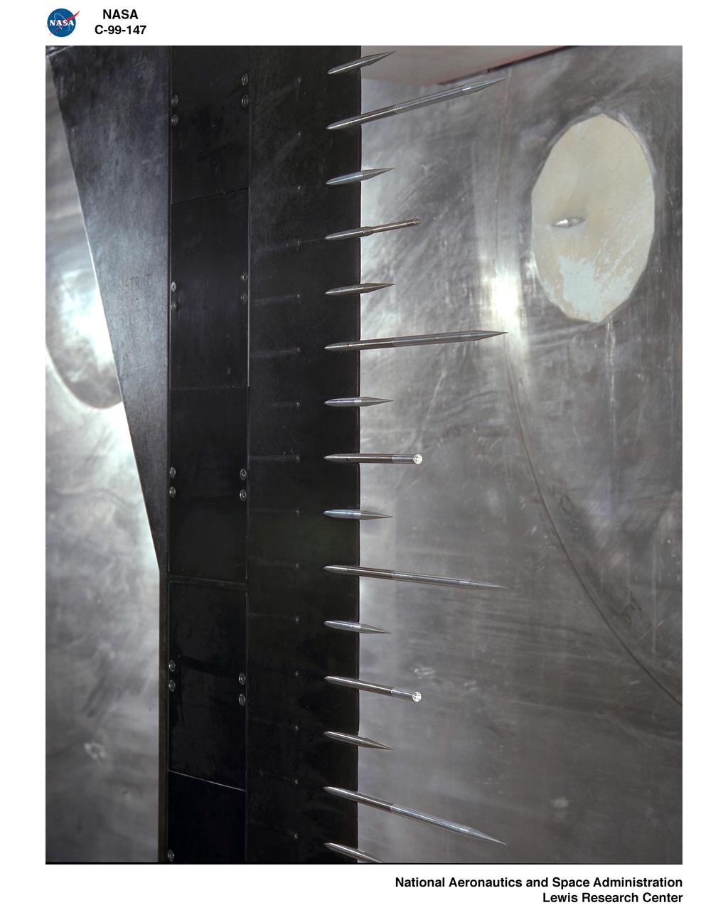
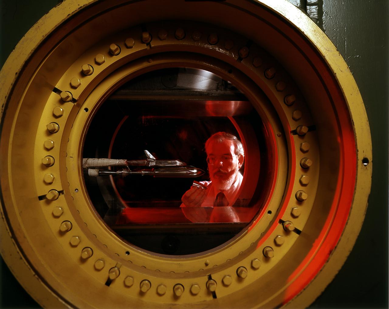
Engineers calibrate one of three small supersonic wind tunnels that were collectively referred to as the “Stack Tunnels” at the National Advisory Committee for Aeronautics (NACA) Lewis Flight Propulsion Laboratory. In late 1945 NACA Lewis reorganized its staff and began constructing a new wave of facilities to address high-speed flight and the turbojet and rocket technologies that emerged during World War II. While design work began on what would eventually become the 8- by 6-Foot Supersonic Wind Tunnel, NACA Lewis quickly built several small supersonic tunnels. These small facilities utilized the Altitude Wind Tunnel’s massive air handling equipment. Three of the small tunnels were built vertically on top of each other and thus were known as the Stack Tunnels. The first of the Stack Tunnels was an 18- by 18-inch tunnel that began operating in August 1945 at speeds up to Mach 1.91. The second tunnel, whose 24- by 24-inch test section is shown here, was added in 1949. It could generate air flows up to Mach 3.96. A third tunnel with an 18- by 18-inch test section began operating in 1951 with speeds up to Mach 3.05. The small tunnels were used until the early 1960s to study the aerodynamic characteristics of supersonic inlets and exits. The technician to the left in this photograph is operating a Schlieren camera to view the air flow dynamics inside the 24- by 24-inch test section. The technician on the right is viewing the pronged test article through the circular window. They are calibrating the tunnel and its equipment to prepare for the initial test runs.
Construction workers install the drive motor for the Altitude Wind Tunnel (AWT) in the Exhauster Building at the National Advisory Committee for Aeronautics (NACA) Aircraft Engine Research Laboratory. The AWT was capable of operating full-scale engines in air density, speed, and temperature similar to that found at high altitudes. The tunnel could produce wind speeds up to 500 miles per hour through a 20-foot-diameter test section at the standard operating altitude of 30,000 feet. The airflow was created by a large wooden fan near the tunnel’s southeast corner. This photograph shows the installation of the 18,000-horsepower drive motor inside the adjoining Exhauster Building in July 1943. The General Electric motor, whose support frame is seen in this photograph, connected to a drive shaft that extended from the building, through the tunnel shell, and into a 12-bladed, 31-foot-diameter spruce wood fan. Flexible couplings on the shaft allowed for the movement of the shell. The corner of the Exhauster Building was built around the motor after its installation. The General Electric induction motor could produce 10 to 410 revolutions per minute and create wind speeds up to 500 miles per hour, or Mach 0.63, at 30,000 feet. The AWT became operational in January 1944 and tested piston, turbojet and ramjet engines for nearly 20 years.
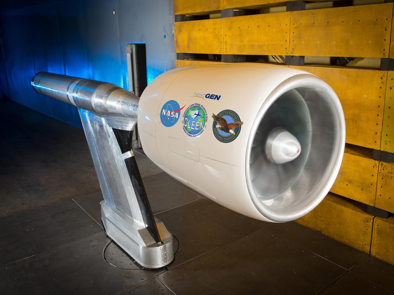
NASA’s Environmentally Responsible Aviation Project, in collaboration with the Federal Aviation Administration (FAA) and Pratt & Whitney, completed testing of an Ultra High Bypass Ratio Turbofan Model in the 9’ x 15’ Low Speed Wind Tunnel at NASA Glenn Research Center. The fan model is representative of the next generation of efficient and quiet Ultra High Bypass Ratio Turbofan Engine designs.

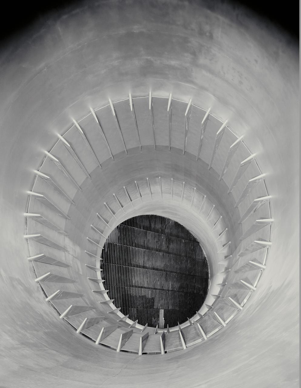
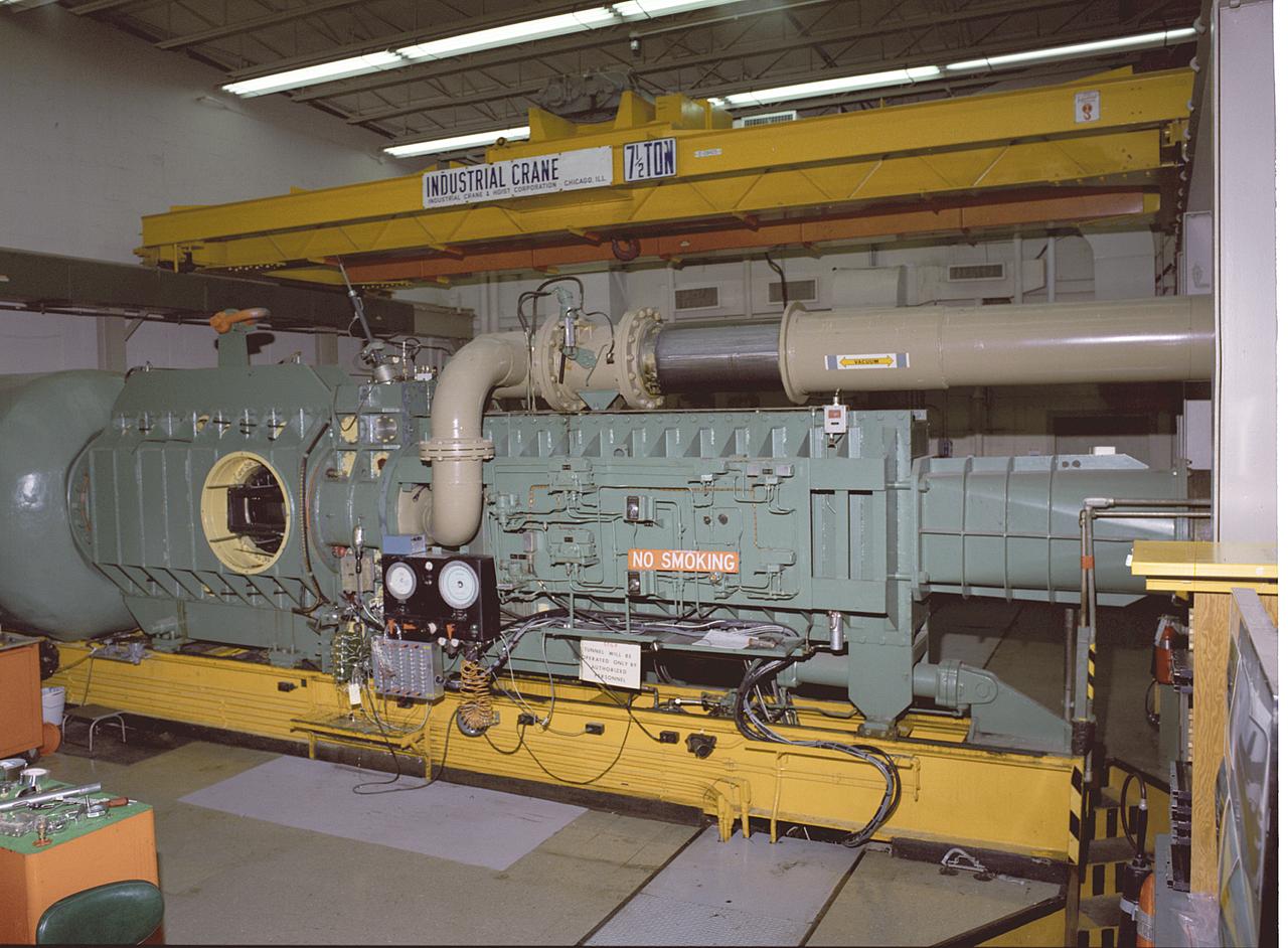
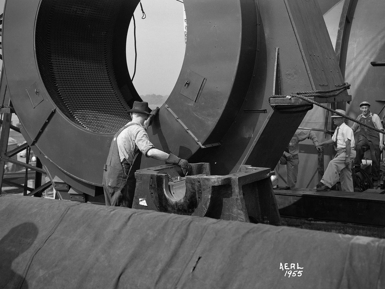
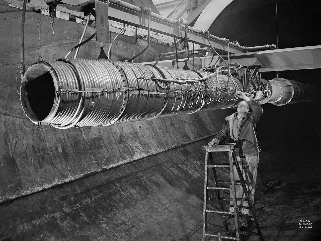
A technician at the National Advisory Committee for Aeronautics (NACA) Lewis Flight Propulsion Laboratory examines one of the massive axial-flow compressor stages that created the high-speed air flow through the 8- by 6-Foot Supersonic Wind Tunnel. The tunnel’s first run was on April 3, 1949, just over a week before this photograph was taken. The 8- by 6 was the laboratory’s first large supersonic wind tunnel and the NACA’s largest supersonic tunnel at the time. The 8- by 6-foot tunnel was originally an open-throat non-return tunnel. The supersonic air flow was blown through the tubular facility and expelled out the other end into the atmosphere with a roar. Complaints from the local community led to the addition of a muffler at the tunnel exit in 1956 and the eventual addition of a return leg. The return leg allowed the tunnel to be operated as either an open system with large doors venting directly to the atmosphere for propulsion system tests or as a closed loop for aerodynamic tests. The air flow was generated by a large seven-stage axial-flow compressor, seen in this photograph, that was powered by three electric motors with a combined 87,000 horsepower. The system required 36,000 kilowatts of power per hour to generate wind velocities of Mach 1.5, and 72,000 kilowatts per hour for Mach 2.0.
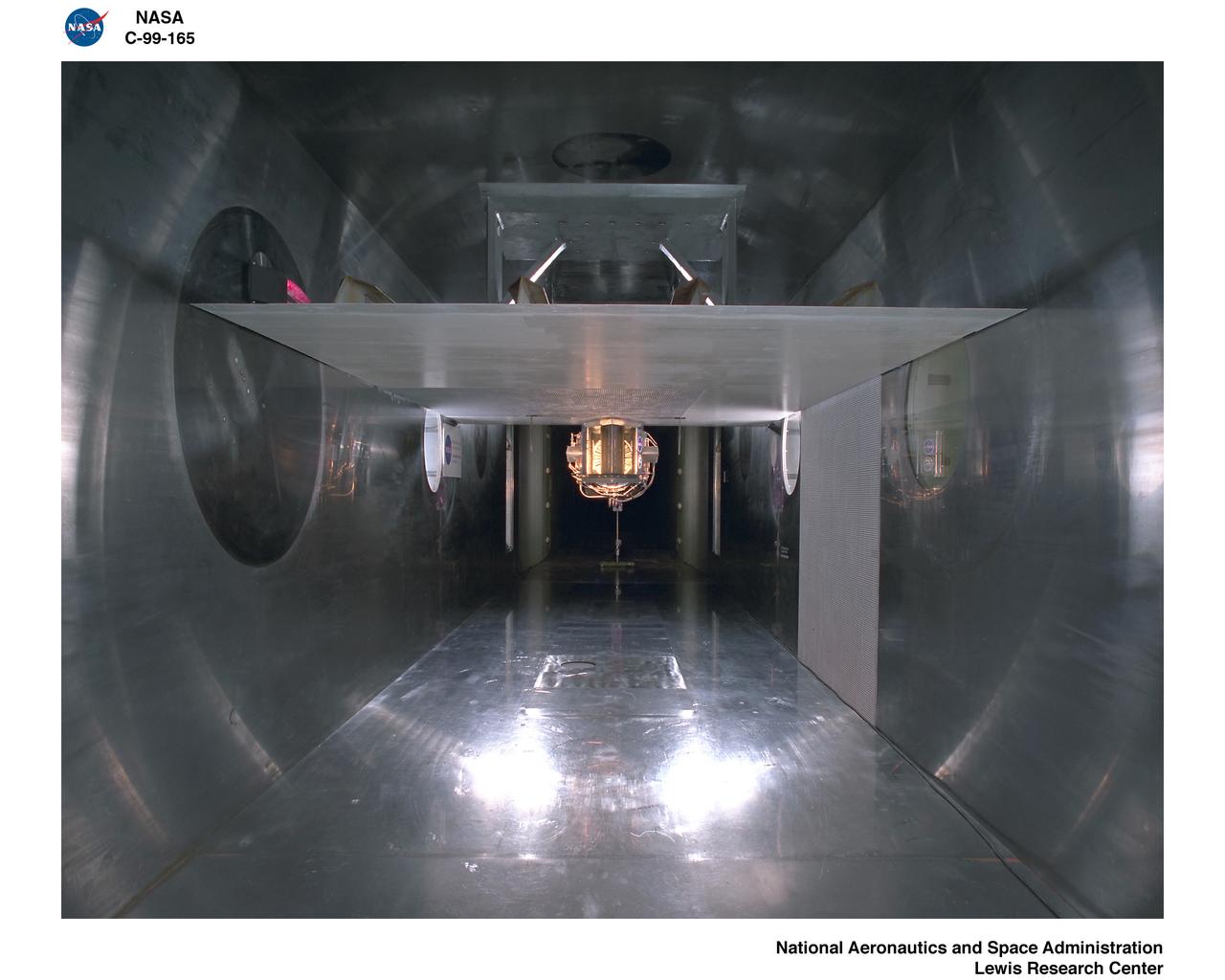
A researcher at the National Advisory Committee for Aeronautics (NACA) Lewis Flight Propulsion Laboratory checks the setup of a RJM-2 ramjet model in the test section of the 8- by 6-Foot Supersonic Wind Tunnel. The 8- by 6 was not only the laboratory’s first large supersonic wind tunnel, but it was also the NACA’s first facility capable of testing an operating engine at supersonic speeds. The 8- by 6-foot tunnel has been used to study engine inlets, fuel injectors, flameholders, exit nozzles, and controls on ramjet and turbojet propulsion systems. The 8-foot wide and 6-foot tall test section consisted of 1-inch thick steel plates with hatches on the floor and ceiling to facilitate the installation of the test article. The two windows seen on the right wall allowed photographic equipment to be set up. The test section was modified in 1956 to accommodate transonic research. NACA engineers drilled 4,700 holes into the test section walls to reduce transonic pressure disturbances and shock waves. NACA Lewis undertook an extensive research program on ramjets in the 1940s using several of its facilities. Ramjets provide a very simple source of propulsion. They are basically a tube which ingests high speed air, ignites it, and then expels the heated air at a significantly higher velocity. Ramjets are extremely efficient and powerful but can only operate at high speeds. Therefore, they require a booster rocket or aircraft drop to accelerate them to high speeds before they can operate.

National Aeronautics and Space Administration (NASA) researcher John Carpenter inspects an aircraft model with a four-fan thrust reverser which would be studied in the 9- by 15-Foot Low Speed Wind Tunnel at the Lewis Research Center. Thrust reversers were introduced in the 1950s as a means for slowing high-speed jet aircraft during landing. Engineers sought to apply the technology to Vertical and Short Takeoff and Landing (VSTOL) aircraft in the 1970s. The new designs would have to take into account shorter landing areas, noise levels, and decreased thrust levels. A balance was needed between the thrust reverser’s efficiency, its noise generation, and the engine’s power setting. This model underwent a series of four tests in the 9- by 15-foot tunnel during April and May 1974. The model, with a high-wing configuration and no tail, was equipped with four thrust-reverser engines. The investigations included static internal aerodynamic tests on a single fan/reverser, wind tunnel isolated fan/reverser thrust tests, installation effects on a four-fan airplane model in a wind tunnel, and single reverser acoustic tests. The 9-by 15 was built inside the return leg of the 8- by 6-Foot Supersonic Wind Tunnel in 1968. The facility generates airspeeds from 0 to 175 miles per hour to evaluate the aerodynamic performance and acoustic characteristics of nozzles, inlets, and propellers, and investigate hot gas re-ingestion of advanced VSTOL concepts. John Carpenter was a technician in the Wind Tunnels Service Section of the Test Installations Division.
A 20-inch diameter ramjet installed in the Altitude Wind Tunnel at the National Advisory Committee for Aeronautics (NACA) Lewis Flight Propulsion Laboratory. The Altitude Wind Tunnel was used in the 1940s to study early ramjet configurations. Ramjets provide a very simple source of propulsion. They are basically a tube which takes in high-velocity air, ignites it, and then expels the expanded airflow at a significantly higher velocity for thrust. Ramjets are extremely efficient and powerful but can only operate at high speeds. Therefore a turbojet or rocket was needed to launch the vehicle. This NACA-designed 20-inch diameter ramjet was installed in the Altitude Wind Tunnel in May 1945. The ramjet was mounted under a section of wing in the 20-foot diameter test section with conditioned airflow ducted directly to the engine. The mechanic in this photograph was installing instrumentation devices that led to the control room. NACA researchers investigated the ramjet’s overall performance at simulated altitudes up to 47,000 feet. Thrust measurements from these runs were studied in conjunction with drag data obtained during small-scale studies in the laboratory’s small supersonic tunnels. An afterburner was attached to the ramjet during the portions of the test program. The researchers found that an increase in altitude caused a reduction in the engine’s horsepower. They also determined the optimal configurations for the flameholders, which provided the engine’s ignition source.
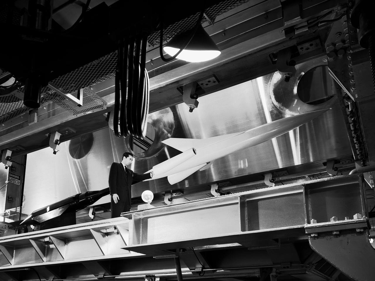
A researcher examines a model being installed in the test section of the 10- by 10-Foot Supersonic Wind Tunnel during the 1957 Inspection of the National Advisory Committee for Aeronautics (NACA) Lewis Flight Propulsion Laboratory. The NACA held its annual Inspection at one of its three research laboratories. Representatives from the military, aeronautical industry, universities, and the press were invited to the laboratory to be briefed on the NACA’s latest research efforts and tour the state- of- the- art test facilities. Over 1700 people visited the NACA Lewis in Cleveland, Ohio during the October 7 - 10, 1957 Inspection. NACA researchers Leonard Obery, seen here, James Connors, Leonard, Stitt, David Bowditch gave presentations on high Mach number turbojets at the 10- by 10 tunnel. It had been only 15 years since a jet aircraft had first flown in the US. Since then the sound barrier had been broken and speeds of Mach 2.5 had been achieved. In the late 1950s NACA researchers sought to create an engine that could achieve Mach 4. This type of engine would require an extremely long inlet and nozzle which would have to be capable of adjusting their diameter for different speeds. A Mach 4 engine would require new composite materials to withstand the severe conditions, modified airframes to hold the longer engines, and high temperature seals and lubricants. The 10- by 10-foot tunnel, which had only been in operation for a year and a half, would play a critical role in these studies. NACA researchers at other facilities discussed high energy aircraft fuels and rocket propellants, aircraft noise reduction, hypersonic flight, nuclear propulsion, and high temperature materials.
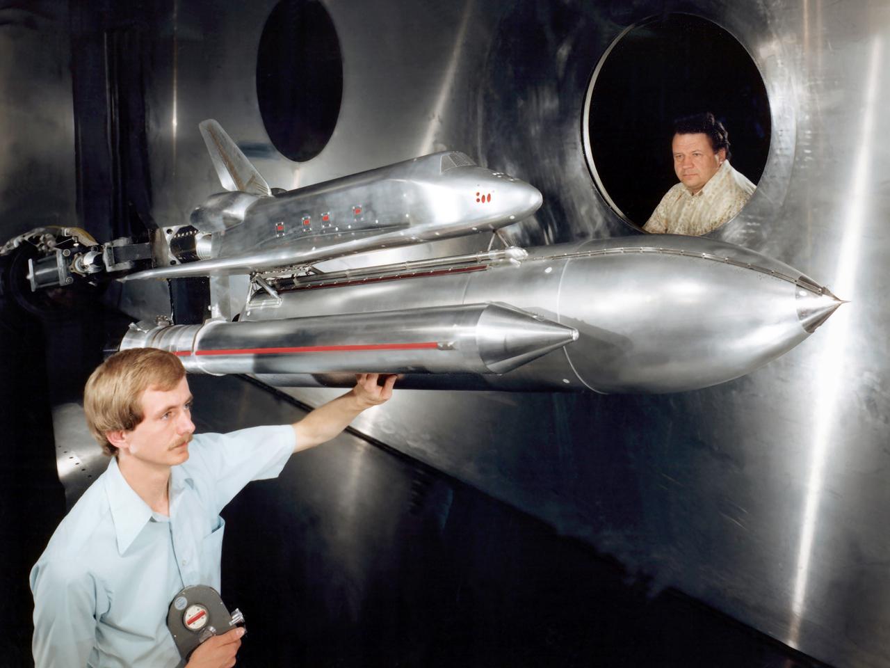
Technicians examine a scale model of the space shuttle used to obtain pressure data during tests in the 10- by 10-Foot Supersonic Wind Tunnel at the National Aeronautics and Space Administration (NASA) Lewis Research Center. Lewis researchers used the 10- by 10 tunnel extensively in the 1970s to study shuttle configurations in order to forecast conditions during an actual flight. These tests included analysis of the solid rocket boosters’ aerodynamics, orbiter forebody angle -of -attack and air speed, base heating for entire shuttle, and engine-out loads. The test seen in this photograph used a 3.5- percent scale aluminum alloy model of the entire launch configuration. The program was designed to obtain aerodynamic pressure data. The tests were part of a larger program to study possible trouble areas for the shuttle’s new Advanced Flexible Reusable Surface Insulation. The researchers obtained aeroacoustic data and pressure distributions from five locations on the model. Over 100 high-temperature pressure transducers were attached to the model. Other portions of the test program were conducted at Lewis’ 8- by 6-Foot Supersonic Wind Tunnel and the 11- by 11-Foot Transonic Wind Tunnel at Ames Research Center.
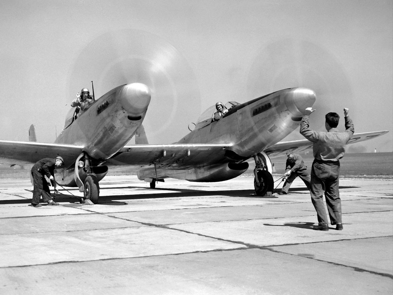
Pilot William Swann, right cockpit, prepares the North American XF-82 Twin Mustang for flight at the National Advisory Committee for Aeronautics (NACA) Lewis Flight Propulsion Laboratory. The aircraft was one of only two prototypes built by North American in October 1945 and powered by Packard Merlin V-1650 piston engines. Over 270 of the F-82 long-distance pursuit fighters were produced during the 1940s. The Mustang’s unique two-pilot configuration allowed one pilot to rest during the long missions and thus be ready for action upon arrival. The NACA took possession of this XF-82 in October 1947. NACA Lewis used the XF-82 as a test bed for ramjet flight tests. Ramjets are continually burning tubes that use the compressed atmospheric air to produce thrust. Ramjets are extremely efficient at high speeds, but rely on some sort of booster to attain that high speed. NACA Lewis undertook an extensive ramjet program in the 1940s that included combustion studies in the Altitude Wind Tunnel, a number of flight tests, and missile drops from aircraft. The 16-inch diameter ramjet missile was fixed to the XF-82 Mustang’s wing and dropped from high altitudes off of Wallops Island. The tests determined the ramjet’s performance and operational characteristics in the transonic range.
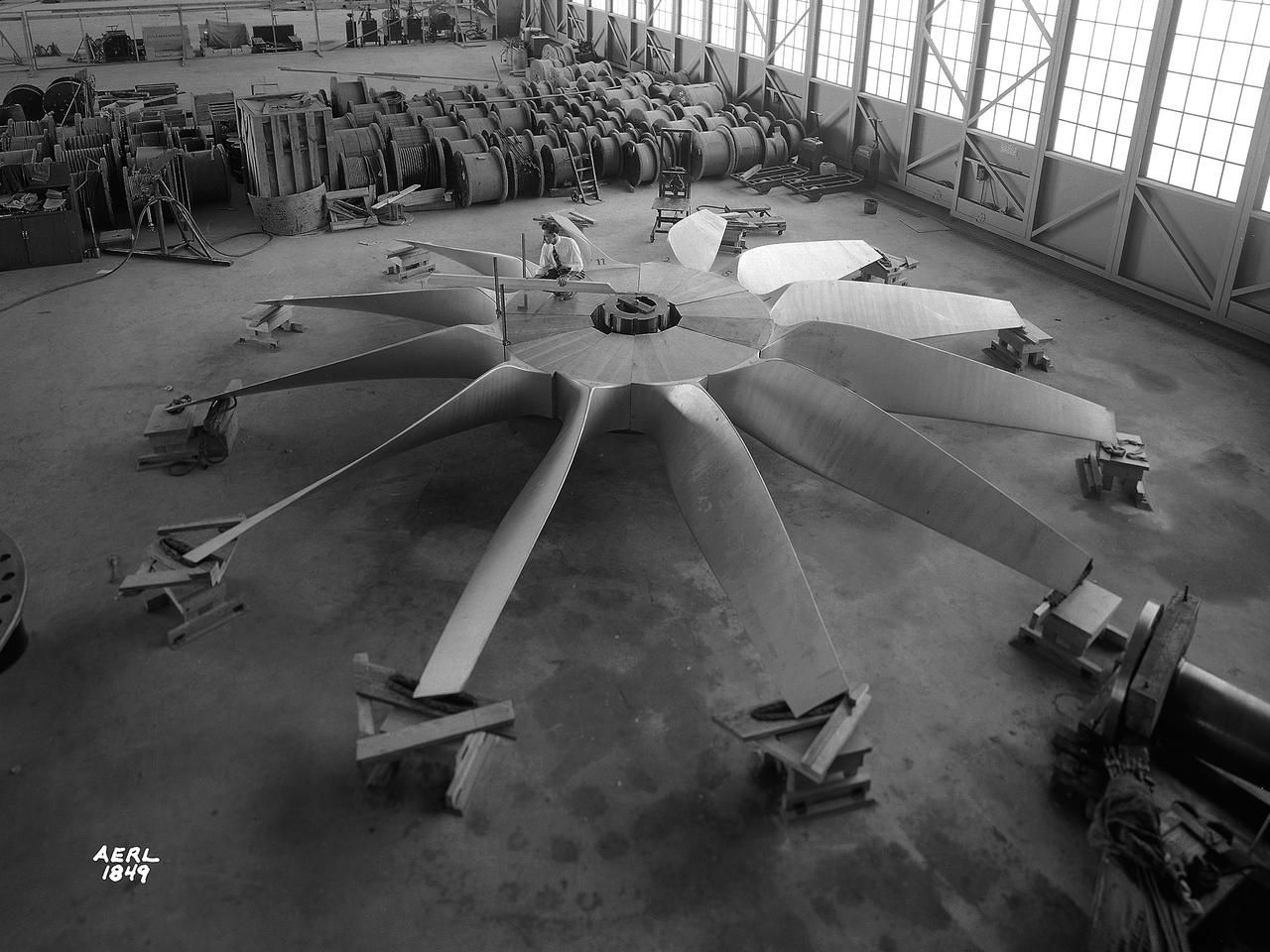
National Advisory Committee for Aeronautics (NACA) engineers assembled the Altitude Wind Tunnel’s (AWT) large wooden drive fan inside the hangar at the Aircraft Engine Research Laboratory. When it was built at the in the early 1940s the AWT was among the most complex test facilities ever designed. It was the first wind tunnel capable of operating full-scale engines under realistic flight conditions. This simulation included the reduction of air temperature, a decrease in air pressure, and the creation of an airstream velocity of up to 500 miles per hour. The AWT was constructed in 1942 and 1943. This photograph shows NACA engineers Lou Hermann and Jack Aust assembling the tunnel’s drive fan inside the hangar. The 12-bladed, 31-foot-diameter spruce wood fan would soon be installed inside the wind tunnel to create the high-speed airflow. This massive propeller was designed and constructed by the engine lab's design team at Langley Field. John Breisch, a Langley technician with several years of wind tunnel installation experience, arrived in Cleveland at the time of this photograph to supervise the fan assembly inside the hangar. He would return several weeks later to oversee the actual installation in the tunnel. The fan was driven at 410 revolutions per minute by an 18,000-horsepower General Electric induction motor that was located in the rear corner of the Exhauster Building. An extension shaft connected the motor to the fan. A bronze screen protected the fan against damage from failed engine parts sailing through the tunnel. Despite this screen the blades did become worn or cracked over time and had to be replaced. An entire new fan was installed in 1951.
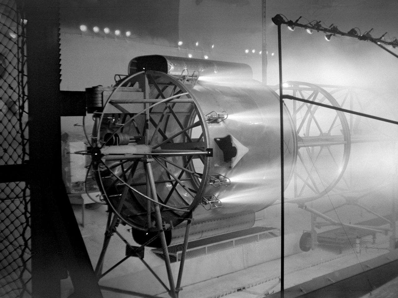
An Atlas/Centaur mass model undergoes a separation test inside the Space Power Chambers at NASA Lewis Research Center. Lewis was in the midst of an extensive effort to prepare the Centaur second-stage rocket for its missions to send the Surveyor spacecraft to the moon as a precursor to the Apollo missions. As part of these preparations, Lewis management decided to convert its Altitude Wind Tunnel into two large test chambers—the Space Power Chambers. The conversion included the removal of the tunnel’s internal components and the insertion of bulkheads to seal off the new chambers within the tunnel. One chamber could simulate conditions found at 100 miles altitude, while this larger chamber simulated the upper atmosphere. In this test series, researchers wanted to verify that the vehicle’s retrorockets would properly separate the Centaur from the Atlas. The model was suspended horizontally on a trolley system inside chamber. A net was hung at one end to catch the jettisoned Atlas model. The chamber atmosphere was reduced to a pressure altitude of 100,000 feet, and high-speed cameras were synchronized to the ignition of the retrorockets. The simulated Centaur is seen here jettisoning from the Atlas out of view to the right. The study resulted in a new jettison method that would significantly reduce the separation time and thus minimize the danger of collision between the two stages during separation.
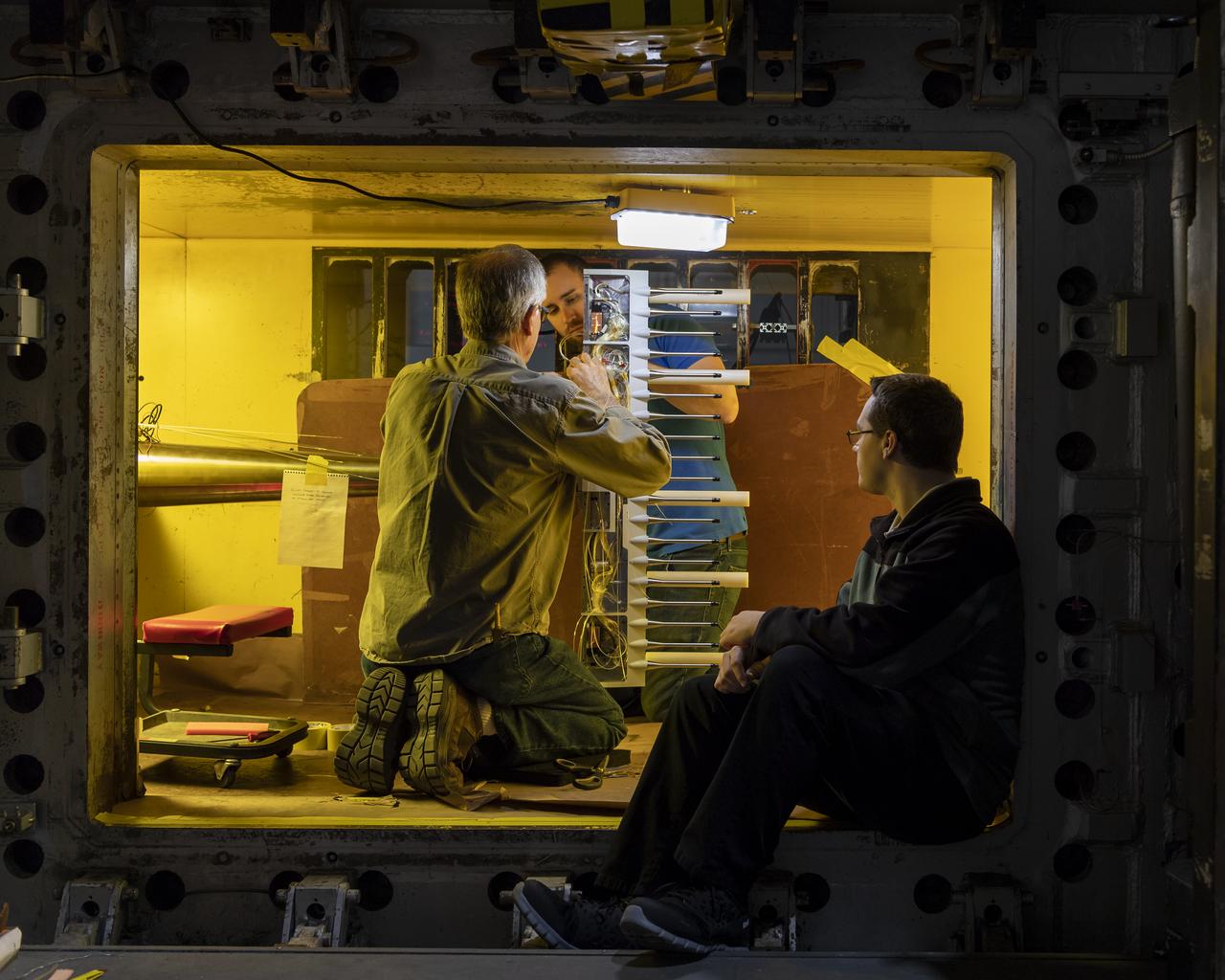
LaRC OCIO's Media Solutions Branch Photographer Harlen Capen photographed the installation of a new flow survey rake for the supersonic Unitary Plan Wind Tunnel (UPWT). The hardware – shown installed in the 4-foot, high-Mach-number Test Section 2 with a coating of Pressure Sensitive Paint – consists of a purpose-built sting, rake body, and two different types of pressure measurement probes. The survey rake will be used to characterize the flow in the test section in support of the "CFD Central Flight Dynamics as a Surrogate for High Speed Supersonic Tests" People in the photo L to R are, Ricky L. Hall, Jacobs Technology, Inc.,Supersonic/Hypersonic Testing Branch - Group A, Alexander (Alex) Moore Jacobs Technology, Inc, Supersonic/Hypersonic Testing Branch and Mathew A. (Alec) Reed, Jacobs Technology, In. NASA photographer Harlen Capen won First Place in the NASA's 2019 Still Photographer of the Year competition in the "People" category with this image.
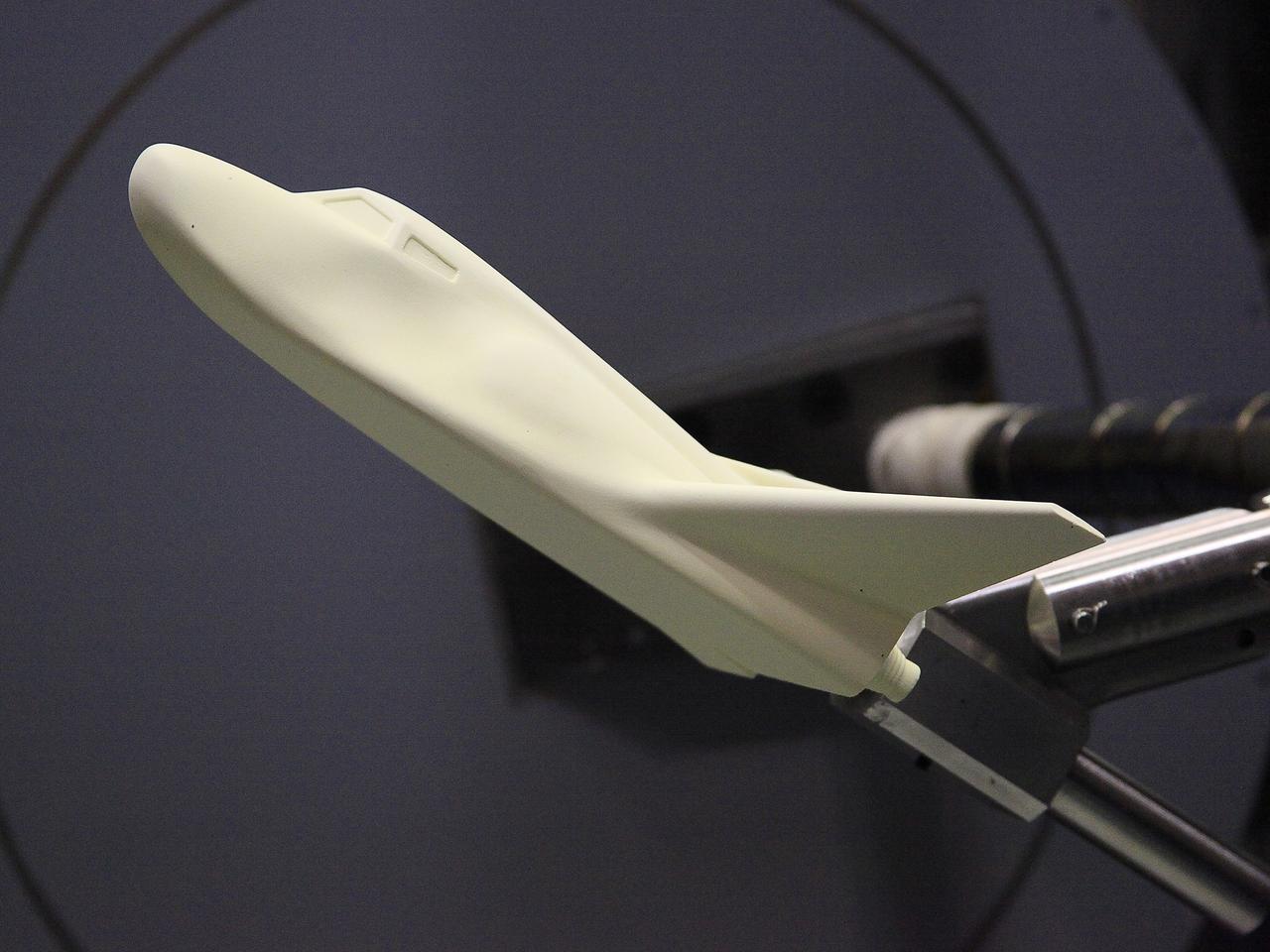
HAMPTON, Va. –A 10-inch long ceramic model of the Sierra Nevada Corporation, or SNC, Dream Chaser spacecraft is prepared for high-speed wind tunnel tests at NASA's Langley Research Center in Hampton, Va. The tests measure how much heat the winged vehicle would experience during ascent and re-entry through the atmosphere, including the spacecraft's lower- and upper-body flaps, elevons and a rudder. They're also helping the company obtain necessary data for the material selection and design of the spacecraft's thermal protection system. SNC is continuing the development of its Dream Chaser spacecraft under the agency's Commercial Crew Integrated Capability, or CCiCap, initiative, which is intended to lead to the availability of commercial human spaceflight services for government and commercial customers. To learn more about CCP and its industry partners, visit www.nasa.gov/commercialcrew. Image credit: NASA/David Bowman
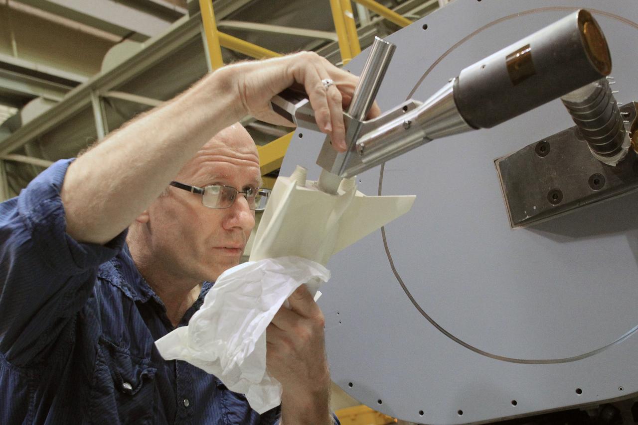
HAMPTON, Va. –A 10-inch long ceramic model of the Sierra Nevada Corporation, or SNC, Dream Chaser spacecraft is prepared for high-speed wind tunnel tests at NASA's Langley Research Center in Hampton, Va. The tests measure how much heat the winged vehicle would experience during ascent and re-entry through the atmosphere, including the spacecraft's lower- and upper-body flaps, elevons and a rudder. They're also helping the company obtain necessary data for the material selection and design of the spacecraft's thermal protection system. SNC is continuing the development of its Dream Chaser spacecraft under the agency's Commercial Crew Integrated Capability, or CCiCap, initiative, which is intended to lead to the availability of commercial human spaceflight services for government and commercial customers. To learn more about CCP and its industry partners, visit www.nasa.gov/commercialcrew. Image credit: NASA/David Bowman
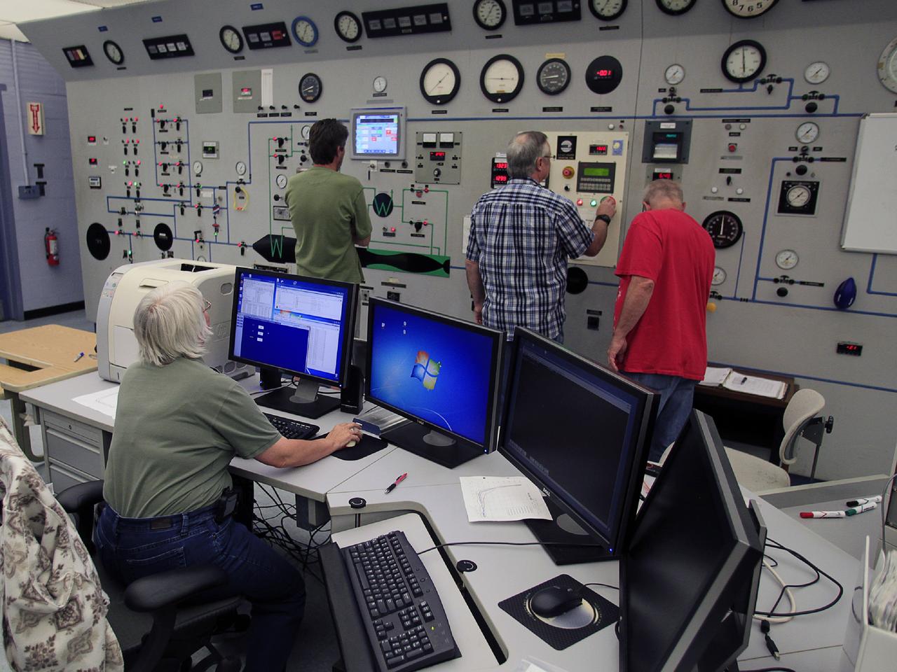
HAMPTON, Va. –Engineers monitor high-speed wind tunnel testing of a 10-inch long ceramic model of the Sierra Nevada Corporation, or SNC, Dream Chaser spacecraft at NASA's Langley Research Center in Hampton, Va. The tests measure how much heat the winged vehicle would experience during ascent and re-entry through the atmosphere, including the spacecraft's lower- and upper-body flaps, elevons and a rudder. They're also helping the company obtain necessary data for the material selection and design of the spacecraft's thermal protection system. SNC is continuing the development of its Dream Chaser spacecraft under the agency's Commercial Crew Integrated Capability, or CCiCap, initiative, which is intended to lead to the availability of commercial human spaceflight services for government and commercial customers. To learn more about CCP and its industry partners, visit www.nasa.gov/commercialcrew. Image credit: NASA/David Bowman
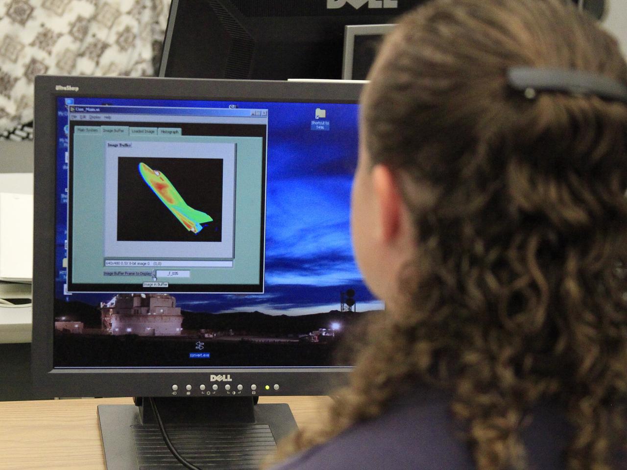
HAMPTON, Va. –An engineer monitors high-speed wind tunnel testing of a 10-inch long ceramic model of the Sierra Nevada Corporation, or SNC, Dream Chaser spacecraft at NASA's Langley Research Center in Hampton, Va. The tests measure how much heat the winged vehicle would experience during ascent and re-entry through the atmosphere, including the spacecraft's lower- and upper-body flaps, elevons and a rudder. They're also helping the company obtain necessary data for the material selection and design of the spacecraft's thermal protection system. SNC is continuing the development of its Dream Chaser spacecraft under the agency's Commercial Crew Integrated Capability, or CCiCap, initiative, which is intended to lead to the availability of commercial human spaceflight services for government and commercial customers. To learn more about CCP and its industry partners, visit www.nasa.gov/commercialcrew. Image credit: NASA/David Bowman
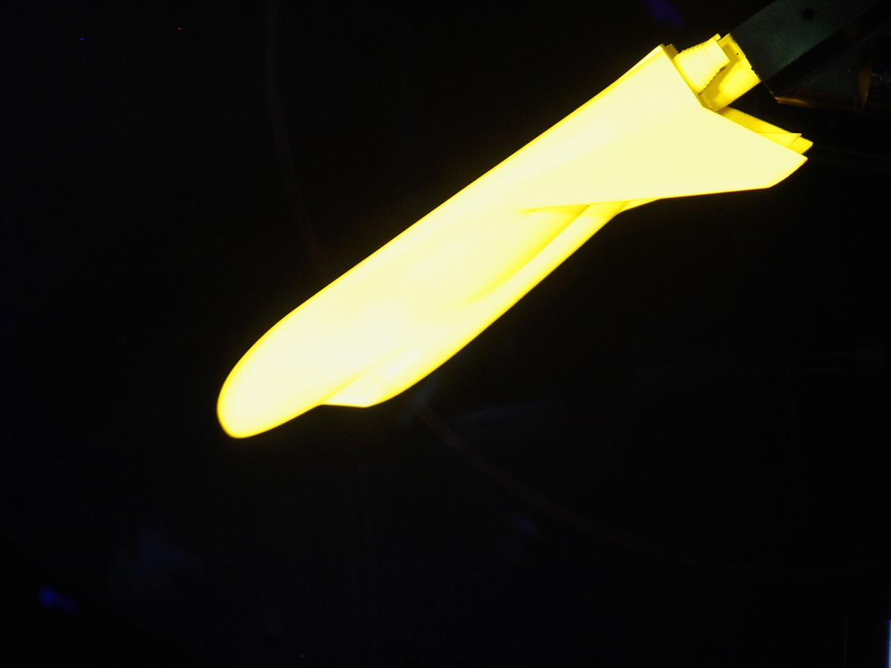
HAMPTON, Va. –A 10-inch long ceramic model of the Sierra Nevada Corporation, or SNC, Dream Chaser spacecraft undergoes high-speed wind tunnel tests at NASA's Langley Research Center in Hampton, Va. The tests measure how much heat the winged vehicle would experience during ascent and re-entry through the atmosphere, including the spacecraft's lower- and upper-body flaps, elevons and a rudder. They're also helping the company obtain necessary data for the material selection and design of the spacecraft's thermal protection system. SNC is continuing the development of its Dream Chaser spacecraft under the agency's Commercial Crew Integrated Capability, or CCiCap, initiative, which is intended to lead to the availability of commercial human spaceflight services for government and commercial customers. To learn more about CCP and its industry partners, visit www.nasa.gov/commercialcrew. Image credit: NASA/David Bowman
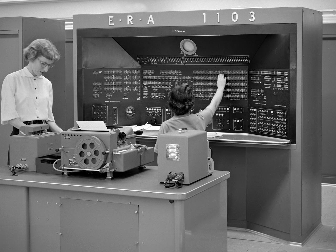
The new 10-by 10-Foot Supersonic Wind Tunnel at the Lewis Flight Propulsion Laboratory included high tech data acquisition and analysis systems. The reliable gathering of pressure, speed, temperature, and other data from test runs in the facilities was critical to the research process. Throughout the 1940s and early 1950s female employees, known as computers, recorded all test data and performed initial calculations by hand. The introduction of punch card computers in the late 1940s gradually reduced the number of hands-on calculations. In the mid-1950s new computational machines were installed in the office building of the 10-by 10-Foot tunnel. The new systems included this UNIVAC 1103 vacuum tube computer—the lab’s first centralized computer system. The programming was done on paper tape and fed into the machine. The 10-by 10 computer center also included the Lewis-designed Computer Automated Digital Encoder (CADDE) and Digital Automated Multiple Pressure Recorder (DAMPR) systems which converted test data to binary-coded decimal numbers and recorded test pressures automatically, respectively. The systems primarily served the 10-by 10, but were also applied to the other large facilities. Engineering Research Associates (ERA) developed the initial UNIVAC computer for the Navy in the late 1940s. In 1952 the company designed a commercial version, the UNIVAC 1103. The 1103 was the first computer designed by Seymour Cray and the first commercially successful computer.
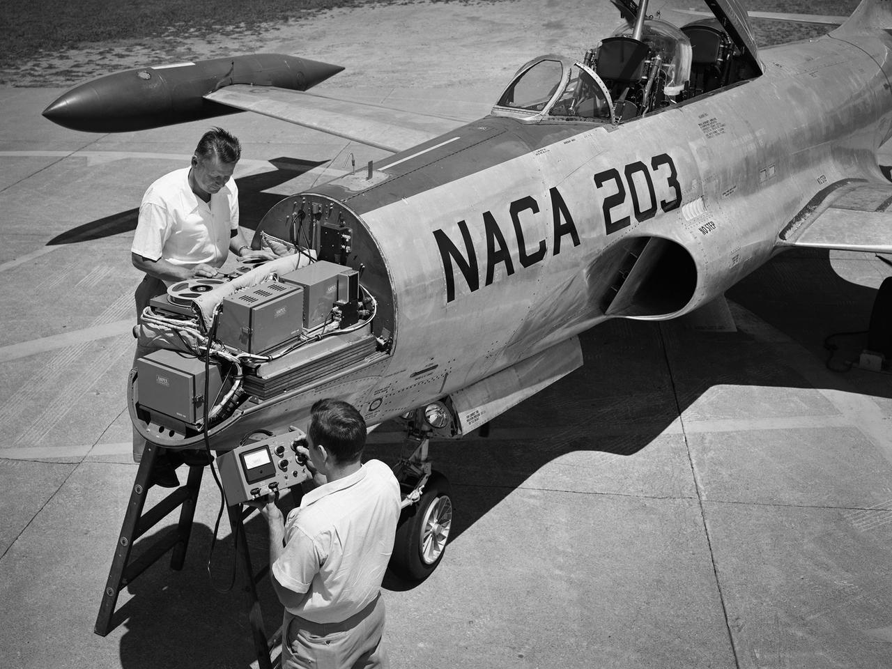
A Lockheed F-94B Starfire being equipped with an audio recording machine and sensors at the National Advisory Committee for Aeronautics (NACA) Lewis Flight Propulsion Laboratory. The NACA was investigating the acoustic effects caused by the engine’s nozzle and the air flowing along the fuselage. Airline manufacturers would soon be introducing jet engines on their passenger aircraft, and there was concern regarding the noise levels for both the passengers and public on the ground. NACA Lewis conducted a variety of noise reduction studies in its wind tunnels, laboratories, and on a F2H-2B Banshee aircraft. The F2H-2B Banshee’s initial test flights in 1955 and 1956 measured the noise emanating directly from airflow over the aircraft’s surfaces, particularly the wings. This problem was particularly pronounced at high subsonic speeds. The researchers found the majority of the noise occurred in the low and middle octaves. These investigations were enhanced with a series of flights using the F-94B Starfire. The missions measured wall-pressure, turbulence fluctuations, and mean velocity profiles. Mach 0.3 to 0.8 flights were flown at altitudes of 10,000, 20,000, and 30,000 feet with microphones mounted near the forward fuselage and on a wing. The results substantiated the wind tunnel findings. This photograph shows the tape recorder being installed in the F-94B’s nose.
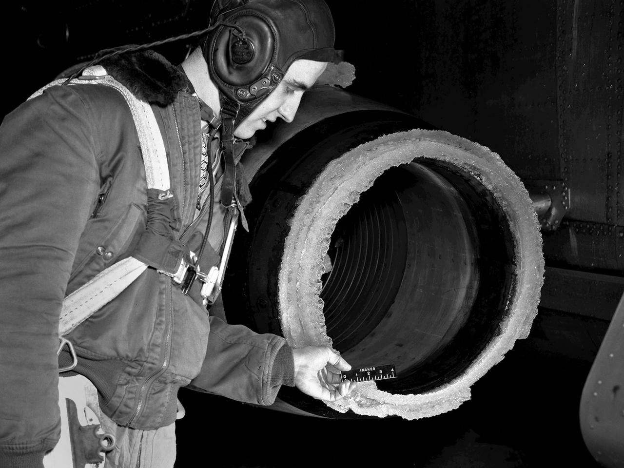
The National Advisory Committee for Aeronautics (NACA) Lewis Flight Propulsion Laboratory conducted an extensive icing research program in the late 1940s that included studies in the Icing Research Tunnel and using specially modified aircraft. One facet of this program was the investigation of the effects of icing on turbojets. Although jet engines allowed aircraft to pass through inclement weather at high rates of speed, ice accumulation was still a concern. The NACA’s B-24M Liberator was initially reconfigured with a General Electric I-16 engine installed in the aircraft’s waist compartment with an air scoop and spray nozzles to produce the artificial icing conditions. The centrifugal engine appeared nearly impervious to the effects of icing. Axial-flow jet engines, however, were much more susceptible to icing damage. The inlet guide vanes were particularly vulnerable, but the cowling’s leading edge, the main bearing supports, and accessory housing could also ice up. If pieces of ice reached the engine’s internal components, the compressor blades could be damaged. To study this phenomenon, a Westinghouse 24C turbojet, seen in this photograph, was installed under the B-24M’s right wing. In January 1948 flight tests of the 24C in icing conditions began. Despite ice buildup into the second stage of the compressor, the engine was able to operate at takeoff speeds. Researchers found the ice on the inlet vanes resulted in half of the engine’s decreased performance.
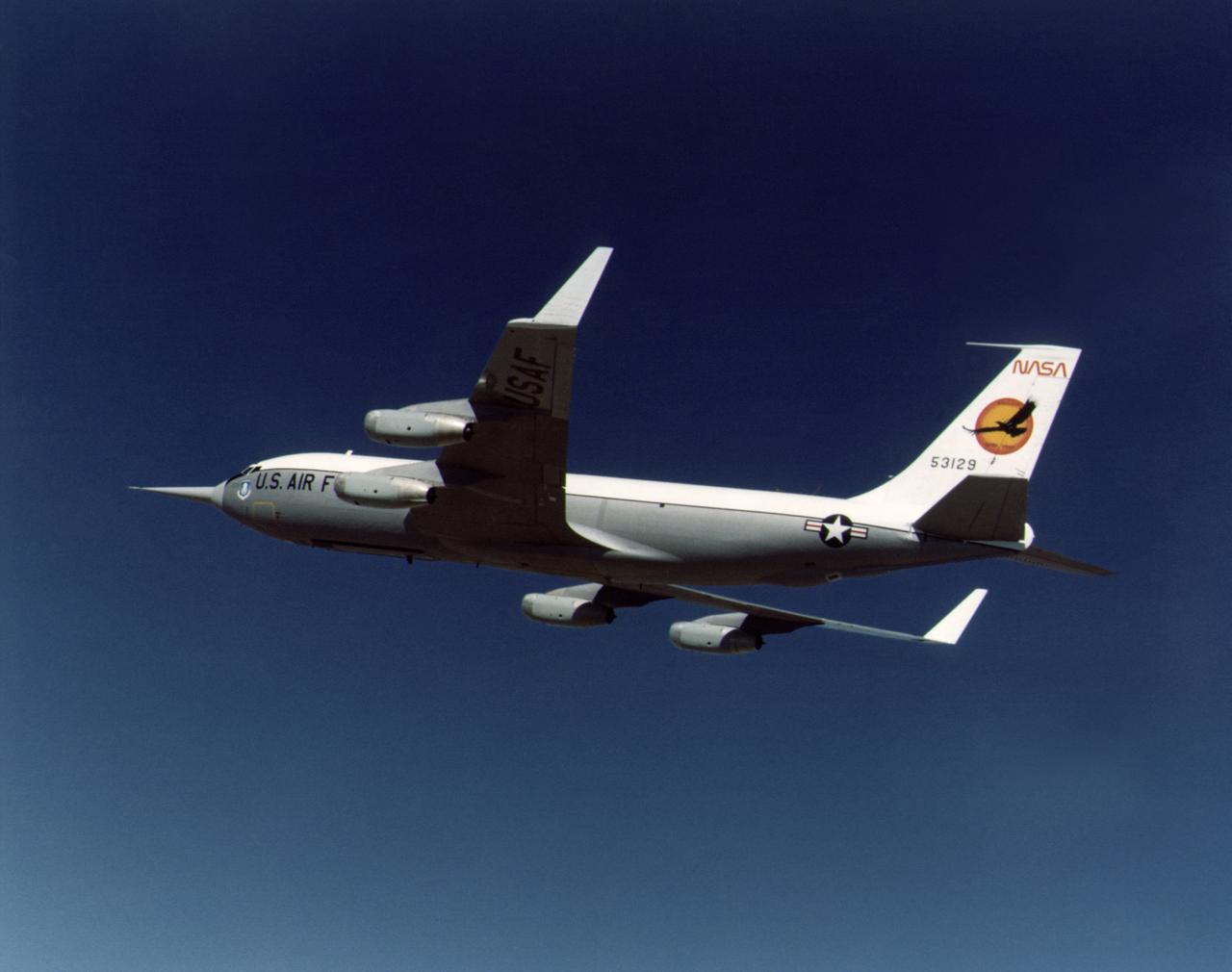
During the 1970s, the focus at Dryden shifted from high-speed and high-altitude flight to incremental improvements in technology and aircraft efficiency. One manifestation of this trend occurred in the winglet flight research carried out on a KC-135 during 1979 and 1980. Richard Whitcomb at the Langley Research Center had originated the idea of adding small vertical fins to an aircraft's wing tips. His wind tunnel tests indicated that winglets produced a forward thrust, which reduced the strength of the vortices generated by an aircraft's wing tips and resulted in a reduction of drag and an increase in aircraft range. Whitcomb, who had previously developed the area rule concept and the supercritical wing, selected the best winglet shape for flight tests on a KC-135 tanker. When the tests were completed, the data showed that the winglets provided a 7 percent improvement in range over the standard KC-135. The obvious economic advantage at a time of high fuel costs caused winglets to be adopted on business jets, airliners, and heavy military transports.
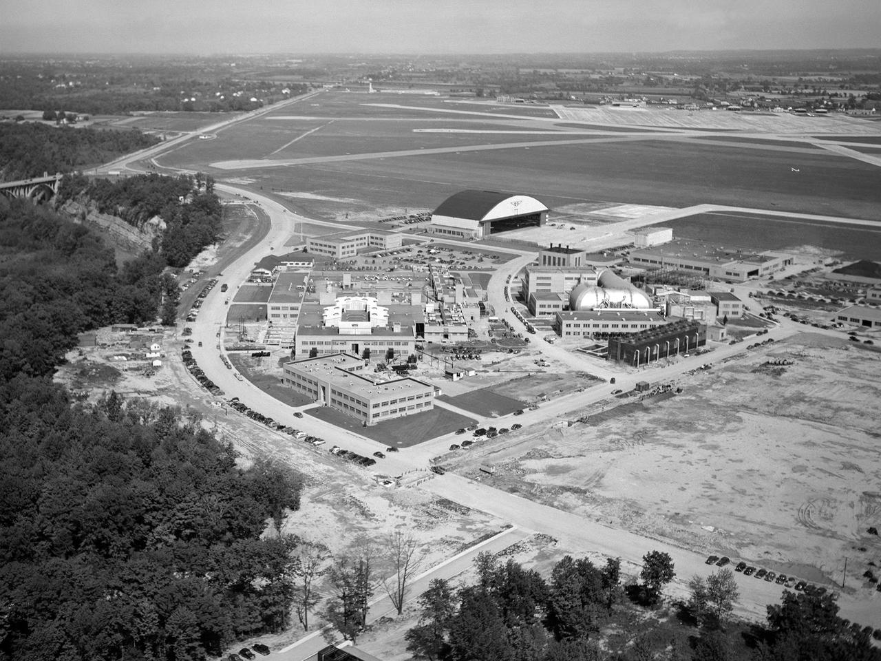
The National Advisory Committee for Aeronautics (NACA) Lewis Flight Propulsion Laboratory in Cleveland, Ohio as seen from the west in May 1946. The Cleveland Municipal Airport is located directly behind. The laboratory was built in the early 1940s to resolve problems associated with aircraft engines. The initial campus contained seven principal buildings: the Engine Research Building, hangar, Fuels and Lubricants Building, Administration Building, Engine Propeller Research Building, Altitude Wind Tunnel, and Icing Research Tunnel. These facilities and their associated support structures were located within an area occupying approximately one-third of the NACA’s property. After World War II ended, the NACA began adding new facilities to address different problems associated with the newer, more powerful engines and high speed flight. Between 1946 and 1955, four new world-class test facilities were built: the 8- by 6-Foot Supersonic Wind Tunnel, the Propulsion Systems Laboratory, the Rocket Engine Test Facility, and the 10- by 10-Foot Supersonic Wind Tunnel. These large facilities occupied the remainder of the NACA’s semicircular property. The Lewis laboratory expanded again in the late 1950s and early 1960s as the space program commenced. Lewis purchased additional land in areas adjacent to the original laboratory and acquired a large 9000-acre site located 60 miles to the west in Sandusky, Ohio. The new site became known as Plum Brook Station.

One of the two primary coolers at the Propulsion Systems Laboratory at the National Advisory Committee for Aeronautics (NACA) Lewis Flight Propulsion Laboratory. Engines could be run in simulated altitude conditions inside the facility’s two 14-foot-diameter and 24-foot-long test chambers. The Propulsion Systems Laboratory was the nation’s only facility that could run large full-size engine systems in controlled altitude conditions. At the time of this photograph, construction of the facility had recently been completed. Although not a wind tunnel, the Propulsion Systems Laboratory generated high-speed airflow through the interior of the engine. The air flow was pushed through the system by large compressors, adjusted by heating or refrigerating equipment, and de-moisturized by air dryers. The exhaust system served two roles: reducing the density of the air in the test chambers to simulate high altitudes and removing hot gases exhausted by the engines being tested. It was necessary to reduce the temperature of the extremely hot engine exhaust before the air reached the exhauster equipment. As the air flow exited through exhaust section of the test chamber, it entered into the giant primary cooler seen in this photograph. Narrow fins or vanes inside the cooler were filled with water. As the air flow passed between the vanes, its heat was transferred to the cooling water. The cooling water was cycled out of the system, carrying with it much of the exhaust heat.
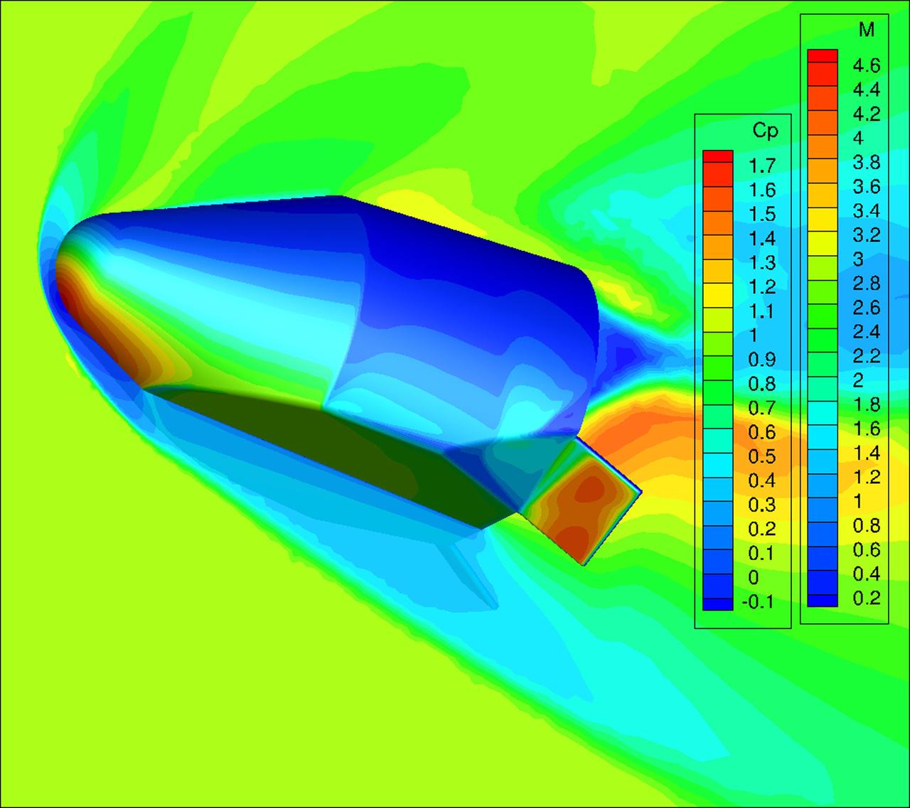
DALLAS – This computational fluid dynamics CFD image was taken during a series of wind tunnel tests for Blue Origin's next-generation Space Vehicle at Lockheed Martin's High Speed Wind Tunnel Facility in Dallas. The Space Vehicle's innovative biconic shape is designed to provide more cross-range and interior volume than a traditional capsule and weigh less than a winged vehicle. More than 180 wind tunnel tests validated the company's analysis of the Space Vehicle's aerodynamics during descent through the atmosphere and the ability to change its flight path, which could increase the number of available landing opportunities and enhance the vehicle's emergency return capability. In 2011, NASA selected Blue Origin during Commercial Crew Development Round 2 CCDev2) activities for NASA’s Commercial Crew Program to mature the design and development of a crew transportation system with the overall goal of accelerating a United States-led capability to the International Space Station. The goal of CCP is to drive down the cost of space travel as well as open up space to more people than ever before by balancing industry’s own innovative capabilities with NASA's 50 years of human spaceflight experience. Six other aerospace companies also are maturing launch vehicle and spacecraft designs under CCDev2, including Alliant Techsystems Inc. ATK, The Boeing Co., Excalibur Almaz Inc., Sierra Nevada Corp., Space Exploration Technologies SpaceX, and United Launch Alliance ULA. For more information, visit www.nasa.gov/commercialcrew. Image credit: Blue Origin
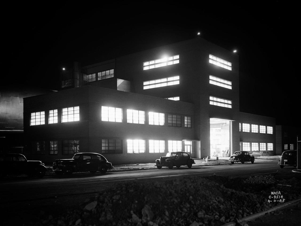
The Altitude Wind Tunnel (AWT) during one of its overnight runs at the National Advisory Committee for Aeronautics (NACA) Aircraft Engine Research Laboratory in Cleveland, Ohio. The AWT was run during night hours so that its massive power loads were handled when regional electric demands were lowest. At the time the AWT was among the most complex wind tunnels ever designed. In order to simulate conditions at high altitudes, NACA engineers designed innovative new systems that required tremendous amounts of electricity. The NACA had an agreement with the local electric company that it would run its larger facilities overnight when local demand was at its lowest. In return the utility discounted its rates for the NACA during those hours. The AWT could produce wind speeds up to 500 miles per hour through its 20-foot-diameter test section at the standard operating altitude of 30,000 feet. The airflow was created by a large fan that was driven by an 18,000-horsepower General Electric induction motor. The altitude simulation was accomplished by large exhauster and refrigeration systems. The cold temperatures were created by 14 Carrier compressors and the thin atmosphere by four 1750-horsepower exhausters. The first and second shifts usually set up and broke down the test articles, while the third shift ran the actual tests. Engineers would often have to work all day, then operate the tunnel overnight, and analyze the data the next day. The night crew usually briefed the dayshift on the tests during morning staff meetings.
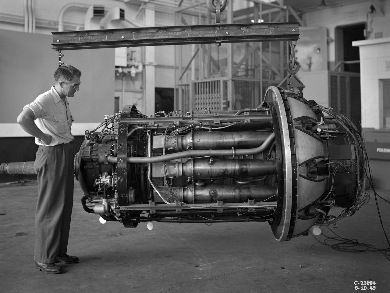
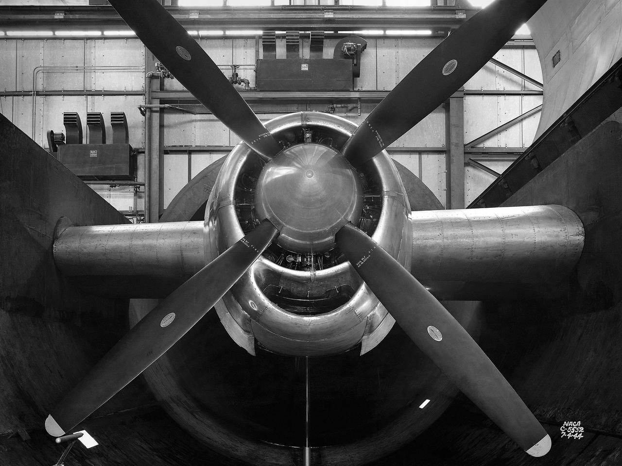
A 3670-horsepower Armstrong-Siddeley Python turboprop being prepared for tests in the Altitude Wind Tunnel at the National Advisory Committee for Aeronautics (NACA) Lewis Flight Propulsion Laboratory. In 1947 Lewis researcher Walter Olsen led a group of representatives from the military, industry, and the NACA on a fact finding mission to investigate the technological progress of British turbojet manufacturers. Afterwards several British engines, including the Python, were brought to Cleveland for testing in Lewis’s altitude facilities. The Python was a 14-stage axial-flow compressor turboprop with a fixed-area nozzle and contra-rotating propellers. Early turboprops combined the turbojet and piston engine technologies. They could move large quantities of air so required less engine speed and thus less fuel. This was very appealing to the military for some applications. The military asked the NACA to compare the Python’s performance at sea to that at high altitudes. The NACA researchers studied the Python in the Altitude Wind Tunnel from July 1949 through January 1950. It was the first time the tunnel was used to study an engine with the sole purpose of learning about, not improving it. They analyzed the engine’s dynamic response using a frequency response method at altitudes between 10,000 to 30,000 feet. Lewis researchers found that they could predict the dynamic response characteristics at any altitude from the data obtained from any other specific altitude. This portion of the testing was completed during a single test run.
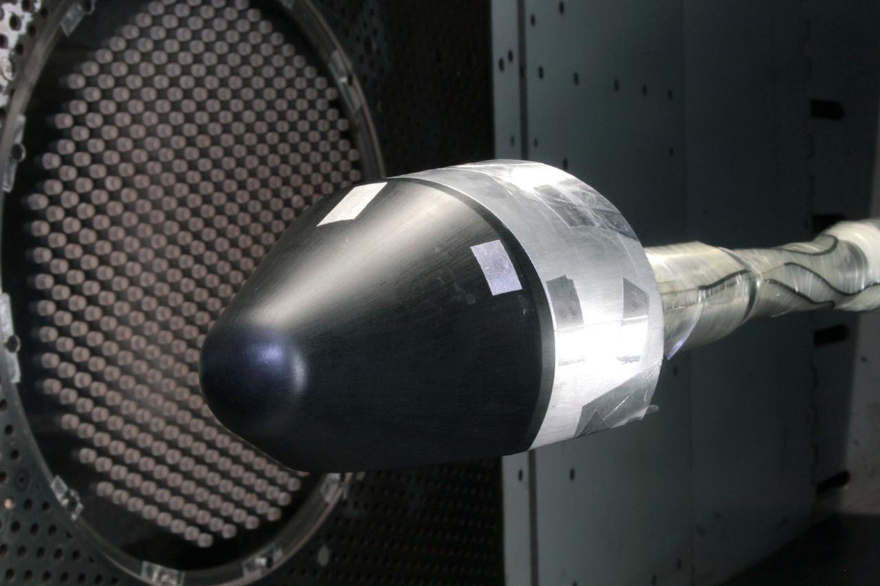
DALLAS – This image was taken during a series of wind tunnel tests for Blue Origin's Space Vehicle at Lockheed Martin's High Speed Wind Tunnel Facility in Dallas. The Space Vehicle's innovative biconic shape is designed to provide more cross-range and interior volume than a traditional capsule and weigh less than a winged vehicle. More than 180 wind tunnel tests validated the company's analysis of the Space Vehicle's aerodynamics during descent through the atmosphere and the ability to change its flight path, which could increase the number of available landing opportunities and enhance the vehicle's emergency return capability. In 2011, NASA selected Blue Origin during Commercial Crew Development Round 2 CCDev2) activities for NASA’s Commercial Crew Program to mature the design and development of a crew transportation system with the overall goal of accelerating a United States-led capability to the International Space Station. The goal of CCP is to drive down the cost of space travel as well as open up space to more people than ever before by balancing industry’s own innovative capabilities with NASA's 50 years of human spaceflight experience. Six other aerospace companies also are maturing launch vehicle and spacecraft designs under CCDev2, including Alliant Techsystems Inc. ATK, The Boeing Co., Excalibur Almaz Inc., Sierra Nevada Corp., Space Exploration Technologies SpaceX, and United Launch Alliance ULA. For more information, visit www.nasa.gov/commercialcrew. Image credit: Blue Origin

A mechanic and apprentice work on a wooden impeller in the Fabrication Shop at the NACA Lewis Flight Propulsion Laboratory. The 260-person Fabrication Division created almost all of the equipment and models used at the laboratory. The Technical Services Building, referred to as the “Fab Shop”, contained a number of specialized shops in the 1940s and 1950s. These included a Machine Shop, Sheet Metal Shop, Wood and Pattern Shop, Instrument Shop, Thermocouple Shop, Heat Treating Shop, Metallurgical Laboratory, and Fabrication Office. The Machine Shop fabricated research equipment not commercially available. During World War II these technicians produced high-speed cameras for combustion research, impellers and other supercharger components, and key equipment for the lab’s first supersonic wind tunnel. The Wood and Pattern Shop created everything from control panels and cabinets to aircraft model molds for sheet metal work. The Sheet Metal Shop had the ability to work with 0.01 to 4-inches thick steel plates. The Instrument Shop specialized in miniature parts and instrumentation, while the Thermocouple Shop standardized the installation of pitot tubes and thermocouples. The Metallurgical Laboratory contained a control lab for the Heat Treating Shop and a service lab for the NACA Lewis research divisions. The Heat Treating Shop heated metal parts to optimize their physical properties and contained a Precision Castings Foundry to manufacture equipment made of heat resisting alloys.
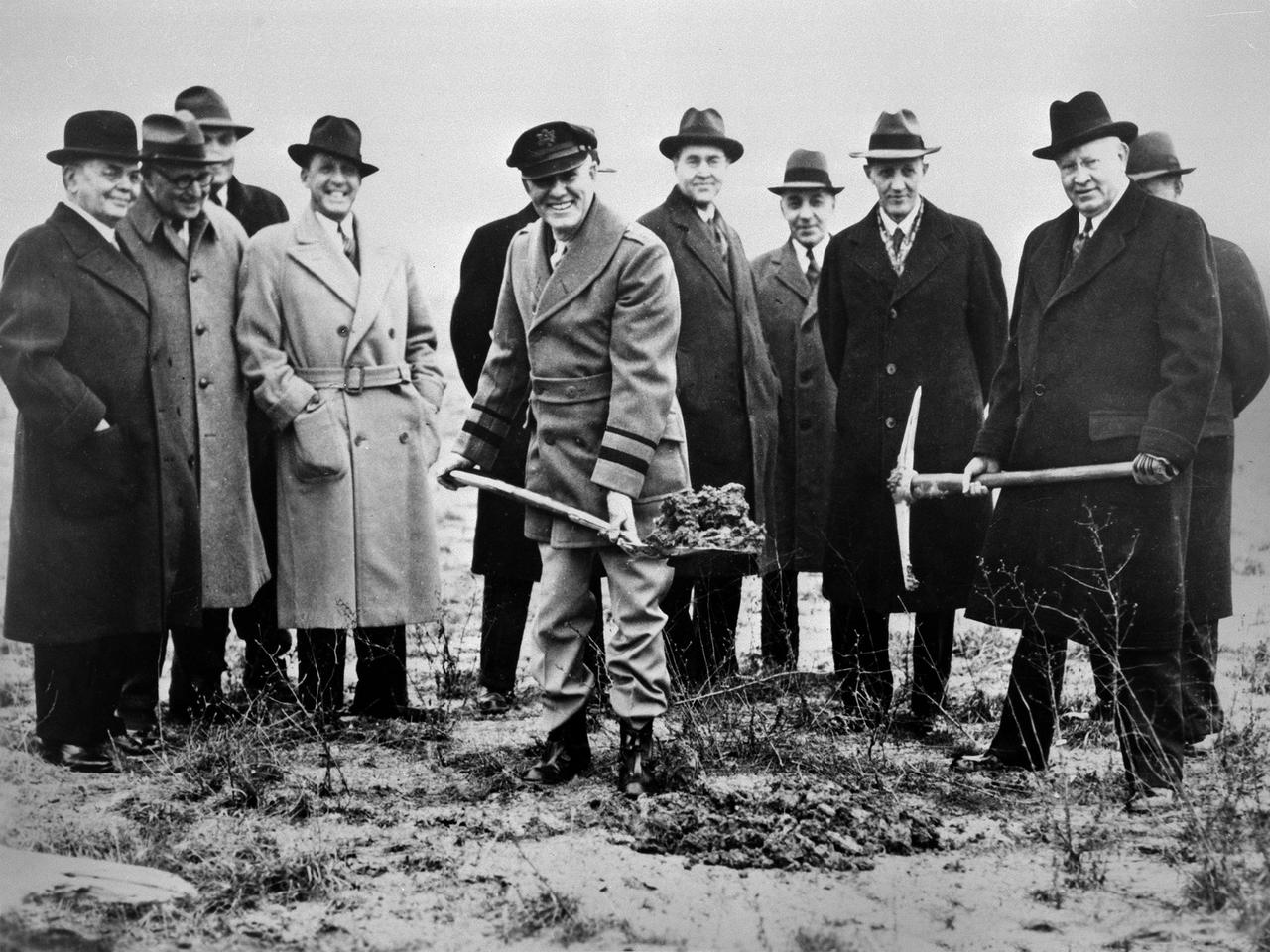
Local politicians and National Advisory Committee for Aeronautics (NACA) officials were on hand for the January 23, 1941 groundbreaking for the NACA’s Aircraft Engine Research Laboratory (AERL). The NACA was established in 1915 to coordinate the nation’s aeronautical research. The committee opened a research laboratory at Langley Field in 1920. By the late 1930s, however, European nations, Germany in particular, were building faster and higher flying aircraft. The NACA decided to expand with a new Ames Aeronautical Laboratory dedicated to high-speed flight and the AERL to handle engine-related research. The NACA examined a number of Midwest locations for its new engine lab before deciding on Cleveland. At the time, Cleveland possessed the nation’s most advanced airport, several key aircraft manufacturing companies, and was home to the National Air Races. Local officials were also able to broker a deal with the power company to discount its electricity rates if the large wind tunnels were operated overnight. The decision was made in October 1940, and the groundbreaking alongside the airport took place on January 23, 1941. From left to right: William Hopkins, John Berry, Ray Sharp, Frederick Crawford, George Brett, Edward Warner, Sydney Kraus, Edward Blythin, and George Lewis
The resolution of the Boeing B-29 Superfortress’ engine cooling problems was one of the Aircraft Engine Research Laboratory’s (AERL) key contributions to the World War II effort. The B-29 leapfrogged previous bombers in size, speed, and altitude capabilities. The B–29 was intended to soar above anti-aircraft fire and make pinpoint bomb drops onto strategic targets. Four Wright Aeronautical R-3350 engines powered the massive aircraft. The engines, however, frequently strained and overheated due to payload overloading. This resulted in a growing number of engine fires that often resulted in crashes. The military asked the NACA to tackle the overheating issue. Full-scale engine tests on a R–3350 engine in the Prop House demonstrated that a NACA-designed impeller increased the fuel injection system’s flow rate. Single-cylinder studies resolved a valve failure problem by a slight extension of the cylinder head, and researchers in the Engine Research Building combated uneven heating with a new fuel injection system. Investigations during the summer of 1944 in the Altitude Wind Tunnel, which could simulate flight conditions at high altitudes, led to reduction of drag and improved air flow by reshaping the cowling inlet and outlet. The NACA modifications were then flight tested on a B-29 bomber that was brought to the AERL.
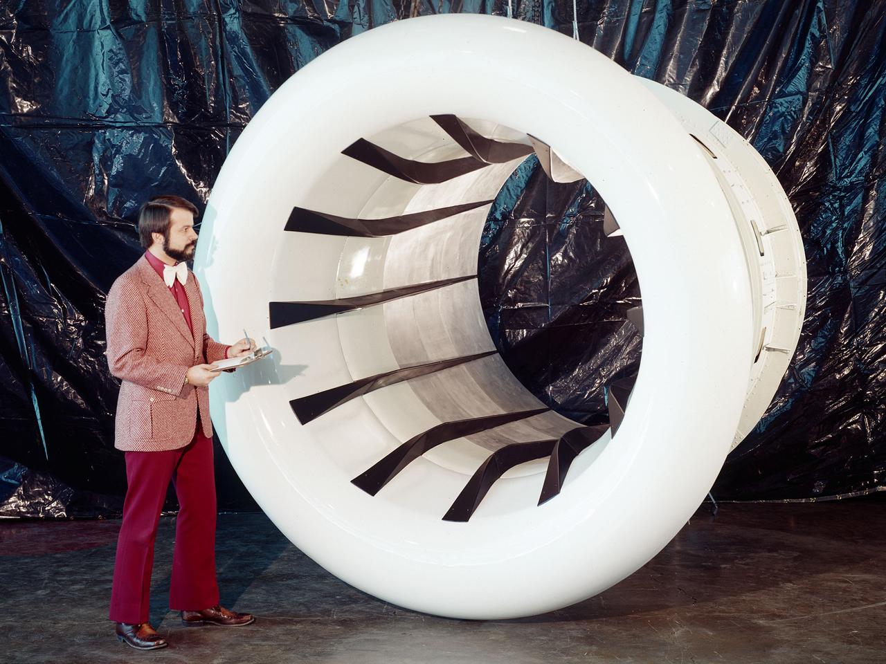
Brent Miller, of the V/STOL and Noise Division at the National Aeronautics and Space Administration (NASA) Lewis Research Center, poses with a sonic inlet for the NASA Quiet Engine Program. NASA Lewis had first investigated methods for reducing aircraft engine noise in the mid-1950s. Those efforts were resurrected and expanded in the late 1960s. The researchers found that the use of a sonic, or high-throat-Mach-number, inlet was effective at reducing the noise from the engine inlet. The device accelerated the inlet air to near-sonic speeds which kept the forward moving sound waves away from the inlet. The device also deflected the sound waves into the wall to further reduce the noise. NASA Lewis researchers tested models of the sonic inlet in their 9- by 15-Foot Low Speed Wind Tunnel. They found that the general level of aerodynamic performance was good. The tests during simulated takeoff and landing conditions demonstrated the sonic inlet’s ability to provide good aerodynamic and acoustic performance The researchers then successfully tested two full-scale sonic inlet designs, one from Pratt and Whitney and one from General Electric, with fans. A full-scale engine was installed on a thrust stand to determine the sonic inlet’s effect on the engine’s performance. The amount of noise reduction increased as the inlet flow velocity increased, but the full-scale tests did not produce as great a decrease in noise as the earlier small-scale tests.
![Astronaut Neil Armstrong examines a Vertical and Short Takeoff and Landing test setup in the 9- by 15-Foot Low Speed Wind Tunnel at the National Aeronautics and Space Administration (NASA) Lewis Research Center. Armstrong spent February 6, 1970 at Lewis attending technical meetings and touring some facilities. Just six months after Armstrong had returned from the moon looming agency budget cuts were already a concern in his comments. He noted that NASA had to “find a balanced approach…and [make] aggressive use of available facilities.” Armstrong spent four months at the center as a research pilot in 1955. Armstrong had served as a Navy pilot during the Korean War then earned a degree in aeronautical engineering at Purdue University. He was recruited by Lewis while at Purdue and began at the center shortly after graduation. During his brief tenure in Cleveland Armstrong served as both a test pilot and research engineer, primarily involved with icing research. In his role as research pilot Armstrong also flew a North American F-82 Twin Mustang over the ocean near Wallops Island to launch small instrumented rockets from high altitudes down into the atmosphere to obtain high Mach numbers. After four months in Cleveland a position opened up at what is today the Dryden Flight Research Center. Armstrong’s career in Cleveland officially ended on June 30, 1955.](https://images-assets.nasa.gov/image/GRC-1970-C-00473/GRC-1970-C-00473~medium.jpg)
Astronaut Neil Armstrong examines a Vertical and Short Takeoff and Landing test setup in the 9- by 15-Foot Low Speed Wind Tunnel at the National Aeronautics and Space Administration (NASA) Lewis Research Center. Armstrong spent February 6, 1970 at Lewis attending technical meetings and touring some facilities. Just six months after Armstrong had returned from the moon looming agency budget cuts were already a concern in his comments. He noted that NASA had to “find a balanced approach…and [make] aggressive use of available facilities.” Armstrong spent four months at the center as a research pilot in 1955. Armstrong had served as a Navy pilot during the Korean War then earned a degree in aeronautical engineering at Purdue University. He was recruited by Lewis while at Purdue and began at the center shortly after graduation. During his brief tenure in Cleveland Armstrong served as both a test pilot and research engineer, primarily involved with icing research. In his role as research pilot Armstrong also flew a North American F-82 Twin Mustang over the ocean near Wallops Island to launch small instrumented rockets from high altitudes down into the atmosphere to obtain high Mach numbers. After four months in Cleveland a position opened up at what is today the Dryden Flight Research Center. Armstrong’s career in Cleveland officially ended on June 30, 1955.