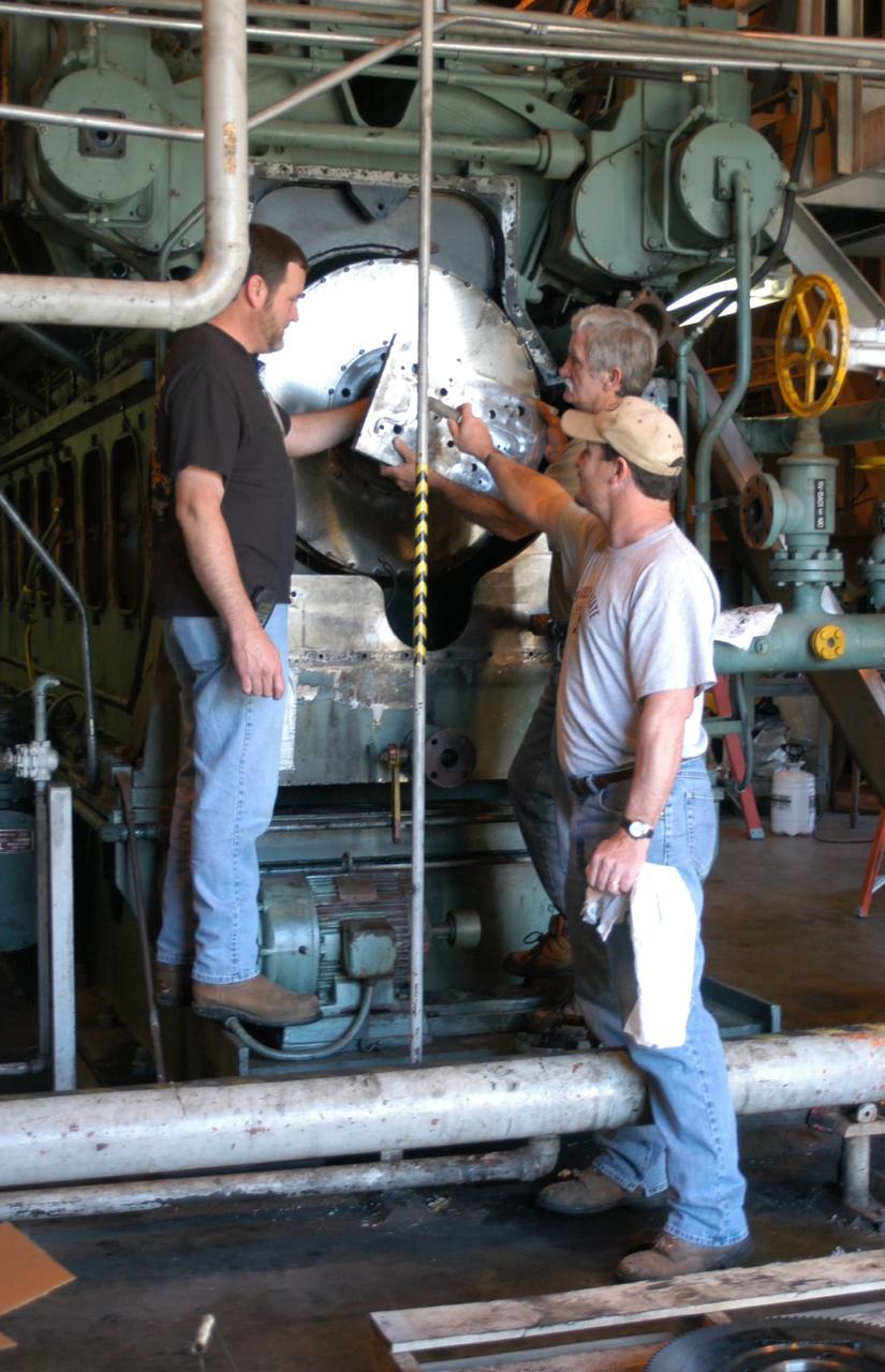
NASA Test Operations Group employees, from left, Todd Pearson, Tim Delcuze and Rodney Wilkinson maintain a water pump in Stennis Space Center's high-pressure water facility. The three were part of a group of employees who rode out Hurricane Katrina at the facility and helped protect NASA's rocket engine test complex.
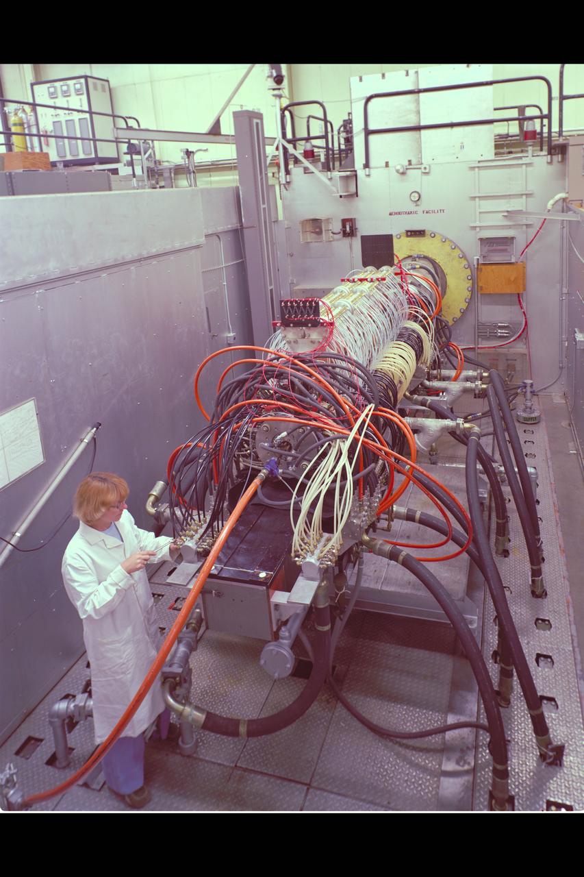
N-238 60MW Aerodynamic Heating Facility outside of test section with Jean Brian (Arc heater, high pressure water manifold, & water cooled 8' conical nozzle)

N-238 60MW Aerodynamic Heating Facility outside of test section with Jean Brian (Arch heater, high pressure water manifold, & water cooled 8' conical nozzle)
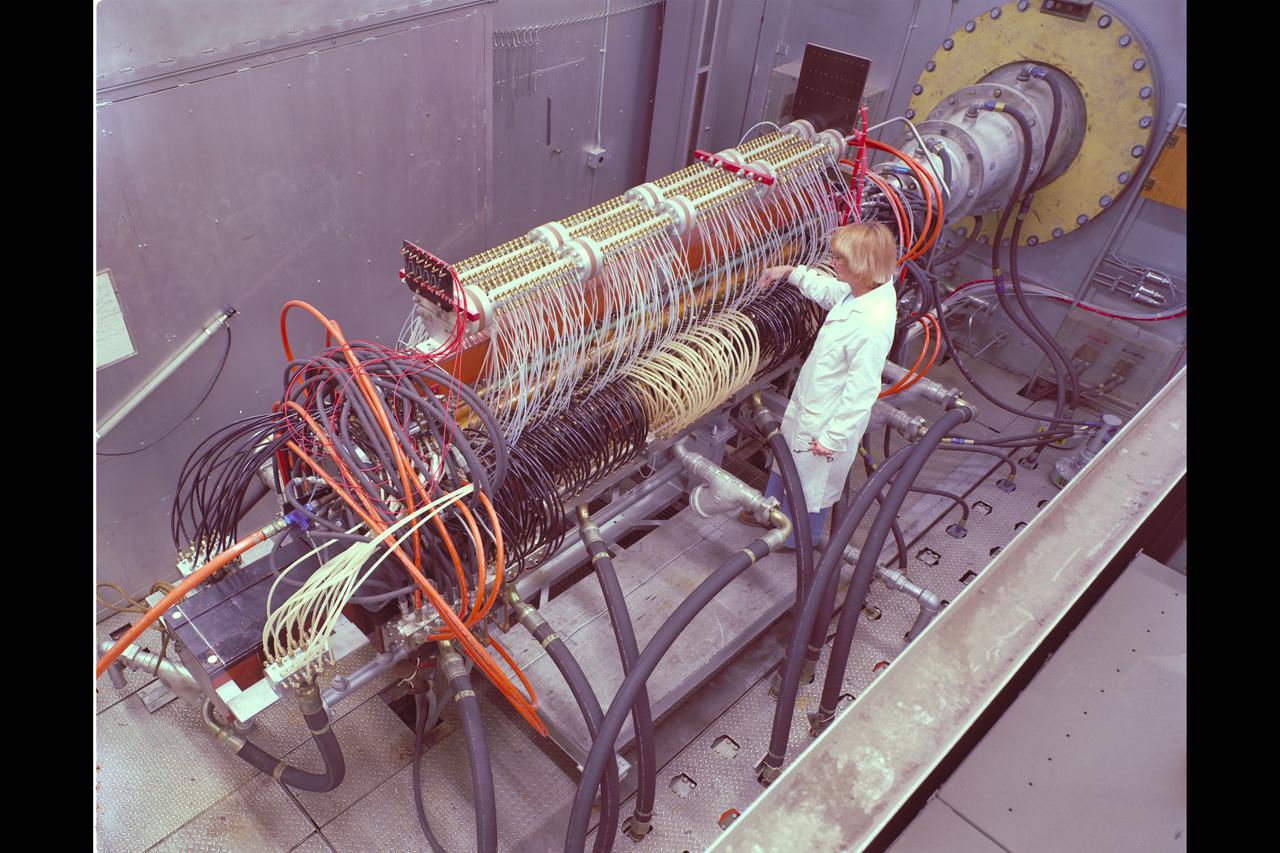
N-238 60MW Aerodynamic Heating Facility outside of test section with Jean Brian (Arc heater, high pressure water manifold, & water cooled 8' conical nozzle)
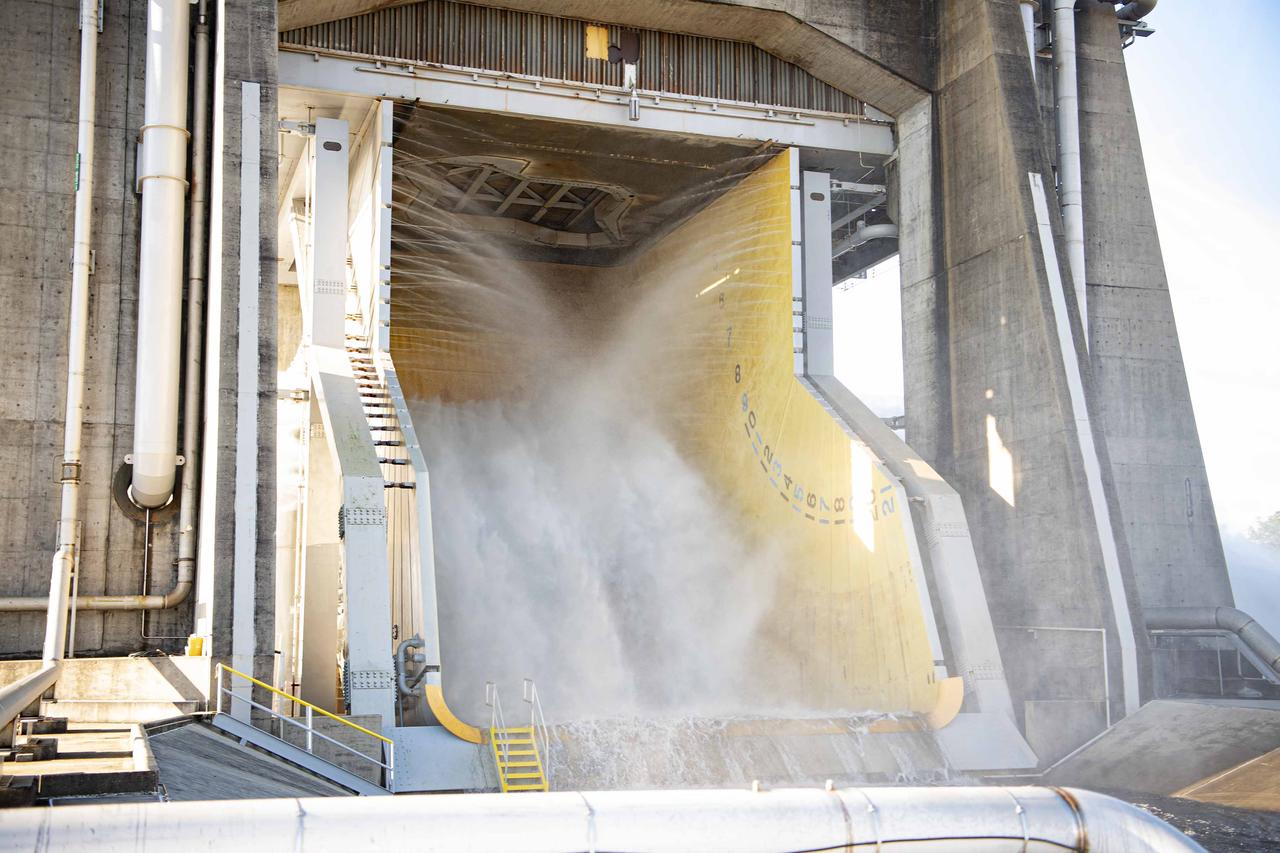
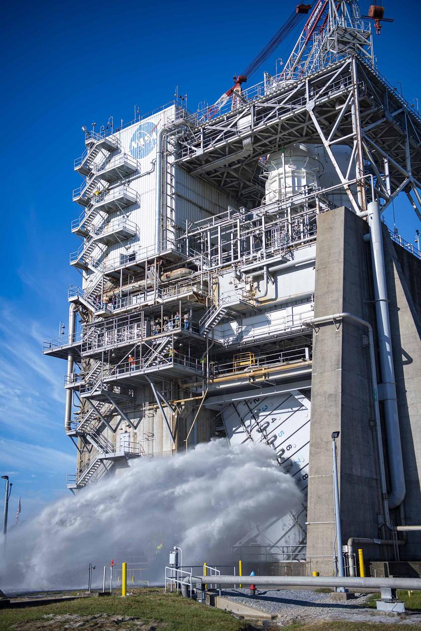
Crews conduct a planned flame deflector water flow system flush on the Fred Haise Test Stand at NASA’s Stennis Space Center on Oct. 22, following the recent completion of upgrades to the High Pressure Industrial Water Facility’s underground piping network. The flush, a periodic procedure to ensure system functionality and performance, involves flowing 150,000 gallons or more per minute from the High Pressure Industrial Water Facility to the stand. It also continues stand preparations for testing RS-25 flight engines for use on future Artemis missions to the Moon and beyond.
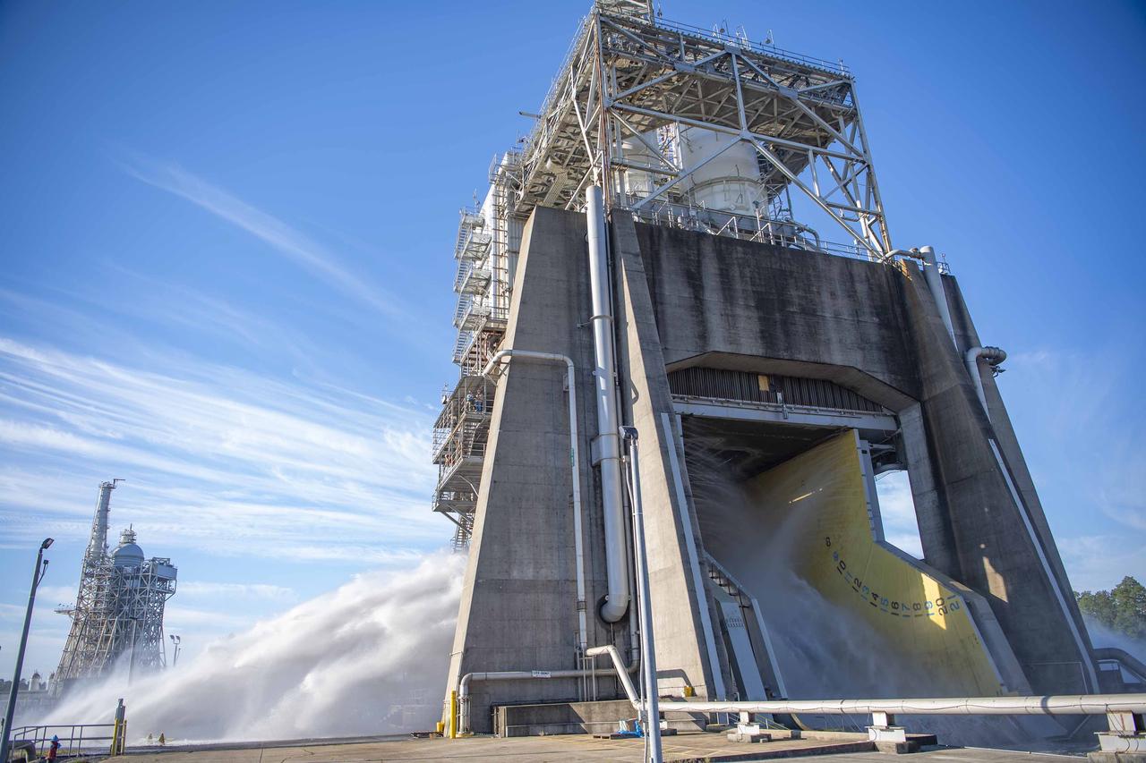
Crews conduct a planned flame deflector water flow system flush on the Fred Haise Test Stand at NASA’s Stennis Space Center on Oct. 22, following the recent completion of upgrades to the High Pressure Industrial Water Facility’s underground piping network. The flush, a periodic procedure to ensure system functionality and performance, involves flowing 150,000 gallons or more per minute from the High Pressure Industrial Water Facility to the stand. It also continues stand preparations for testing RS-25 flight engines for use on future Artemis missions to the Moon and beyond.
Crews conduct a planned flame deflector water flow system flush on the Fred Haise Test Stand at NASA’s Stennis Space Center on Oct. 22, following the recent completion of upgrades to the High Pressure Industrial Water Facility’s underground piping network. The flush, a periodic procedure to ensure system functionality and performance, involves flowing 150,000 gallons or more per minute from the High Pressure Industrial Water Facility to the stand. It also continues stand preparations for testing RS-25 flight engines for use on future Artemis missions to the Moon and beyond.

Crews conduct a planned flame deflector water flow system flush on the Fred Haise Test Stand at NASA’s Stennis Space Center on Oct. 22, following the recent completion of upgrades to the High Pressure Industrial Water Facility’s underground piping network. The flush, a periodic procedure to ensure system functionality and performance, involves flowing 150,000 gallons or more per minute from the High Pressure Industrial Water Facility to the stand. It also continues stand preparations for testing RS-25 flight engines for use on future Artemis missions to the Moon and beyond.
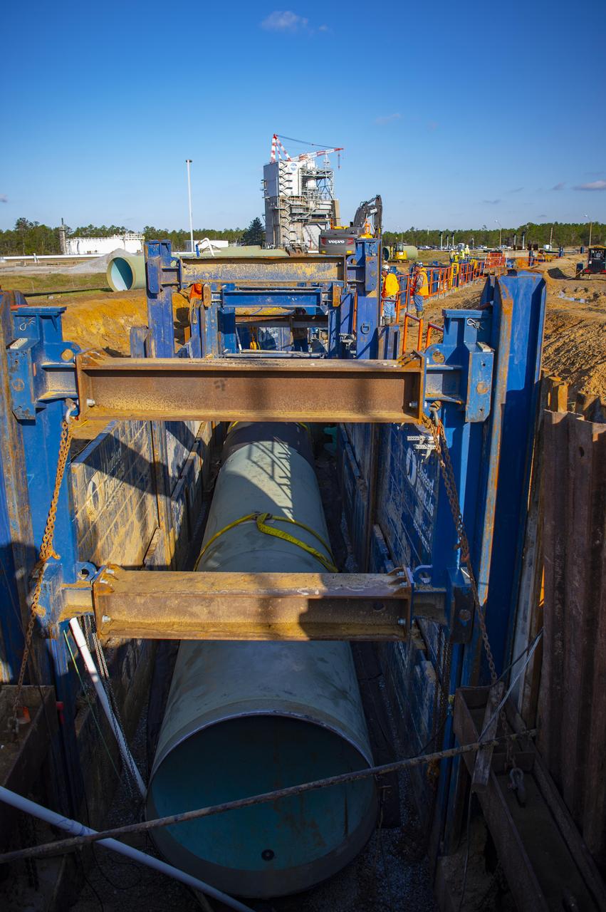
In this March 2022 photo, crews use a shoring system to hold back soil as they install new 75-inch piping leading from the NASA Stennis High Pressure Industrial Water Facility to the valve vault pit serving the Fred Haise Test Stand.
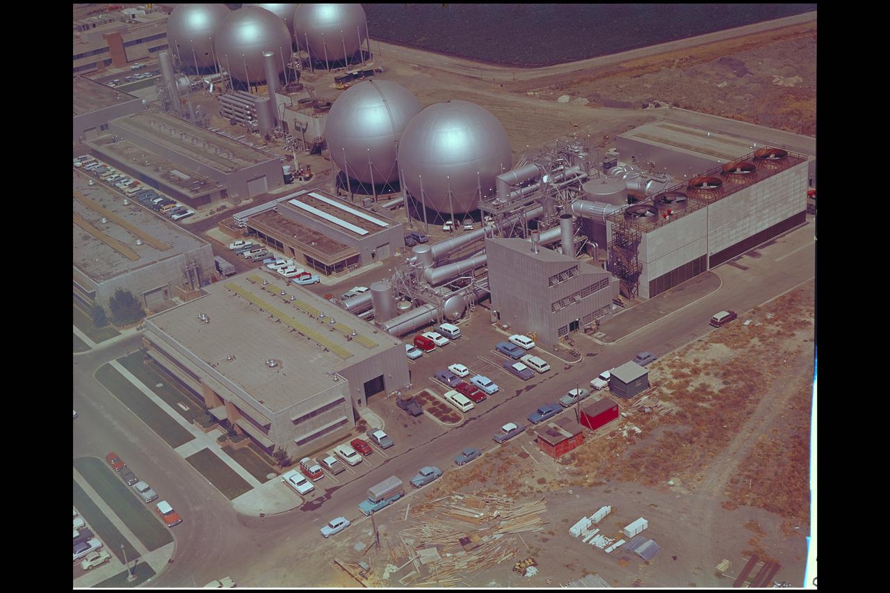
Aerial view of Gasdynamics facility in 1964 and the 20 inch helium tunnel Part of the Thermal Protection Laboratory used to research materials for heat shield applications and for aerodynamic heating and materials studies of vehicles in planetary atmospheres. This laboratory is comprised of five separate facilities: an Aerodynamic Heating Tunnel, a Heat Transfer Tunnel, two Supersonic Turbulent Ducts, and a High-Power CO2 Gasdynamic Laser. All these facilities are driven by arc-heaters, with the exception of the large, combustion-type laser. The arc-heated facilities are powered by a 20 Megawatt DC power supply. Their effluent gas stream (test gases; Air, N2, He, CO2 and mixtures; flow rates from 0.05 to 5.0 lbs/sec) discharges into a five-stage stream-ejector-driven vacuum system. The vacuum system and power supply are common to the test faciities in building N-238. All of the facilities have high pressure water available at flow rates up to 4, 000 gals/min. The data obtained from these facilities are recorded on magnetic tape or oscillographs. All forms of data can be handled whether from thermo-couples, pressure cells, pyrometers, or radiometers, etc. in addition, closed circuit T. V. monitors and various film cameras are available. (operational since 1962)
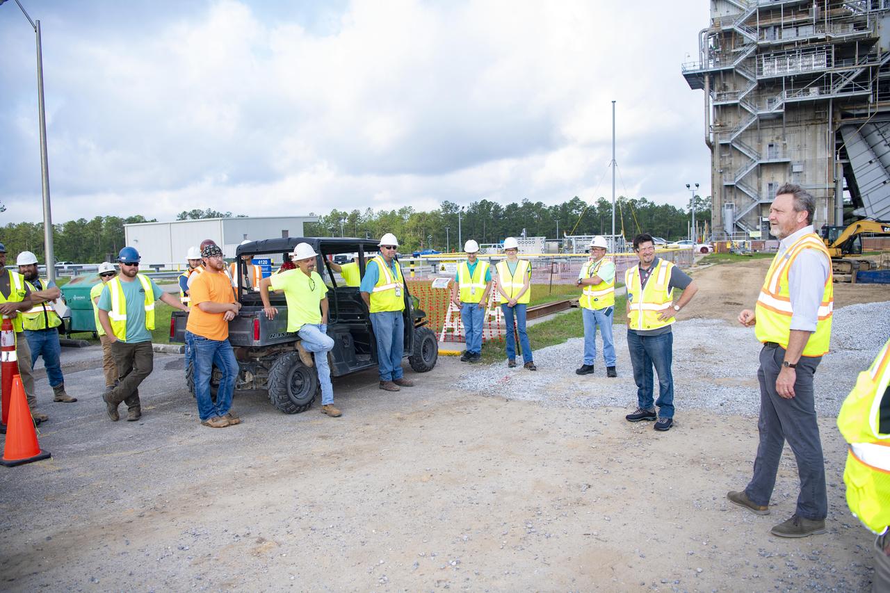
Rodney McKellip, associate director of NASA’s Stennis Space Center, and Gary Benton, director of the NASA Stennis Safety and Mission Assurance Directorate, are shown, from right to left, with employees working on the High Pressure Industrial Water Facility project near the Fred Haise Test Stand. The NASA Stennis leaders visited work sites on May 8 to recognize employees with NASA SHAKERS (Smart Human Actions Keep Everyone Really Safe) Awards for conducting work in a safe manner. NASA’s constant attention to safety, one of the agency’s five core values, is the cornerstone for mission success.
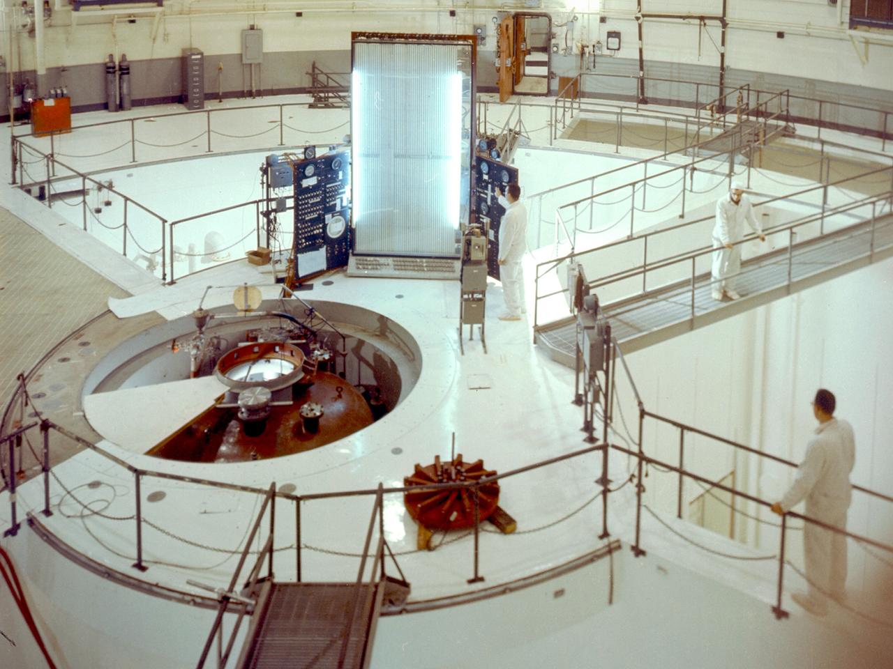
A view inside the 55-foot high containment vessel of the National Aeronautics and Space Administration (NASA) Plum Brook Reactor Facility in Sandusky, Ohio. The 60-megawatt test reactor went critical for the first time in 1961 and began its full-power research operations in 1963. From 1961 to 1973, this reactor performed some of the nation’s most advanced nuclear research. The reactor was designed to determine the behavior of metals and other materials after long durations of irradiation. The materials would be used to construct a nuclear-powered rocket. The reactor core, where the chain reaction occurred, sat at the bottom of the tubular pressure vessel, seen here at the center of the shielding pool. The core contained fuel rods with uranium isotopes. A cooling system was needed to reduce the heat levels during the reaction. A neutron-impervious reflector was also employed to send many of the neutrons back to the core. The Plum Brook Reactor Facility was constructed from high-density concrete and steel to prevent the excess neutrons from escaping the facility, but the water in the pool shielded most of the radiation. The water, found in three of the four quadrants served as a reflector, moderator, and coolant. In this photograph, the three 20-ton protective shrapnel shields and hatch have been removed from the top of the pressure tank revealing the reactor tank. An overhead crane could be manipulated to reach any section of this room. It was used to remove the shrapnel shields and transfer equipment.
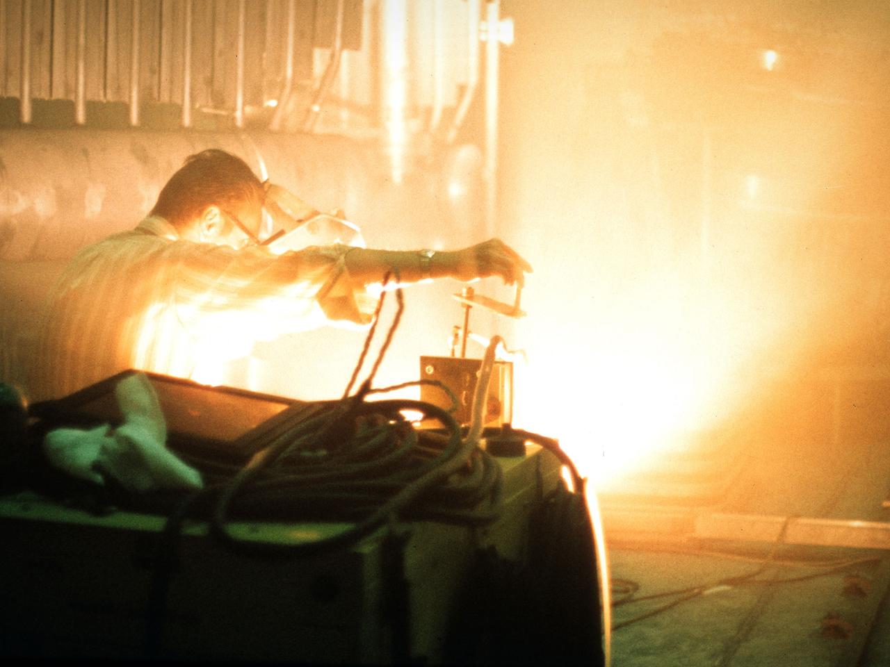
A researcher sets up equipment in the Space Power Chamber at National Aeronautics and Space Administration’s (NASA) Plum Brook Station to study the effects of contaminants on clouds. Drs. Rosa and Jorge Pena of Pennsylvania State University's Department of Meteorology initiated the program in an effort to develop methods of creating stable, long-lasting clouds in a test chamber in order to study their composition and formation. The researchers then wanted to use the artificially-created clouds to determine how they were affected by pollution. The 100-foot diameter and 122-foot high Space Power Chamber is the largest vacuum chamber in the world. The researchers covered the circular walls with muslin. A recirculating water system saturated the cloth. The facility engineers then reduced the chamber’s pressure which released the water from the muslin and generated a cloud. The researchers produced five different clouds in this first portion of this study. They discovered that they could not create stable clouds because of the heat generated by the water-pumping equipment. Nonetheless, they felt confident enough to commence planning the second phase of the program using a heat exchanger to cool the equipment.

These compressors inside the Refrigeration Building at the National Advisory Committee for Aeronautics (NACA) Aircraft Engine Research Laboratory were used to generate cold temperatures in the Altitude Wind Tunnel (AWT) and Icing Research Tunnel. The AWT was a large facility that simulated actual flight conditions at high altitudes. The two primary aspects of altitude simulation are the reduction of the air pressure and the decrease of temperature. The Icing Research Tunnel was a smaller facility in which water droplets were added to the refrigerated air stream to simulate weather conditions that produced ice buildup on aircraft. The military pressured the NACA to complete the tunnels quickly so they could be of use during World War II. The NACA engineers struggled with the design of this refrigeration system, so Willis Carrier, whose Carrier Corporation had pioneered modern refrigeration, took on the project. The Carrier engineers devised the largest cooling system of its kind in the world. The system could lower the tunnels’ air temperature to –47⁰ F. The cooling system was powered by 14 Carrier and York compressors, seen in this photograph, which were housed in the Refrigeration Building between the two wind tunnels. The compressors converted the Freon 12 refrigerant into a liquid. The refrigerant was then pumped into zig-zag banks of cooling coils inside the tunnels’ return leg. The Freon absorbed heat from the airflow as it passed through the coils. The heat was transferred to the cooling water and sent to the cooling tower where it was dissipated into the atmosphere.
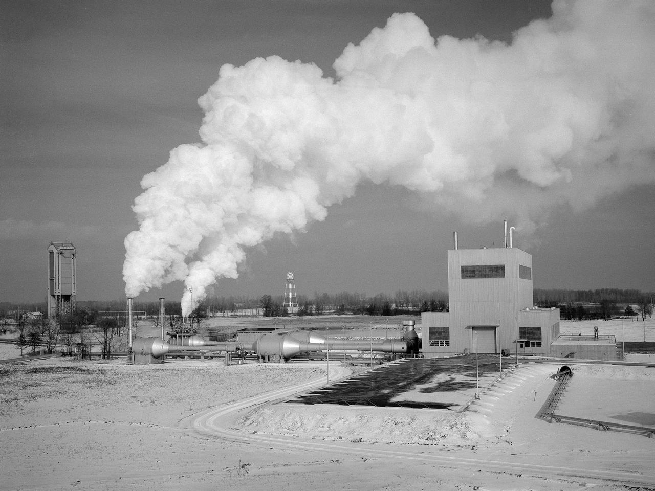
The Space Propulsion Research Facility, better known as B-2, operating at the National Aeronautics and Space Administration’s (NASA) Plum Brook Station in Sandusky, Ohio. B-2 is the world's only high altitude test facility capable of full-scale rocket engine and launch vehicle system level tests. It was created to test rocket propulsion systems with up to 100,000 pounds of thrust in a simulated space environment. The facility has the unique ability to maintain a vacuum at the rocket’s nozzle while the engine is firing. The rocket fires into a 120-foot deep spray chamber which cools the exhaust before it is ejected outside the facility. B-2 simulated space using giant diffusion pumps to reduce chamber pressure, nitrogen-filled cold walls create cryogenic temperatures, and quartz lamps replicate the radiation of the sun. This photograph shows the facility undergoing check-out runs prior to its first test in late 1969.The 38-foot diameter and 62-foot tall vacuum chamber is inside the high-bay on the right. Below that is a 67-foot diameter and 120-foot deep spray chamber. The hot rocket exhaust is cooled in the chamber by a spray of 250,000 gallons of water per minute. B-2’s first test was a hot firing of Centaur D-1A rocket on December 18, 1969. Since then the facility has fired more than 100 Pratt and Whitney RL-10 engines during the Centaur development, 80 current RL-10B-2 engines for Delta-3 development, and another 12 RL-10B-2s for the Delta 3 Upper Stage.

A mechanic works on a General Electric I-40 turbojet at the National Advisory Committee for Aeronautics (NACA) Lewis Flight Propulsion Laboratory. The military selected General Electric’s West Lynn facility in 1941 to secretly replicate the centrifugal turbojet engine designed by British engineer Frank Whittle. General Electric’s first attempt, the I-A, was fraught with problems. The design was improved somewhat with the subsequent I-16 engine. It was not until the engine's next reincarnation as the I-40 in 1943 that General Electric’s efforts paid off. The 4000-pound thrust I-40 was incorporated into the Lockheed Shooting Star airframe and successfully flown in June 1944. The Shooting Star became the US’s first successful jet aircraft and the first US aircraft to reach 500 miles per hour. The NACA’s Lewis Flight Propulsion Laboratory studied all of General Electric’s centrifugal turbojets both during World War II and afterwards. The entire Shooting Star aircraft was investigated in the Altitude Wind Tunnel during 1945. The researchers studied the engine compressor performance, thrust augmentation using a water injection, and compared different fuel blends in a single combustor. The mechanic in this photograph is inserting a combustion liner into one of the 14 combustor cans. The compressor, which is not yet installed in this photograph, pushed high pressure air into these combustors. There the air mixed with the fuel and was heated. The hot air was then forced through a rotating turbine that powered the engine before being expelled out the nozzle to produce thrust.