
Event: Horizontal Stabilator Install The Low Boom Flight Demonstrator manufacturing team installed the horizontal stabilizers to the aircraft. These are used along with the flight control computers to keep the airplane flying safely and providing the pitch control so that the pilot can fly the missions envisioned for the X-59

Event: Horizontal Stabilator Install The Low Boom Flight Demonstrator manufacturing team installed the horizontal stabilizers to the aircraft. These are used along with the flight control computers to keep the airplane flying safely and providing the pitch control so that the pilot can fly the missions envisioned for the X-59.

Event: Horizontal Stabilator Install The Low Boom Flight Demonstrator manufacturing team installed the horizontal stabilizers to the aircraft. These are used along with the flight control computers to keep the airplane flying safely and providing the pitch control so that the pilot can fly the missions envisioned for the X-59.

Event: Horizontal Stabilator Install The Low Boom Flight Demonstrator manufacturing team installed the horizontal stabilizers to the aircraft. These are used along with the flight control computers to keep the airplane flying safely and providing the pitch control so that the pilot can fly the missions envisioned for the X-59.
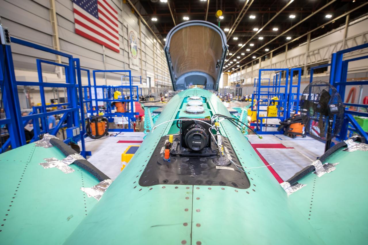
Event: Horizontal Stabilator Install A close up of the camera from the X-59’s eXternal Vision System. This camera is on the top of the X-59, but there will also be one on the belly of the aircraft. This visuals from this camera will be displayed on a 4K monitor for the pilot. As part of the supersonic shaping technology, the X-plane will not have a forward-facing window in the cockpit.
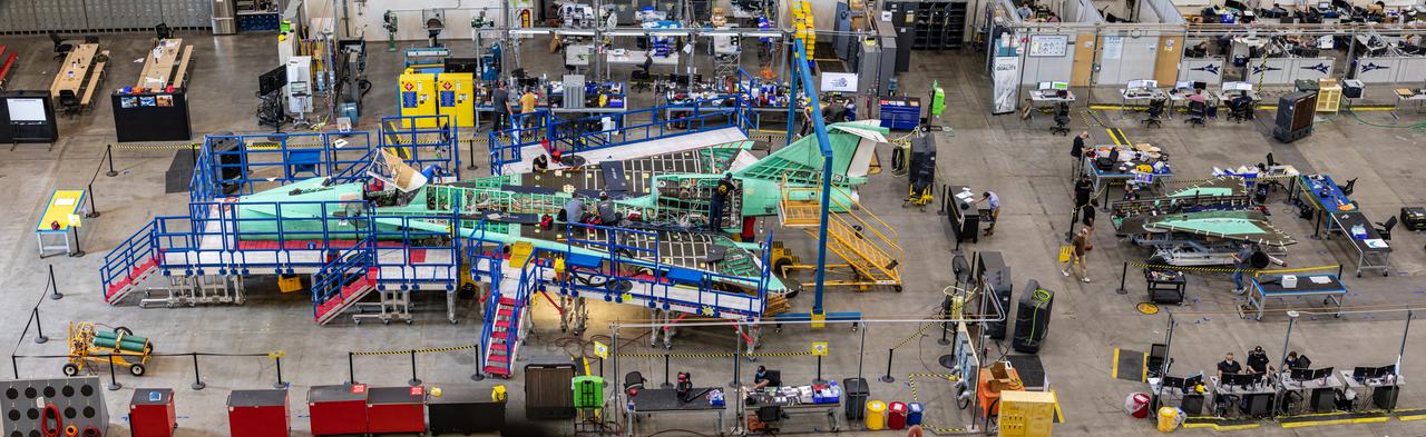
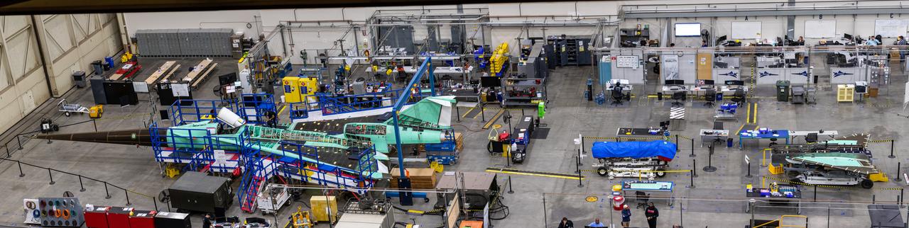
This overhead view of the X-59 shows the aircraft at Lockheed Martin Skunk Works in Palmdale, California. During the assembly of this experimental aircraft, the team often has to remove components to effectively and safely assemble other sections of the aircraft. In this image, the nose is not attached and the horizontal stabilators are shown behind the tail. The X-59 is the centerpiece of NASA’s Quesst mission which plans to produce data that will help enable commercial supersonic air travel over land.

This overhead view of the X-59 shows the aircraft at Lockheed Martin Skunk Works in Palmdale, California. During the assembly of this experimental aircraft, the team often has to remove components to effectively and safely assemble other sections of the aircraft. In this image, the nose is not attached and the horizontal stabilators are shown behind the tail. The X-59 is the centerpiece of NASA’s Quesst mission which plans to produce data that will help enable commercial supersonic air travel over land.
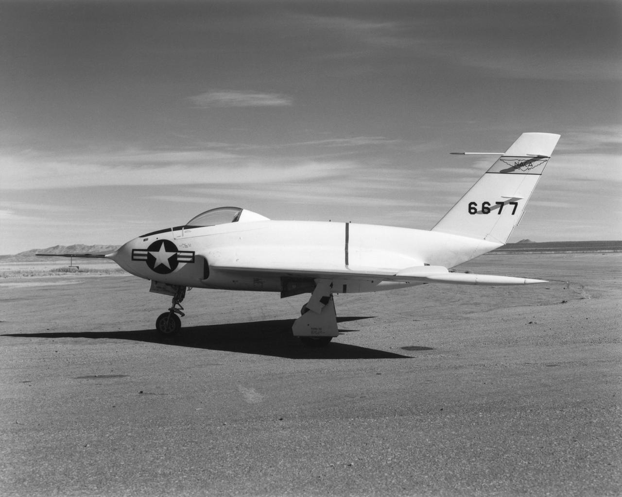
In this 1950 view of the left side of the NACA High-Speed Flight Research Station's X-4 research aircraft, the low swept wing and horizontal taillest design are seen. The X-4 Bantam, a single-place, low swept-wing, semi-tailless aircraft, was designed and built by Northrop Aircraft, Inc. It had no horizontal tail surfaces and its mission was to obtain in-flight data on the stability and control of semi-tailless aircraft at high subsonic speeds.
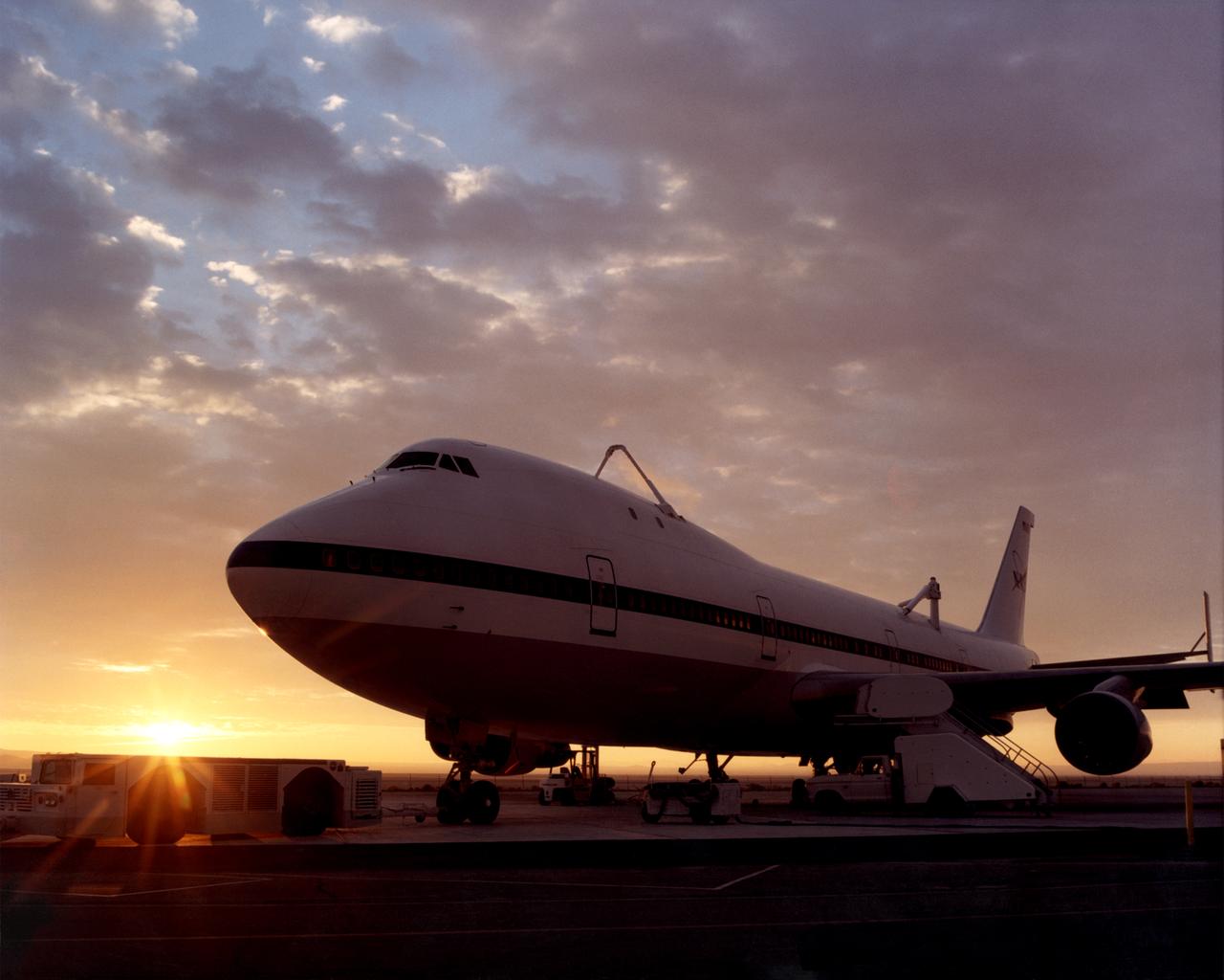
One of NASA’s two modified Boeing 747 Shuttle Carrier Aircraft is bathed in the morning Sun at NASA’s Dryden Flight Research Center at Edwards, California. The modified jumbo jetliners are used to ferry the Space Shuttle orbiters between Dryden and the Kennedy Space Center in Florida and Boeing’s Reusable Space Systems modification facility at Palmdale, California. Features which distinguish the two SCAs from standard 747 jetliners are three struts, with associated interior structural strengthening, which protrude from the top of the fuselage (two aft, one forward) on which the orbiter is attached, and two additional vertical stabilizers, one on each end of the standard horizontal stabilizer, to enhance directional stability. All interior furnishings and equipment aft of the forward No. 1 doors have also been removed to reduce weight. The two SCAs are under the operational control of NASA's Johnson Space Center, Houston, Texas.
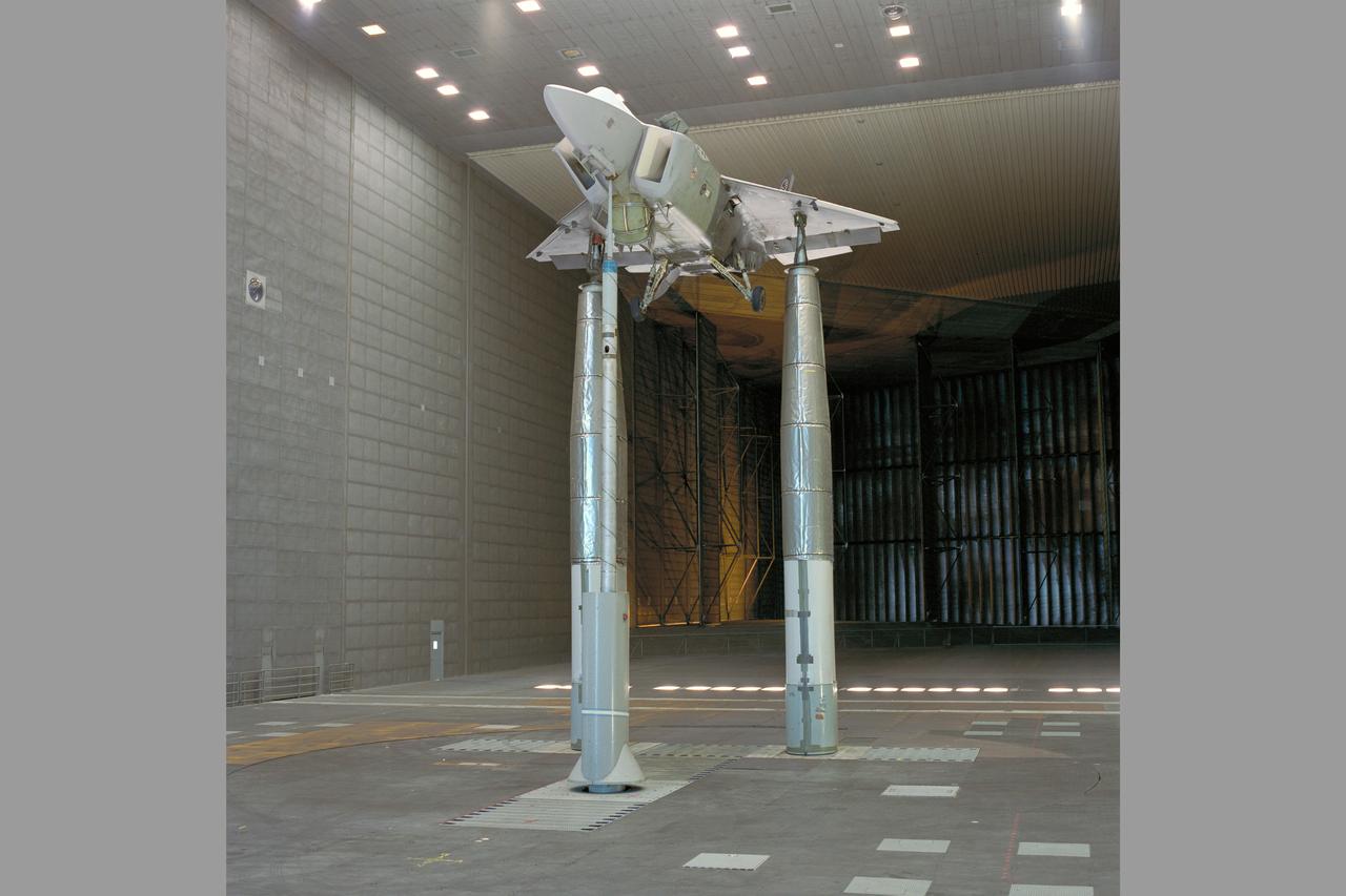
CALF/JAST X-32 test program: the LSPM (Large Scale Powered Model), Lockheed's concept for a tri-service aircraft (Air Force, Navy, Marines) CALF (Common Affordable Lightweight Fighter) as part of the Department of Defense's Joint Advanced Strike Technology (JAST) is being tested in the 80x120ft w.t. test-930 with rear horizontal stabilizer

Two scientists at NASA Marshall Space Flight Center, atmospheric scientist Paul Meyer (left) and solar physicist Dr. David Hathaway, have developed promising new software, called Video Image Stabilization and Registration (VISAR), that may help law enforcement agencies to catch criminals by improving the quality of video recorded at crime scenes, VISAR stabilizes camera motion in the horizontal and vertical as well as rotation and zoom effects; produces clearer images of moving objects; smoothes jagged edges; enhances still images; and reduces video noise of snow. VISAR could also have applications in medical and meteorological imaging. It could steady images of Ultrasounds which are infamous for their grainy, blurred quality. It would be especially useful for tornadoes, tracking whirling objects and helping to determine the tornado's wind speed. This image shows two scientists reviewing an enhanced video image of a license plate taken from a moving automobile.
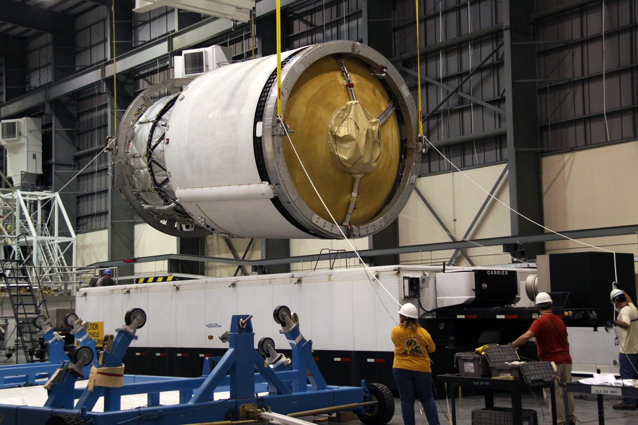
CAPE CANAVERAL, Fla. – Workers stabilize the second stage of a Delta IV as it is lifted by crane from its transporter in the Horizontal Integration Facility at Launch Complex 37 on Cape Canaveral Air Force Station in Florida. This United Launch Alliance Delta IV rocket is the vehicle slated to launch GOES-P, the latest Geostationary Operational Environmental Satellite developed by NASA for the National Oceanic and Atmospheric Administration, or NOAA. Processing of the Delta IV is on track for launch, targeted for March 4, 2010. For information on GOES-P, visit http://goespoes.gsfc.nasa.gov/goes/spacecraft/n_p_spacecraft.html. Photo credit: NASA/Jack Pfaller

Two scientists at NASA's Marshall Space Flight Center,atmospheric scientist Paul Meyer and solar physicist Dr. David Hathaway, developed promising new software, called Video Image Stabilization and Registration (VISAR). VISAR may help law enforcement agencies catch criminals by improving the quality of video recorded at crime scenes. In this photograph, the single frame at left, taken at night, was brightened in order to enhance details and reduce noise or snow. To further overcome the video defects in one frame, Law enforcement officials can use VISAR software to add information from multiple frames to reveal a person. Images from less than a second of videotape were added together to create the clarified image at right. VISAR stabilizes camera motion in the horizontal and vertical as well as rotation and zoom effects producing clearer images of moving objects, smoothes jagged edges, enhances still images, and reduces video noise or snow. VISAR could also have applications in medical and meteorological imaging. It could steady images of ultrasounds, which are infamous for their grainy, blurred quality. The software can be used for defense application by improving recornaissance video imagery made by military vehicles, aircraft, and ships traveling in harsh, rugged environments.
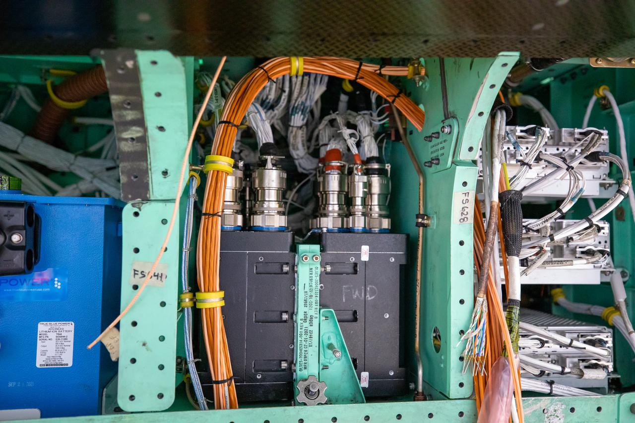
This is a closeup view of the inner workings of the X-59 aircraft. Visible are one the plane’s three lithium-ion batteries (blue box), electrical power system and other wiring components including the vehicle management systems computers (two black boxes) and the white wirings which assist in providing the power that is needed for the aircraft to function in flight. All of these components are essential to maintaining and monitoring the X-59 once it takes to the skies. The X-59 is the centerpiece of the Quesst mission which plans to help enable commercial supersonic air travel over land.

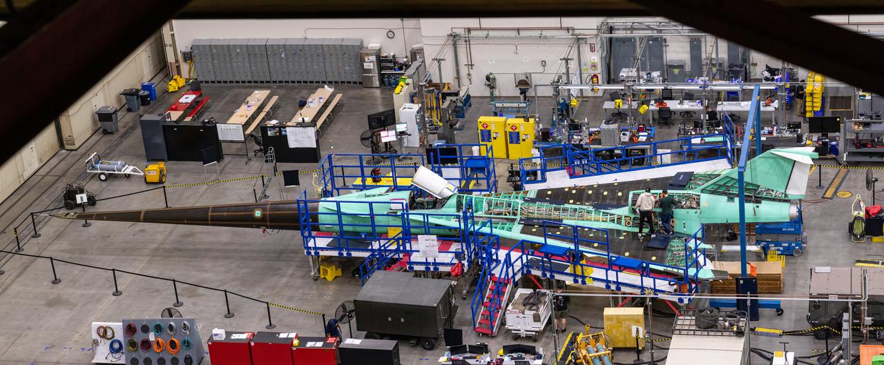
This overhead view of the X-59 shows the aircraft’s current state of assembly at Lockheed Martin Skunk Works in Palmdale, California. Throughout the manufacturing process, the team often removes components to effectively and safely assemble other sections of the aircraft. The X-59’s horizontal tails and lower empennage were recently removed from the aircraft and can be seen behind it as the team prepares for the installation of the engine. The X-59 is the centerpiece of the Quesst mission which plans to help enable commercial supersonic air travel over land.
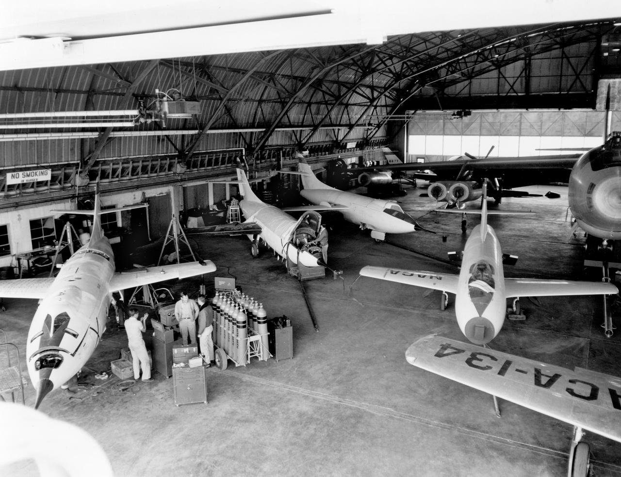
The aircraft in this 1953 photo of the National Advisory Committee for Aeronautics (NACA) hangar at South Base of Edwards Air Force Base showed the wide range of research activities being undertaken. On the left side of the hangar are the three D-558-2 research aircraft. These were designed to test swept wings at supersonic speeds approaching Mach 2. The front D-558-2 is the third built (NACA 145/Navy 37975). It has been modified with a leading-edge chord extension. This was one of a number of wing modifications, using different configurations of slats and/or wing fences, to ease the airplane's tendency to pitch-up. NACA 145 had both a jet and a rocket engine. The middle aircraft is NACA 144 (Navy 37974), the second built. It was all-rocket powered, and Scott Crossfield made the first Mach 2 flight in this aircraft on November 20, 1953. The aircraft in the back is D-558-2 number 1. NACA 143 (Navy 37973) was also carried both a jet and a rocket engine in 1953. It had been used for the Douglas contractor flights, then was turned over to the NACA. The aircraft was not converted to all-rocket power until June 1954. It made only a single NACA flight before NACA's D-558-2 program ended in 1956. Beside the three D-558-2s is the third D-558-1. Unlike the supersonic D-558-2s, it was designed for flight research at transonic speeds, up to Mach 1. The D-558-1 was jet-powered, and took off from the ground. The D-558-1's handling was poor as it approached Mach 1. Given the designation NACA 142 (Navy 37972), it made a total of 78 research flights, with the last in June 1953. In the back of the hangar is the X-4 (Air Force 46-677). This was a Northrop-built research aircraft which tested a swept wing design without horizontal stabilizers. The aircraft proved unstable in flight at speeds above Mach 0.88. The aircraft showed combined pitching, rolling, and yawing motions, and the design was considered unsuitable. The aircraft, the second X-4 built, was then used as a pilot traine
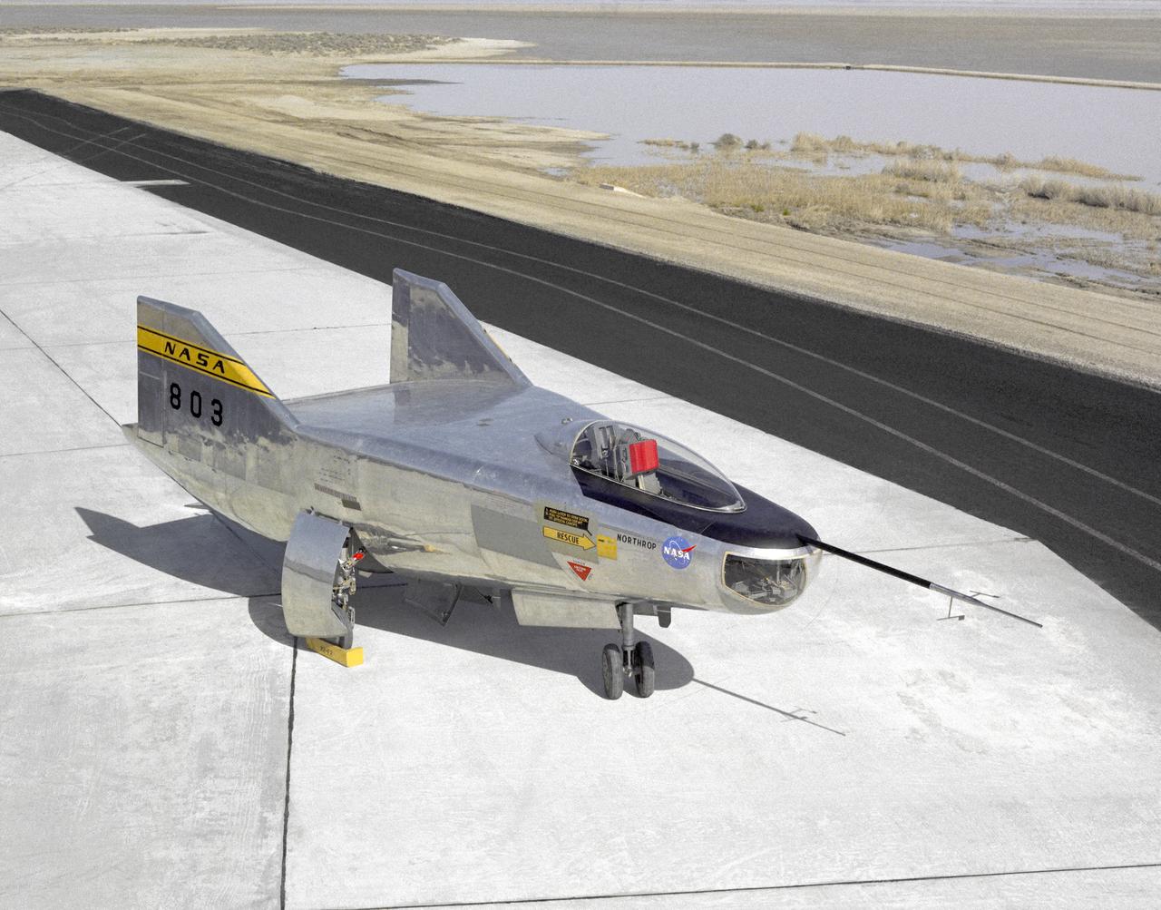
The M2-F2 Lifting Body is seen here on the ramp at the NASA Dryden Flight Research Center. The success of Dryden's M2-F1 program led to NASA's development and construction of two heavyweight lifting bodies based on studies at NASA's Ames and Langley research centers -- the M2-F2 and the HL-10, both built by the Northrop Corporation. The "M" refers to "manned" and "F" refers to "flight" version. "HL" comes from "horizontal landing" and 10 is for the tenth lifting body model to be investigated by Langley. The first flight of the M2-F2 -- which looked much like the "F1" -- was on July 12, 1966. Milt Thompson was the pilot. By then, the same B-52 used to air launch the famed X-15 rocket research aircraft was modified to also carry the lifting bodies. Thompson was dropped from the B-52's wing pylon mount at an altitude of 45,000 feet on that maiden glide flight. The M2-F2 weighed 4,620 pounds, was 22 feet long, and had a width of about 10 feet. On May 10, 1967, during the sixteenth glide flight leading up to powered flight, a landing accident severely damaged the vehicle and seriously injured the NASA pilot, Bruce Peterson. NASA pilots and researchers realized the M2-F2 had lateral control problems, even though it had a stability augmentation control system. When the M2-F2 was rebuilt at Dryden and redesignated the M2-F3, it was modified with an additional third vertical fin -- centered between the tip fins -- to improve control characteristics. The M2-F2/F3 was the first of the heavy-weight, entry-configuration lifting bodies. Its successful development as a research test vehicle answered many of the generic questions about these vehicles. NASA donated the M2-F3 vehicle to the Smithsonian Institute in December 1973. It is currently hanging in the Air and Space Museum along with the X-15 aircraft number 1, which was its hangar partner at Dryden from 1965 to 1969.
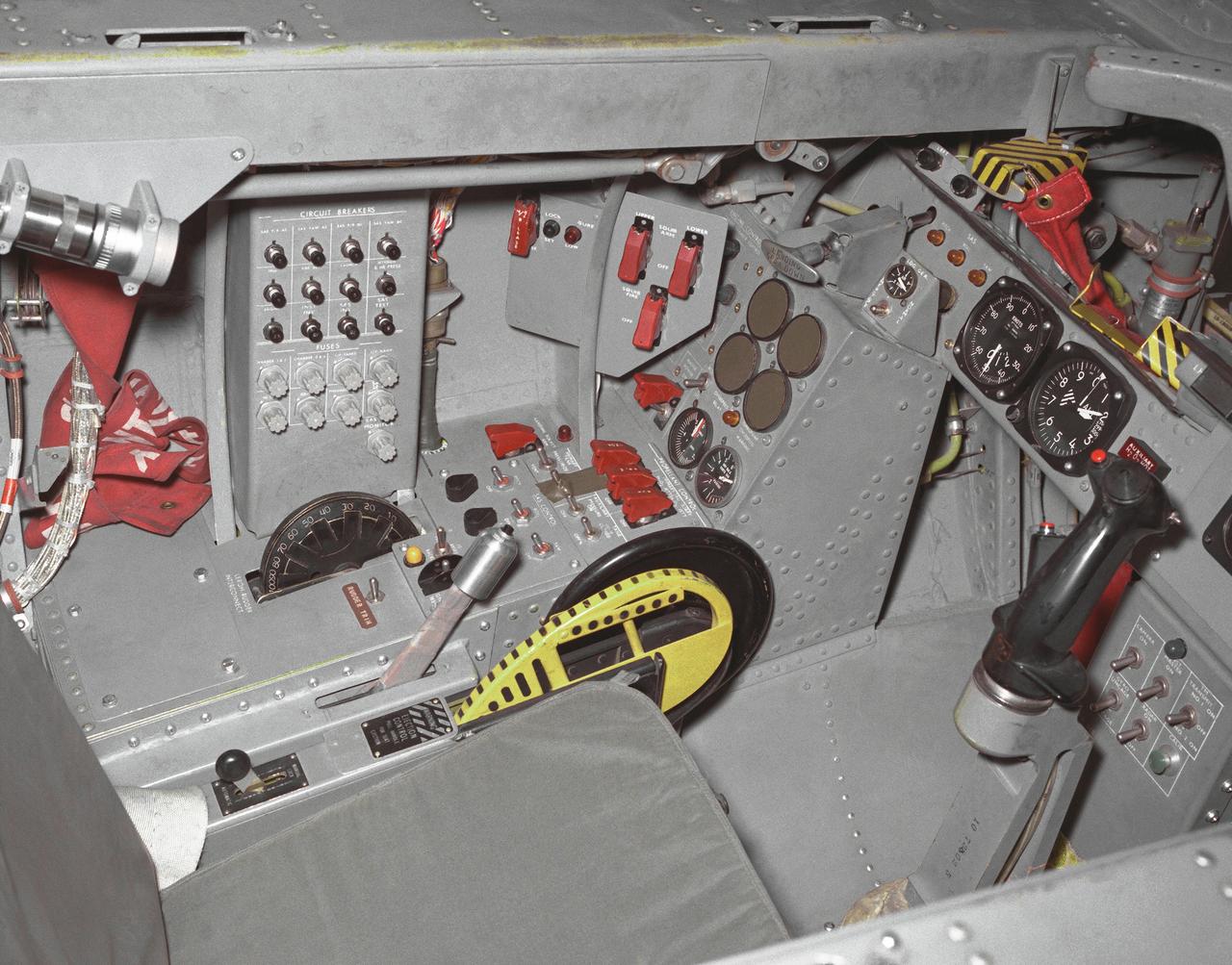
This photo shows the left side cockpit instrumentation panel of the M2-F2 Lifting Body. The success of Dryden's M2-F1 program led to NASA's development and construction of two heavyweight lifting bodies based on studies at NASA's Ames and Langley research centers -- the M2-F2 and the HL-10, both built by the Northrop Corporation. The "M" refers to "manned" and "F" refers to "flight" version. "HL" comes from "horizontal landing" and 10 is for the tenth lifting body model to be investigated by Langley. The first flight of the M2-F2 -- which looked much like the "F1" -- was on July 12, 1966. Milt Thompson was the pilot. By then, the same B-52 used to air launch the famed X-15 rocket research aircraft was modified to also carry the lifting bodies. Thompson was dropped from the B-52's wing pylon mount at an altitude of 45,000 feet on that maiden glide flight. The M2-F2 weighed 4,620 pounds, was 22 feet long, and had a width of about 10 feet. On May 10, 1967, during the sixteenth glide flight leading up to powered flight, a landing accident severely damaged the vehicle and seriously injured the NASA pilot, Bruce Peterson. NASA pilots and researchers realized the M2-F2 had lateral control problems, even though it had a stability augmentation control system. When the M2-F2 was rebuilt at Dryden and redesignated the M2-F3, it was modified with an additional third vertical fin -- centered between the tip fins -- to improve control characteristics. The M2-F2/F3 was the first of the heavy-weight, entry-configuration lifting bodies. Its successful development as a research test vehicle answered many of the generic questions about these vehicles. NASA donated the M2-F3 vehicle to the Smithsonian Institute in December 1973. It is currently hanging in the Air and Space Museum along with the X-15 aircraft number 1, which was its hangar partner at Dryden from 1965 to 1969.
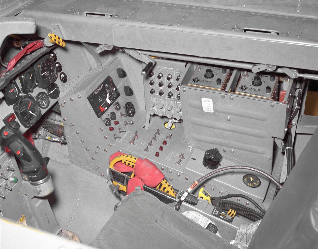
This photo shows the right side cockpit instrumentation panel of the M2-F2 Lifting Body. The success of Dryden's M2-F1 program led to NASA's development and construction of two heavyweight lifting bodies based on studies at NASA's Ames and Langley research centers -- the M2-F2 and the HL-10, both built by the Northrop Corporation. The "M" refers to "manned" and "F" refers to "flight" version. "HL" comes from "horizontal landing" and 10 is for the tenth lifting body model to be investigated by Langley. The first flight of the M2-F2 -- which looked much like the "F1" -- was on July 12, 1966. Milt Thompson was the pilot. By then, the same B-52 used to air launch the famed X-15 rocket research aircraft was modified to also carry the lifting bodies. Thompson was dropped from the B-52's wing pylon mount at an altitude of 45,000 feet on that maiden glide flight. The M2-F2 weighed 4,620 pounds, was 22 feet long, and had a width of about 10 feet. On May 10, 1967, during the sixteenth glide flight leading up to powered flight, a landing accident severely damaged the vehicle and seriously injured the NASA pilot, Bruce Peterson. NASA pilots and researchers realized the M2-F2 had lateral control problems, even though it had a stability augmentation control system. When the M2-F2 was rebuilt at Dryden and redesignated the M2-F3, it was modified with an additional third vertical fin -- centered between the tip fins -- to improve control characteristics. The M2-F2/F3 was the first of the heavy-weight, entry-configuration lifting bodies. Its successful development as a research test vehicle answered many of the generic questions about these vehicles. NASA donated the M2-F3 vehicle to the Smithsonian Institute in December 1973. It is currently hanging in the Air and Space Museum along with the X-15 aircraft number 1, which was its hangar partner at Dryden from 1965 to 1969.
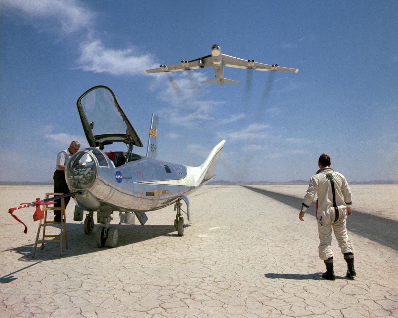
The HL-10 was one of five heavyweight lifting-body designs flown at NASA's Flight Research Center (FRC--later Dryden Flight Research Center), Edwards, California, from July 1966 to November 1975 to study and validate the concept of safely maneuvering and landing a low lift-over-drag vehicle designed for reentry from space. Northrop Corporation built the HL-10 and M2-F2, the first two of the fleet of "heavy" lifting bodies flown by the NASA Flight Research Center. The contract for construction of the HL-10 and the M2-F2 was $1.8 million. "HL" stands for horizontal landing, and "10" refers to the tenth design studied by engineers at NASA's Langley Research Center, Hampton, Va. After delivery to NASA in January 1966, the HL-10 made its first flight on Dec. 22, 1966, with research pilot Bruce Peterson in the cockpit. Although an XLR-11 rocket engine was installed in the vehicle, the first 11 drop flights from the B-52 launch aircraft were powerless glide flights to assess handling qualities, stability, and control. In the end, the HL-10 was judged to be the best handling of the three original heavy-weight lifting bodies (M2-F2/F3, HL-10, X-24A). The HL-10 was flown 37 times during the lifting body research program and logged the highest altitude and fastest speed in the Lifting Body program. On Feb. 18, 1970, Air Force test pilot Peter Hoag piloted the HL-10 to Mach 1.86 (1,228 mph). Nine days later, NASA pilot Bill Dana flew the vehicle to 90,030 feet, which became the highest altitude reached in the program. Some new and different lessons were learned through the successful flight testing of the HL-10. These lessons, when combined with information from it's sister ship, the M2-F2/F3, provided an excellent starting point for designers of future entry vehicles, including the Space Shuttle.
Here is an overhead view of the X-59 aircraft (left) prior to the installation of the General Electric F414 engine (center, located under the blue cover). After the engine is installed, the lower empennage (right), the last remaining major aircraft component, will be installed in preparation for integrated system checkouts. The X-59 is the centerpiece of the Quesst mission which plans to help enable commercial supersonic air travel over land.
This is an overhead view of the X-59 aircraft at Lockheed Martin Skunk Works in Palmdale, California. The nose was installed, and the plane awaits engine installation. Technicians continue to wire the aircraft as the team preforms several system checkouts to ensure the safety of the aircraft. The X-59 aircraft will demonstrate the ability to fly supersonic while reducing the loud sonic boom to a quiet sonic thump and help enable commercial supersonic air travel over land.

The Bell Aircraft Corporation X-1-2 aircraft on the ramp at NACA High Speed Flight Research Station located on the South Base of Muroc Army Air Field in 1947. The X-1-2 flew until October 23, 1951, completing 74 glide and powered flights with nine different pilots. The aircraft has white paint and the NACA tail band. The black Xs are reference markings for tracking purposes. They were widely used on NACA aircraft in the early 1950s.
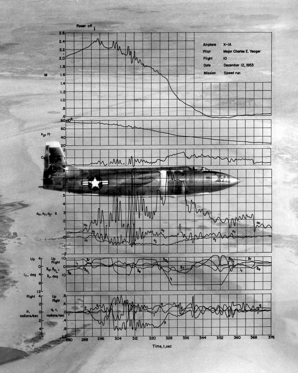
This photo of the X-1A includes graphs of the flight data from Maj. Charles E. Yeager's Mach 2.44 flight on December 12, 1953. (This was only a few days short of the 50th anniversary of the Wright brothers' first powered flight.) After reaching Mach 2.44, then the highest speed ever reached by a piloted aircraft, the X-1A tumbled completely out of control. The motions were so violent that Yeager cracked the plastic canopy with his helmet. He finally recovered from a inverted spin and landed on Rogers Dry Lakebed. Among the data shown are Mach number and altitude (the two top graphs). The speed and altitude changes due to the tumble are visible as jagged lines. The third graph from the bottom shows the G-forces on the airplane. During the tumble, these twice reached 8 Gs or 8 times the normal pull of gravity at sea level. (At these G forces, a 200-pound human would, in effect, weigh 1,600 pounds if a scale were placed under him in the direction of the force vector.) Producing these graphs was a slow, difficult process. The raw data from on-board instrumentation recorded on oscillograph film. Human computers then reduced the data and recorded it on data sheets, correcting for such factors as temperature and instrument errors. They used adding machines or slide rules for their calculations, pocket calculators being 20 years in the future.