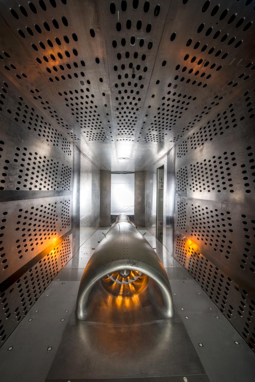
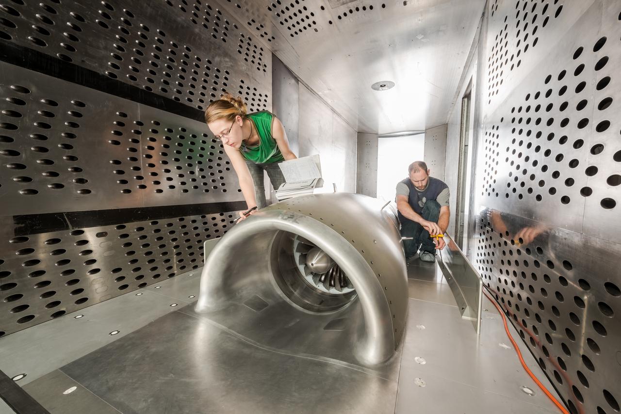
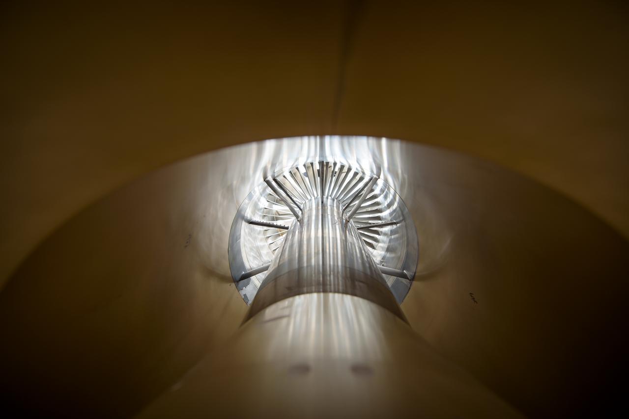
Fundamental Study of a boundary layer ingesting (BLI) propulsion model
SUPERSONIC SHORT TAKE OFF Vertical LANDING HOT GAS INGESTION MODEL 9X15 WIND TUNNEL
Supersonic Short Take Off Vertical Landing Hot Gas Ingestion Model Testing in the 9x15-foot Low Speed Wind Tunnel, LSWT
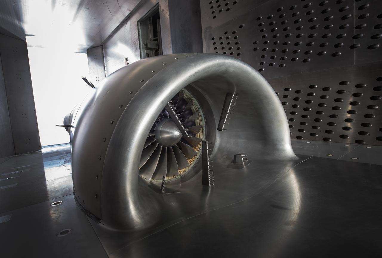
In an effort to improve fuel efficiency, NASA and the aircraft industry are rethinking aircraft design. Inside the 8' x 6' wind tunnel at NASA Glenn, engineers recently tested a fan and inlet design, commonly called a propulsor, which could use four to eight percent less fuel than today's advanced aircraft.
In an effort to improve fuel efficiency, NASA and the aircraft industry are rethinking aircraft design. Inside the 8' x 6' wind tunnel at NASA Glenn, engineers recently tested a fan and inlet design, commonly called a propulsor, which could use four to eight percent less fuel than today's advanced aircraft.
In an effort to improve fuel efficiency, NASA and the aircraft industry are rethinking aircraft design. Inside the 8' x 6' wind tunnel at NASA Glenn, engineers recently tested a fan and inlet design, commonly called a propulsor, which could use four to eight percent less fuel than today's advanced aircraft.
In an effort to improve fuel efficiency, NASA and the aircraft industry are rethinking aircraft design. Inside the 8' x 6' wind tunnel at NASA Glenn, engineers recently tested a fan and inlet design, commonly called a propulsor, which could use four to eight percent less fuel than today's advanced aircraft.
In an effort to improve fuel efficiency, NASA and the aircraft industry are rethinking aircraft design. Inside the 8' x 6' wind tunnel at NASA Glenn, engineers recently tested a fan and inlet design, commonly called a propulsor, which could use four to eight percent less fuel than today's advanced aircraft.
In an effort to improve fuel efficiency, NASA and the aircraft industry are rethinking aircraft design. Inside the 8' x 6' wind tunnel at NASA Glenn, engineers recently tested a fan and inlet design, commonly called a propulsor, which could use four to eight percent less fuel than today's advanced aircraft.
In an effort to improve fuel efficiency, NASA and the aircraft industry are rethinking aircraft design. Inside the 8' x 6' wind tunnel at NASA Glenn, engineers recently tested a fan and inlet design, commonly called a propulsor, which could use four to eight percent less fuel than today's advanced aircraft.

In an effort to improve fuel efficiency, NASA and the aircraft industry are rethinking aircraft design. Inside the 8' x 6' wind tunnel at NASA Glenn, engineers recently tested a fan and inlet design, commonly called a propulsor, which could use four to eight percent less fuel than today's advanced aircraft.

In an effort to improve fuel efficiency, NASA and the aircraft industry are rethinking aircraft design. Inside the 8' x 6' wind tunnel at NASA Glenn, engineers recently tested a fan and inlet design, commonly called a propulsor, which could use four to eight percent less fuel than today's advanced aircraft.
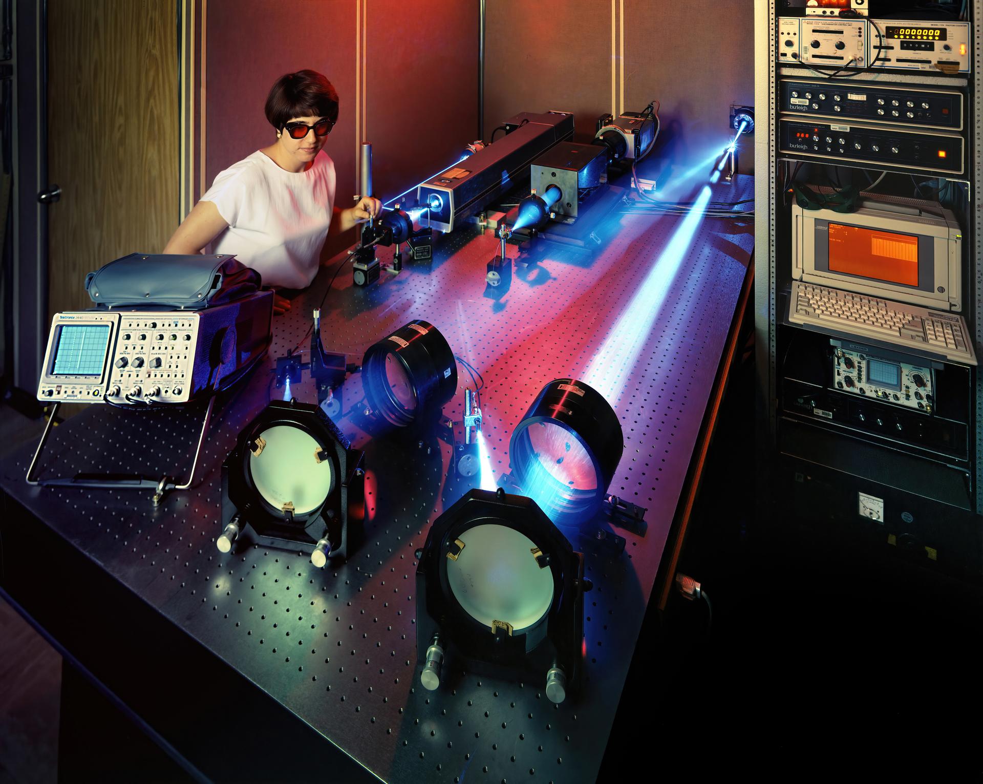
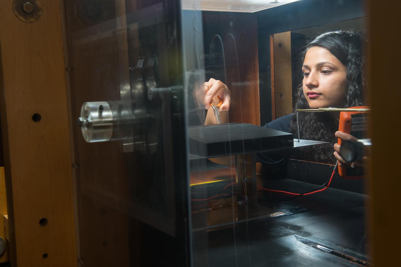
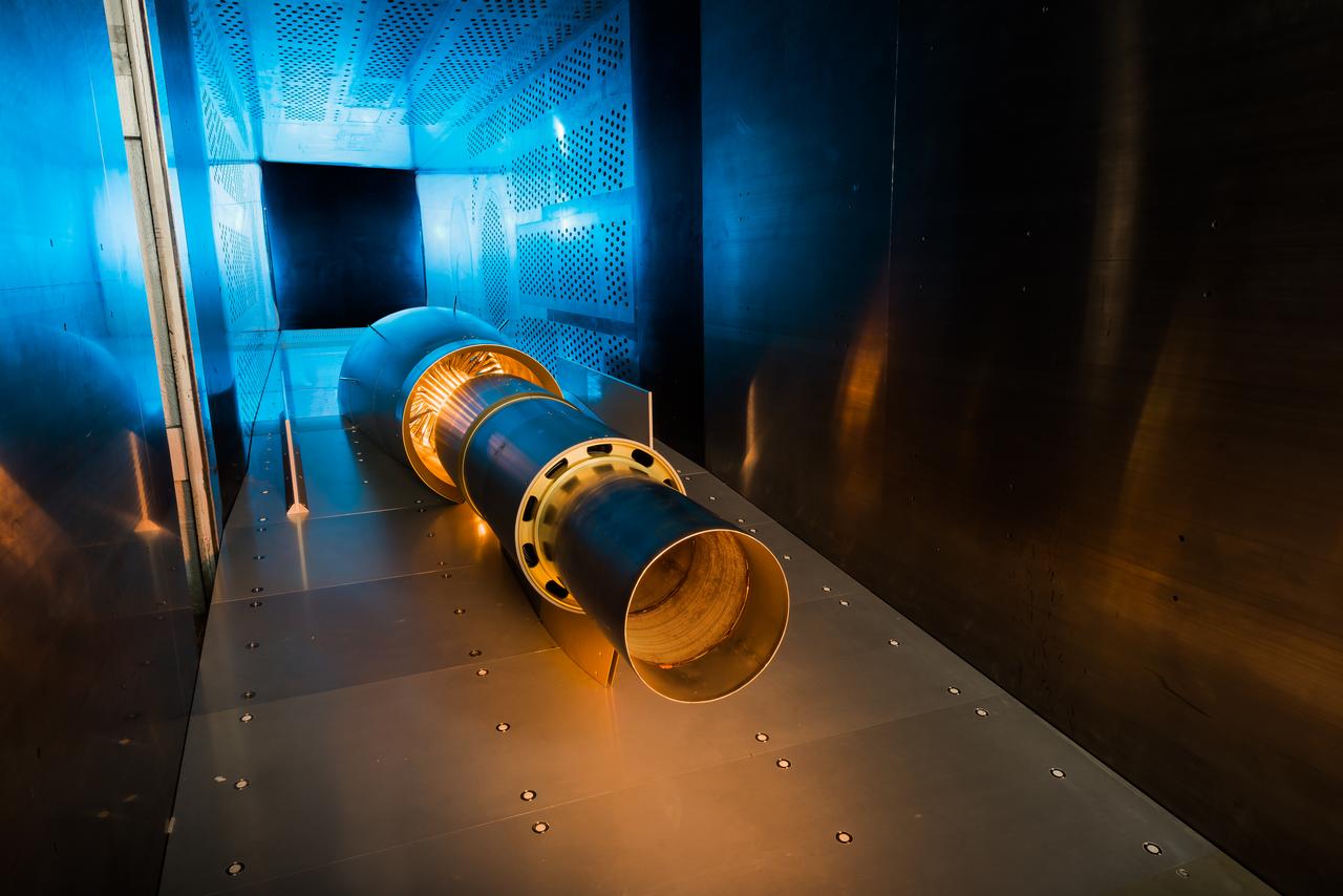
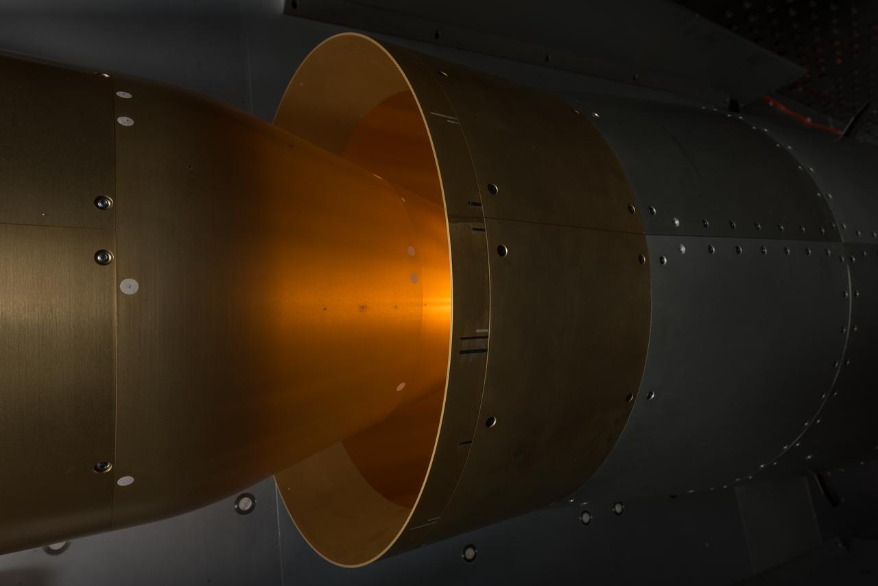
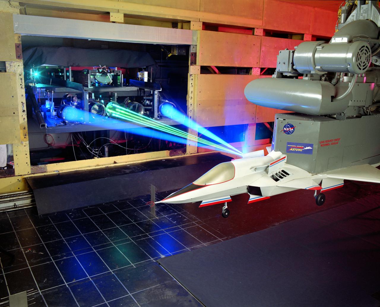
A spectrally resolved Rayleigh/Mie scattering diagnostic was developed to measure temperature and wingspan wise velocity in the vicinity of an ASTOVL aircraft model tested in the Lewis, now Glenn, 9x15 Low Speed Wind Tunnel. This was done for the Phase III hot gas ingestion study of ground-effect flow-field on such aircraft during hover or vertical landing.

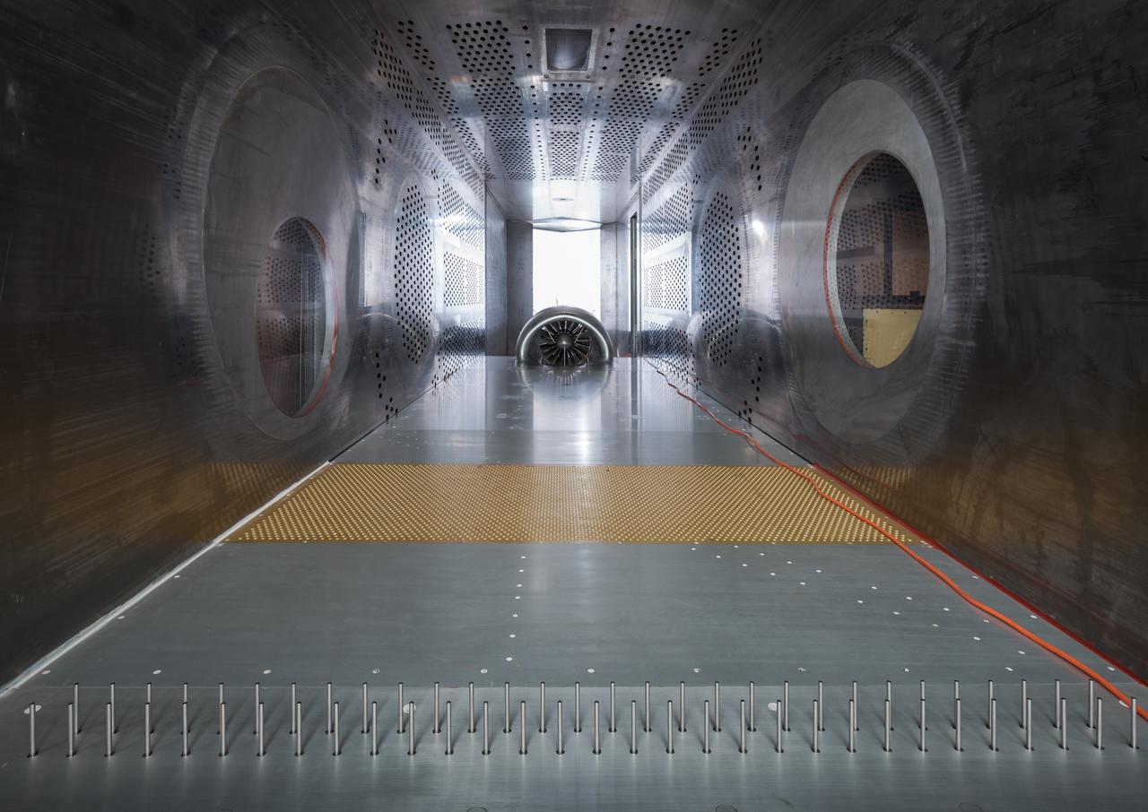
Raised Floor Calibration Hardware for the Boundary Layer Ingesting Inlet Distortion Tolerant Fan tests to be performed in the 8' x 6' Supersonic Wind Tunnel at NASA Glenn Research Center.
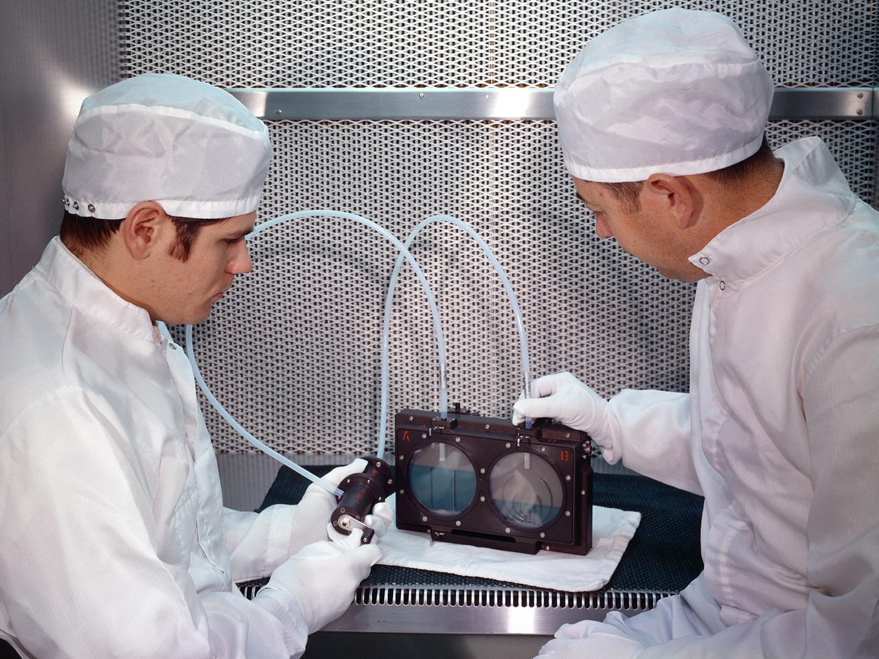
Two researchers at the National Aeronautics and Space Administration (NASA) Lewis Research Center demonstrate the test equipment they devised to study the transfer of liquid in microgravity onboard the Apollo 14 mission. The test was an early step in developing the ability to transfer liquids from a tanker vehicle to spacecraft in space. Researchers needed to know the tank’s outflow characteristics, the fluid’s behavior when entering new tank, and the effects of accelerations. Others had performed some calculations and analytical studies, but no one had examined the complete transfer from one tank to another in microgravity. The early calculations concluded that the transfer process was impossible without devices to control the liquid and gas. This investigation specifically sought to demonstrate the effectiveness of two different surface-tension baffle designs. The experiment was an entirely closed system with two baffled-tanks. The researchers also built a similar device without the baffles. The experiment was carried onboard the Apollo 14 spacecraft and conducted during the coast period on the way to the moon. The two surface tension baffle designs in the separate tanks were shown to be effective both as supply tanks and as receiver tanks. The liquid transferred within two percent of the design value with ingesting gas. The unbaffled tanks ingested gas after only 12-percent of the fluid had transferred.
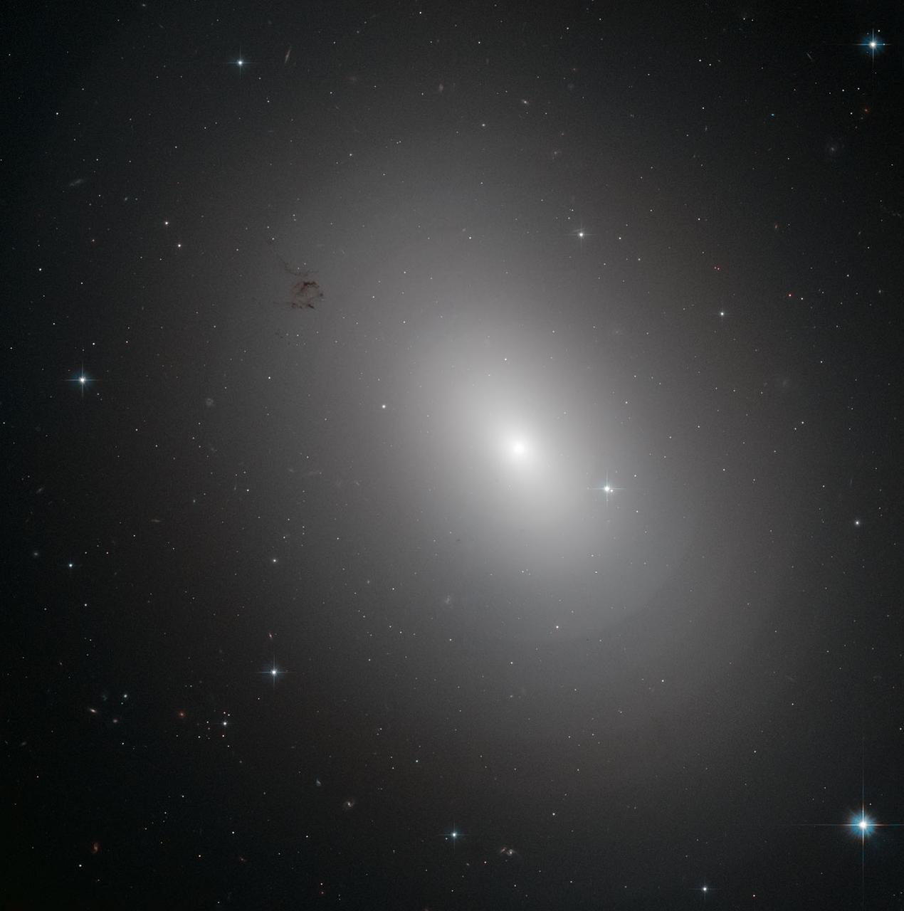
The glowing object in this Hubble Space Telescope image is an elliptical galaxy called NGC 3923. It is located over 90 million light-years away in the constellation of Hydra. NGC 3923 is an example of a shell galaxy where the stars in its halo are arranged in layers. Finding concentric shells of stars enclosing a galaxy is quite common and is observed in many elliptical galaxies. In fact, every tenth elliptical galaxy exhibits this onion-like structure, which has never been observed in spiral galaxies. The shell-like structures are thought to develop as a consequence of galactic cannibalism, when a larger galaxy ingests a smaller companion. As the two centers approach, they initially oscillate about a common center, and this oscillation ripples outwards forming the shells of stars just as ripples on a pond spread when the surface is disturbed. NGC 3923 has over twenty shells, with only a few of the outer ones visible in this image, and its shells are much more subtle than those of other shell galaxies. The shells of this galaxy are also interestingly symmetrical, while other shell galaxies are more skewed. Credit: ESA/Hubble & NASA
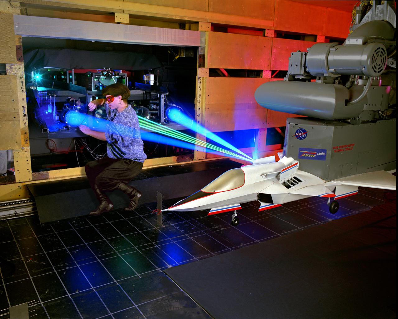
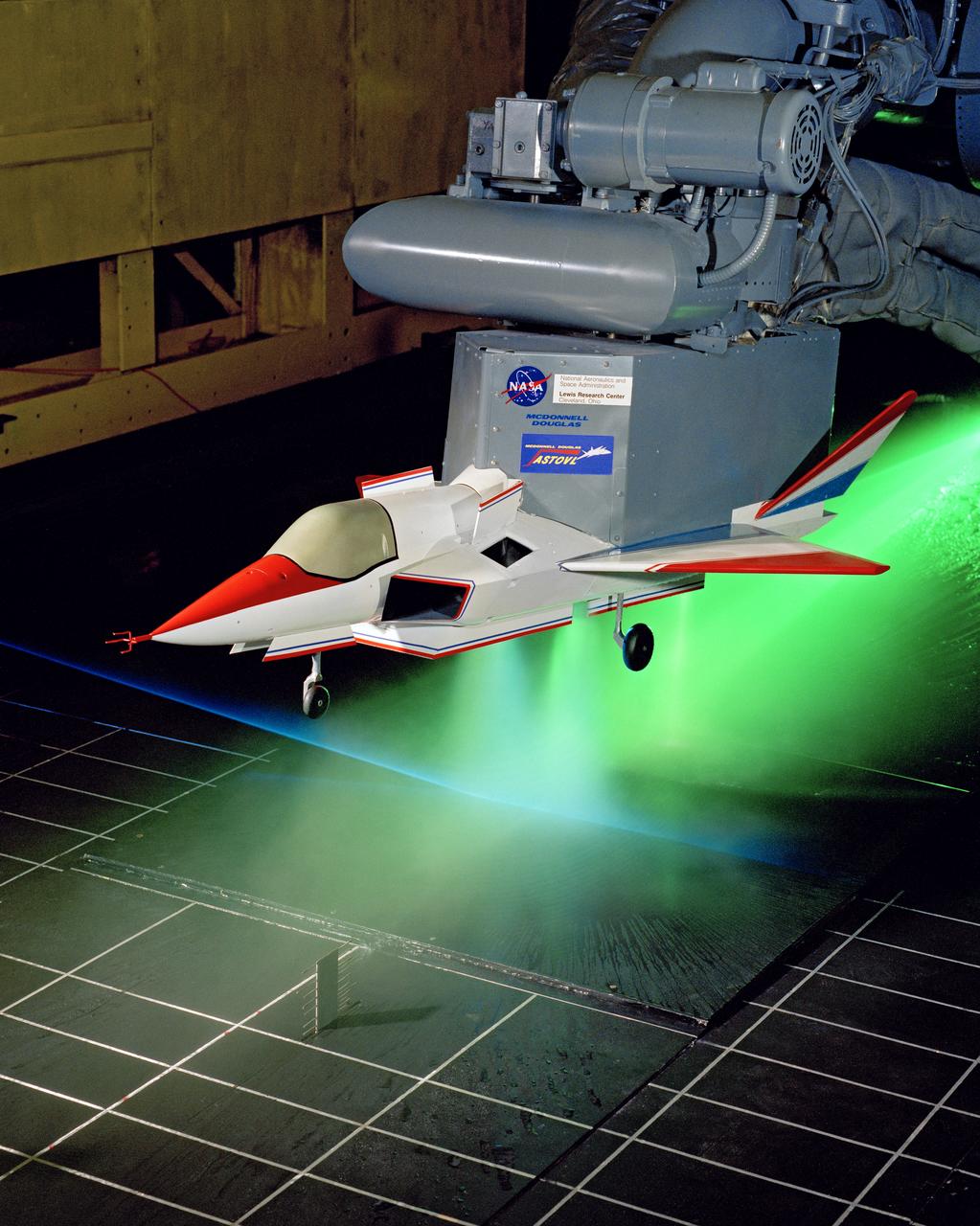
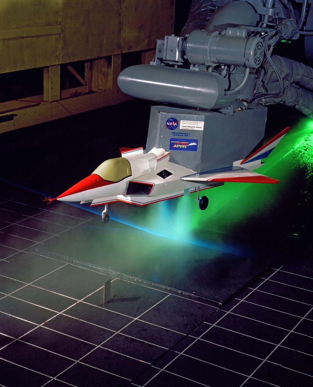
The 9x15 low speed tunnel tests take off and landing of aircraft. The laser velocimetry system for flow measurement show here, with the color blue and green lasers, measures engine exhaust that comes back up from the ground. The STOVL model n the 9x15 low speed wind tunnel, building 39, is similar to the British Harrier aircraft.
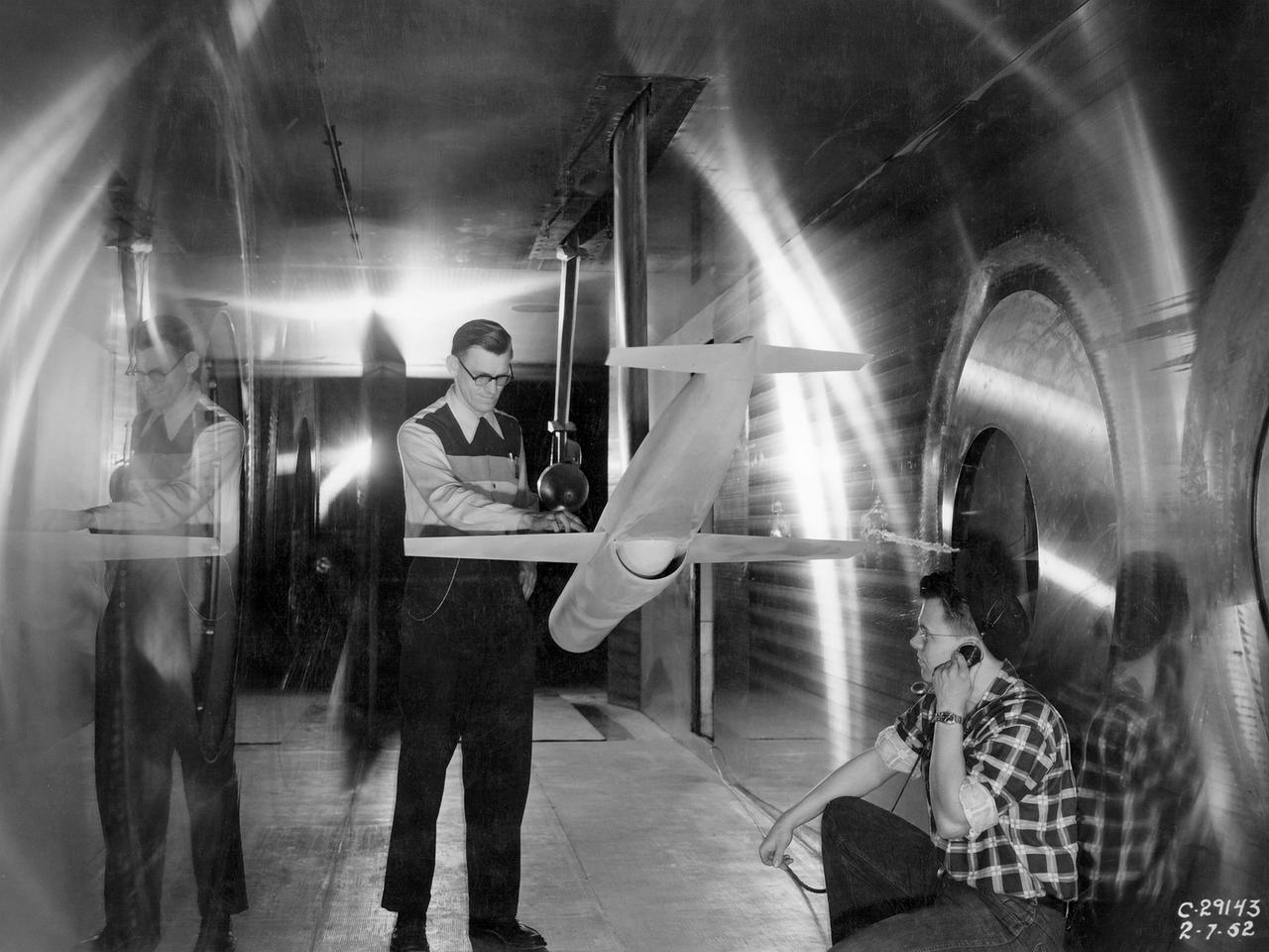
The National Advisory Committee for Aeronautics (NACA) Aircraft Engine Research Laboratory acquired two Lockheed P–38J Lightning in October 1944 to augment their burgeoning icing research program. The P–38 was a high-altitude interceptor with a unique twin fuselage configuration. Lockheed designed the aircraft in 1938 and 1939. Its two Allison V–1710 engines carried the aircraft to altitudes up to 40,000 feet. The P–38 was used extensively during World War II in a variety of roles. In August 1943, Lockheed began producing an improved version, the P–38J that included better cockpit heating, engine cooling, and dive flaps. The military loaned the NACA two P–38Js to determine the amount of ice formation on the induction system of the turbosupercharger-equipped engines. In 1944 and 1945 one of the aircraft was subjected to ground tests using an engine blower on the hangar apron. The V–1710 was run over a full range of speeds as different levels of water were injected into the blower and sprayed onto the engine. The other P–38J was flown at 10,000 feet altitude with water sprayed into the engine to simulate rain. The tests confirmed that closing the intercooler flap added protection against the ice by blocking water ingestion and increasing engine heat. NACA pilot Joseph Walker joined the Cleveland laboratory in early 1945 as a physicist. Walker had flown P–38s during World, and later claimed that seeing the NACA’s two P–38Js inspired him to return to his earlier calling as a pilot, this time with the NACA. Walker was particularly active in the icing flight program during his five years of flying in Cleveland.
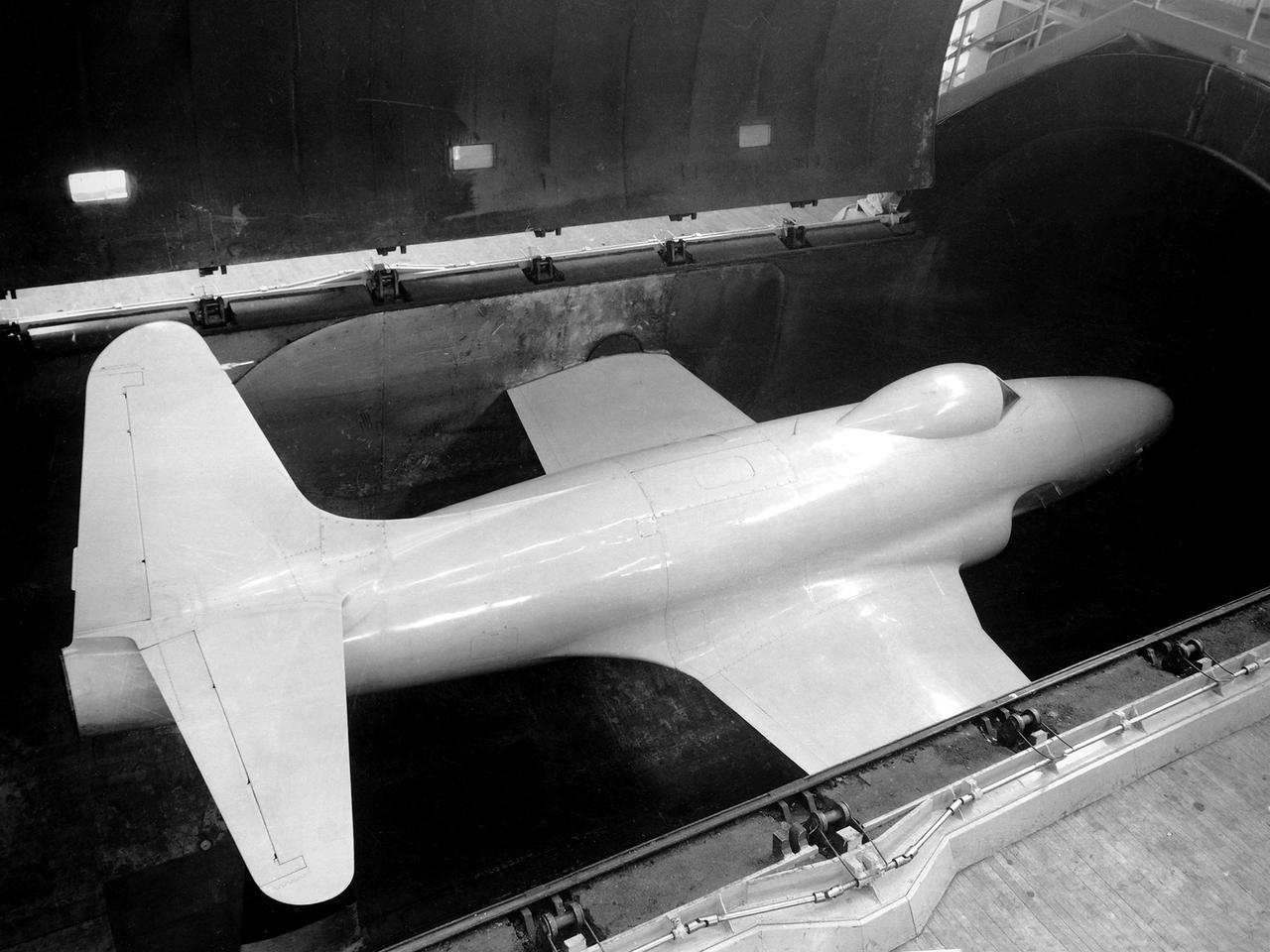
A researcher at the National Advisory Committee for Aeronautics (NACA) Lewis Flight Propulsion Laboratory checks the setup of a RJM-2 ramjet model in the test section of the 8- by 6-Foot Supersonic Wind Tunnel. The 8- by 6 was not only the laboratory’s first large supersonic wind tunnel, but it was also the NACA’s first facility capable of testing an operating engine at supersonic speeds. The 8- by 6-foot tunnel has been used to study engine inlets, fuel injectors, flameholders, exit nozzles, and controls on ramjet and turbojet propulsion systems. The 8-foot wide and 6-foot tall test section consisted of 1-inch thick steel plates with hatches on the floor and ceiling to facilitate the installation of the test article. The two windows seen on the right wall allowed photographic equipment to be set up. The test section was modified in 1956 to accommodate transonic research. NACA engineers drilled 4,700 holes into the test section walls to reduce transonic pressure disturbances and shock waves. NACA Lewis undertook an extensive research program on ramjets in the 1940s using several of its facilities. Ramjets provide a very simple source of propulsion. They are basically a tube which ingests high speed air, ignites it, and then expels the heated air at a significantly higher velocity. Ramjets are extremely efficient and powerful but can only operate at high speeds. Therefore, they require a booster rocket or aircraft drop to accelerate them to high speeds before they can operate.

National Aeronautics and Space Administration (NASA) researcher John Carpenter inspects an aircraft model with a four-fan thrust reverser which would be studied in the 9- by 15-Foot Low Speed Wind Tunnel at the Lewis Research Center. Thrust reversers were introduced in the 1950s as a means for slowing high-speed jet aircraft during landing. Engineers sought to apply the technology to Vertical and Short Takeoff and Landing (VSTOL) aircraft in the 1970s. The new designs would have to take into account shorter landing areas, noise levels, and decreased thrust levels. A balance was needed between the thrust reverser’s efficiency, its noise generation, and the engine’s power setting. This model underwent a series of four tests in the 9- by 15-foot tunnel during April and May 1974. The model, with a high-wing configuration and no tail, was equipped with four thrust-reverser engines. The investigations included static internal aerodynamic tests on a single fan/reverser, wind tunnel isolated fan/reverser thrust tests, installation effects on a four-fan airplane model in a wind tunnel, and single reverser acoustic tests. The 9-by 15 was built inside the return leg of the 8- by 6-Foot Supersonic Wind Tunnel in 1968. The facility generates airspeeds from 0 to 175 miles per hour to evaluate the aerodynamic performance and acoustic characteristics of nozzles, inlets, and propellers, and investigate hot gas re-ingestion of advanced VSTOL concepts. John Carpenter was a technician in the Wind Tunnels Service Section of the Test Installations Division.
The 9x15 low speed tunnel tests take off and landing of aircraft. The laser velocimetry system for flow measurement show here, with the color blue and green lasers, measures engine exhaust that comes back up from the ground. The STOVL model n the 9x15 low speed wind tunnel, building 39, is similar to the British Harrier aircraft.