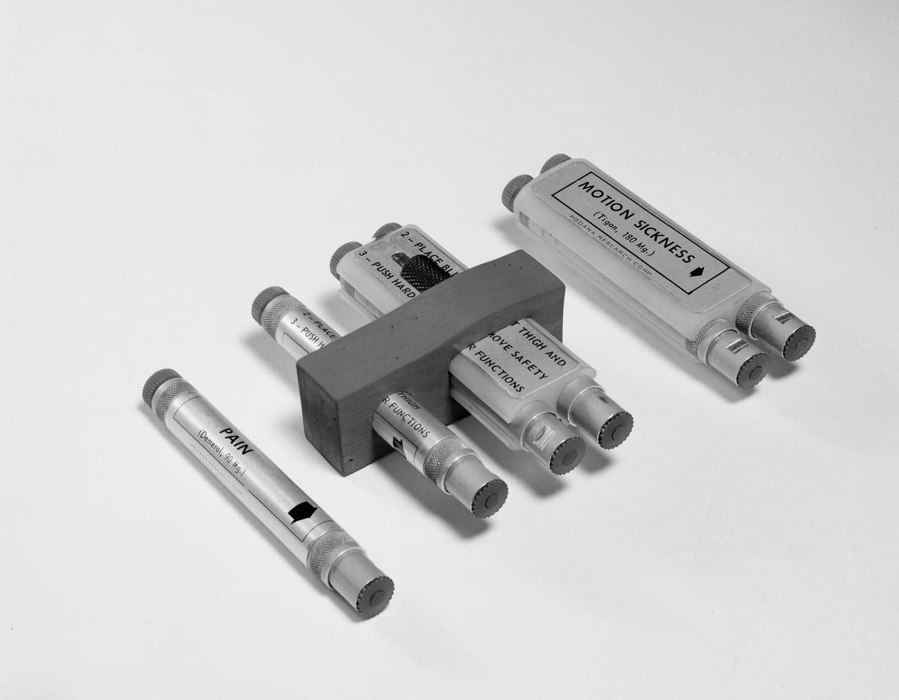
S62-08371 (1962) --- The automatic medical injectors carried on the Mercury-Atlas 9 flight. The injectors provide the astronaut with injection tubes of Tigan, for preventing motion sickness and Demerol, for relieving pain. The tubes encased in the block are stowed in the astronauts survival kit. The single injection tubes are placed in a pocket of the astronauts spacesuit. Photo credit: NASA
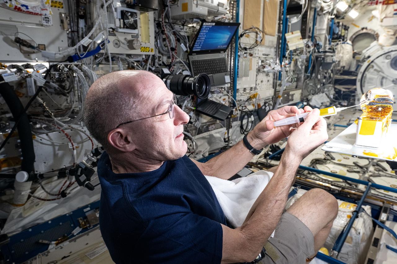
iss072e742488 (March 2, 2025) --- NASA astronaut and Expedition 72 Flight Engineer Don Pettit injects yellow ink into a ball of water shaped by microgravity and attached to research hardware by surface tension. Pettit was demonstrating simple space physics phenomena inside the International Space Station's Kibo laboratory module.

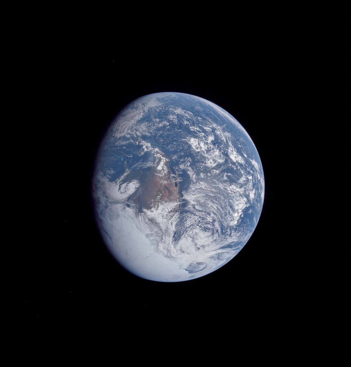
AS16-118-18873 (16 April 1972) --- A good view of Earth photographed shortly after trans-lunar injection of April 16, 1972. Although there is much cloud cover (over Canada and the oceans), the United States in large part, most of Mexico and some parts of Central America are clearly visible. Note Lake Michigan and Lake Superior, also note the Bahama Banks at upper right part of the sphere. A large part of the Rocky Mountain Range is also visible. Just beginning man's fifth lunar landing mission were astronauts John W. Young, commander; Thomas K. Mattingly II, command module pilot; and Charles M. Duke Jr., lunar module pilot. While astronauts Young and Duke descended in the Lunar Module (LM) to explore the moon, astronaut Mattingly remained with the Command and Service Modules (CSM) in lunar orbit.
AS16-118-18885 (16 April 1972) --- A good view of Earth photographed about one and one-half hours after trans-lunar injection on April 16, 1972. Although there is much cloud cover, the United States in large part, most of Mexico and some parts of Central America are clearly visible. Note Lake Michigan and Lake Superior and the Bahama Banks (see different shade of blue below Florida). Just beginning man's fifth lunar landing mission were astronauts John W. Young, commander; Thomas K. Mattingly, II, command module pilot and Charles M. Duke Jr., lunar module pilot. While astronauts Young and Duke descended in the Lunar Module (LM) "Orion" to explore the Descartes highlands region of the moon, astronaut Mattingly remained with the Command and Service Modules (CSM) "Casper" in lunar orbit.
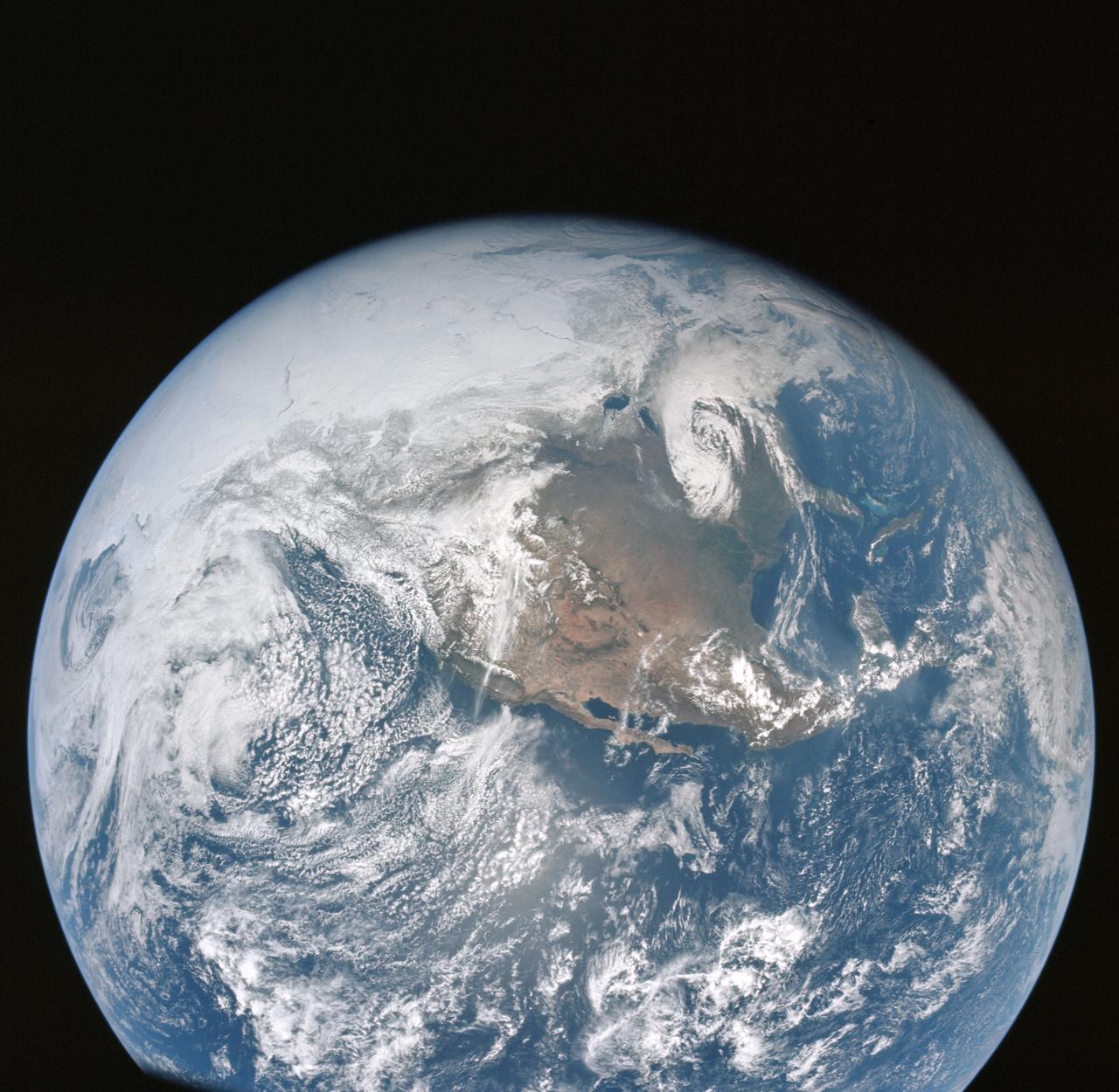
AS16-118-18880 (16 April 1972) --- A good view of Earth photographed about one hour after trans-lunar injection on April 16, 1972. Although there is much cloud cover, the United States in large part, most of Mexico and some of Central America are clearly visible. Note the Great Lakes (Michigan and Superior) and the Bahama Banks (note different shade of blue below Florida). While astronauts John W. Young, commander, and Charles M. Duke Jr., lunar module pilot, descended in the Lunar Module (LM) "Orion" to explore the Descartes highlands region of the moon, astronaut Thomas K. (Ken) Mattingly II, command module pilot, remained with the Command and Service Modules (CSM) "Casper" in lunar orbit.

Light material emplaced within darker vein material is seen in this view of a mineral vein at the "Garden City" site on lower Mount Sharp, Mars. The Mars Hand Lens Imager (MAHLI) on the arm of NASA's Curiosity Mars Rover took the image on April 4, 2015, during the 946th Martian day, or sol, of Curiosity's work on Mars. The area shown is roughly 0.4 inch (1 centimeter) wide. Differences in textures of light-toned veins in the Garden City complex of crisscrossing mineral veins are clues that these veins may result from distinct fluid events. This example shows where injection of light material into a prior dark vein suggests high fluid pressure. Differences in textures of light-toned veins in the Garden City complex of crisscrossing mineral veins are clues that these veins may result from distinct fluid events. This vein's texture shows indications of crystal growth, suggesting that crystallization may have exerted a force for opening the fracture filled by the vein. Different examples are at PIA19925 and PIA19927. Mineral veins often form where fluids move through fractured rocks, depositing minerals in the fractures and affecting chemistry of the surrounding rock. At Garden City, the veins have been more resistant to erosion than the surrounding host rock. The fluid movement through fractures at Garden City occurred later than wet environmental conditions in which the host rock formed, before it hardened and cracked. Malin Space Science Systems, San Diego, built and operates MAHLI. NASA's Jet Propulsion Laboratory, a division of the California Institute of Technology in Pasadena, manages the Mars Science Laboratory Project for the NASA Science Mission Directorate, Washington. JPL designed and built the project's Curiosity rover. http://photojournal.jpl.nasa.gov/catalog/PIA19926

LEAN DIRECT INJECTION FUEL INJECTOR
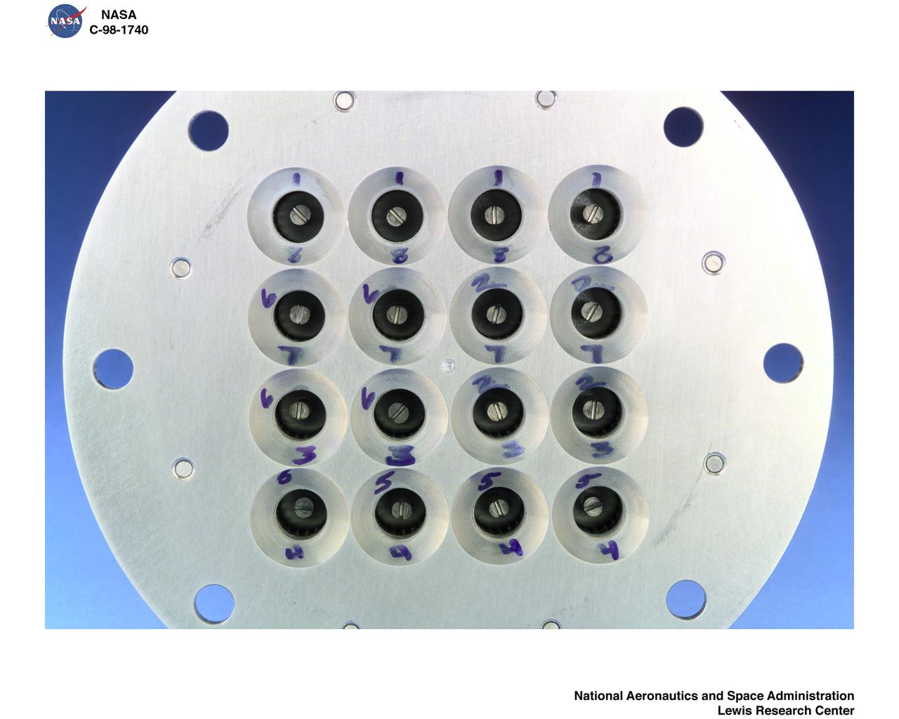
LEAN DIRECT INJECTION FUEL INJECTOR
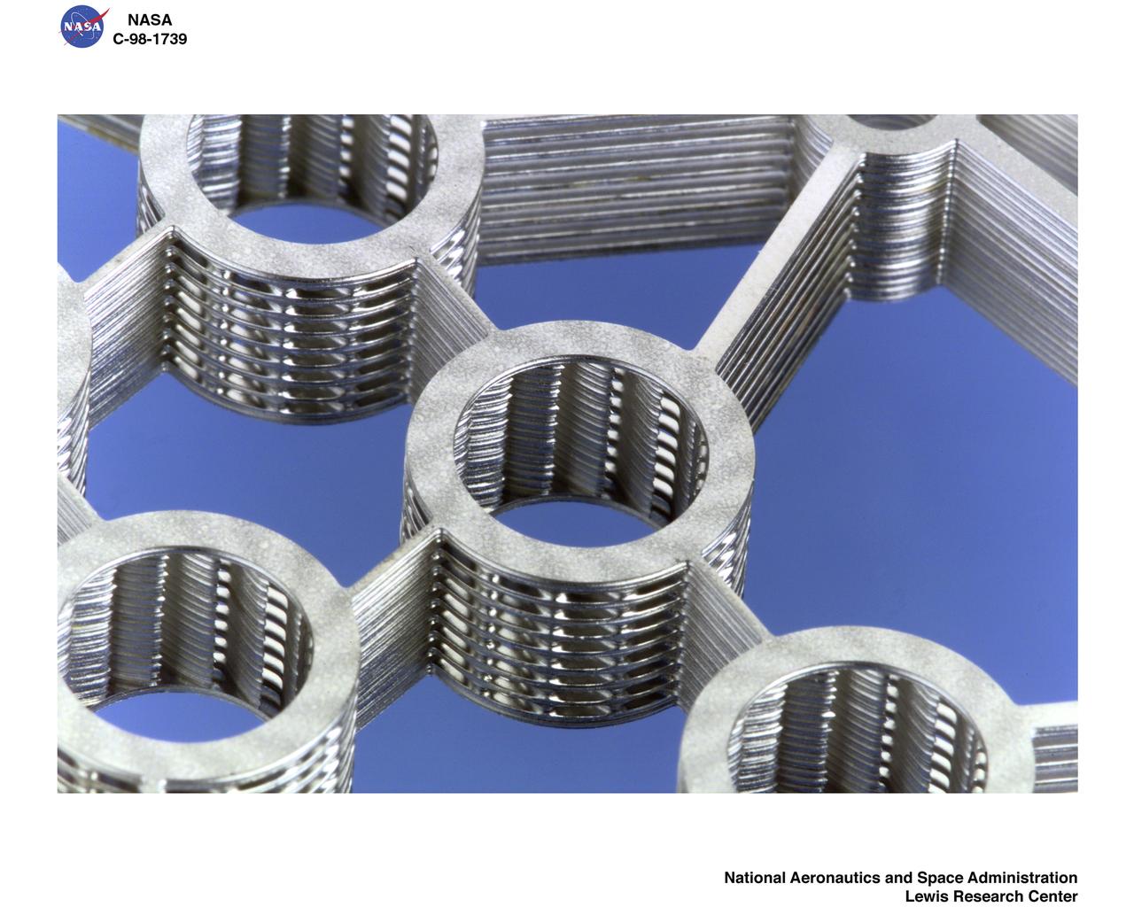
LEAN DIRECT INJECTION FUEL INJECTOR
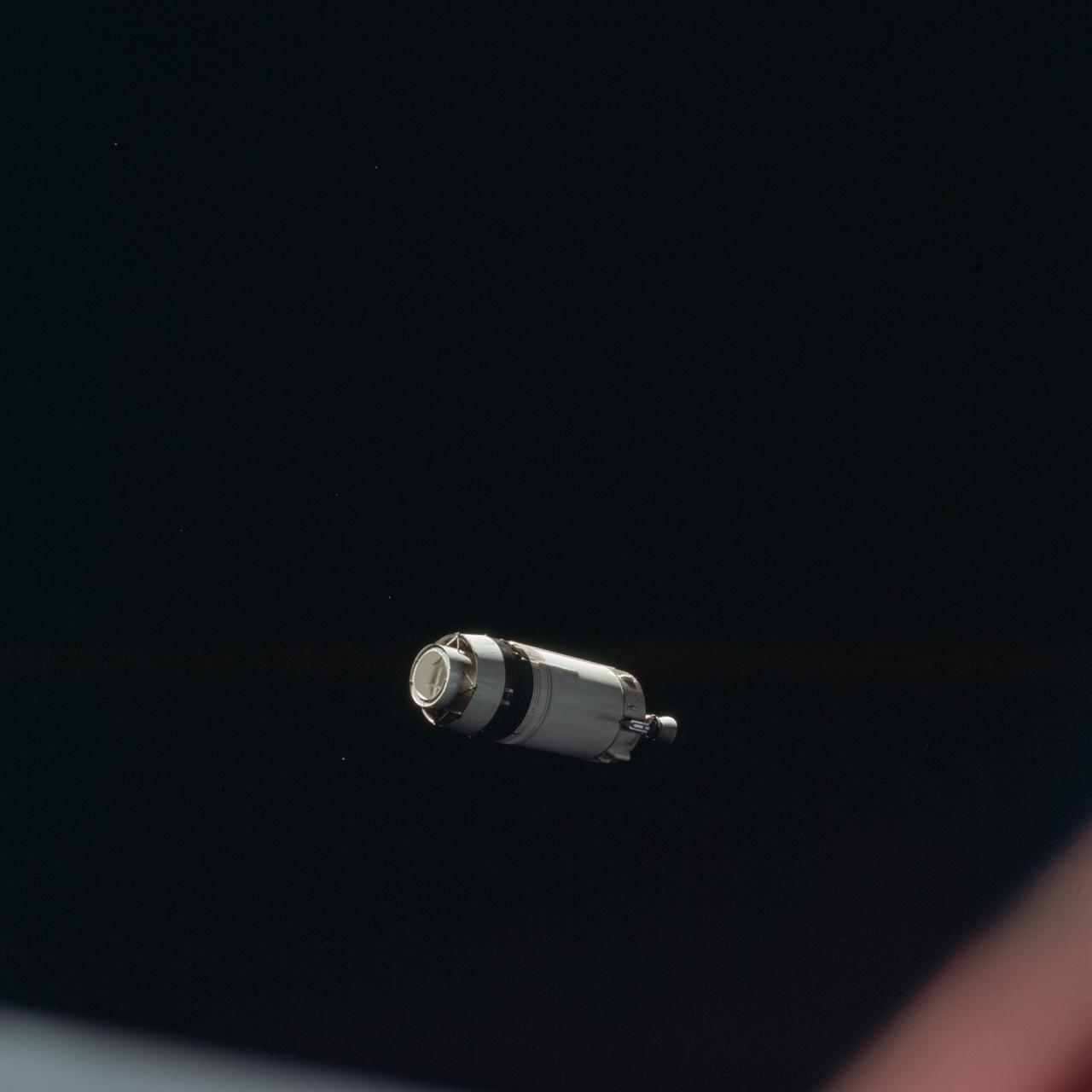
AS08-16-2584 (21 Dec. 1968) --- This is a photograph taken from the Apollo 8 spacecraft looking back at the Saturn V third (S-IVB) stage from which the spacecraft had just separated following trans-lunar injection. Attached to the S-IVB is the Lunar Module Test Article (LTA) which simulated the mass of a Lunar Module (LM) on the Apollo 8 lunar orbit mission. The 29-feet panels of the Spacecraft LM Adapter which enclosed the LTA during launch have already been jettisoned and are out of view. Sunlight reflected from small particles shows the "firefly" phenomenon which was reported by astronaut John H. Glenn Jr. during the first Earth-orbital flight, Mercury-Atlas 6 (MA-6) of the Mercury Program.
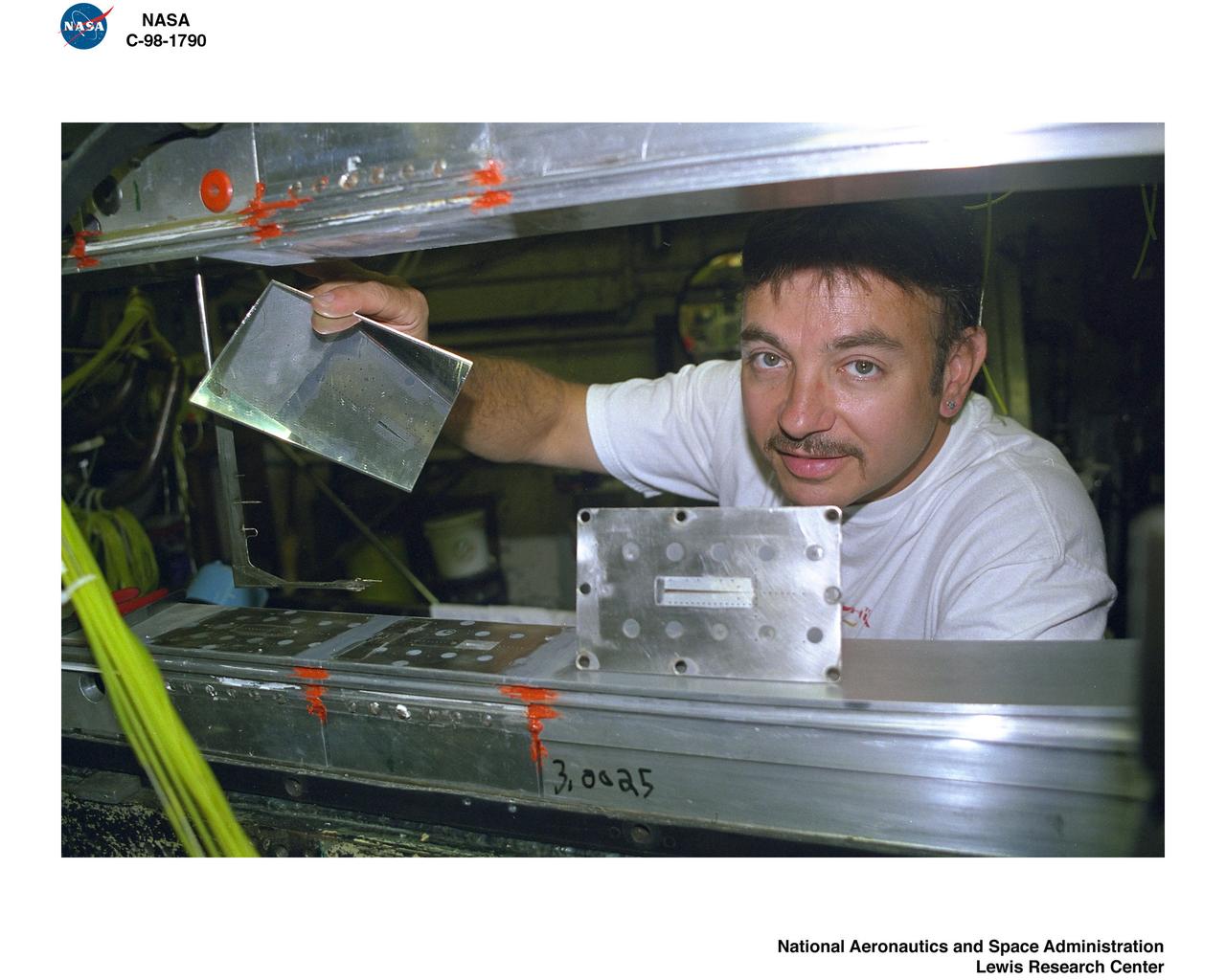
REASSEMBLY OF DUCT LAB SWT MACH 4-5 NOZZLE WITH MACH 2.0 INJECTION
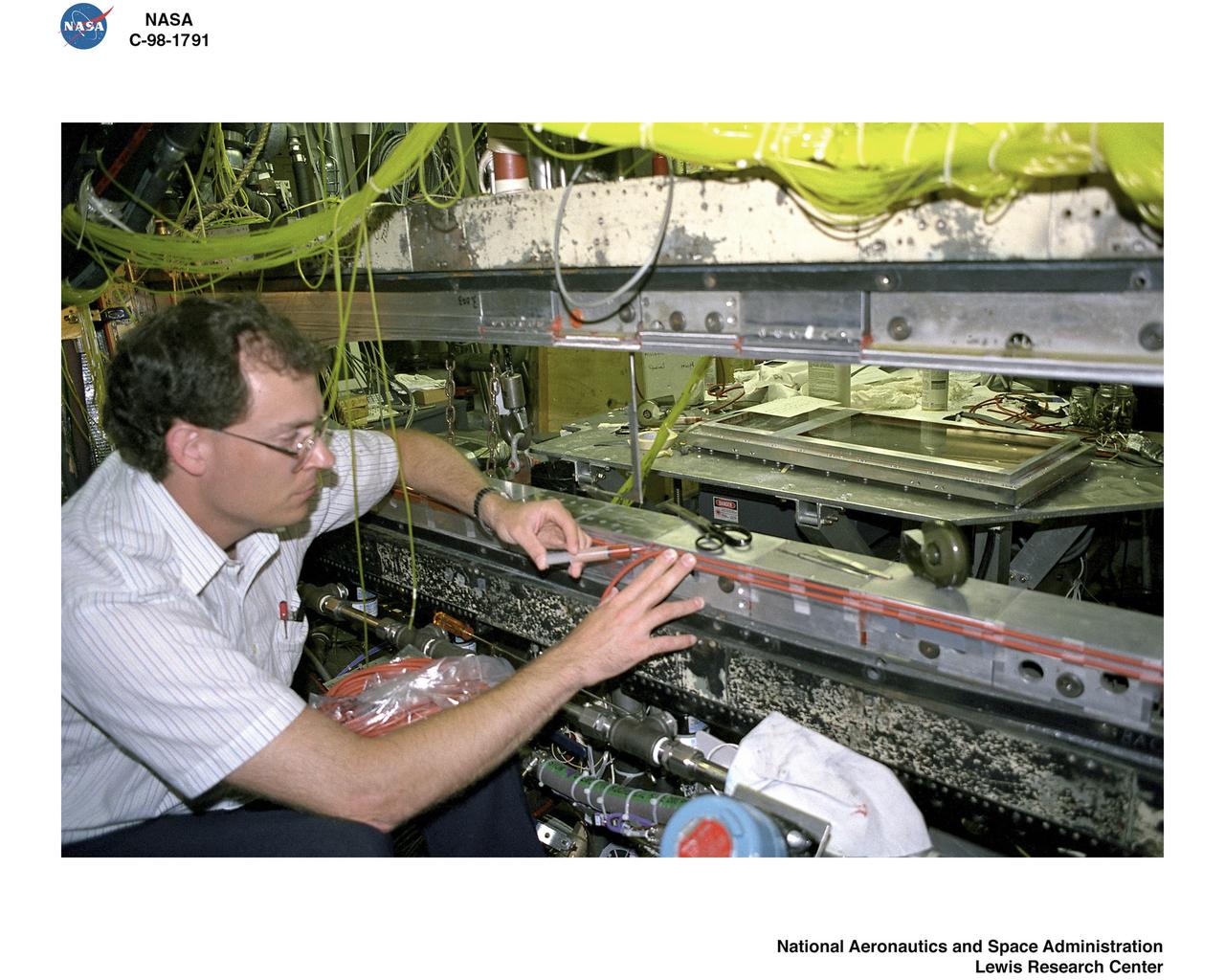
REASSEMBLY OF DUCT LAB SWT MACH 4-5 NOZZLE WITH MACH 2.0 INJECTION
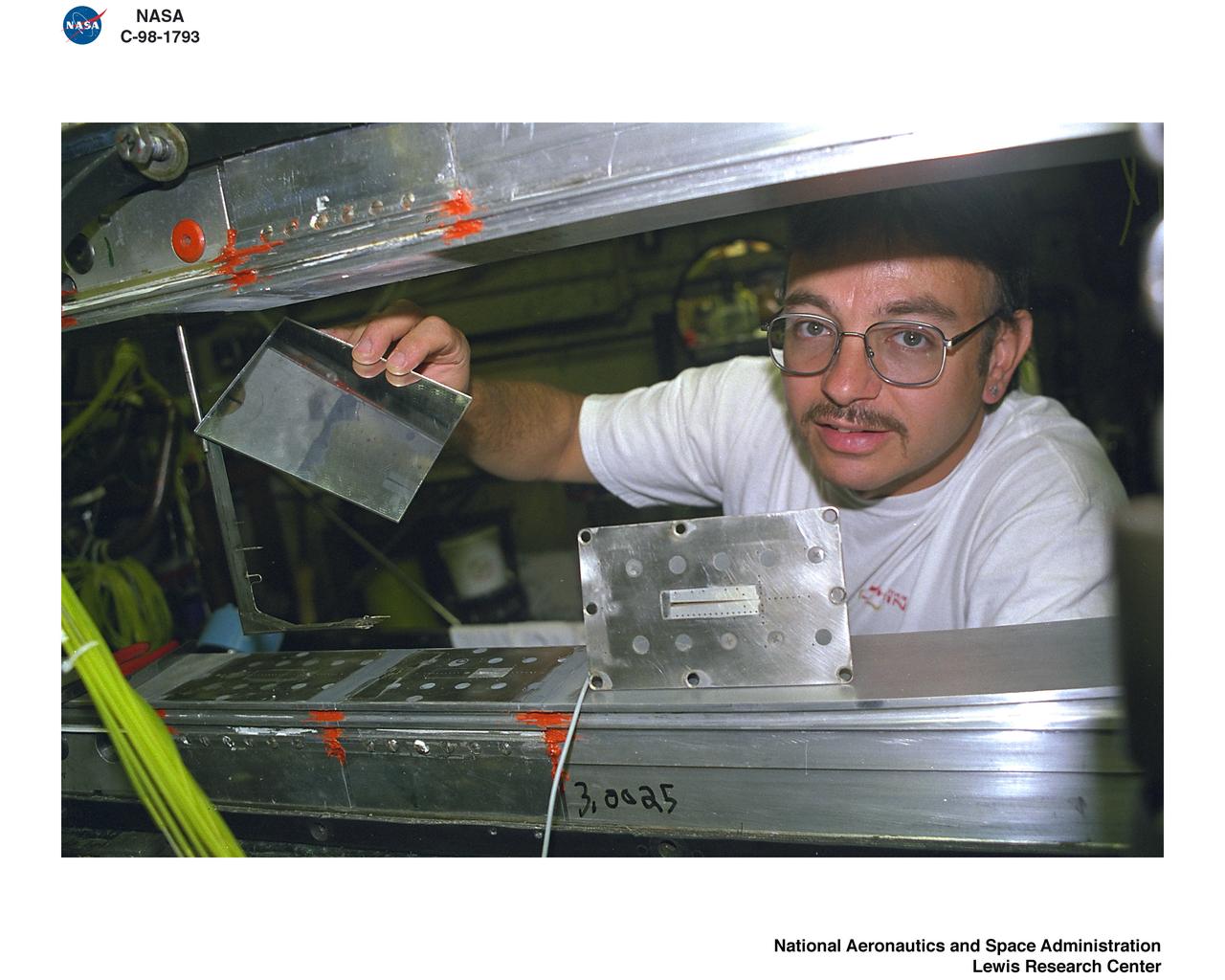
REASSEMBLY OF DUCT LAB SWT MACH 4-5 NOZZLE WITH MACH 2.0 INJECTION
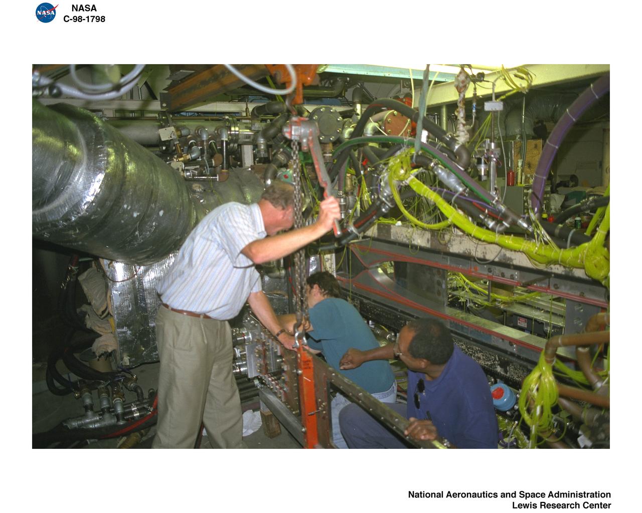
REASSEMBLY OF DUCT LAB SWT MACH 4-5 NOZZLE WITH MACH 2.0 INJECTION
Crew member practices injecting seed crystals into hand-held Protein Crystallization Apparatus for Microgravity (PCAM).
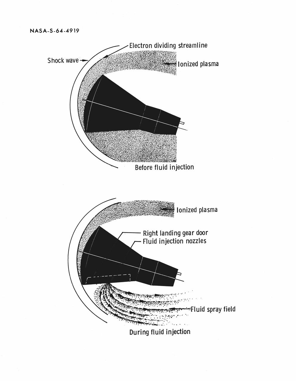
S64-04919 (September 1964) --- Diagram of reduction of the re-entry ionized plasma about a Gemini spacecraft by fluid injection, an experiment planned for the Gemini-Titan 3 orbital flight.
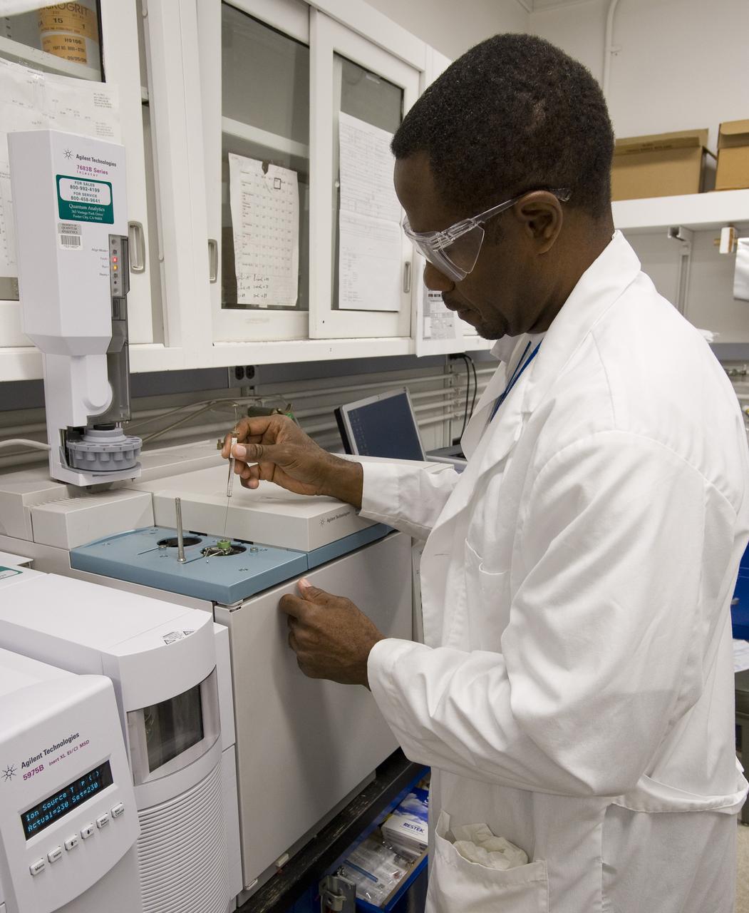
Dr George Cooper analyzes metoritic material by injecting samples into gas chromatograph-mass spectrometer. This instrument separates very complicated molecular mixtures into individual componds that are more easily identified.
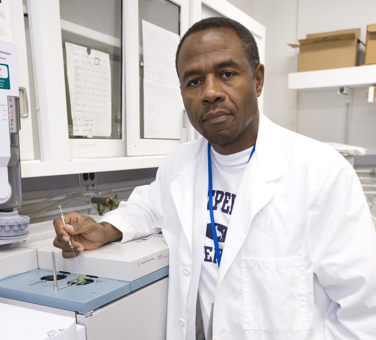
Dr George Cooper analyzes metoritic material by injecting samples into gas chromatograph-mass spectrometer. This instrument separates very complicated molecular mixtures into individual componds that are more easily identified.
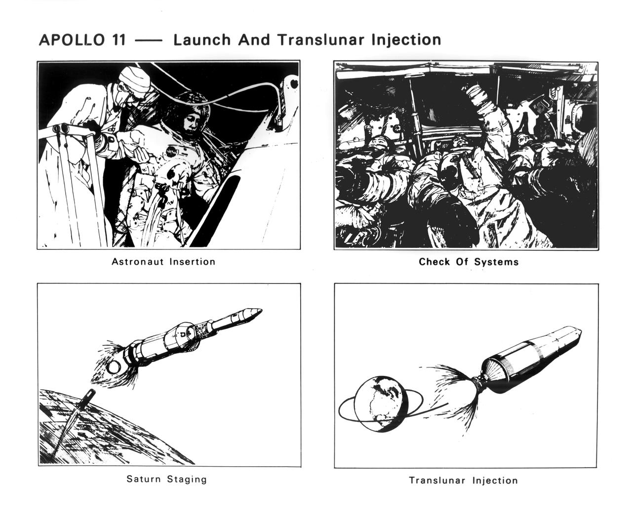
The Apollo 11 mission launched from the Kennedy Space Center (KSC) in Florida via the Marshall Space Flight Center (MSFC) developed Saturn V launch vehicle on July 16, 1969 and safely returned to Earth on July 24, 1969. Aboard the space craft were astronauts Neil A. Armstrong, commander; Michael Collins, Command Module (CM) pilot; and Edwin E. (Buzz) Aldrin Jr., Lunar Module (LM) pilot. With the success of Apollo 11, the national objective to land men on the Moon and return them safely to Earth had been accomplished. These sketches illustrate four of the early steps in the first manned lunar landing mission. The series begins with insertion of astronauts Neil Armstrong, Edwin Aldrin, and Michael Collins in the Apollo Command Module (CM). They checked out spacecraft systems and prepared for the launch. After two revolutions in Earth orbit, the Saturn V third stage reignited to place them into the translunar trajectory.
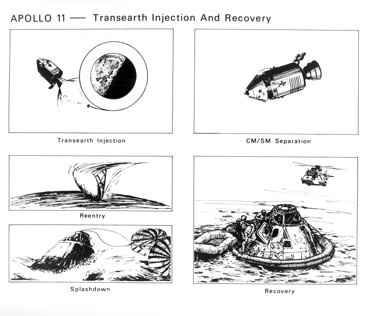
The Apollo 11 mission launched from the Kennedy Space Center (KSC) in Florida via the Marshall Space Flight Center (MSFC) developed Saturn V launch vehicle on July 16, 1969 and safely returned to Earth on July 24, 1969. Aboard the space craft were astronauts Neil A. Armstrong, commander; Michael Collins, Command Module (CM) pilot; and Edwin E. (Buzz) Aldrin Jr., Lunar Module (LM) pilot. With the success of Apollo 11, the national objective to land men on the Moon and return them safely to Earth had been accomplished. These sketches illustrate the steps taken by the astronauts to return to Earth. The service propulsion system engine was fired to increase space craft speed enough to escape Lunar orbit on a trajectory for Earth. Any necessary midcourse corrections were made enroute. Near the point of reentry into Earth’s atmosphere, the CM separated from the service module and turned 180 degrees so the heat shield faced forward on the line of flight. Friction of the atmosphere heated the shield to a white hot temperature, as a meteor, which slowed the craft as it reached lower altitudes. At about three miles altitude, drogue parachutes opened to stabilize the craft. Moments later the main parachutes opened to lower the CM to the waters of the Pacific Ocean. Helicopters and recovery crews from the U.S. S. Hornet aircraft carrier were standing by to pick up the astronauts.
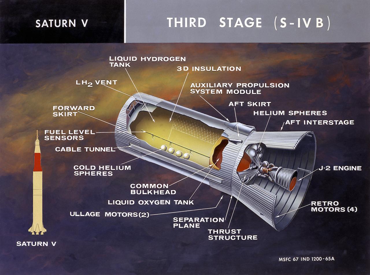
This cutaway illustration shows the Saturn V S-IVB (third) stage with the callouts of its major components. When the S-II (second) stage of the powerful Saturn V rocket burnt out and was separated the remaining units approached orbit around the Earth. Injection into the desired orbit was attaineded as the S-IVB (third stage) was ignited and burnt. The S-IVB stage was powered by a single 200,000-pound thrust J-2 engine and had a re-start capability built in for its J-2 engine. The S-IVB restarted to speed the Apollo spacecraft to escape velocity injecting it and the astronauts into a moon trajectory.
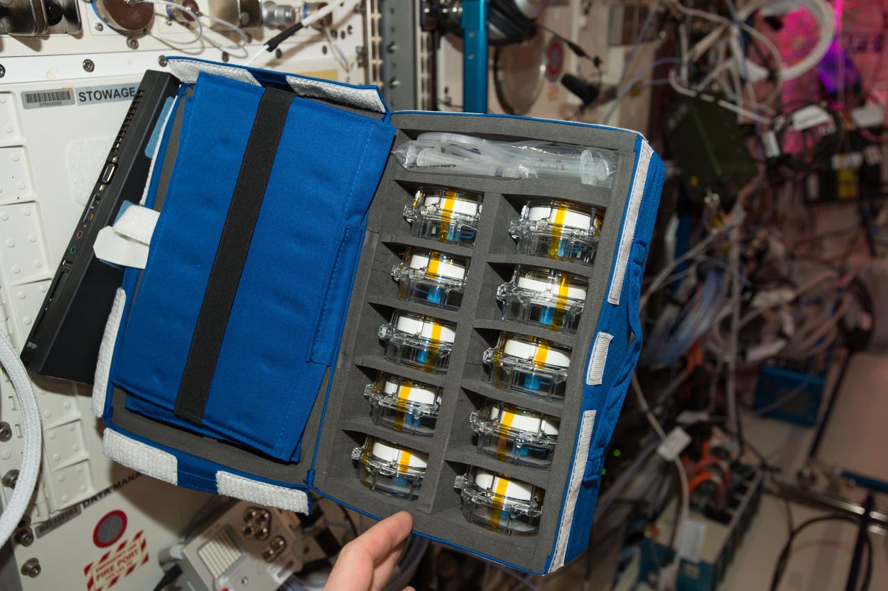
iss050e011332 (11/22/2016) --- A view of the Aquapad Sampling kit in a blue cargo transfer bag (CTB). Aquapad aims to improve the speed and efficiency of water potability tests onboard the ISS, by using a device that consists of a simple absorbent cotton, which is injected with 1 milliliter of water, and a tablet computer application,
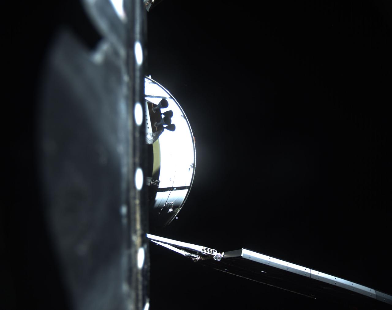
art001e001546 (Nov. 16, 2022) Approximately two hours after Artemis I launch on Nov. 16, 2022, the interim cryogenic propulsion stage separated from Orion after completing the translunar injection burn that put the spacecraft on course toward the Moon.
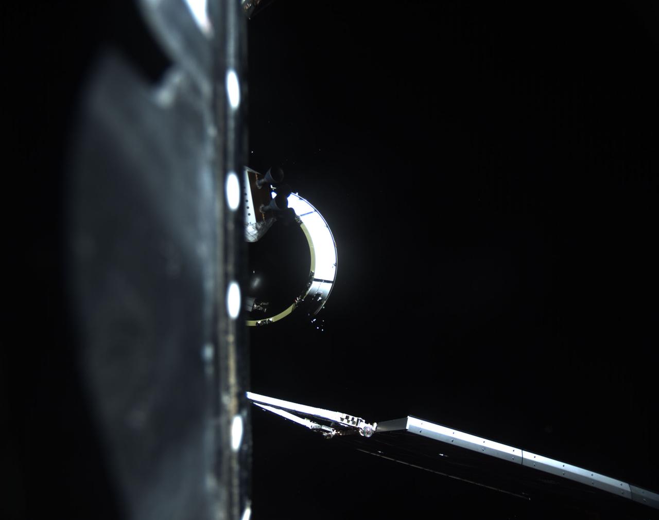
art001e001606 (Nov. 16, 2022) Approximately two hours after Artemis I launch on Nov. 16, 2022, the interim cryogenic propulsion stage separated from Orion after completing the translunar injection burn that put the spacecraft on course toward the Moon.
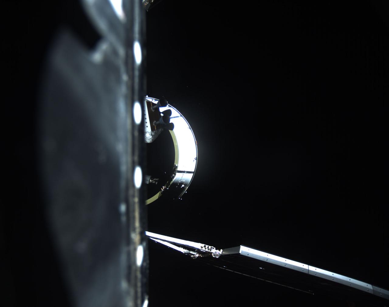
art001e001577 (Nov. 16, 2022) Approximately two hours after Artemis I launch on Nov. 16, 2022, the interim cryogenic propulsion stage separated from Orion after completing the translunar injection burn that put the spacecraft on course toward the Moon.
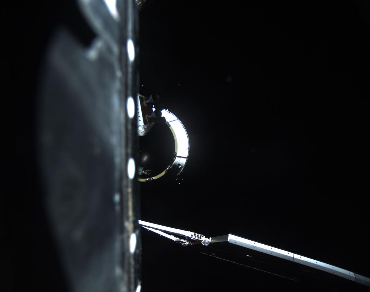
art001e001610 (Nov. 16, 2022) Approximately two hours after Artemis I launch on Nov. 16, 2022, the interim cryogenic propulsion stage separated from Orion after completing the translunar injection burn that put the spacecraft on course toward the Moon.
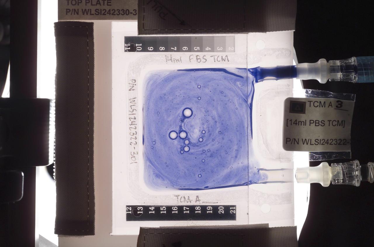
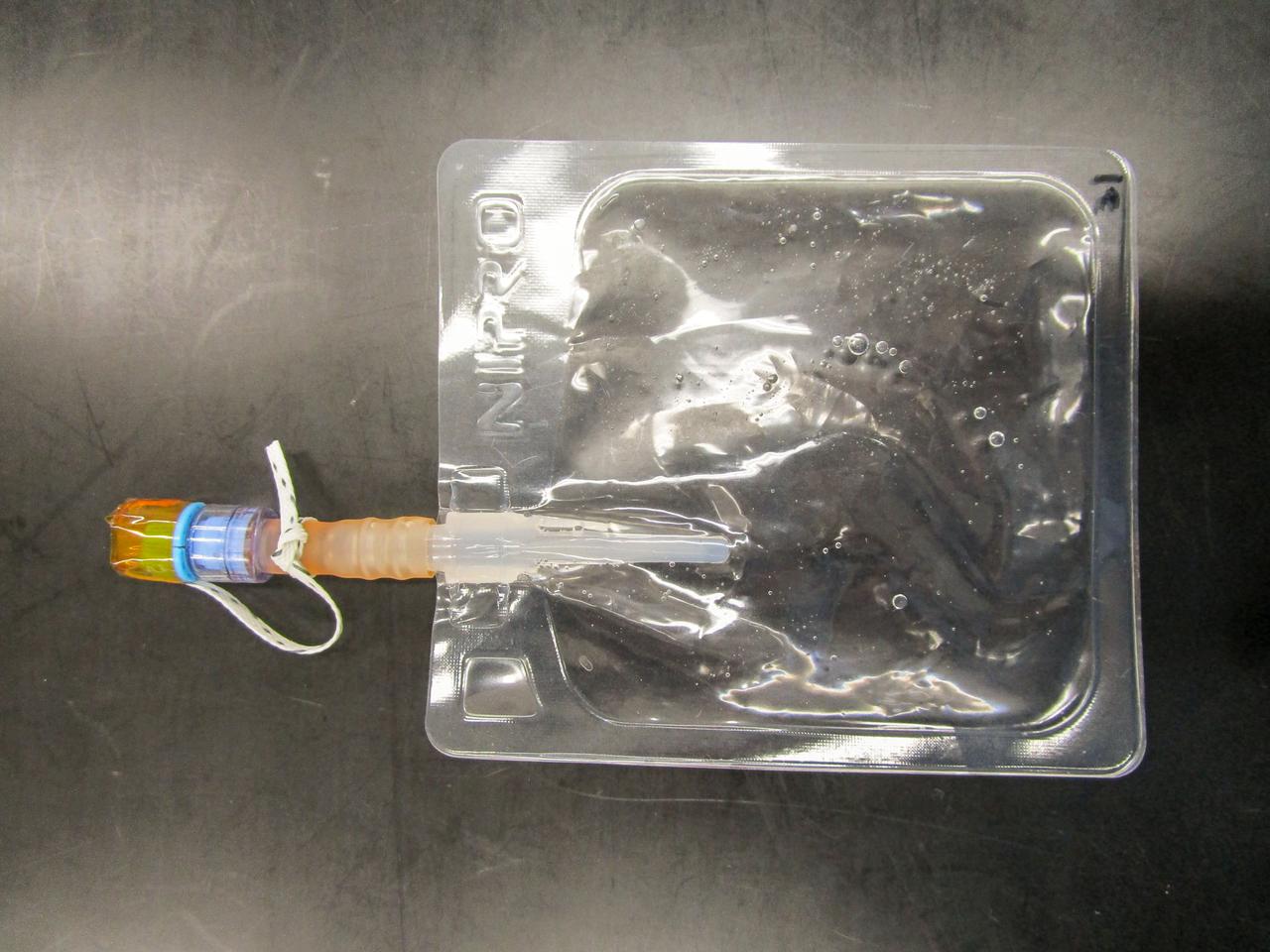
Aboard the International Space Station (ISS), the Tissue Culture Module (TCM) is the stationary bioreactor vessel in which cell cultures grow. However, for the Cellular Biotechnology Operations Support Systems-Fluid Dynamics Investigation (CBOSS-FDI), color polystyrene beads are used to measure the effectiveness of various mixing procedures. The beads are similar in size and density to human lymphoid cells. Uniform mixing is a crucial component of CBOSS experiments involving the immune response of human lymphoid cell suspensions. The goal is to develop procedures that are both convenient for the flight crew and are optimal in providing uniform and reproducible mixing of all components, including cells. The average bead density in a well mixed TCM will be uniform, with no bubbles, and it will be measured using the absorption of light. In this photograph, beads are trapped in the injection port, with bubbles forming shortly after injection.
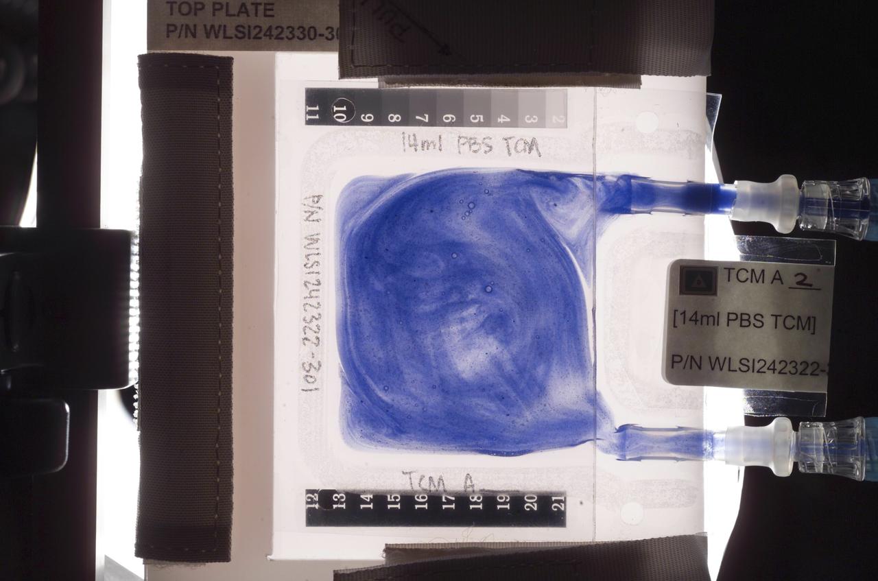
Aboard the International Space Station (ISS), the Tissue Culture Module (TCM) is the stationary bioreactor vessel in which cell cultures grow. However, for the Cellular Biotechnology Operations Support Systems-Fluid Dynamics Investigation (CBOSS-FDI), color polystyrene beads are used to measure the effectiveness of various mixing procedures. Uniform mixing is a crucial component of CBOSS experiments involving the immune response of human lymphoid cell suspensions. In this picture, the beads are trapped in the injection port shortly after injection. Swirls of beads indicate, event to the naked eye, the contents of the TCM are not fully mixed. The beads are similar in size and density to human lymphoid cells. The goal is to develop procedures that are both convenient for the flight crew and are optimal in providing uniform and reproducible mixing of all components, including cells. The average bead density in a well mixed TCM will be uniform, with no bubbles, and it will be measured using the absorption of light

This artist's concept depicts a scene from 4.5 billion years ago, when scientists believe giant impacts occurred on Mars, injecting debris deep into the planet's mantle. NASA's InSight lander detected this debris before the mission's end in 2022, and these findings from the mission were published in the journal Science on Aug. 28, 2025. The early solar system had many space rocks bashing into the young planets, and smaller impactors can be seen surrounding this giant one in the image. The giant asteroids or comets that sent debris into the Martian mantle would have released enough energy to melt continent-size swaths of the early crust and mantle into vast magma oceans. https://photojournal.jpl.nasa.gov/catalog/PIA26635
jsc2022e068258(5/11/2022) --- A preflight view of the Bag is used to culture nematodes in liquid medium, an injection port is available to transfer a portion of medium by using Syringe. Effect of the Space Environment on the Neural Integration System and Aging of the Model Animal C. elegans (Neural Integration System) uses nematodes to examine how microgravity affects the nervous system. Image courtesy of JAXA
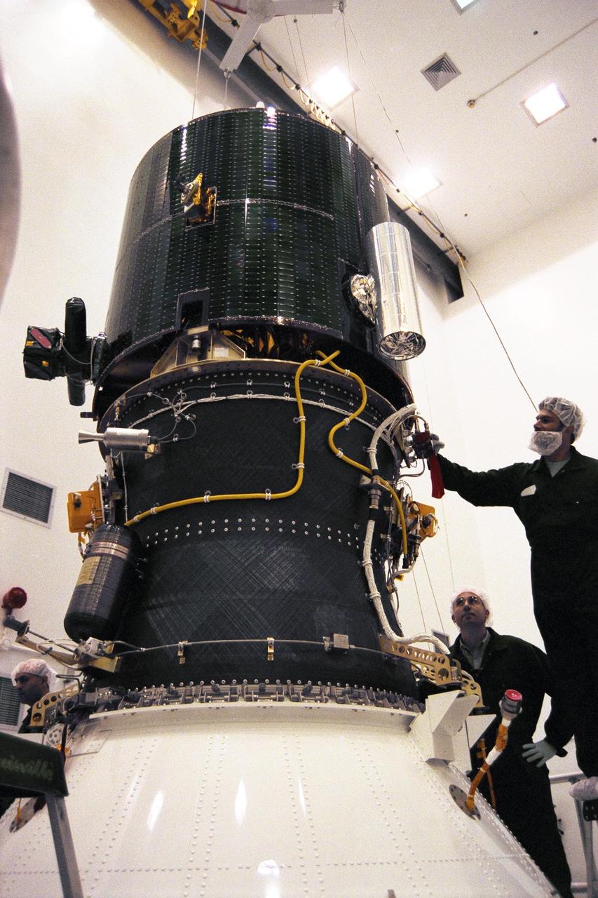
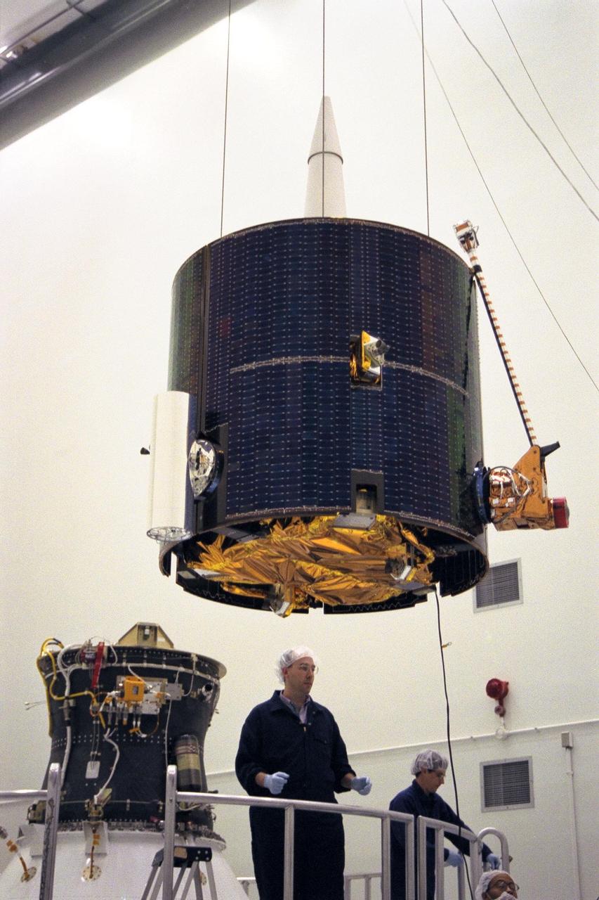
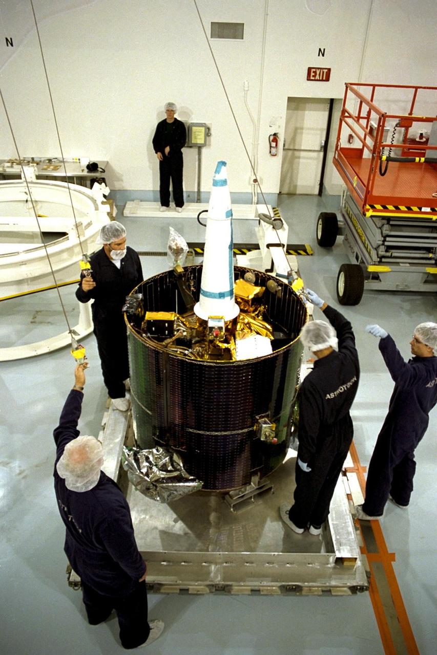
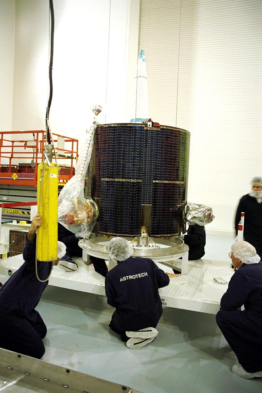
Lockheed Martin Missile Systems integration and test staff join NASA’s Lunar Prospector spacecraft atop the Trans Lunar Injection Module of the spacecraft at Astrotech, a commercial payload processing facility, in Titusville, Fla. The small robotic spacecraft, to be launched on an Athena II launch vehicle by Lockheed Martin, is designed to provide the first global maps of the Moon’s surface compositional elements and its gravitational and magnetic fields. The launch of Lunar Prospector is scheduled for Jan. 5, 1998 at 8:31 p.m
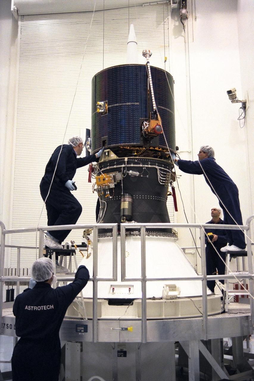
Lockheed Martin Missile Systems integration and test staff join NASA’s Lunar Prospector spacecraft to the Trans Lunar Injection Module of the spacecraft at Astrotech, a commercial payload processing facility, in Titusville, Fla. The small robotic spacecraft, to be launched on an Athena II launch vehicle by Lockheed Martin, is designed to provide the first global maps of the Moon’s surface compositional elements and its gravitational and magnetic fields. The launch of Lunar Prospector is scheduled for Jan. 5, 1998 at 8:31 p.m
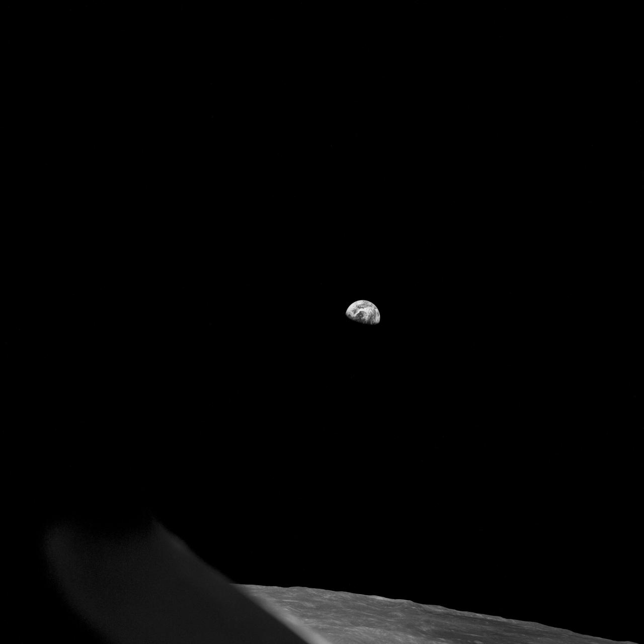
Apollo 8,Earth and Lunar Horizon. Image taken on Revolution 10 during Transearth Injection (TEI). Original Film Magazine was labeled D. Camera Data: 70mm Hasselblad. Lens: 80mm; F-Stop: F/11; Shutter Speed: 1/250 second. Film Type: Kodak SO-3400 Black and White,ASA 40. Flight Date: December 21-27,1968.

jsc2022e004237 (11/8/2021) --- A Preflight image of the Acoustics to Manipulate Fluids investigation, the acoustic tweezer apparatus is installed inside the Microgravity Science Glovebox Engineering Unit. The sample chamber, shown in the upper the right side, is where fluid droplets are injected via a septum located on the right side and manipulated by an ultrasonic transducer located on the left side. Image courtesy of Dr. Robert Lirette.
iss060e035085 (8/12/2019) --- European Space Agency (ESA) astronaut Luca Parmitano injects media into the culture bag of the Micro-15 investigation in the Japanese Experiment Module (JEM) abroad the International space Station (ISS). The goal of this investigation is to better understand the effects of gravity on the differentiation of mammalian cells using 3-D cultures of induced pluripotent stem (iPS) cells. This study investigates how exposure to microgravity fundamentally alters cell regulation and how these changes can affect the timing, progression, and outcomes of cell differentiation.
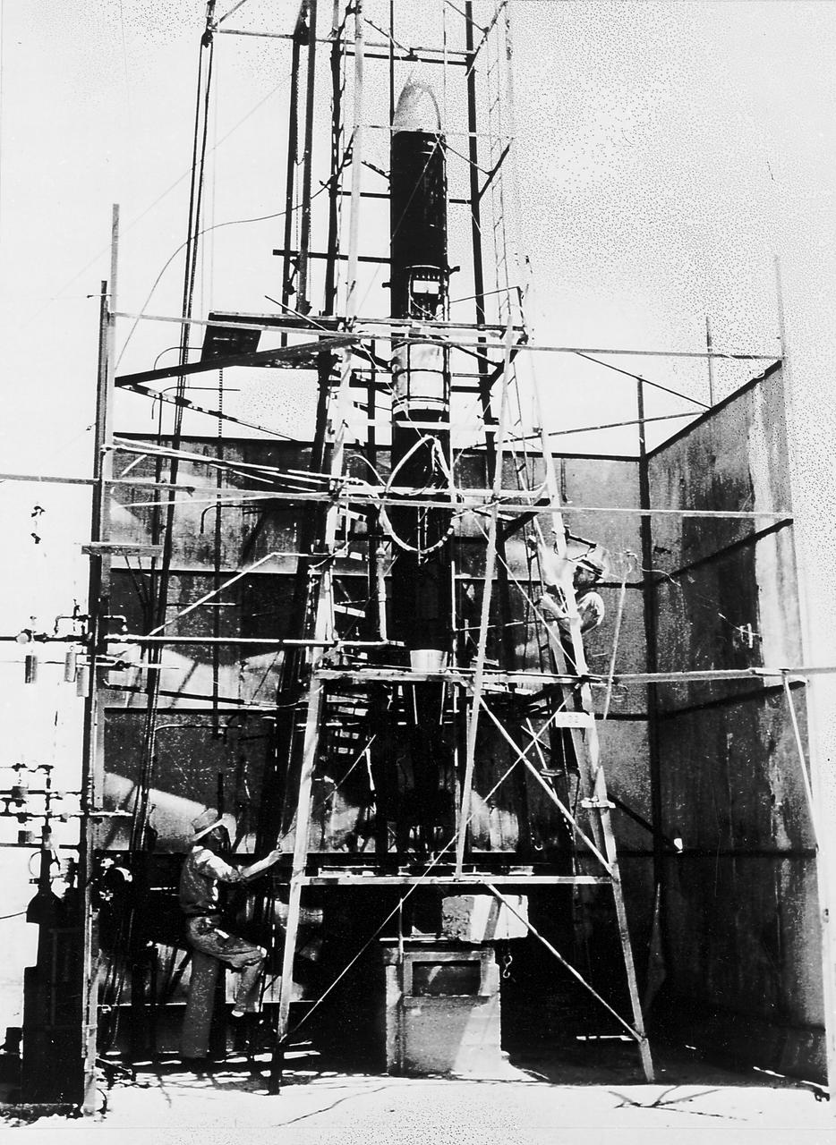
Goddard rocket in launching tower at Roswell, New Mexico, March 21, 1940. Fuel was injected by pumps from the fueling platform at left. From 1930 to 1941, Dr. Goddard made substantial progress in the development of progressively larger rockets, which attained altitudes of 2400 meters, and refined his equipment for guidance and control, his techniques of welding, and his insulation, pumps, and other associated equipment. In many respects, Dr. Goddard laid the essential foundations of practical rocket technology
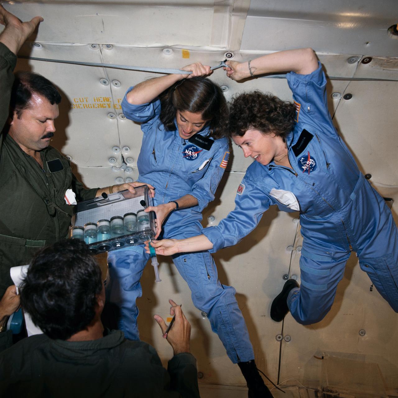
S85-42470 (16 Oct. 1985) --- Sharon Christa McAuliffe, right, and Barbara R. Morgan, participating in the Teacher-in-Space Project, team up with Bob Mayfield, a JSC aerospace educations specialist, to preview some experiments in zero-G. A KC-135 aircraft flies a special pattern to provide series of brief periods of weightlessness. McAuliffe, prime crew member for STS-51L, injects a hydroponic solution into a cylinder to review one of the experiments planned for the flight. Morgan is backup for McAuliffe on that mission. Photo credit: NASA
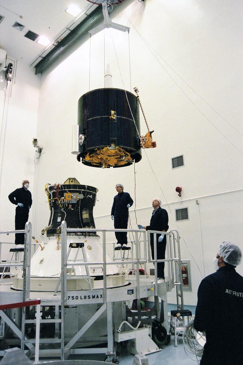
Lockheed Martin Missile Systems integration and test staff move NASA’s Lunar Prospector spacecraft over the Trans Lunar Injection Module of the spacecraft at Astrotech, a commercial payload processing facility, in Titusville, Fla. The small robotic spacecraft, to be launched on an Athena II launch vehicle by Lockheed Martin, is designed to provide the first global maps of the Moon’s surface compositional elements and its gravitational and magnetic fields. The launch of Lunar Prospector is scheduled for Jan. 5, 1998 at 8:31 p.m
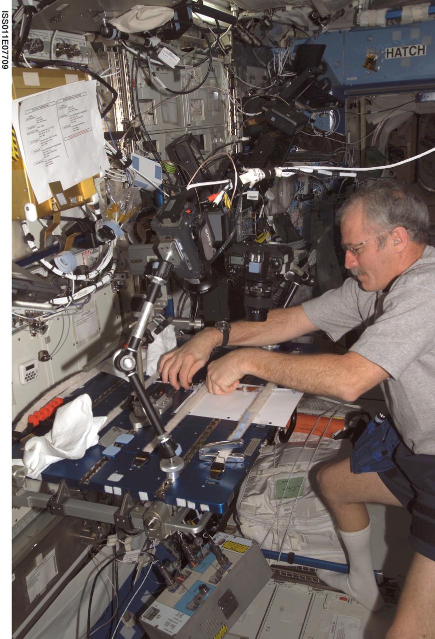
ISS011-E-07709 (2 June 2005) --- Astronaut John L. Phillips, Expedition 11 NASA ISS science officer and flight engineer, works with the Miscible Fluids in Microgravity (MFMG) payload activities in the Destiny laboratory of the International Space Station (ISS). At the work table, Phillips slowly injected tinted water into honey, as part of a thermal experiment.
This photograph depicts one of over thirty tests conducted on the Vortex Combustion Chamber Engine at Marshall Space Flight Center's (MSFC) test stand 115, a joint effort between NASA's MSFC and the U.S. Army AMCOM of Redstone Arsenal. The engine tests were conducted to evaluate an irnovative, "self-cooled", vortex combustion chamber, which relies on tangentially injected propellants from the chamber wall producing centrifugal forces that keep the relatively cold liquid propellants near the wall.

AS11-36-5299 (16 July 1969) --- This view of Earth showing clouds over water was photographed from the Apollo 11 spacecraft following translunar injection. While astronauts Neil A. Armstrong, commander, and Edwin E. Aldrin Jr., lunar module pilot, descended in the Lunar Module (LM) "Eagle" to explore the Sea of Tranquility region of the moon, astronaut Michael Collins, command module pilot, remained with the Command and Service Modules (CSM) "Columbia" in lunar orbit.
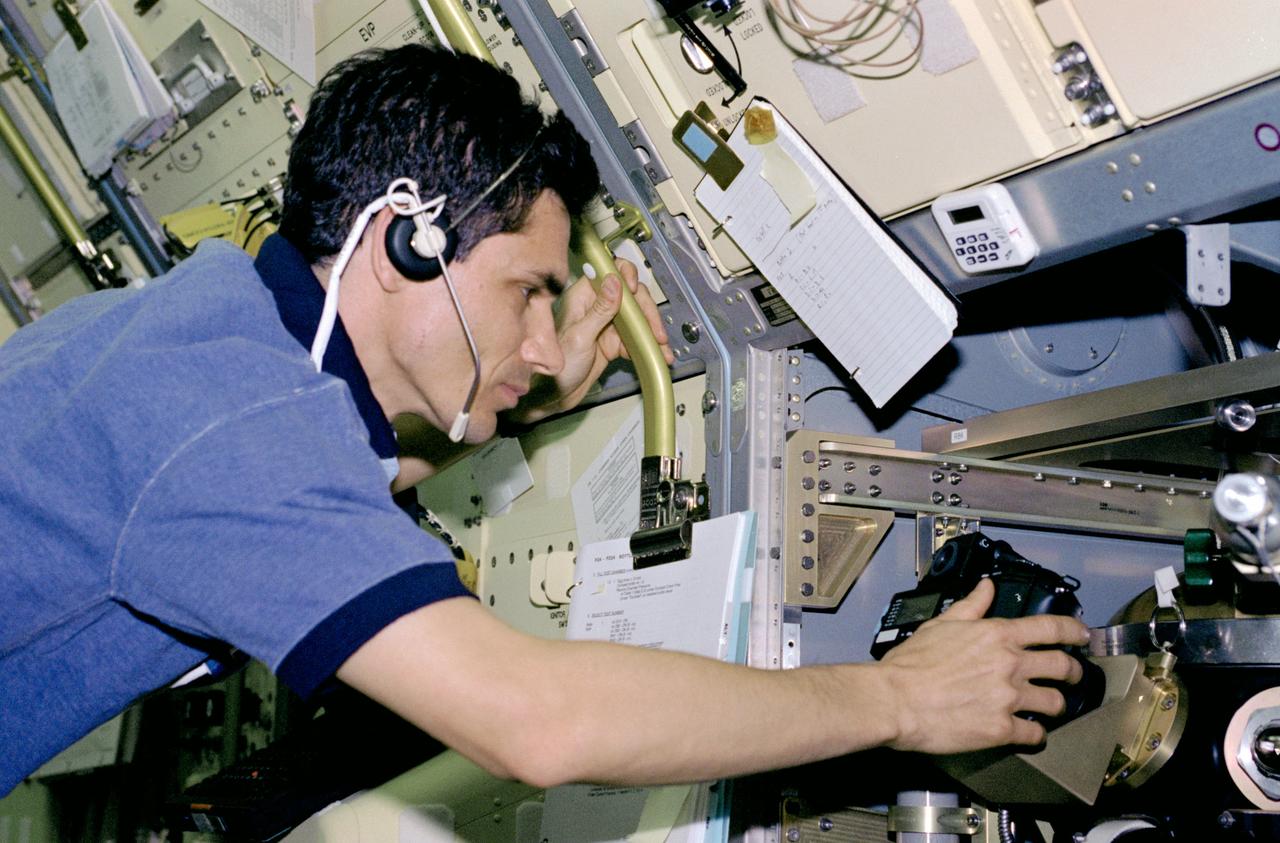
STS083-312-017 (4-8 April 1997) --- Payload specialist Gregory T. Linteris sets up a 35mm camera, one of three photographic/recording systems on the Drop Combustion Experiment (DCE) Apparatus. DCE is an enclosed chamber in which Helium-Oxygen fuel mixtures are injected and burned as single droplets. Combustion of fuel droplets is an important part of many operations, home heating, power production by gas turbines and combustion of gasoline in an automobile engine.
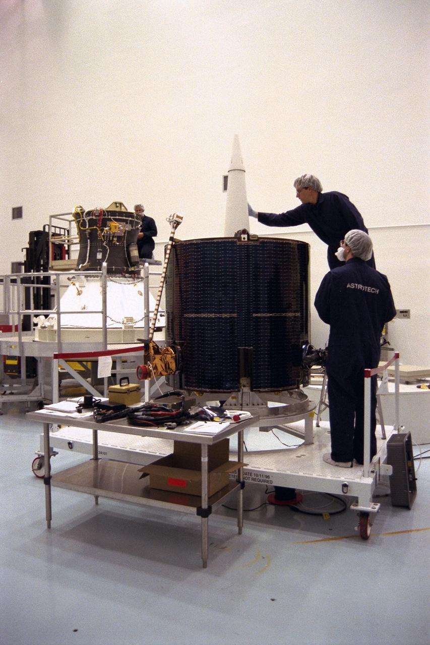
Lockheed Martin Missile Systems integration and test staff prepare NASA’s Lunar Prospector spacecraft for mating to the Trans Lunar Injection Module of the spacecraft at Astrotech, a commercial payload processing facility, in Titusville, Fla. The small robotic spacecraft, to be launched for NASA on an Athena II launch vehicle by Lockheed Martin, is designed to provide the first global maps of the Moon’s surface compositional elements and its gravitational and magnetic fields. The launch of Lunar Prospector is scheduled for Jan. 5, 1998 at 8:31 p.m
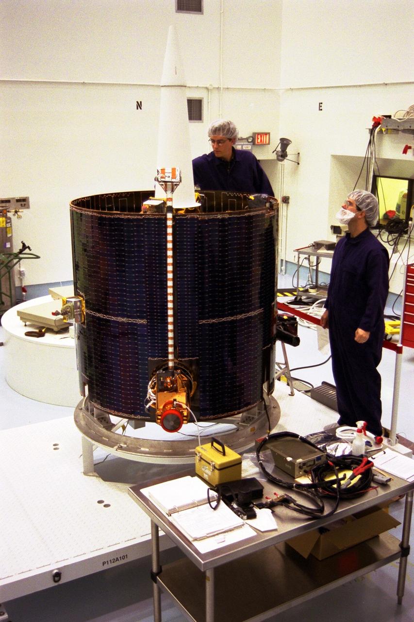
Lockheed Martin Missile Systems technicians prepare NASA’s Lunar Prospector spacecraft for mating to the Trans Lunar Injection Module of the spacecraft at Astrotech, a commercial payload processing facility, in Titusville, Fla. The small robotic spacecraft, to be launched for NASA on an Athena II launch vehicle by Lockheed Martin, is designed to provide the first global maps of the Moon’s surface compositional elements and its gravitational and magnetic fields. The launch of Lunar Prospector is scheduled for Jan. 5, 1998 at 8:31 p.m
Operators at the E-3 Test Stand at NASA's John C. Stennis Space Center completed 32 acoustics tests April 16-28, designed to gather critical information for future space launches. Stennis operators investigated lift-off acoustics that can damage space vehicle components by testing the benefits of injecting water onto the upper surface of the launch pad to suppress sound. The Stennis tests provided critical data to determine what can be gained from this approach.
NASA’s Lunar Prospector is prepared for mating to the Trans Lunar Injection Module of the spacecraft, seen in the background, at Astrotech, a commercial payload processing facility, in Titusville, Fla. The small robotic spacecraft, to be launched for NASA on an Athena II launch vehicle by Lockheed Martin, is designed to provide the first global maps of the Moon’s surface compositional elements and its gravitational and magnetic fields. The launch of Lunar Prospector is scheduled for Jan. 5, 1998 at 8:31 p.m
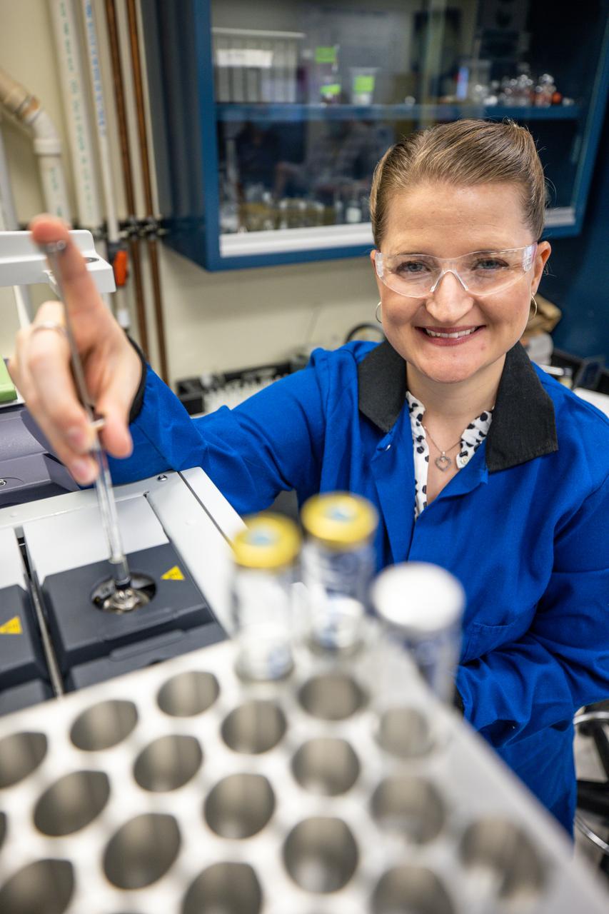
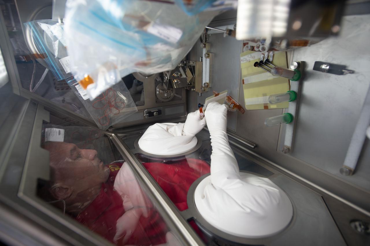
Senior analytical chemist Janelle Coutts injects a sample for gas chromatography-mass spectrometry analysis inside NASA Engineering’s Analytical Laboratories at Kennedy Space Center in Florida on July 7, 2021. One of seven branches in the NASA Laboratories, Development, and Testing Division, the Analytical Laboratories branch provides microscopic imagery and analysis through the use of a wide variety of microscopic techniques to identify contaminants and other urgent problems associated with aerospace flight hardware, ground support equipment, and related facilities.
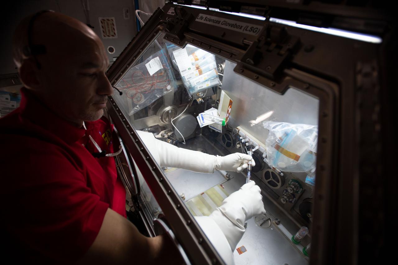
iss060e035097 (8/12/2019) --- European Space Agency (ESA) astronaut Luca Parmitano injects media into the culture bag of the Micro-15 investigation in the Japanese Experiment Module (JEM) abroad the International space Station (ISS). The goal of this investigation is to better understand the effects of gravity on the differentiation of mammalian cells using 3-D cultures of induced pluripotent stem (iPS) cells. This study investigates how exposure to microgravity fundamentally alters cell regulation and how these changes can affect the timing, progression, and outcomes of cell differentiation.
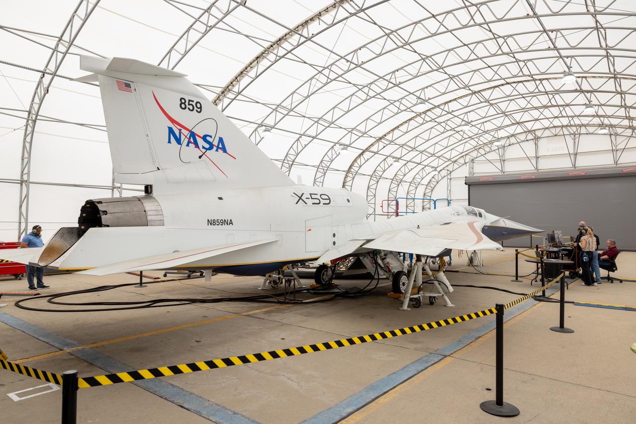
NASA’s X-59 quiet supersonic research aircraft successfully completed its “aluminum bird” systems test at Lockheed Martin’s Skunk Works facility in Palmdale, California. With NASA pilot James Less in the cockpit, the X-59 team simulated flight conditions from takeoff to landing – without ever leaving the ground. The test verified how the aircraft’s hardware and software work together, responding to pilot inputs and handling injected system failures. This milestone confirms the aircraft’s readiness for the next series of tests leading to first flight.
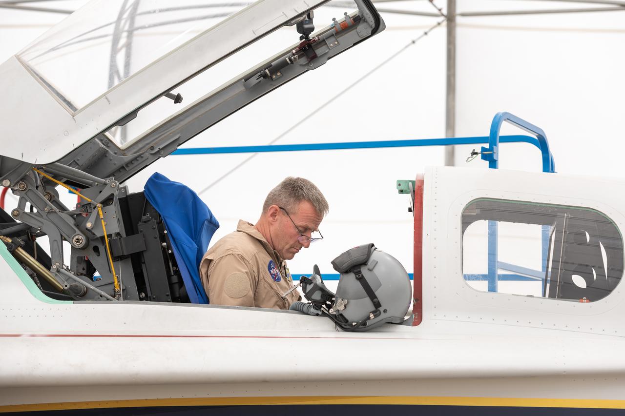
NASA’s X-59 quiet supersonic research aircraft successfully completed its “aluminum bird” systems test at Lockheed Martin’s Skunk Works facility in Palmdale, California. With NASA pilot James Less in the cockpit, the X-59 team simulated flight conditions from takeoff to landing – without ever leaving the ground. The test verified how the aircraft’s hardware and software work together, responding to pilot inputs and handling injected system failures. This milestone confirms the aircraft’s readiness for the next series of tests leading to first flight.
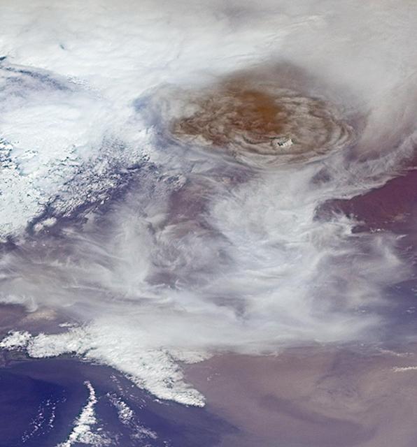
NASA Terra spacecraft captured this image of Grímsvötn, the most active of Iceland volcanoes, which began erupting around 5:30 p.m. local time 1730 UTC on Saturday, May 21, 2011, east of the capital city of Reykjavik.
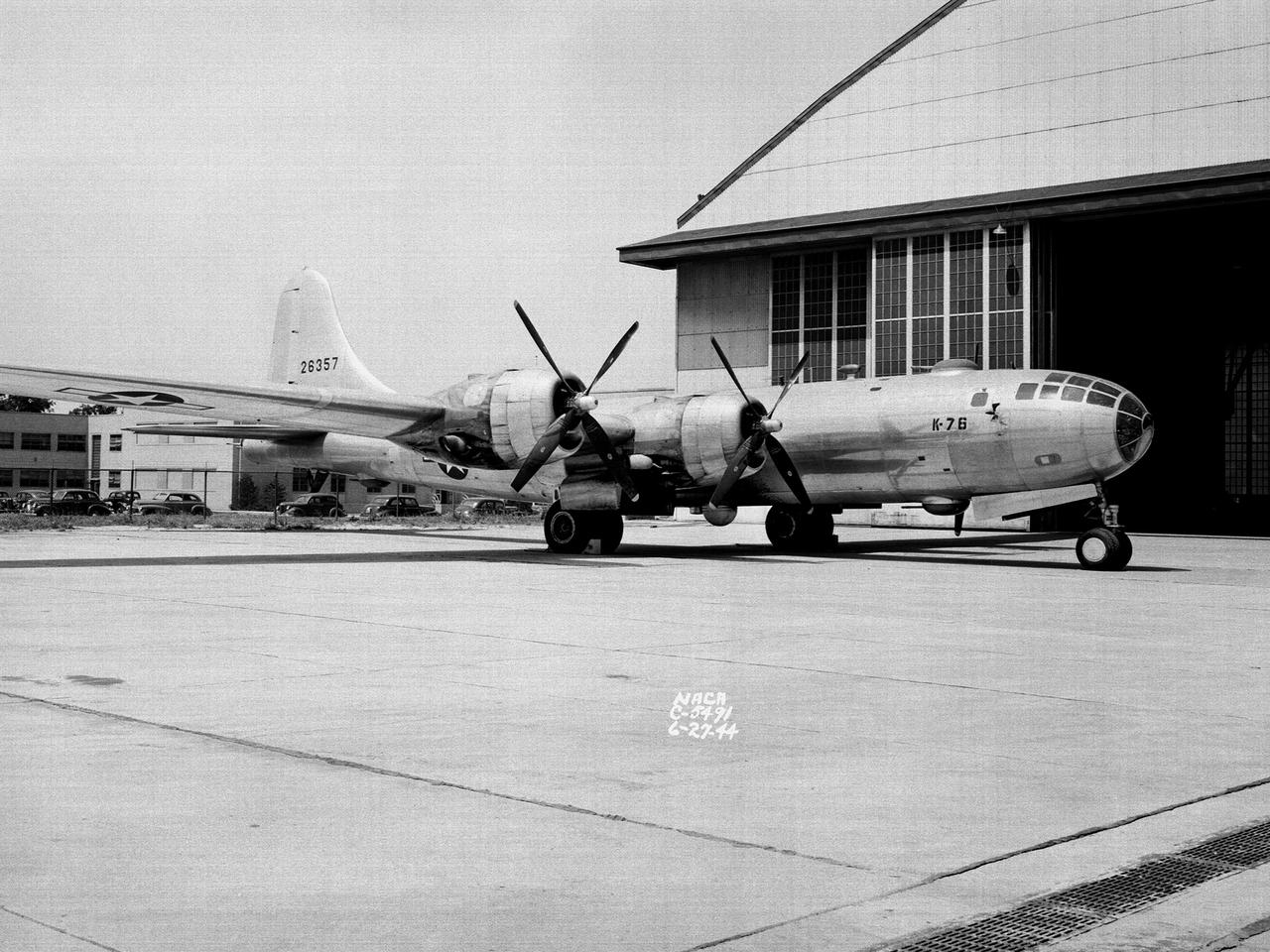
A Boeing B–29 Superfortress at the National Advisory Committee for Aeronautics (NACA) Aircraft Engine Research Laboratory in Cleveland, Ohio. The B–29 was the Army Air Forces’ deadliest weapon during the latter portion of World War II. The aircraft was significantly larger than previous bombers but could fly faster and higher. The B–29 was intended to soar above anti-aircraft fire and make pinpoint drops onto strategic targets. The bomber was forced to carry 20,000 pounds more armament than it was designed for. The extra weight pushed the B–29’s four powerful Wright R–3350 engines to their operating limits. The over-heating of the engines proved to be a dangerous problem. The military asked the NACA to tackle the issue. Full-scale engine tests on a R–3350 engine in the Prop House demonstrated that a NACA-designed impeller increased the flow rate of the fuel injection system. Altitude Wind Tunnel studies of the engine led to the reshaping of cowling inlet and outlet to improve airflow and reduce drag. Single-cylinder studies on valve failures were resolved by a slight extension of the cylinder head, and the Engine Research Building researchers combated uneven heating with a new fuel injection system. The modifications were then tried out on an actual B–29. The bomber arrived in Cleveland on June 22, 1944. The new injection impeller, ducted head baffles and instrumentation were installed on the bomber’s two left wing engines. Eleven test flights were flown over the next month with military pilots at the helm. Overall the flight tests corroborated the wind tunnel and test stand studies.
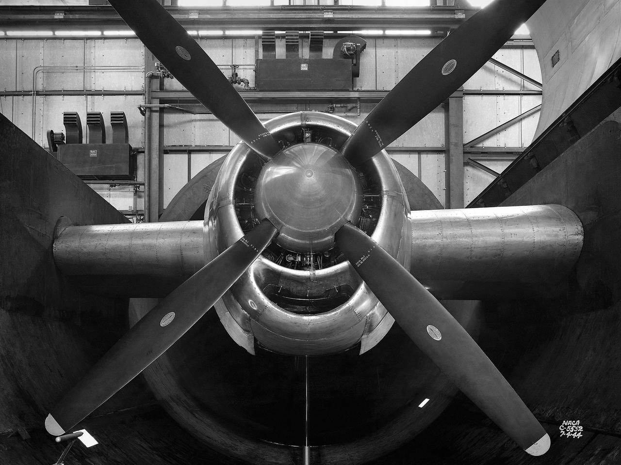
The resolution of the Boeing B-29 Superfortress’ engine cooling problems was one of the Aircraft Engine Research Laboratory’s (AERL) key contributions to the World War II effort. The B-29 leapfrogged previous bombers in size, speed, and altitude capabilities. The B–29 was intended to soar above anti-aircraft fire and make pinpoint bomb drops onto strategic targets. Four Wright Aeronautical R-3350 engines powered the massive aircraft. The engines, however, frequently strained and overheated due to payload overloading. This resulted in a growing number of engine fires that often resulted in crashes. The military asked the NACA to tackle the overheating issue. Full-scale engine tests on a R–3350 engine in the Prop House demonstrated that a NACA-designed impeller increased the fuel injection system’s flow rate. Single-cylinder studies resolved a valve failure problem by a slight extension of the cylinder head, and researchers in the Engine Research Building combated uneven heating with a new fuel injection system. Investigations during the summer of 1944 in the Altitude Wind Tunnel, which could simulate flight conditions at high altitudes, led to reduction of drag and improved air flow by reshaping the cowling inlet and outlet. The NACA modifications were then flight tested on a B-29 bomber that was brought to the AERL.
Chemist Trey Barnes prepares a gas sample for injection into a gas chromatography-mass spectrometry system preconcentrator for analyzing trace level gas contaminants inside NASA Engineering’s Analytical Laboratories at Kennedy Space Center in Florida on July 7, 2021. One of seven branches in the NASA Laboratories, Development, and Testing Division, the Analytical Laboratories branch provides microscopic imagery and analysis through the use of a wide variety of microscopic techniques to identify contaminants and other urgent problems associated with aerospace flight hardware, ground support equipment, and related facilities.

The Space Shuttle External Tank 120 is shown here in its vertical position in NASA’s Michoud Assembly Facility in New Orleans. Slated for launch on the Orbiter Discovery scheduled for next Spring, the tank is in position for its new foam application process on the liquid hydrogen tank-to-inter tank flange area, a tank structural connection point. The foam will be applied with an enhanced finishing procedure that requires two technicians, one for a new mold-injection procedure to the intertank’s ribbing and one for real-time videotaped surveillance of the process. Marshall Space Flight Center played a significant role in the development of the new application process designed to replace the possible debris shedding source previously used.
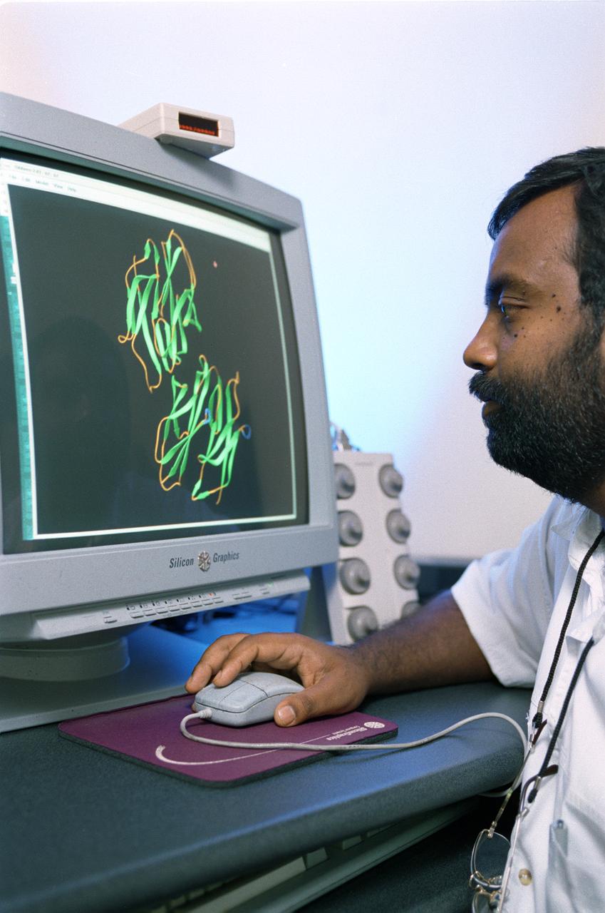
Diabetic patients may someday reduce their insulin injections and lead more normal lives because of new insights gained through innovative space research in which insulin crystals were grown on the Space Shuttle. Results from a 1994 insulin crystals growth experiment in space are leading to a new understanding of protein insulin. Lack of insulin is the cause of diabetes, a disease that accounts for one-seventh of the nation's health care costs. Champion Deivanaygam, a researcher at the Center for Macromolecular Crystallography at the University of Alabama in Birmingham, assists in this work. Photo credit: NASA/Marshall Space Flight Center (MSFC)

The Space Shuttle External Tank 120 is shown here during transfer in NASA’s Michoud Assembly Facility in New Orleans. Slated for launch on the Orbiter Discovery scheduled for next Spring, the tank will be erected vertically in preparation for its new foam application process on the liquid hydrogen tank-to-inter tank flange area, a tank structural connection point. The foam will be applied with an enhanced finishing procedure that requires two technicians, one for a new mold-injection procedure to the intertank’s ribbing and one for real-time videotaped surveillance of the process. Marshall Space Flight Center played a significant role in the development of the new application process designed to replace the possible debris shedding source previously used.
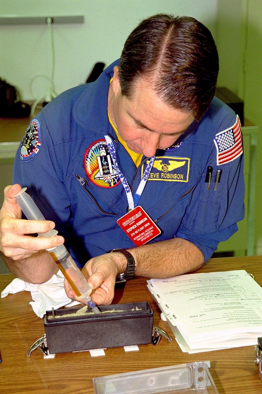
KENNEDY SPACE CENTER, FLA. -- STS-95 Mission Specialist Stephen K. Robinson injects water into the base of the seed container where plants will grow during the upcoming mission. This is part of the Biological Research in Canisters (BRIC) experiment which is at the SPACEHAB Payload Processing Facility, Cape Canaveral, Fla. This experiment will fly in SPACEHAB in Discovery’s payload bay. STS-95 is scheduled to launch from pad 39B at KSC on Oct. 29, 1998. The mission also includes research payloads such as the Spartan solar-observing deployable spacecraft, the Hubble Space Telescope Orbital Systems Test Platform, the International Extreme Ultraviolet Hitchhiker, as well as experiments on space flight and the aging process
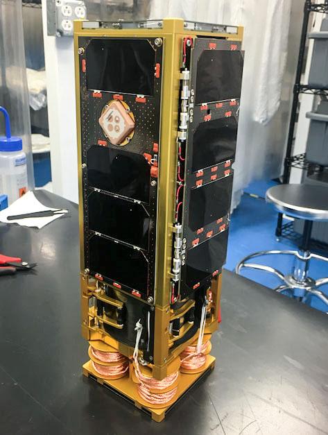
jsc2019e056548 (9/27/2019) --- Preflight overall view of SwampSat-II . SwampSat II measures very low frequency (VLF) wave propagation in Earth’s upper atmosphere using a novel antenna that has higher sensitivity than existing methods. The antenna system, developed by students at the University of Florida, launches in a 3-Unit CubeSat. Ground-based sources such as VLF transmitters and lightning injected VLF waves into the upper atmosphere, and measuring these waves is essential to understanding loss of energetic radiation belt particles. Image courtesy of: The SwampSat Team at University of Florida
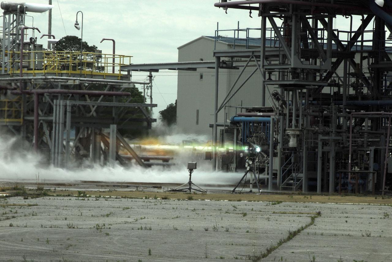
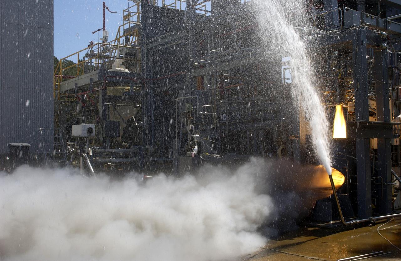
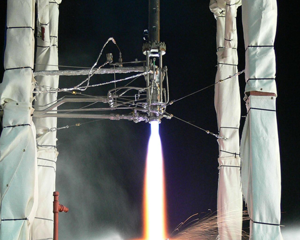
Chosen to power the upper stages of the new Ares I Crew Launch Vehicle (CLV) and the Ares V cargo segment, the J-2X engine is a stepped up version of the hydrogen/oxygen-fuelled Apollo-era J-2 engine. It was developed for NASA by Pratt & Whitney Rocketdyne (PWR), a business unit of United Technologies Corporation of Canoga Park, California. As seen in this photograph, the engine underwent a series of hot fire tests, performed on sub scale main injector hardware in the Test Stand 116 at Marshall Space Flight Center (MSFC). The injector is a major component of the engine that injects and mixes propellants in the combustion chamber, where they are ignited and burned to produce thrust.
Chosen to power the upper stages of the new Ares I Crew Launch Vehicle (CLV) and the Ares V cargo segment, the J-2X engine is a stepped up version of the hydrogen/oxygen-fuelled Apollo-era J-2 engine. It was developed for NASA by Pratt & Whitney Rocketdyne (PWR), a business unit of United Technologies Corporation of Canoga Park, California. As seen in this photograph, the engine underwent a series of hot fire tests, performed on sub scale main injector hardware in the Test Stand 116 at Marshall Space Flight Center (MSFC). The injector is a major component of the engine that injects and mixes propellants in the combustion chamber, where they are ignited and burned to produce thrust.
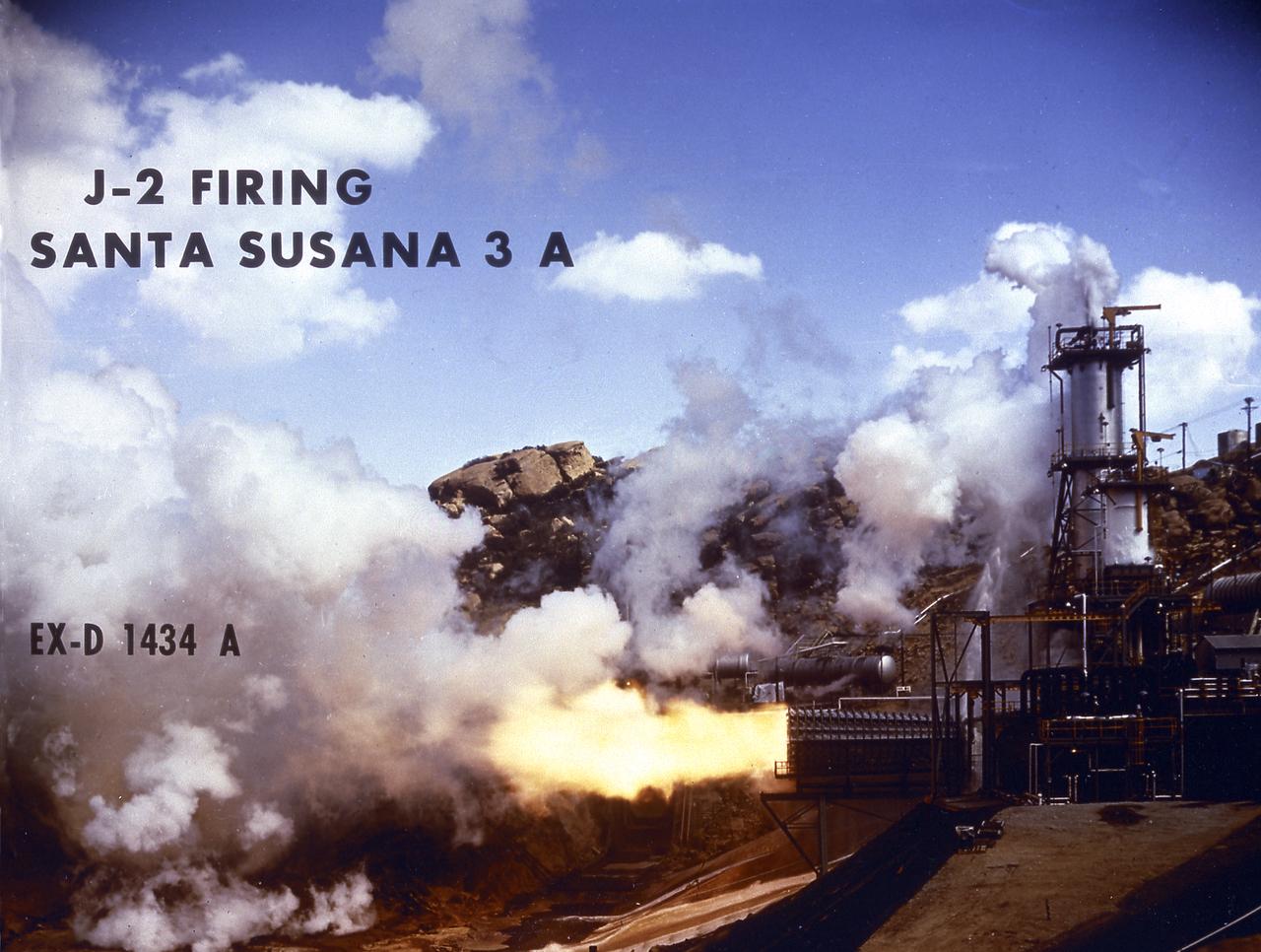
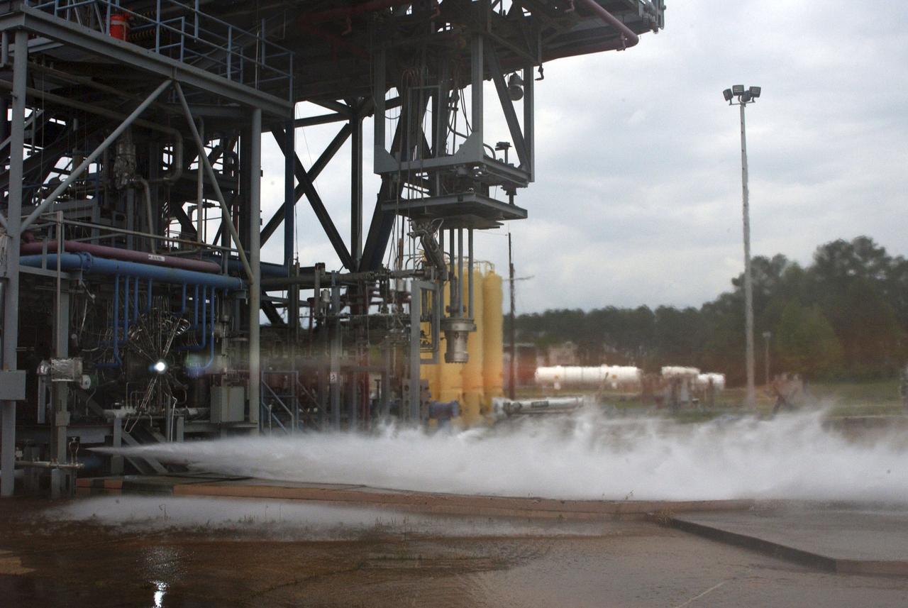
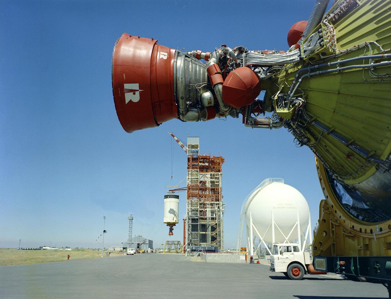
Smokeless flame juts from the diffuser of a unique vacuum chamber in which the upper stage rocket engine, the hydrogen fueled J-2, was tested at a simulated space altitude in excess of 60,000 feet. The smoke you see is actually steam. In operation, vacuum is established by injecting steam into the chamber and is maintained by the thrust of the engine firing through the diffuser. The engine was tested in this environment for start, stop, coast, restart, and full-duration operations. The chamber was located at Rocketdyne's Propulsion Field Laboratory, in the Santa Susana Mountains, near Canoga Park, California. The J-2 engine was developed by Rocketdyne for the Marshall Space Flight Center.
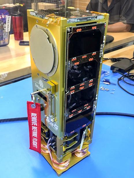
jsc2019e056549 (9/27/2019) --- Preflight overall view of SwampSat-II . SwampSat II measures very low frequency (VLF) wave propagation in Earth’s upper atmosphere using a novel antenna that has higher sensitivity than existing methods. The antenna system, developed by students at the University of Florida, launches in a 3-Unit CubeSat. Ground-based sources such as VLF transmitters and lightning injected VLF waves into the upper atmosphere, and measuring these waves is essential to understanding loss of energetic radiation belt particles. Image courtesy of: The SwampSat Team at University of Florida
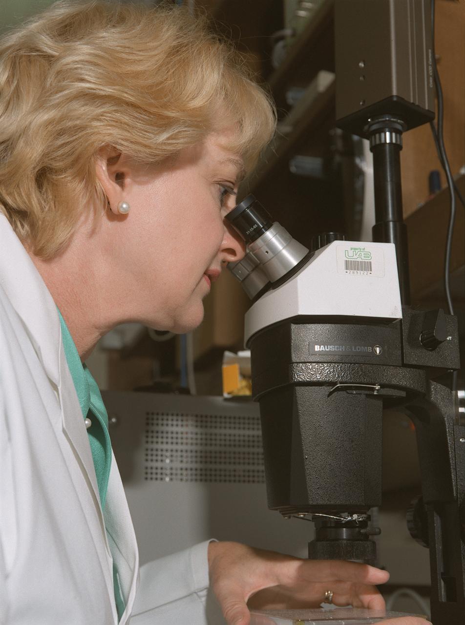
Diabetic patients may someday reduce their insulin injections and lead more normal lives because of new insights gained through irnovative space research in which insulin crystals were grown on the Space Shuttle. Results from a 1994 insulin crystal growth experiment in space are leading to a new understanding of protein insulin. Lack of insulin is the cause of diabetes, a desease that accounts for one-seventh of the nation's health care costs. Dr. Marianna Long, associate director of the Center of Macromolecular Crystallography at the University of Alabama at Birmingham, is a co-investigator on the research. Photo credit: NASA/Marshall Space Flight Center (MSFC)
NASA's Lunar Prospector is taken out of its crate at Astrotech, a commercial payload processing facility, in Titusville, Fla. The small robotic spacecraft, to be launched for NASA on an Athena 2 rocket by Lockheed Martin, is designed to provide the first global maps of the Moon's surface compositional elements and its gravitational and magnetic fields. While at Astrotech, Lunar Prospector will be fueled with its attitude control propellant and then mated to a Trans-Lunar Injection Stage which is a solid propellant upper stage motor. The combination will next be spin tested to verify proper balance, then encapsulated into an Athena nose fairing. Then the Lunar Prospector will be transported from Astrotech to Cape Canaveral Air Station and mated to an Athena rocket. The launch of Lunar Prospector is scheduled for Jan. 5, 1998 at 8:31 p.m
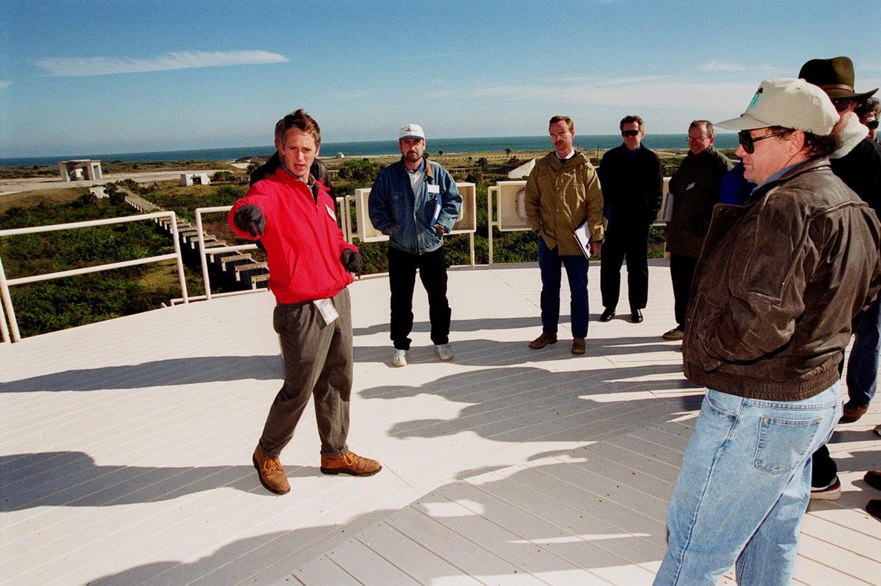
On top of the block house at Launch Complex 34, representatives from environmental and Federal agencies hear from Laymon Gray, with Florida State University, about the environmental research project that involves the Department of Defense, Environmental Protection Agency, Department of Energy and NASA in a groundwater cleanup effort. Concentrations of trichloroethylene solvent have been identified in the soil at the complex as a result of cleaning methods for rocket parts during the Apollo Program, which used the complex, in the 60s. The group formed the Interagency NDAPL Consortium (IDC) to study three contamination cleanup technologies: Six Phase Soil Heating, Steam Injection and In Situ Oxidation with Potassium Permanganate. All three methods may offer a way to remove the contaminants in months instead of decades. In the background (left) can be seen the cement platform and walkway from the block house to the pad. Beyond it is the Atlantic Ocean. KSC hosted a two-day conference that presented information and demonstrations of the three technologies being tested at the site
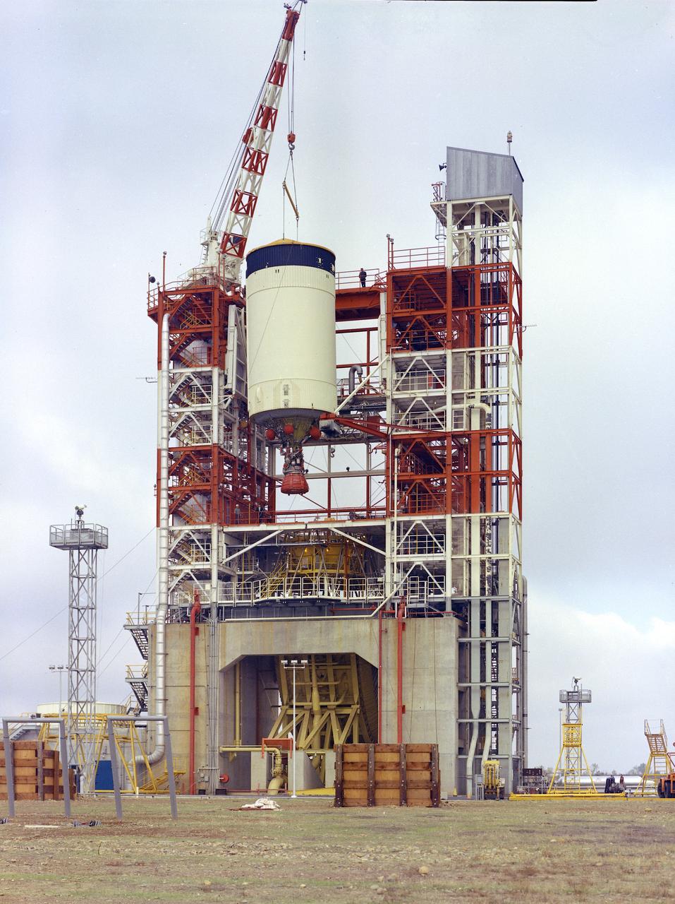
This image depicts the Saturn V S-IVB (third) stage for the Apollo 10 mission being removed from the Beta Test Stand 1 after its acceptance test at the Douglas Aircraft Company's Sacramento Test Operations (SACTO) facility. After the S-II (second) stage dropped away, the S-IVB (third) stage was ignited and burned for about two minutes to place itself and the Apollo spacecraft into the desired Earth orbit. At the proper time during this Earth parking orbit, the S-IVB stage was re-ignited to speed the Apollo spacecraft to escape velocity injecting it and the astronauts into a moon trajectory. Developed and manufactured by the Douglas Aircraft Company in California, the S-IVB stage measures about 21.5 feet in diameter, about 58 feet in length, and powered by a single 200,000-pound-thrust J-2 engine with a re-start capability. The S-IVB stage was also used on the second stage of the Saturn IB launch vehicle.

At Launch Complex 34, representatives from environmental and Federal agencies head for the block house during presentations about the environmental research project that involves the Department of Defense, Environmental Protection Agency, Department of Energy and NASA in a groundwater cleanup effort. Concentrations of trichloroethylene solvent have been identified in the soil at the complex as a result of cleaning methods for rocket parts during the Apollo Program, which used the complex, in the 60s. The group formed the Interagency NDAPL Consortium (IDC) to study three contamination cleanup technologies: Six Phase Soil Heating, Steam Injection and In Situ Oxidation with Potassium Permanganate. All three methods may offer a way to remove the contaminants in months instead of decades. KSC hosted a two-day conference that presented information and demonstrations of the three technologies being tested at the site
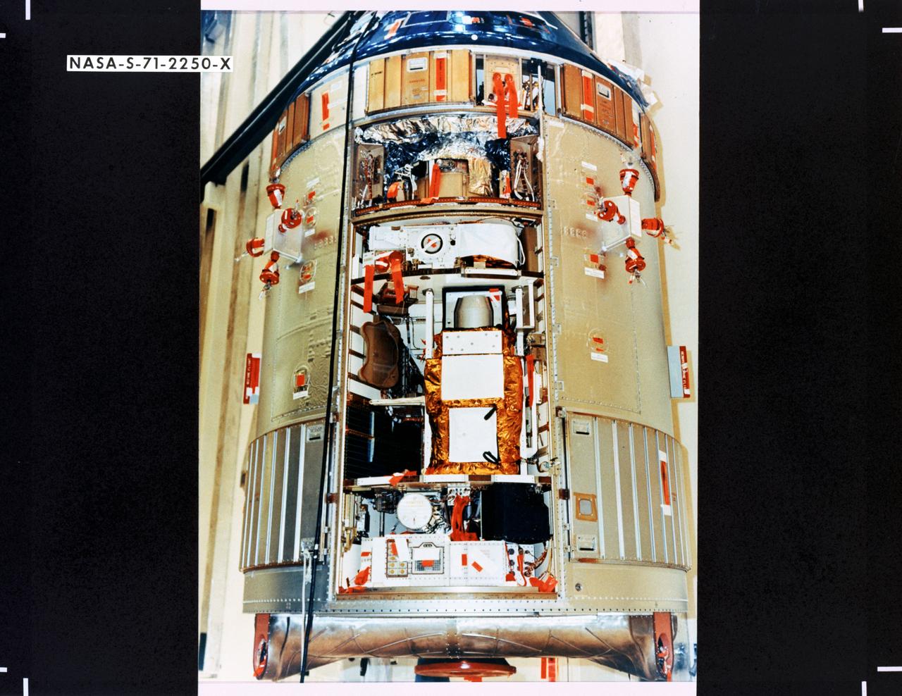
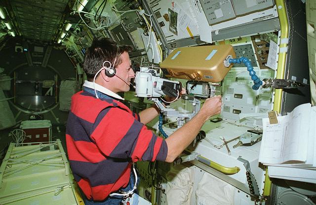
S71-2250X (June 1971) --- A close-up view of the Scientific Instrument Module (SIM) to be flown for the first time on the Apollo 15 lunar landing mission. Mounted in a previously vacant sector of the Apollo Service Module (SM), the SIM carries specialized cameras and instrumentation for gathering lunar orbit scientific data. SIM equipment includes a laser altimeter for accurate measurement of height above the lunar surface; a large-format panoramic camera for mapping, correlated with a metric camera and the laser altimeter for surface mapping; a gamma ray spectrometer on a 25-feet extendible boom; a mass spectrometer on a 21-feet extendible boom; X-ray and alpha particle spectrometers; and a subsatellite which will be injected into lunar orbit carrying a particle and magnetometer, and the S-Band transponder.
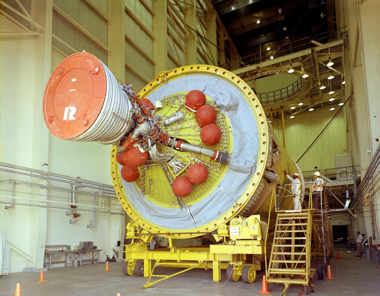
After the S-II (second) stage dropped away, the S-IVB (third) stage ignited and burned for about two minutes to place itself and the Apollo spacecraft into the desired Earth orbit. At the proper time during this Earth parking orbit, the S-IVB stage was re-ignited to speed the Apollo spacecraft to escape velocity, injecting it and the astronauts into a moon trajectory. Developed and manufactured by the Douglas Aircraft Company in Huntington, California, the S-IVB stage measures about 21.5 feet in diameter, about 58 feet in length and is powered by a single 200,000-pound-thrust J-2 engine with a re-start capability. The S-IVB stage was also used on the second stage of the Saturn IB launch vehicle. The fully-assembled S-IVB (third) stage for the AS-503 (Apollo 8 mission) launch vehicle is pictured in the Douglas' vertical checkout building.
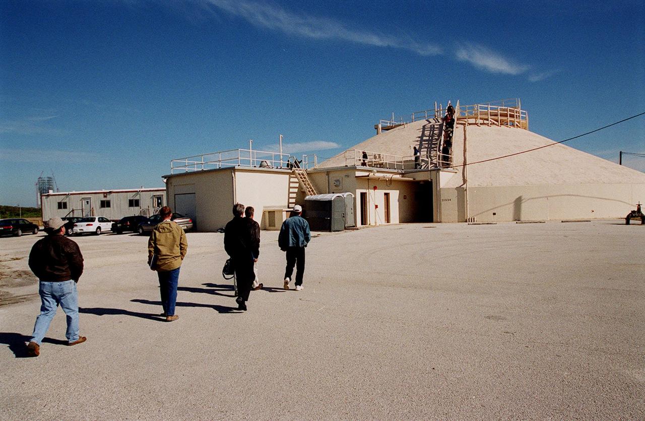
At Launch Complex 34, representatives from environmental and Federal agencies head for the block house during presentations about the environmental research project that involves the Department of Defense, Environmental Protection Agency, Department of Energy and NASA in a groundwater cleanup effort. Concentrations of trichloroethylene solvent have been identified in the soil at the complex as a result of cleaning methods for rocket parts during the Apollo Program, which used the complex, in the 60s. The group formed the Interagency NDAPL Consortium (IDC) to study three contamination cleanup technologies: Six Phase Soil Heating, Steam Injection and In Situ Oxidation with Potassium Permanganate. All three methods may offer a way to remove the contaminants in months instead of decades. KSC hosted a two-day conference that presented information and demonstrations of the three technologies being tested at the site
NASA's Lunar Prospector is taken out of its crate at Astrotech, a commercial payload processing facility, in Titusville, Fla. The small robotic spacecraft, to be launched for NASA on an Athena 2 rocket by Lockheed Martin, is designed to provide the first global maps of the Moon's surface compositional elements and its gravitational and magnetic fields. While at Astrotech, Lunar Prospector will be fueled with its attitude control propellant and then mated to a Trans-Lunar Injection Stage which is a solid propellant upper stage motor. The combination will next be spin tested to verify proper balance, then encapsulated into an Athena nose fairing. Then the Lunar Prospector will be transported from Astrotech to Cape Canaveral Air Station and mated to an Athena rocket. The launch of Lunar Prospector is scheduled for Jan. 5, 1998 at 8:31 p.m
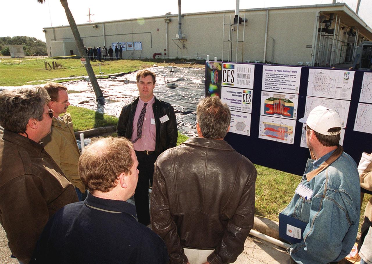
At Launch Complex 34, Greg Beyke, with Current Environmental Solutions, talks to representatives from environmental and federal agencies about the environmental research project that involves the Department of Defense, Environmental Protection Agency, Department of Energy and NASA in a groundwater cleanup effort. Concentrations of trichloroethylene solvent have been identified in the soil at the complex as a result of cleaning methods for rocket parts during the Apollo Program, which used the complex, in the 60s. The group formed the Interagency NDAPL Consortium (IDC) to study three contamination cleanup technologies: Six Phase Soil Heating, Steam Injection and In Situ Oxidation with Potassium Permanganate. All three methods may offer a way to remove the contaminants in months instead of decades. KSC hosted a two-day conference that presented information and demonstrations of the three technologies being tested at the site
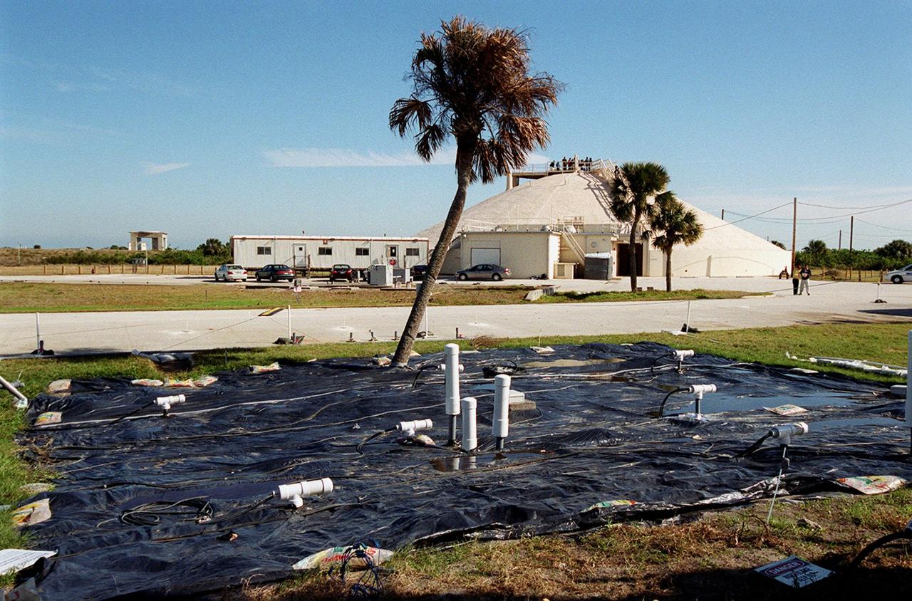
At Launch Complex 34, the Six-Phase Soil Heating site that is involved in a groundwater cleanup project can be seen. The project involves the Department of Defense, Environmental Protection Agency, Department of Energy and NASA. Concentrations of trichloroethylene solvent have been identified in the soil at the complex as a result of cleaning methods for rocket parts during the Apollo Program, which used the complex, in the 60s. The group formed the Interagency NDAPL Consortium (IDC) to study three contamination cleanup technologies: Six-Phase Soil Heating, Steam Injection and In Situ Oxidation with Potassium Permanganate. All three methods may offer a way to remove the contaminants in months instead of decades. In the background is the block house for the complex. KSC hosted a two-day conference that presented information and demonstrations of the three technologies being tested at the site
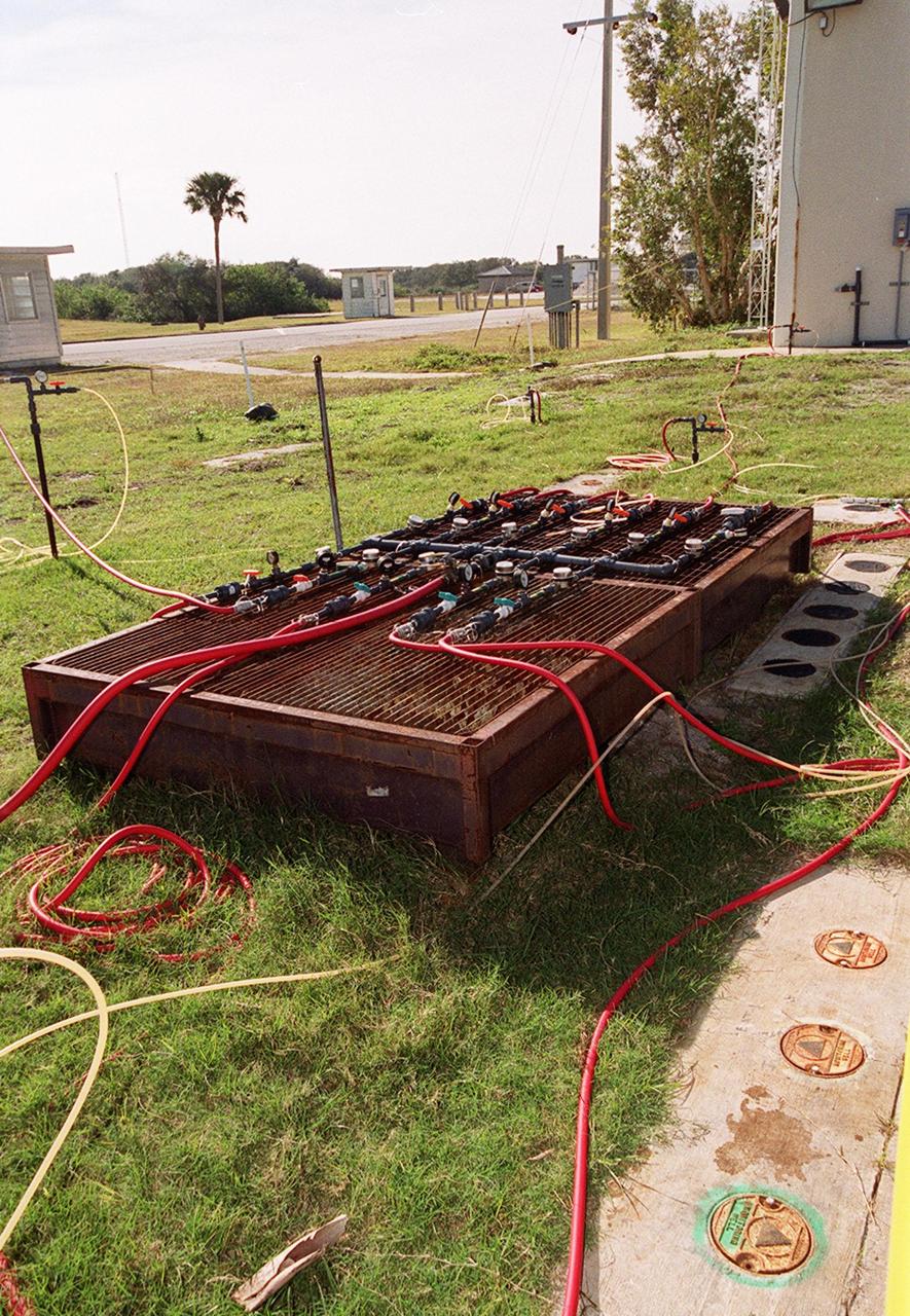
At Launch Complex 34, Cape Canaveral Air Station, several studies are under way for groundwater cleanup of trichloroethylene at the site. Shown here is monitoring equipment for one of the methods, potassium permanganate oxidation. Concentrations of trichloroethylene solvent have been identified in the soil at the complex as a result of cleaning methods for rocket parts during the Apollo Program in the 60s. The environmental research project involves the Department of Defense, Environmental Protection Agency, Department of Energy and NASA, who formed the Interagency NDAPL Consortium (IDC), to study three contamination cleanup technologies: Six Phase Soil Heating, Steam Injection and In Situ Oxidation with Potassium Permanganate. All three methods may offer a way to remove the contaminants in months instead of decades. KSC hosted a two-day conference that presented information and demonstrations of the three technologies for representatives from environmental and federal agencies

At Launch Complex 34, Greg Beyke, with Current Environmental Solutions, talks to representatives from environmental and federal agencies about the environmental research project that involves the Department of Defense, Environmental Protection Agency, Department of Energy and NASA in a groundwater cleanup effort. Concentrations of trichloroethylene solvent have been identified in the soil at the complex as a result of cleaning methods for rocket parts during the Apollo Program, which used the complex, in the 60s. The group formed the Interagency NDAPL Consortium (IDC) to study three contamination cleanup technologies: Six Phase Soil Heating, Steam Injection and In Situ Oxidation with Potassium Permanganate. All three methods may offer a way to remove the contaminants in months instead of decades. KSC hosted a two-day conference that presented information and demonstrations of the three technologies being tested at the site
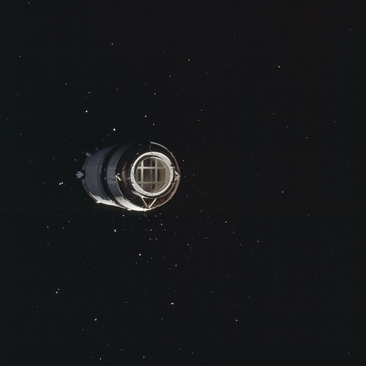
AS08-16-2583 (21 Dec. 1968) --- This is a photograph taken from the Apollo 8 spacecraft looking back at the Saturn V third (S-IVB) stage from which the spacecraft had just separated following trans-lunar injection. Attached to the S-IVB is the Lunar Module Test Article (LTA) which simulated the mass of a Lunar Module (LM) on the Apollo 8 lunar orbit mission. The 29-feet panels of the Spacecraft LM Adapter which enclosed the LTA during launch have already been jettisoned and are out of view. Sunlight reflected from small particles shows the "firefly" phenomenon which was reported by astronaut John H. Glenn Jr. during the first Earth-orbital flight, Mercury-Atlas 6 (MA-6) of the Mercury Program.

On top of the block house at Launch Complex 34, representatives from environmental and Federal agencies hear from Laymon Gray, with Florida State University, about the environmental research project that involves the Department of Defense, Environmental Protection Agency, Department of Energy and NASA in a groundwater cleanup effort. Concentrations of trichloroethylene solvent have been identified in the soil at the complex as a result of cleaning methods for rocket parts during the Apollo Program, which used the complex, in the 60s. The group formed the Interagency NDAPL Consortium (IDC) to study three contamination cleanup technologies: Six Phase Soil Heating, Steam Injection and In Situ Oxidation with Potassium Permanganate. All three methods may offer a way to remove the contaminants in months instead of decades. In the background (left) can be seen the cement platform and walkway from the block house to the pad. Beyond it is the Atlantic Ocean. KSC hosted a two-day conference that presented information and demonstrations of the three technologies being tested at the site

At Launch Complex 34, the Six-Phase Soil Heating site that is involved in a groundwater cleanup project can be seen. The project involves the Department of Defense, Environmental Protection Agency, Department of Energy and NASA. Concentrations of trichloroethylene solvent have been identified in the soil at the complex as a result of cleaning methods for rocket parts during the Apollo Program, which used the complex, in the 60s. The group formed the Interagency NDAPL Consortium (IDC) to study three contamination cleanup technologies: Six-Phase Soil Heating, Steam Injection and In Situ Oxidation with Potassium Permanganate. All three methods may offer a way to remove the contaminants in months instead of decades. In the background is the block house for the complex. KSC hosted a two-day conference that presented information and demonstrations of the three technologies being tested at the site

At Launch Complex 34, Cape Canaveral Air Station, several studies are under way for groundwater cleanup of trichloroethylene at the site. Shown here is monitoring equipment for one of the methods, potassium permanganate oxidation. Concentrations of trichloroethylene solvent have been identified in the soil at the complex as a result of cleaning methods for rocket parts during the Apollo Program in the 60s. The environmental research project involves the Department of Defense, Environmental Protection Agency, Department of Energy and NASA, who formed the Interagency NDAPL Consortium (IDC), to study three contamination cleanup technologies: Six Phase Soil Heating, Steam Injection and In Situ Oxidation with Potassium Permanganate. All three methods may offer a way to remove the contaminants in months instead of decades. KSC hosted a two-day conference that presented information and demonstrations of the three technologies for representatives from environmental and federal agencies
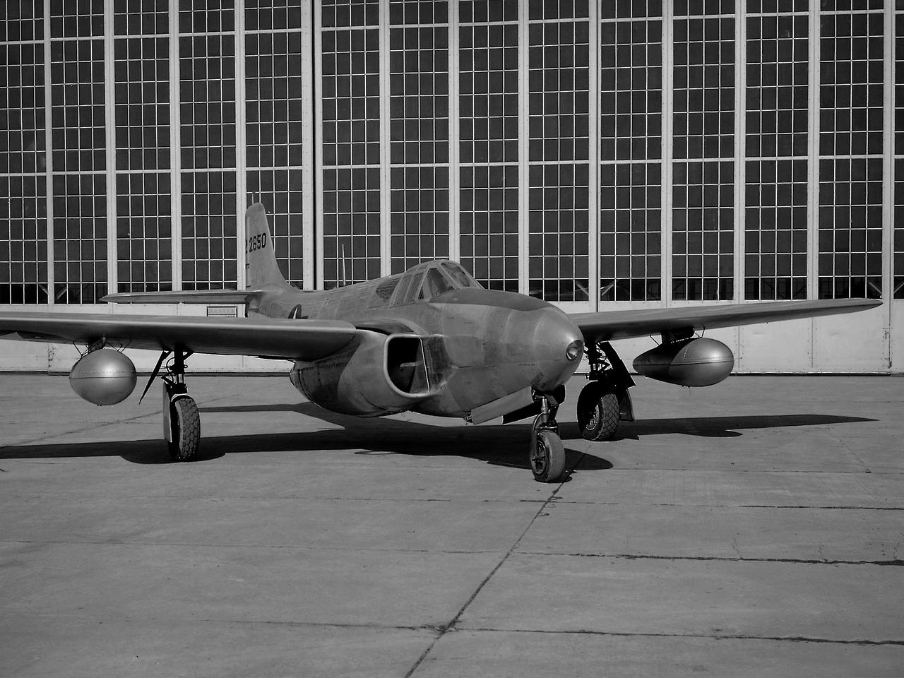
A Bell P-59B Airacomet sits beside the hangar at the National Advisory Committee for Aeronautics (NACA) Lewis Flight Propulsion Laboratory. In 1942 the Bell XP-59A Airacomet became the first jet aircraft in the US. The Airacomet incorporated centrifugal turbojet engines that were based on British plans secretly brought to the US in 1941. A Bell test pilot flew the XP-59A for the first time at Muroc Lake, California in October 1942. The General Electric I-16 engines proved to be problematic. In an effort to increase the engine performance, an Airacomet was secretly brought to Cleveland in early 1944 for testing in the Altitude Wind Tunnel. A series of tunnel investigations in February and March resulted in a 25-percent increase in the I-16 engine’s performance. Nonetheless, Bell’s 66 Airacomets never made it into combat. A second, slightly improved Airacomet, a P-59B, was transferred to NACA Lewis just after the war in September 1945. The P-59B was used over the next three years to study general jet thrust performance and thrust augmentation devices such as afterburners and water/alcohol injection. The P-59B flights determined the proper alcohol and water mixture and injection rate to produce a 21-percent increase in thrust. Since the extra boost would be most useful for takeoffs, a series of ground-based tests with the aircraft ensued. It was determined that the runway length for takeoffs could be reduced by as much as 15 percent. The P-59B used for the tests is now on display at the Air Force Museum at Wright Patterson.
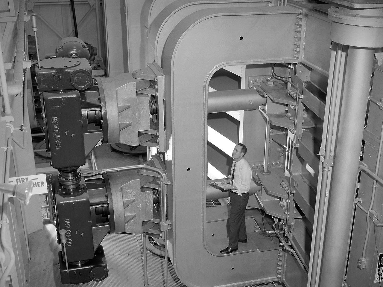
Screwjacks located on the exterior of the second throat section in the 10- by 10-Foot Supersonic Wind Tunnel at the National Aeronautics and Space Administration (NASA) Lewis Research Center. The 10- by 10 tunnel was the most powerful propulsion wind tunnel in the country when it began operating in 1956. The facility can generate wind speeds from Mach 3 to 3.5. A flexible wall nozzle located just upstream from the test section can be adjusted using screw jacks to produce the desired air flow. The 61-foot long second throat, seen here from the outside, was located just beyond the test section. It slows the supersonic air flow down to prevent shock waves. The second throat’s side walls can be adjusted up to three inches on each side using these electrically-driven screwjacks. The air and the 1.25-inch thick walls are cooled by water injection. During the 1960s the 10- by 10-foot tunnel supported the development of virtually all US launch vehicle systems. It was used for Atlas-Centaur, Saturn rockets, and Atlas-Agena testing.
This is a view of the Saturn V S-IVB (third) stage for the AS-209 (Apollo-Soyuz test project backup vehicle) on a transporter in the right foreground, and the S-IVB stage for AS-504 (Apollo 9 mission) being installed in the Beta Test Stand 1 at the SACTO facility in California. After the S-II (second) stage dropped away, the S-IVB (third) stage ignited and burned for about two minutes to place itself and the Apollo spacecraft into the desired Earth orbit. At the proper time during this Earth parking orbit, the S-IVB stage was re-ignited to speed the Apollo spacecraft to escape velocity and inject it and the astronauts into a moon trajectory. Developed and manufactured by the Douglas Aircraft Company in California, the S-IVB stage measures about 21.5 feet in diameter, about 58 feet in length, and is powered by a single 200,000-pound-thrust J-2 engine with a re-start capability. The S-IVB stage was also used on the second stage of the Saturn IB launch vehicle.
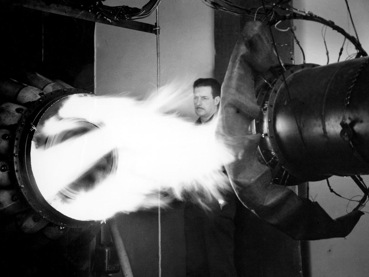
A mechanic watches the firing of a General Electric I-40 turbojet at the National Advisory Committee for Aeronautics (NACA) Lewis Flight Propulsion Laboratory. The military selected General Electric’s West Lynn facility in 1941 to secretly replicate the centrifugal turbojet engine designed by British engineer Frank Whittle. General Electric’s first attempt, the I-A, was fraught with problems. The design was improved somewhat with the subsequent I-16 engine. It was not until the engine's next reincarnation as the I-40 in 1943 that General Electric’s efforts paid off. The 4000-pound thrust I-40 was incorporated into the Lockheed Shooting Star airframe and successfully flown in June 1944. The Shooting Star became the US’s first successful jet aircraft and the first US aircraft to reach 500 miles per hour. NACA Lewis studied all of General Electric’s centrifugal turbojet models during the 1940s. In 1945 the entire Shooting Star aircraft was investigated in the Altitude Wind Tunnel. Engine compressor performance and augmentation by water injection; comparison of different fuel blends in a single combustor; and air-cooled rotors were studied. The mechanic in this photograph watches the firing of a full-scale I-40 in the Jet Propulsion Static Laboratory. The facility was quickly built in 1943 specifically in order to test the early General Electric turbojets. The I-A was secretly analyzed in the facility during the fall of 1943.
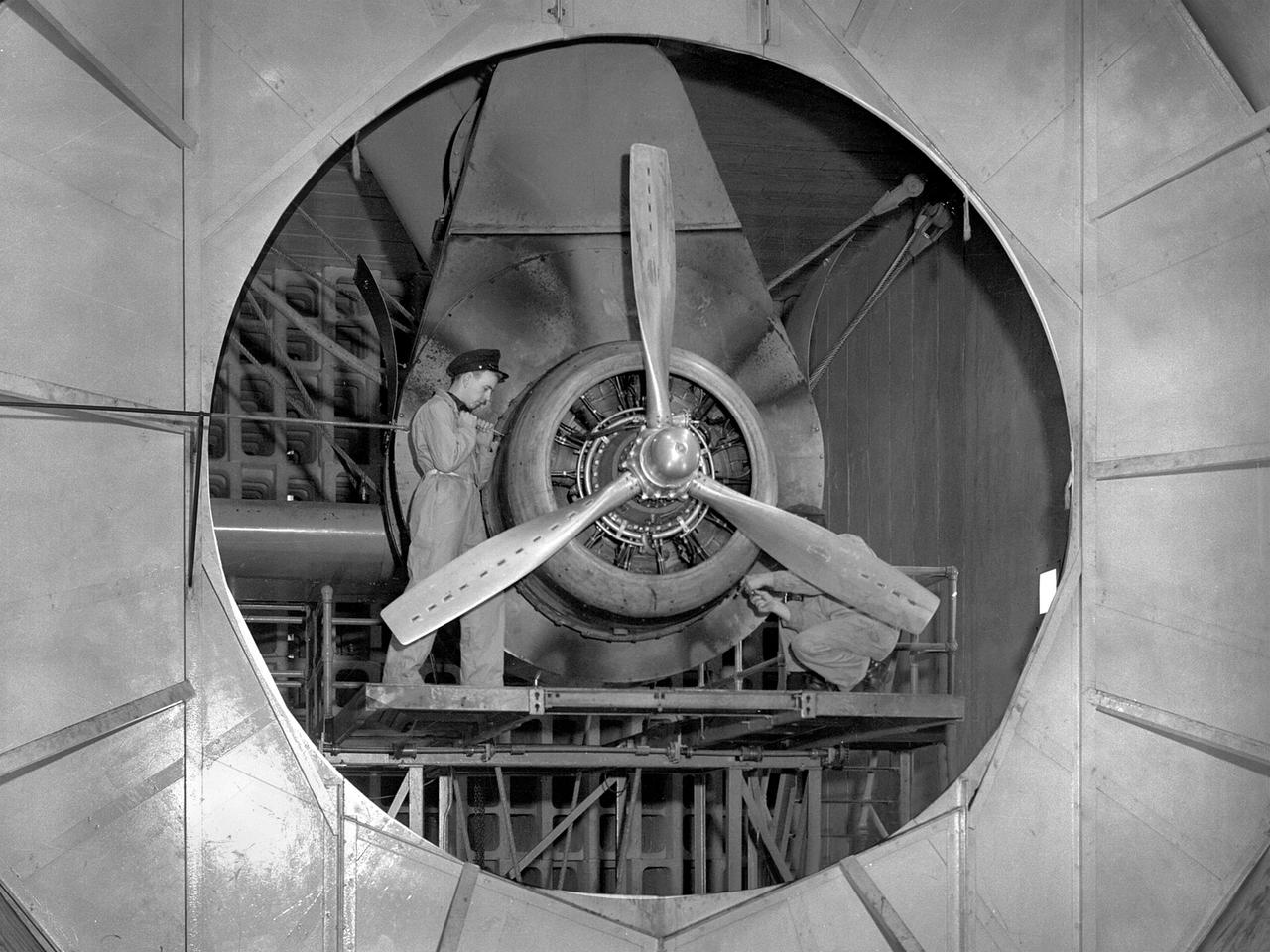
A Wright Aeronautical R–2600 Cyclone piston engine installed in the Engine Propeller Research Building, or Prop House, at the National Advisory Committee for Aeronautics (NACA) Aircraft Engine Research Laboratory. The R–2600 was among the most powerful engines that emerged during World War II. The engine, which was developed for commercial applications in 1939, was used to power the North American B–25 bomber and several other midsize military aircraft. The higher altitudes required by the military caused problems with the engine's cooling and fuel systems. The military requested that the Aircraft Engine Research Laboratory analyze the performance of the R–2600, improve its cooling system, and reduce engine knock. The NACA researchers subjected the engine to numerous tests in its Prop House. The R–2600 was the subject of the laboratory's first technical report, which was written by members of the Fuels and Lubricants Division. The Prop House contained soundproof test cells in which piston engines and propellers were mounted and operated at high powers. Electrically driven fans drew air through ducts to create a stream of cooling air over the engines. Researchers tested the performance of fuels, turbochargers, water-injection and cooling systems here during World War II. The facility was also investigated a captured German V–I buzz bomb during the war.
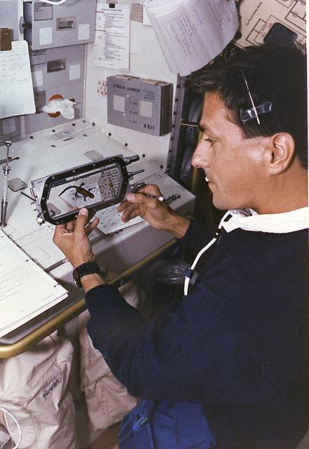
Astronaut Donald Thomas conducts the Fertilization and Embryonic Development of Japanese Newt in Space (AstroNewt) experiment at the Aquatic Animal Experiment Unit (AAEU) inside the International Microgravity Laboratory-2 (IML-2) science module. The AstroNewt experiment aims to know the effects of gravity on the early developmental process of fertilized eggs using a unique aquatic animal, the Japanese red-bellied newt. The newt egg is a large single cell at the begirning of development. The Japanese newt mates in spring and autumn. In late autumn, female newts enter hibernation with sperm in their body cavity and in spring lay eggs and fertilized them with the stored sperm. The experiment takes advantage of this feature of the newt. Groups of newts were sent to the Kennedy Space Center and kept in hibernation until the mission. The AAEU cassettes carried four newts aboard the Space Shuttle. Two newts in one cassette are treated by hormone injection on the ground to simulate egg laying. The other two newts are treated on orbit by the crew. The former group started maturization of eggs before launch. The effects of gravity on that early process were differentiated by comparison of the two groups. The IML-2 was the second in a series of Spacelab flights designed to conduct research by the international science community in a microgravity environment. Managed by the Marshall Space Flight Center, the IML-2 was launch on July 8, 1994 aboard the STS-65 Space Shuttle Orbiter Columbia mission.
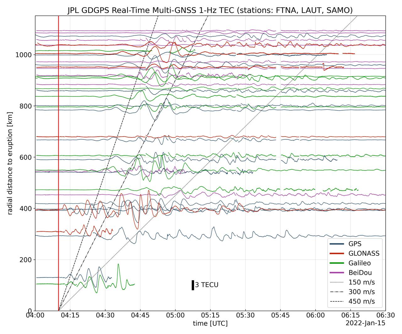
Real-time data collected by the Global Differential Global Positioning System network, operated by NASA's Jet Propulsion Laboratory, shows the atmospheric signature of the Hunga Tonga Hunga Ha'apai volcanic eruption in Tonga on Jan. 15, 2022. The data is a measure of the density of electrons (known as total electron content units, or TECU) in the ionosphere – the outermost layer of the atmosphere, which starts between 50 and 56 miles (80 to 90 kilometers) above Earth's surface. Navigation radio signals, like those received by location sensors on smartphones, are broadcast by global navigation satellite systems (GNSS) and experience delays when passing through the ionosphere. The extent of the delay depends on the density of electrons within the path of the GNSS signal in this atmospheric layer. When an explosive event such as a volcanic eruption or large earthquake injects energy into the atmosphere, the pressure waves from that event change the electron density in the ionosphere. These perturbations show up as tiny changes to the delays that GNSS radio signals usually experience as they pass through the atmosphere. The vertical red line in the data plot indicates the time of the eruption. The horizontal squiggles show electron density profiles picked up in the signals of four GNSS constellations, or groups of satellites: GPS, GLONASS, Galileo, and BeiDou. The slanted dashed and dotted lines indicate the velocity of waves. https://photojournal.jpl.nasa.gov/catalog/PIA24905
![A researcher at the National Advisory Committee for Aeronautics (NACA) Aircraft Engine Research Laboratory studies the fuel ignition process. Improved fuels and lubrication was an area of particular emphasis at the laboratory during World War II. The military sought to use existing types of piston engines in order to get large numbers of aircraft into the air as quickly as possible. To accomplish its goals, however, the military needed to increase the performance of these engines without having to wait for new models or extensive redesigns. The Aircraft Engine Research Laboratory was called on to lead this effort. The use of superchargers successfully enhanced engine performance, but the resulting heat increased engine knock [fuel detonation] and structural wear. These effects could be offset with improved cooling, lubrication, and fuel mixtures. The NACA researchers in the Fuels and Lubrication Division concentrated on new synthetic fuels, higher octane fuels, and fuel-injection systems. The laboratory studied 16 different types of fuel blends during the war, including extensive investigations of triptane and xylidine.](https://images-assets.nasa.gov/image/GRC-1943-C-02124/GRC-1943-C-02124~medium.jpg)
A researcher at the National Advisory Committee for Aeronautics (NACA) Aircraft Engine Research Laboratory studies the fuel ignition process. Improved fuels and lubrication was an area of particular emphasis at the laboratory during World War II. The military sought to use existing types of piston engines in order to get large numbers of aircraft into the air as quickly as possible. To accomplish its goals, however, the military needed to increase the performance of these engines without having to wait for new models or extensive redesigns. The Aircraft Engine Research Laboratory was called on to lead this effort. The use of superchargers successfully enhanced engine performance, but the resulting heat increased engine knock [fuel detonation] and structural wear. These effects could be offset with improved cooling, lubrication, and fuel mixtures. The NACA researchers in the Fuels and Lubrication Division concentrated on new synthetic fuels, higher octane fuels, and fuel-injection systems. The laboratory studied 16 different types of fuel blends during the war, including extensive investigations of triptane and xylidine.
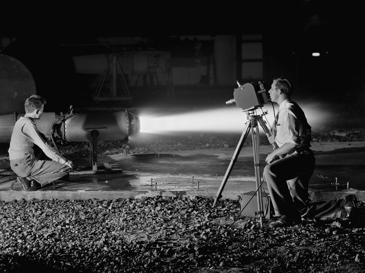
A National Advisory Committee for Aeronautics (NACA) photographer films the test of a ramjet engine at the Lewis Flight Propulsion Laboratory. The laboratory had an arsenal of facilities to test the engines and their components, and immersed itself in the study of turbojet and ramjet engines during the mid-1940s. Combustion, fuel injection, flameouts, and performance at high altitudes were of particular interest to researchers. They devised elaborate schemes to instrument the engines in order to record temperature, pressure, and other data. Many of the tests were also filmed so Lewis researchers could visually review the combustion performance along with the data. The photographer in this image was using high-speed film to document a thrust augmentation study at Lewis’ Jet Static Propulsion Laboratory. The ramjet in this photograph was equipped with a special afterburner as part of a general effort to improve engine performance. Lewis’ Photo Lab was established in 1942. The staff was expanded over the next few years as more test facilities became operational. The Photo Lab’s staff and specialized equipment have been key research tools for decades. They accompany pilots on test flights, use high-speed cameras to capture fleeting processes like combustion, and work with technology, such as the Schlieren camera, to capture supersonic aerodynamics. In addition, the group has documented construction projects, performed publicity work, created images for reports, and photographed data recording equipment.
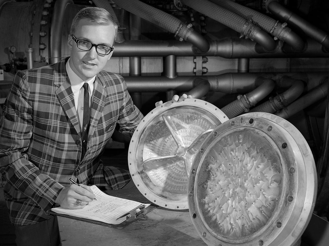
Dan Sokolowski worked as an engineering coop student at the National Aeronautics and Space Administration (NASA) Lewis Research Center from 1962 to 1966 while earning his Mechanical Engineering degree from Purdue. At the time of this photograph Sokolowski had just been hired as a permanent NASA employee in the Chemical Rocket Evaluation Branch of the Chemical Rocket Division. He had also just won a regional American Institute of Aeronautics and Astronautics competition for his paper on high and low-frequency combustion instability. The resolution of the low-frequency combustion instability, or chugging, in liquid hydrogen rocket systems was one of Lewis’ more significant feats of the early 1960s. In most rocket engine combustion chambers, the pressure, temperature, and flows are in constant flux. The engine is considered to be operating normally if the fluctuations remain random and within certain limits. Lewis researchers used high-speed photography to study and define Pratt and Whitney’s RL-10’s combustion instability by throttling the engine under the simulated flight conditions. They found that the injection of a small stream of helium gas into the liquid-oxygen tank immediately stabilized the system. Sokolowski’s later work focused on combustion in airbreathing engines. In 1983 was named Manager of a multidisciplinary program aimed at improving durability of combustor and turbine components. After 39 years Sokolowski retired from NASA in September 2002.
Astronaut Donald Thomas conducts the Fertilization and Embryonic Development of Japanese Newt in Space (AstroNewt) experiment at the Aquatic Animal Experiment Unit (AAEU) inside the International Microgravity Laboratory-2 (IML-2) science module. The AstroNewt experiment aims to know the effects of gravity on the early developmental process of fertilized eggs using a unique aquatic animal, the Japanese red-bellied newt. The newt egg is a large single cell at the begirning of development. The Japanese newt mates in spring and autumn. In late autumn, female newts enter hibernation with sperm in their body cavity and in spring lay eggs and fertilize them with the stored sperm. The experiment takes advantage of this feature of the newt. Groups of newts were sent to the Kennedy Space Center and kept in hibernation until the mission. The AAEU cassettes carried four newts aboard the Space Shuttle. Two newts in one cassette are treated by hormone injection on the ground to simulate egg laying. The other two newts are treated on orbit by the crew. The former group started maturization of eggs before launch. The effects of gravity on that early process were differentiated by comparison of the two groups. The IML-2 was the second in a series of Spacelab flights designed to conduct research by the international science community in a microgravity environment. Managed by the Marshall Space Flight Center, the IML-2 was launched on July 8, 1994 aboard the STS-65 Space Shuttle mission, Orbiter Columbia.
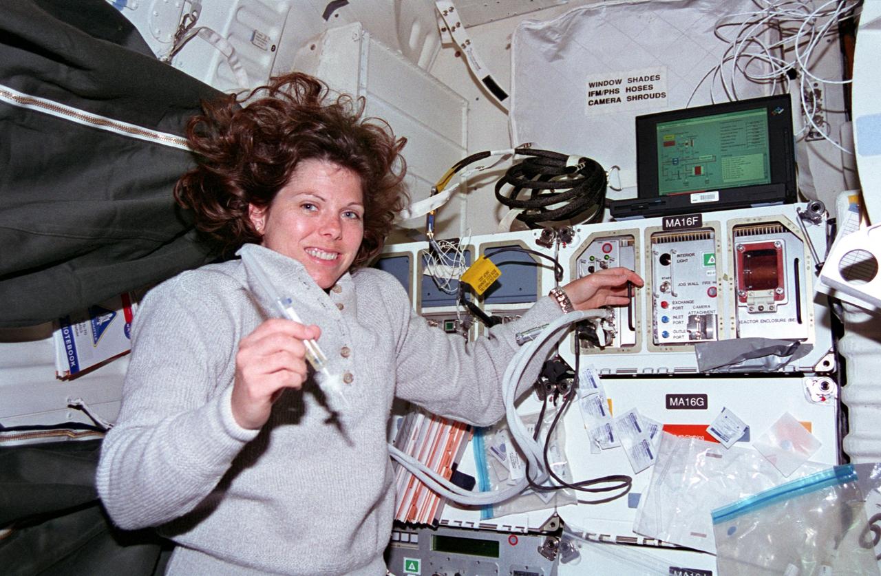
STS070-301-025 (13-22 July 1995) --- Astronaut Mary Ellen Weber works with a syringe related to the Bioreactor Development System (BDS). The almost weightless state of space travel provides life science researchers with the opportunity to grow cells into three-dimensional tissue pieces that are not achievable using conventional tissue culture methods on Earth. At specified times during the STS-70 mission, crew members injected color producing substances to document fluid movement in the reactor, and various-sized beads to estimate the tissue size that could be supported in the Bioreactor. The photo was among NASA's first release of still photography from the STS-70 mission. The mission was launched from the Kennedy Space Center (KSC) on July 13, 1995, and ended when Discovery landed on Runway 33 there on July 22, 1995. The crew members were astronauts Terence T. (Tom) Henricks, commander; Kevin R. Kregel, pilot; and Donald A. Thomas, Nancy J. Currie and Weber, all mission specialists.

Researchers from NASA's Jet Propulsion Laboratory in Southern California and the National Oceanic and Atmospheric Administration (NOAA) analyzed vertical land motion – also known as uplift and subsidence – along the California coast between 2015 and 2023. They detailed where land beneath major coastal cities, including parts of San Francisco, Los Angeles, and San Diego, is sinking (indicated in blue in this visualization of the data). Locations of uplift (shown in red) were also observed. Causes for the motion include human-driven activities such as groundwater withdrawal and wastewater injection as well as natural dynamics like tectonic activity. Understanding these local elevation changes can help communities adapt to rising sea levels in their area. The researchers pinpointed hot spots – including cities, beaches, and aquifers – at greater exposure to rising seas in coming decades. Sea level rise can exacerbate issues like nuisance flooding and saltwater intrusion. To gather the data, the researchers employed a remote sensing technique called interferometric synthetic aperture radar (InSAR), which combines two or more 3D observations of the same region to reveal surface motion down to fractions of inches. They used the radars on the ESA (European Space Agency) Sentinel-1 satellites, as well as motion velocity data from ground-based receiving stations in the Global Navigation Satellite System. https://photojournal.jpl.nasa.gov/catalog/PIA25530
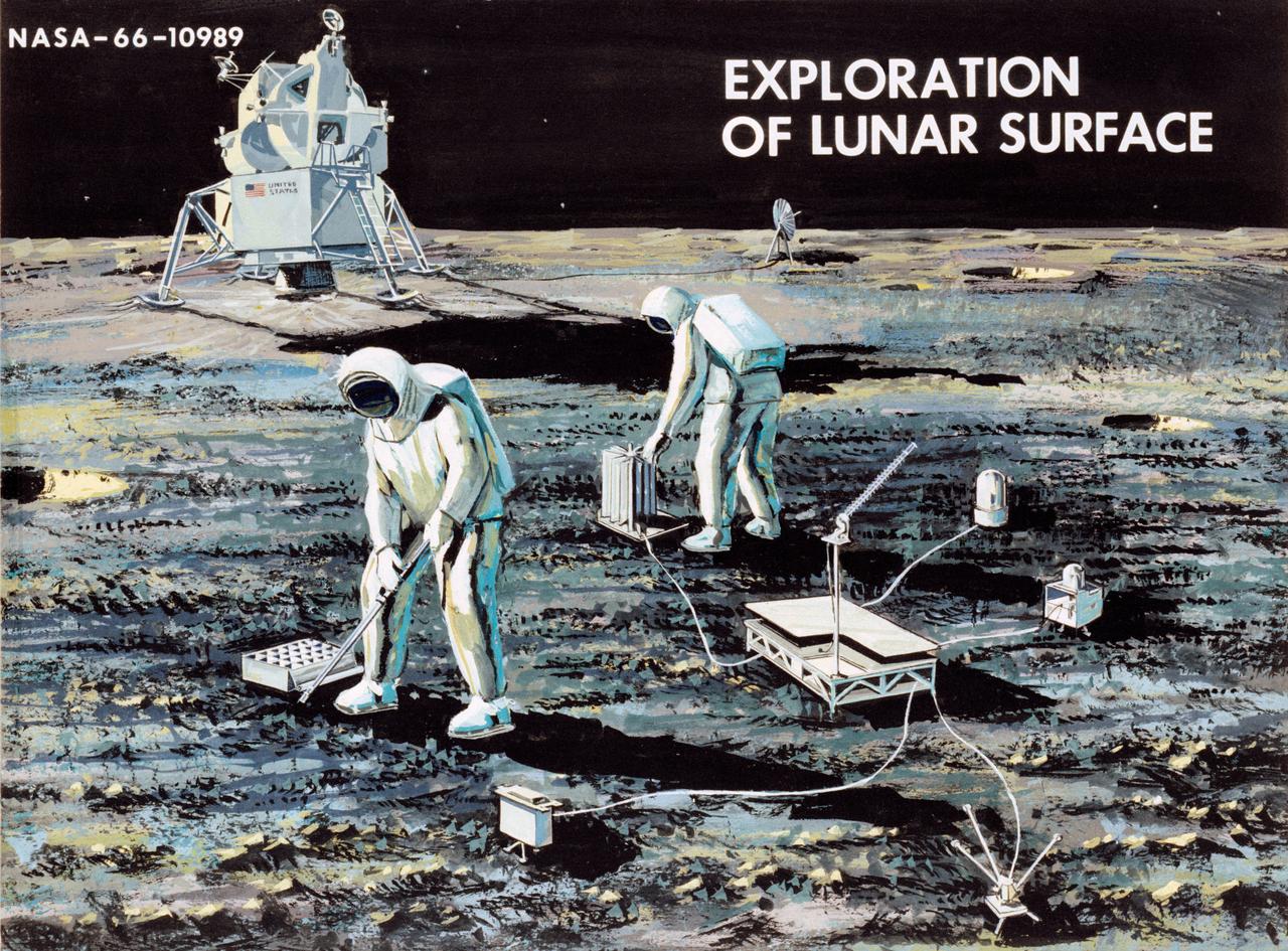
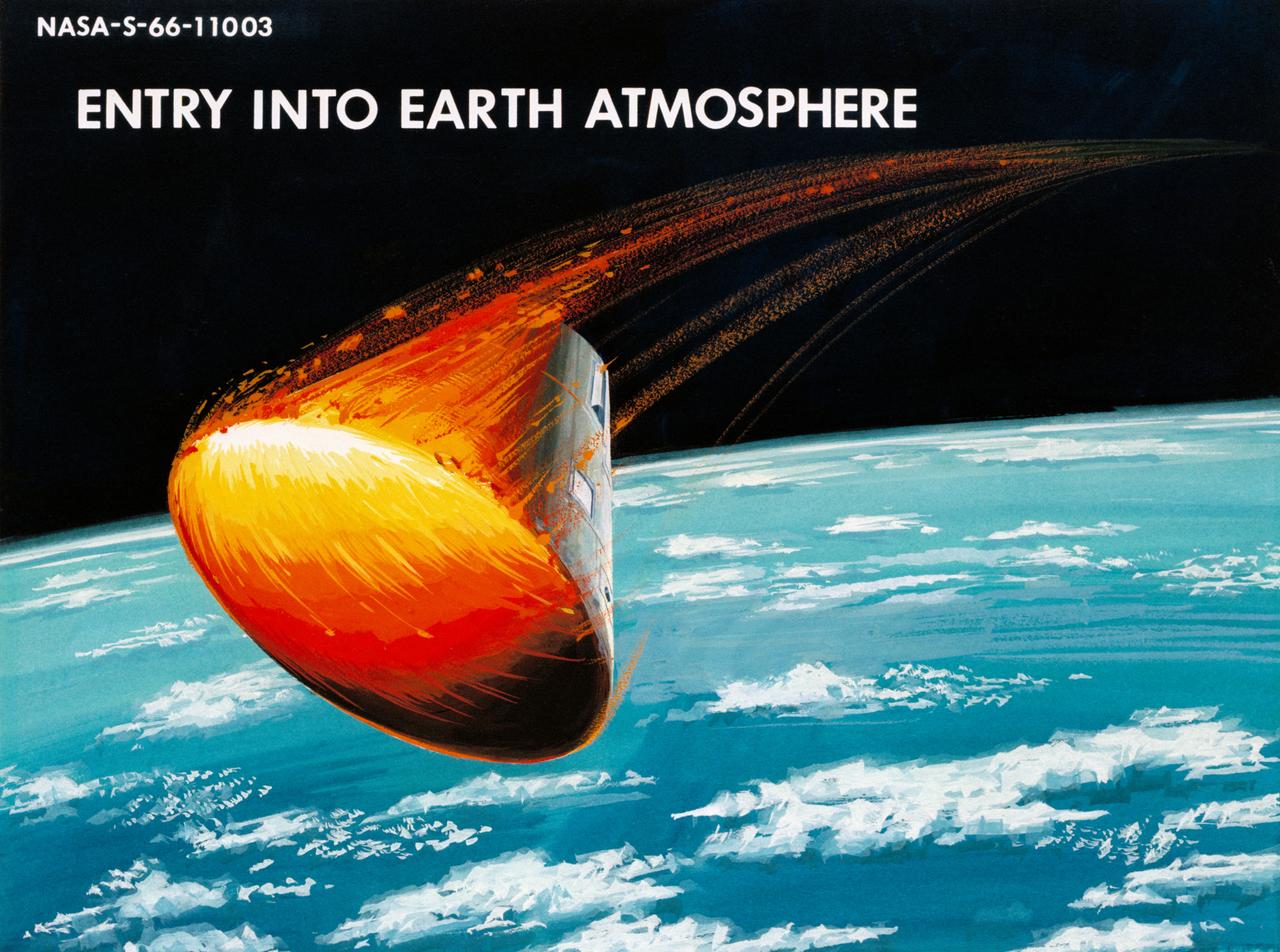
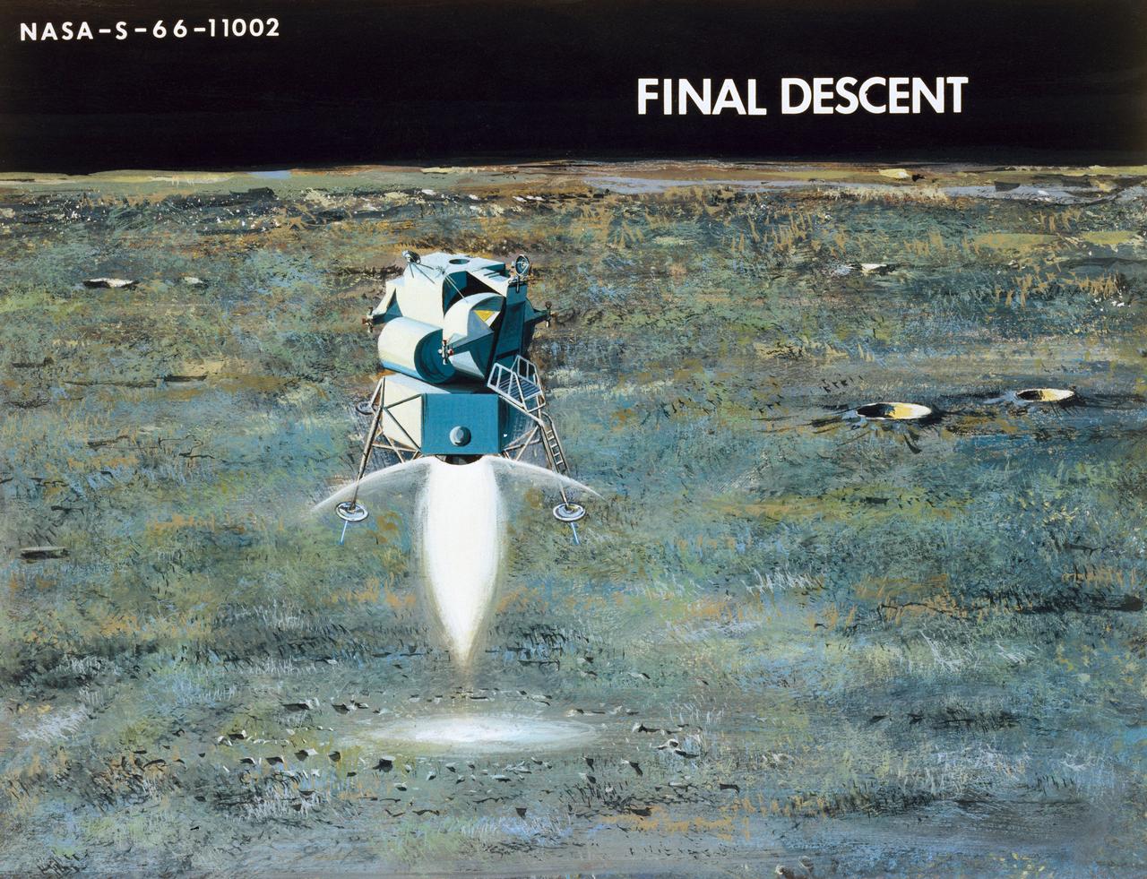
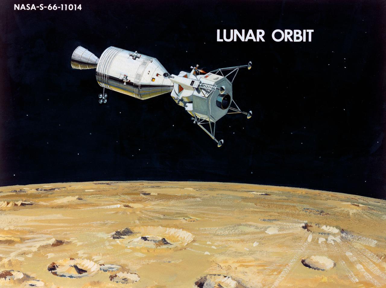
Artist Concepts, Apollo Mission: S66-10983: Ascent Stage Liftoff (S66-05094) S66-10984: Orientation During Ascent Phase (S66-05098) S66-10985: Midcourse Coast (S66-05113) S66-10986: Survey of Landing Site (S66-05117) S66-10987: Lunar Module (LM) Jettison (S66-05089) S66-10988: Trans-Earth Injection (S66-05090) S66-10989: Exploration on Lunar Surface Apollo Surface Lunar Exploration Experiment (ASLEP) S66-10990: Liftoff (S66-05125) S66-10991: Command Module (CM)-Service Module (SM) Separation (S66-05101 N/F) S66-10992: Touchdown on Lunar Surface (S66-05115) S66-10993: Transfer Orbit Insertion (S66-05111) S66-10994: Drogue Parachute Deployment S66-10995: S-IC Stage Separation S-II Stage Thrusting (S66-05099) S66-10996: Jettison Launch Escape System (S66-05114) S66-10997: Main Parachute Deployment (S66-05091) S66-10998: Mid-course correction (S66-05088) S66-10999: Lunar Orbit Insertion (S66-05086) S66-11000: Command Service Module (CSM)-LM Docked in LM Adapter-S-IVB (S66-06526) S66-11001: Docking and Separation of spacecraft from S-IVB (S66-05107) S66-11002: Final Descent (S66-05096) S66-11003: Entry into Earth Atmosphere (S66-05096) S66-11004: Deploy S/C LM Adapter-Separate CSM from LM-S-IVB (S66-06525 & 05105) S66-11005: Turnaround of CSM (S66-05104) S66-11006: S-II Stage Separation S-IVB Stage Thrusting (S66-05102) S66-11007: LM Ascent CSM Docked (S66-05100) S66-11008: Midcourse Correction SPS Mode (S66-05106) S66-11009: Earth Orbit Insertion of S-IVB & S/C (S66-05092) S66-11010: Trans-lunar Injection (S66-05116) S66-11011: LM Descent (S66-05110) S66-11012: S-IVB Stage Operations (S66-05112 N/F) S66-11013: Spacecraft Recovery (S66-05126) S66-11014: Lunar Orbit (S66-05103) S66-11015: CSM-LM Docking (S66-05095) S66-11016: Entry CM (S66-5109) S66-11017: Midcourse Corrections to Lunar Landing (S66-08486) S66-11018: Midcourse Corrections to Lunar Landing w/Overlay (S66-05083) S66-11019: Earth Launch Phase w/Overlay (S66-08485 & 05119) S66-11020: Earth Launch Phase (S66-08487 & S66-05084) S66-11022: Apollo Vehicles (S66-05127) S66-11024: Transfer to LM (S66-05082) S66-11025: Lunar Launch Phase S66-11027: Trans-earth Separation of C/M from S/M-C/M return to Earth (S66-05097) S66-11028: CSM-LM Separation, LM Descent to Moon (S66-05108) MSC, Houston, TX Also available in B&W 12/1965 - 06/1966
Artist Concepts, Apollo Mission: S66-10983: Ascent Stage Liftoff (S66-05094) S66-10984: Orientation During Ascent Phase (S66-05098) S66-10985: Midcourse Coast (S66-05113) S66-10986: Survey of Landing Site (S66-05117) S66-10987: Lunar Module (LM) Jettison (S66-05089) S66-10988: Trans-Earth Injection (S66-05090) S66-10989: Exploration on Lunar Surface Apollo Surface Lunar Exploration Experiment (ASLEP) S66-10990: Liftoff (S66-05125) S66-10991: Command Module (CM)-Service Module (SM) Separation (S66-05101 N/F) S66-10992: Touchdown on Lunar Surface (S66-05115) S66-10993: Transfer Orbit Insertion (S66-05111) S66-10994: Drogue Parachute Deployment S66-10995: S-IC Stage Separation S-II Stage Thrusting (S66-05099) S66-10996: Jettison Launch Escape System (S66-05114) S66-10997: Main Parachute Deployment (S66-05091) S66-10998: Mid-course correction (S66-05088) S66-10999: Lunar Orbit Insertion (S66-05086) S66-11000: Command Service Module (CSM)-LM Docked in LM Adapter-S-IVB (S66-06526) S66-11001: Docking and Separation of spacecraft from S-IVB (S66-05107) S66-11002: Final Descent (S66-05096) S66-11003: Entry into Earth Atmosphere (S66-05096) S66-11004: Deploy S/C LM Adapter-Separate CSM from LM-S-IVB (S66-06525 & 05105) S66-11005: Turnaround of CSM (S66-05104) S66-11006: S-II Stage Separation S-IVB Stage Thrusting (S66-05102) S66-11007: LM Ascent CSM Docked (S66-05100) S66-11008: Midcourse Correction SPS Mode (S66-05106) S66-11009: Earth Orbit Insertion of S-IVB & S/C (S66-05092) S66-11010: Trans-lunar Injection (S66-05116) S66-11011: LM Descent (S66-05110) S66-11012: S-IVB Stage Operations (S66-05112 N/F) S66-11013: Spacecraft Recovery (S66-05126) S66-11014: Lunar Orbit (S66-05103) S66-11015: CSM-LM Docking (S66-05095) S66-11016: Entry CM (S66-5109) S66-11017: Midcourse Corrections to Lunar Landing (S66-08486) S66-11018: Midcourse Corrections to Lunar Landing w/Overlay (S66-05083) S66-11019: Earth Launch Phase w/Overlay (S66-08485 & 05119) S66-11020: Earth Launch Phase (S66-08487 & S66-05084) S66-11022: Apollo Vehicles (S66-05127) S66-11024: Transfer to LM (S66-05082) S66-11025: Lunar Launch Phase S66-11027: Trans-earth Separation of C/M from S/M-C/M return to Earth (S66-05097) S66-11028: CSM-LM Separation, LM Descent to Moon (S66-05108) MSC, Houston, TX Also available in B&W 12/1965 - 06/1966
Artist Concepts, Apollo Mission: S66-10983: Ascent Stage Liftoff (S66-05094) S66-10984: Orientation During Ascent Phase (S66-05098) S66-10985: Midcourse Coast (S66-05113) S66-10986: Survey of Landing Site (S66-05117) S66-10987: Lunar Module (LM) Jettison (S66-05089) S66-10988: Trans-Earth Injection (S66-05090) S66-10989: Exploration on Lunar Surface Apollo Surface Lunar Exploration Experiment (ASLEP) S66-10990: Liftoff (S66-05125) S66-10991: Command Module (CM)-Service Module (SM) Separation (S66-05101 N/F) S66-10992: Touchdown on Lunar Surface (S66-05115) S66-10993: Transfer Orbit Insertion (S66-05111) S66-10994: Drogue Parachute Deployment S66-10995: S-IC Stage Separation S-II Stage Thrusting (S66-05099) S66-10996: Jettison Launch Escape System (S66-05114) S66-10997: Main Parachute Deployment (S66-05091) S66-10998: Mid-course correction (S66-05088) S66-10999: Lunar Orbit Insertion (S66-05086) S66-11000: Command Service Module (CSM)-LM Docked in LM Adapter-S-IVB (S66-06526) S66-11001: Docking and Separation of spacecraft from S-IVB (S66-05107) S66-11002: Final Descent (S66-05096) S66-11003: Entry into Earth Atmosphere (S66-05096) S66-11004: Deploy S/C LM Adapter-Separate CSM from LM-S-IVB (S66-06525 & 05105) S66-11005: Turnaround of CSM (S66-05104) S66-11006: S-II Stage Separation S-IVB Stage Thrusting (S66-05102) S66-11007: LM Ascent CSM Docked (S66-05100) S66-11008: Midcourse Correction SPS Mode (S66-05106) S66-11009: Earth Orbit Insertion of S-IVB & S/C (S66-05092) S66-11010: Trans-lunar Injection (S66-05116) S66-11011: LM Descent (S66-05110) S66-11012: S-IVB Stage Operations (S66-05112 N/F) S66-11013: Spacecraft Recovery (S66-05126) S66-11014: Lunar Orbit (S66-05103) S66-11015: CSM-LM Docking (S66-05095) S66-11016: Entry CM (S66-5109) S66-11017: Midcourse Corrections to Lunar Landing (S66-08486) S66-11018: Midcourse Corrections to Lunar Landing w/Overlay (S66-05083) S66-11019: Earth Launch Phase w/Overlay (S66-08485 & 05119) S66-11020: Earth Launch Phase (S66-08487 & S66-05084) S66-11022: Apollo Vehicles (S66-05127) S66-11024: Transfer to LM (S66-05082) S66-11025: Lunar Launch Phase S66-11027: Trans-earth Separation of C/M from S/M-C/M return to Earth (S66-05097) S66-11028: CSM-LM Separation, LM Descent to Moon (S66-05108) MSC, Houston, TX Also available in B&W 12/1965 - 06/1966
Artist Concepts, Apollo Mission: S66-10983: Ascent Stage Liftoff (S66-05094) S66-10984: Orientation During Ascent Phase (S66-05098) S66-10985: Midcourse Coast (S66-05113) S66-10986: Survey of Landing Site (S66-05117) S66-10987: Lunar Module (LM) Jettison (S66-05089) S66-10988: Trans-Earth Injection (S66-05090) S66-10989: Exploration on Lunar Surface Apollo Surface Lunar Exploration Experiment (ASLEP) S66-10990: Liftoff (S66-05125) S66-10991: Command Module (CM)-Service Module (SM) Separation (S66-05101 N/F) S66-10992: Touchdown on Lunar Surface (S66-05115) S66-10993: Transfer Orbit Insertion (S66-05111) S66-10994: Drogue Parachute Deployment S66-10995: S-IC Stage Separation S-II Stage Thrusting (S66-05099) S66-10996: Jettison Launch Escape System (S66-05114) S66-10997: Main Parachute Deployment (S66-05091) S66-10998: Mid-course correction (S66-05088) S66-10999: Lunar Orbit Insertion (S66-05086) S66-11000: Command Service Module (CSM)-LM Docked in LM Adapter-S-IVB (S66-06526) S66-11001: Docking and Separation of spacecraft from S-IVB (S66-05107) S66-11002: Final Descent (S66-05096) S66-11003: Entry into Earth Atmosphere (S66-05096) S66-11004: Deploy S/C LM Adapter-Separate CSM from LM-S-IVB (S66-06525 & 05105) S66-11005: Turnaround of CSM (S66-05104) S66-11006: S-II Stage Separation S-IVB Stage Thrusting (S66-05102) S66-11007: LM Ascent CSM Docked (S66-05100) S66-11008: Midcourse Correction SPS Mode (S66-05106) S66-11009: Earth Orbit Insertion of S-IVB & S/C (S66-05092) S66-11010: Trans-lunar Injection (S66-05116) S66-11011: LM Descent (S66-05110) S66-11012: S-IVB Stage Operations (S66-05112 N/F) S66-11013: Spacecraft Recovery (S66-05126) S66-11014: Lunar Orbit (S66-05103) S66-11015: CSM-LM Docking (S66-05095) S66-11016: Entry CM (S66-5109) S66-11017: Midcourse Corrections to Lunar Landing (S66-08486) S66-11018: Midcourse Corrections to Lunar Landing w/Overlay (S66-05083) S66-11019: Earth Launch Phase w/Overlay (S66-08485 & 05119) S66-11020: Earth Launch Phase (S66-08487 & S66-05084) S66-11022: Apollo Vehicles (S66-05127) S66-11024: Transfer to LM (S66-05082) S66-11025: Lunar Launch Phase S66-11027: Trans-earth Separation of C/M from S/M-C/M return to Earth (S66-05097) S66-11028: CSM-LM Separation, LM Descent to Moon (S66-05108) MSC, Houston, TX Also available in B&W 12/1965 - 06/1966
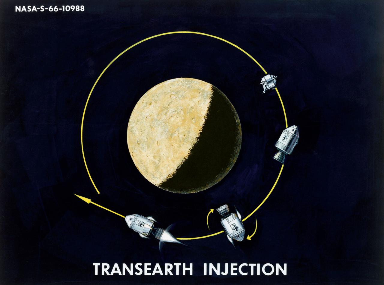
Artist Concepts, Apollo Mission: S66-10983: Ascent Stage Liftoff (S66-05094) S66-10984: Orientation During Ascent Phase (S66-05098) S66-10985: Midcourse Coast (S66-05113) S66-10986: Survey of Landing Site (S66-05117) S66-10987: Lunar Module (LM) Jettison (S66-05089) S66-10988: Trans-Earth Injection (S66-05090) S66-10989: Exploration on Lunar Surface Apollo Surface Lunar Exploration Experiment (ASLEP) S66-10990: Liftoff (S66-05125) S66-10991: Command Module (CM)-Service Module (SM) Separation (S66-05101 N/F) S66-10992: Touchdown on Lunar Surface (S66-05115) S66-10993: Transfer Orbit Insertion (S66-05111) S66-10994: Drogue Parachute Deployment S66-10995: S-IC Stage Separation S-II Stage Thrusting (S66-05099) S66-10996: Jettison Launch Escape System (S66-05114) S66-10997: Main Parachute Deployment (S66-05091) S66-10998: Mid-course correction (S66-05088) S66-10999: Lunar Orbit Insertion (S66-05086) S66-11000: Command Service Module (CSM)-LM Docked in LM Adapter-S-IVB (S66-06526) S66-11001: Docking and Separation of spacecraft from S-IVB (S66-05107) S66-11002: Final Descent (S66-05096) S66-11003: Entry into Earth Atmosphere (S66-05096) S66-11004: Deploy S/C LM Adapter-Separate CSM from LM-S-IVB (S66-06525 & 05105) S66-11005: Turnaround of CSM (S66-05104) S66-11006: S-II Stage Separation S-IVB Stage Thrusting (S66-05102) S66-11007: LM Ascent CSM Docked (S66-05100) S66-11008: Midcourse Correction SPS Mode (S66-05106) S66-11009: Earth Orbit Insertion of S-IVB & S/C (S66-05092) S66-11010: Trans-lunar Injection (S66-05116) S66-11011: LM Descent (S66-05110) S66-11012: S-IVB Stage Operations (S66-05112 N/F) S66-11013: Spacecraft Recovery (S66-05126) S66-11014: Lunar Orbit (S66-05103) S66-11015: CSM-LM Docking (S66-05095) S66-11016: Entry CM (S66-5109) S66-11017: Midcourse Corrections to Lunar Landing (S66-08486) S66-11018: Midcourse Corrections to Lunar Landing w/Overlay (S66-05083) S66-11019: Earth Launch Phase w/Overlay (S66-08485 & 05119) S66-11020: Earth Launch Phase (S66-08487 & S66-05084) S66-11022: Apollo Vehicles (S66-05127) S66-11024: Transfer to LM (S66-05082) S66-11025: Lunar Launch Phase S66-11027: Trans-earth Separation of C/M from S/M-C/M return to Earth (S66-05097) S66-11028: CSM-LM Separation, LM Descent to Moon (S66-05108) MSC, Houston, TX Also available in B&W 12/1965 - 06/1966
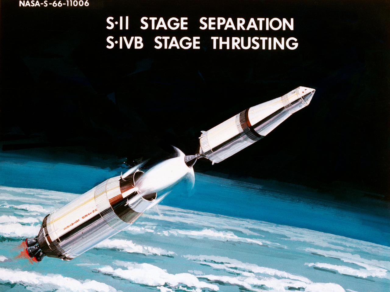
Artist Concepts, Apollo Mission: S66-10983: Ascent Stage Liftoff (S66-05094) S66-10984: Orientation During Ascent Phase (S66-05098) S66-10985: Midcourse Coast (S66-05113) S66-10986: Survey of Landing Site (S66-05117) S66-10987: Lunar Module (LM) Jettison (S66-05089) S66-10988: Trans-Earth Injection (S66-05090) S66-10989: Exploration on Lunar Surface Apollo Surface Lunar Exploration Experiment (ASLEP) S66-10990: Liftoff (S66-05125) S66-10991: Command Module (CM)-Service Module (SM) Separation (S66-05101 N/F) S66-10992: Touchdown on Lunar Surface (S66-05115) S66-10993: Transfer Orbit Insertion (S66-05111) S66-10994: Drogue Parachute Deployment S66-10995: S-IC Stage Separation S-II Stage Thrusting (S66-05099) S66-10996: Jettison Launch Escape System (S66-05114) S66-10997: Main Parachute Deployment (S66-05091) S66-10998: Mid-course correction (S66-05088) S66-10999: Lunar Orbit Insertion (S66-05086) S66-11000: Command Service Module (CSM)-LM Docked in LM Adapter-S-IVB (S66-06526) S66-11001: Docking and Separation of spacecraft from S-IVB (S66-05107) S66-11002: Final Descent (S66-05096) S66-11003: Entry into Earth Atmosphere (S66-05096) S66-11004: Deploy S/C LM Adapter-Separate CSM from LM-S-IVB (S66-06525 & 05105) S66-11005: Turnaround of CSM (S66-05104) S66-11006: S-II Stage Separation S-IVB Stage Thrusting (S66-05102) S66-11007: LM Ascent CSM Docked (S66-05100) S66-11008: Midcourse Correction SPS Mode (S66-05106) S66-11009: Earth Orbit Insertion of S-IVB & S/C (S66-05092) S66-11010: Trans-lunar Injection (S66-05116) S66-11011: LM Descent (S66-05110) S66-11012: S-IVB Stage Operations (S66-05112 N/F) S66-11013: Spacecraft Recovery (S66-05126) S66-11014: Lunar Orbit (S66-05103) S66-11015: CSM-LM Docking (S66-05095) S66-11016: Entry CM (S66-5109) S66-11017: Midcourse Corrections to Lunar Landing (S66-08486) S66-11018: Midcourse Corrections to Lunar Landing w/Overlay (S66-05083) S66-11019: Earth Launch Phase w/Overlay (S66-08485 & 05119) S66-11020: Earth Launch Phase (S66-08487 & S66-05084) S66-11022: Apollo Vehicles (S66-05127) S66-11024: Transfer to LM (S66-05082) S66-11025: Lunar Launch Phase S66-11027: Trans-earth Separation of C/M from S/M-C/M return to Earth (S66-05097) S66-11028: CSM-LM Separation, LM Descent to Moon (S66-05108) MSC, Houston, TX Also available in B&W 12/1965 - 06/1966

Artist Concepts, Apollo Mission: S66-10983: Ascent Stage Liftoff (S66-05094) S66-10984: Orientation During Ascent Phase (S66-05098) S66-10985: Midcourse Coast (S66-05113) S66-10986: Survey of Landing Site (S66-05117) S66-10987: Lunar Module (LM) Jettison (S66-05089) S66-10988: Trans-Earth Injection (S66-05090) S66-10989: Exploration on Lunar Surface Apollo Surface Lunar Exploration Experiment (ASLEP) S66-10990: Liftoff (S66-05125) S66-10991: Command Module (CM)-Service Module (SM) Separation (S66-05101 N/F) S66-10992: Touchdown on Lunar Surface (S66-05115) S66-10993: Transfer Orbit Insertion (S66-05111) S66-10994: Drogue Parachute Deployment S66-10995: S-IC Stage Separation S-II Stage Thrusting (S66-05099) S66-10996: Jettison Launch Escape System (S66-05114) S66-10997: Main Parachute Deployment (S66-05091) S66-10998: Mid-course correction (S66-05088) S66-10999: Lunar Orbit Insertion (S66-05086) S66-11000: Command Service Module (CSM)-LM Docked in LM Adapter-S-IVB (S66-06526) S66-11001: Docking and Separation of spacecraft from S-IVB (S66-05107) S66-11002: Final Descent (S66-05096) S66-11003: Entry into Earth Atmosphere (S66-05096) S66-11004: Deploy S/C LM Adapter-Separate CSM from LM-S-IVB (S66-06525 & 05105) S66-11005: Turnaround of CSM (S66-05104) S66-11006: S-II Stage Separation S-IVB Stage Thrusting (S66-05102) S66-11007: LM Ascent CSM Docked (S66-05100) S66-11008: Midcourse Correction SPS Mode (S66-05106) S66-11009: Earth Orbit Insertion of S-IVB & S/C (S66-05092) S66-11010: Trans-lunar Injection (S66-05116) S66-11011: LM Descent (S66-05110) S66-11012: S-IVB Stage Operations (S66-05112 N/F) S66-11013: Spacecraft Recovery (S66-05126) S66-11014: Lunar Orbit (S66-05103) S66-11015: CSM-LM Docking (S66-05095) S66-11016: Entry CM (S66-5109) S66-11017: Midcourse Corrections to Lunar Landing (S66-08486) S66-11018: Midcourse Corrections to Lunar Landing w/Overlay (S66-05083) S66-11019: Earth Launch Phase w/Overlay (S66-08485 & 05119) S66-11020: Earth Launch Phase (S66-08487 & S66-05084) S66-11022: Apollo Vehicles (S66-05127) S66-11024: Transfer to LM (S66-05082) S66-11025: Lunar Launch Phase S66-11027: Trans-earth Separation of C/M from S/M-C/M return to Earth (S66-05097) S66-11028: CSM-LM Separation, LM Descent to Moon (S66-05108) MSC, Houston, TX Also available in B&W 12/1965 - 06/1966