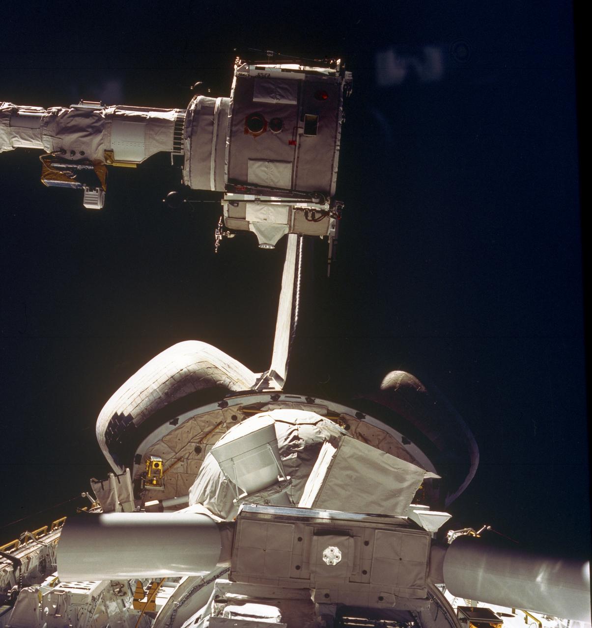
The Icing Research Tunnel (IRT) is the longest running, icing facility in the world and has been in operation since 1944. Most ice protection technologies in use today were largely developed at this facility. In this facility, natural icing conditions, such as the clouds being created here, are produced to test the effects of icing conditions on aircraft components such as wings tails and engine inlets.
Mechanical Test Engineer in the Icing Research Tunnel, IRT Co...
Common Research Model, CRM Full Chord and Midspan Test in the Icing Research Tunnel, IRT
CRM Full Chord and Midspan Test Documentation Photos Icing Research Tunnel
Emily Timko, featured in a Faces of NASA article, poses in the IRT (Icing Research Tunnel) where she works as a “cloud engineer”.  She is a Mechanical Test Engineer and works to create unique water spray conditions that simulate icing clouds in the natural aircraft flight environment.  Shown in the photo is a portion of the fan drive motor and fan blades that together drive the air through the wind tunnel.
Faces of NASA photograph of Emily Timko in the IRT (Icing Reach
Model in the Icing Research Tunnel, IRT
GRC-2013-C-01198
Pictured is a model to study the ice collection on struts in jet engines during flight. Researchers inspect the ice after the model encounters a simulated icing cloud during testing.  Super cooled water created from the icing cloud that flows though the wind tunnel.  The super cooled water forms ice on contact with the test model.  Researchers then inspect the ice formation before laser scanning of the ice formation for further research and analysis.
SIDRM II Documentation Photos at the Icing Research Tunnel (IRT)
INSTRUMENTATION COMPARISON HARDWARE IN ICING RESEARCH TUNNEL IRT
GRC-2000-C-01497
IMPINGEMENT TEST IN ICING RESEARCH TUNNEL IRT
GRC-2001-C-01460
Icing Research Tunnel (IRT) "AB Corner" Rehabilitation
GRC-2007-C-00622
IMPINGEMENT TEST IN ICING RESEARCH TUNNEL IRT
GRC-2001-C-01469
IRT - ICING RESEARCH TUNNEL WAKE SURVEY PROBE
GRC-2000-C-00763
Icing Research Tunnel (IRT) "AB Corner" Rehabilitation
GRC-2007-C-00620
1999 CONSTRUCTION OF FACILITY  ICING RESEARCH TUNNEL IRT HEAT EXCHANGER REPLACEMENT
GRC-1999-C-02440
THERMAL CODE I TEST HARDWARE IN ICING RESEARCH TUNNEL IRT
GRC-1996-C-02211
Common Research Model, CRM, in the Icing Research Tunnel, IRT
GRC-2015-C-01633
Isokinetic and Multi Wire Probes in the Icing Research Tunnel, IRT, Test Section
GRC-2013-C-02990
THERMAL CODE I TEST HARDWARE IN ICING RESEARCH TUNNEL IRT
GRC-1996-C-02214
ICING RESEARCH TUNNEL IRT FORCE BALANCE CALIBRATION HARDWARE
GRC-2000-C-01578
Common Research Model, CRM, in the Icing Research Tunnel, IRT
GRC-2015-C-01618
WICHITA STATE UNIVERSITY / ICING RESEARCH TUNNEL IRT DYE TEAM
GRC-1999-C-00431
1999 CONSTRUCTION OF FACILITY  ICING RESEARCH TUNNEL IRT HEAT EXCHANGER REPLACEMENT
GRC-2000-C-00138
Icing Research Tunnel (IRT) Expansion Addition Construction Documentation
GRC-2010-C-03338
Common Research Model, CRM, in the Icing Research Tunnel, IRT, Installation of Test Hardware
GRC-2015-C-00856
Construction of the Icing Research Tunnel, IRT, Refrigeration Plant-Newly Installed Heat Exchanger
GRC-2011-C-03450
Technicians spray steam to help scrape off ice at the Icing Research Tunnel. The technicians need all the help they can get in sub-zero temperatures. Photo Credit: (NASA/Jordan Salkin)
Deformed Skin Adhesion Test Documentation Photos at the Icing Research Tunnel (IRT)
Emily Timko, featured in a Faces of NASA article, poses in the IRT (Icing Research Tunnel) where she works as a “cloud engineer”.  She is a Mechanical Test Engineer and works to create unique water spray conditions that simulate icing clouds in the natural aircraft flight environment.  Shown in the photo is a test article of a rotating propeller configuration that the IRT researchers are investigating ice accretion with.
Faces of NASA photograph of Emily Timko in the Icing Research Tu
Panorama of the IRT engineering and ice cloud calibration team in the control room.  Shown on the left are the data and system engineers.  In the center with their backs to the camera are the wind tunnel operators who control the wind speed and super cooled water flow.  In the center right of the photo is the video recording system and the test engineers.  On the right side the test section can be see though the wind and the TV screen shows the pray bars that create the icing cloud.
GRC-2023-C-02727
This STS-51F mission onboard Photograph shows some of the Spacelab-2 instruments in the cargo bay of the Orbiter Challenger. The Plasma Diagnostics Package (PDP). shown at the end of the Remote Manipulator System (RMS), used instruments on a subsatellite to study natural plasma processes, orbiter-induced plasma processes, and beam plasma physics. Fourteen instruments were mounted on the PDP for measurements of various plasma characteristics. The X-ray Telescope (XRT), is at the front. The goal of this investigation was to image and examine the X-ray emissions from clusters of galaxies in order to study the mechanisms that cause high-temperature emissions and to determine the weight of galactic clusters. The Small Helium-Cooled Infrared Telescope (IRT) is at the right behind the XRT. The objective of this investigation was to measure and map diffused and discrete infrared astronomical sources while evaluating the Space Shuttle as a platform for infrared astronomy. At the same time, a new large superfluid helium dewar system for cooling the telescope was evaluated. The egg-shaped Cosmic Ray Nuclei experiment (CRNE) is shown at the rear. This investigation was to study the composition of high-energy cosmic rays by using a large instrument exposed to space for a considerable period of time. Spacelab-2 (STS-51F, 19th Shuttle mission) was launched aboard the Space Shuttle Orbiter Challenger on July 29, 1985.
Spacelab
Curtis Flack (left) and Paul von Hardenberg (right) inspect the ice formation on the spinner of an Advanced Air Mobility proprotor model tested in the Icing Research Tunnel. The data from the test will be used by icing researchers to better understand the risks of icing on electric vertical takeoff and landing vehicles which will assist with the design and certification of new aircraft.
AAM Rotor Icing Evaluation Studies (AIRES) I Test Documentation Photos at the Icing Research Tunnel (IRT)
An AH-64 (Apache) Longbow fire control full size radar photographed during icing tests in the Icing Research wind tunnel.  Built at the end of World War II, the Icing Research Tunnel is the oldest and largest refrigerated icing wind tunnel in the world. It can produce winds that travel up to 395 miles per hour and reach temperatures as low as -30 degrees Fahrenheit. The facility simulates ice formation during flight by spraying a cloud of super-cooled water droplets onto an aircraft component or model.
LONG BOW MODEL DURING ICING TEST
Ice built up on a test article at the at the Icing Research Tunnel as researchers study the icing physics that occur when aircraft fly through freezing weather conditions.
SIDRM Test at Icing Research Tunnel
Significant ice build-up on the Simulated Inter-compressor Duct Research Model (SIDRM) at the Icing Research Tunnel. Photo Credit: (NASA/Jordan Salkin)
SIDRM Ice Build-up
Lead researcher Tadas Bartkus poses after a run of his test with significant ice build-up on the Simulated Inter-compressor Duct Research Model (SIDRM) at the Icing Research Tunnel. Photo Credit: (NASA/Jordan Salkin)
Tadas Bartkus posing with SIDRM Ice Build-up
CRM Full Chord Installation and Test Documentation Photos, Icing Research Tunnel
A technician is shown preparing the research model for its next test condition by removing ice accretion. Photo Credit: (NASA/Jordan Salkin)
TTBW Wing-Truss Junction Model at the Icing Research Tunnel
CRM Full Chord Installation and Test Documentation Photos, Icing Research Tunnel
Zaid Sabri and Thomas Ozoroski, Icing Researchers, are shown documenting ice accretion on the leading edge of the next-generation Transonic Truss-Braced Wing design at NASA Glenn's Icing Research Center. This critical research will help understand icing effects for future, high-lift, ultra-efficient aircraft. Photo Credit: (NASA/Jordan Salkin)
TTBW Wing-Truss Junction Model at the Icing Research Tunnel
Ice accretion is shown on the leading edge of the next-generation Transonic Truss-Braced Wing design at NASA Glenn's Icing Research Center. This critical research will help understand icing effects for future, high-lift, ultra-efficient aircraft. Photo Credit: (NASA/Jordan Salkin)
TTBW Wing-Truss Junction Model at the Icing Research Tunnel
Test engineers clean the ice cloud detection probe in the Icing Research Tunnel in between test runs.  Steam is used to melt the accumulated ice on the detection probe.  The test engineers need to wear goggles to protect them from the laser light that the probe emits.  The laser detects water content and ice particles in the cloud that the wind tunnel produces.  This process is done to calibrate the tunnel for research by characterizing the cloud flow.
GRC-2023-C-11746
Thomas Ozoroski, an Icing Researcher, is shown documenting ice accretion on the leading edge of the next-generation Transonic Truss-Braced Wing design at NASA Glenn's Icing Research Center. This critical research will help understand icing effects for future, high-lift, ultra-efficient aircraft. Photo Credit: (NASA/Jordan Salkin)
TTBW Wing-Truss Junction Model at the Icing Research Tunnel
CRM Full Chord Installation and Test Documentation Photos, Icing Research Tunnel