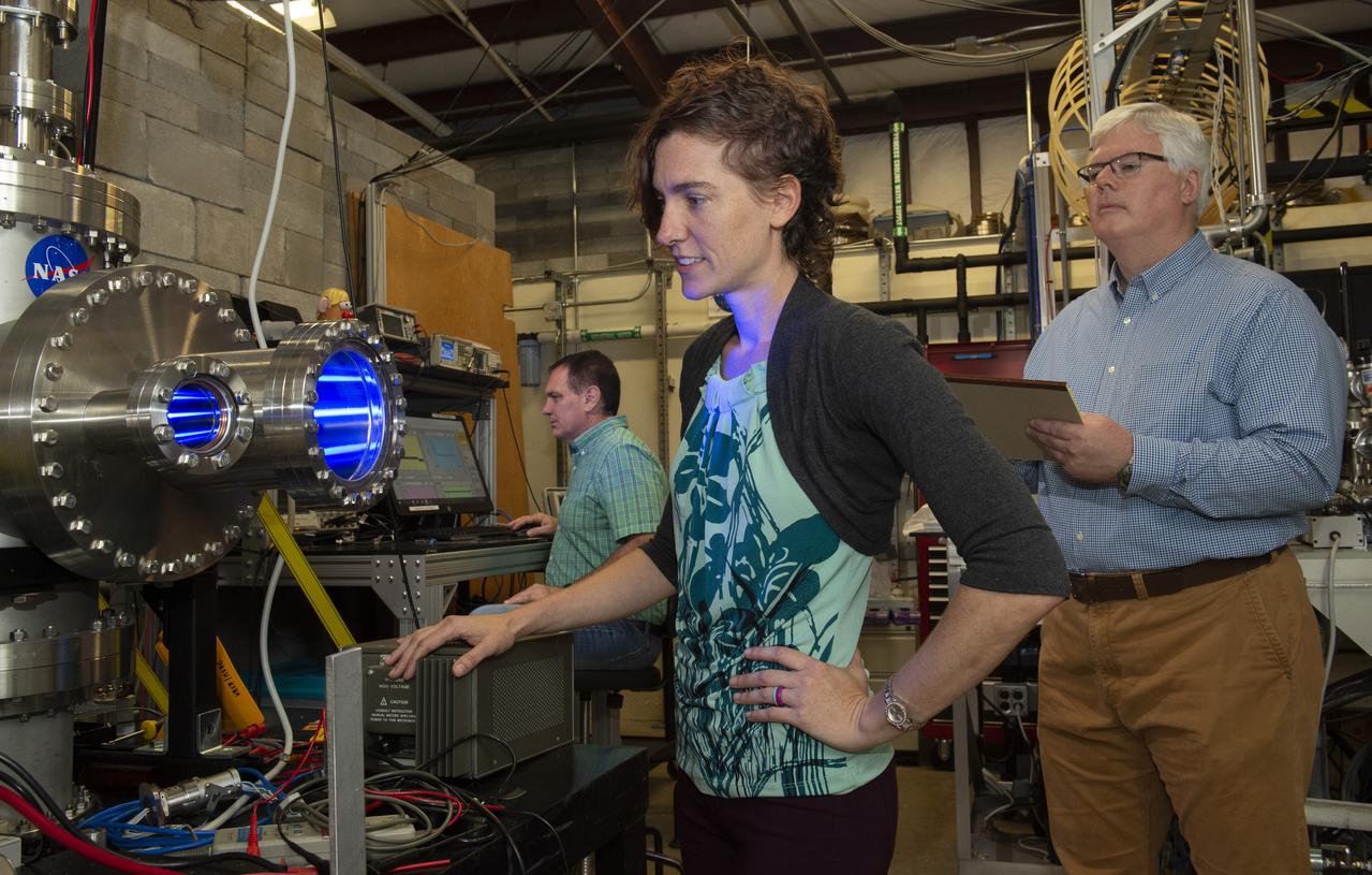
International Space Station (ISS) Remote Power Control Module (RPCM) Hot-mate/De-mate Assessment Dr. Erin Hayward , Mr. Todd Schneider, Mr. Jason Vaughn
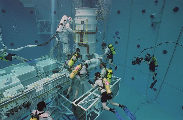
Astronaut Joe Lindquist and Kate Rupley conduct underwater testing on the International Space Station's power module in Marshall's Neutral Buoyancy Simulator (NBS).
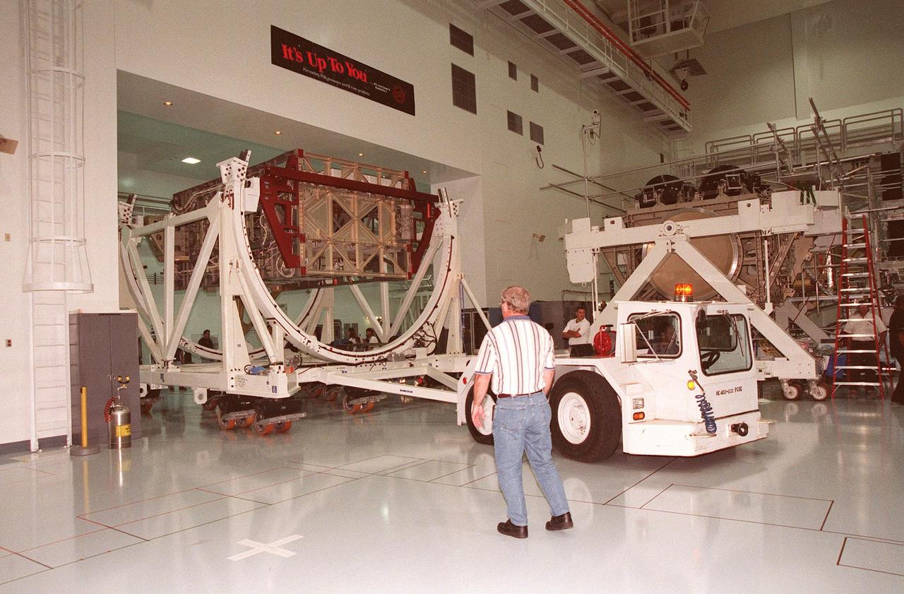
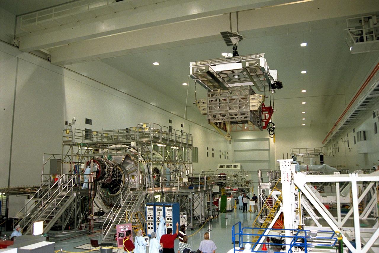
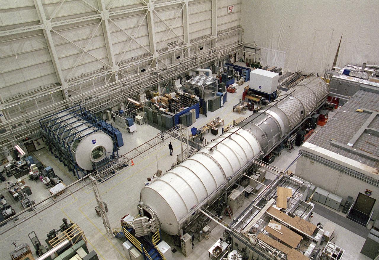
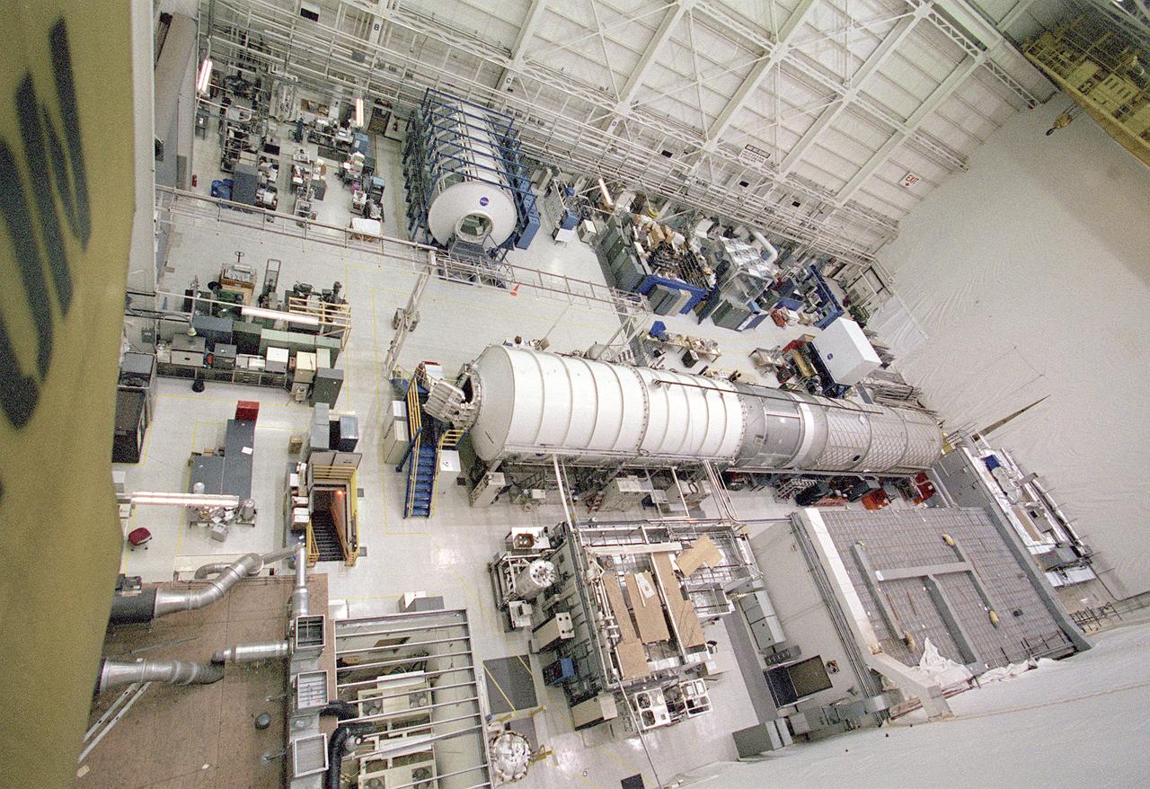
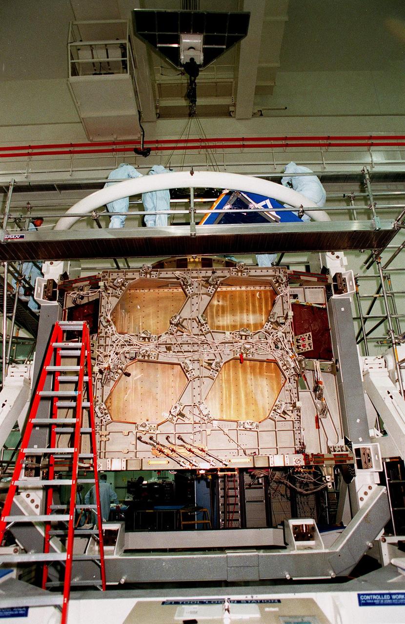
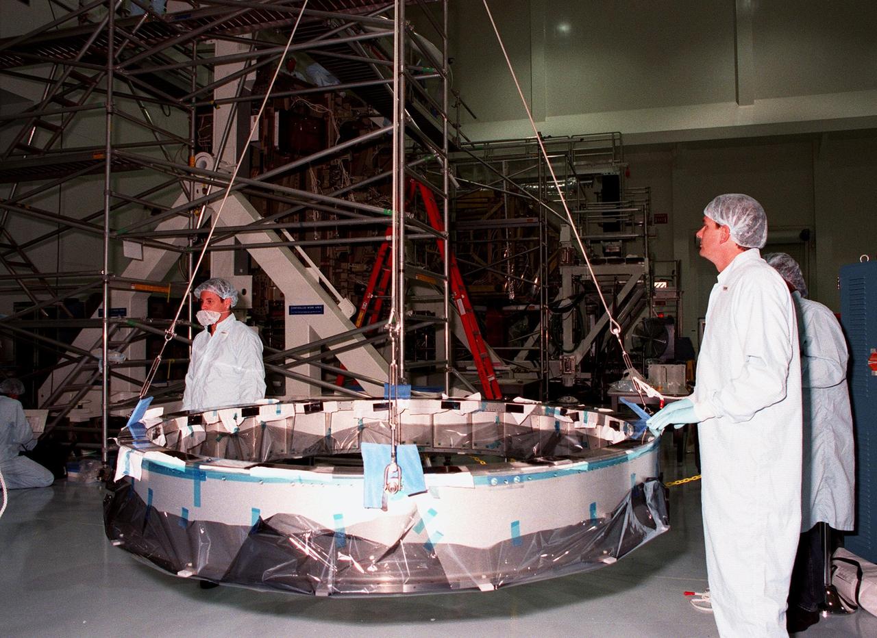
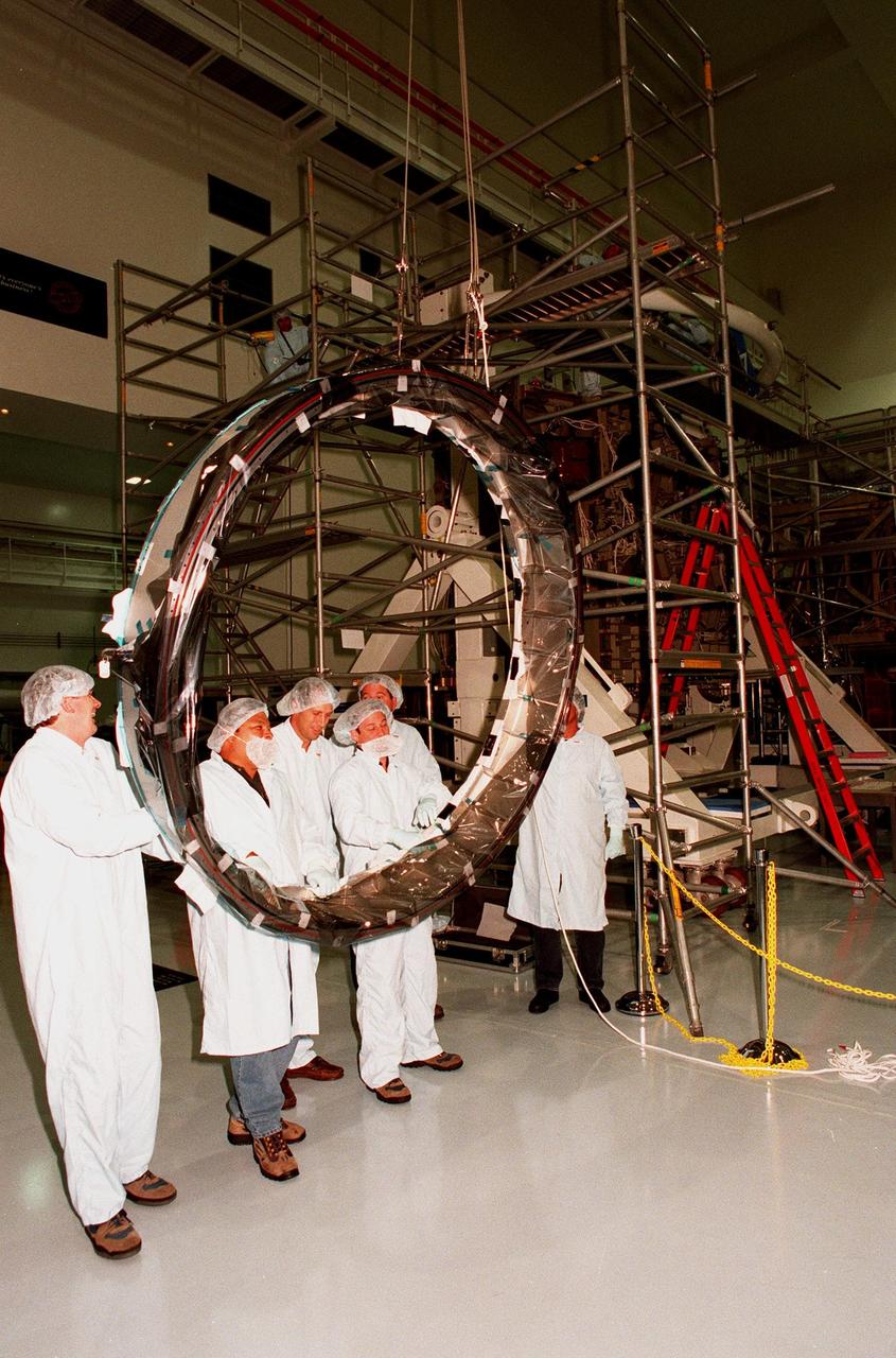
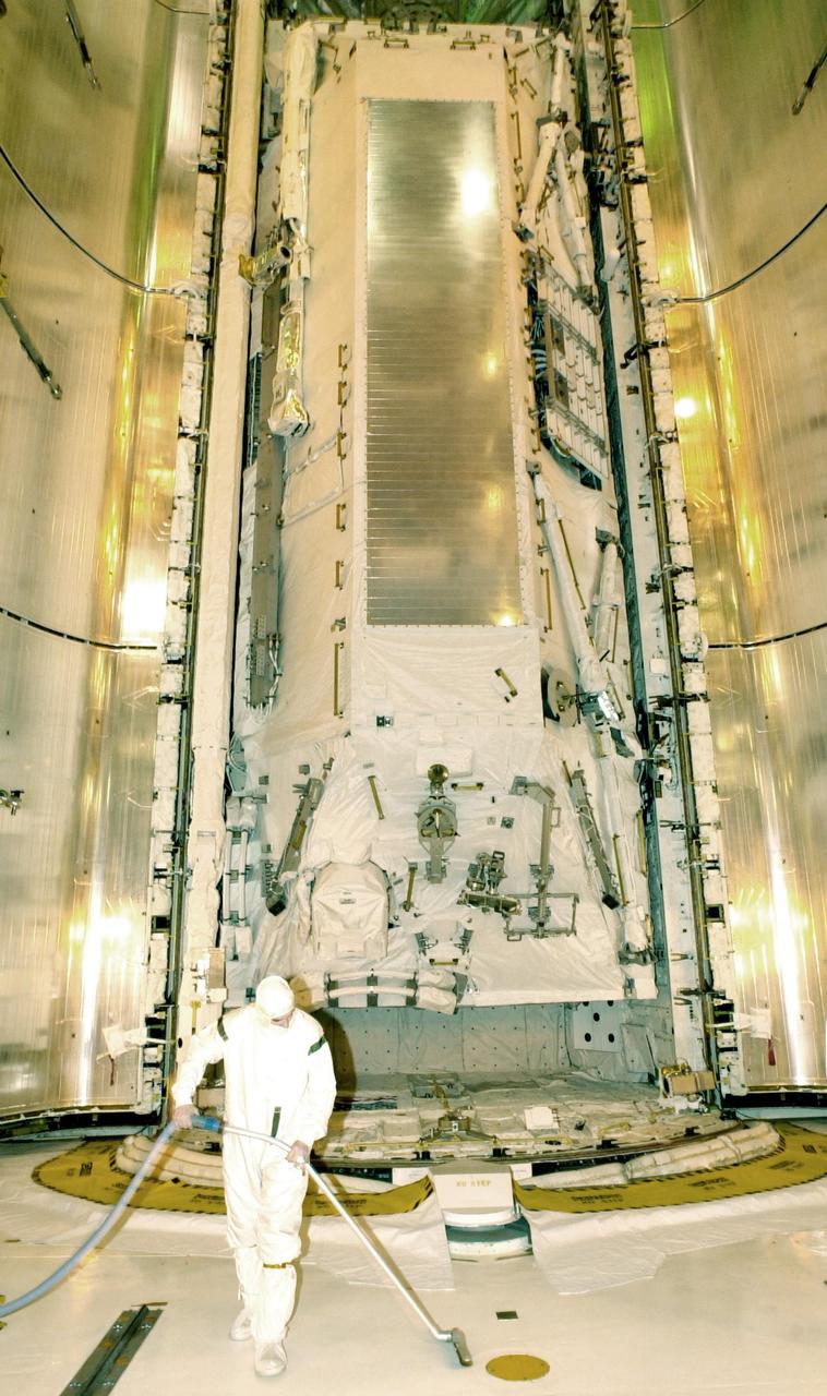
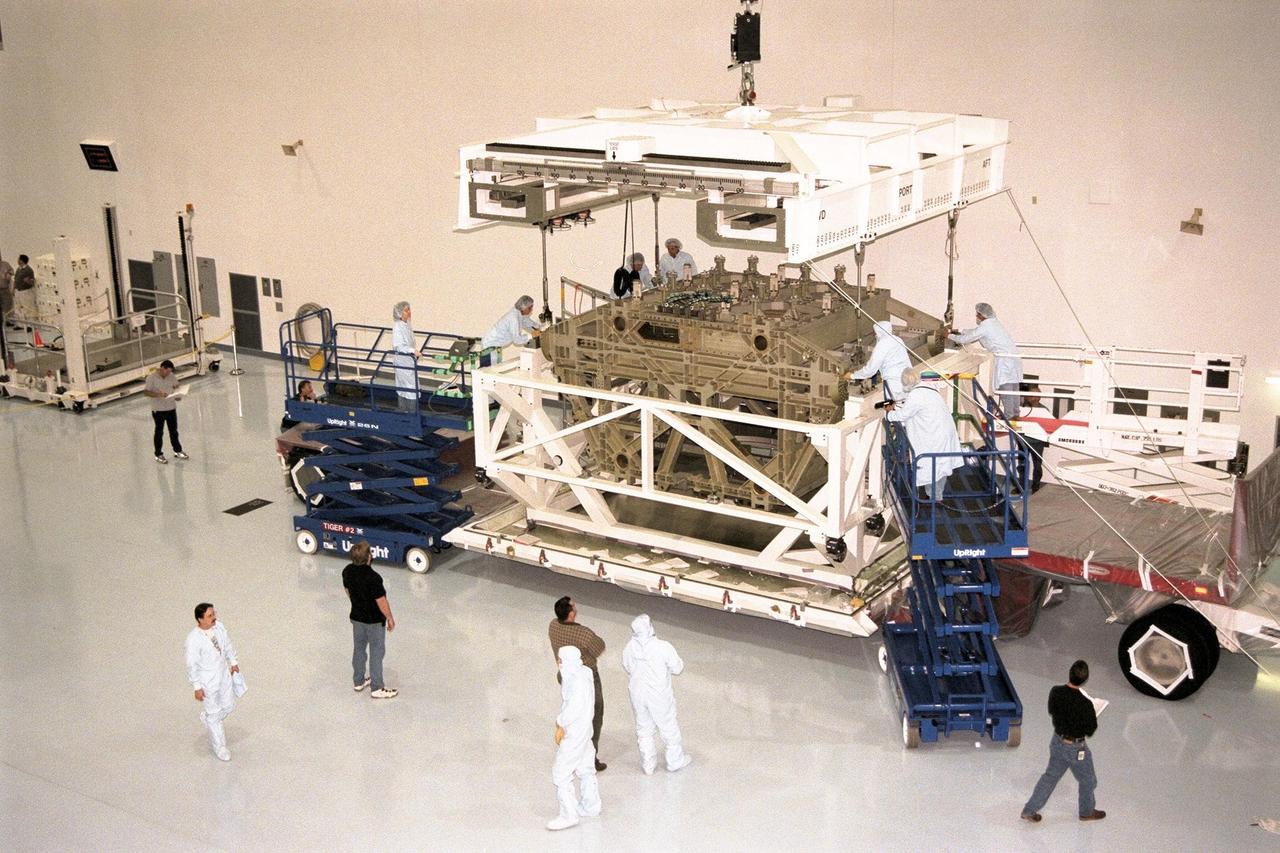
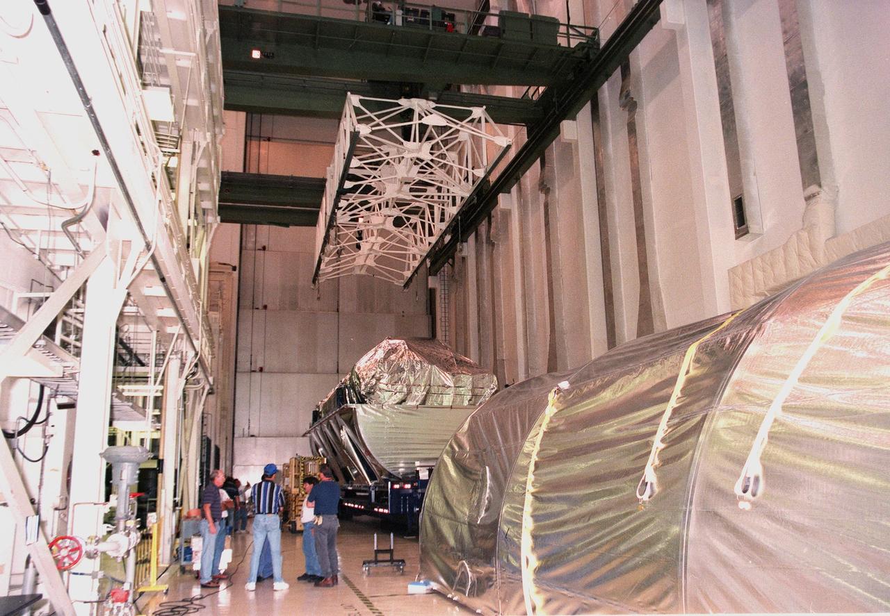
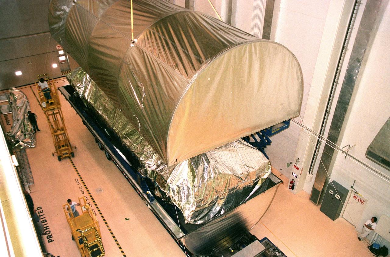
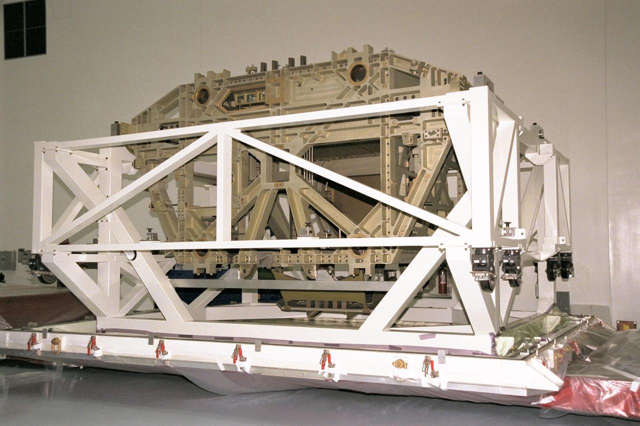
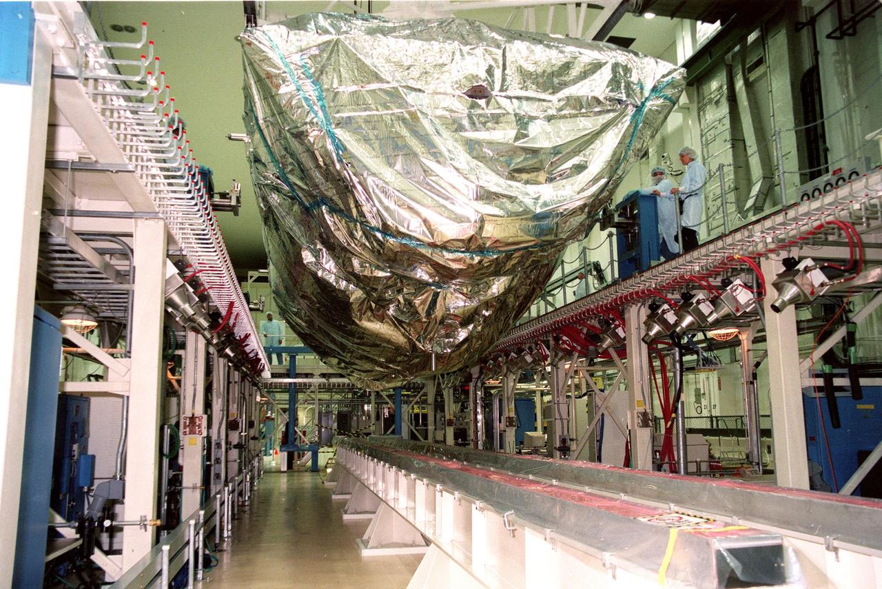
An Integrated Equipment Assembly (IEA) is moved from the low bay into the high bay at the Space Station Processing Facility at KSC. The IEA, a large truss segment of the International Space Station (ISS), is one of four power modules to be used on the ISS. The modules contain batteries for the ISS solar panels and power for the life support systems and experiments that will be conducted. This first IEA will fly on the Space Shuttle Endeavour as part of STS-97, scheduled to launch August 5, 1999
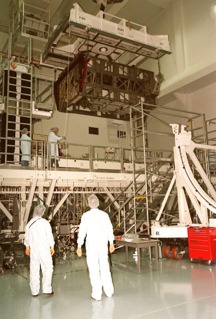
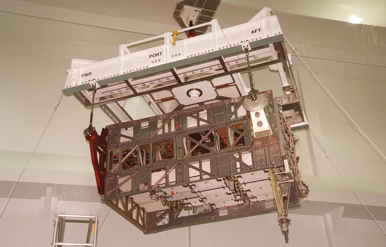
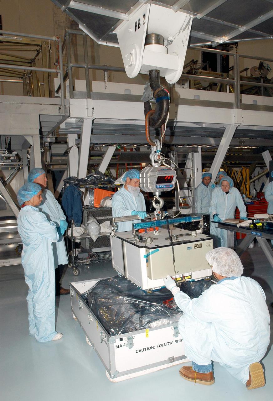
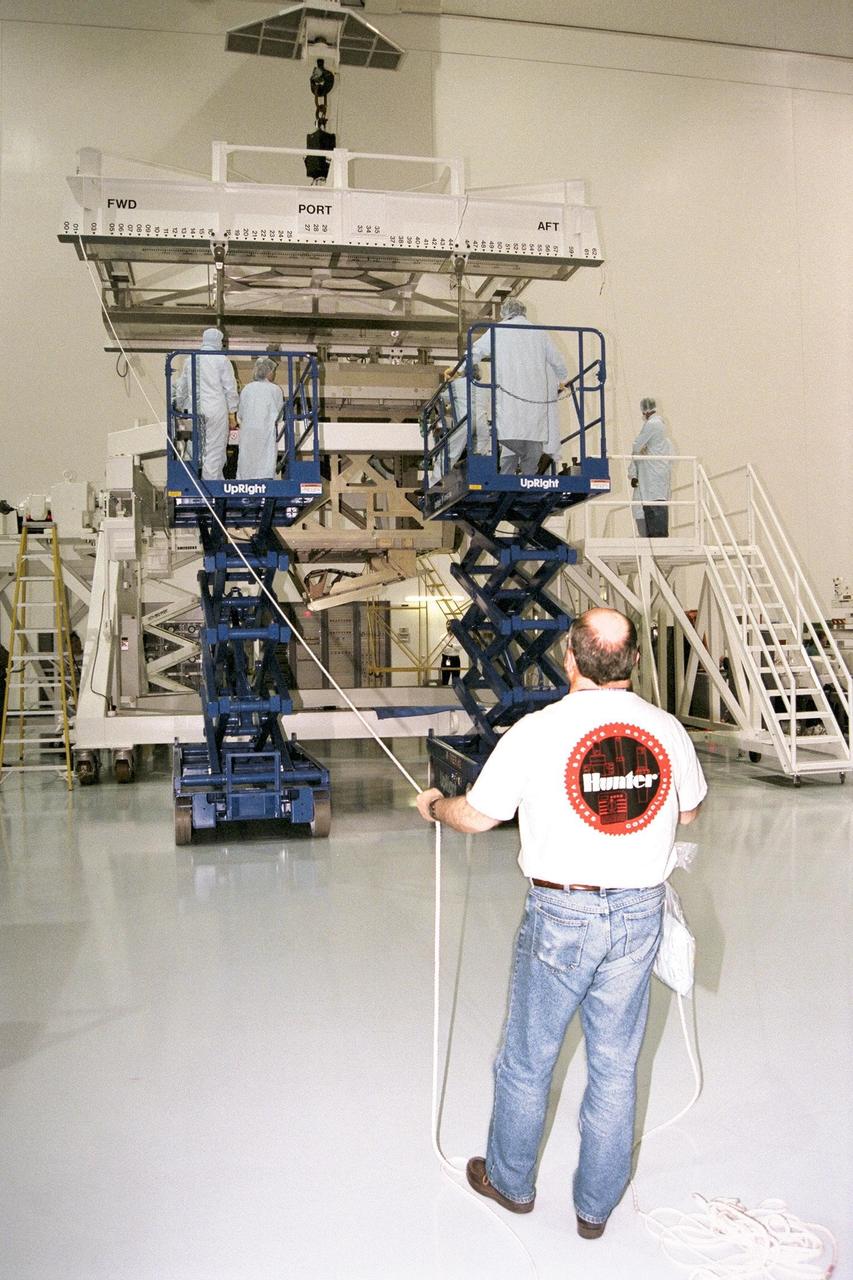
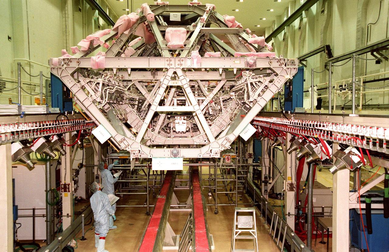
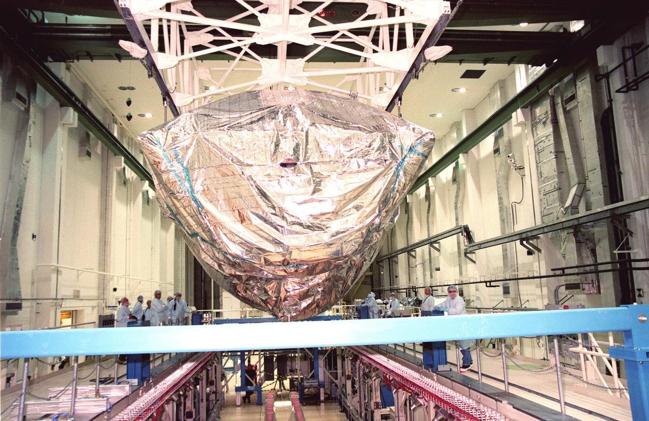
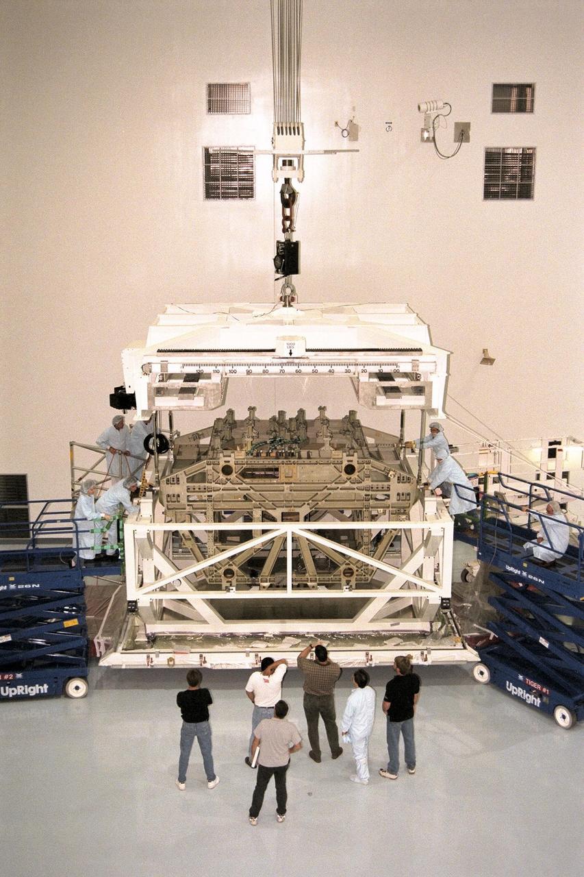
Technicians in the Space Station Processing Facility at KSC prepare to lower an Integrated Equipment Assembly (IEA) onto a work stand. The IEA, a large truss segment of the International Space Station (ISS), is one of four power modules to be used on the International Space Station. The modules contain batteries for the ISS solar panels and power for the life support systems and experiments that will be conducted. This first IEA will fly on the Space Shuttle Endeavour as part of STS-97, scheduled to launch August 5, 1999
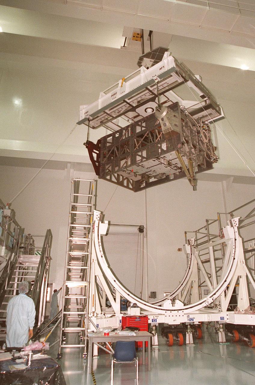
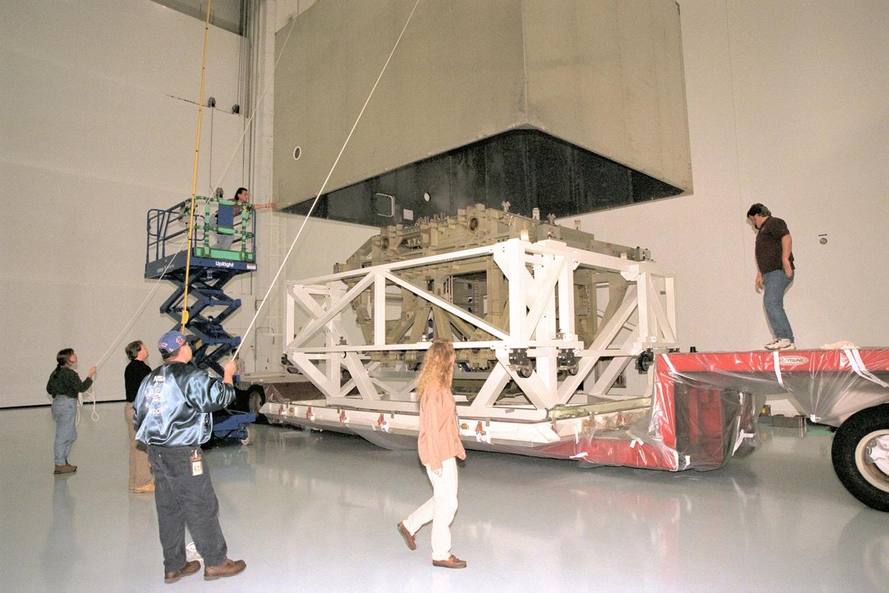
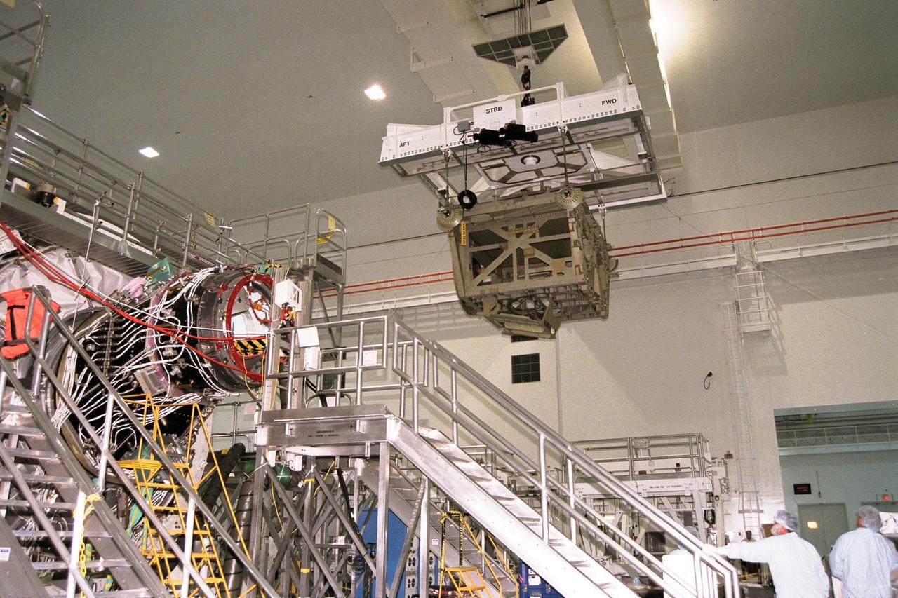
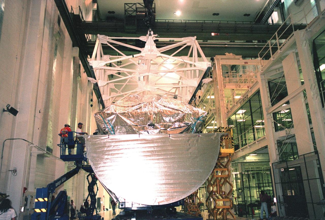
An Integrated Equipment Assembly (IEA) is lifted from a rotation stand in the Space Station Processing Facility at KSC to be placed on a work stand. The IEA, a large truss segment of the International Space Station (ISS), is one of four power modules to be used on the International Space Station. The modules contain batteries for the ISS solar panels and power for the life support systems and experiments that will be conducted. This first IEA will fly on the Space Shuttle Endeavour as part of STS-97, scheduled to launch August 5, 1999
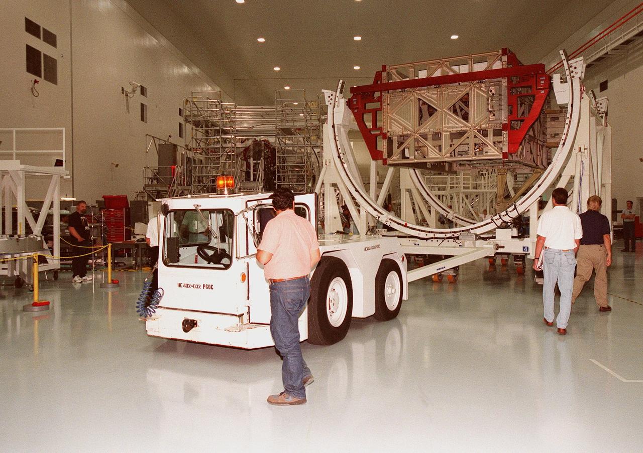
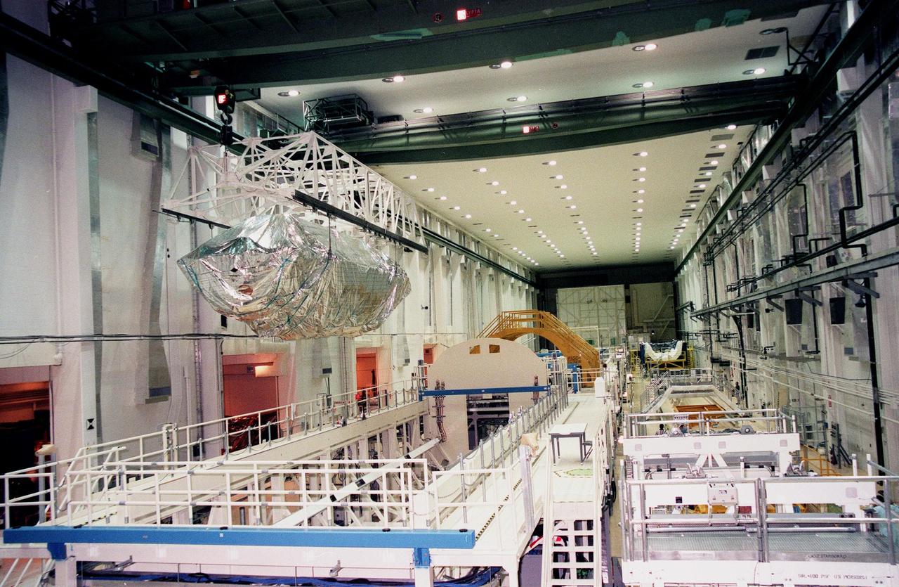
An Integrated Equipment Assembly (IEA) is moved into the center of the Space Station Processing Facility clean room at KSC for transition to the high bay. The IEA, a large truss segment of the International Space Station (ISS), is one of four power modules to be used on the International Space Station. The modules contain batteries for the ISS solar panels and power for the life support systems and experiments that will be conducted. This first IEA will fly on the Space Shuttle Endeavour as part of STS-97, scheduled to launch August 5, 1999
An Integrated Equipment Assembly (IEA) is suspended in air after being lifted from a rotation stand in the Space Station Processing Facility at KSC in order to be moved to a work stand. The IEA, a large truss segment of the International Space Station (ISS), is one of four power modules to be used on the International Space Station. The modules contain batteries for the ISS solar panels and power for the life support systems and experiments that will be conducted. This first IEA will fly on the Space Shuttle Endeavour as part of STS-97, scheduled to launch August 5, 1999
Technicians carefully lower an Integrated Equipment Assembly (IEA) onto a work stand in the Space Station Processing Facility at KSC . The IEA, a large truss segment of the International Space Station (ISS), is one of four power modules to be used on the International Space Station. The modules contain batteries for the ISS solar panels and power for the life support systems and experiments that will be conducted. This first IEA will fly on the Space Shuttle Endeavour as part of STS-97, scheduled to launch August 5, 1999
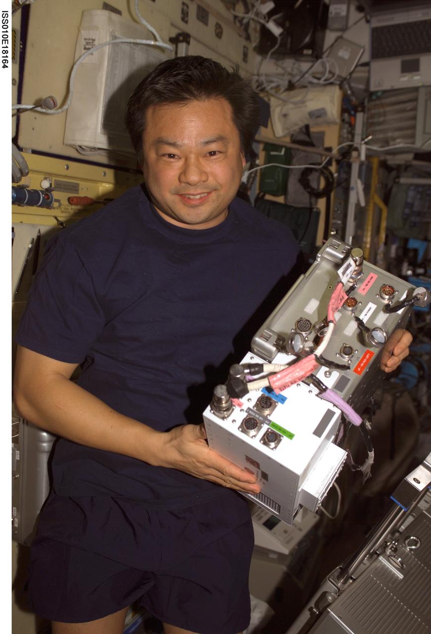
ISS010-E-18164 (17 February 2005) --- Astronaut Leroy Chiao, Expedition 10 commander and NASA ISS science officer, holds an Electronic Box Assembly, and Violation Isolation and Stabilization (VIS) Controller Assembly, which is part of the Treadmill Vibration Isolation System (TVIS) in the Zvezda Service Module of the International Space Station (ISS). Also in view is a VIS/TM data cable and VIS/TM power cable. This box receives power and distributes it between the treadmill and the VIS subassemblies.
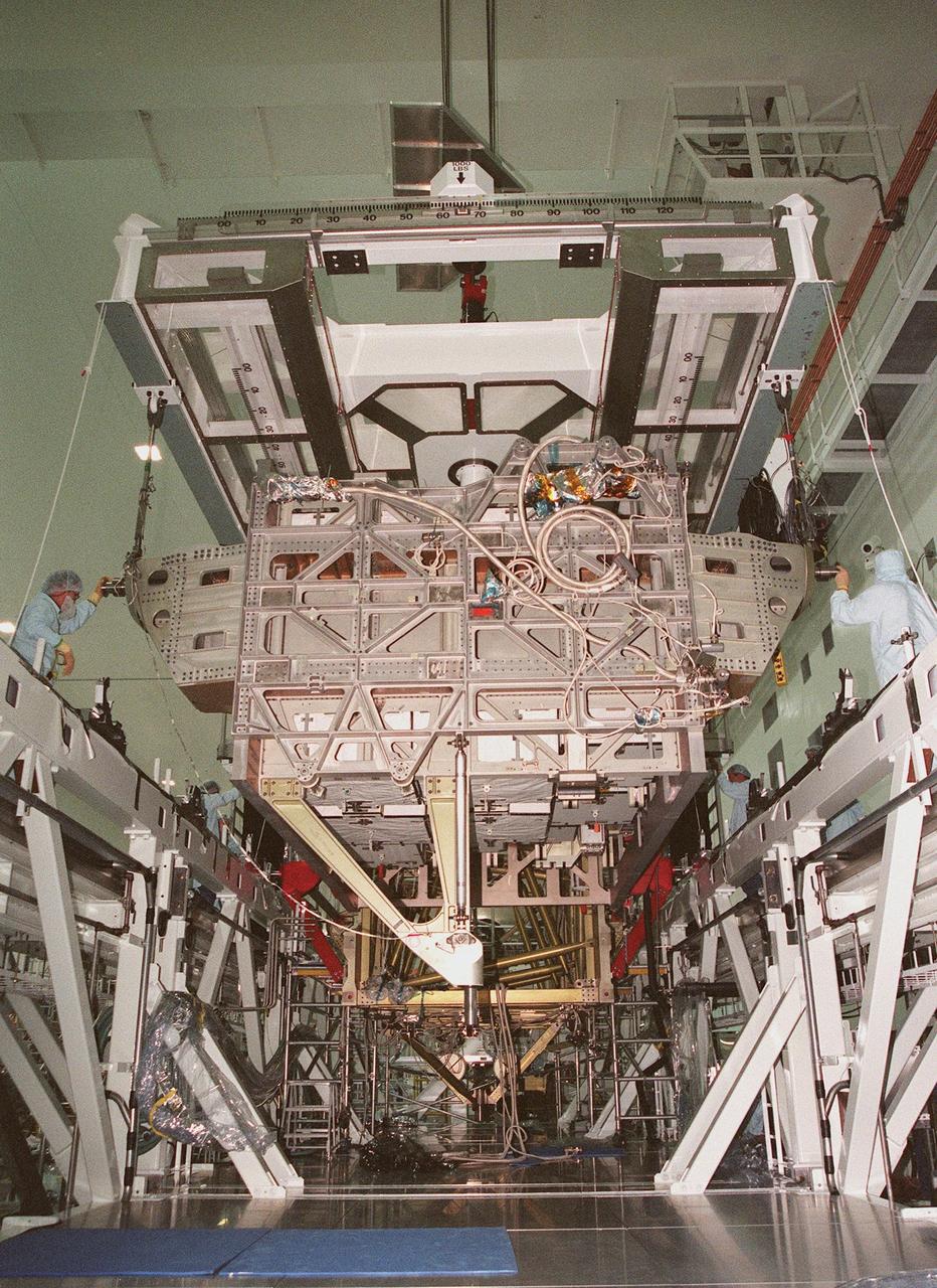
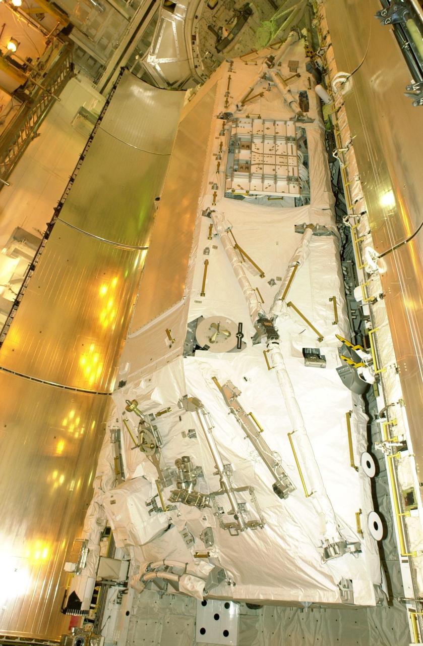
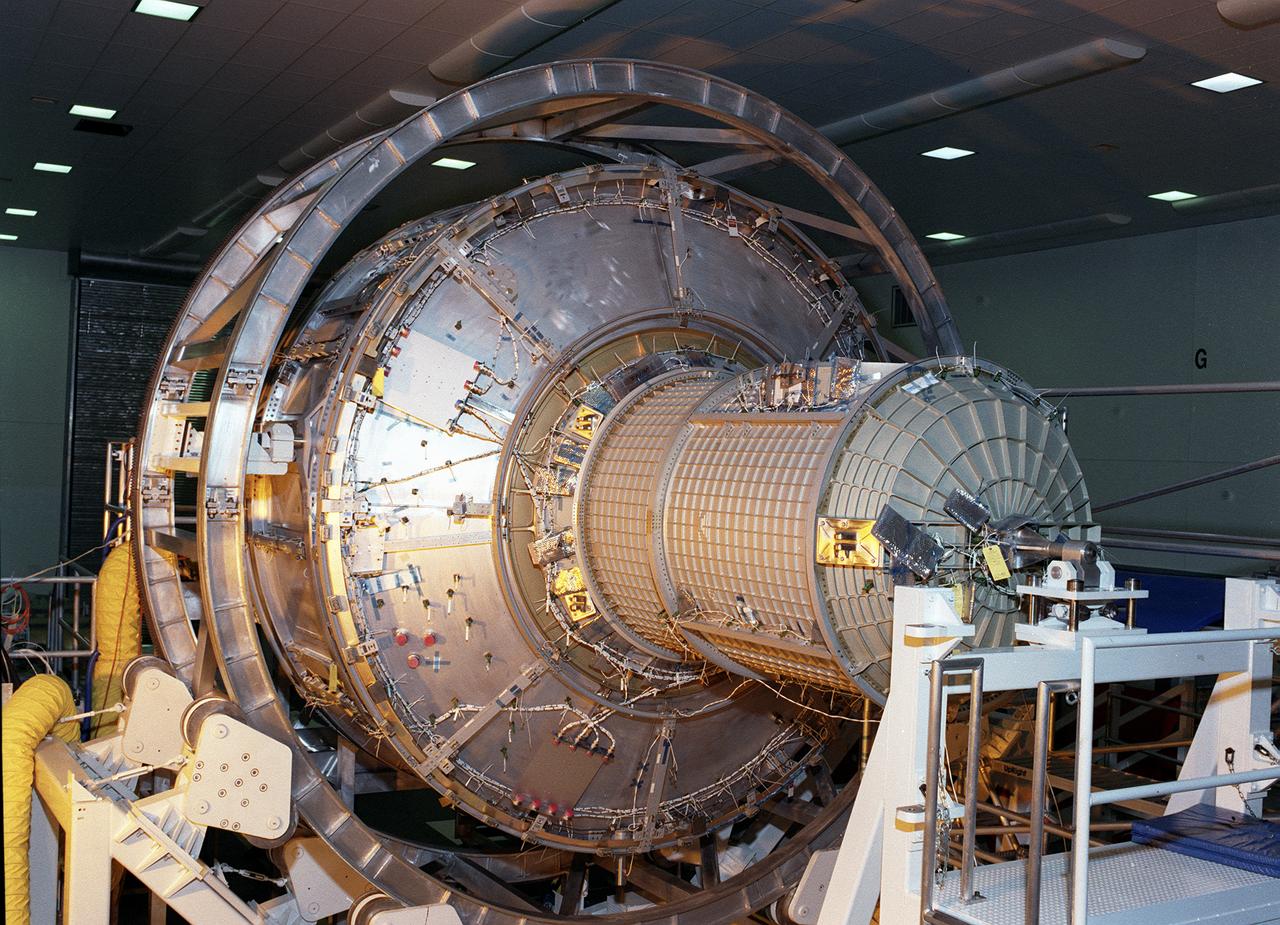
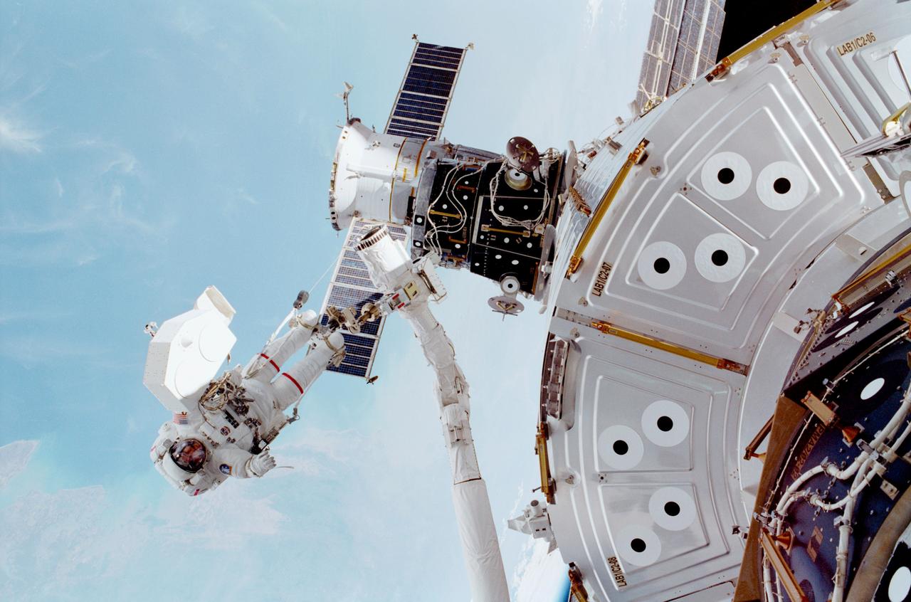
The Photovoltaic Module 1 Integrated Equipment Assembly (IEA) is moved past Node 1, seen at left, of the International Space Station (ISS) in Kennedy Space Center’s Space Station Processing Facility (SSPF). The IEA will be processed at the SSPF for flight on STS-97, scheduled for launch in April 1999. The IEA is one of four integral units designed to generate, distribute, and store power for the ISS. It will carry solar arrays, power storage batteries, power control units, and a thermal control system. The 16-foot-long, 16,850-pound unit is now undergoing preflight preparations in the SSPF
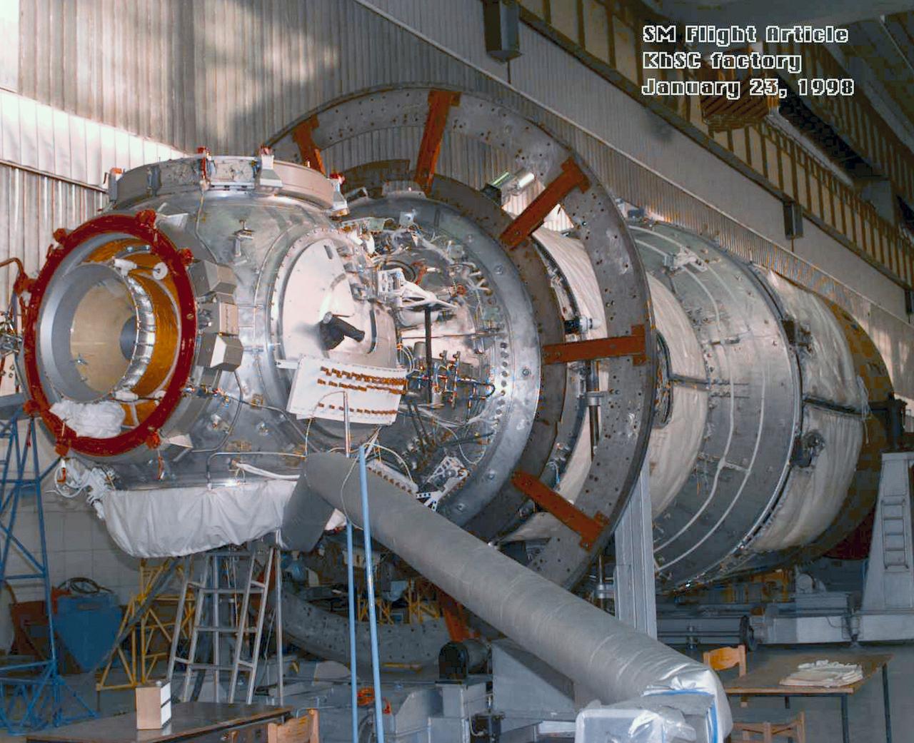
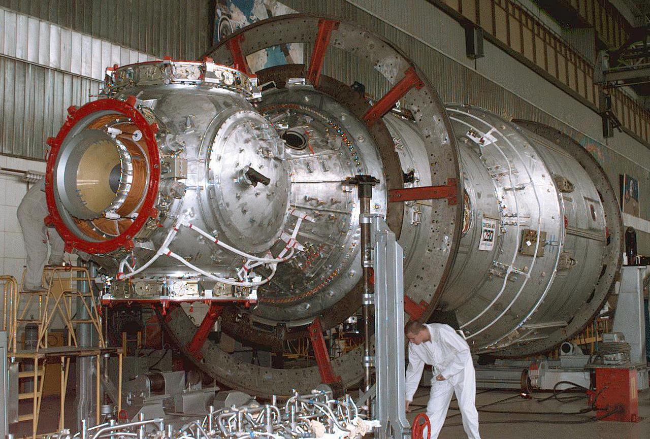
S98-04906 (23 Jan. 1998) --- A three-quarter frontal view of the flight article of the Service Module (SM) for the International Space Station (ISS). The first fully Russian contribution to ISS, the SM will provide early power, propulsion, life support, communications and living quarters for the station. It will be the third station element to be launched and join the United States-funded, Russian-built Functional Cargo Block (FGB) and the United States connecting module Node 1 in orbit.

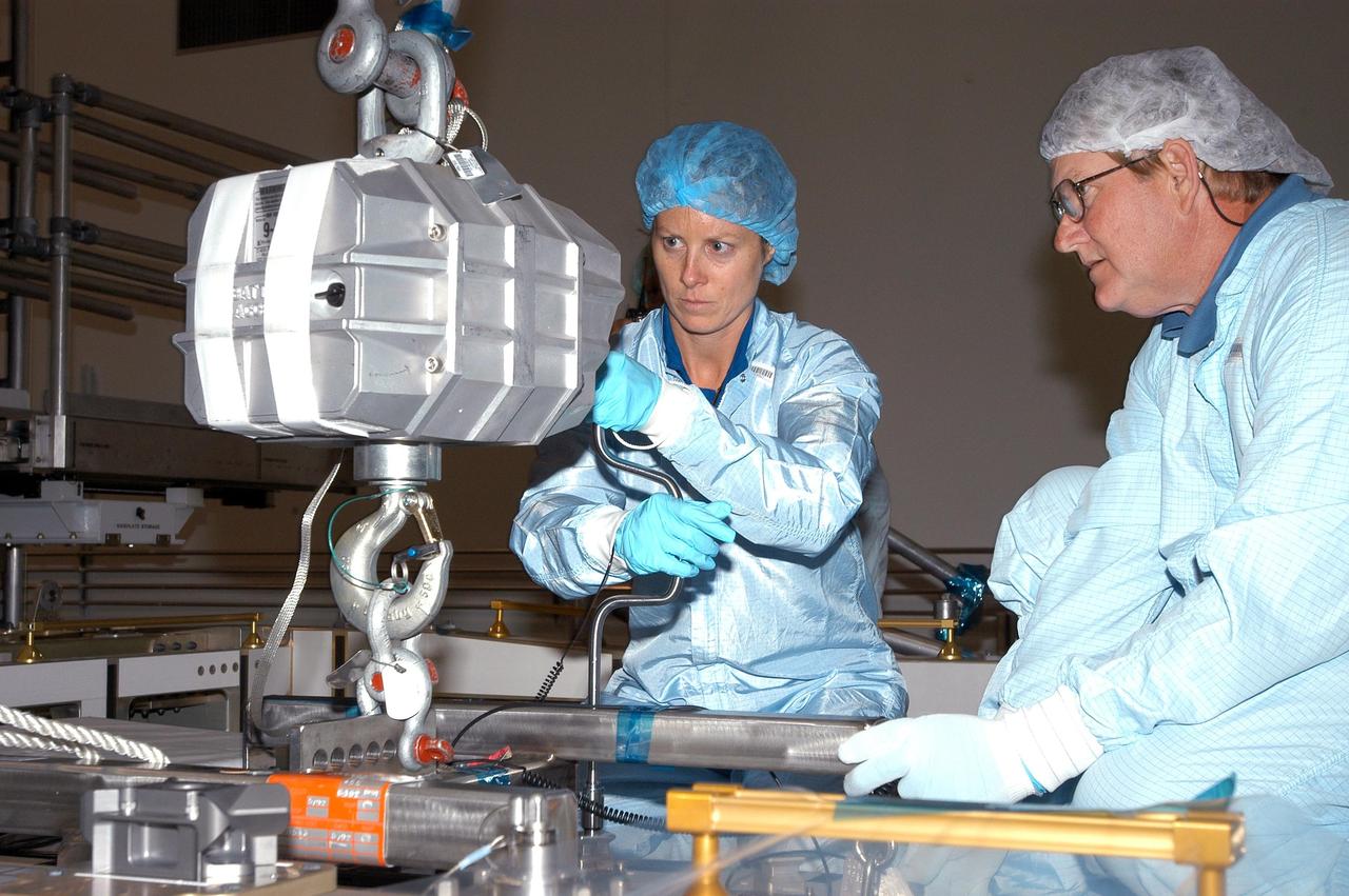
KENNEDY SPACE CENTER, FLA. - In the Space Station Processing Facility, astronaut Tracy Caldwell (left) assists a technician check out the Pump Flow Control Subsystem (PFCS) before it is installed on the upper deck of the S6 Truss. The PFCS pumps and controls the liquid ammonia used to cool the various Orbital Replacement Units on the Integrated Equipment Assembly that make up the S6 Photo-Voltaic Power Module on the International Space Station (ISS). The fourth starboard truss segment, the S6 Truss measures 112 feet long by 39 feet wide. The solar arrays are mounted on a “blanket” that can be folded like an accordion for delivery to the ISS. Once in orbit, astronauts will deploy the blankets to their full size. When completed, the Station's electrical power system (EPS) will use eight photovoltaic solar arrays to convert sunlight to electricity. Delivery of the S6 Truss, the last power module truss segment, is targeted for mission STS-119.

KENNEDY SPACE CENTER, FLA. - In the Space Station Processing Facility, astronaut Tracy Caldwell (second from left) assists technicians lower the Pump Flow Control Subsystem (PFCS) into position onto the upper deck of the S6 Truss. The PFCS pumps and controls the liquid ammonia used to cool the various Orbital Replacement Units on the Integrated Equipment Assembly that make up the S6 Photo-Voltaic Power Module on the International Space Station (ISS). The fourth starboard truss segment, the S6 Truss measures 112 feet long by 39 feet wide. Its solar arrays are mounted on a “blanket” that can be folded like an accordion for delivery to the ISS. Once in orbit, astronauts will deploy the blankets to their full size. When completed, the Station's electrical power system (EPS) will use eight photovoltaic solar arrays to convert sunlight to electricity. Delivery of the S6 Truss, the last power module truss segment, is targeted for mission STS-119.
KENNEDY SPACE CENTER, FLA. - Technicians attach a crane to the Pump Flow Control Subsystem (PFCS) in the Space Station Processing Facility. The PFCS pumps and controls the liquid ammonia used to cool the various Orbital Replacement Units on the Integrated Equipment Assembly that make up the S6 Photo-Voltaic Power Module on the International Space Station (ISS). The fourth starboard truss segment, the S6 Truss measures 112 feet long by 39 feet wide. Its solar arrays are mounted on a “blanket” that can be folded like an accordion for delivery to the ISS. Once in orbit, astronauts will deploy the blankets to their full size. When completed, the Station's electrical power system (EPS) will use eight photovoltaic solar arrays to convert sunlight to electricity. Delivery of the S6 Truss, the last power module truss segment, is targeted for mission STS-119.
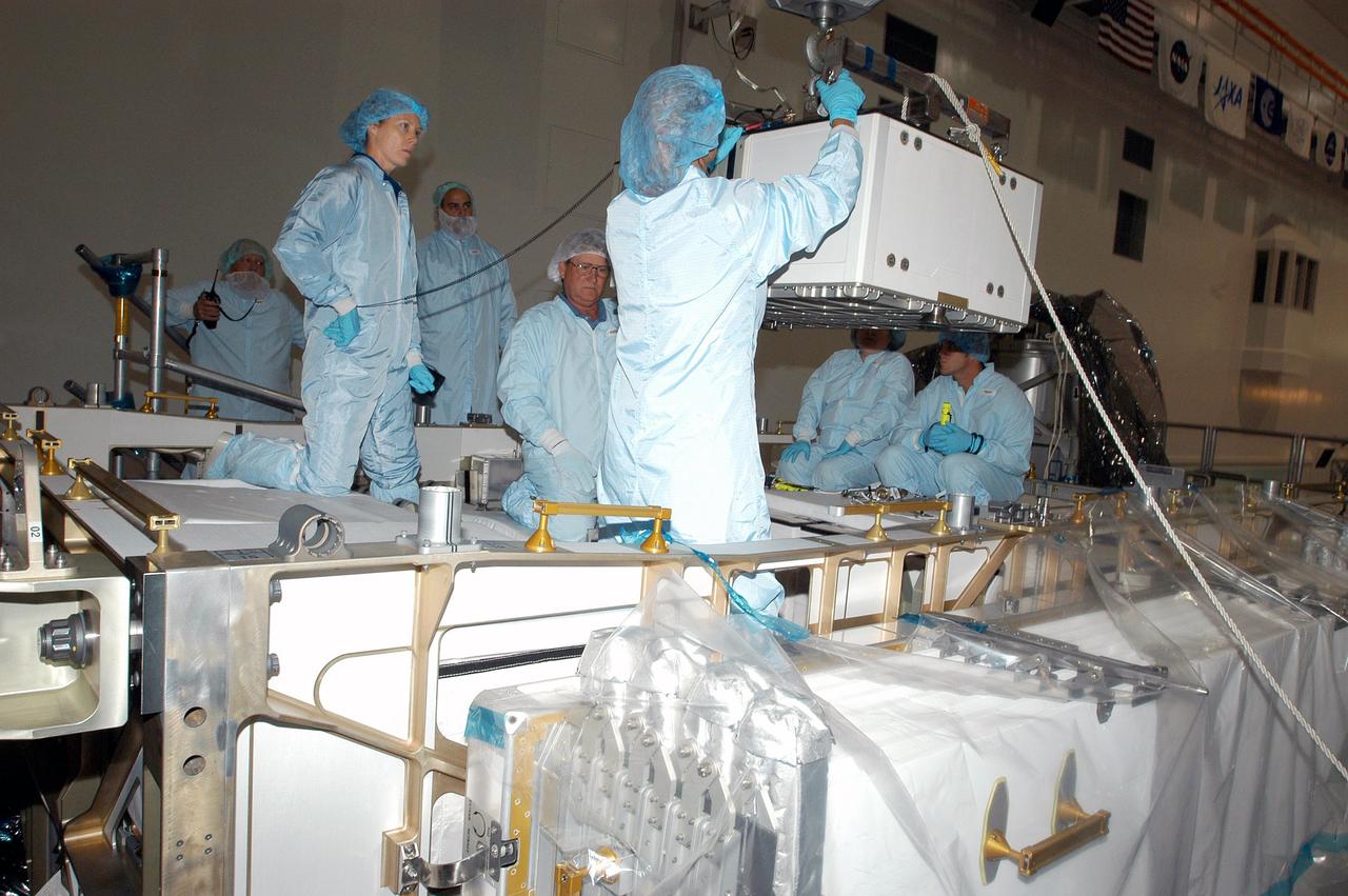
KENNEDY SPACE CENTER, FLA. - In the Space Station Processing Facility, astronaut Tracy Caldwell (second from left) assists technicians position the Pump Flow Control Subsystem (PFCS) over the upper deck of the S6 Truss. The PFCS pumps and controls the liquid ammonia used to cool the various Orbital Replacement Units on the Integrated Equipment Assembly that make up the S6 Photo-Voltaic Power Module on the International Space Station (ISS). The fourth starboard truss segment, the S6 Truss measures 112 feet long by 39 feet wide. Its solar arrays are mounted on a “blanket” that can be folded like an accordion for delivery to the ISS. Once in orbit, astronauts will deploy the blankets to their full size. When completed, the Station's electrical power system (EPS) will use eight photovoltaic solar arrays to convert sunlight to electricity. Delivery of the S6 Truss, the last power module truss segment, is targeted for mission STS-119.
KENNEDY SPACE CENTER, FLA. - In the Space Station Processing Facility, astronaut Tracy Caldwell (left) assists technicians install the Pump Flow Control Subsystem (PFCS) onto the upper deck of the S6 Truss. The PFCS pumps and controls the liquid ammonia used to cool the various Orbital Replacement Units on the Integrated Equipment Assembly that make up the S6 Photo-Voltaic Power Module on the International Space Station (ISS). The fourth starboard truss segment, the S6 Truss measures 112 feet long by 39 feet wide. Its solar arrays are mounted on a “blanket” that can be folded like an accordion for delivery to the ISS. Once in orbit, astronauts will deploy the blankets to their full size. When completed, the Station's electrical power system (EPS) will use eight photovoltaic solar arrays to convert sunlight to electricity. Delivery of the S6 Truss, the last power module truss segment, is targeted for mission STS-119.
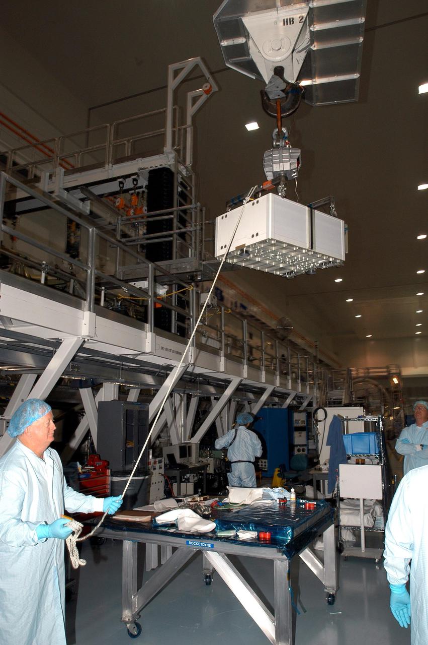
KENNEDY SPACE CENTER, FLA. - In the Space Station Processing Facility, a technician steadies the Pump Flow Control Subsystem (PFCS) as it is lifted and moved toward the S6 Truss. The PFCS pumps and controls the liquid ammonia used to cool the various Orbital Replacement Units on the Integrated Equipment Assembly that make up the S6 Photo-Voltaic Power Module on the International Space Station (ISS). The fourth starboard truss segment, the S6 Truss measures 112 feet long by 39 feet wide. Its solar arrays are mounted on a “blanket” that can be folded like an accordion for delivery to the ISS. Once in orbit, astronauts will deploy the blankets to their full size. When completed, the Station's electrical power system (EPS) will use eight photovoltaic solar arrays to convert sunlight to electricity. Delivery of the S6 Truss, the last power module truss segment, is targeted for mission STS-119.
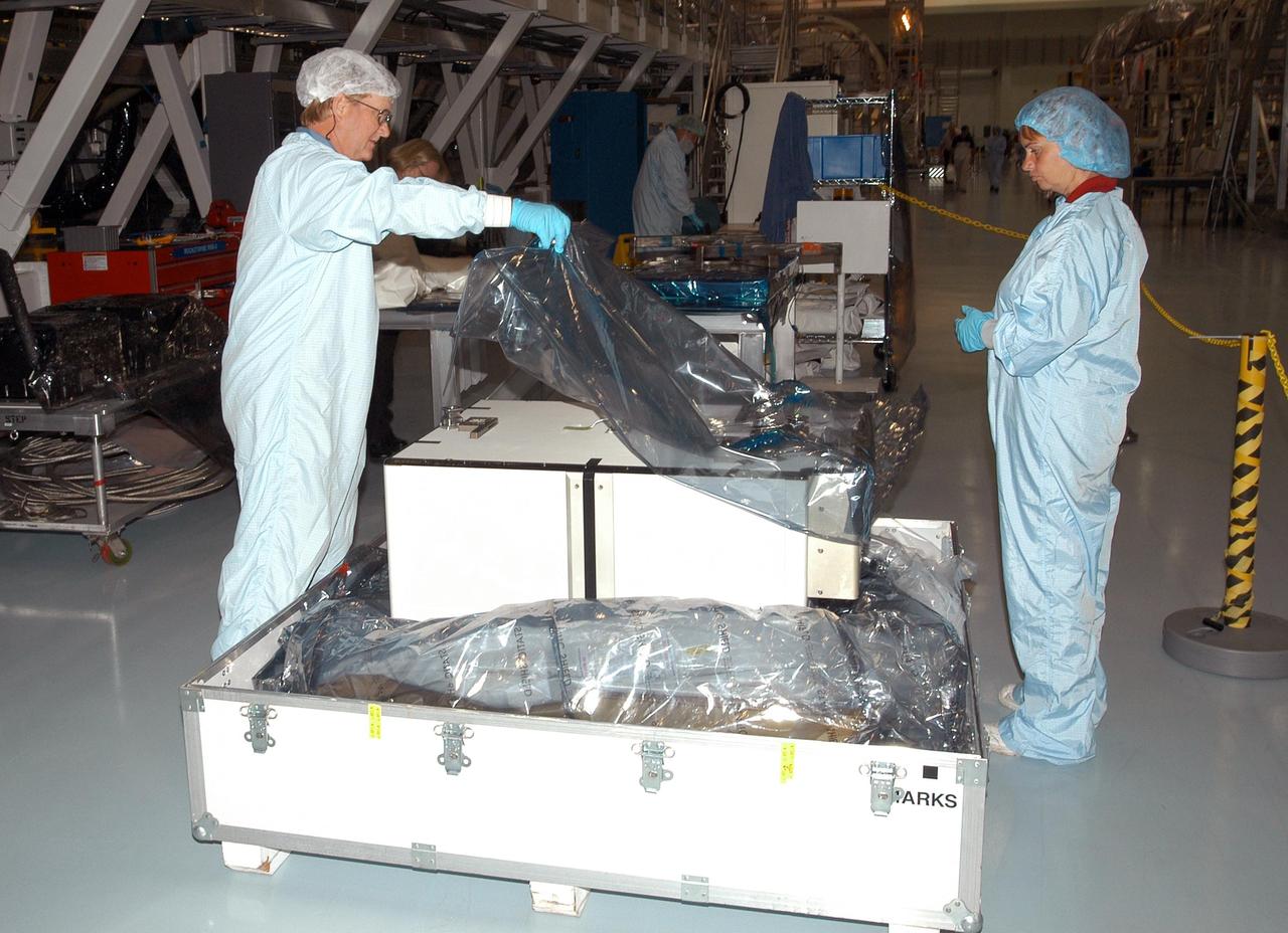
KENNEDY SPACE CENTER, FLA. - Unpacking of the Pump Flow Control Subsystem (PFCS) begins in the Space Station Processing Facility. The PFCS pumps and controls the liquid ammonia used to cool the various Orbital Replacement Units on the Integrated Equipment Assembly that make up the S6 Photo-Voltaic Power Module on the International Space Station (ISS). The fourth starboard truss segment, the S6 Truss measures 112 feet long by 39 feet wide. Its solar arrays are mounted on a “blanket” that can be folded like an accordion for delivery to the ISS. Once in orbit, astronauts will deploy the blankets to their full size. When completed, the Station's electrical power system will use eight photovoltaic solar arrays to convert sunlight to electricity. Delivery of the S6 Truss, the last power module truss segment, is targeted for mission STS-119.
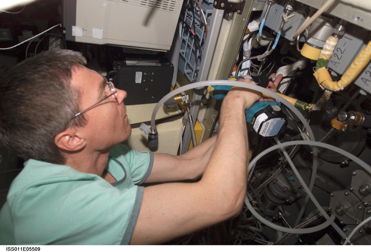
ISS011-E-05509 (5 May 2005) --- Cosmonaut Sergei K. Krikalev, Expedition 11 commander representing Russia's Federal Space Agency, uses a power tool as he makes repairs to the Elektron oxygen generator in the Zvezda Service Module of the International Space Station (ISS).
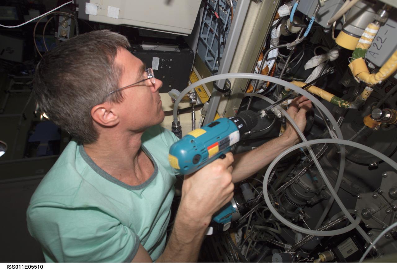
ISS011-E-05510 (5 May 2005) --- Cosmonaut Sergei K. Krikalev, Expedition 11 commander representing Russia's Federal Space Agency, uses a power tool as he makes repairs to the Elektron oxygen generator in the Zvezda Service Module of the International Space Station (ISS).
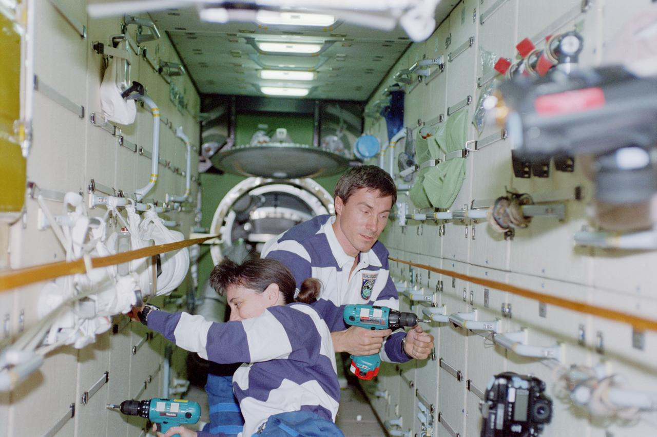
STS088-357-011 (4-15 Dec. 1998) --- Astronaut Nancy J. Currie, mission specialist, and cosmonaut Sergei K. Krikalev, mission specialist representing the Russian Space Agency (RSA), work in the FGB or Zarya Module of the International Space Station (ISS). The two are using battery powered tools to extract bolts.
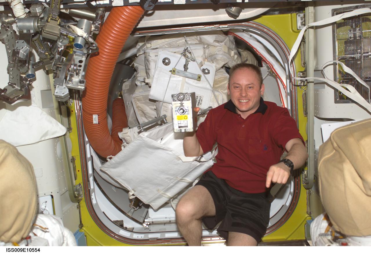
ISS009-E-10554 (4 June 2004) --- Astronaut Edward M. (Mike) Fincke, Expedition 9 NASA ISS science officer and flight engineer, holds the spare Remote Power Controller Module (RPCM) in the Quest airlock of the International Space Station (ISS). The spare is scheduled to replace the failed RPCM on the S0 (S-Zero) Truss.
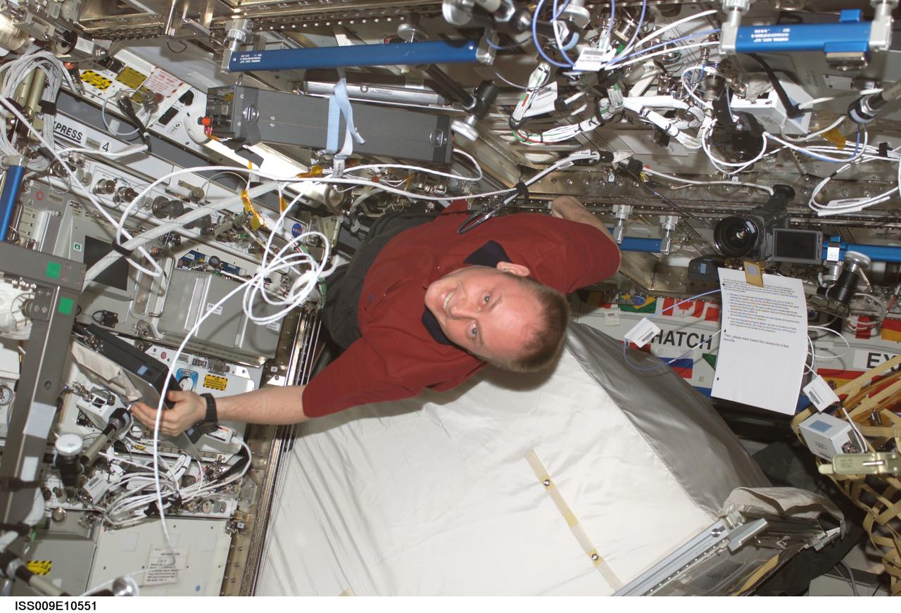
ISS009-E-10551 (4 June 2004) --- Astronaut Edward M. (Mike) Fincke, Expedition 9 NASA ISS science officer and flight engineer, moves the Zero-G Storage Rack (ZSR) in the Destiny laboratory of the International Space Station (ISS) in order to retrieve the spare Remote Power Controller Module (RPCM), scheduled to replace the failed RPCM on the S0 (S-Zero) Truss. Fincke is positioned above the ZSR, which has been pulled from the Express Rack.
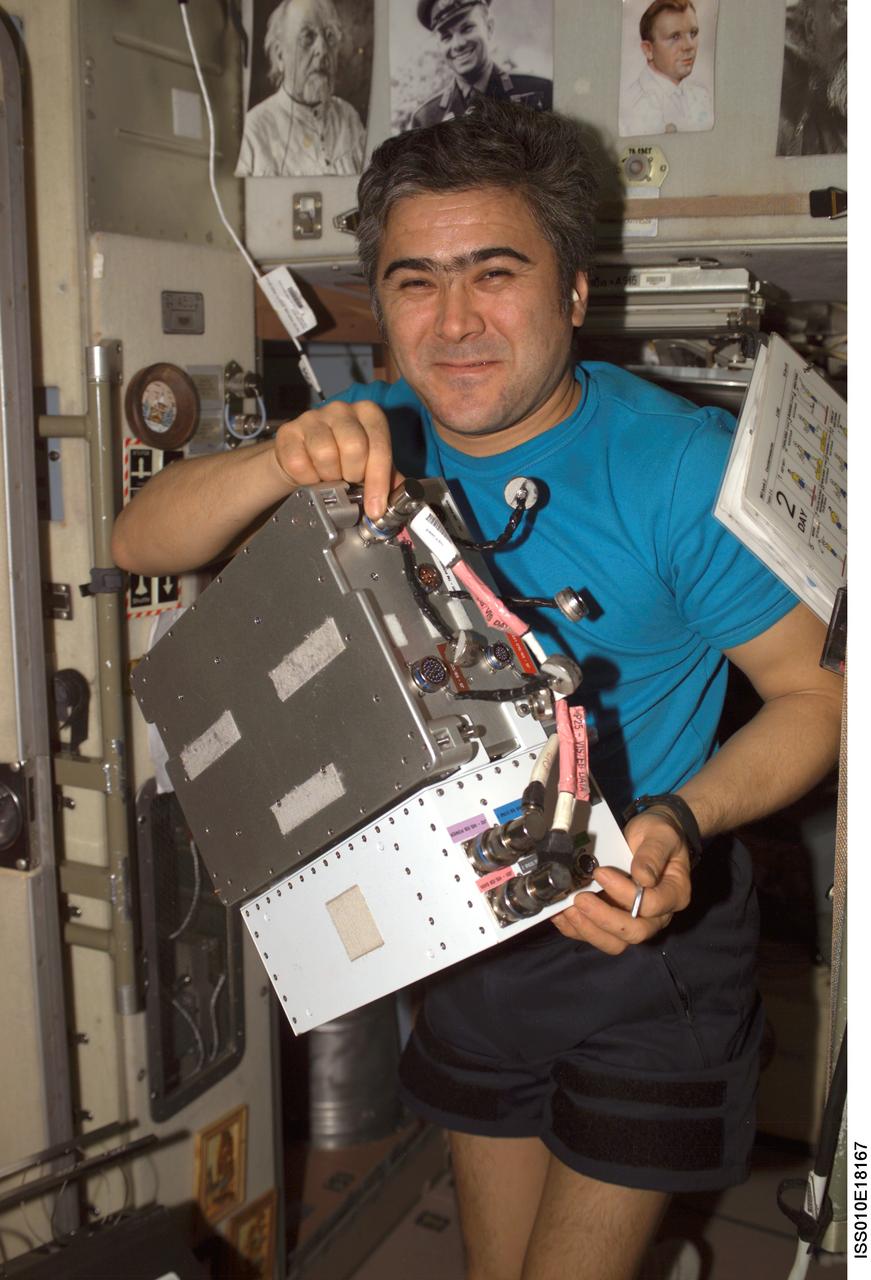
ISS010-E-18167 (17 February 2005) --- Cosmonaut Salizhan S. Sharipov, Expedition 10 flight engineer representing Russia's Federal Space Agency, holds an Electronic Box Assembly, and Violation Isolation and Stabilization (VIS) Controller Assembly, which is part of the Treadmill Vibration Isolation System (TVIS) in the Zvezda Service Module of the International Space Station (ISS). Also in view is a VIS/TM data cable and VIS/TM power cable. This box receives power and distributes it between the treadmill and the VIS subassemblies.
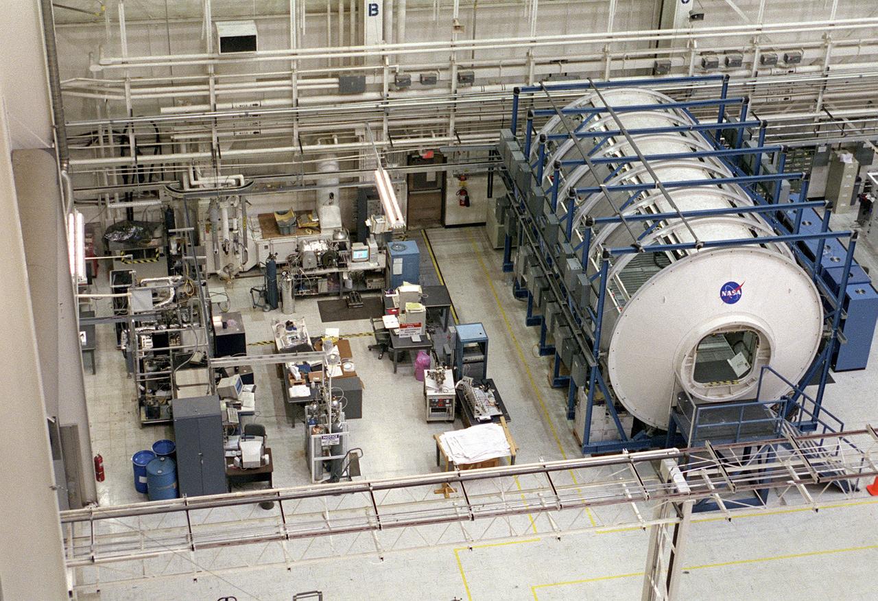
The Marshall Space Flight Center (MSFC) is responsible for designing and building the life support systems that will provide the crew of the International Space Station (ISS) a comfortable environment in which to live and work. Scientists and engineers at the MSFC are working together to provide the ISS with systems that are safe, efficient, and cost-effective. These compact and powerful systems are collectively called the Environmental Control and Life Support Systems, or simply, ECLSS. This is a view of the ECLSS and the Internal Thermal Control System (ITCS) Test Facility in building 4755, MSFC. In the foreground is the 3-module ECLSS simulator comprised of the U.S. Laboratory Module Simulator, Node 1 Simulator, and Node 3/Habitation Module Simulator. At center left is the ITCS Simulator. The main function of the ITCS is to control the temperature of equipment and hardware installed in a typical ISS Payload Rack.
The Marshall Space Flight Center (MSFC) is responsible for designing and building the life support systems that will provide the crew of the International Space Station (ISS) a comfortable environment in which to live and work. Scientists and engineers at the MSFC are working together to provide the ISS with systems that are safe, efficient, and cost-effective. These compact and powerful systems are collectively called the Environmental Control and Life Support Systems, or simply, ECLSS. This is a view of the ECLSS and the Internal Thermal Control System (ITCS) Test Facility in building 4755, MSFC. In the foreground is the 3-module ECLSS simulator comprised of the U.S. Laboratory Module Simulator, Node 1 Simulator, and Node 3/Habitation Module Simulator. On the left is the ITCS Simulator. The main function of the ITCS is to control the temperature of equipment and hardware installed in a typical ISS Payload Rack.
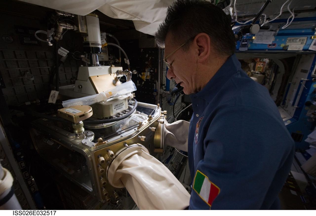
iss026e032517 (3/8/2011) --- European Space Agency (ESA) Paolo Nespoli works with the Light Microscopy Module (LMM) in the U.S. Laboratory. The Light Microscopy Module (LMM) is a modified commercial, highly flexible, state-of-the-art light imaging microscope facility that provides researchers with powerful diagnostic hardware and software onboard the International Space Station (ISS). The LMM enables novel research of microscopic phenomena in microgravity, with the capability of remotely acquiring and downloading digital images and videos across many levels of magnification.
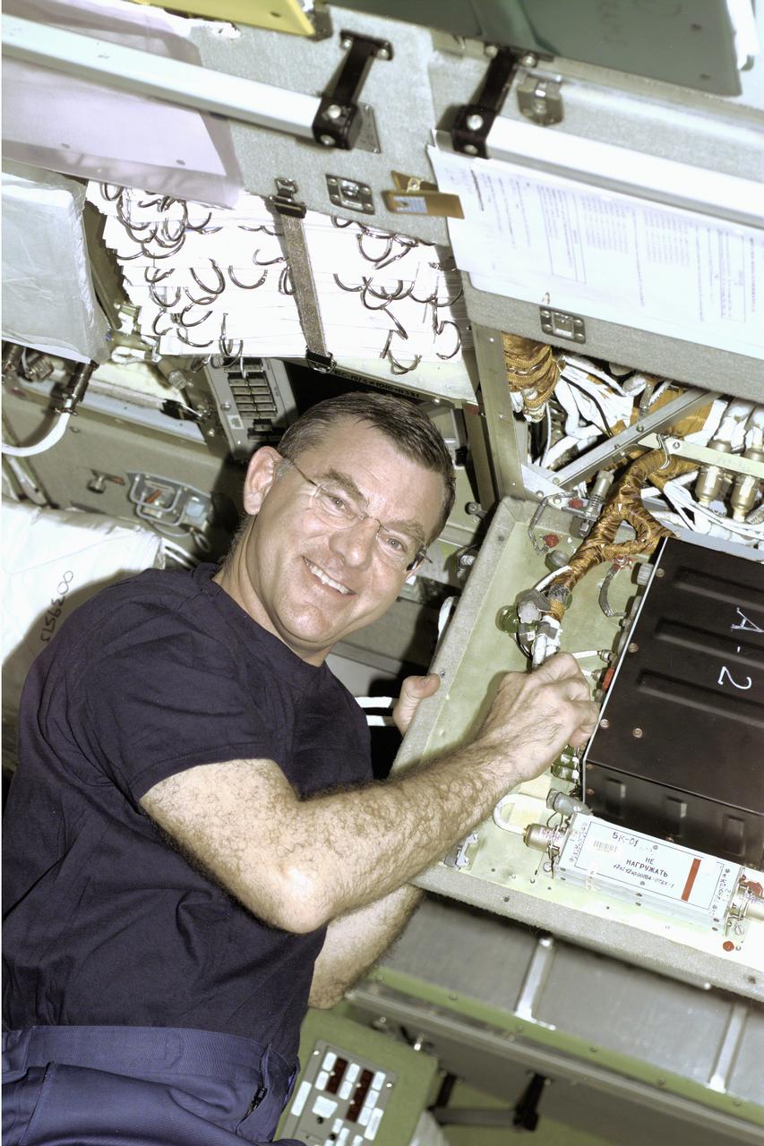
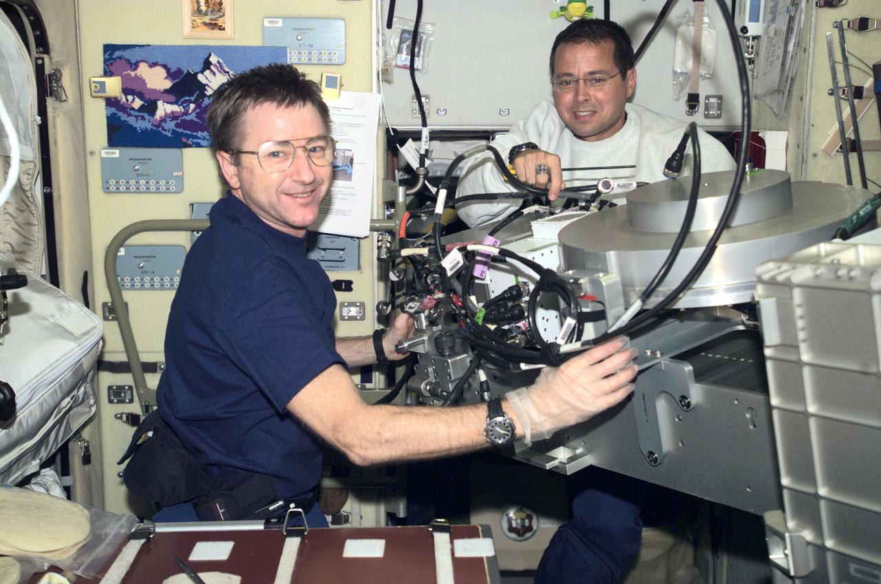
Astronaut James S. Voss, Expedition Two flight engineer, performs an electronics task in the Russian Zvezda Service Module on the International Space Station (ISS). Zvezda is linked to the Russian-built Functional Cargo Block (FGB), or Zarya, the first component of the ISS. Zarya was launched on a Russian Proton rocket prior to the launch of Unity, the first U.S.-built component to the ISS. Zvezda (Russian word for star), the third component of the ISS and the primary Russian contribution to the ISS, was launched by a three-stage Proton rocket on July 12, 2000. Zvezda serves as the cornerstone for early human habitation of the station, providing living quarters, a life support system, electrical power distribution, a data processing system, a flight control system, and a propulsion system. It also provides a communications system that includes remote command capabilities from ground flight controllers. The 42,000-pound module measures 43 feet in length and has a wing span of 98 feet. Similar in layout to the core module of Russia's Mir space station, it contains 3 pressurized compartments and 13 windows that allow ultimate viewing of Earth and space.
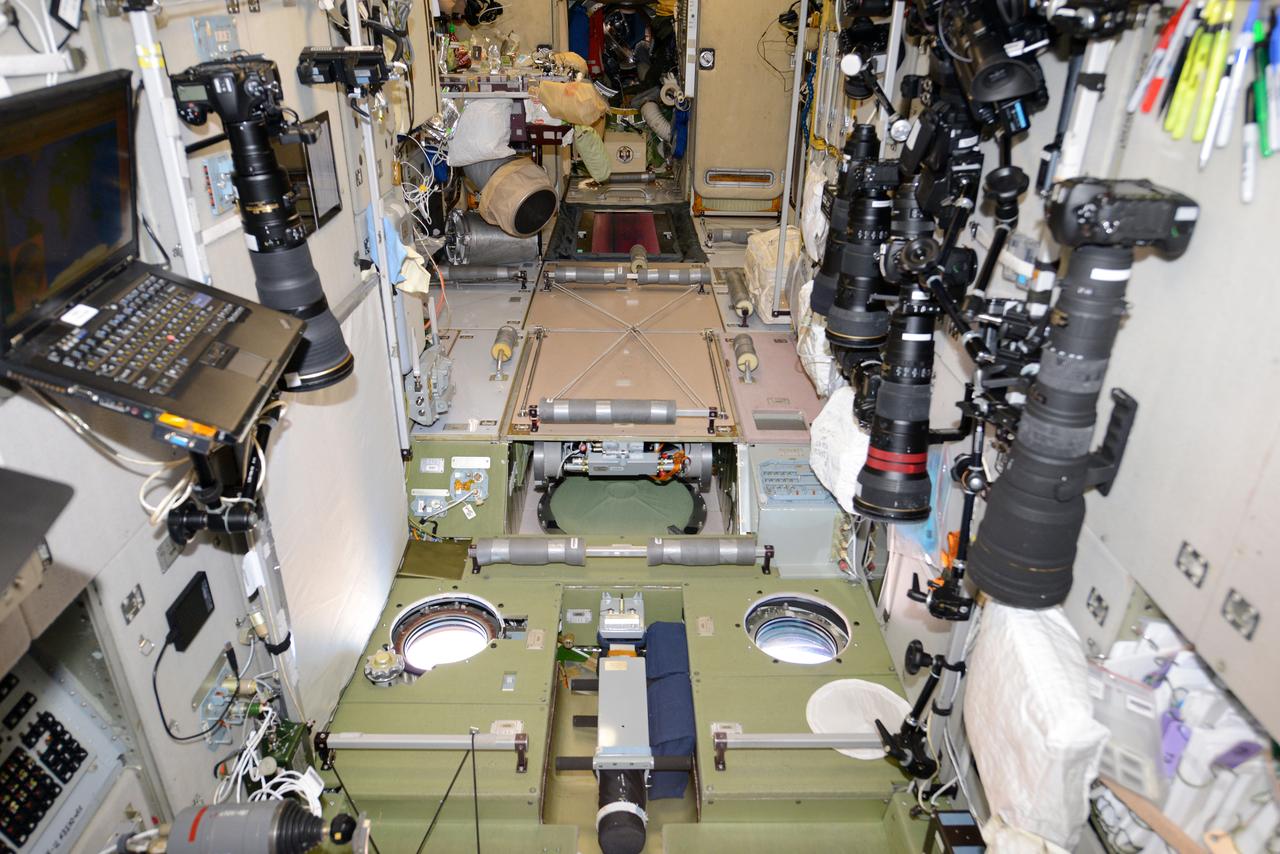
iss061e013837 (10/28/2019) --- A view of the Zvezda Service Module (SM) aboard the International Space Station (ISS). The Zvezda Service Module was the first fully Russian contribution to the International Space Station and served as the early cornerstone for the first human habitation of the station. The module provides station living quarters, life support systems, electrical power distribution, data processing systems, flight control systems and propulsion systems. It provides a communications system that includes remote command capabilities from ground flight controllers, and a docking port for Russian Soyuz and Progress spacecraft.
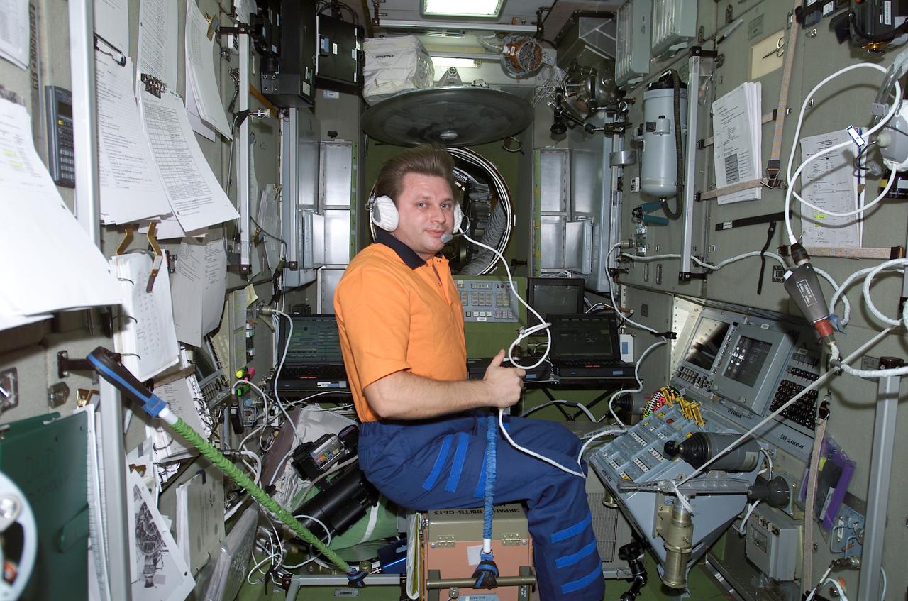
Cosmonaut Yury I. Onufrienko, Expedition Four mission commander, uses a communication system in the Russian Zvezda Service Module on the International Space Station (ISS). The Zvezda is linked to the Russian-built Functional Cargo Block (FGB) or Zarya, the first component of the ISS. Zarya was launched on a Russian Proton rocket prior to the launch of Unity. The third component of the ISS, Zvezda (Russian word for star), the primary Russian contribution to the ISS, was launched by a three-stage Proton rocket on July 12, 2000. Zvezda serves as the cornerstone for early human habitation of the station, providing living quarters, a life support system, electrical power distribution, a data processing system, flight control system, and propulsion system. It also provides a communications system that includes remote command capabilities from ground flight controllers. The 42,000-pound module measures 43 feet in length and has a wing span of 98 feet. Similar in layout to the core module of Russia's Mir space station, it contains 3 pressurized compartments and 13 windows that allow ultimate viewing of Earth and space.

Aboard the International Space Station (ISS), Cosmonaut and Expedition Three flight engineer Vladimir N. Dezhurov, representing Rosaviakosmos, talks with flight controllers from the Zvezda Service Module. Russian-built Zvezda is linked to the Functional Cargo Block (FGB), or Zarya, the first component of the ISS. Zarya was launched on a Russian Proton rocket prior to the launch of Unity. The third component of the ISS, Zvezda (Russian word for star), the primary Russian contribution to the ISS, was launched by a three-stage Proton rocket on July 12, 2000. Zvezda serves as the cornerstone for early human habitation of the Station, providing living quarters, a life support system, electrical power distribution, a data processing system, flight control system, and propulsion system. It also provides a communications system that includes remote command capabilities from ground flight controllers. The 42,000-pound module measures 43 feet in length and has a wing span of 98 feet. Similar in layout to the core module of Russia's Mir space station, it contains 3 pressurized compartments and 13 windows that allow ultimate viewing of Earth and space.
Astronauts Frank L. Culbertson, Jr. (left), Expedition Three mission commander, and Daniel W. Bursch, Expedition Four flight engineer, work in the Russian Zvezda Service Module on the International Space Station (ISS). Zvezda is linked to the Russian built Functional Cargo Block (FGB), or Zarya, the first component of the ISS. Zarya was launched on a Russian Proton rocket prior to the launch of Unity. The third component of the ISS, Zvezda (Russian word for star), the primary Russian contribution to the ISS, was launched by a three-stage Proton rocket on July 12, 2000. Zvezda serves as the cornerstone for early human habitation of the Station, providing living quarters, a life support system, electrical power distribution, a data processing system, a flight control system, and a propulsion system. It also provides a communications system that includes remote command capabilities from ground flight controllers. The 42,000 pound module measures 43 feet in length and has a wing span of 98 feet. Similar in layout to the core module of Russia's Mir space station, it contains 3 pressurized compartments and 13 windows that allow ultimate viewing of Earth and space.
Workers in the Space Station Processing Facility look at the Passive Common Berthing Mechanism (PCBM) that will be attached to the Z1 integrated truss structure, a component of the International Space Station (ISS). The truss will be used for the temporary installation of the P6 truss segment to the Unity connecting module. The P6 truss segment contains the solar arrays and batteries which will provide early station power. The truss is scheduled to be launched aboard STS-92 in late 1999
Workers in the Space Station Processing Facility watch as cables and a crane lift the Passive Common Berthing Mechanism (PCBM) before mating it to the Z1 integrated truss structure, a component of the International Space Station (ISS). The Z1 truss will be used for the temporary installation of the P6 truss segment to the Unity connecting module. The P6 truss segment contains the solar arrays and batteries which will provide early station power. The truss is scheduled to be launched aboard STS-92 in late 1999
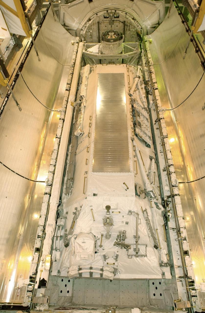
KENNEDY SPACE CENTER, FLA. -- At Launch Pad 39B, Space Shuttle Atlantis' payload bay doors are ready to be closed. The Shuttle payload includes the S0 Integrated Truss Structure (ITS), the Canadian Mobile Transporter, power distribution system modules, a heat pipe radiator for cooling, computers and a pair of rate gyroscopes. The mission is the 13th assembly flight to the ISS and includes four spacewalks to attach the S0 truss to the U.S. Lab Destiny. Launch is scheduled for April 4.
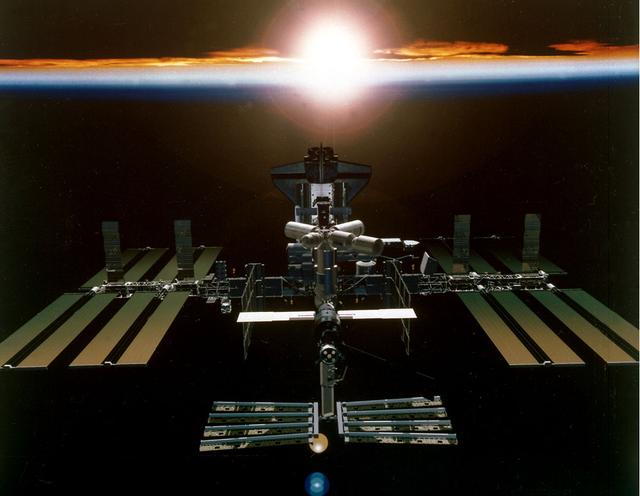
Artist's digital concept of the International Space Station (ISS), a gateway to permanent human presence in space, after all assembly is completed in Year 2003. The Station will be powered by almost an acre of solar panels and have a mass of almost one million pounds. Station modules are being provided by the United States, Russia, Japan, and Europe. Canada is providing a mechanical arm and Canada Hand. Sixteen countries are cooperating to provide a multidisciplinary laboratory, technology test bed, and observatory that will provide an unprecedented undertaking in scientific, technological, and international experimentation.
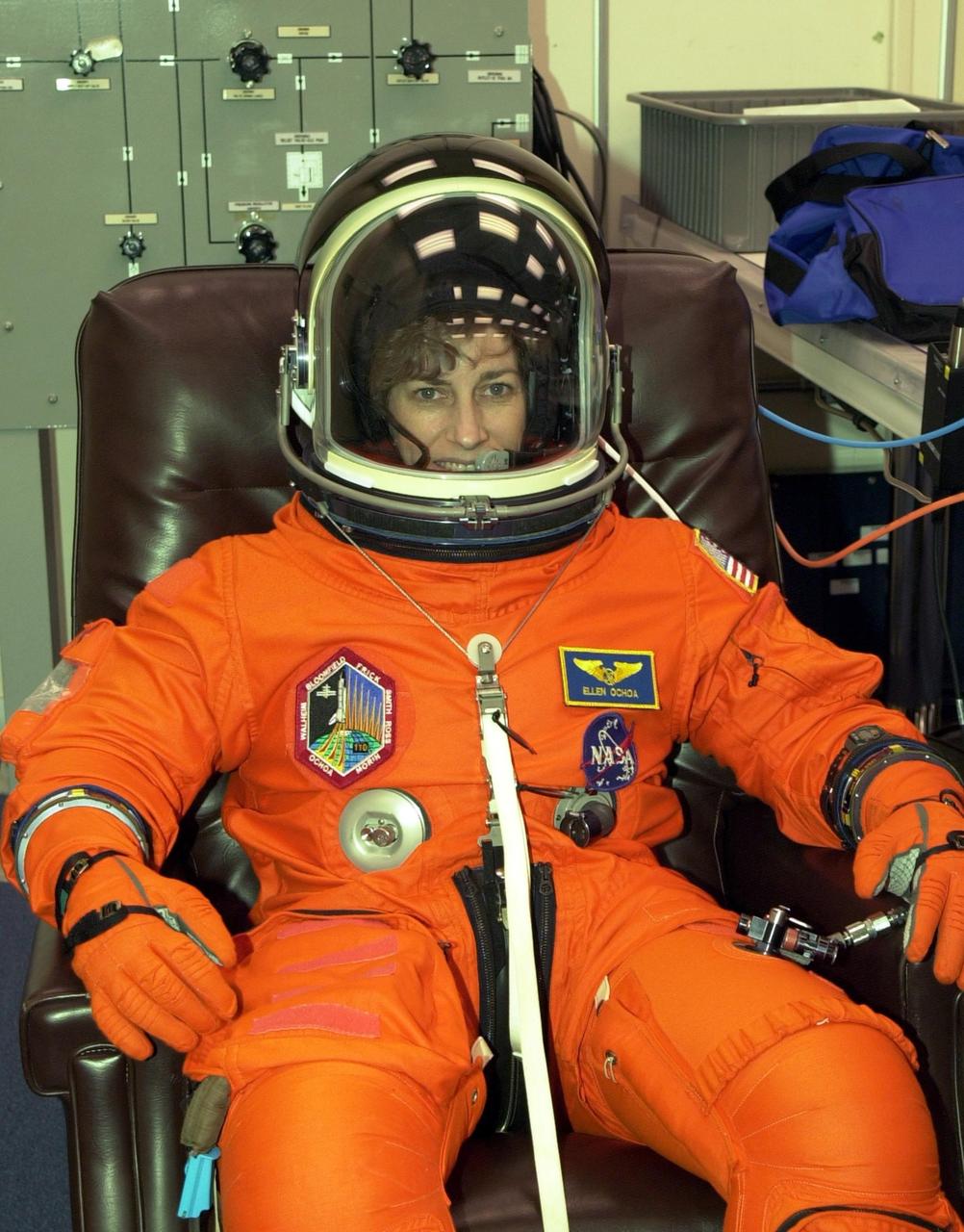
KENNEDY SPACE CENTER, FLA. -- STS-110 Mission Specialist Ellen Ochoa has a final check of her launch and entry suit in preparation for launch April 4. This flight will be her fourth. The STS-110 payload includes the S0 Integrated Truss Structure (ITS), the Canadian Mobile Transporter, power distribution system modules, a heat pipe radiator for cooling, computers and a pair of rate gyroscopes. The 11-day mission is the 13th assembly flight to the ISS and includes four spacewalks to attach the S0 truss to the U.S. Lab Destiny
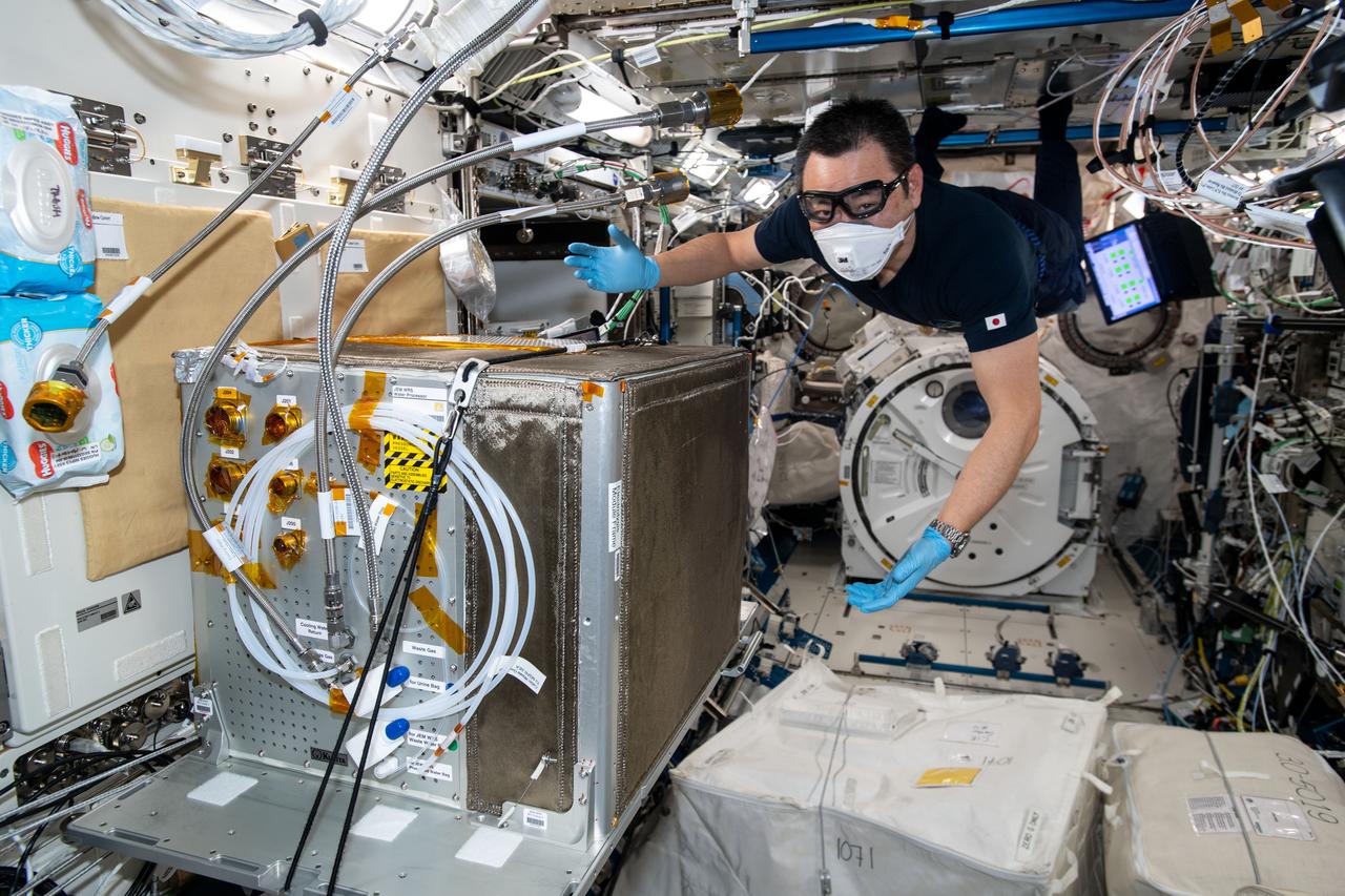
iss065e333421 (8/30/2021) --- Japan Aerospace Exploration Agency (JAXA) astronaut Akihiko Hoshide is photographed during the Japanese Experiment Module (JEM) Water Recovery System (JWRS) Gas Trap and Bypass Line Installation. Future water recovery systems will require high recovery rates, a more compact size, and less power consumption than conventional systems. The JWRS demonstrates new technologies on orbit, aboard the International Space Station (ISS), to meet these requirements.
Workers in the Space Station Processing Facility look at the Passive Common Berthing Mechanism (PCBM) that will be attached to the Z1 integrated truss structure, a component of the International Space Station (ISS). The Z1 truss will be used for the temporary installation of the P6 truss segment to the Unity connecting module. The P6 truss segment contains the solar arrays and batteries which will provide early station power. The truss is scheduled to be launched aboard STS-92 in late 1999
KENNEDY SPACE CENTER, FLA. -- At Launch Pad 39B, Space Shuttle Atlantis' payload bay doors are ready to be closed. The Shuttle payload includes the S0 Integrated Truss Structure (ITS), the Canadian Mobile Transporter, power distribution system modules, a heat pipe radiator for cooling, computers and a pair of rate gyroscopes. The mission is the 13th assembly flight to the ISS and includes four spacewalks to attach the S0 truss to the U.S. Lab Destiny. Launch is scheduled for April 4.
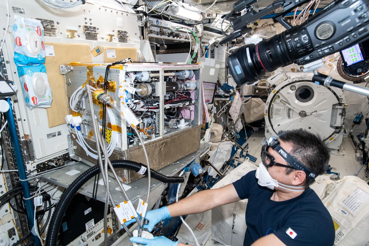
iss065e333427 (8/30/2021) --- Japan Aerospace Exploration Agency (JAXA) astronaut Akihiko Hoshide is photographed during the Japanese Experiment Module (JEM) Water Recovery System (JWRS) Gas Trap and Bypass Line Installation. Future water recovery systems will require high recovery rates, a more compact size, and less power consumption than conventional systems. The JWRS demonstrates new technologies on orbit, aboard the International Space Station (ISS), to meet these requirements.
KENNEDY SPACE CENTER, FLA. - A worker at Launch Pad 39B prepares for the closing of Space Shuttle Atlantis' payload bay doors. The Shuttle payload includes the S0 Integrated Truss Structure (ITS), the Canadian Mobile Transporter, power distribution system modules, a heat pipe radiator for cooling, computers and a pair of rate gyroscopes. The mission is the 13th assembly flight to the ISS and includes four spacewalks to attach the S0 truss to the U.S. Lab Destiny. Launch is scheduled for April 4.
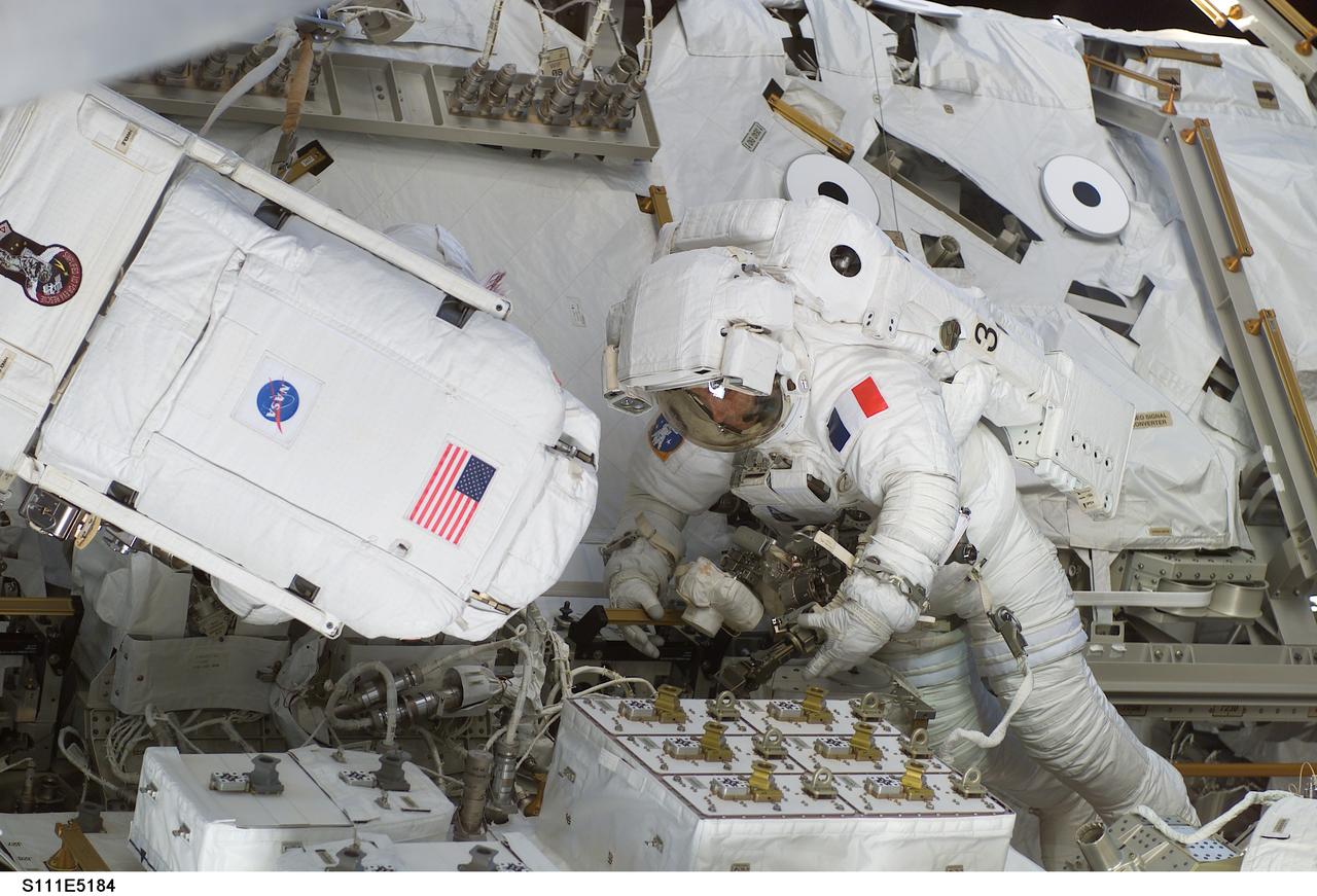
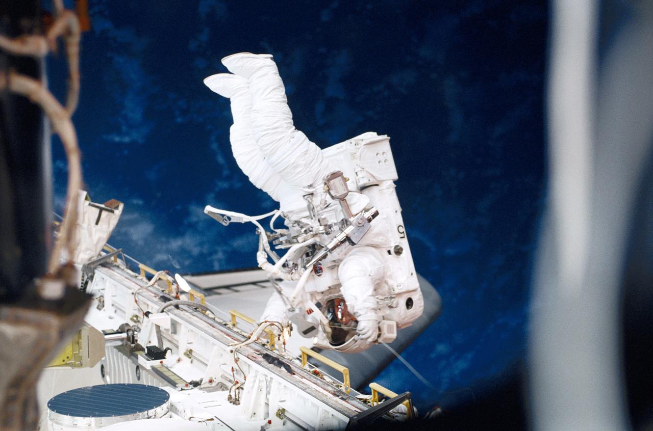
STS111-E-5184 (11 June 2002) --- Astronauts Franklin R. Chang-Diaz (left) and Philippe Perrin, both mission specialists, work on the Mobile Remote Servicer Base System (MBS) and the Mobile Transporter on the International Space Station (ISS) during the second scheduled session of extravehicular activity (EVA) for the STS-111 mission. The boxes in front of the spacewalkers are the Canadian Remote Power Control Modules (RPCM). The S0 (S-zero) Truss is partially visible in the background. Perrin represents CNES, the French Space Agency.

STS111-E-5183 (11 June 2002) --- Astronauts Franklin R. Chang-Diaz (left) and Philippe Perrin, both mission specialists, work on the Mobile Remote Servicer Base System (MBS) and the Mobile Transporter on the International Space Station (ISS) during the second scheduled session of extravehicular activity (EVA) for the STS-111 mission. The boxes in front of the spacewalkers are the Canadian Remote Power Control Modules (RPCM). The S0 (S-zero) Truss is partially visible in the background. Perrin represents CNES, the French Space Agency.
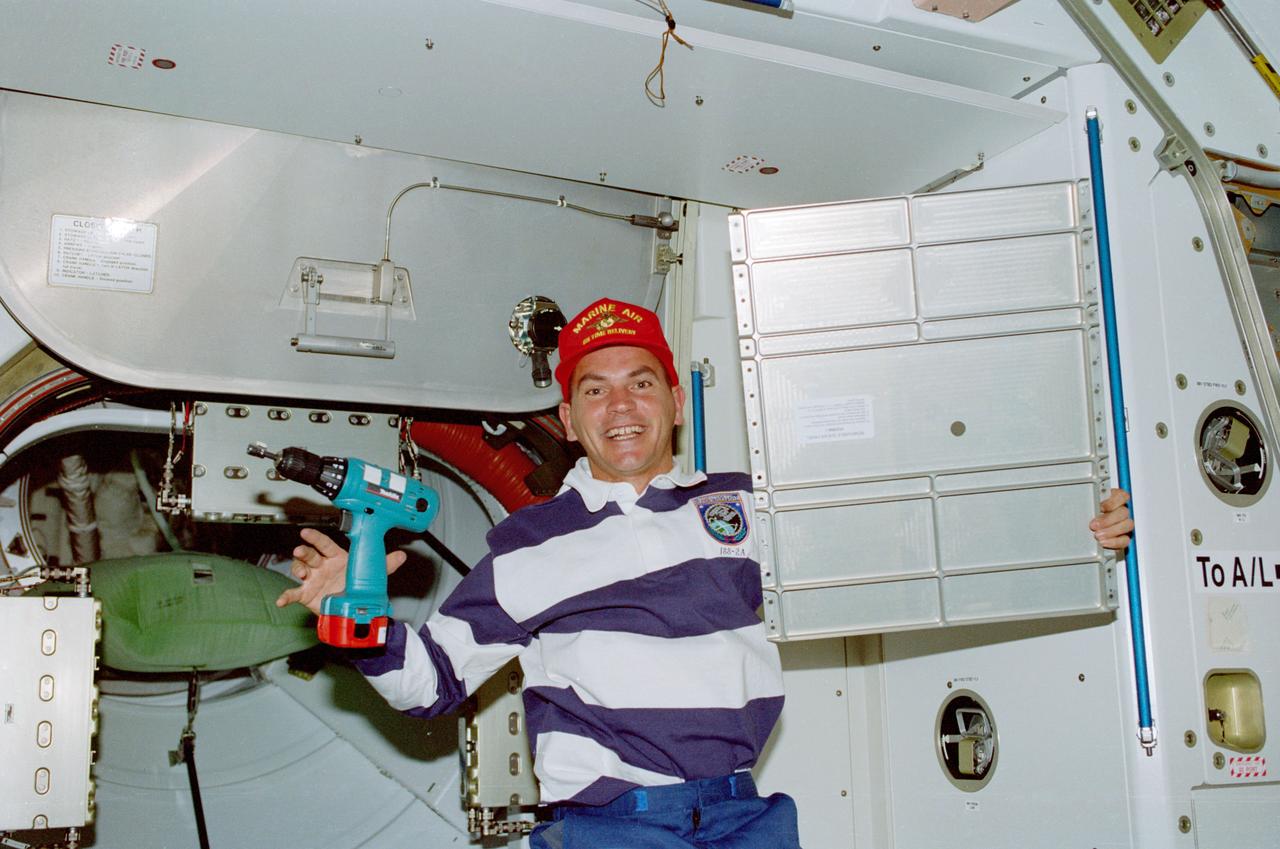
STS088-359-003 (4-15 Dec. 1998) --- Astronaut Frederick W. ?Rick? Sturckow, pilot, holds up a panel while putting final touches on the interior of Node 1 or Unity. Sturckow, who had been working with a battery-powered tool, was joined by other crew members in preparing the module for its International Space Station (ISS) duty.
Workers in the Space Station Processing Facility watch the Passive Common Berthing Mechanism (PCBM) lifted high to move it over to the Z1 integrated truss structure at right. It will be mated to the Z1 truss, a component of the International Space Station (ISS). The Z1 truss will be used for the temporary installation of the P6 truss segment to the Unity connecting module. The P6 truss segment contains the solar arrays and batteries which will provide early station power. The truss is scheduled to be launched aboard STS-92 in late 1999

iss062e103684 (3/21/2020) --- A view of the rack containing CBEF-L (Cell Biology Experiment Facility-L) IU1 and CBEF-L IU2 in the Japanese Experiment Module (JEM) Pressurized Module (JPM). aboard the International Space Station (ISS). Cell Biology Experiment Facility-L (CBEF-L) is a Japan Aerospace Exploration Agency (JAXA) new subrack facility, which is an upgraded facility of the original Cell Biology Experiment Facility (CBEF) currently aboard the International Space Station (ISS). CBEF-L provides new capabilities with additional new resources such as Full High Definition video interface, Ethernet, 24 VDC power supply, and a larger diameter centrifugal test environment. By using the original CBEF and CBEF-L as one facility for the same experiment, the payload user is provided with an upgraded experimental environment that can handle the processing of more experimental samples for a wider array of experiments.
The Marshall Space Flight Center (MSFC) is responsible for designing and building the life support systems that will provide the crew of the International Space Station (ISS) a comfortable environment in which to live and work. Scientists and engineers at the MSFC are working together to provide the ISS with systems that are safe, efficient and cost-effective. These compact and powerful systems are collectively called the Environmental Control and Life Support Systems, or simply, ECLSS. This is an exterior view of the U.S. Laboratory Module Simulator containing the ECLSS Internal Thermal Control System (ITCS) testing facility at MSFC. At the bottom right is the data acquisition and control computers (in the blue equipment racks) that monitor the testing in the facility. The ITCS simulator facility duplicates the function, operation, and troubleshooting problems of the ITCS. The main function of the ITCS is to control the temperature of equipment and hardware installed in a typical ISS Payload Rack.
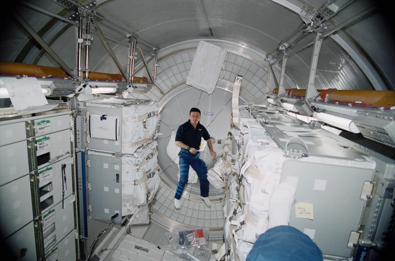
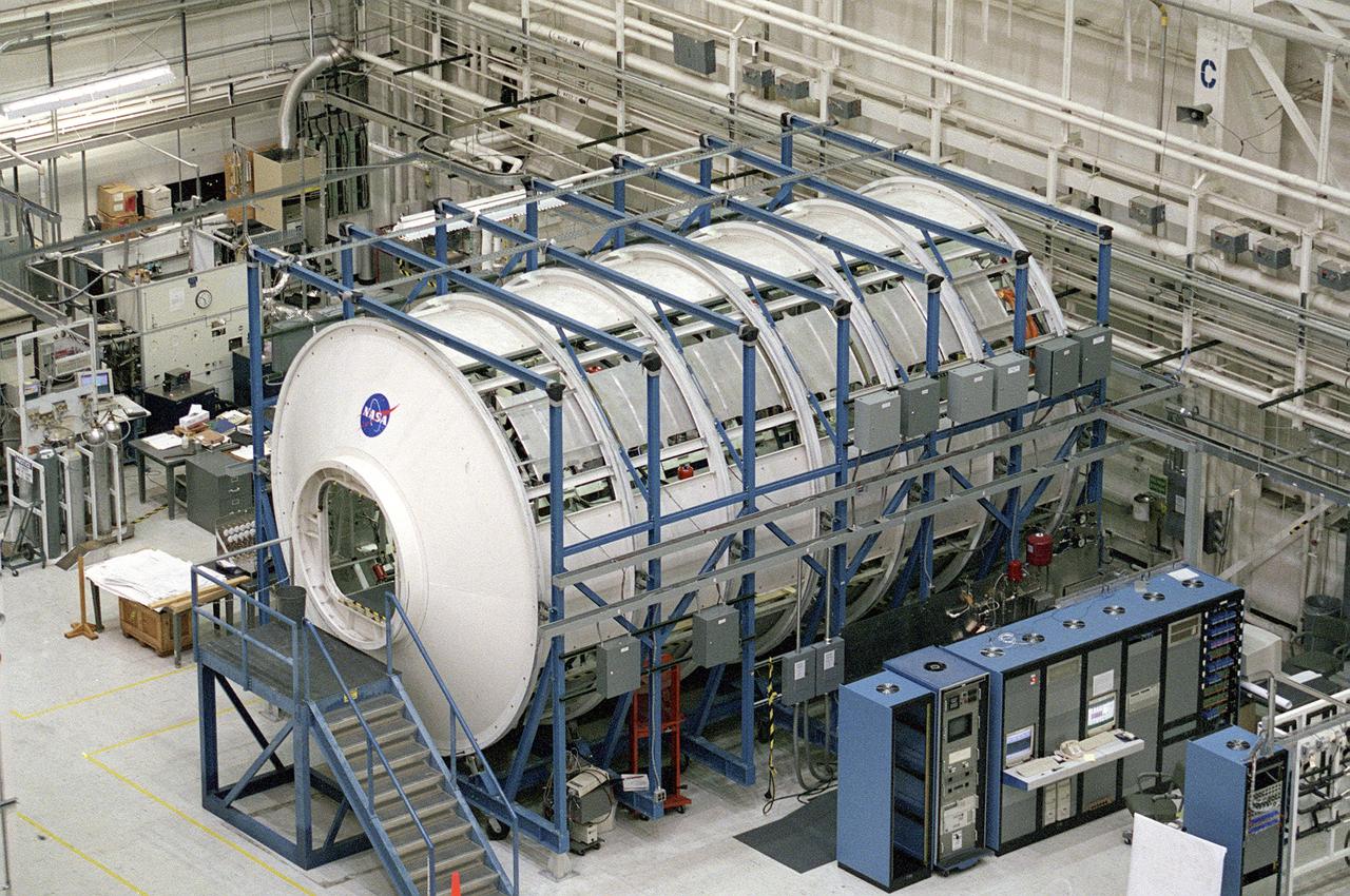
A crewmember of Expedition One, cosmonaut Yuri P. Gidzenko, is dwarfed by transient hardware aboard Leonardo, the Italian Space Agency-built Multi-Purpose Logistics Module (MPLM), a primary cargo of the STS-102 mission. The Leonardo MPLM is the first of three such pressurized modules that will serve as the International Space Station's (ISS's) moving vans, carrying laboratory racks filled with equipment, experiments and supplies to and from the Space Station aboard the Space Shuttle. The cylindrical module is approximately 21-feet long and 15- feet in diameter, weighing almost 4.5 tons. It can carry up to 10 tons of cargo into 16 standard Space Station equipment racks. Of the 16 racks the module can carry, 5 can be furnished with power, data, and fluid to support refrigerators or freezers. In order to function as an attached station module as well as a cargo transport, the logistics module also includes components that provide life support, fire detection and suppression, electrical distribution, and computer functions. The eighth Shuttle mission to visit the ISS, the STS-102 mission served as a crew rotation flight. It delivered the Expedition Two crew to the Station and returned the Expedition One crew back to Earth.
STS-102 astronaut and mission specialist, Andrew S.W. Thomas, gazes through an aft window of the Space Shuttle Orbiter Discovery as it approaches the docking bay of the International Space Station (ISS). Launched March 8, 2001, STS-102's primary cargo was the Leonardo, the Italian Space Agency-built Multipurpose Logistics Module (MPLM). The Leonardo MPLM is the first of three such pressurized modules that will serve as the ISS's moving vans, carrying laboratory racks filled with equipment, experiments, and supplies to and from the Station aboard the Space Shuttle. The cylindrical module is approximately 21-feet long and 15- feet in diameter, weighing almost 4.5 tons. It can carry up to 10 tons of cargo in 16 standard Space Station equipment racks. Of the 16 racks the module can carry, 5 can be furnished with power, data, and fluid to support refrigerators or freezers. In order to function as an attached station module as well as a cargo transport, the logistics module also includes components that provide life support, fire detection and suppression, electrical distribution, and computer functions. NASA's 103rd overall mission and the 8th Space Station Assembly Flight, STS-102 mission also served as a crew rotation flight. It delivered the Expedition Two crew to the Station and returned the Expedition One crew back to Earth.

JOHNSON SPACE CENTER, Houston – STS126-S-001 -- The STS-126 patch represents space shuttle Endeavour on its mission to help complete the assembly of the International Space Station (ISS). The inner patch outline depicts the Multi-Purpose Logistics Module (MPLM) Leonardo. This reusable logistics module will carry the equipment necessary to sustain a crew of six on board the ISS and will include additional crew quarters, exercise equipment, galley, and life support equipment. In addition, a single expedition crew member will launch on STS-126 to remain on board ISS, replacing an expedition crew member who will return home with the shuttle crew. Near the center of the patch, the constellation Orion reflects the goals of the human spaceflight program, returning us to the Moon and on to Mars, the red planet, which are also shown. At the top of the patch is the gold symbol of the astronaut office. The sunburst, just clearing the horizon of the magnificent Earth, powers all these efforts through the solar arrays of the ISS current configuration orbiting high above. The NASA insignia for design for shuttle flights is reserved for use by the astronauts and for other official use as the NASA Administrator may authorize. Public availability has been approved only in the form of illustrations by the various news Media. When and if there is any change in this policy, it will be publicly announced.
STS126-S-001 (April 2008) --- The STS-126 patch represents space shuttle Endeavour on its mission to help complete the assembly of the International Space Station (ISS). The inner patch outline depicts the Multi-Purpose Logistics Module (MPLM) Leonardo. This reusable logistics module will carry the equipment necessary to sustain a crew of six onboard the ISS and will include additional crew quarters, exercise equipment, galley, and life support equipment. In addition, a single expedition crew member will launch on STS-126 to remain on board ISS, replacing an expedition crew member who will return home with the shuttle crew. Near the center of the patch, the constellation Orion reflects the goals of the human spaceflight program, returning us to the moon and on to Mars, the red planet, which are also shown. At the top of the patch is the gold symbol of the astronaut office. The sunburst, just clearing the horizon of the magnificent Earth, powers all these efforts through the solar arrays of the ISS current configuration orbiting high above. The NASA insignia design for space shuttle flights is reserved for use by the astronauts and for other official use as the NASA Administrator may authorize. Public availability has been approved only in the forms of illustrations by the various news media. When and if there is any change in this policy, which is not anticipated, the change will be publicly announced. Photo credit: NASA
The Marshall Space Flight Center (MSFC) is responsible for designing and building the life support systems that will provide the crew of the International Space Station (ISS) a comfortable environment in which to live and work. Scientists and engineers at the MSFC are working together to provide the ISS with systems that are safe, efficient, and cost-effective. These compact and powerful systems are collectively called the Environmental Control and Life Support Systems, or simply, ECLSS. In this photograph, the life test area on the left of the MSFC ECLSS test facility is where various subsystems and components are tested to determine how long they can operate without failing and to identify components needing improvement. Equipment tested here includes the Carbon Dioxide Removal Assembly (CDRA), the Urine Processing Assembly (UPA), the mass spectrometer filament assemblies and sample pumps for the Major Constituent Analyzer (MCA). The Internal Thermal Control System (ITCS) simulator facility (in the module in the right) duplicates the function and operation of the ITCS in the ISS U.S. Laboratory Module, Destiny. This facility provides support for Destiny, including troubleshooting problems related to the ITCS.
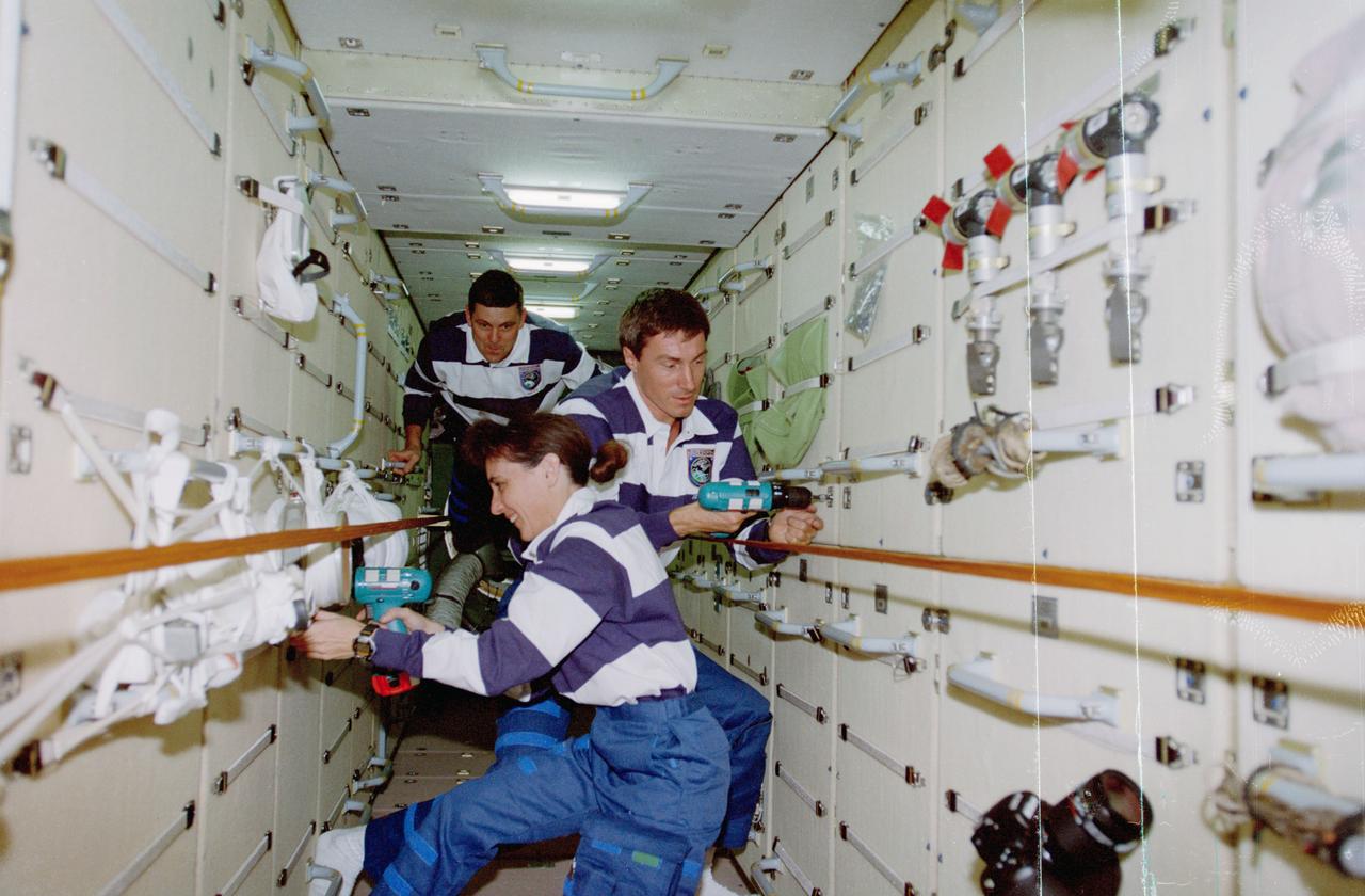
STS088-359-037 (4-15 Dec. 1998) --- Astronaut Nancy J. Currie and cosmonaut Sergei K. Krikalev, both mission specialists, use rechargeable power tools to manipulate nuts and bolts on the Russian-built Zarya module. Astronaut Robert D. Cabana, mission commander, translates along the rail network in the background. The six STS-88 crew members had earlier entered the module through the U.S.-built Unity connecting module. Rails, straps and tools indicate the crewmembers had been working awhile when this photo was taken. Krikalev, representing the Russian Space Agency (RSA), has been assigned as a member of the three-man initial International Space Station (ISS) crew.

KENNEDY SPACE CENTER, FLA. -- In the Operations and Checkout Bldg. (O&C), an overhead crane moves the S0 truss segment toward a workstand. The S0 truss will undergo processing in the O&C during which the Canadian Mobile Transporter, power distribution system modules, a heat pipe radiator for cooling, computers, and a pair of rate gyroscopes will be installed. Four Global Positioning System antennas are already installed. A 44by 15-foot structure weighing 30,800 pounds when fully outfitted and ready for launch, the truss will be at the center of the ISS 10-truss, girderlike structure that will ultimately extend the length of a football field. Eventually the S0 truss will be attached to the U.S. Lab, "Destiny," which is scheduled to be added to the ISS in April 2000. Later, other trusses will be attached to the S0 on-orbit. The S0 truss is scheduled to be launched in the first quarter of 2001 on mission STS-108
KENNEDY SPACE CENTER, FLA. -- The Z1 Integrated Truss Segment (ITS), a major element of the STS-92 mission scheduled for launch aboard Space Shuttle Atlantis in January 1999, is lowered into its workstand for processing in KSC's Space Station Processing Facility (SSPF). The Z-1 truss supports the staged buildup of International Space Station (ISS) on this third scheduled flight for ISS. The Z1 truss allows the temporary installation of the U.S. power module to Node 1. Early in the assembly sequence, the purpose of Z1 is to provide a mounting location for Ku-band and S-band telemetry and extravehicular activity (EVA) equipment. It also provides common berthing mechanism hardcover stowage. In addition, it will assist with the execution of nonpropulsive attitude control. The truss arrived at KSC on Feb. 17 for preflight processing in the SSPF
KENNEDY SPACE CENTER, FLA. -- The Z1 Integrated Truss Segment (ITS), a major element of the STS-92 mission scheduled for launch aboard Space Shuttle Atlantis in January 1999, is lowered into its workstand for processing in KSC's Space Station Processing Facility (SSPF). The Z-1 truss supports the staged buildup of International Space Station (ISS) on this third scheduled flight for ISS. The Z1 truss allows the temporary installation of the U.S. power module to Node 1. Early in the assembly sequence, the purpose of Z1 is to provide a mounting location for Ku-band and S-band telemetry and extravehicular activity (EVA) equipment. It also provides common berthing mechanism hardcover stowage. In addition, it will assist with the execution of nonpropulsive attitude control. The truss arrived at KSC on Feb. 17 for preflight processing in the SSPF
The Joint Airlock Module for the International Space Station (ISS) awaits shipment to the Kennedy Space Center in the Space Station manufacturing facility at the Marshall Space Flight Center in Huntsville, Alabama. The Airlock includes two sections. The larger equipment lock on the left is where crews will change into and out of their spacesuits for extravehicular activities, and store spacesuits, batteries, power tools, and other supplies. The narrower crewlock from which the astronauts will exit into space for extravehicular activities, is on the right. The airlock is 18 feet long and has a mass of about 13,500 pounds. It was launched to the station aboard the Space Shuttle orbiter Atlantis (STS-104 mission) on July 12, 2001. The MSFC is playing a primary role in NASA's development, manufacturing, and operations of the ISS.
Workers in KSC's Space Station Processing Facility (SSPF) assist in removing the protective casing from the Z1 Integrated Truss Segment (ITS), a major element of the STS-92 mission scheduled for launch aboard Space Shuttle Atlantis in January 1999. The Z-1 truss supports the staged buildup of International Space Station (ISS) on this third scheduled flight for ISS. The Z1 truss allows the temporary installation of the U.S. power module to Node 1. Early in the assembly sequence, the purpose of Z1 is to provide a mounting location for Ku-band and S-band telemetry and extravehicular activity (EVA) equipment. It also provides common berthing mechanism hardcover stowage. In addition, it will assist with the execution of nonpropulsive attitude control. The truss arrived at KSC on Feb. 17 for preflight processing in the SSPF
KENNEDY SPACE CENTER, FLA. -- Inside the Operations and Checkout Bldg. (O&C), an overhead crane is centered over the S0 truss segment before lowering. The crane will move it to a workstand in the O&C where it will undergo processing. In the foreground is the protective cover just removed. During the processing, the Canadian Mobile Transporter, power distribution system modules, a heat pipe radiator for cooling, computers, and a pair of rate gyroscopes will be installed. Four Global Positioning System antennas are already installed. A 44by 15-foot structure weighing 30,800 pounds when fully outfitted and ready for launch, the truss will be at the center of the ISS 10-truss, girderlike structure that will ultimately extend the length of a football field. Eventually the S0 truss will be attached to the U.S. Lab, "Destiny," which is scheduled to be added to the ISS in April 2000. Later, other trusses will be attached to the S0 on-orbit. The S0 truss is scheduled to be launched in the first quarter of 2001 on mission STS-108
KENNEDY SPACE CENTER, FLA. -- Inside the Operations and Checkout Bldg. (O&C), an overhead crane removes the cover from the S0 truss segment beneath it. The S0 truss will undergo processing in the O&C during which the Canadian Mobile Transporter, power distribution system modules, a heat pipe radiator for cooling, computers, and a pair of rate gyroscopes will be installed. Four Global Positioning System antennas are already installed. A 44by 15-foot structure weighing 30,800 pounds when fully outfitted and ready for launch, the truss will be at the center of the ISS 10-truss, girderlike structure that will ultimately extend the length of a football field. Eventually the S0 truss will be attached to the U.S. Lab, "Destiny," which is scheduled to be added to the ISS in April 2000. Later, other trusses will be attached to the S0 on-orbit. The S0 truss is scheduled to be launched in the first quarter of 2001 on mission STS-108

KENNEDY SPACE CENTER, FLA. -- The Z1 Integrated Truss Segment (ITS), a major element of the STS-92 mission scheduled for launch aboard Space Shuttle Atlantis in January 1999, is lowered into its workstand for processing in KSC's Space Station Processing Facility (SSPF). The Z-1 truss supports the staged buildup of International Space Station (ISS) on this third scheduled flight for ISS. The Z1 truss allows the temporary installation of the U.S. power module to Node 1. Early in the assembly sequence, the purpose of Z1 is to provide a mounting location for Ku-band and S-band telemetry and extravehicular activity (EVA) equipment. It also provides common berthing mechanism hardcover stowage. In addition, it will assist with the execution of nonpropulsive attitude control. The truss arrived at KSC on Feb. 17 for preflight processing in the SSPF
KENNEDY SPACE CENTER, FLA. -- Workers in the Operations & Checkout Bldg. (O&C) look over a central component of the International Space Station (ISS), the S0 (S zero) truss. It is undergoing processing in the O&C during which the Canadian Mobile Transporter, power distribution system modules, a heat pipe radiator for cooling, computers, and a pair of rate gyroscopes are being installed. A 44by 15-foot structure weighing 30,800 pounds when fully outfitted and ready for launch, the truss will ultimately extend the length of a football field. Eventually the S0 truss will be attached to the U.S. Lab, "Destiny," which is scheduled to be added to the ISS in April 2000. Later, other trusses will be attached to the S0 on-orbit. The S0 truss is scheduled to be launched in the spring of 2001
KENNEDY SPACE CENTER, FLA. -- The Z1 Integrated Truss Segment (ITS), a major element of the STS-92 mission scheduled for launch aboard Space Shuttle Atlantis in January 1999, is moved to its workstand for processing in KSC's Space Station Processing Facility (SSPF). The Z-1 truss supports the staged buildup of International Space Station (ISS) on this third scheduled flight for ISS. The Z1 truss allows the temporary installation of the U.S. power module to Node 1. Early in the assembly sequence, the purpose of Z1 is to provide a mounting location for Ku-band and S-band telemetry and extravehicular activity (EVA) equipment. It also provides common berthing mechanism hardcover stowage. In addition, it will assist with the execution of nonpropulsive attitude control. The truss arrived at KSC on Feb. 17 for preflight processing in the SSPF
The Z1 Integrated Truss Segment (ITS), a major element of the STS-92 mission scheduled for launch aboard Space Shuttle Atlantis in January 1999, awaits processing in KSC's Space Station Processing Facility (SSPF). The Z-1 truss supports the staged buildup of International Space Station (ISS) on this third scheduled flight for ISS. The Z1 truss allows the temporary installation of the U.S. power module to Node 1. Early in the assembly sequence, the purpose of Z1 is to provide a mounting location for Ku-band and S-band telemetry and extravehicular activity (EVA) equipment. It also provides common berthing mechanism hardcover stowage. In addition, it will assist with the execution of nonpropulsive attitude control. The truss arrived at KSC on Feb. 17 for preflight processing in the SSPF
KENNEDY SPACE CENTER, FLA. -- Workers in the O&C Bldg. watch as the S0 truss is lowered onto a workstand. The S0 truss will undergo processing in the O&C during which the Canadian Mobile Transporter, power distribution system modules, a heat pipe radiator for cooling, computers, and a pair of rate gyroscopes will be installed. Four Global Positioning System antennas are already installed. A 44by 15-foot structure weighing 30,800 pounds when fully outfitted and ready for launch, the truss will be at the center of the ISS 10-truss, girderlike structure that will ultimately extend the length of a football field. Eventually the S0 truss will be attached to the U.S. Lab, "Destiny," which is scheduled to be added to the ISS in April 2000. Later, other trusses will be attached to the S0 on-orbit. The S0 truss is scheduled to be launched in the first quarter of 2001 on mission STS-108
KENNEDY SPACE CENTER, FLA. -- Inside the Operations and Checkout Bldg. (O&C), workers (at left) watch over the maneuvering of the overhead crane toward the S0 truss segment below it. The S0 truss will undergo processing in the O&C during which the Canadian Mobile Transporter, power distribution system modules, a heat pipe radiator for cooling, computers, and a pair of rate gyroscopes will be installed. Four Global Positioning System antennas are already installed. A 44by 15-foot structure weighing 30,800 pounds when fully outfitted and ready for launch, the truss will be at the center of the ISS 10-truss, girderlike structure that will ultimately extend the length of a football field. Eventually the S0 truss will be attached to the U.S. Lab, "Destiny," which is scheduled to be added to the ISS in April 2000. Later, other trusses will be attached to the S0 on-orbit. The S0 truss is scheduled to be launched in the first quarter of 2001 on mission STS-108
KENNEDY SPACE CENTER, FLA. -- In the Operations and Checkout Bldg. (O&C), an overhead crane moves the S0 truss segment toward a workstand. The S0 truss will undergo processing in the O&C during which the Canadian Mobile Transporter, power distribution system modules, a heat pipe radiator for cooling, computers and a pair of rate gyroscopes will be installed. Four Global Positioning System antennas are already installed. A 44- by 15-foot structure weighing 30,800 pounds when fully outfitted and ready for launch, the truss will be at the center of the ISS 10-truss, girderlike structure that will ultimately extend the length of a football field. Eventually the S0 truss will be attached to the U.S. Lab, "Destiny," which is scheduled to be added to the ISS in April 2000. Later, other trusses will be attached to the S0 on orbit. The S0 truss is scheduled to be launched in the first quarter of 2001 on mission STS-108

STS111-E-5132 (9 June 2002) --- Astronaut Franklin R. Chang-Diaz, STS-111 mission specialist, anchored to the foot restraint at the end of the International Space Station’s (ISS) Canadarm2, participates in the first scheduled session of extravehicular activity (EVA) for the STS-111 mission. During the spacewalk, Chang-Diaz and Perrin attached a Power and Data Grapple Fixture onto the International Space Station’s (ISS) P6 Truss, setting the stage for the future relocation of the P6. The next major task was to remove Service Module Debris Panels from Space Shuttle Endeavour’s payload bay and attach them to their temporary location on Pressurized Mating Adapter 1 (PMA-1). The spacewalkers also removed thermal blankets to prepare the Mobile Base System (MBS) for installation onto the station’s Mobile Transporter (MT).
KENNEDY SPACE CENTER, FLA. -- The S0 truss nears its resting place in the workstand in the O&C Bldg. (O&C). The S0 truss will undergo processing in the O&C during which the Canadian Mobile Transporter, power distribution system modules, a heat pipe radiator for cooling, computers, and a pair of rate gyroscopes will be installed. Four Global Positioning System antennas are already installed. A 44by 15-foot structure weighing 30,800 pounds when fully outfitted and ready for launch, the truss will be at the center of the ISS 10-truss, girderlike structure that will ultimately extend the length of a football field. Eventually the S0 truss will be attached to the U.S. Lab, "Destiny," which is scheduled to be added to the ISS in April 2000. Later, other trusses will be attached to the S0 on-orbit. The S0 truss is scheduled to be launched in the first quarter of 2001 on mission STS-108

KENNEDY SPACE CENTER, FLA. -- The Z1 Integrated Truss Segment (ITS), a major element of the STS-92 mission scheduled for launch aboard Space Shuttle Atlantis in January 1999, is moved toward its workstand for processing in KSC's Space Station Processing Facility (SSPF). The Z-1 truss supports the staged buildup of International Space Station (ISS) on this third scheduled flight for ISS. The Z1 truss allows the temporary installation of the U.S. power module to Node 1. Early in the assembly sequence, the purpose of Z1 is to provide a mounting location for Ku-band and S-band telemetry and extravehicular activity (EVA) equipment. It also provides common berthing mechanism hardcover stowage. In addition, it will assist with the execution of nonpropulsive attitude control. The truss arrived at KSC on Feb. 17 for preflight processing in the SSPF
KENNEDY SPACE CENTER, FLA. -- The Z1 Integrated Truss Segment (ITS), a major element of the STS-92 mission scheduled for launch aboard Space Shuttle Atlantis in January 1999, is lowered into its workstand for processing in KSC's Space Station Processing Facility (SSPF). The Z-1 truss supports the staged buildup of International Space Station (ISS) on this third scheduled flight for ISS. The Z1 truss allows the temporary installation of the U.S. power module to Node 1. Early in the assembly sequence, the purpose of Z1 is to provide a mounting location for Ku-band and S-band telemetry and extravehicular activity (EVA) equipment. It also provides common berthing mechanism hardcover stowage. In addition, it will assist with the execution of nonpropulsive attitude control. The truss arrived at KSC on Feb. 17 for preflight processing in the SSPF
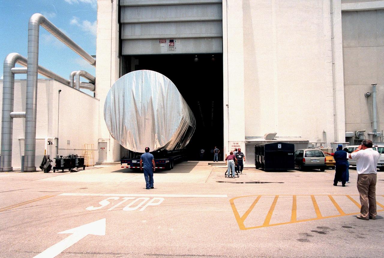
KENNEDY SPACE CENTER, FLA. -- The S0 truss segment is moved into the Operations and Checkout Bldg. (O&C) for processing. The truss arrived at the SLF aboard a "Super Guppy" aircraft from Boeing in Huntington, Calif. During processing in the O&C, the S0 truss will have installed the Canadian Mobile Transporter, power distribution system modules, a heat pipe radiator for cooling, computers, and a pair of rate gyroscopes. Four Global Positioning System antennas are already installed. A 44by 15-foot structure weighing 30,800 pounds when fully outfitted and ready for launch, the truss will be at the center of the ISS 10-truss, girderlike structure that will ultimately extend the length of a football field. Eventually the S0 truss will be attached to the U.S. Lab, "Destiny," which is scheduled to be added to the ISS in April 2000. Later, other trusses will be attached to the S0 on-orbit. The S0 truss is scheduled to be launched in the first quarter of 2001 on mission STS-108
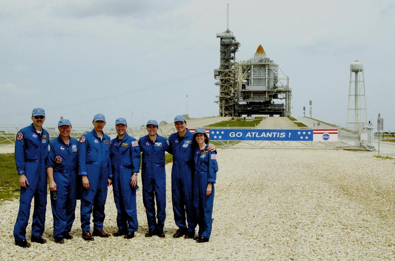
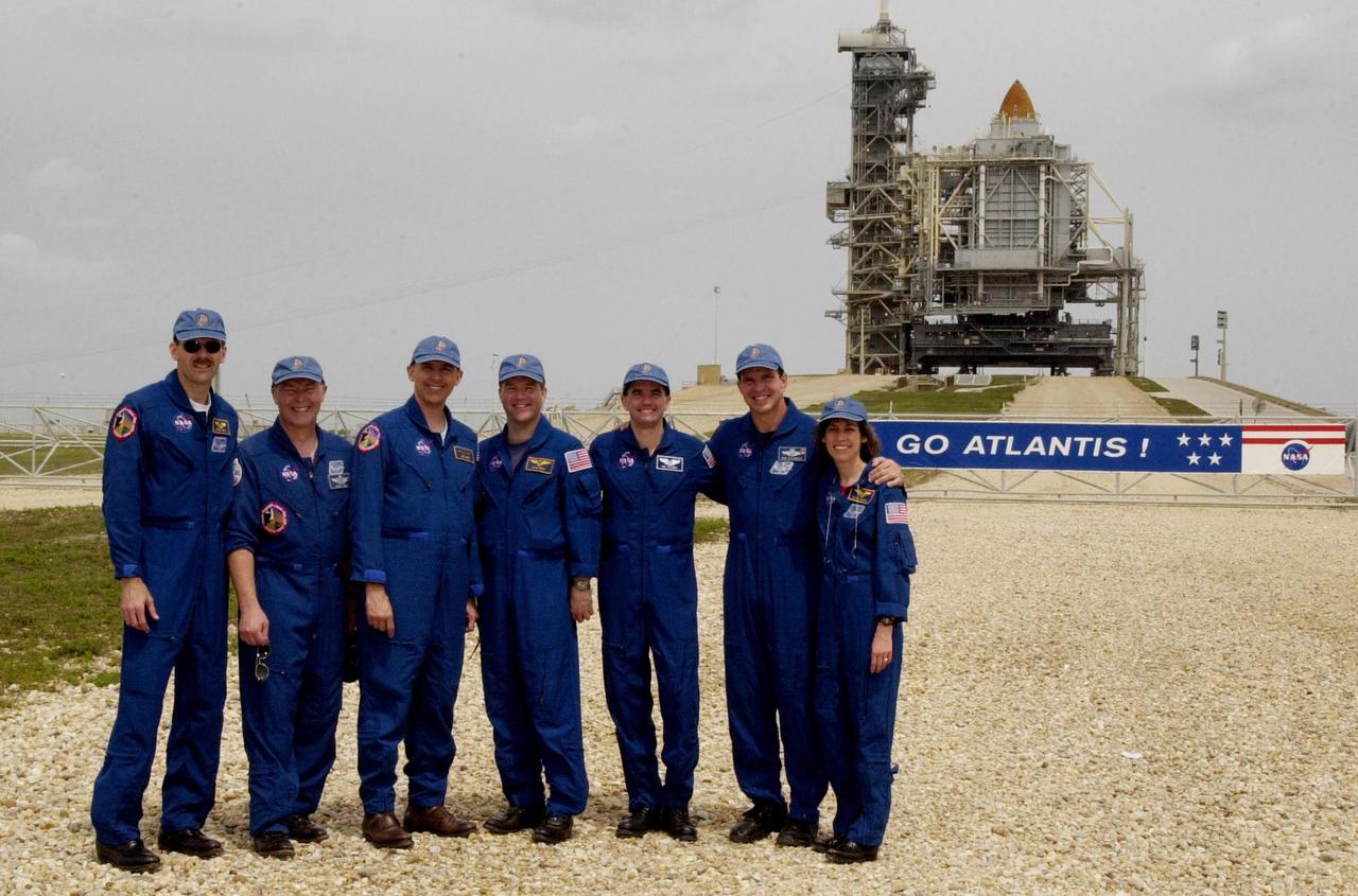
KENNEDY SPACE CENTER, FLA. -- While gathering with friends and family at the pad, the STS-110 crew poses in front of Space Shuttle Atlantis still enclosed by the Rotating Service Structure. Standing left to right are Mission Specialist Steven Smith, Jerry Ross and Lee Morin; Pilot Stephen Frick; Mission Specialist Rex Walheim; Commander Michael Bloomfield; and Mission Specialist Ellen Ochoa. The mission continues the expansion of the International Space Station by delivering and installing the S0 Integrated Truss Structure, the initial section of a framework that will eventually hold the power and cooling systems needed for future international research laboratories. The payload also comprises the Canadian Mobile Transporter (attached to the S0 truss), power distribution system modules, a heat pipe radiator for cooling, computers and a pair of rate gyroscopes. The 11-day mission is the 13th assembly flight to the ISS and includes four spacewalks to attach the S0 truss to the U.S. Lab Destiny. Launch is scheduled for April 4
KENNEDY SPACE CENTER, FLA. -- While gathering with friends and family at the pad, the STS-110 crew poses in front of Space Shuttle Atlantis still enclosed by the Rotating Service Structure. Standing left to right are Mission Specialist Steven Smith, Jerry Ross and Lee Morin; Pilot Stephen Frick; Mission Specialist Rex Walheim; Commander Michael Bloomfield; and Mission Specialist Ellen Ochoa. The mission continues the expansion of the International Space Station by delivering and installing the S0 Integrated Truss Structure, the initial section of a framework that will eventually hold the power and cooling systems needed for future international research laboratories. The payload also comprises the Canadian Mobile Transporter (attached to the S0 truss), power distribution system modules, a heat pipe radiator for cooling, computers and a pair of rate gyroscopes. The 11-day mission is the 13th assembly flight to the ISS and includes four spacewalks to attach the S0 truss to the U.S. Lab Destiny. Launch is scheduled for April 4
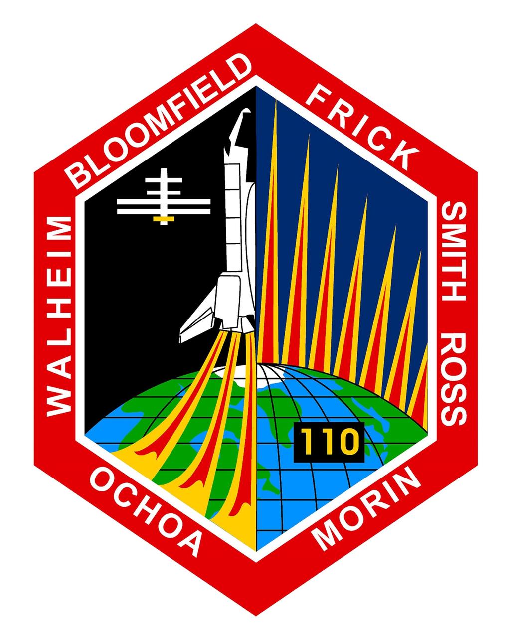
JOHNSON SPACE CENTER, HOUSTON, TEXAS. -- STS-110 INSIGNIA: The STS-110 mission begins the third and final phase of construction for the International Space Station (ISS) by delivering and installing the S0 truss segment that will be carried into orbit in the payload bay of Space Shuttle Atlantis. The Station's robotic arm will remove the S0 segment from the Shuttle's payload bay and place it on top of the United States Laboratory. During several spacewalks, S0 will be mechanically attached to ISS, and then multiple cables will be connected allowing electrical power and communications to flow between S0 and ISS. The STS-110 crew patch is patterned after the cross-section of the S0 truss, and encases the launch of the Shuttle Atlantis and a silhouette of the ISS as it will look following mission completion. The successfully installed S0 segment is highlighted in gold. The S0 truss will serve as the cornerstone for the remaining ISS truss segments, which together will span a distance greater than the length of a football field. This truss holds the Station's massive solar arrays, providing electrical power for the modules of all the International Partners, and enables the ISS to reach its full potential as a world-class research facility. The NASA insignia design for Space Shuttle flights is reserved for use by the astronauts and for other official use as the NASA Administrator may authorize. Public availability has been approved onlly in the form of illustrations by the various news media. When and if there is any change in this policy, which we do not anticipate, it will be publicly announced
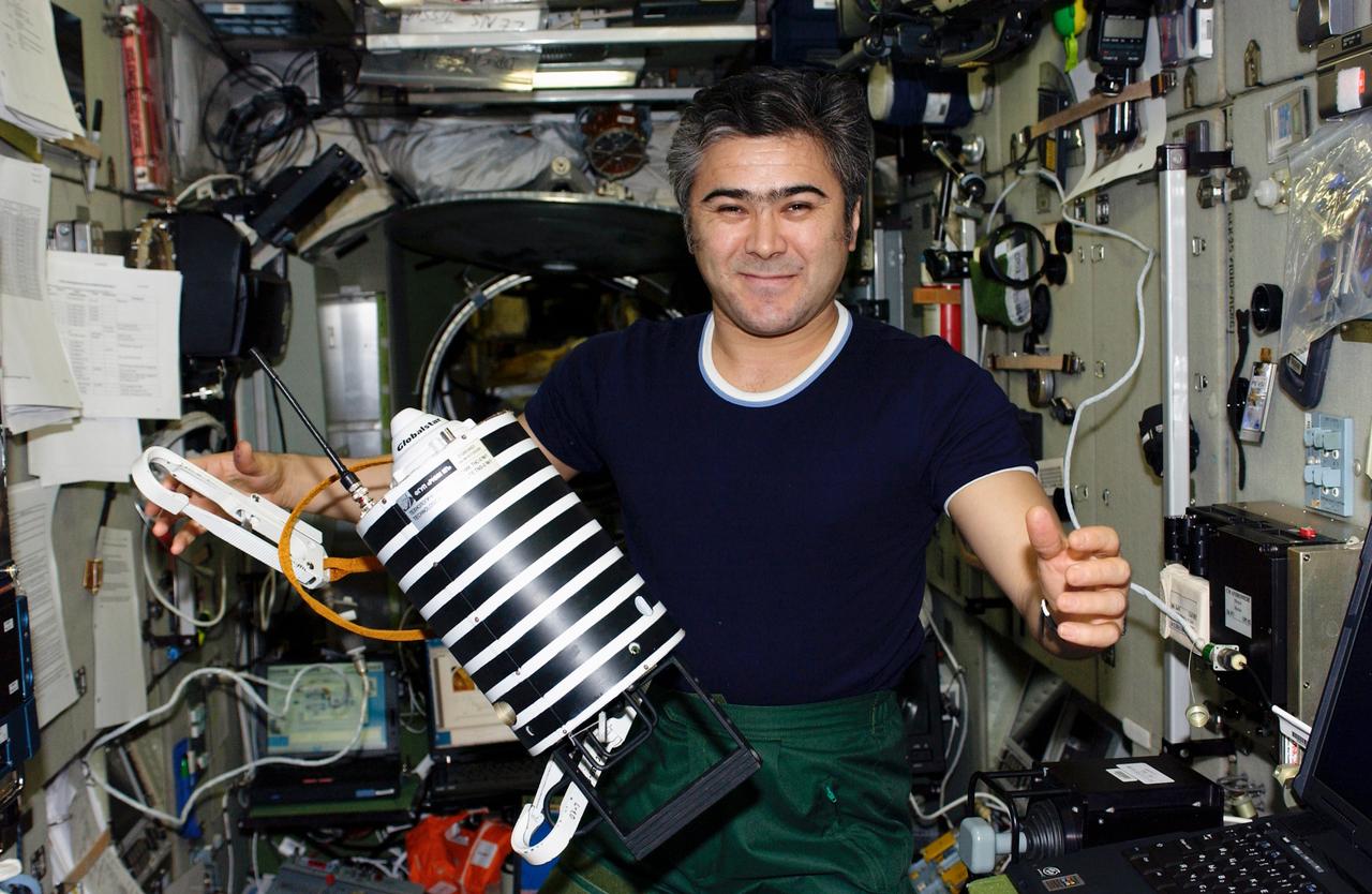
ISS010-E-20722 (21 March 2005) --- Cosmonaut Salizhan S. Sharipov, Expedition 10 flight engineer representing Russia's Federal Space Agency, holds “Nanosputnik” (TEKh-42) in the Zvezda Service Module of the International Space Station (ISS). This small (5 kilogram mass) satellite, powered by 10 lithium thionyl chloride batteries, will be activated by Sharipov after his egress from the Pirs Docking Compartment and later “launched” into its own orbit during the spacewalk scheduled for March 28. The purpose of Nanosputnik is to support development of satellite control techniques, monitoring of satellite operations, and research on new attitude system sensors and other components.
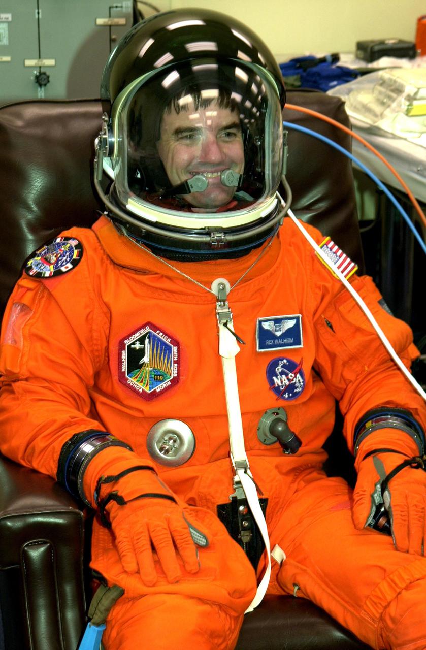
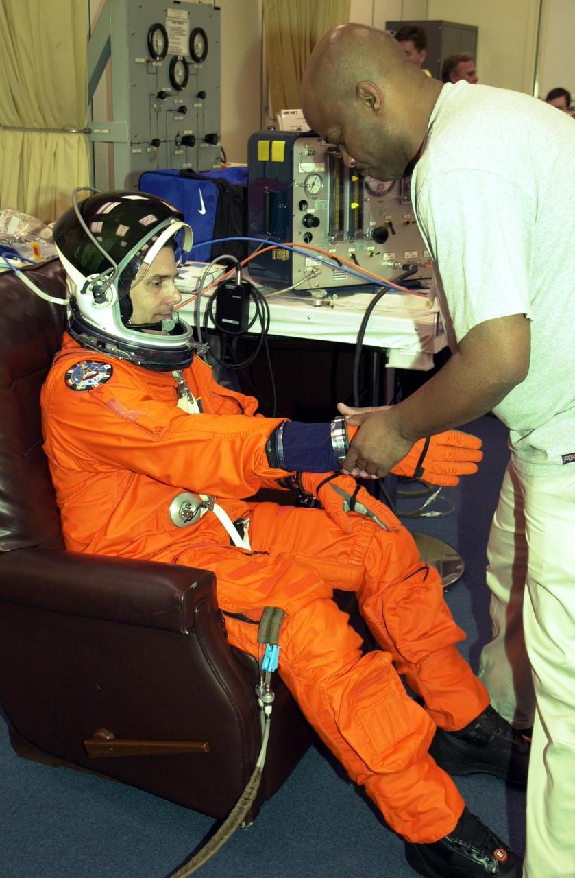
KENNEDY SPACE CENTER, FLA. -- STS-110 Mission Specialist Rex Walheim rests comfortably in his launch and entry suit during final suit check. This will be his first Shuttle flight. The STS-110 payload includes the S0 Integrated Truss Structure (ITS), the Canadian Mobile Transporter, power distribution system modules, a heat pipe radiator for cooling, computers and a pair of rate gyroscopes. The 11-day mission is the 13th assembly flight to the ISS and includes four spacewalks to attach the S0 truss to the U.S. Lab Destiny. Launch is scheduled for April 4
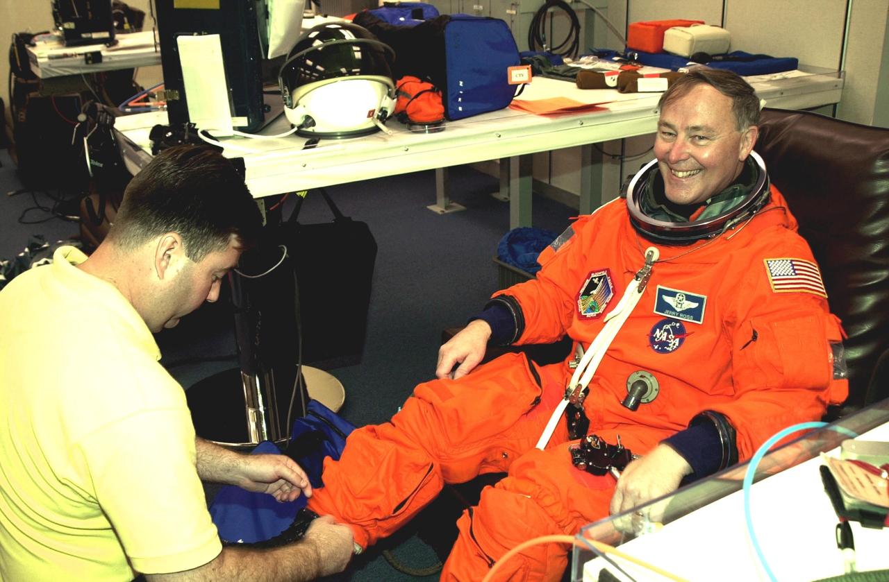
KENNEDY SPACE CENTER, FLA. -- As he undergoes a final check on his launch and entry suit, STS-110 Mission Specialist Jerry Ross shows his delight in the upcoming launch. Ross will be making a record-breaking seventh Shuttle flight. The STS-110 payload includes the S0 Integrated Truss Structure (ITS), the Canadian Mobile Transporter, power distribution system modules, a heat pipe radiator for cooling, computers and a pair of rate gyroscopes. The 11-day mission is the 13th assembly flight to the ISS and includes four spacewalks to attach the S0 truss to the U.S. Lab Destiny. Launch is scheduled for April 4
KENNEDY SPACE CENTER, FLA. -- STS-110 Mission Specialist Lee Morin undergoes final check of his launch and entry suit. Morin will be taking his first Shuttle flight. The STS-110 payload includes the S0 Integrated Truss Structure (ITS), the Canadian Mobile Transporter, power distribution system modules, a heat pipe radiator for cooling, computers and a pair of rate gyroscopes. The 11-day mission is the 13th assembly flight to the ISS and includes four spacewalks to attach the S0 truss to the U.S. Lab Destiny. Launch is scheduled for April 4

Still suspended by a crane and cables in the Space Station Processing Facility, yet hidden by the top of the Z1 integrated truss structure, the Passive Common Berthing Mechanism (PCBM) is lowered onto the truss for attachment. Workers at the top of a workstand guide it into place. A component of the International Space Station (ISS), the Z1 truss will be used for the temporary installation of the P6 truss segment to the Unity connecting module. The P6 truss segment contains the solar arrays and batteries which will provide early station power. The truss is scheduled to be launched aboard STS-92 in late 1999
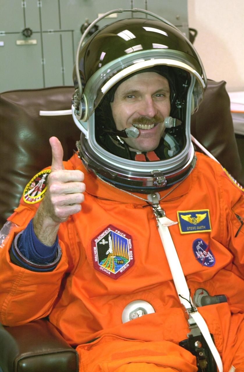
KENNEDY SPACE CENTER, FLA. -- STS-110 Mission Specialist Steven Smith gives a thumbs up for launch as he has a final check of his launch and entry suit. This flight will be his fourth. The STS-110 payload includes the S0 Integrated Truss Structure (ITS), the Canadian Mobile Transporter, power distribution system modules, a heat pipe radiator for cooling, computers and a pair of rate gyroscopes. The 11-day mission is the 13th assembly flight to the ISS and includes four spacewalks to attach the S0 truss to the U.S. Lab Destiny. Launch is scheduled for April 4
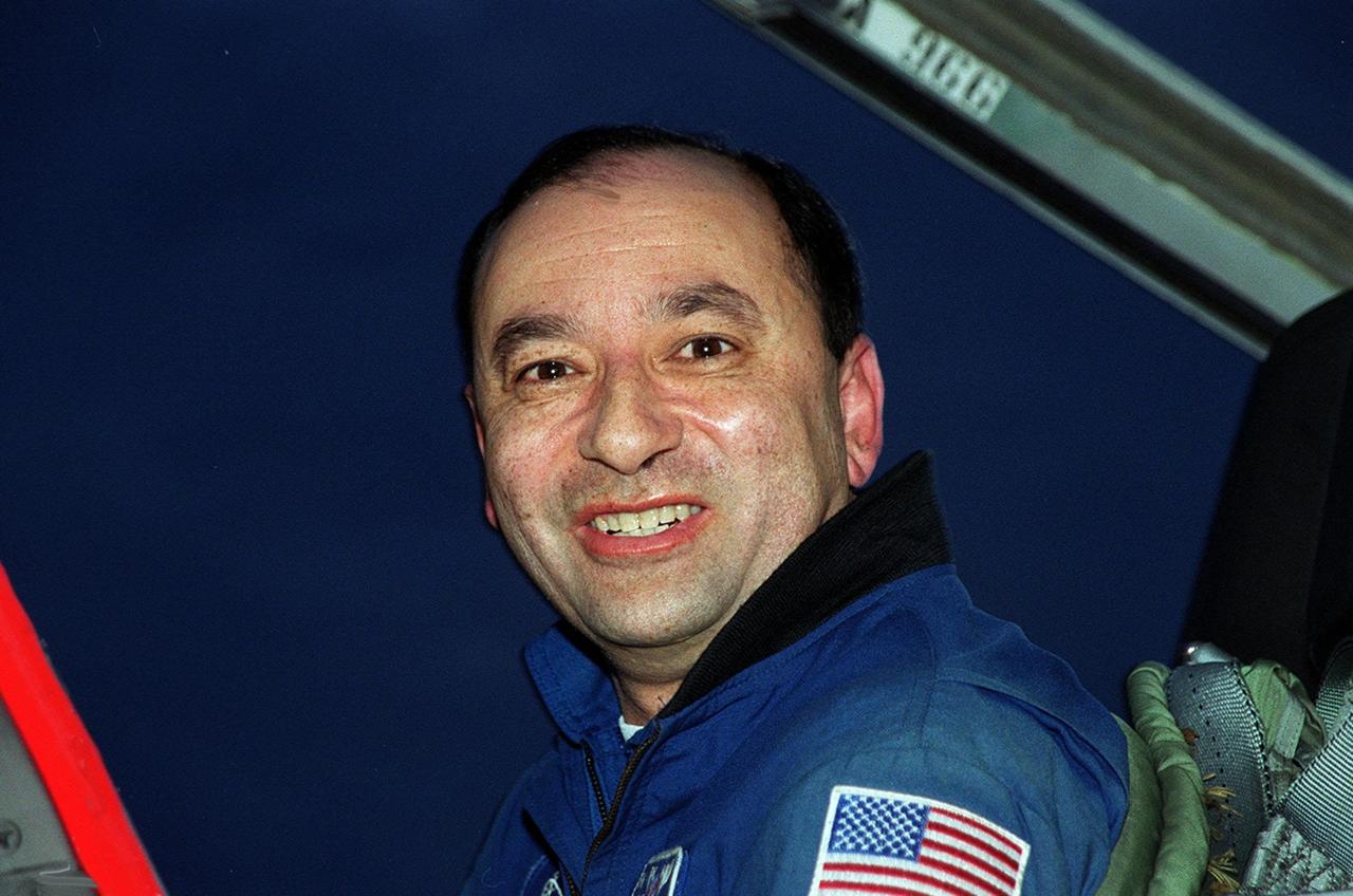
STS-98 Pilot Mark Polansky is pleased to arrive at KSC’s Shuttle Landing Facility for Terminal Countdown Test Activities. In preparation for the Jan. 19 launch, he and the rest of the crew Commander Ken Cockrell and Mission Specialists Robert Curbeam, Thomas Jones and Marsha Ivins will be training in emergency procedures from the pad, checking the payload and taking part in a simulated countdown. The payload for the mission is the U.S. Lab Destiny, a key element in the construction of the International Space Station. The lab has five system racks already installed inside the module. After delivery of electronics in the lab, electrically powered attitude control for Control Moment Gyroscopes will be activated. STS-98 is the seventh construction flight to the ISS.<br

STS-98 Pilot Mark Polansky is pleased to arrive at KSC’s Shuttle Landing Facility for Terminal Countdown Test Activities. In preparation for the Jan. 19 launch, he and the rest of the crew Commander Ken Cockrell and Mission Specialists Robert Curbeam, Thomas Jones and Marsha Ivins will be training in emergency procedures from the pad, checking the payload and taking part in a simulated countdown. The payload for the mission is the U.S. Lab Destiny, a key element in the construction of the International Space Station. The lab has five system racks already installed inside the module. After delivery of electronics in the lab, electrically powered attitude control for Control Moment Gyroscopes will be activated. STS-98 is the seventh construction flight to the ISS.<br
STS-102 astronaut and mission specialist James S. Voss works outside Destiny, the U.S. Laboratory (shown in lower frame) on the International Space Station (ISS), while anchored to the Remote Manipulator System (RMS) robotic arm on the Space Shuttle Discovery during the first of two space walks. During this space walk, the longest to date in space shuttle history, Voss in tandem with Susan Helms (out of frame), prepared the Pressurized Mating Adapter 3 for repositioning from the Unity Module's Earth-facing berth to its port-side berth to make room for the Leonardo Multipurpose Logistics Module (MPLM) supplied by the Italian Space Agency. The The Leonardo MPLM is the first of three such pressurized modules that will serve as the ISS' moving vans, carrying laboratory racks filled with equipment, experiments, and supplies to and from the Station aboard the Space Shuttle. The cylindrical module is approximately 21-feet long and 15- feet in diameter, weighing almost 4.5 tons. It can carry up to 10 tons of cargo in 16 standard Space Station equipment racks. Of the 16 racks the module can carry, 5 can be furnished with power, data, and fluid to support refrigerators or freezers. In order to function as an attached station module as well as a cargo transport, the logistics module also includes components that provide life support, fire detection and suppression, electrical distribution, and computer functions. Launched on May 8, 2001 for nearly 13 days in space, the STS-102 mission was the 8th spacecraft assembly flight to the ISS and NASA's 103rd overall mission. The mission also served as a crew rotation flight. It delivered the Expedition Two crew to the Station and returned the Expedition One crew back to Earth.
STS-102 mission astronaut Susan J. Helms works outside the International Space Station (ISS) while holding onto a rigid umbilical and her feet anchored to the Remote Manipulator System (RMS) robotic arm on the Space Shuttle Discovery during the first of two space walks. During this space walk, the longest to date in space shuttle history, Helms in tandem with James S. Voss (out of frame), prepared the Pressurized Mating Adapter 3 for repositioning from the Unity Module's Earth-facing berth to its port-side berth to make room for the Leonardo Multipurpose Logistics Module (MPLM) supplied by the Italian Space Agency. The Leonardo MPLM is the first of three such pressurized modules that will serve as the ISS's moving vans, carrying laboratory racks filled with equipment, experiments, and supplies to and from the Station aboard the Space Shuttle. The cylindrical module is approximately 21-feet long and 15- feet in diameter, weighing almost 4.5 tons. It can carry up to 10 tons of cargo in 16 standard Space Station equipment racks. Of the 16 racks the module can carry, 5 can be furnished with power, data, and fluid to support refrigerators or freezers. In order to function as an attached station module as well as a cargo transport, the logistics module also includes components that provide life support, fire detection and suppression, electrical distribution, and computer functions. Launched on May 8, 2001 for nearly 13 days in space, STS-102 mission was the 8th spacecraft assembly flight to the ISS and NASA's 103rd overall mission. The mission also served as a crew rotation flight. It delivered the Expedition Two crew to the Station and returned the Expedition One crew back to Earth.
KENNEDY SPACE CENTER, FLA. -- In the Space Station Processing Facility, STS-88 Mission Specialists Sergei Krikalev (left), a Russian cosmonaut; James H. Newman (center); and Jerry L. Ross conduct a sharp-edge inspection of the Unity connecting module, which is the primary payload on their upcoming mission. The STS-88 crew members are participating in a Crew Equipment Interface Test (CEIT), familiarizing themselves with the orbiter's midbody and crew compartments. Targeted for liftoff on Dec. 3, 1998, STS-88 will be the first Space Shuttle launch for assembly of the International Space Station (ISS). The primary payload is the Unity connecting module which will be mated to the Russian-built Zarya control module, expected to be already on orbit after a November launch from Russia. The first major U.S.-built component of ISS, Unity will serve as a connecting passageway to living and working areas of the space station. Unity has two attached pressurized mating adapters (PMAs) and one stowage rack installed inside. PMA-1 provides the permanent connection point between Unity and Zarya; PMA-2 will serve as a Space Shuttle docking port. Zarya is a self-supporting active vehicle, providing propulsive control capability and power during the early assembly stages. It also has fuel storage capability
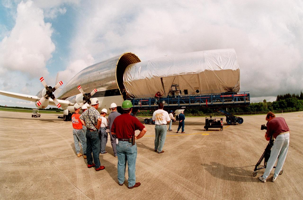
KENNEDY SPACE CENTER, FLA. -- At KSC's Shuttle Landing Facility, workers watch as a S0 (S Zero) truss segment built for the International Space Station (ISS) is moved out of the "Super Guppy" aircraft that brought it to KSC from Boeing in Huntington Beach, Calif. At right a cameraman records the exercise. The truss segment, which will become the backbone of the orbiting ISS, is a 44by 15-foot structure weighing 30,800 pounds when fully outfitted and ready for launch. It will be at the center of the ISS 10-truss, girderlike structure that will ultimately extend the length of a football field. Eventually the S0 truss will be attached to the U.S. Lab, "Destiny," which is scheduled to be added to the ISS in April 2000. Later, other trusses will be attached to the S0 on-orbit. During processing at KSC, the Canadian Mobile Transporter will be installed on the S0 truss, followed by power distribution system modules, a heat pipe radiator for cooling, computers, and a pair of rate gyroscopes. Four Global Positioning System antennas are already installed. The S0 truss is scheduled to be launched in the first quarter of 2001 on mission STS-108

Five NASA astronauts and two cosmonauts representing the Russian Aviation and Space Agency take a break in training from their scheduled September 2000 visit to the International Space Station (ISS). Astronauts Terrence W. Wilcutt (right front), and Scott D. Altman (left front) are mission commander and pilot, respectively. On the back row (from the left) are mission specialists Boris V. Morukov, cosmonaut, along with astronauts Richard A. Mastracchio, Edward T. Lu, and Daniel C. Burbank, and cosmonaut Yuri I. Malenchenko. Morukov and Malenchenko represent the Russian Aviation and Space Agency. Launched aboard the Space Shuttle Atlantis on September 8, 2000 at 7:46 a.m. (CDT), the STS-106 crew successfully prepared the International Space Station (ISS) for occupancy. Acting as plumbers, movers, installers and electricians, they installed batteries, power converters, a toilet and a treadmill on the outpost. They also delivered more than 2,993 kilograms (6,600 pounds) of supplies. Lu and Malenchenko performed a space walk to connect power, and data and communications cables to the newly arrived Zvezda Service Module and the Station.
STS-102 mission astronaut Susan J. Helms translates along the longerons of the Space Shuttle Discovery during the first of two space walks. During this walk, the Pressurized Mating Adapter 3 was prepared for repositioning from the Unity Module's Earth-facing berth to its port-side berth to make room for the Leonardo multipurpose Logistics Module (MPLM), supplied by the Italian Space Agency. The Leonardo MPLM is the first of three such pressurized modules that will serve as the International Space Station's (ISS') moving vans, carrying laboratory racks filled with equipment, experiments, and supplies to and from the Station aboard the Space Shuttle. The cylindrical module is approximately 21-feet long and 15- feet in diameter, weighing almost 4.5 tons. It can carry up to 10 tons of cargo in 16 standard Space Station equipment racks. Of the 16 racks the module can carry, 5 can be furnished with power, data, and fluid to support refrigerators or freezers. In order to function as an attached station module as well as a cargo transport, the logistics module also includes components that provide life support, fire detection and suppression, electrical distribution, and computer functions. NASA's 103rd overall mission and the 8th Space Station Assembly Flight, STS-102 mission also served as a crew rotation flight. It delivered the Expedition Two crew to the Station and returned the Expedition One crew back to Earth.
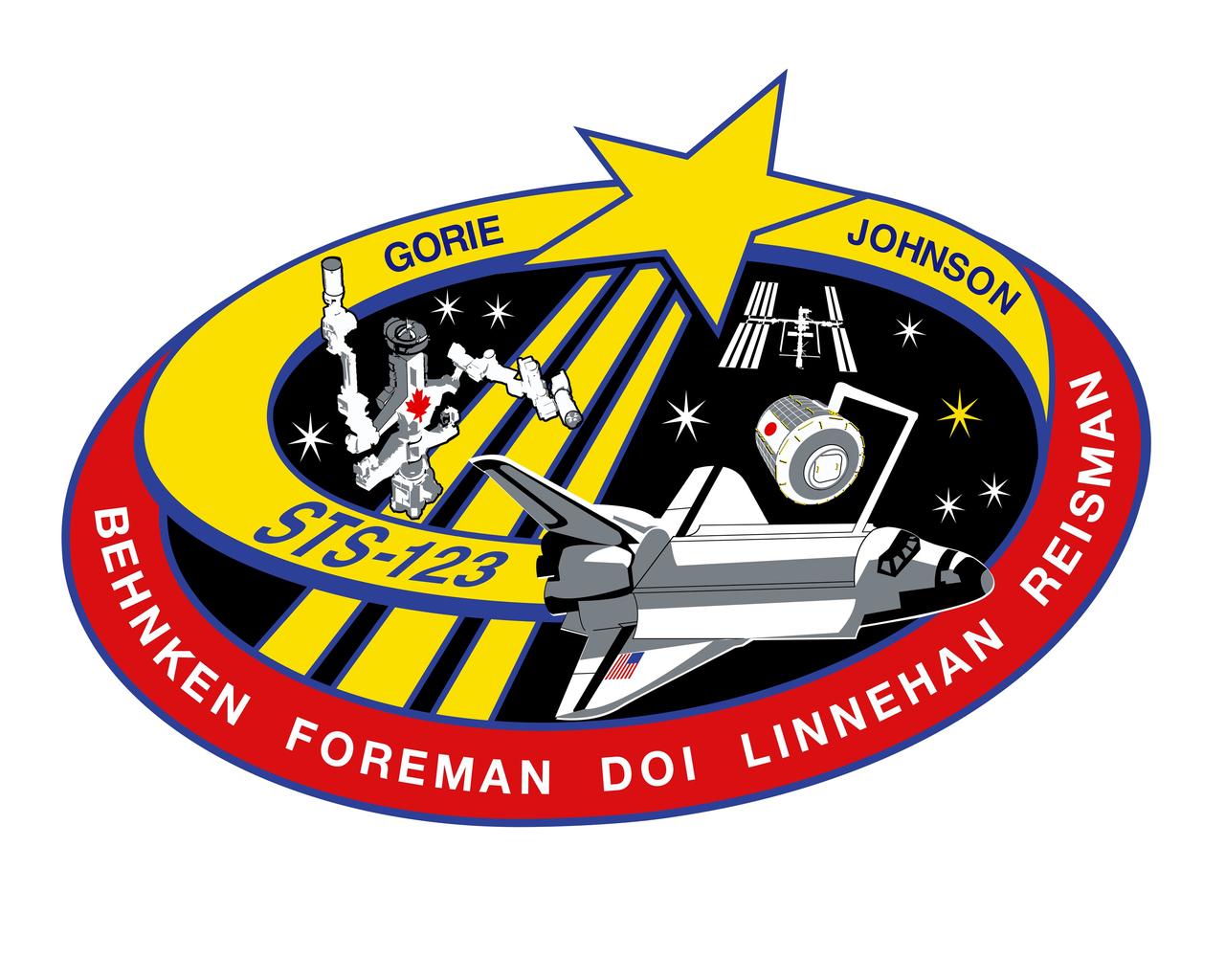
STS123-S-001 (Oct. 2007) --- STS-123 continues assembly of the International Space Station (ISS). The primary mission objectives include rotating an expedition crew member and installing both the first component of the Japanese Experimental Module (the Experimental Logistics Module - Pressurized Section (ELM-PS)) and the Canadian Special Purpose Dexterous Manipulator (SPDM). In addition, STS-123 will deliver various spare ISS components and leave behind the sensor boom used for inspecting the shuttle's thermal protection system. A follow-on mission to ISS will utilize and then return home with this sensor boom. A total of four spacewalks are planned to accomplish these tasks. The mission will also require the use of both the shuttle and ISS robotic arms. STS-123 will utilize the Station-Shuttle Power Transfer System to extend the docked portion of the mission to eleven days, with a total planned duration of 15 days. The crew patch depicts the space shuttle in orbit with the crew names trailing behind. STS-123's major additions to ISS (the ELM-PS installation with the shuttle robotic arm and the fully constructed SPDM) are both illustrated. The ISS is shown in the configuration that the STS-123 crew will encounter when they arrive. The NASA insignia design for space shuttle flights is reserved for use by the astronauts and for other official use as the NASA Administrator may authorize. Public availability has been approved only in the forms of illustrations by the various news media. When and if there is any change in this policy, which is not anticipated, the change will be publicly announced. Photo credit: NASA
![JOHNSON SPACE CENTER, HOUSTON -- STS123-S-001-- STS-123 continues assembly of the International Space Station (ISS). The primary mission objectives include rotating an expedition crew member and installing both the first component of the Japanese Experimental Module (the Experimental Logistics Module - Pressurized Section [ELM-PS]) and the Canadian Special Purpose Dexterous Manipulator (SPDM). In addition, STS-123 will deliver various spare ISS components and leave behind the sensor boom used for inspecting the shuttle's thermal protection system. A follow-on mission to ISS will utilize and then return home with this sensor boom. A total of four spacewalks are planned to accomplish these tasks. The mission will also require the use of both the shuttle and ISS robotic arms. STS-123 will utilize the Station-Shuttle Power Transfer System to extend the docked portion of the mission to 11 days, with a total planned duration of 15 days. The crew patch depicts the space shuttle in orbit with the crew names trailing behind. STS-123's major additions to ISS (the ELM-PS installation with the shuttle robotic arm and the fully constructed SPDM) are both illustrated. The ISS is shown in the configuration that the STS-123 crew will encounter when they arrive. The NASA insignia design for shuttle flights is reserved for use by the astronauts and for other official use as the NASA Administrator may authorize. Public availability has been approved only in the form of illustrations by the various news media. When and if there is any change in this policy, which is not anticipated, it will be publicly announced.](https://images-assets.nasa.gov/image/KSC-08pd0363/KSC-08pd0363~medium.jpg)
JOHNSON SPACE CENTER, HOUSTON -- STS123-S-001-- STS-123 continues assembly of the International Space Station (ISS). The primary mission objectives include rotating an expedition crew member and installing both the first component of the Japanese Experimental Module (the Experimental Logistics Module - Pressurized Section [ELM-PS]) and the Canadian Special Purpose Dexterous Manipulator (SPDM). In addition, STS-123 will deliver various spare ISS components and leave behind the sensor boom used for inspecting the shuttle's thermal protection system. A follow-on mission to ISS will utilize and then return home with this sensor boom. A total of four spacewalks are planned to accomplish these tasks. The mission will also require the use of both the shuttle and ISS robotic arms. STS-123 will utilize the Station-Shuttle Power Transfer System to extend the docked portion of the mission to 11 days, with a total planned duration of 15 days. The crew patch depicts the space shuttle in orbit with the crew names trailing behind. STS-123's major additions to ISS (the ELM-PS installation with the shuttle robotic arm and the fully constructed SPDM) are both illustrated. The ISS is shown in the configuration that the STS-123 crew will encounter when they arrive. The NASA insignia design for shuttle flights is reserved for use by the astronauts and for other official use as the NASA Administrator may authorize. Public availability has been approved only in the form of illustrations by the various news media. When and if there is any change in this policy, which is not anticipated, it will be publicly announced.
The Zvezda Service Module, the first Russian contribution and third element to the International Space Station (ISS), is shown under construction in the Krunichev State Research and Production Facility (KhSC) in Moscow. Russian technicians work on the module shortly after it completed a pressurization test. In the foreground is the forward portion of the module, including the spherical transfer compartment and its three docking ports. The forward port docked with the cornected Functional Cargo Block, followed by Node 1. Launched via a three-stage Proton rocket on July 12, 2000, the Zvezda Service Module serves as the cornerstone for early human habitation of the Station, providing living quarters, life support system, electrical power distribution, data processing system, flight control system, and propulsion system. It also provides a communications system that includes remote command capabilities from ground flight controllers. The 42,000-pound module measures 43 feet in length and has a wing span of 98 feet. Similar in layout to the core module of Russia's Mir space station, it contains 3 pressurized compartments and 13 windows that allow ultimate viewing of Earth and space.
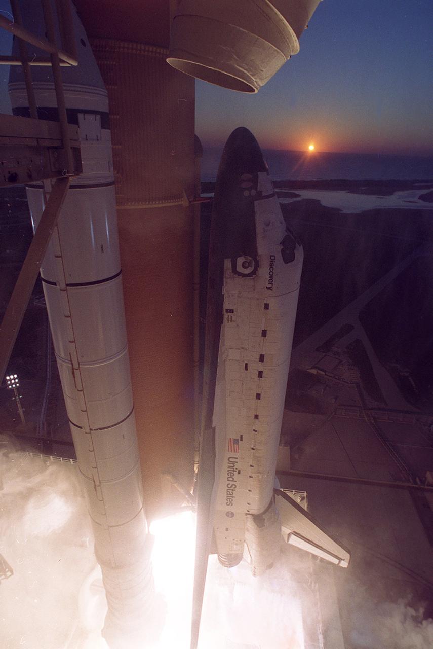
The Space Shuttle Discovery, STS-102 mission, clears launch pad 39B at the Kennedy Space Center as the sun peers over the Atlantic Ocean on March 8, 2001. STS-102's primary cargo was the Leonardo, the Italian Space Agency built Multipurpose Logistics Module (MPLM). The Leonardo MPLM is the first of three such pressurized modules that will serve as the International Space Station's (ISS') moving vans, carrying laboratory racks filled with equipment, experiments, and supplies to and from the Station aboard the Space Shuttle. The cylindrical module is approximately 21-feet long and 15- feet in diameter, weighing almost 4.5 tons. It can carry up to 10 tons of cargo in 16 standard Space Station equipment racks. Of the 16 racks the module can carry, 5 can be furnished with power, data, and fluid to support refrigerators or freezers. In order to function as an attached station module as well as a cargo transport, the logistics module also includes components that provide life support, fire detection and suppression, electrical distribution, and computer functions. NASA's 103rd overall flight and the eighth assembly flight, STS-102 was also the first flight involved with Expedition Crew rotation. The Expedition Two crew was delivered to the station while Expedition One was returned home to Earth.
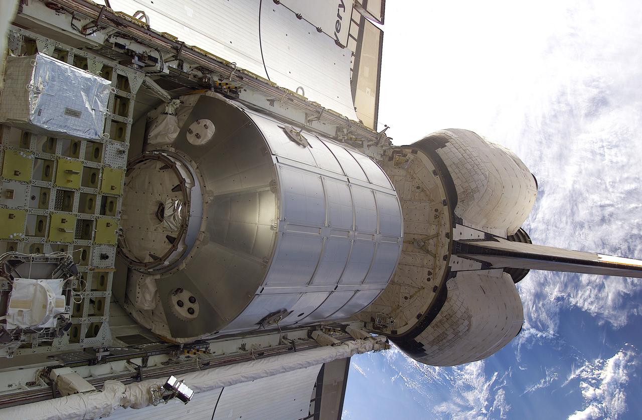
This in-orbit close up shows the Italian Space Agency-built multipurpose Logistics Module (MPLM), Leonardo, the primary cargo of the STS-102 mission, resting in the payload bay of the Space Shuttle Orbiter Discovery. The Leonardo MPLM is the first of three such pressurized modules that will serve as the International Space Station's (ISS') moving vans, carrying laboratory racks filled with equipment, experiments, and supplies to and from the Station aboard the Space Shuttle. The cylindrical module is approximately 21-feet long and 15- feet in diameter, weighing almost 4.5 tons. It can carry up to 10 tons of cargo in 16 standard Space Station equipment racks. Of the 16 racks the module can carry, 5 can be furnished with power, data, and fluid to support refrigerators or freezers. In order to function as an attached station module as well as a cargo transport, the logistics module also includes components that provide life support, fire detection and suppression, electrical distribution, and computer functions. The eighth station assembly flight and NASA's 103rd overall flight, STS-102 launched March 8, 2001 for an almost 13 day mission.
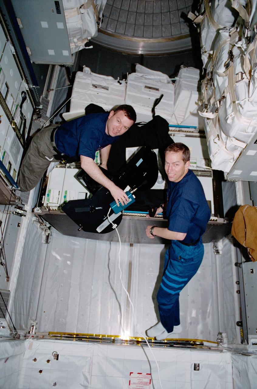
Pilot James M. Kelly (left) and Commander James D. Wetherbee for the STS-102 mission, participate in the movement of supplies inside Leonardo, the Italian Space Agency built Multipurpose Logistics Module (MPLM). In this particular photograph, the two are handling a film magazine for the IMAX cargo bay camera. The primary cargo of the STS-102 mission, the Leonardo MPLM is the first of three such pressurized modules that will serve as the International Space Station's (ISS') moving vans, carrying laboratory racks filled with equipment, experiments, and supplies to and from the Station aboard the Space Shuttle. The cylindrical module is approximately 21-feet long and 15- feet in diameter, weighing almost 4.5 tons. It can carry up to 10 tons of cargo in 16 standard Space Station equipment racks. Of the 16 racks the module can carry, 5 can be furnished with power, data, and fluid to support refrigerators or freezers. In order to function as an attached station module as well as a cargo transport, the logistics module also includes components that provide life support, fire detection and suppression, electrical distribution, and computer functions. The eighth station assembly flight, the STS-102 mission also served as a crew rotation flight. It delivered the Expedition Two crew to the Station and returned the Expedition One crew back to Earth.
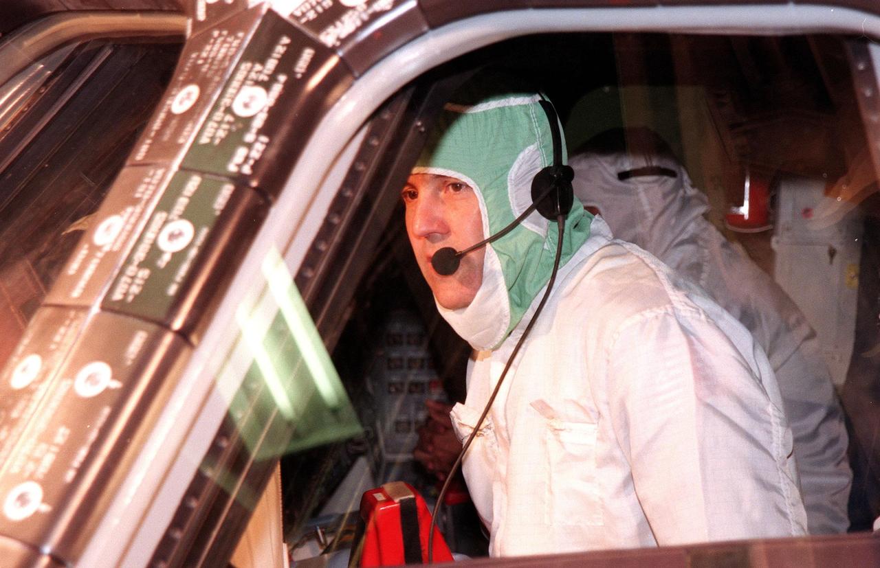
KENNEDY SPACE CENTER, FLA. -- In the Orbiter Processing Facility Bay 1, STS-88 Commander Robert D. Cabana makes a visual inspection of the windows on Space Shuttle orbiter Endeavour. The STS-88 crew members are participating in a Crew Equipment Interface Test (CEIT), familiarizing themselves with the orbiter's midbody and crew compartments. Targeted for liftoff on Dec. 3, 1998, STS-88 will be the first Space Shuttle launch for assembly of the International Space Station (ISS). The primary payload is the Unity connecting module which will be mated to the Russian-built Zarya control module, expected to be already on orbit after a November launch from Russia. The first major U.S.-built component of ISS, Unity will serve as a connecting passageway to living and working areas of the space station. Unity has two attached pressurized mating adapters (PMAs) and one stowage rack installed inside. PMA-1 provides the permanent connection point between Unity and Zarya; PMA-2 will serve as a Space Shuttle docking port. Zarya is a self-supporting active vehicle, providing propulsive control capability and power during the early assembly stages. It also has fuel storage capability
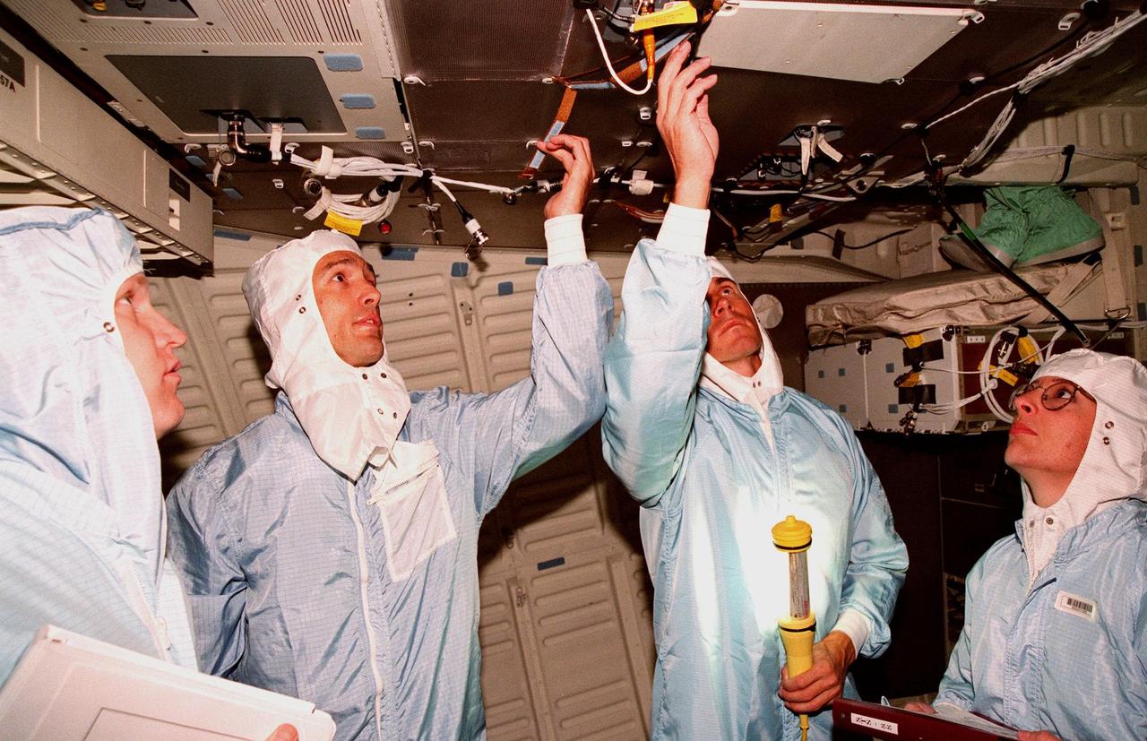
KENNEDY SPACE CENTER, FLA. -- Inside Space Shuttle orbiter Endeavour in the Orbiter Processing Facility Bay 1, workers James Neilhouse (left) and Melissa Groening (right) watch while STS-88 Mission Specialists James H. Newman (second from left) and Sergei Krikalev, a Russian cosmonaut, check overhead equipment. STS-88 crew members are participating in a Crew Equipment Interface Test (CEIT), familiarizing themselves with the orbiter's midbody and crew compartments. Targeted for liftoff on Dec. 3, 1998, STS-88 will be the first Space Shuttle launch for assembly of the International Space Station (ISS). The primary payload is the Unity connecting module which will be mated to the Russian-built Zarya control module, expected to be already on orbit after a November launch from Russia. The first major U.S.-built component of ISS, Unity will serve as a connecting passageway to living and working areas of the space station. Unity has two attached pressurized mating adapters (PMAs) and one stowage rack installed inside. PMA-1 provides the permanent connection point between Unity and Zarya; PMA-2 will serve as a Space Shuttle docking port. Zarya is a self-supporting active vehicle, providing propulsive control capability and power during the early assembly stages. It also has fuel storage capability.
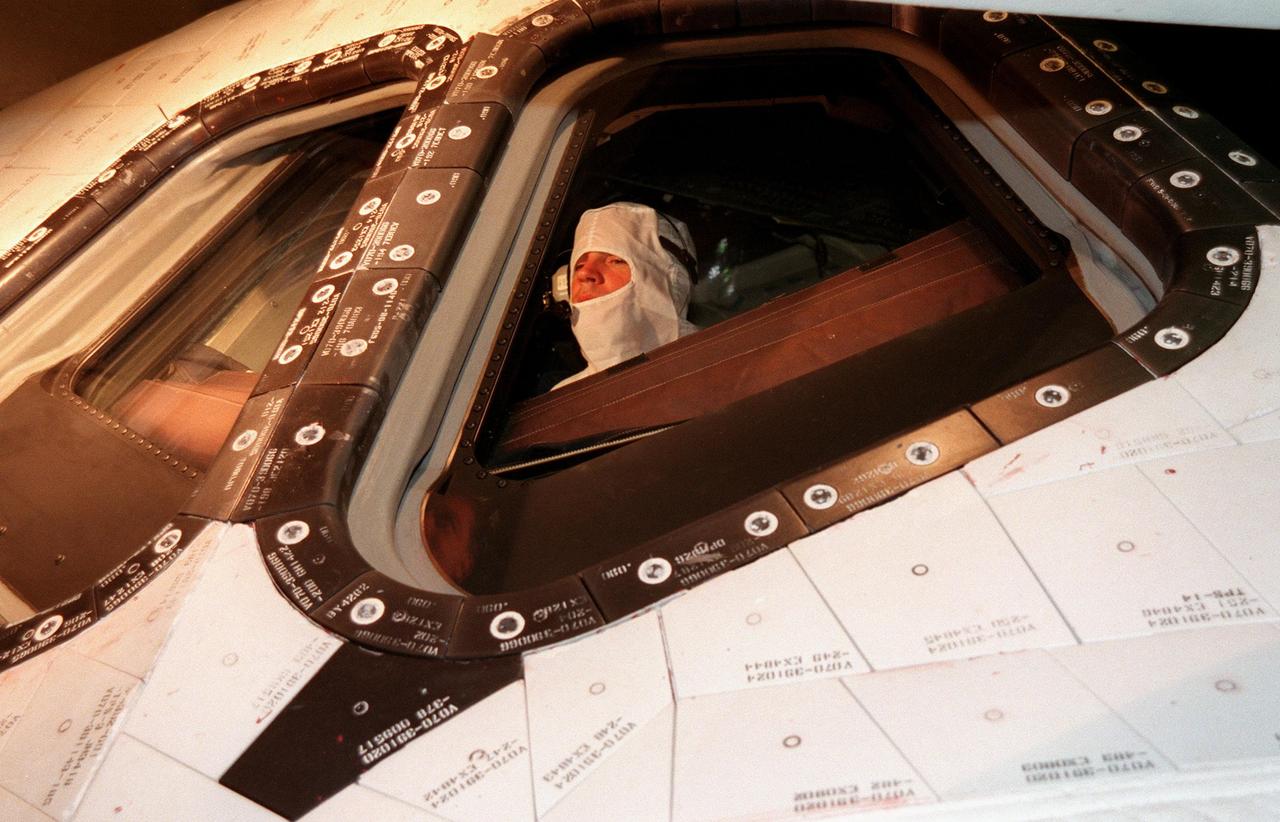
KENNEDY SPACE CENTER, FLA. -- In the Orbiter Processing Facility Bay 1, STS-88 Pilot Frederick W. Sturckow makes a visual inspection of windows on the Space Shuttle orbiter Endeavour. The STS-88 crew members are participating in a Crew Equipment Interface Test (CEIT), familiarizing themselves with the orbiter's midbody and crew compartments. Targeted for launch on Dec. 3, 1998, STS-88 will be the first Space Shuttle launch for assembly of the International Space Station (ISS). The primary payload is the Unity connecting module which will be mated to the Russian-built Zarya control module, expected to be already on orbit after a November launch from Russia. The first major U.S.-built component of ISS, Unity will serve as a connecting passageway to living and working areas of the space station. Unity has two attached pressurized mating adapters (PMAs) and one stowage rack installed inside. PMA-1 provides the permanent connection point between Unity and Zarya; PMA-2 will serve as a Space Shuttle docking port. Zarya is a self-supporting active vehicle, providing propulsive control capability and power during the early assembly stages. It also has fuel storage capability
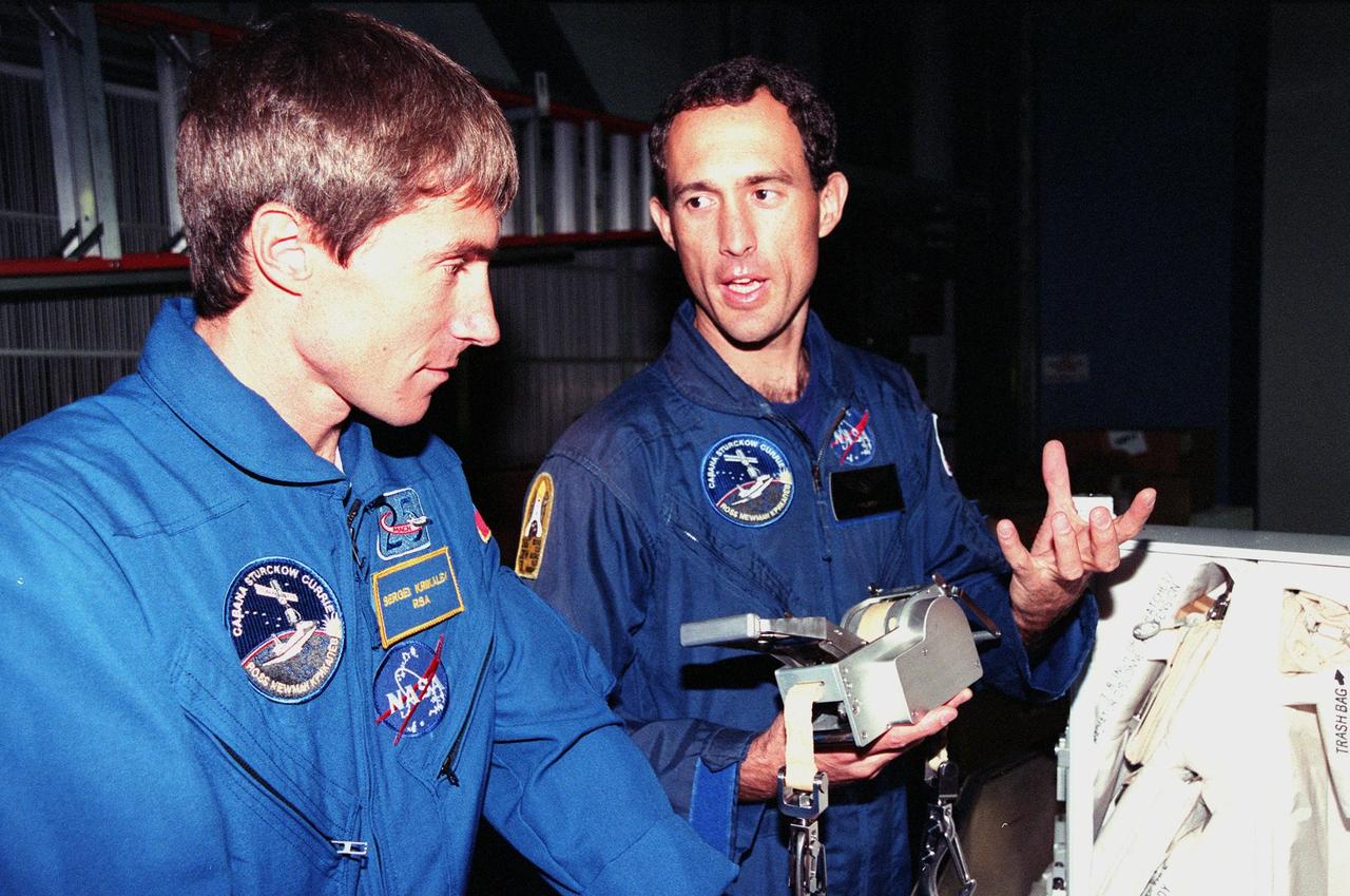
KENNEDY SPACE CENTER, FLA. -- Inside the Orbiter Processing Facility Bay 1, STS-88 Mission Specialists Sergei Krikalev (left), a Russian cosmonaut; and James H. Newman look over equipment for their upcoming flight. The STS-88 crew members are participating in a Crew Equipment Interface Test (CEIT), familiarizing themselves with the orbiter's midbody and crew compartments. Targeted for liftoff on Dec. 3, 1998, STS-88 will be the first Space Shuttle launch for assembly of the International Space Station (ISS). The primary payload is the Unity connecting module which will be mated to the Russian-built Zarya control module, expected to be already on orbit after a November launch from Russia. The first major U.S.-built component of ISS, Unity will serve as a connecting passageway to living and working areas of the space station. Unity has two attached pressurized mating adapters (PMAs) and one stowage rack installed inside. PMA-1 provides the permanent connection point between Unity and Zarya; PMA-2 will serve as a Space Shuttle docking port. Zarya is a self-supporting active vehicle, providing propulsive control capability and power during the early assembly stages. It also has fuel storage capability