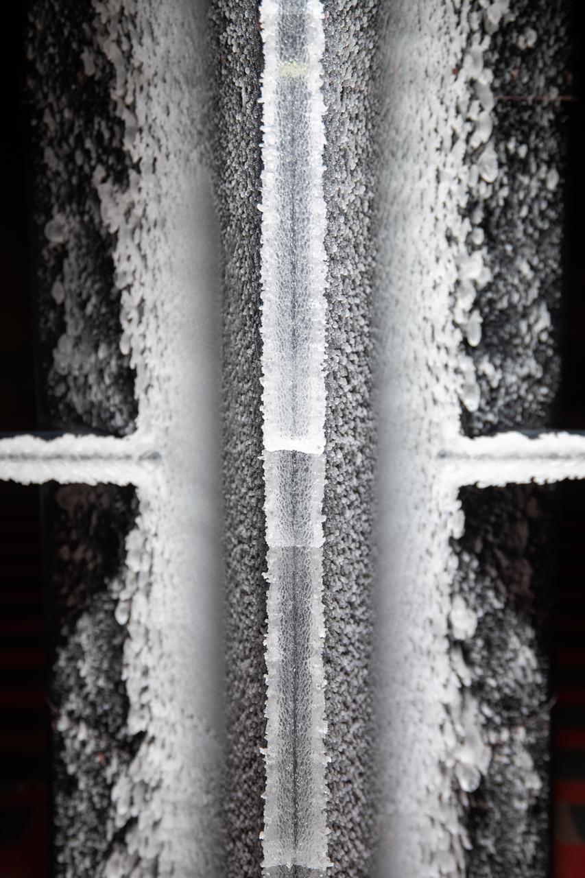
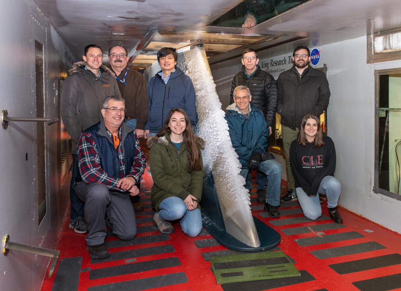
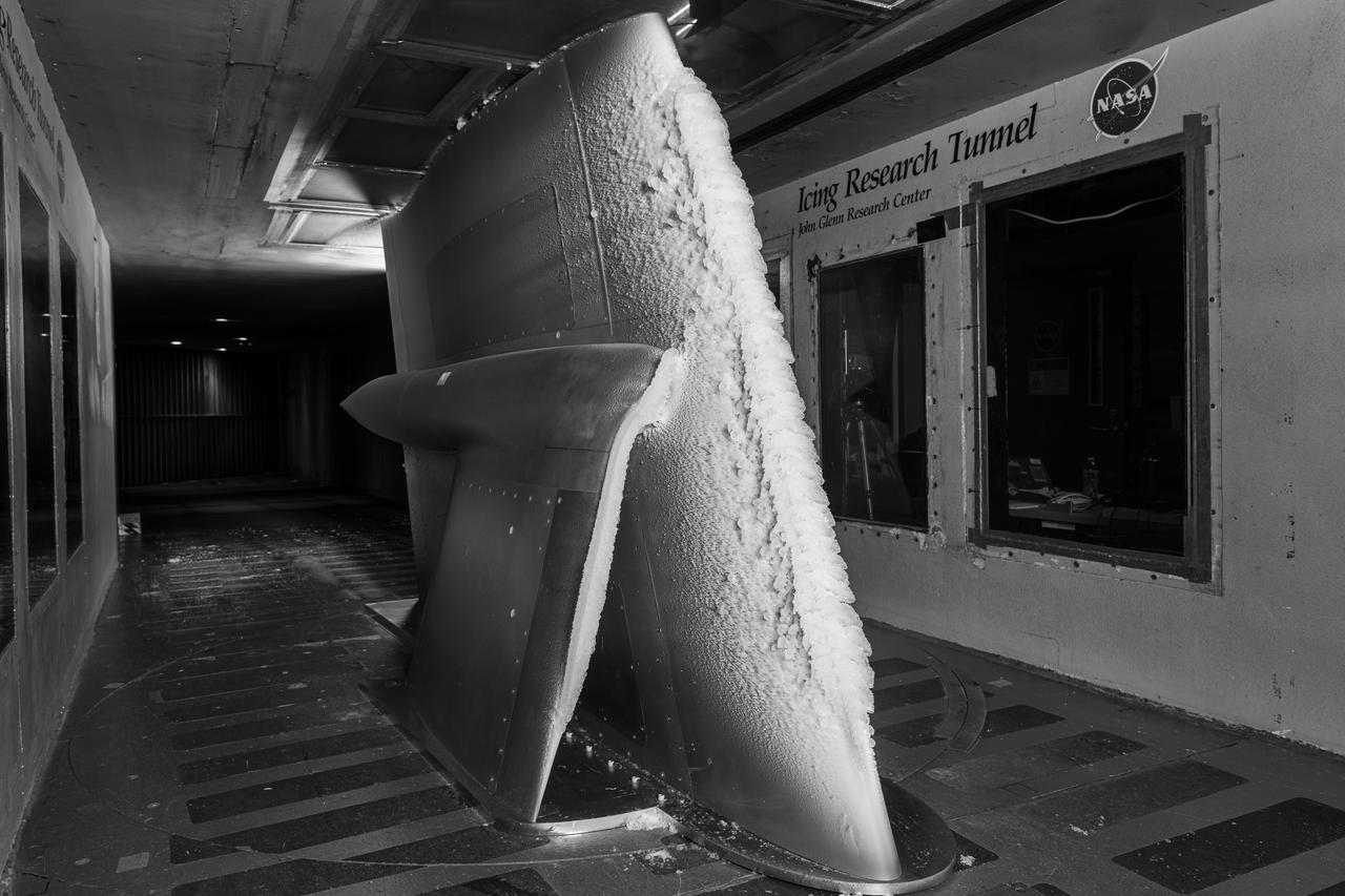
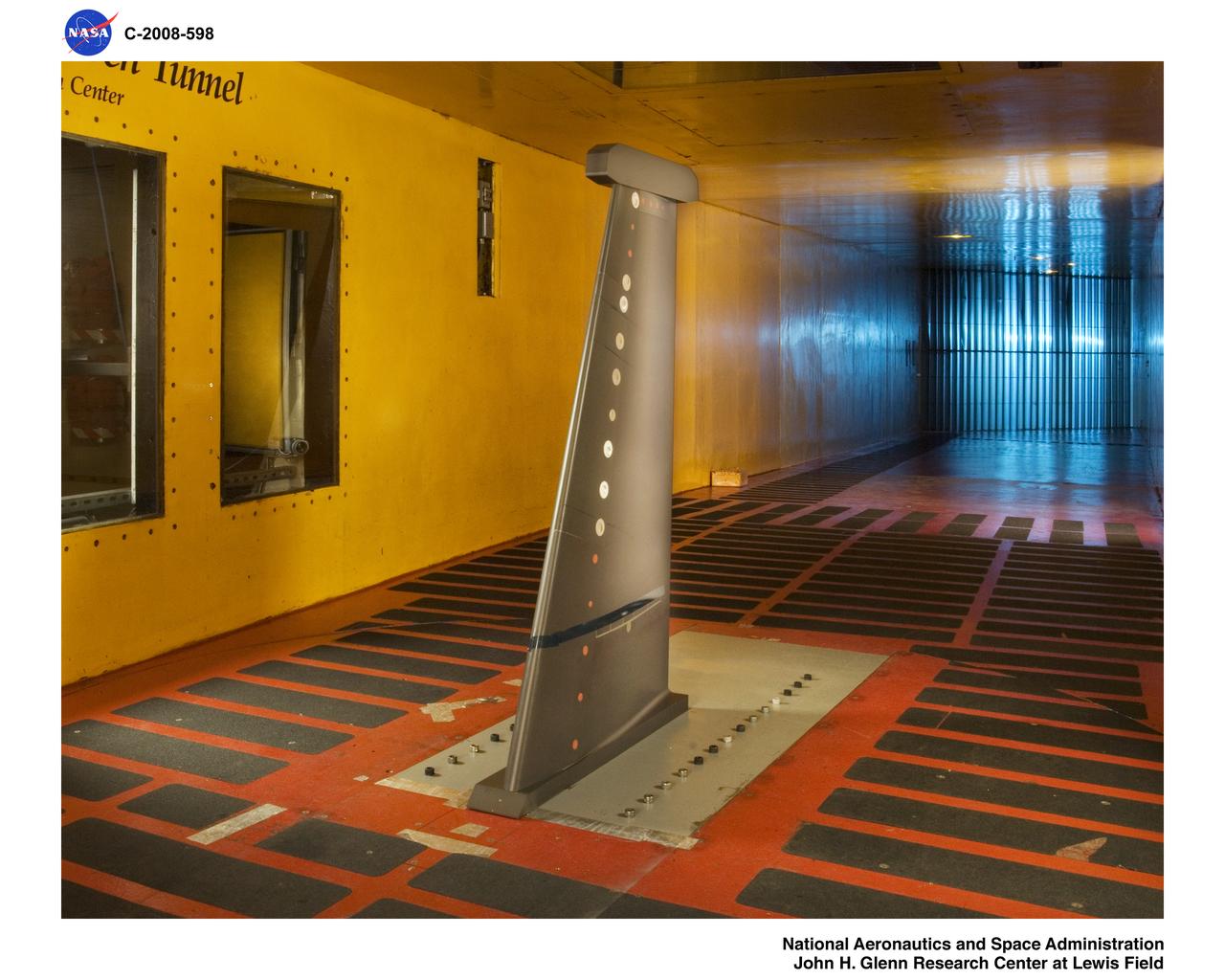
Ice built up on a test article at the at the Icing Research Tunnel as researchers study the icing physics that occur when aircraft fly through freezing weather conditions.
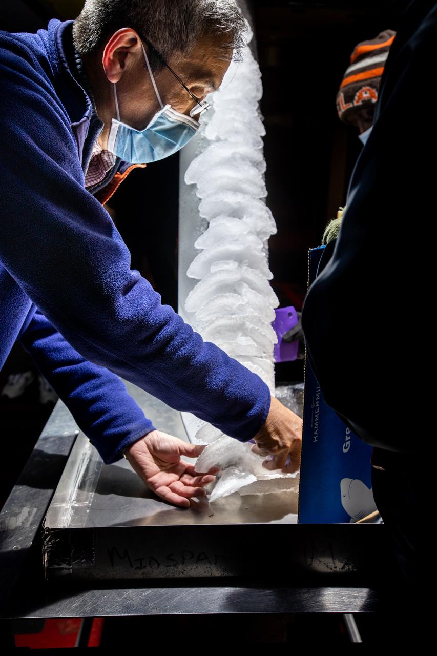
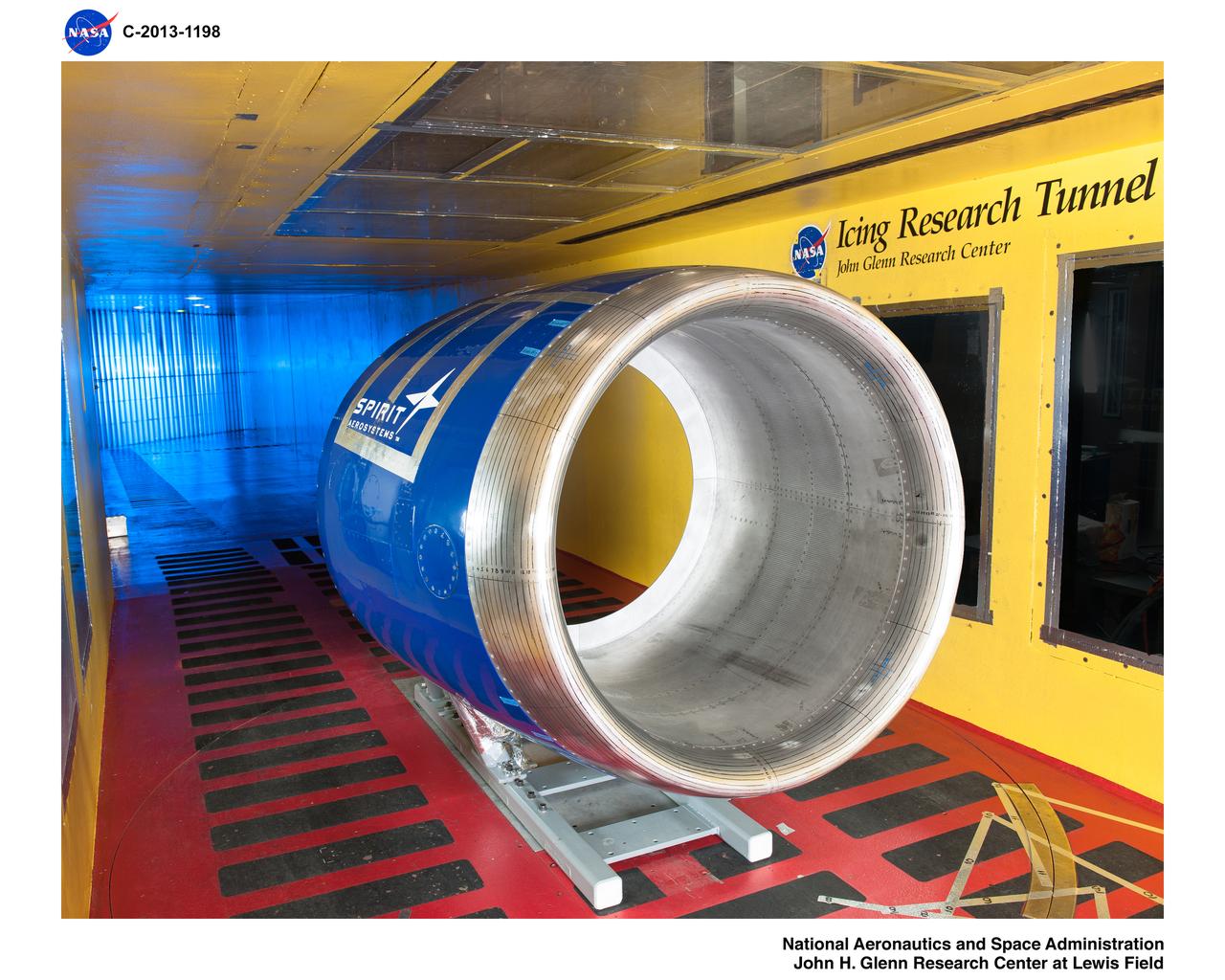
Pictured is a model to study the ice collection on struts in jet engines during flight. Researchers inspect the ice after the model encounters a simulated icing cloud during testing. Super cooled water created from the icing cloud that flows though the wind tunnel. The super cooled water forms ice on contact with the test model. Researchers then inspect the ice formation before laser scanning of the ice formation for further research and analysis.
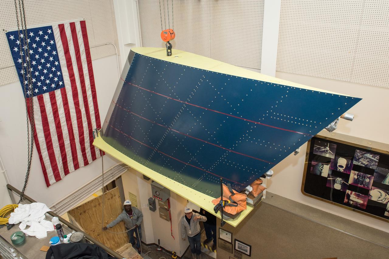
CRM Full Chord Installation and Test Documentation Photos, Icing Research Tunnel
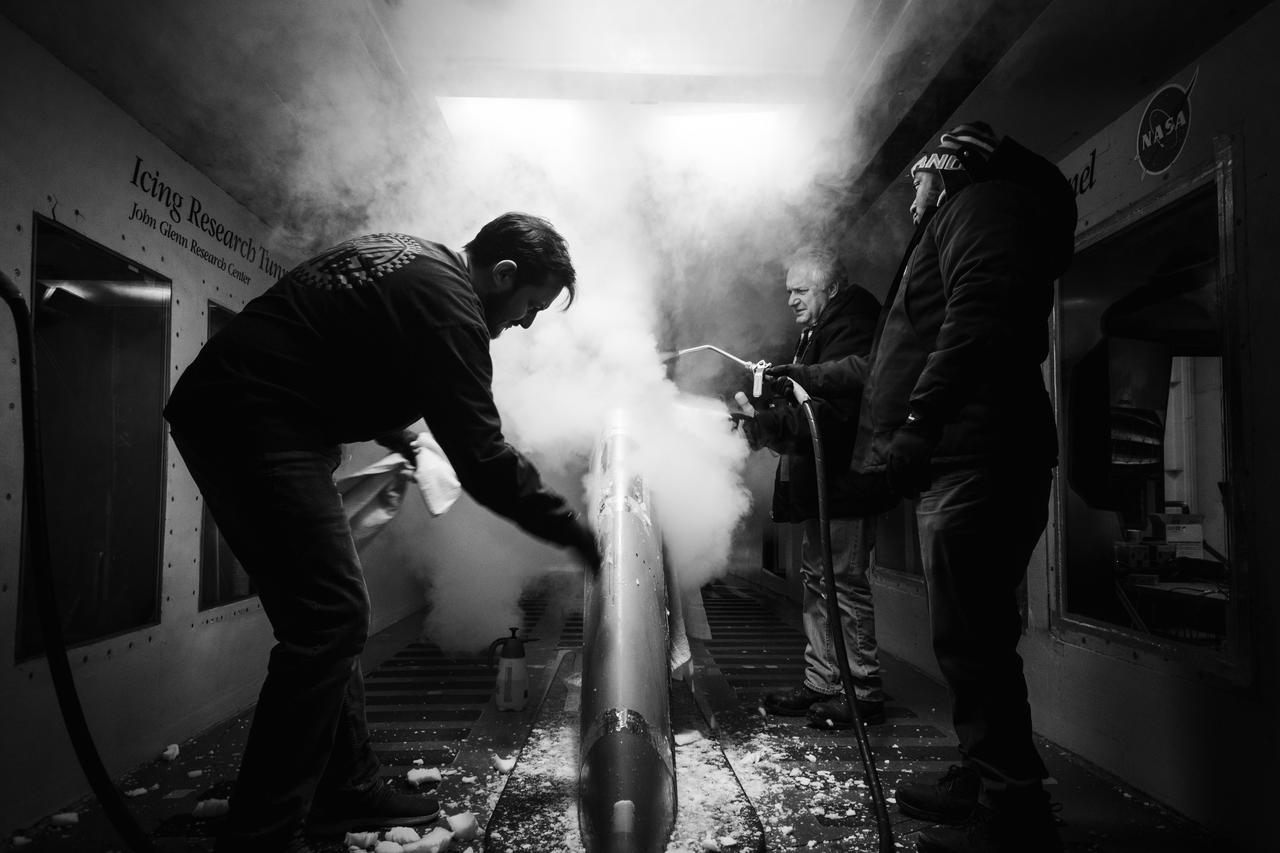
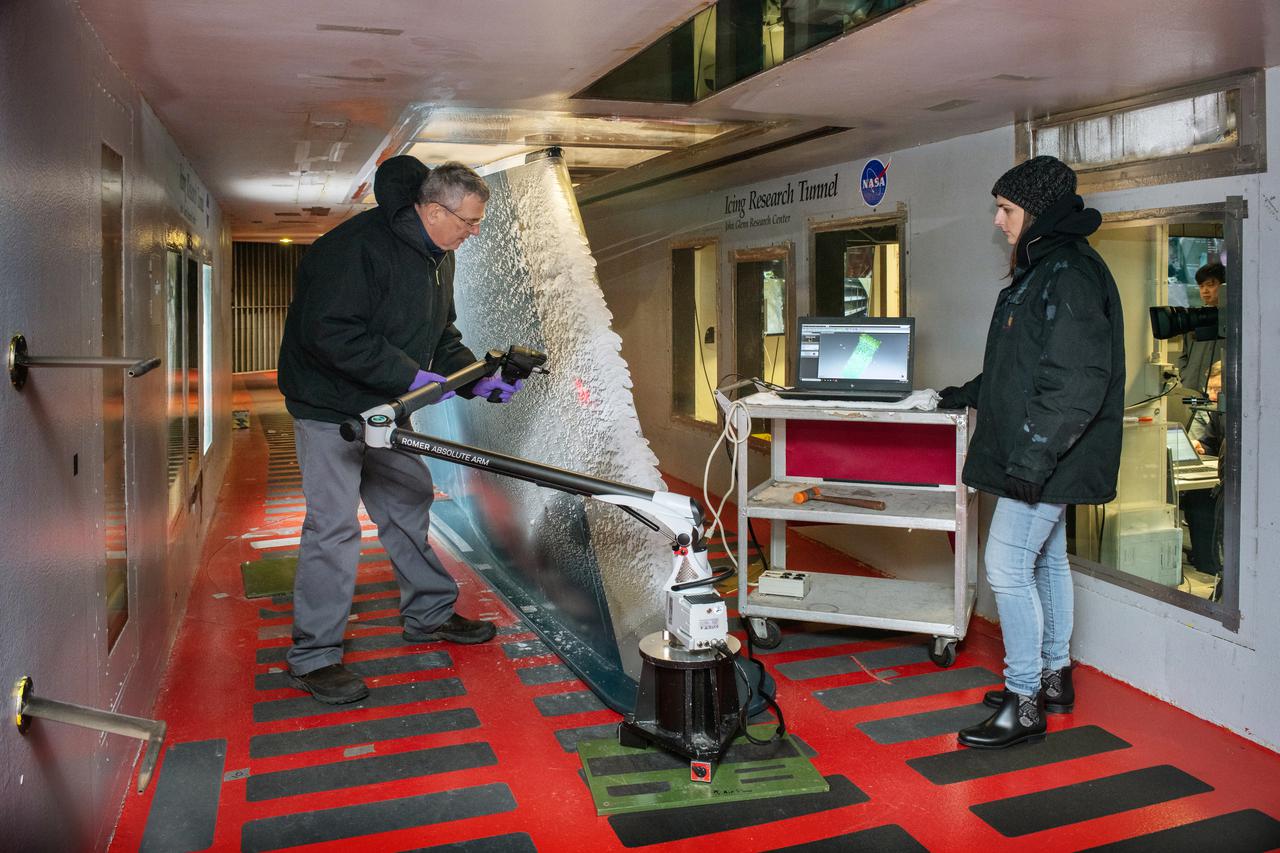
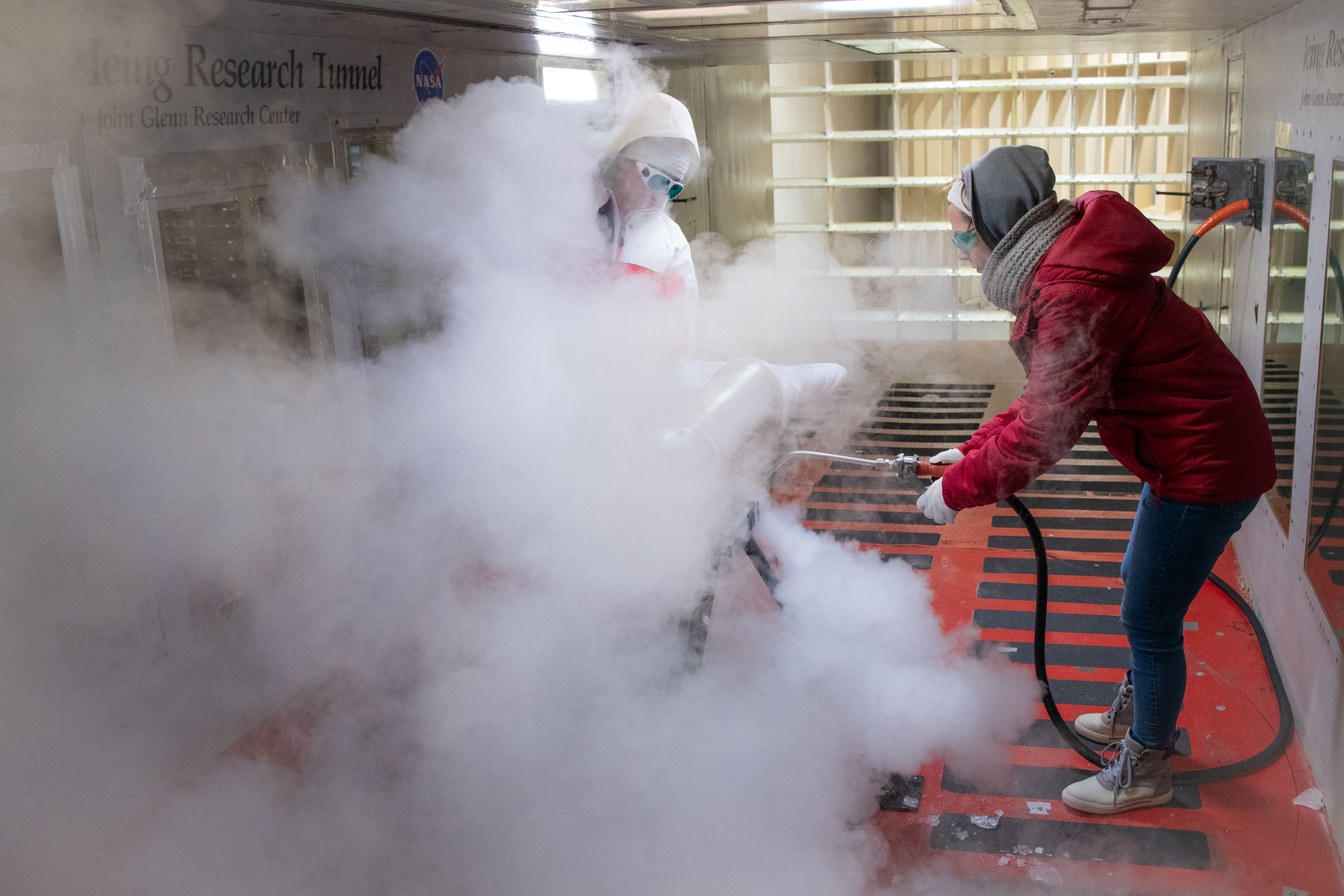
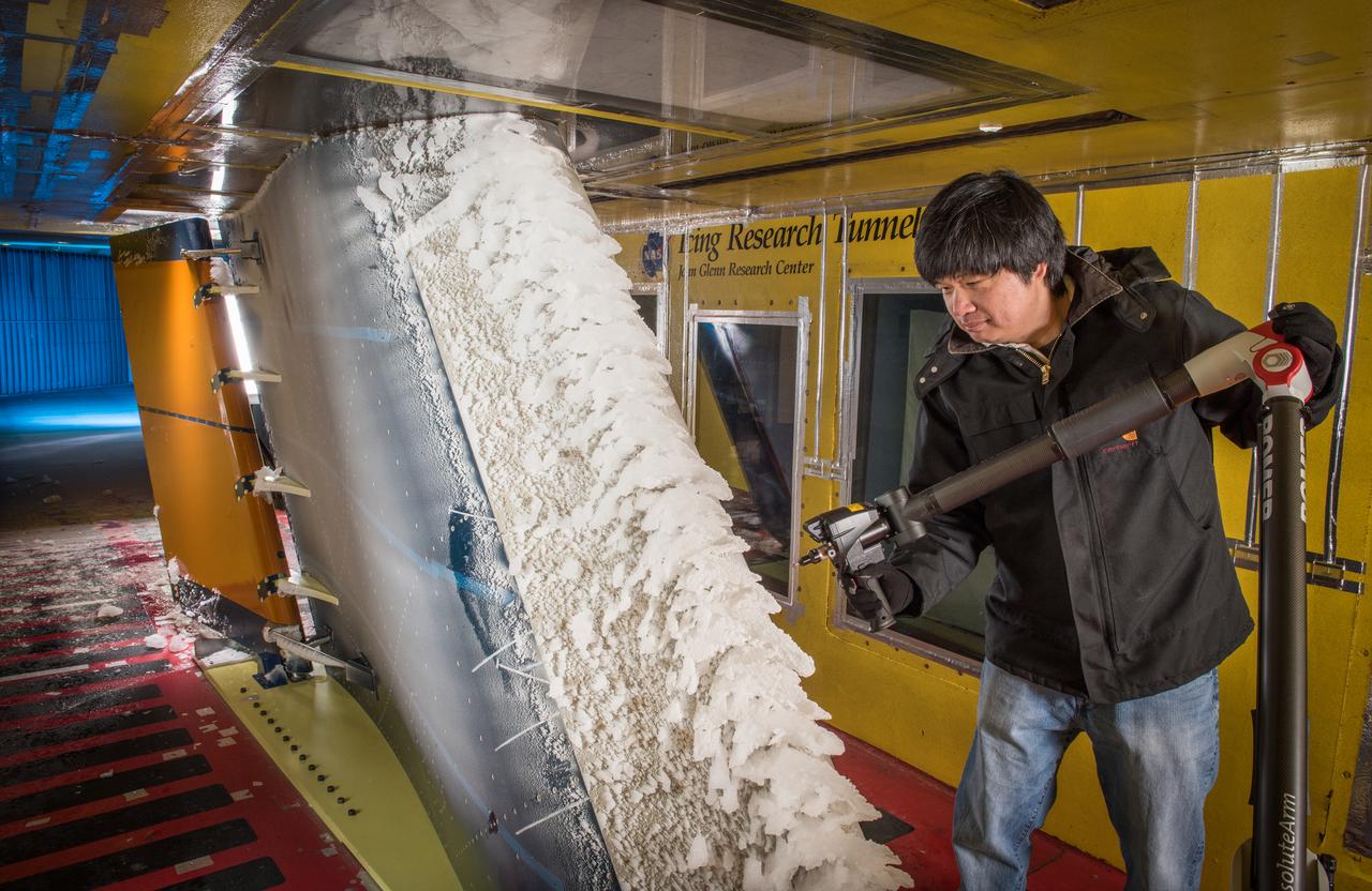
Technicians spray steam to help scrape off ice at the Icing Research Tunnel. The technicians need all the help they can get in sub-zero temperatures. Photo Credit: (NASA/Jordan Salkin)
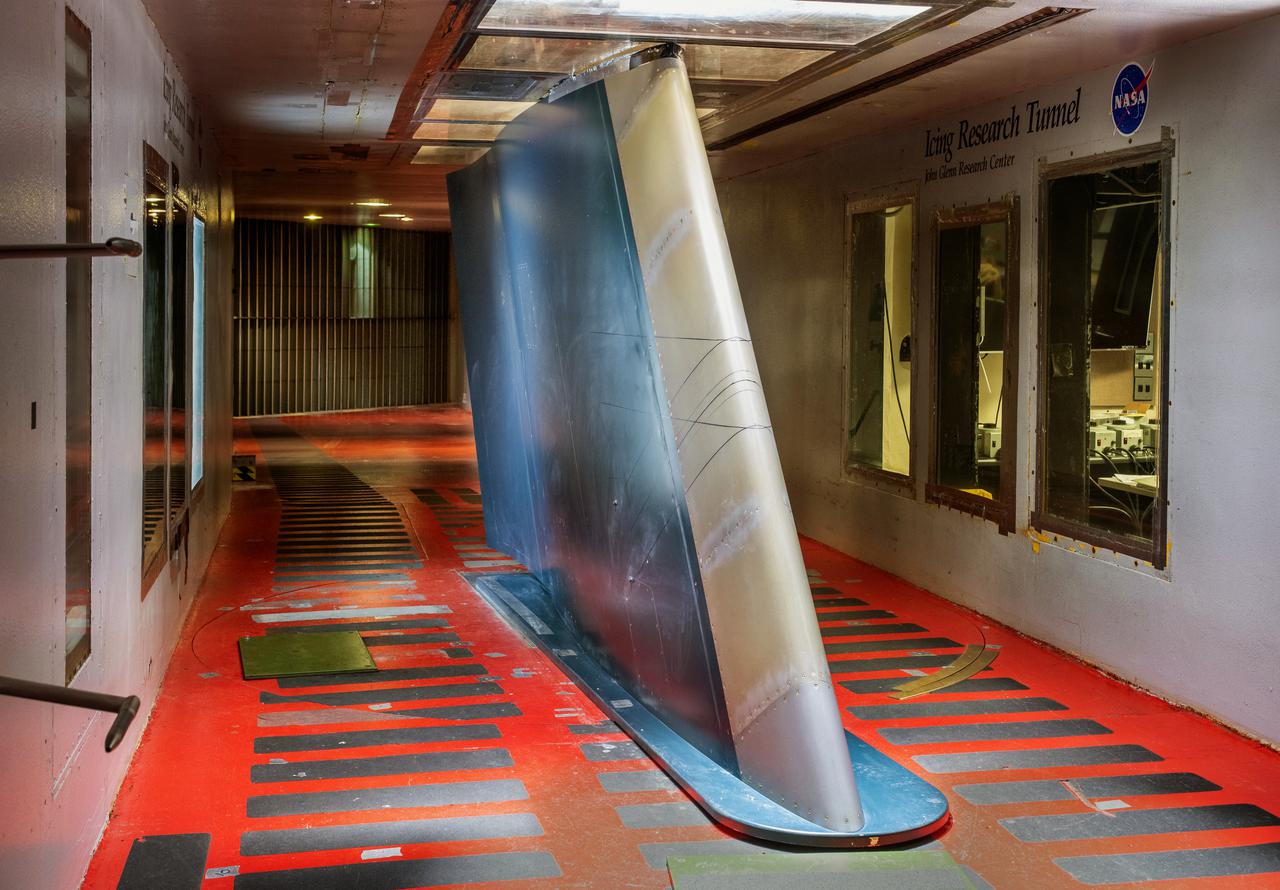
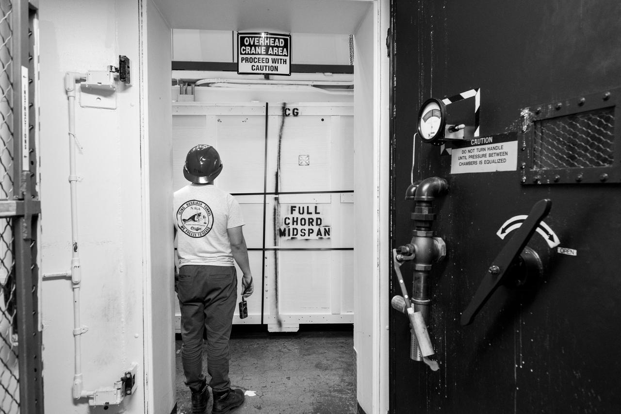
Common Research Model, CRM Full Chord and Midspan Test in the Icing Research Tunnel, IRT
CRM Full Chord Installation and Test Documentation Photos, Icing Research Tunnel
CRM Full Chord Installation and Test Documentation Photos, Icing Research Tunnel
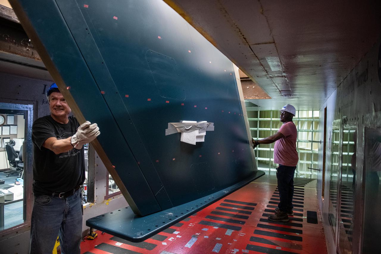
CRM Full Chord Installation and Test Documentation Photos, Icing Research Tunnel
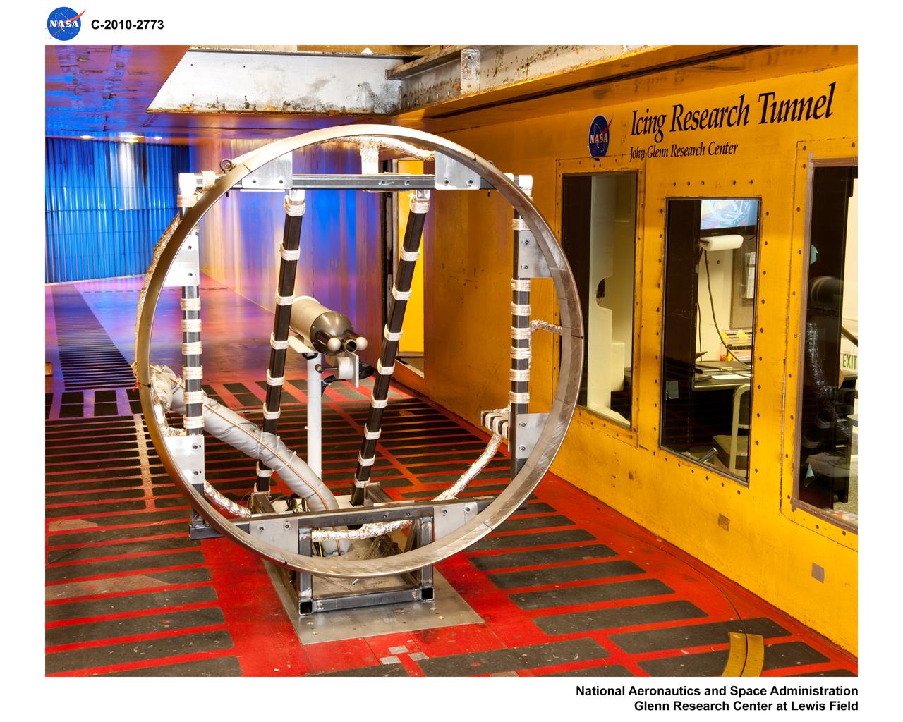
The Icing Research Tunnel (IRT) is the longest running, icing facility in the world and has been in operation since 1944. Most ice protection technologies in use today were largely developed at this facility. In this facility, natural icing conditions, such as the clouds being created here, are produced to test the effects of icing conditions on aircraft components such as wings tails and engine inlets.
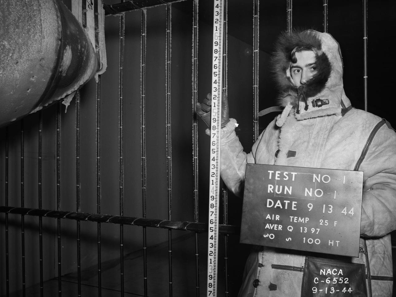
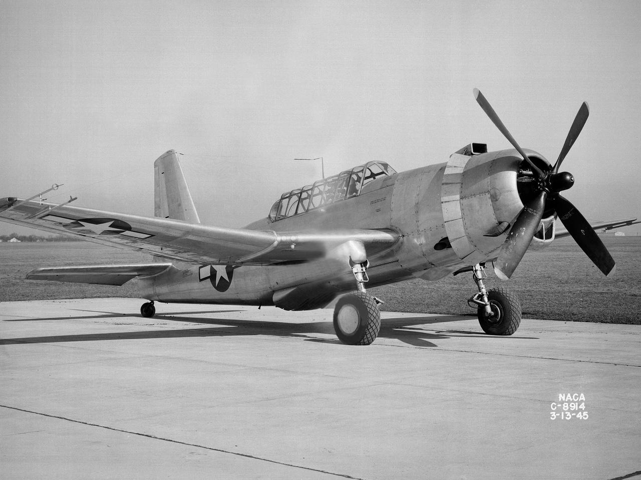
National Advisory Committee for Aeronautics (NACA) design engineers added the Icing Research Tunnel to the new Aircraft Engine Research Laboratory’s original layout to take advantage of the massive refrigeration system being constructed for the Altitude Wind Tunnel. The Icing Research Tunnel was built to study the formation of ice on aircraft surfaces and methods of preventing or eradicating that ice. Ice buildup adds extra weight, effects aerodynamics, and sometimes blocks airflow through engines. The Icing Research Tunnel is a closed-loop atmospheric wind tunnel with a 6- by 9-foot test section. The tunnel can produce speeds up to 300 miles per hour and temperatures from about 30 to –45⁰ F. Initially the tunnel used a spray bar system to introduce moisture into the airstream. NACA engineers struggled for nearly 10 years to perfect the spray system. The Icing Research Tunnel began testing in June of 1944. Initial testing, seen in this photograph, studied ice accumulation on propellers of a military aircraft. NACA reserach also produced a protected air scoop for the C–46 transport aircraft. A large number of C–46 aircraft were lost due to icing while flying supply runs over the Himalayas during World War II.

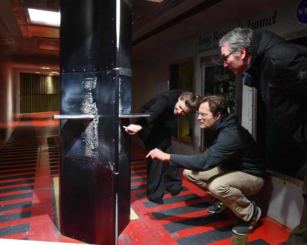
Curtis Flack (left) and Paul von Hardenberg (right) inspect the ice formation on the spinner of an Advanced Air Mobility proprotor model tested in the Icing Research Tunnel. The data from the test will be used by icing researchers to better understand the risks of icing on electric vertical takeoff and landing vehicles which will assist with the design and certification of new aircraft.
CRM Full Chord Installation and Test Documentation Photos, Icing Research Tunnel
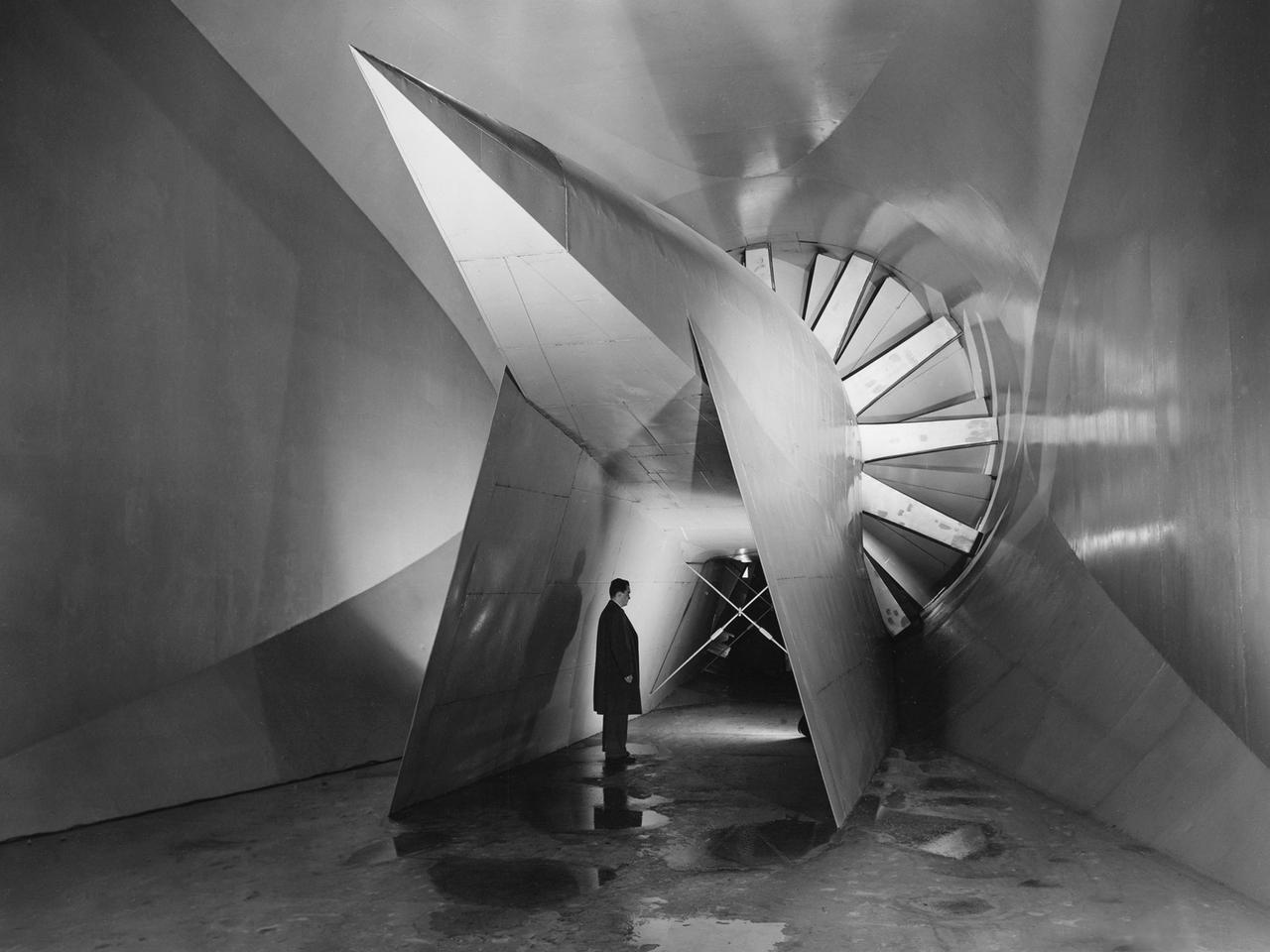
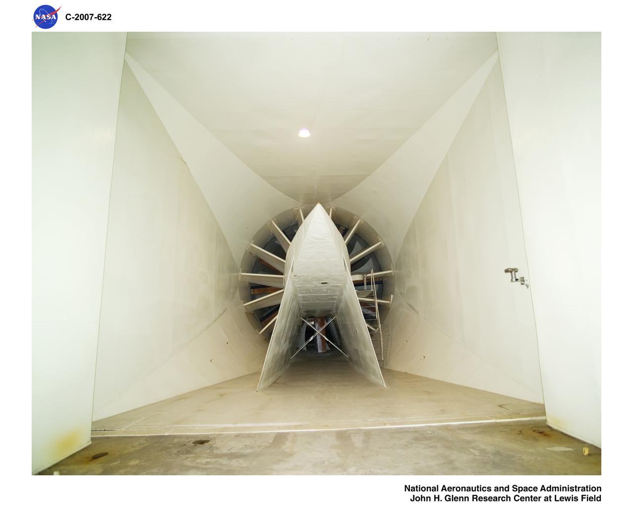
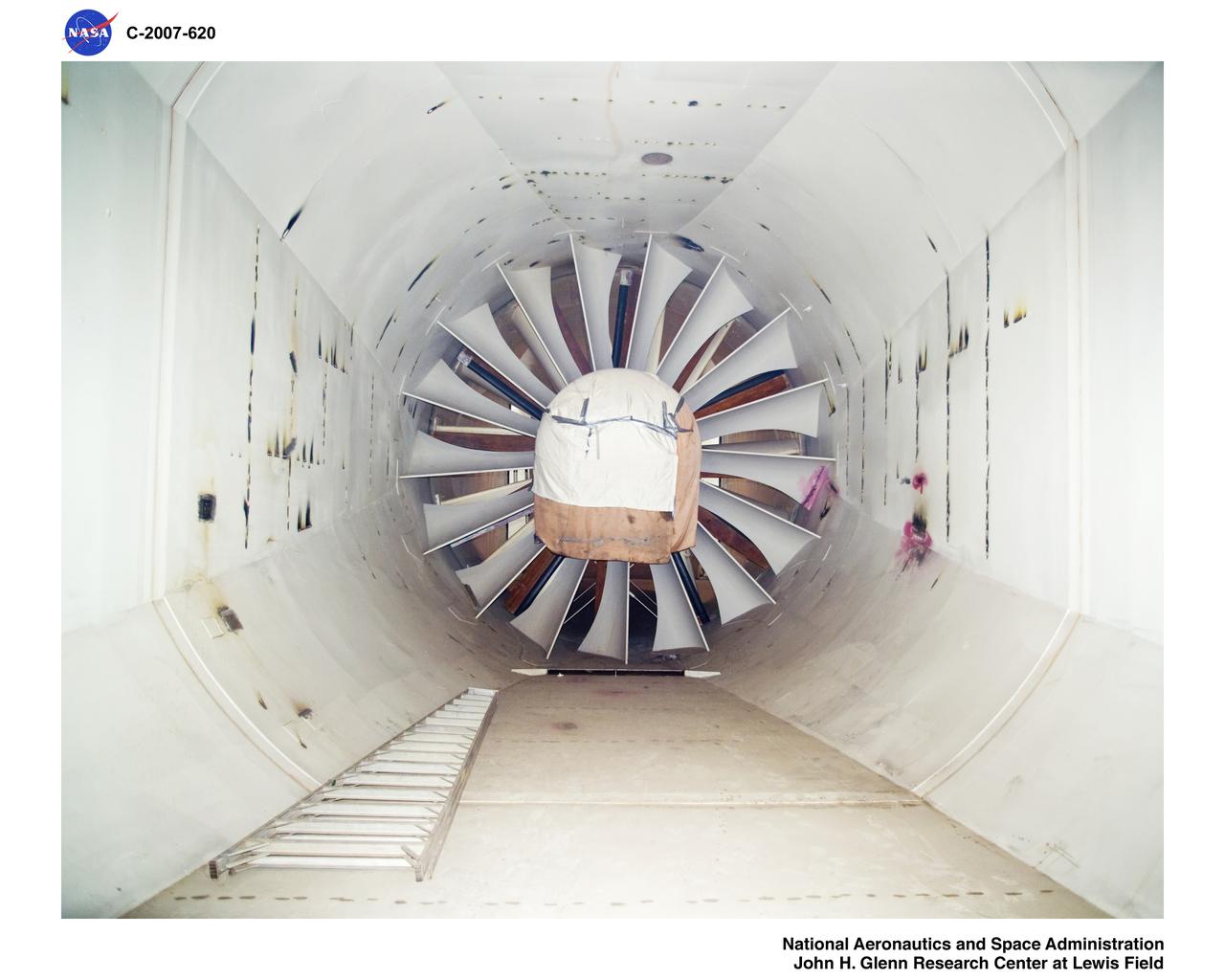
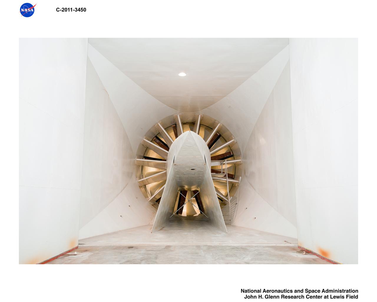
View of the drive fan for the Icing Research Tunnel at the National Advisory Committee for Aeronautics (NACA) Aircraft Engine Research Laboratory in Cleveland, Ohio. The tunnel was built in the early 1940s to study the formation of ice on aircraft surfaces and methods of preventing or eradicating that ice. Ice buildup adds extra weight, effects aerodynamics, and sometimes blocks airflow through engines. The original 4100-horsepower induction motor was coupled directly to the 24-foot-diameter fan. The 12 wooden fan blades were protected on their leading edge by a neoprene boot. The system could create air speeds up to 300 miles per hour through the tunnel’s 6- by 9-foot test section. The large tail faring extending from the center of the fan is used to guide the airflow down the tunnel in a uniform way. A new 5000-horsepower motor was installed in 1987, and the original fan blades were replaced in 1993.

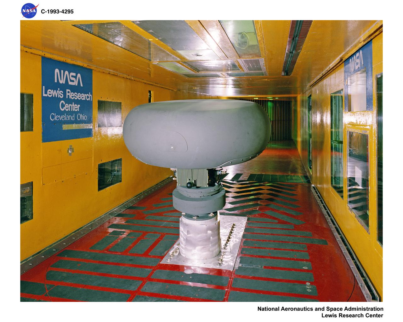
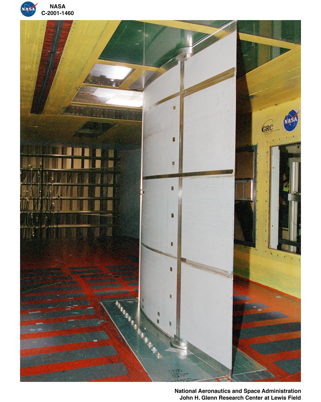
Technicians set up test hardware inside the test section of the Icing Research Tunnel at the National Aeronautics and Space Administration (NASA) Lewis Research Center. The Icing Research Tunnel was built in the early 1940s to study the formation of ice on aircraft surfaces and develop methods of preventing or eradicating that ice. Ice buildup is dangerous because it adds extra weight, effects aerodynamics, and sometimes blocks air flow through engines. The Icing Research Tunnel is a closed-loop atmospheric wind tunnel with a 6- by 9-foot test section. The tunnel can produce speeds up to 300 miles per hour and temperatures from 30 to -45 °F. NACA engineers struggled initially to perfect a spray bar system to introduce moisture into the airstream. The tunnel was shut down in the late 1950s as the center focused its energy exclusively on space. Industrial customers began using the tunnel sporadically, then steadily, in the 1960s. Boeing, Aerojet, Lockheed, Sikorsky, Beech and others ran tests during the 1960s. Boeing analyzed engine inlets for the CH-47 Chinook, CH-46 (Sea Knight) and CH-113. This photograph was taken during a series of 100 ice-phobic coatings for the Federal Aviation Administration. They found that many of the coatings reduced ice adhesion to the test sample, but they could not be used for aircraft applications.
A Bell P-39 Airacobra in the NACA Aircraft Engine Research Laboratory’s Icing Research Tunnel for a propeller deicing study. The tunnel, which began operation in June 1944, was built to study the formation of ice on aircraft surfaces and methods of preventing or eradicating that ice. Ice buildup adds extra weight to aircraft, effects aerodynamics, and sometimes blocks airflow through engines. NACA design engineers added the Icing Research Tunnel to the new AERL’s original layout to take advantage of the massive refrigeration system being constructed for the Altitude Wind Tunnel. The Icing Research Tunnel is a closed-loop atmospheric wind tunnel with a 6- by 9-foot test section. The tunnel can produce speeds up to 300 miles per hour and temperatures from about 30 to –45⁰ F. During World War II AERL researchers analyzed different ice protection systems for propeller, engine inlets, antennae, and wings in the icing tunnel. The P-39 was a vital low-altitude pursuit aircraft of the US during the war. NACA investigators investigated several methods of preventing ice buildup on the P-39’s propeller, including the use of internal and external electrical heaters, alcohol, and hot gases. They found that continual heating of the blades expended more energy than the aircraft could supply, so studies focused on intermittent heating. The results of the wind tunnel investigations were then compared to actual flight tests on aircraft.
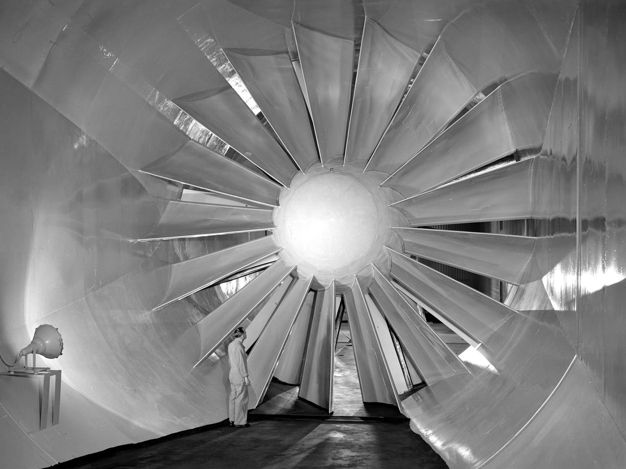
A researcher examines the drive fan inside the Icing Research Tunnel at the National Advisory Committee for Aeronautics (NACA) Flight Propulsion Research Laboratory in Cleveland, Ohio. The facility was built in the mid-1940s to simulate the atmospheric conditions that caused ice to build up on aircraft. Carrier Corporation refrigeration equipment reduced the internal air temperature to -45⁰ F, and a spray bar system injected water droplets into the air stream. The 24-foot diameter drive fan, seen in this photograph, created air flow velocities up to 400 miles per hour. The 1950s were prime years for the Icing Research Tunnel. NACA engineers had spent the 1940s trying to resolve the complexities of the spray bar system. The final system put into operation in 1950 included six horizontal spray bars with 80 nozzles that produced a 4- by 4-foot cloud in the test section. The icing tunnel was used for extensive testing of civilian and military aircraft components in the 1950s. The NACA also launched a major investigation of the various methods of heating leading edge surfaces. The hot-air anti-icing technology used on today’s commercial transports was largely developed in the facility during this period. Lewis researchers also made significant breakthroughs with icing on radomes and jet engines. Although the Icing Research Tunnel yielded major breakthroughs in the 1950s, the Lewis icing research program began tapering off as interest in the space program grew. The icing tunnel’s use declined in 1956 and 1957. The launch of Sputnik in October 1957 signaled the end of the facility’s operation. The icing staff was transferred to other research projects and the icing tunnel was temporarily mothballed.
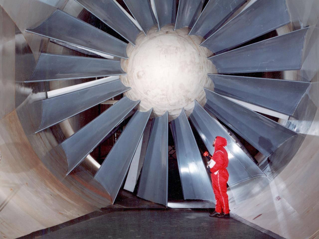
The drive fan for the Icing Research Tunnel at the National Aeronautics and Space Administration (NASA) Lewis Research Center in Cleveland, Ohio. The Lewis Icing Research Program, which began during World War II, utilized both research aircraft and the icing tunnel throughout the 1940s and 1950s. The research program was cancelled in 1958 as Lewis focused on space. The tunnel continued to be used occasionally for industrial customers in the 1960s and early 1970s. Lewis’ icing research was formally reinstituted just months before this photograph in 1978. The Icing Research Tunnel’s original 4100-horsepower induction motor was coupled directly to the 24-foot-diameter fan. Neoprene boots protected the leading edges of the 12 spruce fan blades. The system generated air speeds up to 300 miles per hour through the tunnel’s 6- by 9-foot test section. A large tail faring extended from the center of the fan to uniformly guide the airflow down the tunnel. NASA Headquarters ordered modifications to the Icing Research Tunnel in 1985 after wooden fan blades in a wind tunnel at Langley Research Center failed. Despite the fact that the large hub, seen in the center of the fan, provided an extra layer of protection against blade failure, Headquarters ordered the installation of a new set of wooden blades. The blades were ordered but not installed. The tunnel technicians instead agreed to inspect the fan after each run. A new 5000-horsepower motor was installed in 1987, and the original fan blades were finally replaced in 1993.
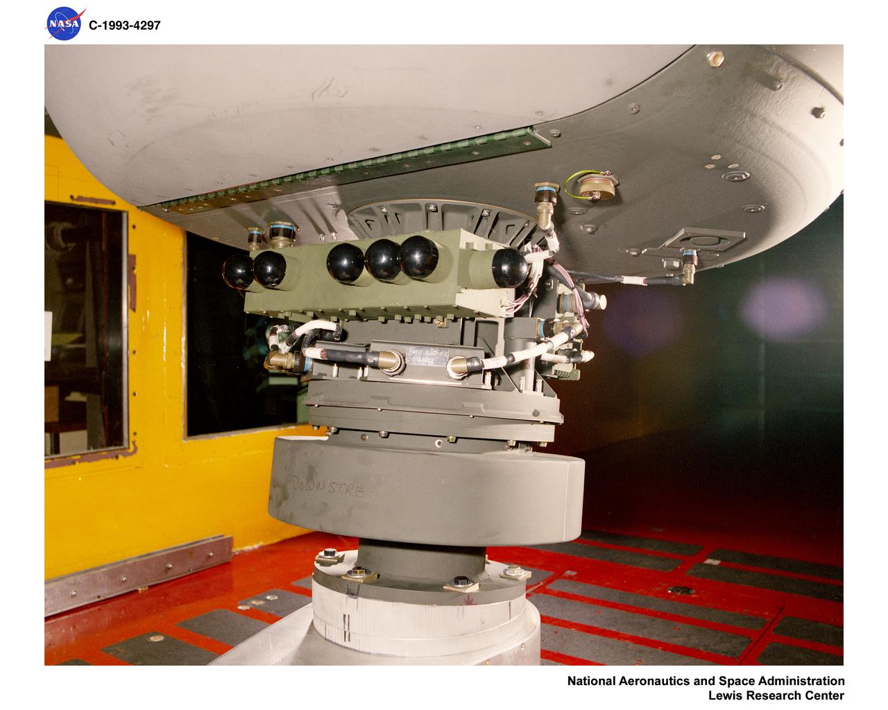
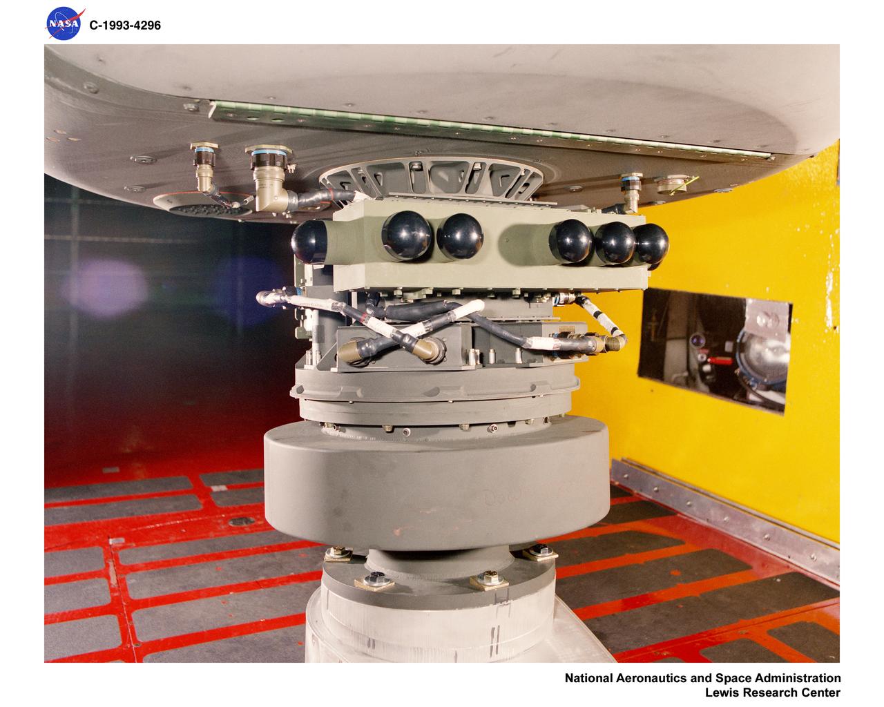
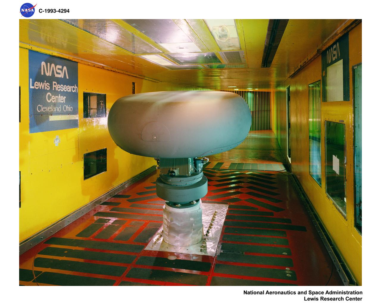
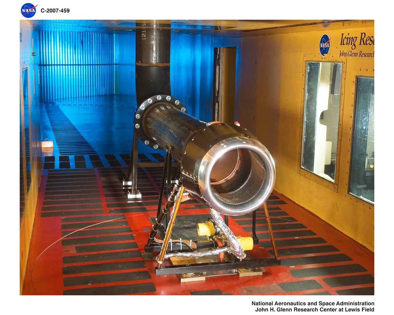
An AH-64 (Apache) Longbow fire control full size radar photographed during icing tests in the Icing Research wind tunnel. Built at the end of World War II, the Icing Research Tunnel is the oldest and largest refrigerated icing wind tunnel in the world. It can produce winds that travel up to 395 miles per hour and reach temperatures as low as -30 degrees Fahrenheit. The facility simulates ice formation during flight by spraying a cloud of super-cooled water droplets onto an aircraft component or model.

Significant ice build-up on the Simulated Inter-compressor Duct Research Model (SIDRM) at the Icing Research Tunnel. Photo Credit: (NASA/Jordan Salkin)
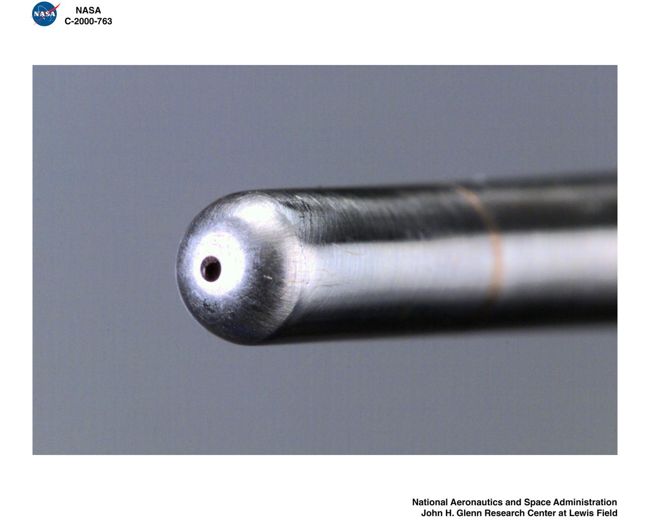
Test engineers clean the ice cloud detection probe in the Icing Research Tunnel in between test runs. Steam is used to melt the accumulated ice on the detection probe. The test engineers need to wear goggles to protect them from the laser light that the probe emits. The laser detects water content and ice particles in the cloud that the wind tunnel produces. This process is done to calibrate the tunnel for research by characterizing the cloud flow.
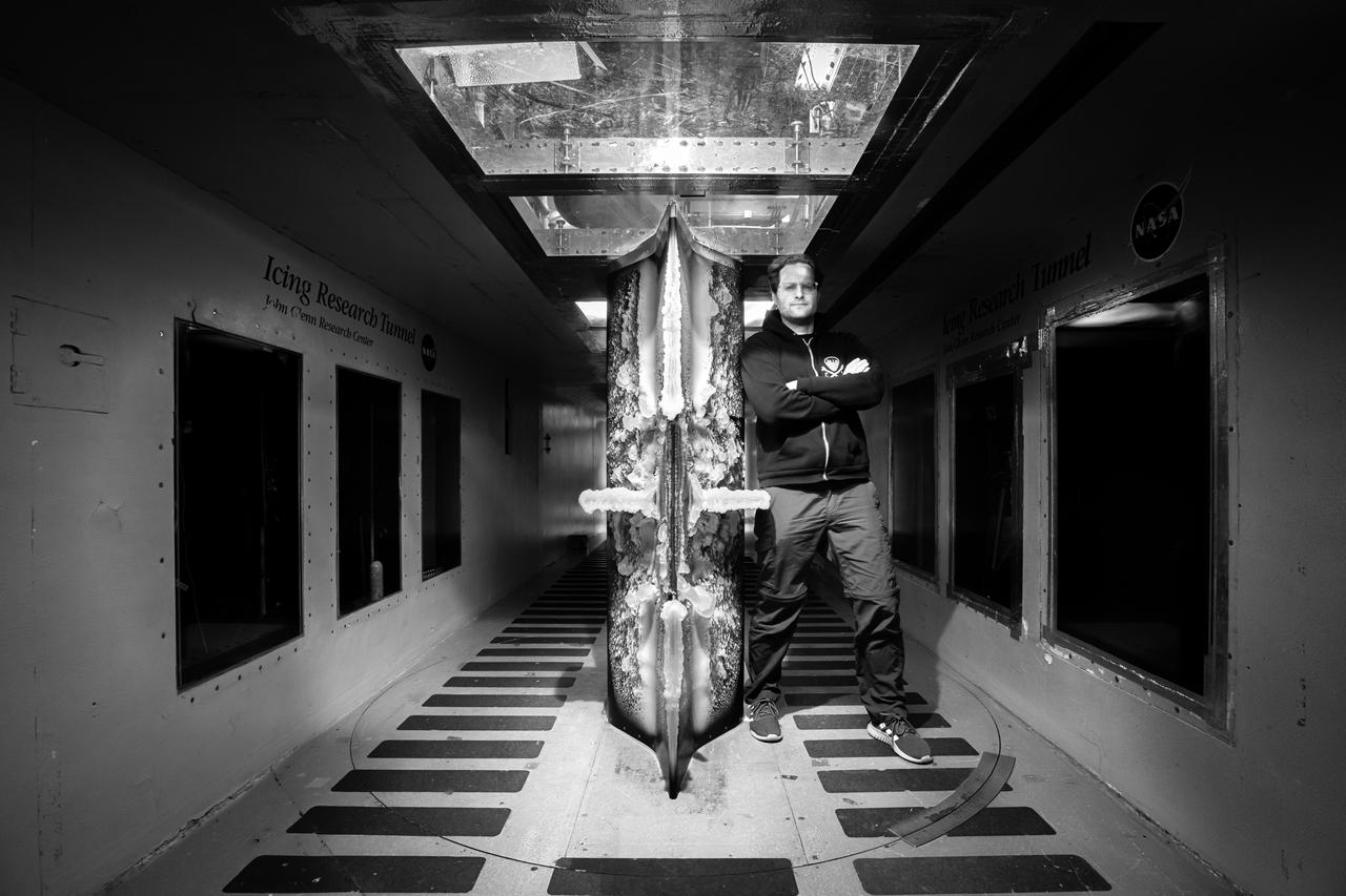
Lead researcher Tadas Bartkus poses after a run of his test with significant ice build-up on the Simulated Inter-compressor Duct Research Model (SIDRM) at the Icing Research Tunnel. Photo Credit: (NASA/Jordan Salkin)
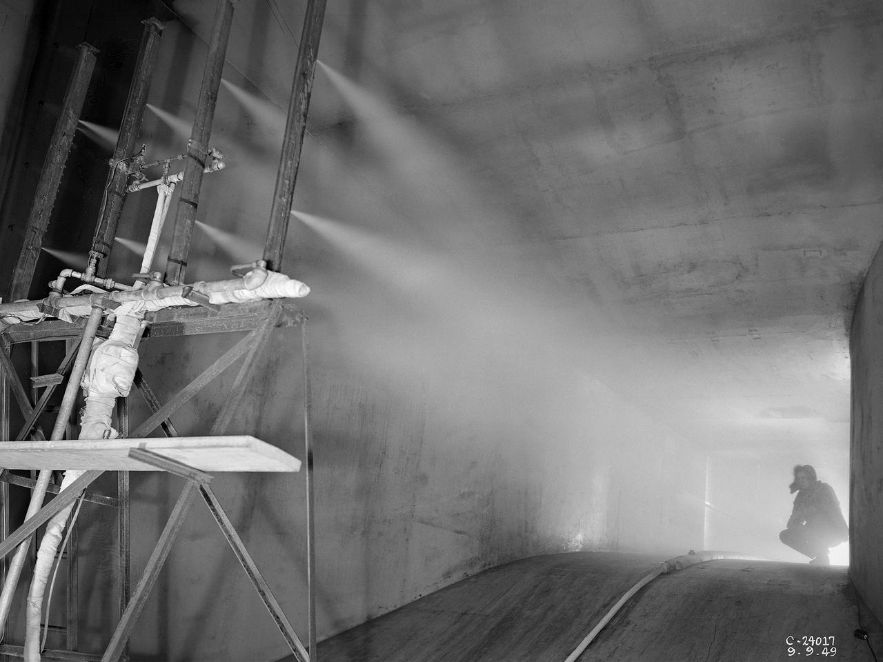
The spray bar system introduces water droplets into the Icing Research Tunnel’s air stream at the National Advisory Committee for Aeronautics (NACA) Lewis Flight Propulsion Laboratory. The icing tunnel was designed in the early 1940s to study ice accretion on airfoils and models. The Carrier Corporation designed a refrigeration system that reduced temperatures to -45° F. The tunnel’s drive fan generated speeds up to 400 miles per hour. The uniform injection of water droplets to the air was a key element of the facility’s operation. The system had to generate small droplets, distribute them uniformly throughout the airstream, and resist freezing and blockage. The Icing Research Tunnel’s designers struggled to develop a realistic spray system because they did not have access to data on the size of naturally occurring water droplets. For five years a variety of different designs were painstakingly developed and tested before the system was perfected. This photograph shows one of the trials using eight air-atomizing nozzles placed 48 feet upstream from the test section. A multi-cylinder device measured the size, liquid content, and distribution of the water droplets. The final system that was put into operation in 1950 included six horizontal spray bars with 80 nozzles that produced a 4- by 4-foot cloud in the test section. The Icing Research Tunnel produced excellent data throughout the 1950s and provided the basis for a hot air anti-icing system used on many transport aircraft.
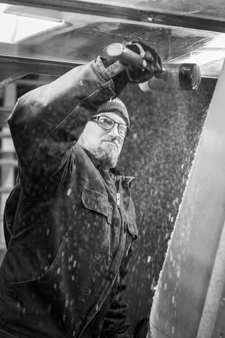
A technician is shown preparing the research model for its next test condition by removing ice accretion. Photo Credit: (NASA/Jordan Salkin)
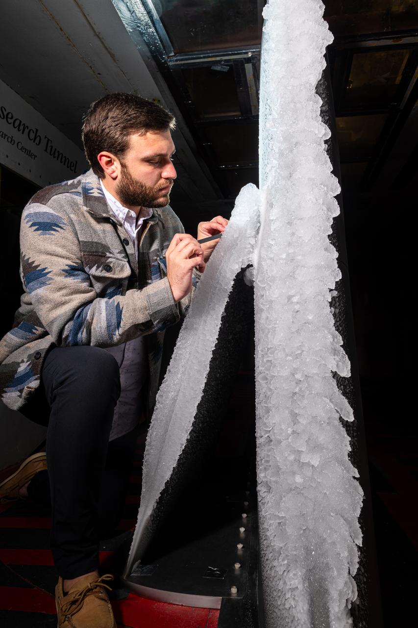
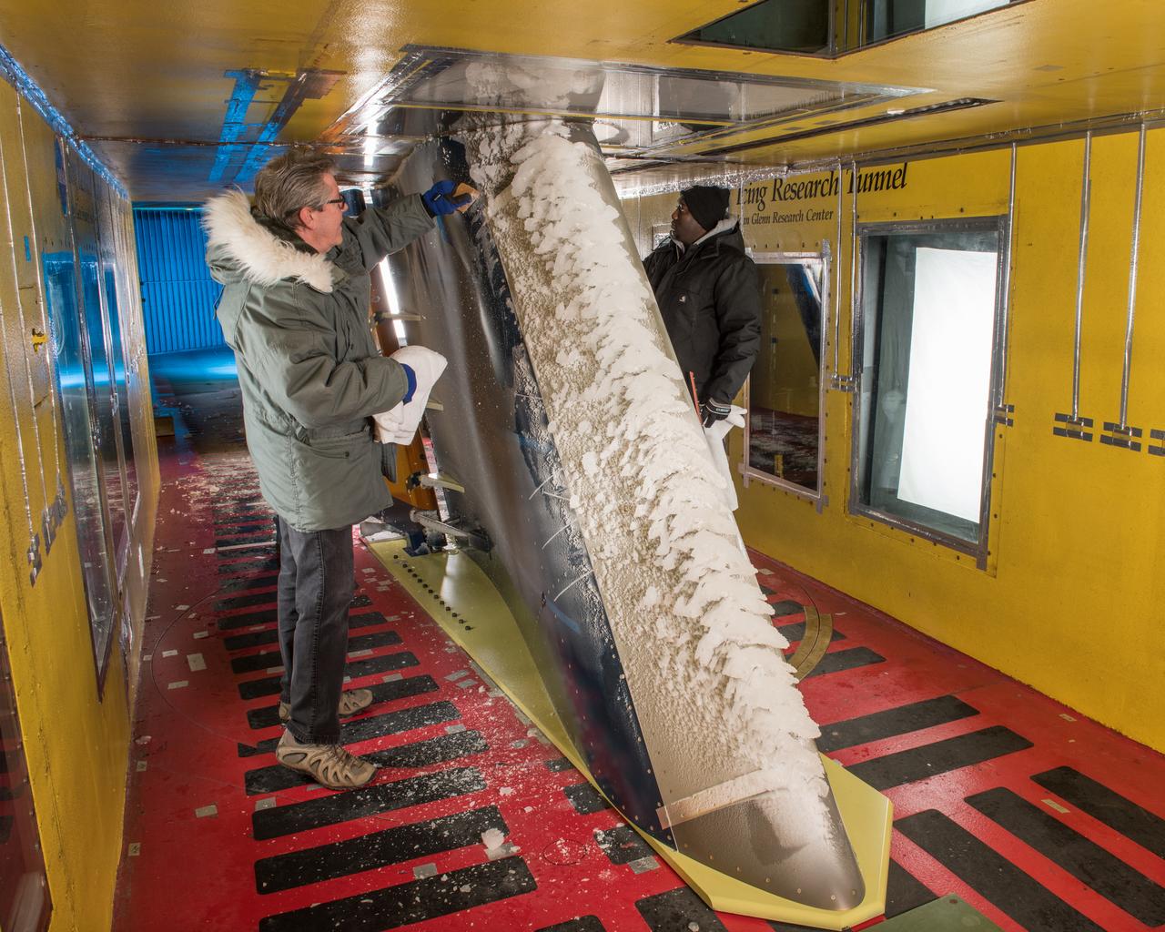
Thomas Ozoroski, an Icing Researcher, is shown documenting ice accretion on the leading edge of the next-generation Transonic Truss-Braced Wing design at NASA Glenn's Icing Research Center. This critical research will help understand icing effects for future, high-lift, ultra-efficient aircraft. Photo Credit: (NASA/Jordan Salkin)
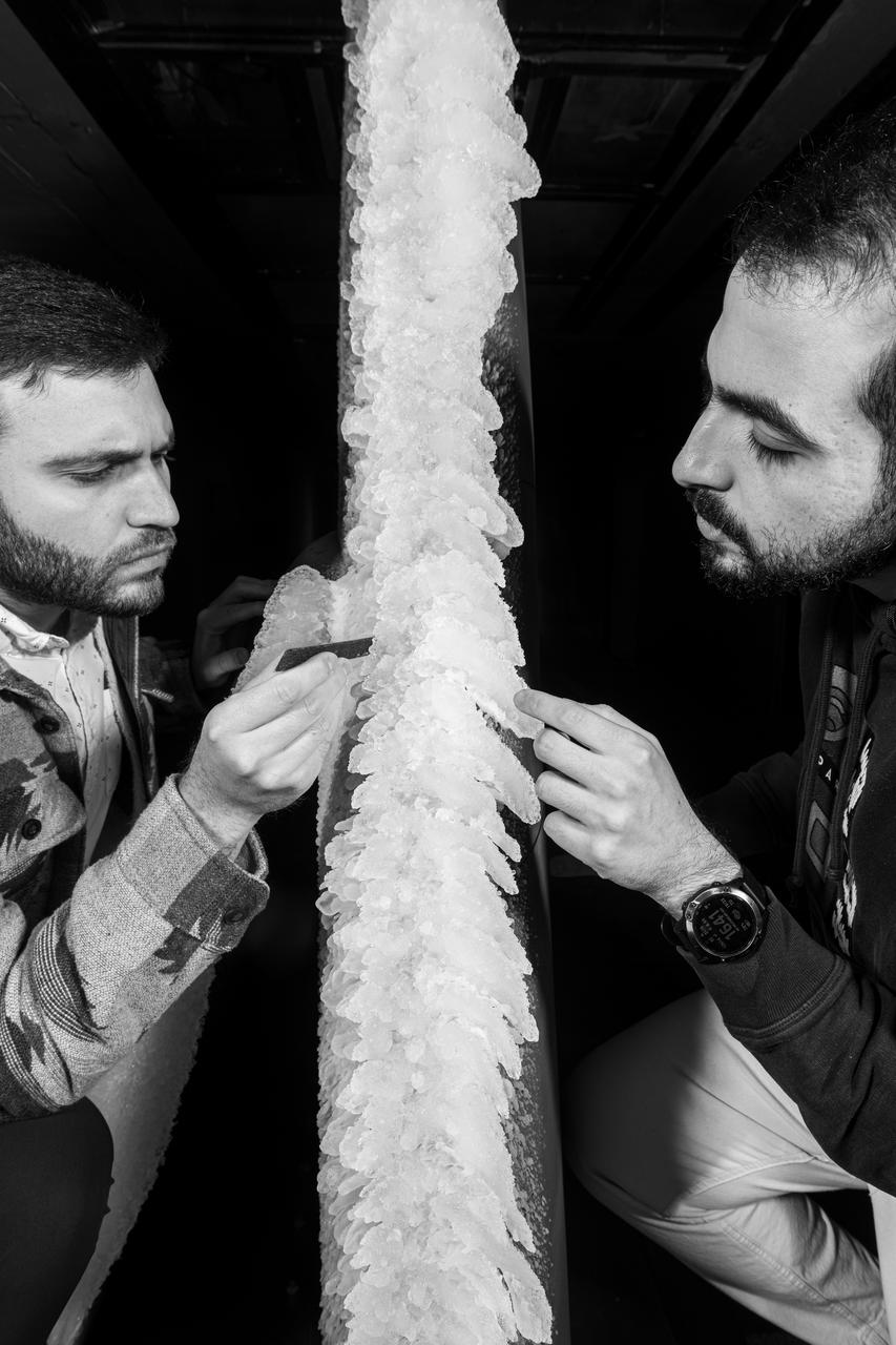
Zaid Sabri and Thomas Ozoroski, Icing Researchers, are shown documenting ice accretion on the leading edge of the next-generation Transonic Truss-Braced Wing design at NASA Glenn's Icing Research Center. This critical research will help understand icing effects for future, high-lift, ultra-efficient aircraft. Photo Credit: (NASA/Jordan Salkin)
Ice accretion is shown on the leading edge of the next-generation Transonic Truss-Braced Wing design at NASA Glenn's Icing Research Center. This critical research will help understand icing effects for future, high-lift, ultra-efficient aircraft. Photo Credit: (NASA/Jordan Salkin)
THE LONGBOW MODEL IN THE ICING RESEARCH TUNNEL
THE LONGBOW MODEL IN THE ICING RESEARCH TUNNEL
THE LONGBOW MODEL IN THE ICING RESEARCH TUNNEL
THE LONGBOW MODEL IN THE ICING RESEARCH TUNNEL
Hardware Shoot in the Icing Research Tunnel
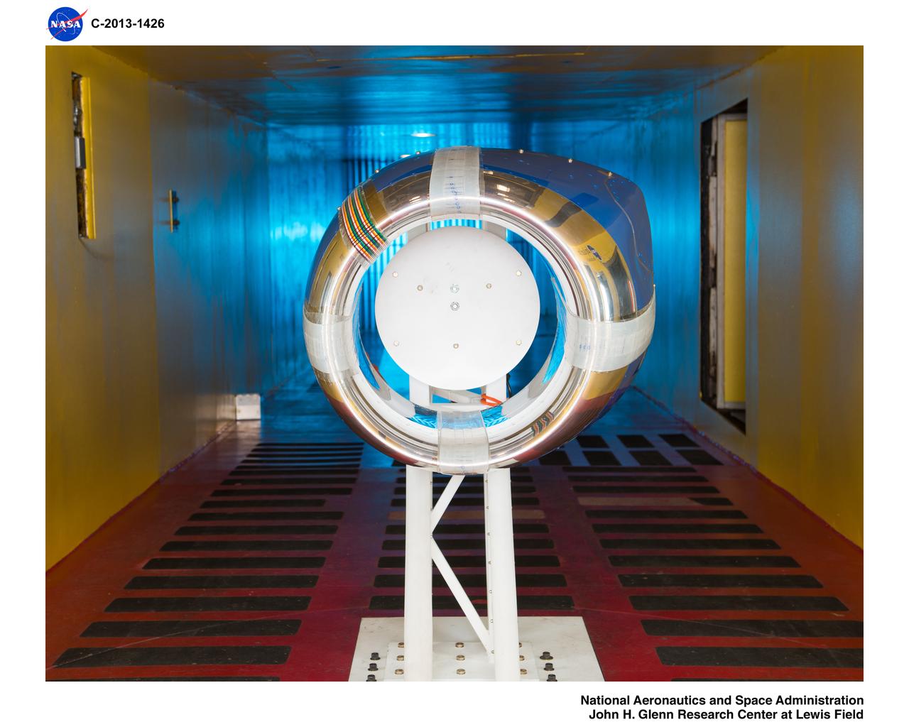
Model in the Icing Research Tunnel, IRT
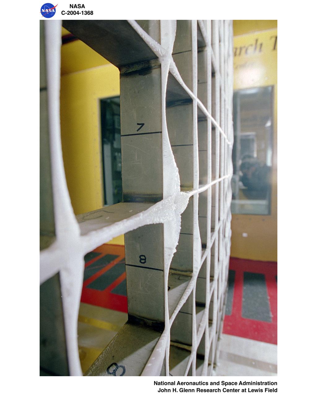
Icing Research Tunnel's icing grid with super-cooled large droplet (SLD) icing conditions
Common Research Model, CRM, in the Icing Research Tunnel, IRT
Common Research Model, CRM, in the Icing Research Tunnel, IRT
IMPINGEMENT TEST IN ICING RESEARCH TUNNEL IRT
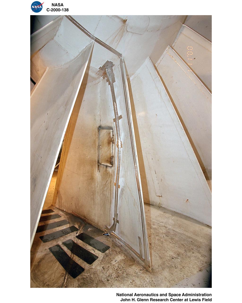
Icing Research Tunnel (IRT) "AB Corner" Rehabilitation
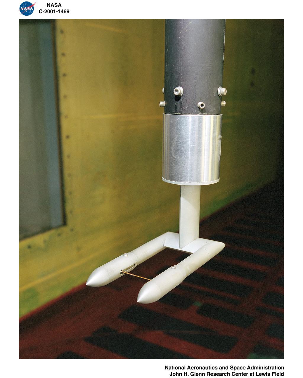
IRT - ICING RESEARCH TUNNEL WAKE SURVEY PROBE
IMPINGEMENT TEST IN ICING RESEARCH TUNNEL IRT
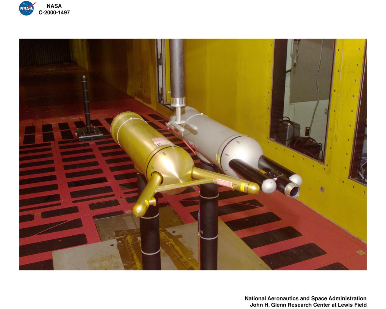
INSTRUMENTATION COMPARISON HARDWARE IN ICING RESEARCH TUNNEL IRT
Icing Research Tunnel (IRT) "AB Corner" Rehabilitation
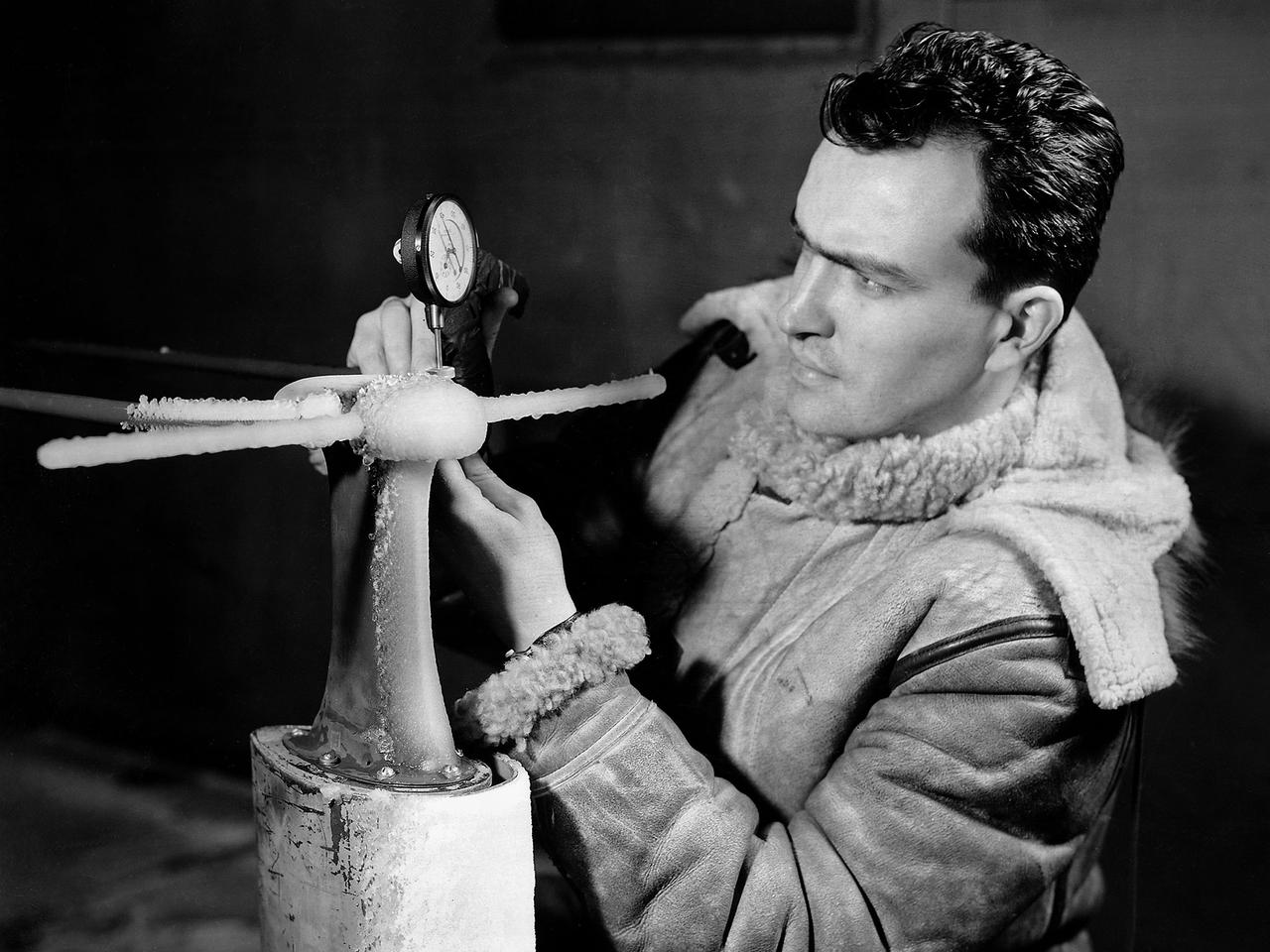
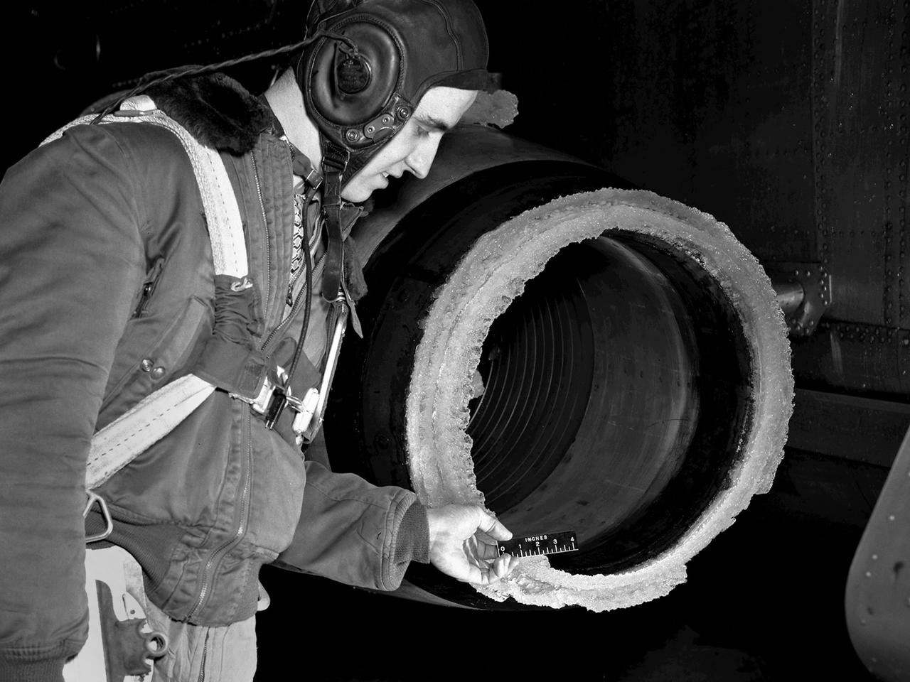
A National Advisory Committee for Aeronautics (NACA) researcher measures the ice thickness on a landing antenna model in the Icing Research Tunnel at the Aircraft Engine Research Laboratory. NACA design engineers added the Icing Research Tunnel to the original layout of the new Aircraft Engine Research Laboratory to take advantage of the massive refrigeration system being built for the Altitude Wind Tunnel. The Icing Research Tunnel was built to study the formation of ice on aircraft surfaces and methods of preventing or eradicating that ice. Ice buildup adds extra weight, effects aerodynamics, and sometimes blocks air flow through engines. The Icing Research Tunnel is a closed-loop atmospheric wind tunnel with a 6- by 9-foot test section. Carrier Corporation refrigeration equipment reduced the internal air temperature to -45 degrees F and a spray bar system injected water droplets into the air stream. The 24-foot diameter drive fan, seen in this photograph, created air flows velocities up to 400 miles per hour. The Icing Research Tunnel began testing in June of 1944. Early testing, seen in this photograph, studied ice accumulation on propellers and antenna of a military aircraft. The Icing Research Tunnel’s designers, however, struggled to develop a realistic spray system since they did not have access to data on the size of naturally occurring water droplets. The system would have to generate small droplets, distribute them uniformly throughout the airstream, and resist freezing and blockage. For five years a variety of different designs were painstakingly developed and tested before the system was perfected.
Isokinetic and Multi Wire Probes in the Icing Research Tunnel, IRT, Test Section
THERMAL CODE I TEST HARDWARE IN ICING RESEARCH TUNNEL IRT

WICHITA STATE UNIVERSITY / ICING RESEARCH TUNNEL IMPINGMENT DYE TEST
General Atomics - Predator B Inlet Model in the Icing Research Tunnel
General Electric Aviation - Engine Splitter Booster Model in the Icing Research Tunnel

WICHITA STATE UNIVERSITY / ICING RESEARCH TUNNEL IMPINGMENT DYE TEST
ICING RESEARCH TUNNEL IRT FORCE BALANCE CALIBRATION HARDWARE
WICHITA STATE UNIVERSITY / ICING RESEARCH TUNNEL IRT DYE TEAM

WICHITA STATE UNIVERSITY / ICING RESEARCH TUNNEL IMPINGMENT DYE TEST
General Atomics - Predator B Inlet Model in the Icing Research Tunnel
WICHITA STATE UNIVERSITY / ICING RESEARCH TUNNEL IMPINGMENT DYE TEST
THERMAL CODE I TEST HARDWARE IN ICING RESEARCH TUNNEL IRT
S-3 Viking 1/3 Wing Section in the Icing Research Tunnel
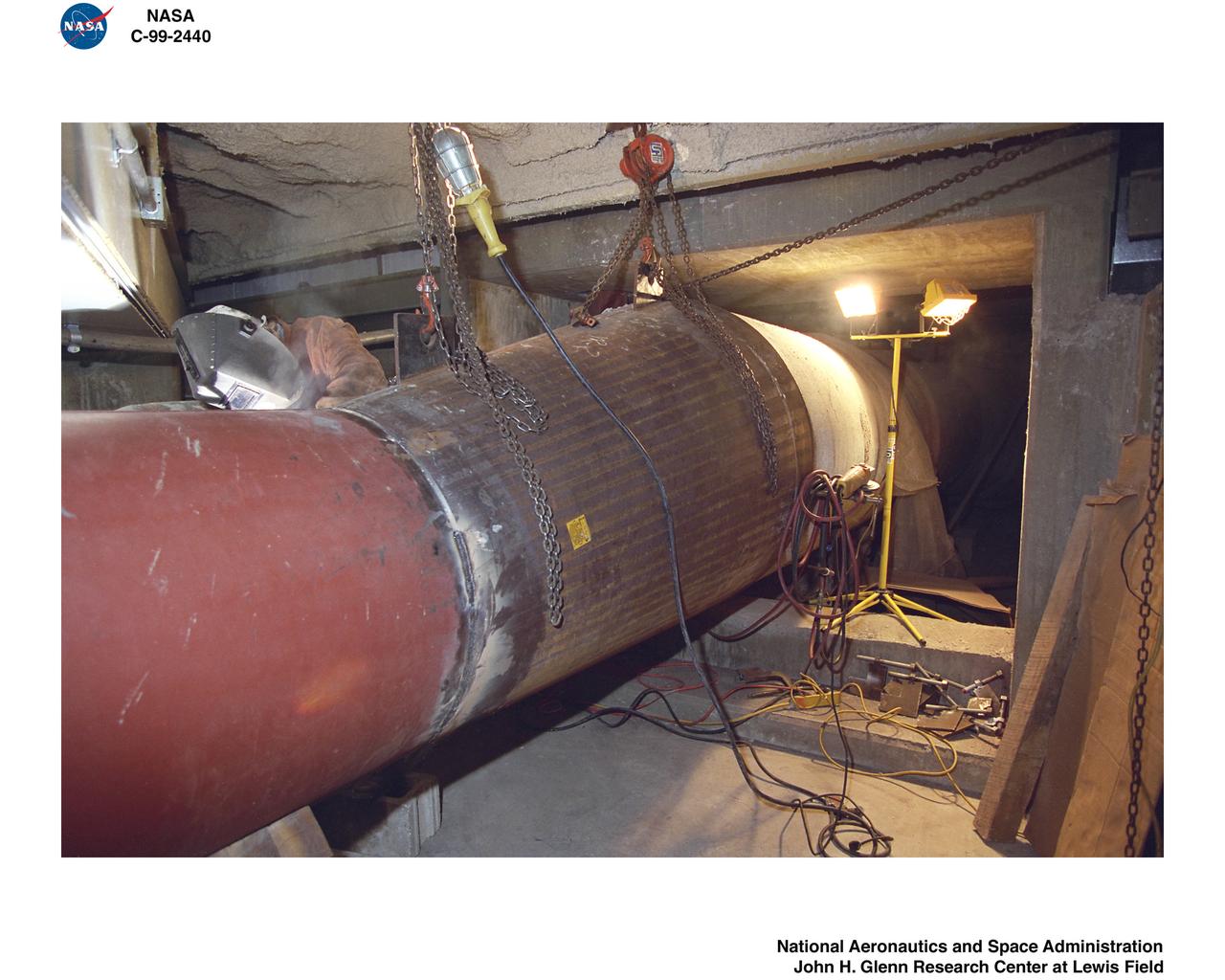
1999 CONSTRUCTION OF FACILITY ICING RESEARCH TUNNEL IRT HEAT EXCHANGER REPLACEMENT
1999 CONSTRUCTION OF FACILITY ICING RESEARCH TUNNEL IRT HEAT EXCHANGER REPLACEMENT
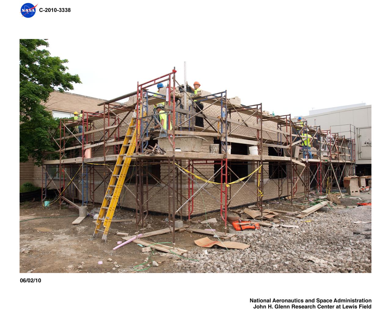
Icing Research Tunnel (IRT) Expansion Addition Construction Documentation
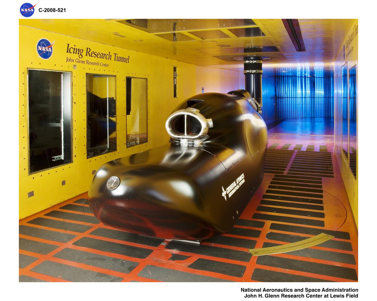
General Atomics - Predator B Inlet Model in the Icing Research Tunnel
Common Research Model, CRM, in the Icing Research Tunnel, IRT, Installation of Test Hardware
A Bell P-39 Airacobra in the NACA Aircraft Engine Research Laboratory’s Icing Research Tunnel for a propeller deicing study. The tunnel, which began operation in June 1944, was built to study the formation of ice on aircraft surfaces and methods of preventing or eradicating that ice. Ice buildup adds extra weight to aircraft, effects aerodynamics, and sometimes blocks airflow through engines. NACA design engineers added the Icing Research Tunnel to the new AERL’s original layout to take advantage of the massive refrigeration system being constructed for the Altitude Wind Tunnel. The Icing Research Tunnel is a closed-loop atmospheric wind tunnel with a 6- by 9-foot test section. The tunnel can produce speeds up to 300 miles per hour and temperatures from about 30 to -45⁰ F. During World War II AERL researchers analyzed different ice protection systems for propeller, engine inlets, antennae, and wings in the icing tunnel. The P-39 was a vital low-altitude pursuit aircraft of the US during the war. NACA investigators investigated several methods of preventing ice buildup on the P-39’s propeller, including the use of internal and external electrical heaters, alcohol, and hot gases. They found that continual heating of the blades expended more energy than the aircraft could supply, so studies focused on intermittent heating. The results of the wind tunnel investigations were then compared to actual flight tests on aircraft.
Construction of the Icing Research Tunnel, IRT, Refrigeration Plant-Newly Installed Heat Exchanger
The FJ33 Engine Inlet from Williams International being tested in the Icing Research Tunnel

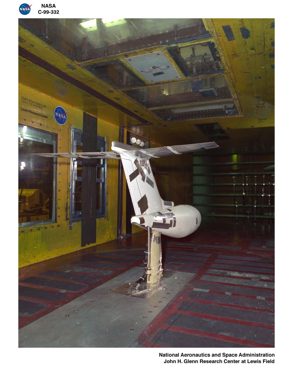
Particle-image velocimetry (PIV) is performed on the upper surface of a pitching airfoil in the NASA Glenn Icing Research Tunnel. PIV is a laser-based flow velocity measurement technique used widely in wind tunnels. These experiments were conducted as part of a research project focused on enhancing rotorcraft speed, efficiency and maneuverability by suppressing dynamic stall.
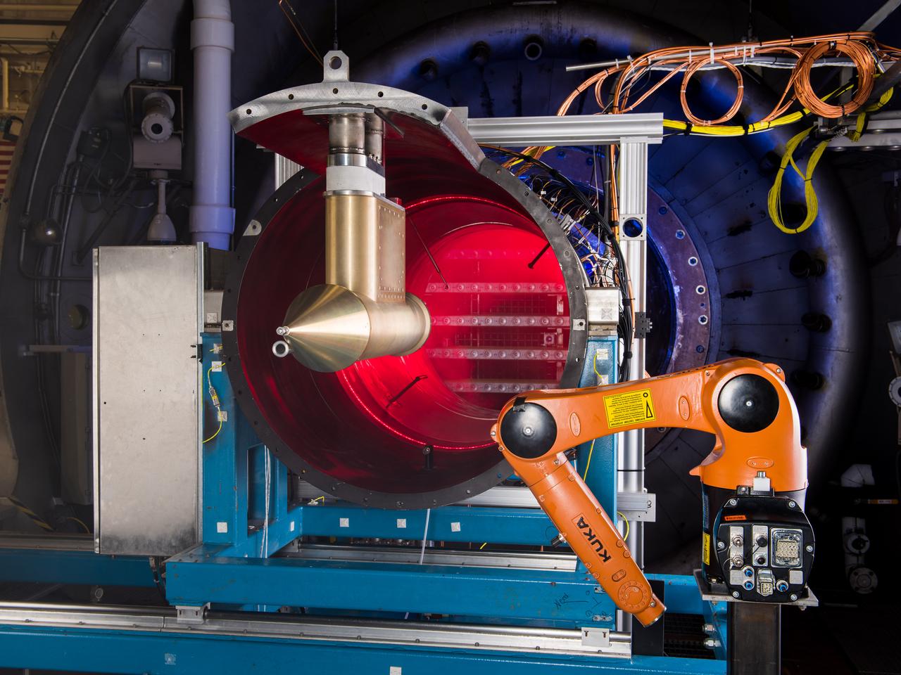
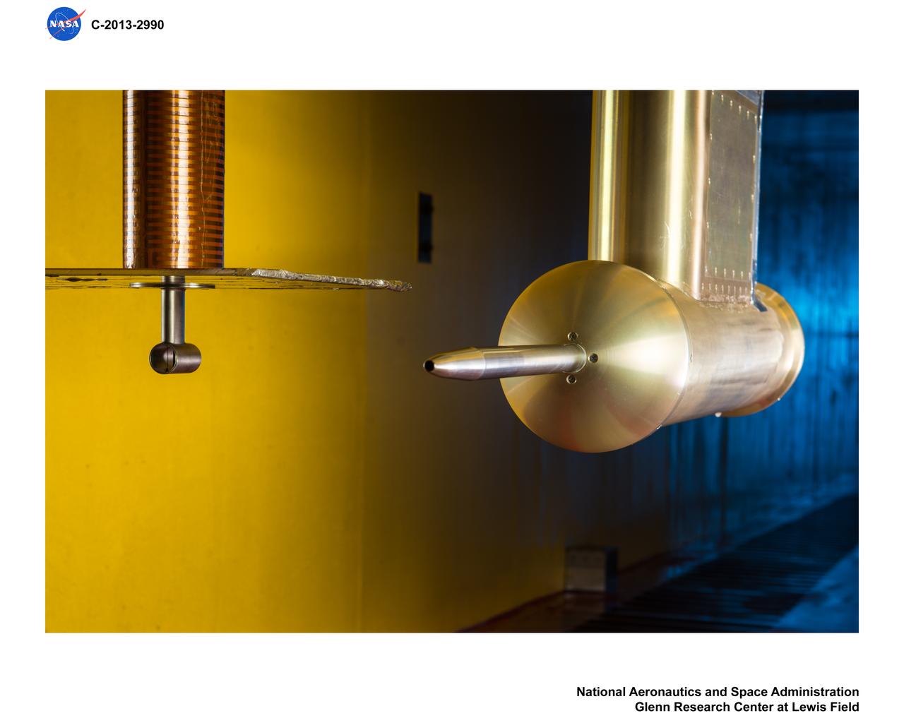
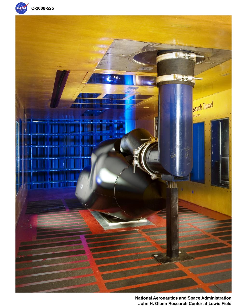
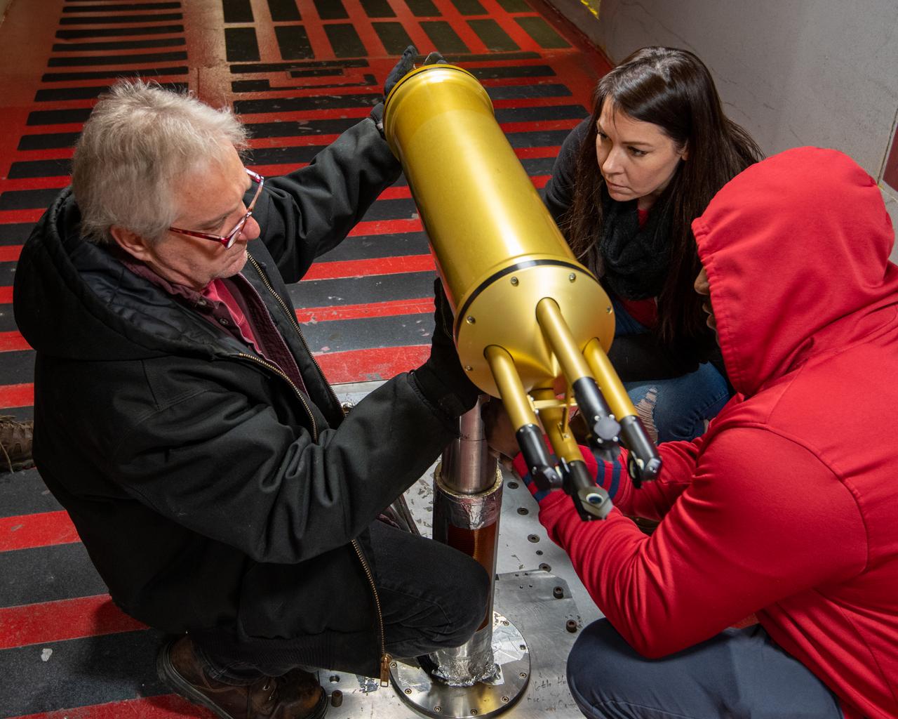
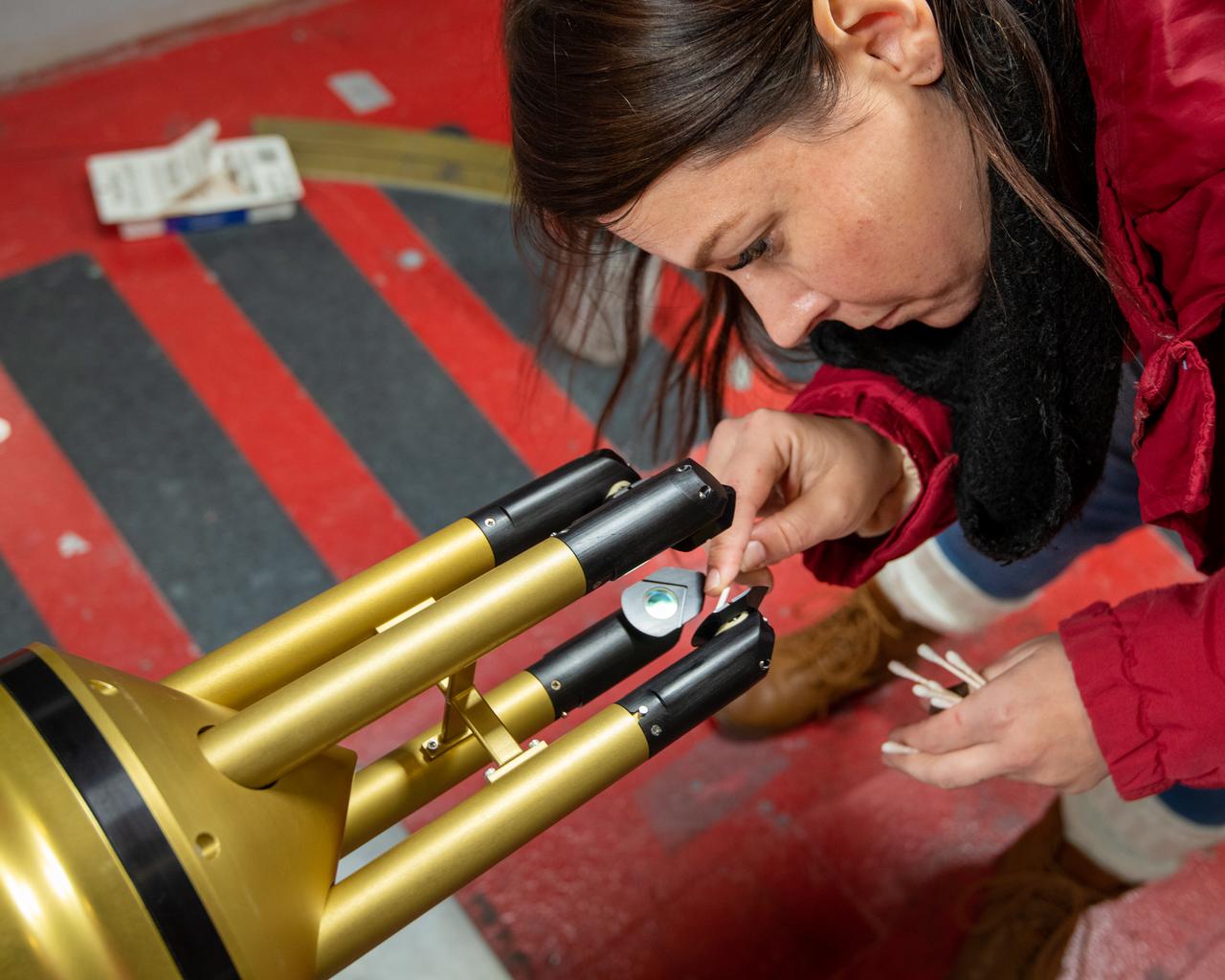
NASA Glenn’s Propulsion Systems Lab (PSL) is conducting research to characterize ice crystal clouds that can create a hazard to aircraft engines in certain conditions. With specialized equipment, scientists can create a simulated ice crystal cloud with the set of bars in the back spraying out a mist. The red area includes lasers, which measure the intensity of the cloud and a series of probes to measure everything from humidity to air pressure. The isokinetic probe (in gold) samples particles and the robotic arm (in orange) has a test tube on the end that catches ice particles for further measuring. NASA Glenn’s PSL is the only place in the world which can create these kind of ice crystal cloud conditions.
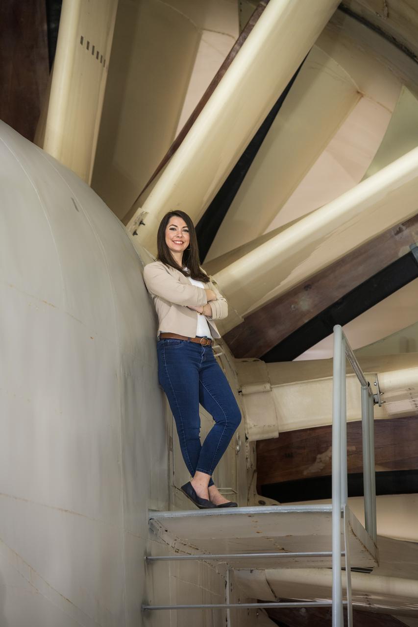
Emily Timko, featured in a Faces of NASA article, poses in the IRT (Icing Research Tunnel) where she works as a “cloud engineer”. She is a Mechanical Test Engineer and works to create unique water spray conditions that simulate icing clouds in the natural aircraft flight environment. Shown in the photo is a portion of the fan drive motor and fan blades that together drive the air through the wind tunnel.

Emily Timko, featured in a Faces of NASA article, poses in the IRT (Icing Research Tunnel) where she works as a “cloud engineer”. She is a Mechanical Test Engineer and works to create unique water spray conditions that simulate icing clouds in the natural aircraft flight environment. Shown in the photo is a portion of the fan drive motor and fan blades that together drive the air through the wind tunnel.
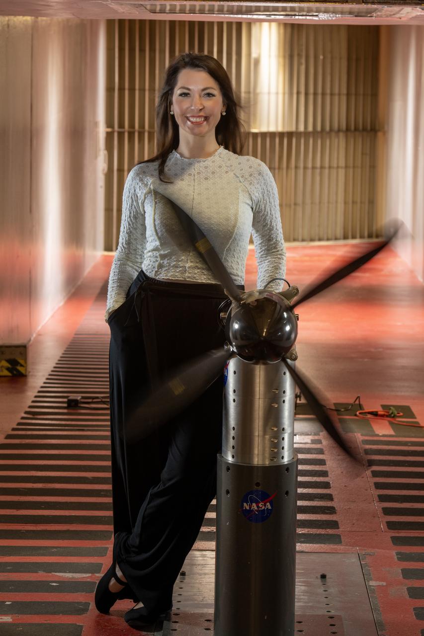
Emily Timko, featured in a Faces of NASA article, poses in the IRT (Icing Research Tunnel) where she works as a “cloud engineer”. She is a Mechanical Test Engineer and works to create unique water spray conditions that simulate icing clouds in the natural aircraft flight environment. Shown in the photo is a test article of a rotating propeller configuration that the IRT researchers are investigating ice accretion with.
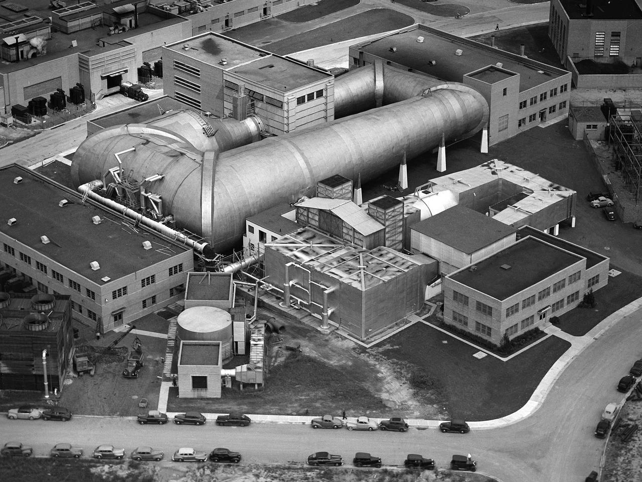
This aerial photograph shows the entire original wind tunnel complex at the National Advisory Committee for Aeronautics (NACA) Aircraft Engine Research Laboratory. The large Altitude Wind Tunnel (AWT) at the center of the photograph dominates the area. The Icing Research Tunnel to the right was incorporated into the lab’s design to take advantage of the AWT’s powerful infrastructure. The laboratory’s first supersonic wind tunnel was added to this complex just prior to this September 1945 photograph. The AWT was the nation’s only wind tunnel capable of studying full-scale engines in simulated flight conditions. The AWT’s test section and control room were within the two-story building near the top of the photograph. The exhauster equipment used to thin the airflow and the drive motor for the fan were in the building to the right of the tunnel. The unique refrigeration equipment was housed in the structure to the left of the tunnel. The Icing Research Tunnel was an atmospheric tunnel that used the AWT’s refrigeration equipment to simulate freezing rain inside its test section. A spray bar system inside the tunnel was originally used to create the droplets. The 18- by 18-inch supersonic wind tunnel was built in the summer of 1945 to take advantage of the AWT’s powerful exhaust system. It was the lab’s first supersonic tunnel and could reach Mach 1.91. Eventually the building would house three small supersonic tunnels, referred to as the “stack tunnels” because of the vertical alignment. The two other tunnels were added to this structure in 1949 and 1951.
The National Advisory Committee for Aeronautics (NACA) Lewis Flight Propulsion Laboratory conducted an extensive icing research program in the late 1940s that included studies in the Icing Research Tunnel and using specially modified aircraft. One facet of this program was the investigation of the effects of icing on turbojets. Although jet engines allowed aircraft to pass through inclement weather at high rates of speed, ice accumulation was still a concern. The NACA’s B-24M Liberator was initially reconfigured with a General Electric I-16 engine installed in the aircraft’s waist compartment with an air scoop and spray nozzles to produce the artificial icing conditions. The centrifugal engine appeared nearly impervious to the effects of icing. Axial-flow jet engines, however, were much more susceptible to icing damage. The inlet guide vanes were particularly vulnerable, but the cowling’s leading edge, the main bearing supports, and accessory housing could also ice up. If pieces of ice reached the engine’s internal components, the compressor blades could be damaged. To study this phenomenon, a Westinghouse 24C turbojet, seen in this photograph, was installed under the B-24M’s right wing. In January 1948 flight tests of the 24C in icing conditions began. Despite ice buildup into the second stage of the compressor, the engine was able to operate at takeoff speeds. Researchers found the ice on the inlet vanes resulted in half of the engine’s decreased performance.

These compressors inside the Refrigeration Building at the National Advisory Committee for Aeronautics (NACA) Aircraft Engine Research Laboratory were used to generate cold temperatures in the Altitude Wind Tunnel (AWT) and Icing Research Tunnel. The AWT was a large facility that simulated actual flight conditions at high altitudes. The two primary aspects of altitude simulation are the reduction of the air pressure and the decrease of temperature. The Icing Research Tunnel was a smaller facility in which water droplets were added to the refrigerated air stream to simulate weather conditions that produced ice buildup on aircraft. The military pressured the NACA to complete the tunnels quickly so they could be of use during World War II. The NACA engineers struggled with the design of this refrigeration system, so Willis Carrier, whose Carrier Corporation had pioneered modern refrigeration, took on the project. The Carrier engineers devised the largest cooling system of its kind in the world. The system could lower the tunnels’ air temperature to –47⁰ F. The cooling system was powered by 14 Carrier and York compressors, seen in this photograph, which were housed in the Refrigeration Building between the two wind tunnels. The compressors converted the Freon 12 refrigerant into a liquid. The refrigerant was then pumped into zig-zag banks of cooling coils inside the tunnels’ return leg. The Freon absorbed heat from the airflow as it passed through the coils. The heat was transferred to the cooling water and sent to the cooling tower where it was dissipated into the atmosphere.
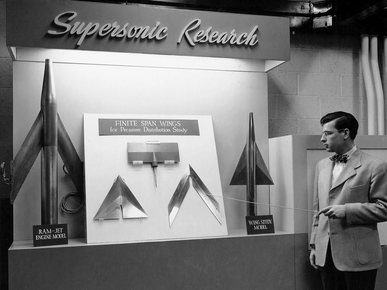
On March 22, 1946, 250 members of the Institute of Aeronautical Science toured the NACA’s Aircraft Engine Research Laboratory. NACA Chairman Jerome Hunsaker and Secretary John Victory were on hand to brief the attendees in the Administration Building before the visited the lab’s test facilities. At each of the twelve stops, researchers provided brief presentations on their work. Topics included axial flow combustors, materials for turbine blades, engine cooling, icing prevention, and supersonic flight. The laboratory reorganized itself in October 1945 as World War II came to an end to address newly emerging technologies such as the jet engine, rockets, and high-speed flight. While design work began on what would eventually become the 8- by 6-Foot Supersonic Wind Tunnel, NACA Lewis quickly built several small supersonic tunnels. These small facilities utilized the Altitude Wind Tunnel’s massive air handling equipment to generate high-speed airflow. The display seen in this photograph was set up in the building that housed the first of these wind tunnels. Eventually the building would contain three small supersonic tunnels, referred to as the “stack tunnels” because of the vertical alignment. The two other tunnels were added to this structure in 1949 and 1951. The small tunnels were used until the early 1960s to study the aerodynamic characteristics of supersonic inlets and exits.
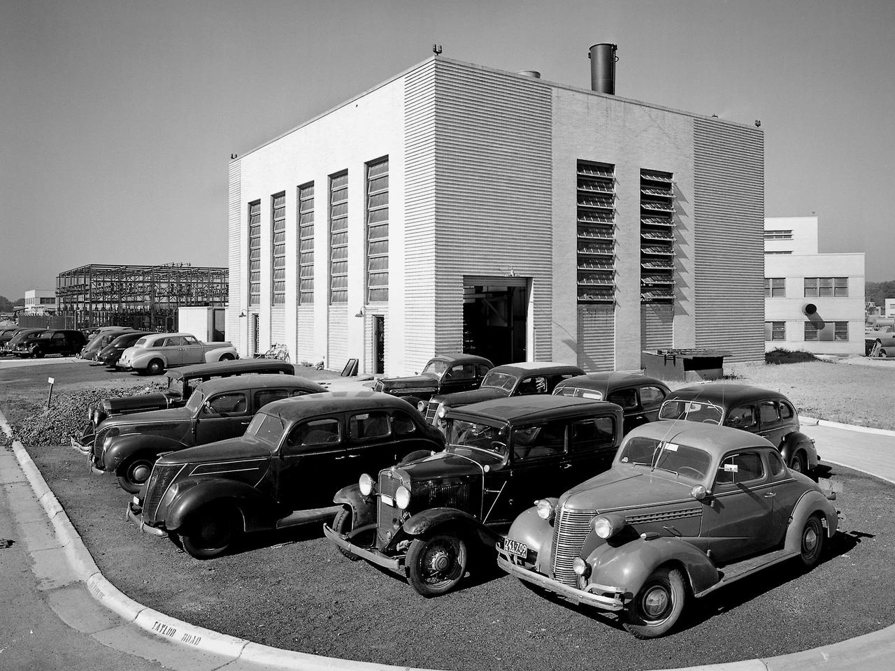
The Steam Plant at the National Advisory Committee for Aeronautics (NACA) Aircraft Engine Research Laboratory supplies steam to the major test facilities and office buildings. Steam is used for the Icing Research Tunnel's spray system and the Engine Research Building’s desiccant air dryers. In addition, its five boilers supply heat to various buildings and the cafeteria. Schirmer-Schneider Company built the $141,000 facility in the fall of 1942, and it has been in operation ever since.
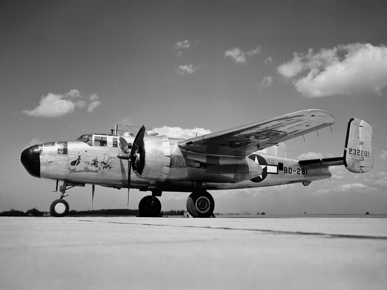
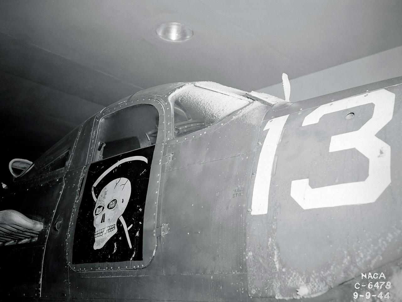
In 1946 the Lewis Flight Propulsion Laboratory became the NACA’s official icing research center. In addition to the Icing Research Tunnel, the lab possessed several aircraft modified for icing work, including a Consolidated B-24M Liberator and a North American XB-25E Mitchell, seen here. The XB-25E’s frequent engine fires allegedly resulted in its “Flamin’ Maimie” nickname. The aircraft’s nose art, visible in this photograph, includes a leather-jacketed mechanic with an extinguisher fleeing a fiery woman. North American developed the B-25 in the mid-1930s as a transport aircraft, but it was hurriedly reconfigured as a medium bomber for World War II. This XB-25E was a single prototype designed in 1942 specifically to test an exhaust gas ice prevention system developed by NACA researcher Lewis Rodert. The system circulated the engines’ hot bleed air to the wings, windshield, and tail. The XB-25E was utilized at the NACA’s Ames Aeronautical Laboratory for two years before being transferred to Cleveland in July 1944. NACA Lewis mechanics modified the aircraft further by installing electrical heating in the front fuselage, propellers, inboard sing, cowls, and antennae. Lewis pilots flew the B-24M and XB-25E into perilous weather conditions all across the country to study both deicing technologies and the physics of ice-producing clouds. These dangerous flights led to advances in weather sensing instruments and flight planning.
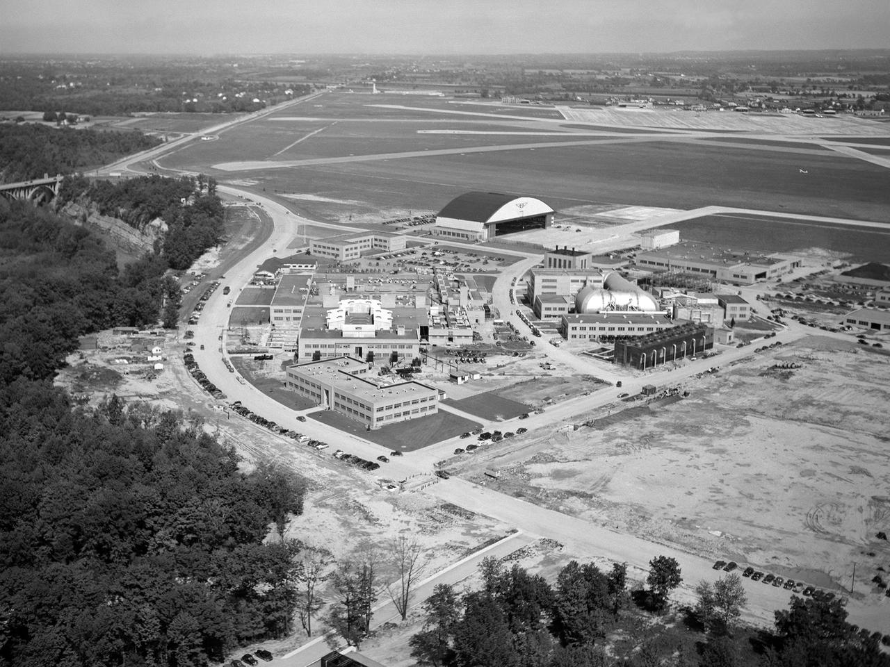
The National Advisory Committee for Aeronautics (NACA) Lewis Flight Propulsion Laboratory in Cleveland, Ohio as seen from the west in May 1946. The Cleveland Municipal Airport is located directly behind. The laboratory was built in the early 1940s to resolve problems associated with aircraft engines. The initial campus contained seven principal buildings: the Engine Research Building, hangar, Fuels and Lubricants Building, Administration Building, Engine Propeller Research Building, Altitude Wind Tunnel, and Icing Research Tunnel. These facilities and their associated support structures were located within an area occupying approximately one-third of the NACA’s property. After World War II ended, the NACA began adding new facilities to address different problems associated with the newer, more powerful engines and high speed flight. Between 1946 and 1955, four new world-class test facilities were built: the 8- by 6-Foot Supersonic Wind Tunnel, the Propulsion Systems Laboratory, the Rocket Engine Test Facility, and the 10- by 10-Foot Supersonic Wind Tunnel. These large facilities occupied the remainder of the NACA’s semicircular property. The Lewis laboratory expanded again in the late 1950s and early 1960s as the space program commenced. Lewis purchased additional land in areas adjacent to the original laboratory and acquired a large 9000-acre site located 60 miles to the west in Sandusky, Ohio. The new site became known as Plum Brook Station.
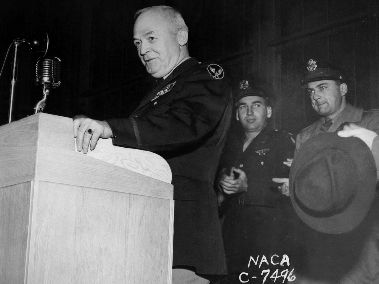
General Henry “Hap” Arnold, Commander of the US Army Air Forces during World War II, addresses the staff at the National Advisory Committee for Aeronautics (NACA) Aircraft Engine Research Laboratory on November 9, 1944. Arnold told the employees assembled in the hangar, “You’ve got a dual task. You’ve got a job ahead of you to keep the army and the navy air forces equipped with the finest equipment that you can for this war. You also have the job of looking forward into the future and starting now those developments, those experiments, that are going to keep us in our present situation—ahead of the world in the air. And that is quite a large order, and I leave it right in your laps.” Arnold served on the NACA’s Executive Committee in Washington from 1938 to 1944 and had been a strong advocate for the creation of the new engine research facility in Cleveland. Arnold believed in continual research and development. He pressed the nation’s aviation leaders to pursue the new jet engine technology, while simultaneously pushing to increase the performance of the nation’s largest piston engine for the B–29 Superfortress program. The general’s hectic wartime agenda limited his visit to the Cleveland laboratory to just a few hours, but he toured several of the NACA’s new test facilities including the Static Jet Propulsion Laboratory, the Icing Research Tunnel, and a B–24 Liberator in the hangar.
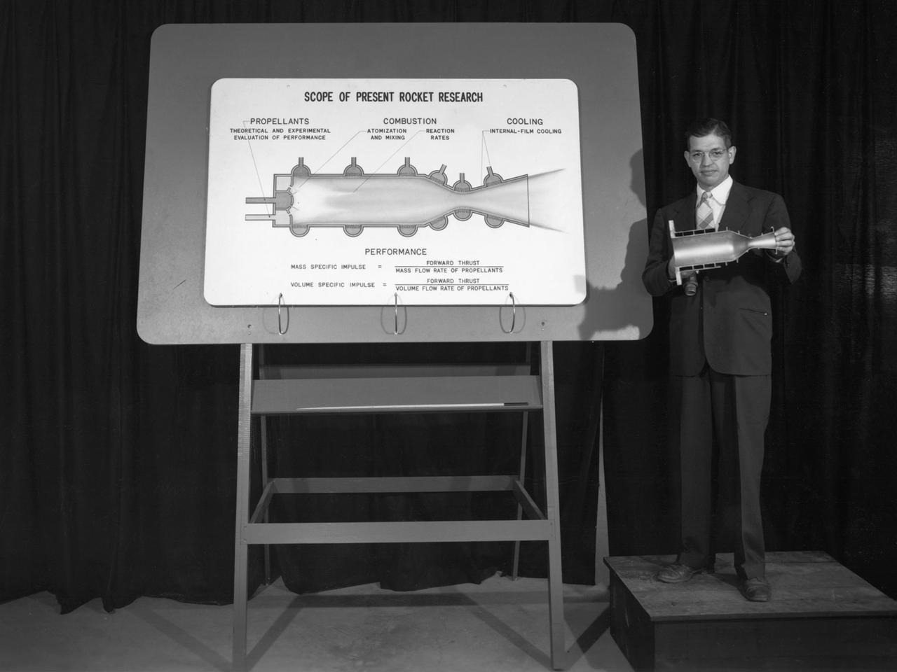
Researcher John Sloop briefs visitors on his latest rocket engine research during the 1947 Inspection at the National Advisory Committee for Aeronautics (NACA) Lewis Flight Propulsion Laboratory. The NACA had been hosting annual Aircraft Engineering Conferences, better known as Inspections, since 1926. Individuals from the manufacturing industry, military, and university settings were invited to tour the NACA laboratories. There were a series of stops on the tour, mostly at test facilities, where researchers would brief the group on the latest efforts in their particular field. The Inspections grew in size and scope over the years and by the mid-1940s required multiple days. The three-day 1947 Inspection was the first time the event was held at NACA Lewis. Over 800 scientists, industrialists, and military leaders attended the three-day event. Talks were given at the Altitude Wind Tunnel, Four Burner Area, Engine Research Building, and other facilities. An array of topics were discussed, including full-scale engine testing, ramjets, axial-flow compressors, turbojets, fuels, icing, and materials. The NACA Lewis staff and their families were able to view the same presentations after the Inspection was over. Sloop, a researcher in the Fuels and Thermodynamics Division, briefed visitors on NACA Lewis’ early research in rocket engine propellants, combustion, and cooling. This early NACA Lewis work led to the development of liquid hydrogen as a viable propellant in the late 1950s.
![Astronaut Neil Armstrong examines a Vertical and Short Takeoff and Landing test setup in the 9- by 15-Foot Low Speed Wind Tunnel at the National Aeronautics and Space Administration (NASA) Lewis Research Center. Armstrong spent February 6, 1970 at Lewis attending technical meetings and touring some facilities. Just six months after Armstrong had returned from the moon looming agency budget cuts were already a concern in his comments. He noted that NASA had to “find a balanced approach…and [make] aggressive use of available facilities.” Armstrong spent four months at the center as a research pilot in 1955. Armstrong had served as a Navy pilot during the Korean War then earned a degree in aeronautical engineering at Purdue University. He was recruited by Lewis while at Purdue and began at the center shortly after graduation. During his brief tenure in Cleveland Armstrong served as both a test pilot and research engineer, primarily involved with icing research. In his role as research pilot Armstrong also flew a North American F-82 Twin Mustang over the ocean near Wallops Island to launch small instrumented rockets from high altitudes down into the atmosphere to obtain high Mach numbers. After four months in Cleveland a position opened up at what is today the Dryden Flight Research Center. Armstrong’s career in Cleveland officially ended on June 30, 1955.](https://images-assets.nasa.gov/image/GRC-1970-C-00473/GRC-1970-C-00473~medium.jpg)
Astronaut Neil Armstrong examines a Vertical and Short Takeoff and Landing test setup in the 9- by 15-Foot Low Speed Wind Tunnel at the National Aeronautics and Space Administration (NASA) Lewis Research Center. Armstrong spent February 6, 1970 at Lewis attending technical meetings and touring some facilities. Just six months after Armstrong had returned from the moon looming agency budget cuts were already a concern in his comments. He noted that NASA had to “find a balanced approach…and [make] aggressive use of available facilities.” Armstrong spent four months at the center as a research pilot in 1955. Armstrong had served as a Navy pilot during the Korean War then earned a degree in aeronautical engineering at Purdue University. He was recruited by Lewis while at Purdue and began at the center shortly after graduation. During his brief tenure in Cleveland Armstrong served as both a test pilot and research engineer, primarily involved with icing research. In his role as research pilot Armstrong also flew a North American F-82 Twin Mustang over the ocean near Wallops Island to launch small instrumented rockets from high altitudes down into the atmosphere to obtain high Mach numbers. After four months in Cleveland a position opened up at what is today the Dryden Flight Research Center. Armstrong’s career in Cleveland officially ended on June 30, 1955.
Installation of the 2D-S (2-Dimensional Stereo) optical array probe made by Stratton Park Engineering Company (SPEC)
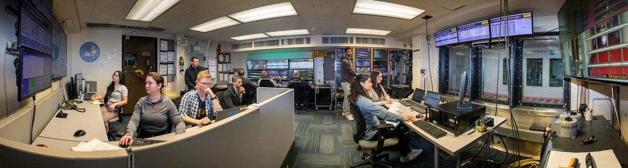
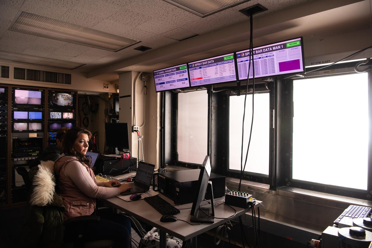
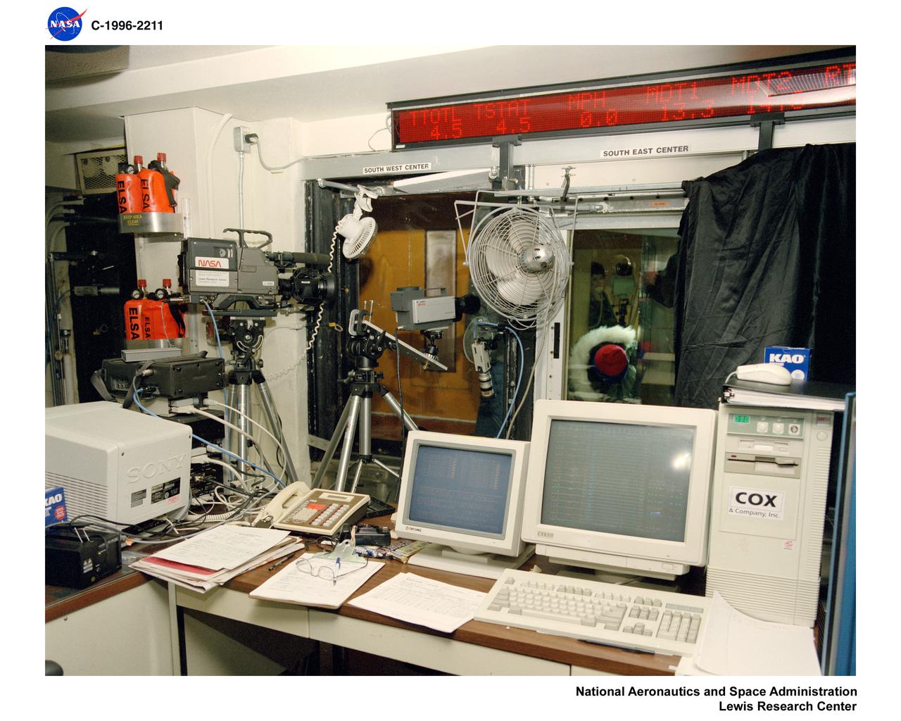
Panorama of the IRT engineering and ice cloud calibration team in the control room. Shown on the left are the data and system engineers. In the center with their backs to the camera are the wind tunnel operators who control the wind speed and super cooled water flow. In the center right of the photo is the video recording system and the test engineers. On the right side the test section can be see though the wind and the TV screen shows the pray bars that create the icing cloud.