
An inlet duct lowered into the 20-foot diameter test section of the Altitude Wind Tunnel at the National Advisory Committee for Aeronautics (NACA) Lewis Flight Propulsion Laboratory. Engines and hardware were prepared in the facility’s shop area. The test articles were lifted by a two-rail Shaw box crane through the high-bay and the second-story test chamber before being lowered into the test section. Technicians then spent days or weeks hooking up the supply lines and data recording telemetry. The engines were mounted on wingspans that stretched across the test section. The wingtips attached to the balance frame’s trunnions, which could adjust the angle of attack. The balance frame included six devices that recorded data and controlled the engine. The measurements were visible in banks of manometer boards next to the control room. Photographs recorded the pressure levels in the manometer tubes, and the computing staff manually converted the data into useful measurements. A mechanical pulley system was used to raise and lower the tunnel’s large clamshell lid into place. The lid was sealed into place using hand-turned locks accessible from the viewing platform. The lid had viewing windows above and below the test article, which permitted the filming and visual inspection of the tests.
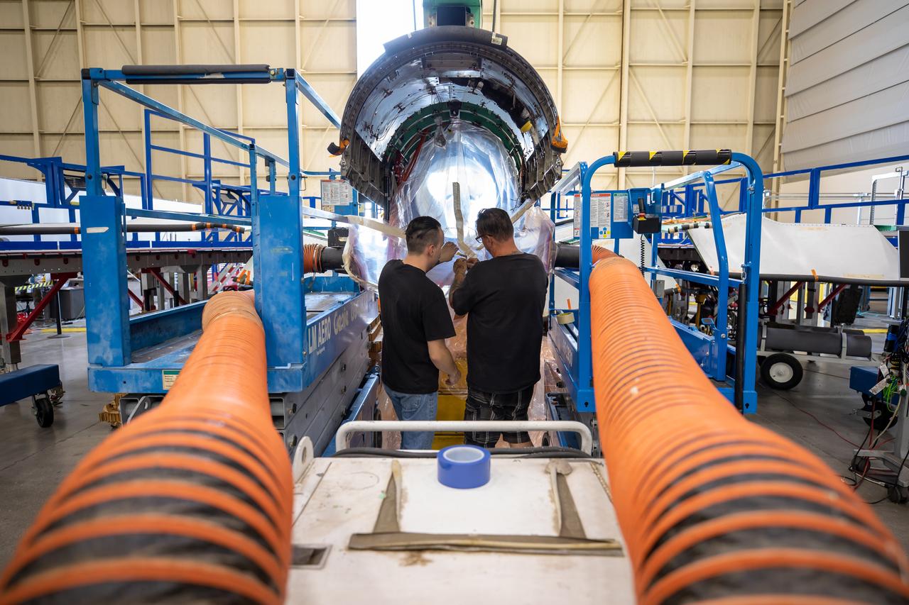
This image shows the extensive ventilation system that has been placed adjacent to the X-59 during the recent painting of the aircraft’s engine inlet. Once the aircraft build and ground testing are complete, the X-59 airplane will begin flight testing, working towards demonstrating the ability to fly supersonic while reducing the loud sonic boom to a quiet sonic thump and help enable commercial supersonic air travel over land.
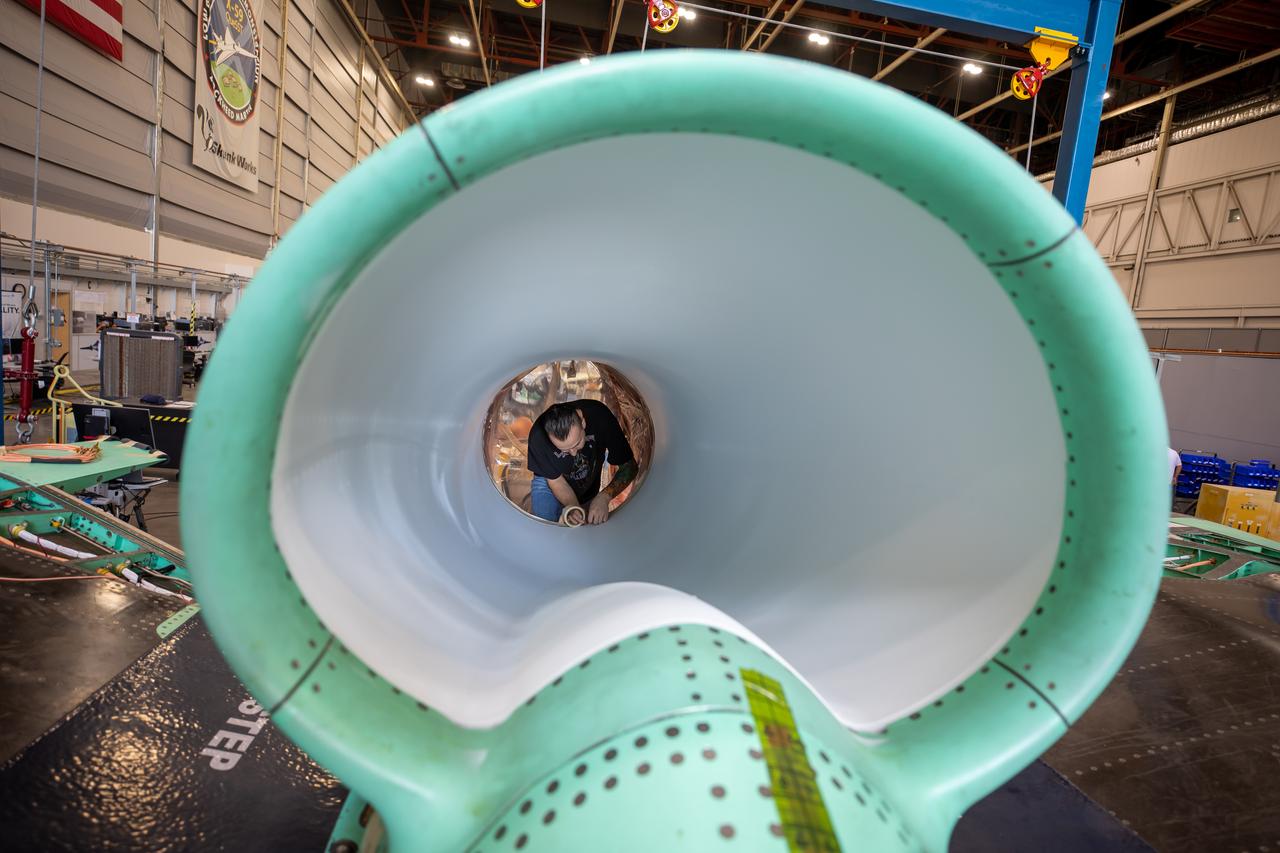
This is an up-close view of the X-59’s engine inlet – fresh after being painted. The 13-foot F414-GE-100 engine will be placed inside the inlet bringing the X-59 aircraft one step closer to completion. Once fully assembled, the X-59 aircraft will begin flight operations, working toward demonstration of the ability to fly supersonic while reducing the loud sonic boom to a quiet sonic thump, helping to enable commercial supersonic air travel over land.

Title: W-8 Fan Acoustic Casing Treatment Test on the Source Diagnostic Test Rotor Alone Hardware Program: Advanced Air Vehicles Program (AAVP) Project: Advanced Air Transport Technology (AATT) Sub-project: Aircraft Noise Reduction (ANR) Weekly Highlight: · Acoustic Casing Treatment Testing Completed in the W-8 Single Stage Axial Compressor Facility: Testing of Acoustic Casing Treatments on the Source Diagnostic Test (SDT) rotor alone hardware which had begun in early January was completed on Thursday, February 16th. Four different over-the-rotor acoustic casing treatment concepts were tested along with two baseline configurations. Testing included steady-aerodynamic measurements of fan performance, hotfilm turbulence measurements, and inlet acoustic measurements with an in-duct array. These measurements will be used to assess the aerodynamic and acoustic impact of fan acoustic casing treatments on a high bypass ratio fan at TRL 3. This test was the last of 3 planned tests of potential over-the-rotor acoustic casing treatments. The first treatment test was completed in the Normal Incidence Tube (NIT) at Langley Research Center (LaRC) in Fall 2015 and the second was completed on the Advanced Noise Control Fan (ANCF) in the Aero-Acoustic Propulsion Laboratory (AAPL) in Winter 2016. This work is supported by the Aircraft Noise Reduction (ANR) subproject of the Advanced Air Transport Technology (AATT) Project. (POC: LTV/ Rick Bozak 3-5160)
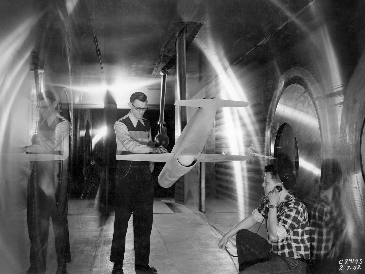
A researcher at the National Advisory Committee for Aeronautics (NACA) Lewis Flight Propulsion Laboratory checks the setup of a RJM-2 ramjet model in the test section of the 8- by 6-Foot Supersonic Wind Tunnel. The 8- by 6 was not only the laboratory’s first large supersonic wind tunnel, but it was also the NACA’s first facility capable of testing an operating engine at supersonic speeds. The 8- by 6-foot tunnel has been used to study engine inlets, fuel injectors, flameholders, exit nozzles, and controls on ramjet and turbojet propulsion systems. The 8-foot wide and 6-foot tall test section consisted of 1-inch thick steel plates with hatches on the floor and ceiling to facilitate the installation of the test article. The two windows seen on the right wall allowed photographic equipment to be set up. The test section was modified in 1956 to accommodate transonic research. NACA engineers drilled 4,700 holes into the test section walls to reduce transonic pressure disturbances and shock waves. NACA Lewis undertook an extensive research program on ramjets in the 1940s using several of its facilities. Ramjets provide a very simple source of propulsion. They are basically a tube which ingests high speed air, ignites it, and then expels the heated air at a significantly higher velocity. Ramjets are extremely efficient and powerful but can only operate at high speeds. Therefore, they require a booster rocket or aircraft drop to accelerate them to high speeds before they can operate.
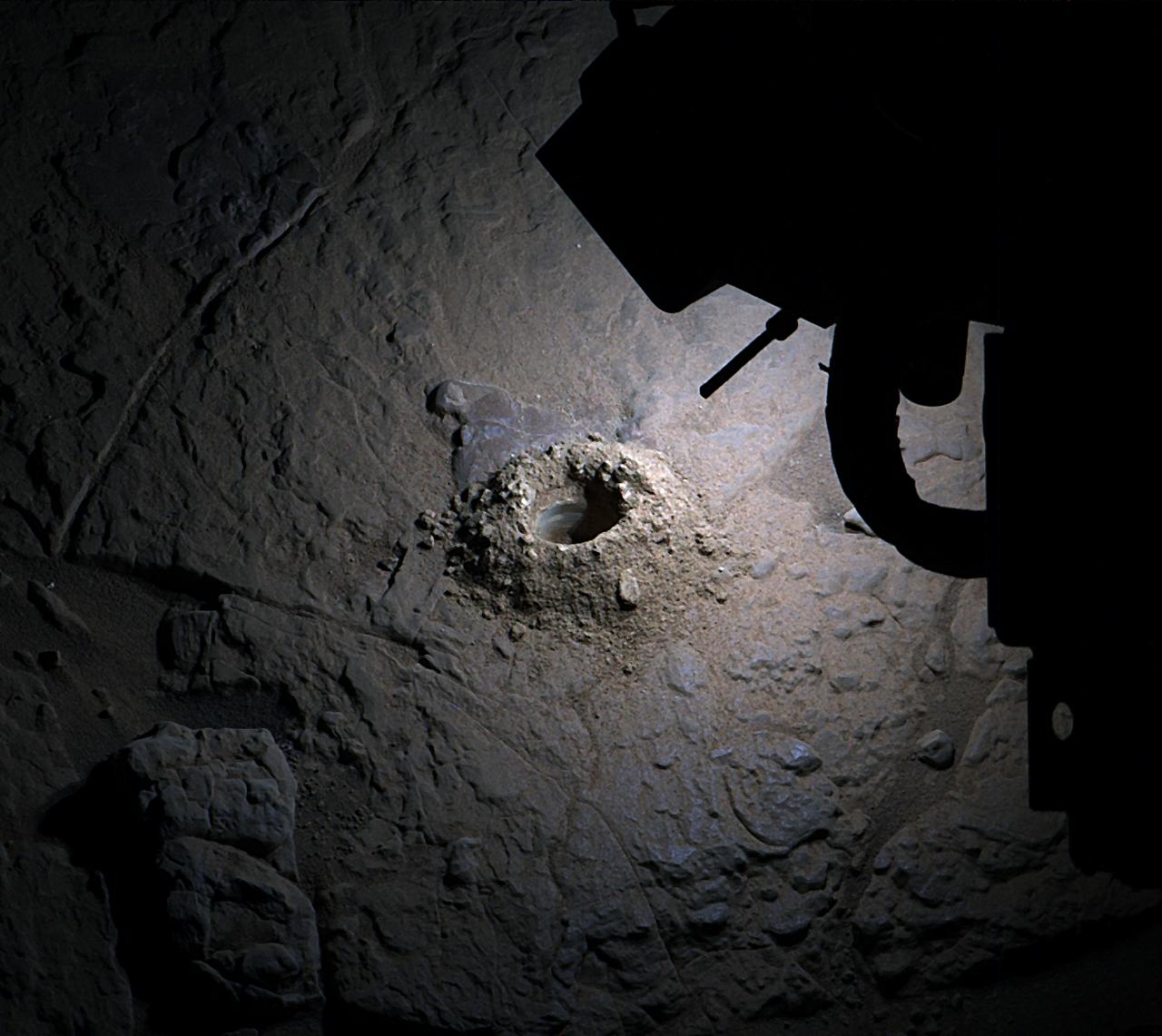
NASA’s Curiosity Mars rover used LED lights on the end of its robotic arm to create this rare nighttime view of the Red Planet’s surface on Dec. 6, 2025, the 4,740th Martian day, or sol, of the rover’s mission. The LED lights are part of the Mars Hand Lens Imager, or MAHLI, a camera on the end of Curiosity’s robotic arm. The image was captured by the Mast Camera, or Mastcam, on the rover’s mast, or “head.” On occasion, scientists have used MAHLI’s LED lights to illuminate areas deep in shadow during the day, such as the insides of drill holes and the inlet tubes leading to instruments in the rover’s belly. Much earlier in the mission, the Curiosity team used these LEDs at night to look for layering or other features in drill hole walls that would help them understand a rock’s composition. Since the mission changed its drilling method, the drill holes have come out too rough and dusty to see any such details. After drilling a rock target nicknamed “Nevado Sajama” on Nov. 13, 2025 (Sol 4,718), the team noticed the drill hole walls were smooth enough to try looking for layers and decided to try illuminating the drill hole at night. This drill hole was made during Curiosity’s exploration of a region full of geologic formations called boxwork, which crisscross the surface for miles and look like giant spiderwebs when viewed from space. Curiosity was built by NASA’s Jet Propulsion Laboratory, which is managed by Caltech in Pasadena, California. JPL leads the mission on behalf of NASA’s Science Mission Directorate in Washington as part of NASA’s Mars Exploration Program portfolio. Malin Space Science Systems in San Diego built and operates both Mastcam and MAHLI. To learn more about Curiosity, visit: science.nasa.gov/mission/msl-curiosity