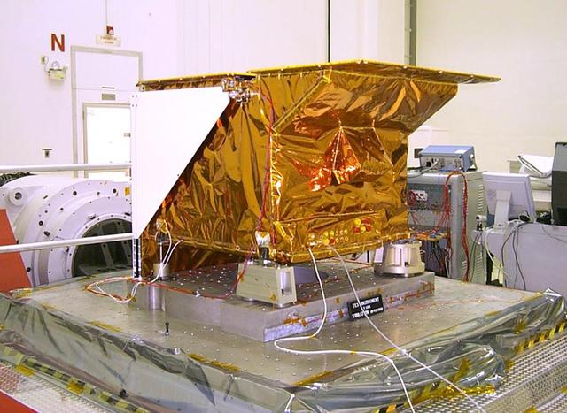
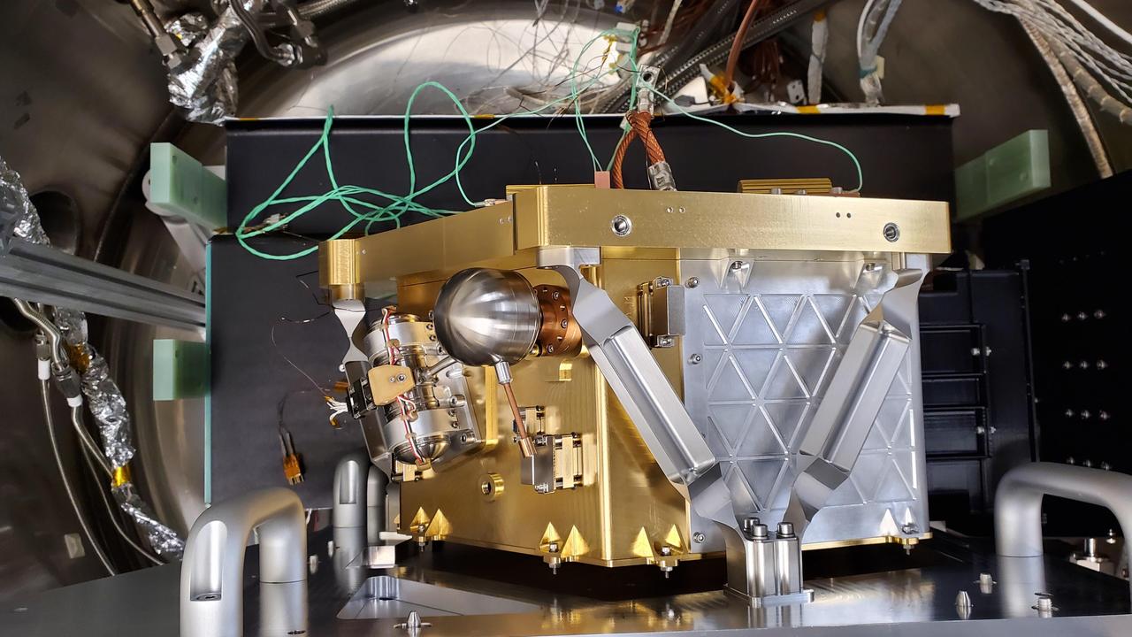
The Diviner Instrument prior to shipment. Diviner is one of seven instruments aboard NASA LRO Mission.
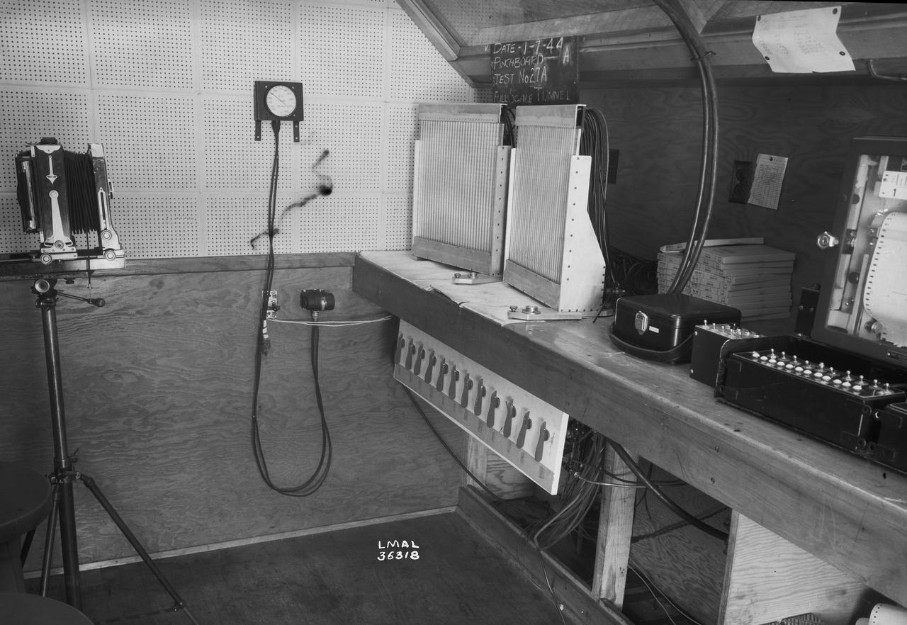
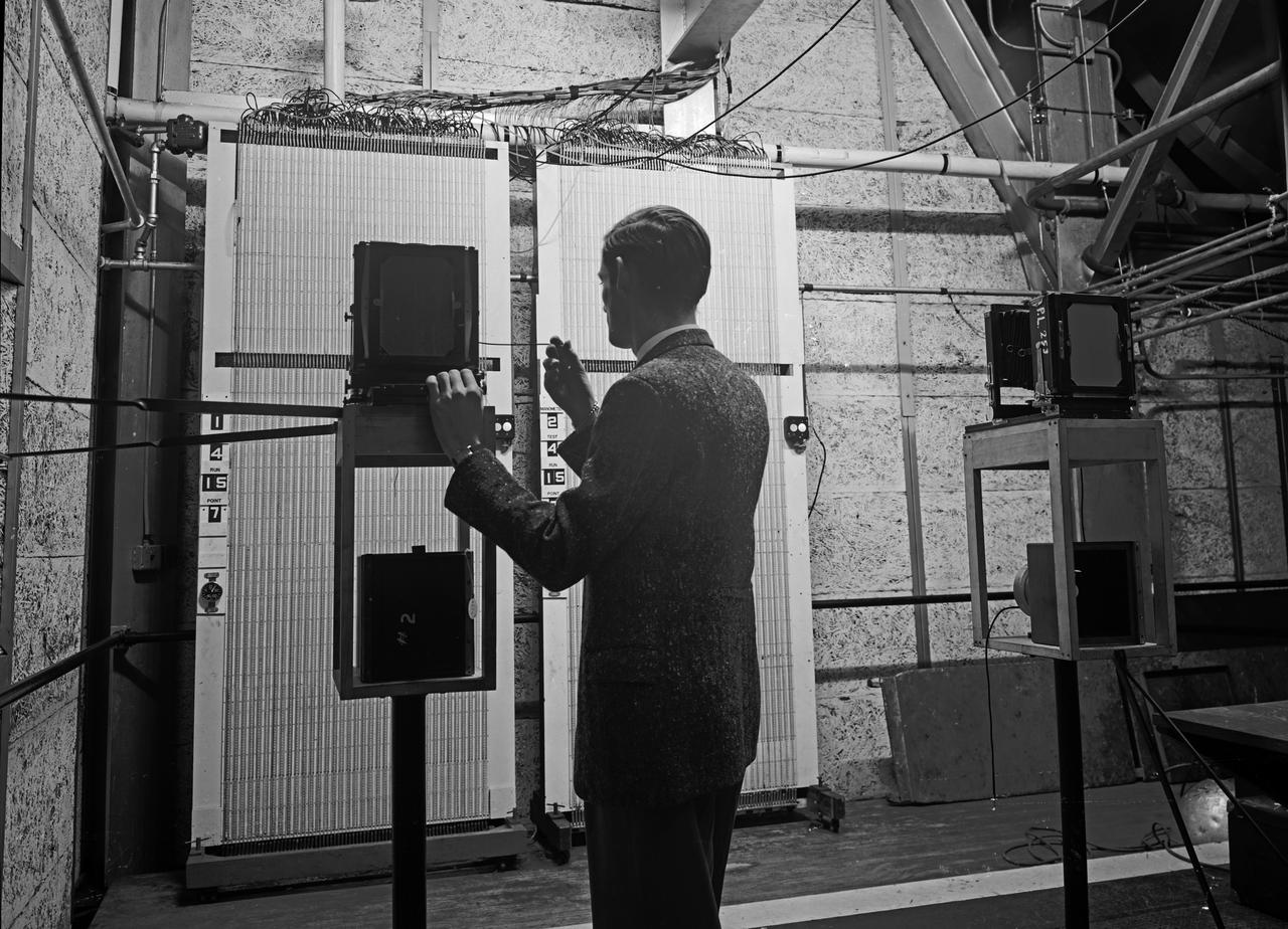
Instrumentation in Full Scale Tunnel
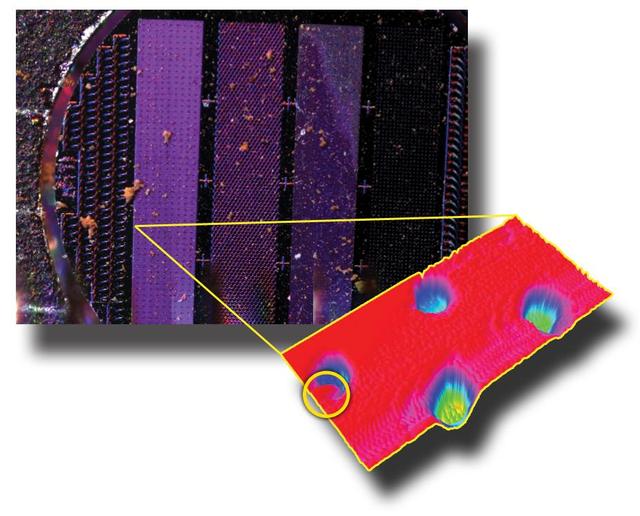
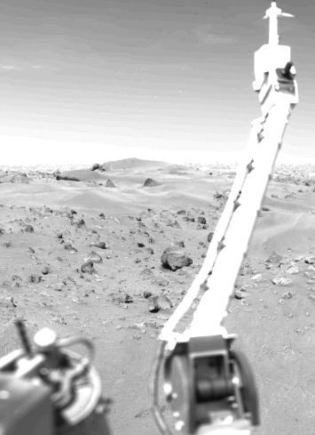
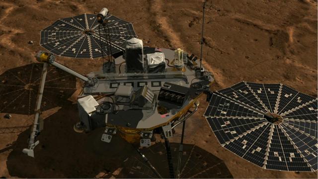
Images from Phoenix MECA Instruments
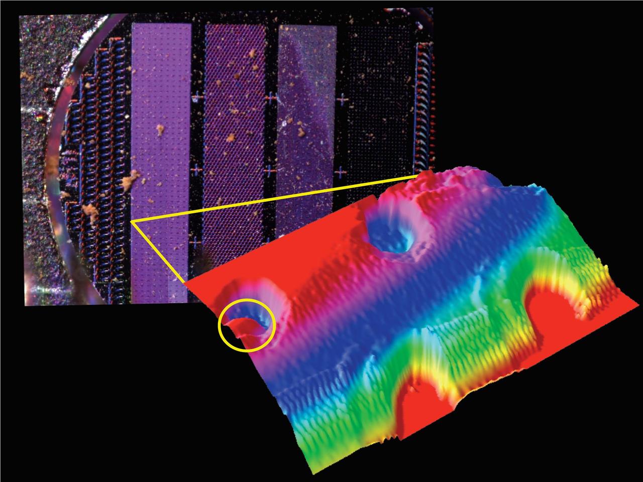
Images from Phoenix MECA Instruments
The Meteorology Instrument on Viking Lander 1 http://photojournal.jpl.nasa.gov/catalog/PIA00392
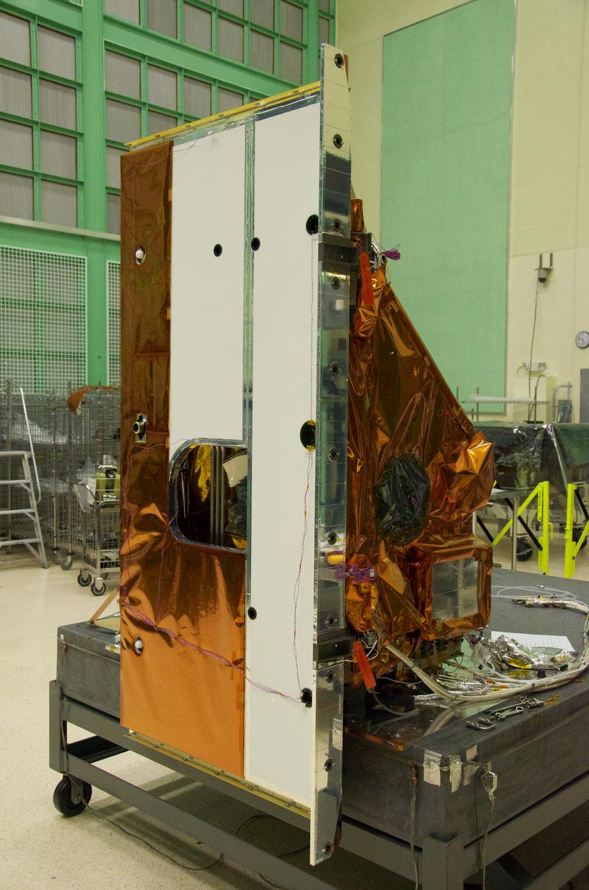
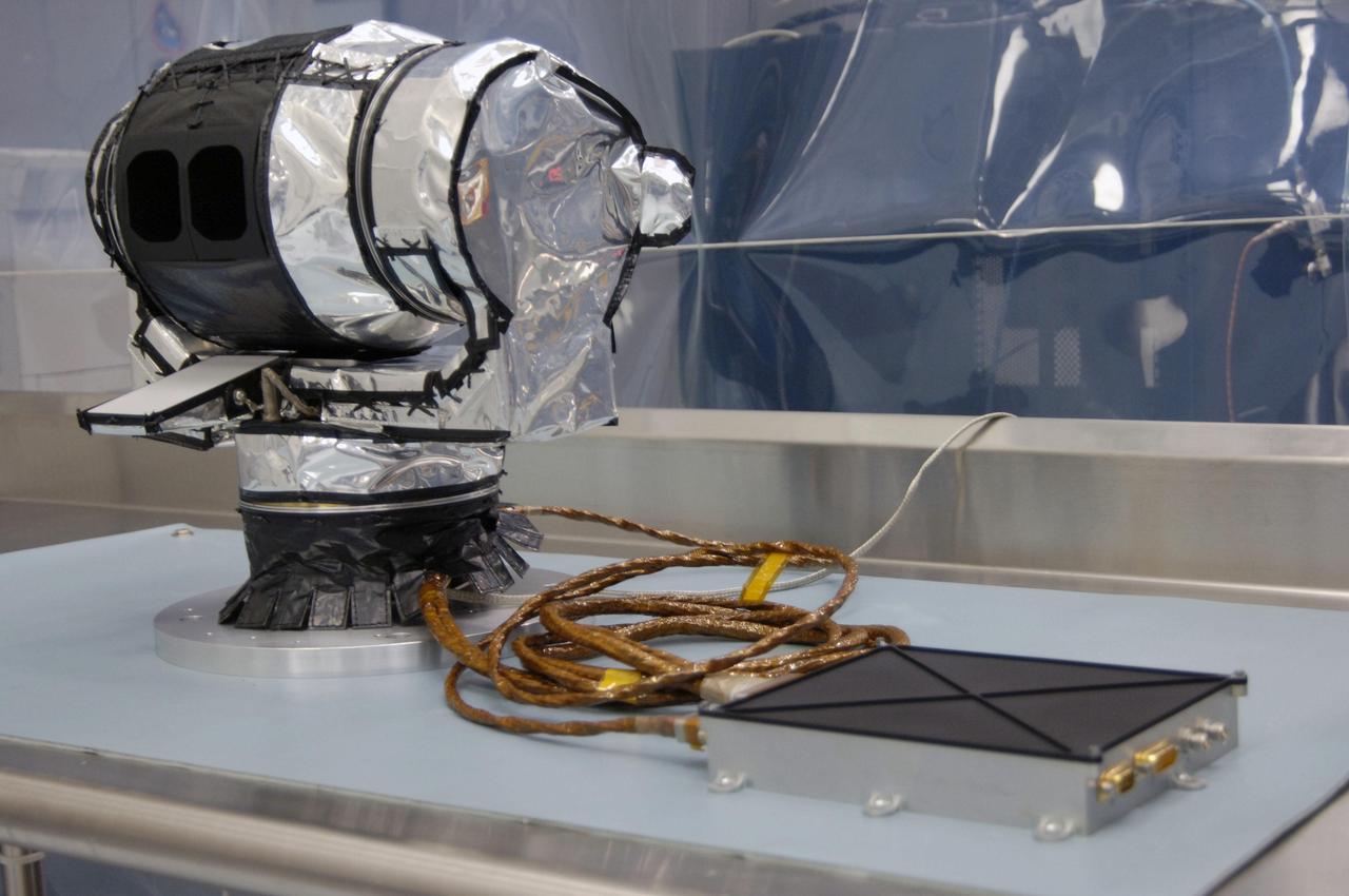
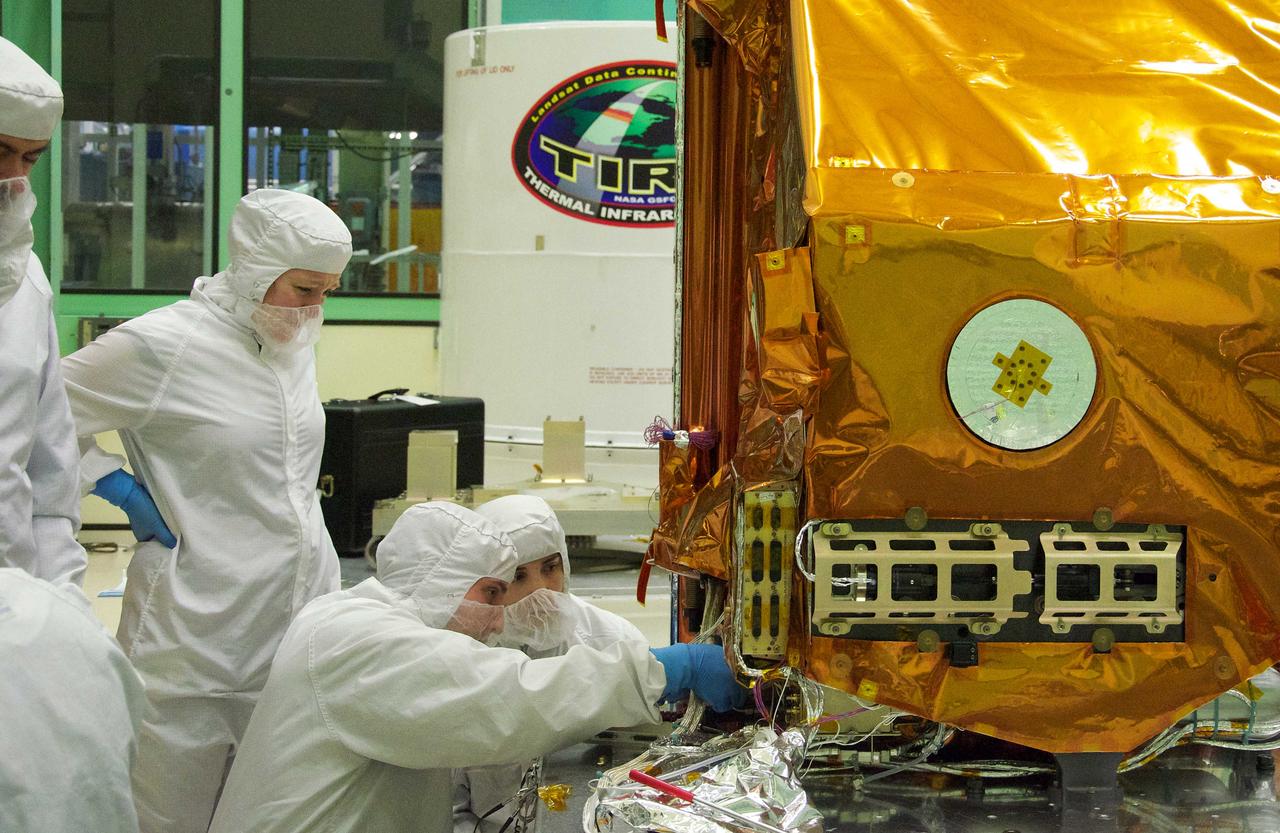
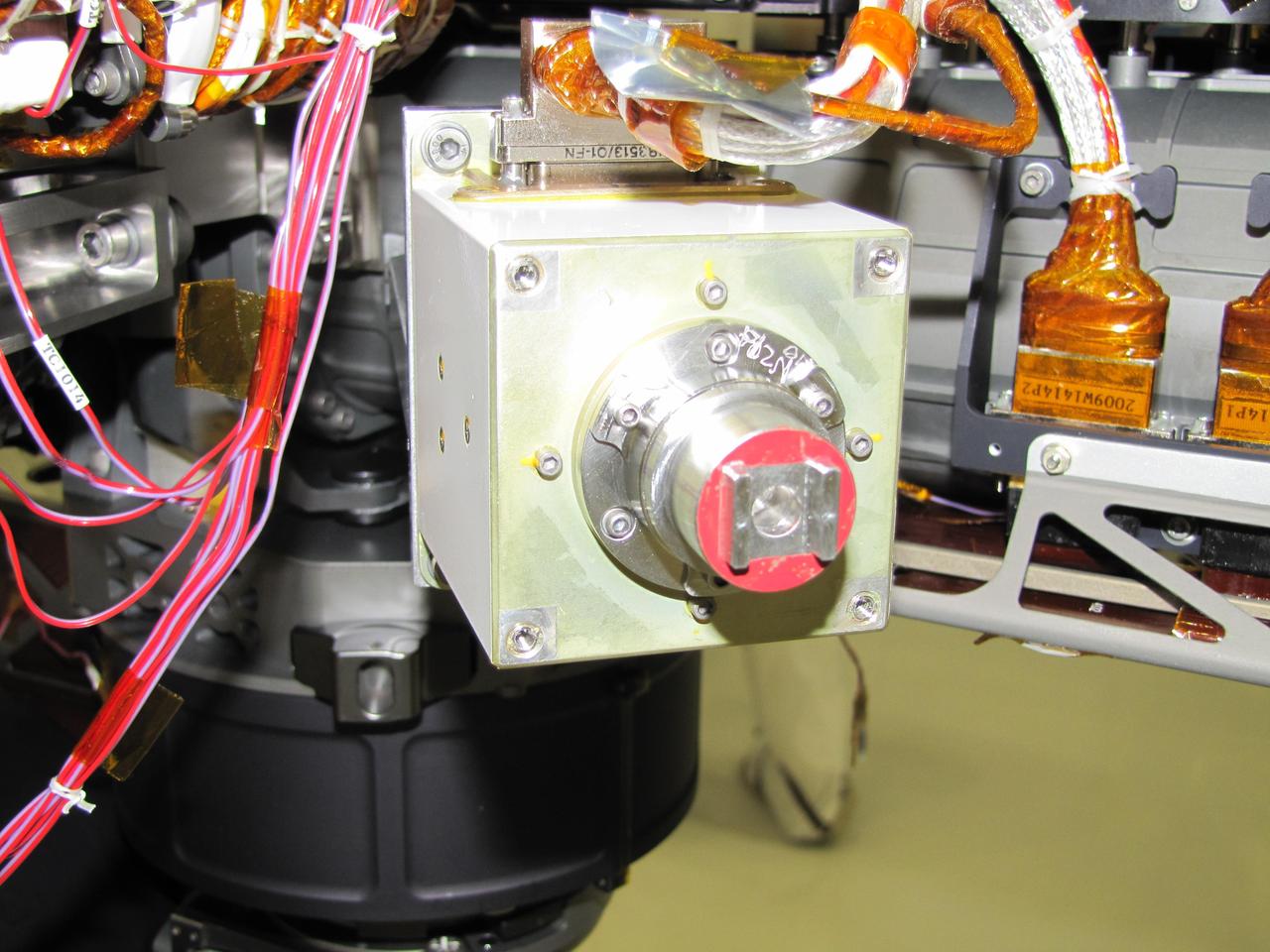
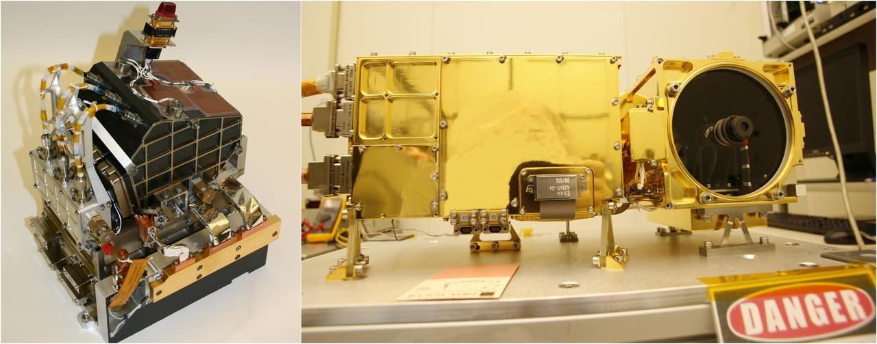
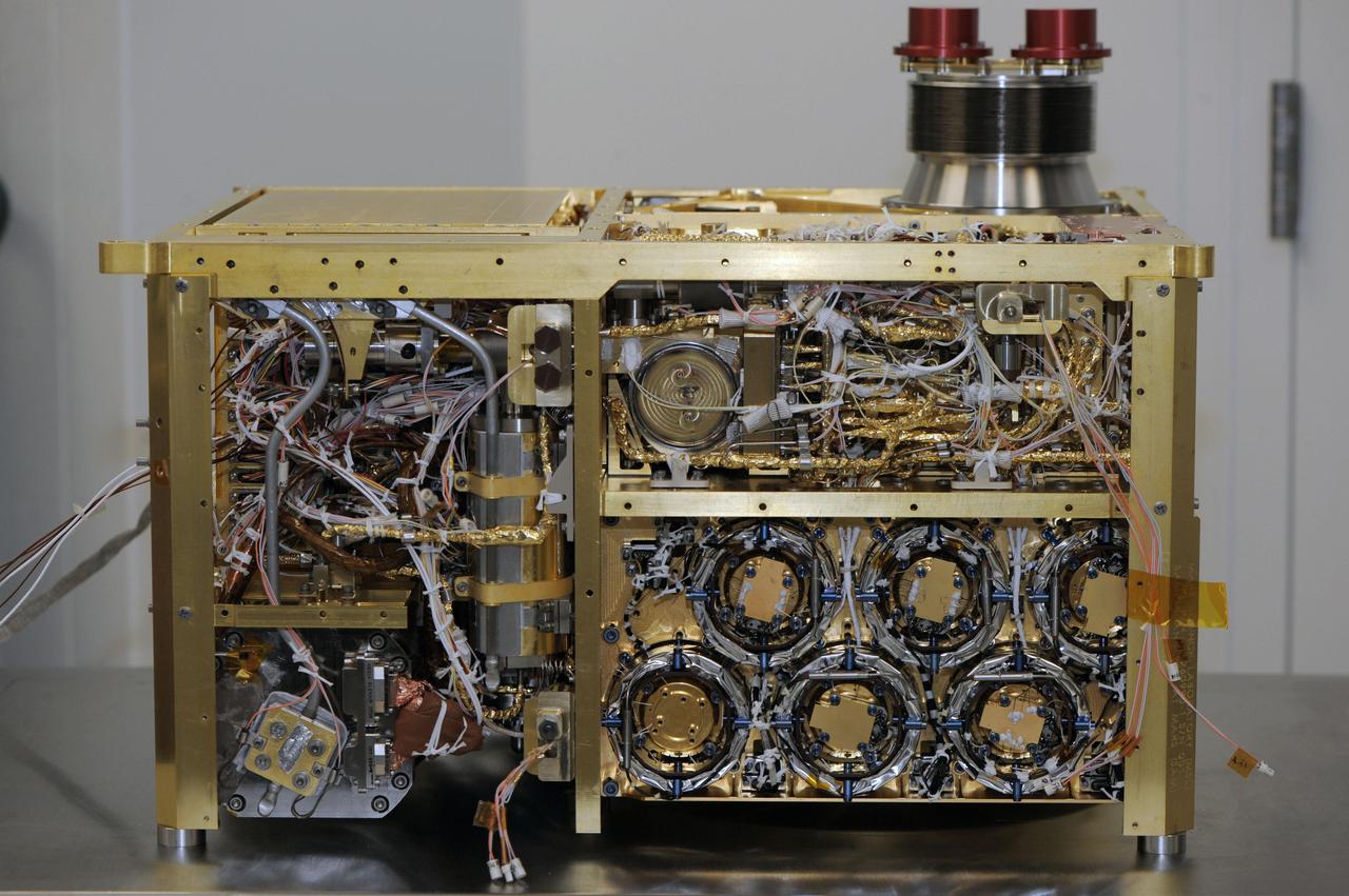
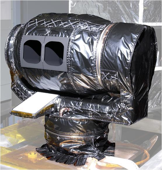
The Thermal Infrared Sensor (TIRS) will fly on the next Landsat satellite, the Landsat Data Continuity Mission (LDCM). The right side of the instrument is what's called the 'nadir side,' that's the side that points toward Earth when the instrument is in space. The black circle visible on the right side is where the optics for the instrument are located. In that area are the lens and the detectors. The white area is a radiator that radiates heat to keep the telescope and the detector cool. The black hole on the white area on the left is what the satellite operators point to deep space when they calibrate the instrument to the cold temperatures of space. TIRS was built on an accelerated schedule at NASA's Goddard Space Flight Center, Greenbelt, Md. and will now be integrated into the LDCM spacecraft at Orbital Science Corp. in Gilbert, Ariz. The Landsat Program is a series of Earth observing satellite missions jointly managed by NASA and the U.S. Geological Survey. Landsat satellites have been consistently gathering data about our planet since 1972. They continue to improve and expand this unparalleled record of Earth's changing landscapes for the benefit of all. For more information on Landsat, visit: <a href="http://www.nasa.gov/landsat" rel="nofollow">www.nasa.gov/landsat</a> Credit: NASA/GSFC/Rebecca Roth <b><a href="http://www.nasa.gov/audience/formedia/features/MP_Photo_Guidelines.html" rel="nofollow">NASA image use policy.</a></b> <b><a href="http://www.nasa.gov/centers/goddard/home/index.html" rel="nofollow">NASA Goddard Space Flight Center</a></b> enables NASA’s mission through four scientific endeavors: Earth Science, Heliophysics, Solar System Exploration, and Astrophysics. Goddard plays a leading role in NASA’s accomplishments by contributing compelling scientific knowledge to advance the Agency’s mission. <b>Follow us on <a href="http://twitter.com/NASA_GoddardPix" rel="nofollow">Twitter</a></b> <b>Like us on <a href="http://www.facebook.com/pages/Greenbelt-MD/NASA-Goddard/395013845897?ref=tsd" rel="nofollow">Facebook</a></b> <b>Find us on <a href="http://instagrid.me/nasagoddard/?vm=grid" rel="nofollow">Instagram</a></b>
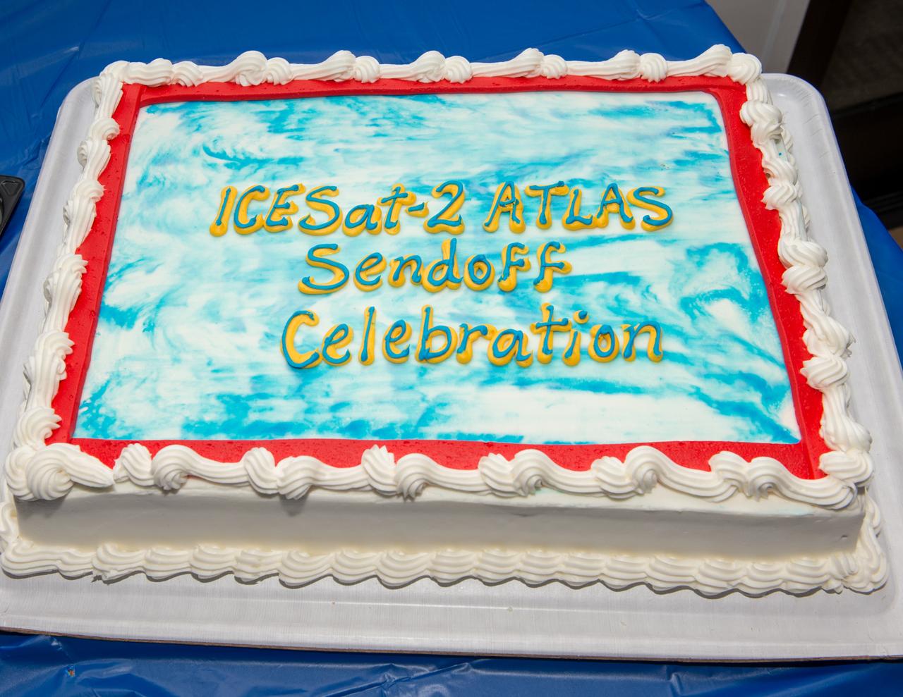
ICESat-2 big send off event for the ATLAS laser instrument at the Goddard Recreation Center

ICESat-2 big send off event for the ATLAS laser instrument at the Goddard Recreation Center
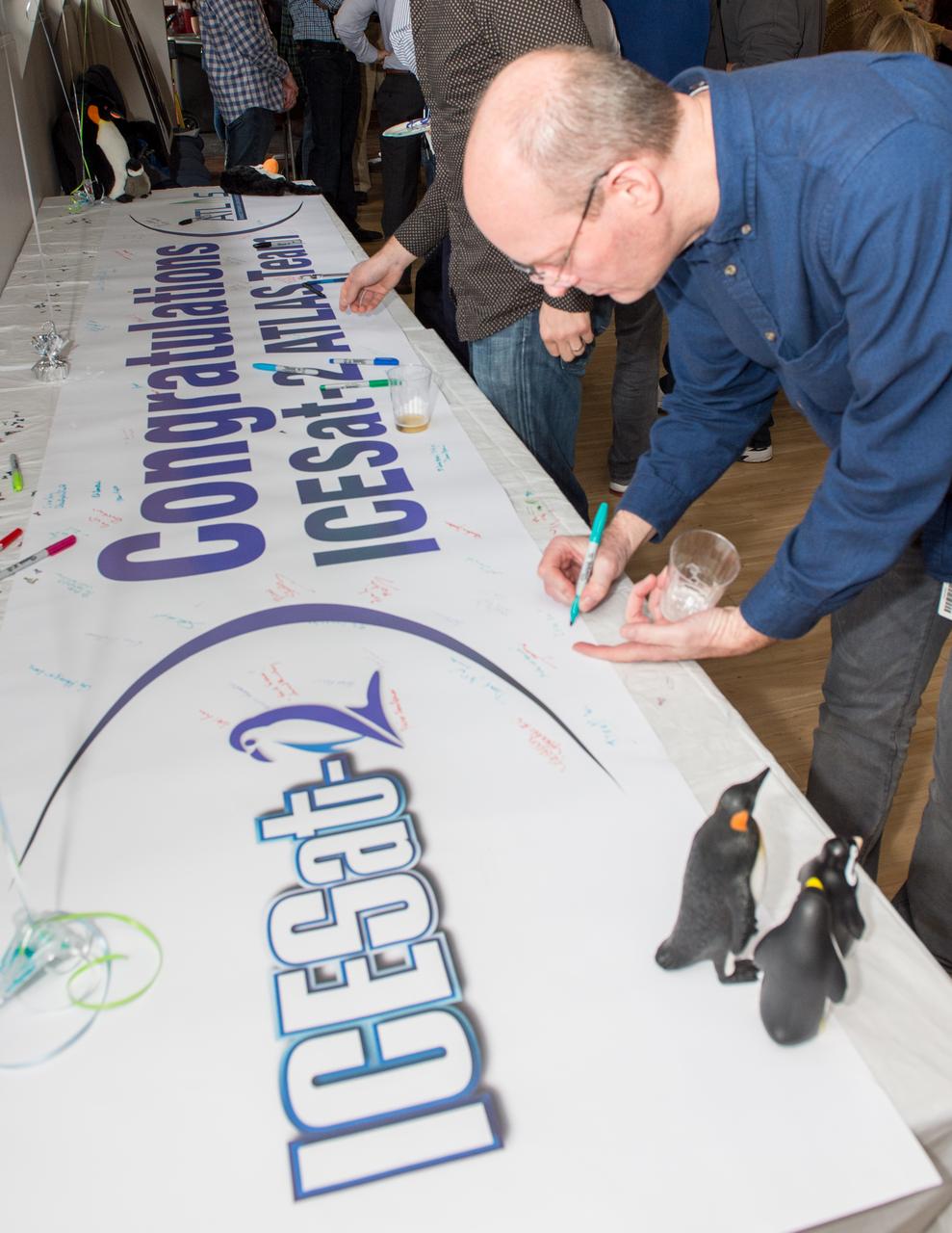
ICESat-2 big send off event for the ATLAS laser instrument at the Goddard Recreation Center
This frame from an animation shows a zoom into the Mars Descent Imager MARDI instrument onboard NASA Phoenix Mars Lander. The Phoenix team will soon attempt to use a microphone on the MARDI instrument to capture sounds of Mars.
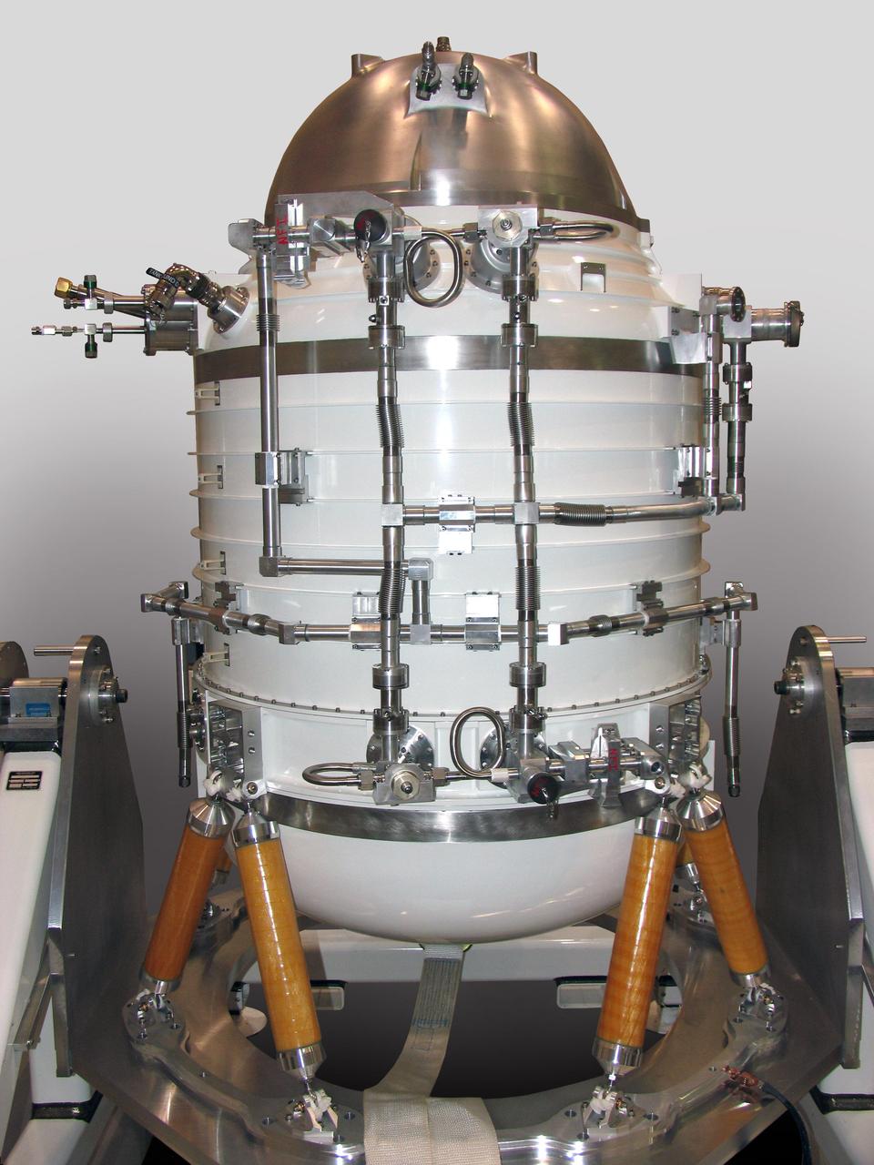
Some say the science instrument on NASA Wide-field Infrared Survey Explorer mission resembles the Star Wars robot R2-D2. The instrument is enclosed in a solid-hydrogen cryostat, which cools the WISE telescope and detectors.
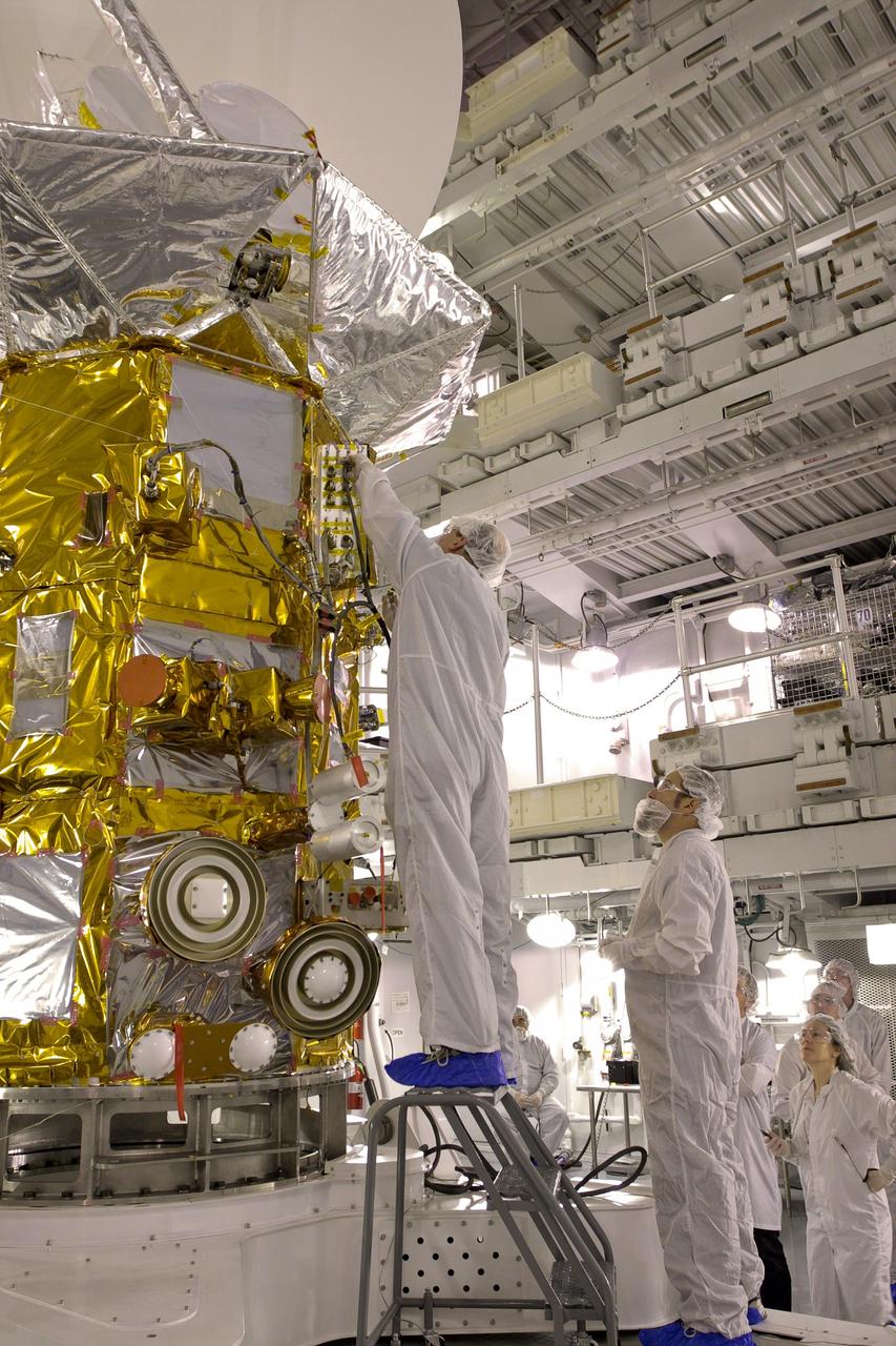
Less than two months before launch, team members conduct their final checks of NASA Aquarius instrument at Vandenberg Air Force Base, Calif. Subsequent final instrument tests will be conducted on the launch pad.
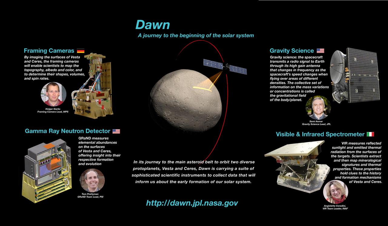
NASA Dawn instrumentation poster, part of the Dawn Mission Art series. http://photojournal.jpl.nasa.gov/catalog/PIA19374
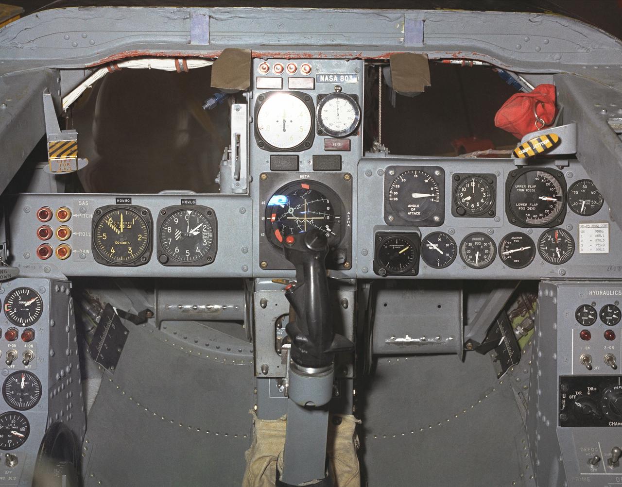
This photo shows the cockpit instrument panel of the M2-F3 Lifting Body.
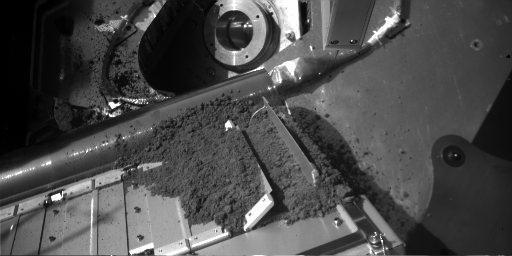
Martian Soil Delivery to Analytical Instrument on Phoenix
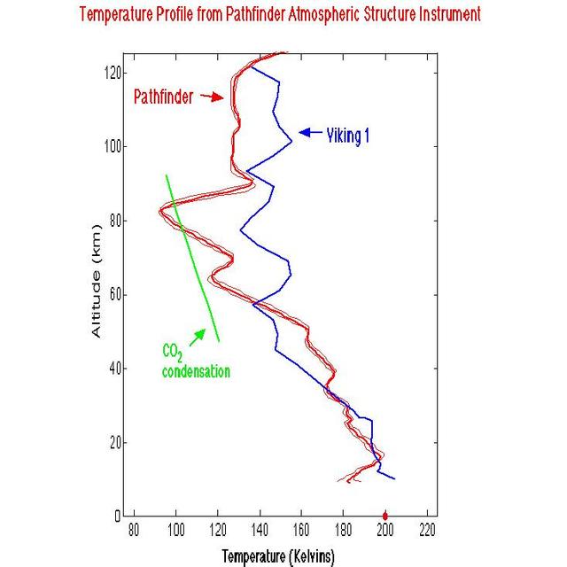
Temperature Profile from Pathfinder Atmospheric Structure Instrument
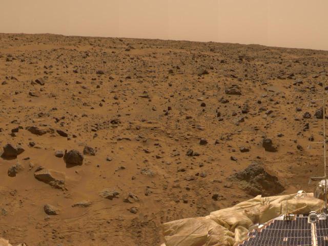
Airbag and ASI/MET Instrument in 360-degree Panorama
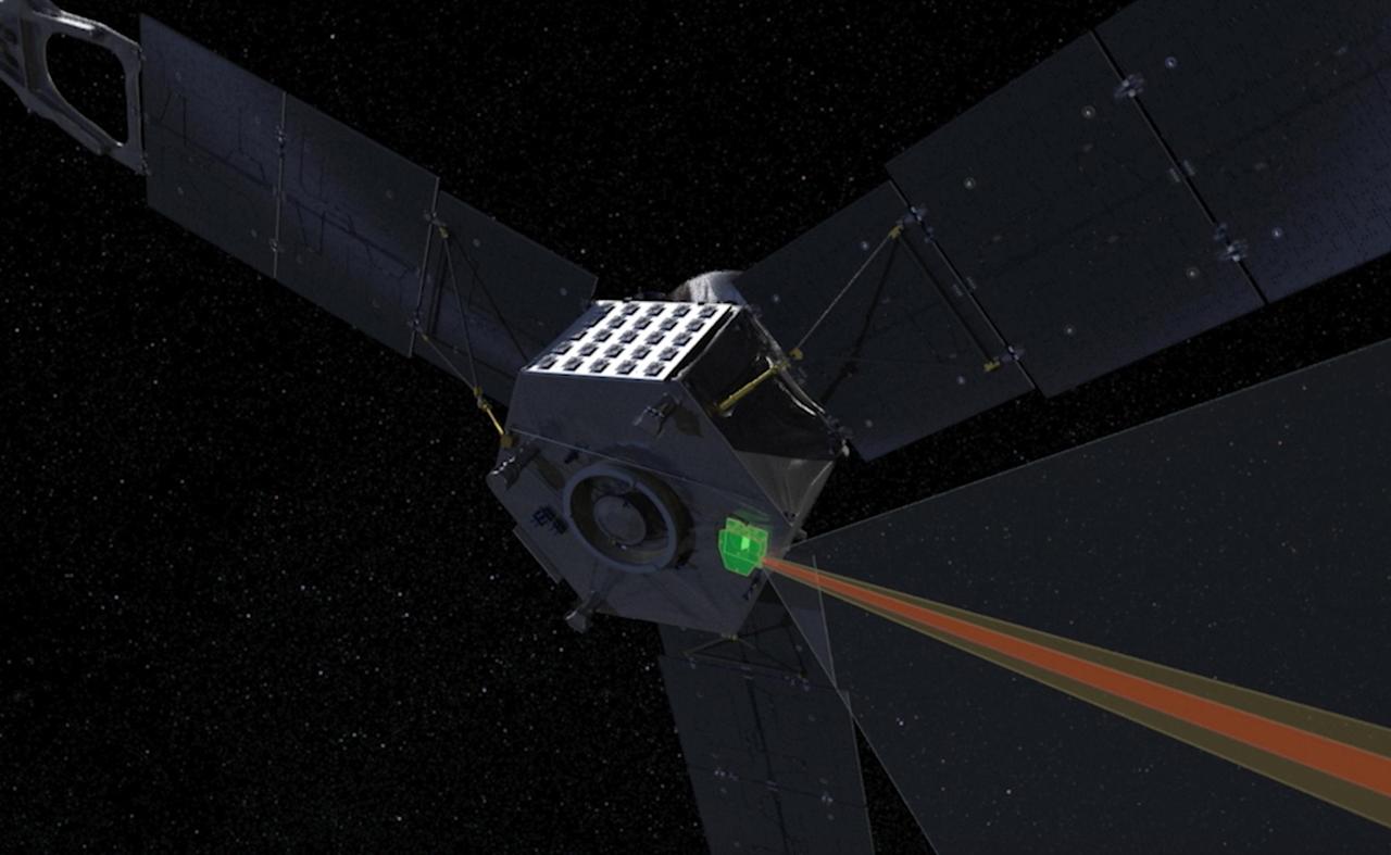
This computer-generated image depicts the Jovian Infrared Auroral Mapper (JIRAM) instrument aboard NASA's Juno spacecraft. The JIRAM instrument measures heat radiated from the planet at an infrared wavelength of around 5 microns. https://photojournal.jpl.nasa.gov/catalog/PIA23594
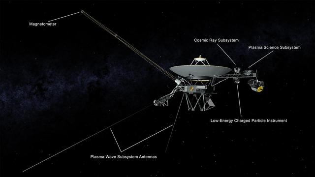
This illustration of NASA's Voyager 2 spacecraft shows the location of the onboard science instruments that are still operating: the magnetometer, the cosmic ray subsystem, the plasma science experiment, the low-energy charged particle instrument and the antennas used by the plasma wave subsystem. https://photojournal.jpl.nasa.gov/catalog/PIA22915
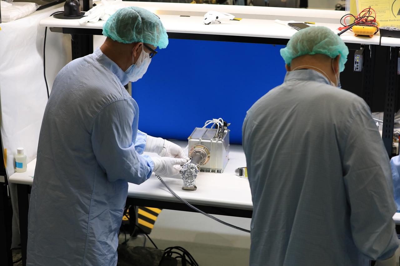
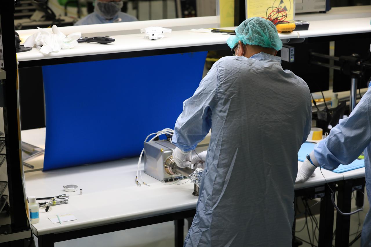
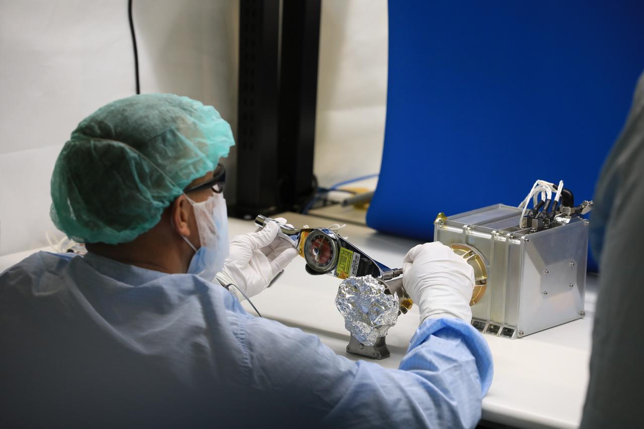
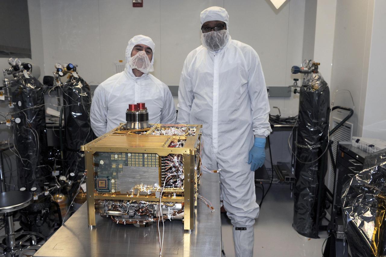
Aleksandra Bogunovic (left) and Veronica Otero (right) look on while Pete Steigner (in the middle) adds a flow tube that will make sure that nitrogen gas flows through the instrument while it's being shipped. The gas will keep contaminating particles from infiltrating the instrument. The Thermal Infrared Sensor (TIRS) will fly on the next Landsat satellite, the Landsat Data Continuity Mission (LDCM). TIRS was built on an accelerated schedule at NASA's Goddard Space Flight Center, Greenbelt, Md. and will now be integrated into the LDCM spacecraft at Orbital Science Corp. in Gilbert, Ariz. The Landsat Program is a series of Earth observing satellite missions jointly managed by NASA and the U.S. Geological Survey. Landsat satellites have been consistently gathering data about our planet since 1972. They continue to improve and expand this unparalleled record of Earth's changing landscapes for the benefit of all. For more information on Landsat, visit: <a href="http://www.nasa.gov/landsat" rel="nofollow">www.nasa.gov/landsat</a> Credit: NASA/GSFC/Rebecca Roth <b><a href="http://www.nasa.gov/audience/formedia/features/MP_Photo_Guidelines.html" rel="nofollow">NASA image use policy.</a></b> <b><a href="http://www.nasa.gov/centers/goddard/home/index.html" rel="nofollow">NASA Goddard Space Flight Center</a></b> enables NASA’s mission through four scientific endeavors: Earth Science, Heliophysics, Solar System Exploration, and Astrophysics. Goddard plays a leading role in NASA’s accomplishments by contributing compelling scientific knowledge to advance the Agency’s mission. <b>Follow us on <a href="http://twitter.com/NASA_GoddardPix" rel="nofollow">Twitter</a></b> <b>Like us on <a href="http://www.facebook.com/pages/Greenbelt-MD/NASA-Goddard/395013845897?ref=tsd" rel="nofollow">Facebook</a></b> <b>Find us on <a href="http://instagrid.me/nasagoddard/?vm=grid" rel="nofollow">Instagram</a></b>
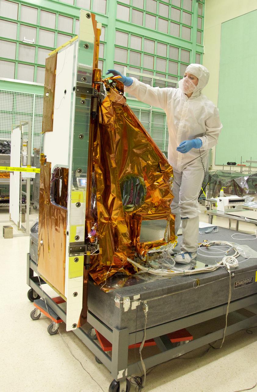
Aleksandra Bogunovic reaches across the instrument to affix the corners of a Multi-Layer Insulation blanket to the TIRS instrument. The Thermal Infrared Sensor (TIRS) will fly on the next Landsat satellite, the Landsat Data Continuity Mission (LDCM). TIRS was built on an accelerated schedule at NASA's Goddard Space Flight Center, Greenbelt, Md. and will now be integrated into the LDCM spacecraft at Orbital Science Corp. in Gilbert, Ariz. The Landsat Program is a series of Earth observing satellite missions jointly managed by NASA and the U.S. Geological Survey. Landsat satellites have been consistently gathering data about our planet since 1972. They continue to improve and expand this unparalleled record of Earth's changing landscapes for the benefit of all. For more information on Landsat, visit: <a href="http://www.nasa.gov/landsat" rel="nofollow">www.nasa.gov/landsat</a> Credit: NASA/GSFC/Rebecca Roth <b><a href="http://www.nasa.gov/audience/formedia/features/MP_Photo_Guidelines.html" rel="nofollow">NASA image use policy.</a></b> <b><a href="http://www.nasa.gov/centers/goddard/home/index.html" rel="nofollow">NASA Goddard Space Flight Center</a></b> enables NASA’s mission through four scientific endeavors: Earth Science, Heliophysics, Solar System Exploration, and Astrophysics. Goddard plays a leading role in NASA’s accomplishments by contributing compelling scientific knowledge to advance the Agency’s mission. <b>Follow us on <a href="http://twitter.com/NASA_GoddardPix" rel="nofollow">Twitter</a></b> <b>Like us on <a href="http://www.facebook.com/pages/Greenbelt-MD/NASA-Goddard/395013845897?ref=tsd" rel="nofollow">Facebook</a></b> <b>Find us on <a href="http://instagrid.me/nasagoddard/?vm=grid" rel="nofollow">Instagram</a></b>
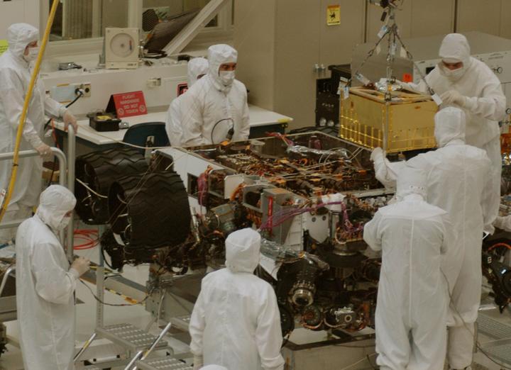
The sensor head on the Alpha Particle X-ray Spectrometer instrument was installed during testing at NASA Jet Propulsion Laboratory. The instrument is part of NASA Curiosity rover.
Engineers check cables on back of Aquarius instrument in the clean room at NASA Jet Propulsion Laboratory in Pasadena, Calif.
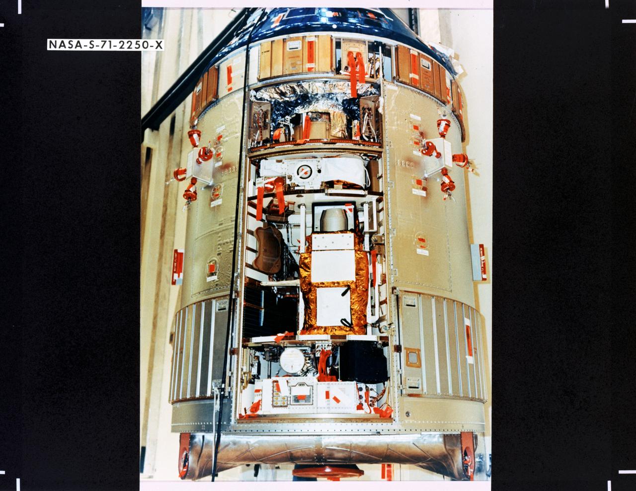
S71-2250X (June 1971) --- A close-up view of the Scientific Instrument Module (SIM) to be flown for the first time on the Apollo 15 lunar landing mission. Mounted in a previously vacant sector of the Apollo Service Module (SM), the SIM carries specialized cameras and instrumentation for gathering lunar orbit scientific data. SIM equipment includes a laser altimeter for accurate measurement of height above the lunar surface; a large-format panoramic camera for mapping, correlated with a metric camera and the laser altimeter for surface mapping; a gamma ray spectrometer on a 25-feet extendible boom; a mass spectrometer on a 21-feet extendible boom; X-ray and alpha particle spectrometers; and a subsatellite which will be injected into lunar orbit carrying a particle and magnetometer, and the S-Band transponder.
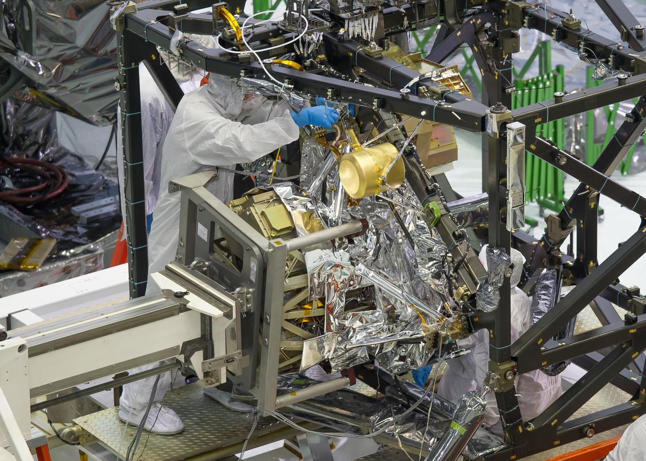
A technician is installing the bolts that will hold the MIRI, or Mid-Infrared Instrument, to the composite Integrated Science Instrument Module (ISIM) structure, or the black frame. The MIRI is attached to a balance beam, called the Horizontal Integration Tool (HIT), hanging from a precision overhead crane. That's the same tool that Hubble engineers used to prepare hardware for its servicing missions. Photo Credit: NASA/Chris Gunn; Text Credit: NASA/Laura Betz ---- Engineers worked meticulously to implant the James Webb Space Telescope's Mid-Infrared Instrument into the ISIM, or Integrated Science Instrument Module, in the cleanroom at NASA's Goddard Space Flight Center in Greenbelt, Md. As the successor to NASA's Hubble Space Telescope, the Webb telescope will be the most powerful space telescope ever built. It will observe the most distant objects in the universe, provide images of the first galaxies formed and see unexplored planets around distant stars. For more information, visit: <a href="http://www.jwst.nasa.gov" rel="nofollow">www.jwst.nasa.gov</a> <b><a href="http://www.nasa.gov/audience/formedia/features/MP_Photo_Guidelines.html" rel="nofollow">NASA image use policy.</a></b> <b><a href="http://www.nasa.gov/centers/goddard/home/index.html" rel="nofollow">NASA Goddard Space Flight Center</a></b> enables NASA’s mission through four scientific endeavors: Earth Science, Heliophysics, Solar System Exploration, and Astrophysics. Goddard plays a leading role in NASA’s accomplishments by contributing compelling scientific knowledge to advance the Agency’s mission. <b>Follow us on <a href="http://twitter.com/NASA_GoddardPix" rel="nofollow">Twitter</a></b> <b>Like us on <a href="http://www.facebook.com/pages/Greenbelt-MD/NASA-Goddard/395013845897?ref=tsd" rel="nofollow">Facebook</a></b> <b>Find us on <a href="http://instagram.com/nasagoddard?vm=grid" rel="nofollow">Instagram</a></b>
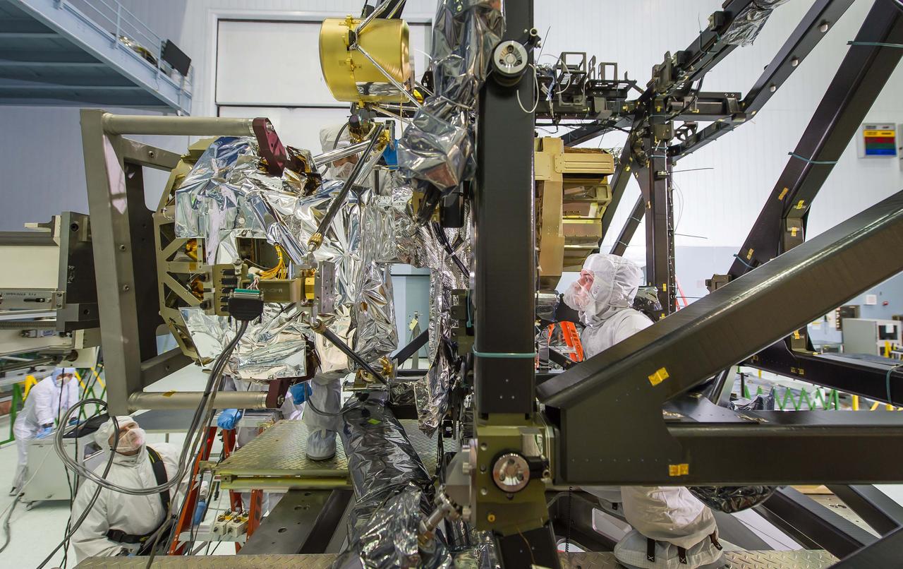
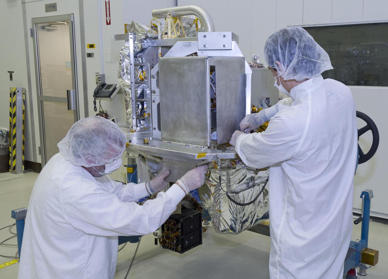
Engineers Tom Huber (behind MIRI) and Mick Wilks (inside black ISIM Structure) check that MIRI is integrated precisely. The engineers have to make sure that MIRI, the only instrument on the Webb telescope that 'sees' mid-infrared light, is precisely positioned so that it and the other instruments can glimpse the formation of galaxies and see deeper into the universe than ever before. Photo Credit: NASA/Chris Gunn; Text Credit: NASA/Laura Betz ---- Engineers worked meticulously to implant the James Webb Space Telescope's Mid-Infrared Instrument into the ISIM, or Integrated Science Instrument Module, in the cleanroom at NASA's Goddard Space Flight Center in Greenbelt, Md. As the successor to NASA's Hubble Space Telescope, the Webb telescope will be the most powerful space telescope ever built. It will observe the most distant objects in the universe, provide images of the first galaxies formed and see unexplored planets around distant stars. For more information, visit: <a href="http://www.jwst.nasa.gov" rel="nofollow">www.jwst.nasa.gov</a> <b><a href="http://www.nasa.gov/audience/formedia/features/MP_Photo_Guidelines.html" rel="nofollow">NASA image use policy.</a></b> <b><a href="http://www.nasa.gov/centers/goddard/home/index.html" rel="nofollow">NASA Goddard Space Flight Center</a></b> enables NASA’s mission through four scientific endeavors: Earth Science, Heliophysics, Solar System Exploration, and Astrophysics. Goddard plays a leading role in NASA’s accomplishments by contributing compelling scientific knowledge to advance the Agency’s mission. <b>Follow us on <a href="http://twitter.com/NASA_GoddardPix" rel="nofollow">Twitter</a></b> <b>Like us on <a href="http://www.facebook.com/pages/Greenbelt-MD/NASA-Goddard/395013845897?ref=tsd" rel="nofollow">Facebook</a></b> <b>Find us on <a href="http://instagram.com/nasagoddard?vm=grid" rel="nofollow">Instagram</a></b>
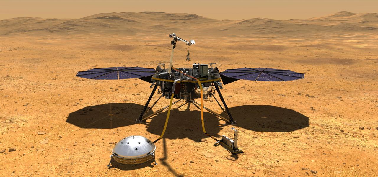
This artist's concept depicts NASA's InSight lander after it has deployed its instruments on the Martian surface. https://photojournal.jpl.nasa.gov/catalog/PIA22743

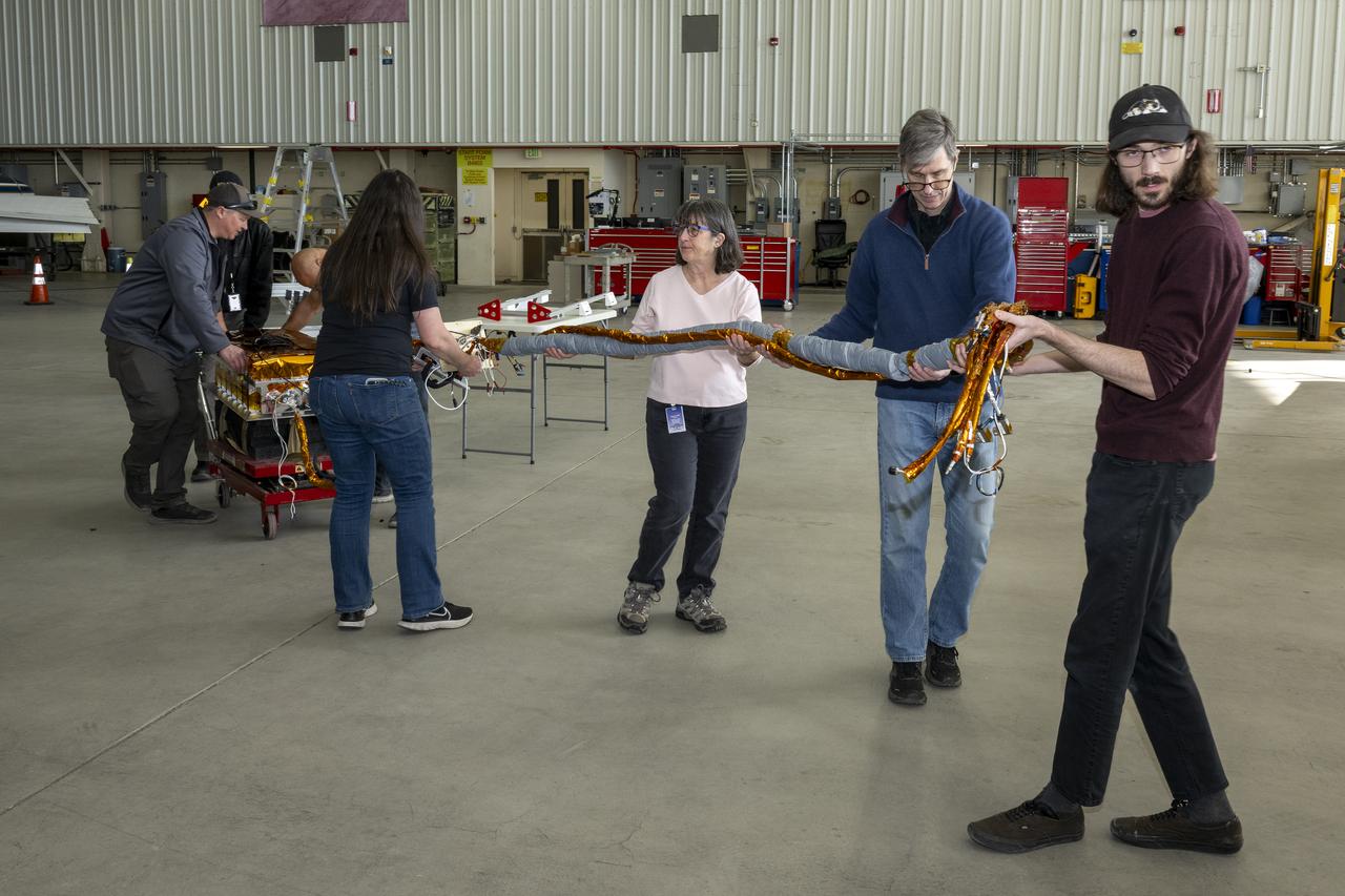
The High Altitude Lidar Observatory (HALO) instrument head, which houses the lidar instrument, is installed onto the DC-8 airborne science laboratory at NASA Armstrong Flight Research Center in Edwards, California. The gold and blue casing holds the laser, optics, detectors, and electronics, which are at the heart of the lidar.
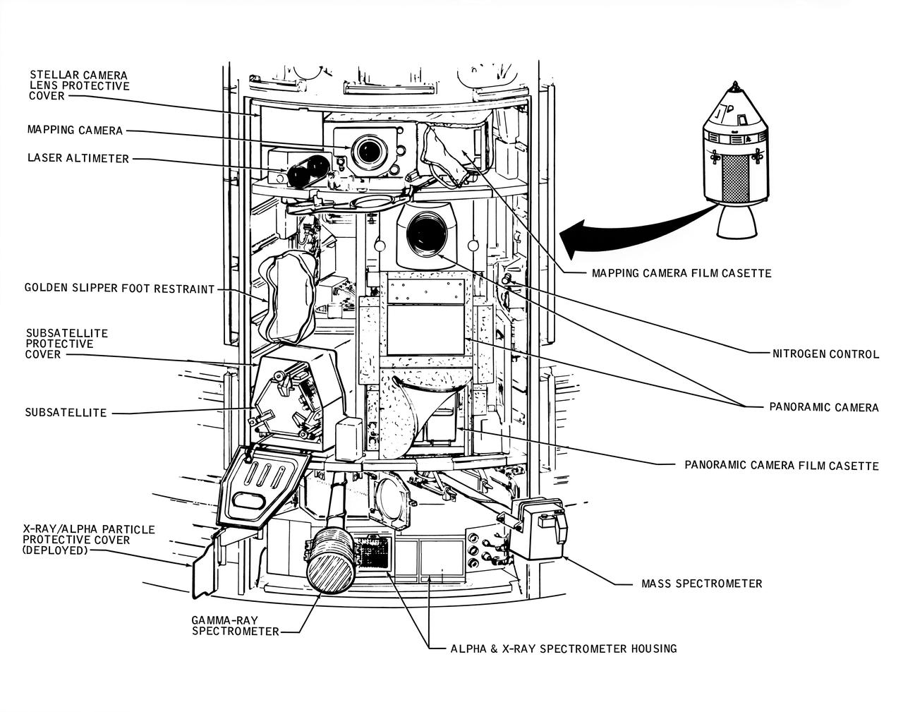
A line drawing illustrating the layout of the Scietific Instrument Module (SIM) of the Apollo 16 Service Module. Shown here is the location in the SIM bay of the equipment for each orbital experiment. Arrows point to various components of the SIM bay. The sensors for the gamma ray spectrometer and the mas spectrometer both extend outward on a boom about 25 feet when the instruments are in use. The subsatellite is launched while the Service Module is in orbit around the moon. The film cassettes must be retrieved prior to Command Module/Service Module separation.

Engineers at NASA's Jet Propulsion Laboratory – from left, Brandon Creager, Juan Gloria, Joshua Nachtigal, and Sonny Gutierrez – are shown assembling the electronics palette for the Coronagraph Instrument on NASA's Roman Space Telescope in December 2022. One of two main sections of the instrument, this layer houses the instrument electronics that receive instructions from the Roman spacecraft and send back the Coronagraph Instrument's scientific data. The electronics also control the mechanical components on the optical bench and the instrument heaters. https://photojournal.jpl.nasa.gov/catalog/PIA25435
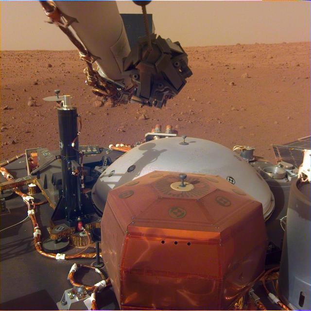
This image from InSight's robotic-arm mounted Instrument Deployment Camera shows the instruments on the spacecraft's deck, with the Martian surface of Elysium Planitia in the background. The color-calibrated picture was acquired on Dec. 4, 2018 (Sol 8). In the foreground, a copper-colored hexagonal cover protects the Seismic Experiment for Interior Structure instrument (SEIS), a seismometer that will measure marsquakes. The gray dome behind SEIS is the wind and thermal shield, which will be placed over SEIS. To the left is a black cylindrical instrument, the Heat Flow and Physical Properties Probe (HP3). HP3 will drill up to 16 feet (5 meters) below the Martian surface, measuring heat released from the interior of the planet. Above the deck is InSight's robotic arm, with the stowed grapple directly facing the camera. To the right can be seen a small portion of one of the two solar panels that help power InSight and part of the UHF communication antenna. https://photojournal.jpl.nasa.gov/catalog/PIA22871

Engineers are checking to make sure that MIRI is precisely positioned with the ISIM as it slides into position. They have to make sure it's installed exactly where it needs to be within the width of a thin human hair. Visible is MIRI's pickoff mirror, which is the protrusion on the right side of the instrument that looks like a periscope on its side. This is where MIRI grabs light coming from the telescope optics. Also visible is the silver-colored base of MIRI's cryocooled shield, already installed on the ISIM structure and with a hole in it for MIRI's pickoff mirror. MIRI itself has special silver-colored blanketing around it as insulation to keep it at its proper cryogenic temperature during operation. Photo Credit: NASA/Chris Gunn; Text Credit: NASA/Laura Betz ---- Engineers worked meticulously to implant the James Webb Space Telescope's Mid-Infrared Instrument into the ISIM, or Integrated Science Instrument Module, in the cleanroom at NASA's Goddard Space Flight Center in Greenbelt, Md. As the successor to NASA's Hubble Space Telescope, the Webb telescope will be the most powerful space telescope ever built. It will observe the most distant objects in the universe, provide images of the first galaxies formed and see unexplored planets around distant stars. For more information, visit: <a href="http://www.jwst.nasa.gov" rel="nofollow">www.jwst.nasa.gov</a> <b><a href="http://www.nasa.gov/audience/formedia/features/MP_Photo_Guidelines.html" rel="nofollow">NASA image use policy.</a></b> <b><a href="http://www.nasa.gov/centers/goddard/home/index.html" rel="nofollow">NASA Goddard Space Flight Center</a></b> enables NASA’s mission through four scientific endeavors: Earth Science, Heliophysics, Solar System Exploration, and Astrophysics. Goddard plays a leading role in NASA’s accomplishments by contributing compelling scientific knowledge to advance the Agency’s mission. <b>Follow us on <a href="http://twitter.com/NASA_GoddardPix" rel="nofollow">Twitter</a></b> <b>Like us on <a href="http://www.facebook.com/pages/Greenbelt-MD/NASA-Goddard/395013845897?ref=tsd" rel="nofollow">Facebook</a></b> <b>Find us on <a href="http://instagram.com/nasagoddard?vm=grid" rel="nofollow">Instagram</a></b>
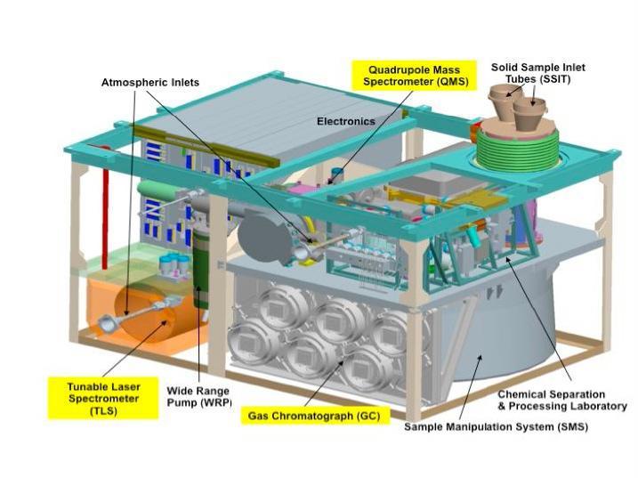
This schematic illustration for NASA Mars Science Laboratory Sample Analysis at Mars SAM instrument shows major components of the microwave-oven-size instrument, which will examine samples of Martian rocks, soil and atmosphere.
This graphic shows the NASA Voyager 1 spacecraft and the location of its low-energy charged particle instrument. A labeled close-up of the low-energy charged particle instrument appears as the inset image.
NASA Sample Analysis at Mars SAM instrument, largest of the 10 science instruments for NASA Mars Science Laboratory mission, will examine samples of Martian rocks, soil and atmosphere for information about chemicals that are important to life.
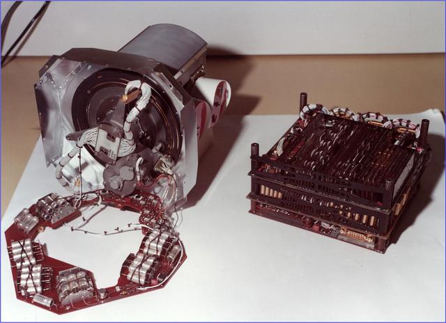
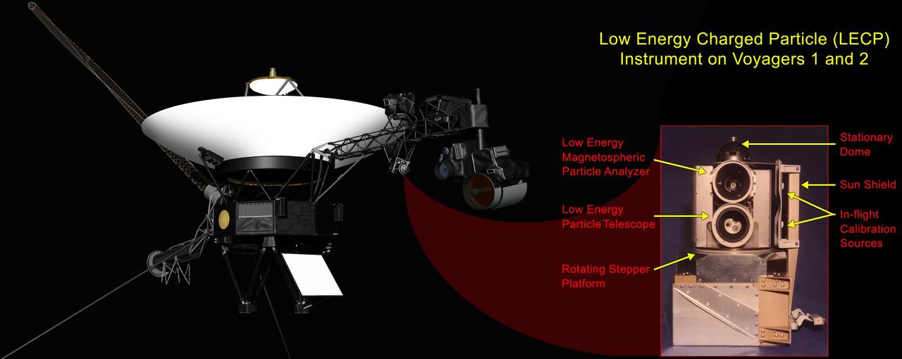
This image shows the low-energy charged particle instrument before it was installed on one of NASA Voyager spacecraft in 1977. The instrument includes a stepper motor that turns the platform on which the sensors are mounted.
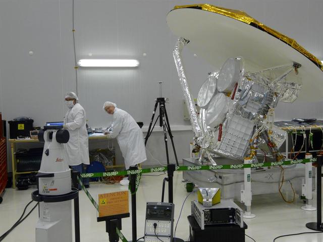
NASA Aquarius instrument power interfaces are tested prior to connection with the SAC-D service platform at the INVAP facility in Bariloche, Argentina.
Engineers and technicians at NASA’s Kennedy Space Center in Florida work with instruments for Mass Spectrometer observing lunar operations (MSolo) inside the Space Station Processing on Sept. 25, 2020. MSolo is a commercial off-the-shelf mass spectrometer modified to work in space and it will help analyze the chemical makeup of landing sites on the Moon, as well as study water on the lunar surface. This work is preparing MSolo hardware for a robotic mission as part of the Commercial Lunar Payload Services (CLPS) launching to exploring Lacus Mortis, a large crater on the near side of the Moon in 2021. A future mission will send a mobile robot named the Volatiles Investigating Polar Exploration Rover (VIPER) to the Moon to prospect for water. VIPER will have several instruments that will allow it to detect and sample water including MSolo, the Neutron Spectrometer System, the Near Infrared Volatiles Spectrometer System and The Regolith and Ice Drill for Exploring New Terrain (TRIDENT).
Instruments for the Mass Spectrometer observing lunar operations (MSolo) are in view inside the Space Station Processing Facility at NASA’s Kennedy Space Center in Florida on Sept. 25, 2020. MSolo is a commercial off-the-shelf mass spectrometer modified to work in space and it will help analyze the chemical makeup of landing sites on the Moon, as well as study water on the lunar surface. This work is preparing MSolo hardware for a robotic mission as part of the Commercial Lunar Payload Services (CLPS) launching to exploring Lacus Mortis, a large crater on the near side of the Moon in 2021. A future mission will send a mobile robot named the Volatiles Investigating Polar Exploration Rover (VIPER) to the Moon to prospect for water. VIPER will have several instruments that will allow it to detect and sample water including MSolo, the Neutron Spectrometer System, the Near Infrared Volatiles Spectrometer System and The Regolith and Ice Drill for Exploring New Terrain (TRIDENT).
Engineers and technicians at NASA’s Kennedy Space Center in Florida work with instruments for Mass Spectrometer observing lunar operations (MSolo) inside the Space Station Processing on Sept. 25, 2020. MSolo is a commercial off-the-shelf mass spectrometer modified to work in space and it will help analyze the chemical makeup of landing sites on the Moon, as well as study water on the lunar surface. This work is preparing MSolo hardware for a robotic mission as part of the Commercial Lunar Payload Services (CLPS) launching to exploring Lacus Mortis, a large crater on the near side of the Moon in 2021. A future mission will send a mobile robot named the Volatiles Investigating Polar Exploration Rover (VIPER) to the Moon to prospect for water. VIPER will have several instruments that will allow it to detect and sample water including MSolo, the Neutron Spectrometer System, the Near Infrared Volatiles Spectrometer System and The Regolith and Ice Drill for Exploring New Terrain (TRIDENT).
Engineers and technicians at NASA’s Kennedy Space Center in Florida work with instruments for Mass Spectrometer observing lunar operations (MSolo) inside the Space Station Processing on Sept. 25, 2020. MSolo is a commercial off-the-shelf mass spectrometer modified to work in space and it will help analyze the chemical makeup of landing sites on the Moon, as well as study water on the lunar surface. This work is preparing MSolo hardware for a robotic mission as part of the Commercial Lunar Payload Services (CLPS) launching to exploring Lacus Mortis, a large crater on the near side of the Moon in 2021. A future mission will send a mobile robot named the Volatiles Investigating Polar Exploration Rover (VIPER) to the Moon to prospect for water. VIPER will have several instruments that will allow it to detect and sample water including MSolo, the Neutron Spectrometer System, the Near Infrared Volatiles Spectrometer System and The Regolith and Ice Drill for Exploring New Terrain (TRIDENT).
Engineers and technicians at NASA’s Kennedy Space Center in Florida work with instruments for Mass Spectrometer observing lunar operations (MSolo) inside the Space Station Processing on Sept. 25, 2020. MSolo is a commercial off-the-shelf mass spectrometer modified to work in space and it will help analyze the chemical makeup of landing sites on the Moon, as well as study water on the lunar surface. This work is preparing MSolo hardware for a robotic mission as part of the Commercial Lunar Payload Services (CLPS) launching to exploring Lacus Mortis, a large crater on the near side of the Moon in 2021. A future mission will send a mobile robot named the Volatiles Investigating Polar Exploration Rover (VIPER) to the Moon to prospect for water. VIPER will have several instruments that will allow it to detect and sample water including MSolo, the Neutron Spectrometer System, the Near Infrared Volatiles Spectrometer System and The Regolith and Ice Drill for Exploring New Terrain (TRIDENT).
Engineers and technicians at NASA’s Kennedy Space Center in Florida work with instruments for Mass Spectrometer observing lunar operations (MSolo) inside the Space Station Processing on Sept. 25, 2020. MSolo is a commercial off-the-shelf mass spectrometer modified to work in space and it will help analyze the chemical makeup of landing sites on the Moon, as well as study water on the lunar surface. This work is preparing MSolo hardware for a robotic mission as part of the Commercial Lunar Payload Services (CLPS) launching to exploring Lacus Mortis, a large crater on the near side of the Moon in 2021. A future mission will send a mobile robot named the Volatiles Investigating Polar Exploration Rover (VIPER) to the Moon to prospect for water. VIPER will have several instruments that will allow it to detect and sample water including MSolo, the Neutron Spectrometer System, the Near Infrared Volatiles Spectrometer System and The Regolith and Ice Drill for Exploring New Terrain (TRIDENT).
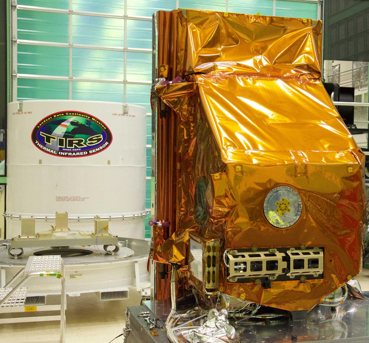
The TIRS instrument in the foreground with its shipping container waits in the background. The copper-color of TIRS is due to the gold-colored foil that coats the Multi-Layer Insulation blankets. The Thermal Infrared Sensor (TIRS) will fly on the next Landsat satellite, the Landsat Data Continuity Mission (LDCM). TIRS was built on an accelerated schedule at NASA's Goddard Space Flight Center, Greenbelt, Md. and will now be integrated into the LDCM spacecraft at Orbital Science Corp. in Gilbert, Ariz. The Landsat Program is a series of Earth observing satellite missions jointly managed by NASA and the U.S. Geological Survey. Landsat satellites have been consistently gathering data about our planet since 1972. They continue to improve and expand this unparalleled record of Earth's changing landscapes for the benefit of all. For more information on Landsat, visit: <a href="http://www.nasa.gov/landsat" rel="nofollow">www.nasa.gov/landsat</a> Credit: NASA/GSFC/Rebecca Roth <b><a href="http://www.nasa.gov/audience/formedia/features/MP_Photo_Guidelines.html" rel="nofollow">NASA image use policy.</a></b> <b><a href="http://www.nasa.gov/centers/goddard/home/index.html" rel="nofollow">NASA Goddard Space Flight Center</a></b> enables NASA’s mission through four scientific endeavors: Earth Science, Heliophysics, Solar System Exploration, and Astrophysics. Goddard plays a leading role in NASA’s accomplishments by contributing compelling scientific knowledge to advance the Agency’s mission. <b>Follow us on <a href="http://twitter.com/NASA_GoddardPix" rel="nofollow">Twitter</a></b> <b>Like us on <a href="http://www.facebook.com/pages/Greenbelt-MD/NASA-Goddard/395013845897?ref=tsd" rel="nofollow">Facebook</a></b> <b>Find us on <a href="http://instagrid.me/nasagoddard/?vm=grid" rel="nofollow">Instagram</a></b>
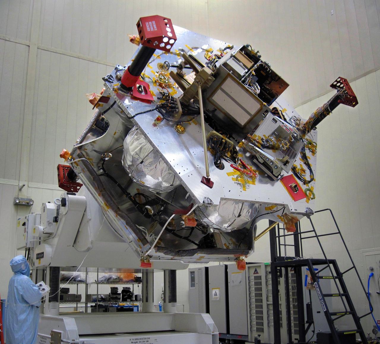
Once the radiation vault was installed on top of the propulsion module, NASA Juno spacecraft was lifted onto a large rotation fixture. The fixture allows the spacecraft to be turned for convenient access for integrating and testing instruments.

Three of NASA contributions to the ESA Rosetta mission are pictured here: an ultraviolet spectrometer called Alice top, the Ion and Electron Sensor IES bottom left, and the Microwave Instrument for Rosetta Orbiter MIRO bottom right.
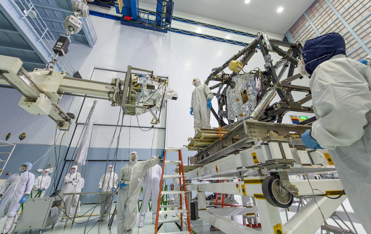
The MIRI itself weighs 181 pounds (82 kg) and is being held by a special balance beam (on the left of the photo), which is being maneuvered using a precision overhead crane by the engineer at the base of the ladder. Photo Credit: NASA/Chris Gunn; Text Credit: NASA/Laura Betz ---- Engineers worked meticulously to implant the James Webb Space Telescope's Mid-Infrared Instrument into the ISIM, or Integrated Science Instrument Module, in the cleanroom at NASA's Goddard Space Flight Center in Greenbelt, Md. As the successor to NASA's Hubble Space Telescope, the Webb telescope will be the most powerful space telescope ever built. It will observe the most distant objects in the universe, provide images of the first galaxies formed and see unexplored planets around distant stars. For more information, visit: <a href="http://www.jwst.nasa.gov" rel="nofollow">www.jwst.nasa.gov</a> <b><a href="http://www.nasa.gov/audience/formedia/features/MP_Photo_Guidelines.html" rel="nofollow">NASA image use policy.</a></b> <b><a href="http://www.nasa.gov/centers/goddard/home/index.html" rel="nofollow">NASA Goddard Space Flight Center</a></b> enables NASA’s mission through four scientific endeavors: Earth Science, Heliophysics, Solar System Exploration, and Astrophysics. Goddard plays a leading role in NASA’s accomplishments by contributing compelling scientific knowledge to advance the Agency’s mission. <b>Follow us on <a href="http://twitter.com/NASA_GoddardPix" rel="nofollow">Twitter</a></b> <b>Like us on <a href="http://www.facebook.com/pages/Greenbelt-MD/NASA-Goddard/395013845897?ref=tsd" rel="nofollow">Facebook</a></b> <b>Find us on <a href="http://instagram.com/nasagoddard?vm=grid" rel="nofollow">Instagram</a></b>
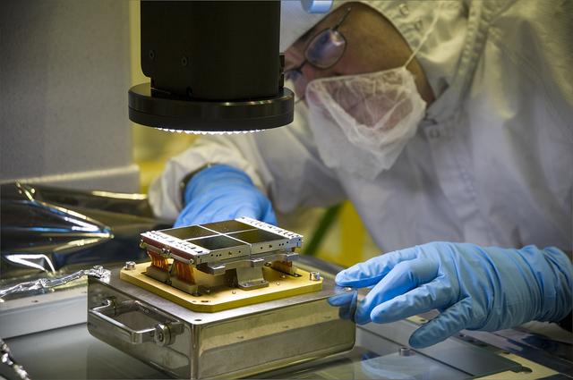
Dressed in a cleanroom suit to prevent contamination, Optics Technician Jeff Gum aligns a replacement Focal Plane Assembly (FPA) with a powerful three-dimensional microscope at NASA's Goddard Space Flight Center in Greenbelt, Md. This FPA will be installed on the Near Infrared Camera (NIRCam) instrument, which has unique components that are individually tailored to see in a particular infrared wavelength range. By using the microscope, Gum ensures the FPA detectors are characterized and ready for installation onto NIRCam, the James Webb Space Telescope's primary imager that will see the light from the earliest stars and galaxies that formed in the universe. Credit: NASA/Goddard/Chris Gunn <b><a href="http://www.nasa.gov/audience/formedia/features/MP_Photo_Guidelines.html" rel="nofollow">NASA image use policy.</a></b> <b><a href="http://www.nasa.gov/centers/goddard/home/index.html" rel="nofollow">NASA Goddard Space Flight Center</a></b> enables NASA’s mission through four scientific endeavors: Earth Science, Heliophysics, Solar System Exploration, and Astrophysics. Goddard plays a leading role in NASA’s accomplishments by contributing compelling scientific knowledge to advance the Agency’s mission. <b>Follow us on <a href="http://twitter.com/NASAGoddardPix" rel="nofollow">Twitter</a></b> <b>Like us on <a href="http://www.facebook.com/pages/Greenbelt-MD/NASA-Goddard/395013845897?ref=tsd" rel="nofollow">Facebook</a></b> <b>Find us on <a href="http://instagram.com/nasagoddard?vm=grid" rel="nofollow">Instagram</a></b>
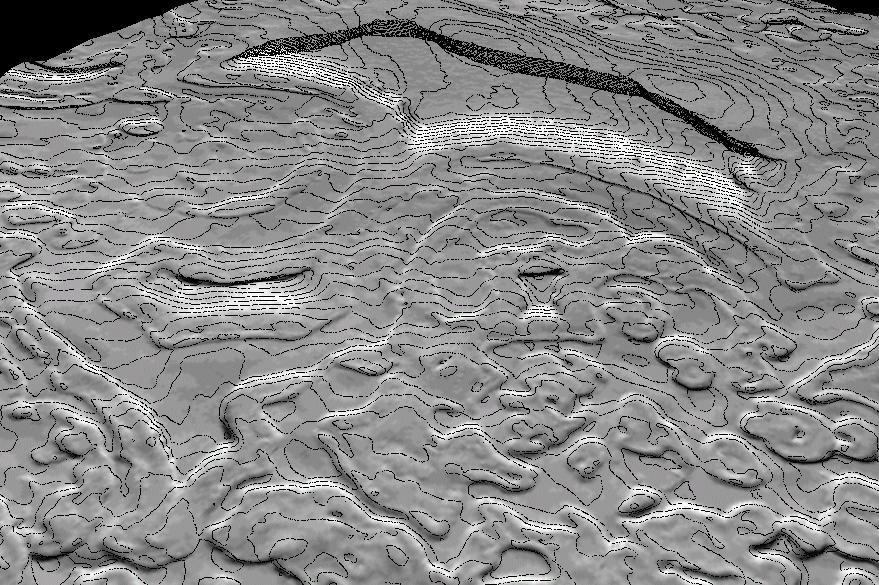
New Views of Mars from the Thermal Emission Spectrometer Instrument
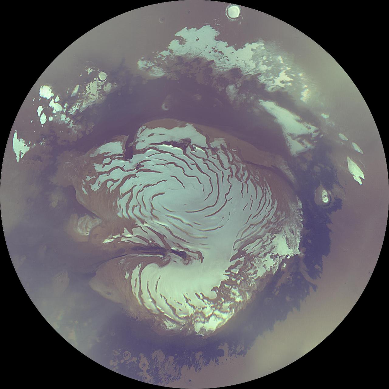
Mars Polar Cap During Transition Phase Instrument Checkout
Derived Topographic Model from Mars Global Surveyor Instruments
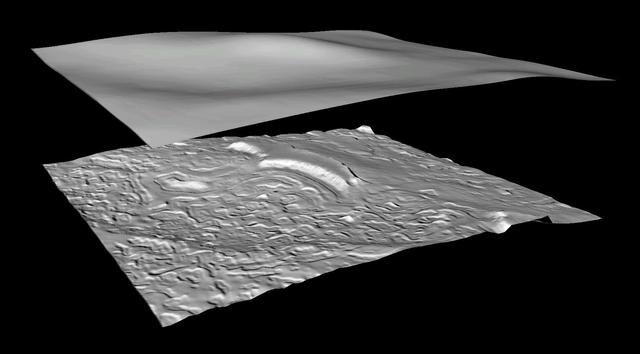
Derived Topographic Model from Mars Global Surveyor Instruments
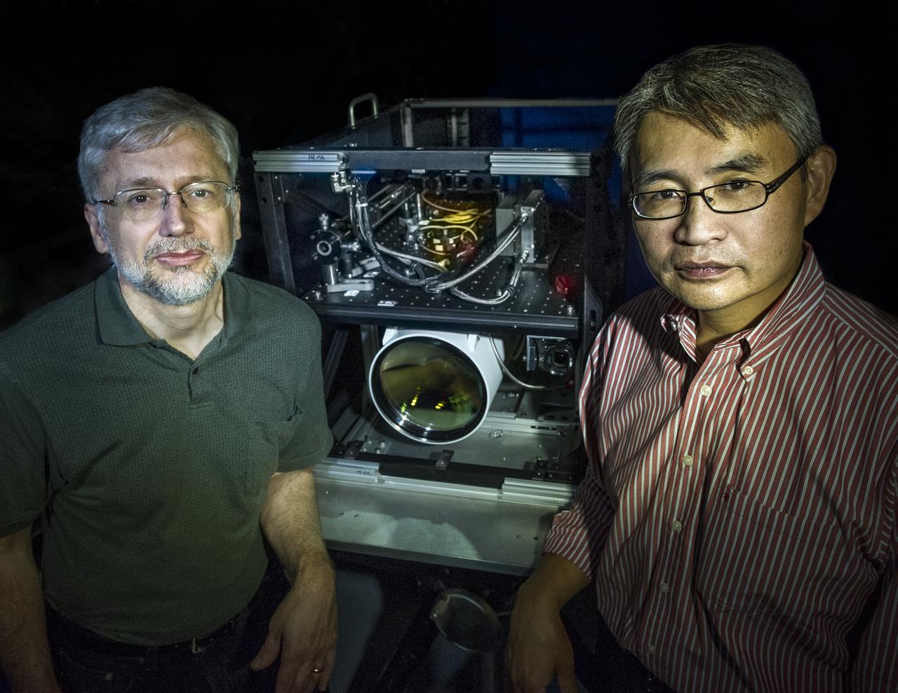
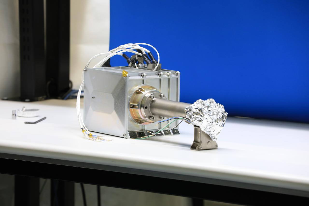
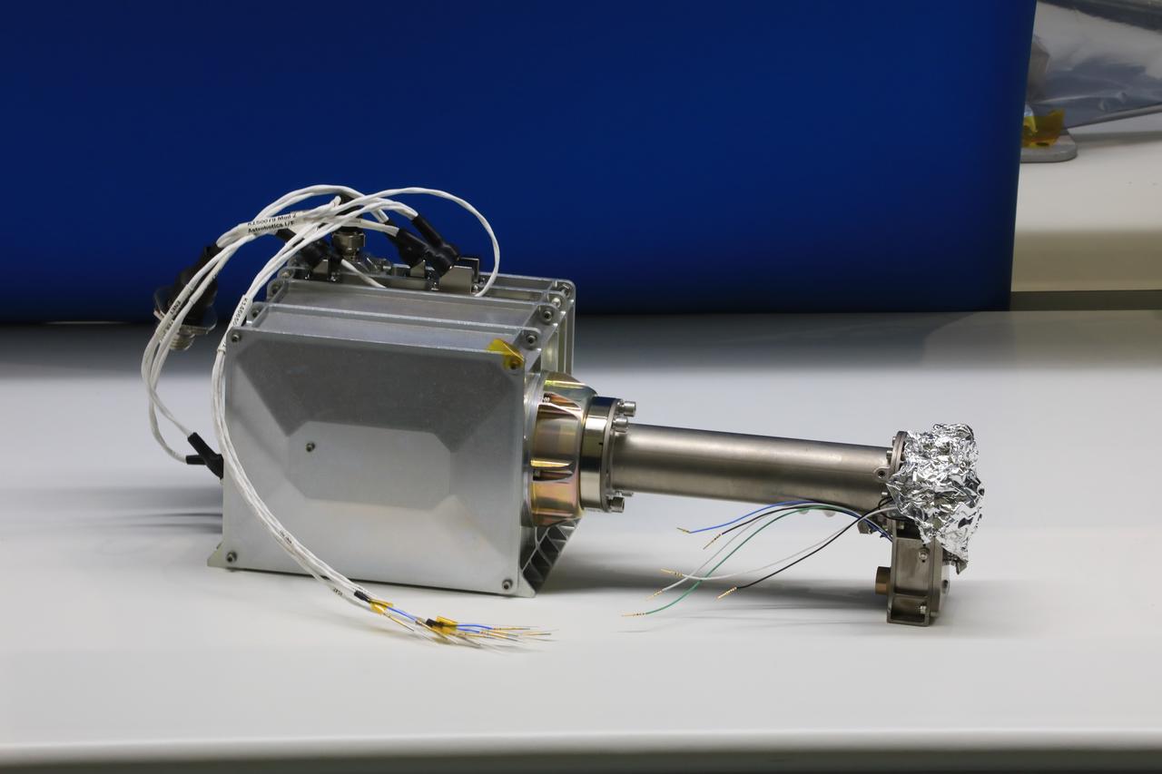
Goddard scientist David Harding and Goddard technologist Tony Yu are developing a lidar system that could meet an ambitious requirement of the proposed LIST mission. ---------- In 2007, the National Research Council threw down a challenge: Design a space-based laser altimeter that could measure the height of Earth's surface everywhere to within a mere 10 centimeters — all at 5-meter resolution. To this day, some believe it can't be done. Goddard scientist Dave Harding begs to differ. He and his team have embraced the challenge and are developing a laser altimeter that could provide the data from a berth onboard the NRC-proposed Lidar Surface Topography, or LIST, mission. It would generate highly detailed maps of topography and vegetation that scientists could use to forecast and respond to natural hazards and study carbon storage in forests. Read more: <a href="http://1.usa.gov/17N3Bql" rel="nofollow">1.usa.gov/17N3Bql</a> <b><a href="http://www.nasa.gov/audience/formedia/features/MP_Photo_Guidelines.html" rel="nofollow">NASA image use policy.</a></b> <b><a href="http://www.nasa.gov/centers/goddard/home/index.html" rel="nofollow">NASA Goddard Space Flight Center</a></b> enables NASA’s mission through four scientific endeavors: Earth Science, Heliophysics, Solar System Exploration, and Astrophysics. Goddard plays a leading role in NASA’s accomplishments by contributing compelling scientific knowledge to advance the Agency’s mission. <b>Follow us on <a href="http://twitter.com/NASA_GoddardPix" rel="nofollow">Twitter</a></b> <b>Like us on <a href="http://www.facebook.com/pages/Greenbelt-MD/NASA-Goddard/395013845897?ref=tsd" rel="nofollow">Facebook</a></b> <b>Find us on <a href="http://instagram.com/nasagoddard?vm=grid" rel="nofollow">Instagram</a></b> Credit: Bill Hrybck/NASA
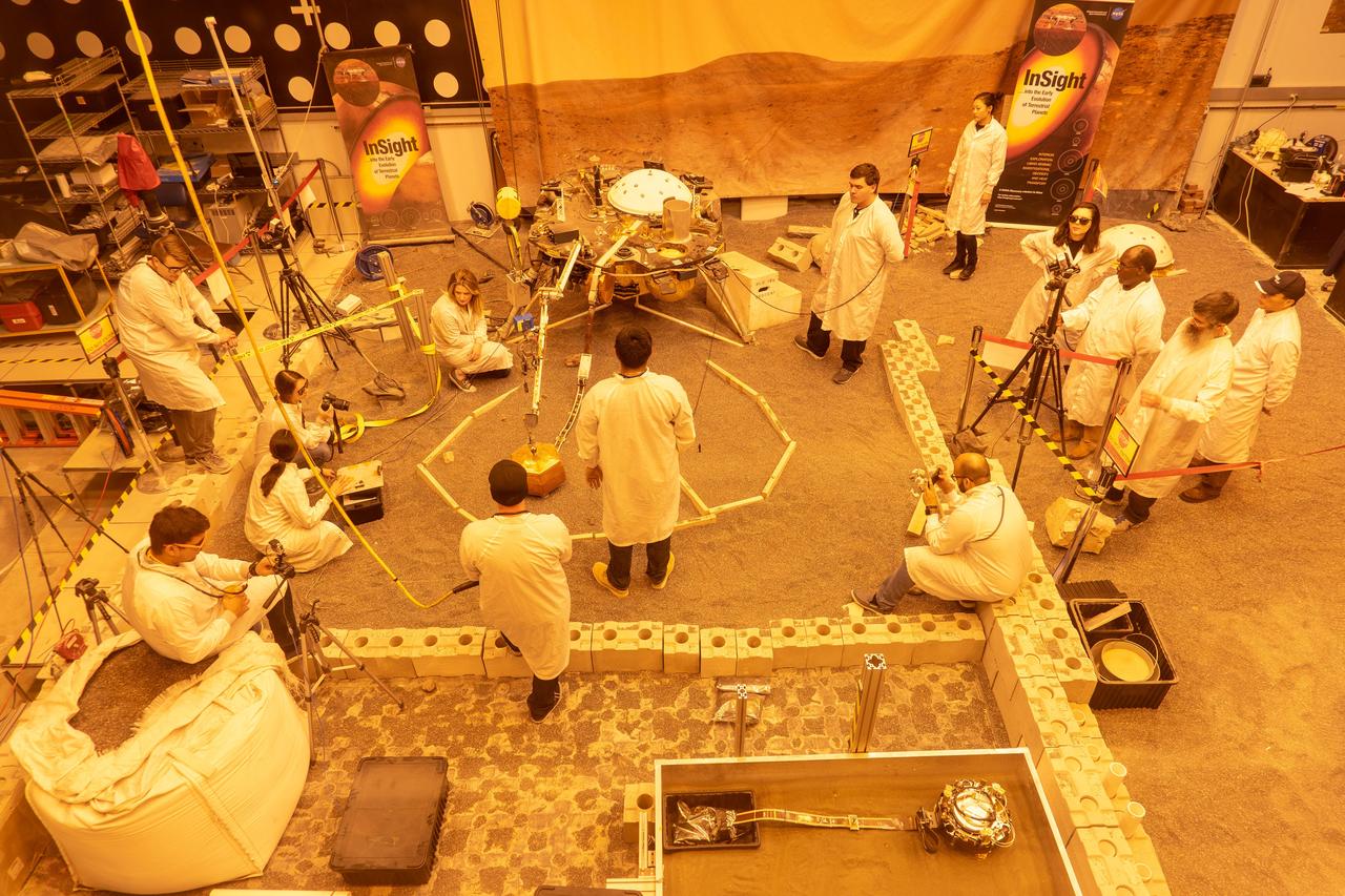
Engineers practice deploying InSight's instruments in a lab at NASA's Jet Propulsion Laboratory in Pasadena, California. Several of them are wearing sunglasses to block the bright yellow lights in the test space, which mimic sunlight as it appears on Mars. The yellow lights are used to test cameras which are the same as those used by InSight on Mars. The entire lab space in the center of the image has been sculpted to mimic the terrain in front of the lander on Mars, creating more reliable test conditions. The area in the center of the image is the "workspace" where the lander's instruments can be set down; wood blocks have been laid down to mark the perimeter of these areas. Rocks have been chosen to match the size, shape and location of those in front of InSight on Mars. In the center of the image is a model of the lander's copper-colored seismometer; at the bottom-right is a second model of the seismometer used for a different kind of testing. In the lower left corner of the image is a bag of crushed granite, which is used in this lab to simulate Martian sand. https://photojournal.jpl.nasa.gov/catalog/PIA22744
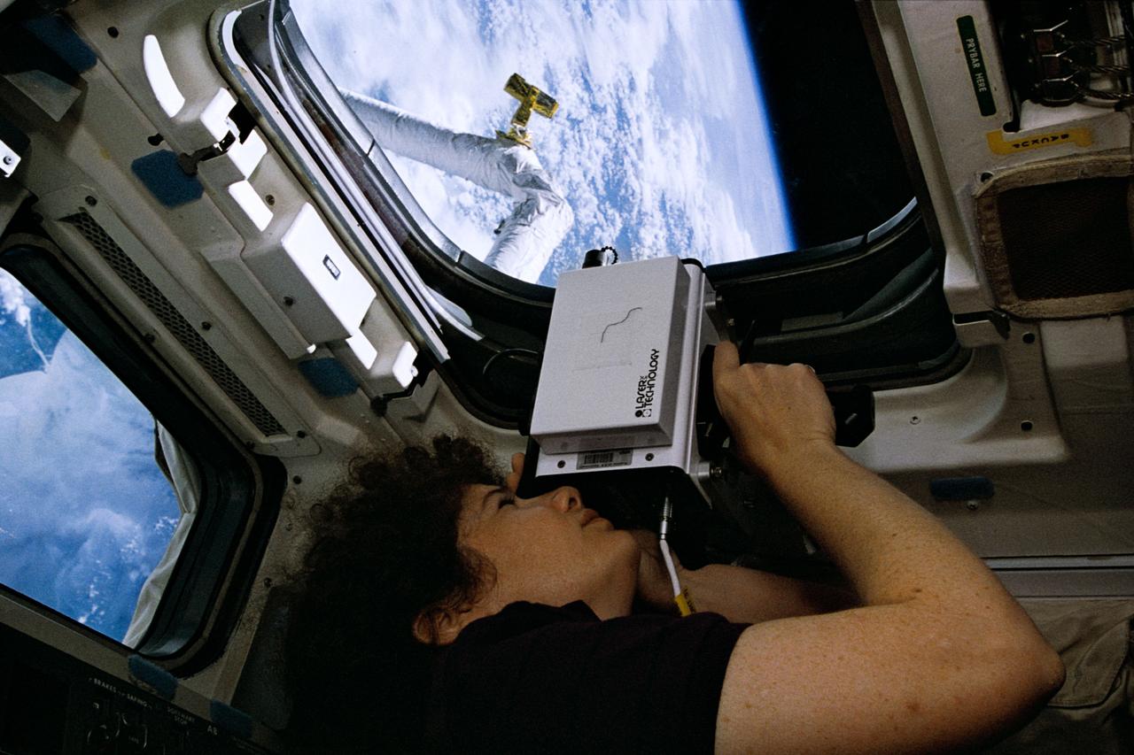
STS064-33-003 (9-20 Sept. 1994) --- Astronaut Susan J. Helms, STS-64 mission specialist, uses a laser instrument during operations with the Shuttle Pointed Autonomous Research Tool for Astronomy 201 (SPARTAN 201). Helms, who spent many mission hours at the controls of the Remote Manipulator System (RMS), joined five other NASA astronauts for almost 11 days in Earth orbit aboard the space shuttle Discovery. Photo credit: NASA or National Aeronautics and Space Administration
The two main parts of the ChemCam laser instrument for NASA Mars Science Laboratory mission are shown in this combined image.

This image of the Crab Pulsar was taken with CHIMERA, an instrument at the Palomar Observatory, which is operated by the California Institute of Technology.
Technicians prep NASA OCO-2 instrument for shipping at Jet Propulsion Lab in Pasadena, Ca.
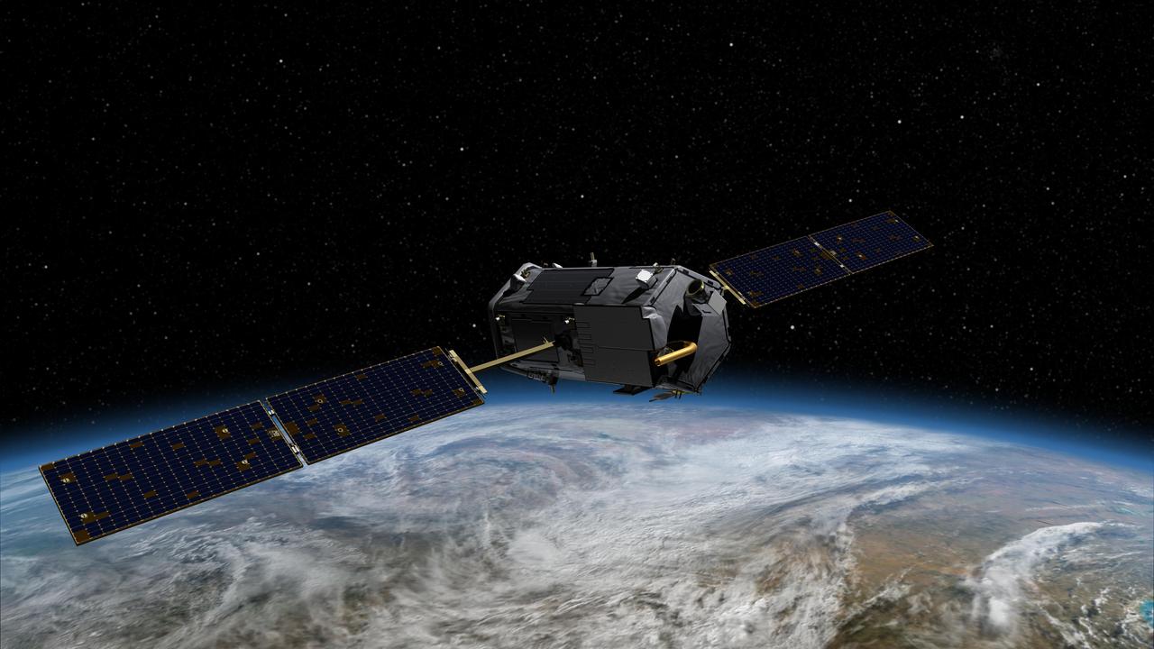
Technicians prep NASA OCO-2 instrument for shipping at Jet Propulsion Lab in Pasadena, Ca. Animation available in More Details.
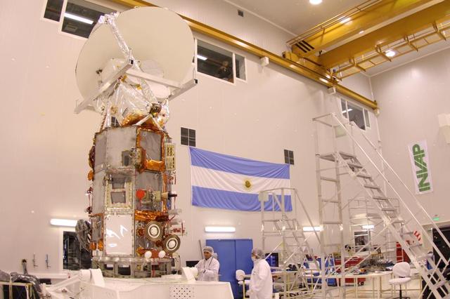
NASA Aquarius instrument on SAC-D sevice platform in INVAP high bay facility for mechanical integration activities.
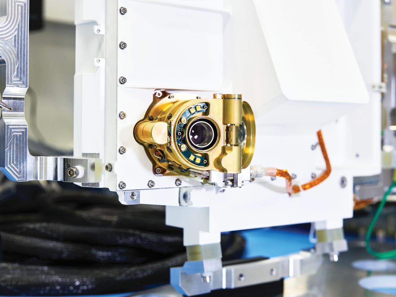
A close-up view of an engineering model of SHERLOC (Scanning Habitable Environments with Raman & Luminescence for Organics & Chemicals), one the instruments aboard NASA's Perseverance Mars rover. Located on the end of the rover's robotic arm, this instrument features an auto-focusing camera (pictured) that shoots black-and-white images used by SHERLOC's color camera, called WATSON (Wide Angle Topographic Sensor for Operations and eNgineering), to zero in on rock textures. SHERLOC also has a laser, which aims for the dead center of rock surfaces depicted in WATSON's images. The laser uses a technique called Raman spectroscopy to detect minerals in microscopic rock features; that data is then superimposed on WATSON's images. These mineral maps help scientists determine which rock samples Perseverance should drill so that they can be sealed in metal tubes and left on the Martian surface for a future mission to return to Earth. https://photojournal.jpl.nasa.gov/catalog/PIA23894
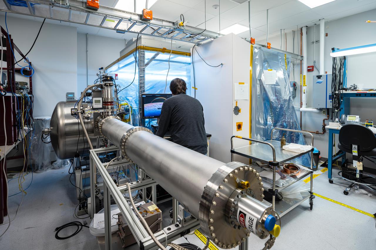
Included in the payload of science instruments for NASA's Europa Clipper is the Plasma Instrument for Magnetic Sounding (PIMS). Scientists will use PIMS to study the characteristics of plasma around Europa to better understand the moon's ice-shell thickness, ocean depth, and ocean salinity. PIMS will have four sensors, called Faraday cups, to measure the electrical current produced by charged particles (or plasma) as they strike a detector plate inside each sensor. In this photo, the Plasma Instrument Calibration Chamber at the Johns Hopkins Applied Physics Laboratory (APL) in Laurel, Maryland, recreates the plasma environments that PIMS and other instruments will encounter in space. The equipment in this lab simulates these environments with ion beams that reproduce plasma energy ranges found at Jupiter and Europa. Once PIMS is fully assembled in the clean room attached to the chamber, the team will direct these ion and electron beams into the Faraday cup sensors for calibration. This will be used specifically to simulate the plasma in Europa's ionosphere and Jupiter's magnetosphere, which PIMS will later measure directly. With an internal global ocean twice the size of Earth's oceans combined, Europa may have the potential to harbor life. NASA's Europa Clipper spacecraft will swoop around Jupiter on an elliptical path, dipping close to the moon on each flyby to collect data. Understanding Europa's habitability will help scientists better understand how life developed on Earth and the potential for finding life beyond our planet. https://photojournal.jpl.nasa.gov/catalog/PIA24330
The airborne Lunar Spectral Irradiance (air-LUSI) instrument is moved across the hangar floor by robotic engineer Alexander McCafferty-Leroux ,from right to left, co-investigator Dr. John Woodward, NIST astronomer Dr. Susana Deustua, air-LUSI chief system engineer Dr. Kathleen “Kat” Scanlon, and members of the ER-2 ground crew at NASA’s Armstrong Flight Research Center in Edwards, California, in March 2025.
Engineers and technicians at NASA’s Kennedy Space Center in Florida are preparing the Mass Spectrometer observing lunar operations (MSolo) for launch inside the Space Station Processing Facility at NASA’s Kennedy Space Center in Florida on Sept. 25, 2020. MSolo is a commercial off-the-shelf mass spectrometer modified to work in space and it will help analyze the chemical makeup of landing sites on the Moon, as well as study water on the lunar surface. MSolo hardware is a payload for a robotic mission to the Moon as part of the Commercial Lunar Payload Services (CLPS) launching to exploring Lacus Mortis, a large crater on the near side of the Moon in 2021. A future mission will send a mobile robot named the Volatiles Investigating Polar Exploration Rover (VIPER) to the Moon to prospect for water. VIPER will have several instruments that will allow it to detect and sample water including MSolo, the Neutron Spectrometer System, the Near Infrared Volatiles Spectrometer System and The Regolith and Ice Drill for Exploring New Terrain (TRIDENT).
Engineers and technicians at NASA’s Kennedy Space Center in Florida are preparing the Mass Spectrometer observing lunar operations (MSolo) for launch inside the Space Station Processing Facility at NASA’s Kennedy Space Center in Florida on Sept. 25, 2020. MSolo is a commercial off-the-shelf mass spectrometer modified to work in space and it will help analyze the chemical makeup of landing sites on the Moon, as well as study water on the lunar surface. MSolo hardware is a payload for a robotic mission to the Moon as part of the Commercial Lunar Payload Services (CLPS) launching to exploring Lacus Mortis, a large crater on the near side of the Moon in 2021. A future mission will send a mobile robot named the Volatiles Investigating Polar Exploration Rover (VIPER) to the Moon to prospect for water. VIPER will have several instruments that will allow it to detect and sample water including MSolo, the Neutron Spectrometer System, the Near Infrared Volatiles Spectrometer System and The Regolith and Ice Drill for Exploring New Terrain (TRIDENT).
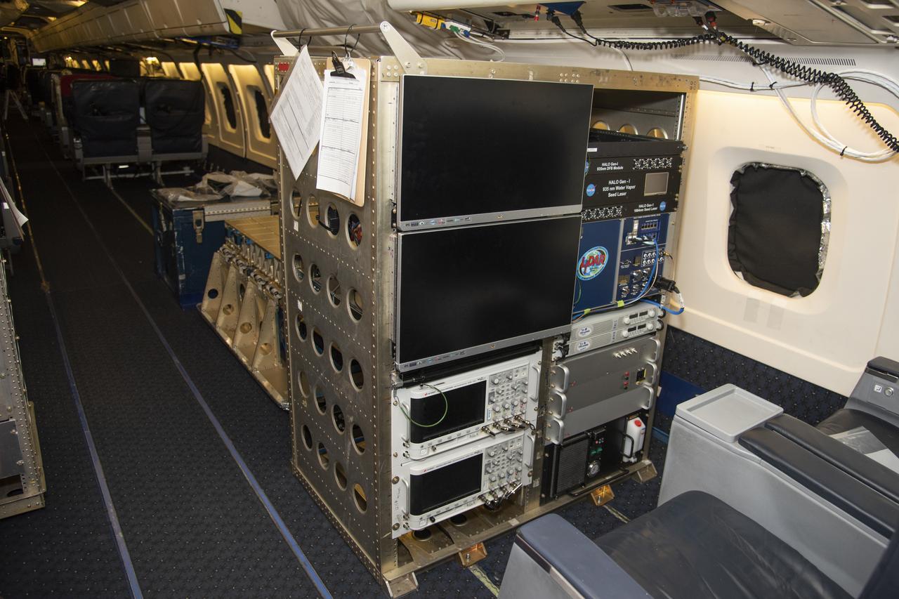
The High Altitude Lidar Observatory (HALO) system electronics and diagnostic tools are integrated onto the DC-8 airborne science laboratory at NASA Armstrong Flight Research Center in Edwards, California. The lidar system control electronics are on the right hand side of the rack. The large monitors on the left are used to display real-time images of water vapor and aerosol profiles, which are used by the science team to guide in-flight decisions and navigation. The compact HALO instrument head can be seen directly behind the electronics rack.
This frame from a series of images shows NASA Phoenix Mars Lander telltale instrument waving in the Martian wind. Documenting the telltale movement helps mission scientists and engineers determine what the wind is like on Mars.
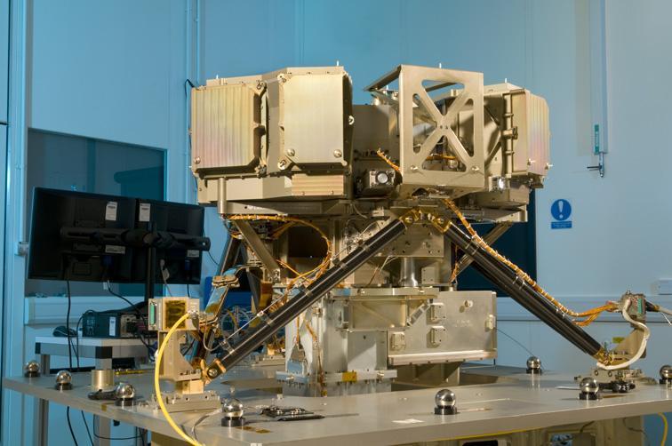
The Mid-Infrared Instrument, a component of NASA James Webb Space Telescope, underwent alignment testing at the Science and Technology Facilities Council Rutherford Appleton Laboratory Space in Oxfordshire, England.
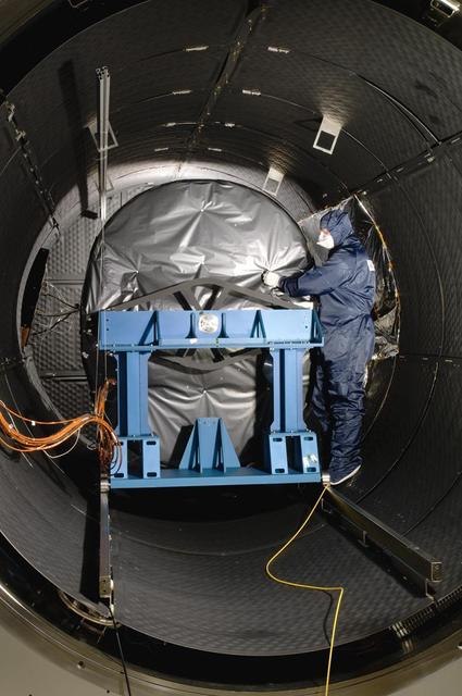
The Mid-Infrared Instrument, a component of NASA James Webb Space Telescope, underwent testing inside the thermal space test chamber at the Science and Technology Facilities Council Rutherford Appleton Laboratory Space in Oxfordshire, England.
Technicians install NASA's Tropospheric Emission Spectrometer (TES) instrument on NASA's Aura spacecraft prior to launch. Launched in July 2004 and designed to fly for two years, the TES mission is currently in an extended operations phase. Mission managers at NASA's Jet Propulsion Laboratory, Pasadena, California, are evaluating an alternate way to collect and process science data from the Tropospheric Emission Spectrometer (TES) instrument on NASA's Aura spacecraft following the age-related failure of a critical instrument component. TES is an infrared sensor designed to study Earth's troposphere, the lowermost layer of Earth's atmosphere, which is where we live. The remainder of the TES instrument, and the Aura spacecraft itself, are operating as expected, and TES continues to collect science data. TES is one of four instruments on Aura, three of which are still operating. http://photojournal.jpl.nasa.gov/catalog/PIA15608
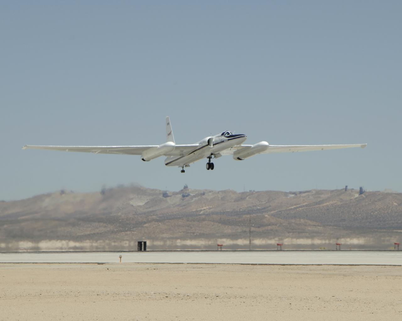
NASA'S ER-2 #806 lifts off from Edwards Air Force Base on a CALIPS/CloudSat validation instrument checkout flight.
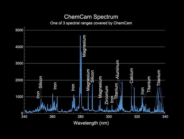
This image provides an example of the type of data collected by the Chemistry and Camera ChemCam instrument on NASA Mars Science Laboratory mission Curiosity rover.
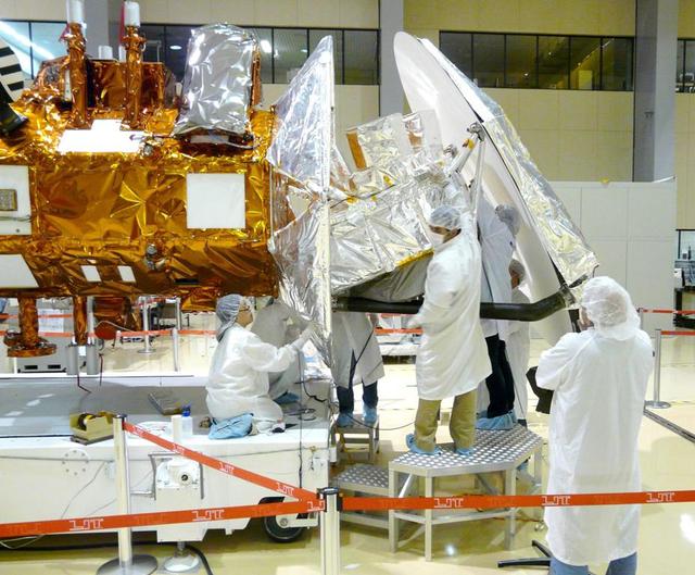
Technicians from NASA Jet Propulsion Laboratory in Pasadena, Calif., install thermal blankets on the Aquarius instrument at Brazil National Institute for Space Research.
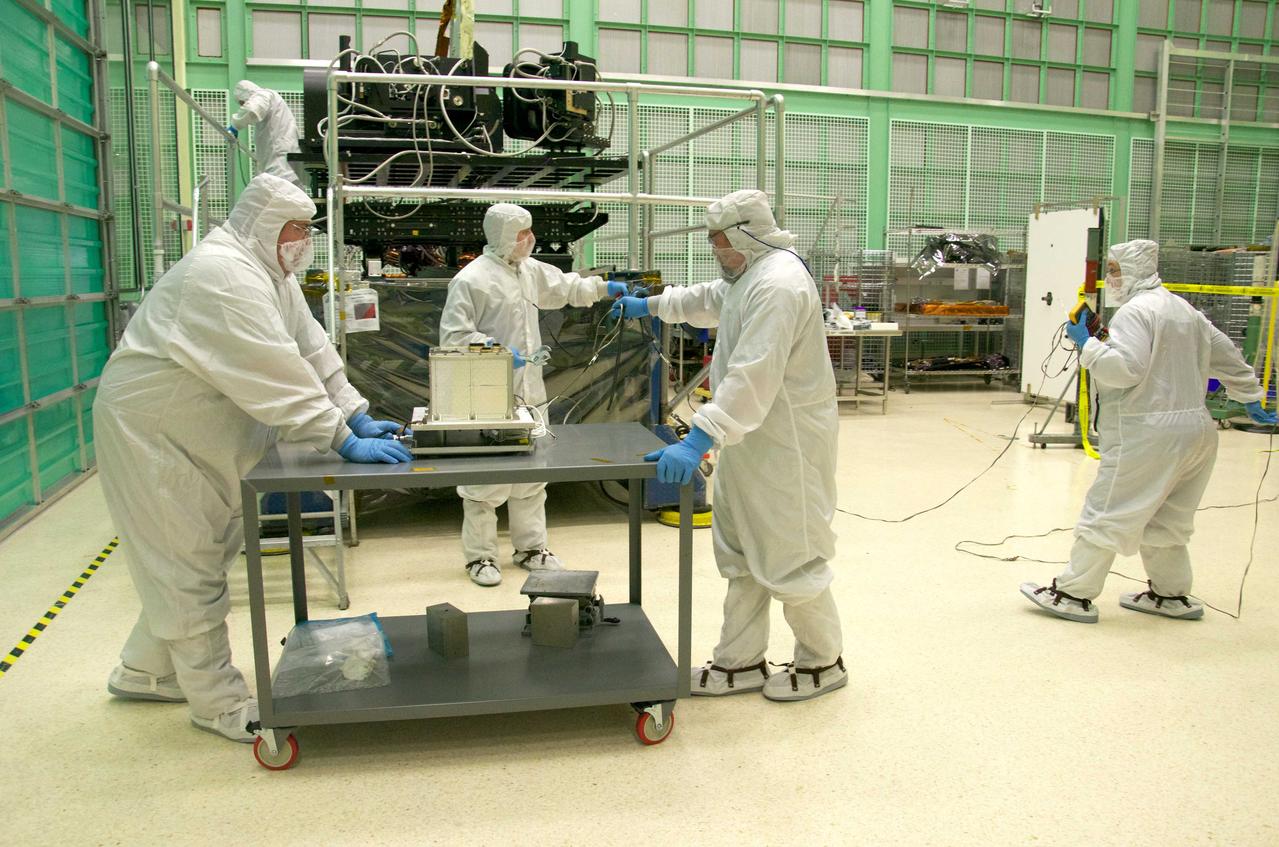
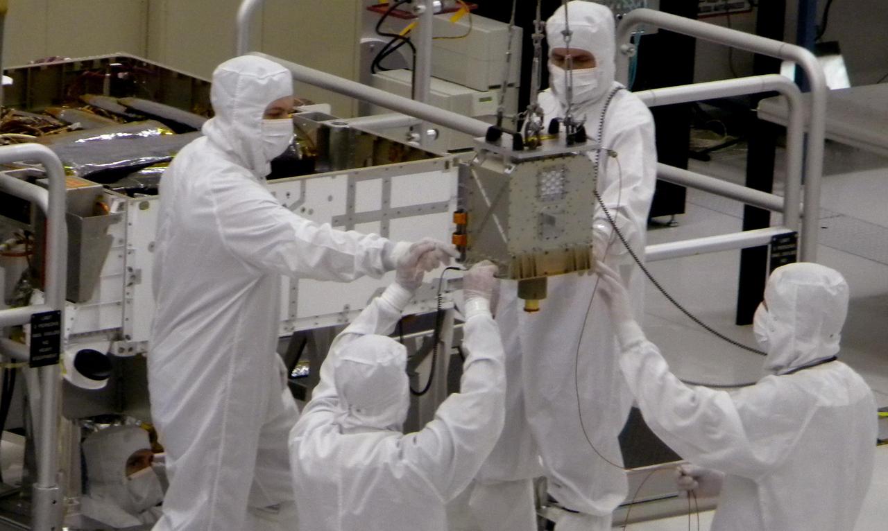
Pete Steigner, and Mike Golob (middle and right) assist an Chris Kolos in carefully moving a TIRS component across the clean room at Goddard. On the far right Robin Knight holds the component's 'grounding strap.' It's used to make sure that any static electricity that could possibly build up while the component is being moved doesn't affect the damage the sensitive electronics. The Thermal Infrared Sensor (TIRS) will fly on the next Landsat satellite, the Landsat Data Continuity Mission (LDCM). TIRS was built on an accelerated schedule at NASA's Goddard Space Flight Center, Greenbelt, Md. and will now be integrated into the LDCM spacecraft at Orbital Science Corp. in Gilbert, Ariz. The Landsat Program is a series of Earth observing satellite missions jointly managed by NASA and the U.S. Geological Survey. Landsat satellites have been consistently gathering data about our planet since 1972. They continue to improve and expand this unparalleled record of Earth's changing landscapes for the benefit of all. For more information on Landsat, visit: <a href="http://www.nasa.gov/landsat" rel="nofollow">www.nasa.gov/landsat</a> Credit: NASA/GSFC/Rebecca Roth <b><a href="http://www.nasa.gov/audience/formedia/features/MP_Photo_Guidelines.html" rel="nofollow">NASA image use policy.</a></b> <b><a href="http://www.nasa.gov/centers/goddard/home/index.html" rel="nofollow">NASA Goddard Space Flight Center</a></b> enables NASA’s mission through four scientific endeavors: Earth Science, Heliophysics, Solar System Exploration, and Astrophysics. Goddard plays a leading role in NASA’s accomplishments by contributing compelling scientific knowledge to advance the Agency’s mission. <b>Follow us on <a href="http://twitter.com/NASA_GoddardPix" rel="nofollow">Twitter</a></b> <b>Like us on <a href="http://www.facebook.com/pages/Greenbelt-MD/NASA-Goddard/395013845897?ref=tsd" rel="nofollow">Facebook</a></b> <b>Find us on <a href="http://instagrid.me/nasagoddard/?vm=grid" rel="nofollow">Instagram</a></b>
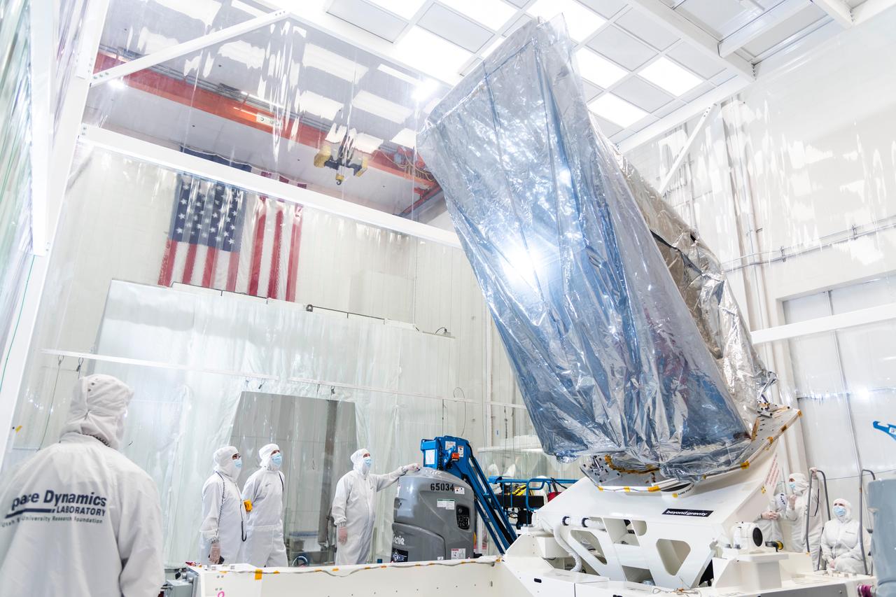
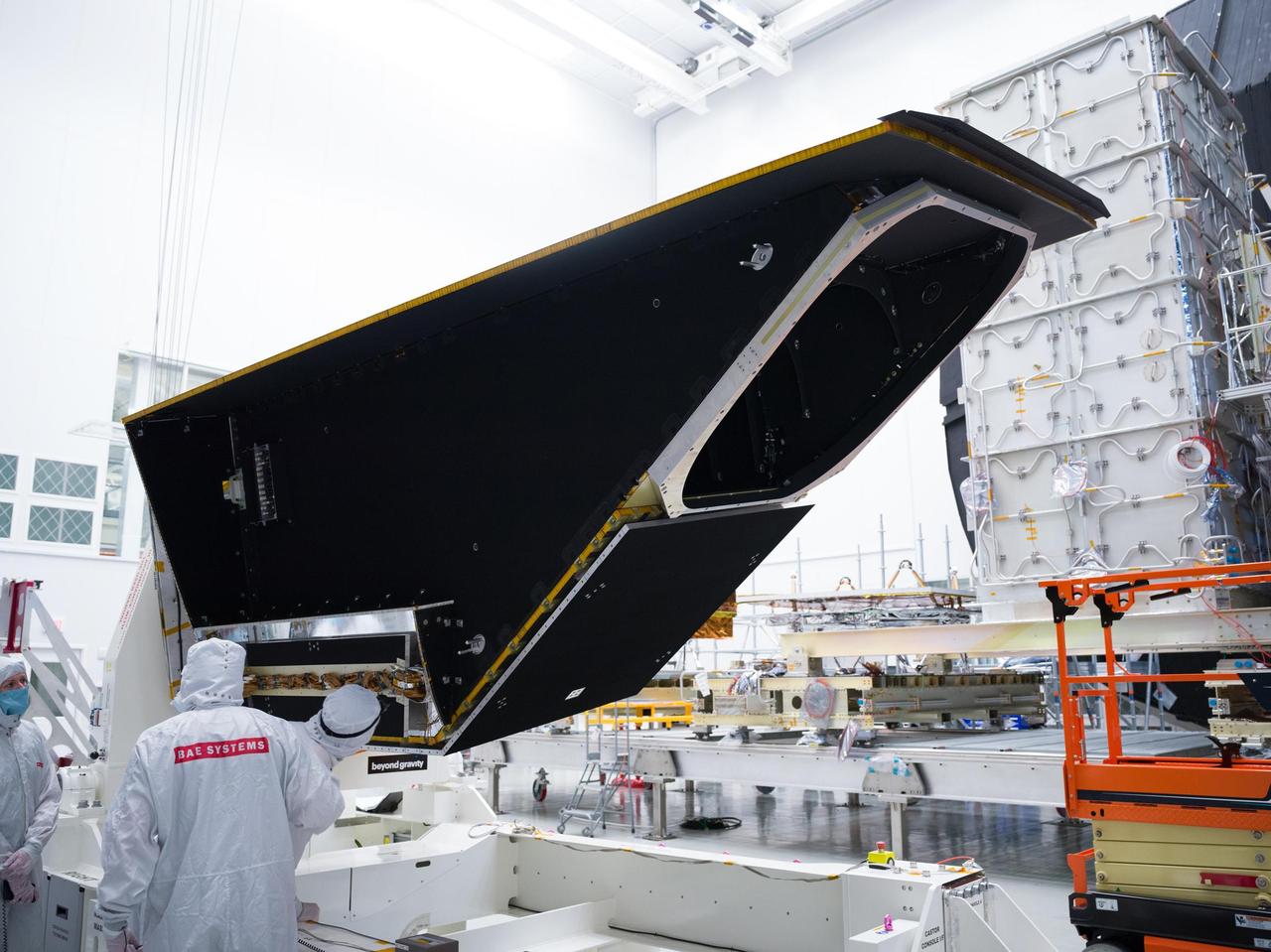
The instrument enclosure for NASA's Near-Earth Object (NEO) Surveyor on May 22, 2025, is seen in a clean room at the Space Dynamics Laboratory (SDL) in Logan, Utah, shortly after arriving from the agency's Jet Propulsion Laboratory in Southern California, where it was assembled. The instrument enclosure is attached to an articulating assembly dolly and wrapped in silver-colored material (composed of a metalized polyester film and a low charging polyethylene laminate) to protect the flight hardware from static electricity and dust particles during transport. The instrument enclosure will house the observatory's scientific instrument, which includes a three-reflection aluminum telescope, state-of-the-art infrared detectors, and an innovative passive cooling system to keep the instrument at cryogenic temperatures. The telescope, which has an aperture of nearly 20 inches (50 centimeters), features detectors sensitive to two infrared wavelengths in which near-Earth objects re-radiate solar heat. The instrument enclosure is designed to ensure heat produced by the spacecraft and instrument during operations doesn't interfere with its infrared observations. As NASA's first space-based detection mission specifically designed for planetary defense, NEO Surveyor will seek out, measure, and characterize the hardest-to-find asteroids and comets that might pose a hazard to Earth. While many near-Earth objects don't reflect much visible light, they glow brightly in infrared light due to heating by the Sun. Targeting launch in late 2027, the NEO Surveyor mission is led by Professor Amy Mainzer at UCLA for NASA's Planetary Defense Coordination Office and is being managed by JPL for the Planetary Missions Program Office at NASA's Marshall Space Flight Center in Huntsville, Alabama. BAE Systems, SDL, and are among the companies that were contracted to build the spacecraft and its instrumentation. The Laboratory for Atmospheric and Space Physics at the University of Colorado Boulder will support operations, and IPAC at Caltech in Pasadena, California, is responsible for producing some of the mission's data products. Caltech manages JPL for NASA. https://photojournal.jpl.nasa.gov/catalog/PIA26589
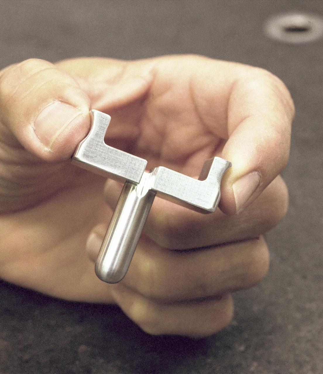
Dryden-built surgical suture instrument
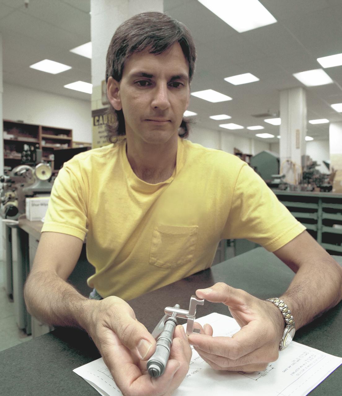
Dryden-built surgical suture instrument
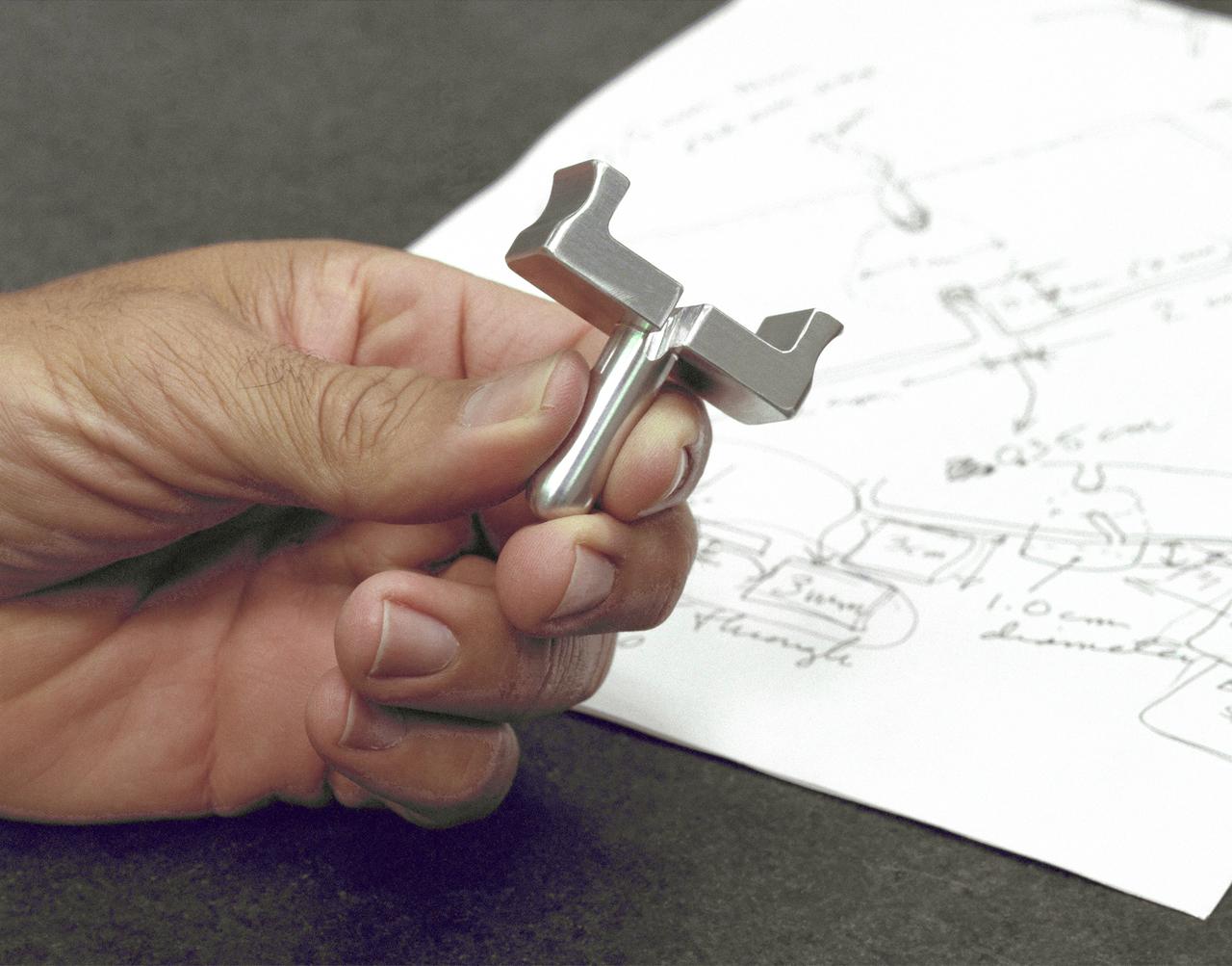
Dryden-built surgical suture instrument
The High-resolution Volatiles and Minerals Moon Mapper (HVM³), seen here, is one of two instruments that will be carried aboard NASA's Lunar Trailblazer. Launching in 2023, the small spacecraft – measuring only 11.5 feet (3.5 meters) wide with its solar panels fully deployed – will detect and map water on the Moon's surface to determine its abundance, location, form, and how it changes over time. HVM³ recently completed a significant milestone in a clean room at NASA's Jet Propulsion Laboratory in Southern California. The high-resolution spectrometer measures the infrared light (with wavelengths from 0.6 to 3.6 microns in size) that is absorbed by water. To make sure the instrument is properly aligned, the Trailblazer team cooled HVM3 down to temperatures it will experience in space and made tiny physical adjustments to make sure all the wavelengths of incoming light arrive at the correct locations on the instrument's detector. Figure A shows several members of the Trailblazer team surrounding the instrument – minus its radiator and electronics – mounted on HVM³'s optical bench assembly while undergoing cold alignment. The assembly was placed inside a thermal vacuum chamber and brought to a cold focal plane operating temperature of about minus 240 degrees Fahrenheit (minus 155 degrees Celsius). The team then measured light of different wavelengths across all of the detector's pixels. Based on the data recorded, the team calculated the small adjustments that needed to be made, took the instrument out of the chamber and made those changes, placed it back into the chamber, and then repeated the steps iteratively until HVM³ was in perfect alignment. With this important step complete, a radiator will next be installed to ensure the instrument maintains optimal operating temperatures while Trailblazer is in orbit around the Moon. Then, vibration tests will be carried out to make sure the spectrometer will stay in alignment after the extreme shaking of launch. Lunar Trailblazer was selected to be part of NASA's SIMPLEx (Small Innovative Missions for Planetary Exploration) program in 2019. The mission is led by Caltech in Pasadena, California, and managed by JPL. https://photojournal.jpl.nasa.gov/catalog/PIA25252
Instrumentation in 16 Foot Wind Tunnel manometer boards
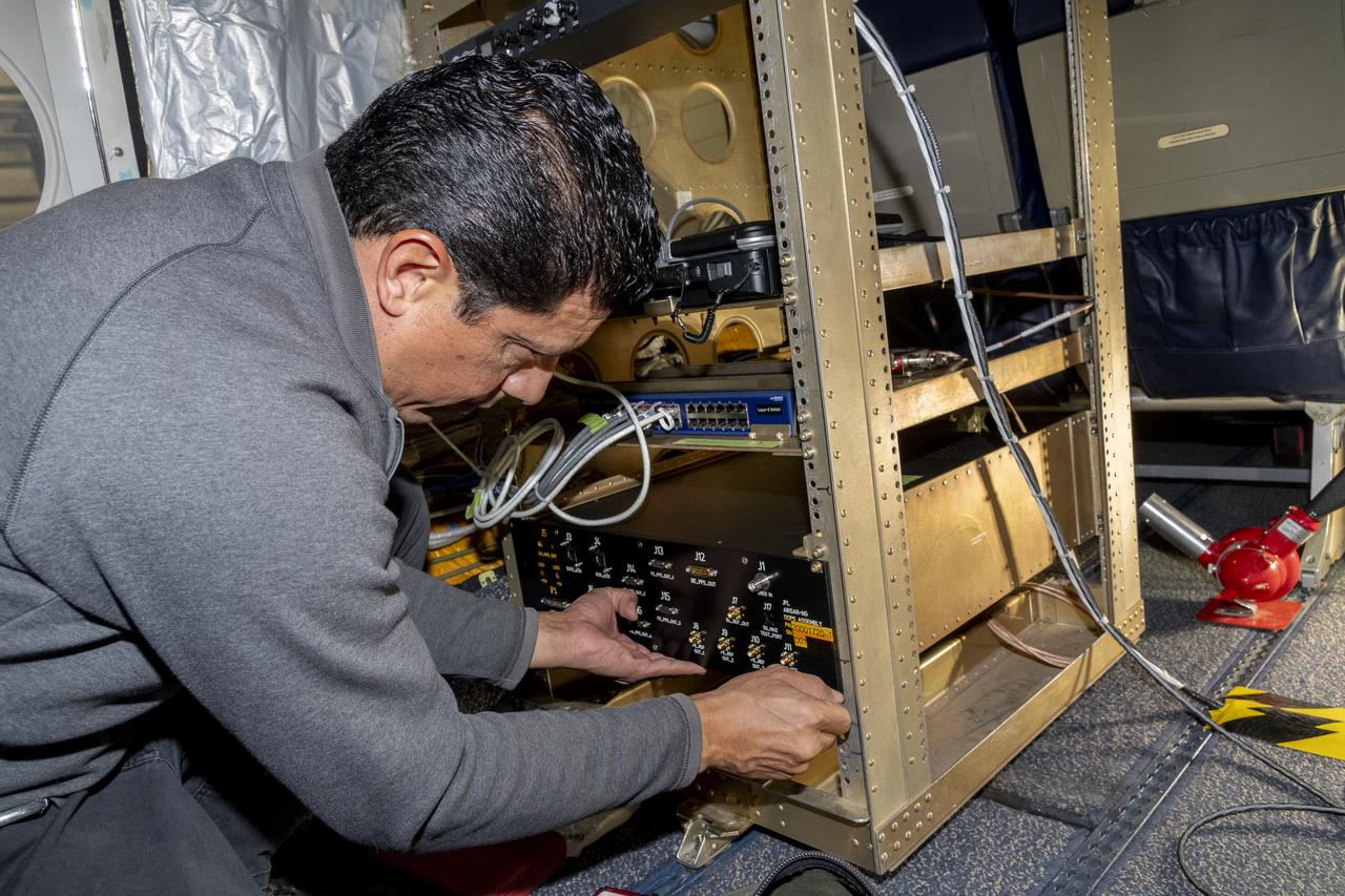
Jose “Manny” Rodriguez adjusts the Soxnav instrument onboard the G-IV aircraft in December 2024. As part of the team of experts, Rodriguez ensures that the electronic components of this instrument are installed efficiently. His expertise will help bring the innovative navigational guidance of the Soxnav system to the G-IV and the wider airborne science fleet at NASA. Precision guidance provided by the Soxnav enables research aircraft like the G-IV to collect more accurate, more reliable Earth science data to scientists on the ground.
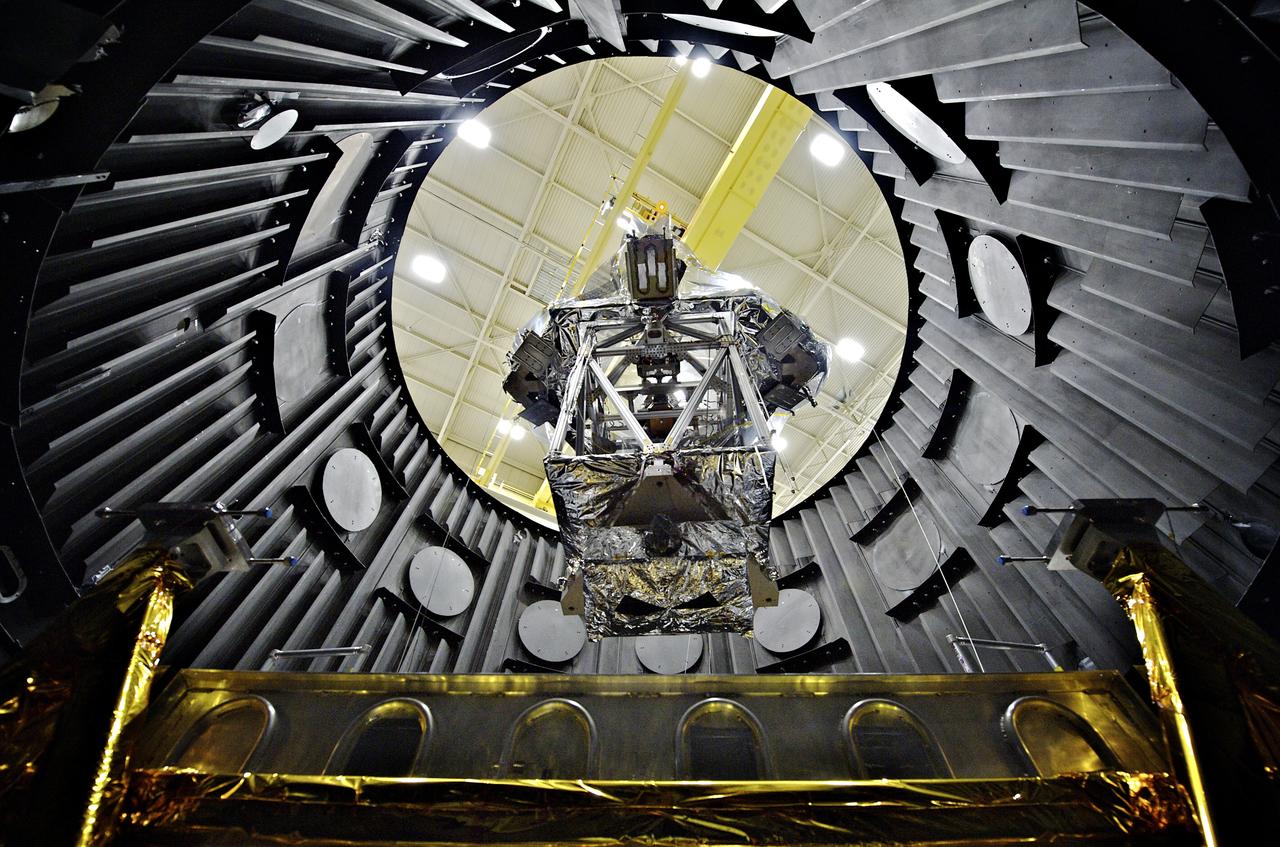
The OTE (Optical Telescope Element) Simulator or OSIM wrapped in a silver blanket on a platform, being lowered down into a vacuum chamber (called the Space Environment Simulator, or SES) by a crane to be tested to withstand the cold temperatures of space. More information: <a href="http://www.nasa.gov/topics/technology/features/webb-osim.html" rel="nofollow">www.nasa.gov/topics/technology/features/webb-osim.html</a> Credit: NASA Goddard/Chris Gunn <b><a href="http://www.nasa.gov/audience/formedia/features/MP_Photo_Guidelines.html" rel="nofollow">NASA image use policy.</a></b> <b><a href="http://www.nasa.gov/centers/goddard/home/index.html" rel="nofollow">NASA Goddard Space Flight Center</a></b> enables NASA’s mission through four scientific endeavors: Earth Science, Heliophysics, Solar System Exploration, and Astrophysics. Goddard plays a leading role in NASA’s accomplishments by contributing compelling scientific knowledge to advance the Agency’s mission. <b>Follow us on <a href="http://twitter.com/NASA_GoddardPix" rel="nofollow">Twitter</a></b> <b>Like us on <a href="http://www.facebook.com/pages/Greenbelt-MD/NASA-Goddard/395013845897?ref=tsd" rel="nofollow">Facebook</a></b> <b>Find us on <a href="http://instagrid.me/nasagoddard/?vm=grid" rel="nofollow">Instagram</a></b>
The instrument enclosure for NASA's Near-Earth Object Surveyor is prepared for environmental testing inside the historic Chamber A in the Space Environment Simulation Laboratory at the agency's Johnson Space Center in Houston in December 2024. Mounted to its articulating platform, on which it was securely positioned during assembly, the 12-foot-long (3.7-meter-long) angular structure was inspected by technicians before being placed inside the testing chamber. Figure A shows the reflective side of the instrument enclosure as it was rotated on the assembly dolly before being transferred to a testing platform. The cavernous opening to Chamber A is in the background. The instrument enclosure is designed to protect the spacecraft's infrared telescope while also removing heat from it during operations. After environmental testing was completed, the enclosure returned to NASA's Jet Propulsion Laboratory in Southern California for further work, after which it will ship to the Space Dynamics Laboratory (SDL) in Logan, Utah, and be joined to the telescope. Both the instrument enclosure and telescope were assembled at JPL. As NASA's first space-based detection mission specifically designed for planetary defense, NEO Surveyor will seek out, measure, and characterize the hardest-to-find asteroids and comets that might pose a hazard to Earth. While many near-Earth objects don't reflect much visible light, they glow brightly in infrared light due to heating by the Sun. The spacecraft's telescope, which has an aperture of nearly 20 inches (50 centimeters), features detectors sensitive to two infrared wavelengths in which near-Earth objects re-radiate solar heat. Targeting launch in late 2027, the NEO Surveyor mission is led by Prof. Amy Mainzer at UCLA for NASA's Planetary Defense Coordination Office and is being managed by JPL for the Planetary Missions Program Office at NASA's Marshall Space Flight Center in Huntsville, Alabama. BAE Systems, SDL, and Teledyne are among the companies that were contracted to build the spacecraft and its instrumentation. The Laboratory for Atmospheric and Space Physics at the University of Colorado Boulder will support operations, and Caltech/IPAC in Pasadena, California, is responsible for producing some of the mission's data products. Caltech manages JPL for NASA. https://photojournal.jpl.nasa.gov/catalog/PIA26582
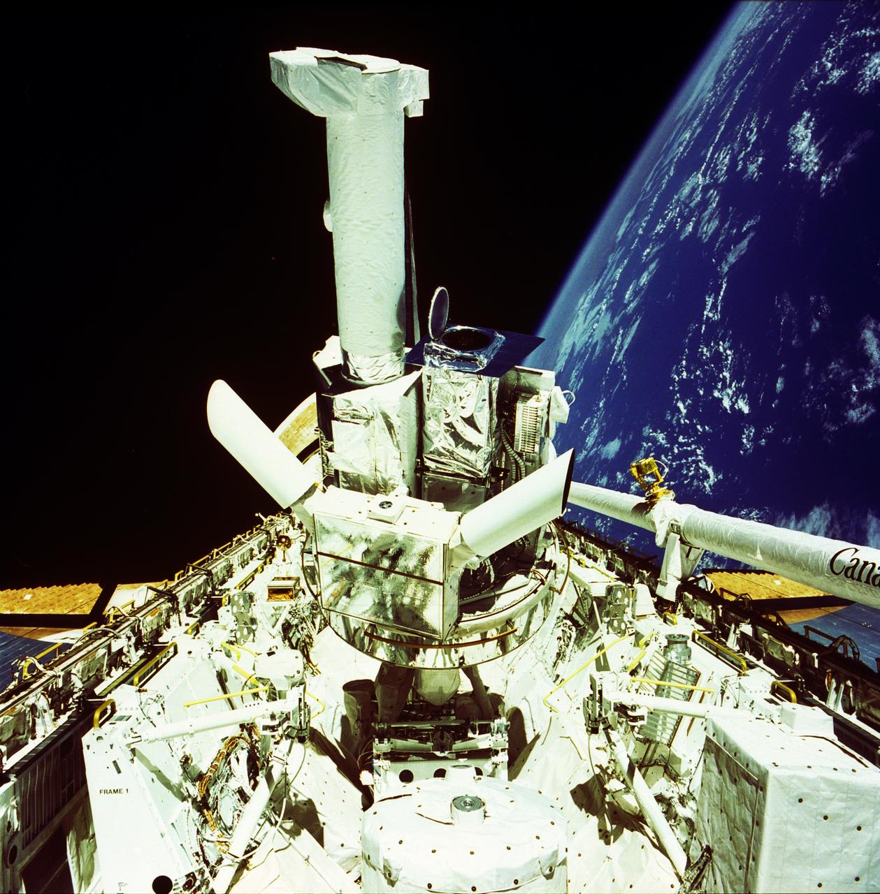
This photograph shows the Instrument Pointing System (IPS) for Spacelab-2 being deployed in the cargo bay of the Space Shuttle Orbiter Challenger. The European Space Agency (ESA) developed this irnovative pointing system for the Spacelab program. Previously, instruments were pointed toward particular celestial objects or areas by maneuvering the Shuttle to an appropriate attitude. The IPS could aim instruments more accurately than the Shuttle and kept them fixed on a target as the Shuttle moved. On the first pallet, three solar instruments and one atmospheric instrument were mounted on the IPS. Spacelab-2 was the first pallet-only mission. One of the goals of the mission was to verify that the pallets' configuration was satisfactory for observations and research. Except for two biological experiments and an experiment that uses ground-based instruments, the Spacelab-2 scientific instruments needed direct exposure to space. The Spacelab-2 mission was designed to capitalize on the Shuttle-Spacelab capabilities to carry very large instruments, launch and retrieve satellites, and point several instruments independently with accuracy and stability. Spacelab-2 (STS-51F, 19th Shuttle mission) was launched on July 29, 1985 aboard the Space Shuttle Orbiter Challenger. The Marshall Space Flight Center had overall management responsibilities of the Spacelab missions.
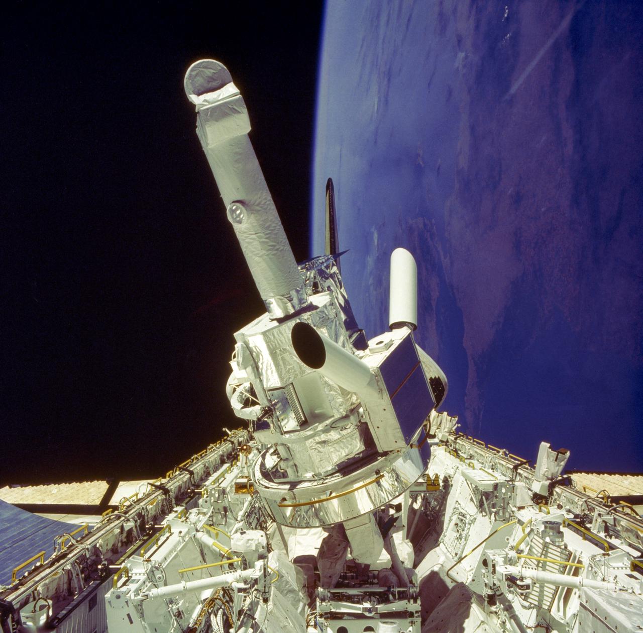
This photograph shows the Instrument Pointing System (IPS) for Spacelab-2 being deployed in the cargo bay of the Space Shuttle Orbiter Challenger. The European Space Agency (ESA) developed this irnovative pointing system for the Spacelab program. Previously, instruments were pointed toward particular celestial objects or areas by maneuvering the Shuttle to an appropriate attitude. The IPS could aim instruments more accurately than the Shuttle and kept them fixed on a target as the Shuttle moved. On the first pallet, three solar instruments and one atmospheric instrument were mounted on the IPS. Spacelab-2 was the first pallet-only mission. One of the goals of the mission was to verify that the pallets' configuration was satisfactory for observations and research. Except for two biological experiments and an experiment that used ground-based instruments, the Spacelab-2 scientific instruments needed direct exposure to space. The Spacelab-2 mission was designed to capitalize on the Shuttle-Spacelab capabilities to carry very large instruments, launch and retrieve satellites, and point several instruments independently with accuracy and stability. Spacelab-2 (STS-51F, 19th Shuttle mission) was launched on July 29, 1985 aboard the Space Shuttle Orbiter Challenger. The Marshall Space Flight Center had overall management responsibilities of the Spacelab missions.
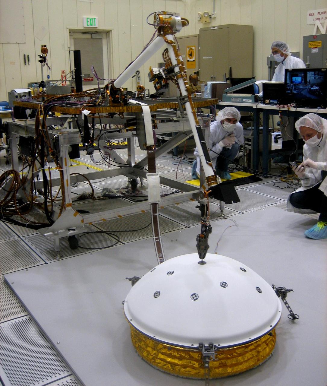
In the weeks after NASA's InSight mission reaches Mars in September 2016, the lander's arm will lift two key science instruments off the deck and place them onto the ground. This image shows testing of InSight's robotic arm inside a clean room at NASA's Jet Propulsion Laboratory, Pasadena, California, about two years before it will perform these tasks on Mars. InSight -- an acronym for Interior Exploration using Seismic Investigations, Geodesy and Heat Transport -- will launch in March 2016. It will study the interior of Mars to improve understanding of the processes that formed and shaped rocky planets, including Earth. One key instrument that the arm will deploy is the Seismic Experiment for Interior Structure, or SEIS. It is from France's national space agency (CNES), with components from Germany, Switzerland, the United Kingdom and the United States. In this scene, the arm has just deployed a test model of a protective covering for SEIS, the instrument's wind and thermal shield. The shield's purpose is to lessen disturbances that weather would cause to readings from the sensitive seismometer. Note: After thorough examination, NASA managers have decided to suspend the planned March 2016 launch of the Interior Exploration using Seismic Investigations Geodesy and Heat Transport (InSight) mission. The decision follows unsuccessful attempts to repair a leak in a section of the prime instrument in the science payload. http://photojournal.jpl.nasa.gov/catalog/PIA19144

Researchers Anna Noe and Eric Altman check out the Doppler Aerosol Wind Lidar (DAWN), an airborne instrument that uses pulsed lasers to detect the movement of atmospheric aerosols such as dust or sea salt. In detecting those movements, it can profile wind vector — both speed and direction. Researchers are testing DAWNs capabilities during flights over the eastern Pacific.
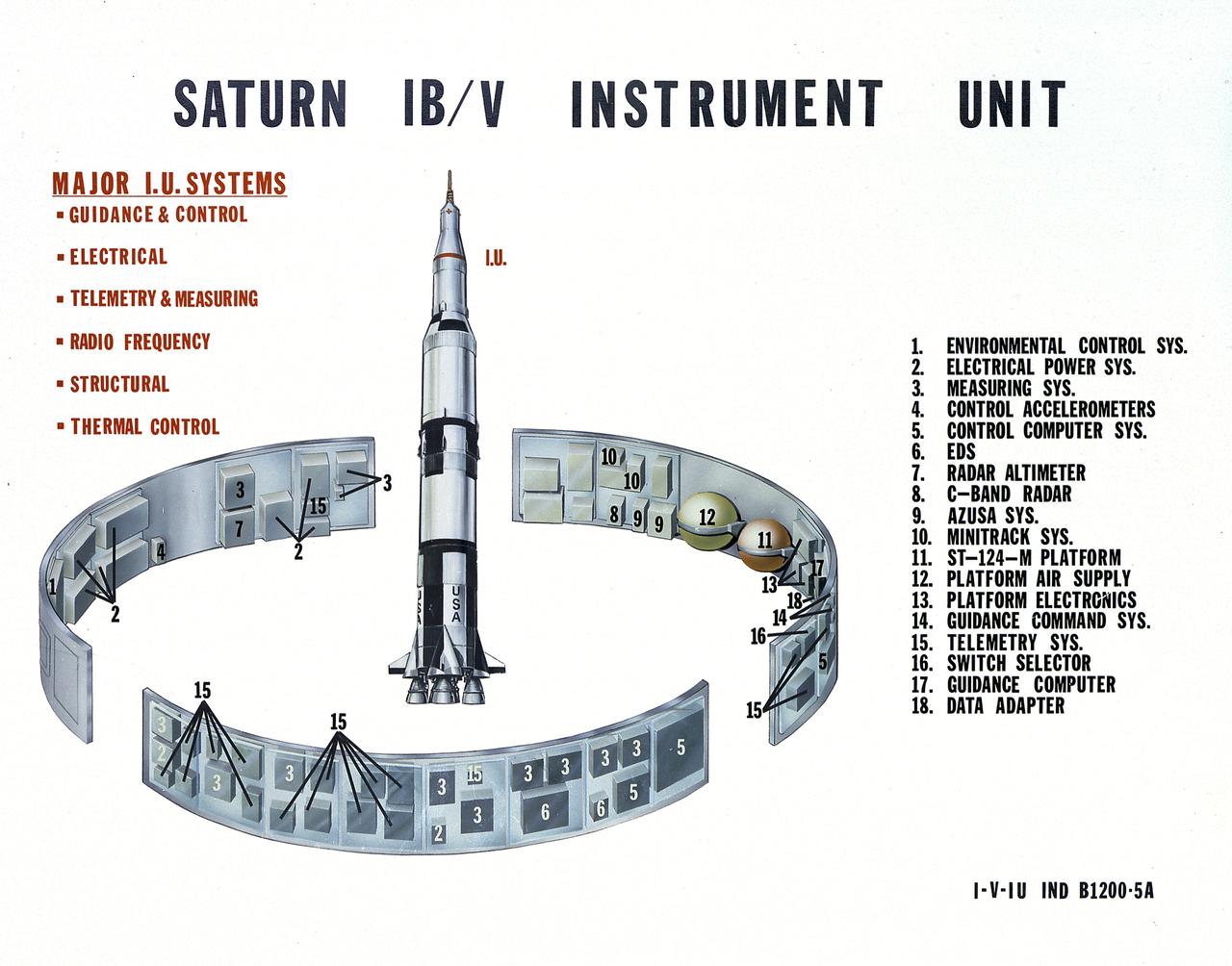
This undated chart provides a description of the Saturn IB and Saturn V's Instrument Unit (IU) and its major components. Designed by NASA at the Marshall Space Flight Center (MSFC), the Instrument Unit, sandwiched between the S-IVB stage and the Apollo spacecraft, served as the Saturn's "nerve center" providing guidance and control, command and sequence of vehicle functions, telemetry, and environmental control.
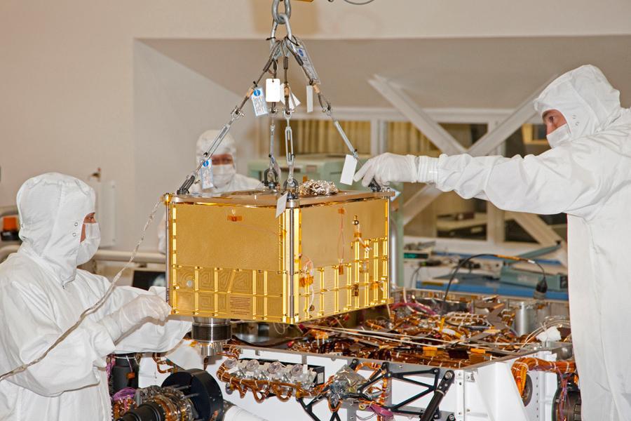
In this photograph, technicians and engineers inside a clean room at NASA Jet Propulsion Laboratory, Pasadena, Calif., position NASA Sample Analysis at Mars SAM above the mission Mars rover, Curiosity, for installing the instrument.
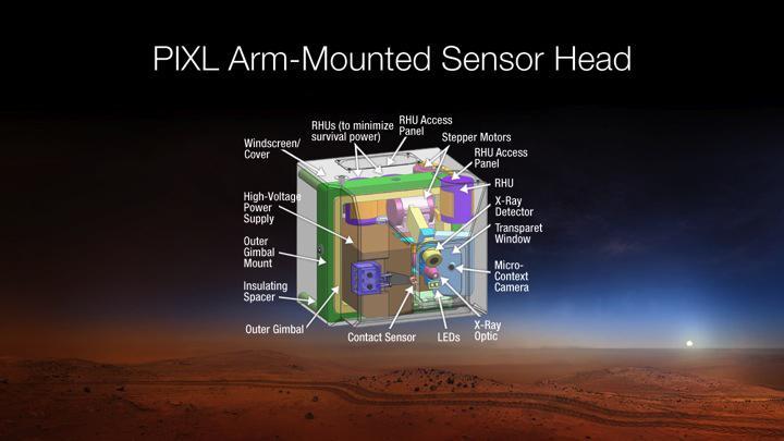
This diagram depicts the sensor head of the Planetary Instrument for X-RAY Lithochemistry, or PIXL, which has been selected as one of seven investigations for the payload of NASA Mars 2020 rover mission.
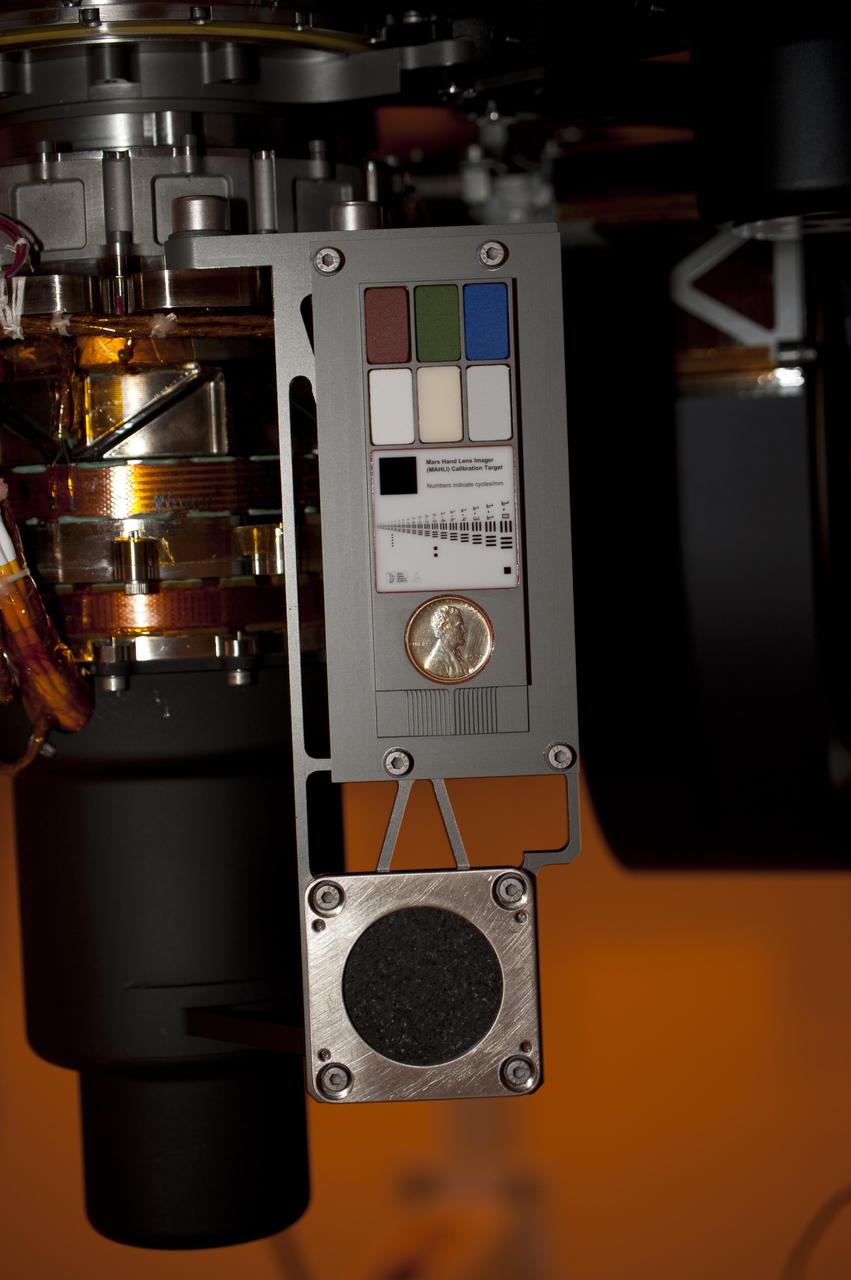
Two instruments at the end of the robotic arm on NASA Mars rover Curiosity will use calibration targets attached to a shoulder joint of the arm. The penny is a size reference giving the public a familiar object for perceiving size on Mars easily.
Members of NASA Mars Science Laboratory team carefully steer the hoisted Chemistry and Mineralogy CheMin instrument during its June 15, 2010, installation into the mission Mars rover, Curiosity.
In this photograph, technicians and engineers inside a clean room at NASA Jet Propulsion Laboratory, Pasadena, Calif., position NASA Sample Analysis at Mars SAM above the mission Mars rover, Curiosity, for installing the instrument.
The Sample Analysis at Mars SAM instrument for NASA Mars Science Laboratory mission will study chemistry of rocks, soil and air as the mission rover, Curiosity, investigates Gale Crater on Mars.
An instrument suite that will analyze the chemical ingredients in samples of Martian atmosphere, rocks and soil during the mission of NASA Mars rover Curiosity, is shown here during assembly at NASA Goddard Space Flight Center, Greenbelt, Md., in 2010.
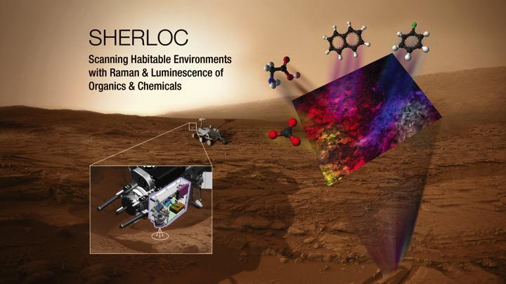
This illustration depicts the mechanism and conceptual research targets for an instrument named SHERLOC, which has been selected as one of seven investigations for the payload of NASA Mars 2020 rover mission.
The Mars Climate Sounder instrument, shown here prior to its installation onto NASA Mars Reconnaissance Orbiter for the mission 2006 launch, will get a similar-looking sibling at Mars in 2016.
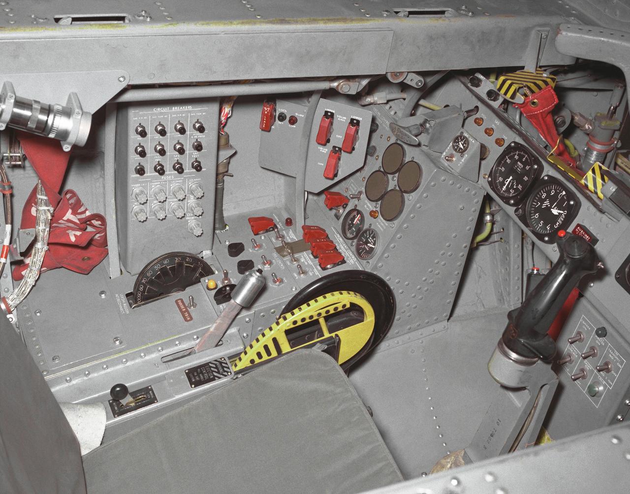
This photo shows the left side cockpit instrumentation panel of the M2-F2 Lifting Body. The success of Dryden's M2-F1 program led to NASA's development and construction of two heavyweight lifting bodies based on studies at NASA's Ames and Langley research centers -- the M2-F2 and the HL-10, both built by the Northrop Corporation. The "M" refers to "manned" and "F" refers to "flight" version. "HL" comes from "horizontal landing" and 10 is for the tenth lifting body model to be investigated by Langley. The first flight of the M2-F2 -- which looked much like the "F1" -- was on July 12, 1966. Milt Thompson was the pilot. By then, the same B-52 used to air launch the famed X-15 rocket research aircraft was modified to also carry the lifting bodies. Thompson was dropped from the B-52's wing pylon mount at an altitude of 45,000 feet on that maiden glide flight. The M2-F2 weighed 4,620 pounds, was 22 feet long, and had a width of about 10 feet. On May 10, 1967, during the sixteenth glide flight leading up to powered flight, a landing accident severely damaged the vehicle and seriously injured the NASA pilot, Bruce Peterson. NASA pilots and researchers realized the M2-F2 had lateral control problems, even though it had a stability augmentation control system. When the M2-F2 was rebuilt at Dryden and redesignated the M2-F3, it was modified with an additional third vertical fin -- centered between the tip fins -- to improve control characteristics. The M2-F2/F3 was the first of the heavy-weight, entry-configuration lifting bodies. Its successful development as a research test vehicle answered many of the generic questions about these vehicles. NASA donated the M2-F3 vehicle to the Smithsonian Institute in December 1973. It is currently hanging in the Air and Space Museum along with the X-15 aircraft number 1, which was its hangar partner at Dryden from 1965 to 1969.
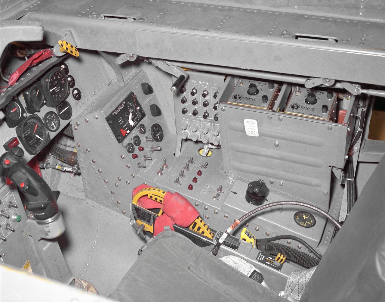
This photo shows the right side cockpit instrumentation panel of the M2-F2 Lifting Body. The success of Dryden's M2-F1 program led to NASA's development and construction of two heavyweight lifting bodies based on studies at NASA's Ames and Langley research centers -- the M2-F2 and the HL-10, both built by the Northrop Corporation. The "M" refers to "manned" and "F" refers to "flight" version. "HL" comes from "horizontal landing" and 10 is for the tenth lifting body model to be investigated by Langley. The first flight of the M2-F2 -- which looked much like the "F1" -- was on July 12, 1966. Milt Thompson was the pilot. By then, the same B-52 used to air launch the famed X-15 rocket research aircraft was modified to also carry the lifting bodies. Thompson was dropped from the B-52's wing pylon mount at an altitude of 45,000 feet on that maiden glide flight. The M2-F2 weighed 4,620 pounds, was 22 feet long, and had a width of about 10 feet. On May 10, 1967, during the sixteenth glide flight leading up to powered flight, a landing accident severely damaged the vehicle and seriously injured the NASA pilot, Bruce Peterson. NASA pilots and researchers realized the M2-F2 had lateral control problems, even though it had a stability augmentation control system. When the M2-F2 was rebuilt at Dryden and redesignated the M2-F3, it was modified with an additional third vertical fin -- centered between the tip fins -- to improve control characteristics. The M2-F2/F3 was the first of the heavy-weight, entry-configuration lifting bodies. Its successful development as a research test vehicle answered many of the generic questions about these vehicles. NASA donated the M2-F3 vehicle to the Smithsonian Institute in December 1973. It is currently hanging in the Air and Space Museum along with the X-15 aircraft number 1, which was its hangar partner at Dryden from 1965 to 1969.

The Landsat 9 instrument cover is removed from the spacecraft inside the Integrated Processing Facility (IPF) at Vandenberg Space Force Base in California.