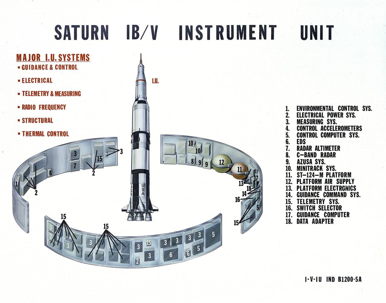
This undated chart provides a description of the Saturn IB and Saturn V's Instrument Unit (IU) and its major components. Designed by NASA at the Marshall Space Flight Center (MSFC), the Instrument Unit, sandwiched between the S-IVB stage and the Apollo spacecraft, served as the Saturn's "nerve center" providing guidance and control, command and sequence of vehicle functions, telemetry, and environmental control.
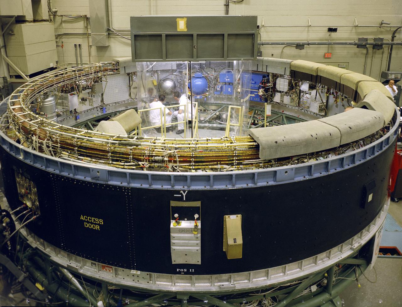
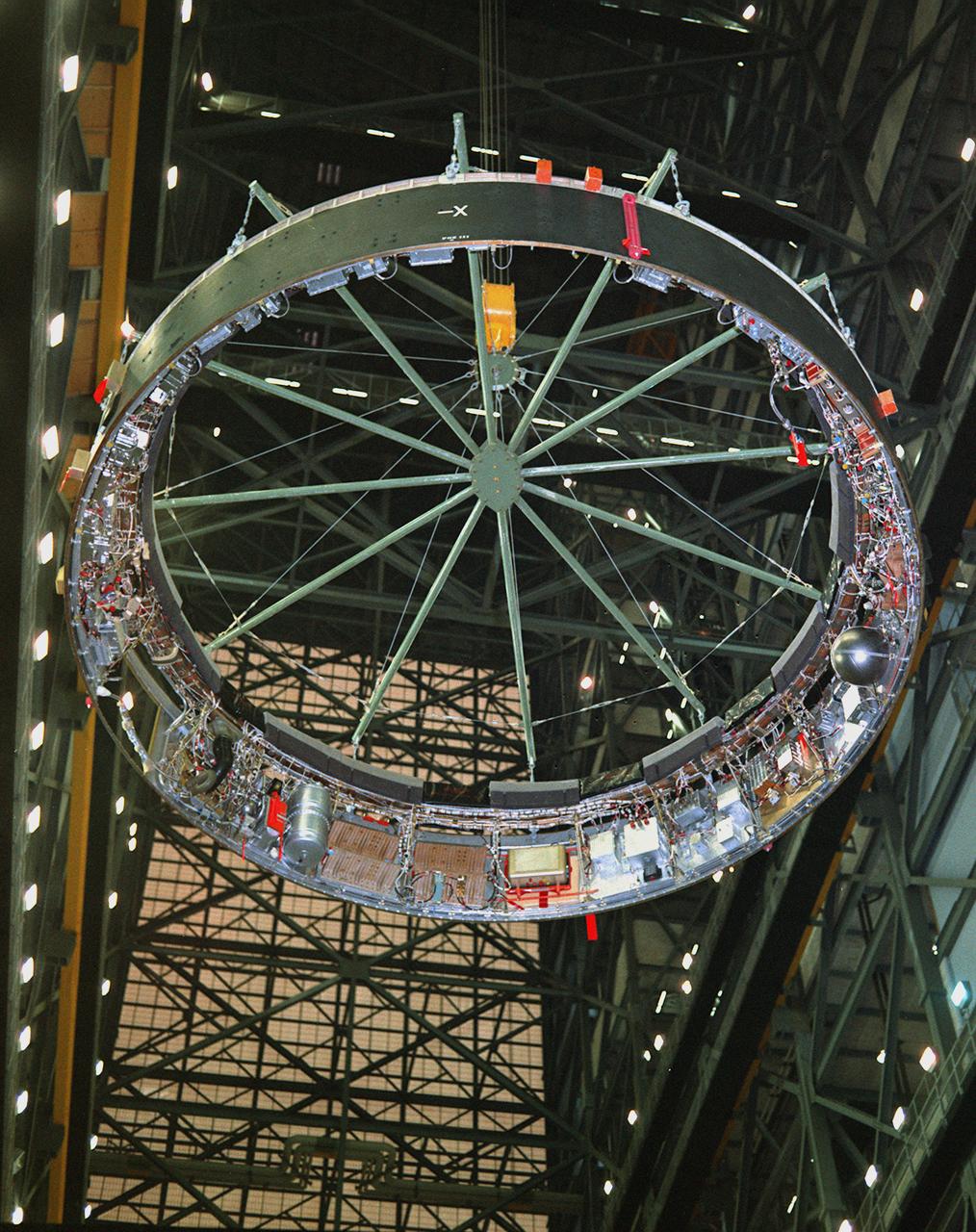
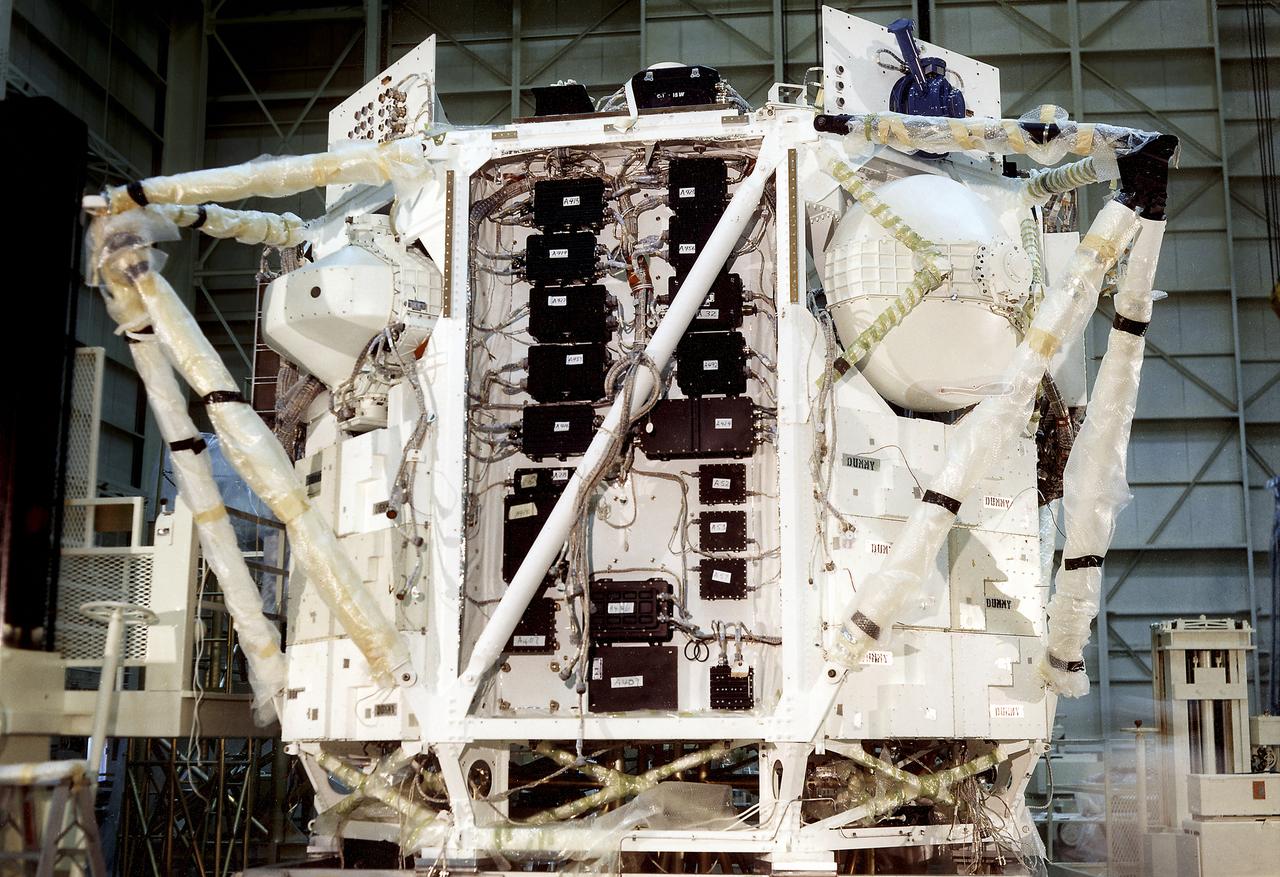
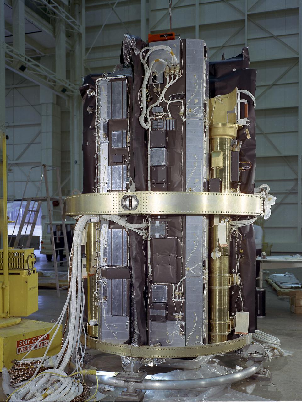
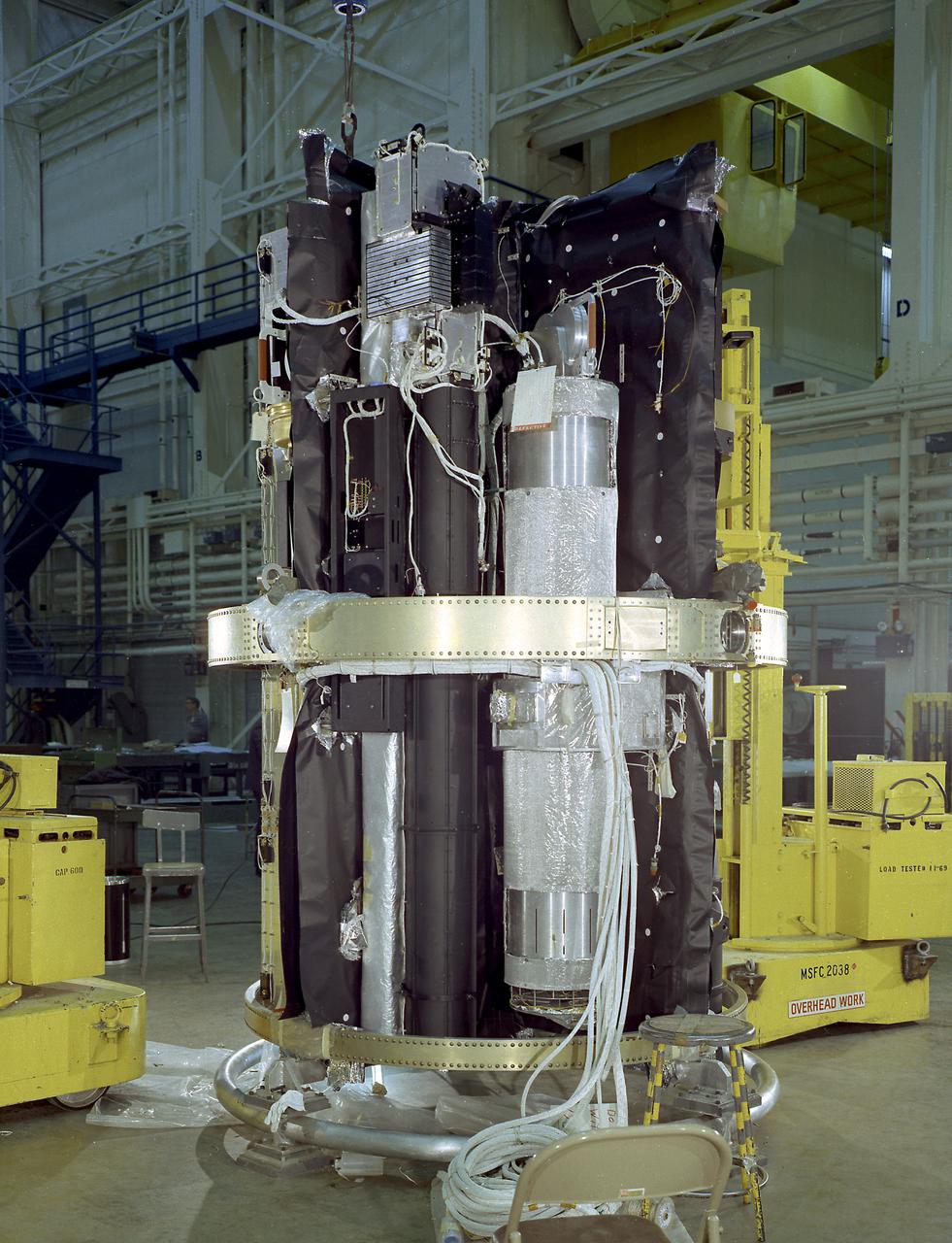
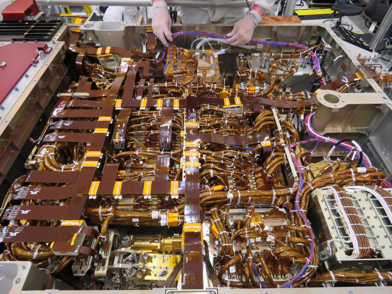
This view depicts engineers conducting a system test on the Saturn V instrument unit (IU) at International Business Machines (IBM) in Huntsville, Alabama. IBM is a prime contractor for development and fabrication of the IU. The IU is vital to the proper flight of the vehicle. It contains navigation, guidance, control, and sequencing equipment for the launch vehicle. Three-feet tall, twenty-one feet in diameter, and weighing about 4,000 pounds, the IU is mounted atop the S-IVB (third) stage, between the S-IVB stage and the Apollo spacecraft.
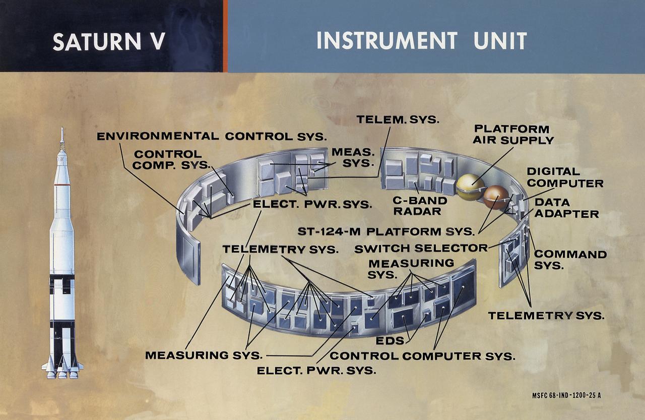
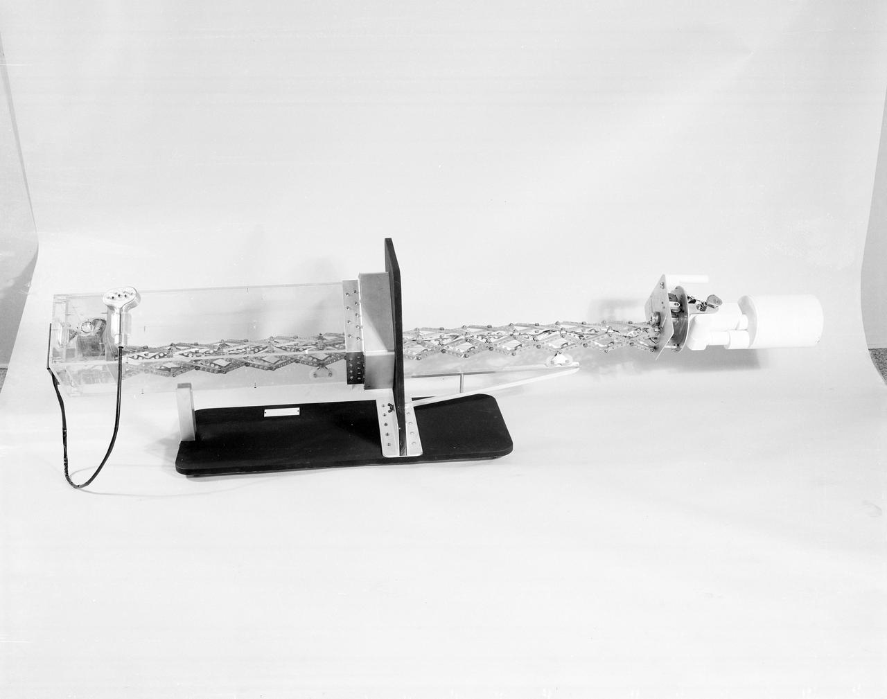
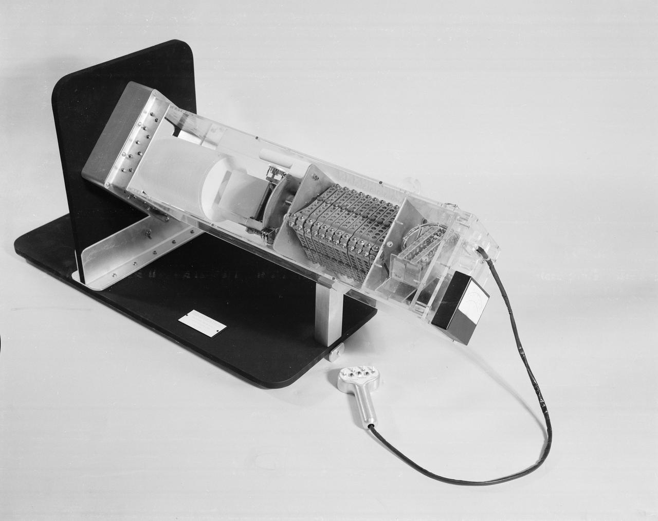
This illustration shows the major components of the instrument unit (IU). Developed and manufactured by International Business Machines, the IU is 3 feet high and 21 feet in diameter and mounted atop an S-IVB, between the third stage and the Apollo spacecraft. It contained the computers, all guidance, control, and sequencing equipment to keep the the launch vehicle properly functioning and on its course. The IU was essentially the same in both the Saturn IB and the Saturn V.
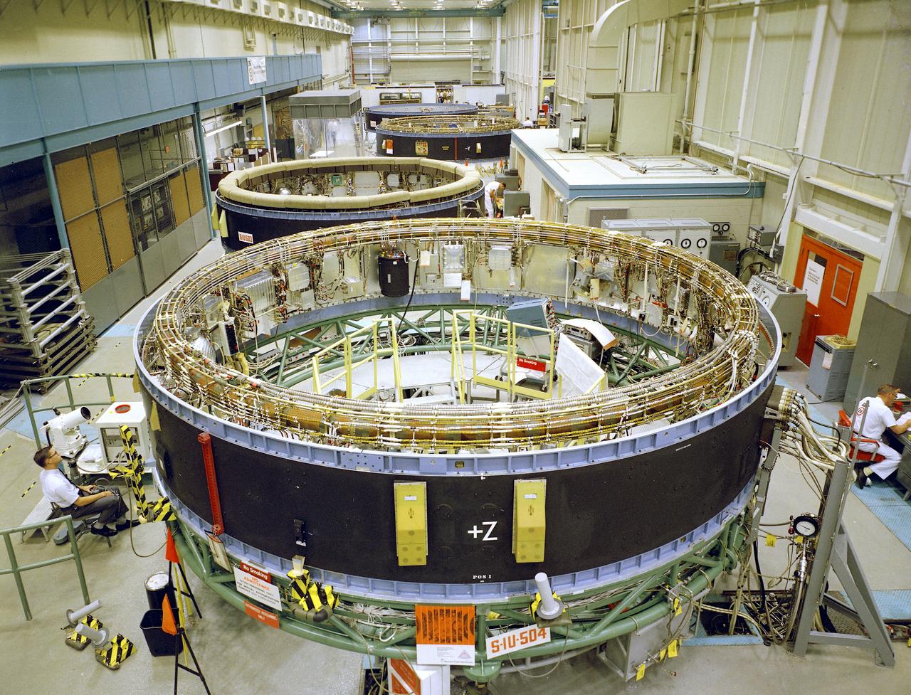
This is a view of the Saturn V instrument unit (IU) being manufactured in the east high bay at International Business Machines (IBM) in Huntsville, Alabama. IBM is a prime contractor for development and fabrication of the IU. The IU is vital to the proper flight of the vehicle. It contains navigation, guidance, control, and sequencing equipment for the launch vehicle. Three feet tall, twenty-one feet in diameter, and weighing about 4,000 pounds, the IU is mounted atop the S-IVB (third) stage, between the S-IVB stage and the Apollo spacecraft.
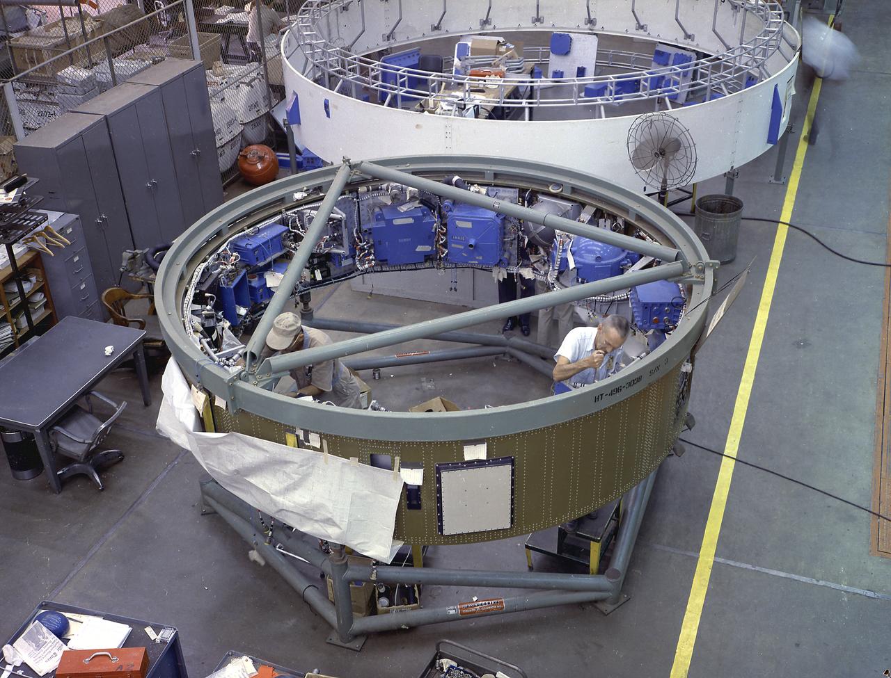
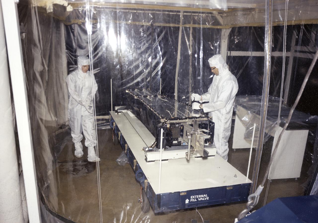
This image depicts a high angle view of technicians working on the instrument unit (IU) component assembly for the SA-8 mission in Marshall Space Flight Center's building 4705. A thin, circular structure, only 1-meter high and 7.6 meters in diameter, the IU was sandwiched between the S-IV and Apollo spacecraft. Packed inside were the computers, gyroscopes, and assorted black boxes necessary to keep the launch vehicle properly functioning and on its course.
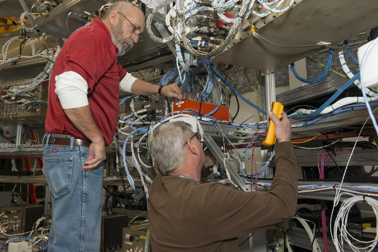
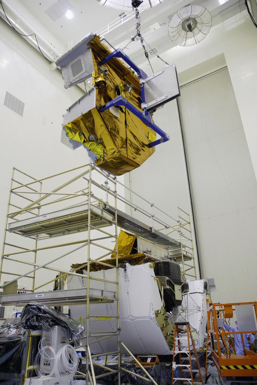
From left, Wayne Arrington, a Boeing Company technician, and Steve Presti, a mechanical technician at NASA's Marshall Space Flight Center in Huntsville, Ala., install Developmental Flight Instrumentation Data Acquisition Units in Marshall's Systems Integration and Test Facility. The units are part of NASA's Space Launch System (SLS) core stage avionics, which will guide the biggest, most powerful rocket in history to deep space missions. When completed, the core stage will be more than 200 feet tall and store cryogenic liquid hydrogen and liquid oxygen that will feed the vehicle's RS-25 engines. The hardware, software and operating systems for the SLS are arranged in flight configuration in the facility for testing. The new Data Acquisition Units will monitor vehicle behavior in flight -- like acceleration, thermal environments, shock and vibration. That data will then be used to validate previous ground tests and analyses models that were used in the development of the SLS vehicle.
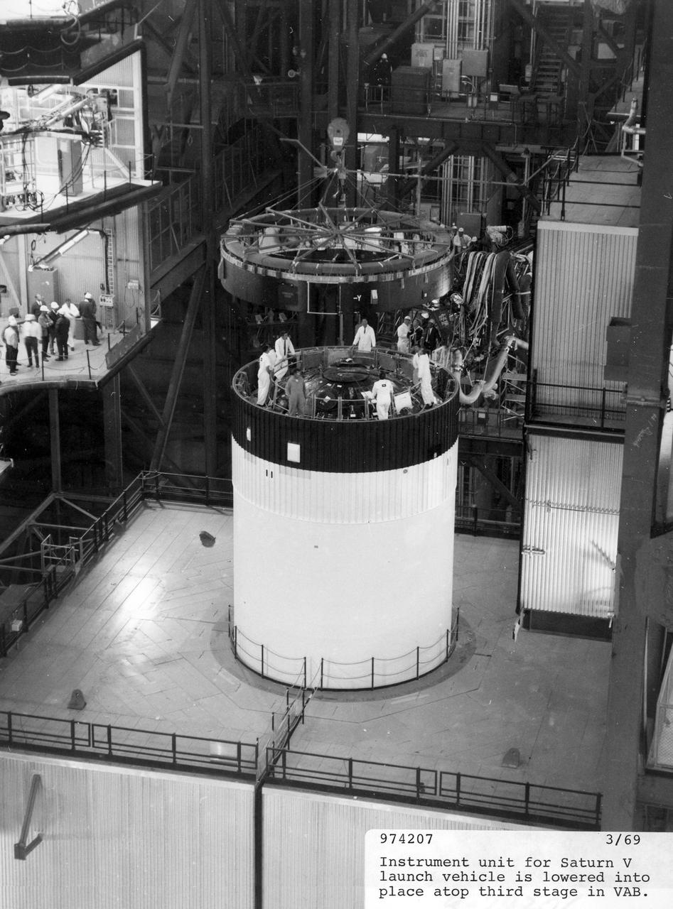
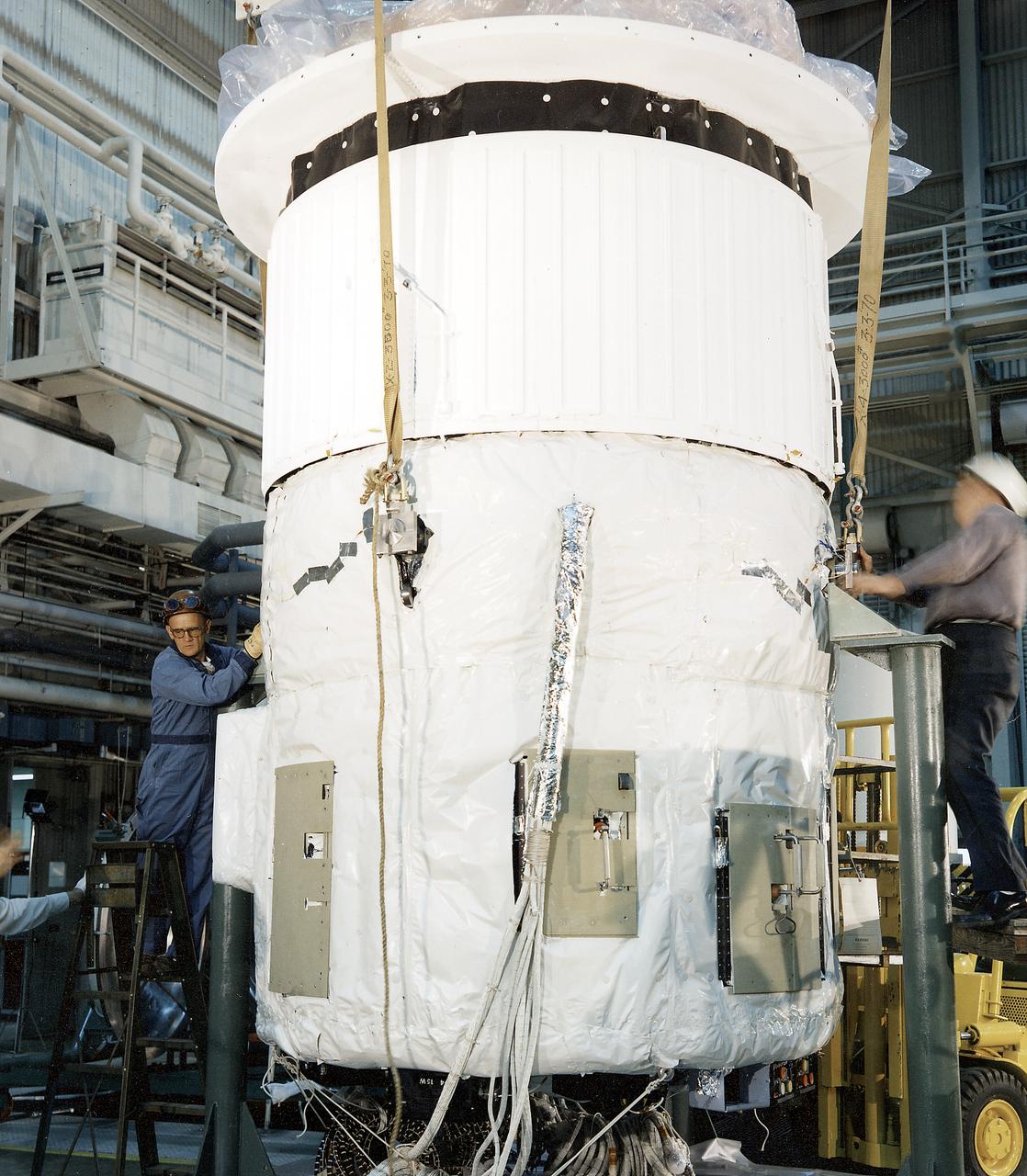
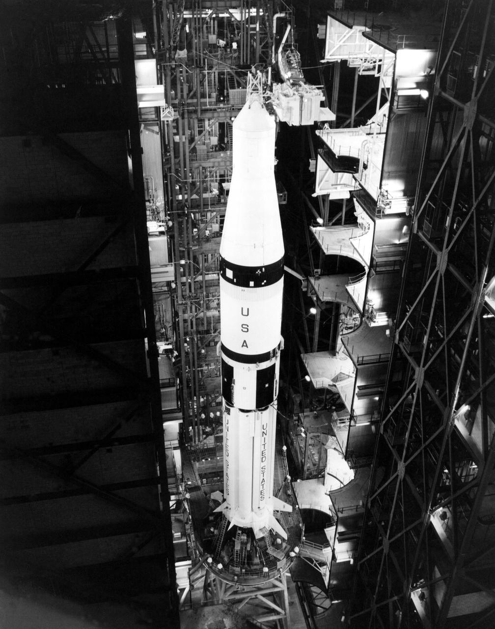
The instrument unit for the Saturn V launch vehicle, AS-506, used to propel the Apollo 11 lunar landing mission, is lowered into place atop the third (S-IVB) stage in the vehicle assembly building at the NASA Kennedy Space Center (KSC). Designed by the NASA Marshall Space Flight Center (MSFC), the instrument unit served as the Saturn’s “nerve center” providing guidance and control, command and sequence of vehicle functions, telemetry, and environmental control. The Apollo 11 mission launched from KSC in Florida via the MSFC developed Saturn V launch vehicle on July 16, 1969 and safely returned to Earth on July 24, 1969. Astronauts onboard included Neil A. Armstrong, commander; Michael Collins, Command Module (CM) pilot; and Edwin E. Aldrin, Jr., Lunar Module (LM) pilot. The CM, “Columbia”, piloted by Collins, remained in a parking orbit around the Moon while the LM, “Eagle’’, carrying astronauts Armstrong and Aldrin, landed on the Moon. On July 20, 1969, Armstrong was the first human to ever stand on the lunar surface, followed by Aldrin. During 2½ hours of surface exploration, the crew collected 47 pounds of lunar surface material for analysis back on Earth. With the success of Apollo 11, the national objective to land men on the Moon and return them safely to Earth had been accomplished
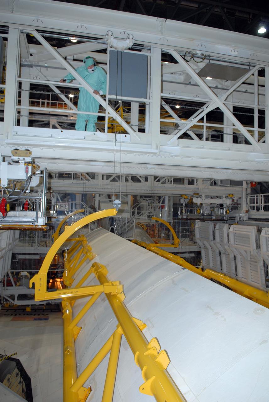
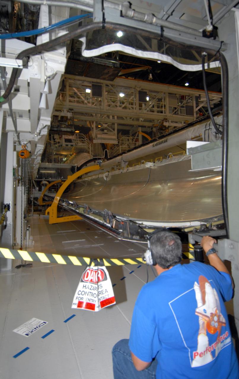
This photograph was taken during the final assembly operation of the Saturn V launch vehicle for the Apollo 4 (SA 501) mission. The instrument unit (IU) was mated atop the S-IC/S-II assembly in the Vehicle Assembly Building high bay at the Kennedy Space Center. The Apollo 4 mission was the first launch of the Saturn V launch vehicle. Objectives of the unmanned Apollo 4 test flight were to obtain flight information on launch vehicle and spacecraft structural integrity and compatibility, flight loads, stage separation, and subsystems operation including testing of restart of the S-IVB stage, and to evaluate the Apollo command module heat shield. The Apollo 4 was launched on November 9, 1967 from KSC.
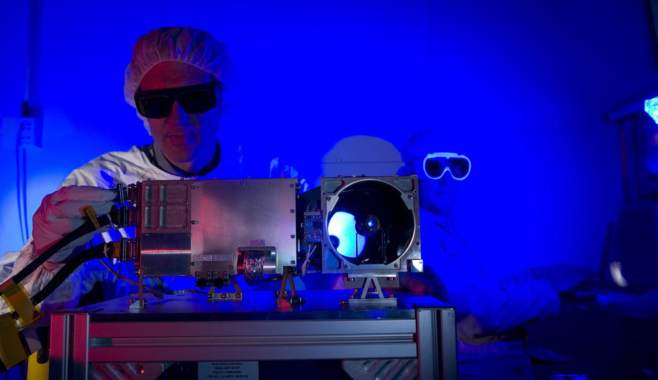
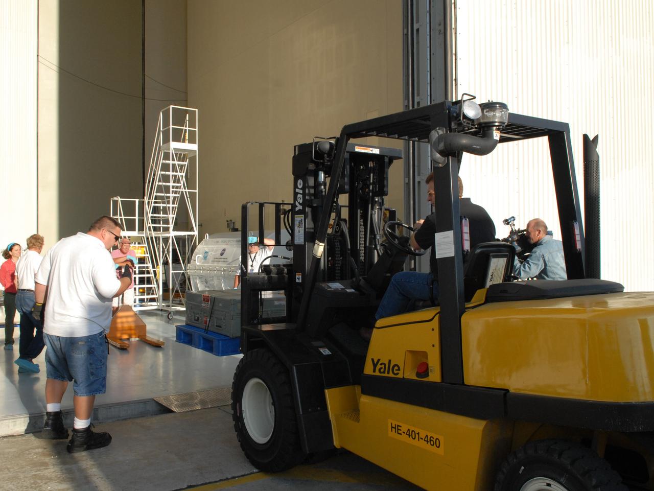
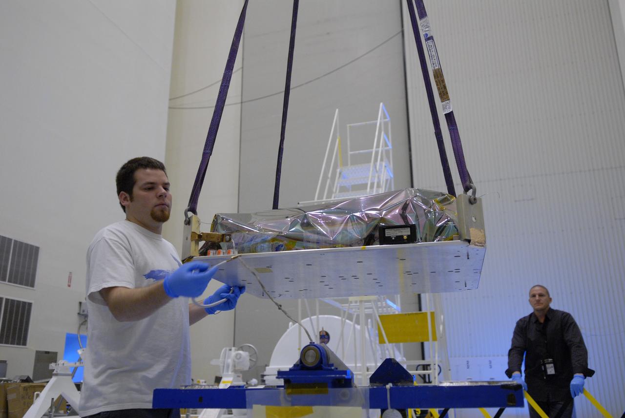
Researchers prepare for a test of the Chemistry and Camera ChemCam instrument that will fly on NASA Mars Science Laboratory mission; researchers are preparing the instrument mast unit for a laser firing test.
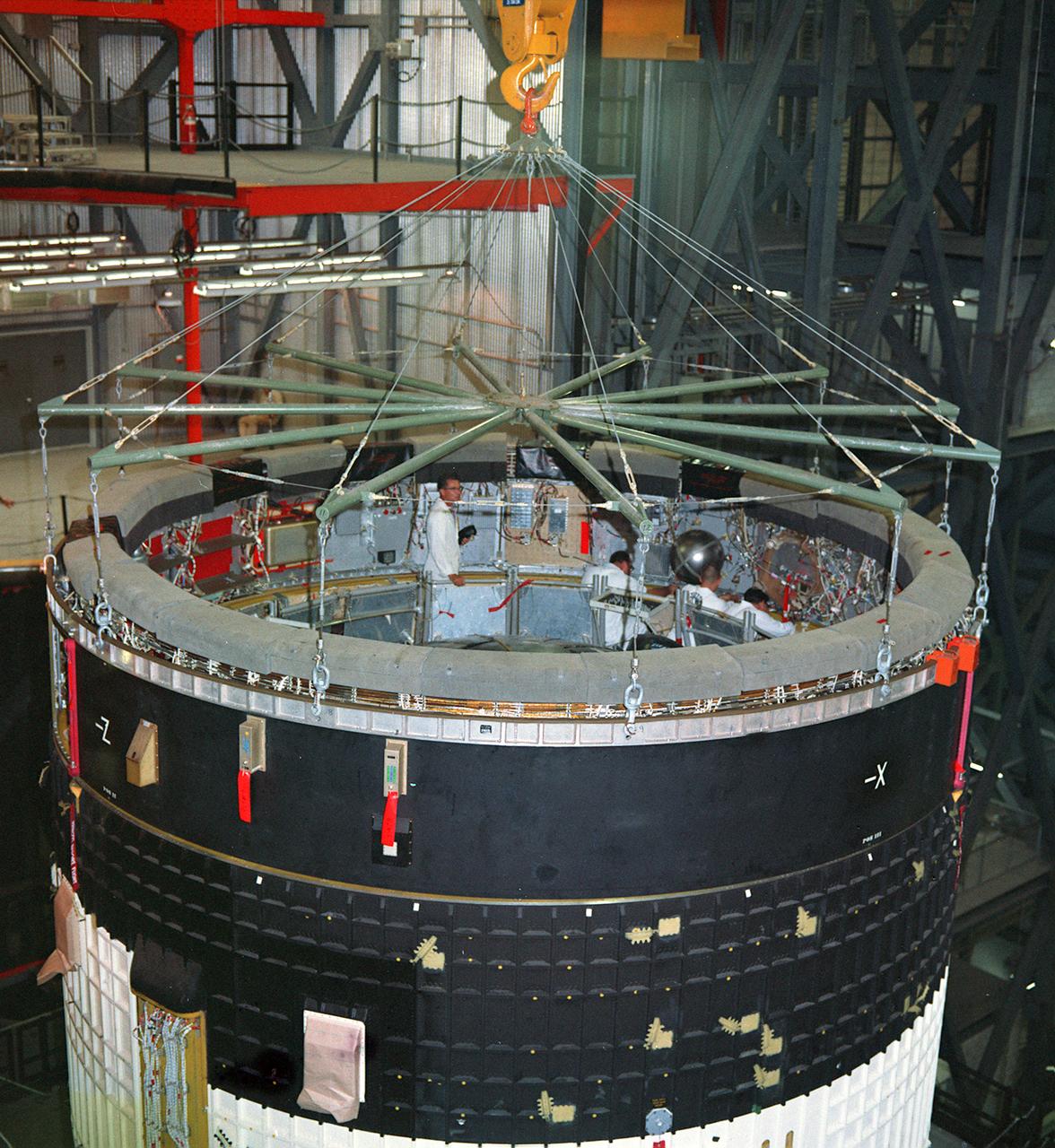
This photograph was taken during the final assembly operation of the Saturn V launch vehicle for the Apollo 4 (SA 501) mission. The instrument unit (IU) was hoisted to be mated to the S-IC/S-II assembly in the Vehicle Assembly Building high bay at the Kennedy Space Center. The Apollo 4 mission was the first launch of the Saturn V launch vehicle. Objectives of the unmanned Apollo 4 test flight were to obtain flight information on launch vehicle and spacecraft structural integrity and compatibility, flight loads, stage separation, and subsystems operation including testing of restart of the S-IVB stage, and to evaluate the Apollo command module heat shield. The Apollo 4 was launched on November 9, 1967 from KSC.
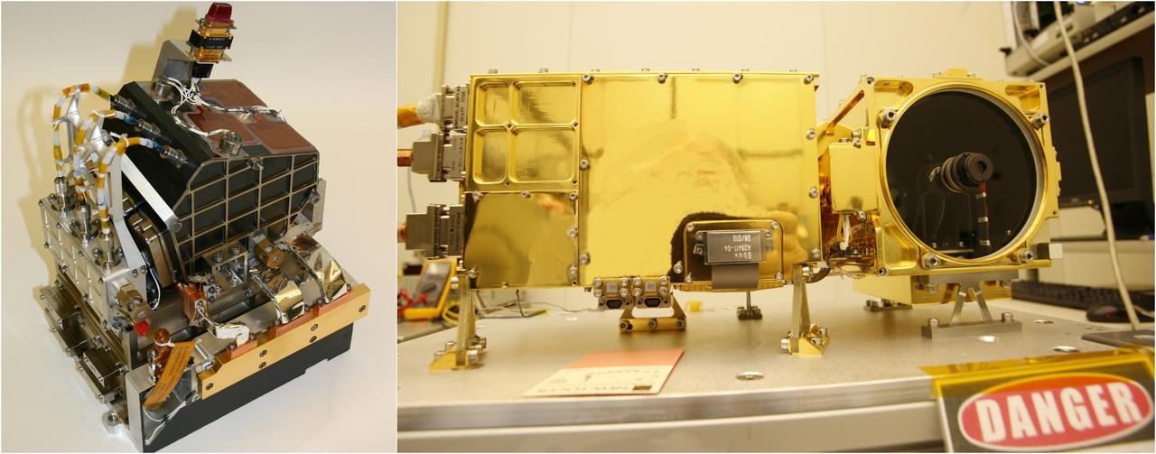
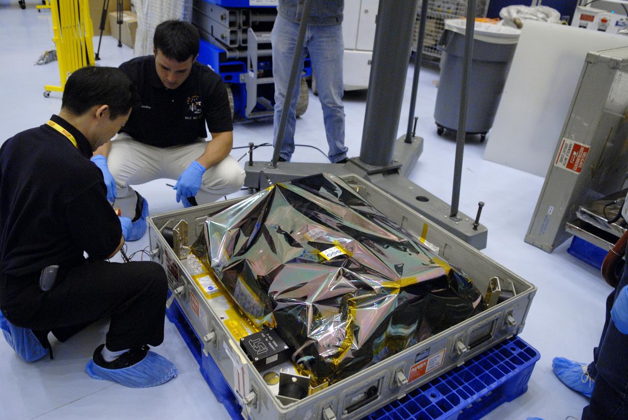
The two main parts of the ChemCam laser instrument for NASA Mars Science Laboratory mission are shown in this combined image.
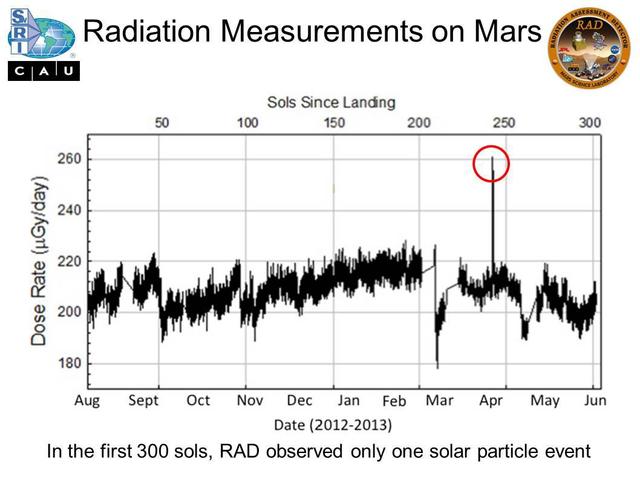
Micrograys are unit of measurement for absorbed radiation dose. The vertical axis is in micrograys per day. The RAD instrument on NASA Curiosity Mars rover monitors the natural radiation environment at the surface of Mars.
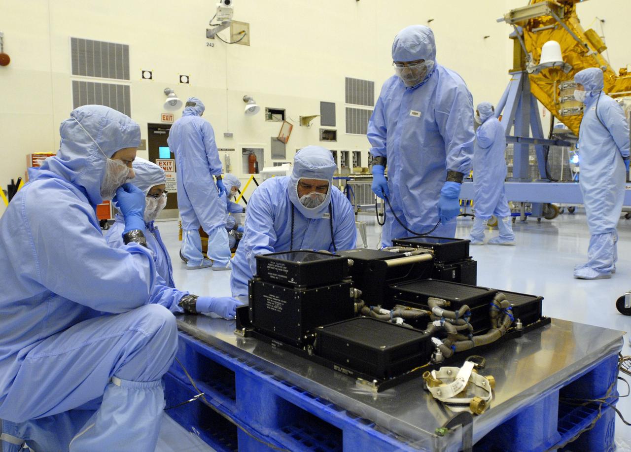
This image shows four Wet Chemistry Laboratory units, part of the Microscopy, Electrochemistry, and Conductivity Analyzer MECA instrument on board NASA Phoenix Mars Lander. This image was taken before Phoenix launch on August 4, 2007.
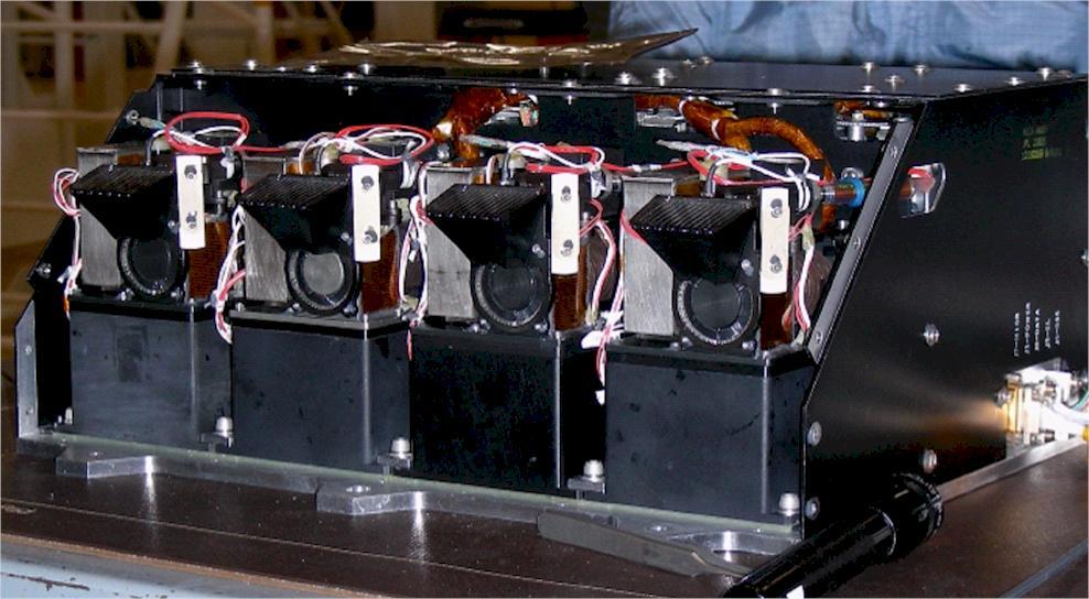
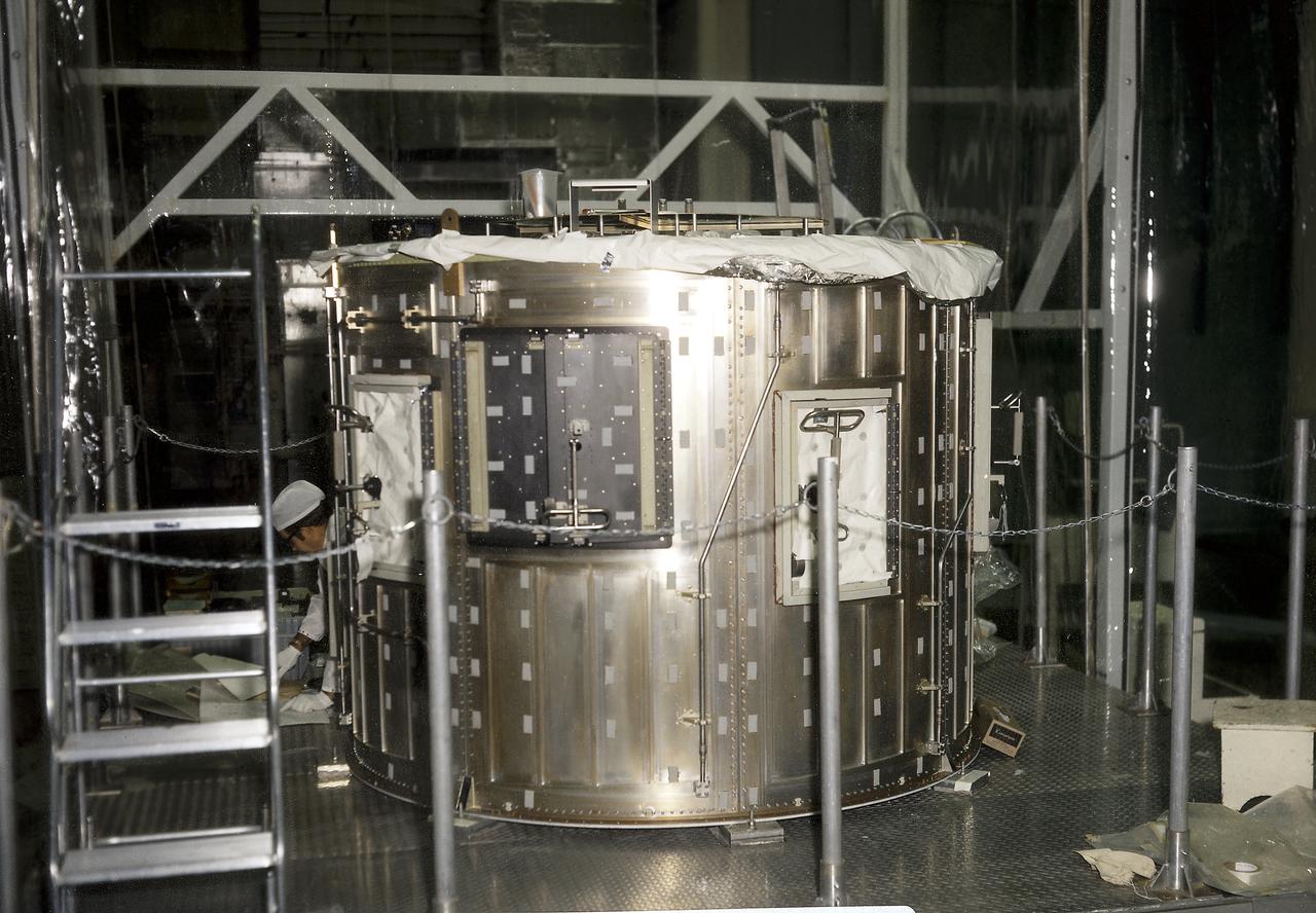
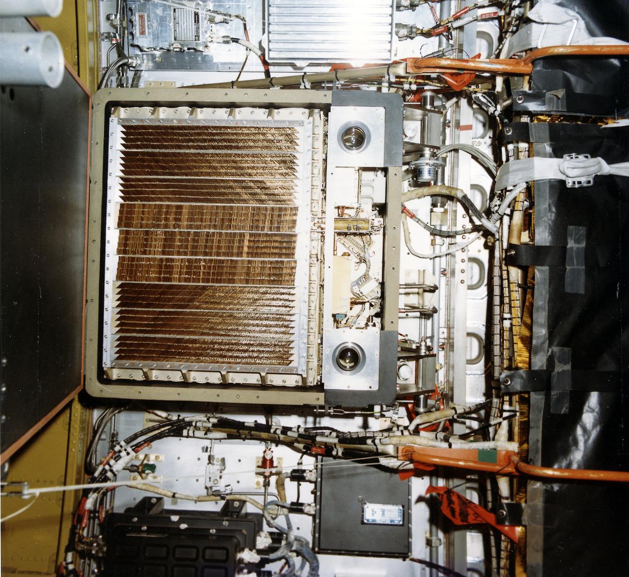
The Apollo Telescope Mount (ATM) was designed and developed by the Marshall Space Flight Center (MSFC) and served as the primary scientific instrument unit aboard Skylab (1973-1979). The ATM consisted of eight scientific instruments as well as a number of smaller experiments. This image is of the ATM thermal unit being tested in MSFC's building 4619. The thermal unit consisted of an active fluid-cooling system of water and methanol that was circulated to radiators on the outside of the canister. The thermal unit provided temperature stability to the ultrahigh resolution optical instruments that were part of the ATM.
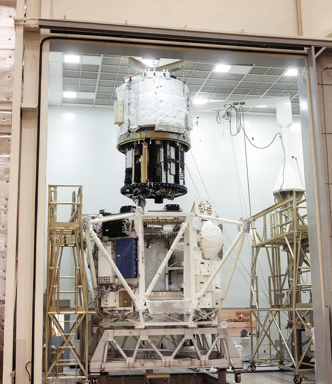
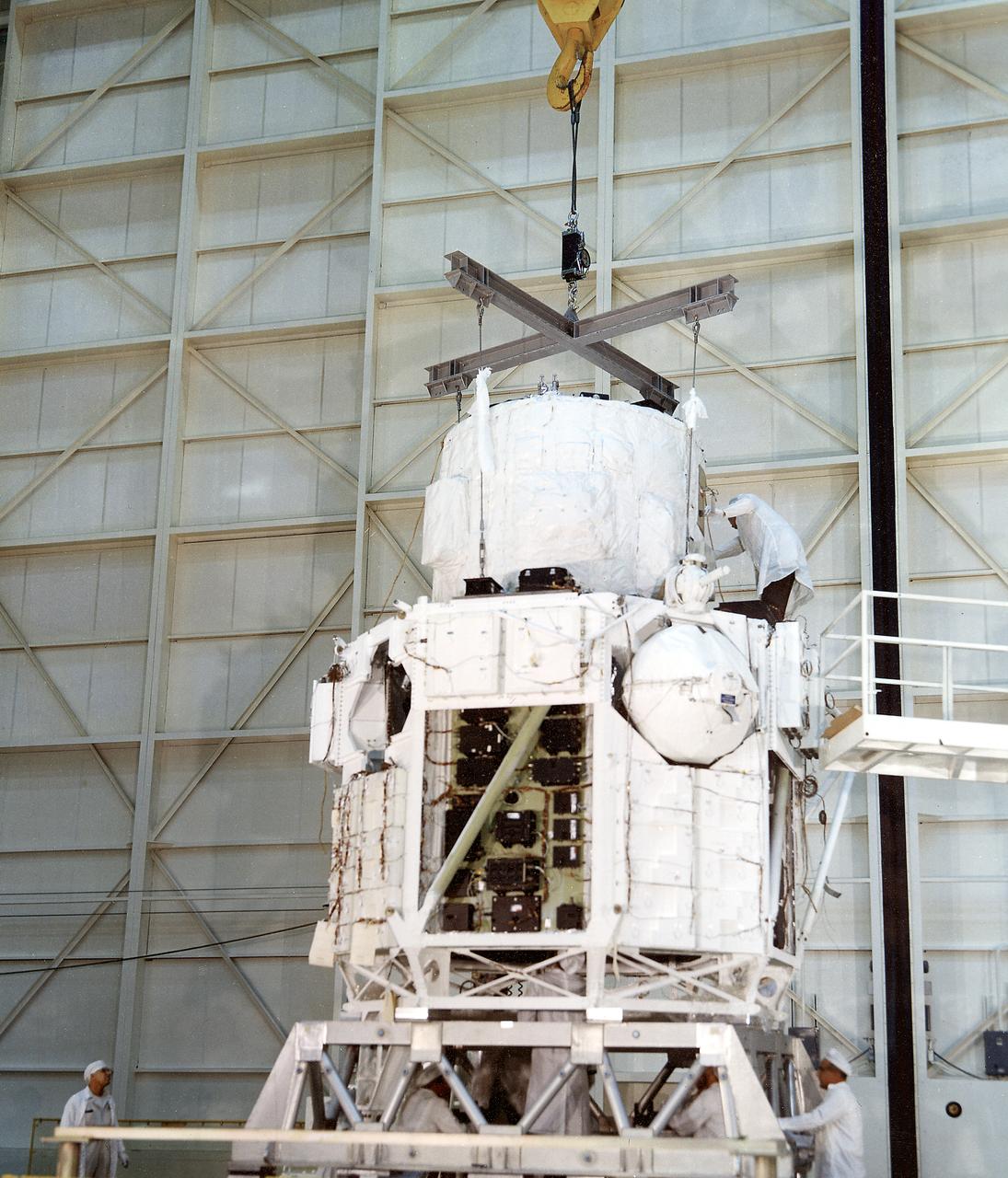
The Apollo Telescope Mount (ATM) was designed and developed by the Marshall Space Flight Center and served as the primary scientific instrument unit aboard Skylab (1973-1979). This photograph shows the spar unit, which housed major solar instruments, being lowered into the rack, the outer octagonal complex frame of the ATM flight unit.
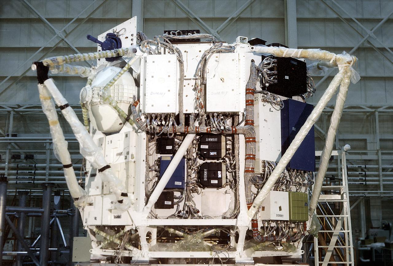
The Apollo Telescope Mount (ATM) was designed and developed by the Marshall Space Flight Center and served as the primary scientific instrument unit aboard Skylab (1973-1979). The ATM consisted of eight scientific instruments as well as a number of smaller experiments. This is a photograph of the assembly of an ATM flight unit rack. The flight unit rack was an octagonal shaped complex outer frame that housed the canister containing the solar instruments.
The Apollo Telescope Mount (ATM) was designed and developed by the Marshall Space Flight Center and served as the primary scientific instrument unit aboard Skylab (1973-1979). The ATM consisted of eight scientific instruments as well as a number of smaller experiments. This is a photograph of the assembly of an ATM flight unit rack. The flight unit rack was an octagonal shaped complex outer frame that housed the canister containing the solar instruments.

The Apollo Telescope Mount (ATM) was designed and developed by the Marshall Space Flight Center and served as the primary scientific instrument unit aboard Skylab (1973-1979). The ATM consisted of eight scientific instruments as well as a number of smaller experiments. This is a photograph of the assembly of an ATM flight unit rack. The flight unit rack was an octagonal shaped complex outer frame that housed the canister containing the solar instruments.
The Apollo Telescope Mount (ATM) was designed and developed by the Marshall Space Flight Center (MSFC) and served as the primary scientific instrument unit aboard Skylab (1973-1979). The ATM consisted of eight scientific instruments as well as a number of smaller experiments. This image is of the ATM flight unit sun end canister in MSFC's building 4755.
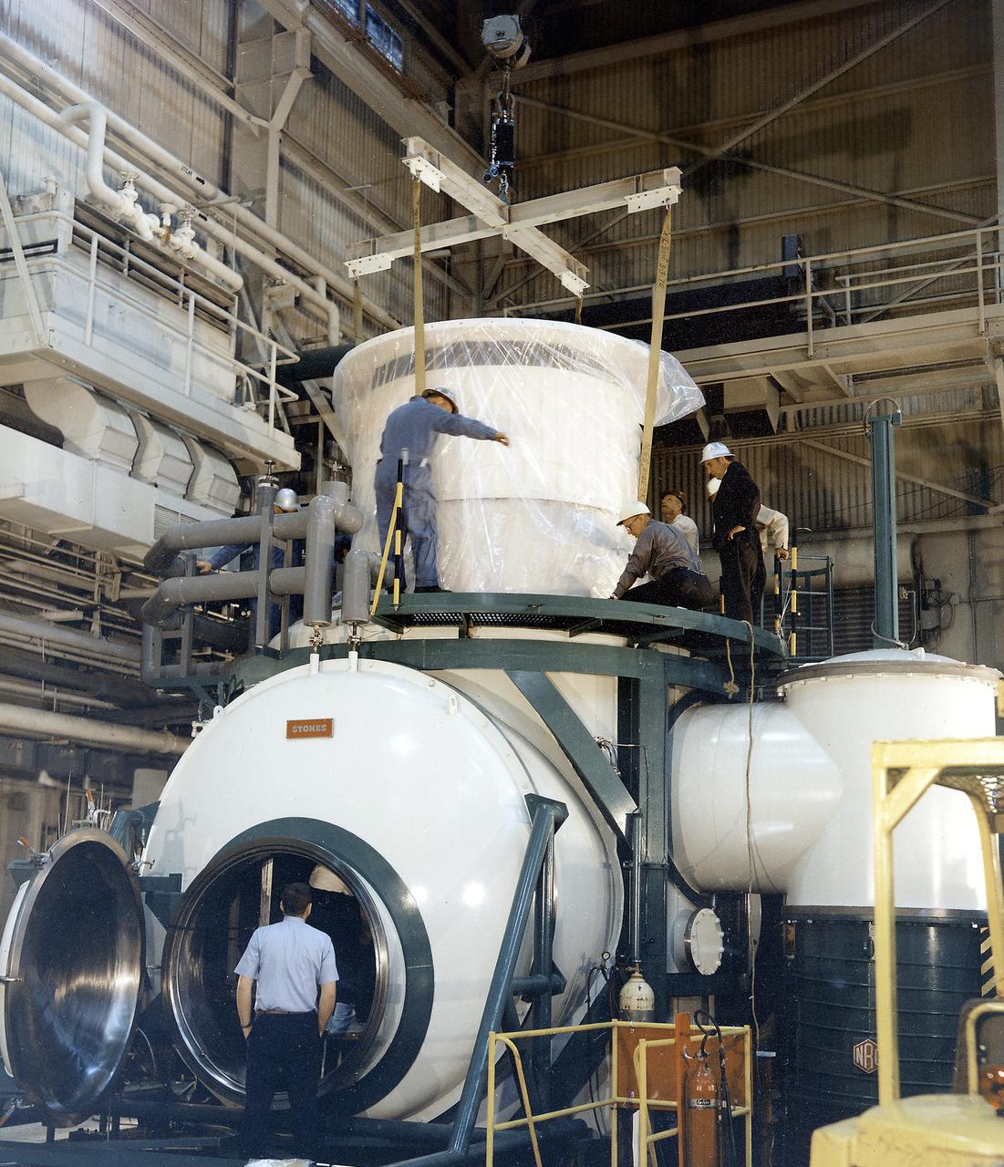
The Apollo Telescope Mount (ATM) was designed and developed by the Marshall Space Flight Center (MSFC) and served as the primary scientific instrument unit aboard Skylab (1973-1979). The ATM consisted of eight scientific instruments as well as a number of smaller experiments. In this image, the thermal unit, that controlled the temperature stability of the ATM, is being installed into a vacuum chamber.
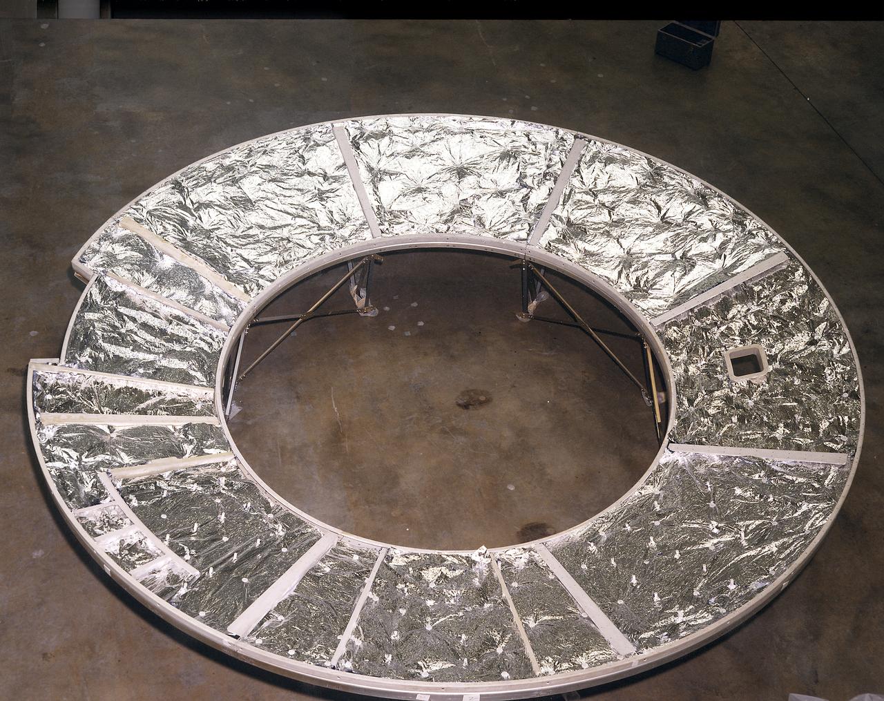
The Apollo Telescope Mount (ATM) was designed and constructed at the Marshall Space Flight Center and served as the primary scientific instrument unit aboard Skylab. The ATM consisted of eight scientific instruments as well as a number of smaller experiments. This photograph shows the flight unit solar shield for the ATM that formed the base for the rack, a complex frame, and the canister that contained the instruments.
The Apollo Telescope Mount (ATM) was designed and developed by the Marshall Space Flight Center and served as the primary scientific instrument unit aboard Skylab (1973-1979). The ATM consisted of eight scientific instruments as well as a number of smaller experiments. In this image, the ATM canister, housing the solar instruments, is mated to the thermal rack that provided thermal stability.
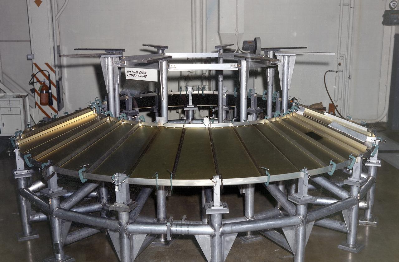
The Apollo Telescope Mount (ATM) was designed and developed by the Marshall Space Flight Center and served as the primary scientific instrument unit aboard Skylab (1973-1979). The ATM consisted of eight scientific instruments as well as a number of smaller experiments. One scientific instrument was the ATM solar shield that formed the base for the rack/frame instrument and the instrument canister. The solar shield contained aperture doors for each instrument to protect against solar radiation and space contamination.
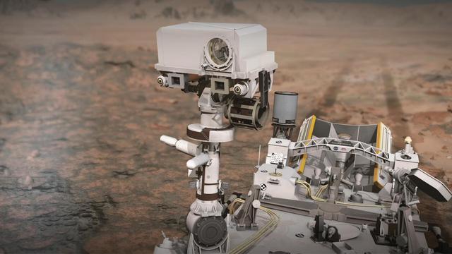
This narrated animation shows NASA's Perseverance rover on Mars and how the rover's SuperCam laser instrument works. SuperCam is led by Los Alamos National Laboratory in New Mexico, where the instrument's Body Unit was developed. That part of the instrument includes several spectrometers, control electronics and software. The Mast Unit was developed and built by several laboratories of the CNRS (French research center) and French universities under the contracting authority of CNES (French space agency). Calibration targets on the rover deck are provided by Spain's University of Valladolid. Animation available at https://photojournal.jpl.nasa.gov/catalog/PIA24426
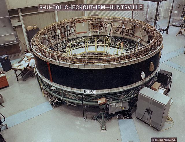
A technician checks the systems of the Saturn V instrument unit in a test facility in Huntsville. This instrument unit was flown aboard Apollo 4 on November 7, 1967, which was the first test flight of the Saturn V. The towering 363-foot Saturn V was a multi-stage, multi-engine launch vehicle standing taller than the Statue of Liberty. Altogether, the Saturn V engines produced as much power as 85 Hoover Dams.
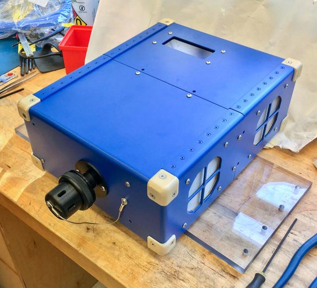
jsc2020e004941 (2/7/2020) --- A preflight view of the Airborne Particulate Monitor (APM) engineering unit. APM technology has applications in environmental monitoring and air pollution studies on Earth. Its combination of two instruments into one box offers a wider range of particle size measurement than other commercially available instruments.
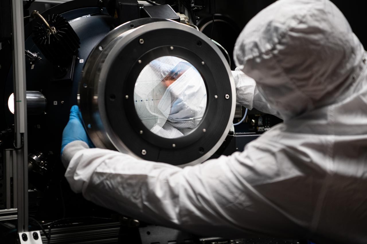
Senior Engineer George Hilton adjusts a polarizer during GSE testing of the Ocean Color Instrument Engineering Test Unit at NASA Goddard Space Flight Center on December 10th, 2020. Photo Credit: (NASA/Denny Henry)
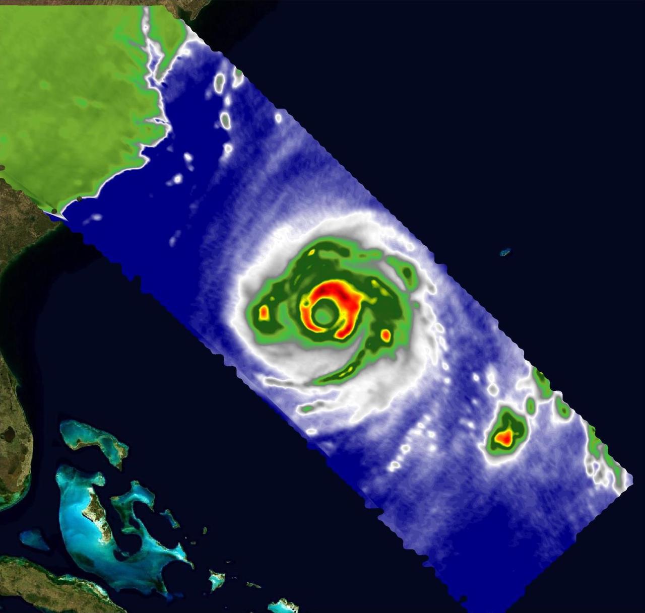
A pair of weather instruments built at NASA's Jet Propulsion Laboratory in Southern California captured images of Hurricane Franklin as the Category 4 storm moved off the East Coast of the United States on Aug. 29, 2023. COWVR (short for Compact Ocean Wind Vector Radiometer) and TEMPEST (Temporal Experiment for Storms and Tropical Systems) observe the planet's atmosphere and surface from aboard the International Space Station, which passed in low Earth orbit over the storm at about 9:58 a.m. EDT. This image combines microwave emissions measurements from both COWVR and TEMPEST. White sections indicate the presence of clouds. Green portions indicate rain. Yellow, red, and black indicate where air and water vapor were moving most vigorously. Franklin's center is seen about 700 miles (1,127 kilometers) east of Jacksonville, Florida, over the Atlantic Ocean. https://photojournal.jpl.nasa.gov/catalog/PIA25870
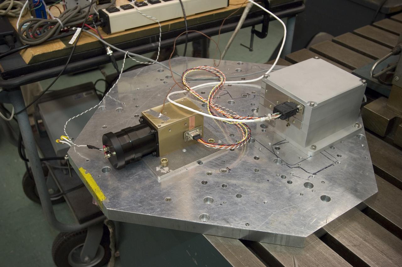
Lunar CRater Observation and Sensing Satellite (LCROSS) and P.I. at NASA Ames Research Center - close up of Total Luminance Photometer: Metal shake table close up. Shows two units bolted on. The left one is the lens, sensor electronics and photometer sensor. The right is the digital electronics unit for the instrument. The two units, along with their cabling is one of the LCROSS science insruments.
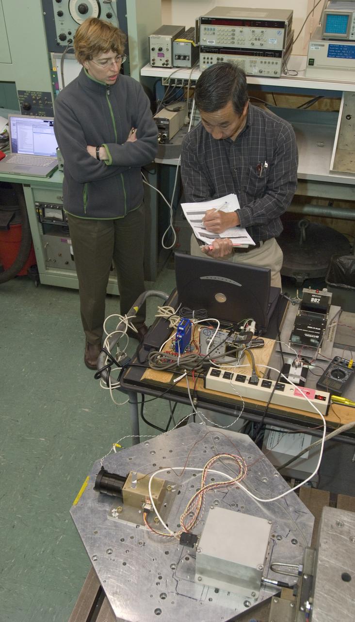
Lunar CRater Observation and Sensing Satellite (LCROSS) and P.I. at NASA Ames Research Center - Total Luminance Photometer shake test in N-244 (EEL) : Metal shake table close up. Shows two units bolted on. The left one is the lens, sensor electronics and photometer sensor. The right is the digital electronics unit for the instrument. The two units, along with their cabling is one of the LCROSS science insruments.
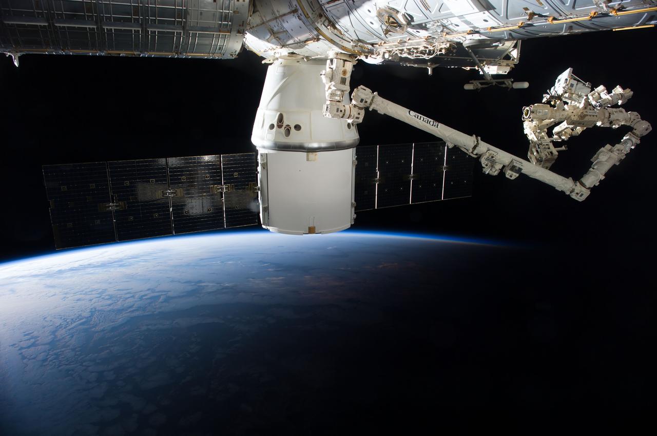
iss041e047260 (9/29/2014) --- A view of the removal of the RapidScat Nadir Adapter from the SpaceX-4 Dragon trunk and installation of the adapter onto the Columbus Exposed Facility Unit (EFU). ISS-RapidScat is a space-based scatterometer that replaces the inoperable SeaWinds payload aboard the QuickSCAT satellite. Scatterometers are radar instruments that measure wind speed and direction over the ocean, and are useful for weather forecasting, hurricane monitoring, and observations of large-scale climate phenomena such as El Niño. The ISS RapidScat instrument enhances measurements from other international scatterometers by cross-checking their data, and demonstrates a unique way to replace an instrument aboard an aging satellite. External Caption
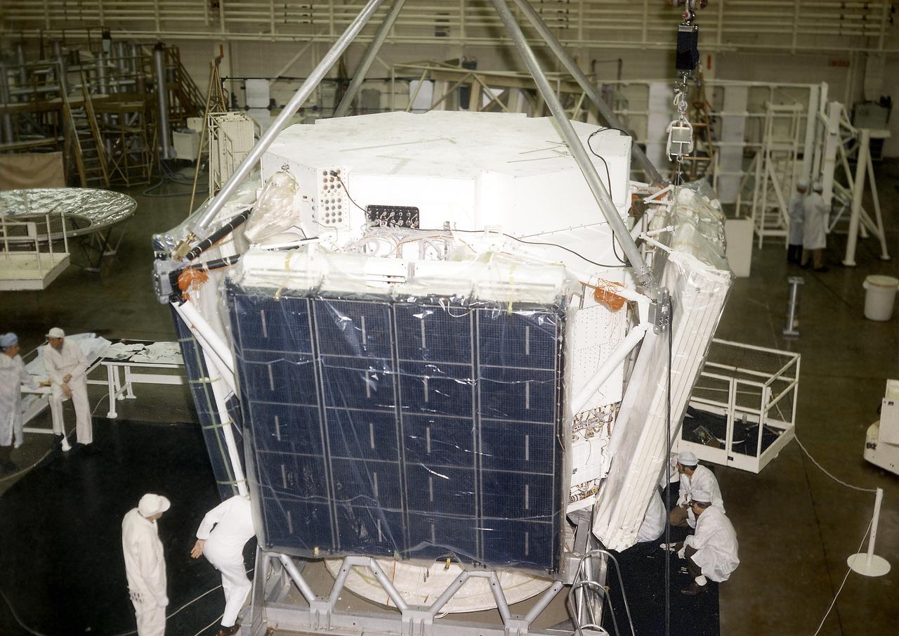
The Apollo Telescope Mount (ATM) was designed and developed by the Marshall Space Flight Center and served as the primary scientific instrument unit aboard Skylab (1973-1979). The ATM consisted of eight scientific instruments as well as a number of smaller experiments. In this image, the set of four large solar cell arrays, which could produce up to as much as 1.1 kilowatts of electric power, are being installed on an ATM prototype.
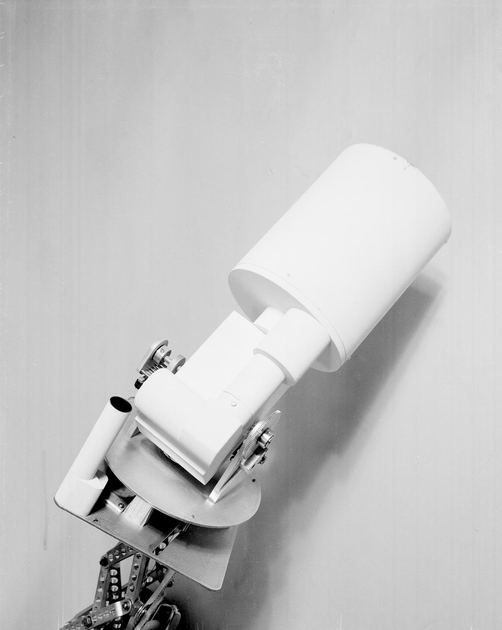
The Apollo Telescope Mount (ATM), designed and developed by the Marshall Space Flight Center, served as the primary scientific instrument unit aboard the Skylab. The ATM contained eight complex astronomical instruments designed to observe the Sun over a wide spectrum from visible light to x-rays. This photo depicts a mockup of the ATM contamination monitor camera and photometer.
The Apollo Telescope Mount (ATM), designed and developed by the Marshall Space Flight Center, served as the primary scientific instrument unit aboard the Skylab. The ATM contained eight complex astronomical instruments designed to observe the Sun over a wide spectrum from visible light to x-rays. This photo depicts a side view is of a fully extended ATM contamination monitor mockup.
This photograph shows Skylab's Galactic X-Ray Mapping facility (S150), an astrophysics and space sciences investigation. An objective of this experiment was to extend the search for the origin of galactic x-rays beyond the sensitivity possible with short flights of small research rockets. This was accomplished by placing a large-area, soft x-ray detector in orbit to collect data for a much longer time. The S150 instrument was not in Skylab but in the instrument unit of the second stage of the Skylab-3 Saturn IB rocket.
The Apollo Telescope Mount (ATM), designed and developed by the Marshall Space Flight Center, served as the primary scientific instrument unit aboard the Skylab. The ATM contained eight complex astronomical instruments designed to observe the Sun over a wide spectrum from visible light to x-rays. This angle view is of an ATM contamination monitor meter mockup.
This photograph shows Skylab's Extreme Ultraviolet (XUV) Spectroheliograph during an acceptance test and checkout procedures in April 1971. The unit was an Apollo Telescope Mount (ATM) instrument designed to sequentially photograph the solar chromosphere and corona in selected ultraviolet wavelengths. The instrument also obtained information about composition, temperature, energy conversion and transfer, and plasma processes of the chromosphere and lower corona. The Marshall Space Flight Center had program management responsibility for the development of Skylab hardware and experiments.
The Apollo Telescope Mount (ATM), designed and developed by the Marshall Space Flight Center, served as the primary scientific instrument unit aboard the Skylab. The ATM contained eight complex astronomical instruments designed to observe the Sun over a wide spectrum from visible light to x-rays. This photo of the ATM contamination monitor mockup offers an extended view of the sunshield interior.
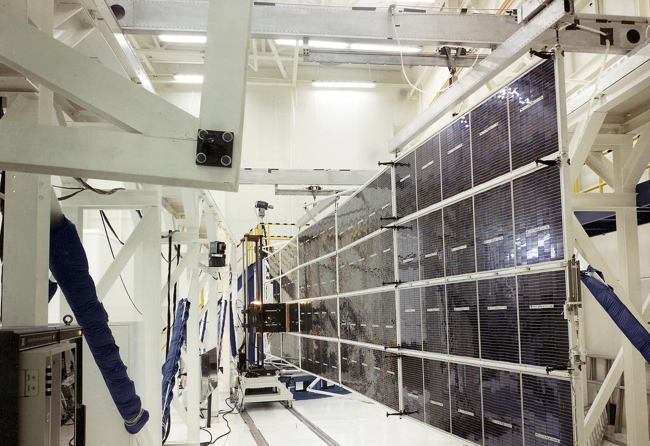
The Apollo Telescope Mount (ATM), one of four major components comprising Skylab, was designed and developed by the Marshall Space Flight Center. Power to operate the ATM's instruments and experiments was collected by four solar arrays, capable of producing up to 1.1 kilowatts of electricity. This is a photograph of the ATM Solar Array flight unit deployed for illumination testing.

STS005-04-146 (11-16 Nov. 1982) --- Astronaut William B. Lenoir, STS-5 mission specialists, checks his vision using DIOPTER measuring device on middeck in front of Development Flight Instrument (DFI) unit. Photo credit: NASA
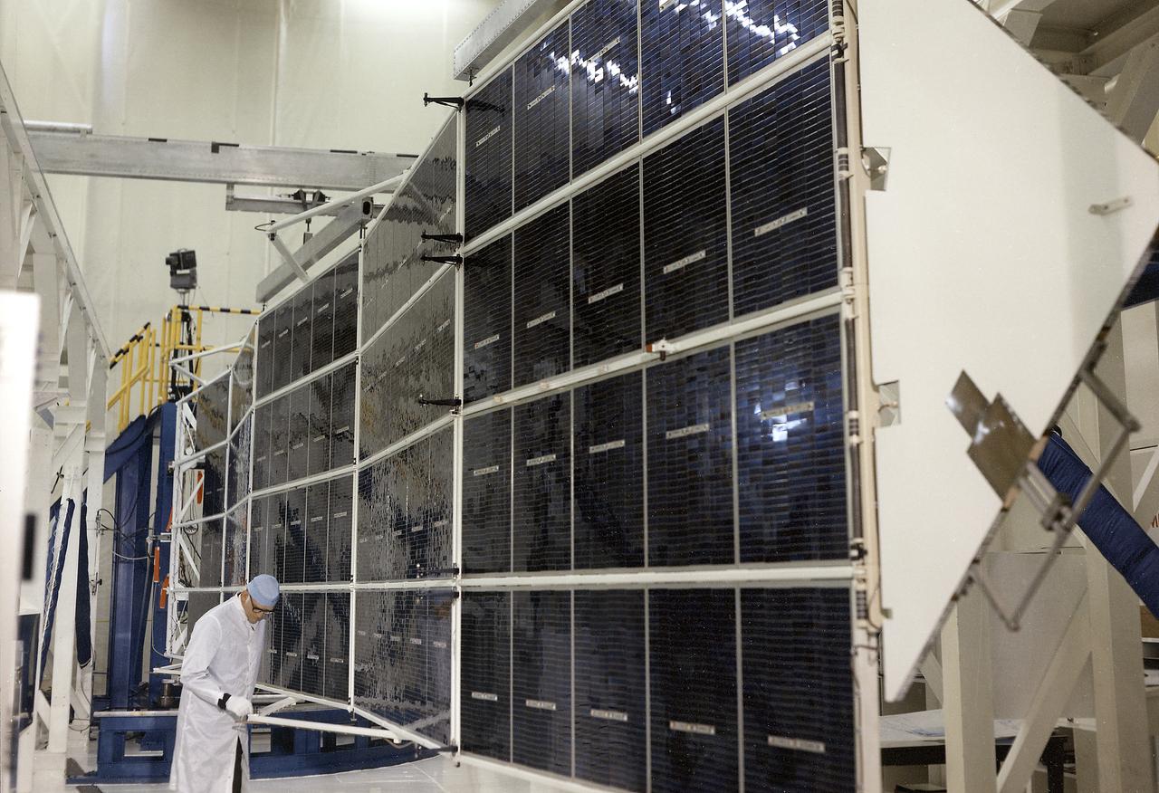
The Apollo Telescope Mount (ATM), one of four major components comprising Skylab, was designed and developed by the Marshall Space Flight Center. Power to operate the ATM's instruments and experiments was collected by four solar arrays, capable of producing up to 1.1 kilowatts of electricity. This is a photograph of the ATM Solar Array flight unit 1 in the deployed position.
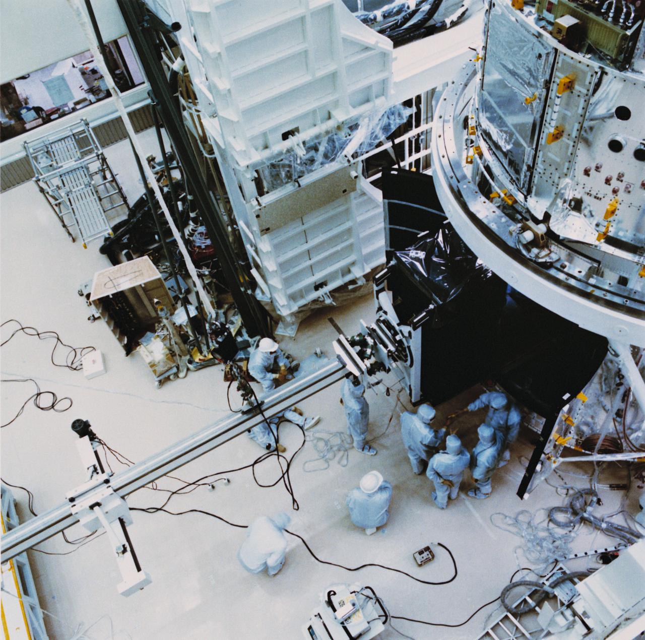
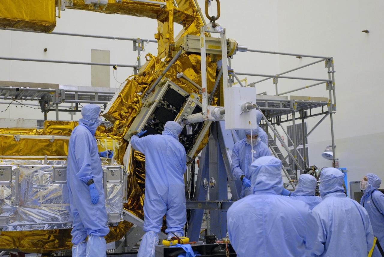
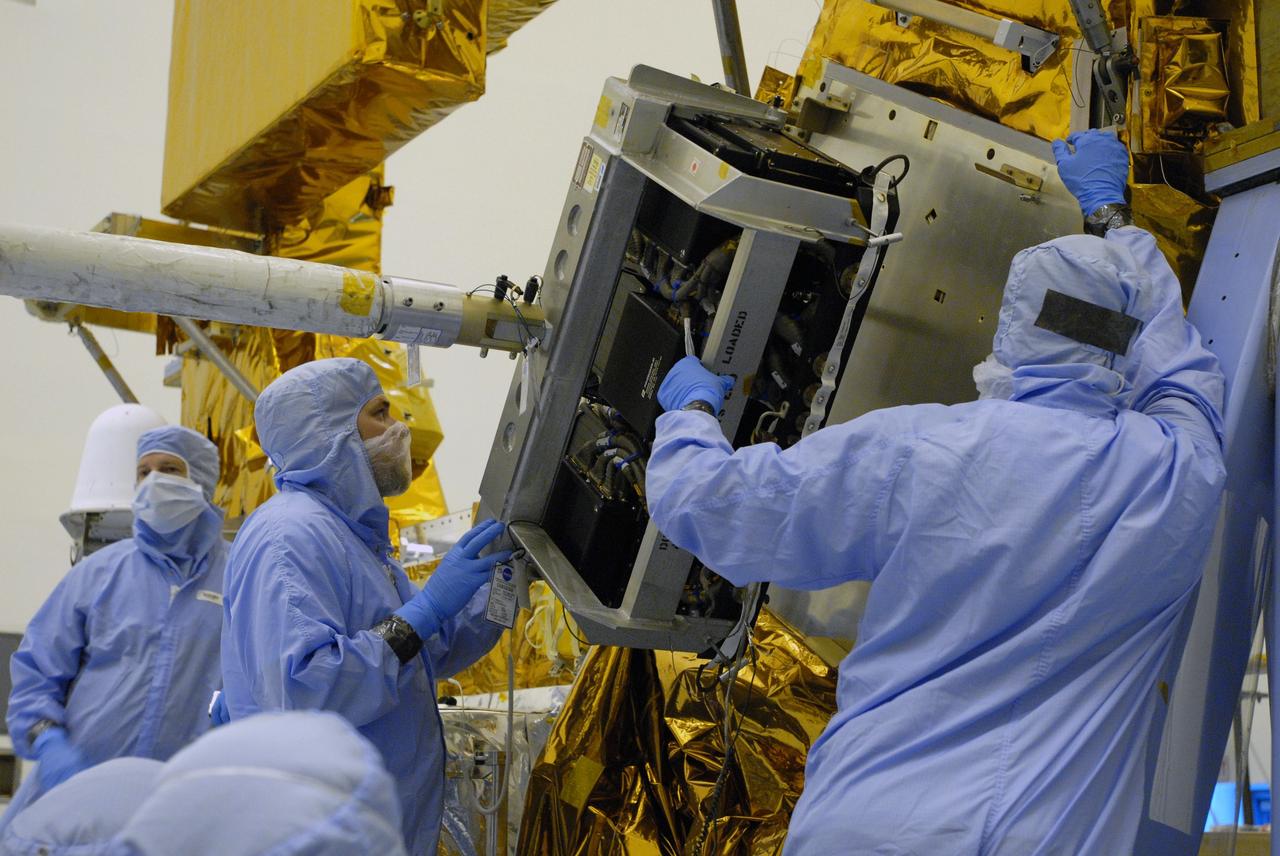
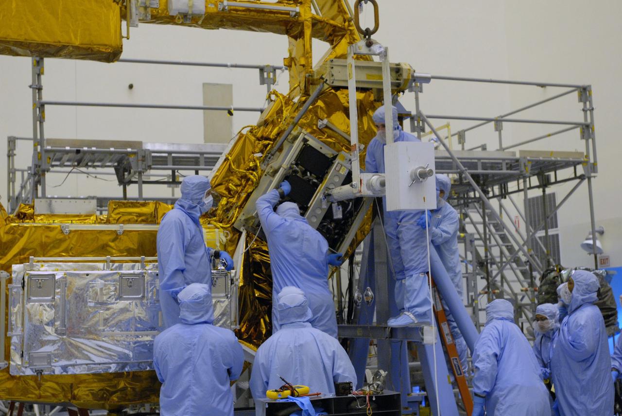
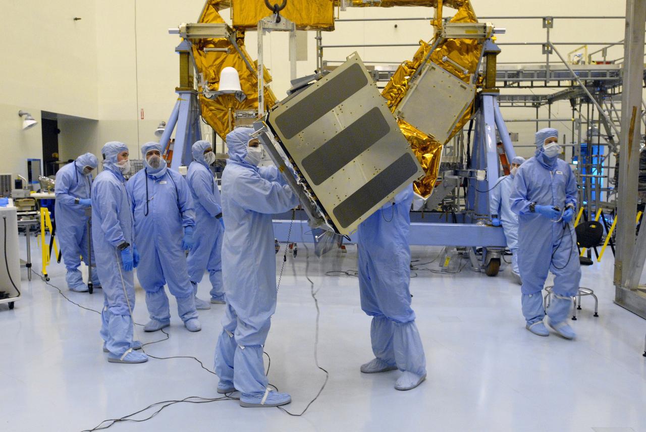
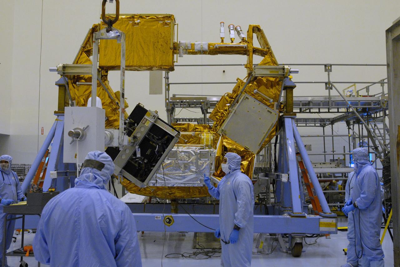
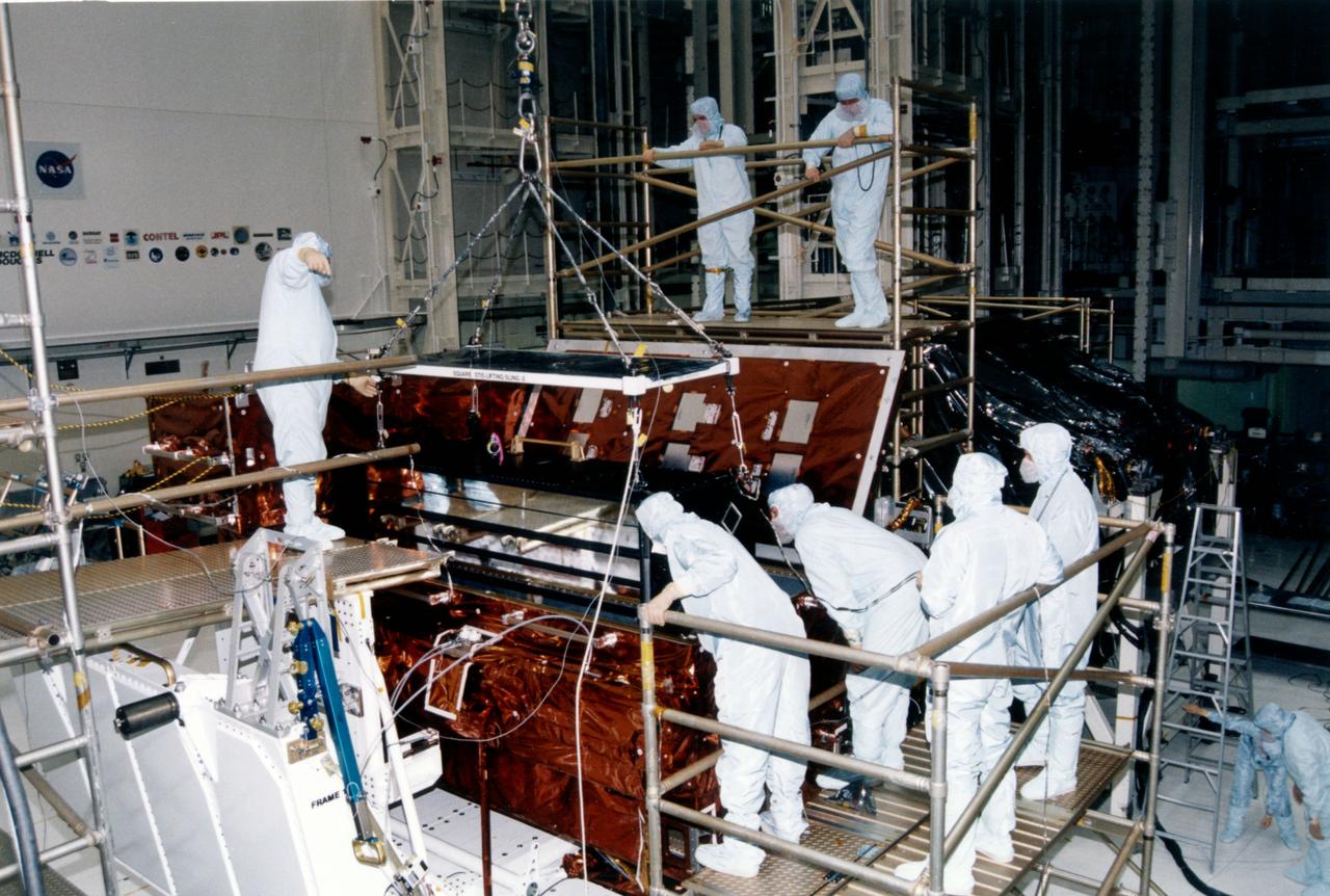
A mechanical arm positions the axial scientific instrument (SI) module (orbital replacement unit (ORU)) just outside the open doors of the Hubble Space Telescope (HST) Support System Module (SSM) as clean-suited technicians oversee the process. HST assembly is being completed at the Lockheed Facility in Sunnyvale, California.
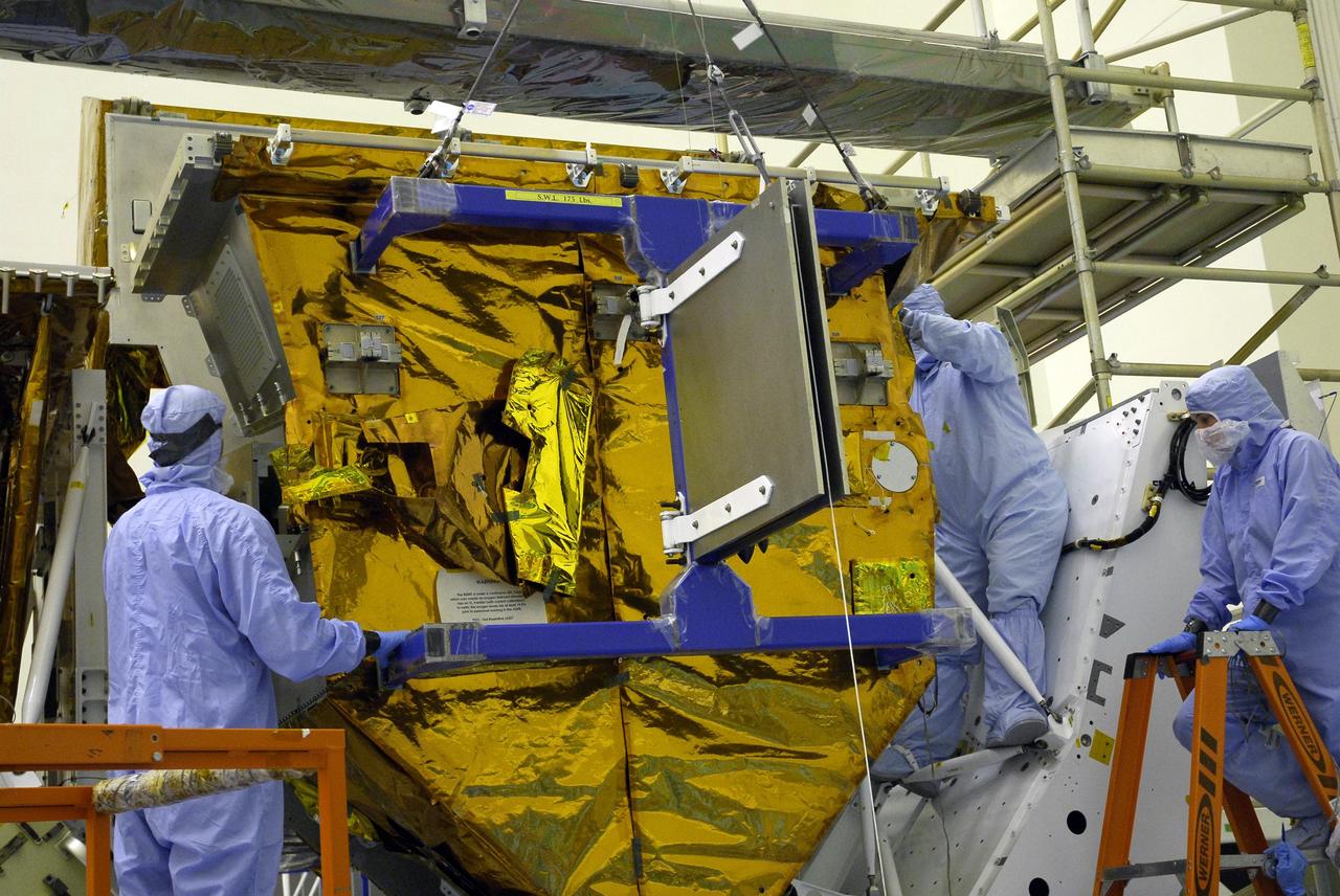
CAPE CANAVERAL, Fla. – In the Payload Hazardous Servicing Facility at NASA's Kennedy Space Center in Florida, technicians help with the installation of the Science Instrument Command and Data Handling Unit, or SIC&DH, on the Multi-Use Lightweight Equipment Carrier. The SIC&DH will be installed on the Hubble Space Telescope during space shuttle Atlantis' STS-125 mission. This unit will replace the one that suffered a failure aboard the orbiting telescope on Sept. 27, 2008. Atlantis is targeted for launch on May 12. Photo credit: NASA/Dimitri Gerondidakis
CAPE CANAVERAL, Fla. – In the Payload Hazardous Servicing Facility at NASA's Kennedy Space Center in Florida, technicians look over the Science Instrument Command and Data Handling Unit, or SIC&DH, installed on the Multi-Use Lightweight Equipment Carrier. The SIC&DH will be installed on the Hubble Space Telescope during space shuttle Atlantis' STS-125 mission. This unit will replace the one that suffered a failure aboard the orbiting telescope on Sept. 27, 2008. Atlantis is targeted for launch on May 12. Photo credit: NASA/Dimitri Gerondidakis
CAPE CANAVERAL, Fla. – In the Payload Hazardous Servicing Facility at NASA's Kennedy Space Center in Florida, technicians help with the installation of the Science Instrument Command and Data Handling Unit, or SIC&DH, on the Multi-Use Lightweight Equipment Carrier. The SIC&DH will be installed on the Hubble Space Telescope during space shuttle Atlantis' STS-125 mission. This unit will replace the one that suffered a failure aboard the orbiting telescope on Sept. 27, 2008. Atlantis is targeted for launch on May 12. Photo credit: NASA/Dimitri Gerondidakis
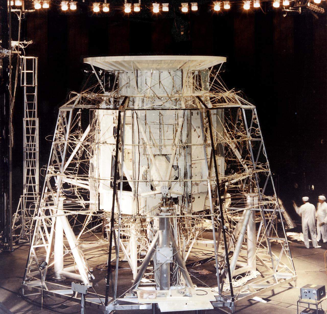
The Apollo Telescope Mount (ATM), designed and developed by the Marshall Space Flight Center, was one of four major components comprising the Skylab (1973-1979). The ATM housed the first manned scientific telescope in space. This photograph is of the ATM thermal systems unit undergoing testing in the Space Environment Simulation Laboratory of the Manned Spacecraft Center (MSC). The ATM thermal systems unit was used to control the temperatures of space instrument's subsystems during a mission. The MSC was renamed the Johnson Space Center (JSC) in early 1973.
CAPE CANAVERAL, Fla. – In the Payload Hazardous Servicing Facility at NASA's Kennedy Space Center in Florida, technicians check the Multi-Use Lightweight Equipment Carrier where the Science Instrument Command and Data Handling Unit, or SIC&DH, is being installed. The SIC&DH will be installed on the Hubble Space Telescope during space shuttle Atlantis' STS-125 mission. This unit will replace the one that suffered a failure aboard the orbiting telescope on Sept. 27, 2008. Atlantis is targeted for launch on May 12. Photo credit: NASA/Dimitri Gerondidakis
CAPE CANAVERAL, Fla. – In the Payload Hazardous Servicing Facility at NASA's Kennedy Space Center in Florida, the Science Instrument Command and Data Handling Unit, or SIC&DH, is moved toward the Multi-Use Lightweight Equipment Carrier in the background, where it will be installed. The SIC&DH will be installed on the Hubble Space Telescope during space shuttle Atlantis' STS-125 mission. This unit will replace the one that suffered a failure aboard the orbiting telescope on Sept. 27, 2008. Atlantis is targeted for launch on May 12. Photo credit: NASA/Dimitri Gerondidakis
CAPE CANAVERAL, Fla. – In the Payload Hazardous Servicing Facility at NASA's Kennedy Space Center in Florida, a technician prepares the Science Instrument Command and Data Handling Unit, or SIC&DH, for its move to the Multi-Use Lightweight Equipment Carrier in the facility. The SIC&DH will be installed on the Hubble Space Telescope during space shuttle Atlantis' STS-125 mission. This unit will replace the one that suffered a failure aboard the orbiting telescope on Sept. 27, 2008. Atlantis is targeted for launch on May 12. Photo credit: NASA/Dimitri Gerondidakis
CAPE CANAVERAL, Fla. – In the Payload Hazardous Servicing Facility at NASA's Kennedy Space Center in Florida, the Science Instrument Command and Data Handling Unit, or SIC&DH, is moved toward the Multi-Use Lightweight Equipment Carrier in the background, where it will be installed. The SIC&DH will be installed on the Hubble Space Telescope during space shuttle Atlantis' STS-125 mission. This unit will replace the one that suffered a failure aboard the orbiting telescope on Sept. 27, 2008. Atlantis is targeted for launch on May 12. Photo credit: NASA/Dimitri Gerondidakis
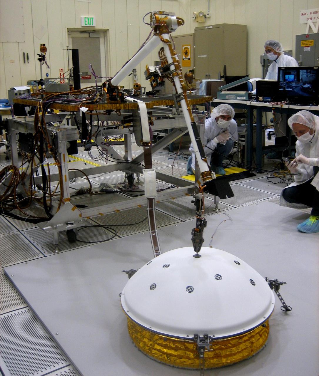
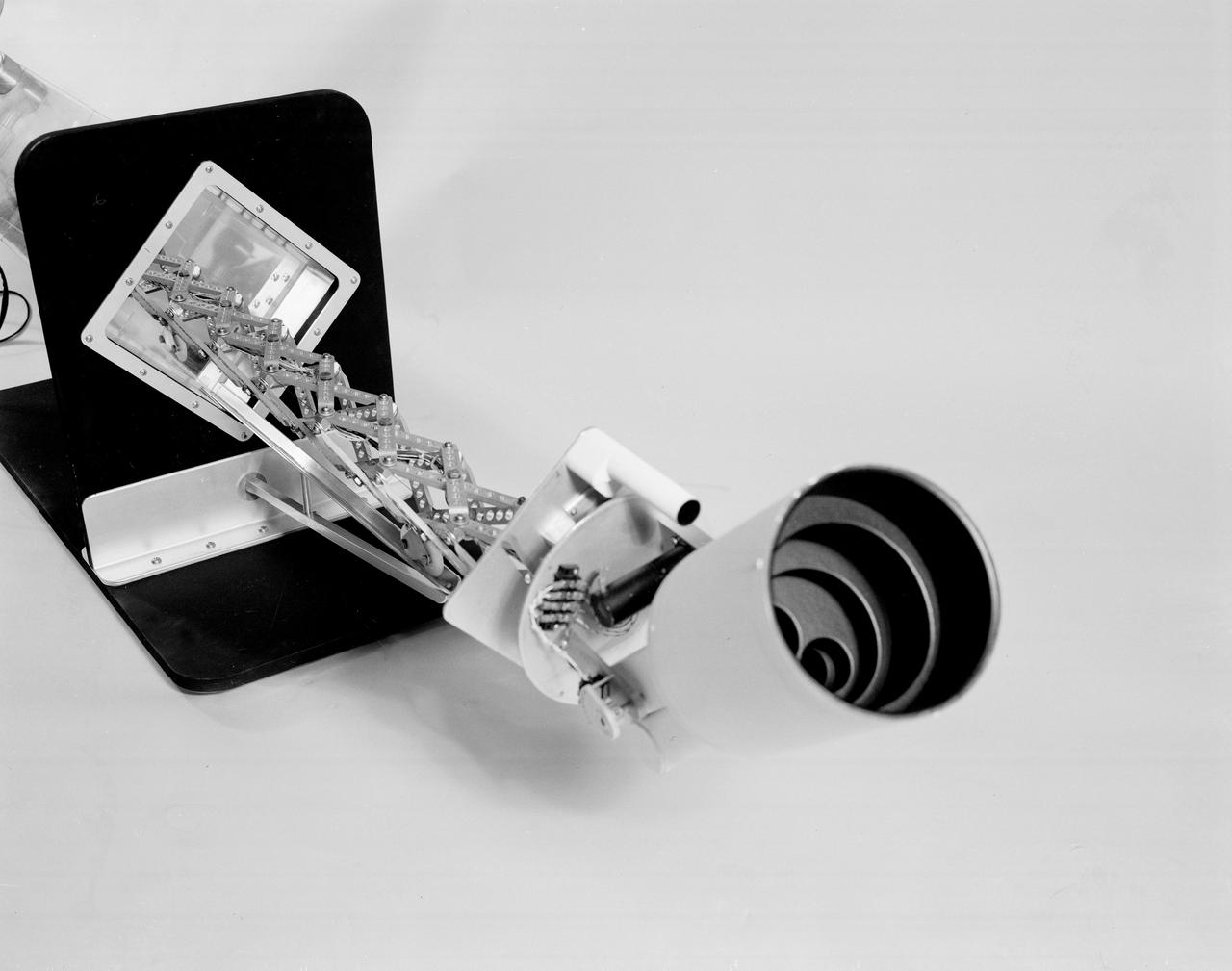
In the weeks after NASA's InSight mission reaches Mars in September 2016, the lander's arm will lift two key science instruments off the deck and place them onto the ground. This image shows testing of InSight's robotic arm inside a clean room at NASA's Jet Propulsion Laboratory, Pasadena, California, about two years before it will perform these tasks on Mars. InSight -- an acronym for Interior Exploration using Seismic Investigations, Geodesy and Heat Transport -- will launch in March 2016. It will study the interior of Mars to improve understanding of the processes that formed and shaped rocky planets, including Earth. One key instrument that the arm will deploy is the Seismic Experiment for Interior Structure, or SEIS. It is from France's national space agency (CNES), with components from Germany, Switzerland, the United Kingdom and the United States. In this scene, the arm has just deployed a test model of a protective covering for SEIS, the instrument's wind and thermal shield. The shield's purpose is to lessen disturbances that weather would cause to readings from the sensitive seismometer. Note: After thorough examination, NASA managers have decided to suspend the planned March 2016 launch of the Interior Exploration using Seismic Investigations Geodesy and Heat Transport (InSight) mission. The decision follows unsuccessful attempts to repair a leak in a section of the prime instrument in the science payload. http://photojournal.jpl.nasa.gov/catalog/PIA19144

The towns of Santa Claus, Ga., (top) and Santa Claus, Ind. (bottom), are shown in these two images from the Advanced Spaceborne Thermal Emission and Reflection Radiometer (ASTER) instrument on NASA's Terra satellite. They are the only two Santa Claus towns in the United States with post offices and zip codes, although there are 11 towns with this name in the United States. Santa Claus, Ga. is located in Toombs County, and has a population of 237. Santa Claus, Ind. is located in Spencer County, and has a population of 2,041. Its name was accepted by the United States Postal Service in 1856. The images were acquired on July 3, 2000 (top) and June 16, 2001 (bottom), respectively. http://photojournal.jpl.nasa.gov/catalog/PIA03891
CAPE CANAVERAL, Fla. – On Launch Pad 39A at NASA's Kennedy Space Center in Florida, space shuttle Atlantis' payload bay is filled with hardware for the STS-125 mission to service NASA's Hubble Space Telescope. From the bottom are the Flight Support System with the Soft Capture mechanism and Multi-Use Lightweight Equipment Carrier with the Science Instrument Command and Data Handling Unit, or SIC&DH. At center is the Orbital Replacement Unit Carrier with the Cosmic Origins Spectrograph, or COS, and an IMAX 3D camera. At top is the Super Lightweight Interchangeable Carrier with the Wide Field Camera 3. Atlantis' crew will service NASA's Hubble Space Telescope for the fifth and final time. The flight will include five spacewalks during which astronauts will refurbish and upgrade the telescope with state-of-the-art science instruments. As a result, Hubble's capabilities will be expanded and its operational lifespan extended through at least 2014. Photo credit: NASA/Kim Shiflett
CAPE CANAVERAL, Fla. – On Launch Pad 39A at NASA's Kennedy Space Center in Florida, the payload ground-handling mechanism, known as the PGHM, is retracted after installing the payloads in space shuttle Atlantis' payload bay for the STS-125 mission. Seen here are the service platforms of the PGHM. The payload includes the Flight Support System, or FSS, carrier with the Soft Capture Mechanism; the Multi-Use Lightweight Equipment, or MULE, carrier with the Science Instrument Command and Data Handling Unit, or SIC&DH; the Orbital Replacement Unit Carrier, or ORUC, with the Cosmic Origins Spectrograph, or COS, and an IMAX 3D camera. Atlantis' crew will service NASA's Hubble Space Telescope for the fifth and final time. The flight will include five spacewalks during which astronauts will refurbish and upgrade the telescope with state-of-the-art science instruments. As a result, Hubble's capabilities will be expanded and its operational lifespan extended through at least 2014. Photo credit: NASA/Kim Shiflett
CAPE CANAVERAL, Fla. – On Launch Pad 39A at NASA's Kennedy Space Center in Florida, space shuttle Atlantis' payload bay is filled with hardware for the STS-125 mission to service NASA's Hubble Space Telescope. At the bottom are the Flight Support System with the Soft Capture mechanism and Multi-Use Lightweight Equipment Carrier with the Science Instrument Command and Data Handling Unit, or SIC&DH. At center is the Orbital Replacement Unit Carrier with the Cosmic Origins Spectrograph, or COS, and an IMAX 3D camera. At top is the Super Lightweight Interchangeable Carrier with the Wide Field Camera 3. Atlantis' crew will service NASA's Hubble Space Telescope for the fifth and final time. The flight will include five spacewalks during which astronauts will refurbish and upgrade the telescope with state-of-the-art science instruments. As a result, Hubble's capabilities will be expanded and its operational lifespan extended through at least 2014. Photo credit: NASA/Kim Shiflett
CAPE CANAVERAL, Fla. – On Launch Pad 39A at NASA's Kennedy Space Center in Florida, the payload ground-handling mechanism, known as the PGHM, is retracted after installing the payloads in space shuttle Atlantis' payload bay, at right, for the STS-125 mission. The payload includes the Flight Support System, or FSS, carrier with the Soft Capture Mechanism; the Multi-Use Lightweight Equipment, or MULE, carrier with the Science Instrument Command and Data Handling Unit, or SIC&DH; the Orbital Replacement Unit Carrier, or ORUC, with the Cosmic Origins Spectrograph, or COS, and an IMAX 3D camera. Atlantis' crew will service NASA's Hubble Space Telescope for the fifth and final time. The flight will include five spacewalks during which astronauts will refurbish and upgrade the telescope with state-of-the-art science instruments. As a result, Hubble's capabilities will be expanded and its operational lifespan extended through at least 2014. Photo credit: NASA/Kim Shiflett

CAPE CANAVERAL, Fla. – On Launch Pad 39A at NASA's Kennedy Space Center in Florida, space shuttle Atlantis' payload bay is filled with hardware for the STS-125 mission to service NASA's Hubble Space Telescope. From the bottom are the Flight Support System with the Soft Capture mechanism and Multi-Use Lightweight Equipment Carrier with the Science Instrument Command and Data Handling Unit, or SIC&DH; the Orbital Replacement Unit Carrier with the Cosmic Origins Spectrograph, or COS, and an IMAX 3D camera; and the Super Lightweight Interchangeable Carrier with the Wide Field Camera 3. Atlantis' crew will service NASA's Hubble Space Telescope for the fifth and final time. The flight will include five spacewalks during which astronauts will refurbish and upgrade the telescope with state-of-the-art science instruments. As a result, Hubble's capabilities will be expanded and its operational lifespan extended through at least 2014. Photo credit: NASA/Kim Shiflett
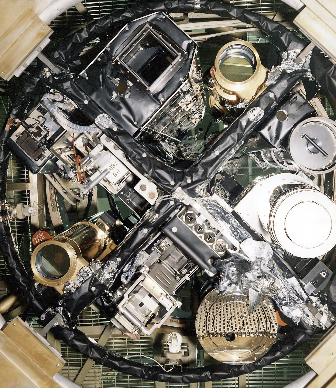
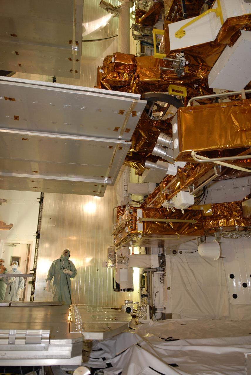
The Apollo Telescope Mount (ATM) was designed and developed by the Marshall Space Flight Center and served as the primary scientific instrument unit aboard Skylab (1973-1979). The ATM contained eight complex astronomical instruments designed to observe the Sun over a wide spectrum from visible light to x-rays. This image depicts the sun end and spar of the ATM flight unit showing individual telescopes. All solar telescopes, the fine Sun sensors, and some auxiliary systems are mounted on the spar, a cruciform lightweight perforated metal mounting panel that divides the canister lengthwise into four equal compartments. The spar assembly was nested inside a cylindrical canister that fit into a complex frame named the rack, and was protected by the solar shield.
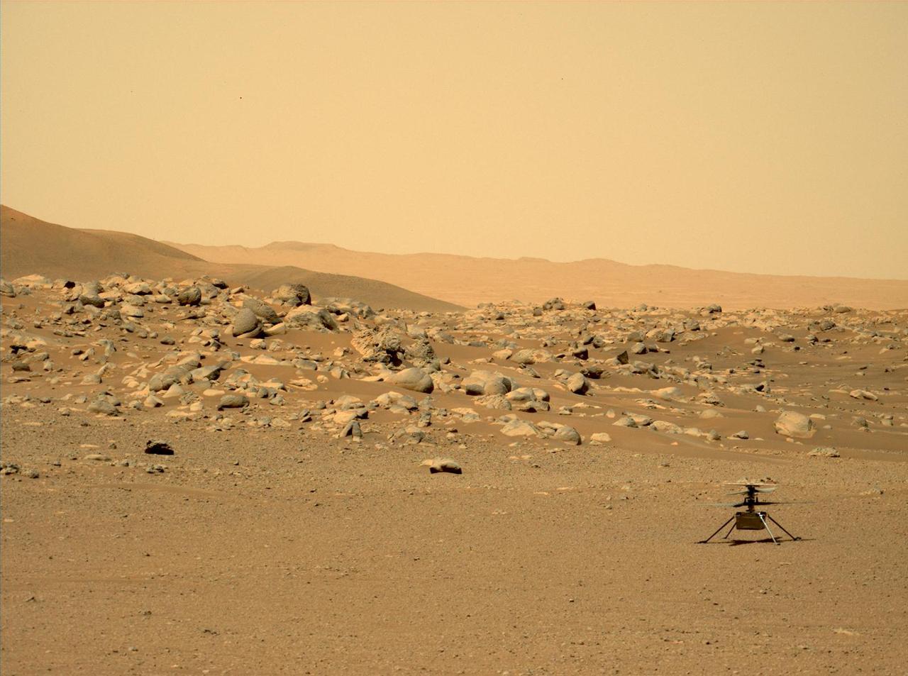
This image of NASA's Ingenuity Mars Helicopter was taken by the Mastcam-Z instrument of the Perseverance rover on June 15, 2021, the 114th Martian day, or sol, of the mission. The location, "Airfield D" (the fourth airfield), is just east of the "Séítah" geologic unit. The image has been processed from the original version. Ingenuity was built by NASA's Jet Propulsion Laboratory in Southern California, which also manages the project for NASA Headquarters. It is supported by NASA's Science Mission Directorate. NASA's Ames Research Center in California's Silicon Valley, and NASA's Langley Research Center in Hampton, Virginia, provided significant flight performance analysis and technical assistance during Ingenuity's development. AeroVironment Inc., Qualcomm, and SolAero also provided design assistance and major vehicle components. Lockheed Martin Space designed and manufactured the Mars Helicopter Delivery System. A key objective for Perseverance's mission on Mars is astrobiology, including the search for signs of ancient microbial life. The rover will characterize the planet's geology and past climate, pave the way for human exploration of the Red Planet, and be the first mission to collect and cache Martian rock and regolith (broken rock and dust). Subsequent NASA missions, in cooperation with ESA (European Space Agency), would send spacecraft to Mars to collect these sealed samples from the surface and return them to Earth for in-depth analysis. https://photojournal.jpl.nasa.gov/catalog/PIA25213
CAPE CANAVERAL, Fla. – In Orbiter Processing Facility 1 at NASA's Kennedy Space Center, a worker from United Space Alliance supervises the closure of the payload bay doors on space shuttle Atlantis. The payload bay has been thoroughly cleaned and is ready to receive the carriers transporting the instruments and equipment needed to service the Hubble Space Telescope. Atlantis is targeted to launch Oct. 8 on the STS-125 mission to service Hubble. The mission crew will perform history-making, on-orbit “surgery” on two important science instruments aboard the telescope. After capturing the telescope, two teams of spacewalking astronauts will perform the repairs during five planned spacewalks. Photo credit: NASA/Jack Pfaller
CAPE CANAVERAL, Fla. – In the Payload Hazardous Servicing Facility at NASA's Kennedy Space Center, workers lift the Fine Guidance Sensor Scientific Instrument Protective Enclosure, or FSIPE, cover before attaching a crane. The cover will be installed on the Orbital Replacement Unit Carrier, or ORUC. The ORUC is one of three carriers that are being prepared for the integration of telescope science instruments, both internal and external replacement components, as well as the flight support equipment to be used by the astronauts during the fifth and final Hubble servicing mission, STS-125. Launch is targeted for Oct. 8. PHoto credit: NASA/Jack Pfaller
CAPE CANAVERAL, Fla. – In the Payload Hazardous Servicing Facility at NASA's Kennedy Space Center, the Fine Guidance Sensor Scientific Instrument Protective Enclosure, or FSIPE, cover awaits a move to be installed on the Orbital Replacement Unit Carrier, or ORUC. The ORUC is one of three carriers that are being prepared for the integration of telescope science instruments, both internal and external replacement components, as well as the flight support equipment to be used by the astronauts during the fifth and final Hubble servicing mission, STS-125. Launch is targeted for Oct. 8. PHoto credit: NASA/Jack Pfaller
CAPE CANAVERAL, Fla. – In the Payload Hazardous Servicing Facility at NASA's Kennedy Space Center, workers help guide the Fine Guidance Sensor Scientific Instrument Protective Enclosure, or FSIPE, cover alongside the Orbital Replacement Unit Carrier, or ORUC, for installation. The ORUC is one of three carriers that are being prepared for the integration of telescope science instruments, both internal and external replacement components, as well as the flight support equipment to be used by the astronauts during the fifth and final Hubble servicing mission, STS-125. Launch is targeted for Oct. 8. PHoto credit: NASA/Jack Pfaller
CAPE CANAVERAL, Fla. – In the Payload Hazardous Servicing Facility at NASA's Kennedy Space Center, the Fine Guidance Sensor Scientific Instrument Protective Enclosure, or FSIPE, cover has been installed on the Orbital Replacement Unit Carrier, or ORUC. The ORUC is one of three carriers that are being prepared for the integration of telescope science instruments, both internal and external replacement components, as well as the flight support equipment to be used by the astronauts during the fifth and final Hubble servicing mission, STS-125. Launch is targeted for Oct. 8. PHoto credit: NASA/Jack Pfaller
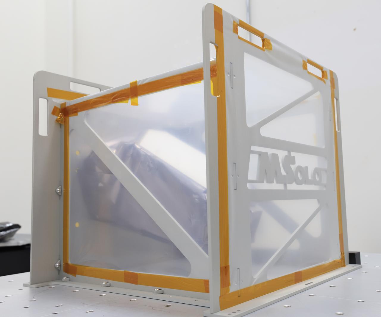
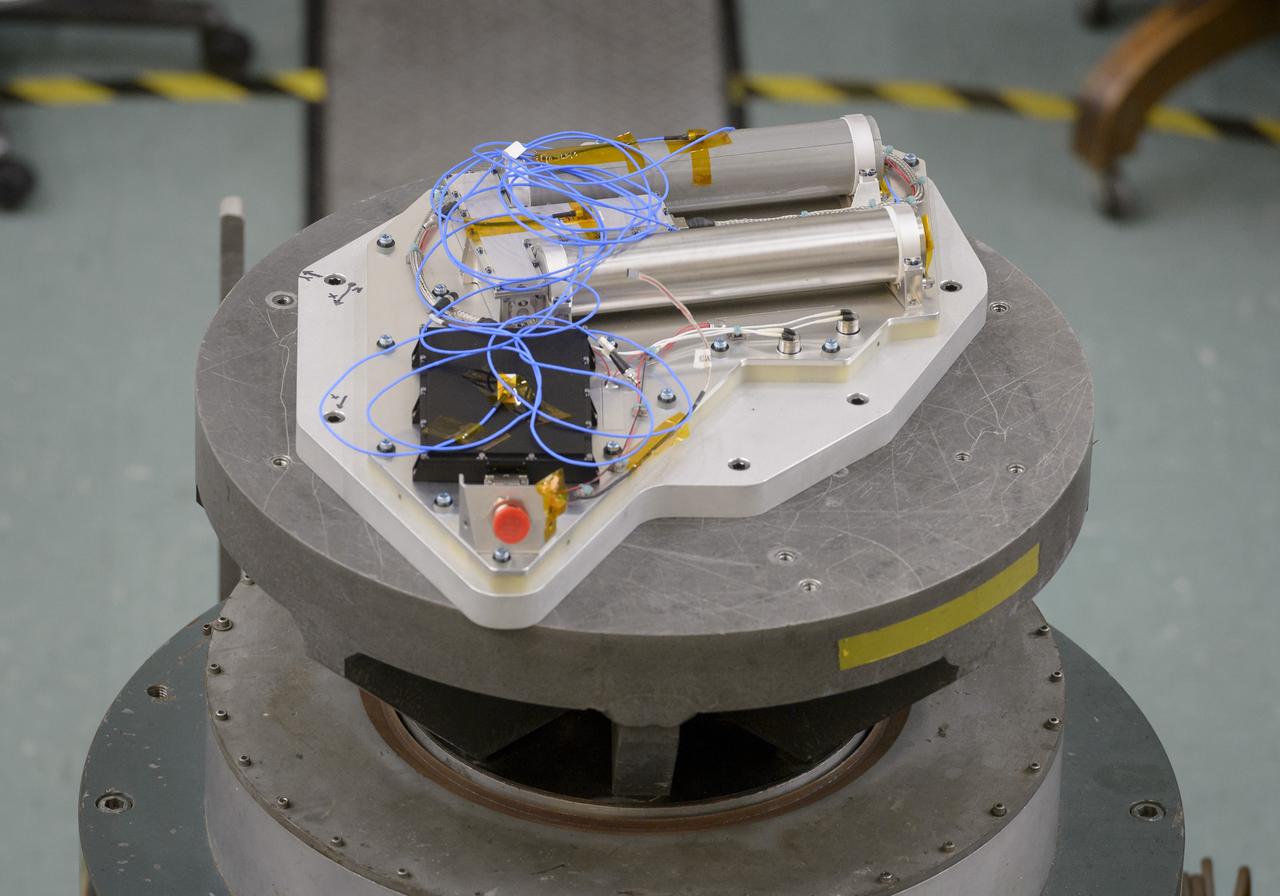
Engineers conduct a mass properties test on the Mass Spectrometer Observing Lunar Operations (MSolo) instrument inside Kennedy Space Center’s Space Station Processing Facility in Florida on Nov. 22, 2022. Mass properties determines the mass and center of gravity of the flight unit. The lander uses this information, from all payloads, to improve stability and performance of the lander – and to a lesser degree, the stability and performance of the rocket. This marks the end of testing at Kennedy for the Polar Resources Ice Mining Experiment-1 (PRIME-1) MSolo instrument. It will soon be shipped to Intuitive Machines in Houston for integration on the NOVA-C landing platform. Launching in 2023, the PRIME-1 mission will be the first in-situ resource utilization demonstration on the Moon.
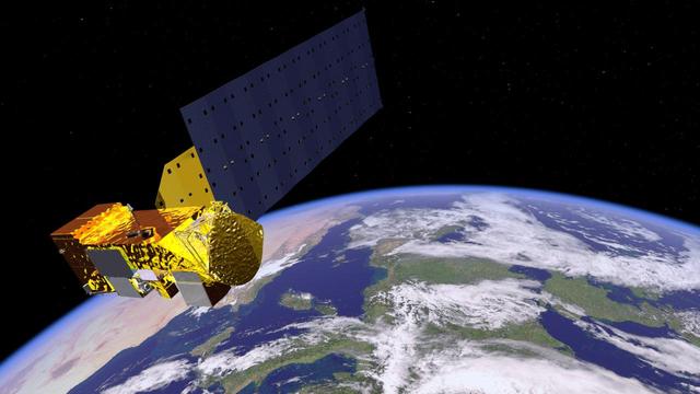
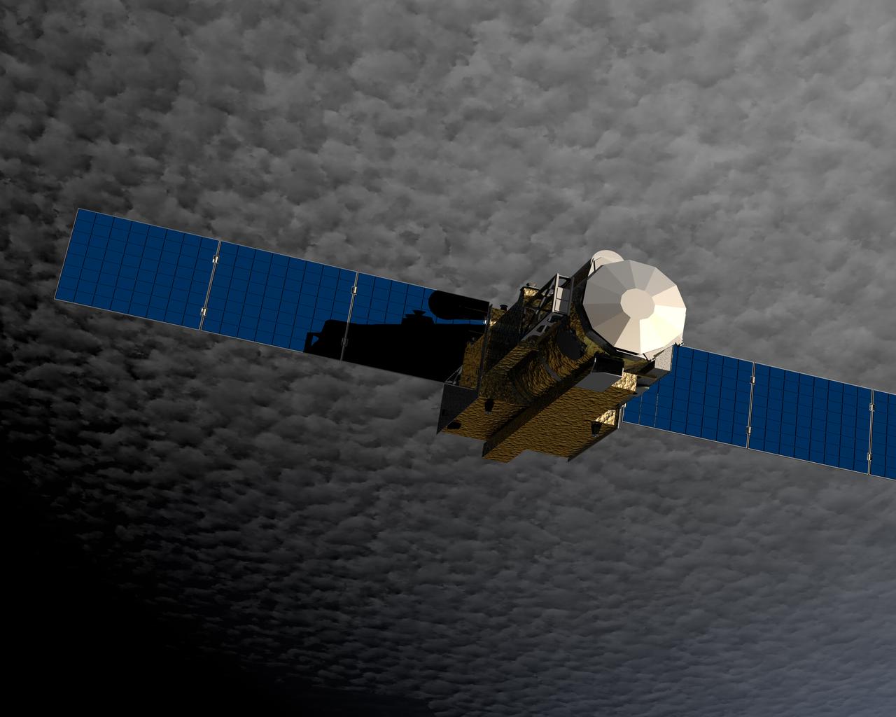
NASA Aqua satellite carries six state-of-the-art instruments in a near-polar low-Earth orbit. Aqua is seen in this artist concept orbiting Earth. The six instruments are the Atmospheric Infrared Sounder (AIRS), the Advanced Microwave Sounding Unit (AMSU-A), the Humidity Sounder for Brazil (HSB), the Advanced Microwave Scanning Radiometer for EOS (AMSR-E), the Moderate Resolution Imaging Spectroradiometer (MODIS), and Clouds and the Earth's Radiant Energy System (CERES). Each has unique characteristics and capabilities, and all six serve together to form a powerful package for Earth observations. http://photojournal.jpl.nasa.gov/catalog/PIA18156
CAPE CANAVERAL, Fla. – In Orbiter Processing Facility 1 at NASA's Kennedy Space Center, a worker from United Space Alliance prepares to close the payload bay doors on space shuttle Atlantis. The payload bay has been thoroughly cleaned and is ready to receive the carriers transporting the instruments and equipment needed to service the Hubble Space Telescope. Atlantis is targeted to launch Oct. 8 on the STS-125 mission to service Hubble. The mission crew will perform history-making, on-orbit “surgery” on two important science instruments aboard the telescope. After capturing the telescope, two teams of spacewalking astronauts will perform the repairs during five planned spacewalks. Photo credit: NASA/Jack Pfaller
CAPE CANAVERAL, Fla. – In the Payload Hazardous Servicing Facility at NASA's Kennedy Space Center, workers help maneuver the Fine Guidance Sensor Scientific Instrument Protective Enclosure, or FSIPE, cover alongside the Orbital Replacement Unit Carrier, or ORUC, for installation. The ORUC is one of three carriers that are being prepared for the integration of telescope science instruments, both internal and external replacement components, as well as the flight support equipment to be used by the astronauts during the fifth and final Hubble servicing mission, STS-125. Launch is targeted for Oct. 8. PHoto credit: NASA/Jack Pfaller
CAPE CANAVERAL, Fla. – In the Payload Hazardous Servicing Facility at NASA's Kennedy Space Center, an overhead crane moves the Fine Guidance Sensor Scientific Instrument Protective Enclosure, or FSIPE, cover to be installed on the Orbital Replacement Unit Carrier, or ORUC, below. The ORUC is one of three carriers that are being prepared for the integration of telescope science instruments, both internal and external replacement components, as well as the flight support equipment to be used by the astronauts during the fifth and final Hubble servicing mission, STS-125. Launch is targeted for Oct. 8. PHoto credit: NASA/Jack Pfaller
The Apollo Telescope Mount (ATM), designed and developed by the Marshall Space Flight Center, served as the primary scientific instrument unit aboard the Skylab. The ATM contained eight complex astronomical instruments designed to observe the Sun over a wide spectrum from visible light to x-rays. This image shows the ATM spar assembly. All solar telescopes, the fine Sun sensors, and some auxiliary systems are mounted on the spar, a cruciform lightweight perforated metal mounting panel that divides the 10-foot long canister lengthwise into four equal compartments. The spar assembly was nested inside a cylindrical canister that fit into the rack, a complex frame, and was protected by the solar shield.
Researchers at NASA’s Ames Research Center in California’s Silicon Valley complete a successful vibration test of the Neutron Spectrometer System or NSS, designed to sniff out water below the surface of the Moon, successfully sailed through a “shake” test to simulate the turbulent conditions of launch. . This is one of the final tests needed to prepare the instrument for a flight to the Moon aboard Astrobotic Technology’s Peregrine lander, as part of the agency’s Commercial Lunar Payload Services program. The vibration test simulates the forces the instrument will be subjected to during launch when the lander blasts off aboard a United Launch Alliance Vulcan Centaur rocket. The NSS will fly on the Volatiles Investigating Polar Exploration Rover, or VIPER.
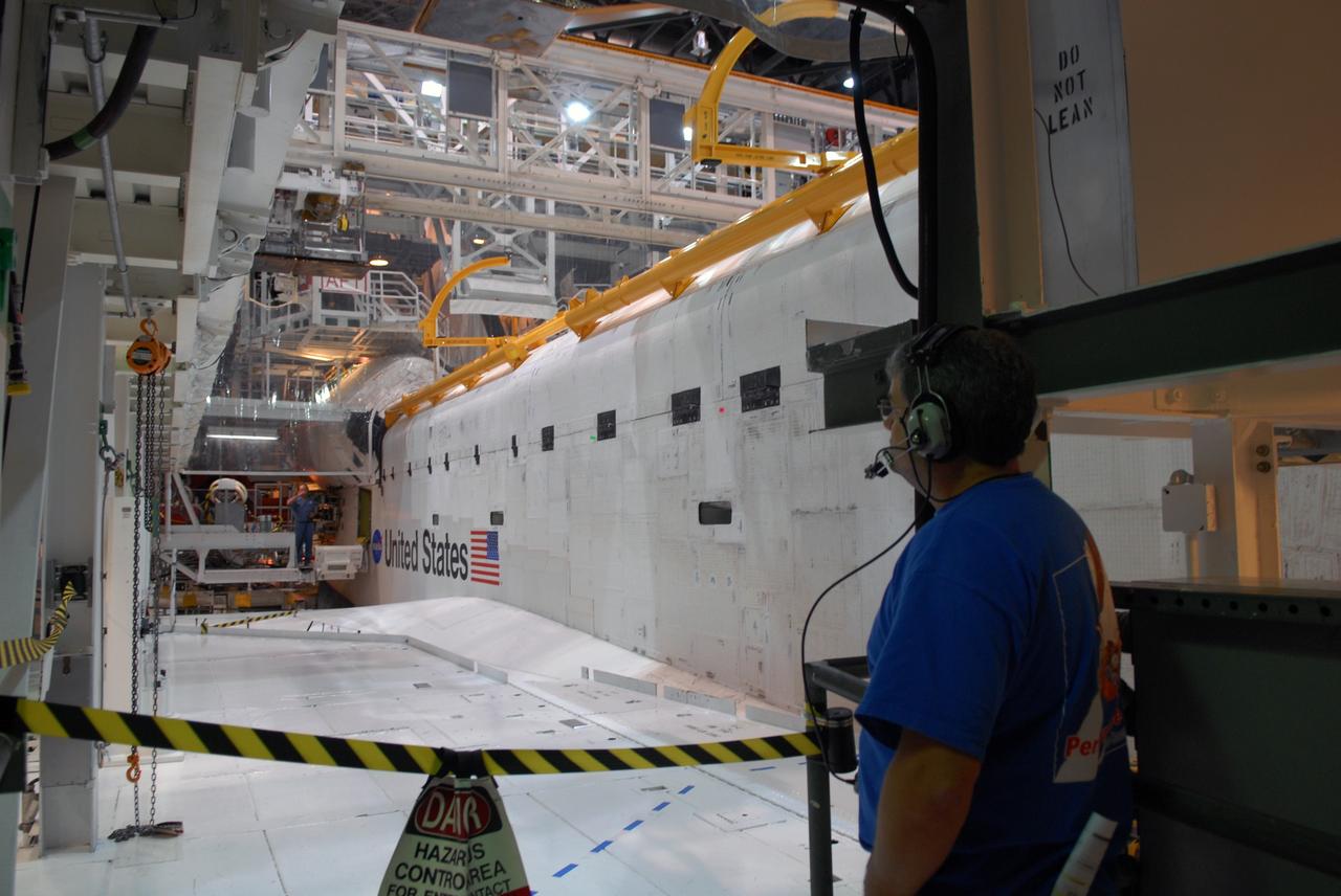
CAPE CANAVERAL, Fla. – In Orbiter Processing Facility 1 at NASA's Kennedy Space Center, a worker from United Space Alliance gives the signal that the payload bay doors on space shuttle Atlantis are closed. The payload bay has been thoroughly cleaned and is ready to receive the carriers transporting the instruments and equipment needed to service the Hubble Space Telescope. Atlantis is targeted to launch Oct. 8 on the STS-125 mission to service Hubble. The mission crew will perform history-making, on-orbit “surgery” on two important science instruments aboard the telescope. After capturing the telescope, two teams of spacewalking astronauts will perform the repairs during five planned spacewalks. Photo credit: NASA/Jack Pfaller
The Apollo Telescope Mount (ATM), designed and developed by the Marshall Space Flight Center, served as the primary scientific instrument unit aboard the Skylab. The ATM contained eight complex astronomical instruments designed to observe the Sun over a wide spectrum from visible light to x-rays. This image shows the ATM spar assembly. All solar telescopes, the fine Sun sensors, and some auxiliary systems are mounted on the spar, a cruciform lightweight perforated metal mounting panel that divides the 10-foot long canister lengthwise into four equal compartments. The spar assembly was nested inside a cylindrical canister that fit into the rack, a complex frame, and was protected by the solar shield.
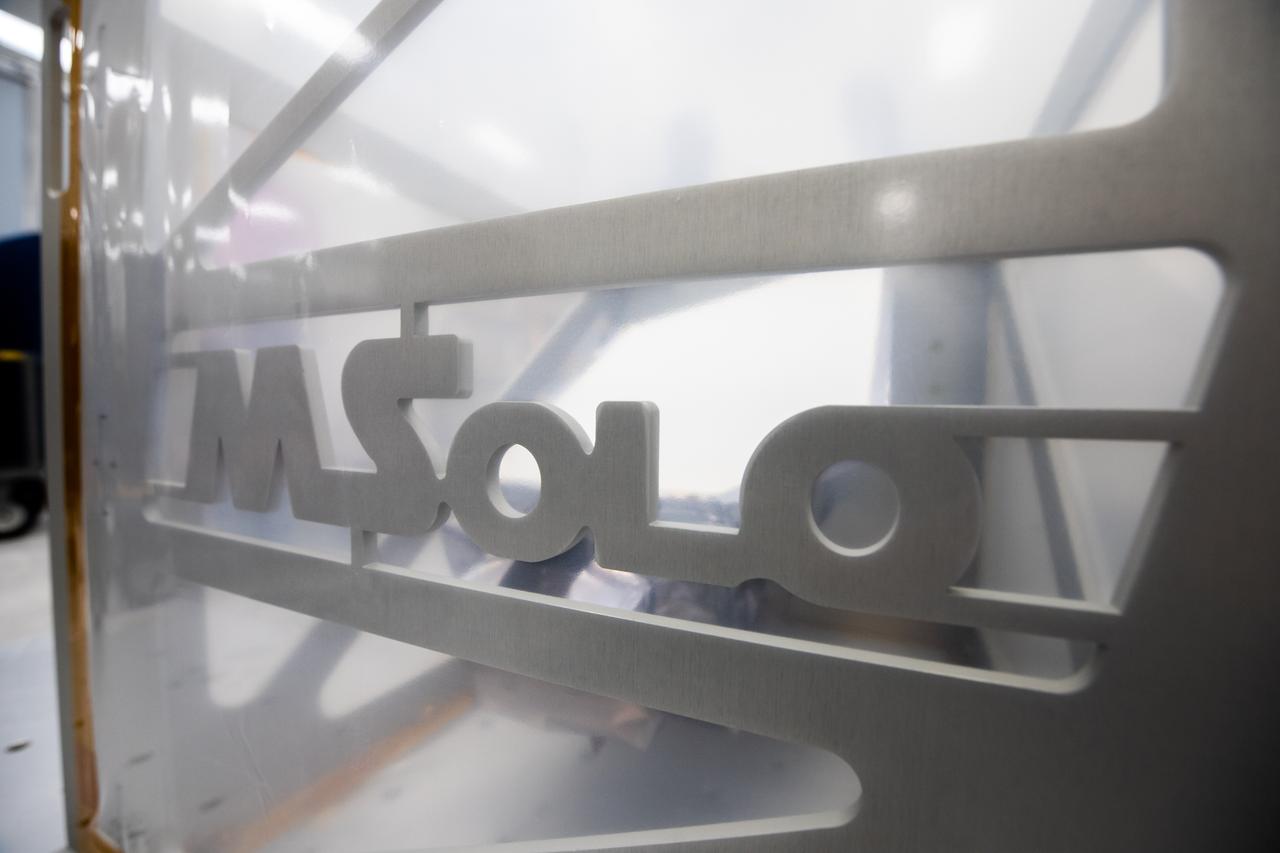
Engineers conduct a mass properties test on the Mass Spectrometer Observing Lunar Operations (MSolo) instrument inside Kennedy Space Center’s Space Station Processing Facility in Florida on Nov. 22, 2022. Mass properties determines the mass and center of gravity of the flight unit. The lander uses this information, from all payloads, to improve stability and performance of the lander – and to a lesser degree, the stability and performance of the rocket. This marks the end of testing at Kennedy for the Polar Resources Ice Mining Experiment-1 (PRIME-1) MSolo instrument. It will soon be shipped to Intuitive Machines in Houston for integration on the NOVA-C landing platform. Launching in 2023, the PRIME-1 mission will be the first in-situ resource utilization demonstration on the Moon.
CAPE CANAVERAL, Fla. – In the Payload Hazardous Servicing Facility at NASA's Kennedy Space Center, workers help maneuver the Fine Guidance Sensor Scientific Instrument Protective Enclosure, or FSIPE, cover into place on the Orbital Replacement Unit Carrier, or ORUC, for installation. The ORUC is one of three carriers that are being prepared for the integration of telescope science instruments, both internal and external replacement components, as well as the flight support equipment to be used by the astronauts during the fifth and final Hubble servicing mission, STS-125. Launch is targeted for Oct. 8. PHoto credit: NASA/Jack Pfaller
CAPE CANAVERAL, Fla. – In the Payload Hazardous Servicing Facility at NASA's Kennedy Space Center, an overhead crane lowers the Fine Guidance Sensor Scientific Instrument Protective Enclosure, or FSIPE, cover alongside the Orbital Replacement Unit Carrier, or ORUC, for installation. The ORUC is one of three carriers that are being prepared for the integration of telescope science instruments, both internal and external replacement components, as well as the flight support equipment to be used by the astronauts during the fifth and final Hubble servicing mission, STS-125. Launch is targeted for Oct. 8. PHoto credit: NASA/Jack Pfaller
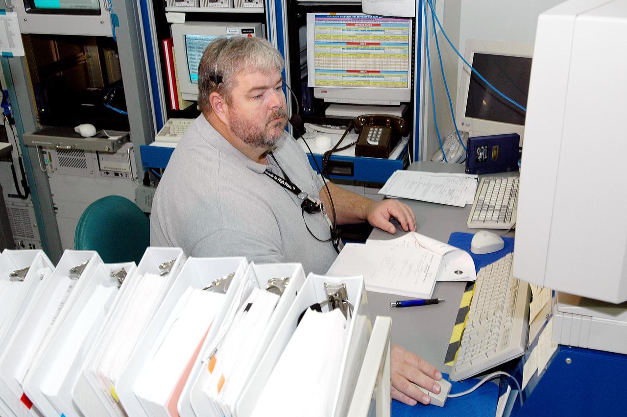
KENNEDY SPACE CENTER, FLA. - Joe Mounts, with Boeing, monitors the Payload Test and Checkout System for the Human Research Facility (HRF) Rack -2 payload. The HRF-2 is scheduled to fly on Return to Flight Space Shuttle mission STS-114. The HRF-2 will deliver additional biomedical instrumentation and research capability to the International Space Station. HRF Rack 1 contains an ultrasound unit and gas analyzer system and has been operational in the U.S. Lab since May 2001. HRF-2 will also be installed in the U. S. Lab and will provide structural, power, thermal, command and data handling, and communication and tracking interfaces between the HRF biomedical instrumentation and the U. S. Lab.
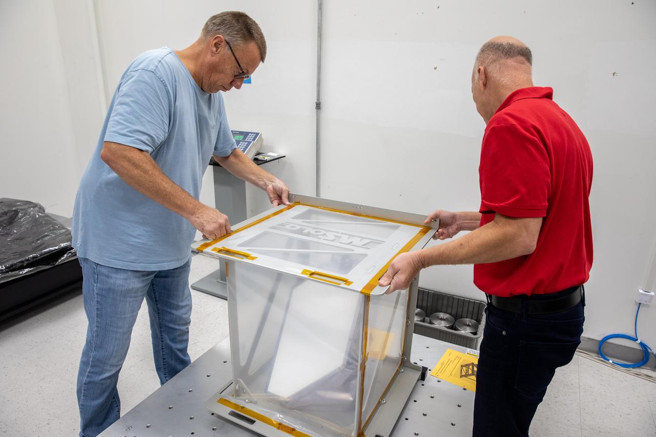
Engineers conduct a mass properties test on the Mass Spectrometer Observing Lunar Operations (MSolo) instrument inside Kennedy Space Center’s Space Station Processing Facility in Florida on Nov. 22, 2022. Mass properties determines the mass and center of gravity of the flight unit. The lander uses this information, from all payloads, to improve stability and performance of the lander – and to a lesser degree, the stability and performance of the rocket. This marks the end of testing at Kennedy for the Polar Resources Ice Mining Experiment-1 (PRIME-1) MSolo instrument. It will soon be shipped to Intuitive Machines in Houston for integration on the NOVA-C landing platform. Launching in 2023, the PRIME-1 mission will be the first in-situ resource utilization demonstration on the Moon.
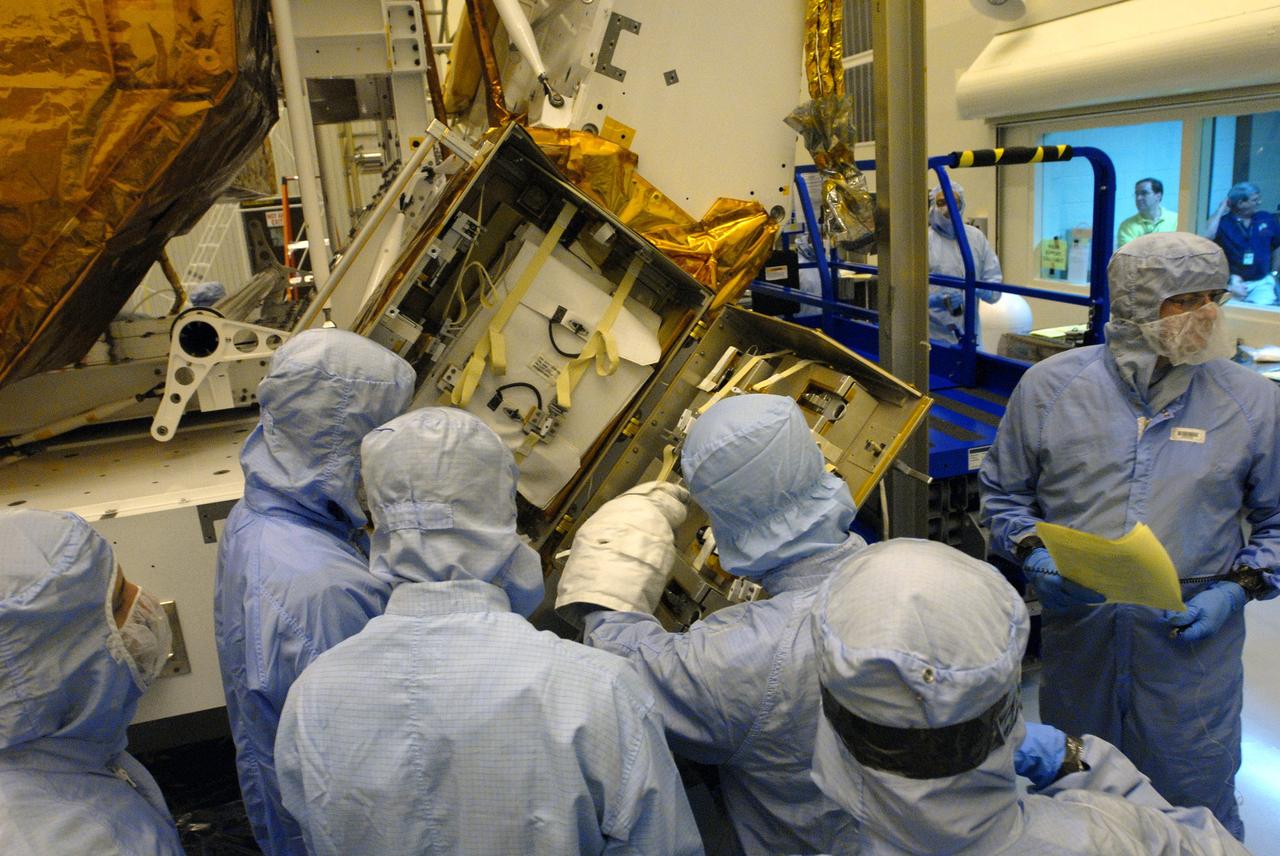
KENNEDY SPACE CENTER, FLORIDA STS-82 PREPARATIONS VIEW --- Payload processing workers in the Kennedy Space Center (KSC) Vertical Processing Facility (VPF) prepare to integrate the Space Telescope Imaging Spectrograph (STIS), suspended at center, into the Orbiter Replacement Unit (ORU) Carrier and Scientific Instrument Protective Enclosure (SIPE). STIS will replace the Goddard High Resolution Spectrograph (GHRS) on the Hubble Space Telescope (HST). Four of the seven STS-82 crew members will perform a series of spacewalks to replace two scientific instruments with two new instruments, including STIS, and perform other tasks during the second HST servicing mission. HST was deployed nearly seven years ago and was initially serviced in 1993.
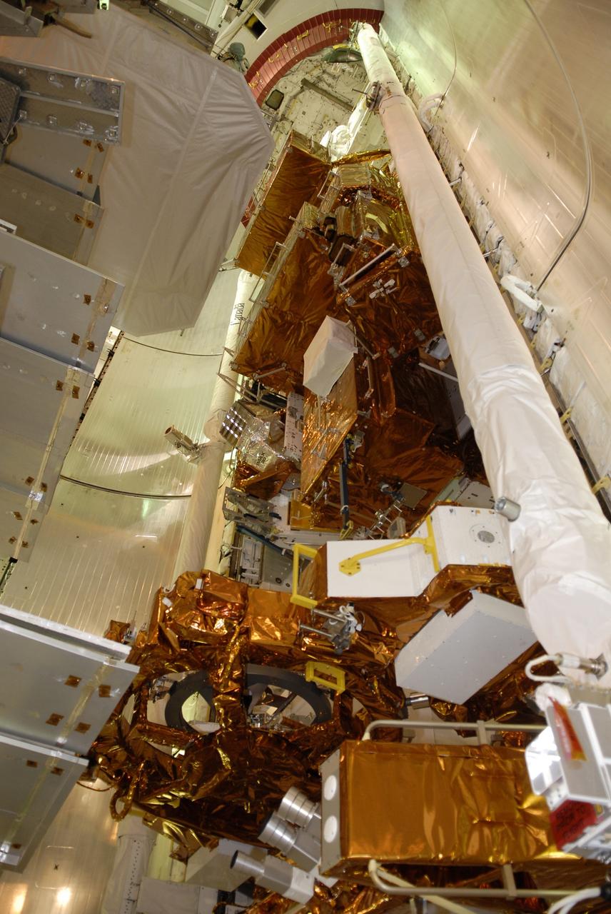
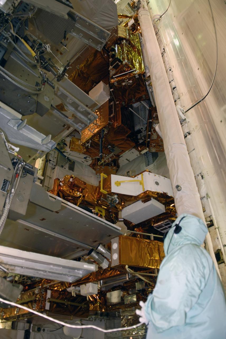
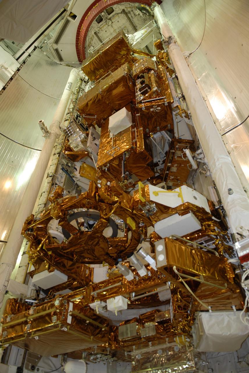
Hinode (Sunrise), formerly known as Solar-B before reaching orbit, was launched from the Uchinoura Space Center in Japan on September 23, 2006. Hinode was designed to probe into the Sun’s magnetic field to better understand the origin of solar disturbances which interfere with satellite communications, electrical power transmission grids, and the safety of astronauts traveling beyond the Earth’s magnetic field. Hinode is circling Earth in a polar orbit that places the instruments in continuous sunlight for nine months each year and allows data dumps to a high latitude European Space Agency (ESA) ground station every orbit. NASA and other science teams will support instrument operations and data collection from the spacecraft’s operation center at the Japanese Aerospace Exploration Agency’s (JAXA’s) Institute of Space and Aeronautical Science facility located in Tokyo. The Hinode spacecraft is a collaboration among space agencies of Japan, the United States, the United Kingdom, and Europe. The Marshall Space Flight Center (MSFC) managed development of three instruments comprising the spacecraft; the Solar Optical Telescope (SOT); the X-Ray Telescope (XRT); and the Extreme Ultraviolet (EUV) Imaging Spectrometer (EIS). Provided by the Multimedia support group at MSFC, this rendering illustrates the Solar-B Spacecraft in earth orbit with its solar panels completely extended.
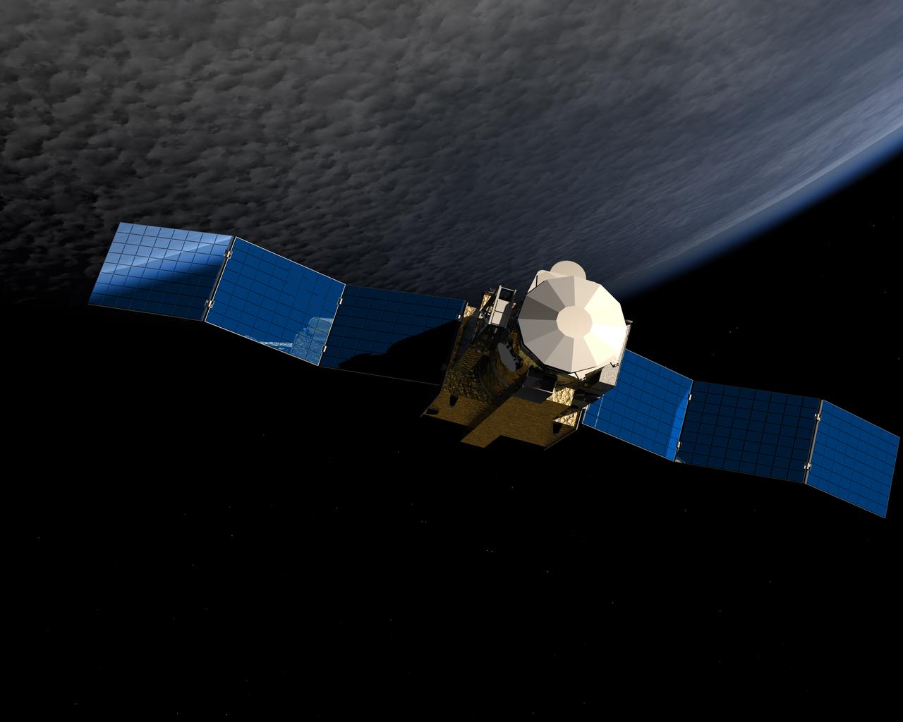
Hinode (Sunrise), formerly known as Solar-B before reaching orbit, was launched from the Uchinoura Space Center in Japan on September 23, 2006. Hinode was designed to probe into the Sun’s magnetic field to better understand the origin of solar disturbances which interfere with satellite communications, electrical power transmission grids, and the safety of astronauts traveling beyond the Earth’s magnetic field. Hinode is circling Earth in a polar orbit that places the instruments in continuous sunlight for nine months each year and allows data dumps to a high latitude European Space Agency (ESA) ground station every orbit. NASA and other science teams will support instrument operations and data collection from the spacecraft’s operation center at the Japanese Aerospace Exploration Agency’s (JAXA’s) Institute of Space and Aeronautical Science facility located in Tokyo. The Hinode spacecraft is a collaboration among space agencies of Japan, the United States, the United Kingdom, and Europe. The Marshall Space Flight Center (MSFC) managed development of three instruments comprising the spacecraft; the Solar Optical Telescope (SOT); the X-Ray Telescope (XRT); and the Extreme Ultraviolet (EUV) Imaging Spectrometer (EIS). Provided by the Multimedia support group at MSFC, this rendering illustrates the Solar-B Spacecraft in earth orbit with its solar panels partially extended.
In the image, taken on June 1, 2019, an engineer in the Spacecraft Assembly Facility's High Bay 1 at NASA's Jet Propulsion Laboratory in Pasadena, California, can be seen working on the exposed belly of the Mars 2020 rover. It has been inverted to allow the 2020 engineers and technicians easier access. The front of the rover is on camera left. The engineer is inspecting wiring directly above the Mars Oxygen In-Situ Resource Utilization Experiment (MOXIE) instrument. MOXIE will demonstrate a way that future explorers might produce oxygen from the Martian atmosphere for propellant and for breathing. In the foreground, just to the left of center and distinctive because of the relative lack of wiring, is the body unit for the SuperCam instrument. The mast unit for SuperCam instrument, which will provide imaging, chemical composition analysis, and mineralogy from its high perch at the top of the rover's remote sensing mast was installed June 25. To the far left, covered by a red-colored shield, is the bay where the Adaptive Caching Assembly (ACA) will document, analyze and process for storage samples of Mars rock and soil for future return to Earth. https://photojournal.jpl.nasa.gov/catalog/PIA23312

Hinode (Sunrise), formerly known as Solar-B before reaching orbit, was launched from the Uchinoura Space Center in Japan on September 23, 2006. Hinode was designed to probe into the Sun’s magnetic field to better understand the origin of solar disturbances which interfere with satellite communications, electrical power transmission grids, and the safety of astronauts traveling beyond the Earth’s magnetic field. Hinode is circling Earth in a polar orbit that places the instruments in continuous sunlight for nine months each year and allows data dumps to a high latitude European Space Agency (ESA) ground station every orbit. NASA and other science teams will support instrument operations and data collection from the spacecraft’s operation center at the Japanese Aerospace Exploration Agency’s (JAXA’s) Institute of Space and Aeronautical Science facility located in Tokyo. The Hinode spacecraft is a collaboration among space agencies of Japan, the United States, the United Kingdom, and Europe. The Marshall Space Flight Center (MSFC) managed development of three instruments comprising the spacecraft; the Solar Optical Telescope (SOT); the X-Ray Telescope (XRT); and the Extreme Ultraviolet (EUV) Imaging Spectrometer (EIS). This image of a sunspot, taken by Hinode, is a prime example of what the spacecraft can offer.
NM23-48-009 (29 April 1997) --- United States astronaut Jerry M. Linenger, cosmonaut guest researcher, works outside the Russian Mir Space Station during a joint United States-Russian space walk on April 29, 1997. He was joined by Mir-23 commander Vasili V. Tsibliyev (out of frame) for the five-hour Extravehicular Activity (EVA) designed to deploy scientific instruments and retrieve other science hardware. At the top of the frame is a Russian Progress re-supply capsule docked to the Mir’s Kvant-1 module.
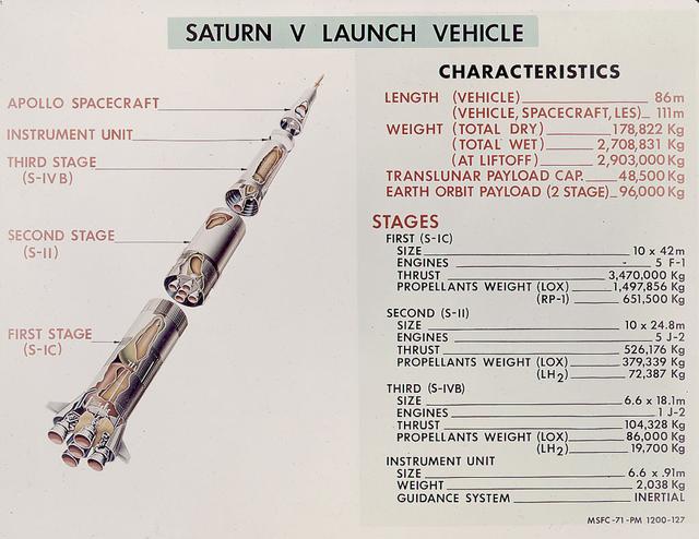
This is a good cutaway diagram of the Saturn V launch vehicle showing the three stages, the instrument unit, and the Apollo spacecraft. The chart on the right presents the basic technical data in clear metric detail. The Saturn V is the largest and most powerful launch vehicle in the United States. The towering, 111 meter, Saturn V was a multistage, multiengine launch vehicle standing taller than the Statue of Liberty. Altogether, the Saturn V engines produced as much power as 85 Hoover Dams. Development of the Saturn V was the responsibility of the Marshall Space Flight Center at Huntsville, Alabama, directed by Dr. Wernher von Braun.
CAPE CANAVERAL, Fla. – In the Payload Hazardous Servicing Facility at NASA's Kennedy Space Center in Florida, technicians look over the Science Instrument Command and Data Handling Unit, or SIC&DH. The SIC&DH will be installed on the Multi-Use Lightweight Equipment Carrier in the facility. The SIC&DH will be installed on the Hubble Space Telescope during space shuttle Atlantis' STS-125 mission. This unit will replace the one that suffered a failure aboard the orbiting telescope on Sept. 27, 2008. Atlantis is targeted for launch on May 12. Photo credit: NASA/Dimitri Gerondidakis
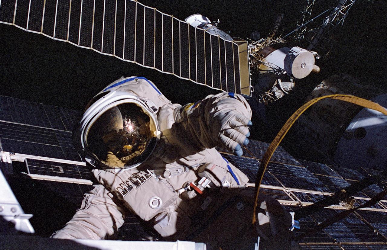
NM23-48-009 (29 April 1997) --- United States astronaut Jerry M. Linenger, cosmonaut guest researcher, works outside the Russian Mir Space Station during a joint United States-Russian space walk on April 29, 1997. He was joined by Mir-23 commander Vasili V. Tsibliyev (out of frame) for the five-hour Extravehicular Activity (EVA) designed to deploy scientific instruments and retrieve other science hardware. At the top of the frame is a Russian Progress re-supply capsule docked to the Mir’s Kvant-1 module.
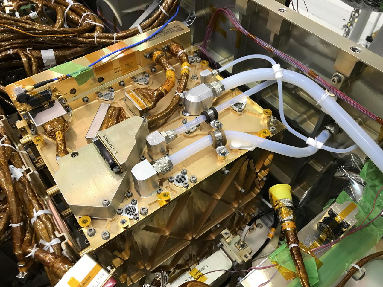
In this image, the gold-plated Mars Oxygen In-Situ Resource Utilization Experiment (MOXIE) Instrument shines after being installed inside the Perseverance rover. The largest white tube on the top surface of MOXIE takes in filtered carbon dioxide-rich Martian atmosphere. That CO2 is pressurized and passed through the Solid Oxide Electrolysis unit, where it is split into carbon monoxide and oxygen. The smallest tube snaking across the top of the unit sends the oxygen produced by MOXIE through a composition sensor to measure purity, then vents the oxygen out to the Martian atmosphere. This technology demonstration may guide the design of future, larger devices that could enable human exploration of Mars. https://photojournal.jpl.nasa.gov/catalog/PIA24203
CAPE CANAVERAL, Fla. – The Science Instrument Command and Data Handling Unit, or SIC&DH, arrives at NASA's Kennedy Space Center in Florida. The SIC&DH will be installed on the Hubble Space Telescope during space shuttle Atlantis' STS-125 mission. This unit will replace the one that suffered a failure aboard the orbiting telescope on Sept. 27, 2008. The SIC&DH is being prepared for integration onto the Multi-Use Lightweight Equipment Carrier in the Payload Hazardous Servicing Facility. The carrier holds the payload for space shuttle Atlantis' STS-125 mission servicing NASA's Hubble Space Telescope, targeted to launch May 12. Photo credit: NASA/Jack Pfaller
CAPE CANAVERAL, Fla. – The Science Instrument Command and Data Handling Unit, or SIC&DH, is transferred inside the Payload Hazardous Servicing Facility at NASA's Kennedy Space Center in Florida. The SIC&DH will be installed on the Hubble Space Telescope during space shuttle Atlantis' STS-125 mission. This unit will replace the one that suffered a failure aboard the orbiting telescope on Sept. 27, 2008. The SIC&DH is being prepared for integration onto the Multi-Use Lightweight Equipment Carrier .The carrier holds the payload for space shuttle Atlantis' STS-125 mission servicing NASA's Hubble Space Telescope, targeted to launch May 12. Photo credit: NASA/Jack Pfaller
CAPE CANAVERAL, Fla. – In the Payload Hazardous Servicing Facility at NASA's Kennedy Space Center in Florida, a technician helps with the lifting of the Science Instrument Command and Data Handling Unit, or SIC&DH. The unit will be placed on a stand until it is installed on the Multi-Use Lightweight Equipment Carrier. The SIC&DH will be installed on the Hubble Space Telescope during space shuttle Atlantis' STS-125 mission, replacing one that suffered a failure aboard the orbiting telescope on Sept. 27, 2008. The carrier holds the payload for space shuttle Atlantis' STS-125 mission servicing NASA's Hubble Space Telescope, targeted to launch May 12. Photo credit: NASA/Jack Pfaller
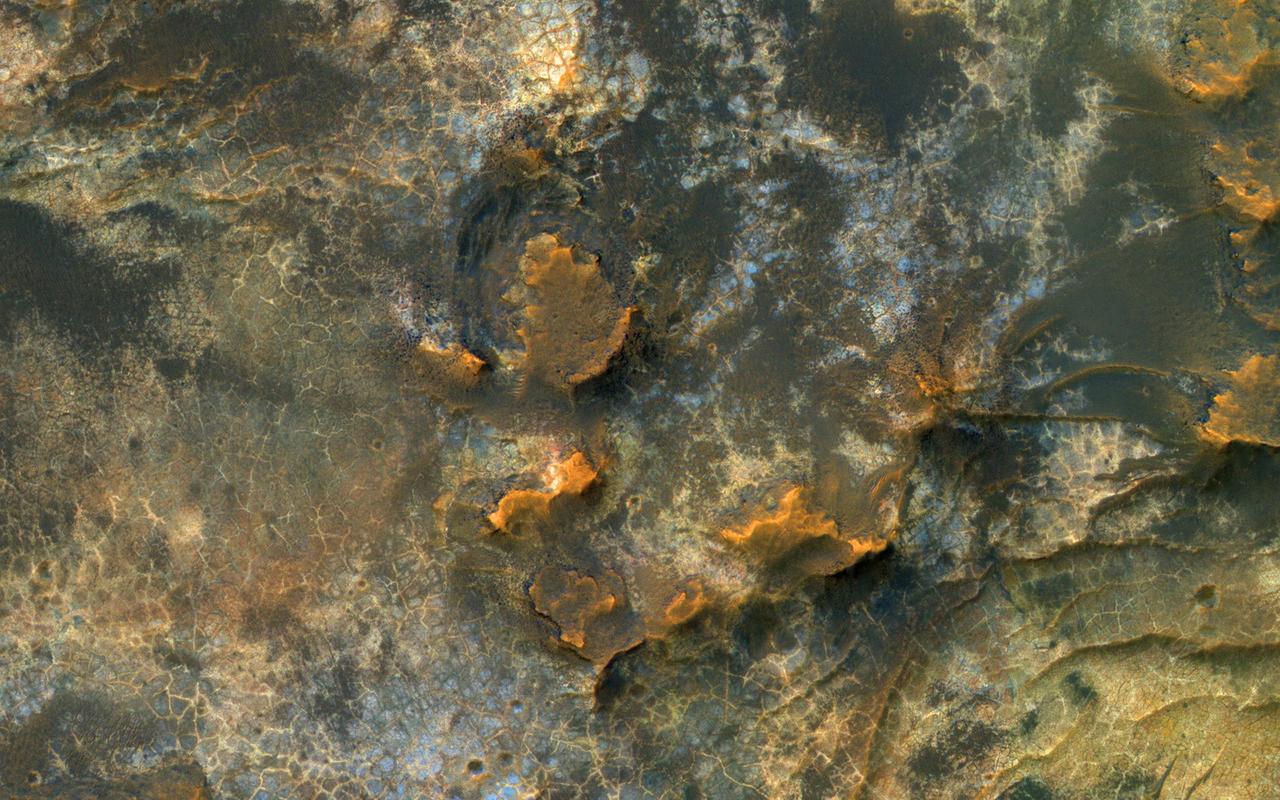
HiRISE reveals small-scale shapes that often correlate with mineral units and provides information about stratigraphy (i.e., what's on top and relative ages). This image was acquired for co-analysis with a spectrometer instrument also on our spacecraft called CRISM (Compact Reconnaissance Imaging Spectrometer for Mars). It shows polygonal units that match clay-rich areas. Plus, this region is colorful! This location, in Eridania Basin, was the site of an ancient lake, so these clay-rich sediments may have been habitable. While CRISM cannot acquire new data from their infrared channel due to lack of cooling, they have acquired much previous data that lacks HiRISE coverage. https://photojournal.jpl.nasa.gov/catalog/PIA23105
CAPE CANAVERAL, Fla. – In the Payload Hazardous Servicing Facility at NASA's Kennedy Space Center in Florida, technicians remove the shipping cover from the Science Instrument Command and Data Handling Unit, or SIC&DH. The SIC&DH will be installed on the Hubble Space Telescope during space shuttle Atlantis' STS-125 mission. This unit will replace the one that suffered a failure aboard the orbiting telescope on Sept. 27, 2008. The SIC&DH is being prepared for integration onto the Multi-Use Lightweight Equipment Carrier .The carrier holds the payload for space shuttle Atlantis' STS-125 mission servicing NASA's Hubble Space Telescope, targeted to launch May 12. Photo credit: NASA/Jack Pfaller
KENNEDY SPACE CENTER, FLA. -- The Saturn IB booster for the United States mission of the Apollo Soyuz Test Project is shown on its mobile launcher in a Vehicle Assembly Building high bay with a boilerplate Apollo spacecraft installed atop the instrument unit. The encapsulated Apollo spacecraft, docking module and docking adapter that will be launched atop the Chrysler-built booster will replace the boilerplate spacecraft prior to rollout of the space vehicle to Complex 39's Pad B, now scheduled March 24. Launch is scheduled at 3:50 p.m. EDT July 15.
On March 28, 2024 NASA held its 2023 Administrator’s Agency Honor Awards at the Glenn Research Center in Cleveland, OH. This celebratory event recognized the invaluable contributions of civil servants and contractors alike, each one instrumental in propelling humanity further into the realms of space exploration, understanding, and discoverThis is NASA's highest form of recognition that is awarded to any Government employee who, by distinguished service, ability, or vision has personally contributed to NASA's advancement of United States' interests.
On March 28, 2024 NASA held its 2023 Administrator’s Agency Honor Awards at the Glenn Research Center in Cleveland, OH. This celebratory event recognized the invaluable contributions of civil servants and contractors alike, each one instrumental in propelling humanity further into the realms of space exploration, understanding, and discoverThis is NASA's highest form of recognition that is awarded to any Government employee who, by distinguished service, ability, or vision has personally contributed to NASA's advancement of United States' interests.
On March 28, 2024 NASA held its 2023 Administrator’s Agency Honor Awards at the Glenn Research Center in Cleveland, OH. This celebratory event recognized the invaluable contributions of civil servants and contractors alike, each one instrumental in propelling humanity further into the realms of space exploration, understanding, and discoverThis is NASA's highest form of recognition that is awarded to any Government employee who, by distinguished service, ability, or vision has personally contributed to NASA's advancement of United States' interests.
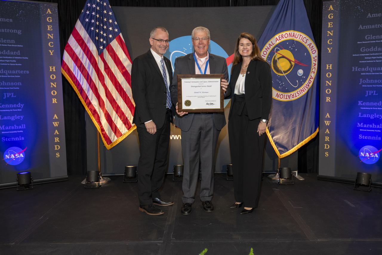
On March 28, 2024 NASA held its 2023 Administrator’s Agency Honor Awards at the Glenn Research Center in Cleveland, OH. This celebratory event recognized the invaluable contributions of civil servants and contractors alike, each one instrumental in propelling humanity further into the realms of space exploration, understanding, and discoverThis is NASA's highest form of recognition that is awarded to any Government employee who, by distinguished service, ability, or vision has personally contributed to NASA's advancement of United States' interests.
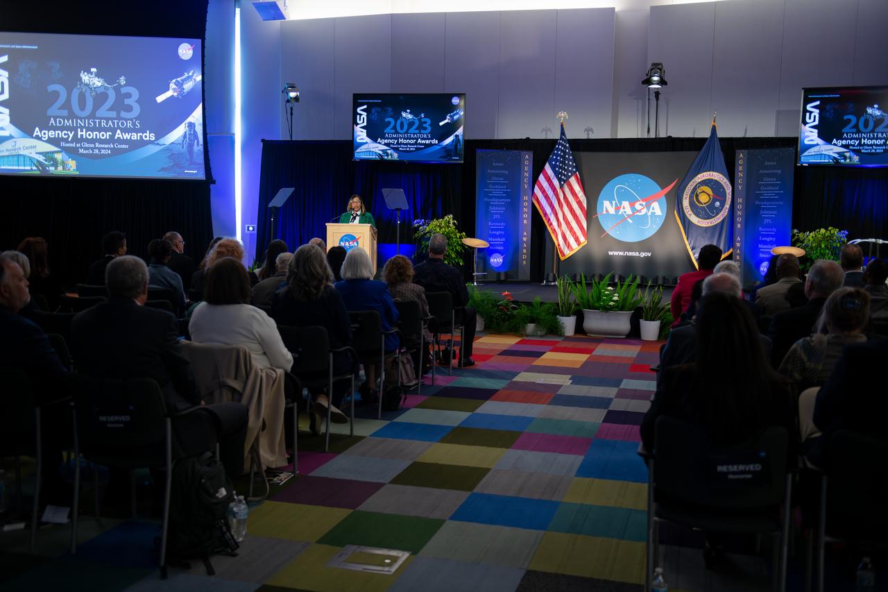
On March 28, 2024 NASA held its 2023 Administrator’s Agency Honor Awards at the Glenn Research Center in Cleveland, OH. This celebratory event recognized the invaluable contributions of civil servants and contractors alike, each one instrumental in propelling humanity further into the realms of space exploration, understanding, and discoverThis is NASA's highest form of recognition that is awarded to any Government employee who, by distinguished service, ability, or vision has personally contributed to NASA's advancement of United States' interests.
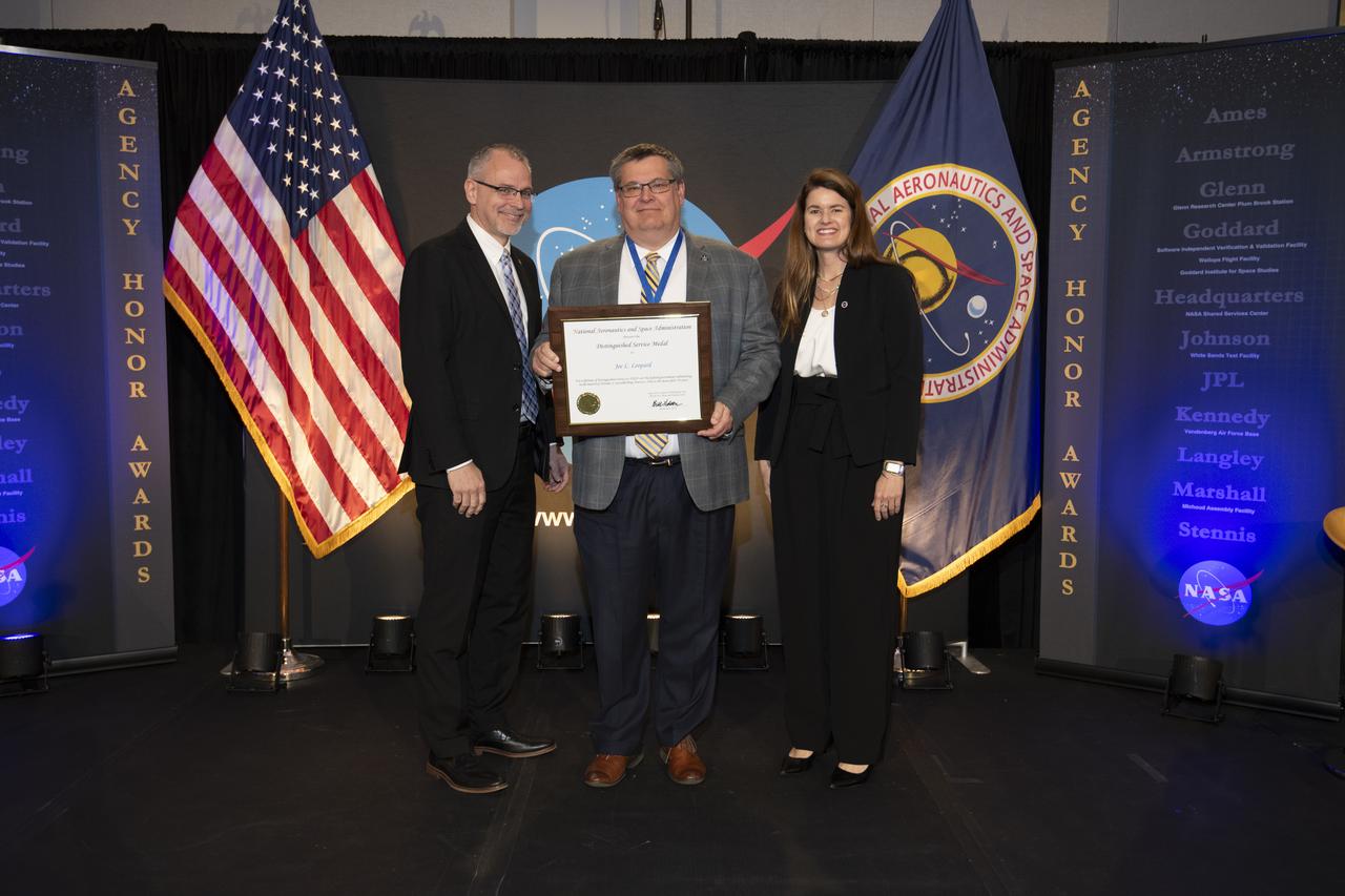
On March 28, 2024 NASA held its 2023 Administrator’s Agency Honor Awards at the Glenn Research Center in Cleveland, OH. This celebratory event recognized the invaluable contributions of civil servants and contractors alike, each one instrumental in propelling humanity further into the realms of space exploration, understanding, and discoverThis is NASA's highest form of recognition that is awarded to any Government employee who, by distinguished service, ability, or vision has personally contributed to NASA's advancement of United States' interests.