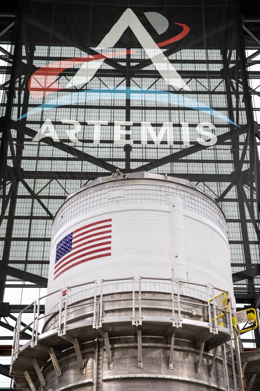
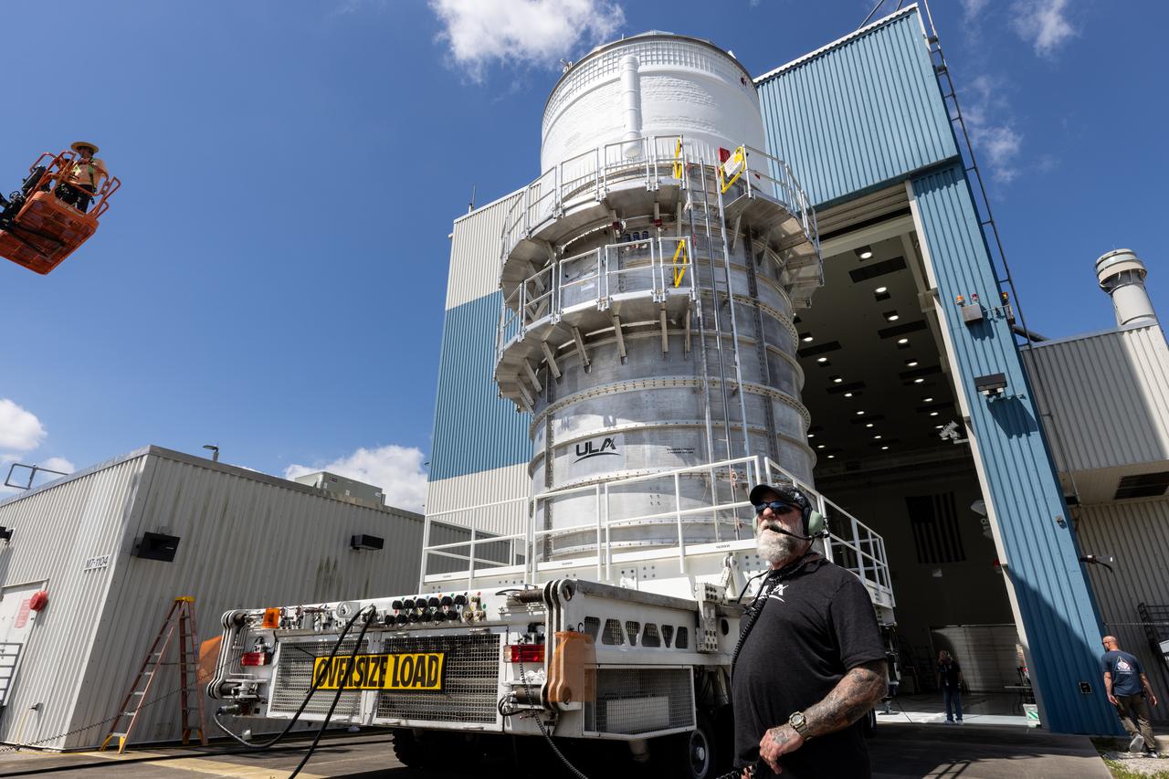
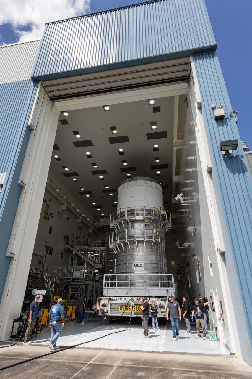
The upper stage for NASA’s Artemis II SLS (Space Launch System) rocket sits in the transfer aisle of the Vehicle Assembly Building at NASA’s Kennedy Space Center in Florida on Wednesday, April 16, 2025, after teams with the agency’s Exploration Ground Systems Program transported the four-story propulsion system from the spaceport’s Multi-Payload Processing Facility (MPPF). Technicians fueled the SLS upper stage, known as the interim cryogenic propulsion stage, with hydrazine for its reaction control system at the MPPF and will now integrate the four-story propulsion system with SLS rocket elements atop mobile launcher 1.
The upper stage for NASA’s Artemis II SLS (Space Launch System) rocket sits in the transfer aisle of the Vehicle Assembly Building at NASA’s Kennedy Space Center in Florida on Wednesday, April 16, 2025, after teams with the agency’s Exploration Ground Systems Program transported the four-story propulsion system from the spaceport’s Multi-Payload Processing Facility (MPPF). Technicians fueled the SLS upper stage, known as the interim cryogenic propulsion stage, with hydrazine for its reaction control system at the MPPF and will now integrate the four-story propulsion system with SLS rocket elements atop mobile launcher 1.
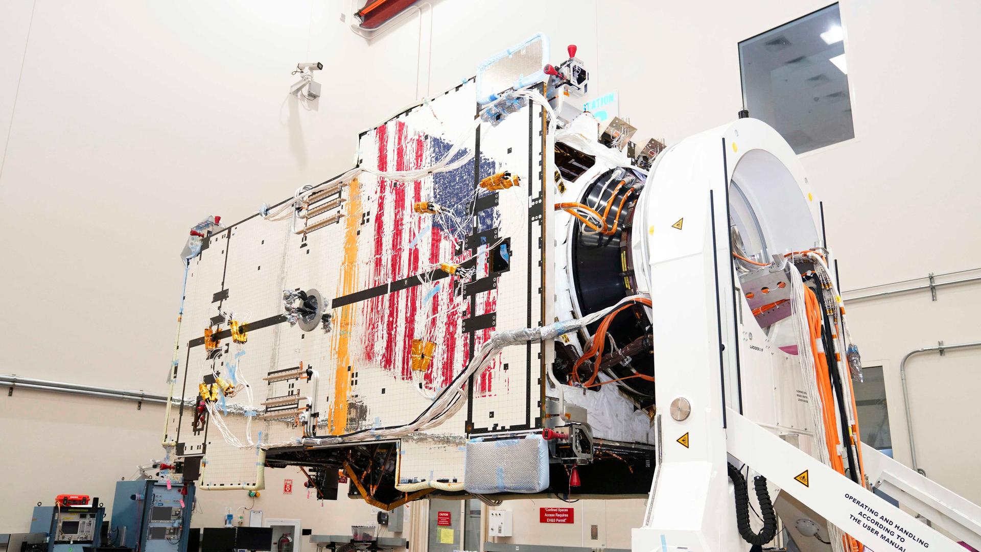
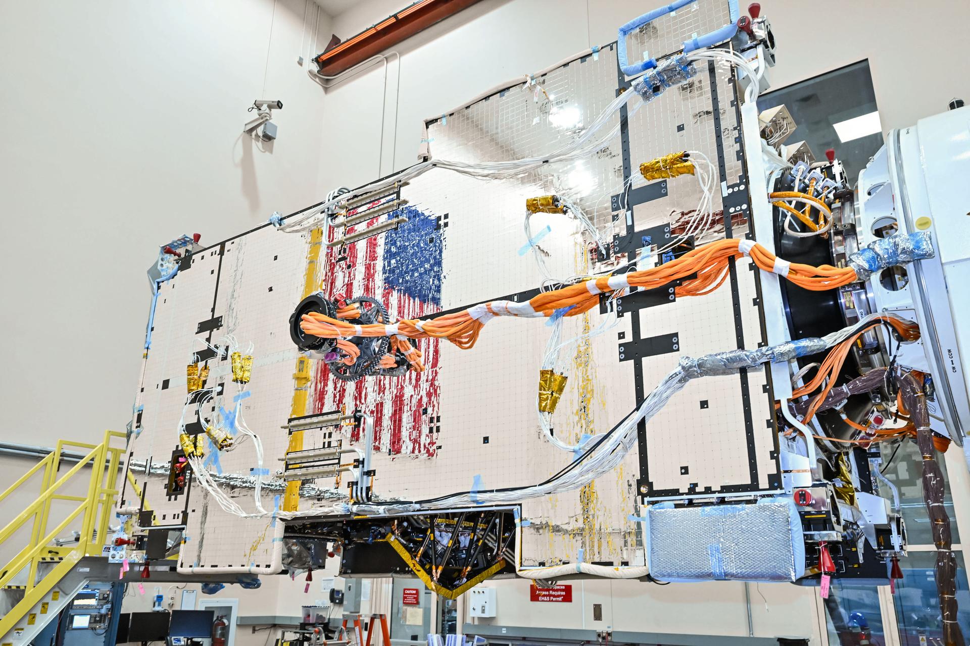
Gateway’s Power and Propulsion Element (PPE) undergoes battery installations at Lanteris Space Systems in Palo Alto, California, in January 2026. PPE is a 60-kilowatt solar electric propulsion spacecraft that will supply the lunar space station with power, high-rate communications, attitude control, orbit maintenance, and orbit transfer capabilities. Its design is based on Lanteris Space Systems’ commercial 1300 bus, enhanced with the most powerful Advanced Electric Propulsion System (AEPS) thrusters and the largest roll-out solar arrays (ROSAs) ever developed. Lanteris Space Systems is the lead industry partner for PPE’s design, manufacturing, and integration.
Gateway’s Power and Propulsion Element (PPE) undergoes battery installations at Lanteris Space Systems in Palo Alto, California, in January 2026. PPE is a 60-kilowatt solar electric propulsion spacecraft that will supply the lunar space station with power, high-rate communications, attitude control, orbit maintenance, and orbit transfer capabilities. Its design is based on Lanteris Space Systems’ commercial 1300 bus, enhanced with the most powerful Advanced Electric Propulsion System (AEPS) thrusters and the largest roll-out solar arrays (ROSAs) ever developed. Lanteris Space Systems is the lead industry partner for PPE’s design, manufacturing, and integration.
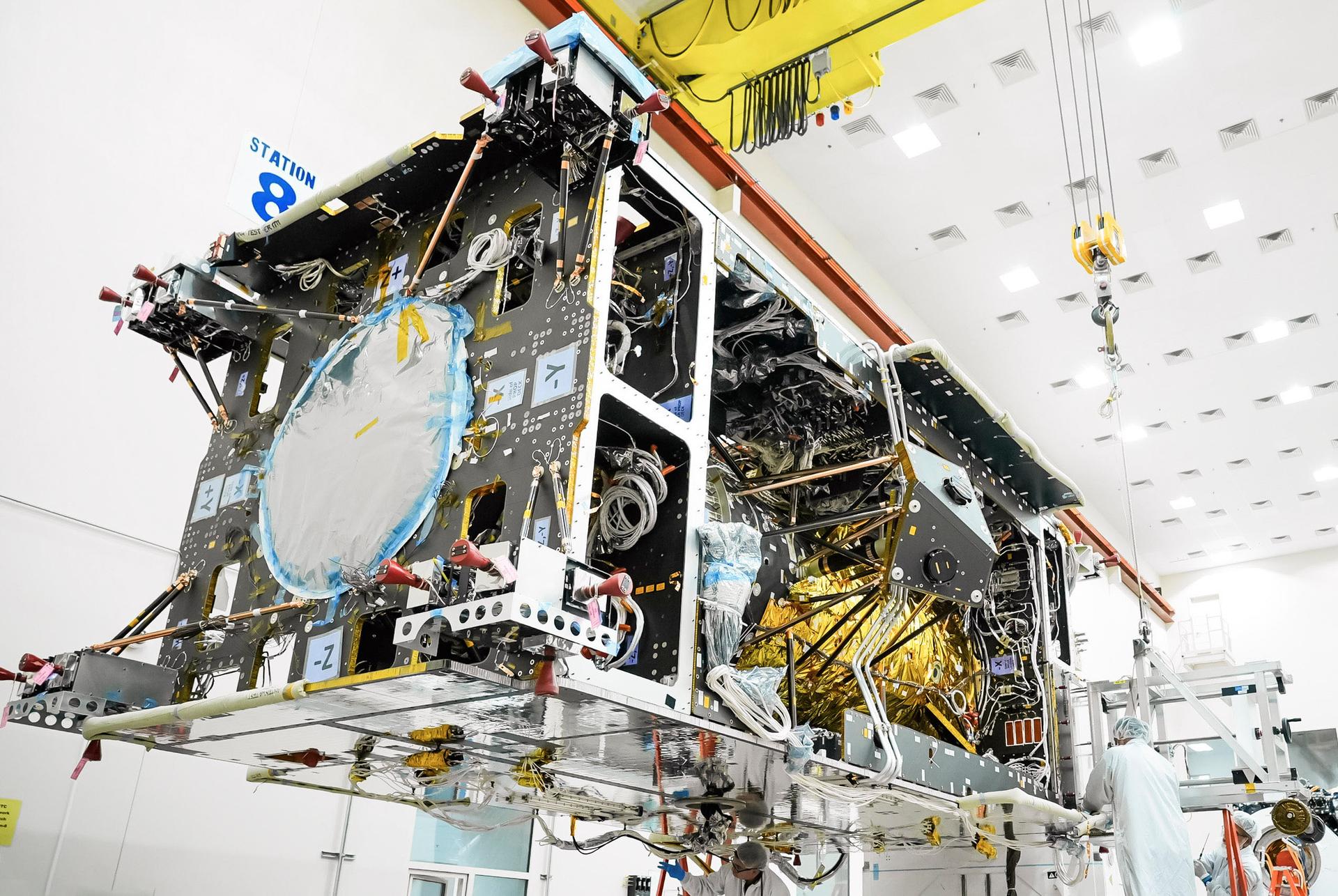
Gateway’s Power and Propulsion Element (PPE) undergoes flight software uploads at Lanteris Space Systems in Palo Alto, California, in January 2026. PPE is a 60-kilowatt solar electric propulsion spacecraft that will supply the lunar space station with power, high-rate communications, attitude control, orbit maintenance, and orbit transfer capabilities. Its design is based on Lanteris Space Systems’ commercial 1300 bus, enhanced with the most powerful Advanced Electric Propulsion System (AEPS) thrusters and the largest roll-out solar arrays (ROSAs) ever developed. Lanteris Space Systems is the lead industry partner for PPE’s design, manufacturing, and integration.

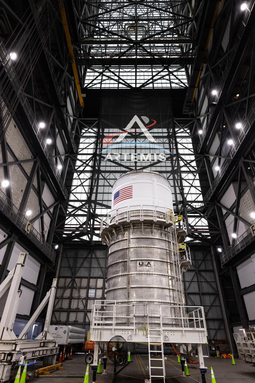
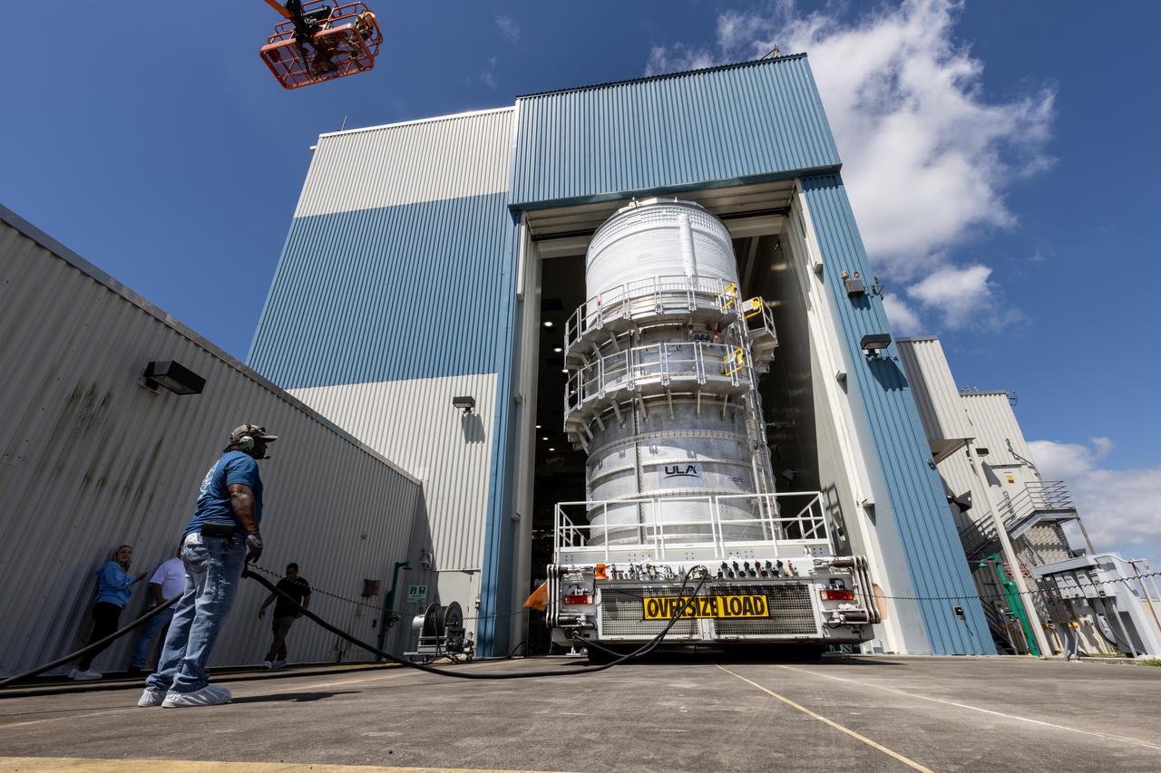
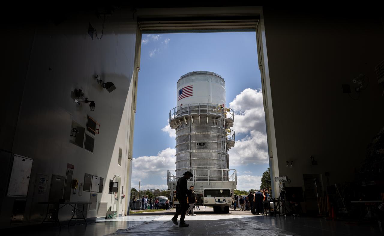
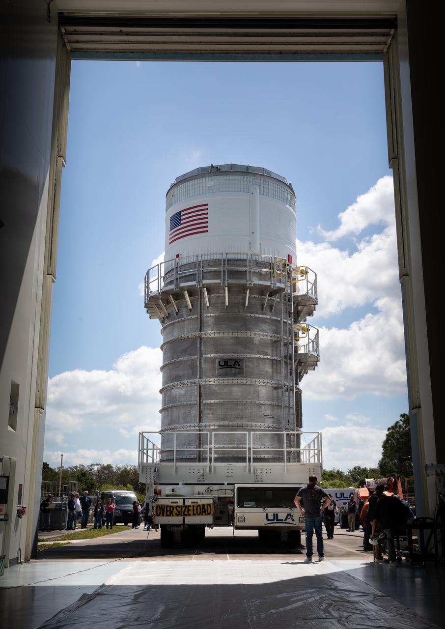
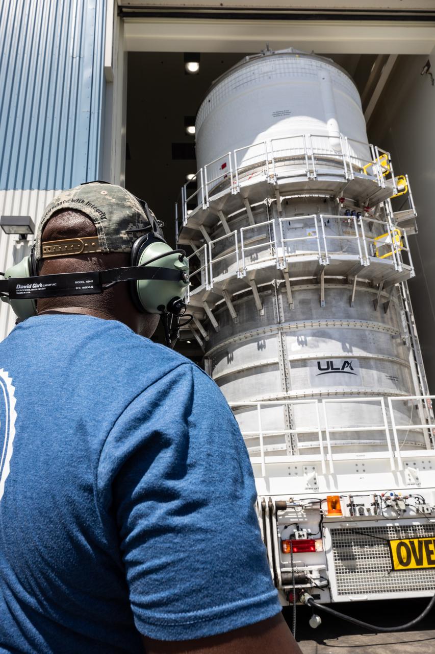
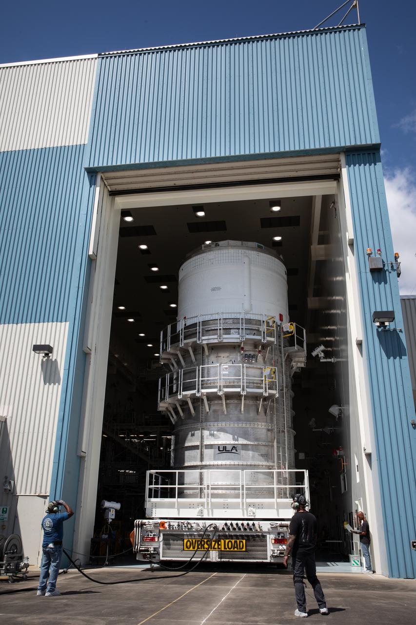
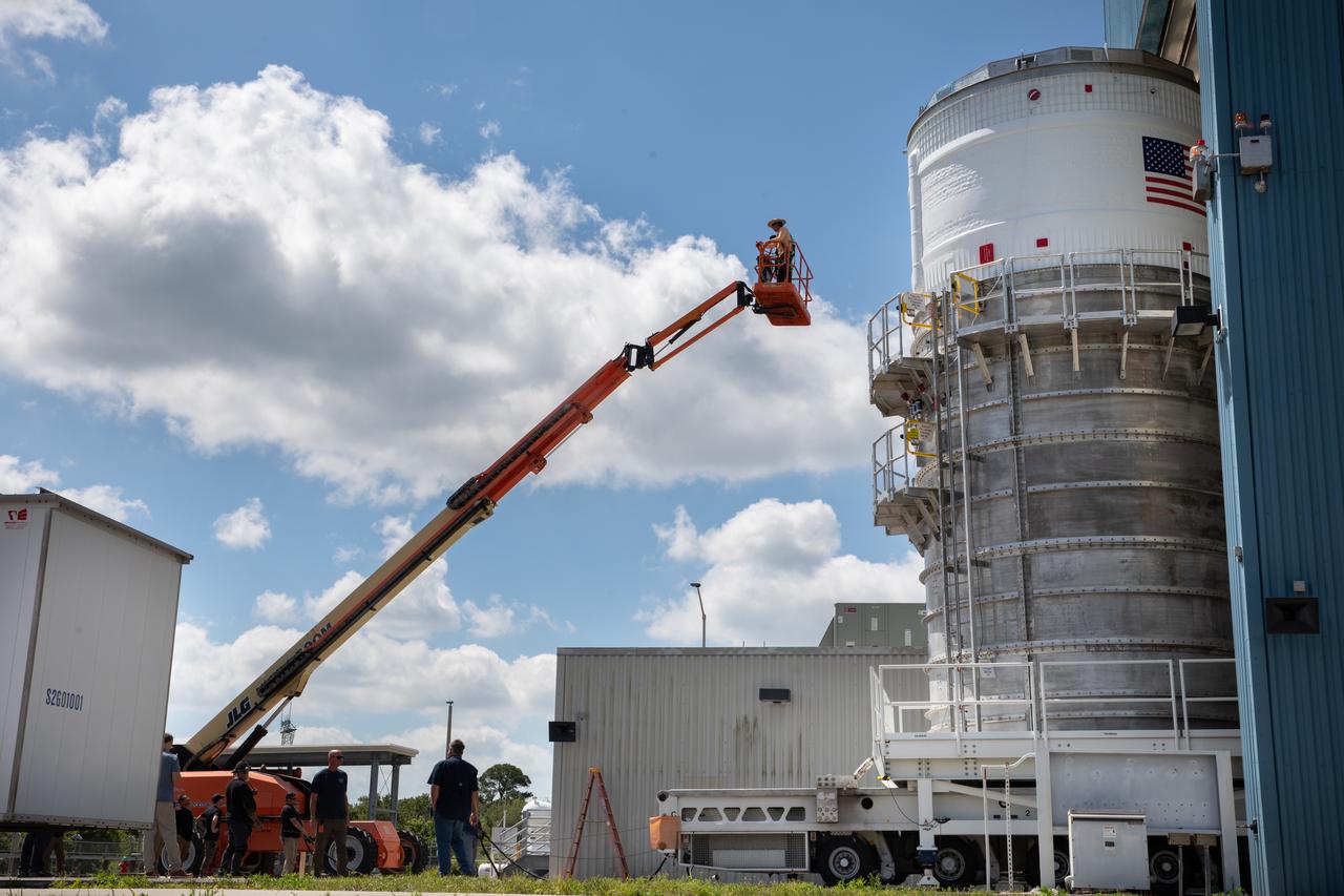
Teams with NASA’s Exploration Ground Systems Program transport the upper stage for the agency’s Artemis II SLS (Space Launch System) rocket from the Multi-Payload Processing Facility (MPPF) at NASA’s Kennedy Space Center in Florida to the spaceport’s Vehicle Assembly Building on Wednesday, April 16, 2025. Technicians fueled the SLS upper stage, known as the interim cryogenic propulsion stage, with hydrazine for its reaction control system at the MPPF and will now integrate the four-story propulsion system with SLS rocket elements atop mobile launcher 1.
Teams with NASA’s Exploration Ground Systems Program transport the upper stage for the agency’s Artemis II SLS (Space Launch System) rocket from the Multi-Payload Processing Facility (MPPF) at NASA’s Kennedy Space Center in Florida to the spaceport’s Vehicle Assembly Building on Wednesday, April 16, 2025. Technicians fueled the SLS upper stage, known as the interim cryogenic propulsion stage, with hydrazine for its reaction control system at the MPPF and will now integrate the four-story propulsion system with SLS rocket elements atop mobile launcher 1.
Teams with NASA’s Exploration Ground Systems Program transport the upper stage for the agency’s Artemis II SLS (Space Launch System) rocket from the Multi-Payload Processing Facility (MPPF) at NASA’s Kennedy Space Center in Florida to the spaceport’s Vehicle Assembly Building on Wednesday, April 16, 2025. Technicians fueled the SLS upper stage, known as the interim cryogenic propulsion stage, with hydrazine for its reaction control system at the MPPF and will now integrate the four-story propulsion system with SLS rocket elements atop mobile launcher 1.
Teams with NASA’s Exploration Ground Systems Program transport the upper stage for the agency’s Artemis II SLS (Space Launch System) rocket from the Multi-Payload Processing Facility (MPPF) at NASA’s Kennedy Space Center in Florida to the spaceport’s Vehicle Assembly Building on Wednesday, April 16, 2025. Technicians fueled the SLS upper stage, known as the interim cryogenic propulsion stage, with hydrazine for its reaction control system at the MPPF and will now integrate the four-story propulsion system with SLS rocket elements atop mobile launcher 1.
Teams with NASA’s Exploration Ground Systems Program transport the upper stage for the agency’s Artemis II SLS (Space Launch System) rocket from the Multi-Payload Processing Facility (MPPF) at NASA’s Kennedy Space Center in Florida to the spaceport’s Vehicle Assembly Building on Wednesday, April 16, 2025. Technicians fueled the SLS upper stage, known as the interim cryogenic propulsion stage, with hydrazine for its reaction control system at the MPPF and will now integrate the four-story propulsion system with SLS rocket elements atop mobile launcher 1.
Teams with NASA’s Exploration Ground Systems Program transport the upper stage for the agency’s Artemis II SLS (Space Launch System) rocket from the Multi-Payload Processing Facility (MPPF) at NASA’s Kennedy Space Center in Florida to the spaceport’s Vehicle Assembly Building on Wednesday, April 16, 2025. Technicians fueled the SLS upper stage, known as the interim cryogenic propulsion stage, with hydrazine for its reaction control system at the MPPF and will now integrate the four-story propulsion system with SLS rocket elements atop mobile launcher 1.
Teams with NASA’s Exploration Ground Systems Program transport the upper stage for the agency’s Artemis II SLS (Space Launch System) rocket from the Multi-Payload Processing Facility (MPPF) at NASA’s Kennedy Space Center in Florida to the spaceport’s Vehicle Assembly Building on Wednesday, April 16, 2025. Technicians fueled the SLS upper stage, known as the interim cryogenic propulsion stage, with hydrazine for its reaction control system at the MPPF and will now integrate the four-story propulsion system with SLS rocket elements atop mobile launcher 1.
Teams with NASA’s Exploration Ground Systems Program transport the upper stage for the agency’s Artemis II SLS (Space Launch System) rocket from the Multi-Payload Processing Facility (MPPF) at NASA’s Kennedy Space Center in Florida to the spaceport’s Vehicle Assembly Building on Wednesday, April 16, 2025. Technicians fueled the SLS upper stage, known as the interim cryogenic propulsion stage, with hydrazine for its reaction control system at the MPPF and will now integrate the four-story propulsion system with SLS rocket elements atop mobile launcher 1.
Teams with NASA’s Exploration Ground Systems Program transport the upper stage for the agency’s Artemis II SLS (Space Launch System) rocket from the Multi-Payload Processing Facility (MPPF) at NASA’s Kennedy Space Center in Florida to the spaceport’s Vehicle Assembly Building on Wednesday, April 16, 2025. Technicians fueled the SLS upper stage, known as the interim cryogenic propulsion stage, with hydrazine for its reaction control system at the MPPF and will now integrate the four-story propulsion system with SLS rocket elements atop mobile launcher 1.
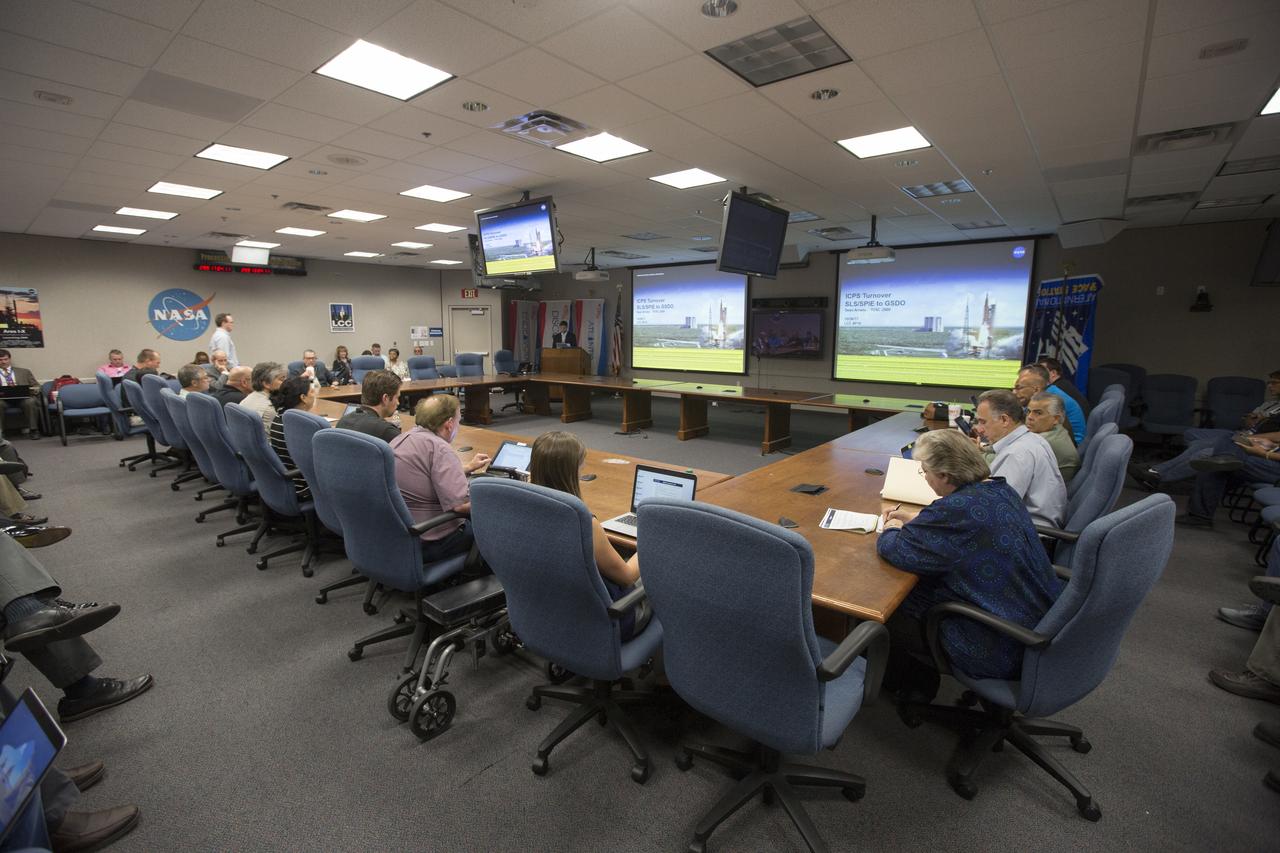
Meeting in the Launch Control Center of NASA's Kennedy Space Center in Florida, officials of the agency's Spacecraft/Payload Integration and Evolution (SPIE) organization formally turn over processing of the Space Launch System (SLS) rocket's Interim Cryogenic Propulsion Stage (ICPS) to the center's Ground Systems Development and Operations (GSDO) directorate. The ICPS is the first integrated piece of flight hardware to arrive in preparation for the uncrewed Exploration Mission-1. With the Orion attached, the ICPS sits atop the SLS rocket and will provide the spacecraft with the additional thrust needed to travel tens of thousands of miles beyond the Moon.
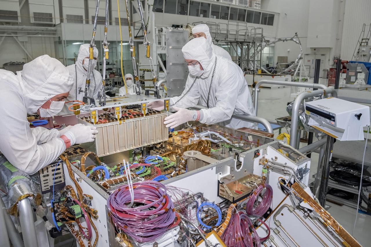
Engineers and technicians at NASA's Jet Propulsion Laboratory in Pasadena, California, integrate the rover motor controller assembly (RMCA) into the Mars 2020 rover's body. The RMCA is the electrical heart of the rover's mobility and motion systems, commanding and regulating the movement of the motors in the rover's wheels, robotic arms, mast, drill and sample-handling functions. The image was taken on April 29, 2019, in the Spacecraft Assembly Facility's High Bay 1 clean room at JPL. https://photojournal.jpl.nasa.gov/catalog/PIA23194
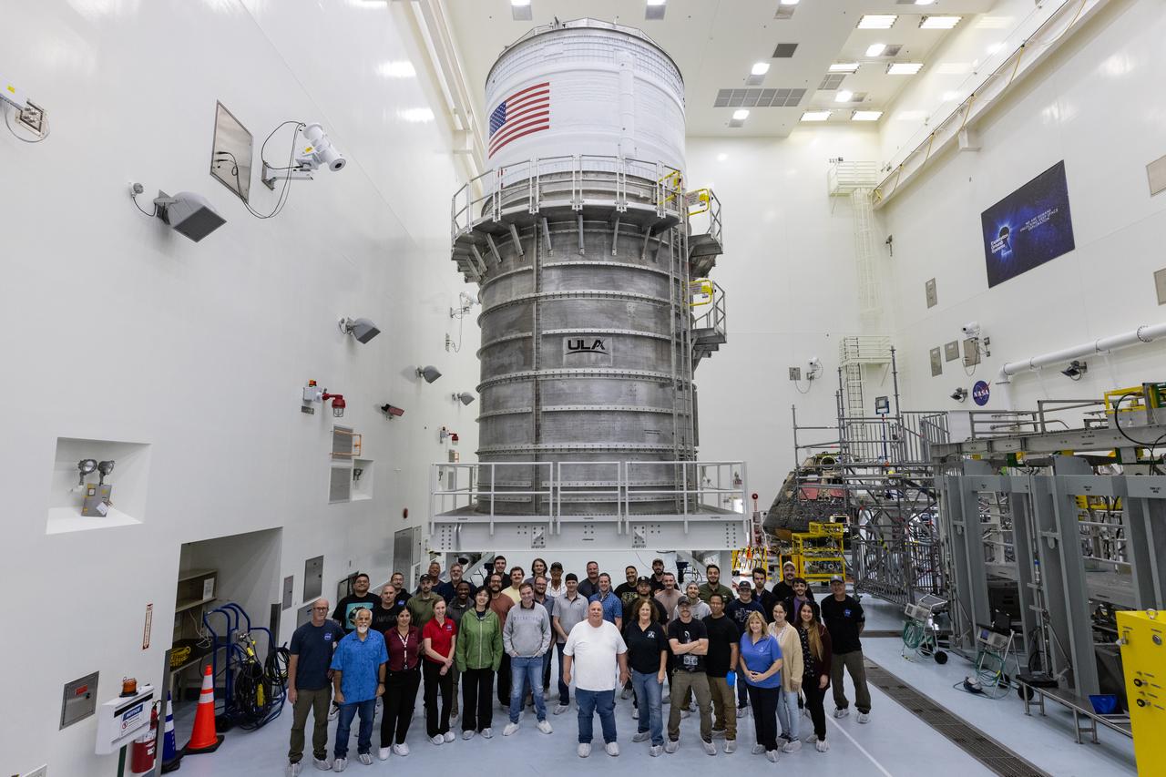
Teams with NASA’s Exploration Ground Systems Program pose for a photo in front of the upper stage for the agency’s Artemis II SLS (Space Launch System) rocket inside the Multi-Payload Processing Facility (MPPF) at NASA’s Kennedy Space Center in Florida on Wednesday, April 16, 2025. Visible in the background is also the Artemis I Orion crew module, now known as the Orion Environmental Test Article (ETA). Technicians fueled the SLS upper stage, known as the interim cryogenic propulsion stage, with hydrazine for its reaction control system at the MPPF before its transportation to the spaceport’s Vehicle Assembly Building and will now integrate the four-story propulsion system with SLS rocket elements atop mobile launcher 1.
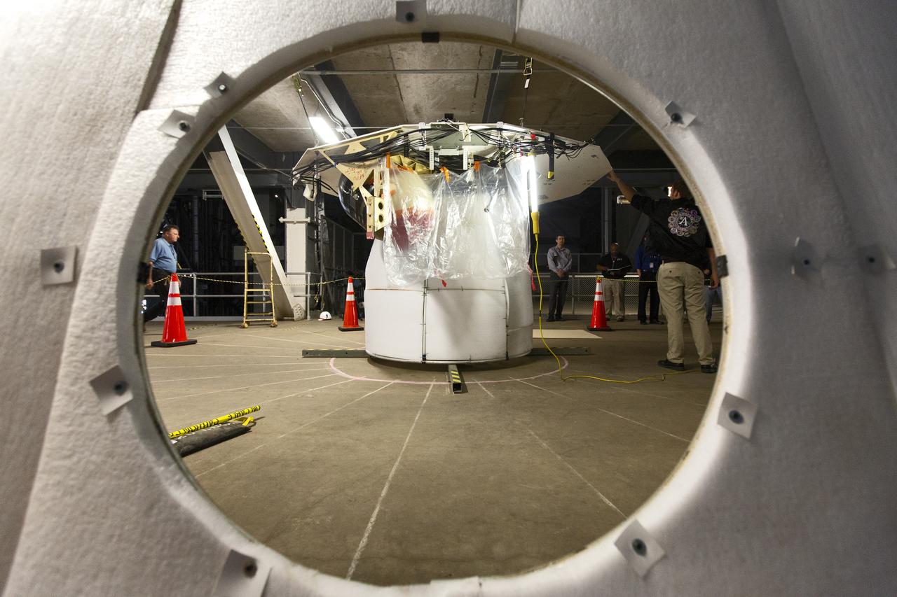
Robert Cook, a launch vehicle engineer with Millennium Engineering and Integration, talks during the Space Launch System (SLS) avionics handling tool demonstration inside Kennedy Space Center’s Vehicle Assembly Building on April 4, 2019. The demonstration showed that avionics boxes could be successfully and safely mounted into the SLS rocket’s upper stage — called the Interim Cryogenic Propulsion Stage, or ICPS — with low risk of damaging a closely located hydrazine tank. Avionics boxes include the Inertial Navigation and Control Assembly and flight batteries. Cook designed the ICPS section mockup used in the exercise.
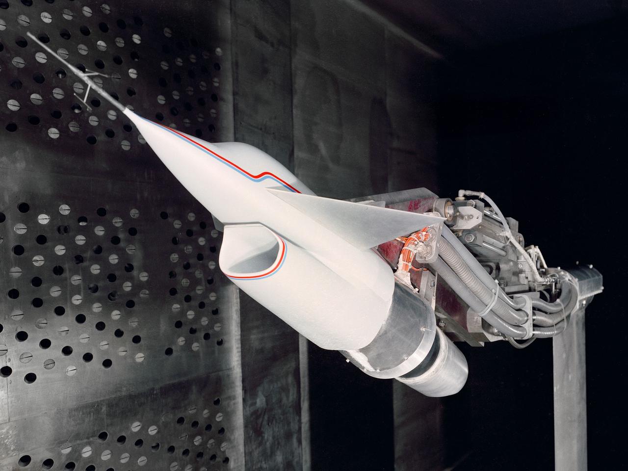
A Highly Maneuverable Aircraft Technology (HiMAT) inlet model installed in the test section of the 8- by 6-Foot Supersonic Wind Tunnel at the National Aeronautics and Space Administration (NASA) Lewis Research Center. Engineers at the Ames Research Center, Dryden Flight Research Center, and Rockwell International designed two pilotless subscale HiMAT vehicles in the mid-1970s to study new design concepts for fighter aircraft in the transonic realm without risking the lives of test pilots. The aircraft used sophisticated technologies such as advanced aerodynamics, composite materials, digital integrated propulsion control, and digital fly-by-wire control systems. In late 1977 NASA Lewis studied the HiMAT’s General Electric J85-21 jet engine in the Propulsion Systems Laboratory. The researchers charted the inlet quality with various combinations anti-distortion screens. HiMAT employed a relatively short and curved inlet compared to actual fighter jets. In the spring of 1979, Larry Smith led an in-depth analysis of the HiMAT inlet in the 8- by 6 tunnel. The researchers installed vortex generators to battle flow separation in the diffuser. The two HiMAT aircraft performed 11 hours of flying over the course of 26 missions from mid-1979 to January 1983 at Dryden and Ames. Although the HiMAT vehicles were considered to be overly complex and expensive, the program yielded a wealth of data that would validate computer-based design tools.
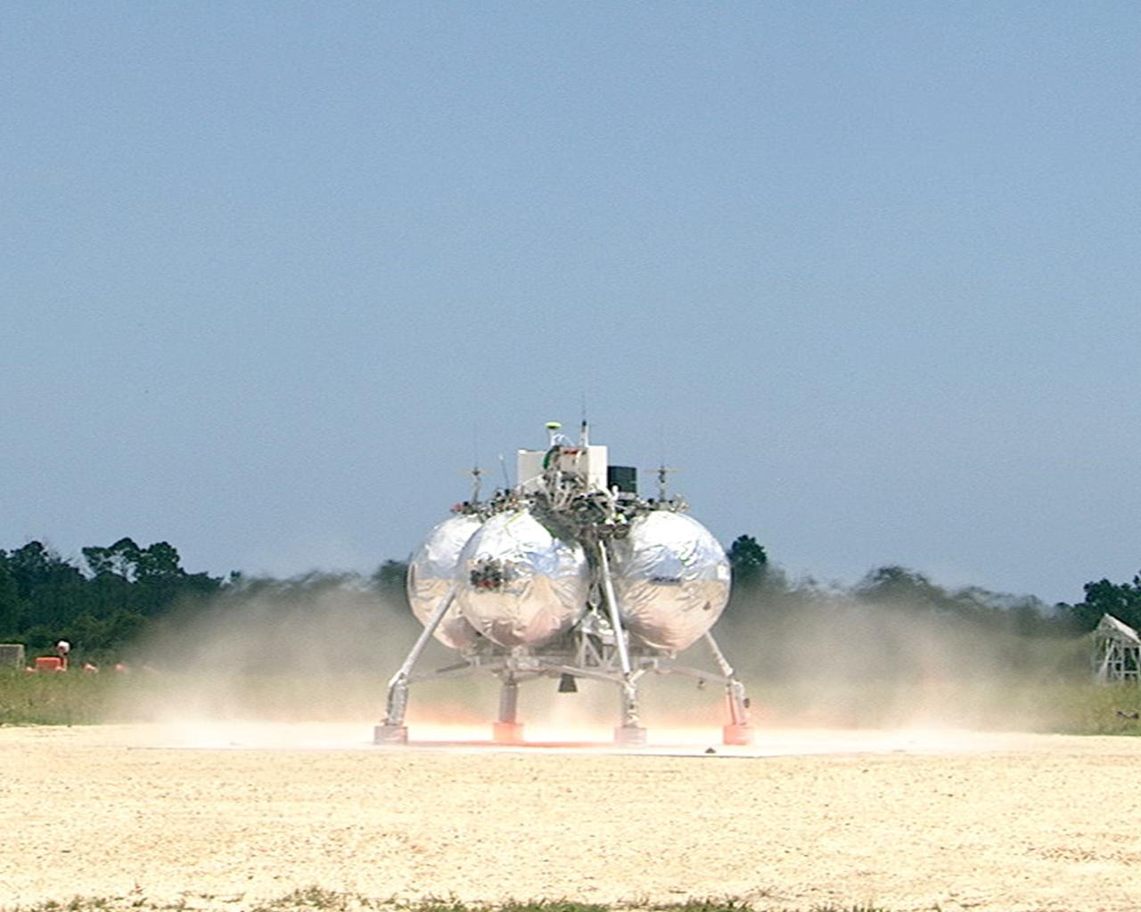
CAPE CANAVERAL, Fla. – At the Shuttle Landing Facility at NASA’s Kennedy Space Center in Florida, the Morpheus prototype lander begins to lift off of the ground during a free-flight test. Testing of the prototype lander had been ongoing at NASA’s Johnson Space Center in Houston in preparation for its first free-flight test at Kennedy Space Center. Morpheus was manufactured and assembled at JSC and Armadillo Aerospace. Morpheus is large enough to carry 1,100 pounds of cargo to the moon – for example, a humanoid robot, a small rover, or a small laboratory to convert moon dust into oxygen. The primary focus of the test is to demonstrate an integrated propulsion and guidance, navigation and control system that can fly a lunar descent profile to exercise the Autonomous Landing and Hazard Avoidance Technology, or ALHAT, safe landing sensors and closed-loop flight control. For more information on Project Morpheus, visit http://morpheuslander.jsc.nasa.gov/. Photo credit: NASA
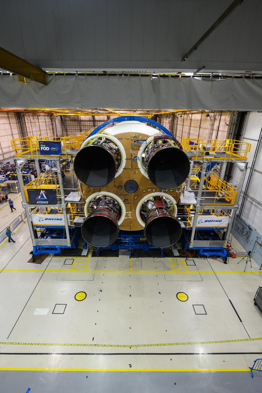
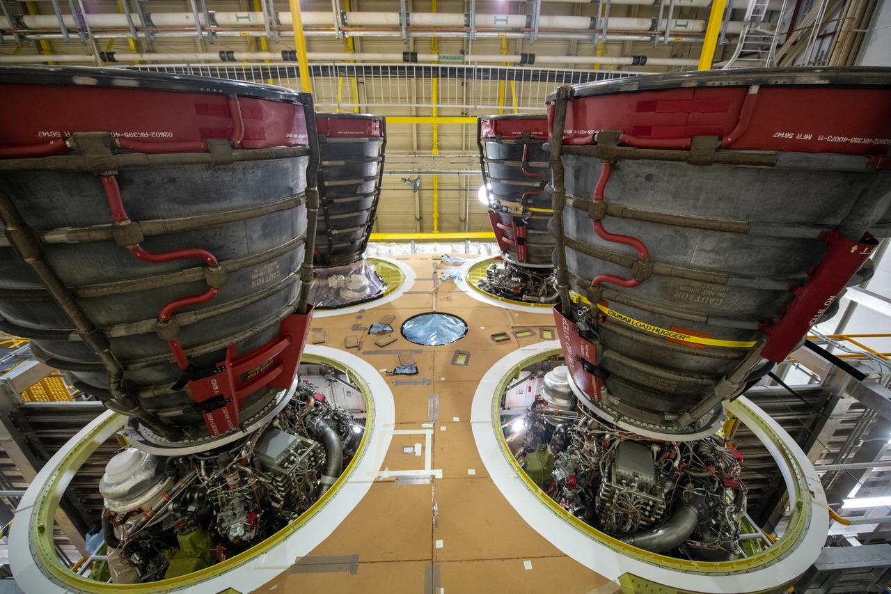
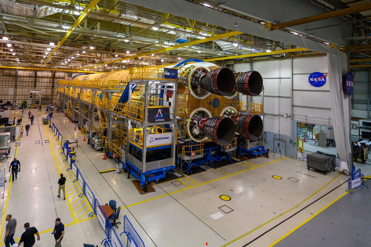
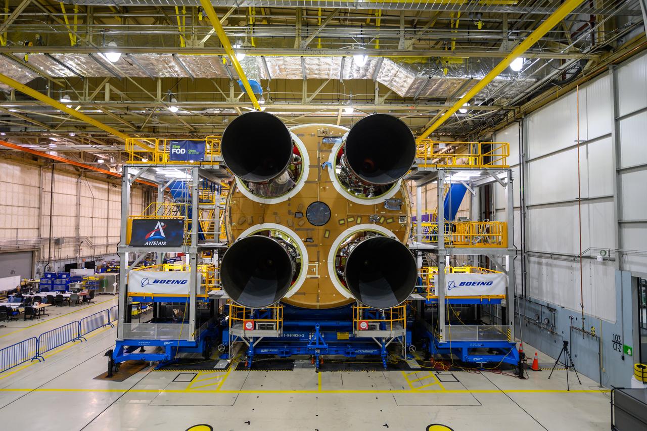
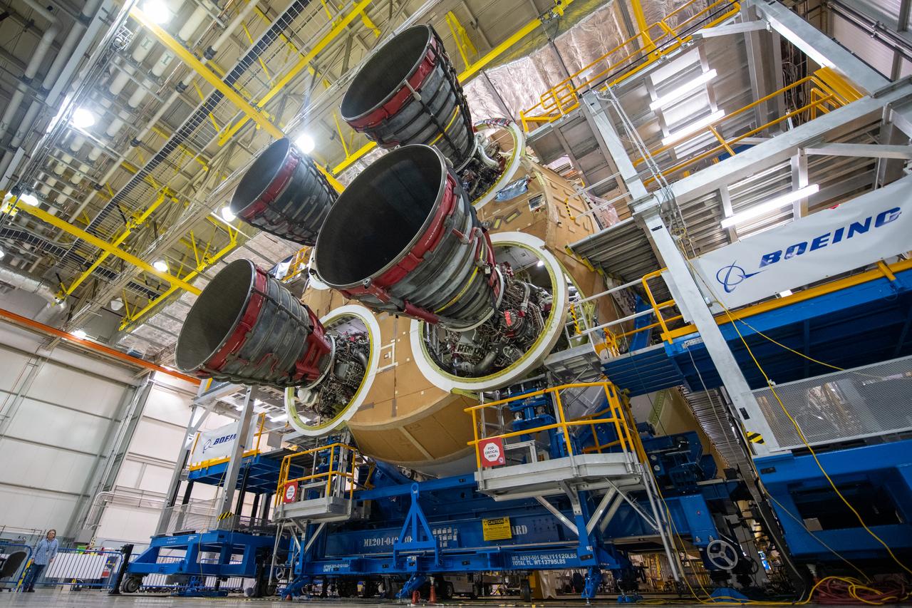
This photo shows all four RS-25 engines attached to the core stage for NASA’s Space Launch System rocket for the agency’s Artemis I mission to the Moon. To complete assembly of the rocket stage, engineers and technicians at NASA’s Michoud Assembly Facility in New Orleans are now integrating the propulsion and electrical systems within the structure. The completed core stage with all four RS-25 engines attached is the largest rocket stage NASA has built since the Saturn V stages for the Apollo Program that first sent Americans to the Moon. The stage, which includes two propellant tanks, provides more than 2 million pounds of thrust to send Artemis I to the Moon. Engineers and technicians attached the fourth RS-25 engine to the rocket stage Nov. 6 just one day after structurally mating the third engine. The first two RS-25 engines were structurally mated to the stage in October. After assembly is complete, crews will conduct an integrated functional test of flight computers, avionics and electrical systems that run throughout the 212-foot-tall core stage in preparation for its completion later this year. This testing is the first time all the flight avionics systems will be tested together to ensure the systems communicate with each other and will perform properly to control the rocket’s flight. Integration of the RS-25 engines to the recently completed core stage structure is a collaborative, multistep process for NASA and its partners Boeing, the core stage lead contractor, and Aerojet Rocketdyne, the RS-25 engines lead contractor. Offering more payload mass, volume capability and energy to speed missions through space, the SLS rocket, along with NASA’s Gateway in lunar orbit and Orion, is part of NASA’s backbone for deep space exploration and the Artemis lunar program. No other rocket is capable of carrying astronauts in Orion around the Moon in a single mission.
This photo shows all four RS-25 engines attached to the core stage for NASA’s Space Launch System rocket for the agency’s Artemis I mission to the Moon. To complete assembly of the rocket stage, engineers and technicians at NASA’s Michoud Assembly Facility in New Orleans are now integrating the propulsion and electrical systems within the structure. The completed core stage with all four RS-25 engines attached is the largest rocket stage NASA has built since the Saturn V stages for the Apollo Program that first sent Americans to the Moon. The stage, which includes two propellant tanks, provides more than 2 million pounds of thrust to send Artemis I to the Moon. Engineers and technicians attached the fourth RS-25 engine to the rocket stage Nov. 6 just one day after structurally mating the third engine. The first two RS-25 engines were structurally mated to the stage in October. After assembly is complete, crews will conduct an integrated functional test of flight computers, avionics and electrical systems that run throughout the 212-foot-tall core stage in preparation for its completion later this year. This testing is the first time all the flight avionics systems will be tested together to ensure the systems communicate with each other and will perform properly to control the rocket’s flight. Integration of the RS-25 engines to the recently completed core stage structure is a collaborative, multistep process for NASA and its partners Boeing, the core stage lead contractor, and Aerojet Rocketdyne, the RS-25 engines lead contractor. Offering more payload mass, volume capability and energy to speed missions through space, the SLS rocket, along with NASA’s Gateway in lunar orbit and Orion, is part of NASA’s backbone for deep space exploration and the Artemis lunar program. No other rocket is capable of carrying astronauts in Orion around the Moon in a single mission.
This photo shows all four RS-25 engines attached to the core stage for NASA’s Space Launch System rocket for the agency’s Artemis I mission to the Moon. To complete assembly of the rocket stage, engineers and technicians at NASA’s Michoud Assembly Facility in New Orleans are now integrating the propulsion and electrical systems within the structure. The completed core stage with all four RS-25 engines attached is the largest rocket stage NASA has built since the Saturn V stages for the Apollo Program that first sent Americans to the Moon. The stage, which includes two propellant tanks, provides more than 2 million pounds of thrust to send Artemis I to the Moon. Engineers and technicians attached the fourth RS-25 engine to the rocket stage Nov. 6 just one day after structurally mating the third engine. The first two RS-25 engines were structurally mated to the stage in October. After assembly is complete, crews will conduct an integrated functional test of flight computers, avionics and electrical systems that run throughout the 212-foot-tall core stage in preparation for its completion later this year. This testing is the first time all the flight avionics systems will be tested together to ensure the systems communicate with each other and will perform properly to control the rocket’s flight. Integration of the RS-25 engines to the recently completed core stage structure is a collaborative, multistep process for NASA and its partners Boeing, the core stage lead contractor, and Aerojet Rocketdyne, the RS-25 engines lead contractor. Offering more payload mass, volume capability and energy to speed missions through space, the SLS rocket, along with NASA’s Gateway in lunar orbit and Orion, is part of NASA’s backbone for deep space exploration and the Artemis lunar program. No other rocket is capable of carrying astronauts in Orion around the Moon in a single mission.
This photo shows all four RS-25 engines attached to the core stage for NASA’s Space Launch System rocket for the agency’s Artemis I mission to the Moon. To complete assembly of the rocket stage, engineers and technicians at NASA’s Michoud Assembly Facility in New Orleans are now integrating the propulsion and electrical systems within the structure. The completed core stage with all four RS-25 engines attached is the largest rocket stage NASA has built since the Saturn V stages for the Apollo Program that first sent Americans to the Moon. The stage, which includes two propellant tanks, provides more than 2 million pounds of thrust to send Artemis I to the Moon. Engineers and technicians attached the fourth RS-25 engine to the rocket stage Nov. 6 just one day after structurally mating the third engine. The first two RS-25 engines were structurally mated to the stage in October. After assembly is complete, crews will conduct an integrated functional test of flight computers, avionics and electrical systems that run throughout the 212-foot-tall core stage in preparation for its completion later this year. This testing is the first time all the flight avionics systems will be tested together to ensure the systems communicate with each other and will perform properly to control the rocket’s flight. Integration of the RS-25 engines to the recently completed core stage structure is a collaborative, multistep process for NASA and its partners Boeing, the core stage lead contractor, and Aerojet Rocketdyne, the RS-25 engines lead contractor. Offering more payload mass, volume capability and energy to speed missions through space, the SLS rocket, along with NASA’s Gateway in lunar orbit and Orion, is part of NASA’s backbone for deep space exploration and the Artemis lunar program. No other rocket is capable of carrying astronauts in Orion around the Moon in a single mission.
This photo shows all four RS-25 engines attached to the core stage for NASA’s Space Launch System rocket for the agency’s Artemis I mission to the Moon. To complete assembly of the rocket stage, engineers and technicians at NASA’s Michoud Assembly Facility in New Orleans are now integrating the propulsion and electrical systems within the structure. The completed core stage with all four RS-25 engines attached is the largest rocket stage NASA has built since the Saturn V stages for the Apollo Program that first sent Americans to the Moon. The stage, which includes two propellant tanks, provides more than 2 million pounds of thrust to send Artemis I to the Moon. Engineers and technicians attached the fourth RS-25 engine to the rocket stage Nov. 6 just one day after structurally mating the third engine. The first two RS-25 engines were structurally mated to the stage in October. After assembly is complete, crews will conduct an integrated functional test of flight computers, avionics and electrical systems that run throughout the 212-foot-tall core stage in preparation for its completion later this year. This testing is the first time all the flight avionics systems will be tested together to ensure the systems communicate with each other and will perform properly to control the rocket’s flight. Integration of the RS-25 engines to the recently completed core stage structure is a collaborative, multistep process for NASA and its partners Boeing, the core stage lead contractor, and Aerojet Rocketdyne, the RS-25 engines lead contractor. Offering more payload mass, volume capability and energy to speed missions through space, the SLS rocket, along with NASA’s Gateway in lunar orbit and Orion, is part of NASA’s backbone for deep space exploration and the Artemis lunar program. No other rocket is capable of carrying astronauts in Orion around the Moon in a single mission.

Launch team members are seated at the Main Propulsion System consoles inside Firing Room 1 of the Launch Control Center at NASA’s Kennedy Space Center in Florida on Dec. 13, 2021. They are participating in a joint integrated simulation for the Artemis I launch that covered both cryogenic loading and terminal countdown portions of prelaunch activities. Members of NASA’s mission management team and launch team conducted the simulation together. The Kennedy team was certified for the Artemis I launch. During Artemis I, the agency’s Orion spacecraft will lift off from Kennedy aboard NASA’s most powerful rocket – the Space Launch System – to fly farther than any spacecraft built for humans has ever flown. Through NASA’s Artemis missions, the agency, along with commercial and international partners, will establish a sustainable human presence on the Moon to prepare for missions to Mars.
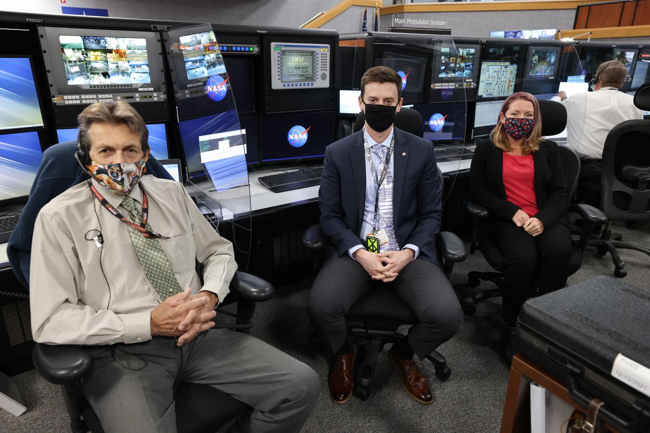
Launch team members are seated at the Main Propulsion System consoles inside Firing Room 1 of the Launch Control Center at NASA’s Kennedy Space Center in Florida on Dec. 13, 2021. They are participating in a joint integrated simulation for the Artemis I launch that covered both cryogenic loading and terminal countdown portions of prelaunch activities. Members of NASA’s mission management team and launch team conducted the simulation together. The Kennedy team was certified for the Artemis I launch. During Artemis I, the agency’s Orion spacecraft will lift off from Kennedy aboard NASA’s most powerful rocket – the Space Launch System – to fly farther than any spacecraft built for humans has ever flown. Through NASA’s Artemis missions, the agency, along with commercial and international partners, will establish a sustainable human presence on the Moon to prepare for missions to Mars.
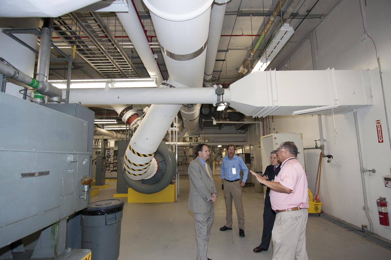
CAPE CANAVERAL, Fla. – NASA Associate Administrator Robert Lightfoot tours the Environmental Control System Room under the surface of Launch Pad 39B during a visit to NASA's Kennedy Space Center in Florida. From left are Lightfoot, Alan Littlefield, Vehicle Integration and Launch chief engineer, Kennedy Director Bob Cabana, and Jose Perez Morales, launch pad project manager. The pad is being modified to support NASA's new Orion spacecraft and Space Launch System heavy-lift rocket, the SLS. NASA's FY2014 budget proposal includes a plan to robotically capture a small near-Earth asteroid and redirect it safely to a stable orbit in the Earth-moon system where astronauts can visit and explore it. Performing these elements for the proposed asteroid initiative integrates the best of NASA's science, technology and human exploration capabilities and draws on the innovation of America's brightest scientists and engineers. It uses current and developing capabilities to find both large asteroids that pose a hazard to Earth and small asteroids that could be candidates for the initiative, accelerates our technology development activities in high-powered solar electric propulsion and takes advantage of our hard work on the Space Launch System rocket and Orion spacecraft, helping to keep NASA on target to reach the President's goal of sending humans to Mars in the 2030s. Photo credit: NASA_Jim Grossmann
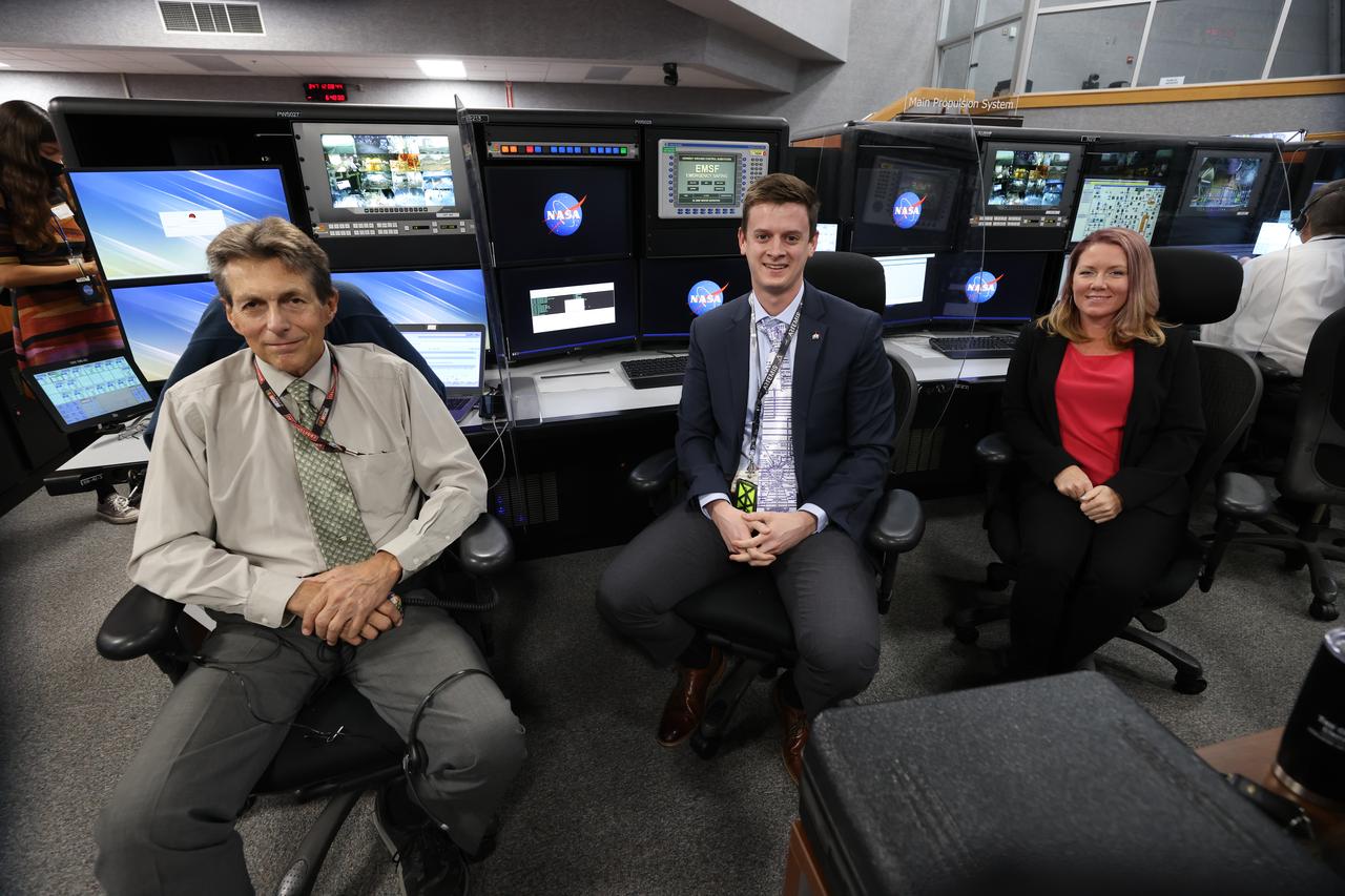
Launch team members are seated at the Main Propulsion consoles inside Firing Room 1 of the Launch Control Center at NASA’s Kennedy Space Center in Florida on Dec. 13, 2021. They are participating in a joint integrated simulation for the Artemis I launch that covered both cryogenic loading and terminal countdown portions of prelaunch activities. Members of NASA’s mission management team and launch team conducted the simulation together. The Kennedy team was certified for the Artemis I launch. During Artemis I, the agency’s Orion spacecraft will lift off from Kennedy aboard NASA’s most powerful rocket – the Space Launch System – to fly farther than any spacecraft built for humans has ever flown. Through NASA’s Artemis missions, the agency, along with commercial and international partners, will establish a sustainable human presence on the Moon to prepare for missions to Mars.
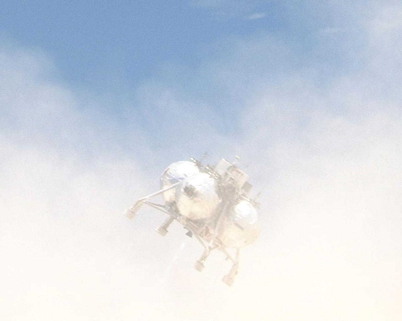
CAPE CANAVERAL, Fla. – During a free-flight test of the Project Morpheus vehicle at the Shuttle Landing Facility at NASA’s Kennedy Space Center in Florida, the vehicle lifted off the ground and then experienced a hardware component failure, which prevented it from maintaining stable flight. Engineers are looking into the test data and the agency will release information as it becomes available. Failures such as these were anticipated prior to the test, and are part of the development process for any complex spaceflight hardware. Testing of the prototype lander had been ongoing at NASA’s Johnson Space Center in Houston in preparation for its first free-flight test at Kennedy Space Center. Morpheus was manufactured and assembled at JSC and Armadillo Aerospace. Morpheus is large enough to carry 1,100 pounds of cargo to the moon – for example, a humanoid robot, a small rover, or a small laboratory to convert moon dust into oxygen. The primary focus of the test is to demonstrate an integrated propulsion and guidance, navigation and control system that can fly a lunar descent profile to exercise the Autonomous Landing and Hazard Avoidance Technology, or ALHAT, safe landing sensors and closed-loop flight control. For more information on Project Morpheus, visit http://morpheuslander.jsc.nasa.gov/. Photo credit: NASA
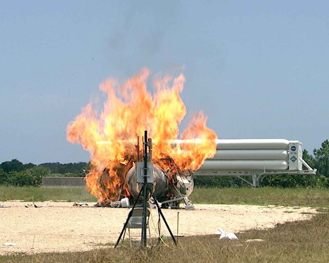
CAPE CANAVERAL, Fla. – During a free-flight test of the Project Morpheus vehicle at the Shuttle Landing Facility at NASA’s Kennedy Space Center in Florida, the vehicle lifted off the ground and then experienced a hardware component failure, which prevented it from maintaining stable flight. No one was injured and the resulting fire was extinguished by Kennedy fire personnel. Engineers are looking into the test data and the agency will release information as it becomes available. Failures such as these were anticipated prior to the test, and are part of the development process for any complex spaceflight hardware. Testing of the prototype lander had been ongoing at NASA’s Johnson Space Center in Houston in preparation for its first free-flight test at Kennedy Space Center. Morpheus was manufactured and assembled at JSC and Armadillo Aerospace. Morpheus is large enough to carry 1,100 pounds of cargo to the moon – for example, a humanoid robot, a small rover, or a small laboratory to convert moon dust into oxygen. The primary focus of the test is to demonstrate an integrated propulsion and guidance, navigation and control system that can fly a lunar descent profile to exercise the Autonomous Landing and Hazard Avoidance Technology, or ALHAT, safe landing sensors and closed-loop flight control. For more information on Project Morpheus, visit http://morpheuslander.jsc.nasa.gov/. Photo credit: NASA
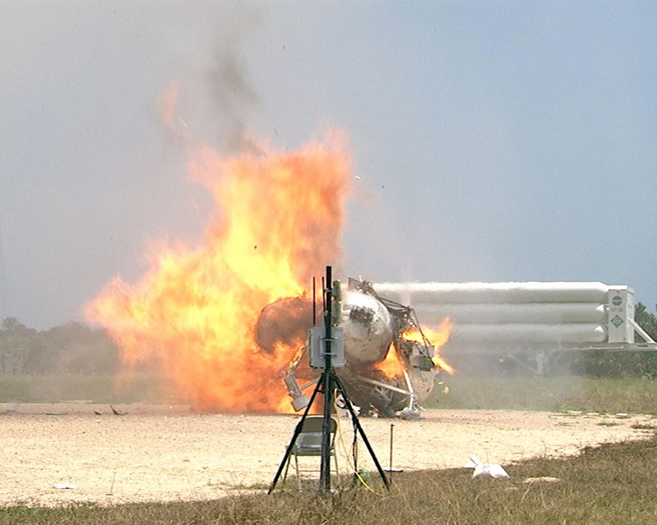
CAPE CANAVERAL, Fla. – During a free-flight test of the Project Morpheus vehicle at the Shuttle Landing Facility at NASA’s Kennedy Space Center in Florida, the vehicle lifted off the ground and then experienced a hardware component failure, which prevented it from maintaining stable flight. No one was injured and the resulting fire was extinguished by Kennedy fire personnel. Engineers are looking into the test data and the agency will release information as it becomes available. Failures such as these were anticipated prior to the test, and are part of the development process for any complex spaceflight hardware. Testing of the prototype lander had been ongoing at NASA’s Johnson Space Center in Houston in preparation for its first free-flight test at Kennedy Space Center. Morpheus was manufactured and assembled at JSC and Armadillo Aerospace. Morpheus is large enough to carry 1,100 pounds of cargo to the moon – for example, a humanoid robot, a small rover, or a small laboratory to convert moon dust into oxygen. The primary focus of the test is to demonstrate an integrated propulsion and guidance, navigation and control system that can fly a lunar descent profile to exercise the Autonomous Landing and Hazard Avoidance Technology, or ALHAT, safe landing sensors and closed-loop flight control. For more information on Project Morpheus, visit http://morpheuslander.jsc.nasa.gov/. Photo credit: NASA
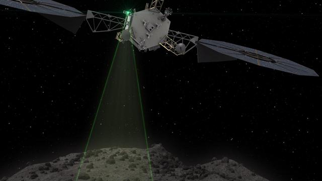
This graphic depicts the Asteroid Redirect Vehicle conducting a flyby of its target asteroid. During these flybys, the Asteroid Redirect Mission (ARM) would come within 0.6 miles (1 kilometer), generating imagery with resolution of up to 0.4 of an inch (1 centimeter) per pixel. The robotic segment of ARM will demonstrate advanced, high-power, high-throughput solar electric propulsion; advanced autonomous precision proximity operations at a low-gravity planetary body; and controlled touchdown and liftoff with a multi-ton mass. The crew segment of the mission will include spacewalk activities for sample selection, extraction, containment and return; and mission operations of integrated robotic and crewed vehicle stack -- all key components of future in-space operations for human missions to the Mars system. After collecting a multi-ton boulder from the asteroid, the robotic spacecraft will redirect the boulder to a crew-accessible orbit around the moon, where NASA plans to conduct a series of proving ground missions in the 2020s that will help validate capabilities needed for NASA's Journey to Mars. http://photojournal.jpl.nasa.gov/catalog/PIA21062
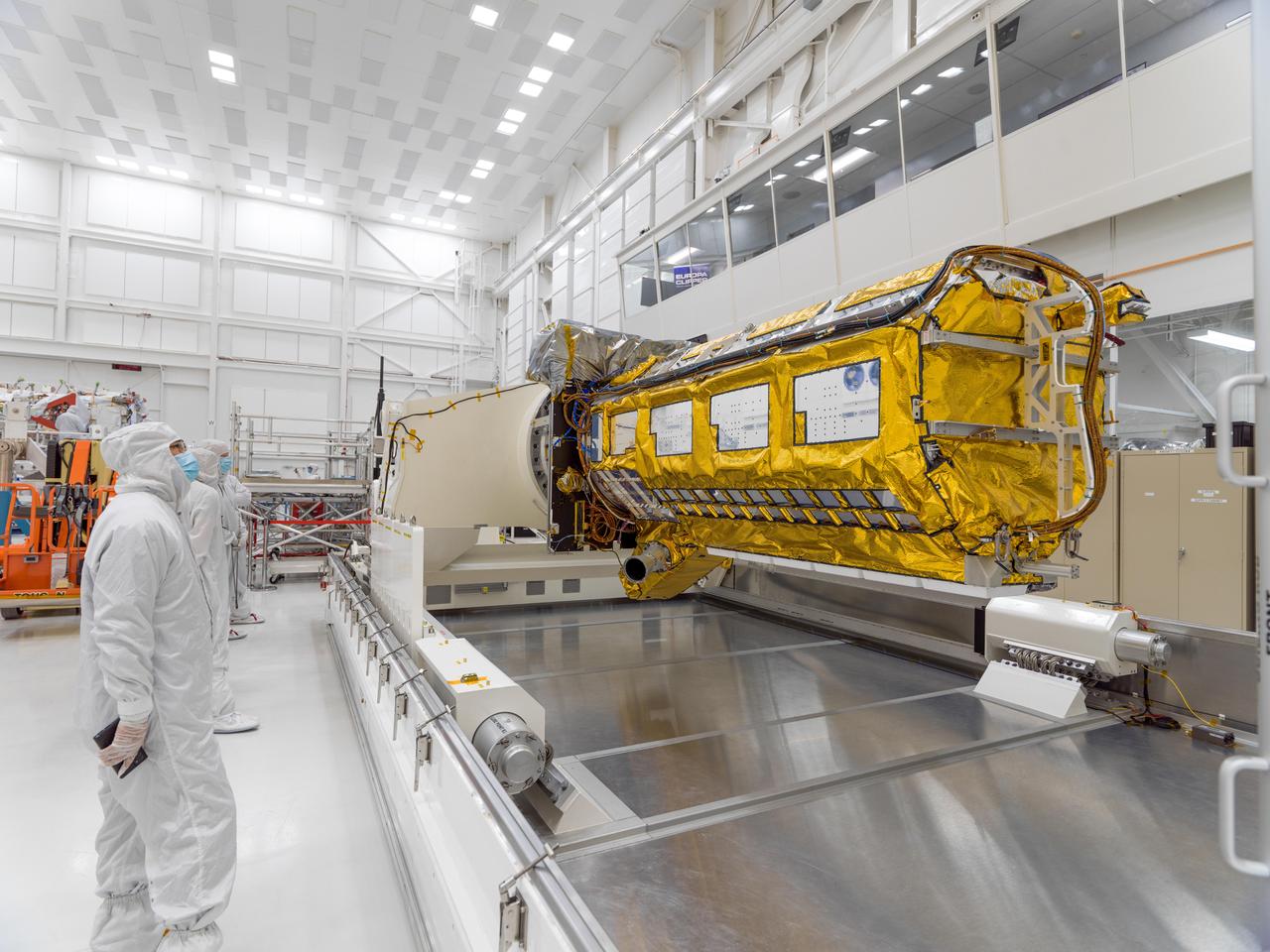
Members of the international Surface Water and Ocean Topography (SWOT) mission test one of the antennas for the Ka-band Radar Interferometer (KaRIn) instrument in a clean room at NASA's Jet Propulsion Laboratory in Southern California. The mission is a collaborative effort between NASA and the French space agency Centre National d'Études Spatiales (CNES) – with contributions from the Canadian Space Agency (CSA) and the UK Space Agency. KaRIn is the scientific heart of the SWOT satellite, which will survey the water on more than 90% of Earth's surface, measuring the height of water in lakes, rivers, reservoirs, and the ocean. To do that, KaRIn will transmit radar pulses to Earth's surface and use its two antennas to triangulate the return signals that bounce back. Mounted at the ends of a boom 33 feet (10 meters) long, the antennas will collect data along a swath 30 miles (50 kilometers) wide on either side of the satellite. KaRIn will operate in two modes: A lower-resolution mode over the ocean will involve significant onboard processing of the data to reduce the volume of information sent during downlinks to Earth; a higher-resolution mode will be used mainly over land. Scheduled to launch from Vandenberg Space Force Base in Central California on Dec. 15, 2022, SWOT is being jointly developed by NASA and CNES, with contributions from the CSA and the UK Space Agency. NASA's Jet Propulsion Laboratory, which is managed for the agency by Caltech in Pasadena, California, leads the U.S. component of the project. For the flight system payload, NASA is providing the Ka-band Radar Interferometer (KaRIn) instrument, a GPS science receiver, a laser retroreflector, a two-beam microwave radiometer, and NASA instrument operations. CNES is providing the Doppler Orbitography and Radioposition Integrated by Satellite (DORIS) system, the dual frequency Poseidon altimeter (developed by Thales Alenia Space), the KaRIn radio-frequency subsystem (together with Thales Alenia Space and with support from the UK Space Agency), the satellite platform, and ground control segment. CSA is providing the KaRIn high-power transmitter assembly. NASA is providing the launch vehicle and associated launch services. https://photojournal.jpl.nasa.gov/catalog/PIA25594
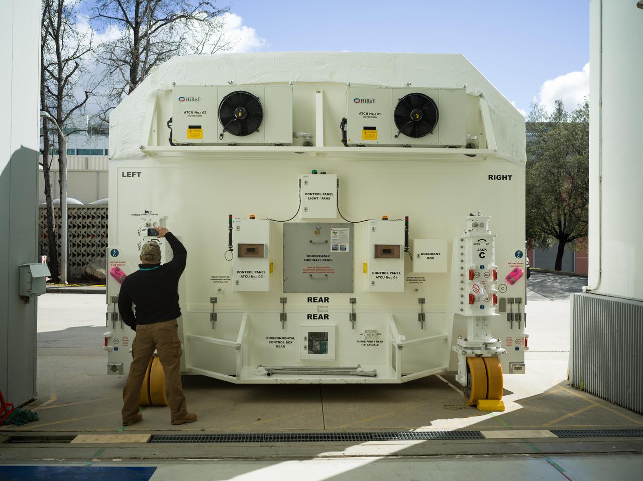
A specially designed, climate-controlled shipping container holding the NASA-ISRO Synthetic Aperture Radar (NISAR) science instrument payload sits outside an airlock at the Spacecraft Assembly Facility at NASA's Jet Propulsion Laboratory on Feb. 26, 2023. The payload was shipped to Bengaluru, India, on March 3, arriving on March 6. There it will be integrated with the satellite body, or bus, and undergo further testing leading up to launch in 2024. The NISAR mission – a joint effort between NASA and the Indian Space Research Organisation – will observe nearly all the planet's land and ice surfaces twice every 12 days, measuring movements in extremely fine detail. It will also survey forests and agricultural regions to understand carbon exchange between plants and the atmosphere. NISAR's science payload will be the most advanced radar system ever launched as part of a NASA mission, and it will feature the largest-ever radar antenna of its kind: a drum-shaped, wire mesh reflector nearly 40 feet (12 meters) in diameter that will extend from a 30-foot (9-meter) boom. The mission's science instruments consist of L- and S-band radar, so named to indicate the wavelengths of their signals. ISRO built the S-band radar, which it shipped to JPL in March 2021. Engineers spent much of the last two years integrating the instrument with the JPL-built L-band system, then conducting tests to verify they work well together. JPL, which is managed for NASA by Caltech in Pasadena, leads the U.S. component of NISAR. In addition to the L-band radar, NASA is also providing the radar reflector antenna, the deployable boom, a high-rate communication subsystem for science data, GPS receivers, a solid-state recorder, and payload data subsystem. In addition to the S-band radar, ISRO is providing the spacecraft bus, the launch vehicle, and associated launch services and satellite mission operations. https://photojournal.jpl.nasa.gov/catalog/PIA25568
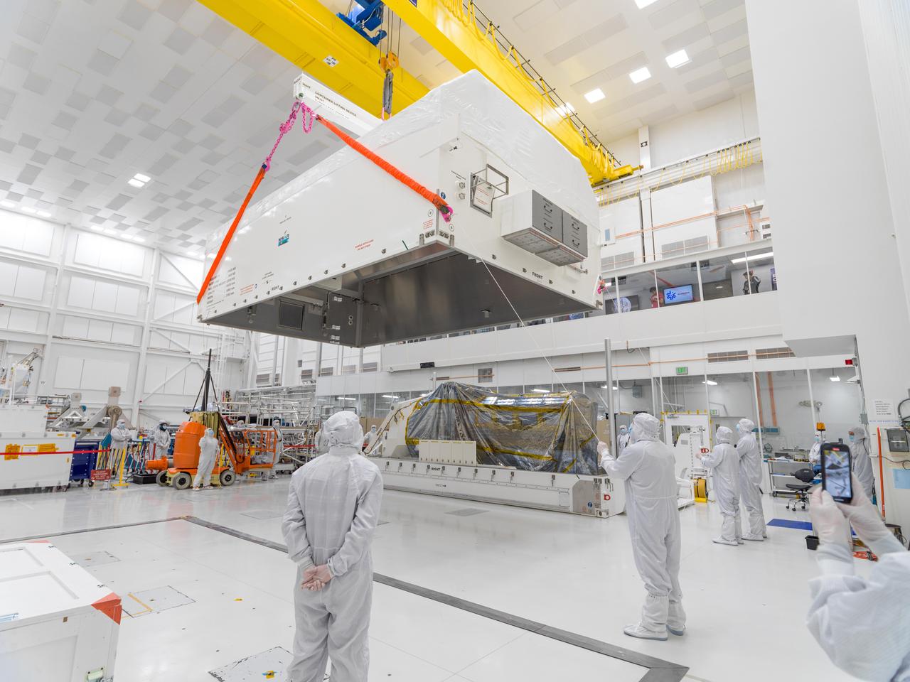
In a clean room at NASA's Jet Propulsion Laboratory on Feb. 23, 2023, engineers and technicians use a crane to prepare to seal a specially designed, climate-controlled shipping container holding the NASA-ISRO Synthetic Aperture Radar (NISAR) science instrument payload. The payload was then shipped to Bengaluru, India, on March 3, arriving on March 6. There it will be integrated with the satellite body, or bus, and undergo further testing leading up to launch in 2024. The NISAR mission – a joint effort between NASA and the Indian Space Research Organisation – will observe nearly all the planet's land and ice surfaces twice every 12 days, measuring movements in extremely fine detail. It will also survey forests and agricultural regions to understand carbon exchange between plants and the atmosphere. NISAR's science payload will be the most advanced radar system ever launched as part of a NASA mission, and it will feature the largest-ever radar antenna of its kind: a drum-shaped, wire mesh reflector nearly 40 feet (12 meters) in diameter that will extend from a 30-foot (9-meter) boom. The mission's science instruments consist of L- and S-band radar, so named to indicate the wavelengths of their signals. ISRO built the S-band radar, which it shipped to JPL in March 2021. Engineers spent much of the last two years integrating the instrument with the JPL-built L-band system, then conducting tests to verify they work well together. JPL, which is managed for NASA by Caltech in Pasadena, leads the U.S. component of NISAR. In addition to the L-band radar, NASA is also providing the radar reflector antenna, the deployable boom, a high-rate communication subsystem for science data, GPS receivers, a solid-state recorder, and payload data subsystem. In addition to the S-band radar, ISRO is providing the spacecraft bus, the launch vehicle, and associated launch services and satellite mission operations. https://photojournal.jpl.nasa.gov/catalog/PIA25567
The NASA-ISRO Synthetic Aperture Radar (NISAR) science instrument payload sits in its specially designed, climate-controlled shipping container in a clean room at NASA's Jet Propulsion Laboratory on Feb. 23, 2023. Engineers and technicians used a crane to lift the payload and mount it vertically onto a stage at the far end of the container before tilting it horizontally. The payload was then shipped to Bengaluru, India, on March 3, arriving on March 6. There it will be integrated with the satellite body, or bus, and undergo further testing leading up to launch in 2024. The NISAR mission – a joint effort between NASA and the Indian Space Research Organisation – will observe nearly all the planet's land and ice surfaces twice every 12 days, measuring movements in extremely fine detail. It will also survey forests and agricultural regions to understand carbon exchange between plants and the atmosphere. NISAR's science payload will be the most advanced radar system ever launched as part of a NASA mission, and it will feature the largest-ever radar antenna of its kind: a drum-shaped, wire mesh reflector nearly 40 feet (12 meters) in diameter that will extend from a 30-foot (9-meter) boom. The mission's science instruments consist of L- and S-band radar, so named to indicate the wavelengths of their signals. ISRO built the S-band radar, which it shipped to JPL in March 2021. Engineers spent much of the last two years integrating the instrument with the JPL-built L-band system, then conducting tests to verify they work well together. JPL, which is managed for NASA by Caltech in Pasadena, leads the U.S. component of NISAR. In addition to the L-band radar, NASA is also providing the radar reflector antenna, the deployable boom, a high-rate communication subsystem for science data, GPS receivers, a solid-state recorder, and payload data subsystem. In addition to the S-band radar, ISRO is providing the spacecraft bus, the launch vehicle, and associated launch services and satellite mission operations. https://photojournal.jpl.nasa.gov/catalog/PIA25566
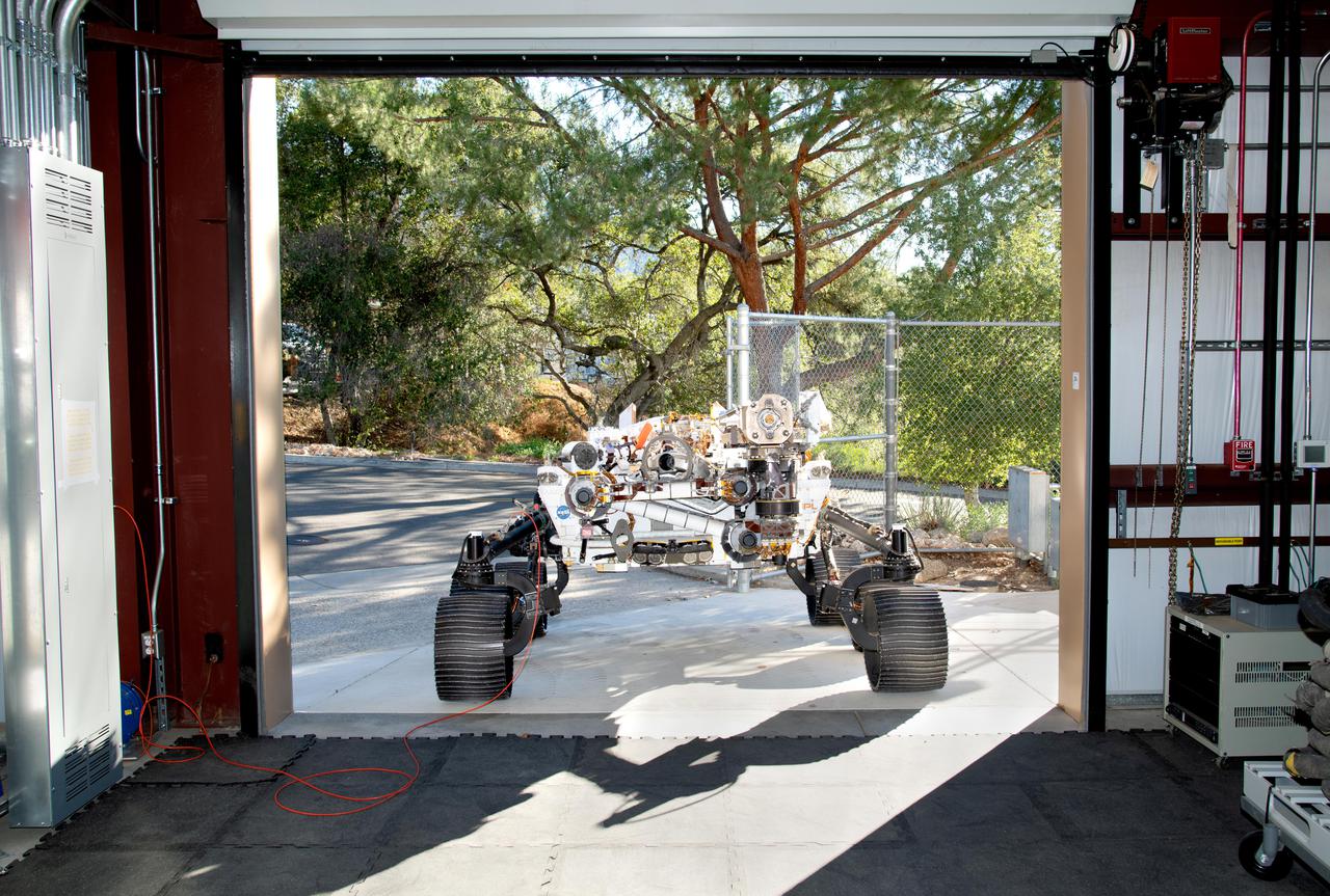
Short for Operational Perseverance Twin for Integration of Mechanisms and Instruments Sent to Mars, OPTIMISM faces a doorway of the Mars Yard garage at NASA's Jet Propulsion Laboratory on Oct. 29, 2021. Referred to generically as a vehicle system test bed, OPTIMISM was recently updated with additional mobility software and the bulk of the complex sample caching system. As with vehicle system test beds for other Mars rovers, OPTIMISM is used to test moves and scenarios in the Mars Yard's simulated Red Planet landscape to help ensure that its twin on Mars can safely execute the commands sent by Earth-bound controllers. The tests could also potentially reveal unexpected problems Perseverance might encounter. With longer drives in Perseverance's near future, another job for OPTIMISM will involve presenting new challenges to the rover's autonomous navigation system, or AutoNav. A key objective for Perseverance's mission on Mars is astrobiology, including the search for signs of ancient microbial life. The rover will characterize the planet's geology and past climate, pave the way for human exploration of the Red Planet, and be the first mission to collect and cache Martian rock and regolith (broken rock and dust). Subsequent NASA missions, in cooperation with ESA (European Space Agency), would send spacecraft to Mars to collect these sealed samples from the surface and return them to Earth for in-depth analysis. The Mars 2020 Perseverance mission is part of NASA's Moon to Mars exploration approach, which includes Artemis missions to the Moon that will help prepare for human exploration of the Red Planet. https://photojournal.jpl.nasa.gov/catalog/PIA24527
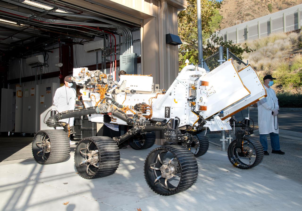
Updated with new features, including additional mobility software and the bulk of the sample caching system, the Earthly twin of NASA's Perseverance Mars rover arrives at the Mars Yard garage at the agency's Jet Propulsion Laboratory on Oct. 29, 2021. The vehicle is generically referred to as a vehicle system test bed but goes by the name OPTIMISM (short for Operational Perseverance Twin for Integration of Mechanisms and Instruments Sent to Mars). As with vehicle system test beds for other Mars rovers, OPTIMISM is used to test moves and scenarios in the Mars Yard's simulated Red Planet landscape to help ensure that its twin on Mars can safely execute the commands sent by Earth-bound controllers. The tests could also potentially reveal unexpected problems Perseverance might encounter. With longer drives in Perseverance's near future, another job for OPTIMISM will involve presenting new challenges to the rover's autonomous navigation system, or AutoNav. A key objective for Perseverance's mission on Mars is astrobiology, including the search for signs of ancient microbial life. The rover will characterize the planet's geology and past climate, pave the way for human exploration of the Red Planet, and be the first mission to collect and cache Martian rock and regolith (broken rock and dust). Subsequent NASA missions, in cooperation with ESA (European Space Agency), would send spacecraft to Mars to collect these sealed samples from the surface and return them to Earth for in-depth analysis. The Mars 2020 Perseverance mission is part of NASA's Moon to Mars exploration approach, which includes Artemis missions to the Moon that will help prepare for human exploration of the Red Planet. https://photojournal.jpl.nasa.gov/catalog/PIA24528

This photograph shows a modified General Dynamics AFTI/F-111A Aardvark with supercritical mission adaptive wings (MAW) installed. The four dark bands on the right wing are the locations of pressure orifices used to measure surface pressures and shock locations on the MAW. The El Paso Mountains and Red Rock Canyon State Park Califonia, about 30 miles northwest of Edwards Air Force Base, are seen directly in the background. With the phasing out of the TACT program came a renewed effort by the Air Force Flight Dynamics Laboratory to extend supercritical wing technology to a higher level of performance. In the early 1980s the supercritical wing on the F-111A aircraft was replaced with a wing built by Boeing Aircraft Company System called a “mission adaptive wing” (MAW), and a joint NASA and Air Force program called Advanced Fighter Technology Integration (AFTI) was born.
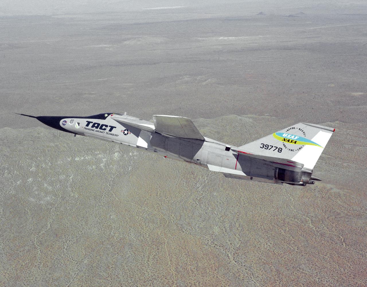
The General Dynamics TACT/F-111A Aardvark is seen In a banking-turn over the California Mojave desert. This photograph affords a good view of the supercritical wing airfoil shape. Starting in 1971 the NASA Flight Research Center and the Air Force undertook a major research and flight testing program, using F-111A (#63-9778), which would span almost 20 years before completion. Intense interest over the results coming from the NASA F-8 supercritical wing program spurred NASA and the Air Force to modify the General Dynamics F-111A to explore the application of supercritical wing technology to maneuverable military aircraft. This flight program was called Transonic Aircraft Technology (TACT).
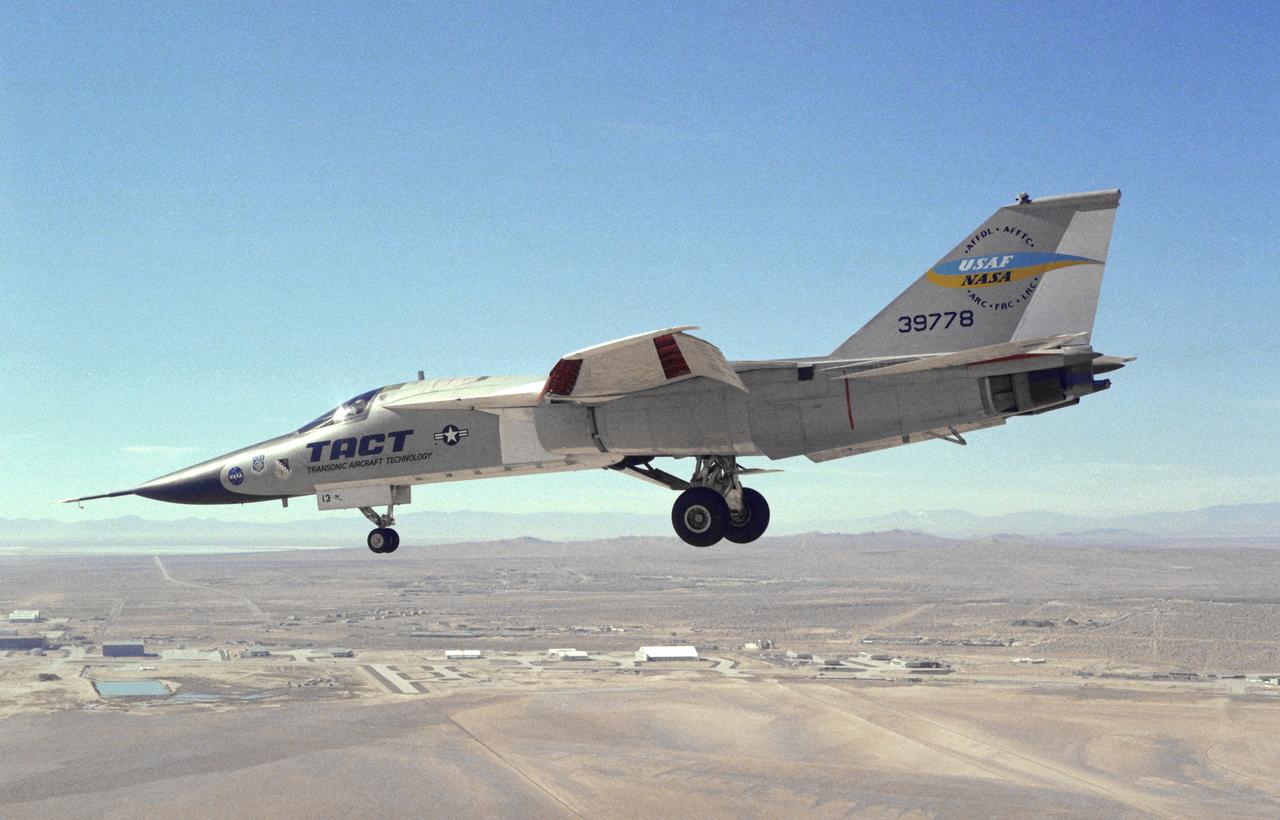
This photograph shows a modified General Dynamics TACT/F-111A Aardvaark with supercritical wings installed. The aircraft, with flaps and landing gear down, is in a decending turn over Rogers Dry Lakebed at Edwards Air Force Base. Starting in 1971 the NASA Flight Research Center and the Air Force undertook a major research and flight testing program, using F-111A (#63-9778), which would span almost 20 years before completion. Intense interest over the results coming from the NASA F-8 supercritical wing program spurred NASA and the Air Force to modify the General Dynamics-Convair F-111A to explore the application of supercritical wing technology to maneuverable military aircraft. This flight program was called Transonic Aircraft Technology (TACT).
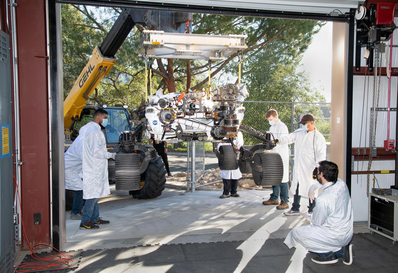
On Oct. 29, 2021, a heavy-duty vehicle transports the Perseverance rover's engineering model from a test lab to the Mars Yard garage at NASA's Jet Propulsion Laboratory. Short for Operational Perseverance Twin for Integration of Mechanisms and Instruments Sent to Mars, OPTIMISM is generically referred to as a vehicle system test bed. As with vehicle system test beds for other Mars rovers, OPTIMISM is used to test moves and scenarios in the Mars Yard's simulated Red Planet landscape to help ensure that its twin on Mars can safely execute the commands sent by Earth-bound controllers. The tests could also potentially reveal unexpected problems Perseverance might encounter. With longer drives in Perseverance's near future, another job for OPTIMISM will involve presenting new challenges to the rover's autonomous navigation system, or AutoNav. A key objective for Perseverance's mission on Mars is astrobiology, including the search for signs of ancient microbial life. The rover will characterize the planet's geology and past climate, pave the way for human exploration of the Red Planet, and be the first mission to collect and cache Martian rock and regolith (broken rock and dust). Subsequent NASA missions, in cooperation with ESA (European Space Agency), would send spacecraft to Mars to collect these sealed samples from the surface and return them to Earth for in-depth analysis. The Mars 2020 Perseverance mission is part of NASA's Moon to Mars exploration approach, which includes Artemis missions to the Moon that will help prepare for human exploration of the Red Planet. https://photojournal.jpl.nasa.gov/catalog/PIA24526
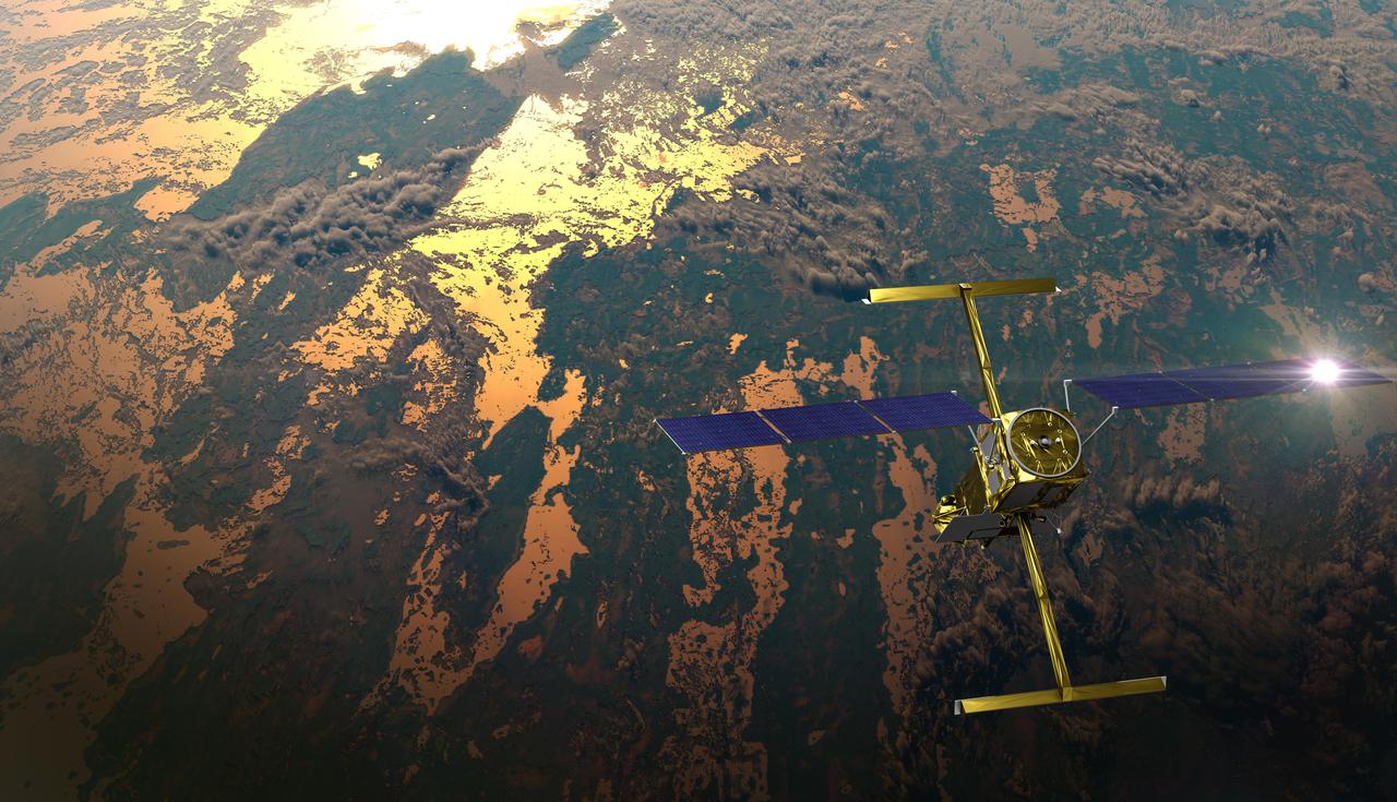
The international Surface Water and Ocean Topography (SWOT) satellite is shown in orbit over Earth in this illustration, with sunlight glinting off one of its solar arrays and both antennas of its Ka-band Radar Interferometer (KaRIn) instrument extended. The mission is a collaborative effort between NASA and the French space agency Centre National d'Études Spatiales (CNES) – with contributions from the Canadian Space Agency (CSA) and the UK Space Agency. KaRIn is the scientific heart of the SWOT satellite, which will survey the water on more than 90% of Earth's surface, measuring the height of water in lakes, rivers, reservoirs, and the ocean. To do that, KaRIn will transmit radar pulses to Earth's surface and use its two antennas to triangulate the return signals that bounce back. Mounted at the ends of a boom 33 feet (10 meters) long, the antennas will collect data along a swath 30 miles (50 kilometers) wide on either side of the satellite. KaRIn will operate in two modes: A lower-resolution mode over the ocean will involve significant onboard processing of the data to reduce the volume of information sent during downlinks to Earth; a higher-resolution mode will be used mainly over land. Scheduled to launch from Vandenberg Space Force Base in Central California on Dec. 15, 2022, SWOT is being jointly developed by NASA and CNES, with contributions from the CSA and the UK Space Agency. NASA's Jet Propulsion Laboratory, which is managed for the agency by Caltech in Pasadena, California, leads the U.S. component of the project. For the flight system payload, NASA is providing the Ka-band Radar Interferometer (KaRIn) instrument, a GPS science receiver, a laser retroreflector, a two-beam microwave radiometer, and NASA instrument operations. CNES is providing the Doppler Orbitography and Radioposition Integrated by Satellite (DORIS) system, the dual frequency Poseidon altimeter (developed by Thales Alenia Space), the KaRIn radio-frequency subsystem (together with Thales Alenia Space and with support from the UK Space Agency), the satellite platform, and ground control segment. CSA is providing the KaRIn high-power transmitter assembly. NASA is providing the launch vehicle and associated launch services. https://photojournal.jpl.nasa.gov/catalog/PIA25595
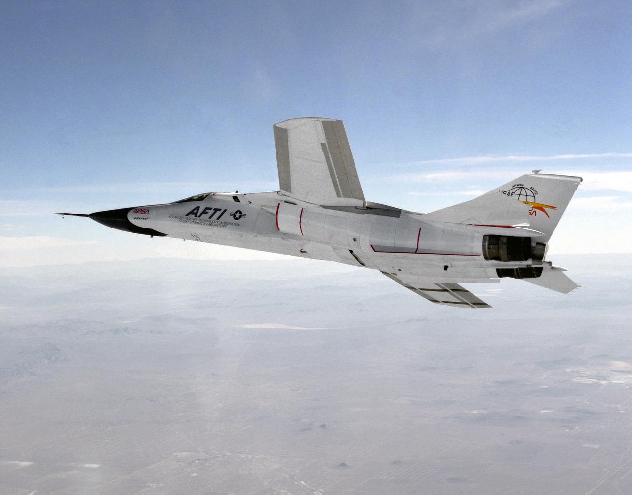
This photograph shows a modified General Dynamics AFTI/F-111A Aardvark with supercritical mission adaptive wings (MAW) installed. The AFTI/F111A is seen banking towards Rodgers Dry Lake and Edwards Air Force Base. With the phasing out of the TACT program came a renewed effort by the Air Force Flight Dynamics Laboratory to extend supercritical wing technology to a higher level of performance. In the early 1980s the supercritical wing on the F-111A aircraft was replaced with a wing built by Boeing Aircraft Company System called a “mission adaptive wing” (MAW), and a joint NASA and Air Force program called Advanced Fighter Technology Integration (AFTI) was born.