
Archival pictures of the Integrated Structural Assembly of Advanced Composites (ISAAC) In Clean Room in Building 1232A. Integrated Structural Assembly of Advanced Composites (ISAAC) is a state of the art composite manufacturing robot. ISAAC was purchased from Electroimpact and installed in 2015. NASA Langley was the first NASA Center to receive this technology and the third manufacturing facility in the world to receive an ISAAC. The robot has 8 degrees of freedom and an accuracy rate of +/- .05". ISAAC also has several detachable end effectors, making it a versatile machine. Similar robots have become very popular in the automotive and commercial flight industries. At NASA Langley Research Center, ISAAC supports research on the design and manufacturing of composite parts.
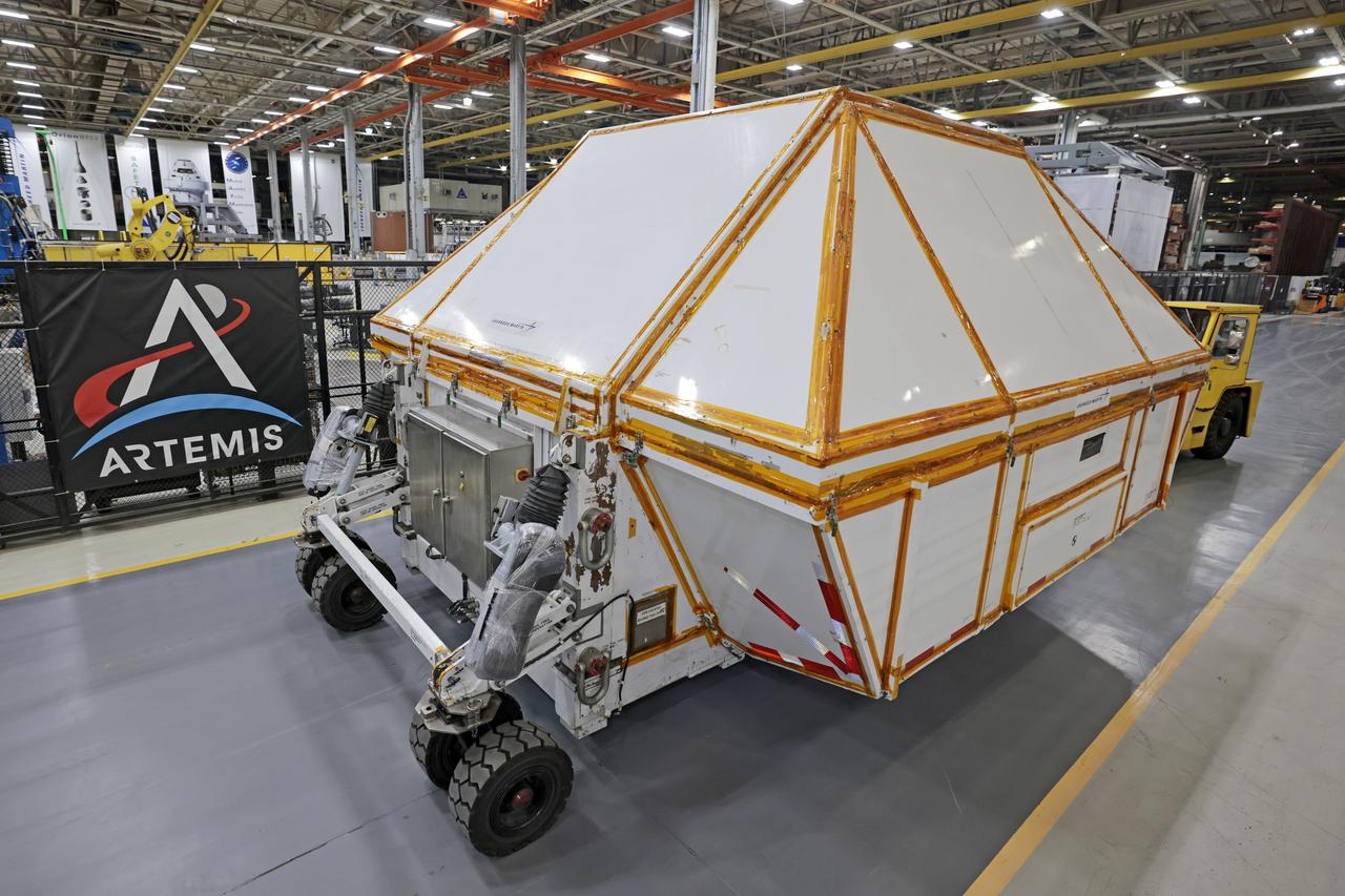
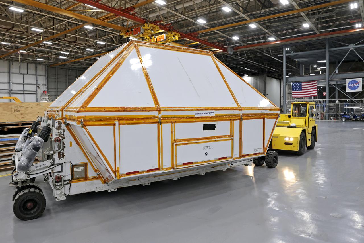
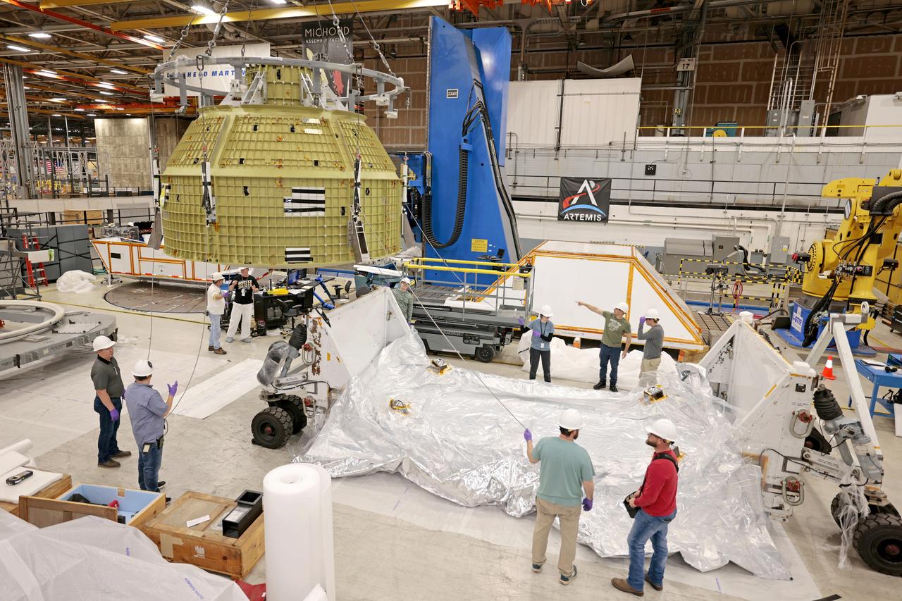
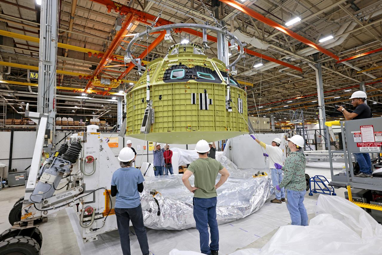
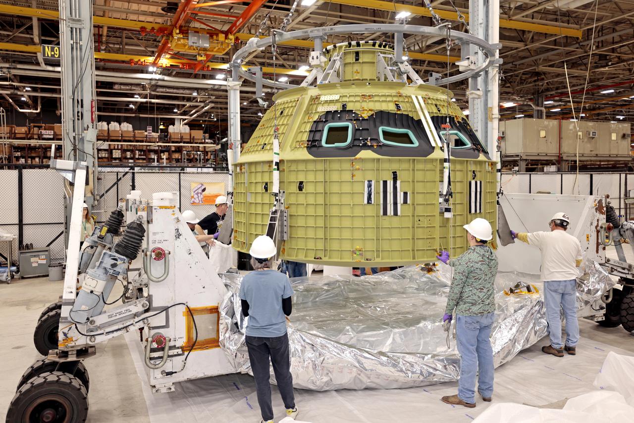
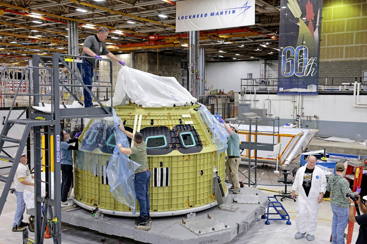
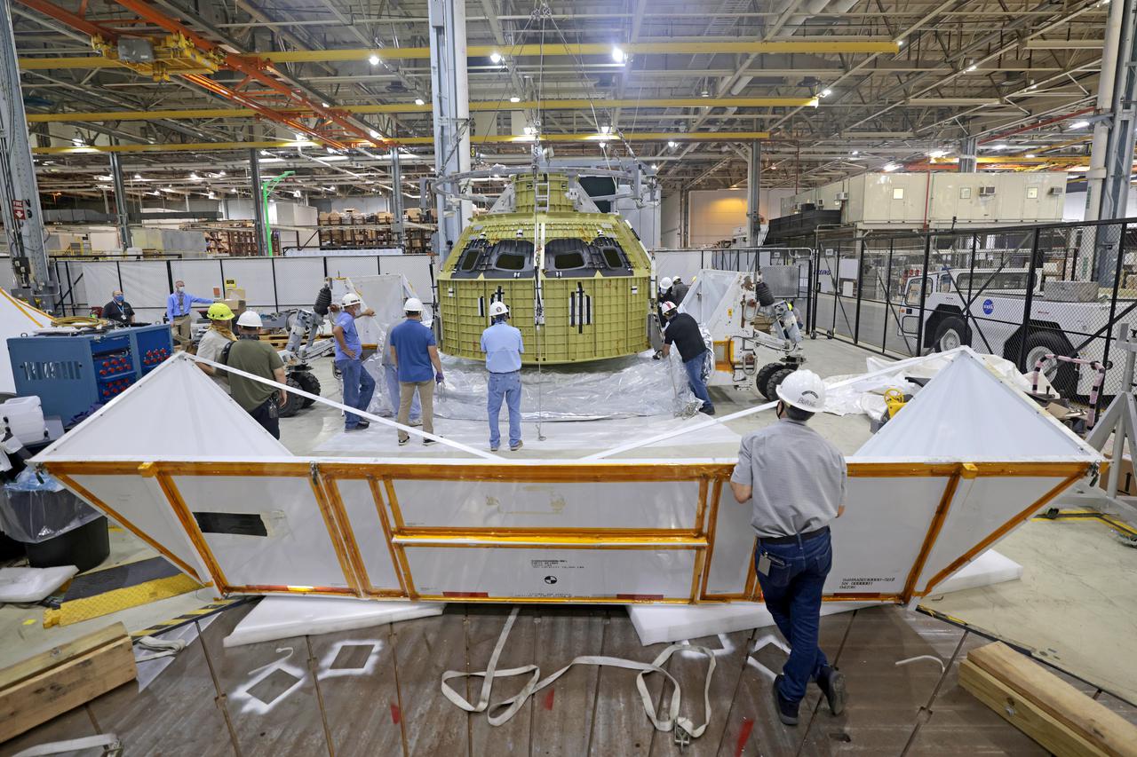
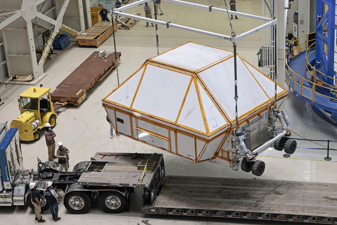
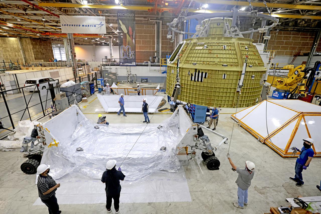
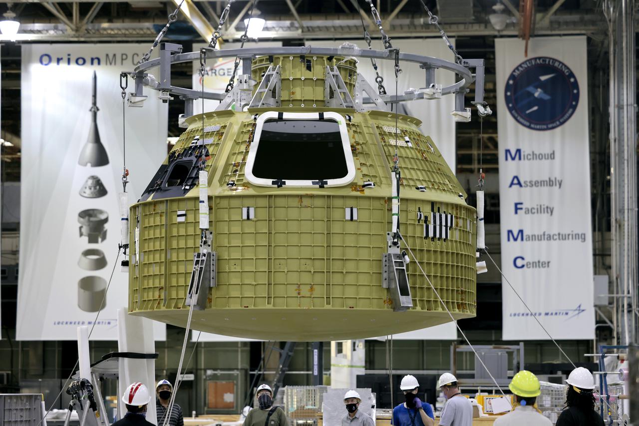
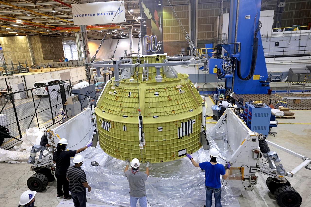
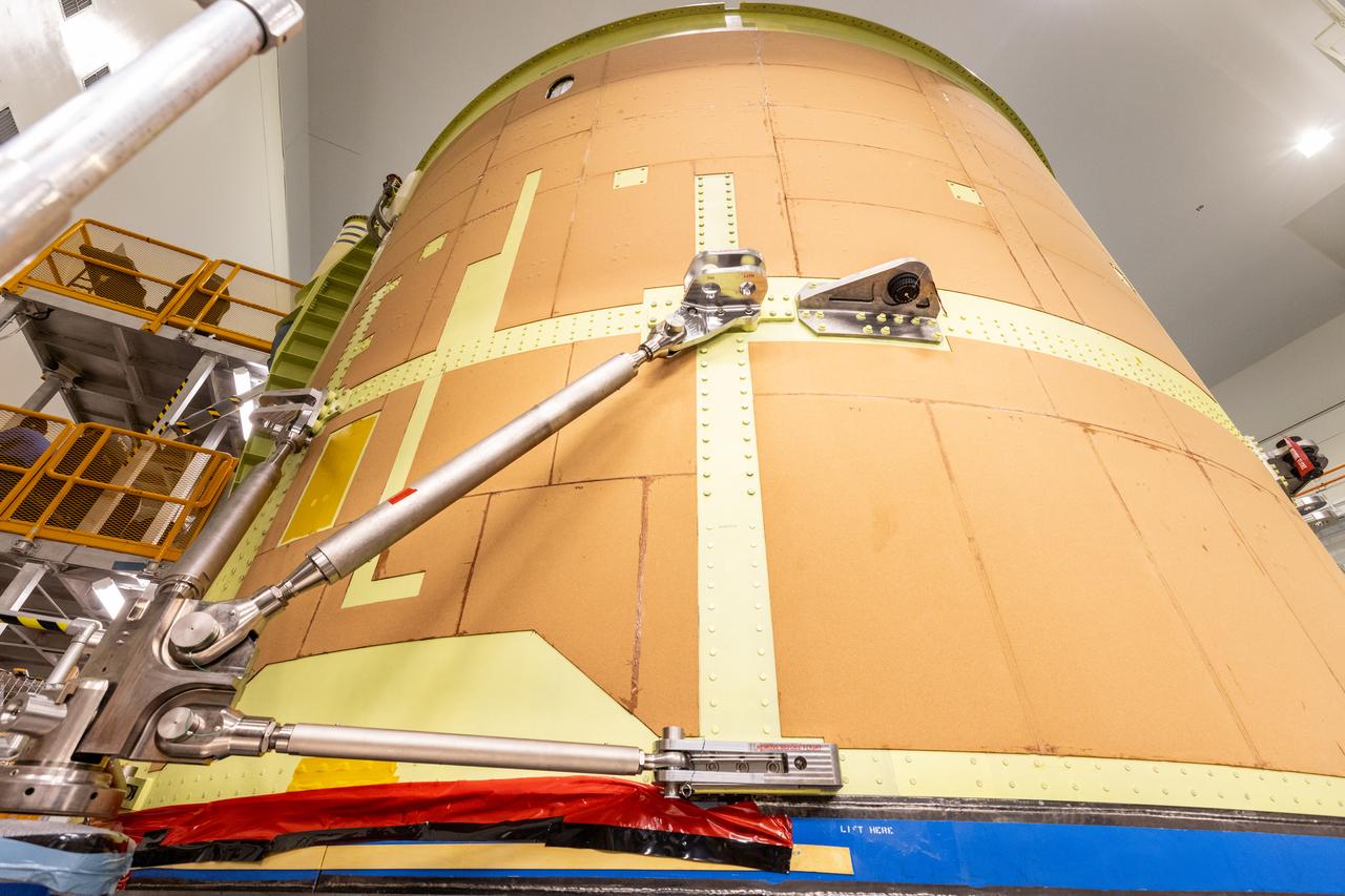
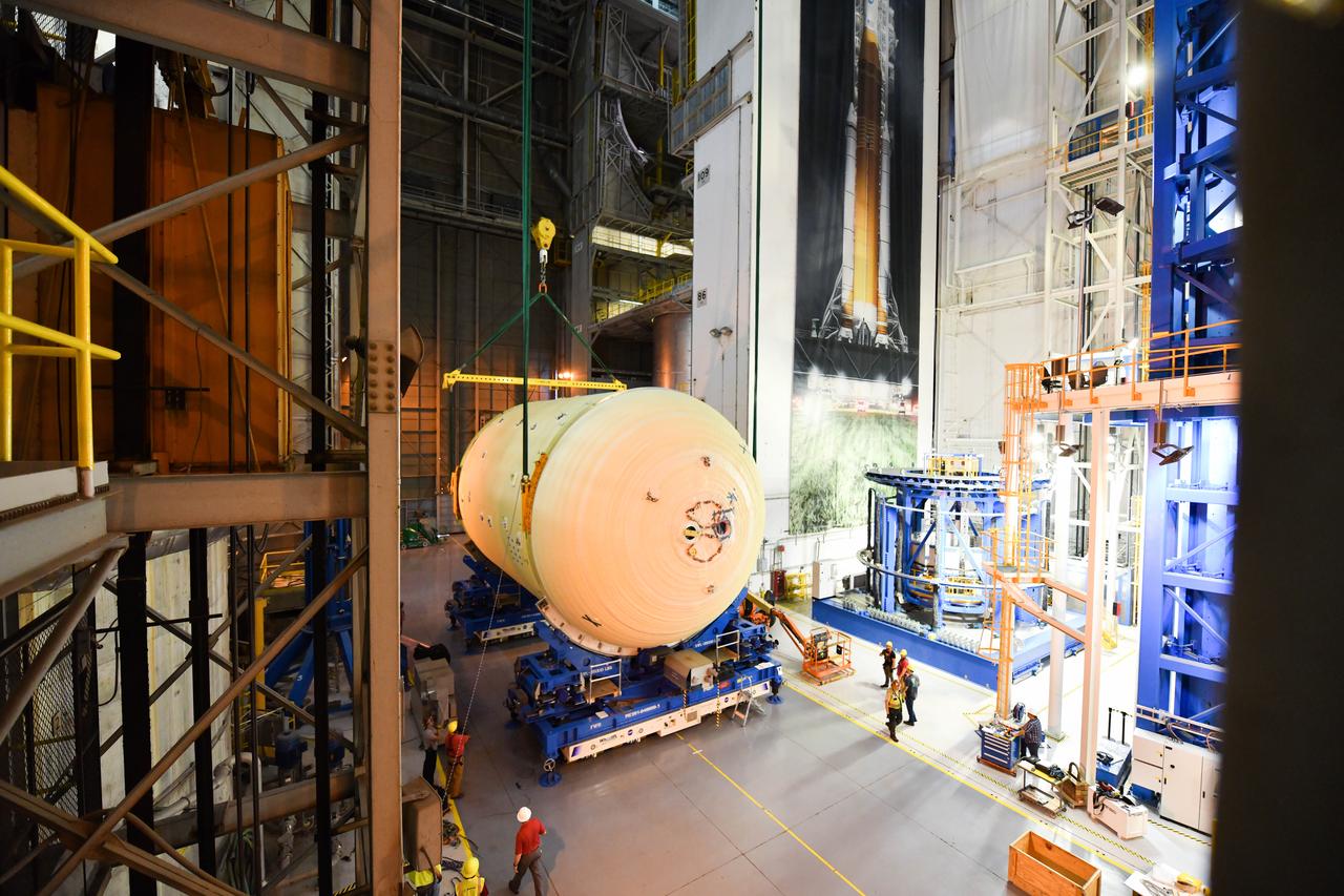
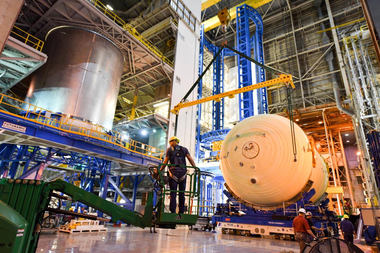
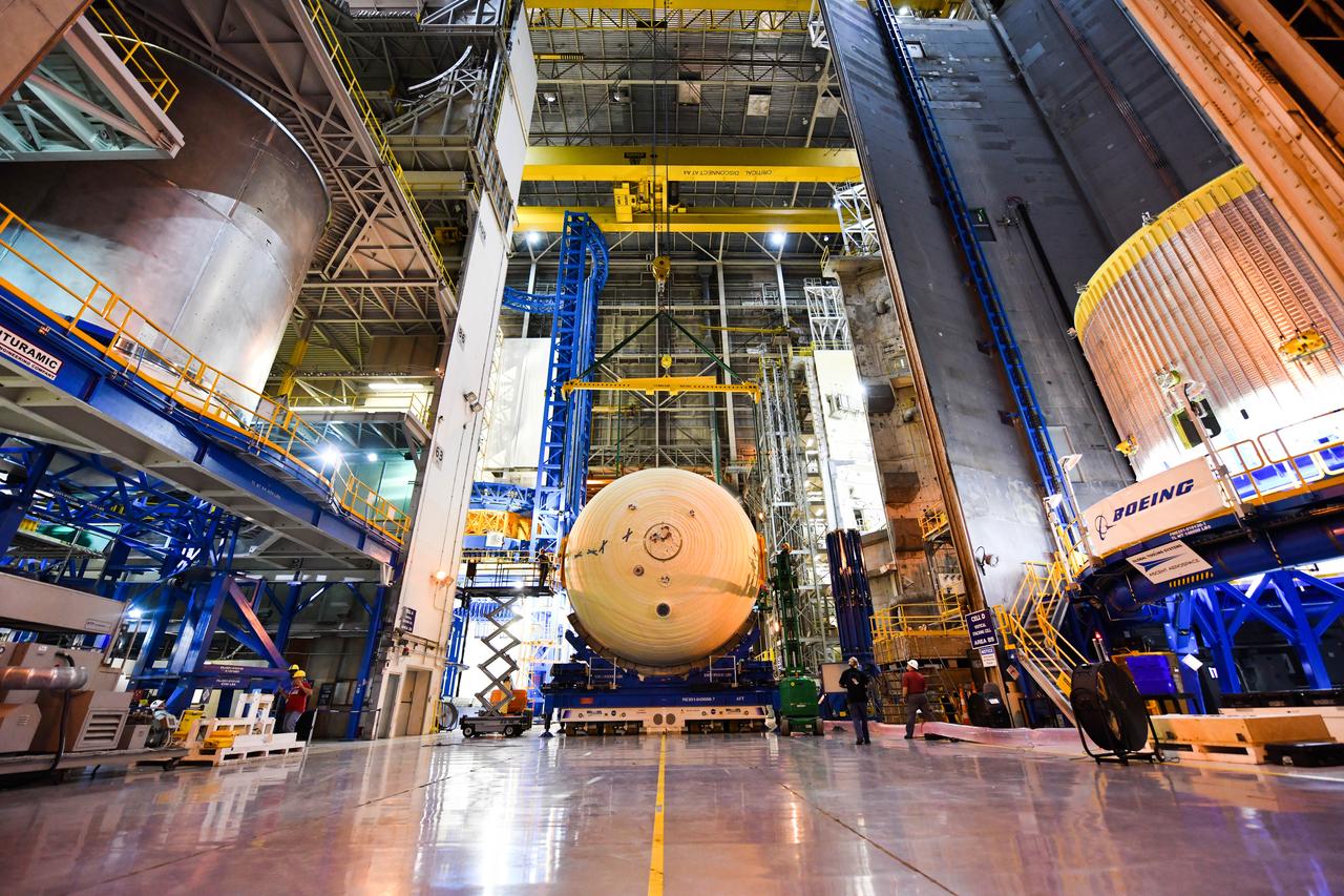
Teams at NASA’s Michoud Assembly Facility in New Orleans prepare the completed Orion pressure vessel for the Artemis IV mission for shipment to NASA’s Kennedy Space Center in Florida. The pressure vessel, which was assembled by lead contractor, Lockheed Martin, is the Orion crew module primary structure – the core upon which all other elements of Orion’s crew module are integrated. The structure is critical to Artemis crews as it holds the pressurized atmosphere astronauts breathe and work in a while in the vacuum of deep space. Once the module arrives at Kennedy’s Vehicle Assembly Building high bay, teams will begin integration of the pressure vessel with the Orion spacecraft crew module adapter and other assembly. With Artemis missions, NASA will land the first woman and the first person of color on the lunar surface, paving the way for human exploration of the Moon and on to Mars. Image credit: NASA/Michael DeMocker
Teams at NASA’s Michoud Assembly Facility in New Orleans prepare the completed Orion pressure vessel for the Artemis IV mission for shipment to NASA’s Kennedy Space Center in Florida. The pressure vessel, which was assembled by lead contractor, Lockheed Martin, is the Orion crew module primary structure – the core upon which all other elements of Orion’s crew module are integrated. The structure is critical to Artemis crews as it holds the pressurized atmosphere astronauts breathe and work in a while in the vacuum of deep space. Once the module arrives at Kennedy’s Vehicle Assembly Building high bay, teams will begin integration of the pressure vessel with the Orion spacecraft crew module adapter and other assembly. With Artemis missions, NASA will land the first woman and the first person of color on the lunar surface, paving the way for human exploration of the Moon and on to Mars. Image credit: NASA/Michael DeMocker
Teams at NASA’s Michoud Assembly Facility in New Orleans prepare the completed Orion pressure vessel for the Artemis IV mission for shipment to NASA’s Kennedy Space Center in Florida. The pressure vessel, which was assembled by lead contractor, Lockheed Martin, is the Orion crew module primary structure – the core upon which all other elements of Orion’s crew module are integrated. The structure is critical to Artemis crews as it holds the pressurized atmosphere astronauts breathe and work in a while in the vacuum of deep space. Once the module arrives at Kennedy’s Vehicle Assembly Building high bay, teams will begin integration of the pressure vessel with the Orion spacecraft crew module adapter and other assembly. With Artemis missions, NASA will land the first woman and the first person of color on the lunar surface, paving the way for human exploration of the Moon and on to Mars. Image credit: NASA/Michael DeMocker
Teams at NASA’s Michoud Assembly Facility in New Orleans prepare the completed Orion pressure vessel for the Artemis IV mission for shipment to NASA’s Kennedy Space Center in Florida. The pressure vessel, which was assembled by lead contractor, Lockheed Martin, is the Orion crew module primary structure – the core upon which all other elements of Orion’s crew module are integrated. The structure is critical to Artemis crews as it holds the pressurized atmosphere astronauts breathe and work in a while in the vacuum of deep space. Once the module arrives at Kennedy’s Vehicle Assembly Building high bay, teams will begin integration of the pressure vessel with the Orion spacecraft crew module adapter and other assembly. With Artemis missions, NASA will land the first woman and the first person of color on the lunar surface, paving the way for human exploration of the Moon and on to Mars. Image credit: NASA/Michael DeMocker
Teams at NASA’s Michoud Assembly Facility in New Orleans prepare the completed Orion pressure vessel for the Artemis IV mission for shipment to NASA’s Kennedy Space Center in Florida. The pressure vessel, which was assembled by lead contractor, Lockheed Martin, is the Orion crew module primary structure – the core upon which all other elements of Orion’s crew module are integrated. The structure is critical to Artemis crews as it holds the pressurized atmosphere astronauts breathe and work in a while in the vacuum of deep space. Once the module arrives at Kennedy’s Vehicle Assembly Building high bay, teams will begin integration of the pressure vessel with the Orion spacecraft crew module adapter and other assembly. With Artemis missions, NASA will land the first woman and the first person of color on the lunar surface, paving the way for human exploration of the Moon and on to Mars. Image credit: NASA/Michael DeMocker
Teams at NASA’s Michoud Assembly Facility in New Orleans prepare the completed Orion pressure vessel for the Artemis IV mission for shipment to NASA’s Kennedy Space Center in Florida. The pressure vessel, which was assembled by lead contractor, Lockheed Martin, is the Orion crew module primary structure – the core upon which all other elements of Orion’s crew module are integrated. The structure is critical to Artemis crews as it holds the pressurized atmosphere astronauts breathe and work in a while in the vacuum of deep space. Once the module arrives at Kennedy’s Vehicle Assembly Building high bay, teams will begin integration of the pressure vessel with the Orion spacecraft crew module adapter and other assembly. With Artemis missions, NASA will land the first woman and the first person of color on the lunar surface, paving the way for human exploration of the Moon and on to Mars. Image credit: NASA/Michael DeMocker

Teams at NASA’s Michoud Assembly Facility in New Orleans prepare the completed Orion pressure vessel for the Artemis IV mission for shipment to NASA’s Kennedy Space Center in Florida. The pressure vessel, which was assembled by lead contractor, Lockheed Martin, is the Orion crew module primary structure – the core upon which all other elements of Orion’s crew module are integrated. The structure is critical to Artemis crews as it holds the pressurized atmosphere astronauts breathe and work in a while in the vacuum of deep space. Once the module arrives at Kennedy’s Vehicle Assembly Building high bay, teams will begin integration of the pressure vessel with the Orion spacecraft crew module adapter and other assembly. With Artemis missions, NASA will land the first woman and the first person of color on the lunar surface, paving the way for human exploration of the Moon and on to Mars. Image credit: NASA/Michael DeMocker
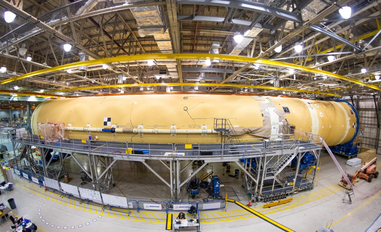
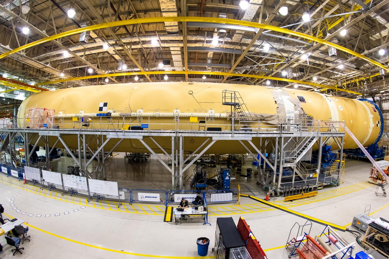
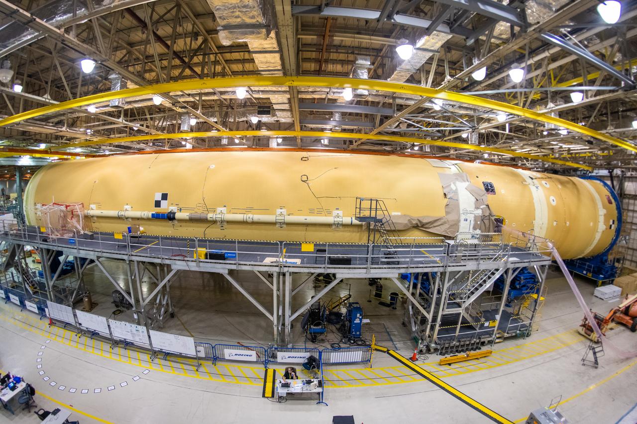
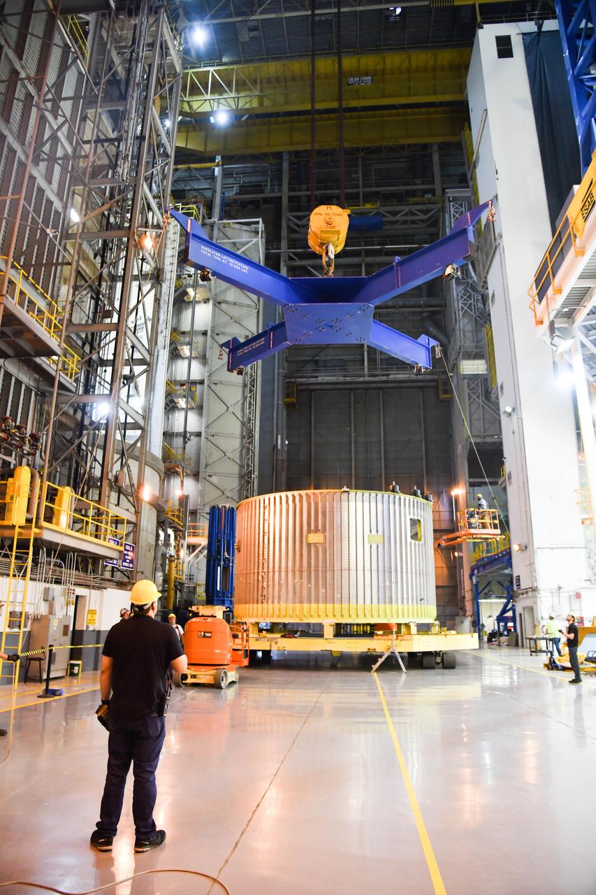
Technicians at NASA’s Michoud Assembly Facility in New Orleans completed the “forward join,” which connects structures to form the top part of NASA’s Space Launch System (SLS) rocket’s core stage. The first core stage will send Exploration Mission-1, the first integrated flight of SLS and NASA’s Orion spacecraft, out beyond the Moon. The forward join mated three structures: the forward skirt, liquid oxygen tank and intertank. This milestone marks the beginning of integration and assembly of the massive, 212-foot-tall SLS core stage, which will include the rocket’s four RS-25 rocket engines, propellant tanks and flight computers. Now, NASA and Boeing, the SLS prime contractor, will continue to integrate various systems inside the forward part of the core stage and prepare for structural joining of the liquid hydrogen tank and engine section to form the bottom of the stage. These two parts of the core stage will then be assembled to form the largest stage NASA has ever built.
Technicians at NASA’s Michoud Assembly Facility in New Orleans completed the “forward join,” which connects structures to form the top part of NASA’s Space Launch System (SLS) rocket’s core stage. The first core stage will send Exploration Mission-1, the first integrated flight of SLS and NASA’s Orion spacecraft, out beyond the Moon. The forward join mated three structures: the forward skirt, liquid oxygen tank and intertank. This milestone marks the beginning of integration and assembly of the massive, 212-foot-tall SLS core stage, which will include the rocket’s four RS-25 rocket engines, propellant tanks and flight computers. Now, NASA and Boeing, the SLS prime contractor, will continue to integrate various systems inside the forward part of the core stage and prepare for structural joining of the liquid hydrogen tank and engine section to form the bottom of the stage. These two parts of the core stage will then be assembled to form the largest stage NASA has ever built.
Technicians at NASA’s Michoud Assembly Facility in New Orleans completed the “forward join,” which connects structures to form the top part of NASA’s Space Launch System (SLS) rocket’s core stage. The first core stage will send Exploration Mission-1, the first integrated flight of SLS and NASA’s Orion spacecraft, out beyond the Moon. The forward join mated three structures: the forward skirt, liquid oxygen tank and intertank. This milestone marks the beginning of integration and assembly of the massive, 212-foot-tall SLS core stage, which will include the rocket’s four RS-25 rocket engines, propellant tanks and flight computers. Now, NASA and Boeing, the SLS prime contractor, will continue to integrate various systems inside the forward part of the core stage and prepare for structural joining of the liquid hydrogen tank and engine section to form the bottom of the stage. These two parts of the core stage will then be assembled to form the largest stage NASA has ever built.
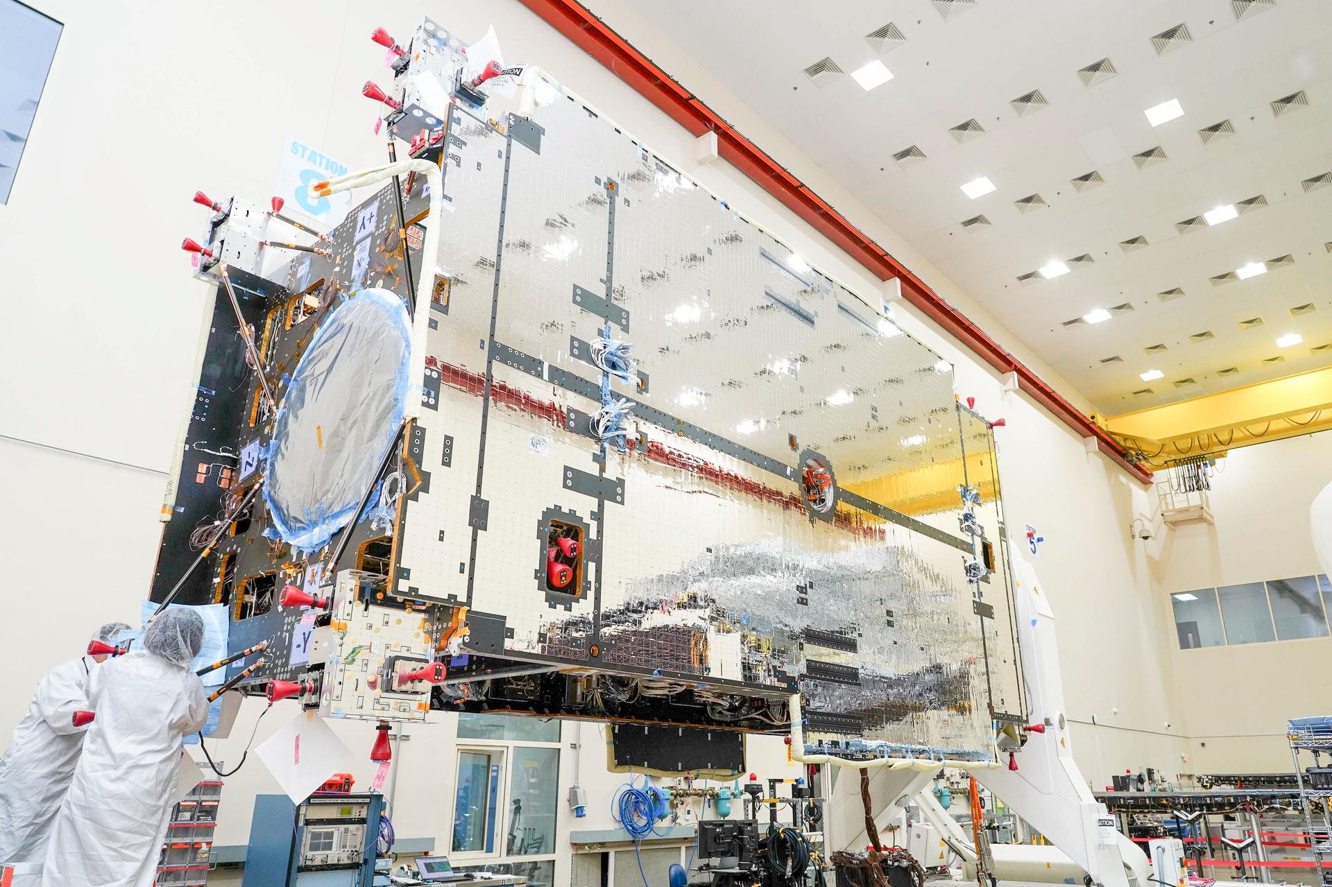
The primary structure of Gateway’s Power and Propulsion Element (PPE) undergoing assembly, integration, and testing at Lanteris Space Systems in Palo Alto, California, on September 29, 2025. Credit: Lanteris Space Systems
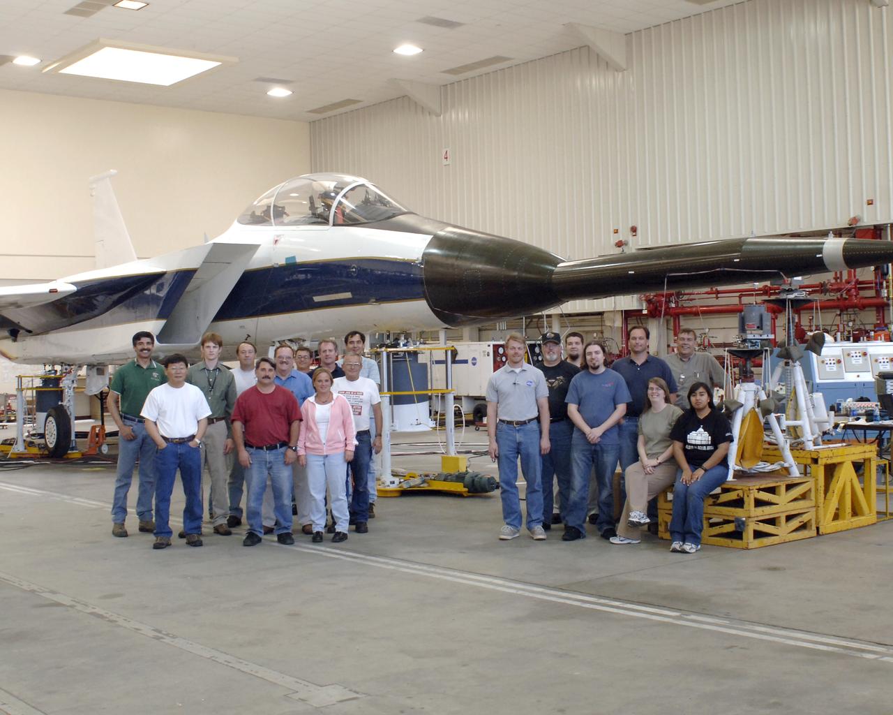
Some of the test team for the Gulfstream Quiet Spike project assembled for a group photo on May 3, 2006. The project seeks to verify the structural integrity of the multi-segmented, articulating spike attachment designed to reduce and control a sonic boom.
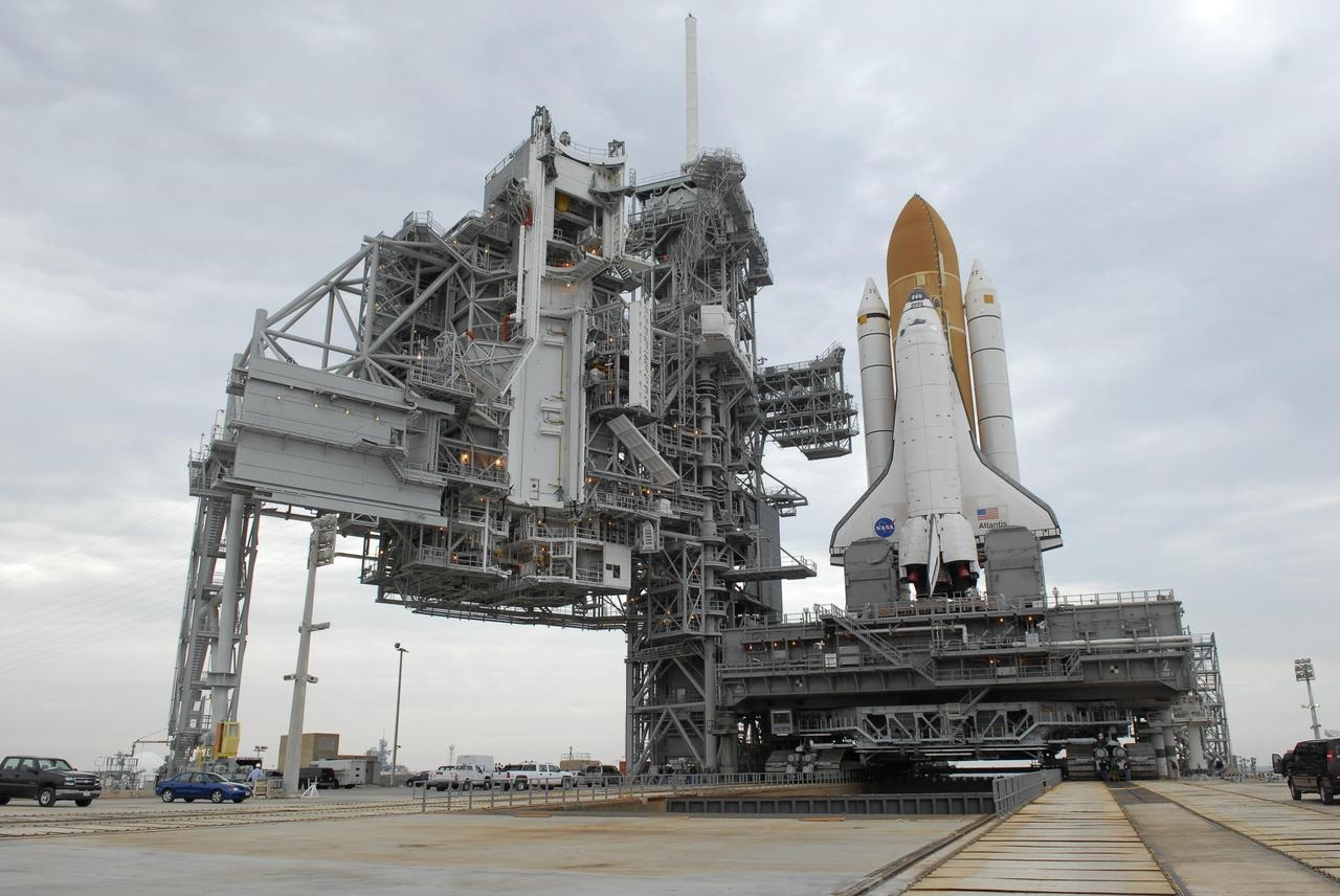
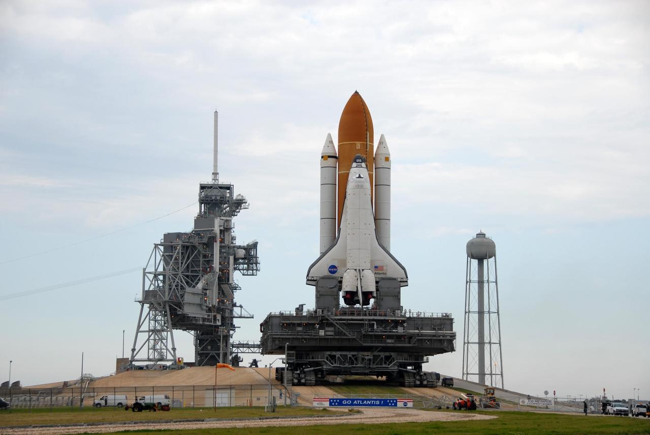
KENNEDY SPACE CENTER, FLA. -- Space Shuttle Atlantis arrives on the hardstand on Launch Pad 39A after a six-hour trek, via the crawler-transporter, from the Vehicle Assembly Building. The first motion out of the assembly building was at 8:19 a.m. At left is the open rotating service structure that will be rolled to enclose the shuttle for protection. Next to the shuttle is the fixed service structure. The mission payload aboard Space Shuttle Atlantis is the S3/S4 integrated truss structure, along with a third set of solar arrays and batteries. The crew of six astronauts will install the truss to continue assembly of the International Space Station. Launch is targeted for March 15. Photo credit: NASA/Kim Shiflett
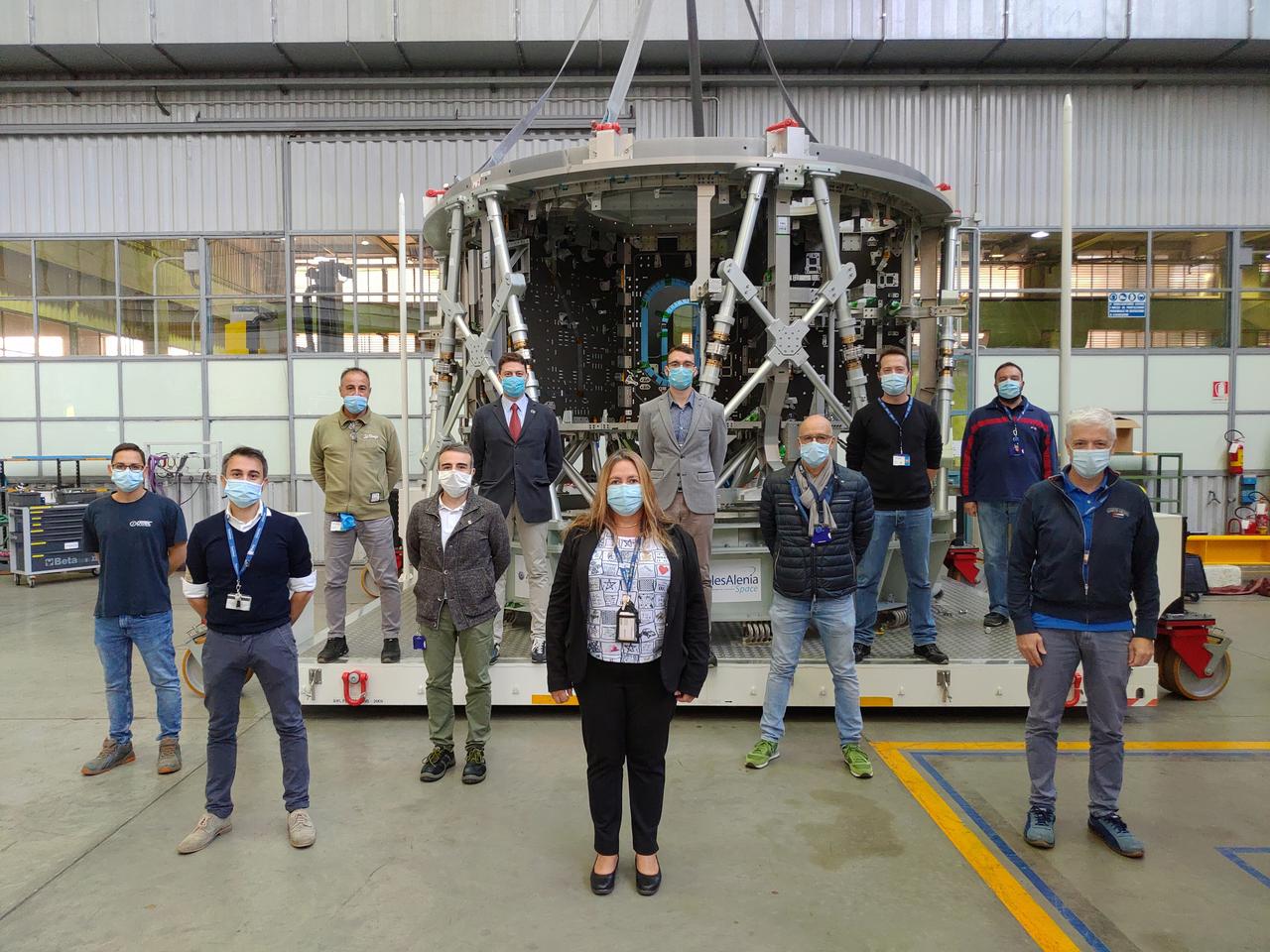
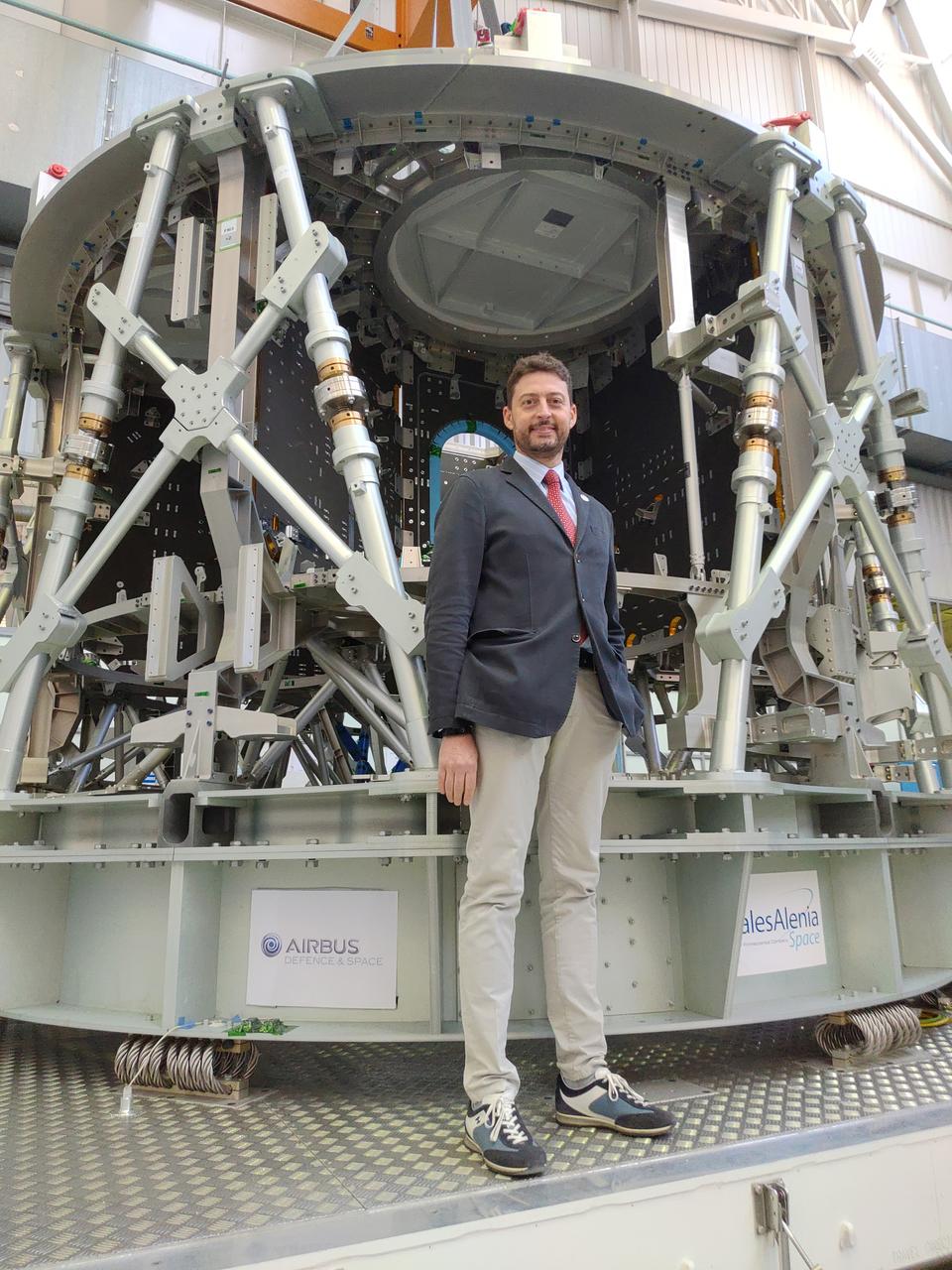
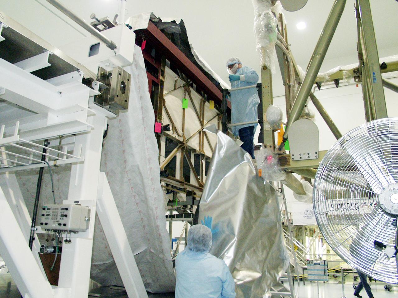
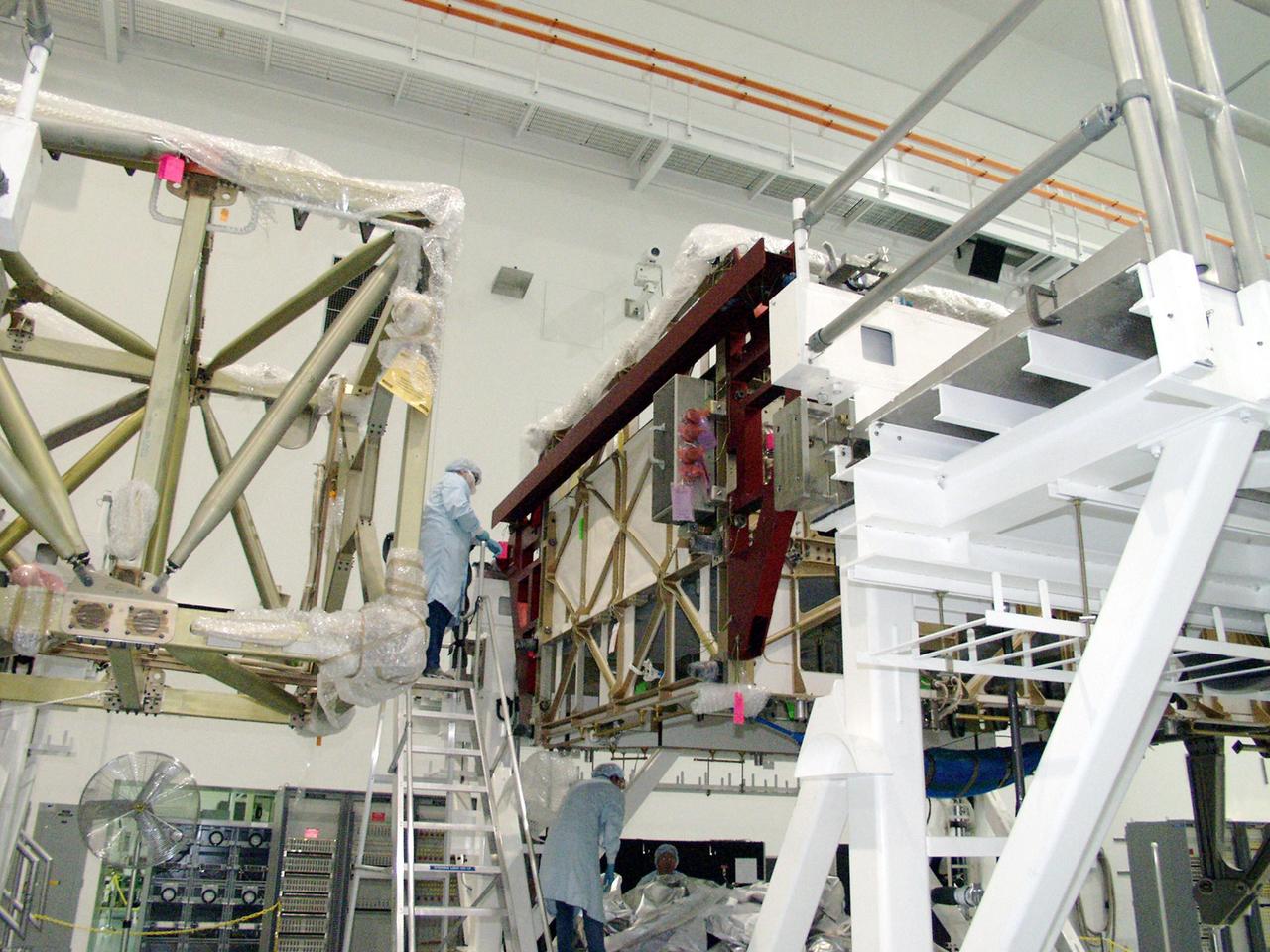
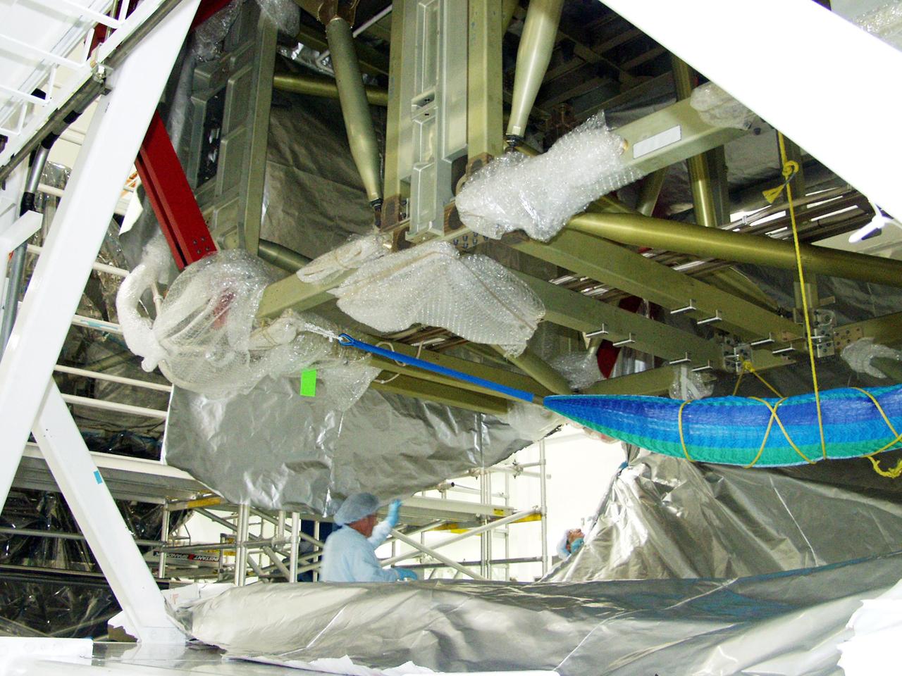
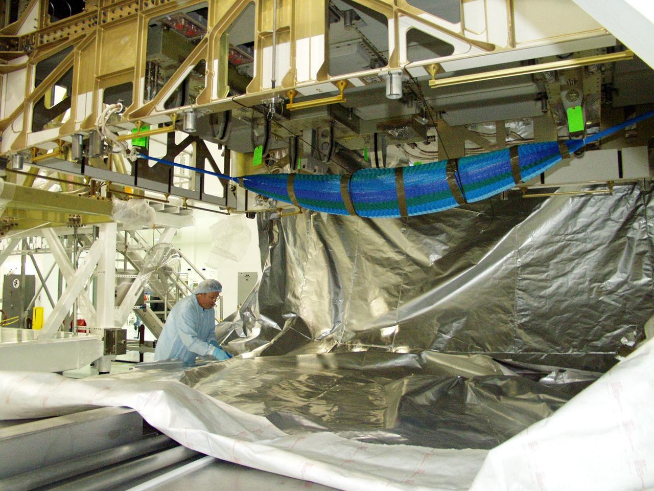
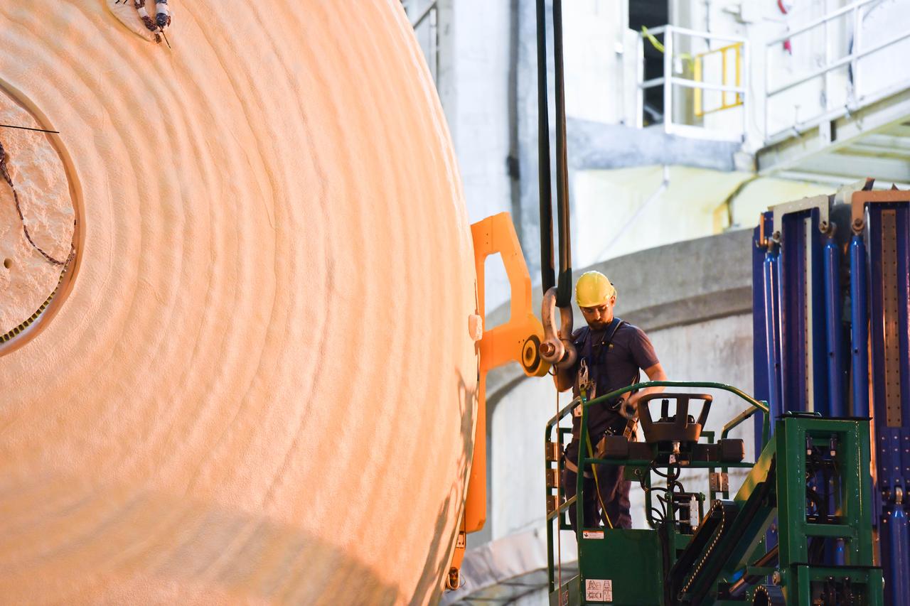
The ESA service module primary structure, which will propel Orion on the Artemis III flight carrying astronauts to land on the surface of the Moon, is ready to ship from Thales Alenia Space in Turin, Italy to Airbus in Bremen, Germany. Giorgio (Gios) Borello, Thales Alenia Space AIT (Assembly, Integration & Testing) mechanical expert, guides the service module structure to the base of the transportation container on Sept. 30, 2020. Airbus will perform final assembly on the service module ahead of shipment to Kennedy Space Center where it will be integrated with the rest of the Orion spacecraft.
The ESA service module primary structure, which will propel Orion on the Artemis III flight carrying astronauts to land on the surface of the Moon, is ready to ship from Thales Alenia Space in Turin, Italy to Airbus in Bremen, Germany. Giorgio (Gios) Borello, Thales Alenia Space AIT (Assembly, Integration & Testing) mechanical expert, guides the service module structure to the base of the transportation container on Sept. 30, 2020. Airbus will perform final assembly on the service module ahead of shipment to Kennedy Space Center where it will be integrated with the rest of the Orion spacecraft.
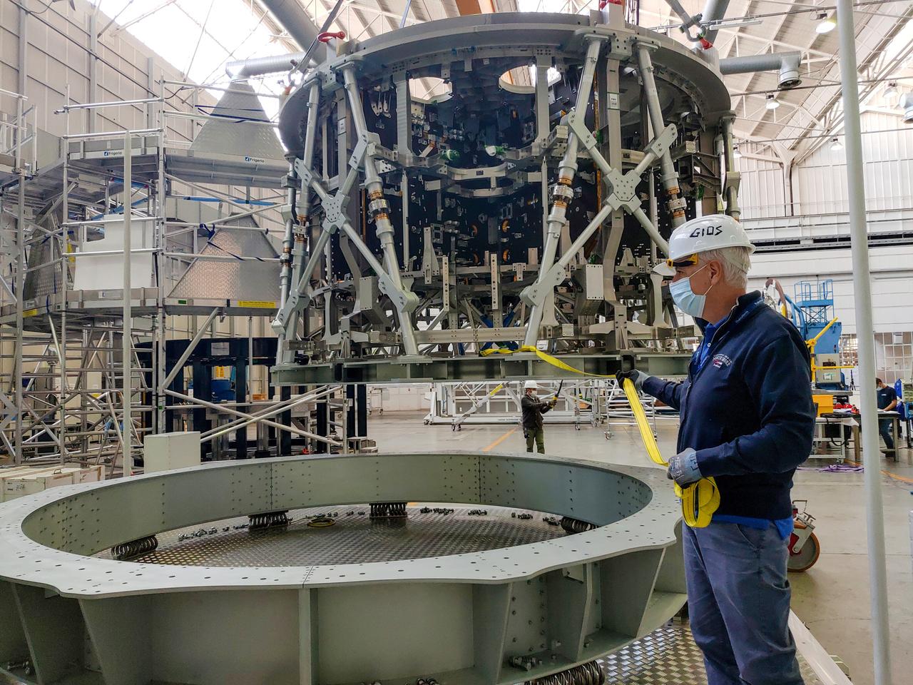
The ESA service module primary structure, which will propel Orion on the Artemis III flight carrying astronauts to land on the surface of the Moon, is ready to ship from Thales Alenia Space in Turin, Italy to Airbus in Bremen, Germany. Giorgio (Gios) Borello, Thales Alenia Space AIT (Assembly, Integration & Testing) mechanical expert, guides the service module structure to the base of the transportation container on Sept. 30, 2020. Airbus will perform final assembly on the service module ahead of shipment to Kennedy Space Center where it will be integrated with the rest of the Orion spacecraft.

Engineers and technicians at NASA’s Michoud Assembly Facility in New Orleans have structurally mated the first of four RS-25 engines to the core stage for NASA’s Space Launch System rocket that will help power the first Artemis mission to the Moon. Integration of the RS-25 engine to the recently completed core stage structure is a collaborative, multistep process for NASA and its partners Boeing, the core stage lead contractor, and Aerojet Rocketdyne, the RS-25 engine lead contractor. To complete the installation, the technicians will now integrate the propulsion and electrical systems. The installation process will be repeated for each of the four RS-25 engines. Offering more payload mass, volume capability and energy to speed missions through space, the SLS rocket, along with NASA’s Gateway in lunar orbit and Orion, is part of NASA’s backbone for deep space exploration and the Artemis lunar program. No other rocket is capable of carrying astronauts in Orion around the Moon in a single mission.

Engineers and technicians at NASA’s Michoud Assembly Facility in New Orleans have structurally mated the first of four RS-25 engines to the core stage for NASA’s Space Launch System rocket that will help power the first Artemis mission to the Moon. Integration of the RS-25 engine to the recently completed core stage structure is a collaborative, multistep process for NASA and its partners Boeing, the core stage lead contractor, and Aerojet Rocketdyne, the RS-25 engine lead contractor. To complete the installation, the technicians will now integrate the propulsion and electrical systems. The installation process will be repeated for each of the four RS-25 engines. Offering more payload mass, volume capability and energy to speed missions through space, the SLS rocket, along with NASA’s Gateway in lunar orbit and Orion, is part of NASA’s backbone for deep space exploration and the Artemis lunar program. No other rocket is capable of carrying astronauts in Orion around the Moon in a single mission.

Engineers and technicians at NASA’s Michoud Assembly Facility in New Orleans have structurally mated the first of four RS-25 engines to the core stage for NASA’s Space Launch System rocket that will help power the first Artemis mission to the Moon. Integration of the RS-25 engine to the recently completed core stage structure is a collaborative, multistep process for NASA and its partners Boeing, the core stage lead contractor, and Aerojet Rocketdyne, the RS-25 engine lead contractor. To complete the installation, the technicians will now integrate the propulsion and electrical systems. The installation process will be repeated for each of the four RS-25 engines. Offering more payload mass, volume capability and energy to speed missions through space, the SLS rocket, along with NASA’s Gateway in lunar orbit and Orion, is part of NASA’s backbone for deep space exploration and the Artemis lunar program. No other rocket is capable of carrying astronauts in Orion around the Moon in a single mission.
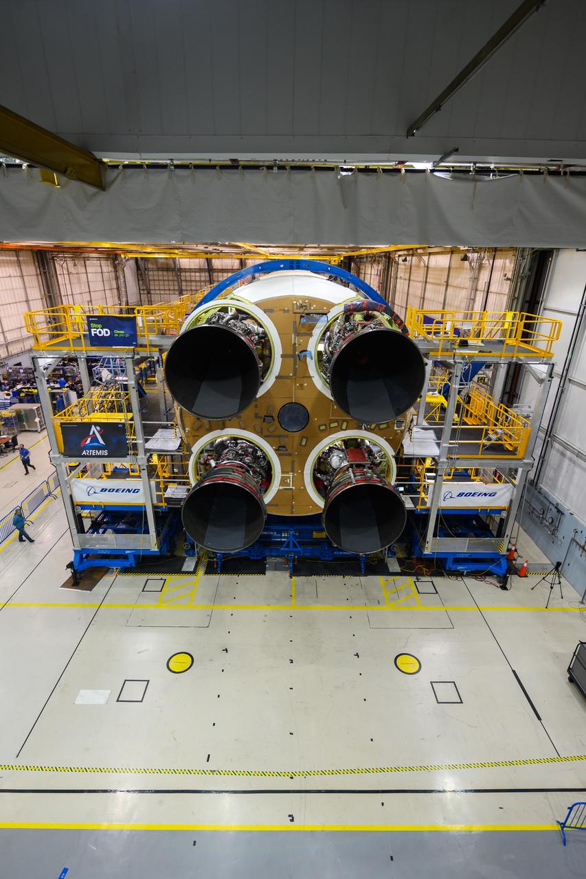
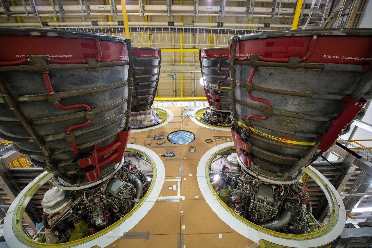
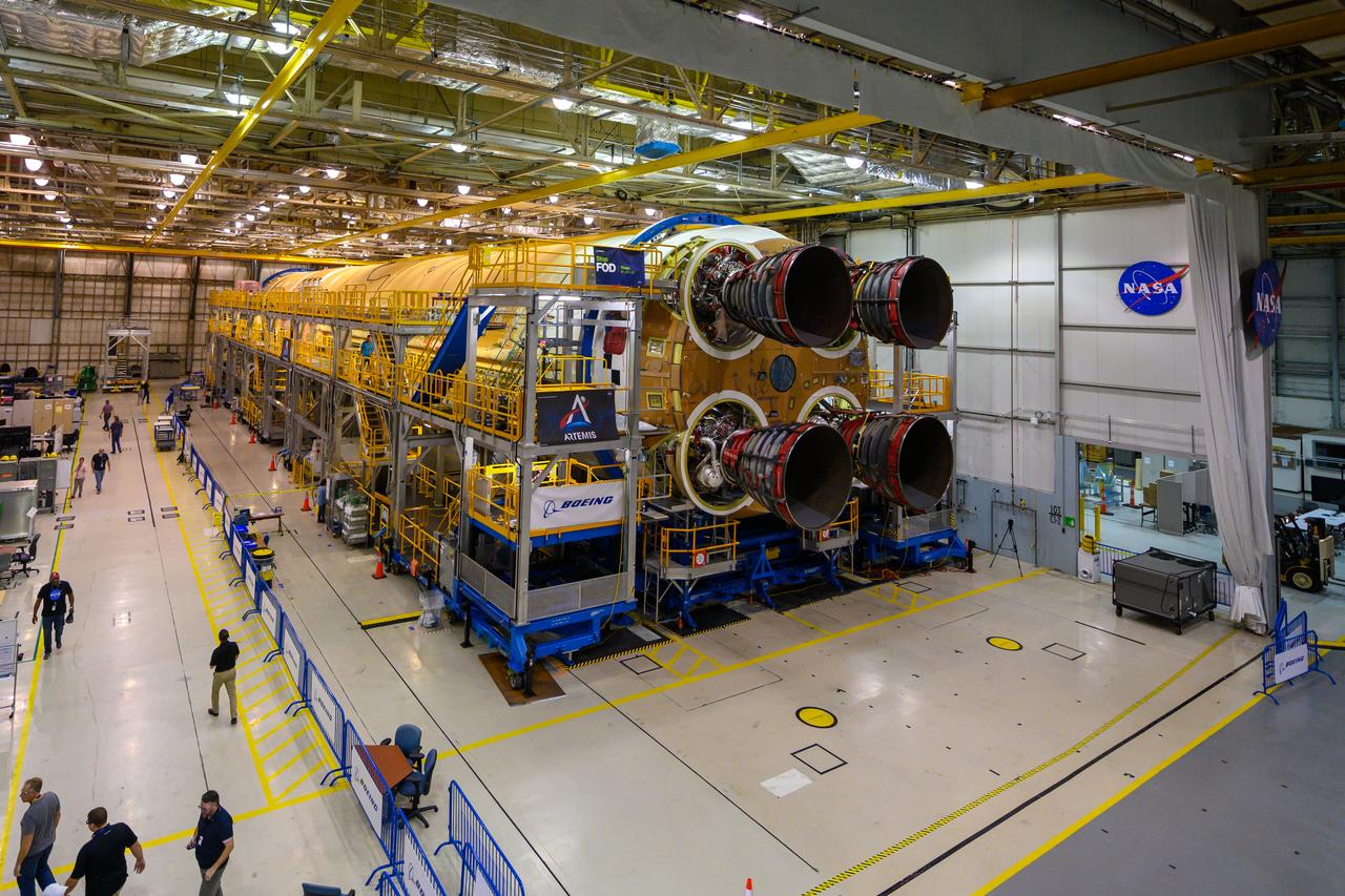
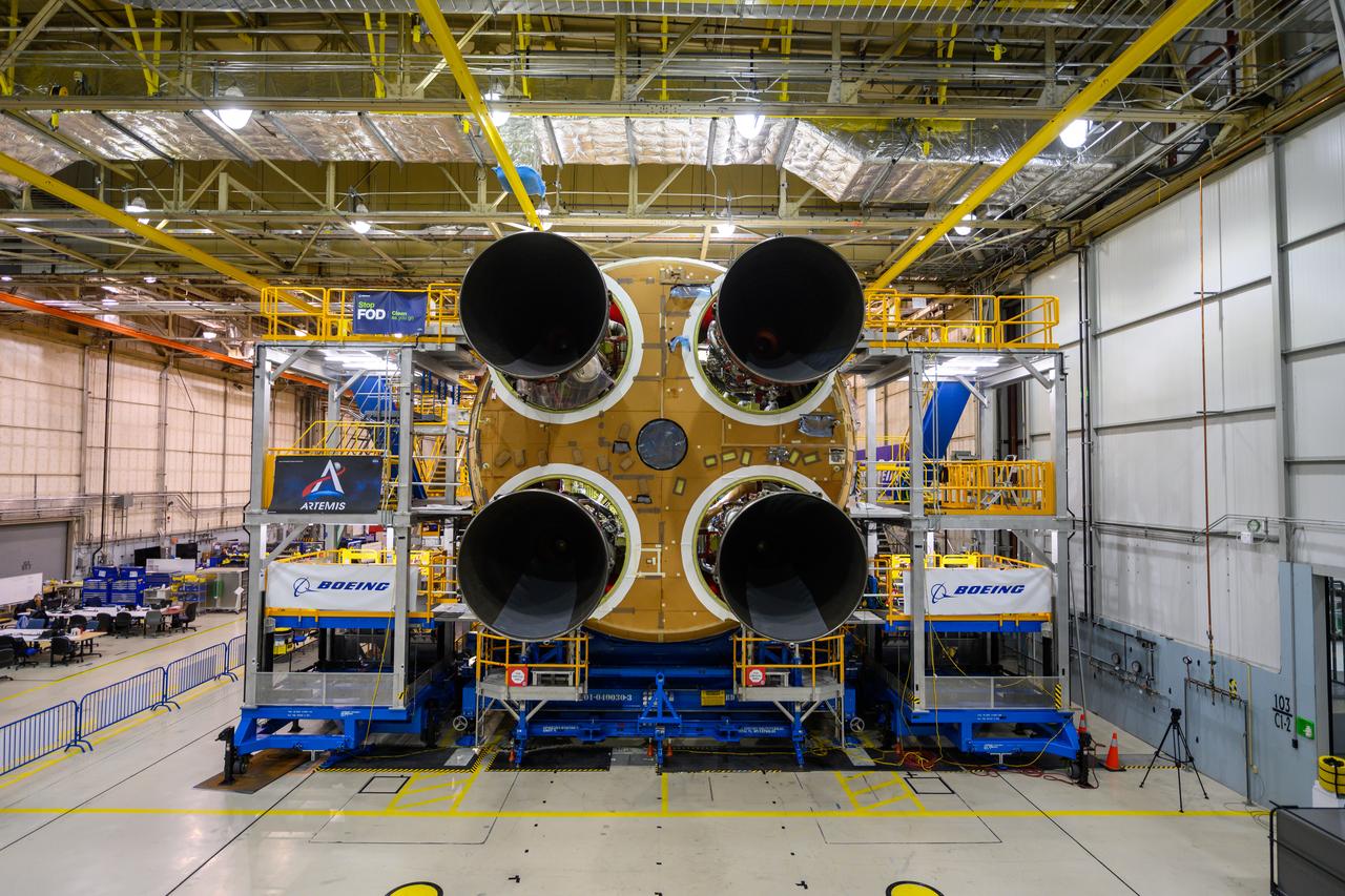
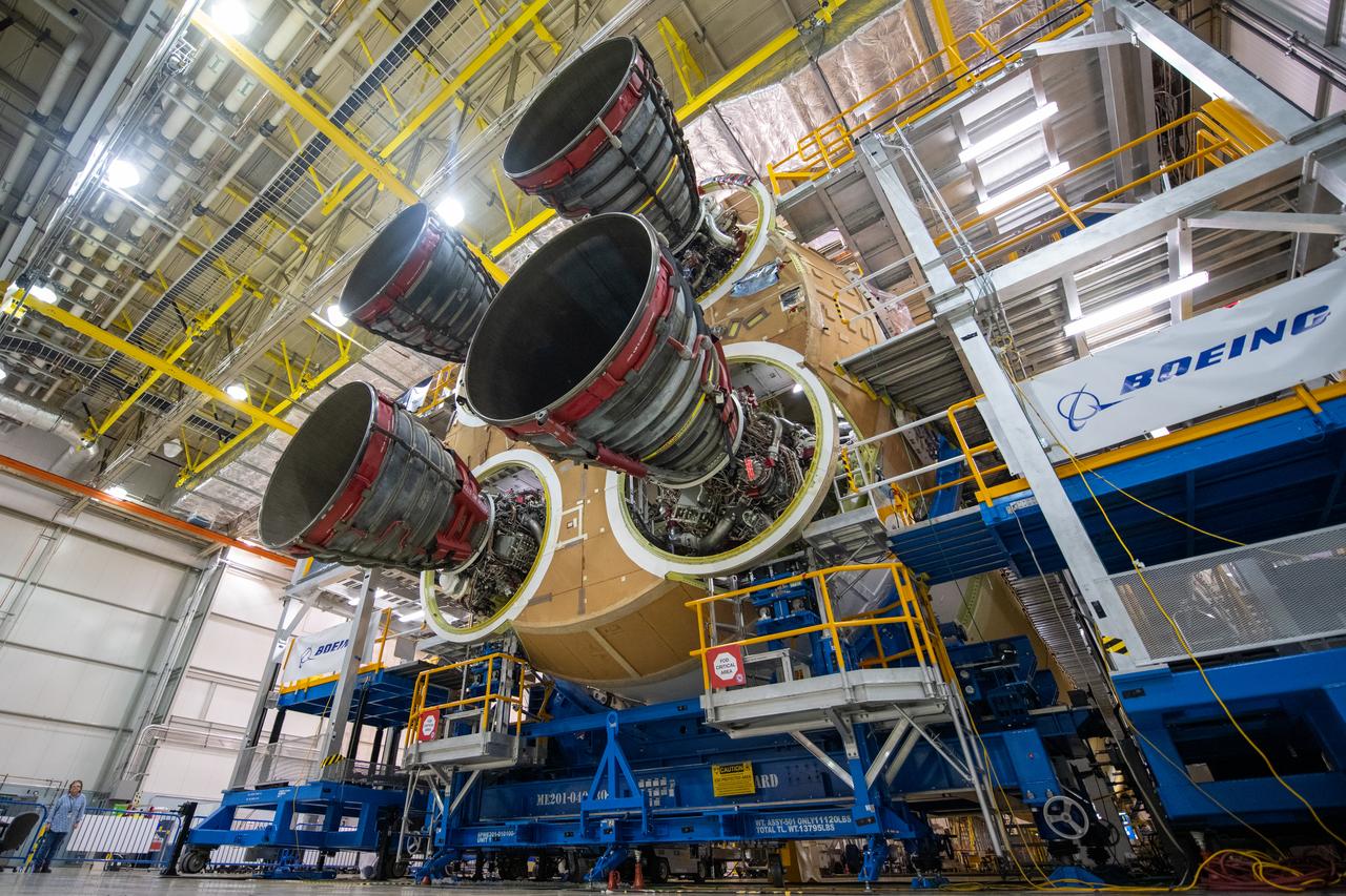
This photo shows all four RS-25 engines attached to the core stage for NASA’s Space Launch System rocket for the agency’s Artemis I mission to the Moon. To complete assembly of the rocket stage, engineers and technicians at NASA’s Michoud Assembly Facility in New Orleans are now integrating the propulsion and electrical systems within the structure. The completed core stage with all four RS-25 engines attached is the largest rocket stage NASA has built since the Saturn V stages for the Apollo Program that first sent Americans to the Moon. The stage, which includes two propellant tanks, provides more than 2 million pounds of thrust to send Artemis I to the Moon. Engineers and technicians attached the fourth RS-25 engine to the rocket stage Nov. 6 just one day after structurally mating the third engine. The first two RS-25 engines were structurally mated to the stage in October. After assembly is complete, crews will conduct an integrated functional test of flight computers, avionics and electrical systems that run throughout the 212-foot-tall core stage in preparation for its completion later this year. This testing is the first time all the flight avionics systems will be tested together to ensure the systems communicate with each other and will perform properly to control the rocket’s flight. Integration of the RS-25 engines to the recently completed core stage structure is a collaborative, multistep process for NASA and its partners Boeing, the core stage lead contractor, and Aerojet Rocketdyne, the RS-25 engines lead contractor. Offering more payload mass, volume capability and energy to speed missions through space, the SLS rocket, along with NASA’s Gateway in lunar orbit and Orion, is part of NASA’s backbone for deep space exploration and the Artemis lunar program. No other rocket is capable of carrying astronauts in Orion around the Moon in a single mission.
This photo shows all four RS-25 engines attached to the core stage for NASA’s Space Launch System rocket for the agency’s Artemis I mission to the Moon. To complete assembly of the rocket stage, engineers and technicians at NASA’s Michoud Assembly Facility in New Orleans are now integrating the propulsion and electrical systems within the structure. The completed core stage with all four RS-25 engines attached is the largest rocket stage NASA has built since the Saturn V stages for the Apollo Program that first sent Americans to the Moon. The stage, which includes two propellant tanks, provides more than 2 million pounds of thrust to send Artemis I to the Moon. Engineers and technicians attached the fourth RS-25 engine to the rocket stage Nov. 6 just one day after structurally mating the third engine. The first two RS-25 engines were structurally mated to the stage in October. After assembly is complete, crews will conduct an integrated functional test of flight computers, avionics and electrical systems that run throughout the 212-foot-tall core stage in preparation for its completion later this year. This testing is the first time all the flight avionics systems will be tested together to ensure the systems communicate with each other and will perform properly to control the rocket’s flight. Integration of the RS-25 engines to the recently completed core stage structure is a collaborative, multistep process for NASA and its partners Boeing, the core stage lead contractor, and Aerojet Rocketdyne, the RS-25 engines lead contractor. Offering more payload mass, volume capability and energy to speed missions through space, the SLS rocket, along with NASA’s Gateway in lunar orbit and Orion, is part of NASA’s backbone for deep space exploration and the Artemis lunar program. No other rocket is capable of carrying astronauts in Orion around the Moon in a single mission.
This photo shows all four RS-25 engines attached to the core stage for NASA’s Space Launch System rocket for the agency’s Artemis I mission to the Moon. To complete assembly of the rocket stage, engineers and technicians at NASA’s Michoud Assembly Facility in New Orleans are now integrating the propulsion and electrical systems within the structure. The completed core stage with all four RS-25 engines attached is the largest rocket stage NASA has built since the Saturn V stages for the Apollo Program that first sent Americans to the Moon. The stage, which includes two propellant tanks, provides more than 2 million pounds of thrust to send Artemis I to the Moon. Engineers and technicians attached the fourth RS-25 engine to the rocket stage Nov. 6 just one day after structurally mating the third engine. The first two RS-25 engines were structurally mated to the stage in October. After assembly is complete, crews will conduct an integrated functional test of flight computers, avionics and electrical systems that run throughout the 212-foot-tall core stage in preparation for its completion later this year. This testing is the first time all the flight avionics systems will be tested together to ensure the systems communicate with each other and will perform properly to control the rocket’s flight. Integration of the RS-25 engines to the recently completed core stage structure is a collaborative, multistep process for NASA and its partners Boeing, the core stage lead contractor, and Aerojet Rocketdyne, the RS-25 engines lead contractor. Offering more payload mass, volume capability and energy to speed missions through space, the SLS rocket, along with NASA’s Gateway in lunar orbit and Orion, is part of NASA’s backbone for deep space exploration and the Artemis lunar program. No other rocket is capable of carrying astronauts in Orion around the Moon in a single mission.
This photo shows all four RS-25 engines attached to the core stage for NASA’s Space Launch System rocket for the agency’s Artemis I mission to the Moon. To complete assembly of the rocket stage, engineers and technicians at NASA’s Michoud Assembly Facility in New Orleans are now integrating the propulsion and electrical systems within the structure. The completed core stage with all four RS-25 engines attached is the largest rocket stage NASA has built since the Saturn V stages for the Apollo Program that first sent Americans to the Moon. The stage, which includes two propellant tanks, provides more than 2 million pounds of thrust to send Artemis I to the Moon. Engineers and technicians attached the fourth RS-25 engine to the rocket stage Nov. 6 just one day after structurally mating the third engine. The first two RS-25 engines were structurally mated to the stage in October. After assembly is complete, crews will conduct an integrated functional test of flight computers, avionics and electrical systems that run throughout the 212-foot-tall core stage in preparation for its completion later this year. This testing is the first time all the flight avionics systems will be tested together to ensure the systems communicate with each other and will perform properly to control the rocket’s flight. Integration of the RS-25 engines to the recently completed core stage structure is a collaborative, multistep process for NASA and its partners Boeing, the core stage lead contractor, and Aerojet Rocketdyne, the RS-25 engines lead contractor. Offering more payload mass, volume capability and energy to speed missions through space, the SLS rocket, along with NASA’s Gateway in lunar orbit and Orion, is part of NASA’s backbone for deep space exploration and the Artemis lunar program. No other rocket is capable of carrying astronauts in Orion around the Moon in a single mission.
This photo shows all four RS-25 engines attached to the core stage for NASA’s Space Launch System rocket for the agency’s Artemis I mission to the Moon. To complete assembly of the rocket stage, engineers and technicians at NASA’s Michoud Assembly Facility in New Orleans are now integrating the propulsion and electrical systems within the structure. The completed core stage with all four RS-25 engines attached is the largest rocket stage NASA has built since the Saturn V stages for the Apollo Program that first sent Americans to the Moon. The stage, which includes two propellant tanks, provides more than 2 million pounds of thrust to send Artemis I to the Moon. Engineers and technicians attached the fourth RS-25 engine to the rocket stage Nov. 6 just one day after structurally mating the third engine. The first two RS-25 engines were structurally mated to the stage in October. After assembly is complete, crews will conduct an integrated functional test of flight computers, avionics and electrical systems that run throughout the 212-foot-tall core stage in preparation for its completion later this year. This testing is the first time all the flight avionics systems will be tested together to ensure the systems communicate with each other and will perform properly to control the rocket’s flight. Integration of the RS-25 engines to the recently completed core stage structure is a collaborative, multistep process for NASA and its partners Boeing, the core stage lead contractor, and Aerojet Rocketdyne, the RS-25 engines lead contractor. Offering more payload mass, volume capability and energy to speed missions through space, the SLS rocket, along with NASA’s Gateway in lunar orbit and Orion, is part of NASA’s backbone for deep space exploration and the Artemis lunar program. No other rocket is capable of carrying astronauts in Orion around the Moon in a single mission.

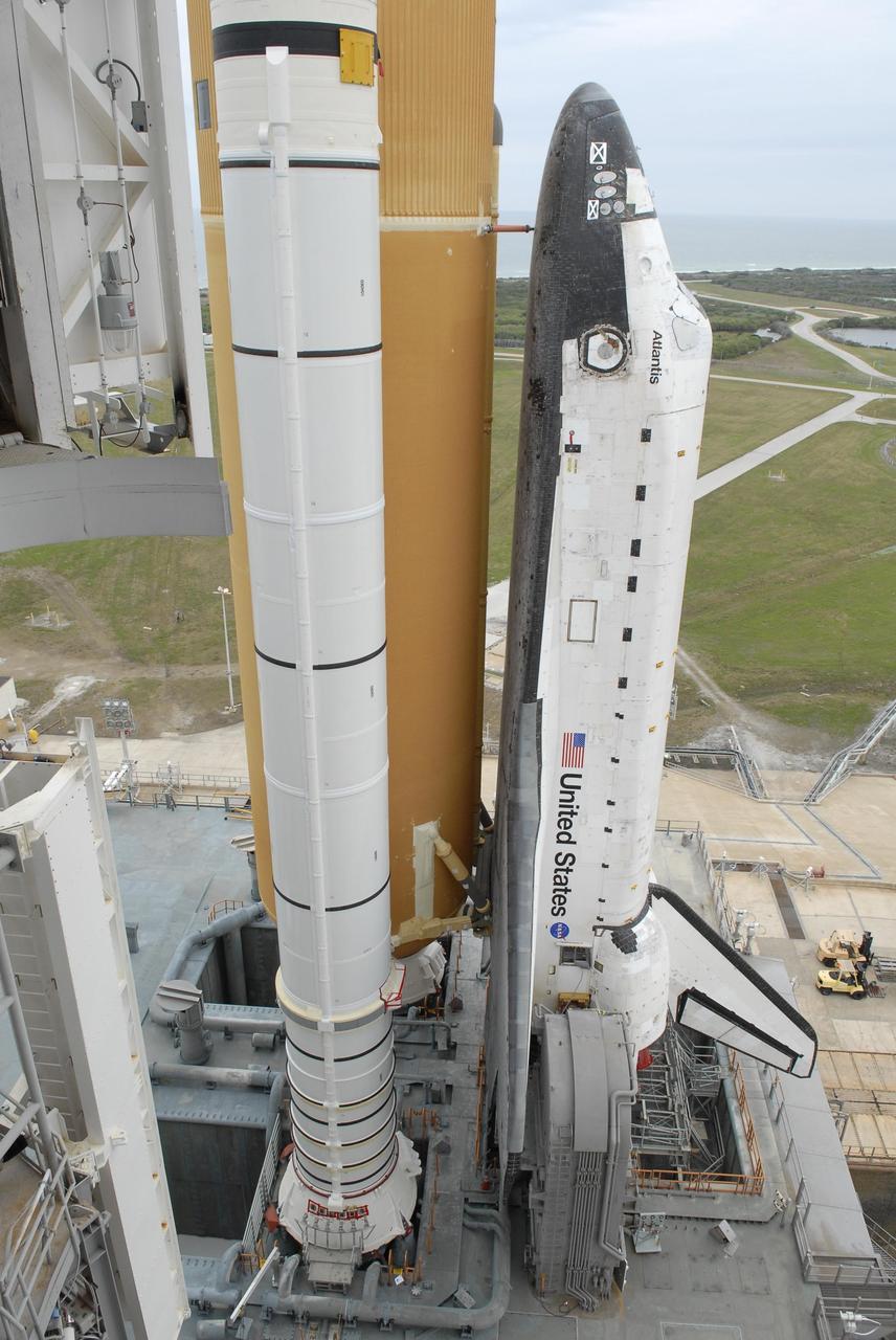
KENNEDY SPACE CENTER, FLA. -- Space Shuttle Atlantis arrives on the hardstand on Launch Pad 39A after a six-hour trek, via the crawler-transporter, from the Vehicle Assembly Building. The first motion out of the assembly building was at 8:19 a.m. In the background is the blue Atlantic Ocean. At left is the box-like structure known as the White Room that sits at the end of the orbiter access arm. The mission payload aboard Space Shuttle Atlantis is the S3/S4 integrated truss structure, along with a third set of solar arrays and batteries. The crew of six astronauts will install the truss to continue assembly of the International Space Station. Launch is targeted for March 15. Photo credit: NASA/Kim Shiflett
Technician’s at NASA’s Michoud Assembly Facility in New Orleans prepared the newly-welded Artemis III mission Orion pressure vessel for shipment to NASA’s Kennedy Space Center’s in Florida, where it later arrived on October 15 at Kennedy’s Neil A. Armstrong Operations and Checkout Building. The pressure vessel, which was joined together using state-of-the-art welding by technicians from lead contractor Lockheed Martin, is the Orion crew module primary structure – the core upon which all other elements of Orion’s crew module are integrated. The structure is a critical element for crew as it holds the pressurized atmosphere astronauts breathe and work in while in the vacuum of deep space. Once transported to Kennedy’s Vehicle Assembly Building high bay, teams will begin integration of the pressure vessel with the Orion spacecraft crew module adapter and other assembly. Photographed on Wednesday, October 13, 2021. Image credit: NASA/Michael DeMocker
Technician’s at NASA’s Michoud Assembly Facility in New Orleans prepared the newly-welded Artemis III mission Orion pressure vessel for shipment to NASA’s Kennedy Space Center’s in Florida, where it later arrived on October 15 at Kennedy’s Neil A. Armstrong Operations and Checkout Building. The pressure vessel, which was joined together using state-of-the-art welding by technicians from lead contractor Lockheed Martin, is the Orion crew module primary structure – the core upon which all other elements of Orion’s crew module are integrated. The structure is a critical element for crew as it holds the pressurized atmosphere astronauts breathe and work in while in the vacuum of deep space. Once transported to Kennedy’s Vehicle Assembly Building high bay, teams will begin integration of the pressure vessel with the Orion spacecraft crew module adapter and other assembly. Photographed on Wednesday, October 13, 2021. Image credit: NASA/Michael DeMocker
Technician’s at NASA’s Michoud Assembly Facility in New Orleans prepared the newly-welded Artemis III mission Orion pressure vessel for shipment to NASA’s Kennedy Space Center’s in Florida, where it later arrived on October 15 at Kennedy’s Neil A. Armstrong Operations and Checkout Building. The pressure vessel, which was joined together using state-of-the-art welding by technicians from lead contractor Lockheed Martin, is the Orion crew module primary structure – the core upon which all other elements of Orion’s crew module are integrated. The structure is a critical element for crew as it holds the pressurized atmosphere astronauts breathe and work in while in the vacuum of deep space. Once transported to Kennedy’s Vehicle Assembly Building high bay, teams will begin integration of the pressure vessel with the Orion spacecraft crew module adapter and other assembly. Photographed on Wednesday, October 13, 2021. Image credit: NASA/Michael DeMocker
Technician’s at NASA’s Michoud Assembly Facility in New Orleans prepared the newly-welded Artemis III mission Orion pressure vessel for shipment to NASA’s Kennedy Space Center’s in Florida, where it later arrived on October 15 at Kennedy’s Neil A. Armstrong Operations and Checkout Building. The pressure vessel, which was joined together using state-of-the-art welding by technicians from lead contractor Lockheed Martin, is the Orion crew module primary structure – the core upon which all other elements of Orion’s crew module are integrated. The structure is a critical element for crew as it holds the pressurized atmosphere astronauts breathe and work in while in the vacuum of deep space. Once transported to Kennedy’s Vehicle Assembly Building high bay, teams will begin integration of the pressure vessel with the Orion spacecraft crew module adapter and other assembly. Photographed on Wednesday, October 13, 2021. Image credit: NASA/Michael DeMocker
Technician’s at NASA’s Michoud Assembly Facility in New Orleans prepared the newly-welded Artemis III mission Orion pressure vessel for shipment to NASA’s Kennedy Space Center’s in Florida, where it later arrived on October 15 at Kennedy’s Neil A. Armstrong Operations and Checkout Building. The pressure vessel, which was joined together using state-of-the-art welding by technicians from lead contractor Lockheed Martin, is the Orion crew module primary structure – the core upon which all other elements of Orion’s crew module are integrated. The structure is a critical element for crew as it holds the pressurized atmosphere astronauts breathe and work in while in the vacuum of deep space. Once transported to Kennedy’s Vehicle Assembly Building high bay, teams will begin integration of the pressure vessel with the Orion spacecraft crew module adapter and other assembly. Photographed on Wednesday, October 13, 2021. Image credit: NASA/Michael DeMocker
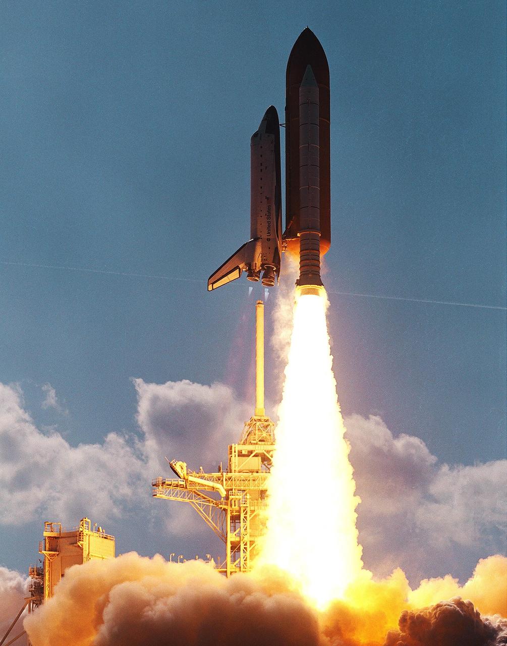
KENNEDY SPACE CENTER, FLA. - Space Shuttle Atlantis clears the lightning mast as it hurtles into the afternoon sky from Launch Pad 39B on mission STS-110. The mast is on the top of the Fixed Service Structure. Flames from the solid rocket booster look like an inverted torch. Liftoff occurred at 4:44:19 p.m. EDT (20:41:19 GMT). Carrying the S0 Integrated Truss Structure and Mobile Transporter, STS-110 is the 13th assembly flight to the International Space Station
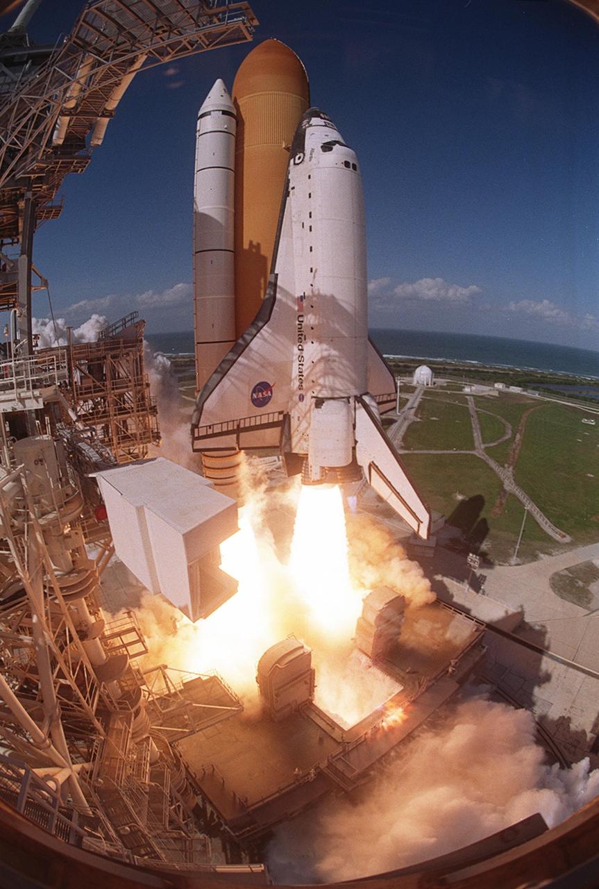
KENNEDY SPACE CENTER, FLA. - A fish eye view captures the liftoff of Space Shuttle Atlantis from Launch Pad 39B. At left is the Fixed Service Structure and below the Shuttle is the Mobile Launcher Platform. In the background is the Atlantic Ocean. Liftoff of Atlantis on mission STS-110 occurred at 4:44:19 p.m. EDT (20:41:19 GMT). Carrying the S0 Integrated Truss Structure and Mobile Transporter, STS-110 is the 13th assembly flight to the International Space Station
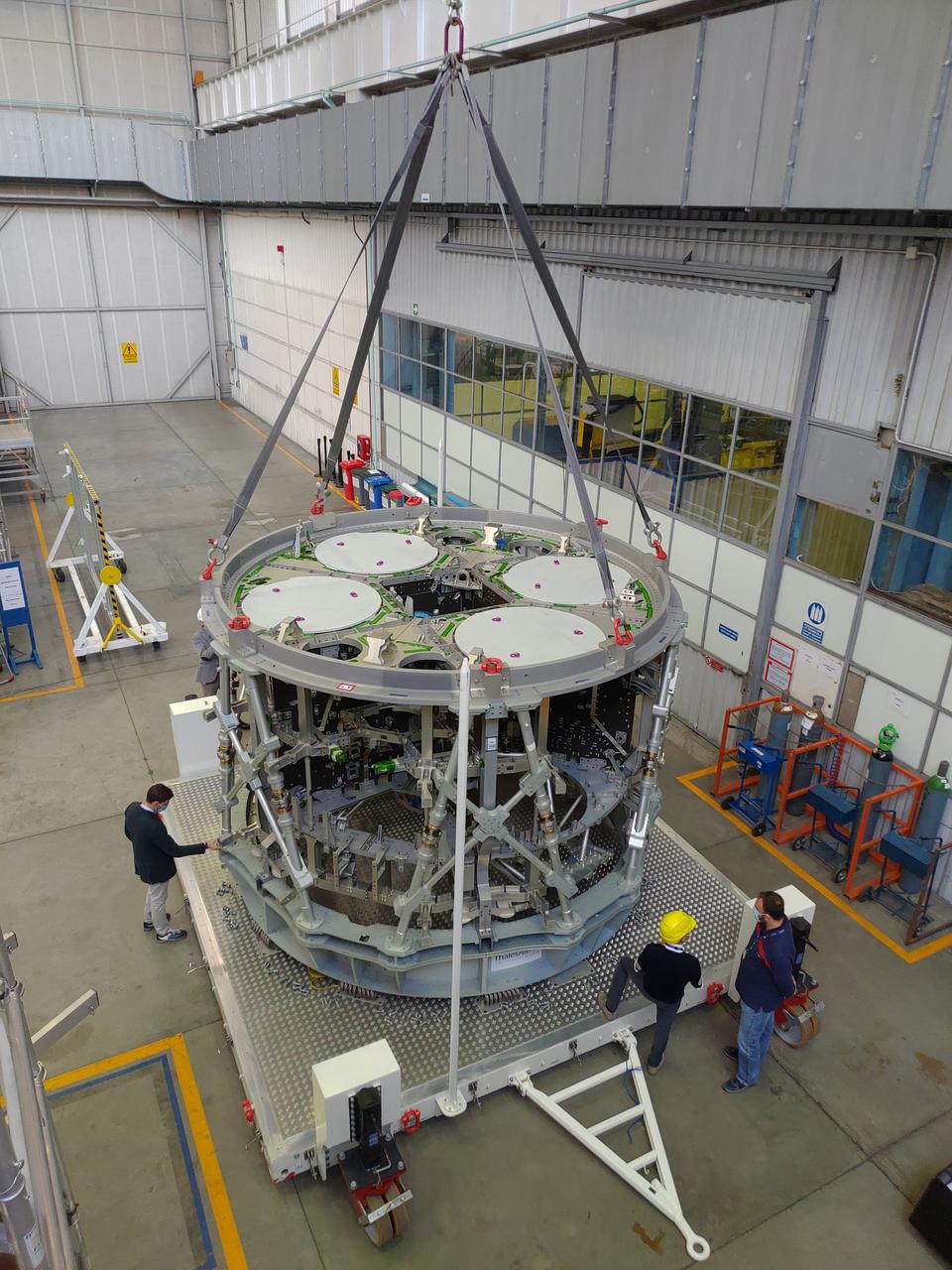
The ESA service module primary structure, which will propel Orion on the Artemis III flight carrying astronauts to land on the surface of the Moon, is ready to ship from Thales Alenia Space in Turin, Italy to Airbus in Bremen, Germany. Stefano Rossi, Thales Alenia Space Manufacturing Manager, leads the operation of the transfer of the service module structure to the transportation container on Sept. 30, 2020. Airbus will perform final assembly on the service module ahead of shipment to Kennedy Space Center where it will be integrated with the rest of the Orion spacecraft.
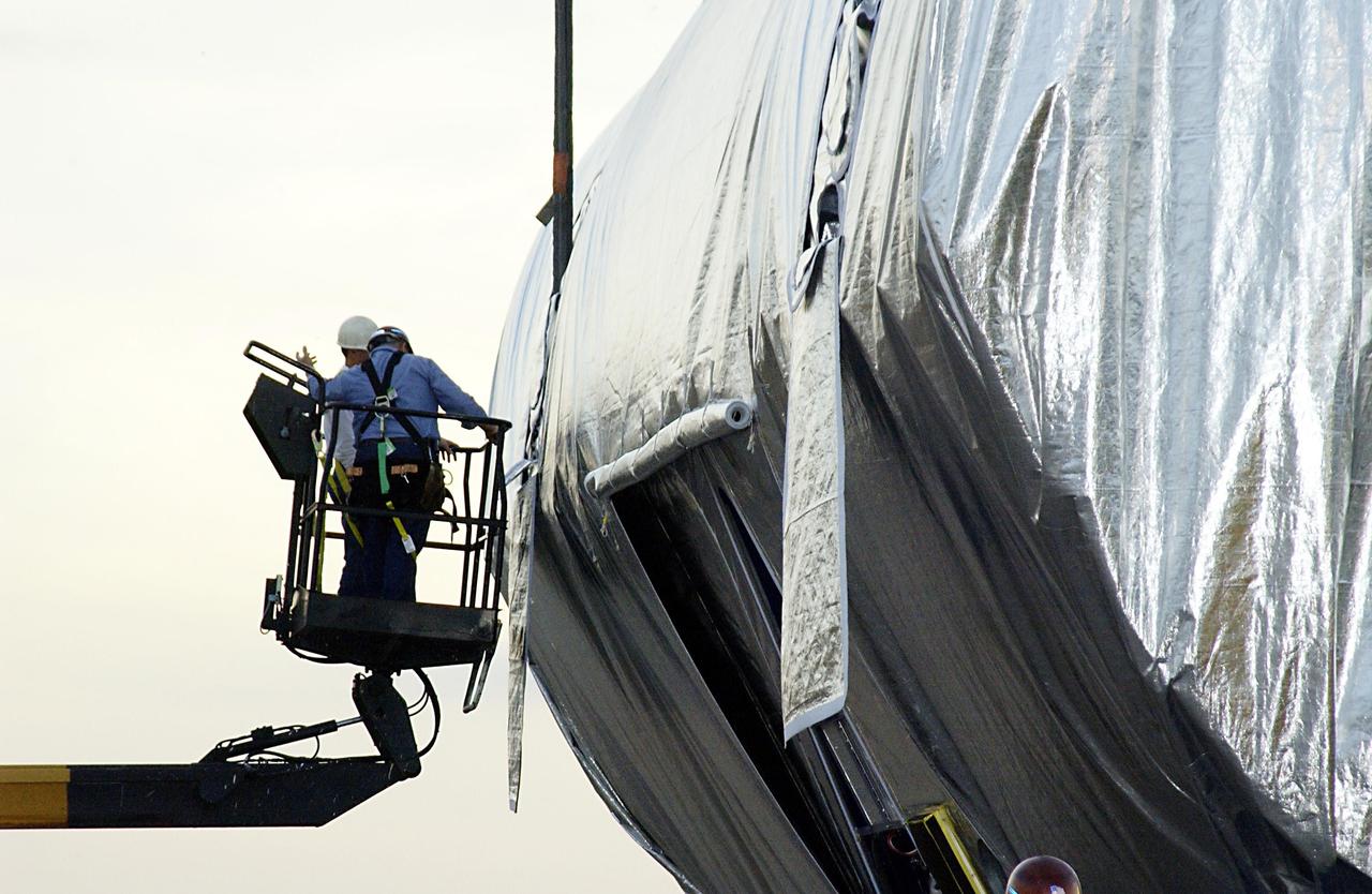
KENNEDY SPACE CENTER, FLA. -- In the Space Station Processing Facility, workers begin uncovering the Long Spacer (LS), the second and final piece of the S6 Integrated Truss Segment. Both the LS and the S6 Integrated Equipment Assembly (IEA) will undergo inspections and verifications tests to prepare them for flight to the International Space Station in early 2004. Although separate for now, the two segments will be integrated and fly as one on mission STS-119. Together the two pieces weigh 26,000 pounds and measure 45 feet long. The S6 is the 11th and final piece of the Station's Integrated Truss Structure, which will measure more than 300 feet in all. .
KENNEDY SPACE CENTER, FLA. -- In the Space Station Processing Facility, workers finish uncovering the Long Spacer (LS), the second and final piece of the S6 Integrated Truss Segment. Both the LS and the S6 Integrated Equipment Assembly (IEA) will undergo inspections and verifications tests to prepare them for flight to the International Space Station in early 2004. Although separate for now, the two segments will be integrated and fly as one on mission STS-119. Together the two pieces weigh 26,000 pounds and measure 45 feet long. The S6 is the 11th and final piece of the Station's Integrated Truss Structure, which will measure more than 300 feet in all. .
KENNEDY SPACE CENTER, FLA. -- In the Space Station Processing Facility, workers begin uncovering the Long Spacer (LS), the second and final piece of the S6 Integrated Truss Segment. Both the LS and the S6 Integrated Equipment Assembly (IEA) will undergo inspections and verifications tests to prepare them for flight to the International Space Station in early 2004. Although separate for now, the two segments will be integrated and fly as one on mission STS-119. Together the two pieces weigh 26,000 pounds and measure 45 feet long. The S6 is the 11th and final piece of the Station's Integrated Truss Structure, which will measure more than 300 feet in all. .
KENNEDY SPACE CENTER, FLA. -- In the Space Station Processing Facility, workers begin uncovering the Long Spacer (LS), the second and final piece of the S6 Integrated Truss Segment. Both the LS and the S6 Integrated Equipment Assembly (IEA) will undergo inspections and verifications tests to prepare them for flight to the International Space Station in early 2004. Although separate for now, the two segments will be integrated and fly as one on mission STS-119. Together the two pieces weigh 26,000 pounds and measure 45 feet long. The S6 is the 11th and final piece of the Station's Integrated Truss Structure, which will measure more than 300 feet in all. .

KENNEDY SPACE CENTER, FLA. -- In the Space Station Processing Facility, a worker begins uncovering the Long Spacer (LS), the second and final piece of the S6 Integrated Truss Segment. Both the LS and the S6 Integrated Equipment Assembly (IEA) will undergo inspections and verifications tests to prepare them for flight to the International Space Station in early 2004. Although separate for now, the two segments will be integrated and fly as one on mission STS-119. Together the two pieces weigh 26,000 pounds and measure 45 feet long. The S6 is the 11th and final piece of the Station's Integrated Truss Structure, which will measure more than 300 feet in all. .

KENNEDY SPACE CENTER, FLA. -- Flags are flying at the entrance to Launch Pad 39A, where Space Shuttle Atlantis has come to a stop. At left are the rotating and fixed service structures; at right is the 300-gallon water tower. The shuttle has spent six hours rolling out to Pad 39A, leaving the Vehicle Assembly Building at 8:19 a.m. The mission payload aboard Space Shuttle Atlantis is the S3/S4 integrated truss structure, along with a third set of solar arrays and batteries. The crew of six astronauts will install the truss to continue assembly of the International Space Station. Launch is targeted for March 15. Photo credit: NASA/Ken Thornsley
KENNEDY SPACE CENTER, FLA. -- Lined up on the horizon are Space Shuttle Atlantis, the rotating and fixed service structures of Launch Pad 39A, Launch Pad 39B, and the 300-gallon water tower of Pad 39A. The shuttle has spent six hours rolling out to Pad 39A, leaving the Vehicle Assembly Building at 8:19 a.m. The body of water in the foreground is the Banana River. The mission payload aboard Space Shuttle Atlantis is the S3/S4 integrated truss structure, along with a third set of solar arrays and batteries. The crew of six astronauts will install the truss to continue assembly of the International Space Station. Launch is targeted for March 15. Photo credit: NASA/Ken Thornsley
KENNEDY SPACE CENTER, FLA. -- The Integrated Equipment Assembly (IEA), one of two major components of the Starboard 6 (S6) truss segment for the International Space Station (ISS), is offloaded onto a cargo transporter following its arrival at the Shuttle Landing Facility. The IEA will be joined to its companion piece, the Long Spacer, before launch early in 2004. The S6 truss segment will be the 11th and final piece of the Station's Integrated Truss Structure and will support the fourth and final set of solar arrays, batteries, and electronics.
KENNEDY SPACE CENTER, FLA. -- The Integrated Equipment Assembly (IEA), one of two major components of the Starboard 6 (S6) truss segment for the International Space Station (ISS), is offloaded onto a cargo transporter following its arrival at the Shuttle Landing Facility. The IEA will be joined to its companion piece, the Long Spacer, before launch early in 2004. The S6 truss segment will be the 11th and final piece of the Station's Integrated Truss Structure and will support the fourth and final set of solar arrays, batteries, and electronics.
KENNEDY SPACE CENTER, FLA. -- The Integrated Equipment Assembly (IEA), one of two major components of the Starboard 6 (S6) truss segment for the International Space Station (ISS), sits on a cargo transporter following its arrival at the Shuttle Landing Facility. The IEA will be joined to its companion piece, the Long Spacer, before launch early in 2004. The S6 truss segment will be the 11th and final piece of the Station's Integrated Truss Structure and will support the fourth and final set of solar arrays, batteries, and electronics.
KENNEDY SPACE CENTER, FLA. -- KSC technicians supervise the offloading of the Integrated Equipment Assembly (IEA), one of two major components of the Starboard 6 (S6) truss segment for the International Space Station (ISS), onto a cargo transporter following its arrival at the Shuttle Landing Facility. The IEA will be joined to its companion piece, the Long Spacer, before launch early in 2004. The S6 truss segment will be the 11th and final piece of the Station's Integrated Truss Structure and will support the fourth and final set of solar arrays, batteries, and electronics.

KENNEDY SPACE CENTER, Fla. -- Nearby waters capture the brilliance of Space Shuttle Endeavour's flames as it leaps off Launch Pad 39B toward space. Liftoff of Endeavour occurred at 10:06:01 p.m. EST. Endeavour is transporting the P6 Integrated Truss Structure that comprises Solar Array Wing-3 and the Integrated Electronic Assembly, to provide power to the Space Station. The 11-day mission includes two spacewalks to complete the solar array connections. Endeavour is expected to land Dec. 11 at 6:19 p.m. EST
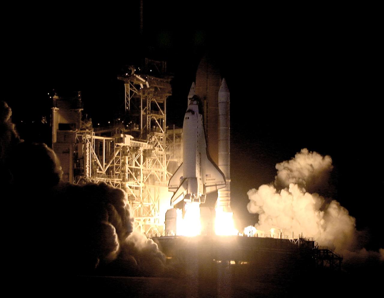
KENNEDY SPACE CENTER, Fla. -- In a perfect liftoff at 10:06:01 p.m. EST, Space Shuttle Endeavour, with its crew of five, roars into space in a burst of light. This sixth construction flight to the International Space Station is transporting the P6 Integrated Truss Structure that comprises Solar Array Wing-3 and the Integrated Electronic Assembly, to provide power to the Space Station. The 11-day mission includes two spacewalks to complete the solar array connections. Endeavour is expected to land Dec. 11 at 6:19 p.m. EST
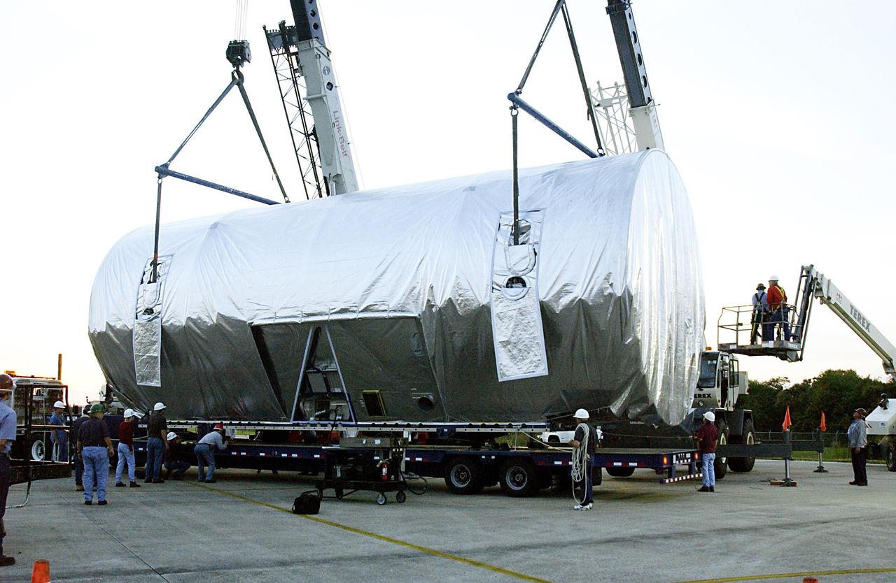
KENNEDY SPACE CENTER, FLA. -- KSC technicians supervise the transfer of the Integrated Equipment Assembly (IEA), one of two major components of the Starboard 6 (S6) truss segment for the International Space Station (ISS), onto a cargo transporter following its arrival at the Shuttle Landing Facility. The IEA will be joined to its companion piece, the Long Spacer, before launch early in 2004. The S6 truss segment will be the 11th and final piece of the Station's Integrated Truss Structure and will support the fourth and final set of solar arrays, batteries, and electronics.
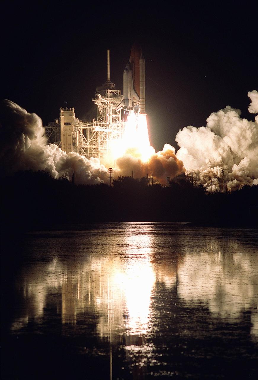
KENNEDY SPACE CENTER, Fla. -- Nearby waters capture the brilliance of Space Shuttle Endeavour's flames as it leaps off Launch Pad 39B toward space. Liftoff of Endeavour occurred at 10:06:01 p.m. EST. Endeavour is transporting the P6 Integrated Truss Structure that comprises Solar Array Wing-3 and the Integrated Electronic Assembly, to provide power to the Space Station. The 11-day mission includes two spacewalks to complete the solar array connections. Endeavour is expected to land Dec. 11 at 6:19 p.m. EST
KENNEDY SPACE CENTER, FLA. -- In the Orbiter Processing Facility, STS-110 Commander Michael Bloomfield checks out a window in the cockpit of Atlantis during Crew Equipment Integration Test activities. The mission, 13th assembly flight to the International Space Station, includes the Integrated Truss Structure S0. The ITS S0 is the center segment on the Space Station, part of the 300-foot (91-meter) truss attached to the U.S. Lab. By assembly completion, four more truss segments will attach to either side of the S0 truss. STS-110 is scheduled to launch April 4, 2002
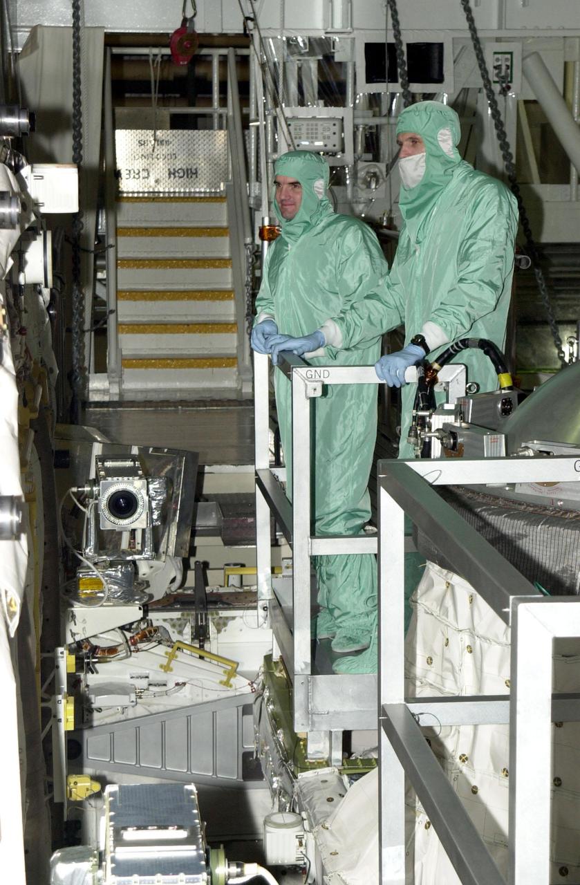
KENNEDY SPACE CENTER, FLA. -- In the Orbiter Processing Facility, STS-110 Mission Specialists Rex Walheim (left) and Steven Smith (right) look over the payload bay of Atlantis during Crew Equipment Integration Test activities, which include familiarization with the vehicle and payload. . The mission, 13th assembly flight to the International Space Station, includes the Integrated Truss Structure S0. The ITS S0 is the center segment on the Space Station, part of the 300-foot (91-meter) truss attached to the U.S. Lab. By assembly completion, four more truss segments will attach to either side of the S0 truss. STS-110 is scheduled to launch April 4, 2002

KENNEDY SPACE CENTER, FLA. -- In the Orbiter Processing Facility, STS-110 crew members look over the payload bay of Atlantis during Crew Equipment Integration Test activities, which include familiarization with the vehicle and payload. From left are Mission Specialist Jerry Ross, a technician, and Mission Specialist Lee Morin. The mission, 13th assembly flight to the International Space Station, includes the Integrated Truss Structure S0. The ITS S0 is the center segment on the Space Station, part of the 300-foot (91-meter) truss attached to the U.S. Lab. By assembly completion, four more truss segments will attach to either side of the S0 truss. STS-110 is scheduled to launch April 4, 2002

KENNEDY SPACE CENTER, FLA. -- In the Orbiter Processing Facility, STS-110 Mission Specialists Jerry Ross (upper right) and Lee Morin (lower right) check out the payload bay of Atlantis during Crew Equipment Integration Test activities, which include familiarization with the vehicle and payload. . The mission, 13th assembly flight to the International Space Station, includes the Integrated Truss Structure S0. The ITS S0 is the center segment on the Space Station, part of the 300-foot (91-meter) truss attached to the U.S. Lab. By assembly completion, four more truss segments will attach to either side of the S0 truss. STS-110 is scheduled to launch April 4, 2002
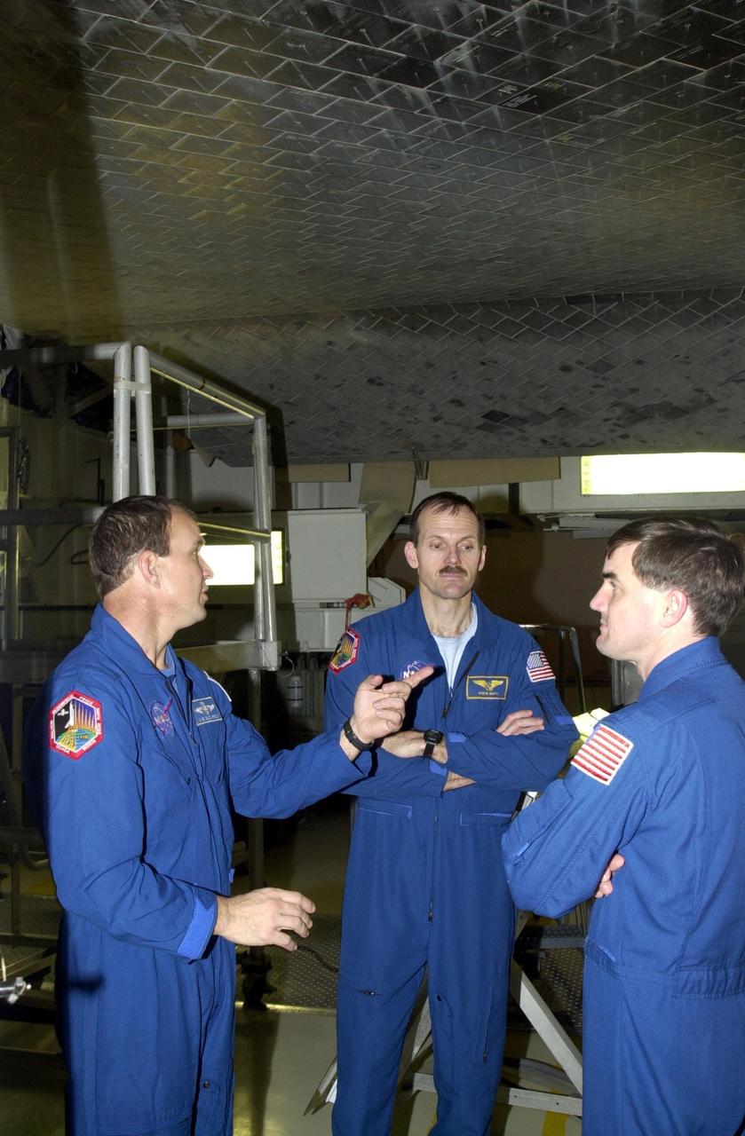
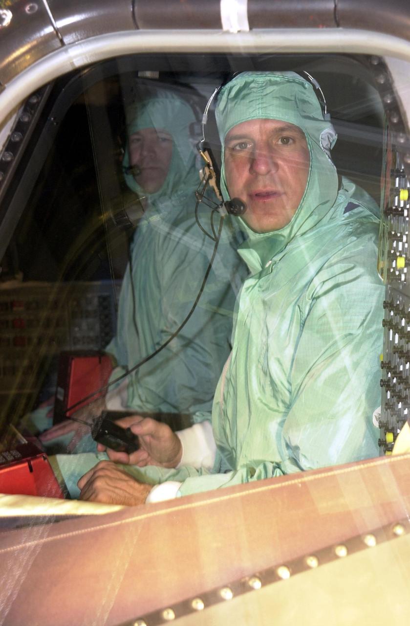
KENNEDY SPACE CENTER, FLA. -- Standing underneath the orbiter Atlantis in the Orbiter Processing Facility are STS-110 Commander Michael Bloomfield and Mission Specialists Steven Smith and Rex Walheim. They and other crew members are taking part in Crew Equipment Integration Test activities, which include familiarization with the vehicle and payload. The mission, 13th assembly flight to the International Space Station, includes the Integrated Truss Structure S0. The ITS S0 is the center segment on the Space Station, part of the 300-foot (91-meter) truss attached to the U.S. Lab. By assembly completion, four more truss segments will attach to either side of the S0 truss. STS-110 is scheduled to launch April 4, 2002
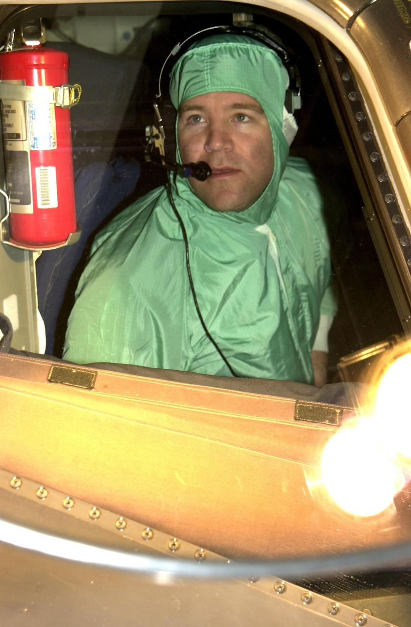
KENNEDY SPACE CENTER, FLA. -- In the Orbiter Processing Facility, STS-110 Pilot Stephen Frick checks a window in the cockpit of Atlantis during Crew Equipment Integration Test activities. The mission, 13th assembly flight to the International Space Station, includes the Integrated Truss Structure S0. The ITS S0 is the center segment on the Space Station, part of the 300-foot (91-meter) truss attached to the U.S. Lab. By assembly completion, four more truss segments will attach to either side of the S0 truss. STS-110 is scheduled to launch April 4, 2002

This photo shows the second RS-25 engine attached to the core stage for NASA’s Space Launch System rocket for the agency’s Artemis I mission to the Moon. Engineers and technicians at NASA’s Michoud Assembly Facility in New Orleans structurally mated the second of four engines to the stage on Oct. 30 and are currently integrating the propulsion and electrical systems within the structure to complete the installation. Integration of the RS-25 engines to the recently completed core stage structure is a collaborative, multistep process for NASA and its partners Boeing, the core stage lead contractor, and Aerojet Rocketdyne, the RS-25 engines lead contractor. The four RS-25 engines for Artemis I are modified heritage flight hardware from the Space Shuttle Program, ensuring high performance and reliability to power NASA’s next generation lunar missions. Each engine also has a special identification number, and NASA keeps a history of which engines are used on each mission. The second engine, Engine 2045, has flown on several shuttle missions, including the mission that returned NASA astronaut John Glenn to space in 1998 as well as the first and only shuttle launch to occur on Independence Day in 2006.

This photo shows the third of four RS-25 engines attached to the core stage for NASA’s Space Launch System rocket for the agency’s Artemis I mission to the Moon. NASA, Boeing and Aerojet Rocketdyne crews at NASA’s Michoud Assembly Facility in New Orleans attached the third RS-25 engine to the core stage for the SLS rocket on Nov. 5. The engine is one of four RS-25 engines that will provide more than 2 million pounds of thrust to send Artemis I, the first mission of SLS and NASA’s Orion spacecraft, to the Moon. The first two RS-25 engines were structurally mated to the stage in October. Following the mate, engineers and technicians will integrate the propulsion and electrical systems within the structures to complete the installation. Integration of the RS-25 engines to the recently completed core stage structure is a collaborative, multistep process for NASA and its partners Boeing, the core stage lead contractor, and Aerojet Rocketdyne, the RS-25 engines lead contractor. Offering more payload mass, volume capability and energy to speed missions through space, the SLS rocket, along with NASA’s Gateway in lunar orbit and Orion, is part of NASA’s backbone for deep space exploration and the Artemis lunar program. No other rocket is capable of carrying astronauts in Orion around the Moon in a single mission.

Teams at NASA’s Kennedy Space Center in Florida installed four “quad pods” around the Artemis III core stage engine section inside the spaceport’s Space Systems Processing Facility on Tuesday, Sept. 10, 2024. These structures are used to support the engine assembly during operations. The engine section will be transferred to the NASA Kennedy’s Vehicle Assembly Building for final integration.
Teams at NASA’s Kennedy Space Center in Florida installed four “quad pods” around the Artemis III core stage engine section inside the spaceport’s Space Systems Processing Facility on Tuesday, Sept. 10, 2024. These structures are used to support the engine assembly during operations. The engine section will be transferred to the NASA Kennedy’s Vehicle Assembly Building for final integration.
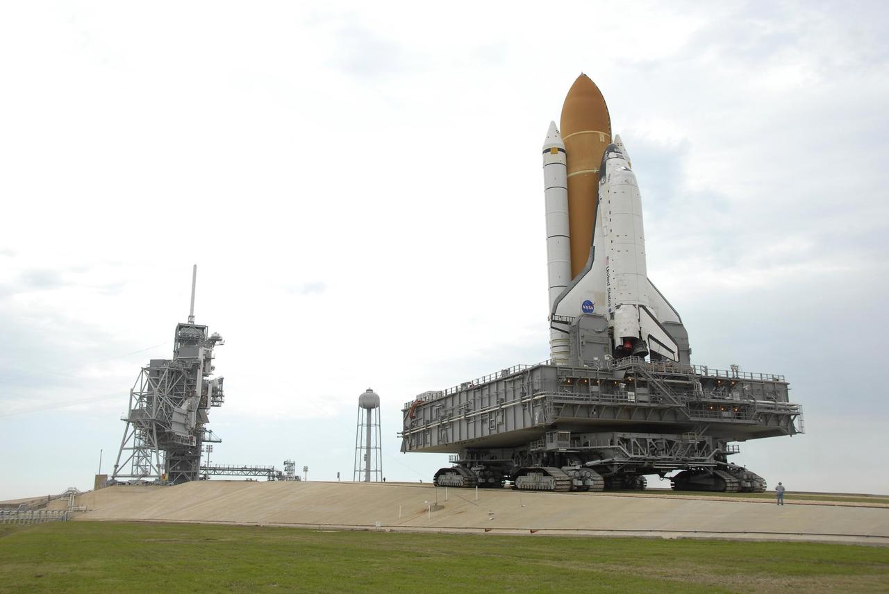
KENNEDY SPACE CENTER, FLA. -- Space Shuttle Atlantis, atop the mobile launcher platform and crawler-transporter, slowly makes its way up the ramp to the hardstand on Launch Pad 39A. At left is the fixed service structure, with the 80-foot lightning mast on top, and the open rotating service structure. Between them is the water tower, containing 300,000 gallons of water used for sound suppression at liftoff. First motion of the shuttle out of the Vehicle Assembly Building was at 8:19 a.m. The 3.4-mile trip to the pad along the crawlerway takes about 6 hours. The mission payload aboard Space Shuttle Atlantis is the S3/S4 integrated truss structure, along with a third set of solar arrays and batteries. The crew of six astronauts will install the truss to continue assembly of the International Space Station. Launch is targeted for March 15. Photo credit: NASA/Kim Shiflett
KENNEDY SPACE CENTER, FLA. -- Space Shuttle Atlantis arrives on the hardstand on Launch Pad 39A after a six-hour trek, via the crawler-transporter, from the Vehicle Assembly Building. The first motion out of the assembly building was at 8:19 a.m. The mission payload aboard Space Shuttle Atlantis is the S3/S4 integrated truss structure, along with a third set of solar arrays and batteries. The crew of six astronauts will install the truss to continue assembly of the International Space Station. Launch is targeted for March 15. Photo credit: NASA/Kim Shiflett

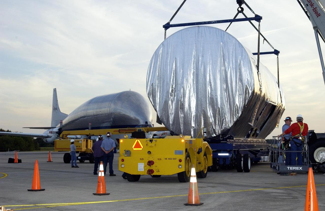
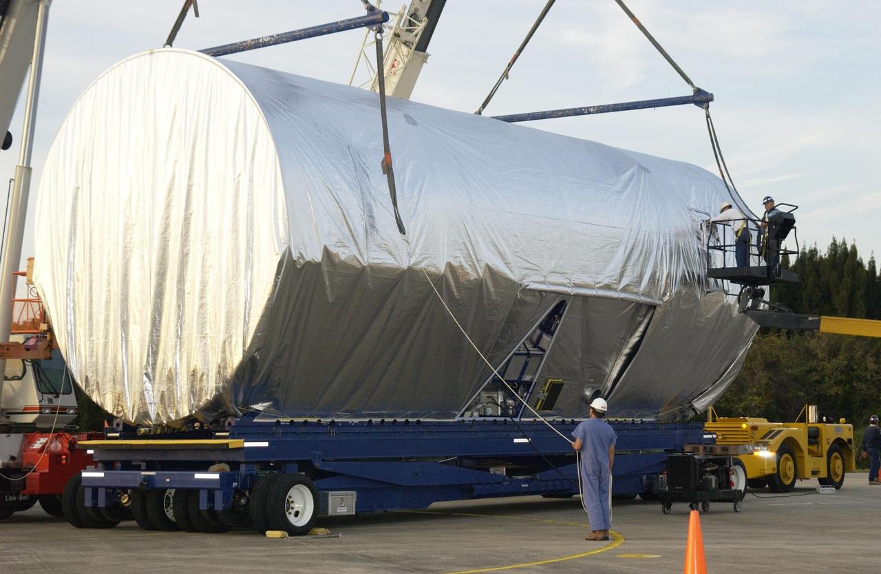
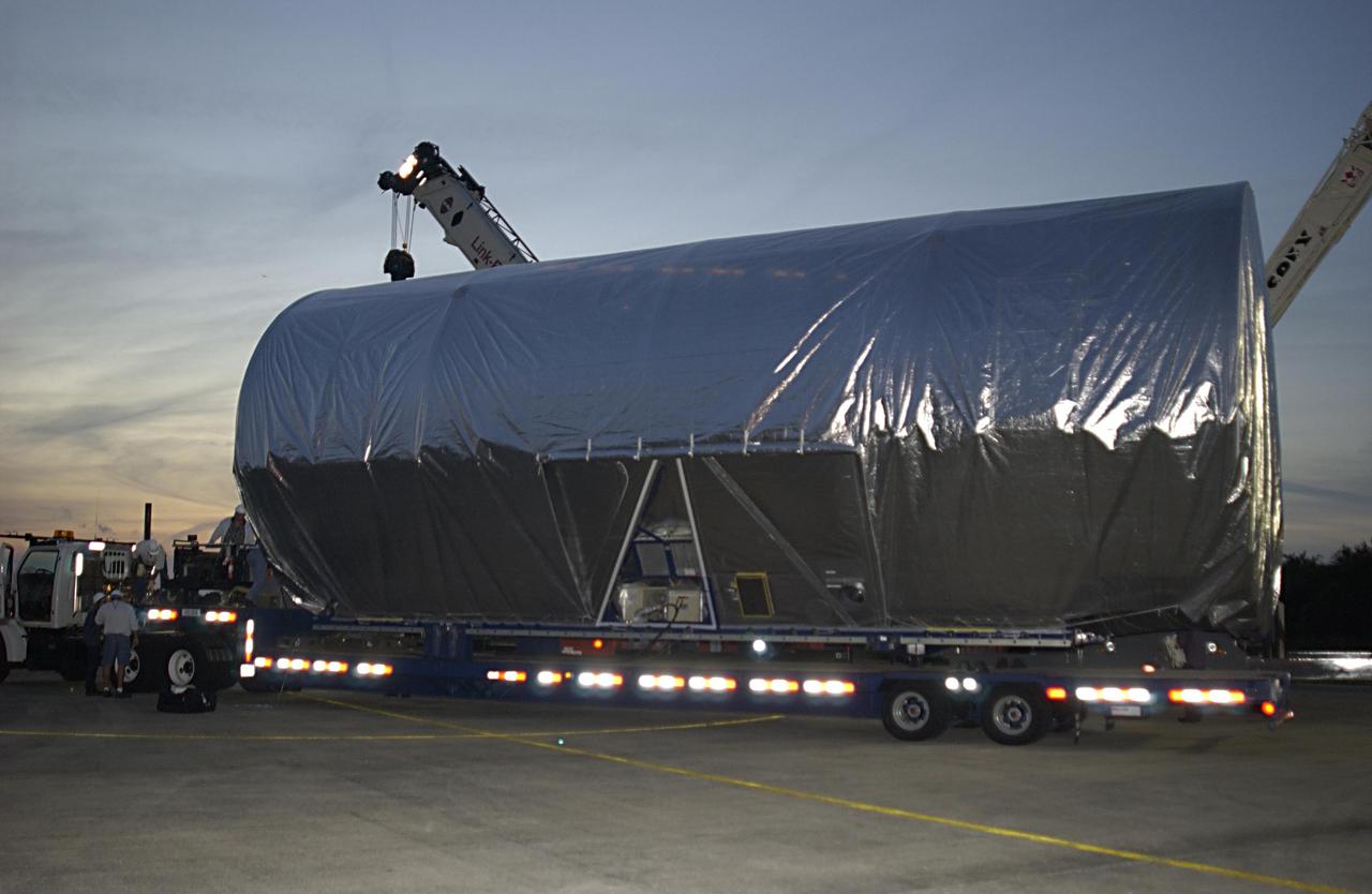
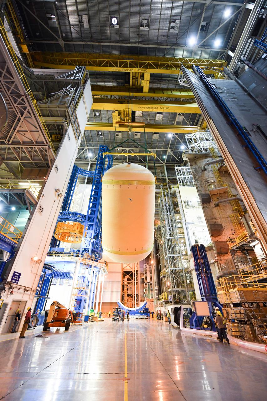
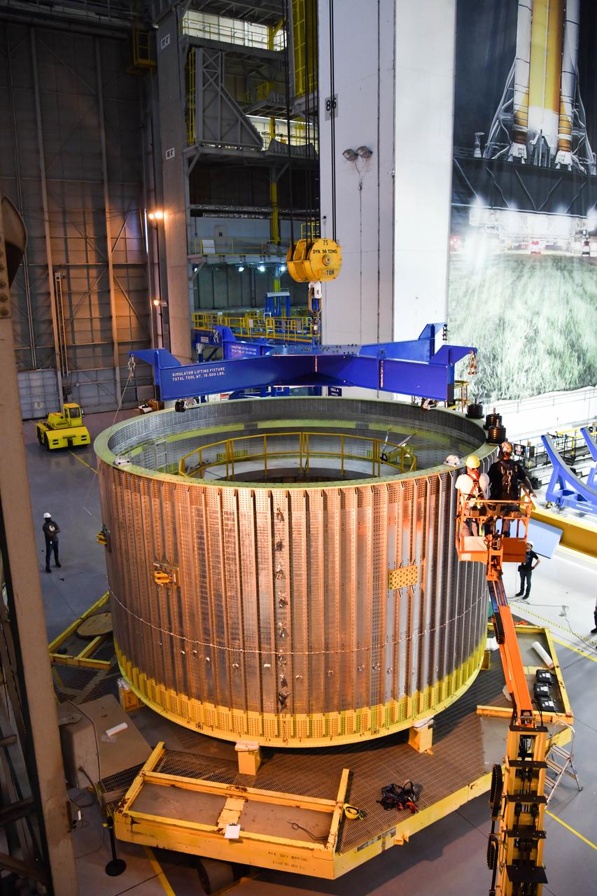
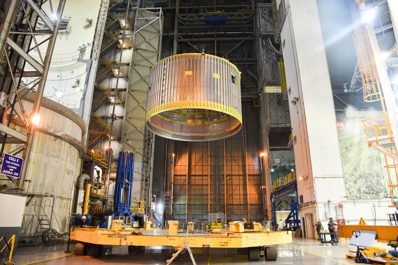
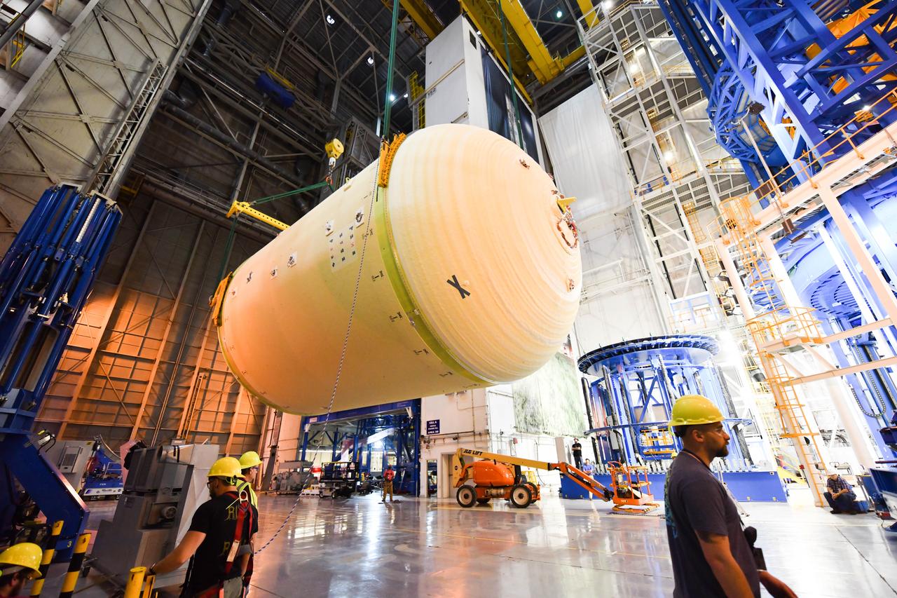
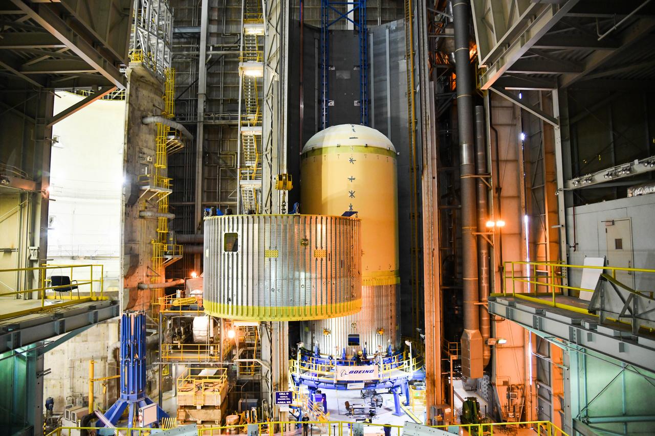
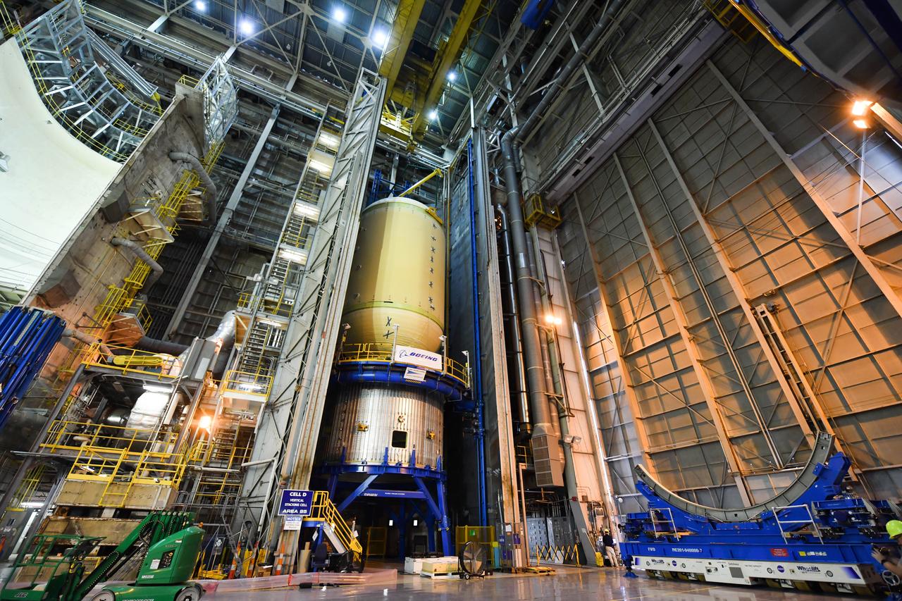
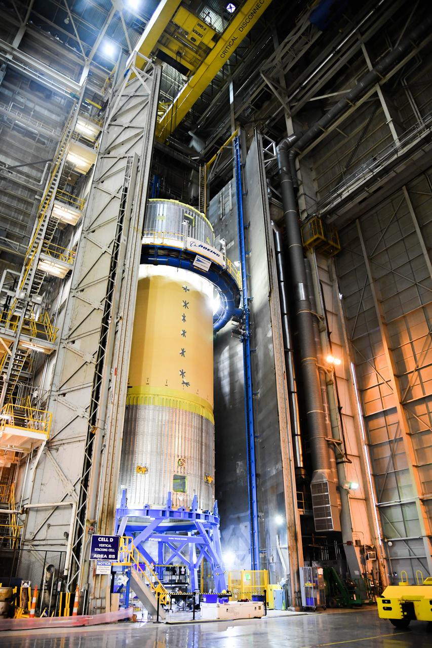
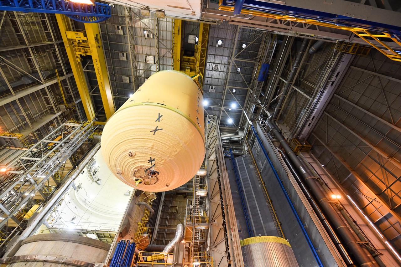
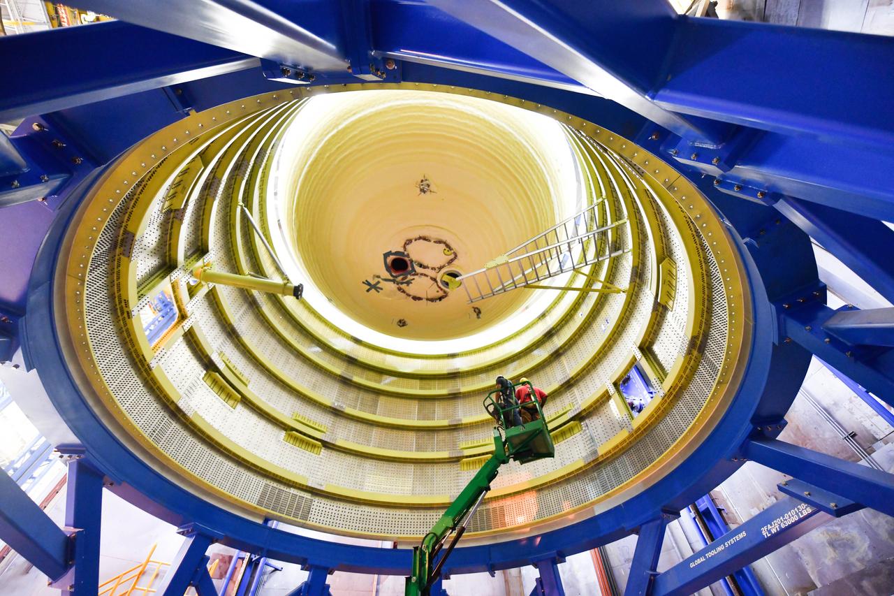
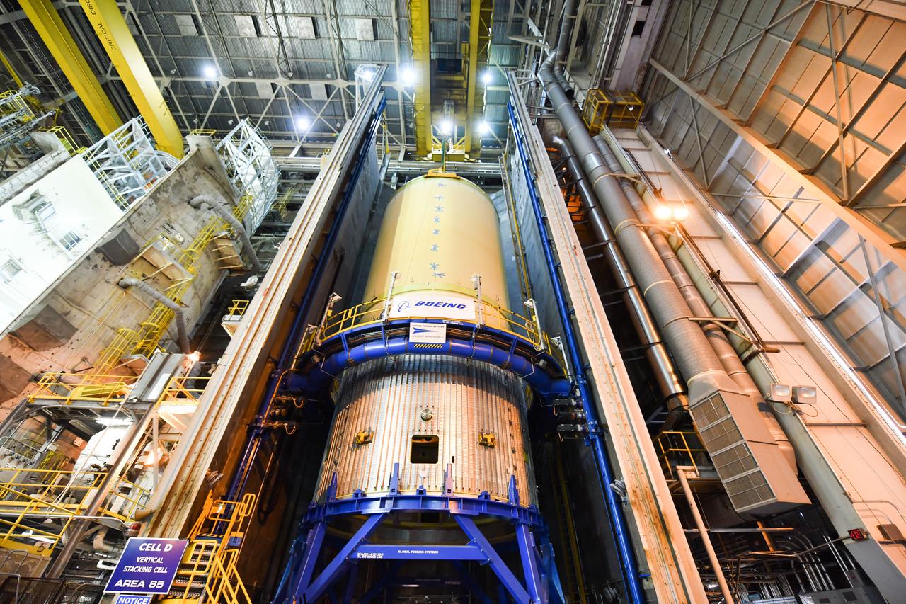
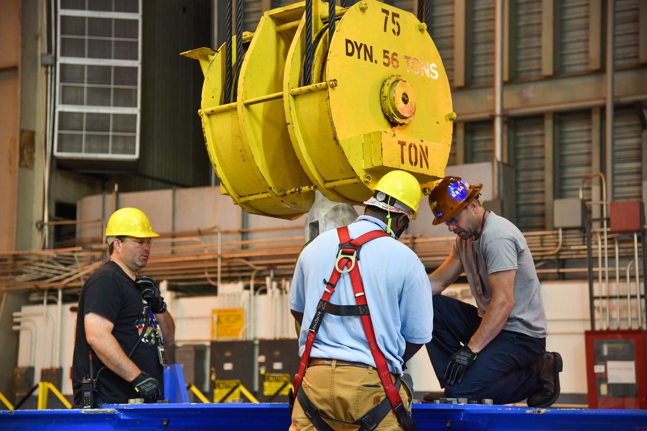
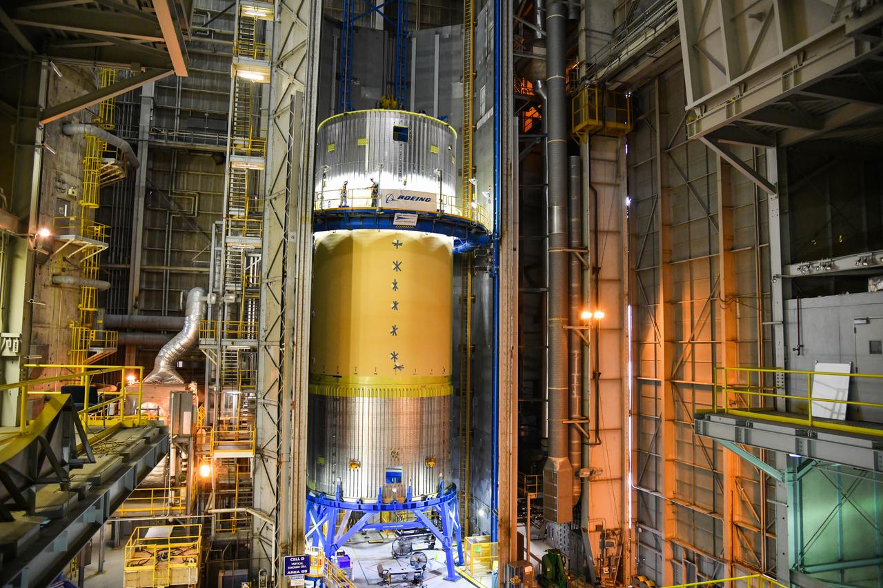
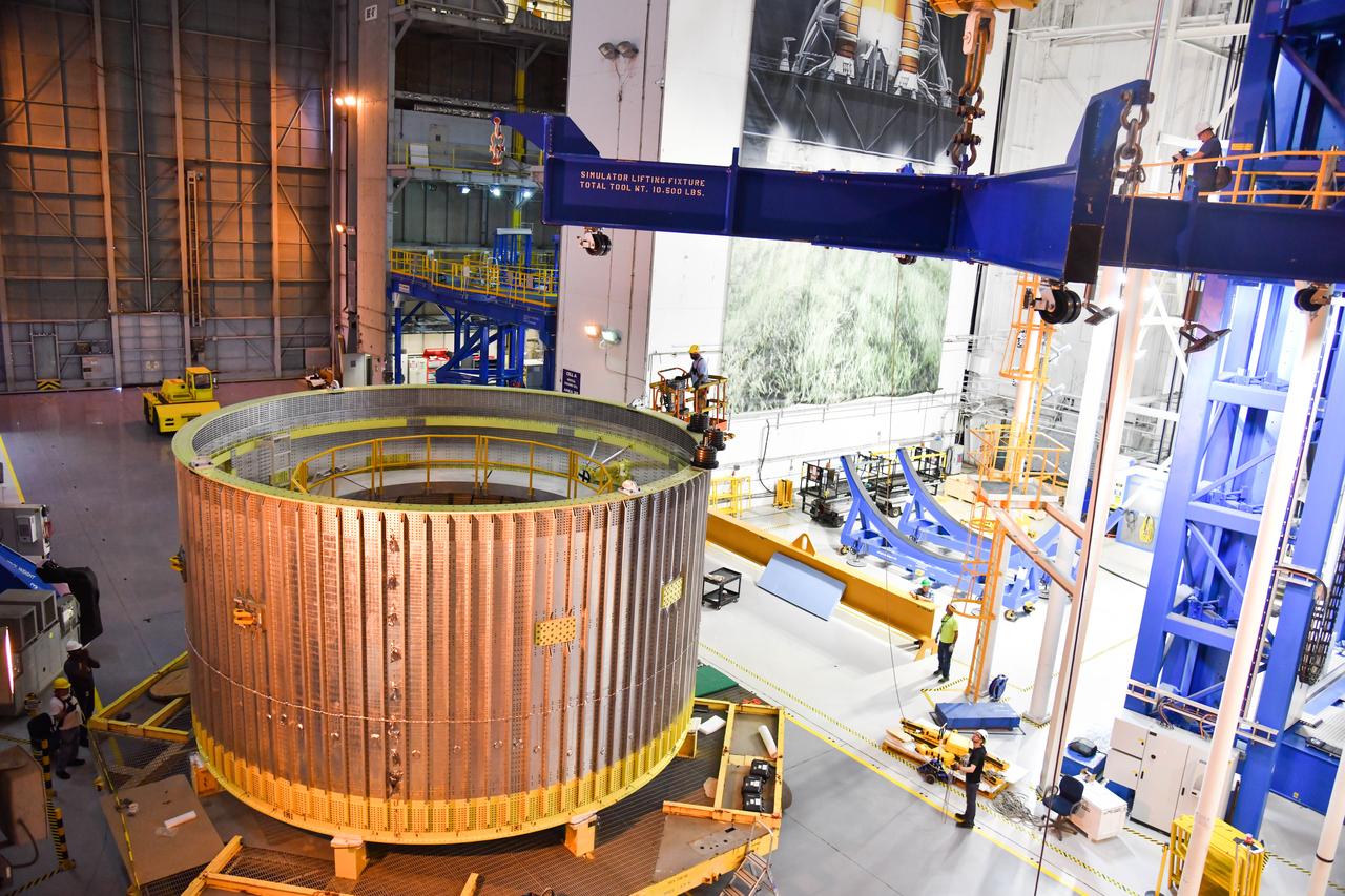
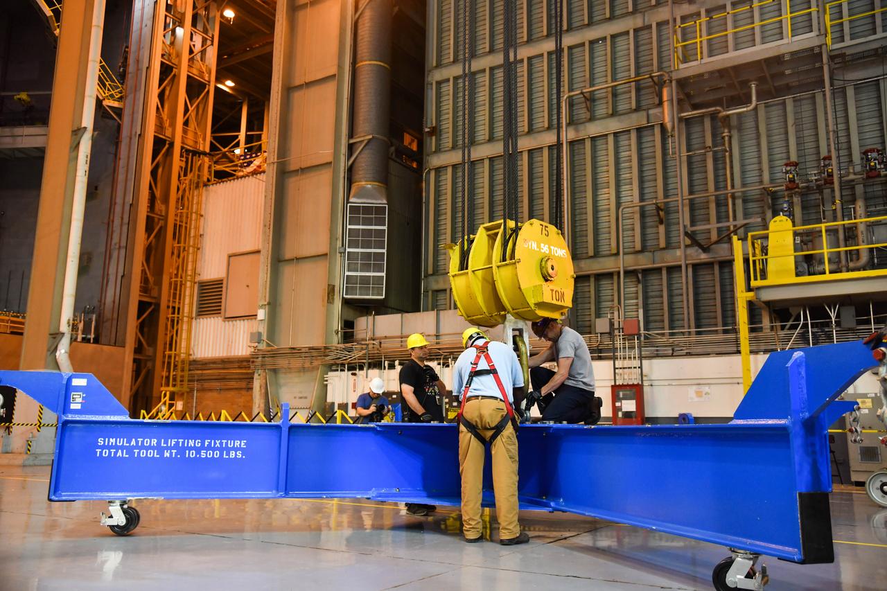
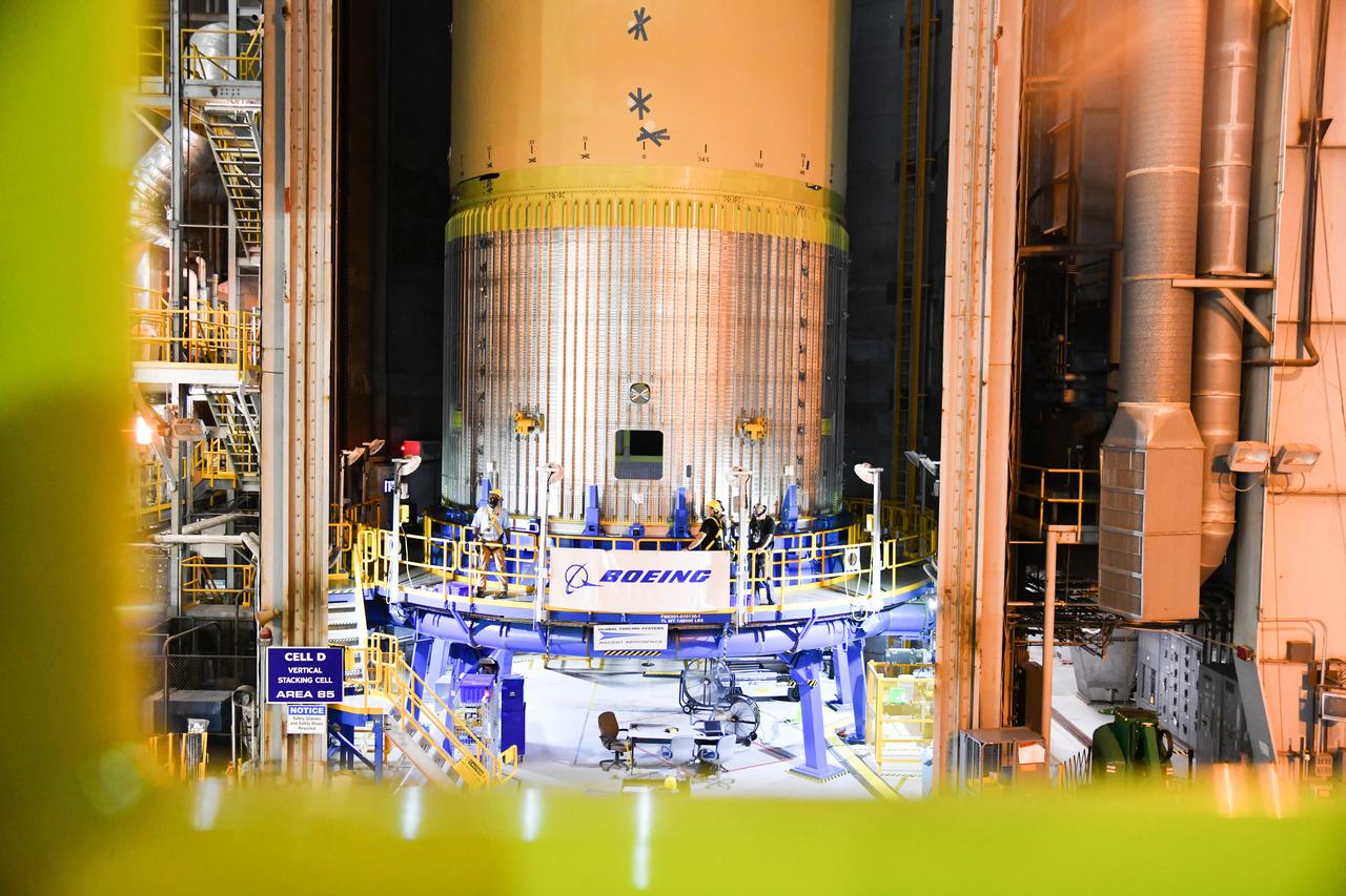
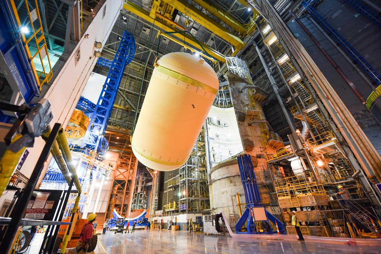
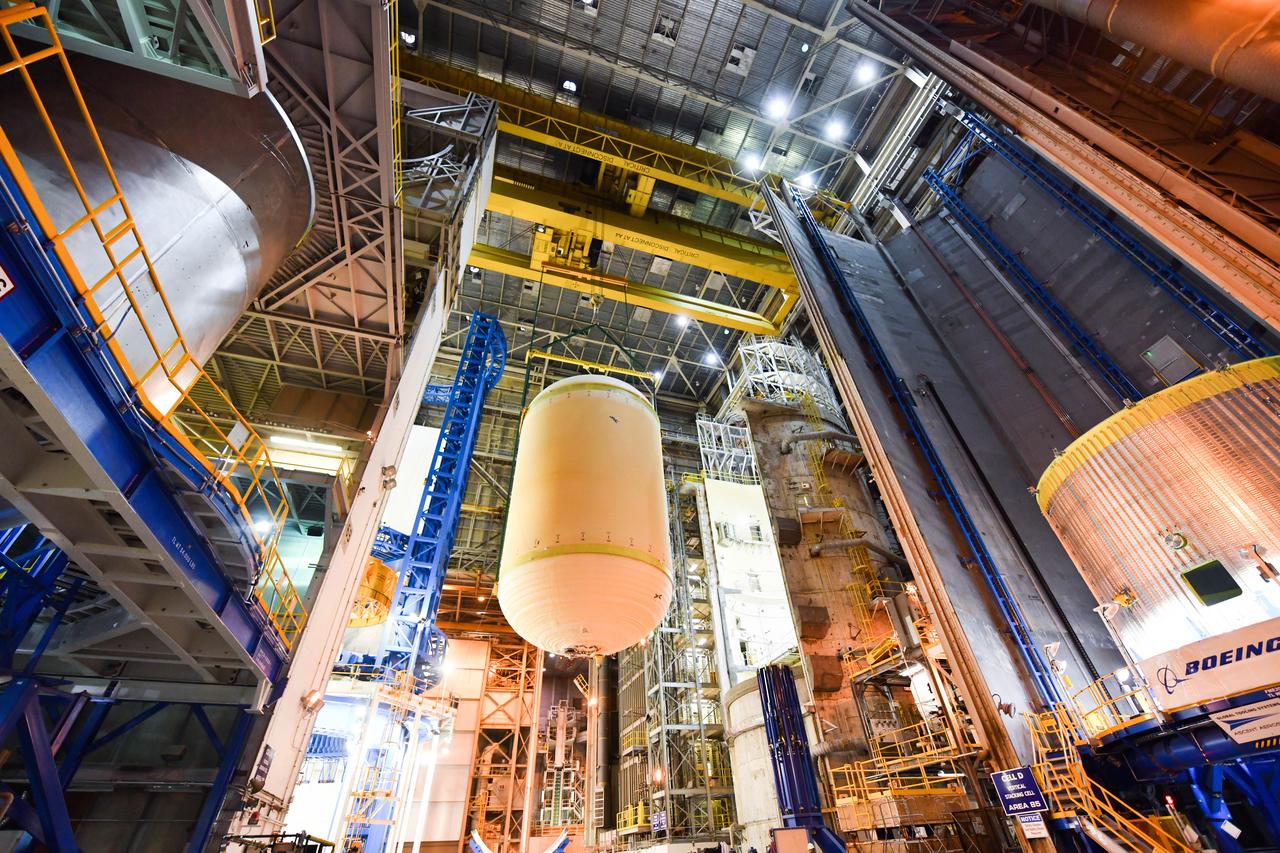
The Space Launch System (SLS) rocket’s liquid oxygen tank structural test article was manufactured and stacked in June 2019 at NASA’s Michoud Assembly Facility in New Orleans. To construct the test article, Boeing technicians at Michoud moved the liquid oxygen tank to the Vertical Assemby Building stacking and integration area. Here, they added simulators to mimic the two structures that connect to the tank, the intertank and the forward skirt. This structural hardware for the SLS core stage for America’s new deep space rocket is structurally identical to the flight version of the tank. It will be shipped on the Pegasus barge to NASA’s Marshall Space Flight Center in Hunstville, Alabama, where it will undergo a series of tests that simulate the stresses and loads of liftoff and flight. These tests will help ensure designs are adequate for successful SLS missions to the Moon and beyond. The flight liquid oxygen tank along with the liquid hydrogen tank supplies more than 500,000 gallons of propellant to the core stages four RS-25 engines, which produce 2 million pounds of thrust to help send the SLS rocket to space.
The Space Launch System (SLS) rocket’s liquid oxygen tank structural test article was manufactured and stacked in June 2019 at NASA’s Michoud Assembly Facility in New Orleans. To construct the test article, Boeing technicians at Michoud moved the liquid oxygen tank to the Vertical Assemby Building stacking and integration area. Here, they added simulators to mimic the two structures that connect to the tank, the intertank and the forward skirt. This structural hardware for the SLS core stage for America’s new deep space rocket is structurally identical to the flight version of the tank. It will be shipped on the Pegasus barge to NASA’s Marshall Space Flight Center in Hunstville, Alabama, where it will undergo a series of tests that simulate the stresses and loads of liftoff and flight. These tests will help ensure designs are adequate for successful SLS missions to the Moon and beyond. The flight liquid oxygen tank along with the liquid hydrogen tank supplies more than 500,000 gallons of propellant to the core stages four RS-25 engines, which produce 2 million pounds of thrust to help send the SLS rocket to space.
The Space Launch System (SLS) rocket’s liquid oxygen tank structural test article was manufactured and stacked in June 2019 at NASA’s Michoud Assembly Facility in New Orleans. To construct the test article, Boeing technicians at Michoud moved the liquid oxygen tank to the Vertical Assemby Building stacking and integration area. Here, they added simulators to mimic the two structures that connect to the tank, the intertank and the forward skirt. This structural hardware for the SLS core stage for America’s new deep space rocket is structurally identical to the flight version of the tank. It will be shipped on the Pegasus barge to NASA’s Marshall Space Flight Center in Hunstville, Alabama, where it will undergo a series of tests that simulate the stresses and loads of liftoff and flight. These tests will help ensure designs are adequate for successful SLS missions to the Moon and beyond. The flight liquid oxygen tank along with the liquid hydrogen tank supplies more than 500,000 gallons of propellant to the core stages four RS-25 engines, which produce 2 million pounds of thrust to help send the SLS rocket to space.
The Space Launch System (SLS) rocket’s liquid oxygen tank structural test article was manufactured and stacked in June 2019 at NASA’s Michoud Assembly Facility in New Orleans. To construct the test article, Boeing technicians at Michoud moved the liquid oxygen tank to the Vertical Assemby Building stacking and integration area. Here, they added simulators to mimic the two structures that connect to the tank, the intertank and the forward skirt. This structural hardware for the SLS core stage for America’s new deep space rocket is structurally identical to the flight version of the tank. It will be shipped on the Pegasus barge to NASA’s Marshall Space Flight Center in Hunstville, Alabama, where it will undergo a series of tests that simulate the stresses and loads of liftoff and flight. These tests will help ensure designs are adequate for successful SLS missions to the Moon and beyond. The flight liquid oxygen tank along with the liquid hydrogen tank supplies more than 500,000 gallons of propellant to the core stages four RS-25 engines, which produce 2 million pounds of thrust to help send the SLS rocket to space.
The Space Launch System (SLS) rocket’s liquid oxygen tank structural test article was manufactured and stacked in June 2019 at NASA’s Michoud Assembly Facility in New Orleans. To construct the test article, Boeing technicians at Michoud moved the liquid oxygen tank to the Vertical Assemby Building stacking and integration area. Here, they added simulators to mimic the two structures that connect to the tank, the intertank and the forward skirt. This structural hardware for the SLS core stage for America’s new deep space rocket is structurally identical to the flight version of the tank. It will be shipped on the Pegasus barge to NASA’s Marshall Space Flight Center in Hunstville, Alabama, where it will undergo a series of tests that simulate the stresses and loads of liftoff and flight. These tests will help ensure designs are adequate for successful SLS missions to the Moon and beyond. The flight liquid oxygen tank along with the liquid hydrogen tank supplies more than 500,000 gallons of propellant to the core stages four RS-25 engines, which produce 2 million pounds of thrust to help send the SLS rocket to space.
The Space Launch System (SLS) rocket’s liquid oxygen tank structural test article was manufactured and stacked in June 2019 at NASA’s Michoud Assembly Facility in New Orleans. To construct the test article, Boeing technicians at Michoud moved the liquid oxygen tank to the Vertical Assemby Building stacking and integration area. Here, they added simulators to mimic the two structures that connect to the tank, the intertank and the forward skirt. This structural hardware for the SLS core stage for America’s new deep space rocket is structurally identical to the flight version of the tank. It will be shipped on the Pegasus barge to NASA’s Marshall Space Flight Center in Hunstville, Alabama, where it will undergo a series of tests that simulate the stresses and loads of liftoff and flight. These tests will help ensure designs are adequate for successful SLS missions to the Moon and beyond. The flight liquid oxygen tank along with the liquid hydrogen tank supplies more than 500,000 gallons of propellant to the core stages four RS-25 engines, which produce 2 million pounds of thrust to help send the SLS rocket to space.
The Space Launch System (SLS) rocket’s liquid oxygen tank structural test article was manufactured and stacked in June 2019 at NASA’s Michoud Assembly Facility in New Orleans. To construct the test article, Boeing technicians at Michoud moved the liquid oxygen tank to the Vertical Assemby Building stacking and integration area. Here, they added simulators to mimic the two structures that connect to the tank, the intertank and the forward skirt. This structural hardware for the SLS core stage for America’s new deep space rocket is structurally identical to the flight version of the tank. It will be shipped on the Pegasus barge to NASA’s Marshall Space Flight Center in Hunstville, Alabama, where it will undergo a series of tests that simulate the stresses and loads of liftoff and flight. These tests will help ensure designs are adequate for successful SLS missions to the Moon and beyond. The flight liquid oxygen tank along with the liquid hydrogen tank supplies more than 500,000 gallons of propellant to the core stages four RS-25 engines, which produce 2 million pounds of thrust to help send the SLS rocket to space.
The Space Launch System (SLS) rocket’s liquid oxygen tank structural test article was manufactured and stacked in June 2019 at NASA’s Michoud Assembly Facility in New Orleans. To construct the test article, Boeing technicians at Michoud moved the liquid oxygen tank to the Vertical Assemby Building stacking and integration area. Here, they added simulators to mimic the two structures that connect to the tank, the intertank and the forward skirt. This structural hardware for the SLS core stage for America’s new deep space rocket is structurally identical to the flight version of the tank. It will be shipped on the Pegasus barge to NASA’s Marshall Space Flight Center in Hunstville, Alabama, where it will undergo a series of tests that simulate the stresses and loads of liftoff and flight. These tests will help ensure designs are adequate for successful SLS missions to the Moon and beyond. The flight liquid oxygen tank along with the liquid hydrogen tank supplies more than 500,000 gallons of propellant to the core stages four RS-25 engines, which produce 2 million pounds of thrust to help send the SLS rocket to space.
The Space Launch System (SLS) rocket’s liquid oxygen tank structural test article was manufactured and stacked in June 2019 at NASA’s Michoud Assembly Facility in New Orleans. To construct the test article, Boeing technicians at Michoud moved the liquid oxygen tank to the Vertical Assemby Building stacking and integration area. Here, they added simulators to mimic the two structures that connect to the tank, the intertank and the forward skirt. This structural hardware for the SLS core stage for America’s new deep space rocket is structurally identical to the flight version of the tank. It will be shipped on the Pegasus barge to NASA’s Marshall Space Flight Center in Hunstville, Alabama, where it will undergo a series of tests that simulate the stresses and loads of liftoff and flight. These tests will help ensure designs are adequate for successful SLS missions to the Moon and beyond. The flight liquid oxygen tank along with the liquid hydrogen tank supplies more than 500,000 gallons of propellant to the core stages four RS-25 engines, which produce 2 million pounds of thrust to help send the SLS rocket to space.
The Space Launch System (SLS) rocket’s liquid oxygen tank structural test article was manufactured and stacked in June 2019 at NASA’s Michoud Assembly Facility in New Orleans. To construct the test article, Boeing technicians at Michoud moved the liquid oxygen tank to the Vertical Assemby Building stacking and integration area. Here, they added simulators to mimic the two structures that connect to the tank, the intertank and the forward skirt. This structural hardware for the SLS core stage for America’s new deep space rocket is structurally identical to the flight version of the tank. It will be shipped on the Pegasus barge to NASA’s Marshall Space Flight Center in Hunstville, Alabama, where it will undergo a series of tests that simulate the stresses and loads of liftoff and flight. These tests will help ensure designs are adequate for successful SLS missions to the Moon and beyond. The flight liquid oxygen tank along with the liquid hydrogen tank supplies more than 500,000 gallons of propellant to the core stages four RS-25 engines, which produce 2 million pounds of thrust to help send the SLS rocket to space.
The Space Launch System (SLS) rocket’s liquid oxygen tank structural test article was manufactured and stacked in June 2019 at NASA’s Michoud Assembly Facility in New Orleans. To construct the test article, Boeing technicians at Michoud moved the liquid oxygen tank to the Vertical Assemby Building stacking and integration area. Here, they added simulators to mimic the two structures that connect to the tank, the intertank and the forward skirt. This structural hardware for the SLS core stage for America’s new deep space rocket is structurally identical to the flight version of the tank. It will be shipped on the Pegasus barge to NASA’s Marshall Space Flight Center in Hunstville, Alabama, where it will undergo a series of tests that simulate the stresses and loads of liftoff and flight. These tests will help ensure designs are adequate for successful SLS missions to the Moon and beyond. The flight liquid oxygen tank along with the liquid hydrogen tank supplies more than 500,000 gallons of propellant to the core stages four RS-25 engines, which produce 2 million pounds of thrust to help send the SLS rocket to space.
The Space Launch System (SLS) rocket’s liquid oxygen tank structural test article was manufactured and stacked in June 2019 at NASA’s Michoud Assembly Facility in New Orleans. To construct the test article, Boeing technicians at Michoud moved the liquid oxygen tank to the Vertical Assemby Building stacking and integration area. Here, they added simulators to mimic the two structures that connect to the tank, the intertank and the forward skirt. This structural hardware for the SLS core stage for America’s new deep space rocket is structurally identical to the flight version of the tank. It will be shipped on the Pegasus barge to NASA’s Marshall Space Flight Center in Hunstville, Alabama, where it will undergo a series of tests that simulate the stresses and loads of liftoff and flight. These tests will help ensure designs are adequate for successful SLS missions to the Moon and beyond. The flight liquid oxygen tank along with the liquid hydrogen tank supplies more than 500,000 gallons of propellant to the core stages four RS-25 engines, which produce 2 million pounds of thrust to help send the SLS rocket to space.
The Space Launch System (SLS) rocket’s liquid oxygen tank structural test article was manufactured and stacked in June 2019 at NASA’s Michoud Assembly Facility in New Orleans. To construct the test article, Boeing technicians at Michoud moved the liquid oxygen tank to the Vertical Assemby Building stacking and integration area. Here, they added simulators to mimic the two structures that connect to the tank, the intertank and the forward skirt. This structural hardware for the SLS core stage for America’s new deep space rocket is structurally identical to the flight version of the tank. It will be shipped on the Pegasus barge to NASA’s Marshall Space Flight Center in Hunstville, Alabama, where it will undergo a series of tests that simulate the stresses and loads of liftoff and flight. These tests will help ensure designs are adequate for successful SLS missions to the Moon and beyond. The flight liquid oxygen tank along with the liquid hydrogen tank supplies more than 500,000 gallons of propellant to the core stages four RS-25 engines, which produce 2 million pounds of thrust to help send the SLS rocket to space.
The Space Launch System (SLS) rocket’s liquid oxygen tank structural test article was manufactured and stacked in June 2019 at NASA’s Michoud Assembly Facility in New Orleans. To construct the test article, Boeing technicians at Michoud moved the liquid oxygen tank to the Vertical Assemby Building stacking and integration area. Here, they added simulators to mimic the two structures that connect to the tank, the intertank and the forward skirt. This structural hardware for the SLS core stage for America’s new deep space rocket is structurally identical to the flight version of the tank. It will be shipped on the Pegasus barge to NASA’s Marshall Space Flight Center in Hunstville, Alabama, where it will undergo a series of tests that simulate the stresses and loads of liftoff and flight. These tests will help ensure designs are adequate for successful SLS missions to the Moon and beyond. The flight liquid oxygen tank along with the liquid hydrogen tank supplies more than 500,000 gallons of propellant to the core stages four RS-25 engines, which produce 2 million pounds of thrust to help send the SLS rocket to space.
The Space Launch System (SLS) rocket’s liquid oxygen tank structural test article was manufactured and stacked in June 2019 at NASA’s Michoud Assembly Facility in New Orleans. To construct the test article, Boeing technicians at Michoud moved the liquid oxygen tank to the Vertical Assemby Building stacking and integration area. Here, they added simulators to mimic the two structures that connect to the tank, the intertank and the forward skirt. This structural hardware for the SLS core stage for America’s new deep space rocket is structurally identical to the flight version of the tank. It will be shipped on the Pegasus barge to NASA’s Marshall Space Flight Center in Hunstville, Alabama, where it will undergo a series of tests that simulate the stresses and loads of liftoff and flight. These tests will help ensure designs are adequate for successful SLS missions to the Moon and beyond. The flight liquid oxygen tank along with the liquid hydrogen tank supplies more than 500,000 gallons of propellant to the core stages four RS-25 engines, which produce 2 million pounds of thrust to help send the SLS rocket to space.
The Space Launch System (SLS) rocket’s liquid oxygen tank structural test article was manufactured and stacked in June 2019 at NASA’s Michoud Assembly Facility in New Orleans. To construct the test article, Boeing technicians at Michoud moved the liquid oxygen tank to the Vertical Assemby Building stacking and integration area. Here, they added simulators to mimic the two structures that connect to the tank, the intertank and the forward skirt. This structural hardware for the SLS core stage for America’s new deep space rocket is structurally identical to the flight version of the tank. It will be shipped on the Pegasus barge to NASA’s Marshall Space Flight Center in Hunstville, Alabama, where it will undergo a series of tests that simulate the stresses and loads of liftoff and flight. These tests will help ensure designs are adequate for successful SLS missions to the Moon and beyond. The flight liquid oxygen tank along with the liquid hydrogen tank supplies more than 500,000 gallons of propellant to the core stages four RS-25 engines, which produce 2 million pounds of thrust to help send the SLS rocket to space.
The Space Launch System (SLS) rocket’s liquid oxygen tank structural test article was manufactured and stacked in June 2019 at NASA’s Michoud Assembly Facility in New Orleans. To construct the test article, Boeing technicians at Michoud moved the liquid oxygen tank to the Vertical Assemby Building stacking and integration area. Here, they added simulators to mimic the two structures that connect to the tank, the intertank and the forward skirt. This structural hardware for the SLS core stage for America’s new deep space rocket is structurally identical to the flight version of the tank. It will be shipped on the Pegasus barge to NASA’s Marshall Space Flight Center in Hunstville, Alabama, where it will undergo a series of tests that simulate the stresses and loads of liftoff and flight. These tests will help ensure designs are adequate for successful SLS missions to the Moon and beyond. The flight liquid oxygen tank along with the liquid hydrogen tank supplies more than 500,000 gallons of propellant to the core stages four RS-25 engines, which produce 2 million pounds of thrust to help send the SLS rocket to space.
The Space Launch System (SLS) rocket’s liquid oxygen tank structural test article was manufactured and stacked in June 2019 at NASA’s Michoud Assembly Facility in New Orleans. To construct the test article, Boeing technicians at Michoud moved the liquid oxygen tank to the Vertical Assemby Building stacking and integration area. Here, they added simulators to mimic the two structures that connect to the tank, the intertank and the forward skirt. This structural hardware for the SLS core stage for America’s new deep space rocket is structurally identical to the flight version of the tank. It will be shipped on the Pegasus barge to NASA’s Marshall Space Flight Center in Hunstville, Alabama, where it will undergo a series of tests that simulate the stresses and loads of liftoff and flight. These tests will help ensure designs are adequate for successful SLS missions to the Moon and beyond. The flight liquid oxygen tank along with the liquid hydrogen tank supplies more than 500,000 gallons of propellant to the core stages four RS-25 engines, which produce 2 million pounds of thrust to help send the SLS rocket to space.
The Space Launch System (SLS) rocket’s liquid oxygen tank structural test article was manufactured and stacked in June 2019 at NASA’s Michoud Assembly Facility in New Orleans. To construct the test article, Boeing technicians at Michoud moved the liquid oxygen tank to the Vertical Assemby Building stacking and integration area. Here, they added simulators to mimic the two structures that connect to the tank, the intertank and the forward skirt. This structural hardware for the SLS core stage for America’s new deep space rocket is structurally identical to the flight version of the tank. It will be shipped on the Pegasus barge to NASA’s Marshall Space Flight Center in Hunstville, Alabama, where it will undergo a series of tests that simulate the stresses and loads of liftoff and flight. These tests will help ensure designs are adequate for successful SLS missions to the Moon and beyond. The flight liquid oxygen tank along with the liquid hydrogen tank supplies more than 500,000 gallons of propellant to the core stages four RS-25 engines, which produce 2 million pounds of thrust to help send the SLS rocket to space.
The Space Launch System (SLS) rocket’s liquid oxygen tank structural test article was manufactured and stacked in June 2019 at NASA’s Michoud Assembly Facility in New Orleans. To construct the test article, Boeing technicians at Michoud moved the liquid oxygen tank to the Vertical Assemby Building stacking and integration area. Here, they added simulators to mimic the two structures that connect to the tank, the intertank and the forward skirt. This structural hardware for the SLS core stage for America’s new deep space rocket is structurally identical to the flight version of the tank. It will be shipped on the Pegasus barge to NASA’s Marshall Space Flight Center in Hunstville, Alabama, where it will undergo a series of tests that simulate the stresses and loads of liftoff and flight. These tests will help ensure designs are adequate for successful SLS missions to the Moon and beyond. The flight liquid oxygen tank along with the liquid hydrogen tank supplies more than 500,000 gallons of propellant to the core stages four RS-25 engines, which produce 2 million pounds of thrust to help send the SLS rocket to space.
The Space Launch System (SLS) rocket’s liquid oxygen tank structural test article was manufactured and stacked in June 2019 at NASA’s Michoud Assembly Facility in New Orleans. To construct the test article, Boeing technicians at Michoud moved the liquid oxygen tank to the Vertical Assemby Building stacking and integration area. Here, they added simulators to mimic the two structures that connect to the tank, the intertank and the forward skirt. This structural hardware for the SLS core stage for America’s new deep space rocket is structurally identical to the flight version of the tank. It will be shipped on the Pegasus barge to NASA’s Marshall Space Flight Center in Hunstville, Alabama, where it will undergo a series of tests that simulate the stresses and loads of liftoff and flight. These tests will help ensure designs are adequate for successful SLS missions to the Moon and beyond. The flight liquid oxygen tank along with the liquid hydrogen tank supplies more than 500,000 gallons of propellant to the core stages four RS-25 engines, which produce 2 million pounds of thrust to help send the SLS rocket to space.
The Space Launch System (SLS) rocket’s liquid oxygen tank structural test article was manufactured and stacked in June 2019 at NASA’s Michoud Assembly Facility in New Orleans. To construct the test article, Boeing technicians at Michoud moved the liquid oxygen tank to the Vertical Assemby Building stacking and integration area. Here, they added simulators to mimic the two structures that connect to the tank, the intertank and the forward skirt. This structural hardware for the SLS core stage for America’s new deep space rocket is structurally identical to the flight version of the tank. It will be shipped on the Pegasus barge to NASA’s Marshall Space Flight Center in Hunstville, Alabama, where it will undergo a series of tests that simulate the stresses and loads of liftoff and flight. These tests will help ensure designs are adequate for successful SLS missions to the Moon and beyond. The flight liquid oxygen tank along with the liquid hydrogen tank supplies more than 500,000 gallons of propellant to the core stages four RS-25 engines, which produce 2 million pounds of thrust to help send the SLS rocket to space.
The Space Launch System (SLS) rocket’s liquid oxygen tank structural test article was manufactured and stacked in June 2019 at NASA’s Michoud Assembly Facility in New Orleans. To construct the test article, Boeing technicians at Michoud moved the liquid oxygen tank to the Vertical Assemby Building stacking and integration area. Here, they added simulators to mimic the two structures that connect to the tank, the intertank and the forward skirt. This structural hardware for the SLS core stage for America’s new deep space rocket is structurally identical to the flight version of the tank. It will be shipped on the Pegasus barge to NASA’s Marshall Space Flight Center in Hunstville, Alabama, where it will undergo a series of tests that simulate the stresses and loads of liftoff and flight. These tests will help ensure designs are adequate for successful SLS missions to the Moon and beyond. The flight liquid oxygen tank along with the liquid hydrogen tank supplies more than 500,000 gallons of propellant to the core stages four RS-25 engines, which produce 2 million pounds of thrust to help send the SLS rocket to space.
The Space Launch System (SLS) rocket’s liquid oxygen tank structural test article was manufactured and stacked in June 2019 at NASA’s Michoud Assembly Facility in New Orleans. To construct the test article, Boeing technicians at Michoud moved the liquid oxygen tank to the Vertical Assemby Building stacking and integration area. Here, they added simulators to mimic the two structures that connect to the tank, the intertank and the forward skirt. This structural hardware for the SLS core stage for America’s new deep space rocket is structurally identical to the flight version of the tank. It will be shipped on the Pegasus barge to NASA’s Marshall Space Flight Center in Hunstville, Alabama, where it will undergo a series of tests that simulate the stresses and loads of liftoff and flight. These tests will help ensure designs are adequate for successful SLS missions to the Moon and beyond. The flight liquid oxygen tank along with the liquid hydrogen tank supplies more than 500,000 gallons of propellant to the core stages four RS-25 engines, which produce 2 million pounds of thrust to help send the SLS rocket to space.
The Space Launch System (SLS) rocket’s liquid oxygen tank structural test article was manufactured and stacked in June 2019 at NASA’s Michoud Assembly Facility in New Orleans. To construct the test article, Boeing technicians at Michoud moved the liquid oxygen tank to the Vertical Assemby Building stacking and integration area. Here, they added simulators to mimic the two structures that connect to the tank, the intertank and the forward skirt. This structural hardware for the SLS core stage for America’s new deep space rocket is structurally identical to the flight version of the tank. It will be shipped on the Pegasus barge to NASA’s Marshall Space Flight Center in Hunstville, Alabama, where it will undergo a series of tests that simulate the stresses and loads of liftoff and flight. These tests will help ensure designs are adequate for successful SLS missions to the Moon and beyond. The flight liquid oxygen tank along with the liquid hydrogen tank supplies more than 500,000 gallons of propellant to the core stages four RS-25 engines, which produce 2 million pounds of thrust to help send the SLS rocket to space.
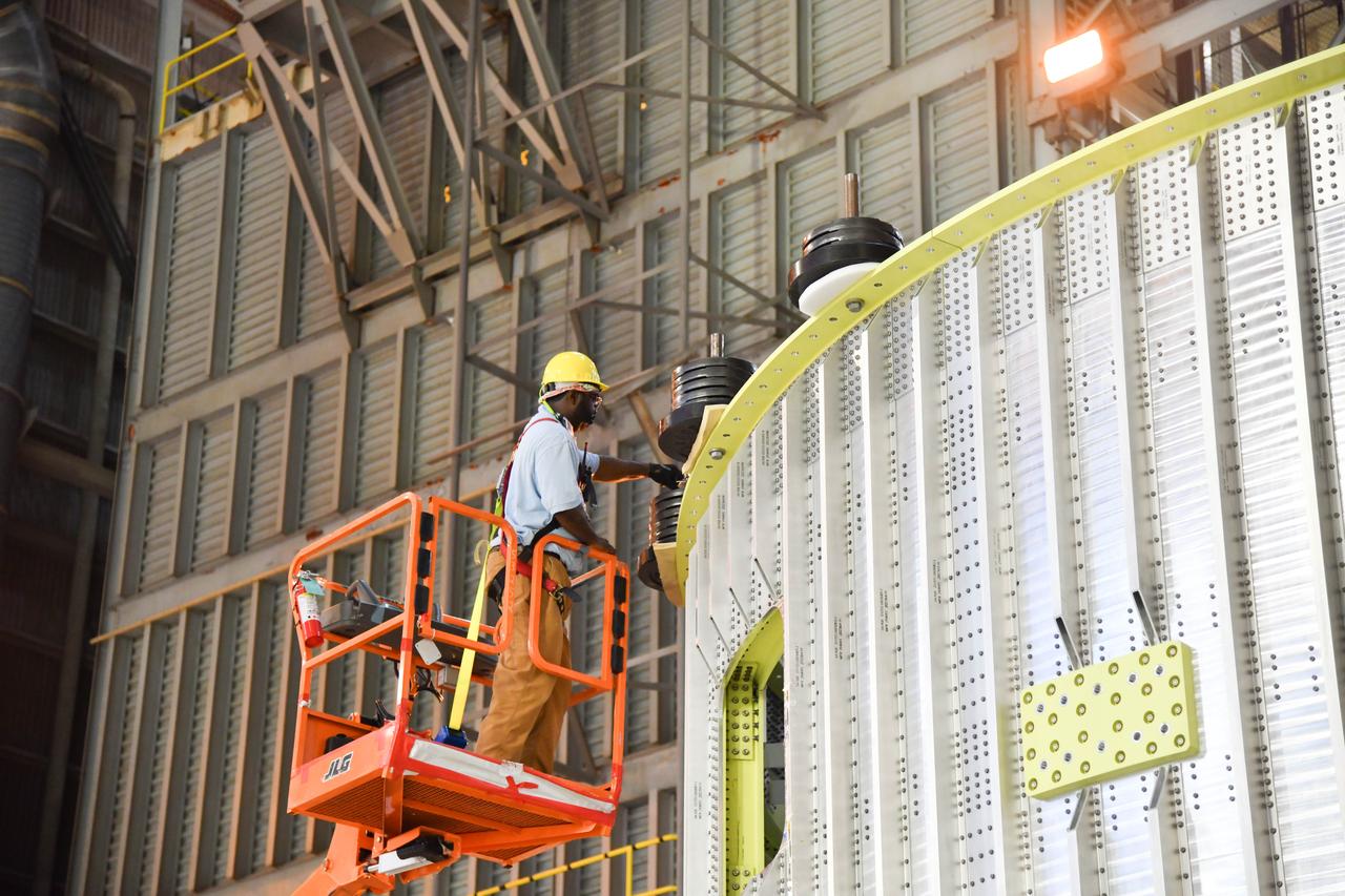
The Space Launch System (SLS) rocket’s liquid oxygen tank structural test article was manufactured and stacked in June 2019 at NASA’s Michoud Assembly Facility in New Orleans. To construct the test article, Boeing technicians at Michoud moved the liquid oxygen tank to the Vertical Assemby Building stacking and integration area. Here, they added simulators to mimic the two structures that connect to the tank, the intertank and the forward skirt. This structural hardware for the SLS core stage for America’s new deep space rocket is structurally identical to the flight version of the tank. It will be shipped on the Pegasus barge to NASA’s Marshall Space Flight Center in Hunstville, Alabama, where it will undergo a series of tests that simulate the stresses and loads of liftoff and flight. These tests will help ensure designs are adequate for successful SLS missions to the Moon and beyond. The flight liquid oxygen tank along with the liquid hydrogen tank supplies more than 500,000 gallons of propellant to the core stages four RS-25 engines, which produce 2 million pounds of thrust to help send the SLS rocket to space.
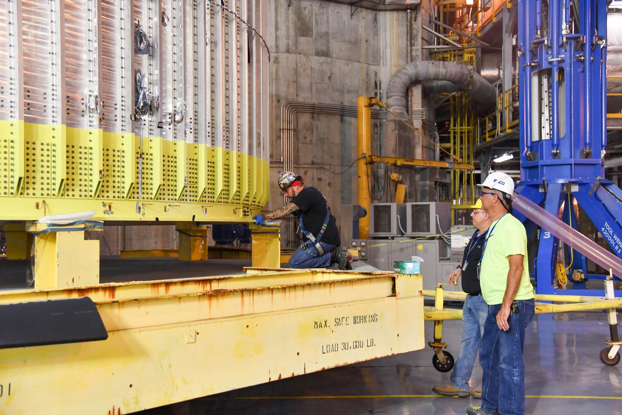
The Space Launch System (SLS) rocket’s liquid oxygen tank structural test article was manufactured and stacked in June 2019 at NASA’s Michoud Assembly Facility in New Orleans. To construct the test article, Boeing technicians at Michoud moved the liquid oxygen tank to the Vertical Assemby Building stacking and integration area. Here, they added simulators to mimic the two structures that connect to the tank, the intertank and the forward skirt. This structural hardware for the SLS core stage for America’s new deep space rocket is structurally identical to the flight version of the tank. It will be shipped on the Pegasus barge to NASA’s Marshall Space Flight Center in Hunstville, Alabama, where it will undergo a series of tests that simulate the stresses and loads of liftoff and flight. These tests will help ensure designs are adequate for successful SLS missions to the Moon and beyond. The flight liquid oxygen tank along with the liquid hydrogen tank supplies more than 500,000 gallons of propellant to the core stages four RS-25 engines, which produce 2 million pounds of thrust to help send the SLS rocket to space.
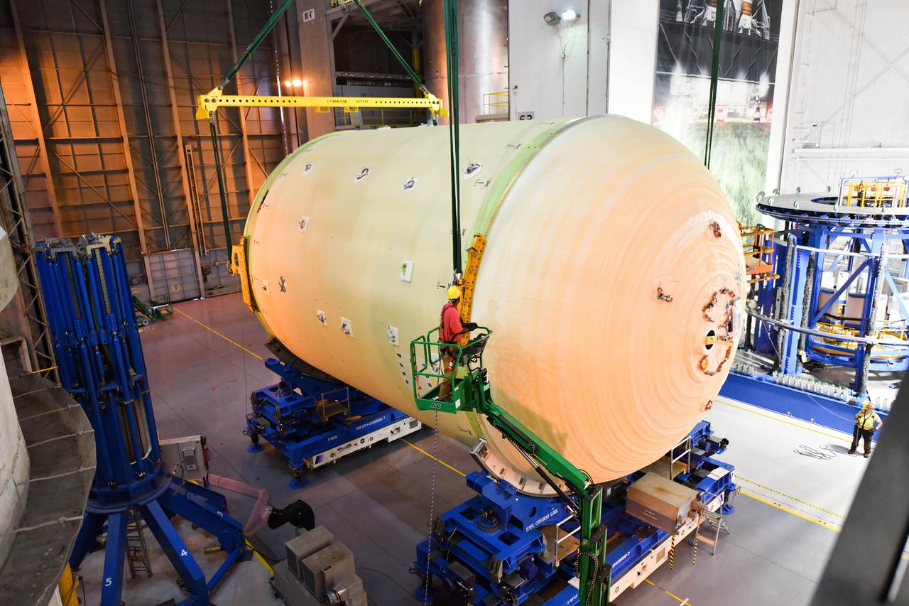
The Space Launch System (SLS) rocket’s liquid oxygen tank structural test article was manufactured and stacked in June 2019 at NASA’s Michoud Assembly Facility in New Orleans. To construct the test article, Boeing technicians at Michoud moved the liquid oxygen tank to the Vertical Assemby Building stacking and integration area. Here, they added simulators to mimic the two structures that connect to the tank, the intertank and the forward skirt. This structural hardware for the SLS core stage for America’s new deep space rocket is structurally identical to the flight version of the tank. It will be shipped on the Pegasus barge to NASA’s Marshall Space Flight Center in Hunstville, Alabama, where it will undergo a series of tests that simulate the stresses and loads of liftoff and flight. These tests will help ensure designs are adequate for successful SLS missions to the Moon and beyond. The flight liquid oxygen tank along with the liquid hydrogen tank supplies more than 500,000 gallons of propellant to the core stages four RS-25 engines, which produce 2 million pounds of thrust to help send the SLS rocket to space.
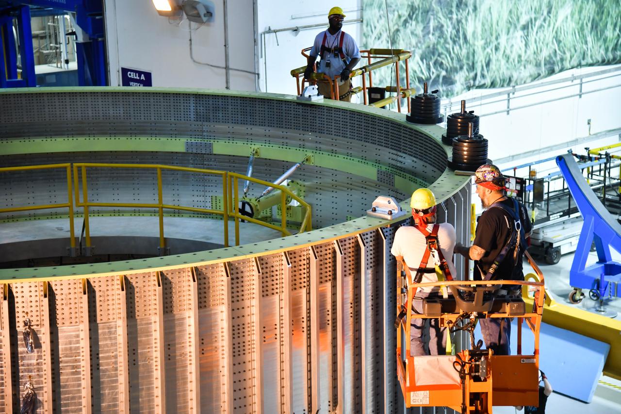
The Space Launch System (SLS) rocket’s liquid oxygen tank structural test article was manufactured and stacked in June 2019 at NASA’s Michoud Assembly Facility in New Orleans. To construct the test article, Boeing technicians at Michoud moved the liquid oxygen tank to the Vertical Assemby Building stacking and integration area. Here, they added simulators to mimic the two structures that connect to the tank, the intertank and the forward skirt. This structural hardware for the SLS core stage for America’s new deep space rocket is structurally identical to the flight version of the tank. It will be shipped on the Pegasus barge to NASA’s Marshall Space Flight Center in Hunstville, Alabama, where it will undergo a series of tests that simulate the stresses and loads of liftoff and flight. These tests will help ensure designs are adequate for successful SLS missions to the Moon and beyond. The flight liquid oxygen tank along with the liquid hydrogen tank supplies more than 500,000 gallons of propellant to the core stages four RS-25 engines, which produce 2 million pounds of thrust to help send the SLS rocket to space.
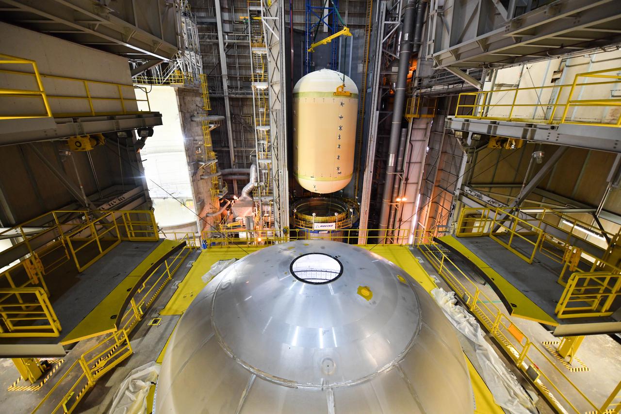
The Space Launch System (SLS) rocket’s liquid oxygen tank structural test article was manufactured and stacked in June 2019 at NASA’s Michoud Assembly Facility in New Orleans. To construct the test article, Boeing technicians at Michoud moved the liquid oxygen tank to the Vertical Assemby Building stacking and integration area. Here, they added simulators to mimic the two structures that connect to the tank, the intertank and the forward skirt. This structural hardware for the SLS core stage for America’s new deep space rocket is structurally identical to the flight version of the tank. It will be shipped on the Pegasus barge to NASA’s Marshall Space Flight Center in Hunstville, Alabama, where it will undergo a series of tests that simulate the stresses and loads of liftoff and flight. These tests will help ensure designs are adequate for successful SLS missions to the Moon and beyond. The flight liquid oxygen tank along with the liquid hydrogen tank supplies more than 500,000 gallons of propellant to the core stages four RS-25 engines, which produce 2 million pounds of thrust to help send the SLS rocket to space.
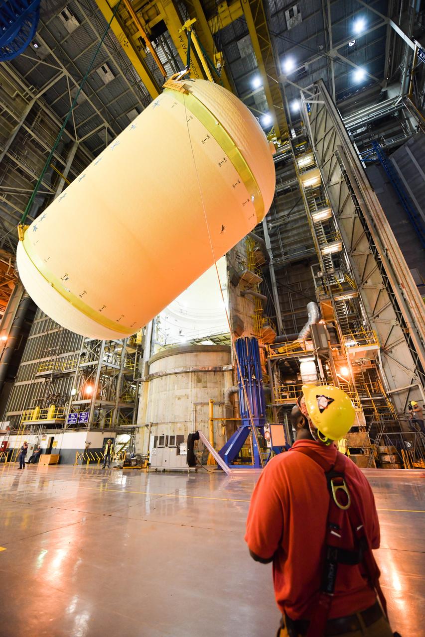
The Space Launch System (SLS) rocket’s liquid oxygen tank structural test article was manufactured and stacked in June 2019 at NASA’s Michoud Assembly Facility in New Orleans. To construct the test article, Boeing technicians at Michoud moved the liquid oxygen tank to the Vertical Assemby Building stacking and integration area. Here, they added simulators to mimic the two structures that connect to the tank, the intertank and the forward skirt. This structural hardware for the SLS core stage for America’s new deep space rocket is structurally identical to the flight version of the tank. It will be shipped on the Pegasus barge to NASA’s Marshall Space Flight Center in Hunstville, Alabama, where it will undergo a series of tests that simulate the stresses and loads of liftoff and flight. These tests will help ensure designs are adequate for successful SLS missions to the Moon and beyond. The flight liquid oxygen tank along with the liquid hydrogen tank supplies more than 500,000 gallons of propellant to the core stages four RS-25 engines, which produce 2 million pounds of thrust to help send the SLS rocket to space.
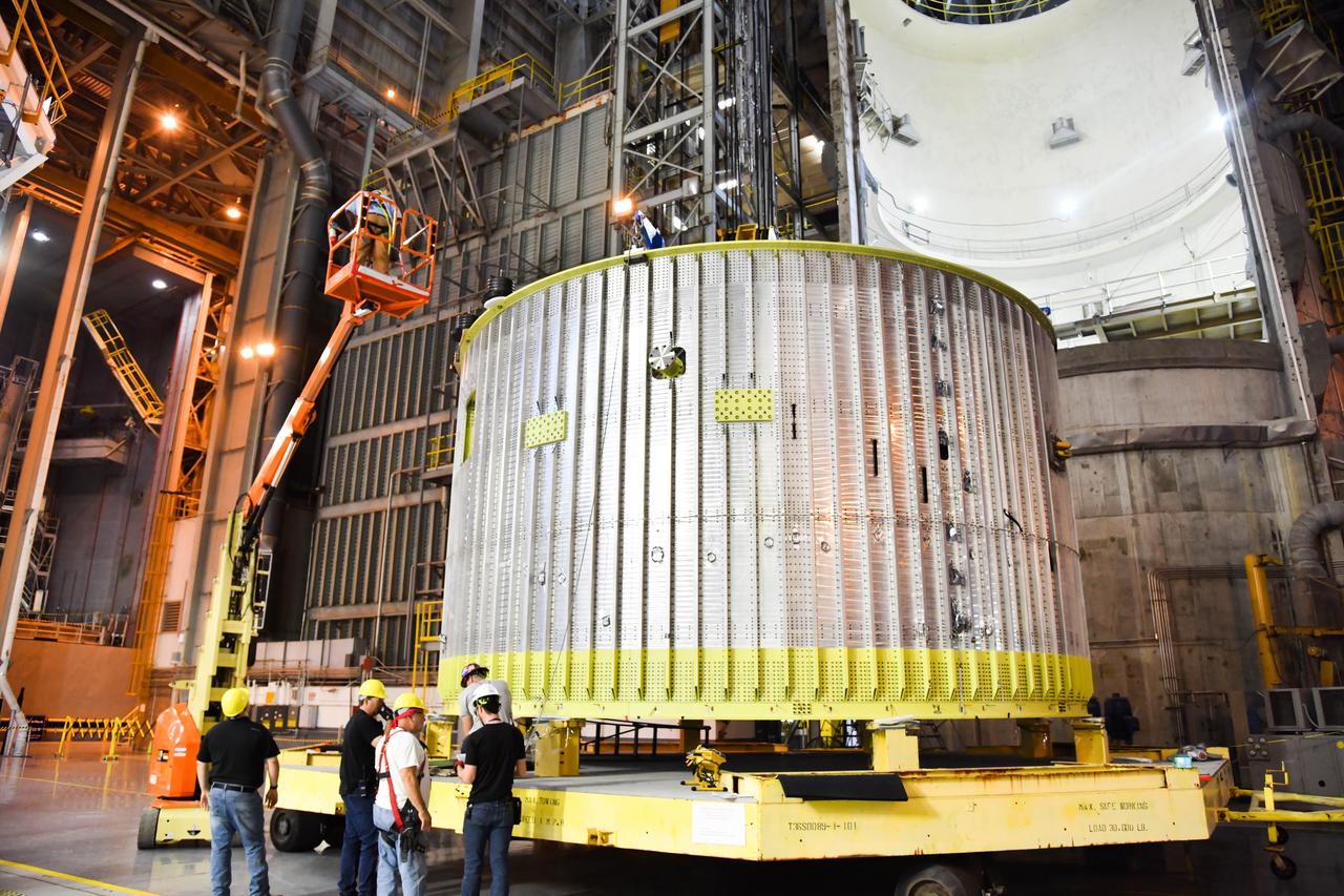
The Space Launch System (SLS) rocket’s liquid oxygen tank structural test article was manufactured and stacked in June 2019 at NASA’s Michoud Assembly Facility in New Orleans. To construct the test article, Boeing technicians at Michoud moved the liquid oxygen tank to the Vertical Assemby Building stacking and integration area. Here, they added simulators to mimic the two structures that connect to the tank, the intertank and the forward skirt. This structural hardware for the SLS core stage for America’s new deep space rocket is structurally identical to the flight version of the tank. It will be shipped on the Pegasus barge to NASA’s Marshall Space Flight Center in Hunstville, Alabama, where it will undergo a series of tests that simulate the stresses and loads of liftoff and flight. These tests will help ensure designs are adequate for successful SLS missions to the Moon and beyond. The flight liquid oxygen tank along with the liquid hydrogen tank supplies more than 500,000 gallons of propellant to the core stages four RS-25 engines, which produce 2 million pounds of thrust to help send the SLS rocket to space.
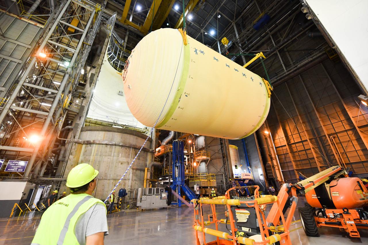
The Space Launch System (SLS) rocket’s liquid oxygen tank structural test article was manufactured and stacked in June 2019 at NASA’s Michoud Assembly Facility in New Orleans. To construct the test article, Boeing technicians at Michoud moved the liquid oxygen tank to the Vertical Assemby Building stacking and integration area. Here, they added simulators to mimic the two structures that connect to the tank, the intertank and the forward skirt. This structural hardware for the SLS core stage for America’s new deep space rocket is structurally identical to the flight version of the tank. It will be shipped on the Pegasus barge to NASA’s Marshall Space Flight Center in Hunstville, Alabama, where it will undergo a series of tests that simulate the stresses and loads of liftoff and flight. These tests will help ensure designs are adequate for successful SLS missions to the Moon and beyond. The flight liquid oxygen tank along with the liquid hydrogen tank supplies more than 500,000 gallons of propellant to the core stages four RS-25 engines, which produce 2 million pounds of thrust to help send the SLS rocket to space.
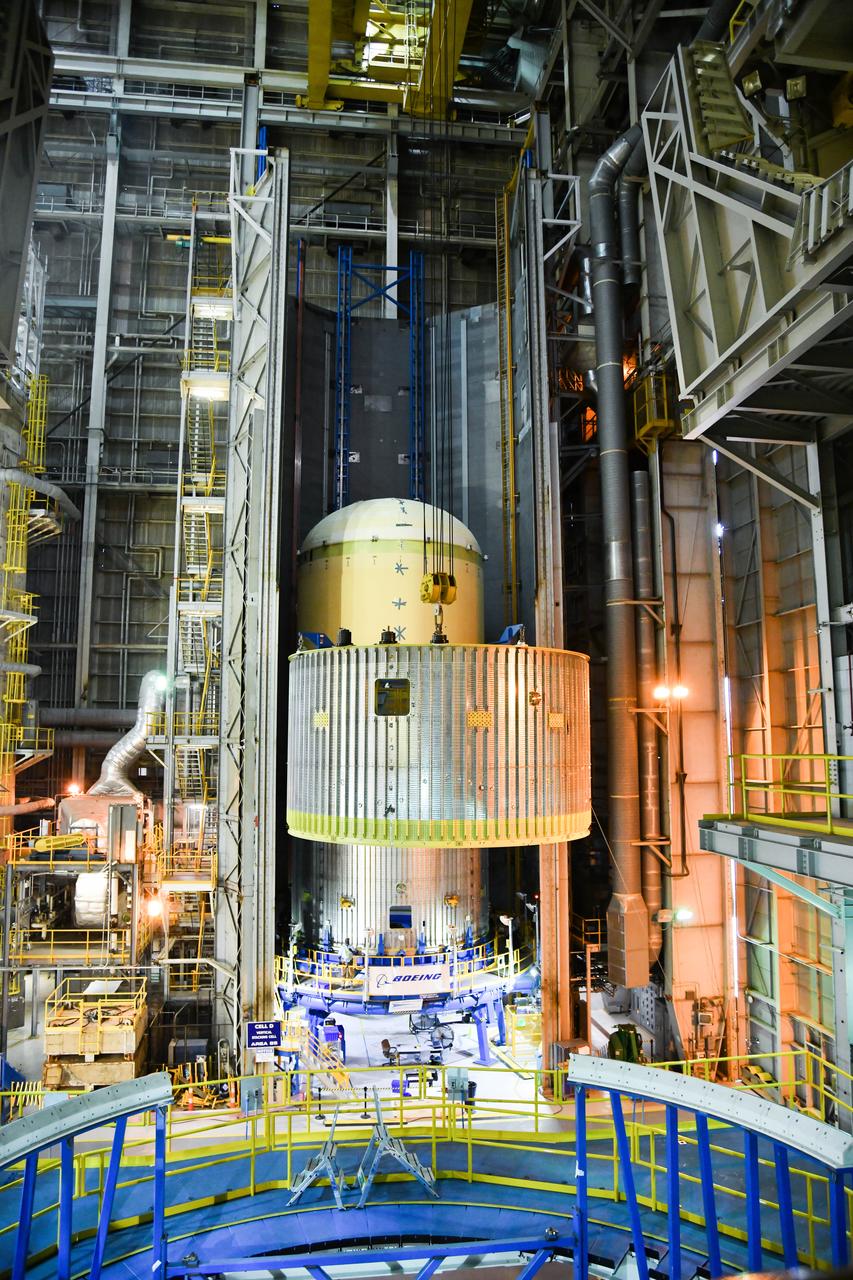
The Space Launch System (SLS) rocket’s liquid oxygen tank structural test article was manufactured and stacked in June 2019 at NASA’s Michoud Assembly Facility in New Orleans. To construct the test article, Boeing technicians at Michoud moved the liquid oxygen tank to the Vertical Assemby Building stacking and integration area. Here, they added simulators to mimic the two structures that connect to the tank, the intertank and the forward skirt. This structural hardware for the SLS core stage for America’s new deep space rocket is structurally identical to the flight version of the tank. It will be shipped on the Pegasus barge to NASA’s Marshall Space Flight Center in Hunstville, Alabama, where it will undergo a series of tests that simulate the stresses and loads of liftoff and flight. These tests will help ensure designs are adequate for successful SLS missions to the Moon and beyond. The flight liquid oxygen tank along with the liquid hydrogen tank supplies more than 500,000 gallons of propellant to the core stages four RS-25 engines, which produce 2 million pounds of thrust to help send the SLS rocket to space.
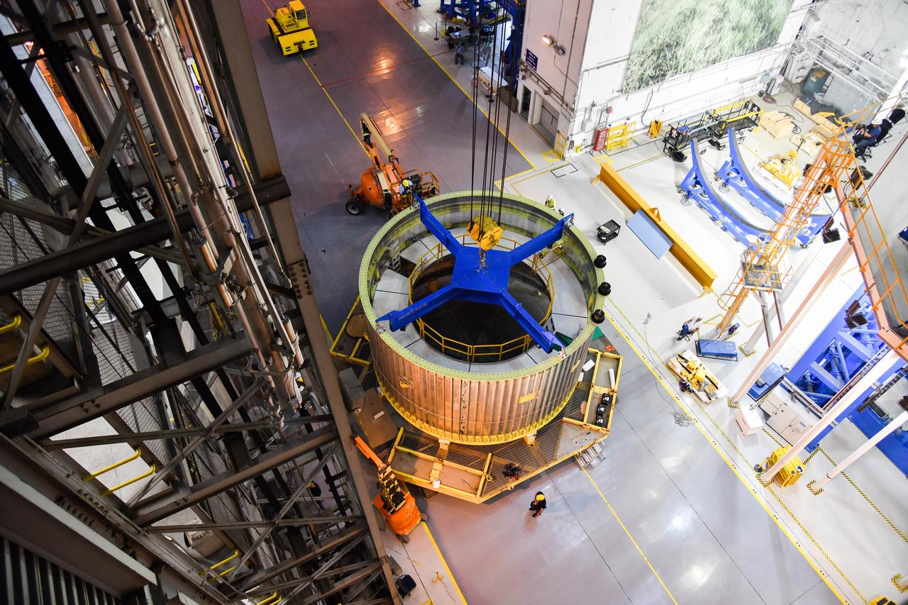
The Space Launch System (SLS) rocket’s liquid oxygen tank structural test article was manufactured and stacked in June 2019 at NASA’s Michoud Assembly Facility in New Orleans. To construct the test article, Boeing technicians at Michoud moved the liquid oxygen tank to the Vertical Assemby Building stacking and integration area. Here, they added simulators to mimic the two structures that connect to the tank, the intertank and the forward skirt. This structural hardware for the SLS core stage for America’s new deep space rocket is structurally identical to the flight version of the tank. It will be shipped on the Pegasus barge to NASA’s Marshall Space Flight Center in Hunstville, Alabama, where it will undergo a series of tests that simulate the stresses and loads of liftoff and flight. These tests will help ensure designs are adequate for successful SLS missions to the Moon and beyond. The flight liquid oxygen tank along with the liquid hydrogen tank supplies more than 500,000 gallons of propellant to the core stages four RS-25 engines, which produce 2 million pounds of thrust to help send the SLS rocket to space.
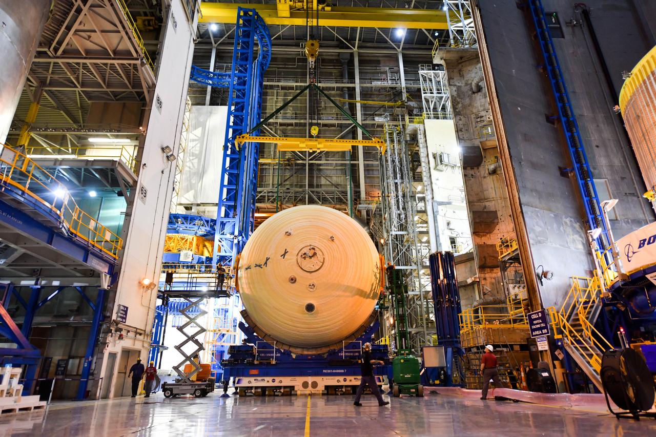
The Space Launch System (SLS) rocket’s liquid oxygen tank structural test article was manufactured and stacked in June 2019 at NASA’s Michoud Assembly Facility in New Orleans. To construct the test article, Boeing technicians at Michoud moved the liquid oxygen tank to the Vertical Assemby Building stacking and integration area. Here, they added simulators to mimic the two structures that connect to the tank, the intertank and the forward skirt. This structural hardware for the SLS core stage for America’s new deep space rocket is structurally identical to the flight version of the tank. It will be shipped on the Pegasus barge to NASA’s Marshall Space Flight Center in Hunstville, Alabama, where it will undergo a series of tests that simulate the stresses and loads of liftoff and flight. These tests will help ensure designs are adequate for successful SLS missions to the Moon and beyond. The flight liquid oxygen tank along with the liquid hydrogen tank supplies more than 500,000 gallons of propellant to the core stages four RS-25 engines, which produce 2 million pounds of thrust to help send the SLS rocket to space.
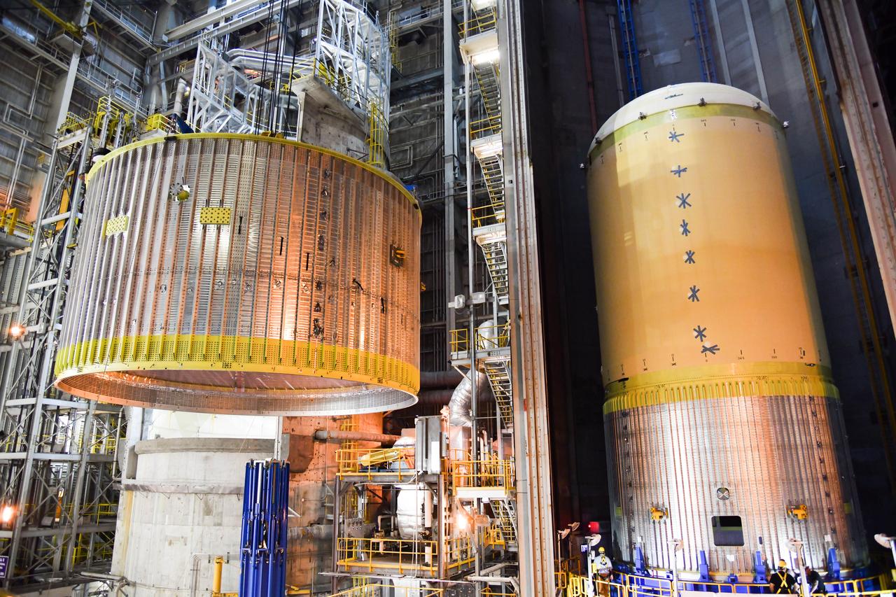
The Space Launch System (SLS) rocket’s liquid oxygen tank structural test article was manufactured and stacked in June 2019 at NASA’s Michoud Assembly Facility in New Orleans. To construct the test article, Boeing technicians at Michoud moved the liquid oxygen tank to the Vertical Assemby Building stacking and integration area. Here, they added simulators to mimic the two structures that connect to the tank, the intertank and the forward skirt. This structural hardware for the SLS core stage for America’s new deep space rocket is structurally identical to the flight version of the tank. It will be shipped on the Pegasus barge to NASA’s Marshall Space Flight Center in Hunstville, Alabama, where it will undergo a series of tests that simulate the stresses and loads of liftoff and flight. These tests will help ensure designs are adequate for successful SLS missions to the Moon and beyond. The flight liquid oxygen tank along with the liquid hydrogen tank supplies more than 500,000 gallons of propellant to the core stages four RS-25 engines, which produce 2 million pounds of thrust to help send the SLS rocket to space.
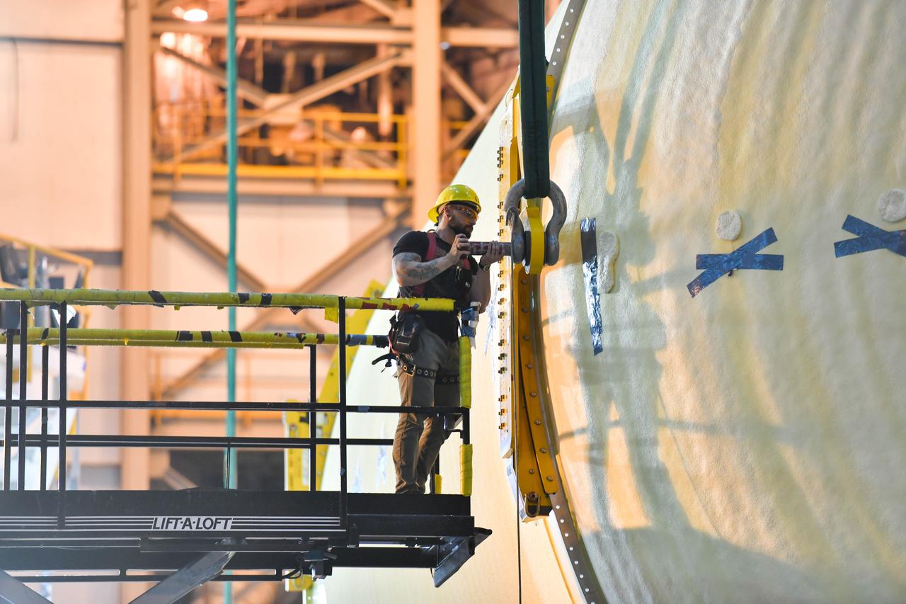
The Space Launch System (SLS) rocket’s liquid oxygen tank structural test article was manufactured and stacked in June 2019 at NASA’s Michoud Assembly Facility in New Orleans. To construct the test article, Boeing technicians at Michoud moved the liquid oxygen tank to the Vertical Assemby Building stacking and integration area. Here, they added simulators to mimic the two structures that connect to the tank, the intertank and the forward skirt. This structural hardware for the SLS core stage for America’s new deep space rocket is structurally identical to the flight version of the tank. It will be shipped on the Pegasus barge to NASA’s Marshall Space Flight Center in Hunstville, Alabama, where it will undergo a series of tests that simulate the stresses and loads of liftoff and flight. These tests will help ensure designs are adequate for successful SLS missions to the Moon and beyond. The flight liquid oxygen tank along with the liquid hydrogen tank supplies more than 500,000 gallons of propellant to the core stages four RS-25 engines, which produce 2 million pounds of thrust to help send the SLS rocket to space.

KENNEDY SPACE CENTER, FLA. -- After arriving at the KSC Shuttle Landing Facility, STS-110 Mission Specialist Jerry Ross smiles in anticipation of his record-breaking seventh Space Shuttle flight, scheduled to launch April 4. Mission STS-110 is the 13th assembly flight to the International Space Station. During four planned spacewalks, Ross and other crew members will install the S0 Integrated Truss Structure (ITS), centerpiece of the orbiting International Space Station (ISS), at the center of the 10-truss, girderlike structure that will ultimately extend the length of a football field on the ISS. The S0 truss will be attached to the U.S. Lab, "Destiny," on the 11-day mission