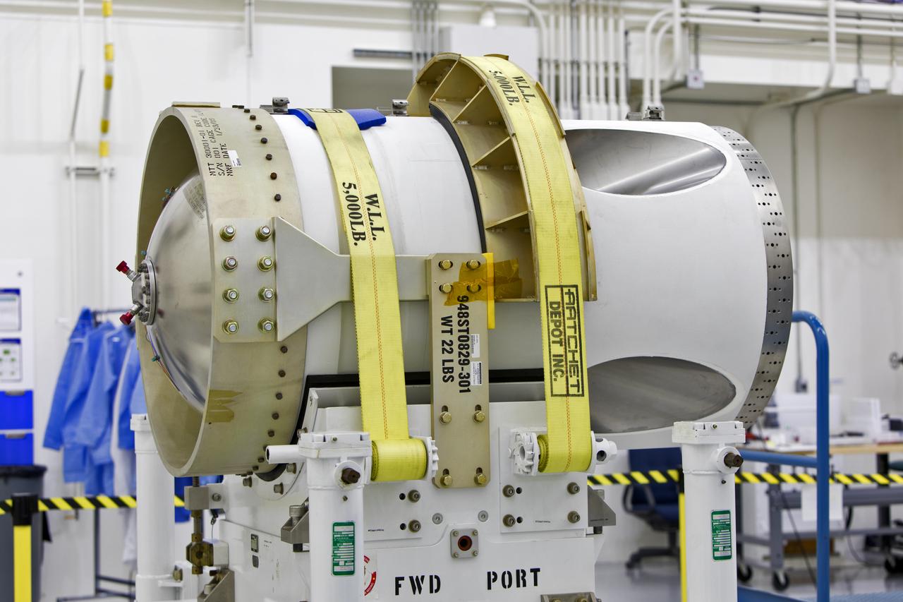
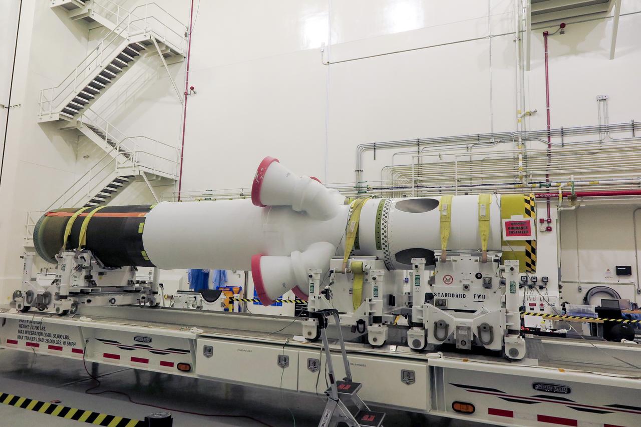
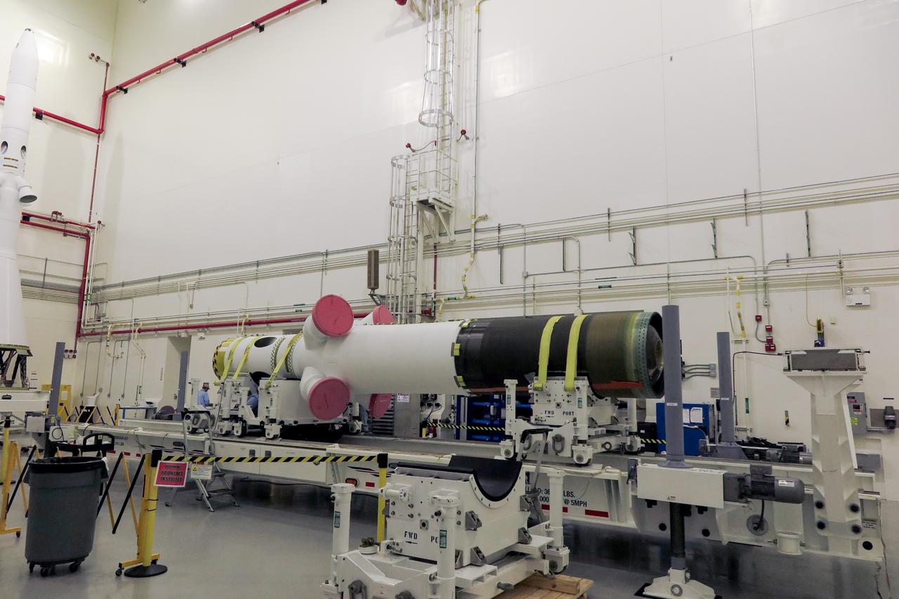
The jettison motor for Orion’s Launch Abort System (LAS) is shown inside the Launch Abort System Facility (LASF) at NASA’s Kennedy Space Center in Florida. The motor, which arrived at Kennedy on Sept. 10, 2018, will be stored in the LASF until processing for a full-stress test of the LAS called Ascent Abort-2 (AA-2), scheduled for April 2019. Designed and built by NASA and Lockheed Martin, the LAS will protect astronauts if a problem arises during launch by pulling the spacecraft away from a failing rocket. The jettison motor is one of three solid propellant rocket motors in the LAS (the abort motor and attitude control motor are the other two). The jettison motor will pull the LAS away from the crew module, allowing Orion’s parachutes to deploy and the spacecraft to safely land in the ocean.
The jettison motor for Orion’s Launch Abort System (LAS) is shown inside the Launch Abort System Facility (LASF) at NASA’s Kennedy Space Center in Florida. The motor, which arrived at Kennedy on Sept. 10, 2018, will be stored in the LASF until processing for a full-stress test of the LAS called Ascent Abort-2 (AA-2), scheduled for April 2019. Designed and built by NASA and Lockheed Martin, the LAS will protect astronauts if a problem arises during launch by pulling the spacecraft away from a failing rocket. The jettison motor is one of three solid propellant rocket motors in the LAS (the abort motor and attitude control motor are the other two). The jettison motor will pull the LAS away from the crew module, allowing Orion’s parachutes to deploy and the spacecraft to safely land in the ocean.
The jettison motor for Orion’s Launch Abort System (LAS) is shown inside the Launch Abort System Facility (LASF) at NASA’s Kennedy Space Center in Florida. The motor, which arrived at Kennedy on Sept. 10, 2018, will be stored in the LASF until processing for a full-stress test of the LAS called Ascent Abort-2 (AA-2), scheduled for April 2019. Designed and built by NASA and Lockheed Martin, the LAS will protect astronauts if a problem arises during launch by pulling the spacecraft away from a failing rocket. The jettison motor is one of three solid propellant rocket motors in the LAS (the abort motor and attitude control motor are the other two). The jettison motor will pull the LAS away from the crew module, allowing Orion’s parachutes to deploy and the spacecraft to safely land in the ocean.
The jettison motor for Orion’s Launch Abort System (LAS) is shown inside the Launch Abort System Facility (LASF) at NASA’s Kennedy Space Center in Florida. The motor, which arrived at Kennedy on Sept. 10, 2018, will be stored in the LASF until processing for a full-stress test of the LAS called Ascent Abort-2 (AA-2), scheduled for April 2019. Designed and built by NASA and Lockheed Martin, the LAS will protect astronauts if a problem arises during launch by pulling the spacecraft away from a failing rocket. The jettison motor is one of three solid propellant rocket motors in the LAS (the abort motor and attitude control motor are the other two). The jettison motor will pull the LAS away from the crew module, allowing Orion’s parachutes to deploy and the spacecraft to safely land in the ocean.
The jettison motor for Orion’s Launch Abort System (LAS) is shown inside the Launch Abort System Facility (LASF) at NASA’s Kennedy Space Center in Florida. The motor, which arrived at Kennedy on Sept. 10, 2018, will be stored in the LASF until processing for a full-stress test of the LAS called Ascent Abort-2 (AA-2), scheduled for April 2019. Designed and built by NASA and Lockheed Martin, the LAS will protect astronauts if a problem arises during launch by pulling the spacecraft away from a failing rocket. The jettison motor is one of three solid propellant rocket motors in the LAS (the abort motor and attitude control motor are the other two). The jettison motor will pull the LAS away from the crew module, allowing Orion’s parachutes to deploy and the spacecraft to safely land in the ocean.
The jettison motor for Orion’s Launch Abort System (LAS) is shown inside the Launch Abort System Facility (LASF) at NASA’s Kennedy Space Center in Florida. The motor, which arrived at Kennedy on Sept. 10, 2018, will be stored in the LASF until processing for a full-stress test of the LAS called Ascent Abort-2 (AA-2), scheduled for April 2019. Designed and built by NASA and Lockheed Martin, the LAS will protect astronauts if a problem arises during launch by pulling the spacecraft away from a failing rocket. The jettison motor is one of three solid propellant rocket motors in the LAS (the abort motor and attitude control motor are the other two). The jettison motor will pull the LAS away from the crew module, allowing Orion’s parachutes to deploy and the spacecraft to safely land in the ocean.
The jettison motor for Orion’s Launch Abort System (LAS) is shown inside the Launch Abort System Facility (LASF) at NASA’s Kennedy Space Center in Florida. The motor, which arrived at Kennedy on Sept. 10, 2018, will be stored in the LASF until processing for a full-stress test of the LAS called Ascent Abort-2 (AA-2), scheduled for April 2019. Designed and built by NASA and Lockheed Martin, the LAS will protect astronauts if a problem arises during launch by pulling the spacecraft away from a failing rocket. The jettison motor is one of three solid propellant rocket motors in the LAS (the abort motor and attitude control motor are the other two). The jettison motor will pull the LAS away from the crew module, allowing Orion’s parachutes to deploy and the spacecraft to safely land in the ocean.
The jettison motor for Orion’s Launch Abort System (LAS) is shown inside the Launch Abort System Facility (LASF) at NASA’s Kennedy Space Center in Florida. The motor, which arrived at Kennedy on Sept. 10, 2018, will be stored in the LASF until processing for a full-stress test of the LAS called Ascent Abort-2 (AA-2), scheduled for April 2019. Designed and built by NASA and Lockheed Martin, the LAS will protect astronauts if a problem arises during launch by pulling the spacecraft away from a failing rocket. The jettison motor is one of three solid propellant rocket motors in the LAS (the abort motor and attitude control motor are the other two). The jettison motor will pull the LAS away from the crew module, allowing Orion’s parachutes to deploy and the spacecraft to safely land in the ocean.
The jettison motor for Orion’s Launch Abort System (LAS) is shown inside the Launch Abort System Facility (LASF) at NASA’s Kennedy Space Center in Florida. The motor, which arrived at Kennedy on Sept. 10, 2018, will be stored in the LASF until processing for a full-stress test of the LAS called Ascent Abort-2 (AA-2), scheduled for April 2019. Designed and built by NASA and Lockheed Martin, the LAS will protect astronauts if a problem arises during launch by pulling the spacecraft away from a failing rocket. The jettison motor is one of three solid propellant rocket motors in the LAS (the abort motor and attitude control motor are the other two). The jettison motor will pull the LAS away from the crew module, allowing Orion’s parachutes to deploy and the spacecraft to safely land in the ocean.
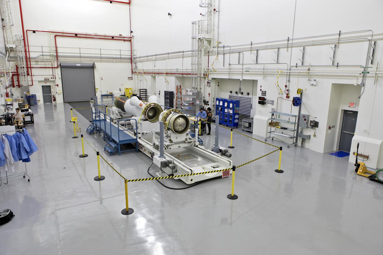
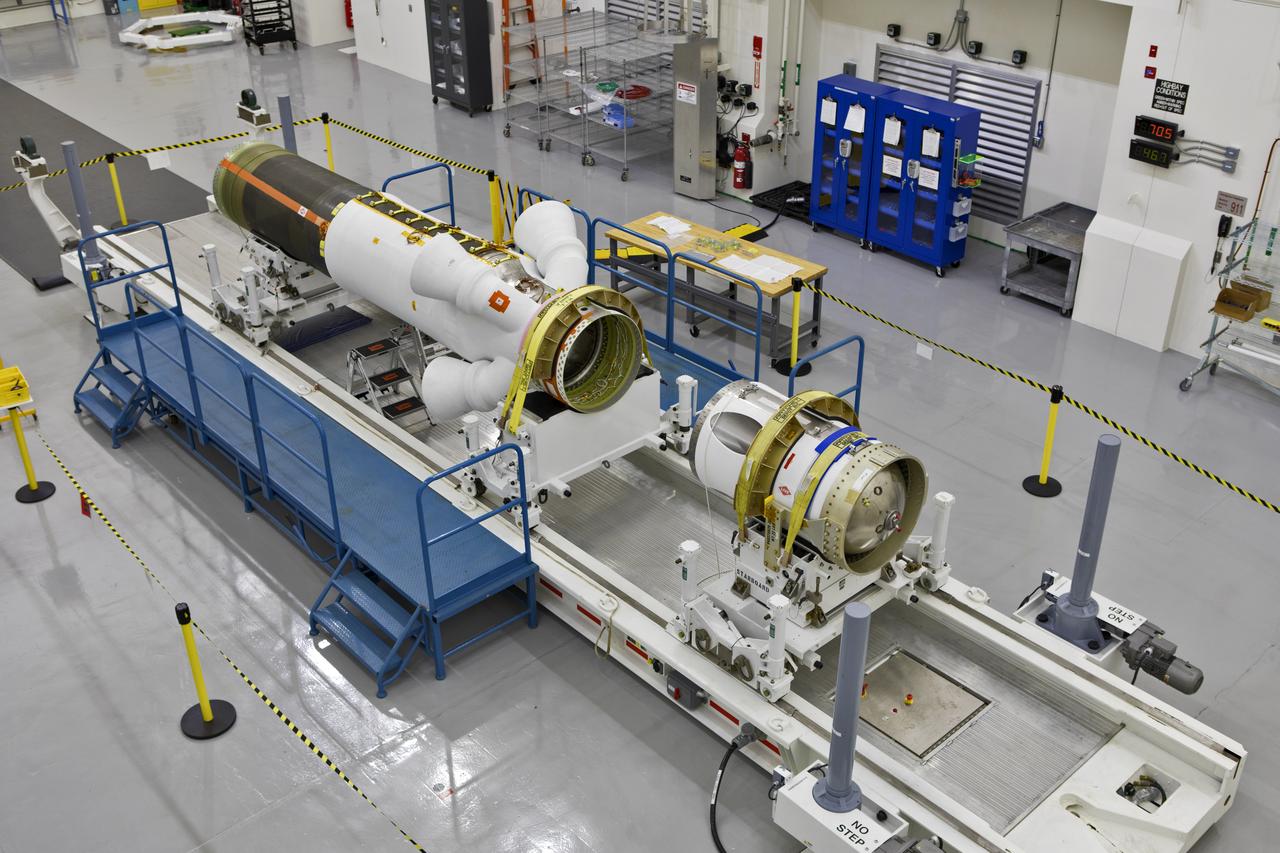
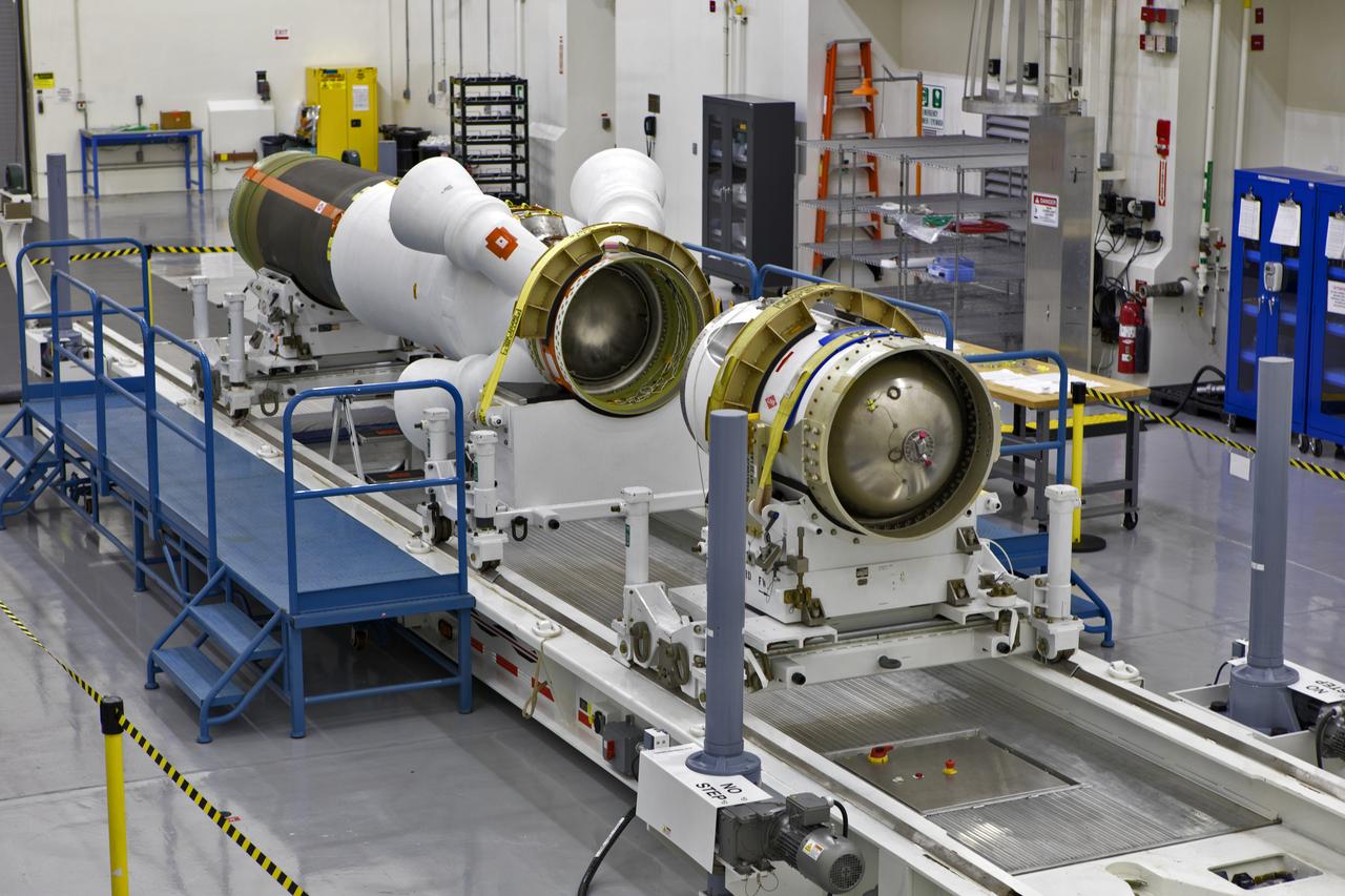
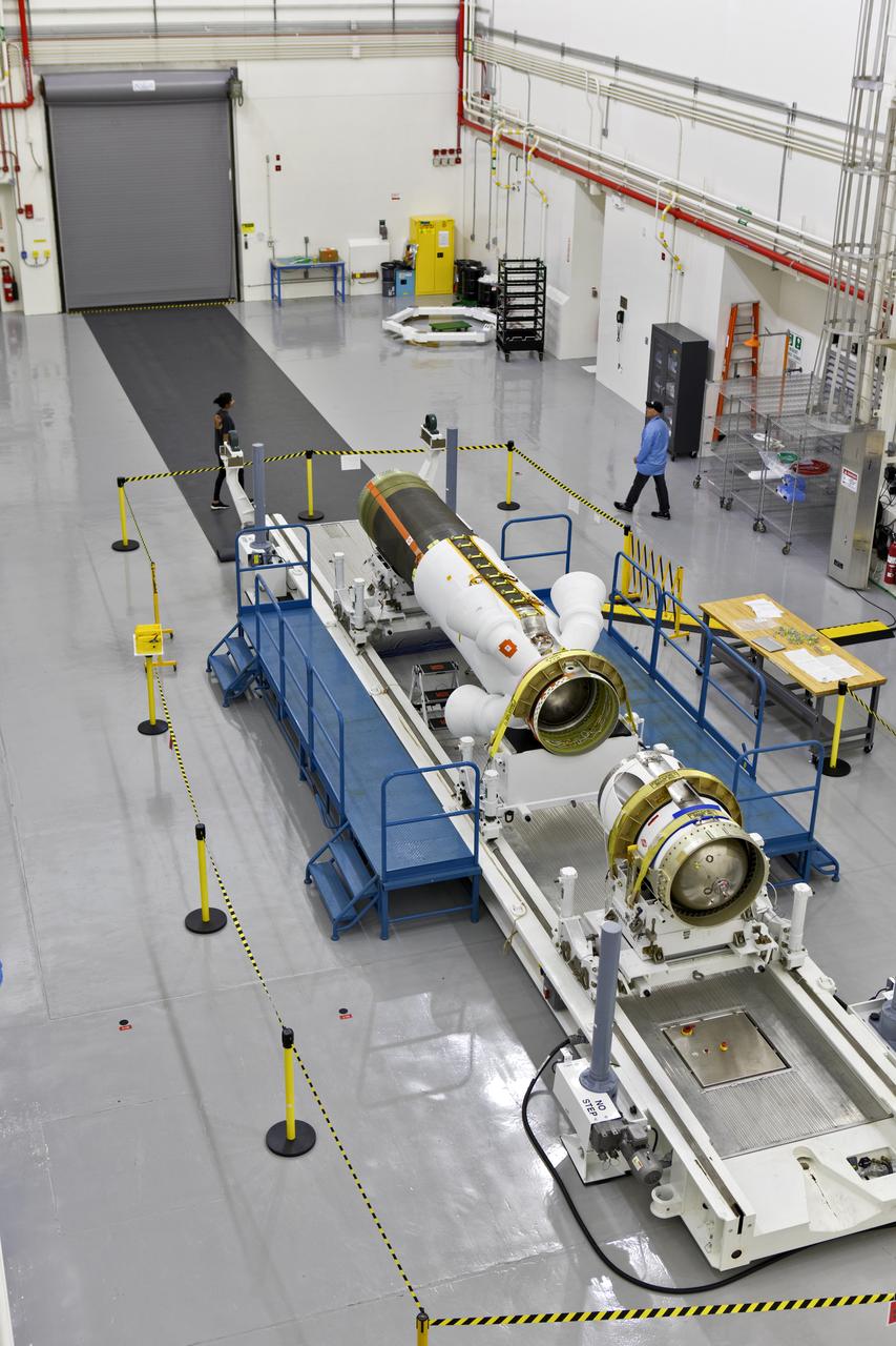
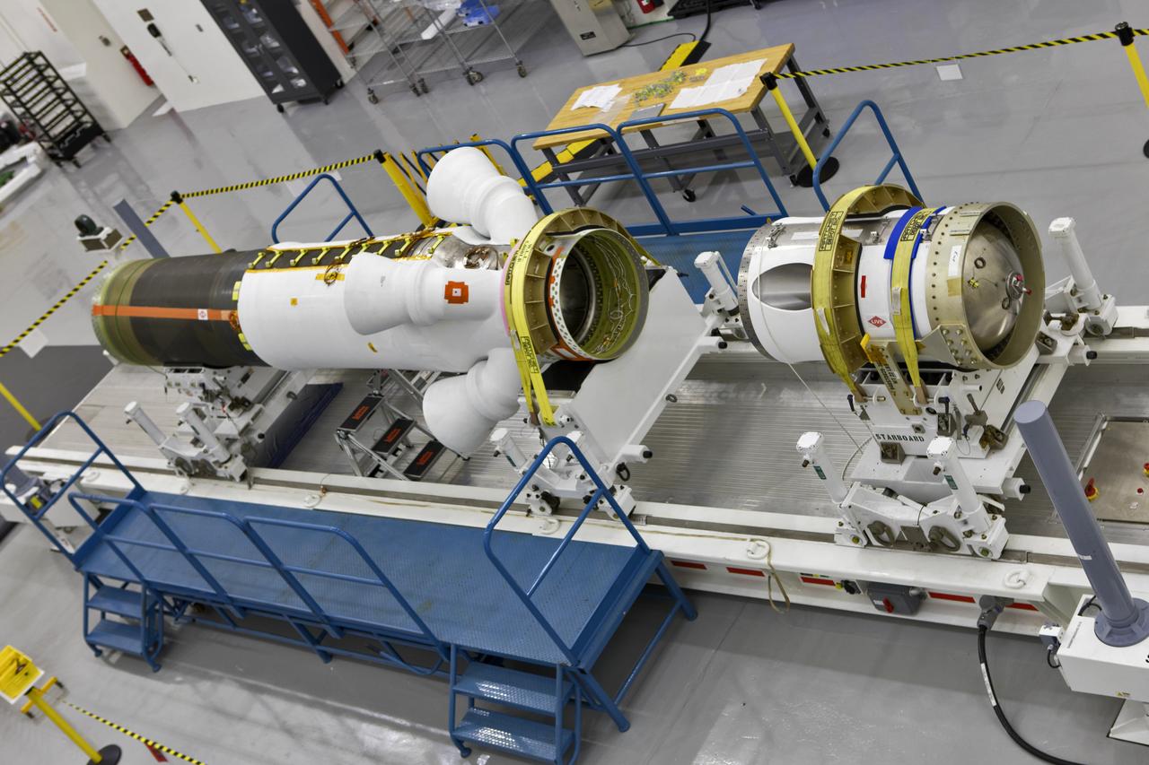
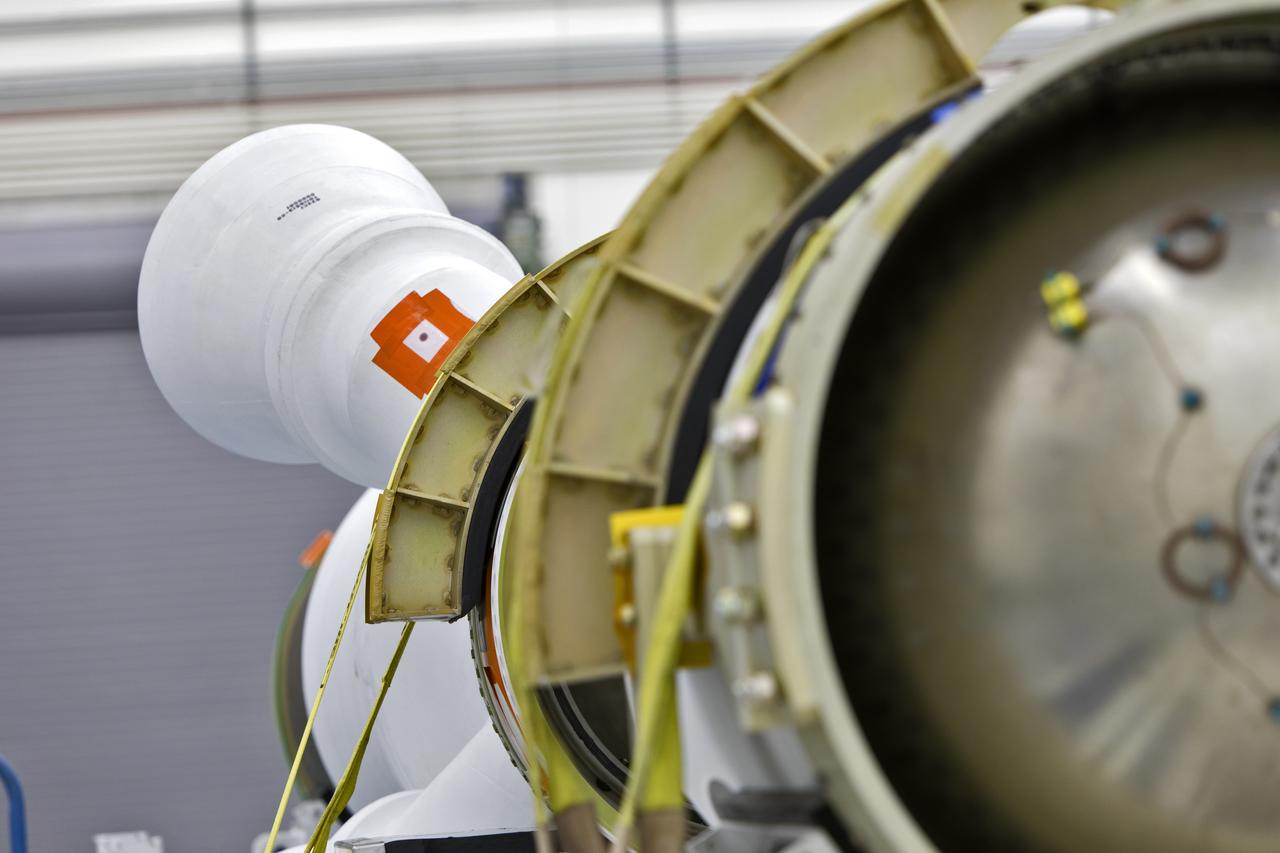
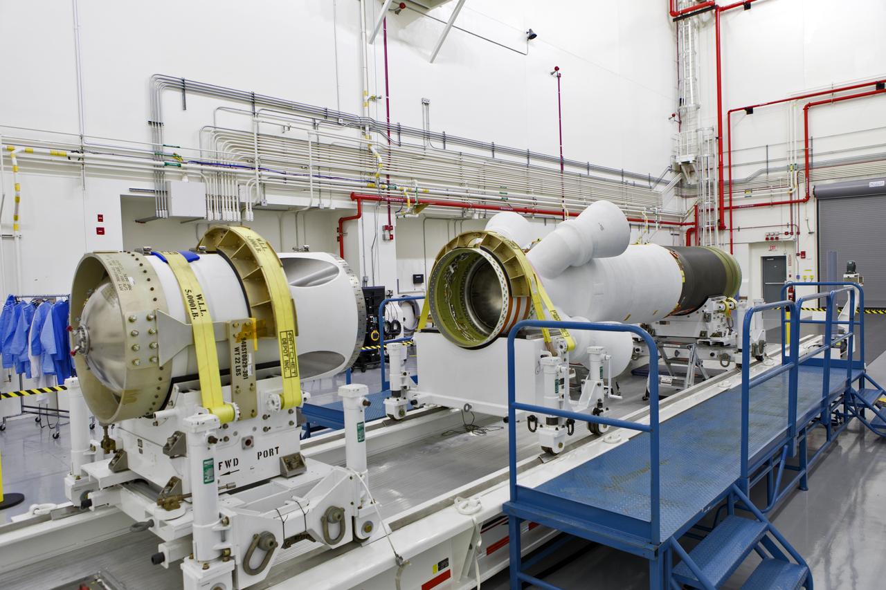
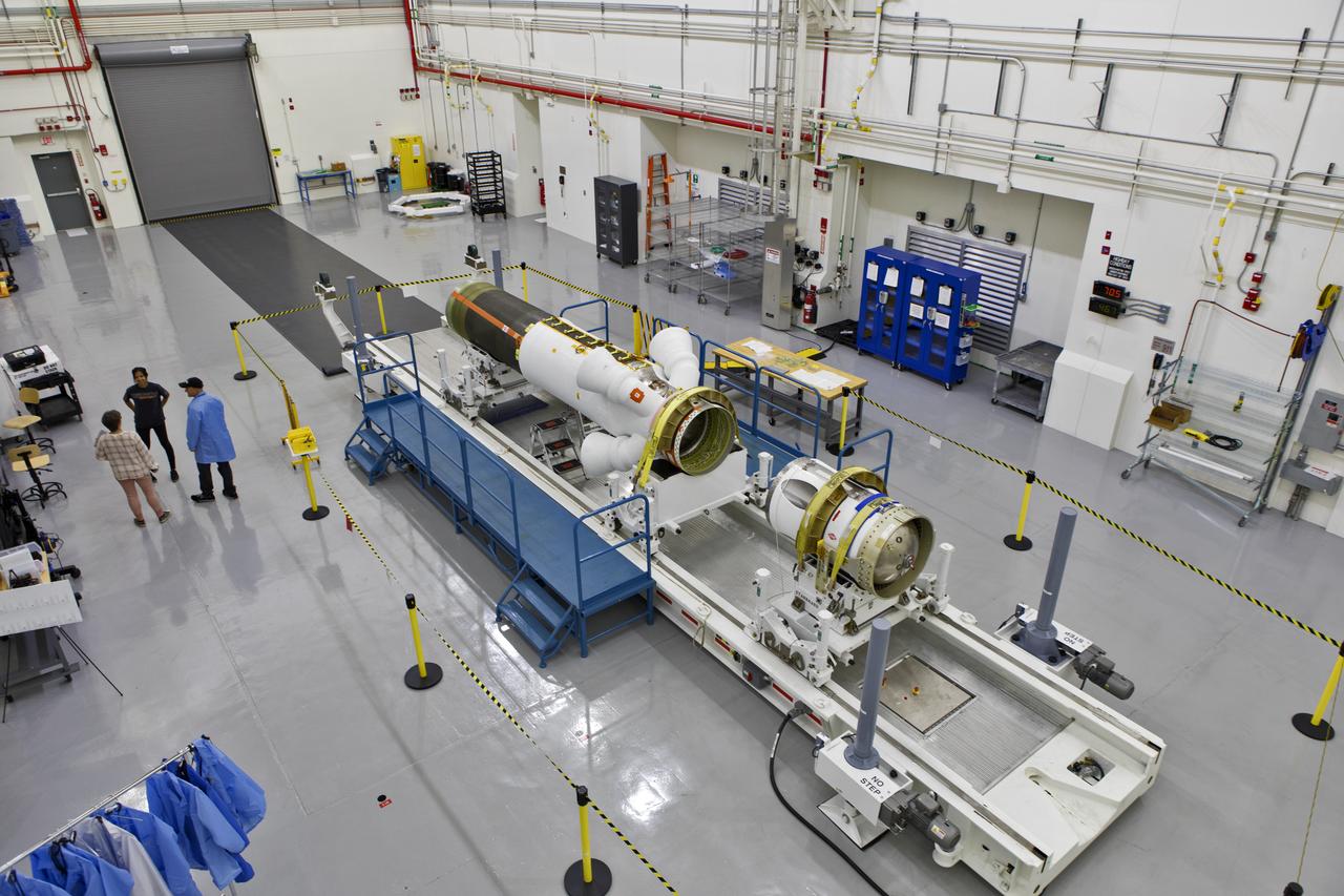
The launch abort motor is integrated with the jettison motor for Orion’s launch abort system (LAS) for Artemis II, inside the Launch Abort System Facility at NASA’s Kennedy Space Center in Florida on April 15, 2020. The launch abort and jettison motors are two of three motors on the LAS. The LAS will be positioned atop the Orion crew module and is designed to protect astronauts if a problem arises during launch by pulling the spacecraft away from a failing rocket. Artemis II will take the first humans in orbit around the Moon in the 21st century.
S66-62999 (13 Nov. 1966) --- Jettison of the extravehicular life support system (ELSS) and other equipment from the Gemini-12 spacecraft during its rendezvous mission in space. The nose of the Gemini-12 spacecraft is clearly visible at right edge of photo. Photo credit: NASA
The launch abort motor is integrated with the jettison motor for Orion’s launch abort system (LAS) for Artemis II, inside the Launch Abort System Facility at NASA’s Kennedy Space Center in Florida on April 15, 2020. The launch abort and jettison motors are two of three motors on the LAS. The LAS will be positioned atop the Orion crew module and is designed to protect astronauts if a problem arises during launch by pulling the spacecraft away from a failing rocket. Artemis II will take the first humans in orbit around the Moon in the 21st century. In view, at far left, is the Launch Abort System for Artemis I, the first uncrewed mission of Orion atop the Space Launch System rocket.
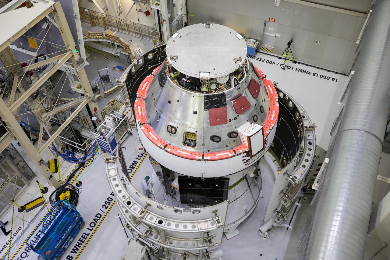
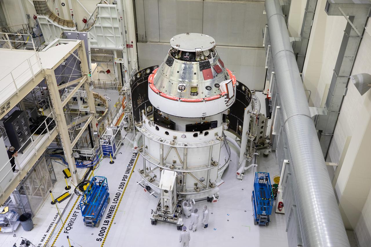
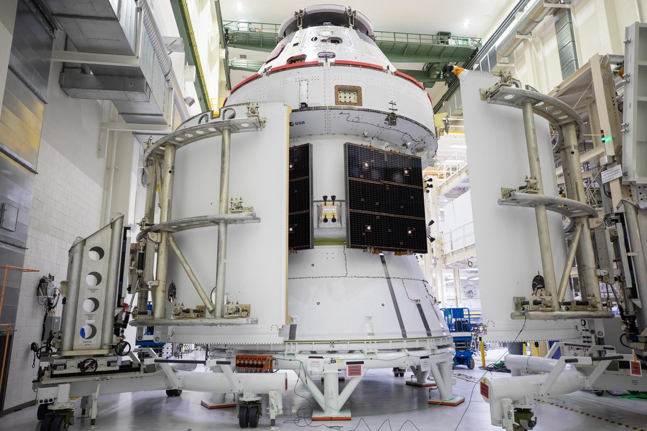
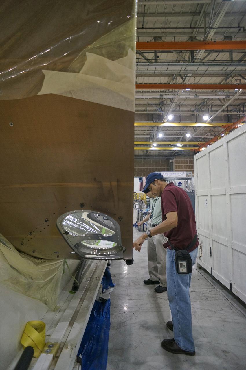
The spacecraft adapter jettison fairing panels are secured onto Orion’s European Service Module (ESM) on Oct. 27, 2020, inside the Neil Armstrong Operations and Checkout Building (O&C) at NASA’s Kennedy Space Center in Florida. The three panels were inspected and moved into place for installation by technicians with Lockheed Martin. Recently, teams from across the globe installed the four solar array wings, which are housed inside the protective covering of the fairings. The fairing panels will encapsulate the ESM to protect it from harsh environments such as heat, wind, and acoustics as the spacecraft is propelled out of Earth’s atmosphere atop the Space Launch System rocket during NASA’s Artemis I mission.
The spacecraft adapter jettison fairing panels are secured onto Orion’s European Service Module (ESM) on Oct. 27, 2020, inside the Neil Armstrong Operations and Checkout Building (O&C) at NASA’s Kennedy Space Center in Florida. The three panels were inspected and moved into place for installation by technicians with Lockheed Martin. Recently, teams from across the globe installed the four solar array wings, which are housed inside the protective covering of the fairings. The fairing panels will encapsulate the ESM to protect it from harsh environments such as heat, wind, and acoustics as the spacecraft is propelled out of Earth’s atmosphere atop the Space Launch System rocket during NASA’s Artemis I mission.
The spacecraft adapter jettison fairing panels are secured onto Orion’s European Service Module (ESM) on Oct. 27, 2020, inside the Neil Armstrong Operations and Checkout Building (O&C) at NASA’s Kennedy Space Center in Florida. The three panels were inspected and moved into place for installation by technicians with Lockheed Martin. Recently, teams from across the globe installed the four solar array wings, which are housed inside the protective covering of the fairings. The fairing panels will encapsulate the ESM to protect it from harsh environments such as heat, wind, and acoustics as the spacecraft is propelled out of Earth’s atmosphere atop the Space Launch System rocket during NASA’s Artemis I mission.
The spacecraft adapter jettison fairing panels are secured onto Orion’s European Service Module (ESM) on Oct. 27, 2020, inside the Neil Armstrong Operations and Checkout Building (O&C) at NASA’s Kennedy Space Center in Florida. The three panels were inspected and moved into place for installation by technicians with Lockheed Martin. Recently, teams from across the globe installed the four solar array wings, which are housed inside the protective covering of the fairings. The fairing panels will encapsulate the ESM to protect it from harsh environments such as heat, wind, and acoustics as the spacecraft is propelled out of Earth’s atmosphere atop the Space Launch System rocket during NASA’s Artemis I mission.
Orion's forward bay cover is jettisoned on its first flight test, Exploration Flight Test-1 (EFT-1), on December 5, 2014.
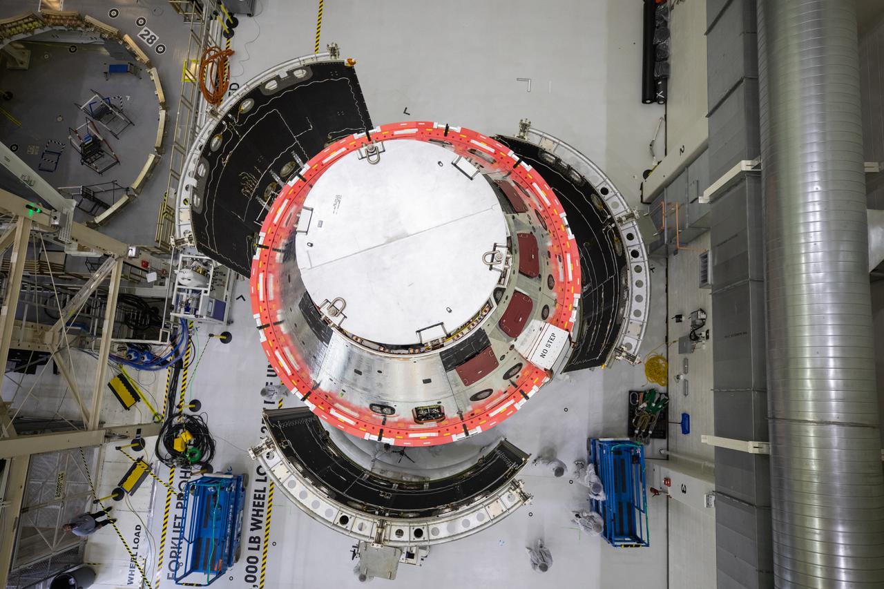
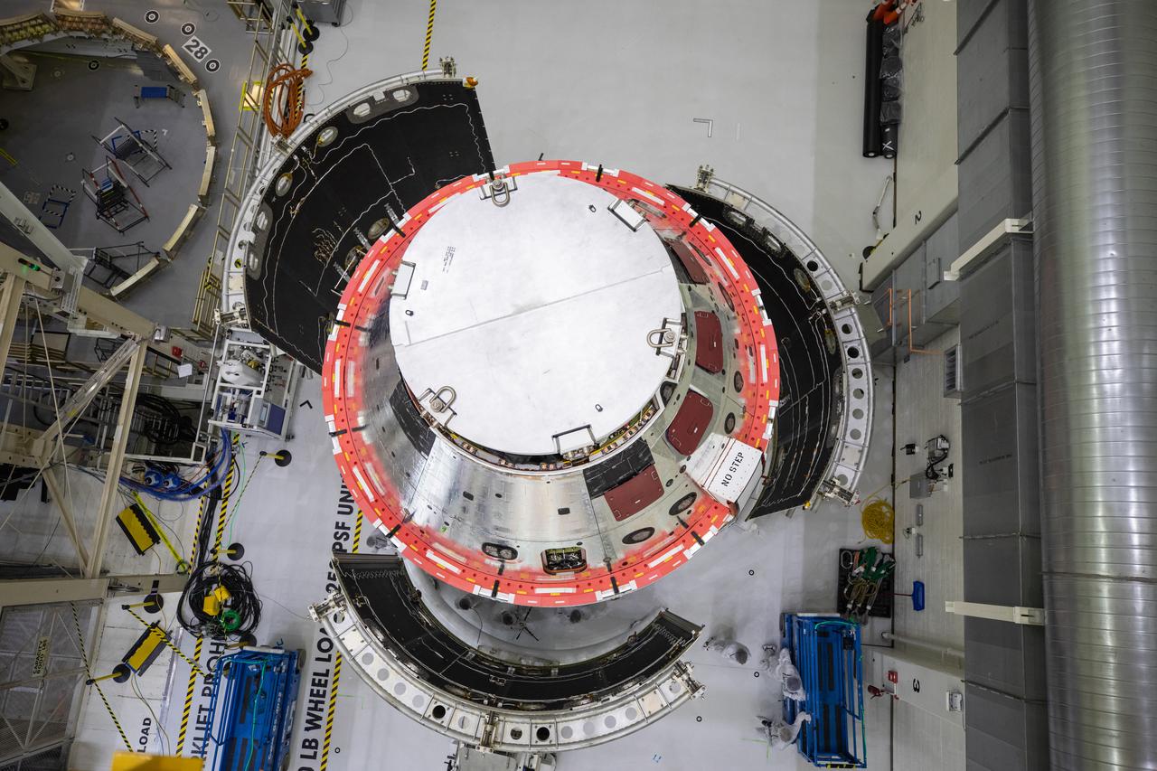
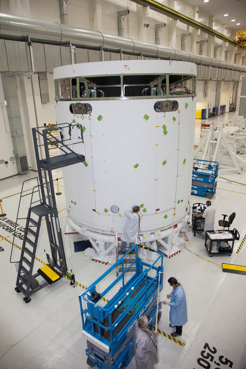
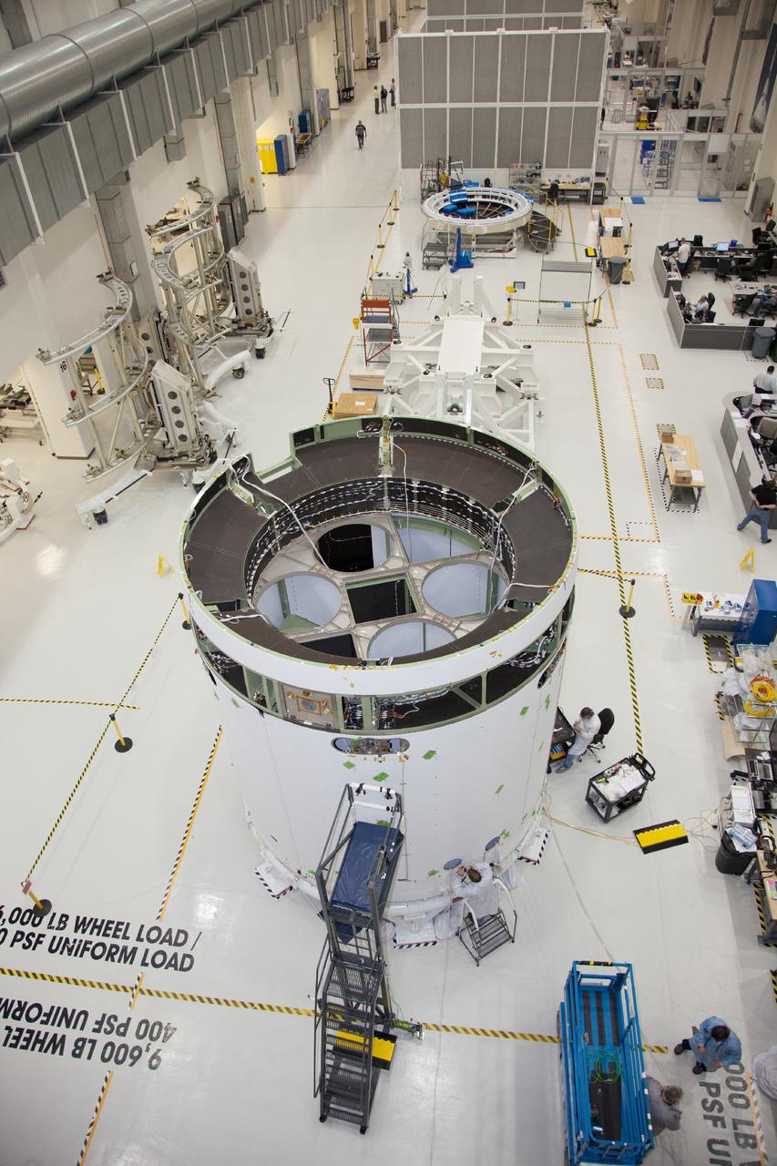
Shown is an overhead view of three spacecraft adapter jettison fairing panels fitted onto Orion’s European Service Module (ESM) on Oct. 13, 2020, inside the Neil Armstrong Operations and Checkout Building (O&C) at NASA’s Kennedy Space Center in Florida. The panels were inspected and moved into place for installation by technicians with Lockheed Martin. Recently, teams from across the globe installed the four solar array wings, which are housed inside the protective covering of the fairings. Once secured, they will encapsulate the ESM to protect it from harsh environments such as heat, wind, and acoustics as the spacecraft is propelled out of Earth’s atmosphere atop the Space Launch System (SLS) rocket during NASA’s Artemis I mission.
Shown is an overhead view of three spacecraft adapter jettison fairing panels fitted onto Orion’s European Service Module (ESM) on Oct. 13, 2020, inside the Neil Armstrong Operations and Checkout Building (O&C) at NASA’s Kennedy Space Center in Florida. The panels were inspected and moved into place for installation by technicians with Lockheed Martin. Recently, teams from across the globe installed the four solar array wings, which are housed inside the protective covering of the fairings. Once secured, they will encapsulate the ESM to protect it from harsh environments such as heat, wind, and acoustics as the spacecraft is propelled out of Earth’s atmosphere atop the Space Launch System (SLS) rocket during NASA’s Artemis I mission.
Shown is an overhead view of three spacecraft adapter jettison fairing panels fitted onto Orion’s European Service Module (ESM) on Oct. 13, 2020, inside the Neil Armstrong Operations and Checkout Building (O&C) at NASA’s Kennedy Space Center in Florida. The panels were inspected and moved into place for installation by technicians with Lockheed Martin. Recently, teams from across the globe installed the four solar array wings, which are housed inside the protective covering of the fairings. Once secured, they will encapsulate the ESM to protect it from harsh environments such as heat, wind, and acoustics as the spacecraft is propelled out of Earth’s atmosphere atop the Space Launch System (SLS) rocket during NASA’s Artemis I mission.
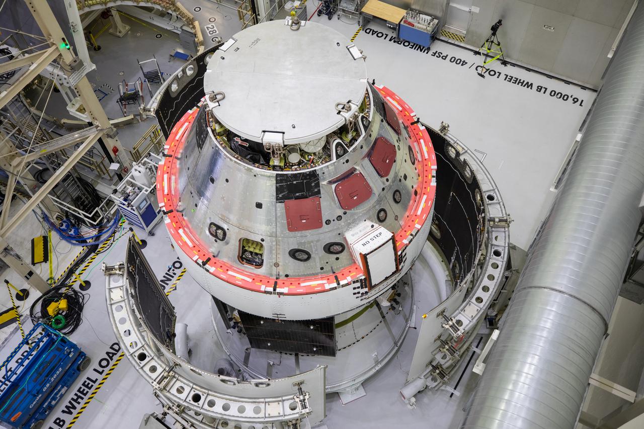
Shown is an overhead view of three spacecraft adapter jettison fairing panels fitted onto Orion’s European Service Module (ESM) on Oct. 13, 2020, inside the Neil Armstrong Operations and Checkout Building (O&C) at NASA’s Kennedy Space Center in Florida. The panels were inspected and moved into place for installation by technicians with Lockheed Martin. Recently, teams from across the globe installed the four solar array wings, which are housed inside the protective covering of the fairings. Once secured, they will encapsulate the ESM to protect it from harsh environments such as heat, wind, and acoustics as the spacecraft is propelled out of Earth’s atmosphere atop the Space Launch System (SLS) rocket during NASA’s Artemis I mission.
Shown is an overhead view of three spacecraft adapter jettison fairing panels fitted onto Orion’s European Service Module (ESM) on Oct. 13, 2020, inside the Neil Armstrong Operations and Checkout Building (O&C) at NASA’s Kennedy Space Center in Florida. The panels were inspected and moved into place for installation by technicians with Lockheed Martin. Recently, teams from across the globe installed the four solar array wings, which are housed inside the protective covering of the fairings. Once secured, they will encapsulate the ESM to protect it from harsh environments such as heat, wind, and acoustics as the spacecraft is propelled out of Earth’s atmosphere atop the Space Launch System (SLS) rocket during NASA’s Artemis I mission.
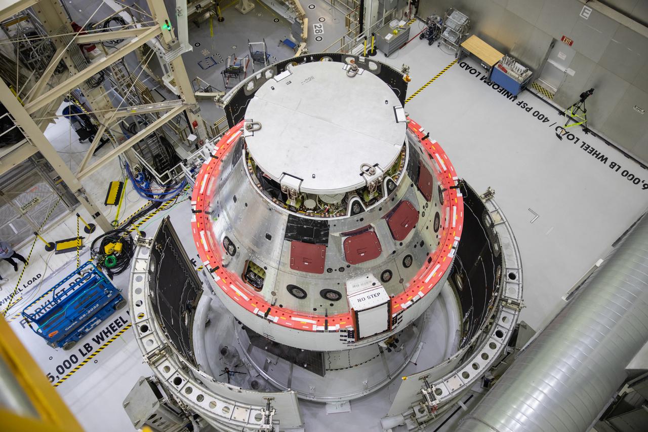
Shown is an overhead view of three spacecraft adapter jettison fairing panels fitted onto Orion’s European Service Module (ESM) on Oct. 13, 2020, inside the Neil Armstrong Operations and Checkout Building (O&C) at NASA’s Kennedy Space Center in Florida. The panels were inspected and moved into place for installation by technicians with Lockheed Martin. Recently, teams from across the globe installed the four solar array wings, which are housed inside the protective covering of the fairings. Once secured, they will encapsulate the ESM to protect it from harsh environments such as heat, wind, and acoustics as the spacecraft is propelled out of Earth’s atmosphere atop the Space Launch System (SLS) rocket during NASA’s Artemis I mission.
Shown is an overhead view of three spacecraft adapter jettison fairing panels fitted onto Orion’s European Service Module (ESM) on Oct. 13, 2020, inside the Neil Armstrong Operations and Checkout Building (O&C) at NASA’s Kennedy Space Center in Florida. The panels were inspected and moved into place for installation by technicians with Lockheed Martin. Recently, teams from across the globe installed the four solar array wings, which are housed inside the protective covering of the fairings. Once secured, they will encapsulate the ESM to protect it from harsh environments such as heat, wind, and acoustics as the spacecraft is propelled out of Earth’s atmosphere atop the Space Launch System (SLS) rocket during NASA’s Artemis I mission.
Shown is an overhead view of three spacecraft adapter jettison fairing panels fitted onto Orion’s European Service Module (ESM) on Oct. 13, 2020, inside the Neil Armstrong Operations and Checkout Building (O&C) at NASA’s Kennedy Space Center in Florida. The panels were inspected and moved into place for installation by technicians with Lockheed Martin. Recently, teams from across the globe installed the four solar array wings, which are housed inside the protective covering of the fairings. Once secured, they will encapsulate the ESM to protect it from harsh environments such as heat, wind, and acoustics as the spacecraft is propelled out of Earth’s atmosphere atop the Space Launch System (SLS) rocket during NASA’s Artemis I mission.
Shown is an overhead view of three spacecraft adapter jettison fairing panels fitted onto Orion’s European Service Module (ESM) on Oct. 13, 2020, inside the Neil Armstrong Operations and Checkout Building (O&C) at NASA’s Kennedy Space Center in Florida. The panels were inspected and moved into place for installation by technicians with Lockheed Martin. Recently, teams from across the globe installed the four solar array wings, which are housed inside the protective covering of the fairings. Once secured, they will encapsulate the ESM to protect it from harsh environments such as heat, wind, and acoustics as the spacecraft is propelled out of Earth’s atmosphere atop the Space Launch System (SLS) rocket during NASA’s Artemis I mission.
Shown is an overhead view of three spacecraft adapter jettison fairing panels fitted onto Orion’s European Service Module (ESM) on Oct. 13, 2020, inside the Neil Armstrong Operations and Checkout Building (O&C) at NASA’s Kennedy Space Center in Florida. The panels were inspected and moved into place for installation by technicians with Lockheed Martin. Recently, teams from across the globe installed the four solar array wings, which are housed inside the protective covering of the fairings. Once secured, they will encapsulate the ESM to protect it from harsh environments such as heat, wind, and acoustics as the spacecraft is propelled out of Earth’s atmosphere atop the Space Launch System (SLS) rocket during NASA’s Artemis I mission.
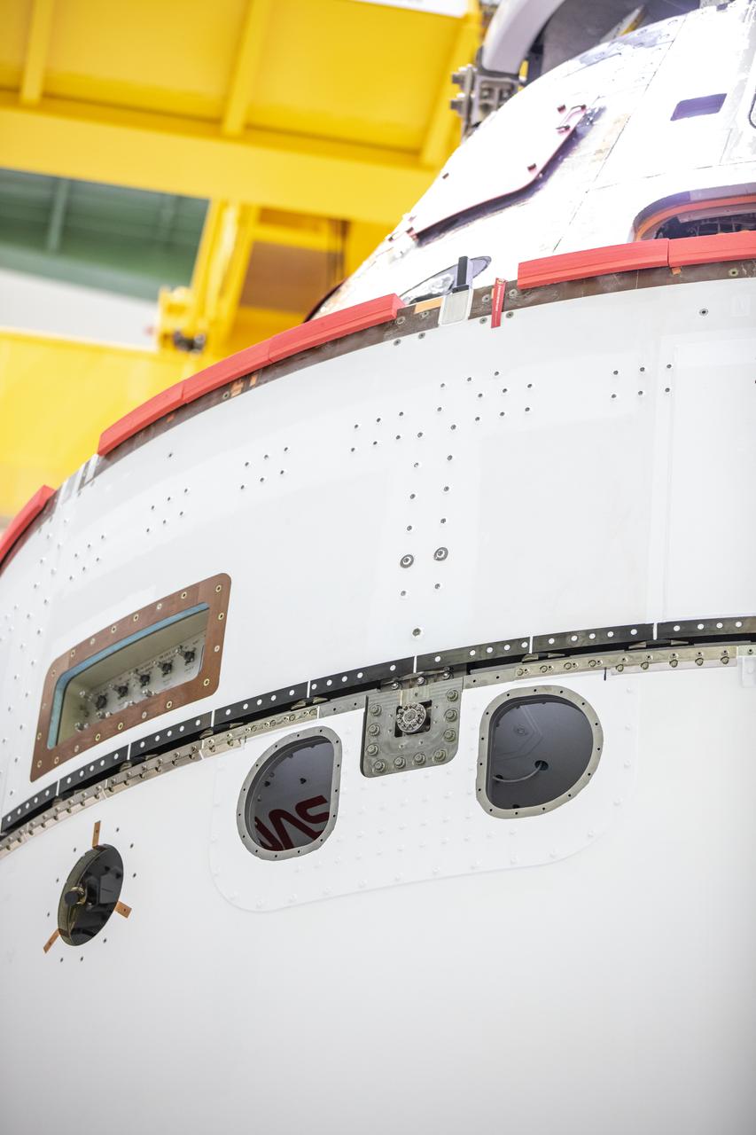
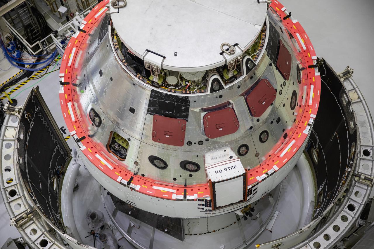
A close-up view of the Orion’s crew module adapter with the spacecraft adapter jettison fairing panels secured in place shows a peak of the iconic NASA worm insignia on Oct. 27, 2020, inside the Neil Armstrong Operations and Checkout Building (O&C) at NASA’s Kennedy Space Center in Florida. The panels were inspected and moved into place for installation by technicians with Lockheed Martin. Recently, teams from across the globe installed the four solar array wings, which are housed inside the protective covering of the fairings. Once secured, they will encapsulate the ESM to protect it from harsh environments such as heat, wind, and acoustics as the spacecraft is propelled out of Earth’s atmosphere atop the Space Launch System (SLS) rocket during NASA’s Artemis I mission.
Shown is an overhead view of three spacecraft adapter jettison fairing panels fitted onto Orion’s European Service Module (ESM) on Oct. 13, 2020, inside the Neil Armstrong Operations and Checkout Building (O&C) at NASA’s Kennedy Space Center in Florida. The panels were inspected and moved into place for installation by technicians with Lockheed Martin. Recently, teams from across the globe installed the four solar array wings, which are housed inside the protective covering of the fairings. Once secured, they will encapsulate the ESM to protect it from harsh environments such as heat, wind, and acoustics as the spacecraft is propelled out of Earth’s atmosphere atop the Space Launch System (SLS) rocket during NASA’s Artemis I mission.
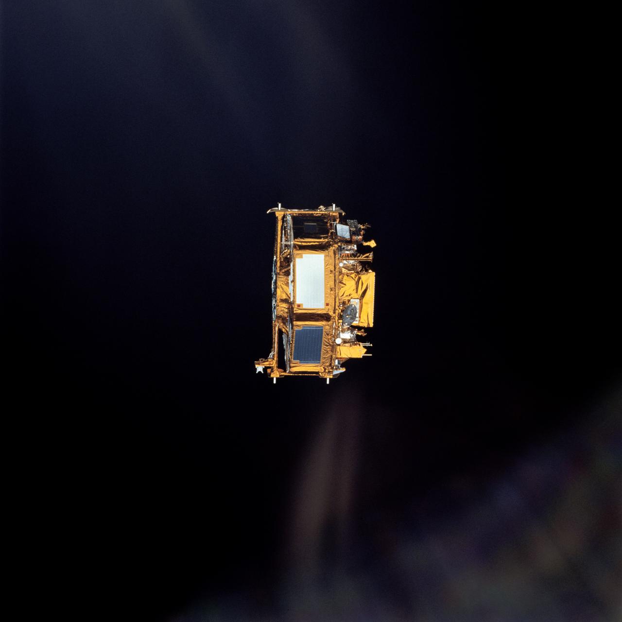
STS072-720-076 (13 Jan. 1996) --- The crewmembers captured this 35mm view of the Japanese Space Flyer Unit (SFU) following the jettisoning of the solar panels. Later they used the Remote Manipulator System (RMS) to latch onto the satellite and berth it in the Space Shuttle Endeavour's aft cargo bay.
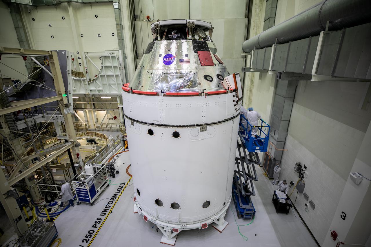
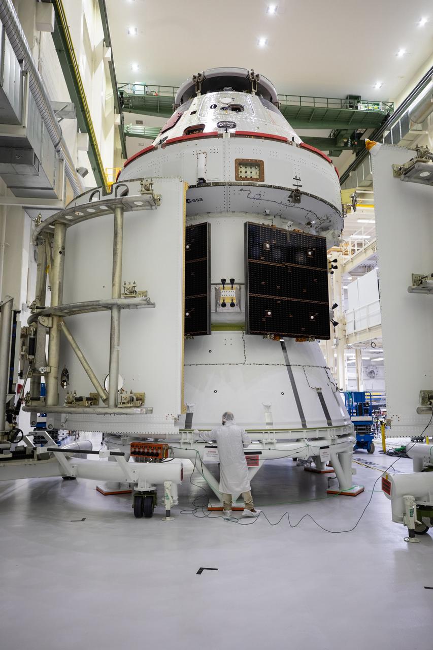
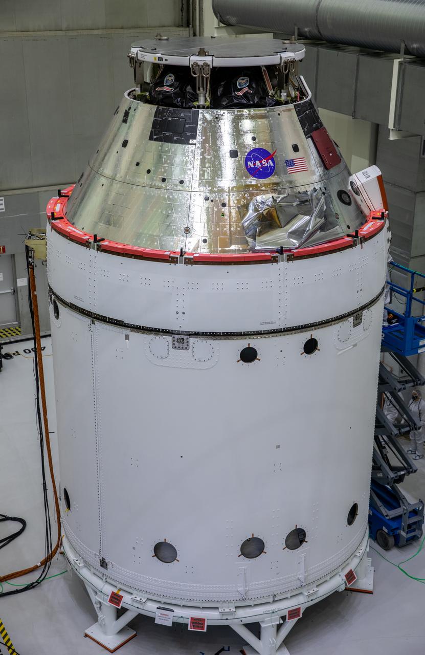
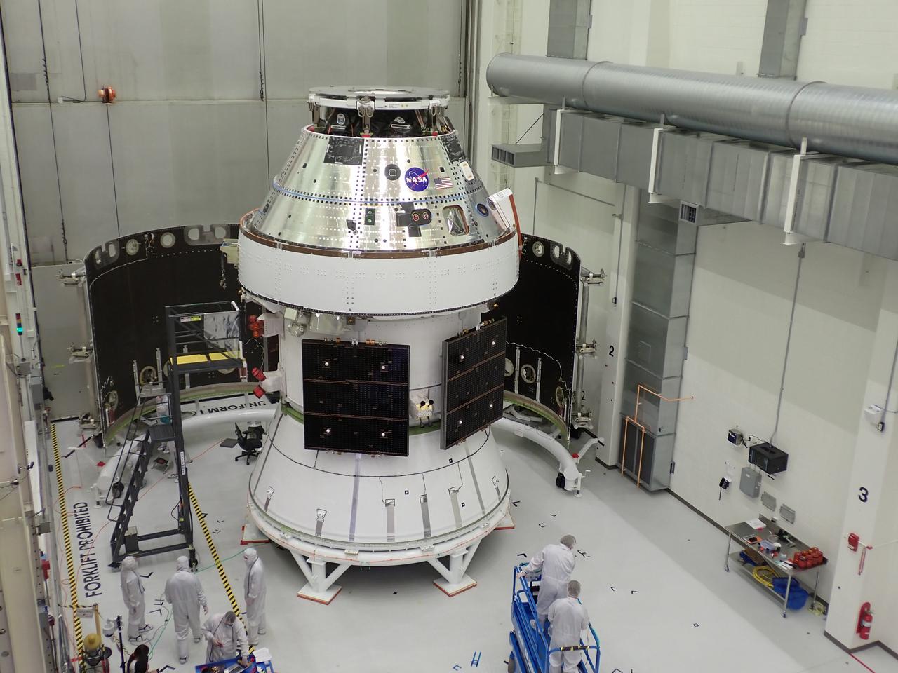
The Orion spacecraft for NASA’s Artemis I mission is in view inside the Neil Armstrong Operations and Checkout Building high bay on Oct. 28, 2020, at NASA’s Kennedy Space Center in Florida. The NASA insignia, also called the “meatball,” and the American Flag have been applied to the Orion crew module back shell. Attached below Orion are the crew module adapter and the European Service Module (ESM) with spacecraft adapter jettison fairings installed. Recently, teams from across the globe installed the four solar array wings, which are housed inside the protective covering of the fairings. The fairing panels will encapsulate the ESM to protect it from harsh environments such as heat, wind, and acoustics as the spacecraft is propelled out of Earth’s atmosphere atop the Space Launch System rocket during NASA’s Artemis I mission.
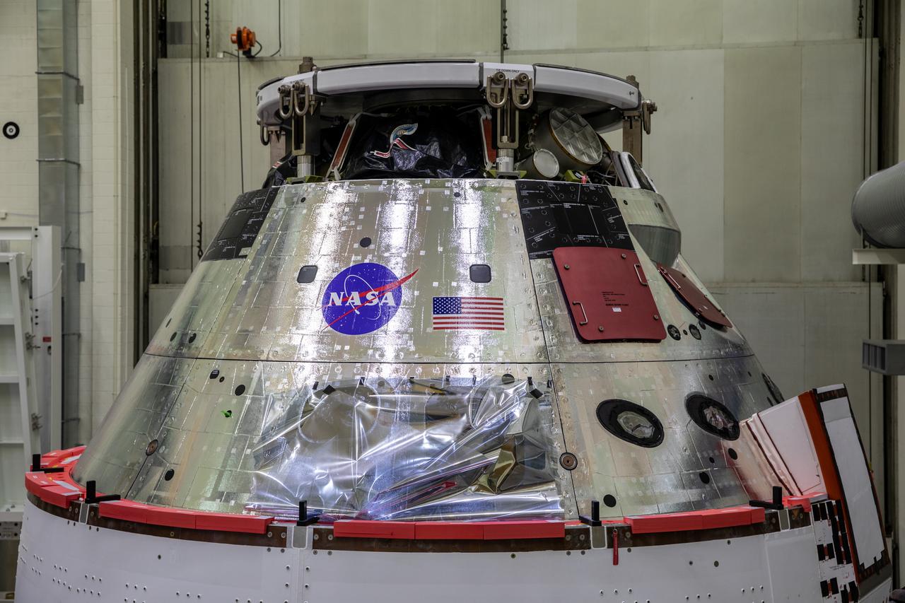
The NASA insignia, also called the “meatball,” and the American Flag are applied to the Orion crew module back shell for the Artemis I mission on Oct. 28, 2020, inside the Neil Armstrong Operations and Checkout Building at NASA’s Kennedy Space Center in Florida. Attached below Orion are the crew module adapter and the European Service Module (ESM) with spacecraft adapter jettison fairings installed. Recently, teams from across the globe installed the four solar array wings, which are housed inside the protective covering of the fairings. The fairing panels will encapsulate the ESM to protect it from harsh environments such as heat, wind, and acoustics as the spacecraft is propelled out of Earth’s atmosphere atop the Space Launch System rocket during NASA’s Artemis I mission.
The NASA insignia, also called the “meatball,” and the American Flag are applied to the Orion crew module back shell for the Artemis I mission on Oct. 28, 2020, inside the Neil Armstrong Operations and Checkout Building at NASA’s Kennedy Space Center in Florida. Attached below Orion are the crew module adapter and the European Service Module (ESM) with spacecraft adapter jettison fairings installed. Recently, teams from across the globe installed the four solar array wings, which are housed inside the protective covering of the fairings. The fairing panels will encapsulate the ESM to protect it from harsh environments such as heat, wind, and acoustics as the spacecraft is propelled out of Earth’s atmosphere atop the Space Launch System rocket during NASA’s Artemis I mission.

The NASA insignia, also called the “meatball,” and the American Flag are applied to the Orion crew module back shell for the Artemis I mission on Oct. 28, 2020, inside the Neil Armstrong Operations and Checkout Building at NASA’s Kennedy Space Center in Florida. Attached below Orion are the crew module adapter and the European Service Module (ESM) with spacecraft adapter jettison fairings installed. Recently, teams from across the globe installed the four solar array wings, which are housed inside the protective covering of the fairings. The fairing panels will encapsulate the ESM to protect it from harsh environments such as heat, wind, and acoustics as the spacecraft is propelled out of Earth’s atmosphere atop the Space Launch System rocket during NASA’s Artemis I mission.
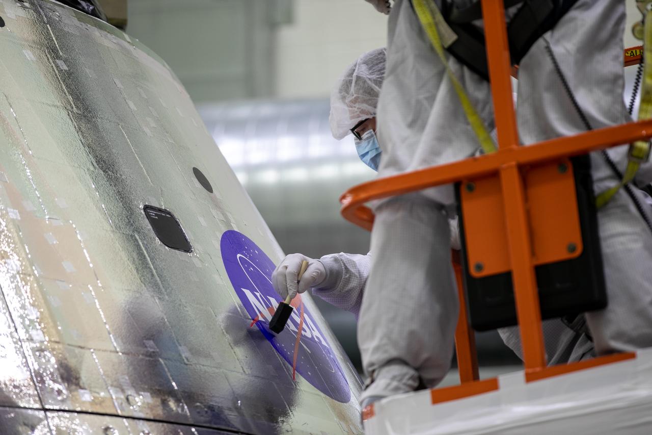
Frank Pelkey, ASRC technician, paints a clear adhesive over the NASA insignia, also called the “meatball,” on the Orion crew module back shell for the Artemis I mission on Oct. 28, 2020, inside the Neil Armstrong Operations and Checkout Building (O&C) at NASA’s Kennedy Space Center in Florida. The American Flag also has been added. Attached below Orion (not in view) are the crew module adapter and the European Service Module (ESM) with spacecraft adapter jettison fairings installed. Recently, teams from across the globe installed the four solar array wings, which are housed inside the protective covering of the fairings. The fairing panels will encapsulate the ESM to protect it from harsh environments such as heat, wind, and acoustics as the spacecraft is propelled out of Earth’s atmosphere atop the Space Launch System rocket during NASA’s Artemis I mission.
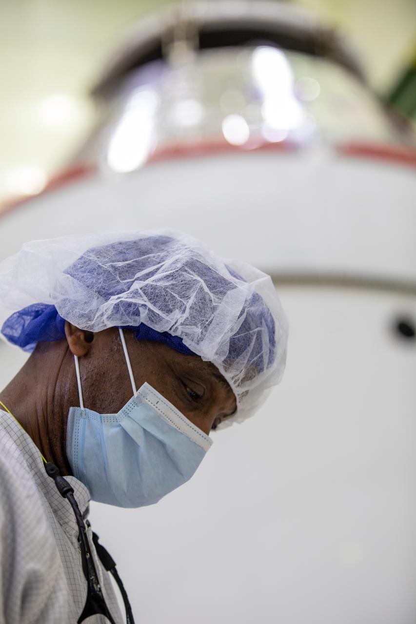
Izeal Battle, ASRC technician, is shown in the foreground with the Orion spacecraft for the Artemis I mission on Oct. 28, 2020, inside the Neil Armstrong Operations and Checkout Building (O&C) at NASA’s Kennedy Space Center in Florida. Attached below Orion (not in view) are the crew module adapter and the European Service Module (ESM) with spacecraft adapter jettison fairings installed. Recently, teams from across the globe installed the four solar array wings, which are housed inside the protective covering of the fairings. The fairing panels will encapsulate the ESM to protect it from harsh environments such as heat, wind, and acoustics as the spacecraft is propelled out of Earth’s atmosphere atop the Space Launch System rocket during NASA’s Artemis I mission.

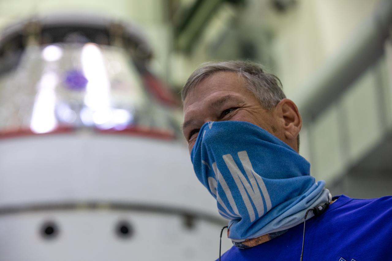
Shawn Corwin, at left, ASRC technician, Shawn Corwin, at left, points to the Orion spacecraft for the Artemis I mission inside the Neil Armstrong Operations and Checkout Building at NASA’s Kennedy Space Center in Florida on Oct. 28, 2020. At right is Eric Nolan, ASRC technician. The NASA insignia, also called the “meatball,” and American Flag have been applied to the Orion crew module back shell. Attached below Orion are the crew module adapter and the European Service Module (ESM) with spacecraft adapter jettison fairings installed. Recently, teams from across the globe installed the four solar array wings, which are housed inside the protective covering of the fairings. The fairing panels will encapsulate the ESM to protect it from harsh environments such as heat, wind, and acoustics as the spacecraft is propelled out of Earth’s atmosphere atop the Space Launch System rocket during NASA’s Artemis I mission.
Todd Biddle, ASRC technician, is shown in the foreground with the Orion spacecraft for the Artemis I mission behind him inside the Neil Armstrong Operations and Checkout Building at NASA’s Kennedy Space Center in Florida on Oct. 28, 2020. The NASA insignia, also called the “meatball,” and American Fag have been applied to the Orion crew module back shell. Attached below Orion are the crew module adapter and the European Service Module (ESM) with spacecraft adapter jettison fairings installed. Recently, teams from across the globe installed the four solar array wings, which are housed inside the protective covering of the fairings. The fairing panels will encapsulate the ESM to protect it from harsh environments such as heat, wind, and acoustics as the spacecraft is propelled out of Earth’s atmosphere atop the Space Launch System rocket during NASA’s Artemis I mission.
The NASA insignia, also called the “meatball,” and the American Flag are applied to the Orion crew module back shell for the Artemis I mission on Oct. 28, 2020, inside the Neil Armstrong Operations and Checkout Building at NASA’s Kennedy Space Center in Florida. Attached below Orion are the crew module adapter and the European Service Module (ESM) with spacecraft adapter jettison fairings installed. Recently, teams from across the globe installed the four solar array wings, which are housed inside the protective covering of the fairings. The fairing panels will encapsulate the ESM to protect it from harsh environments such as heat, wind, and acoustics as the spacecraft is propelled out of Earth’s atmosphere atop the Space Launch System rocket during NASA’s Artemis I mission.

S66-54590 (13 Sept. 1966) --- Astronaut Richard F. Gordon Jr., Gemini-11 pilot, prepares to open spacecraft hatch to jettison used equipment. Photo credit: NASA
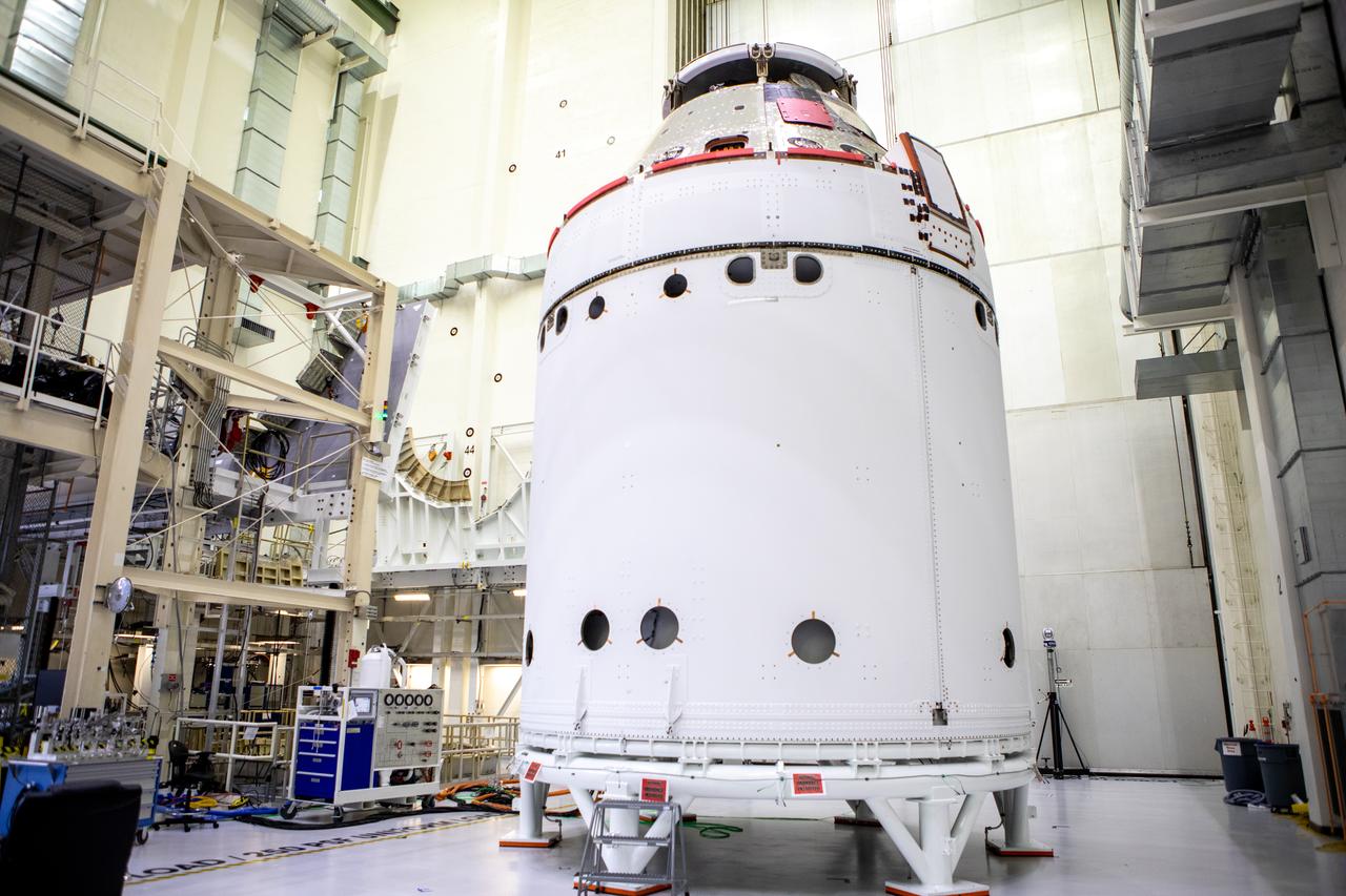
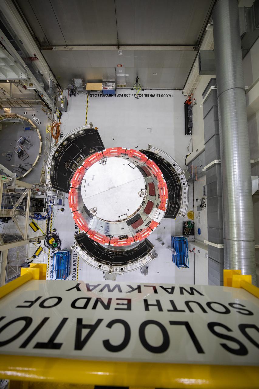
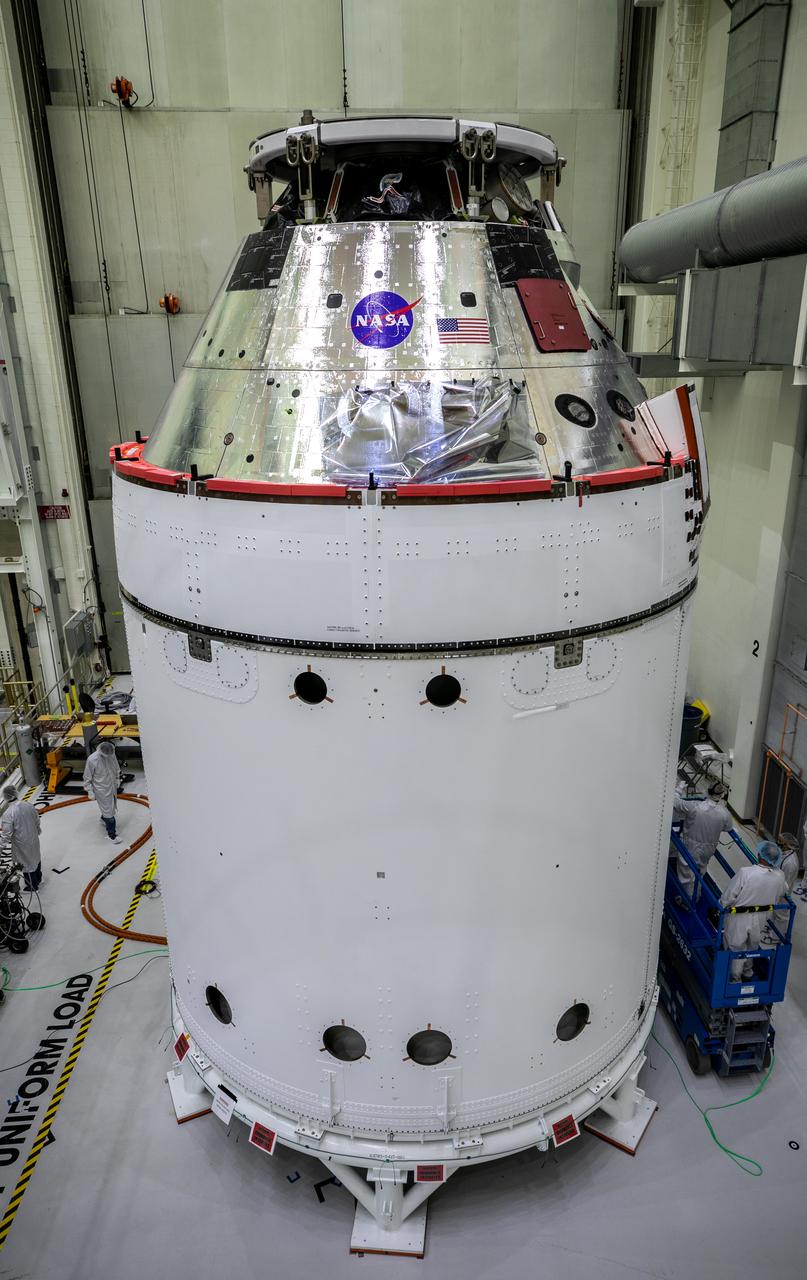
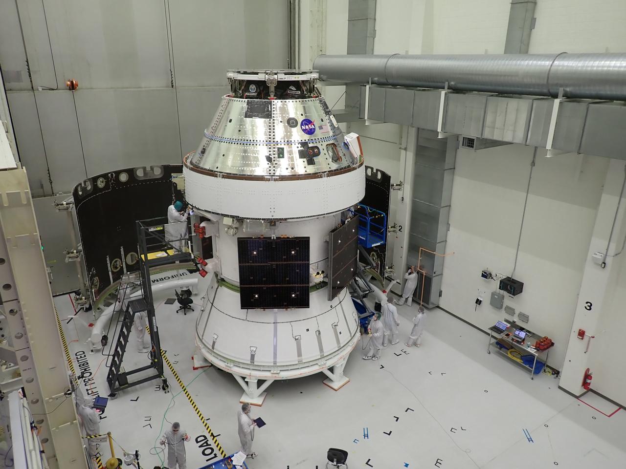
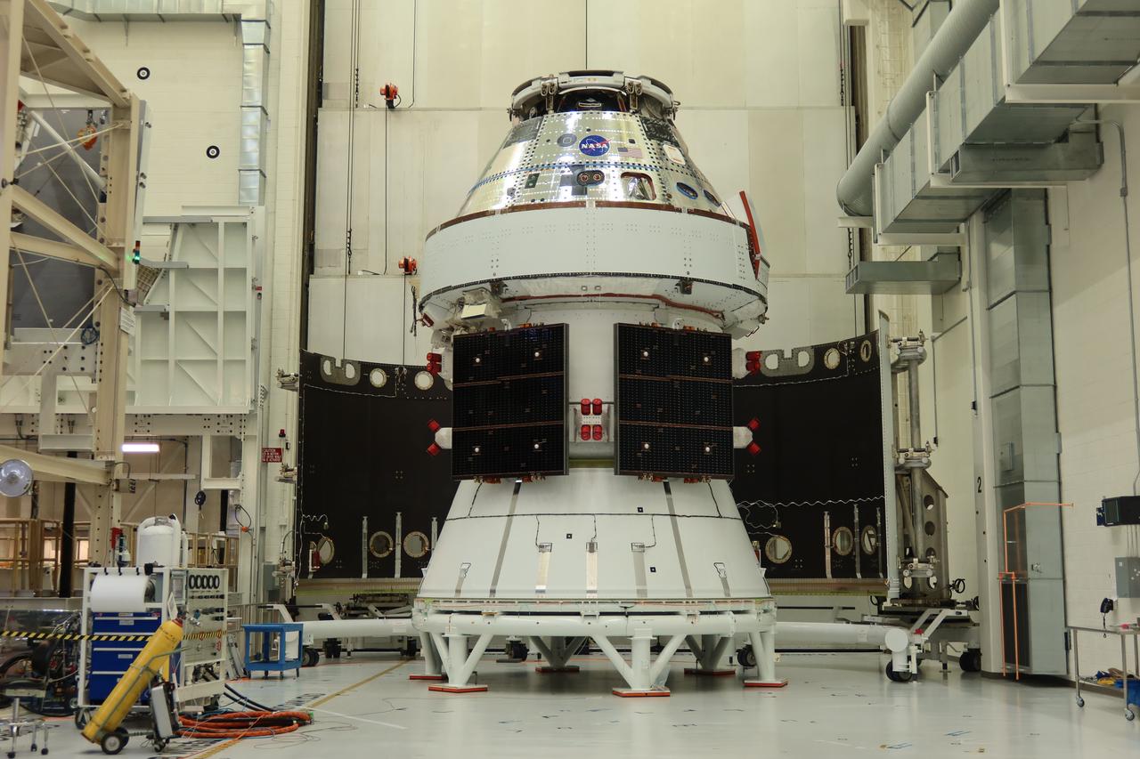
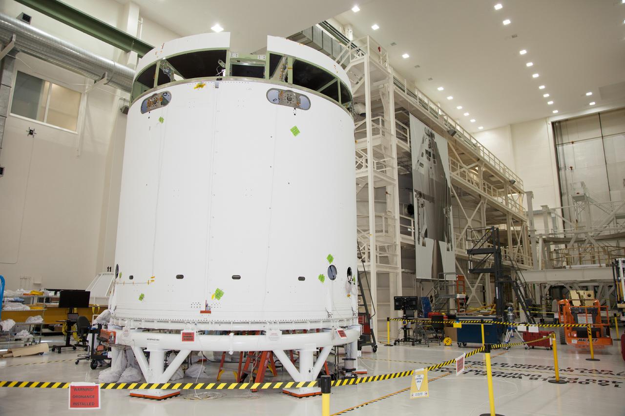
The Artemis II Orion spacecraft sits in the transfer aisle in the Neil A. Armstrong Operations and Checkout Building at NASA’s Kennedy Space Center in Florida following successful installation of three spacecraft adapter jettison fairings on Wednesday, March 19, 2025. The fairings encapsulate the service module and protect the solar array wings, shielding them from the heat, wind, and acoustics of launch and ascent, as well as help redistribute the load between Orion and the massive thrust of the SLS (Space Launch System) rocket during liftoff and ascent. Once the spacecraft is above the atmosphere, the three fairing panels will separate from the service module reducing the mass of the spacecraft.
The Artemis II Orion spacecraft sits in the transfer aisle in the Neil A. Armstrong Operations and Checkout Building at NASA’s Kennedy Space Center in Florida following successful installation of three spacecraft adapter jettison fairings on Wednesday, March 19, 2025. The fairings encapsulate the service module and protect the solar array wings, shielding them from the heat, wind, and acoustics of launch and ascent, as well as help redistribute the load between Orion and the massive thrust of the SLS (Space Launch System) rocket during liftoff and ascent. Once the spacecraft is above the atmosphere, the three fairing panels will separate from the service module reducing the mass of the spacecraft.
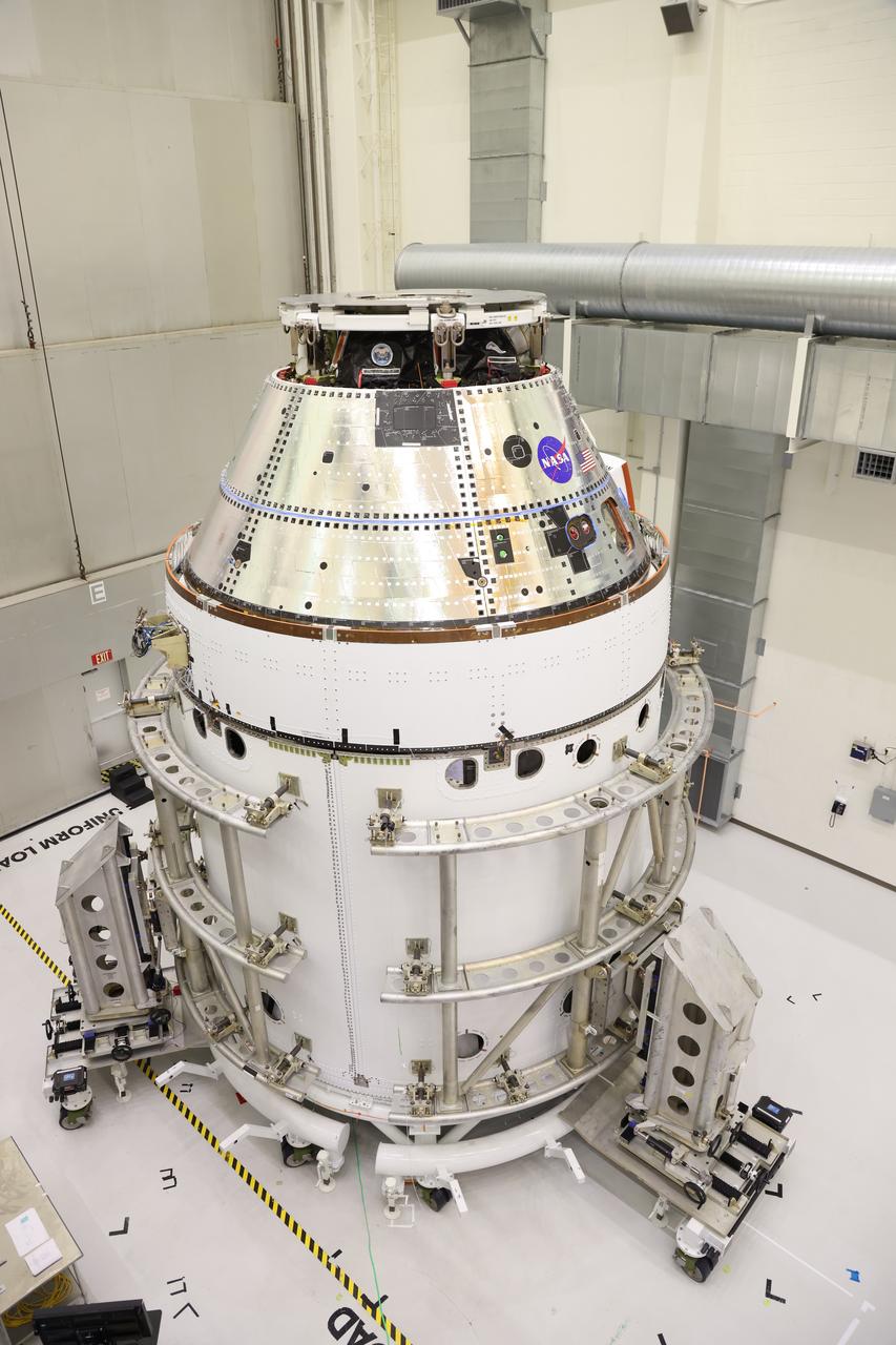
The Artemis II Orion spacecraft sits in the transfer aisle in the Neil A. Armstrong Operations and Checkout Building at NASA’s Kennedy Space Center in Florida following successful installation of three spacecraft adapter jettison fairings on Wednesday, March 19, 2025. The fairings encapsulate the service module and protect the solar array wings, shielding them from the heat, wind, and acoustics of launch and ascent, as well as help redistribute the load between Orion and the massive thrust of the SLS (Space Launch System) rocket during liftoff and ascent. Once the spacecraft is above the atmosphere, the three fairing panels will separate from the service module reducing the mass of the spacecraft.
STS057-03-017 (21 June 1993) --- The external fuel tank falls toward Earth after being jettisoned from the Space Shuttle Endeavour as the spacecraft headed toward its ten-day stay in Earth orbit. A 35mm camera was used to record the ET jettison.
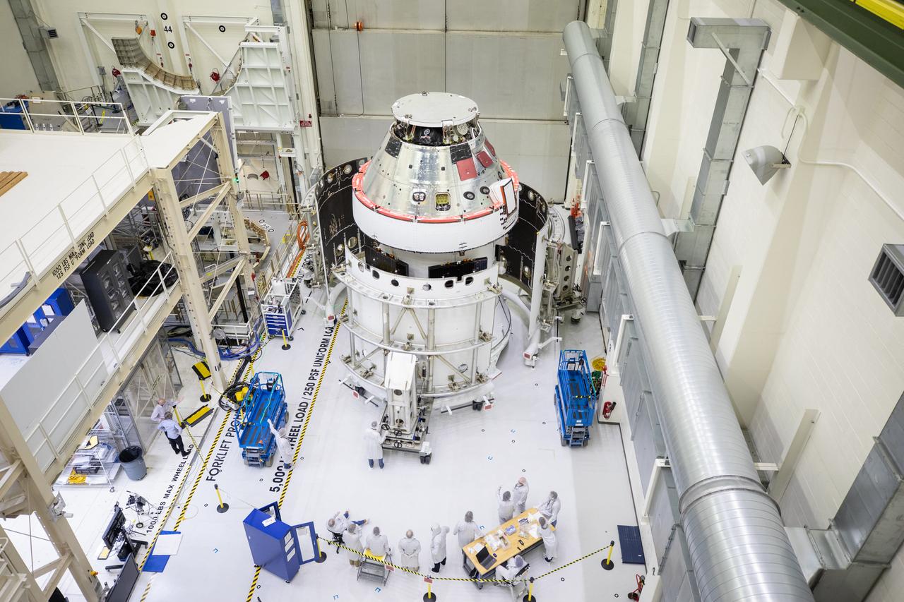
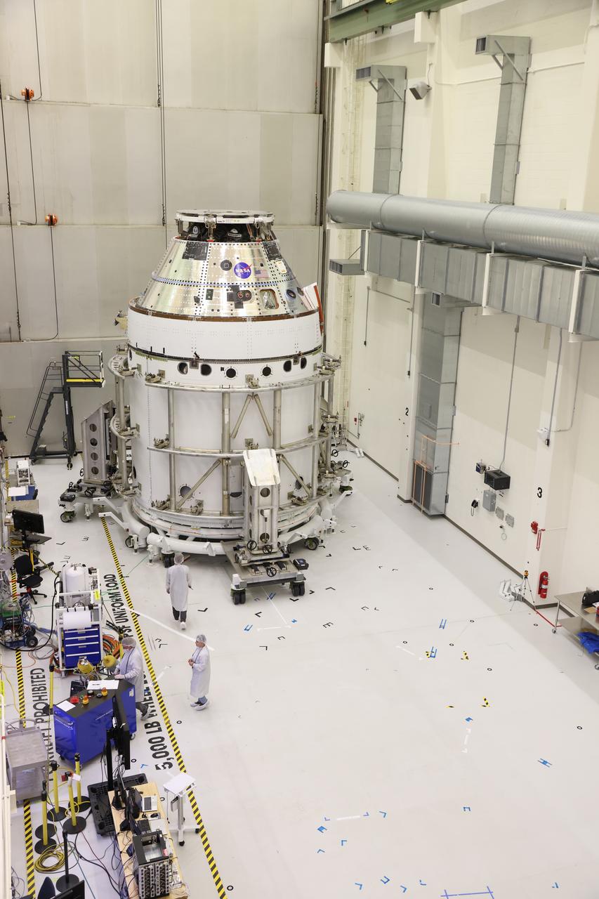
Technicians with Lockheed Martin prepare the Artemis II Orion spacecraft for the installation of three spacecraft adapter jettison fairings inside the Neil A. Armstrong Operations and Checkout Building at NASA’s Kennedy Space Center in Florida in on Tuesday, March 11, 2025. The fairings encapsulate the service module and protect the solar array wings, shielding them from the heat, wind, and acoustics of launch and ascent, plus help redistribute the load between Orion and the massive thrust of the SLS (Space Launch System) rocket during liftoff and ascent. Once the spacecraft is above the atmosphere, the three fairing panels will separate from the service module reducing the mass of the spacecraft.
Technicians with Lockheed Martin prepare the Artemis II Orion spacecraft for the installation of three spacecraft adapter jettison fairings inside the Neil A. Armstrong Operations and Checkout Building at NASA’s Kennedy Space Center in Florida in on Tuesday, March 11, 2025. The fairings encapsulate the service module and protect the solar array wings, shielding them from the heat, wind, and acoustics of launch and ascent, plus help redistribute the load between Orion and the massive thrust of the SLS (Space Launch System) rocket during liftoff and ascent. Once the spacecraft is above the atmosphere, the three fairing panels will separate from the service module reducing the mass of the spacecraft.
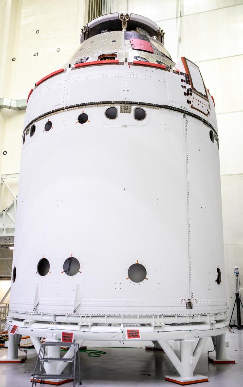
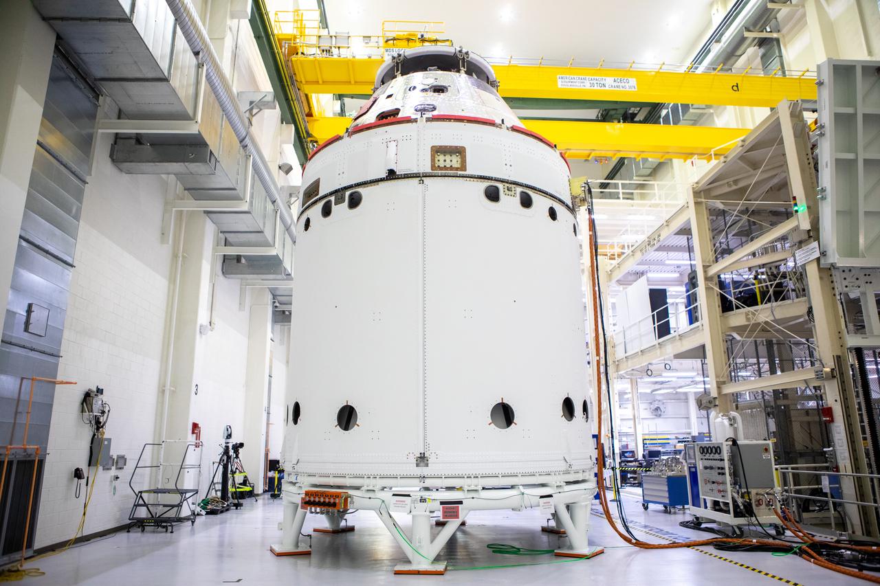
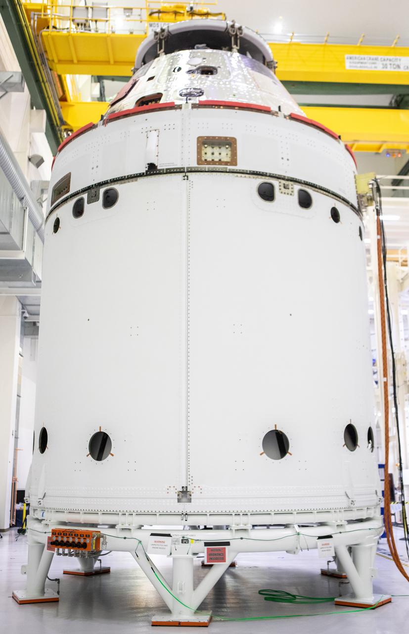
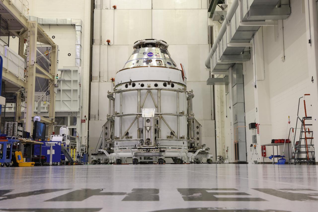
The Artemis II Orion spacecraft sits in the transfer aisle in the Neil A. Armstrong Operations and Checkout Building at NASA’s Kennedy Space Center in Florida in preparation for the installation of three spacecraft adapter jettison fairings on Tuesday, March 11, 2025. The fairings encapsulate the service module and protect the solar array wings, shielding them from the heat, wind, and acoustics of launch and ascent, plus help redistribute the load between Orion and the massive thrust of the SLS (Space Launch System) rocket during liftoff and ascent. Once the spacecraft is above the atmosphere, the three fairing panels will separate from the service module reducing the mass of the spacecraft.
Technicians with Lockheed Martin prepare the Artemis II Orion spacecraft for the installation of three spacecraft adapter jettison fairings inside the Neil A. Armstrong Operations and Checkout Building at NASA’s Kennedy Space Center in Florida in on Tuesday, March 11, 2025. The fairings encapsulate the service module and protect the solar array wings, shielding them from the heat, wind, and acoustics of launch and ascent, plus help redistribute the load between Orion and the massive thrust of the SLS (Space Launch System) rocket during liftoff and ascent. Once the spacecraft is above the atmosphere, the three fairing panels will separate from the service module reducing the mass of the spacecraft.
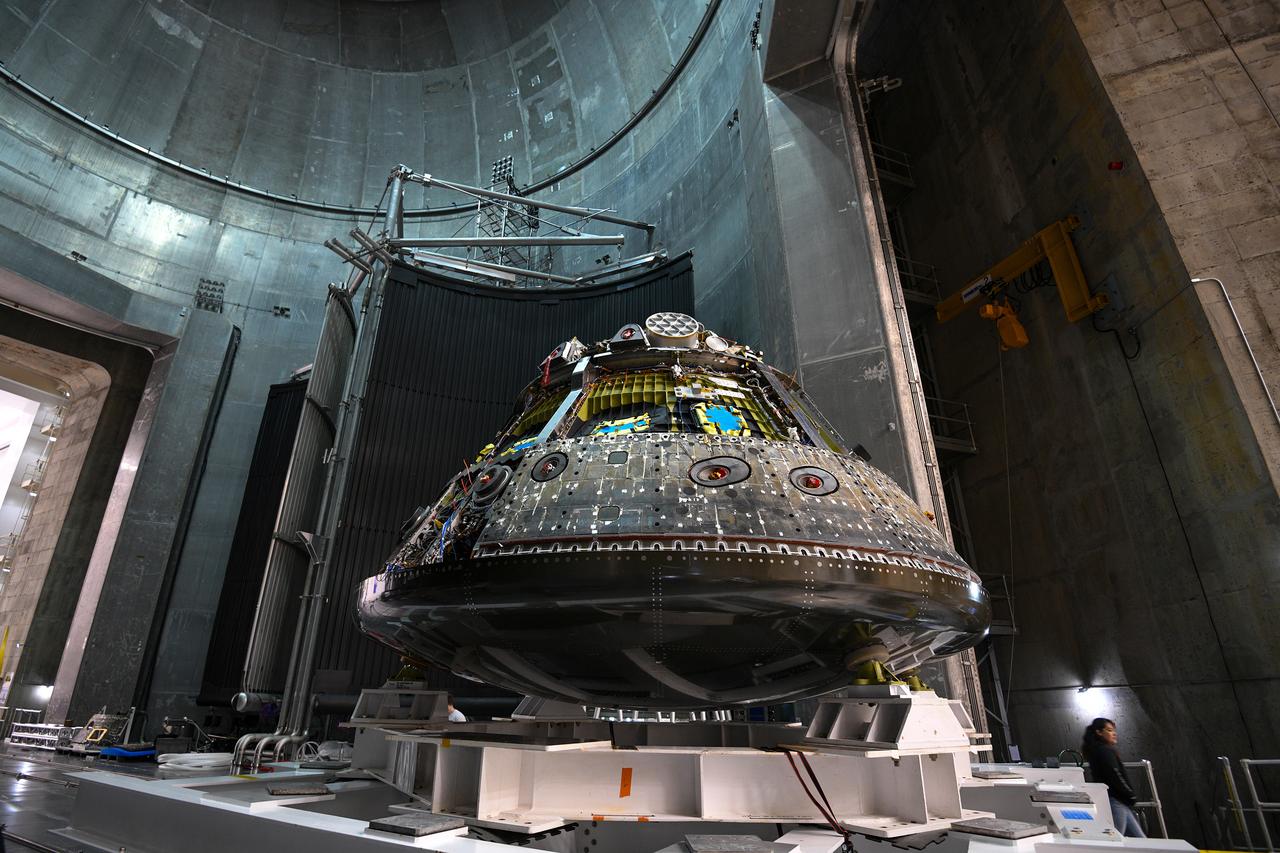
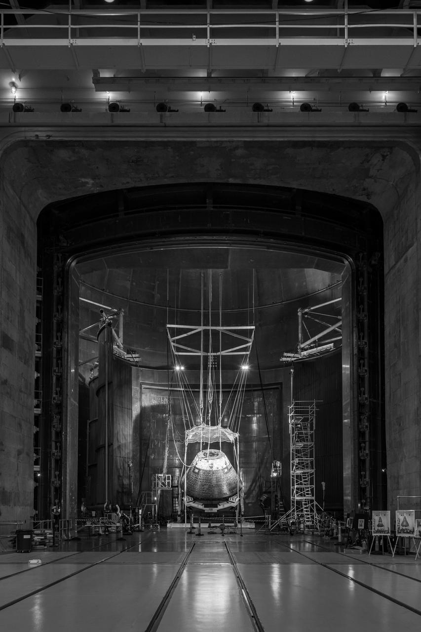
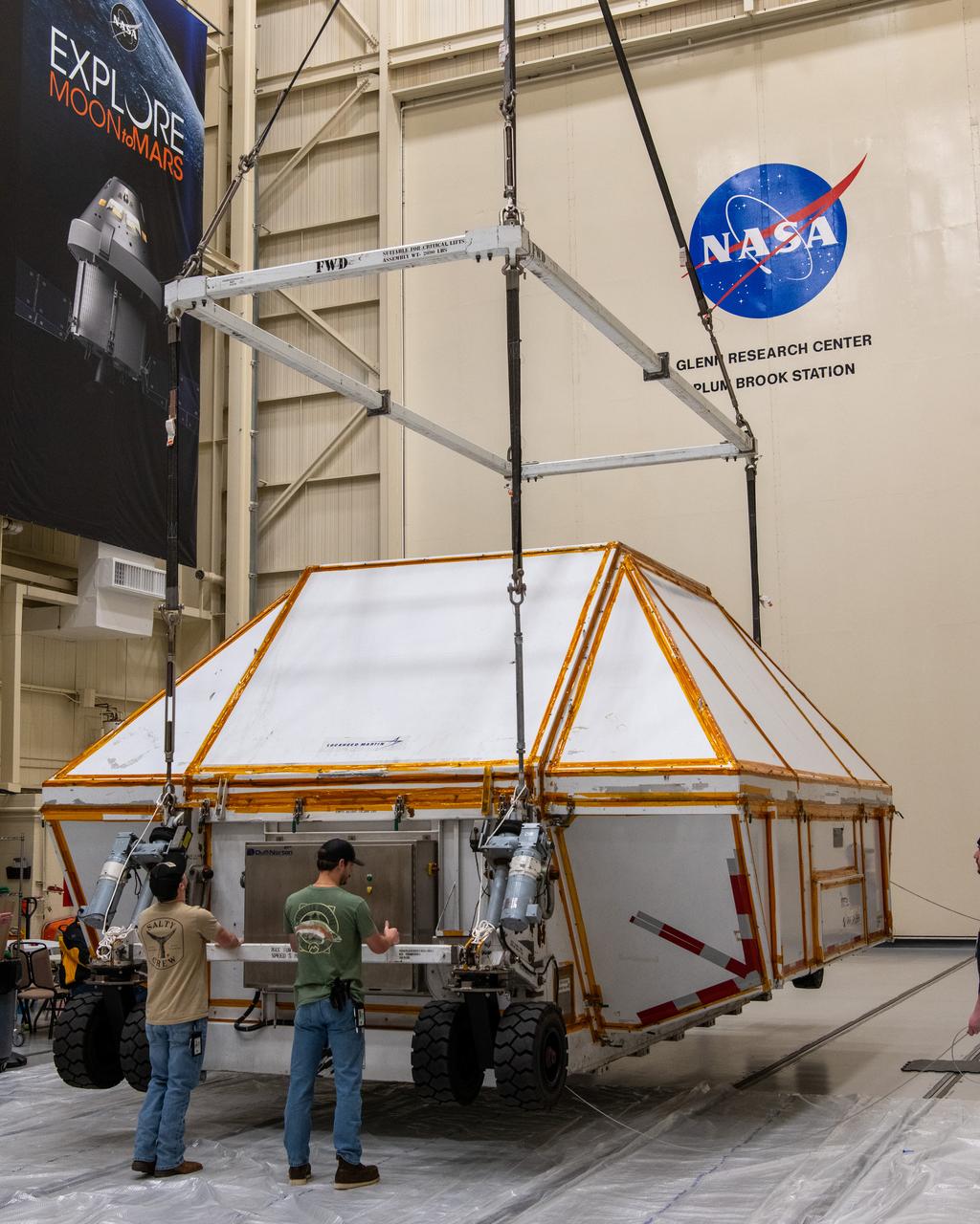
The Orion CM (Crew Module) or Orion ETA (Environmental Test Article) is passed through the vacuum chamber on its way to get ready for two critical tests in preparation for the Artemis II flight. There will be a jettison test of the Docking Module and a jettison test of the Forward Bay Cover.
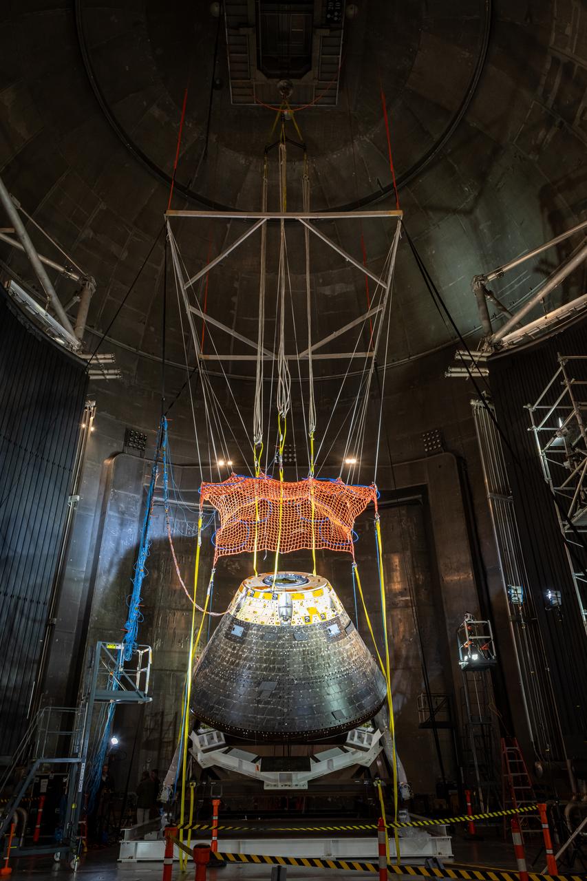
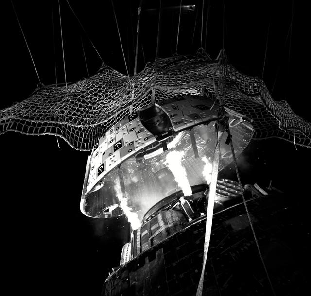
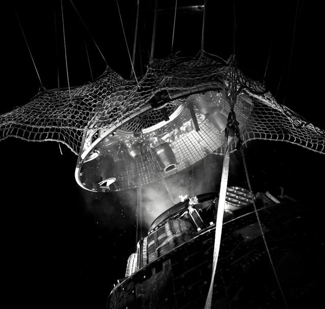
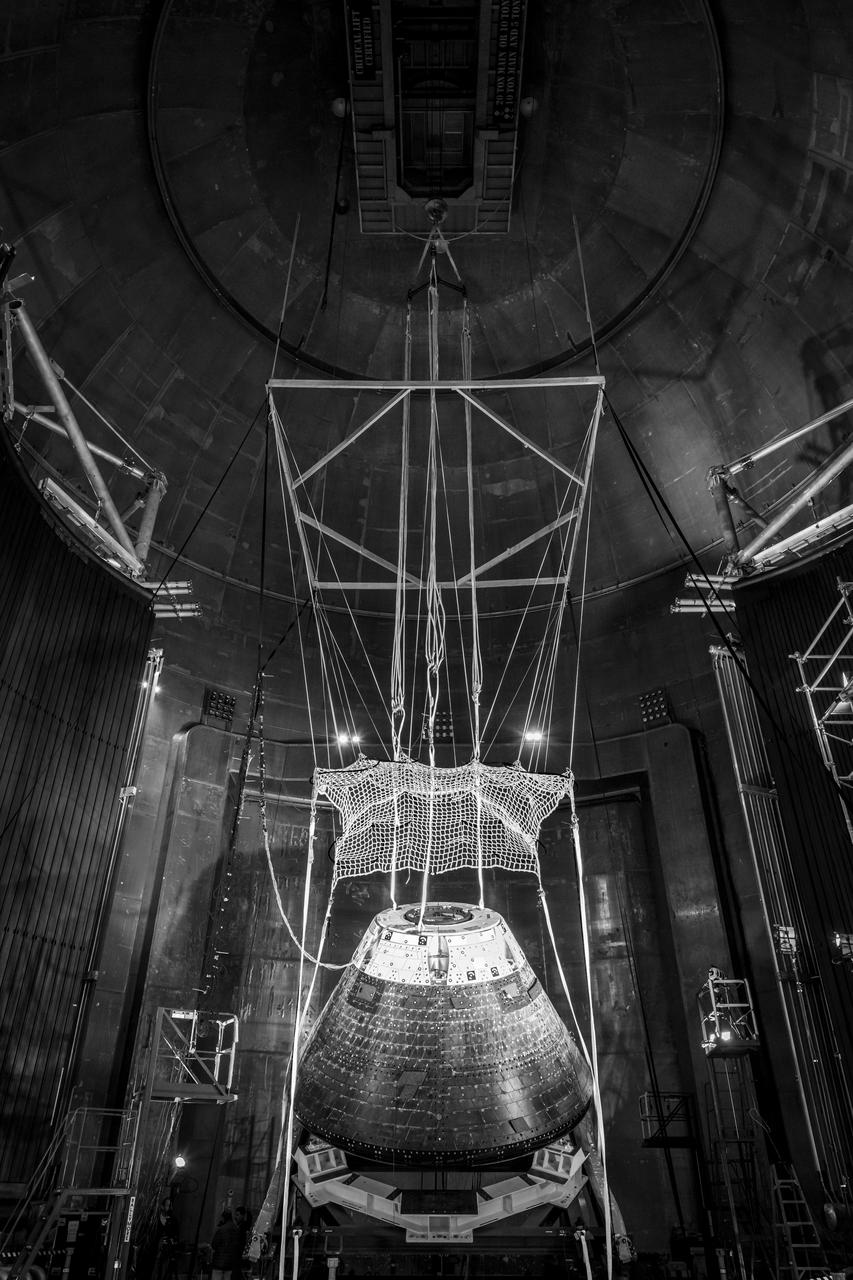
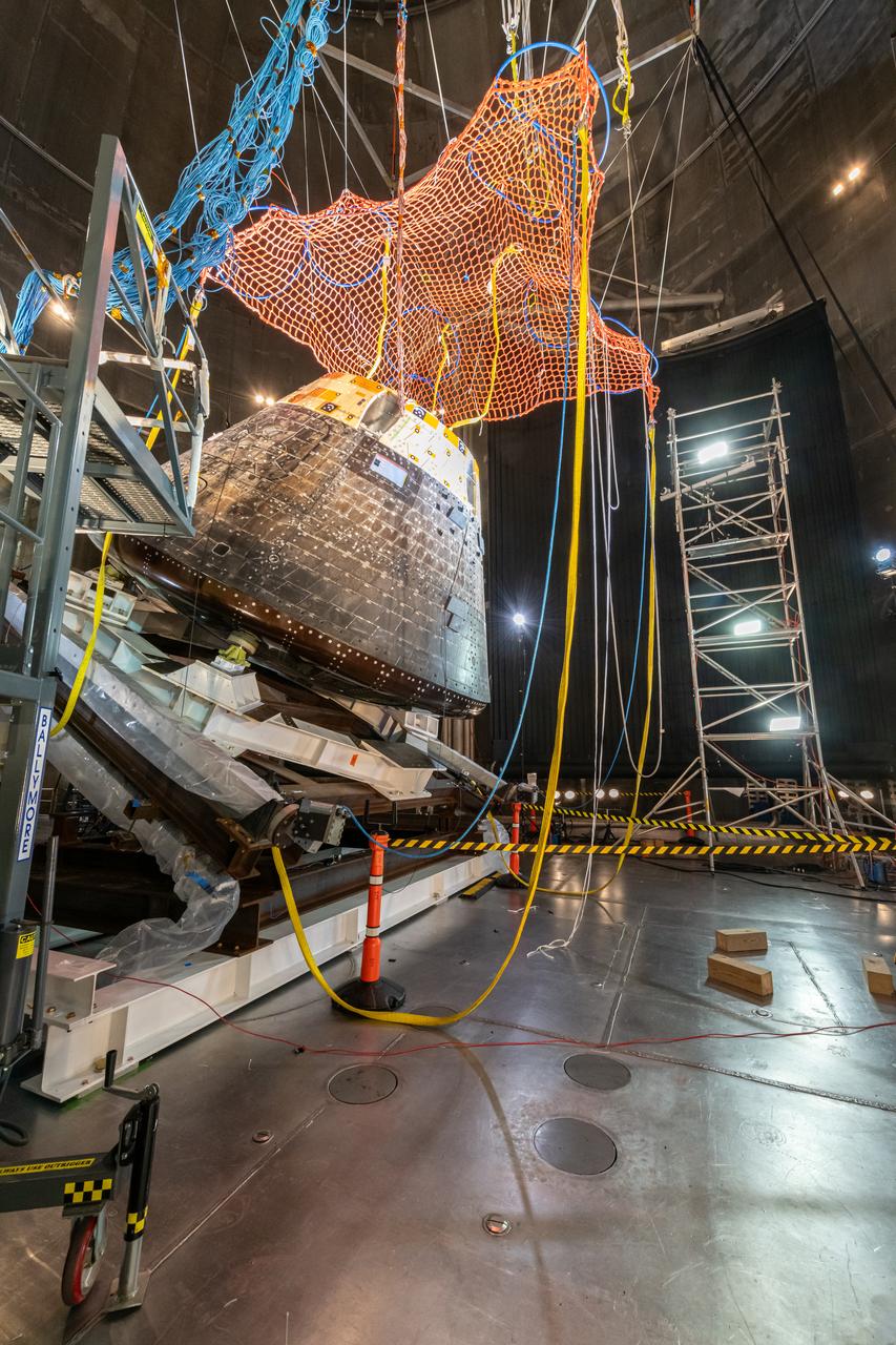
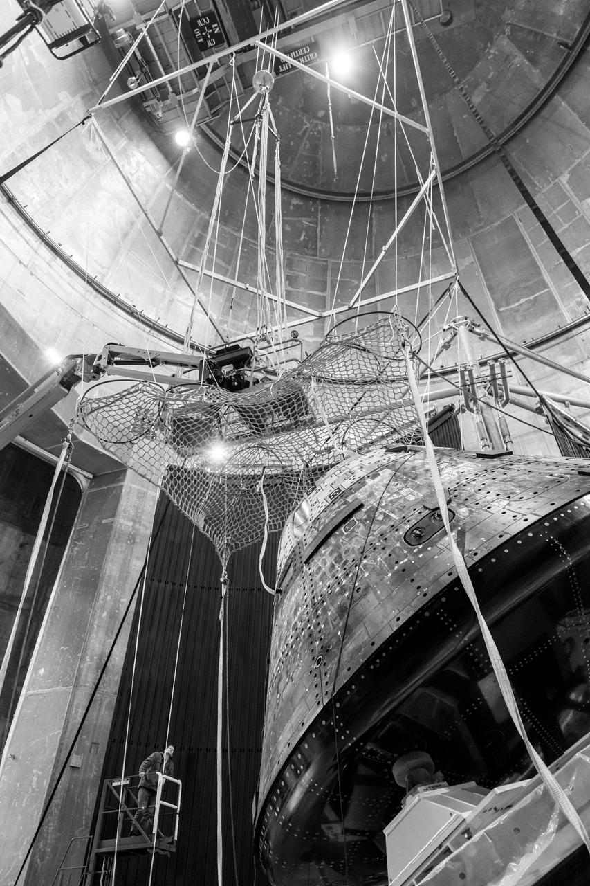
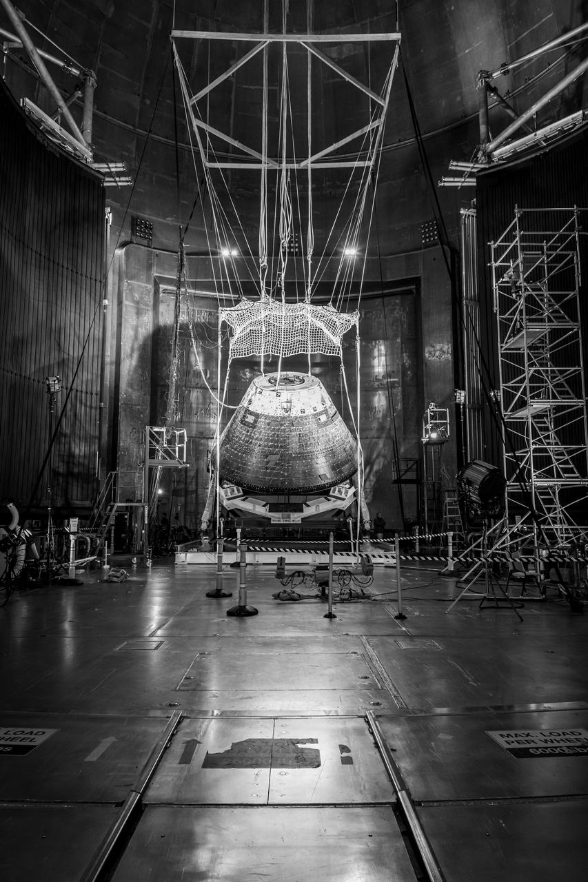
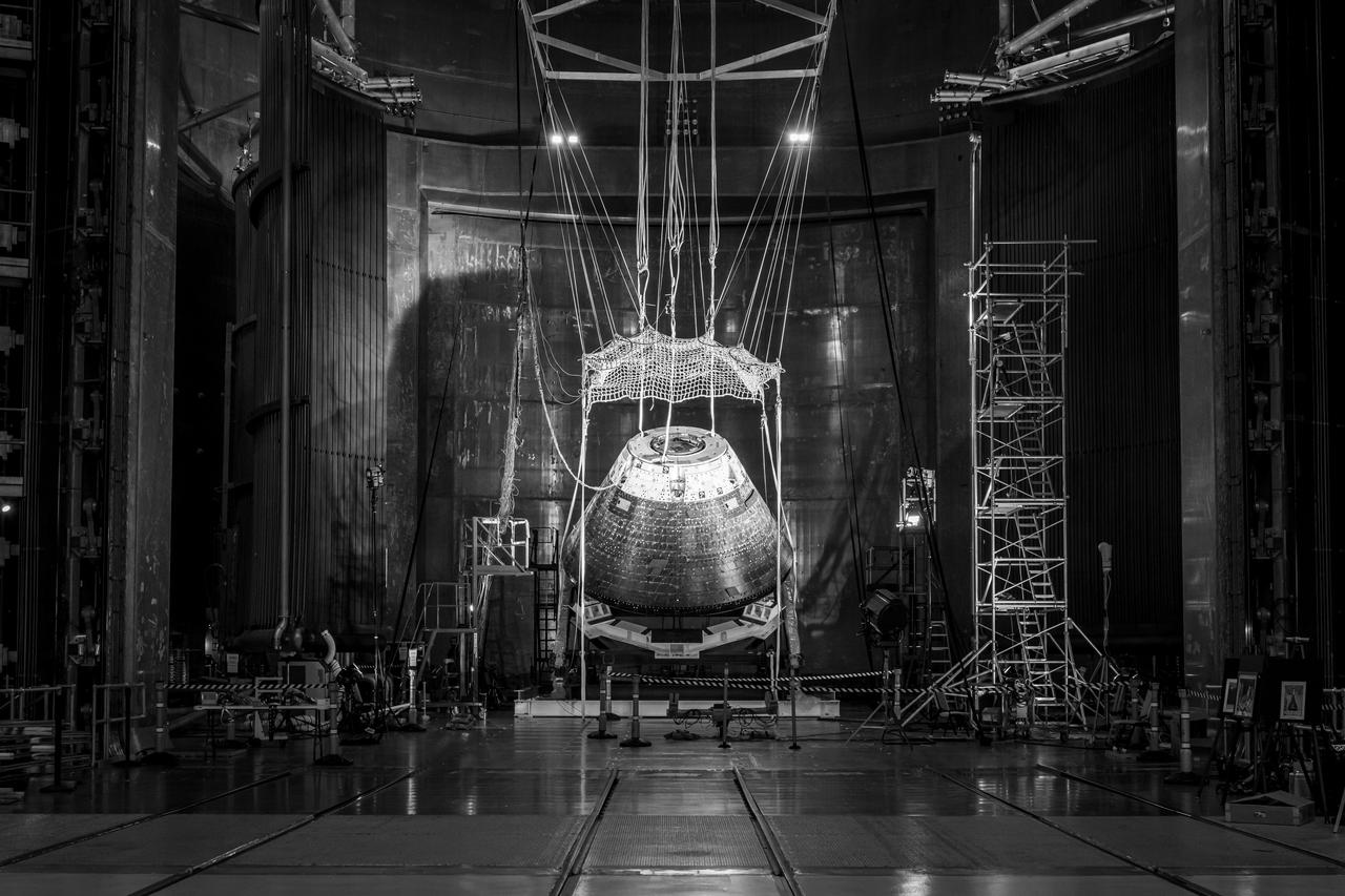
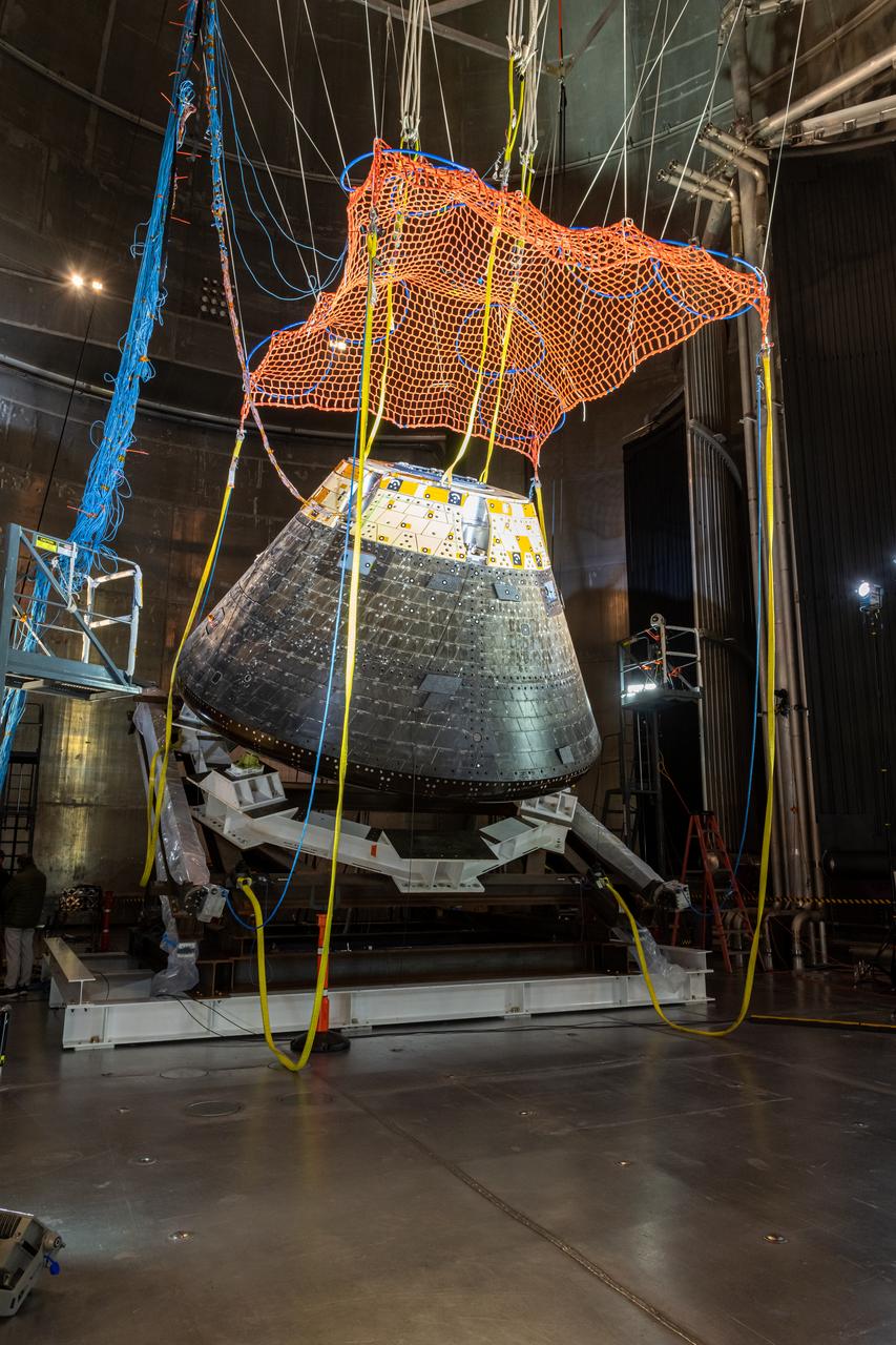
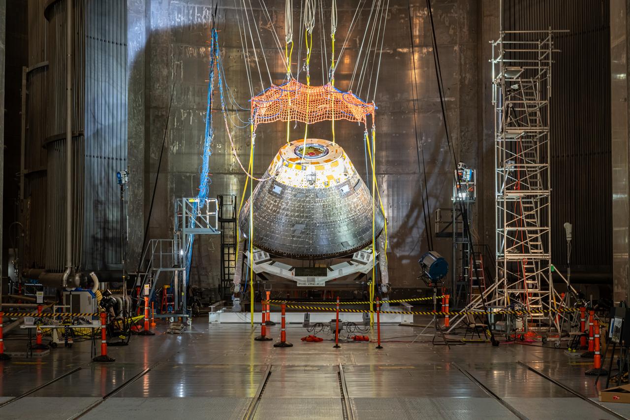
The Orion Crew Module, also known as the Orion Environmental Test Article (ETA), returned to NASA’s Neil Armstrong Test Facility in Sandusky, Ohio, in January 2024 and completed an 11-month test campaign necessary for the safety and success of Artemis II. In November 2024, experts completed the Forward Bay Cover jettison test, which is the last piece that must eject right before parachutes deploy. This image shows the setup right before the FBC deployment test. Photo Credit: (NASA/Jordan Salkin)
The Orion Crew Module, also known as the Orion Environmental Test Article (ETA), returned to NASA’s Neil Armstrong Test Facility in Sandusky, Ohio, in January 2024 and completed an 11-month test campaign necessary for the safety and success of Artemis II. In November 2024, experts completed the Forward Bay Cover jettison test, which is the last piece that must eject right before parachutes deploy. Photo Credit: (NASA/Quentin Schwinn and Jordan Salkin)
The Orion Crew Module, also known as the Orion Environmental Test Article (ETA), returned to NASA’s Neil Armstrong Test Facility in Sandusky, Ohio, in January 2024 and completed an 11-month test campaign necessary for the safety and success of Artemis II. In November 2024, experts completed the Forward Bay Cover jettison test, which is the last piece that must eject right before parachutes deploy.
The Orion Crew Module, also known as the Orion Environmental Test Article (ETA), returned to NASA’s Neil Armstrong Test Facility in Sandusky, Ohio, in January 2024 and completed an 11-month test campaign necessary for the safety and success of Artemis II. In November 2024, experts completed the Forward Bay Cover jettison test, which is the last piece that must eject right before parachutes deploy. This image shows the setup right before the FBC deployment test. Photo Credit: (NASA/Jordan Salkin)
The Orion Crew Module, also known as the Orion Environmental Test Article (ETA), returned to NASA’s Neil Armstrong Test Facility in Sandusky, Ohio, in January 2024 and completed an 11-month test campaign necessary for the safety and success of Artemis II. In November 2024, experts completed the Forward Bay Cover jettison test, which is the last piece that must eject right before parachutes deploy. This image shows the setup right before the FBC deployment test. Photo Credit: (NASA/Jordan Salkin)
The Orion Crew Module, also known as the Orion Environmental Test Article (ETA), returned to NASA’s Neil Armstrong Test Facility in Sandusky, Ohio, in January 2024 and completed an 11-month test campaign necessary for the safety and success of Artemis II. In November 2024, experts completed the Forward Bay Cover jettison test, which is the last piece that must eject right before parachutes deploy. This image shows the setup right before the FBC deployment test. Photo Credit: (NASA/Jordan Salkin)
The Orion Crew Module, also known as the Orion Environmental Test Article (ETA), returned to NASA’s Neil Armstrong Test Facility in Sandusky, Ohio, in January 2024 and completed an 11-month test campaign necessary for the safety and success of Artemis II. In November 2024, experts completed the Forward Bay Cover jettison test, which is the last piece that must eject right before parachutes deploy. This image shows the setup right before the FBC deployment test. Photo Credit: (NASA/Jordan Salkin)

The Orion Crew Module, also known as the Orion Environmental Test Article (ETA), returned to NASA’s Neil Armstrong Test Facility in Sandusky, Ohio, in January 2024 and completed an 11-month test campaign necessary for the safety and success of Artemis II. In November 2024, experts completed the Forward Bay Cover jettison test, which is the last piece that must eject right before parachutes deploy. This image shows the setup right before the FBC deployment test. Photo Credit: (NASA/Jordan Salkin)
The Orion Crew Module, also known as the Orion Environmental Test Article (ETA), returned to NASA’s Neil Armstrong Test Facility in Sandusky, Ohio, in January 2024 and completed an 11-month test campaign necessary for the safety and success of Artemis II. In November 2024, experts completed the Forward Bay Cover jettison test, which is the last piece that must eject right before parachutes deploy. This image shows the setup right before the FBC deployment test. Photo Credit: (NASA/Jordan Salkin)
The Orion Crew Module, also known as the Orion Environmental Test Article (ETA), returned to NASA’s Neil Armstrong Test Facility in Sandusky, Ohio, in January 2024 and completed an 11-month test campaign necessary for the safety and success of Artemis II. In November 2024, experts completed the Forward Bay Cover jettison test, which is the last piece that must eject right before parachutes deploy. This image shows the setup right before the FBC deployment test. Photo Credit: (NASA/Jordan Salkin)
The Orion Crew Module, also known as the Orion Environmental Test Article (ETA), returned to NASA’s Neil Armstrong Test Facility in Sandusky, Ohio, in January 2024 and completed an 11-month test campaign necessary for the safety and success of Artemis II. In November 2024, experts completed the Forward Bay Cover jettison test, which is the last piece that must eject right before parachutes deploy. This image shows the setup right before the FBC deployment test. Photo Credit: (NASA/Jordan Salkin)
The Orion Crew Module, also known as the Orion Environmental Test Article (ETA), returned to NASA’s Neil Armstrong Test Facility in Sandusky, Ohio, in January 2024 and completed an 11-month test campaign necessary for the safety and success of Artemis II. In November 2024, experts completed the Forward Bay Cover jettison test, which is the last piece that must eject right before parachutes deploy. This image shows the setup right before the FBC deployment test. Photo Credit: (NASA/Jordan Salkin)
Seven minutes before NASA Phoenix Mars Lander enters the Martian atmosphere, it will jettison the cruise stage hardware that it relied on during the long flight from Earth.
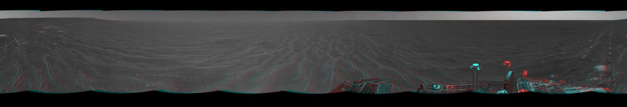
NASA Mars Exploration Rover Opportunity was on its way from Endurance Crater toward the spacecraft jettisoned heat shield in this anaglyph. 3D glasses are necessary to view this image.
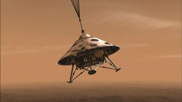
During the first 25 seconds after NASA Phoenix Mars Lander deploys its parachute, the spacecraft will jettison its heat shield and extend its three legs.
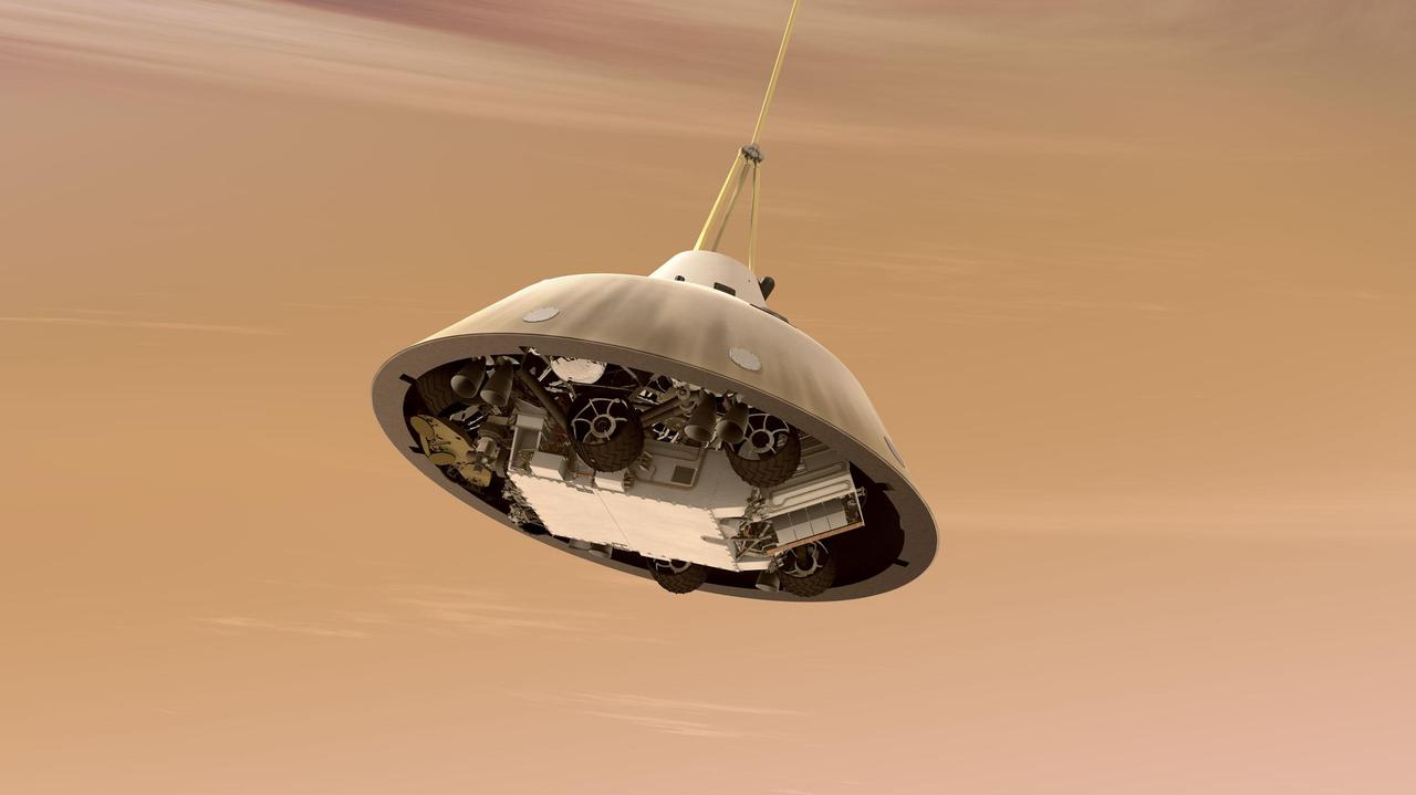
This artist concept shows NASA Curiosity rover tucked inside the Mars Science Laboratory spacecraft backshell while the spacecraft is descending on a parachute toward Mars. Here, the spacecraft heat shield has already been jettisoned.
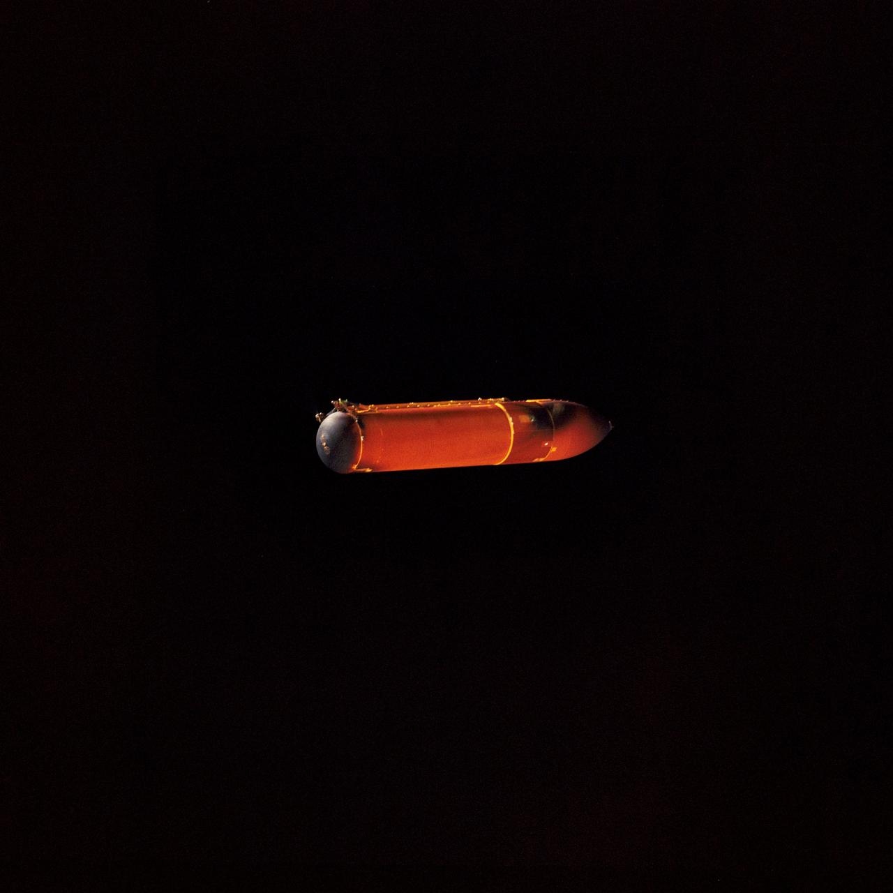
STS045-71-001 (24 March 1992) --- This 70mm photograph of the external fuel tank (ET) for STS-45 was photographed 4 1/2 minutes after having been jettisoned from Space Shuttle Atlantis. The excellent view of the starboard side of the ET shows both top and bottom attach points to the two solid rocket boosters (SRB). NASA engineers studying the STS-45 onboard photography deem the visible burn scars, caused by the SRBs, to be normal. The long thin pipe visible is the liquid oxygen line. At the bottom end of the large tank, both the liquid oxygen (nearest camera) and liquid hydrogen orbiter-to-ET attach hardware can be seen.
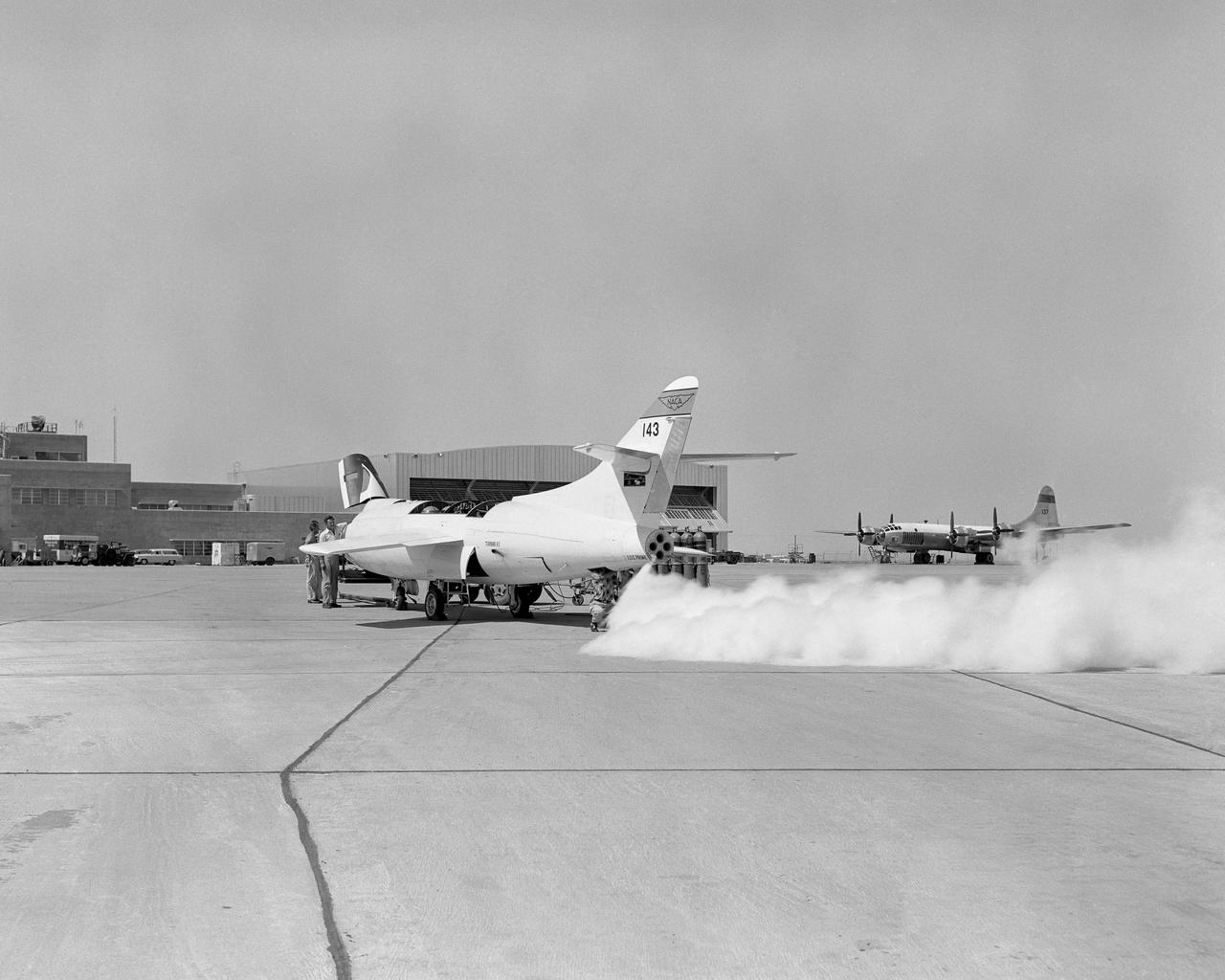
D558-2 #143 LOX jettison with P2BS in background
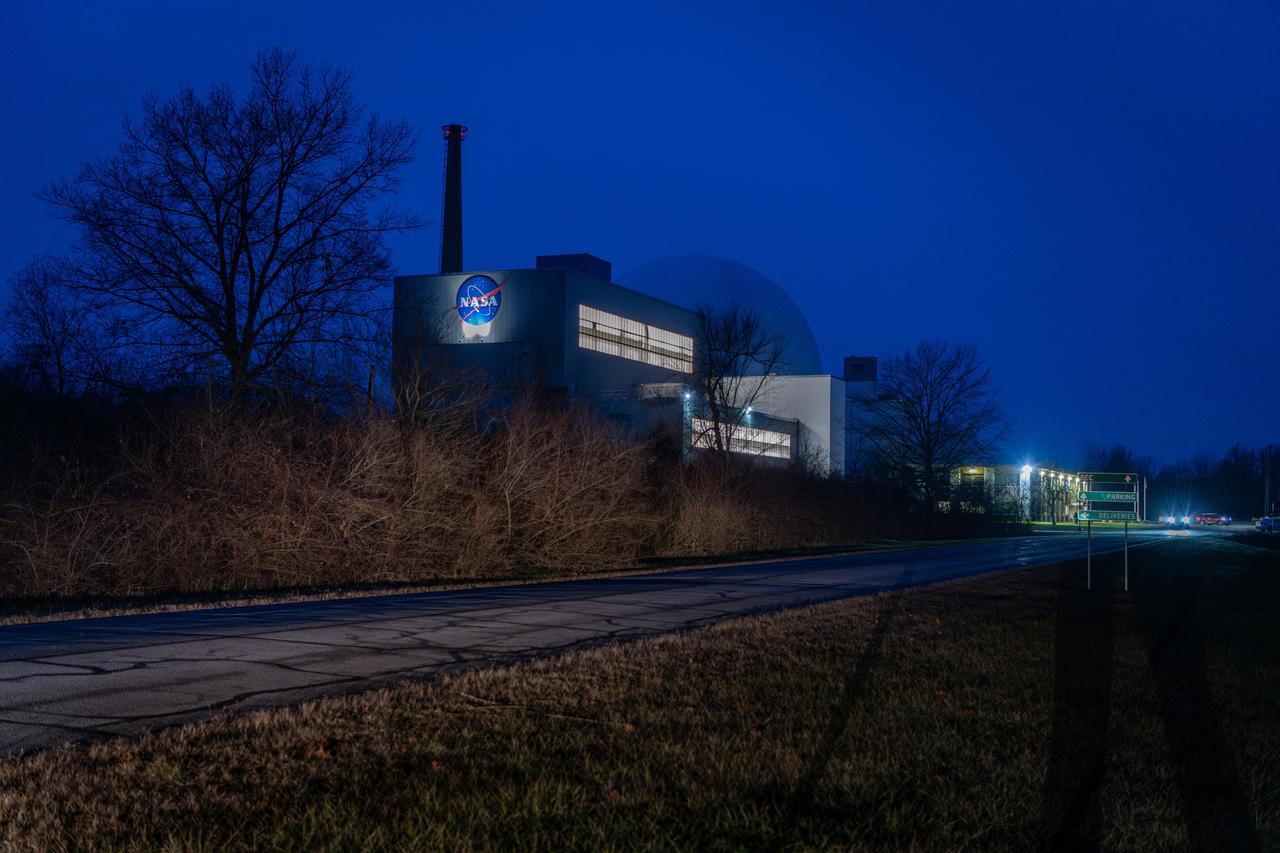
Evening photo of the Space Experiments Complex in the evening of the arrival of the Orion ETA (Environmental Test Article) having been shipped from Florida by truck. The Orion ETA flew on Artemis I and will undergo testing of the docking module jettison and the forward by cover jettison in preparation of the Artemis II launch.

Evening photo of the Space Experiments Complex in the evening of the arrival of the Orion ETA (Environmental Test Article) having been shipped from Florida by truck. The Orion ETA flew on Artemis I and will undergo testing of the docking module jettison and the forward by cover jettison in preparation of the Artemis II launch.
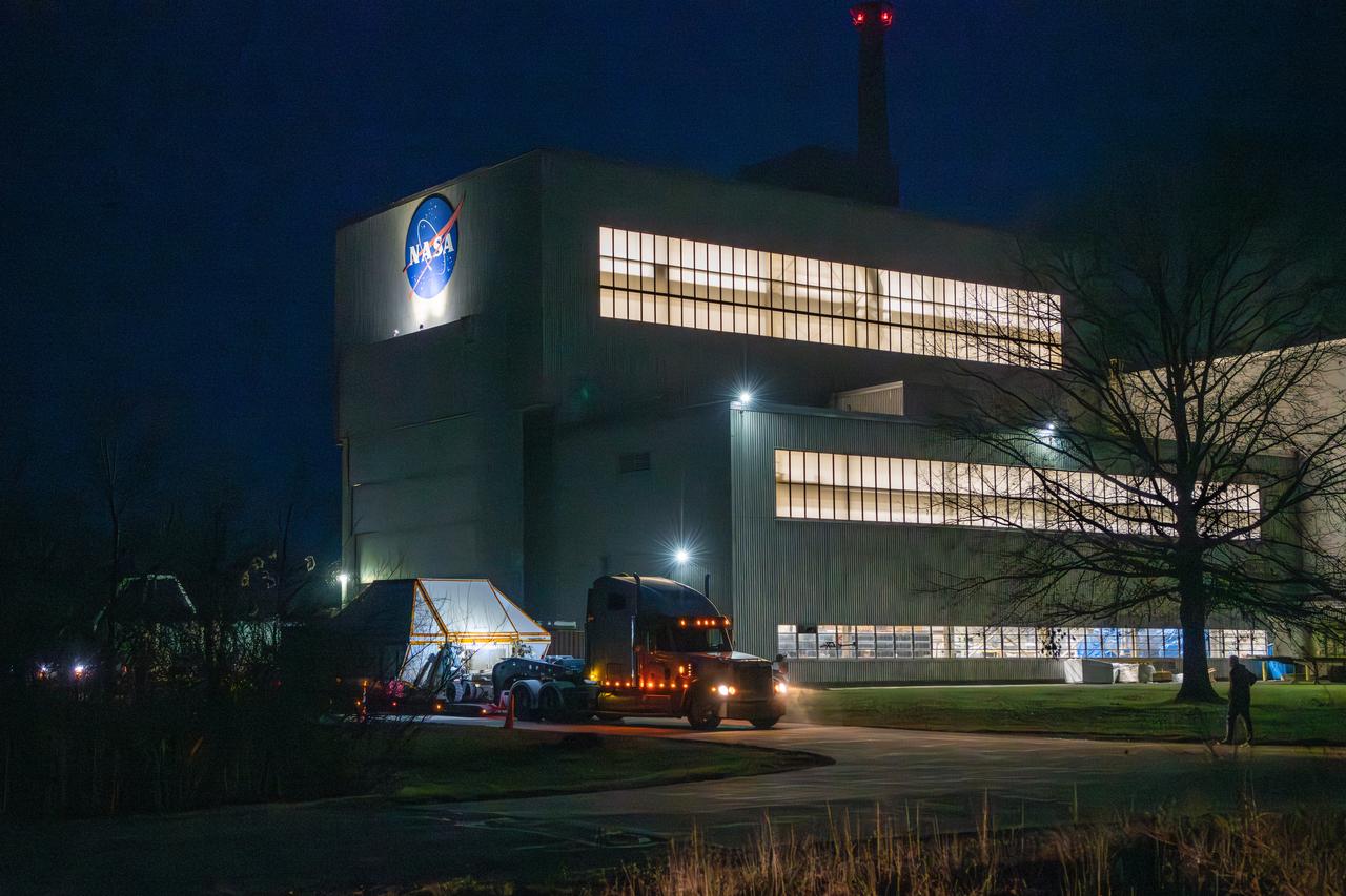
Evening photo of the Space Experiments Complex in the evening of the arrival of the Orion ETA (Environmental Test Article) having been shipped from Florida by truck. The Orion ETA flew on Artemis I and will undergo testing of the docking module jettison and the forward by cover jettison in preparation of the Artemis II launch.
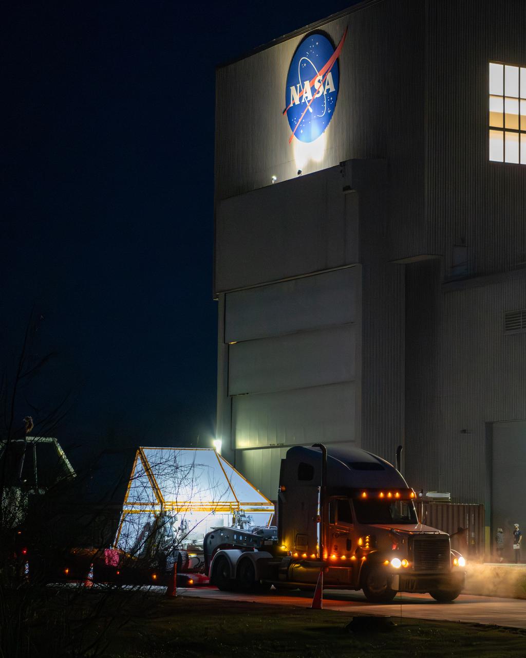
Evening photo of the Space Experiments Complex in the evening of the arrival of the Orion ETA (Environmental Test Article) having been shipped from Florida by truck. The Orion ETA flew on Artemis I and will undergo testing of the docking module jettison and the forward by cover jettison in preparation of the Artemis II launch.
Evening photo of the Space Experiments Complex in the evening of the arrival of the Orion ETA (Environmental Test Article) having been shipped from Florida by truck. The Orion ETA flew on Artemis I and will undergo testing of the docking module jettison and the forward by cover jettison in preparation of the Artemis II launch.
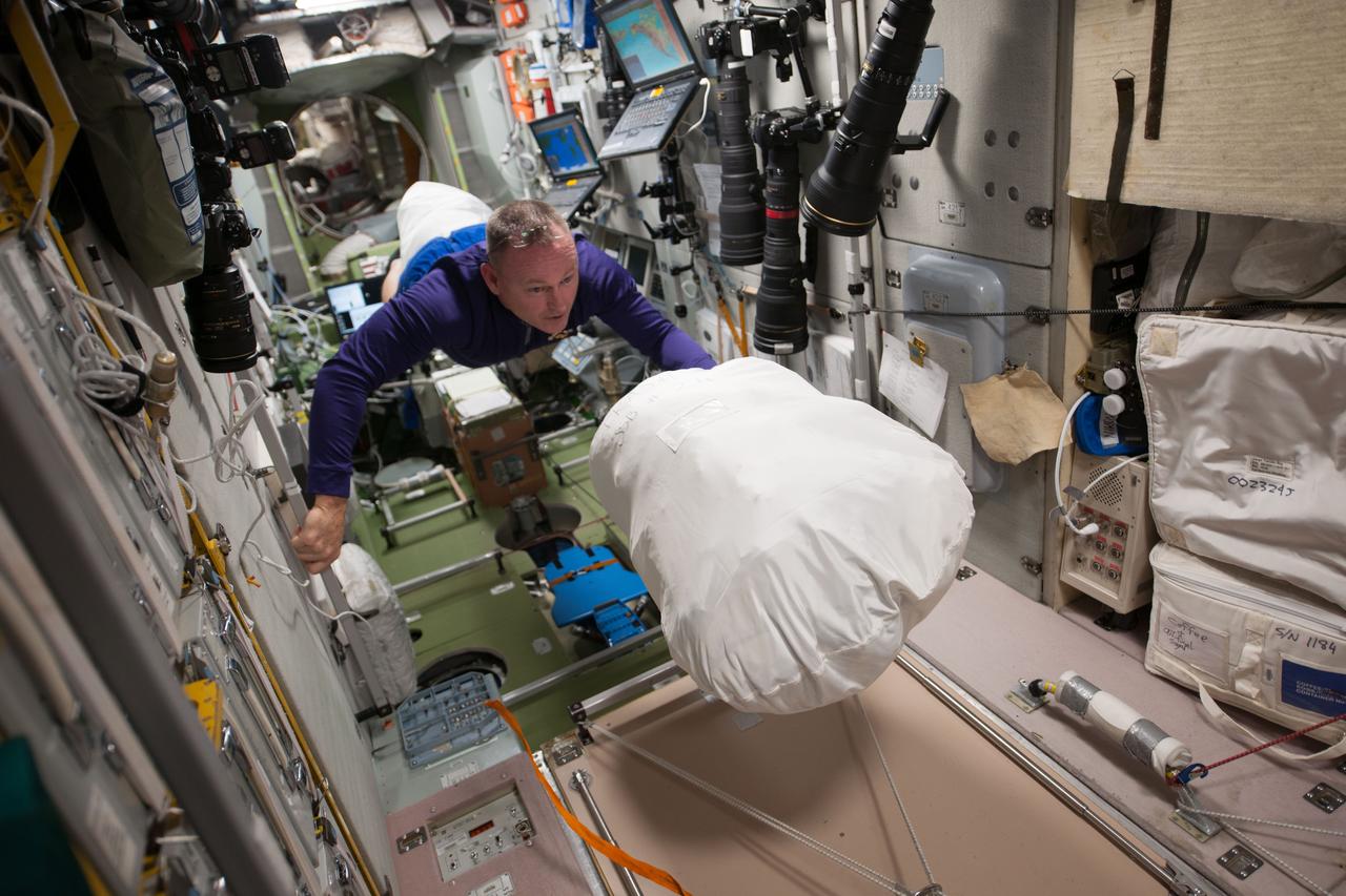
Commander Barry Wilmore floats through the Zvezda Service Module (SM) with a full Jettison Stowage Bag. Image was released by astronaut on Instagram.
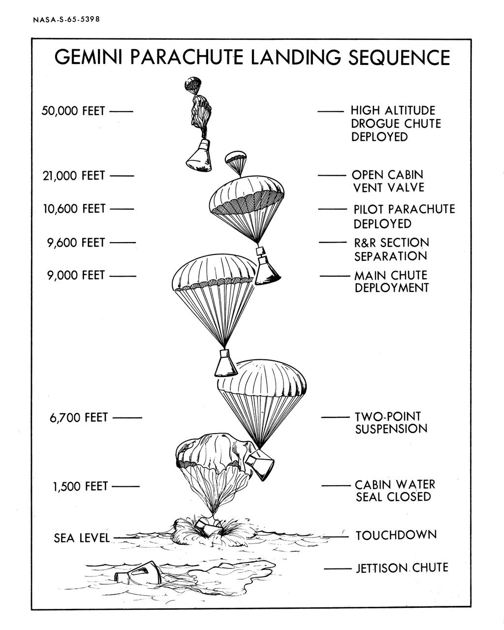
S65-05398 (1965) --- Artist concept of Gemini parachute landing sequence from high altitude drogue chute deployed to jettison of chute.
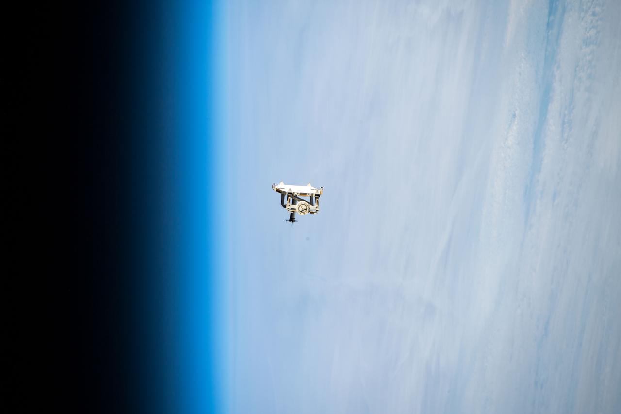
iss068e044261 (Jan. 31, 2023) --- Flight support equipment is pictured descending toward the Earth's atmosphere after being jettisoned from the grips of the Canadarm2 robotic arm. The flight hardware secured a pair of roll-out solar arrays inside SpaceX Dragon cargo ship’s trunk during its ascent to orbit and rendezvous with the International Space Station in November 2022. The jettisoned support equipment drifted safely away from the station and will eventually harmlessly burn up in the atmosphere with no chance for recontacting the space station.
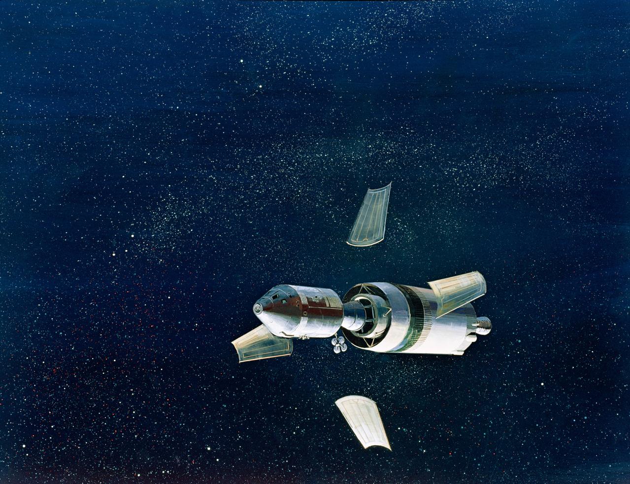
S68-51306 (December 1968) --- North American Rockwell artist's concept illustrating a phase of the scheduled Apollo 8 lunar orbit mission. Here, the Apollo 8 spacecraft lunar module adapter (SLA) panels, which have supported the Command and Service Modules, are jettisoned. This is done by astronauts firing the service module reaction control engines. A signal simultaneously deploys and jettisons the panels, separating the spacecraft from the SLA and deploying the high gain (deep space) antenna.
iss068e044174 (Jan. 31, 2023) --- The Canadarm2 robotic arm is pictured extending away from the International Space Station after jettisoning flight support equipment toward the Earth's atmosphere. The flight hardware secured a pair of roll-out solar arrays inside the SpaceX Dragon cargo ship’s trunk during its ascent to orbit and rendezvous with the space station in November 2022. The jettisoned support equipment drifted safely away from the station and will eventually harmlessly burn up in the atmosphere with no chance for recontacting the space station.

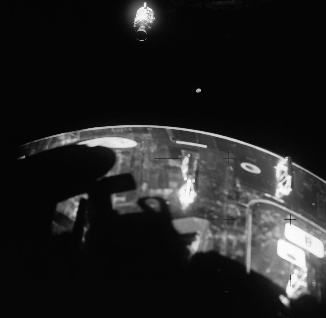
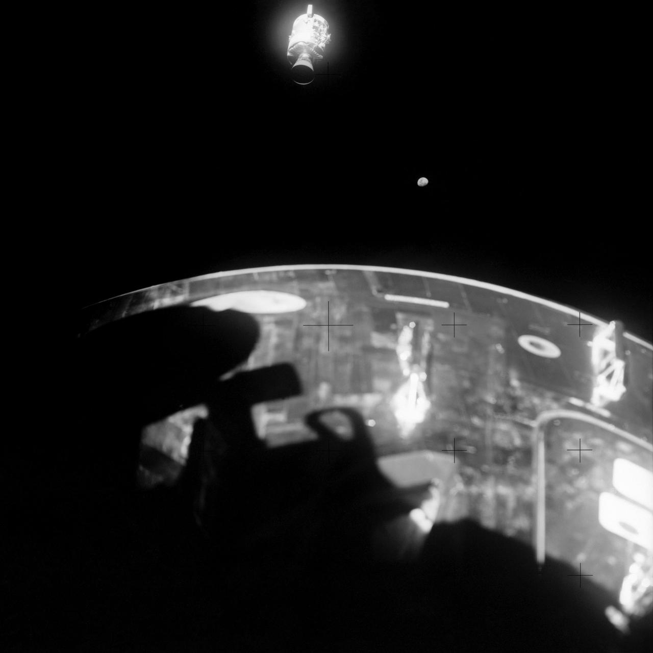
AS13-59-8562 (17 April 1970) --- This view of the Apollo 13 Lunar Module (LM) was photographed from the Command Module (CM) just after the LM had been jettisoned. The jettisoning occurred a few minutes before 11 a.m. (CST), April 17, 1970, just over an hour prior to splashdown of the CM in the south Pacific Ocean. The apparent explosion of oxygen tank number two in the Apollo 13 Service Module (SM) caused the Apollo 13 crew members to rely on the LM as a "lifeboat".
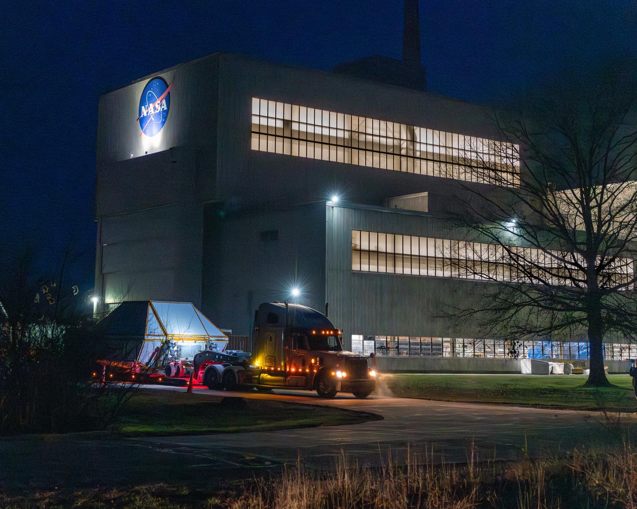
After the evening arrival of the Orion ETA (Environmental Test Article) having been shipped from Florida by truck, is shown being lowered to the floor of the Space Experiments Complex (SEC), Glenn Research Center, Armstrong Test Facility. The Orion ETA will undergo testing of the docking module jettison and the forward by cover jettison in preparation of the Artemis II launch.
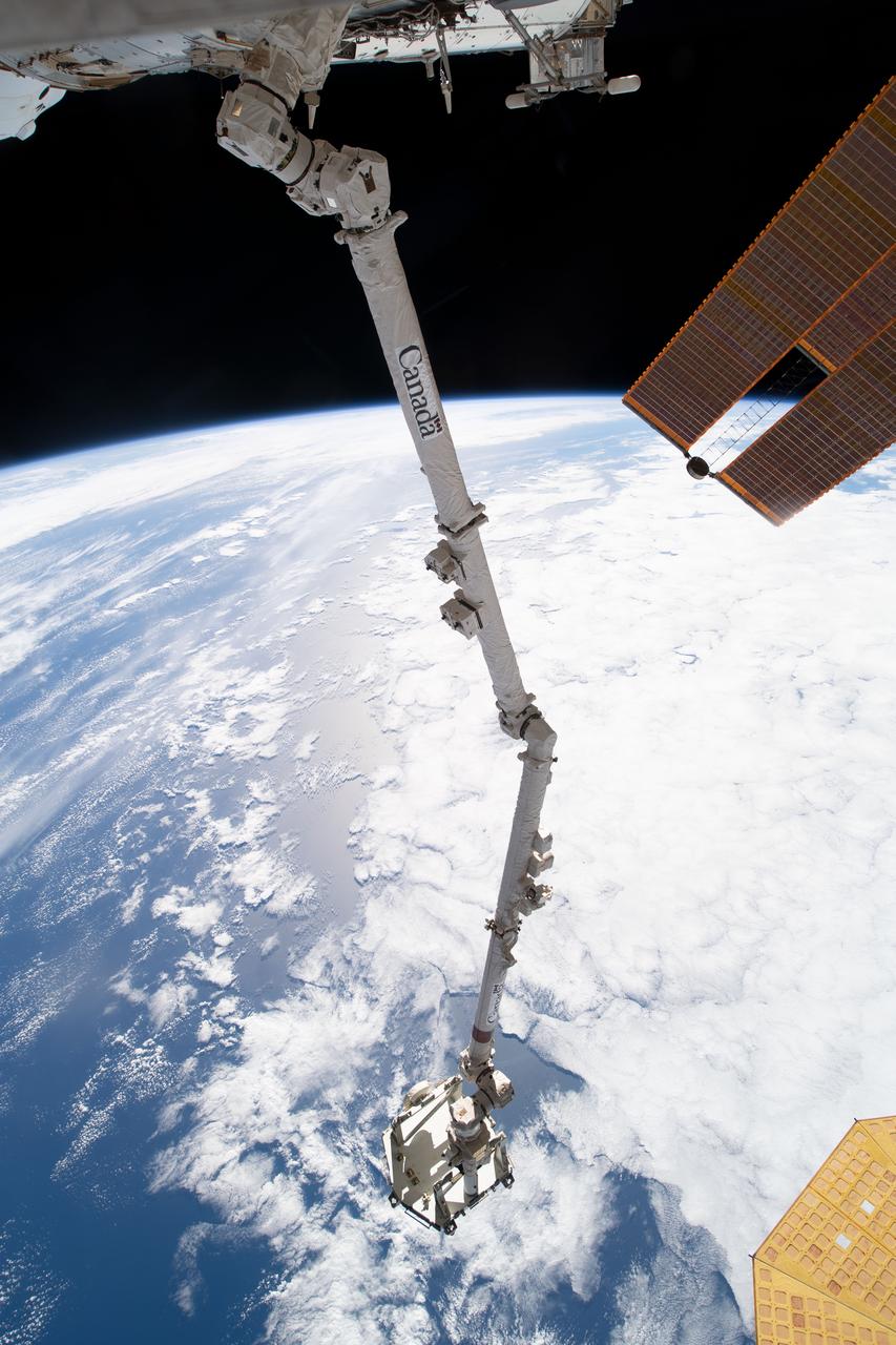
iss068e043860 (Jan. 30, 2023) --- The Canadarm2 robotic arm is pictured extending away from the International Space Station with flight support equipment gripped in its leading end effector before being jettisoned toward the Earth's atmosphere. The flight hardware secured a pair of roll-out solar arrays inside the SpaceX Dragon cargo ship’s trunk during its ascent to orbit and rendezvous with the space station in November 2022. The jettisoned support equipment drifted safely away from the station and will eventually harmlessly burn up in the atmosphere with no chance for recontacting the space station.
AS13-58-8458 (17 April 1970) --- This view of the severely damaged Apollo 13 Service Module (SM) was photographed from the Lunar Module/Command Module (LM/CM) following SM jettisoning. An entire SM panel was blown away by the apparent explosion of oxygen tank number two. Two of the three fuel cells are visible at the forward portion of the opening. The hydrogen tanks are located in Sector 4 of the Apollo 13 SM. The apparent rupture of the oxygen tank caused the Apollo 13 crew members to use the LM as a "lifeboat." The LM was jettisoned just prior to Earth re-entry by the CM.
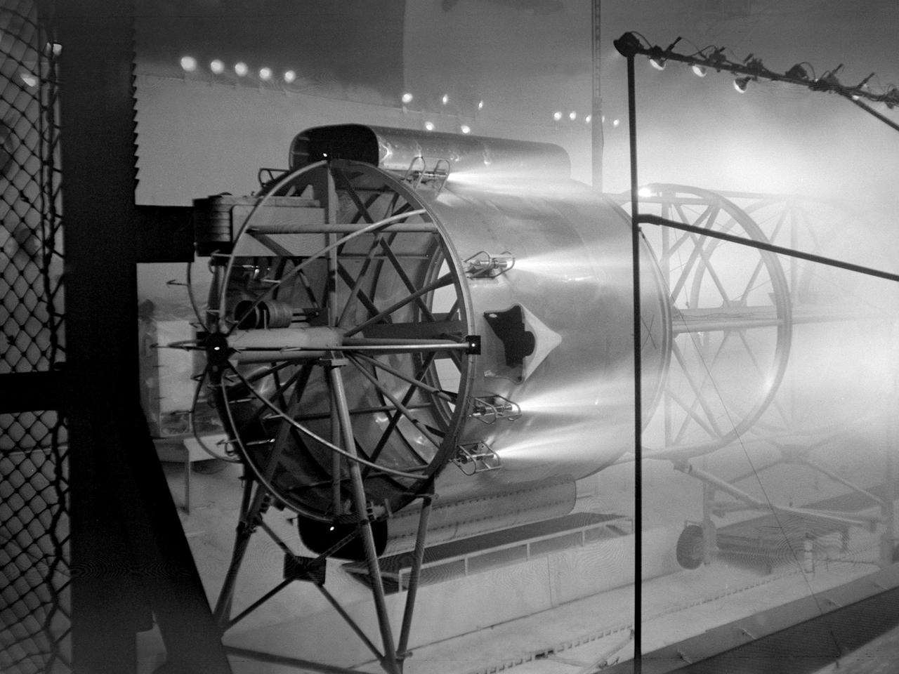
An Atlas/Centaur mass model undergoes a separation test inside the Space Power Chambers at NASA Lewis Research Center. Lewis was in the midst of an extensive effort to prepare the Centaur second-stage rocket for its missions to send the Surveyor spacecraft to the moon as a precursor to the Apollo missions. As part of these preparations, Lewis management decided to convert its Altitude Wind Tunnel into two large test chambers—the Space Power Chambers. The conversion included the removal of the tunnel’s internal components and the insertion of bulkheads to seal off the new chambers within the tunnel. One chamber could simulate conditions found at 100 miles altitude, while this larger chamber simulated the upper atmosphere. In this test series, researchers wanted to verify that the vehicle’s retrorockets would properly separate the Centaur from the Atlas. The model was suspended horizontally on a trolley system inside chamber. A net was hung at one end to catch the jettisoned Atlas model. The chamber atmosphere was reduced to a pressure altitude of 100,000 feet, and high-speed cameras were synchronized to the ignition of the retrorockets. The simulated Centaur is seen here jettisoning from the Atlas out of view to the right. The study resulted in a new jettison method that would significantly reduce the separation time and thus minimize the danger of collision between the two stages during separation.
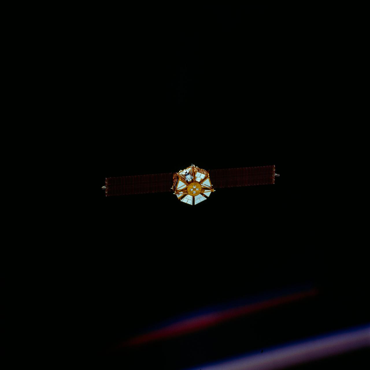
STS072-720-042 (13 Jan. 1996) --- The crew members captured this 70mm view of the Japanese Space Flyer Unit (SFU) just prior to the jettisoning of the solar panels. Later, they used the Remote Manipulator System (RMS) to latch onto the satellite and berth it in the Space Shuttle Endeavour’s aft cargo bay.
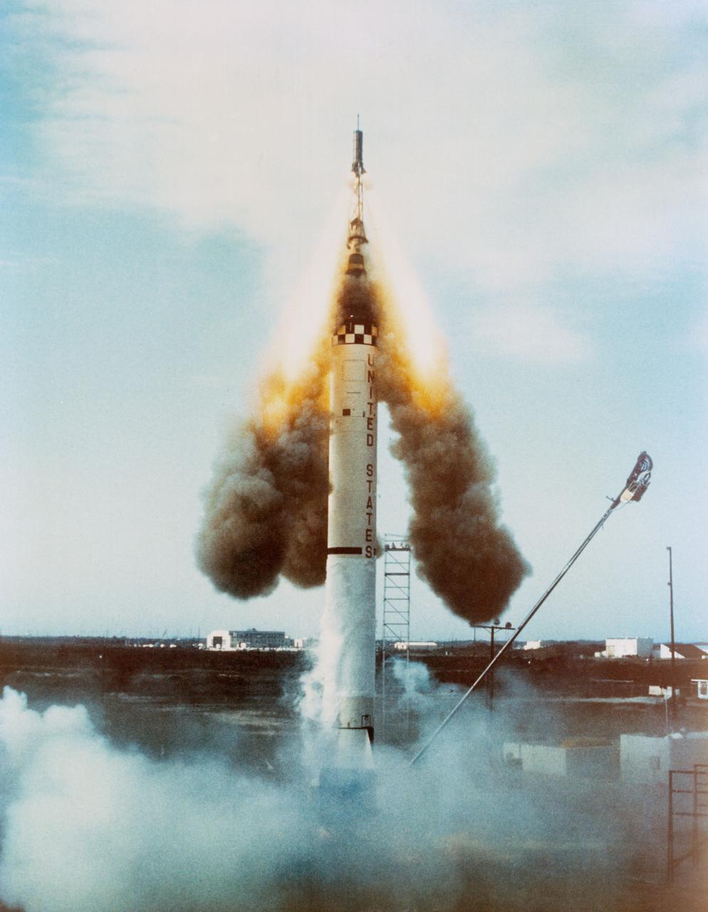
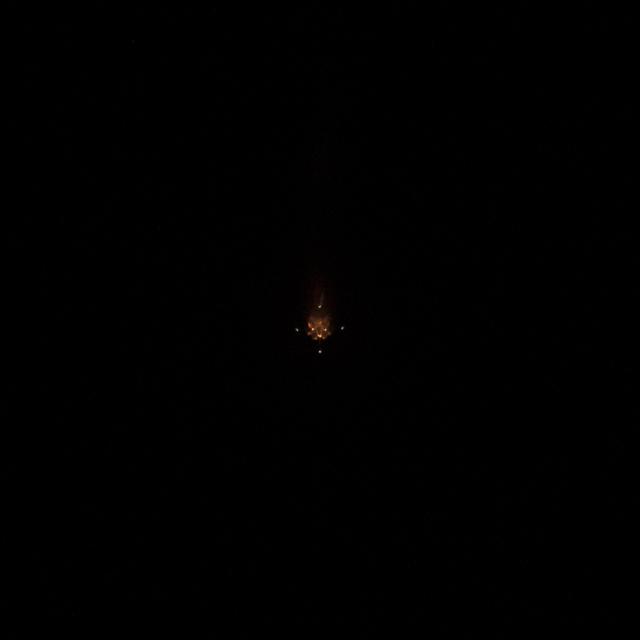
S63-00193 (29 July 1960) --- Launch of the unmanned Mercury-Atlas 1 (MA-1) from Cape Canaveral, Florida. Premature engine cutoff at launch terminated the test. Emergency escape system jettisoned. The Altas exploded 65 seconds after launch. Photo credit: NASA

Portrait of Orion Service Module Spacecraft Adapter Jettisonable (SAJ) Hardware Lead Engineer Lizalyn Smith. Ms. Smith participated in various 'Hidden Figures to Modern Figures' events sponsored by NASA Glenn Research Center to encourage students to pursue STEM-based careers.
The spacecraft adapter jettison fairing panels are installed on the Exploration Flight Test-1 (EFT-1) Orion service module in the Operations and Checkout (O&C) Building at Kennedy Space Center on Jan. 14 , 2014. Part of Batch image transfer from Flickr.
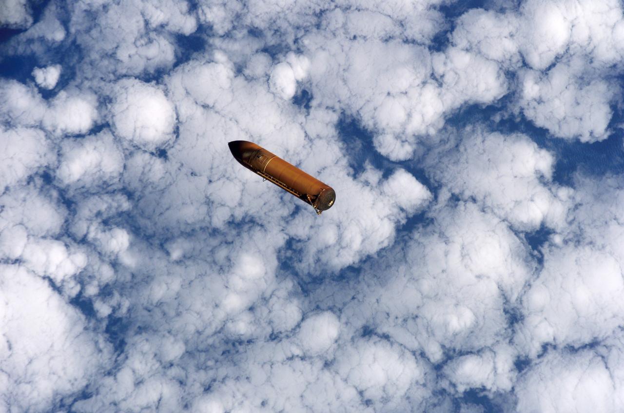
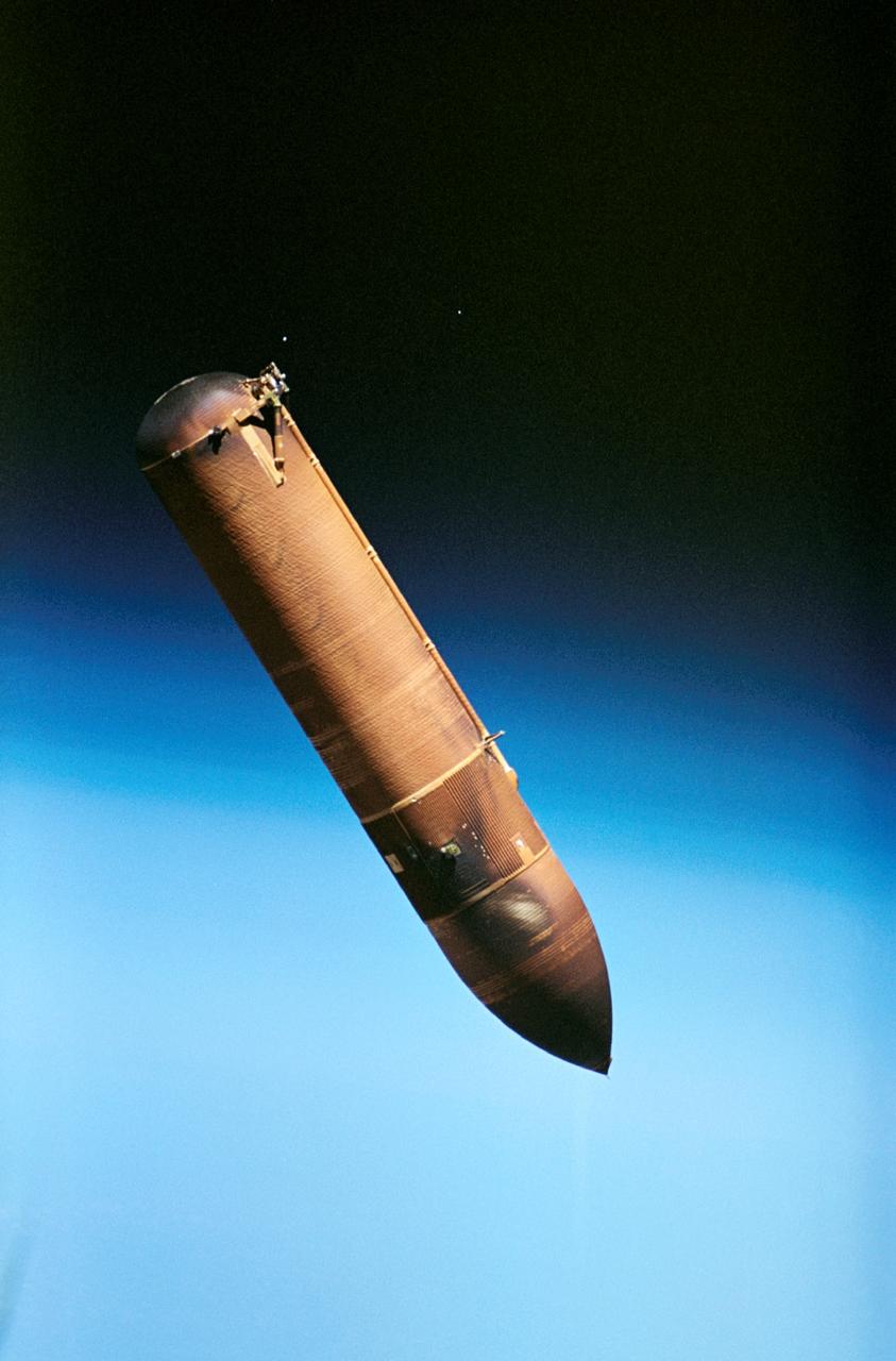
S114-E-5122 (26 July 2005) --- The external fuel tank is jettisoned from the Space Shuttle Discovery and falls toward Earth’s atmosphere during the completion of the launch phase of the STS-114 mission. A blue and white Earth forms the backdrop for this image.
The spacecraft adapter jettison fairing panels are installed on the Exploration Flight Test-1 (EFT-1) Orion service module in the Operations and Checkout (O&C) Building at Kennedy Space Center on Jan. 14 , 2014. Part of Batch image transfer from Flickr.
Lockheed Martin technicians work on a Exploration Flight Test-1 (EFT-1) spacecraft adapter jettison fairing at NASA's Michoud Assembly Facility in New Orleans on Nov. 10, 2011. Part of Batch image transfer from Flickr.
S81-33180 (12 April 1981) --- The two solid rocket boosters are jettisoned from the climbing space shuttle Columbia as a successful launch phase continues for NASA's first manned space mission since 1975. Astronauts John W. Young and Robert L. Crippen are aboard the Columbia. Photo credit: NASA
The spacecraft adapter jettison fairing panels are installed on the Exploration Flight Test-1 (EFT-1) Orion service module in the Operations and Checkout (O&C) Building at Kennedy Space Center on Jan. 14 , 2014. Part of Batch image transfer from Flickr.
The spacecraft adapter jettison fairing panels are installed on the Exploration Flight Test-1 (EFT-1) Orion service module in the Operations and Checkout (O&C) Building at Kennedy Space Center on Jan. 14 , 2014. Part of Batch image transfer from Flickr.
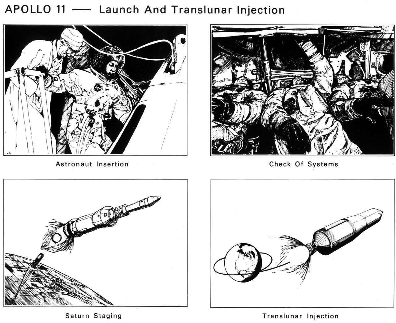
The astronauts enter the spacecraft. After launch and Saturn V first-stage burnout and jettison, the S-II second stage ignites. The crew checks spacecraft systems in Earth orbit before the S-IVB third stage ignites the second time to send Apollo 11 to the Moon
S81-33178 (12 April 1981) --- The two solid rocket boosters are jettisoned from the climbing space shuttle Columbia as a successful launch phase continues for NASA's first manned space mission since 1975. Astronauts John W. Young and Robert L. Crippen are aboard Columbia. Photo credit: NASA
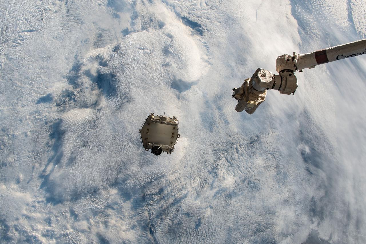
iss067e173472 (July 3, 2022) --- A trash container is pictured on a trajectory away from the International Space Station and toward the Earth's atmosphere for a fiery, but safe disposal. The trash container had been jettisoned moments earlier from the Nanoracks Bishop Airlock while attached to the Canadarm2 robotic arm.
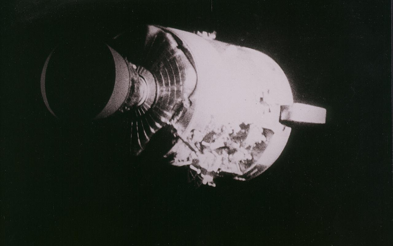
Apollo 13 onboard photo: This view of the severely damaged Apollo 13 Service Module was photographed from the Lunar Module/Command Module following the jettison of the Service Module. As seen here, an entire panel of the Service Module was blown away by the apparent explosion of oxygen tank number two located in Sector 4 of the Service Module. Two of the three fuel cells are visible just forward (above) the heavily damaged area. Three fuel cells, two oxygen tanks, and two hydrogen tanks, are located in Sector 4. The damaged area is located above the S-band high gain anterna. Nearest the camera is the Service Propulsion System (SPS) engine and nozzle. The damage to the Service Module caused the Apollo 13 crewmen to use the Lunar Module as a lifeboat. The Lunar Module was jettisoned by the Command Module just prior to Earth re-entry.
This view of the damaged Apollo 13 Service Module (SM) was photographed from the Lunar Module/Command Module following SM jettisoning. As seen here, an entire panel on the SM was blown away by the apparent explosion of oxygen tank number two located in Sector 4 of the SM. Two of the three fuel cells are visible just forward (above) the heavily damaged area. Three fuel cells, two oxygen tanks, and two hydrogen tanks are locate in Sector 4. The damaged area is located above the S-band high gain antenna. Nearest the camera is the Service Propulsion System (SPS) engine and nozzle. The damage to the SM caused the Apollo 13 crewmen to use the Lunar Module (LM) as a "lifeboat". The LM was jettisoned just prior to Earth reentry by the Command Module.
AS13-59-8501 (17 April 1970) --- This view of the severely damaged Apollo 13 Service Module (SM) was photographed from the Lunar Module/Command Module (LM/CM) following SM jettisoning. As seen here, an entire panel on the SM was blown away by the apparent explosion of oxygen tank number two located in Sector 4 of the SM. Two of the three fuel cells are visible just forward (above) the heavily damaged area. Three fuel cells, two oxygen tanks, and two hydrogen tanks are located in Sector 4. The damaged area is located above the S-Band high gain antenna. Nearest the camera is the Service Propulsion System (SPS) engine and nozzle. The damage to the SM caused the Apollo 13 crew men to use the LM as a "lifeboat." The LM was jettisoned just prior to Earth re-entry by the CM.
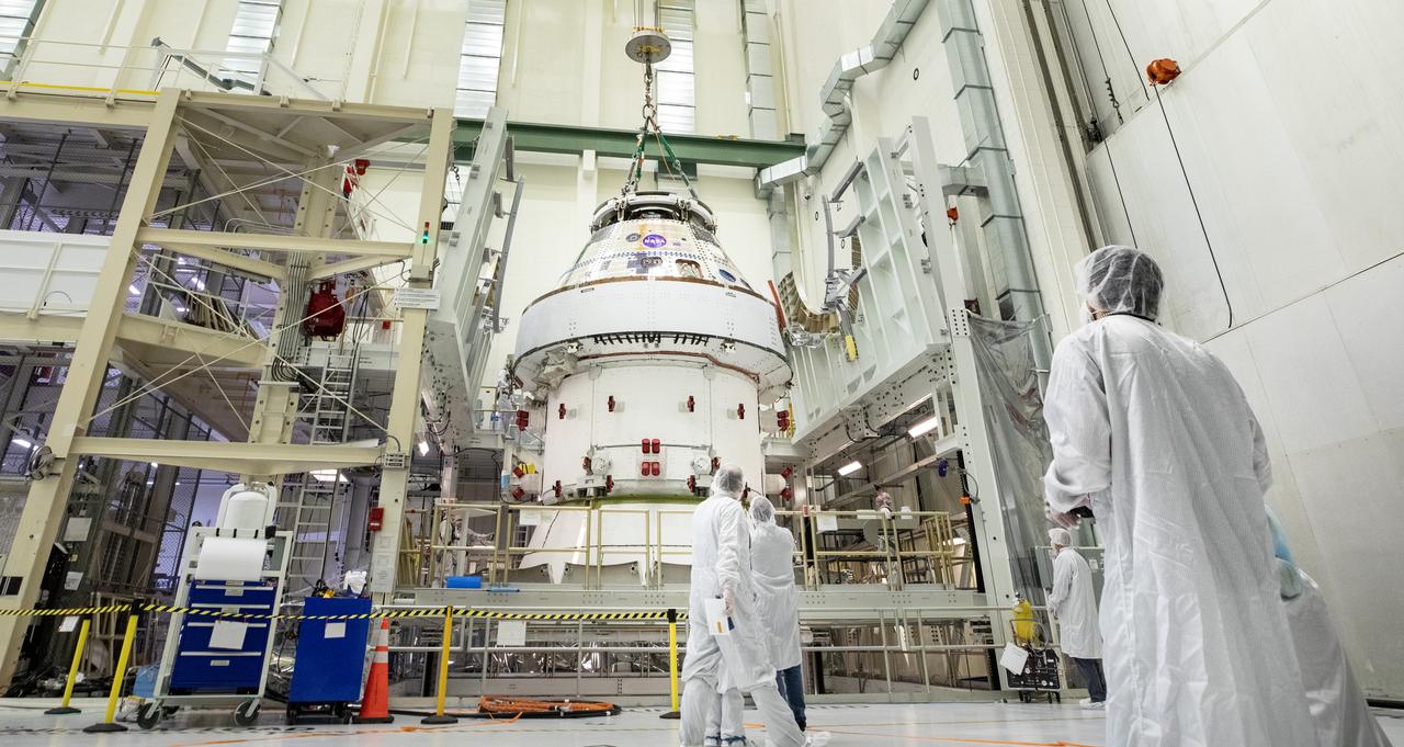
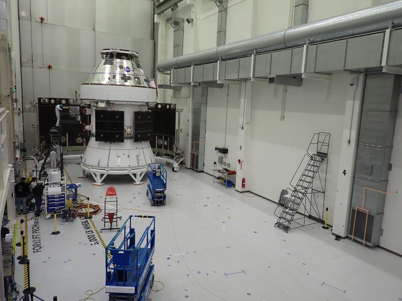
Technicians with NASA and Lockheed Martin operate a 30-ton crane to move NASA’s Artemis II Orion spacecraft out of the Final Assembly and System Testing cell inside the Neil A. Operations and Checkout Building at NASA’s Kennedy Space Center in Florida on Saturday, Feb. 22, 2025. The move prepares for the upcoming installation of four solar array wings and spacecraft adapter jettison fairings for the agency’s first crewed flight test under the Artemis campaign.
The Soyuz MS-08 rocket boosters are seen being jettisoned during launch from the Baikonur Cosmodrome, Wednesday, March 21, 2018 in Kazakhstan. Expedition 55 Soyuz Commander Oleg Artemyev of Roscosmosand flight engineers Ricky Arnold and Drew Feustel of NASA will spend the next five months living and working aboard the International Space Station. Photo Credit: (NASA/Joel Kowsky)