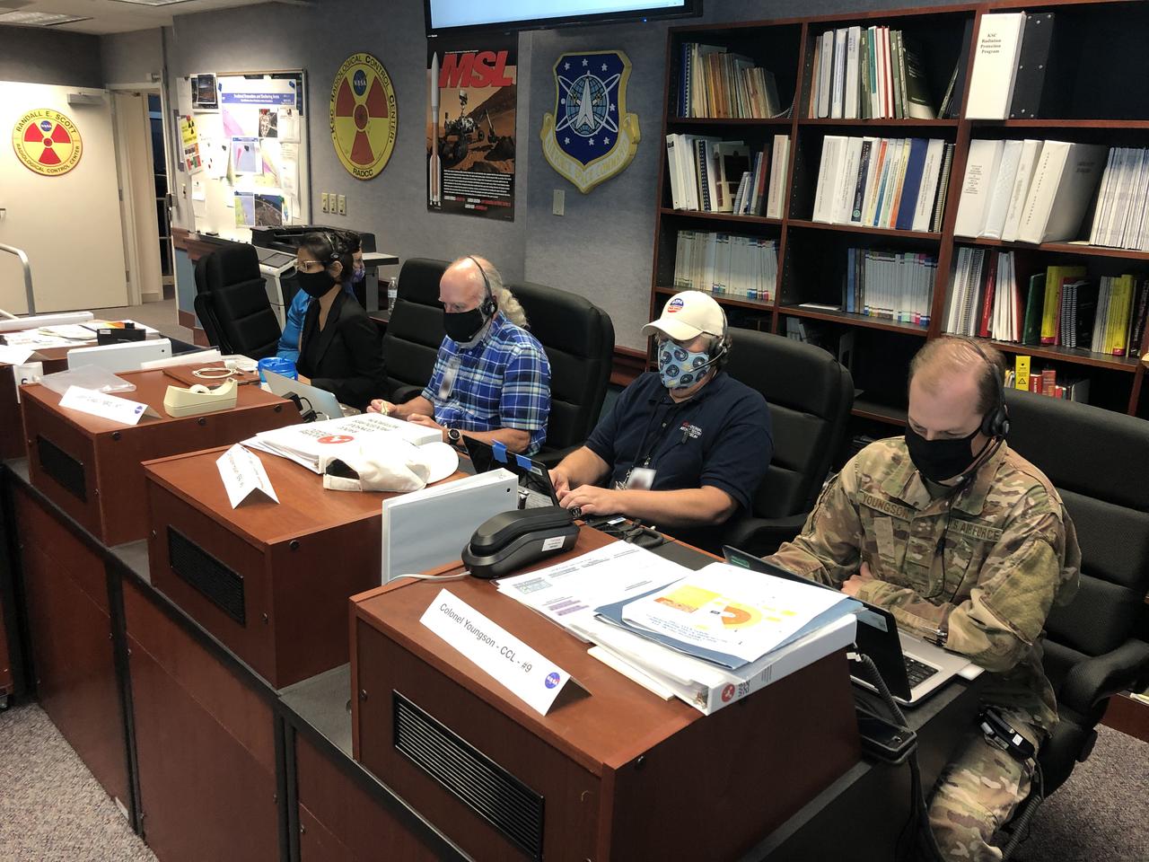
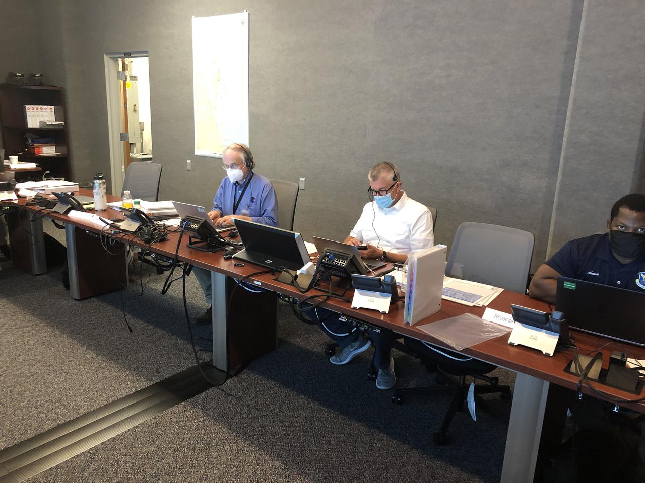
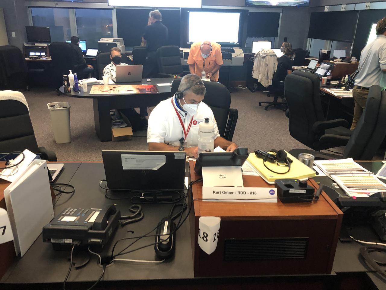
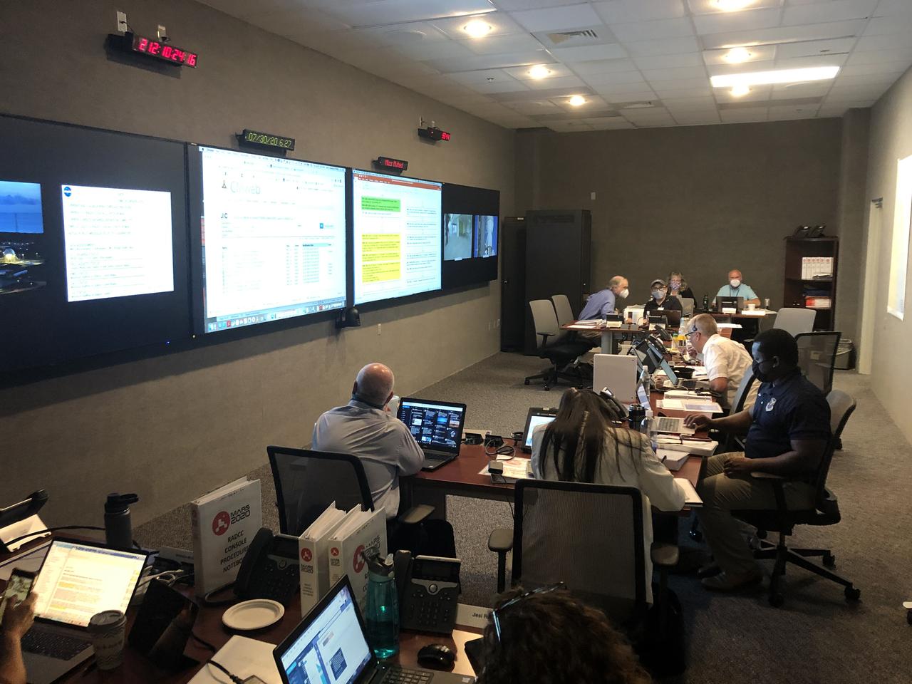
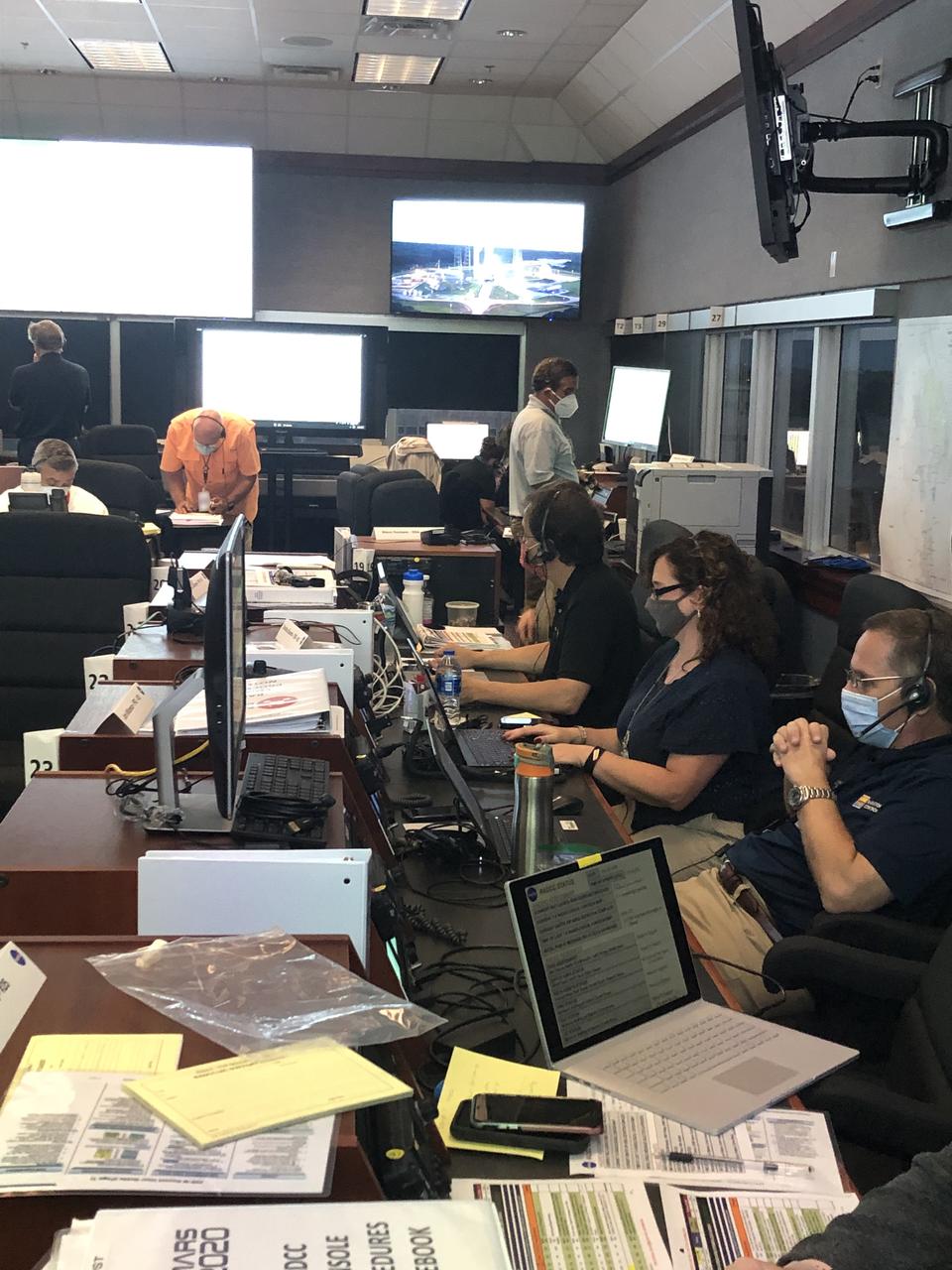
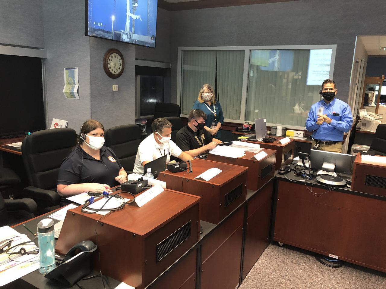
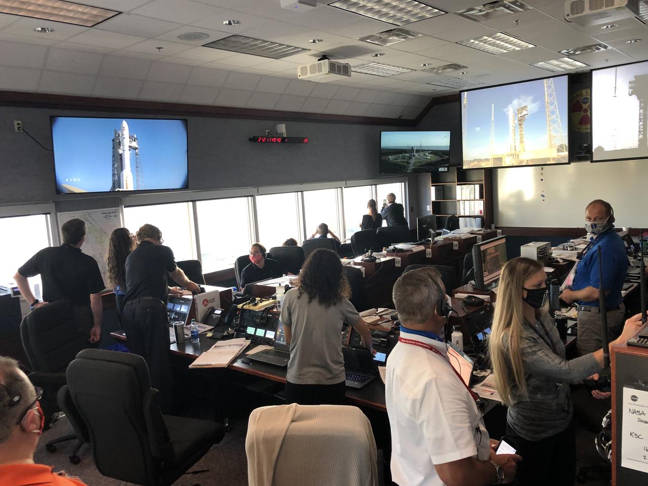
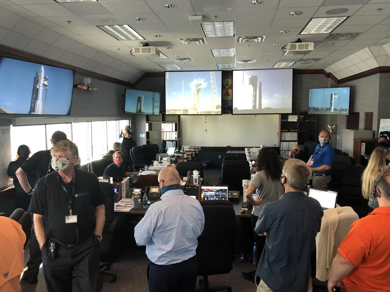
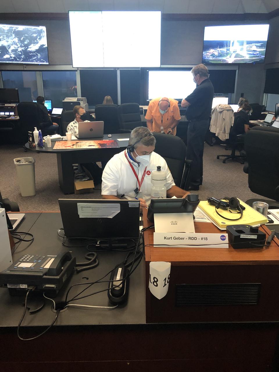
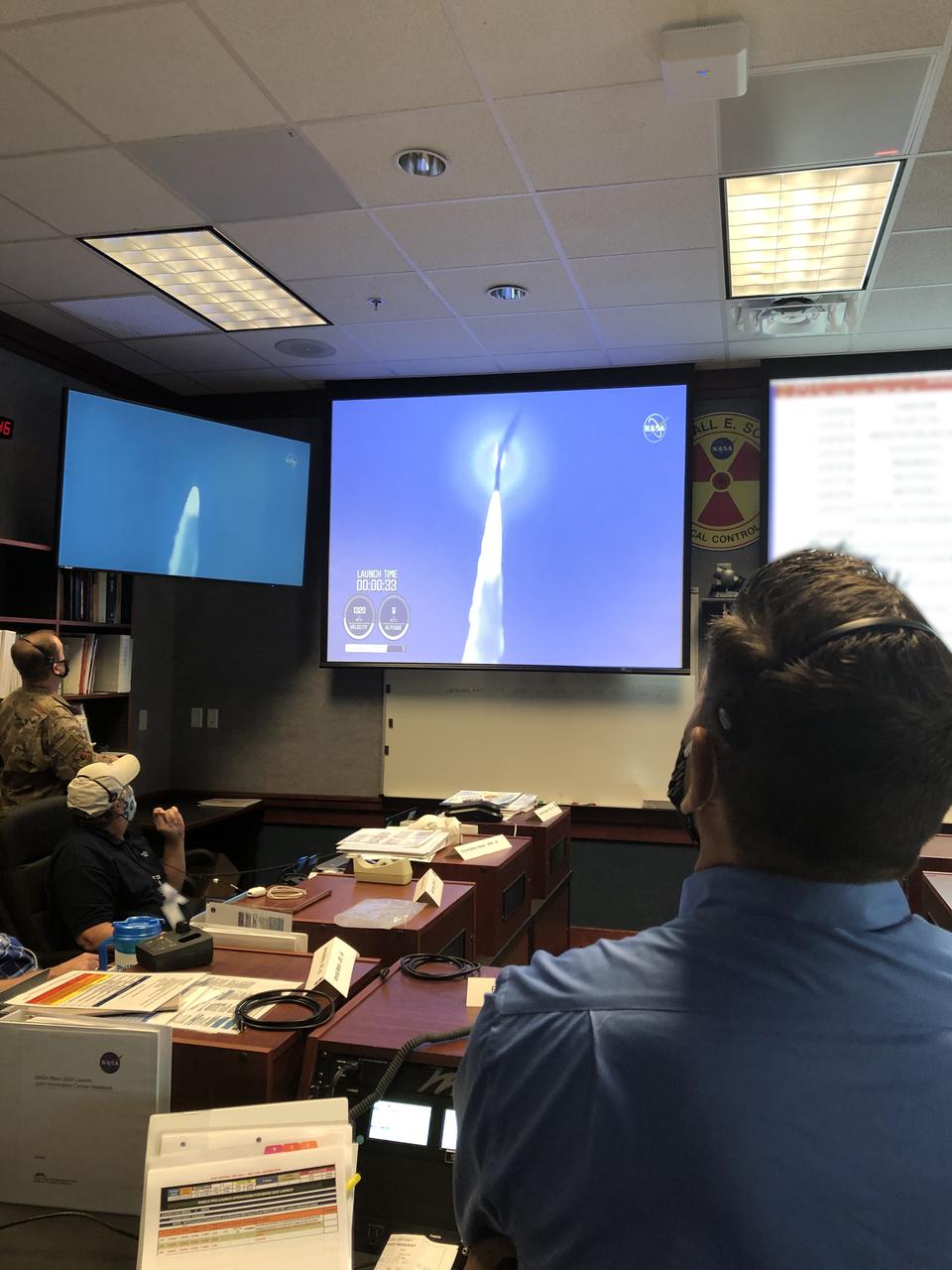
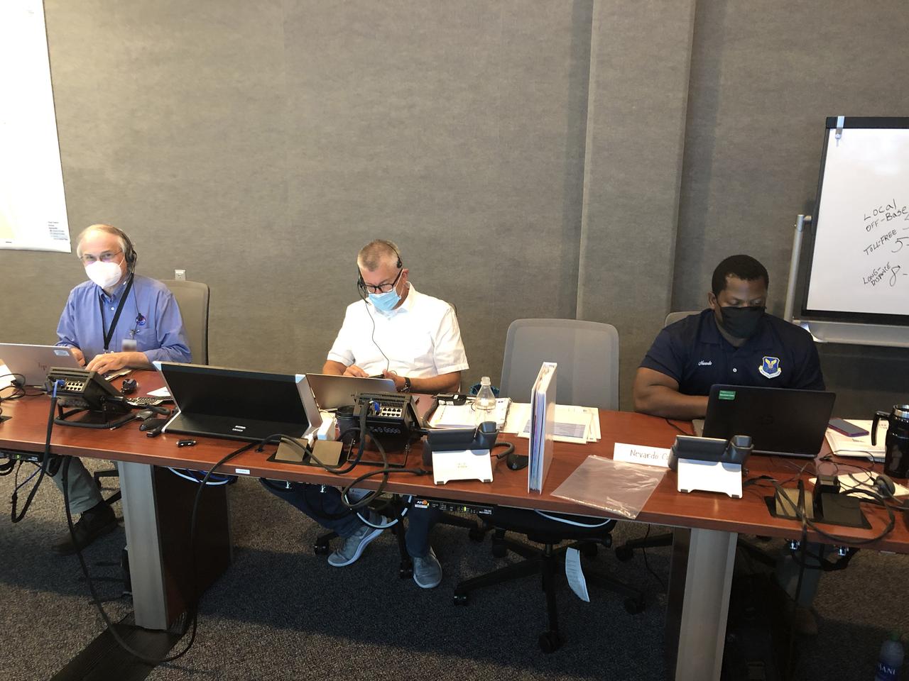
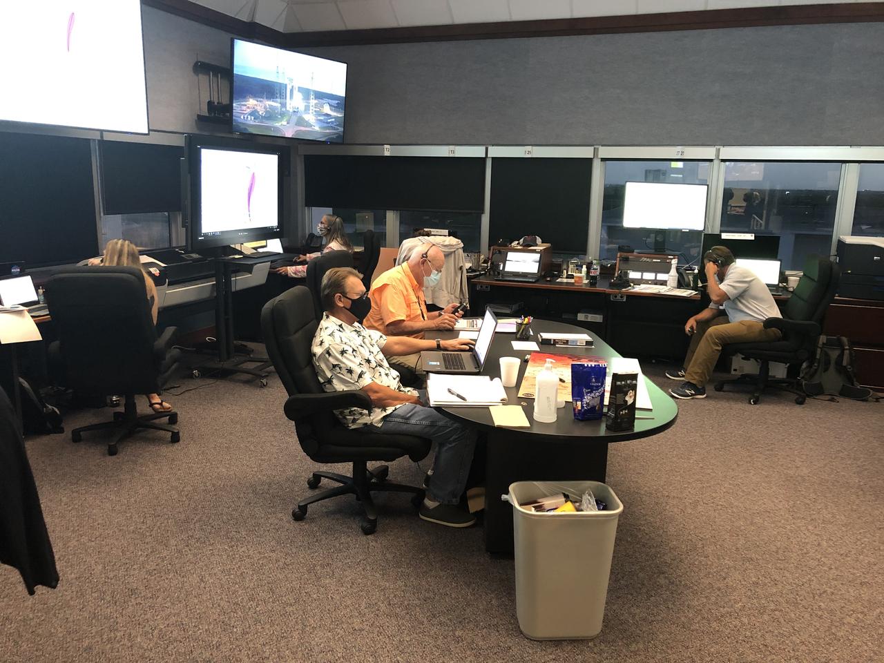
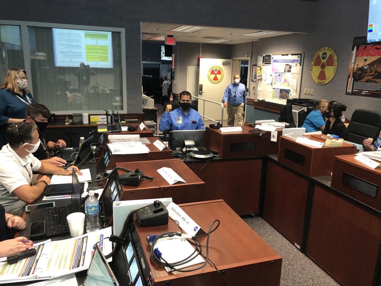
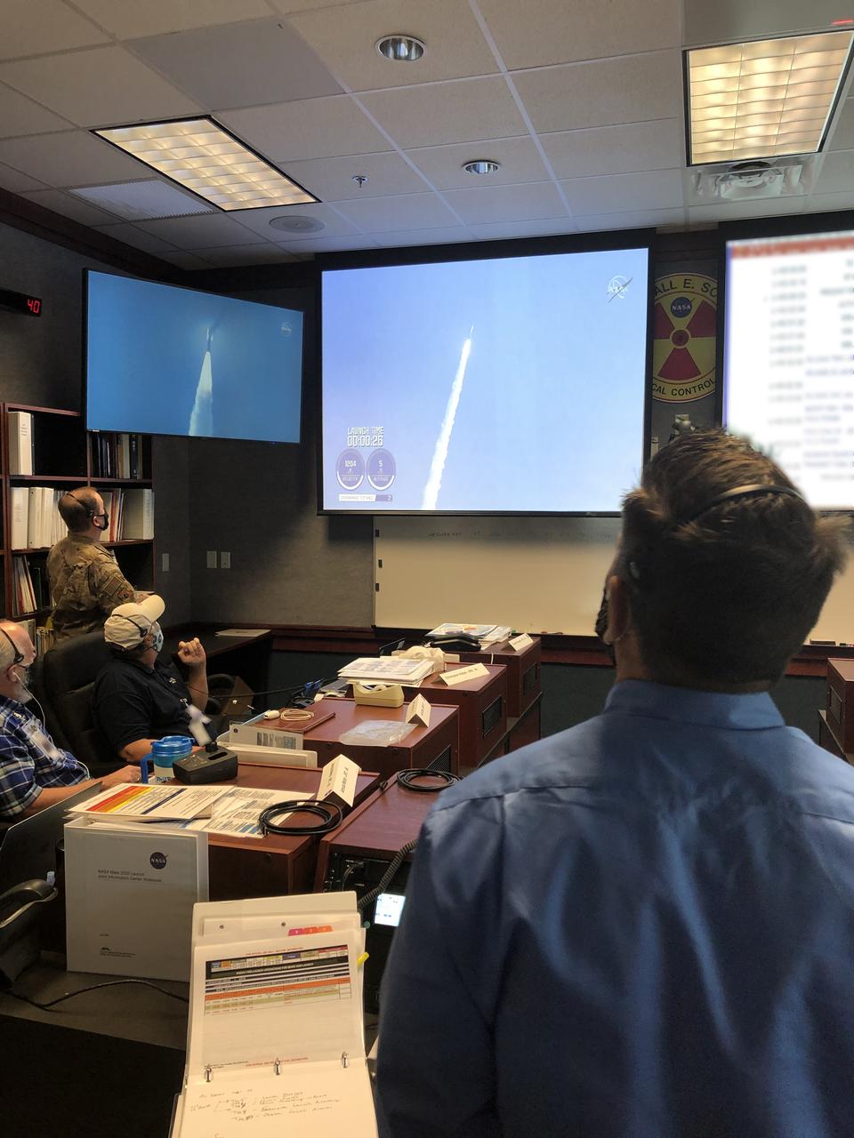
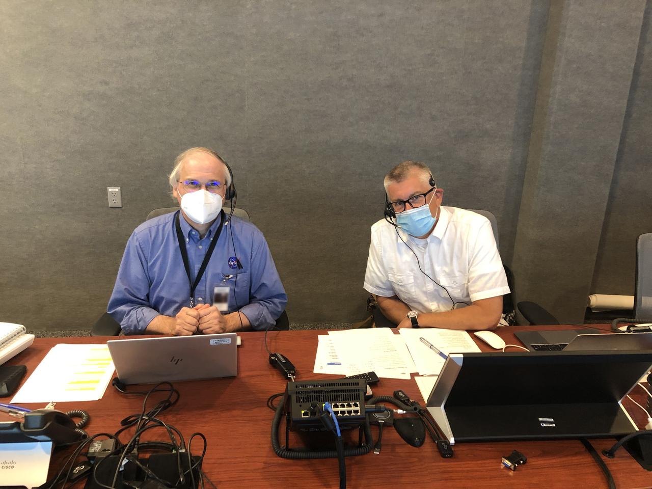
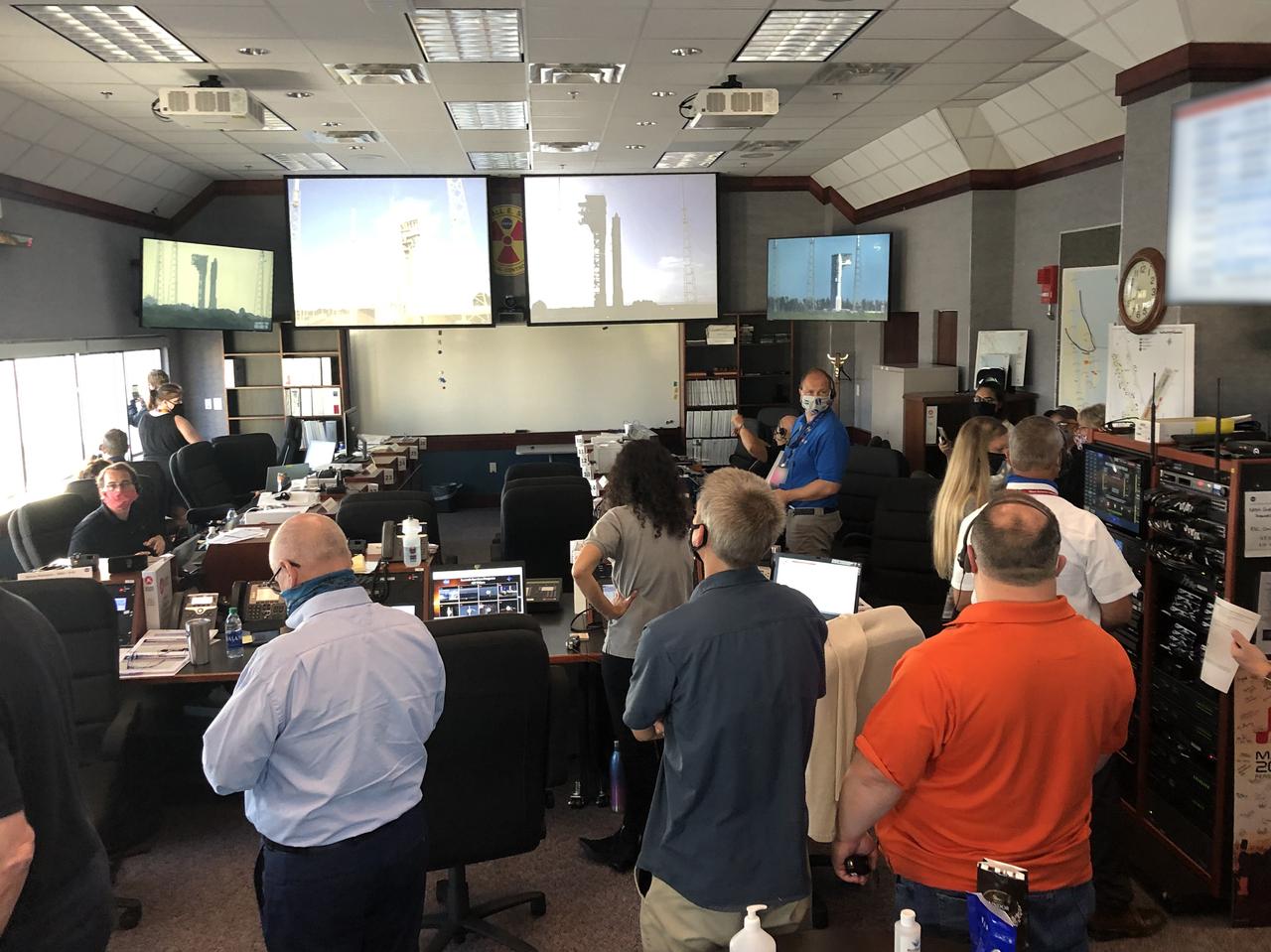
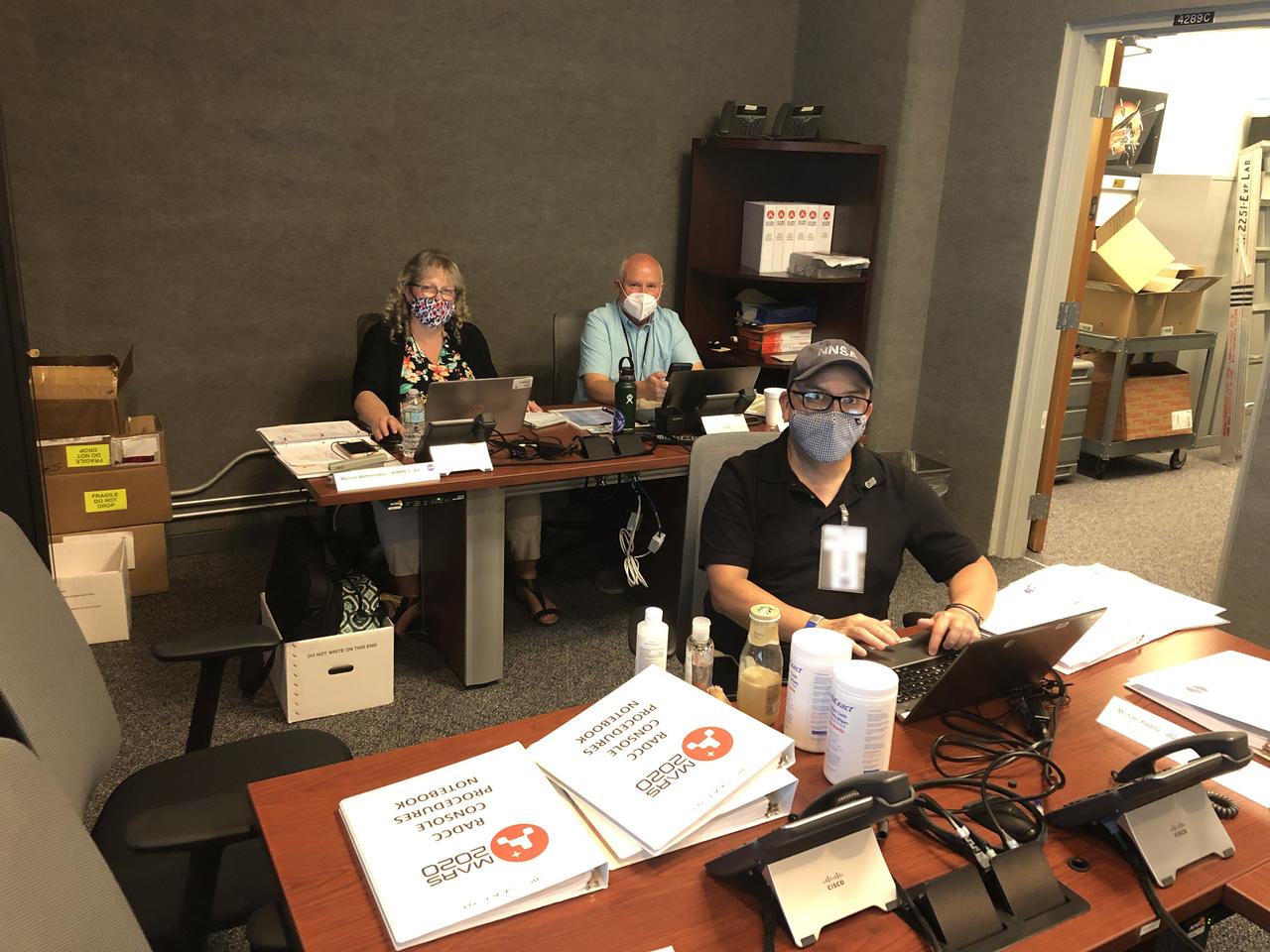
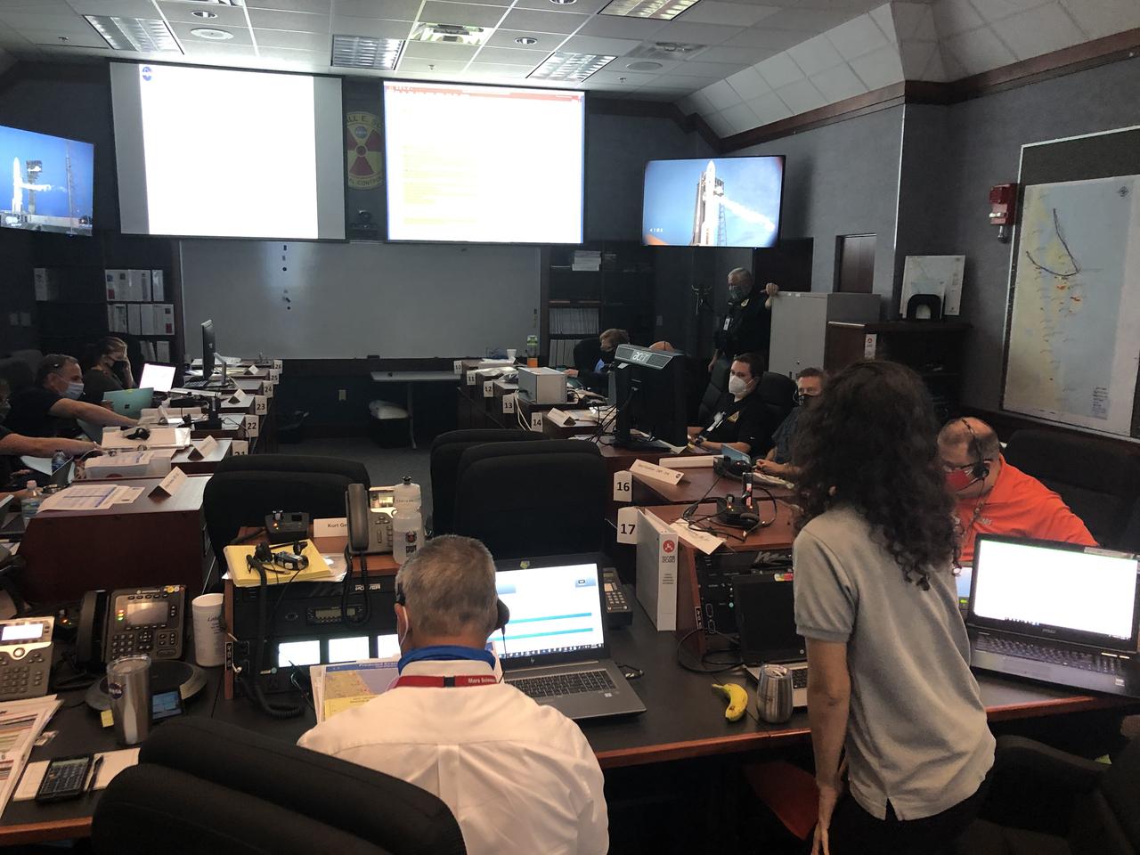
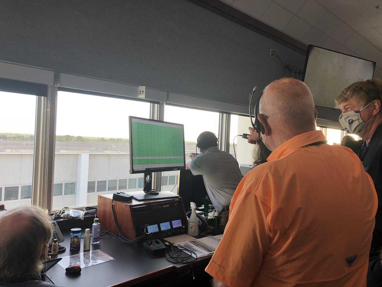
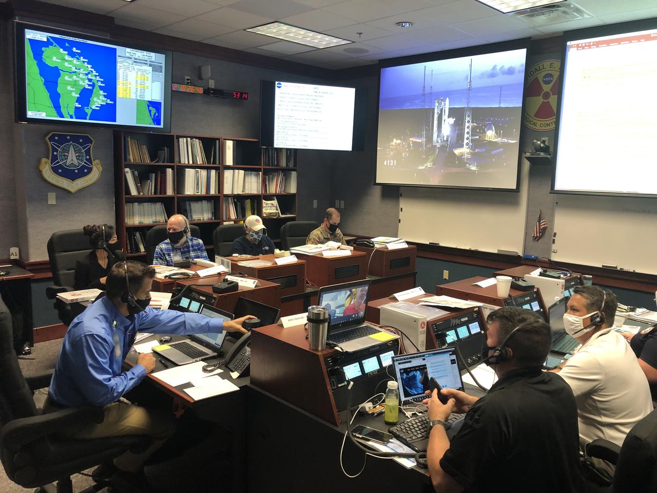
Joint Information Center (JIC), Emergency Operations Center (EOC) and Radiation Control Center (RADCC) members prepare for the launch of NASA’s Mars 2020 Perseverance rover and Ingenuity helicopter on July 30, 2020, at the agency’s Kennedy Space Center in Florida. JIC members include representatives on the local, regional and national level. Mars 2020 launched on a United Launch Alliance Atlas V 541 rocket from Space Launch Complex 41 at nearby Cape Canaveral Air Force Station. Liftoff was at 7:50 a.m. EDT. The rover is part of NASA’s Mars Exploration Program, a long-term effort of robotic exploration of the Red Planet. The rover will search for habitable conditions in the ancient past and signs of past microbial life on Mars. The Launch Services Program at Kennedy is responsible for launch management.

Joint Information Center (JIC), Emergency Operations Center (EOC) and Radiation Control Center (RADCC) members prepare for the launch of NASA’s Mars 2020 Perseverance rover and Ingenuity helicopter on July 30, 2020, at the agency’s Kennedy Space Center in Florida. JIC members include representatives on the local, regional and national level. Mars 2020 launched on a United Launch Alliance Atlas V 541 rocket from Space Launch Complex 41 at nearby Cape Canaveral Air Force Station. Liftoff was at 7:50 a.m. EDT. The rover is part of NASA’s Mars Exploration Program, a long-term effort of robotic exploration of the Red Planet. The rover will search for habitable conditions in the ancient past and signs of past microbial life on Mars. The Launch Services Program at Kennedy is responsible for launch management.
Joint Information Center (JIC), Emergency Operations Center (EOC) and Radiation Control Center (RADCC) members prepare for the launch of NASA’s Mars 2020 Perseverance rover and Ingenuity helicopter on July 30, 2020, at the agency’s Kennedy Space Center in Florida. JIC members include representatives on the local, regional and national level. Mars 2020 launched on a United Launch Alliance Atlas V 541 rocket from Space Launch Complex 41 at nearby Cape Canaveral Air Force Station. Liftoff was at 7:50 a.m. EDT. The rover is part of NASA’s Mars Exploration Program, a long-term effort of robotic exploration of the Red Planet. The rover will search for habitable conditions in the ancient past and signs of past microbial life on Mars. The Launch Services Program at Kennedy is responsible for launch management.
Joint Information Center (JIC), Emergency Operations Center (EOC) and Radiation Control Center (RADCC) members prepare for the launch of NASA’s Mars 2020 Perseverance rover and Ingenuity helicopter on July 30, 2020, at the agency’s Kennedy Space Center in Florida. JIC members include representatives on the local, regional and national level. Mars 2020 launched on a United Launch Alliance Atlas V 541 rocket from Space Launch Complex 41 at nearby Cape Canaveral Air Force Station. Liftoff was at 7:50 a.m. EDT. The rover is part of NASA’s Mars Exploration Program, a long-term effort of robotic exploration of the Red Planet. The rover will search for habitable conditions in the ancient past and signs of past microbial life on Mars. The Launch Services Program at Kennedy is responsible for launch management.
Joint Information Center (JIC), Emergency Operations Center (EOC) and Radiation Control Center (RADCC) members prepare for the launch of NASA’s Mars 2020 Perseverance rover and Ingenuity helicopter on July 30, 2020, at the agency’s Kennedy Space Center in Florida. JIC members include representatives on the local, regional and national level. Mars 2020 launched on a United Launch Alliance Atlas V 541 rocket from Space Launch Complex 41 at nearby Cape Canaveral Air Force Station. Liftoff was at 7:50 a.m. EDT. The rover is part of NASA’s Mars Exploration Program, a long-term effort of robotic exploration of the Red Planet. The rover will search for habitable conditions in the ancient past and signs of past microbial life on Mars. The Launch Services Program at Kennedy is responsible for launch management.

Joint Information Center (JIC), Emergency Operations Center (EOC) and Radiation Control Center (RADCC) members prepare for the launch of NASA’s Mars 2020 Perseverance rover and Ingenuity helicopter on July 30, 2020, at the agency’s Kennedy Space Center in Florida. JIC members include representatives on the local, regional and national level. Mars 2020 launched on a United Launch Alliance Atlas V 541 rocket from Space Launch Complex 41 at nearby Cape Canaveral Air Force Station. Liftoff was at 7:50 a.m. EDT. The rover is part of NASA’s Mars Exploration Program, a long-term effort of robotic exploration of the Red Planet. The rover will search for habitable conditions in the ancient past and signs of past microbial life on Mars. The Launch Services Program at Kennedy is responsible for launch management.
Joint Information Center (JIC), Emergency Operations Center (EOC) and Radiation Control Center (RADCC) members prepare for the launch of NASA’s Mars 2020 Perseverance rover and Ingenuity helicopter on July 30, 2020, at the agency’s Kennedy Space Center in Florida. JIC members include representatives on the local, regional and national level. Mars 2020 launched on a United Launch Alliance Atlas V 541 rocket from Space Launch Complex 41 at nearby Cape Canaveral Air Force Station. Liftoff was at 7:50 a.m. EDT. The rover is part of NASA’s Mars Exploration Program, a long-term effort of robotic exploration of the Red Planet. The rover will search for habitable conditions in the ancient past and signs of past microbial life on Mars. The Launch Services Program at Kennedy is responsible for launch management.
Joint Information Center (JIC), Emergency Operations Center (EOC) and Radiation Control Center (RADCC) members prepare for the launch of NASA’s Mars 2020 Perseverance rover and Ingenuity helicopter on July 30, 2020, at the agency’s Kennedy Space Center in Florida. JIC members include representatives on the local, regional and national level. Mars 2020 launched on a United Launch Alliance Atlas V 541 rocket from Space Launch Complex 41 at nearby Cape Canaveral Air Force Station. Liftoff was at 7:50 a.m. EDT. The rover is part of NASA’s Mars Exploration Program, a long-term effort of robotic exploration of the Red Planet. The rover will search for habitable conditions in the ancient past and signs of past microbial life on Mars. The Launch Services Program at Kennedy is responsible for launch management.
Joint Information Center (JIC), Emergency Operations Center (EOC) and Radiation Control Center (RADCC) members prepare for the launch of NASA’s Mars 2020 Perseverance rover and Ingenuity helicopter on July 30, 2020, at the agency’s Kennedy Space Center in Florida. JIC members include representatives on the local, regional and national level. Mars 2020 launched on a United Launch Alliance Atlas V 541 rocket from Space Launch Complex 41 at nearby Cape Canaveral Air Force Station. Liftoff was at 7:50 a.m. EDT. The rover is part of NASA’s Mars Exploration Program, a long-term effort of robotic exploration of the Red Planet. The rover will search for habitable conditions in the ancient past and signs of past microbial life on Mars. The Launch Services Program at Kennedy is responsible for launch management.
Joint Information Center (JIC), Emergency Operations Center (EOC) and Radiation Control Center (RADCC) members prepare for the launch of NASA’s Mars 2020 Perseverance rover and Ingenuity helicopter on July 30, 2020, at the agency’s Kennedy Space Center in Florida. JIC members include representatives on the local, regional and national level. Mars 2020 launched on a United Launch Alliance Atlas V 541 rocket from Space Launch Complex 41 at nearby Cape Canaveral Air Force Station. Liftoff was at 7:50 a.m. EDT. The rover is part of NASA’s Mars Exploration Program, a long-term effort of robotic exploration of the Red Planet. The rover will search for habitable conditions in the ancient past and signs of past microbial life on Mars. The Launch Services Program at Kennedy is responsible for launch management.
Joint Information Center (JIC), Emergency Operations Center (EOC) and Radiation Control Center (RADCC) members prepare for the launch of NASA’s Mars 2020 Perseverance rover and Ingenuity helicopter on July 30, 2020, at the agency’s Kennedy Space Center in Florida. JIC members include representatives on the local, regional and national level. Mars 2020 launched on a United Launch Alliance Atlas V 541 rocket from Space Launch Complex 41 at nearby Cape Canaveral Air Force Station. Liftoff was at 7:50 a.m. EDT. The rover is part of NASA’s Mars Exploration Program, a long-term effort of robotic exploration of the Red Planet. The rover will search for habitable conditions in the ancient past and signs of past microbial life on Mars. The Launch Services Program at Kennedy is responsible for launch management.
Joint Information Center (JIC), Emergency Operations Center (EOC) and Radiation Control Center (RADCC) members prepare for the launch of NASA’s Mars 2020 Perseverance rover and Ingenuity helicopter on July 30, 2020, at the agency’s Kennedy Space Center in Florida. JIC members include representatives on the local, regional and national level. Mars 2020 launched on a United Launch Alliance Atlas V 541 rocket from Space Launch Complex 41 at nearby Cape Canaveral Air Force Station. Liftoff was at 7:50 a.m. EDT. The rover is part of NASA’s Mars Exploration Program, a long-term effort of robotic exploration of the Red Planet. The rover will search for habitable conditions in the ancient past and signs of past microbial life on Mars. The Launch Services Program at Kennedy is responsible for launch management.
Joint Information Center (JIC), Emergency Operations Center (EOC) and Radiation Control Center (RADCC) members prepare for the launch of NASA’s Mars 2020 Perseverance rover and Ingenuity helicopter on July 30, 2020, at the agency’s Kennedy Space Center in Florida. JIC members include representatives on the local, regional and national level. Mars 2020 launched on a United Launch Alliance Atlas V 541 rocket from Space Launch Complex 41 at nearby Cape Canaveral Air Force Station. Liftoff was at 7:50 a.m. EDT. The rover is part of NASA’s Mars Exploration Program, a long-term effort of robotic exploration of the Red Planet. The rover will search for habitable conditions in the ancient past and signs of past microbial life on Mars. The Launch Services Program at Kennedy is responsible for launch management.
Joint Information Center (JIC), Emergency Operations Center (EOC) and Radiation Control Center (RADCC) members prepare for the launch of NASA’s Mars 2020 Perseverance rover and Ingenuity helicopter on July 30, 2020, at the agency’s Kennedy Space Center in Florida. JIC members include representatives on the local, regional and national level. Mars 2020 launched on a United Launch Alliance Atlas V 541 rocket from Space Launch Complex 41 at nearby Cape Canaveral Air Force Station. Liftoff was at 7:50 a.m. EDT. The rover is part of NASA’s Mars Exploration Program, a long-term effort of robotic exploration of the Red Planet. The rover will search for habitable conditions in the ancient past and signs of past microbial life on Mars. The Launch Services Program at Kennedy is responsible for launch management.
Joint Information Center (JIC), Emergency Operations Center (EOC) and Radiation Control Center (RADCC) members prepare for the launch of NASA’s Mars 2020 Perseverance rover and Ingenuity helicopter on July 30, 2020, at the agency’s Kennedy Space Center in Florida. JIC members include representatives on the local, regional and national level. Mars 2020 launched on a United Launch Alliance Atlas V 541 rocket from Space Launch Complex 41 at nearby Cape Canaveral Air Force Station. Liftoff was at 7:50 a.m. EDT. The rover is part of NASA’s Mars Exploration Program, a long-term effort of robotic exploration of the Red Planet. The rover will search for habitable conditions in the ancient past and signs of past microbial life on Mars. The Launch Services Program at Kennedy is responsible for launch management.
Joint Information Center (JIC), Emergency Operations Center (EOC) and Radiation Control Center (RADCC) members prepare for the launch of NASA’s Mars 2020 Perseverance rover and Ingenuity helicopter on July 30, 2020, at the agency’s Kennedy Space Center in Florida. JIC members include representatives on the local, regional and national level. Mars 2020 launched on a United Launch Alliance Atlas V 541 rocket from Space Launch Complex 41 at nearby Cape Canaveral Air Force Station. Liftoff was at 7:50 a.m. EDT. The rover is part of NASA’s Mars Exploration Program, a long-term effort of robotic exploration of the Red Planet. The rover will search for habitable conditions in the ancient past and signs of past microbial life on Mars. The Launch Services Program at Kennedy is responsible for launch management.
Joint Information Center (JIC), Emergency Operations Center (EOC) and Radiation Control Center (RADCC) members prepare for the launch of NASA’s Mars 2020 Perseverance rover and Ingenuity helicopter on July 30, 2020, at the agency’s Kennedy Space Center in Florida. JIC members include representatives on the local, regional and national level. Mars 2020 launched on a United Launch Alliance Atlas V 541 rocket from Space Launch Complex 41 at nearby Cape Canaveral Air Force Station. Liftoff was at 7:50 a.m. EDT. The rover is part of NASA’s Mars Exploration Program, a long-term effort of robotic exploration of the Red Planet. The rover will search for habitable conditions in the ancient past and signs of past microbial life on Mars. The Launch Services Program at Kennedy is responsible for launch management.
Joint Information Center (JIC), Emergency Operations Center (EOC) and Radiation Control Center (RADCC) members prepare for the launch of NASA’s Mars 2020 Perseverance rover and Ingenuity helicopter on July 30, 2020, at the agency’s Kennedy Space Center in Florida. JIC members include representatives on the local, regional and national level. Mars 2020 launched on a United Launch Alliance Atlas V 541 rocket from Space Launch Complex 41 at nearby Cape Canaveral Air Force Station. Liftoff was at 7:50 a.m. EDT. The rover is part of NASA’s Mars Exploration Program, a long-term effort of robotic exploration of the Red Planet. The rover will search for habitable conditions in the ancient past and signs of past microbial life on Mars. The Launch Services Program at Kennedy is responsible for launch management.
Joint Information Center (JIC), Emergency Operations Center (EOC) and Radiation Control Center (RADCC) members prepare for the launch of NASA’s Mars 2020 Perseverance rover and Ingenuity helicopter on July 30, 2020, at the agency’s Kennedy Space Center in Florida. JIC members include representatives on the local, regional and national level. Mars 2020 launched on a United Launch Alliance Atlas V 541 rocket from Space Launch Complex 41 at nearby Cape Canaveral Air Force Station. Liftoff was at 7:50 a.m. EDT. The rover is part of NASA’s Mars Exploration Program, a long-term effort of robotic exploration of the Red Planet. The rover will search for habitable conditions in the ancient past and signs of past microbial life on Mars. The Launch Services Program at Kennedy is responsible for launch management.

Joint Information Center (JIC), Emergency Operations Center (EOC) and Radiation Control Center (RADCC) members prepare for the launch of NASA’s Mars 2020 Perseverance rover and Ingenuity helicopter on July 30, 2020, at the agency’s Kennedy Space Center in Florida. JIC members include representatives on the local, regional and national level. Mars 2020 launched on a United Launch Alliance Atlas V 541 rocket from Space Launch Complex 41 at nearby Cape Canaveral Air Force Station. Liftoff was at 7:50 a.m. EDT. The rover is part of NASA’s Mars Exploration Program, a long-term effort of robotic exploration of the Red Planet. The rover will search for habitable conditions in the ancient past and signs of past microbial life on Mars. The Launch Services Program at Kennedy is responsible for launch management.

Joint Information Center (JIC), Emergency Operations Center (EOC) and Radiation Control Center (RADCC) members prepare for the launch of NASA’s Mars 2020 Perseverance rover and Ingenuity helicopter on July 30, 2020, at the agency’s Kennedy Space Center in Florida. JIC members include representatives on the local, regional and national level. Mars 2020 launched on a United Launch Alliance Atlas V 541 rocket from Space Launch Complex 41 at nearby Cape Canaveral Air Force Station. Liftoff was at 7:50 a.m. EDT. The rover is part of NASA’s Mars Exploration Program, a long-term effort of robotic exploration of the Red Planet. The rover will search for habitable conditions in the ancient past and signs of past microbial life on Mars. The Launch Services Program at Kennedy is responsible for launch management.
Joint Information Center (JIC), Emergency Operations Center (EOC) and Radiation Control Center (RADCC) members prepare for the launch of NASA’s Mars 2020 Perseverance rover and Ingenuity helicopter on July 30, 2020, at the agency’s Kennedy Space Center in Florida. JIC members include representatives on the local, regional and national level. Mars 2020 launched on a United Launch Alliance Atlas V 541 rocket from Space Launch Complex 41 at nearby Cape Canaveral Air Force Station. Liftoff was at 7:50 a.m. EDT. The rover is part of NASA’s Mars Exploration Program, a long-term effort of robotic exploration of the Red Planet. The rover will search for habitable conditions in the ancient past and signs of past microbial life on Mars. The Launch Services Program at Kennedy is responsible for launch management.
Joint Information Center (JIC), Emergency Operations Center (EOC) and Radiation Control Center (RADCC) members prepare for the launch of NASA’s Mars 2020 Perseverance rover and Ingenuity helicopter on July 30, 2020, at the agency’s Kennedy Space Center in Florida. JIC members include representatives on the local, regional and national level. Mars 2020 launched on a United Launch Alliance Atlas V 541 rocket from Space Launch Complex 41 at nearby Cape Canaveral Air Force Station. Liftoff was at 7:50 a.m. EDT. The rover is part of NASA’s Mars Exploration Program, a long-term effort of robotic exploration of the Red Planet. The rover will search for habitable conditions in the ancient past and signs of past microbial life on Mars. The Launch Services Program at Kennedy is responsible for launch management.
Joint Information Center (JIC), Emergency Operations Center (EOC) and Radiation Control Center (RADCC) members prepare for the launch of NASA’s Mars 2020 Perseverance rover and Ingenuity helicopter on July 30, 2020, at the agency’s Kennedy Space Center in Florida. JIC members include representatives on the local, regional and national level. Mars 2020 launched on a United Launch Alliance Atlas V 541 rocket from Space Launch Complex 41 at nearby Cape Canaveral Air Force Station. Liftoff was at 7:50 a.m. EDT. The rover is part of NASA’s Mars Exploration Program, a long-term effort of robotic exploration of the Red Planet. The rover will search for habitable conditions in the ancient past and signs of past microbial life on Mars. The Launch Services Program at Kennedy is responsible for launch management.

Joint Information Center (JIC), Emergency Operations Center (EOC) and Radiation Control Center (RADCC) members prepare for the launch of NASA’s Mars 2020 Perseverance rover and Ingenuity helicopter on July 30, 2020, at the agency’s Kennedy Space Center in Florida. JIC members include representatives on the local, regional and national level. Mars 2020 launched on a United Launch Alliance Atlas V 541 rocket from Space Launch Complex 41 at nearby Cape Canaveral Air Force Station. Liftoff was at 7:50 a.m. EDT. The rover is part of NASA’s Mars Exploration Program, a long-term effort of robotic exploration of the Red Planet. The rover will search for habitable conditions in the ancient past and signs of past microbial life on Mars. The Launch Services Program at Kennedy is responsible for launch management.
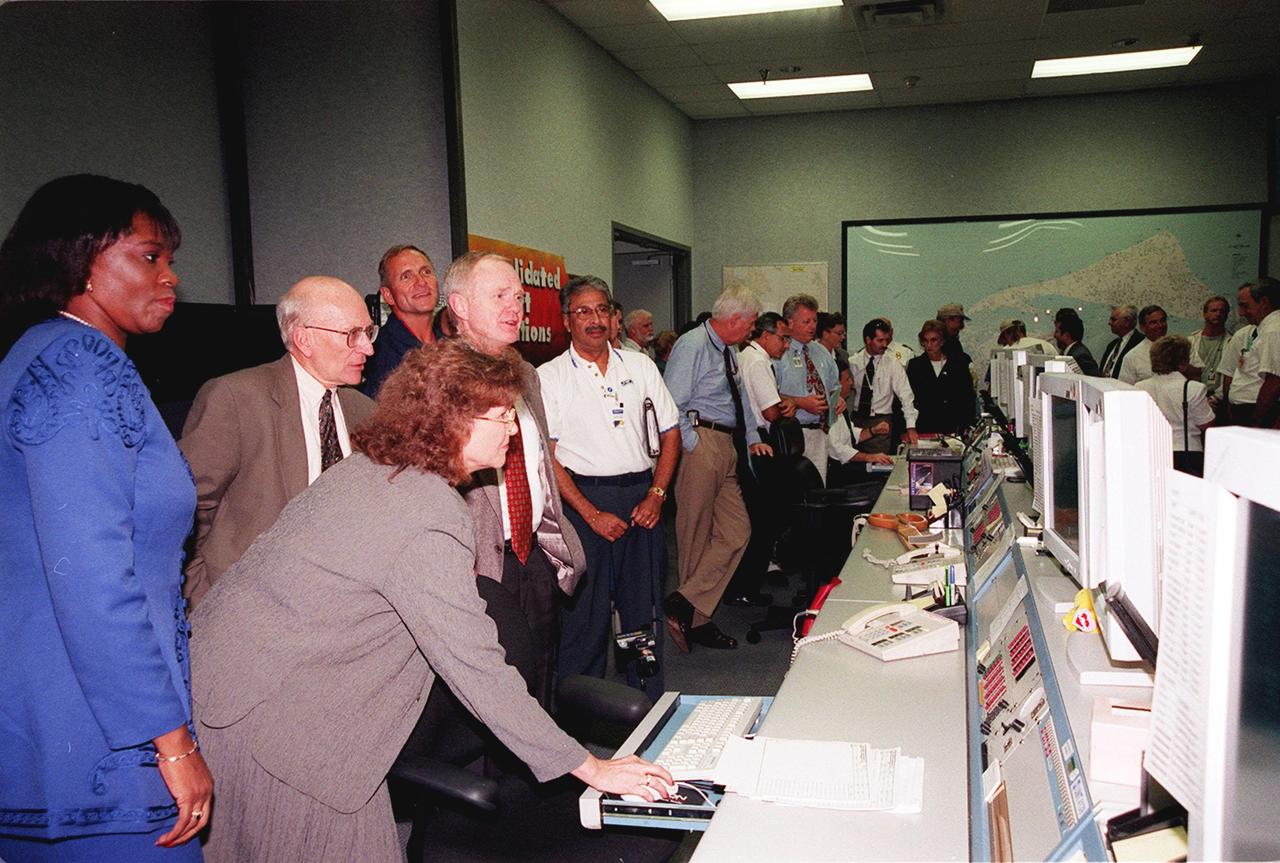
After the ribbon-cutting opening the Consolidated Support Operations Center at ROCC, Cape Canaveral Air Station, guests look at information on the computer screen during a demonstration. Among those standing are (left to right) Barbara White, supervisor, Mission Support; Ed Gormel, executive director, Joint Performance Management Office; KSC Center Director Roy Bridges; and Sam Gutierrez (white shirt), Human Resources, Space Gateway Support

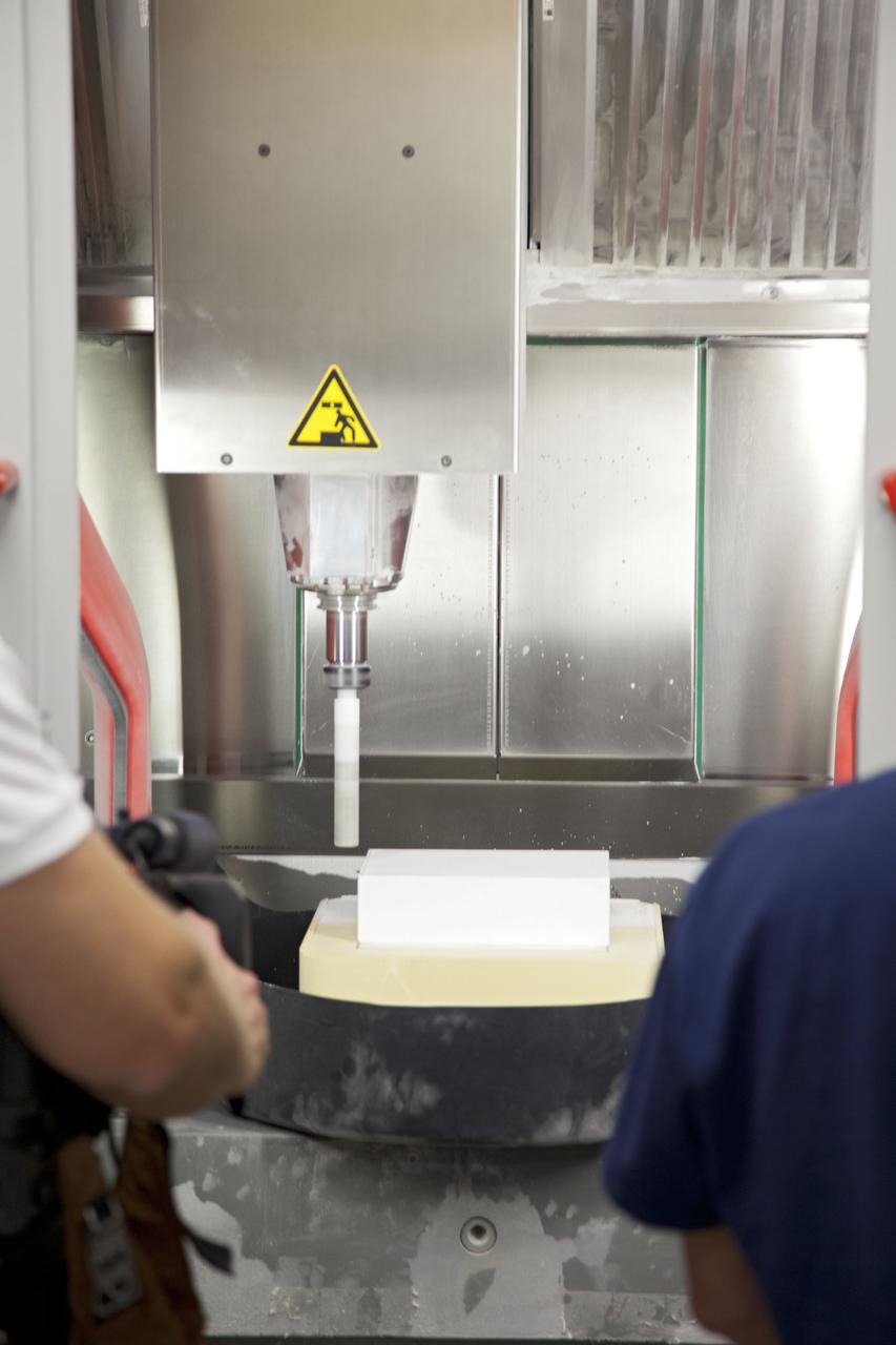
CAPE CANAVERAL, Fla. -- The heat shield tiles that will be installed to the backshell of the Orion Multi-Purpose Crew Vehicle's Exploration Flight Test EFT-1 capsule are manufactured inside the Thermal Protection System Facility at NASA's Kennedy Space Center in Florida. The insulation includes thermal barriers that are used around hatches, thrusters and other open areas of the backshell to protect the joints from heat. EFT-1 will be used during Orion's first test flight in space. For more information, visit www.nasa.gov/orion. Photo credit: Frankie Martin
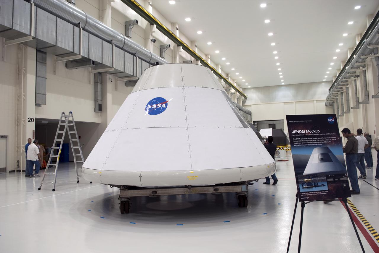
CAPE CANAVERAL, Fla. – In the Operations and Checkout Building at NASA's Kennedy Space Center in Florida, Joint Extravehicular NBL ORION Mockup, or JENOM, is on display. The mock-up details the interior components of the vehicle including seat layout and the subsystem components on the outside of the pressure vessel. Orion mock-ups also have been used to verify accessibility of the servicing locations at the launch pad and in the Vehicle Assembly Building. For information on the development of the Orion capsule, visit www.nasa.gov_orion. Photo credit: NASA_Jim Grossmann

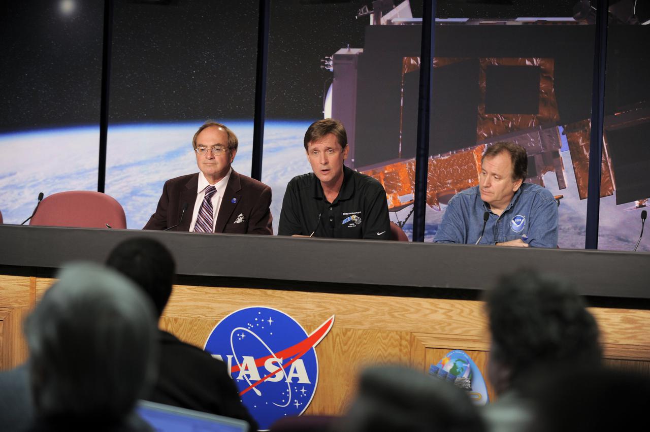
From left, Stephen Volz, assistant administrator for satellite and information services, National Oceanic and Atmospheric Administration (NOAA); Greg Mandt, GOES-R system program director, NOAA; and Sandra Smalley, director, Joint Agency Satellite Division, NASA Headquarters, speak to members of the news media during a Geostationary Operational Environmental Satellite (GOES-R) prelaunch news conference in the Kennedy Space Center's Press Site auditorium.

CAPE CANAVERAL, Fla. -- The heat shield tiles that will be installed to the backshell of the Orion Multi-Purpose Crew Vehicle's Exploration Flight Test EFT-1 capsule are manufactured inside the Thermal Protection System Facility at NASA's Kennedy Space Center in Florida. The insulation includes thermal barriers that are used around hatches, thrusters and other open areas of the backshell to protect the joints from heat. EFT-1 will be used during Orion's first test flight in space. For more information, visit www.nasa.gov/orion. Photo credit: Frankie Martin
CAPE CANAVERAL, Fla. -- The heat shield tiles that will be installed to the backshell of the Orion Multi-Purpose Crew Vehicle's Exploration Flight Test EFT-1 capsule are manufactured inside the Thermal Protection System Facility at NASA's Kennedy Space Center in Florida. The insulation includes thermal barriers that are used around hatches, thrusters and other open areas of the backshell to protect the joints from heat. EFT-1 will be used during Orion's first test flight in space. For more information, visit www.nasa.gov/orion. Photo credit: Frankie Martin
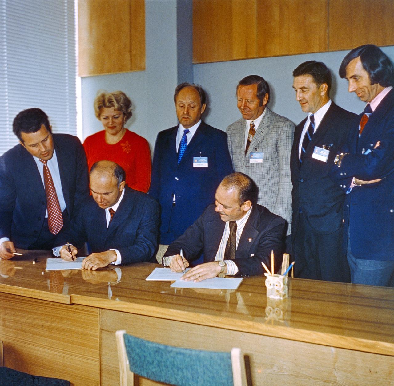
S74-29896 (September 1974) --- John P. Donnelly (seated right), NASA Assistant Administrator for Public Affairs, and Vladen S. Vereshchetin (seated left), Vice Chairman of Intercosmos, USSR Academy of Sciences, initial an agreement on information policy for the joint U.S.-USSR Apollo-Soyuz Test Project mission during ceremonies in Moscow in September 1974. Other members of the joint public affairs delegation looking on are, standing left to right, Vladimir A. Denissenko, Tatyana Klotchkovsaya, Igor P. Rumyantsev, John W. King, Nicholas Timacheff, and Robert Shafer. King is the Public Affairs Officer at the Johnson Space Center. Timacheff is the language officer with the JSC ASTP office. Shafer is NASA Deputy Assistant Administrator for Public Affairs (Television).
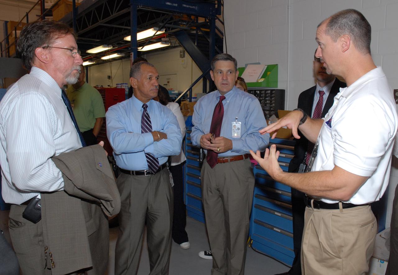
CAPE CANAVERAL, Fla. – At NASA's Kennedy Space Center in Florida, NASA Administrator Charles Bolden (third from right) is informed about Ares I-X operations in the Vehicle Assembly Building's High Bay 4. Bolden is touring several facilities at Kennedy involved with NASA's Constellation Program. Bolden also was at Kennedy for several events, including the landing of space shuttle Endeavour's STS-127 mission and the signing of the joint NASA-Japan Aerospace Exploration Agency agreement defining the terms of cooperation between the agencies on the Global Precipitation Measurement, or GPM, mission. Photo credit: NASA/Kim Shiflett

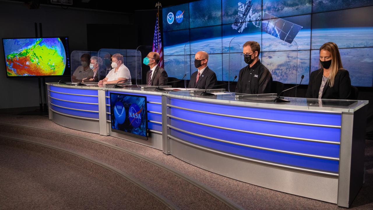
Officials from NASA, National Oceanic and Atmospheric Administration (NOAA), SpaceX participate in a prelaunch news conference on Monday, June 24, 2024, at NASA’s Kennedy Space Center in Florida for the launch of GOES-U (Geostationary Operational Environmental Satellite U) mission. From left to right, Steve Volz, assistant administrator, NOAA’s Satellite and Information Service; Pam Sullivan, director, GOES-R Program, NOAA; John Gagosian, director, Joint Agency Satellite Division; Denton Gibson, launch director, Launch Services Program, NASA; Julianna Scheiman, director, NASA Science Missions, SpaceX; Brian Cizek, launch weather officer, 45th Weather Squadron, U.S. Space Force

Officials from NASA, National Oceanic and Atmospheric Administration (NOAA), SpaceX participate in a prelaunch news conference on Monday, June 24, 2024, at NASA’s Kennedy Space Center in Florida for the launch of GOES-U (Geostationary Operational Environmental Satellite U) mission. From left to right, Steve Volz, assistant administrator, NOAA’s Satellite and Information Service; Pam Sullivan, director, GOES-R Program, NOAA; John Gagosian, director, Joint Agency Satellite Division; Denton Gibson, launch director, Launch Services Program, NASA; Julianna Scheiman, director, NASA Science Missions, SpaceX; Brian Cizek, launch weather officer, 45th Weather Squadron, U.S. Space Force
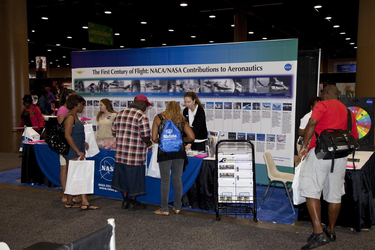
CAPE CANAVERAL, Fla. -- Education specialists at a joint exhibit from NASA's Kennedy Space Center and Glenn Research Center discuss the advancements the agency has made in aeronautics with the nationwide attendees of the Tom Joyner Family Reunion. The event was held in the Exhibit Hall of the Gaylord Palms Resort and Convention Center in Kissimmee, Fla., and hosted by nationally syndicated radio personality Tom Joyner during the extended Labor Day weekend Sept. 1-4. Besides offering attendees the opportunity to visit tourist attractions in the Orlando area, the reunion gave NASA an avenue to tout the benefits of math and scientific learning, as well as the many educational opportunities offered by the space agency. For more information on NASA's education initiatives, visit http://www.nasa.gov/education. Photo credit: NASA/Frankie Martin

CAPE CANAVERAL, Fla. -- Education specialists at a joint exhibit from NASA's Kennedy Space Center and Glenn Research Center discuss the advancements the agency has made in aeronautics with the nationwide attendees of the Tom Joyner Family Reunion. The event was held in the Exhibit Hall of the Gaylord Palms Resort and Convention Center in Kissimmee, Fla., and hosted by nationally syndicated radio personality Tom Joyner during the extended Labor Day weekend Sept. 1-4. Besides offering attendees the opportunity to visit tourist attractions in the Orlando area, the reunion gave NASA an avenue to tout the benefits of math and scientific learning, as well as the many educational opportunities offered by the space agency. For more information on NASA's education initiatives, visit http://www.nasa.gov/education. Photo credit: NASA/Frankie Martin
VANDENBERG AIR FORCE BASE, Calif. -- Participants in the prelaunch science briefing for NASA’s National Polar-orbiting Operational Environmental Satellite System Preparatory Project (NPP) spacecraft prepare to address members of the news media gathered at Vandenberg Air Force Base, Calif. Panelists are, from left, George Diller, NASA launch commentator, Jim Gleason, NPP project scientist, Goddard Space Flight Center, Greenbelt, Md., and Mitch Goldberg, NOAA Joint Polar Satellite System program scientist, Silver Spring, Md. NPP represents a critical first step in building the next-generation of Earth-observing satellites. NPP will carry the first of the new sensors developed for this satellite fleet, now known as the Joint Polar Satellite System (JPSS), to be launched in 2016. NPP is the bridge between NASA's Earth Observing System (EOS) satellites and the forthcoming series of JPSS satellites. The mission will test key technologies and instruments for the JPSS missions. NPP is targeted to launch Oct. 28 from Space Launch Complex-2 aboard a United Launch Alliance Delta II rocket. For more information, visit http:__www.nasa.gov_NPP. Photo credit: NASA_VAFB
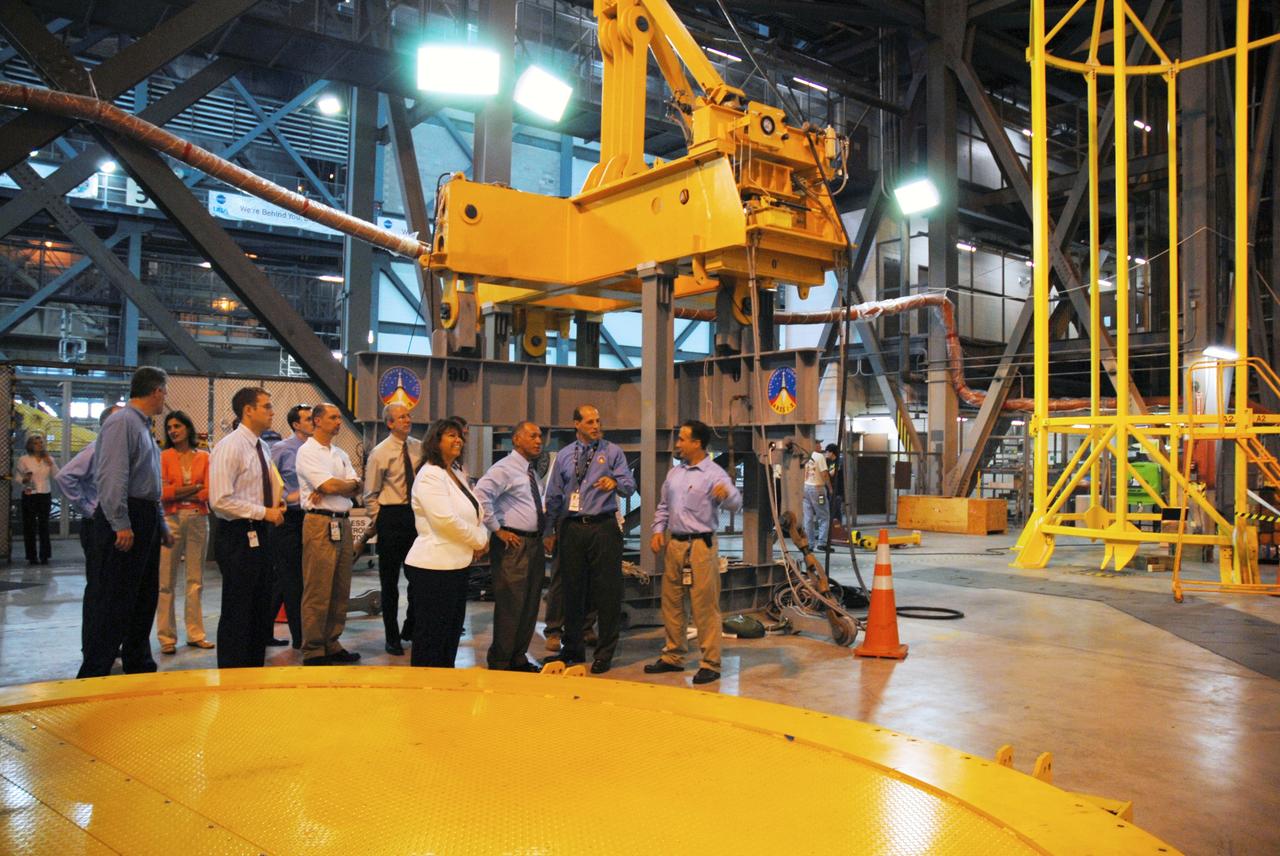
CAPE CANAVERAL, Fla. – In the Launch Equipment Test Facility at NASA's Kennedy Space Center in Florida, NASA Administrator Charles Bolden (second from left) gets information from Director of the Constellation Projects Office Pepper Phillips after the umbilical demonstration for Constellation test equipment. At left is Acting Associate Administrator of Exploration Systems Doug Cook; at right of Bolden is Center Director Bob Cabana. Bolden is touring several facilities at Kennedy involved with NASA's Constellation Program. Bolden also was at Kennedy for several events, including the landing of space shuttle Endeavour's STS-127 mission and the signing of the joint NASA-Japan Aerospace Exploration Agency agreement defining the terms of cooperation between the agencies on the Global Precipitation Measurement, or GPM, mission. Photo credit: NASA/Kim Shiflett
CAPE CANAVERAL, Fla. -- In the Vehicle Assembly Building at NASA's Kennedy Space Center in Florida, a technician is applying HD calcium grease to the field joint along the base of the left forward center solid rocket booster segment to inhibit rust and corrosion from occurring in the area. The booster along with its twin will be stacked on the mobile launcher platform along with an external fuel tank awaiting the arrival of space shuttle Endeavour for its flight to the International Space Station. As the final planned mission of the Space Shuttle Program, Endeavour and its crew will deliver the Alpha Magnetic Spectrometer, as well as critical spare components to the station on the STS-134 mission targeted for launch Feb. 26, 2011. For more information visit, http://www.nasa.gov/mission_pages/shuttle/shuttlemissions/sts134/index.html. Photo credit: NASA/Kim Shiflett

VANDENBERG AIR FORCE BASE, Calif. -- Tim Dunn, NASA launch director, Kennedy Space Center, Fla., participates in the prelaunch news conference at Vandenberg Air Force Base, Calif., for NASA’s National Polar-orbiting Operational Environmental Satellite System Preparatory Project (NPP) spacecraft. NPP represents a critical first step in building the next-generation of Earth-observing satellites. NPP will carry the first of the new sensors developed for this satellite fleet, now known as the Joint Polar Satellite System (JPSS), to be launched in 2016. NPP is the bridge between NASA's Earth Observing System (EOS) satellites and the forthcoming series of JPSS satellites. The mission will test key technologies and instruments for the JPSS missions. NPP is targeted to launch Oct. 28 from Space Launch Complex-2 aboard a United Launch Alliance Delta II rocket. For more information, visit http://www.nasa.gov/NPP. Photo credit: NASA/VAFB
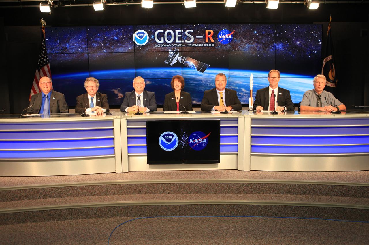
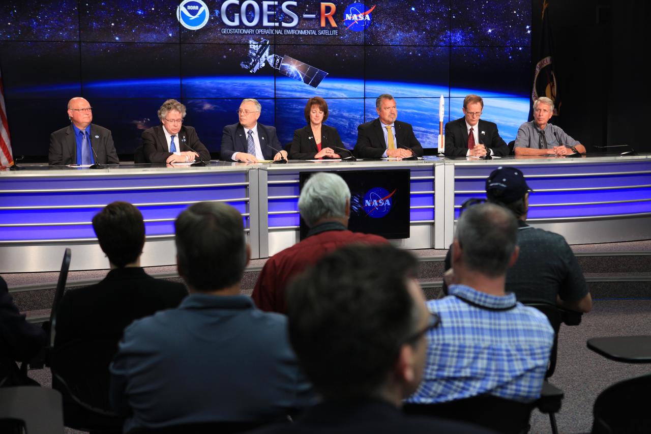
NASA and industry leaders participate in a Geostationary Operational Environmental Satellite (GOES-R), prelaunch news conference in the Kennedy Space Center's Press Site auditorium in Florida. NASA and industry leaders include: Michael Curie, of NASA Communications; Stephen Volz, assistant administrator for satellite and information services, National Oceanic and Atmospheric Administration (NOAA's); Greg Mandt, GOES-R system program director, NOAA; Sandra Smalley, director, Joint Agency Satellite Division, NASA Headquarters; Omar Baez, launch director, NASA Kennedy; Scott Messer, program manager, NASA Missions, United Launch Alliance; and Clay Flinn, launch weather officer, 4th Weather Squadron, Cape Canaveral Air Force Station.
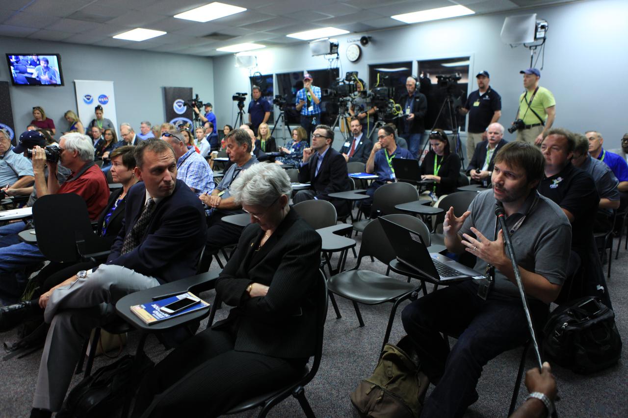
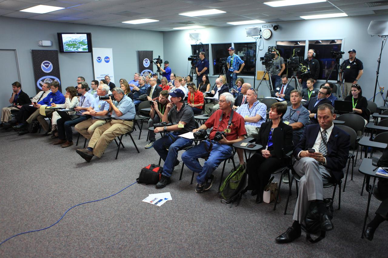
Members of the news media attend a Geostationary Operational Environmental Satellite (GOES-R) prelaunch news conference in the Kennedy Space Center's Press Site auditorium in Florida. NASA and industry leaders include: Michael Curie, of NASA Communications; Stephen Volz, assistant administrator for satellite and information services, National Oceanic and Atmospheric Administration (NOAA's); Greg Mandt, GOES-R system program director, NOAA; Sandra Smalley, director, Joint Agency Satellite Division, NASA Headquarters; Omar Baez, launch director, NASA Kennedy; Scott Messer, program manager, NASA Missions, United Launch Alliance; and Clay Flinn, launch weather officer, 4th Weather Squadron, Cape Canaveral Air Force Station.
VANDENBERG AIR FORCE BASE, Calif. -- Ken Schwer, NPP project manager, Goddard Space Flight Center, Greenbelt, Md., participates in the prelaunch news conference at Vandenberg Air Force Base, Calif., for NASA’s National Polar-orbiting Operational Environmental Satellite System Preparatory Project (NPP) spacecraft. NPP represents a critical first step in building the next-generation of Earth-observing satellites. NPP will carry the first of the new sensors developed for this satellite fleet, now known as the Joint Polar Satellite System (JPSS), to be launched in 2016. NPP is the bridge between NASA's Earth Observing System (EOS) satellites and the forthcoming series of JPSS satellites. The mission will test key technologies and instruments for the JPSS missions. NPP is targeted to launch Oct. 28 from Space Launch Complex-2 aboard a United Launch Alliance Delta II rocket. For more information, visit http://www.nasa.gov/NPP. Photo credit: NASA/VAFB
Members of the news media attend a Geostationary Operational Environmental Satellite (GOES-R) prelaunch news conference in the Kennedy Space Center's Press Site auditorium in Florida. NASA and industry leaders include: Michael Curie, of NASA Communications; Stephen Volz, assistant administrator for satellite and information services, National Oceanic and Atmospheric Administration (NOAA's); Greg Mandt, GOES-R system program director, NOAA; Sandra Smalley, director, Joint Agency Satellite Division, NASA Headquarters; Omar Baez, launch director, NASA Kennedy; Scott Messer, program manager, NASA Missions, United Launch Alliance; and Clay Flinn, launch weather officer, 4th Weather Squadron, Cape Canaveral Air Force Station.
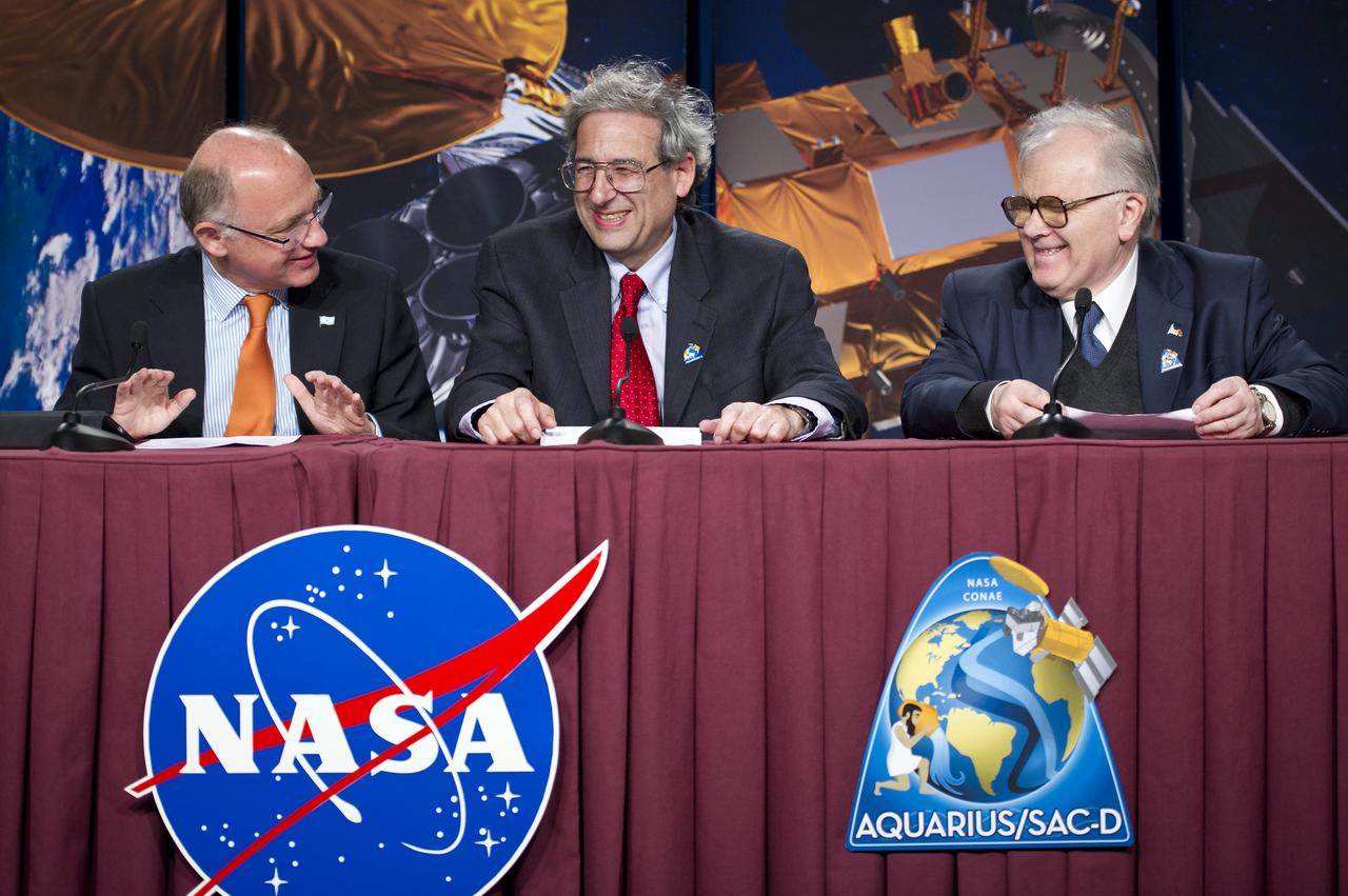
Hector Timerman, Foreign Minister of Argentina, Buenos Aires, left, Michael Freilich, NASA Earth Science Division Director, NASA Headquarters, Washington, center, and Conrado Varotto, CONAE Executive and Technical Director, Buenos Aires, laugh at the start of the Aquarius/SAC-D post-launch press conference on Friday, June 10, 2011 at the NASA Resident Office, Vandenberg Air Force Base, Calif. The joint U.S./Argentinian Aquarius/Satélite de Aplicaciones Científicas (SAC)-D mission, launched earlier on Friday June 10, will map the salinity at the ocean surface, information critical to improving our understanding of two major components of Earth's climate system: the water cycle and ocean circulation. Photo Credit: (NASA/Bill Ingalls)
NASA and industry leaders participate in a Geostationary Operational Environmental Satellite (GOES-R), prelaunch news conference in the Kennedy Space Center's Press Site auditorium in Florida. NASA and industry leaders include: Michael Curie, of NASA Communications; Stephen Volz, assistant administrator for satellite and information services, National Oceanic and Atmospheric Administration (NOAA's); Greg Mandt, GOES-R system program director, NOAA; Sandra Smalley, director, Joint Agency Satellite Division, NASA Headquarters; Omar Baez, launch director, NASA Kennedy; Scott Messer, program manager, NASA Missions, United Launch Alliance; and Clay Flinn, launch weather officer, 4th Weather Squadron, Cape Canaveral Air Force Station.
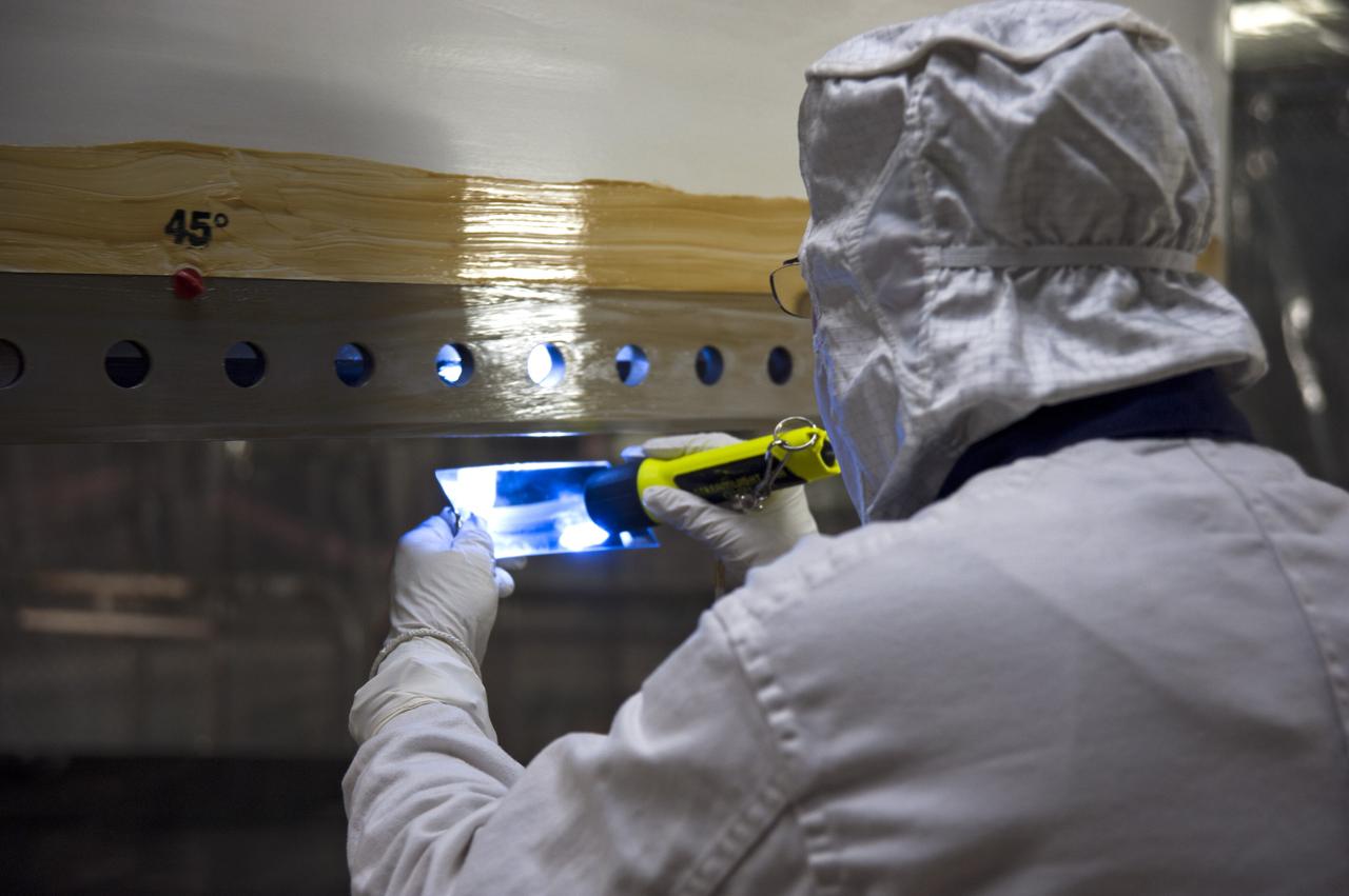
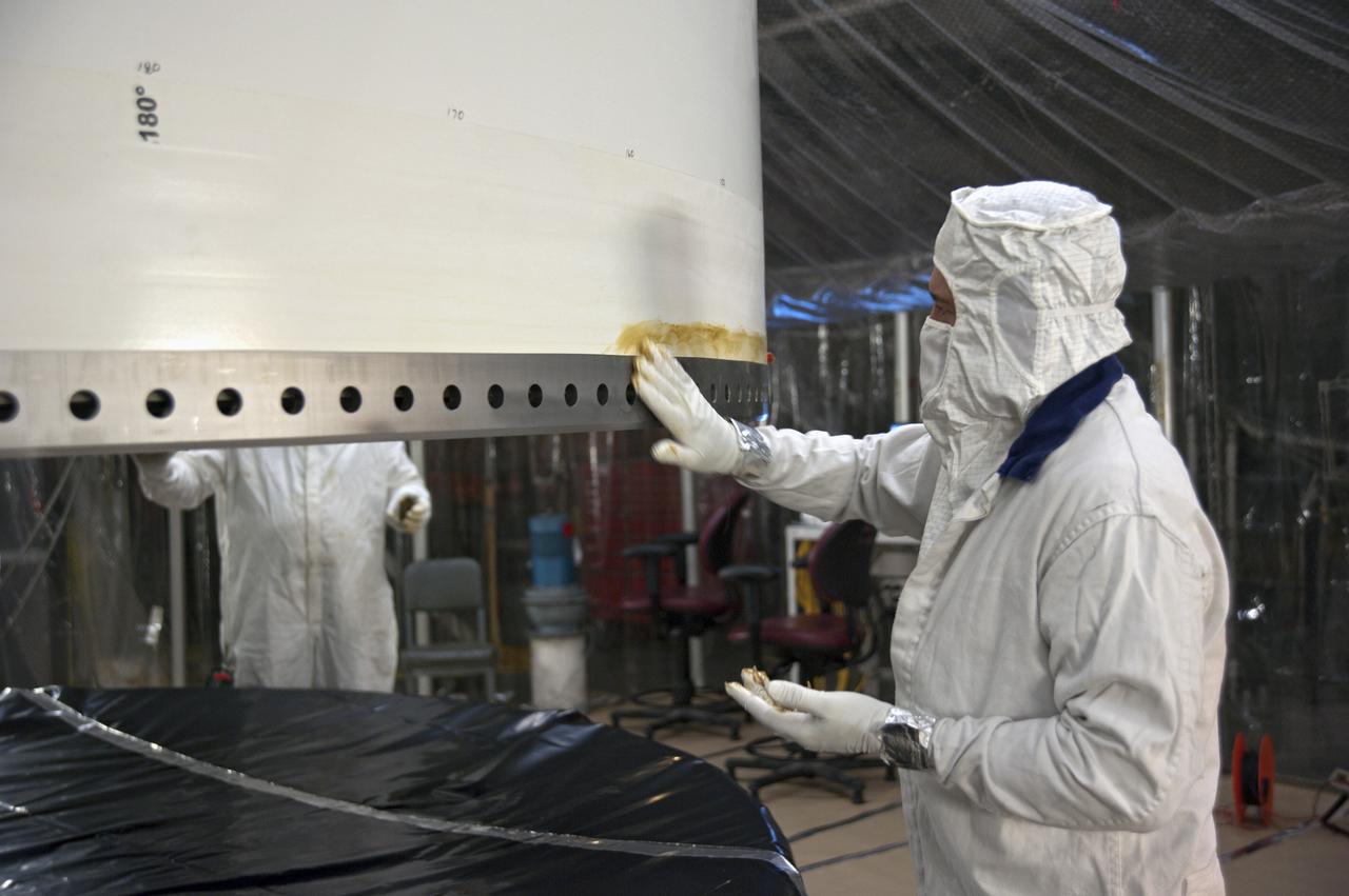
CAPE CANAVERAL, Fla. -- In the Vehicle Assembly Building at NASA's Kennedy Space Center in Florida, an inspection is being performed on the bare metal parts of the "tang" end of the segment. The tang mates with the "clevis" and creates a field joint where each segment is put together. Grease has been coated on the bare steel to inhibit rust and corrosion. The booster along with its twin will be stacked on the mobile launcher platform along with an external fuel tank awaiting the arrival of space shuttle Endeavour for its flight to the International Space Station. As the final planned mission of the Space Shuttle Program, Endeavour and its crew will deliver the Alpha Magnetic Spectrometer, as well as critical spare components to the station on the STS-134 mission targeted for launch Feb. 26, 2011. For more information visit, http://www.nasa.gov/mission_pages/shuttle/shuttlemissions/sts134/index.html. Photo credit: NASA/Kim Shiflett
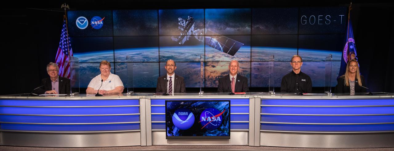
A prelaunch news conference for the National Oceanic and Atmospheric Administration’s (NOAA) Geostationary Operational Environmental Satellite-T (GOES-T) is held on Feb. 26, 2022, at NASA’s Kennedy Space Center in Florida. Participating, from left are Steve Volz, assistant administrator for Satellite and Information Services, NOAA; Pam Sullivan, director, GOES-R Program, NOAA; John Gagosian, director, Joint Agency Satellite Division, NASA Headquarters Science Mission Directorate; Tim Dunn, launch director, NASA’s Launch Services Program, Kennedy Space Center; Scott Messer, program manager, NASA Launch Services, United Launch Alliance; and Jessica Williams, launch weather officer, 45th Weather Squadron, Space Launch Delta 45. GOES-T is scheduled to lift off on a United Launch Alliance Atlas V 541 rocket from Space Launch Complex 41 at Cape Canaveral Space Force Station in Florida on March 1, 2022, at 4:38 p.m. GOES-T is the third satellite in the GOES-R series that will continue to help meteorologists observe and predict local weather events that affect public safety. The launch is being managed by NASA’s Launch Services Program based at Kennedy Space Center in Florida, America’s multi-user spaceport.
A prelaunch news conference for the National Oceanic and Atmospheric Administration’s (NOAA) Geostationary Operational Environmental Satellite-T (GOES-T) is held on Feb. 26, 2022, at NASA’s Kennedy Space Center in Florida. Participating, from left are Jasmine Hopkins, moderator, NASA Communications; Steve Volz, assistant administrator for Satellite and Information Services, NOAA; Pam Sullivan, director, GOES-R Program, NOAA; John Gagosian, director, Joint Agency Satellite Division, NASA Headquarters Science Mission Directorate; Tim Dunn, launch director, NASA’s Launch Services Program, Kennedy Space Center; Scott Messer, program manager, NASA Launch Services, United Launch Alliance; and Jessica Williams, launch weather officer, 45th Weather Squadron, Space Launch Delta 45. GOES-T is scheduled to lift off on a United Launch Alliance Atlas V 541 rocket from Space Launch Complex 41 at Cape Canaveral Space Force Station in Florida on March 1, 2022, at 4:38 p.m. GOES-T is the third satellite in the GOES-R series that will continue to help meteorologists observe and predict local weather events that affect public safety. The launch is being managed by NASA’s Launch Services Program based at Kennedy Space Center in Florida, America’s multi-user spaceport.
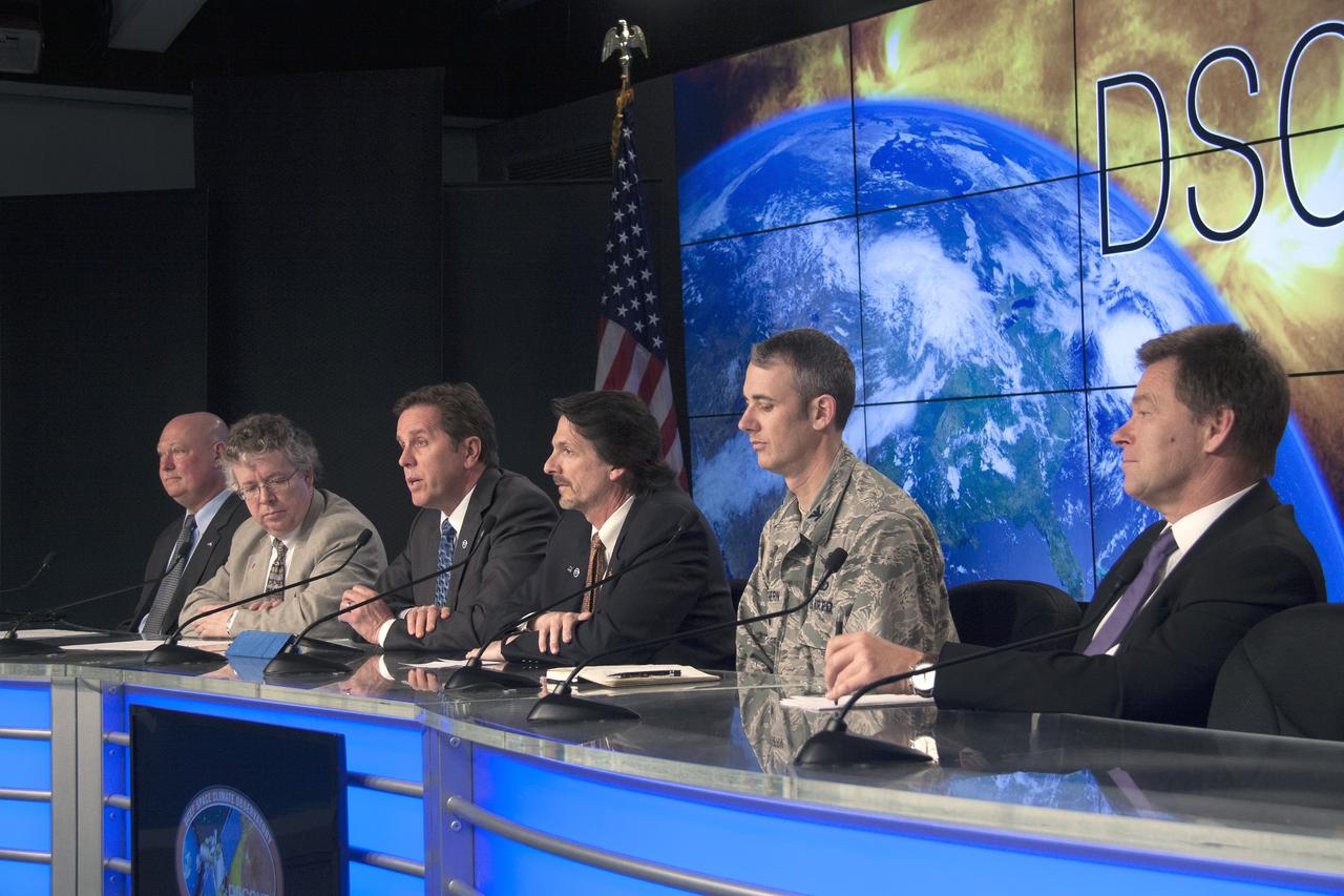
CAPE CANAVERAL, Fla. – A prelaunch briefing at NASA’s Kennedy Space Center in Florida brings media up to date on preparations for the liftoff of NOAA’s Deep Space Climate Observatory spacecraft, or DSCOVR. From left are Michael Curie, moderator, NASA Public Affairs, Stephen Volz, assistant administrator of the NOAA Satellite and Information Service, Tom Berger, director of the NOAA Space Weather Prediction Center, Steven Clarke, NASA Joint Agency Satellite Division director for the agency’s Science Mission Directorate, Col. D. Jason Cothern, Space Demonstrations Division chief at Kirtland Air Force Base in Albuquerque, New Mexico, and Hans Koenigsmann, vice president of mission assurance at SpaceX. DSCOVR will launch aboard a SpaceX Falcon 9 rocket. The mission is a partnership between NOAA, NASA and the U.S. Air Force. DSCOVR will maintain the nation's real-time solar wind monitoring capabilities which are critical to the accuracy and lead time of NOAA's space weather alerts and forecasts. To learn more about DSCOVR, visit http://www.nesdis.noaa.gov/DSCOVR. Photo credit: NASA/Jim Grossman
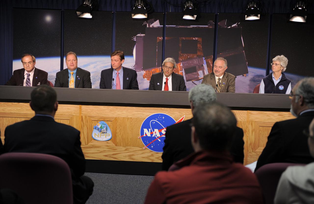
VANDENBERG AIR FORCE BASE, Calif. -- At Vandenberg Air Force Base in California, NASA and NOAA managers participate in a news briefing following the successful launch of NASA's National Polar-orbiting Operational Environmental Satellite System Preparatory Project (NPP) aboard a United Launch Alliance Delta II rocket. From left are George Diller, NASA Public Affairs; Ken Schwer, NPP project manager, NASA's Goddard Space Flight Center; Jim Gleason, NPP project scientist, NASA's Goddard Space Flight Center; Mike Frielich, director, NASA Earth Science Division; Charles Gay, acting associate administrator, NASA Mission Directorate; and Mary Glackin, deputy undersecretary for Operations, National Oceanic and Atmospheric Administration. Launch was at 2:48 a.m. PDT. NPP represents a critical first step in building the next-generation of Earth-observing satellites. NPP will carry the first of the new sensors developed for this satellite fleet, now known as the Joint Polar Satellite System (JPSS) to be launched in 2016. NPP is the bridge between NASA's Earth Observing System (EOS) satellites and the forthcoming series of JPSS satellites. The mission will test key technologies and instruments for the JPSS missions. For more information, visit http:__www.nasa.gov_NPP. Photo credit: NASA_Kim Shiflett
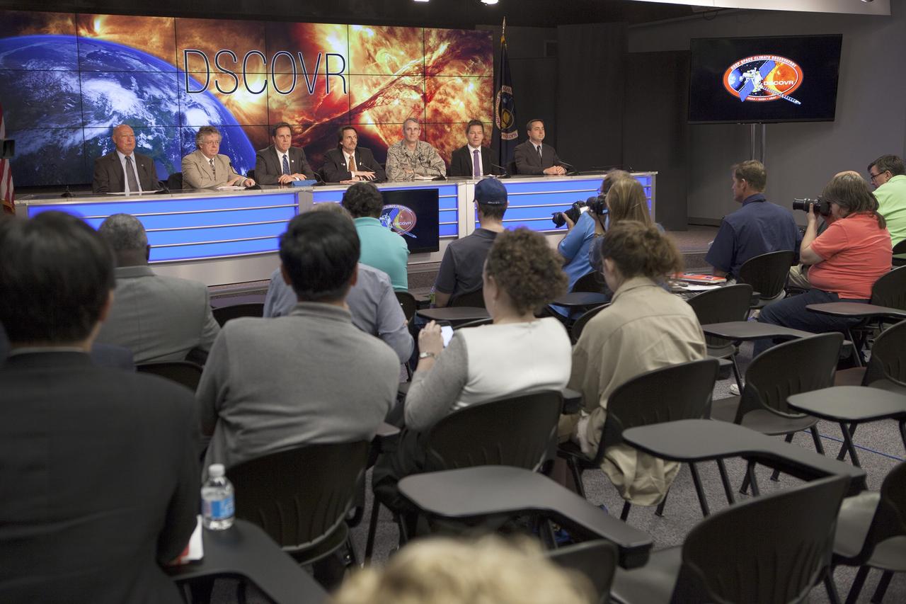
CAPE CANAVERAL, Fla. – A prelaunch briefing at NASA’s Kennedy Space Center in Florida brings media up to date on preparations for the liftoff of NOAA’s Deep Space Climate Observatory spacecraft, or DSCOVR. From left are Michael Curie, moderator, NASA Public Affairs, Stephen Volz, assistant administrator of the NOAA Satellite and Information Service, Tom Berger, director of the NOAA Space Weather Prediction Center, Steven Clarke, NASA Joint Agency Satellite Division director for the agency’s Science Mission Directorate, Col. D. Jason Cothern, Space Demonstrations Division chief at Kirtland Air Force Base in Albuquerque, New Mexico, and Hans Koenigsmann, vice president of mission assurance at SpaceX, and Mike McAleenan, launch weather officer with the U.S. Air Force 45th Weather Squadron. DSCOVR will launch aboard a SpaceX Falcon 9 rocket. The mission is a partnership between NOAA, NASA and the U.S. Air Force. DSCOVR will maintain the nation's real-time solar wind monitoring capabilities which are critical to the accuracy and lead time of NOAA's space weather alerts and forecasts. To learn more about DSCOVR, visit http://www.nesdis.noaa.gov/DSCOVR. Photo credit: NASA/Kim Shiflett
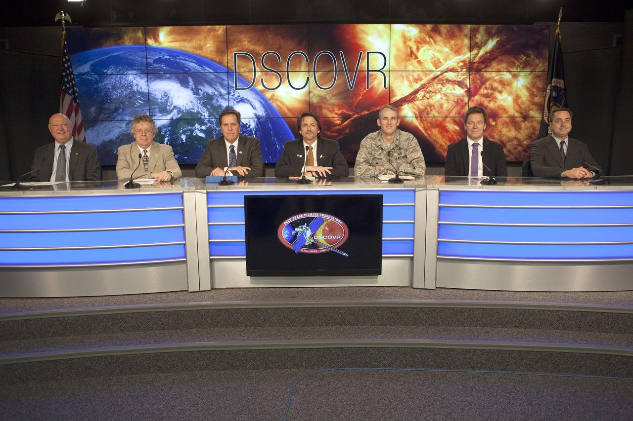
CAPE CANAVERAL, Fla. – Launch and mission officials prepare for the start of a prelaunch briefing at NASA’s Kennedy Space Center in Florida regarding NOAA’s Deep Space Climate Observatory mission, or DSCOVR. From left are Michael Curie, moderator, NASA Public Affairs, Stephen Volz, assistant administrator of the NOAA Satellite and Information Service, Tom Berger, director of the NOAA Space Weather Prediction Center, Steven Clarke, NASA Joint Agency Satellite Division director for the agency’s Science Mission Directorate, Col. D. Jason Cothern, Space Demonstrations Division chief at Kirtland Air Force Base in Albuquerque, New Mexico, and Hans Koenigsmann, vice president of mission assurance at SpaceX, and Mike McAleenan, launch weather officer with the U.S. Air Force 45th Weather Squadron. DSCOVR will launch aboard a SpaceX Falcon 9 rocket. The mission is a partnership between NOAA, NASA and the U.S. Air Force. DSCOVR will maintain the nation's real-time solar wind monitoring capabilities which are critical to the accuracy and lead time of NOAA's space weather alerts and forecasts. To learn more about DSCOVR, visit http://www.nesdis.noaa.gov/DSCOVR. Photo credit: NASA/Kim Shiflett

A Mod-0A 200-kilowatt wind turbine designed by National Aeronautics and Space Administration (NASA) Lewis Research Center and constructed in Block Island, Rhode Island. The wind turbine program was a joint program between NASA and the Energy Research and Development Administration (ERDA) during the 1970s to develop less expensive forms of energy. NASA Lewis was assigned the responsibility of developing large horizontal-axis wind turbines. The program included a series of increasingly powerful wind turbines, designated: Mod-0A, Mod-1, WTS-4, and Mod-5. The program’s first device was a Mod-0 100-kilowatt wind turbine test bed at NASA’s Plum Brook Station. This Mod-0A 200-kilowatt turbine, completed in 1977, was the program’s second-generation device. It included a 125-foot diameter blade atop a 100-foot tall tower. This early wind turbine was designed determine its operating problems, integrate with the local utilities, and assess the attitude of the local community. There were additional Mod-0A turbines built in Culebra, Puerto Rico; Clayton, New Mexico; and Oahu, Hawaii. The Mod-0A turbines suffered durability issues with the rotor blade and initially appeared unreliable. NASA engineers addressed the problems, and the turbines proved to be reliable and efficient devices that operated for a number of years. The information gained from these early models was vital to the design and improvement of the later generations.
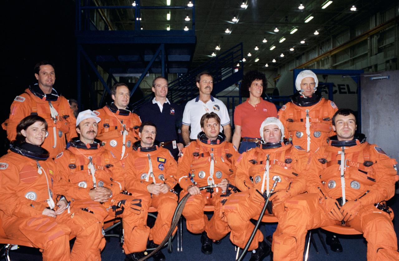
S94-47050 (28 Oct 1994) --- Crew members for the joint Space Shuttle/Russian Mir Space Station missions assemble for an informal portrait during a break in training in the Systems Integration Facility at the Johnson Space Center (JSC). In front (left to right) are astronaut Bonnie J. Dunbar; cosmonauts Aleksandr F. Poleshchuk, Yuriy I. Onufriyenko, Gennadiy M. Strekalov and Vladimir N. Dezhurov. In the rear are astronaut Gregory J. Harbaugh; cosmonaut Anatoliy Y. Solovyev, and astronauts Charles J. Precourt, Robert L. Gibson, Ellen S. Baker and Norman E. Thagard. In a precedent-setting flight, Thagard will be launched as a guest researcher along with Dezhurov, commander, and Strekalov, flight engineer, to Russia's Mir Space Station early next year for a three month mission, designated as Mir 18. Then in late spring, as the assignment of STS-71, the Space Shuttle Atlantis will rendezvous with Mir to pick up the Mir 18 crew and transfer cosmonauts Solovyov and Nikolai M. Budarin to the station for the Mir 19 mission. STS-71 mission specialist Dunbar is training as Thagard's backup.
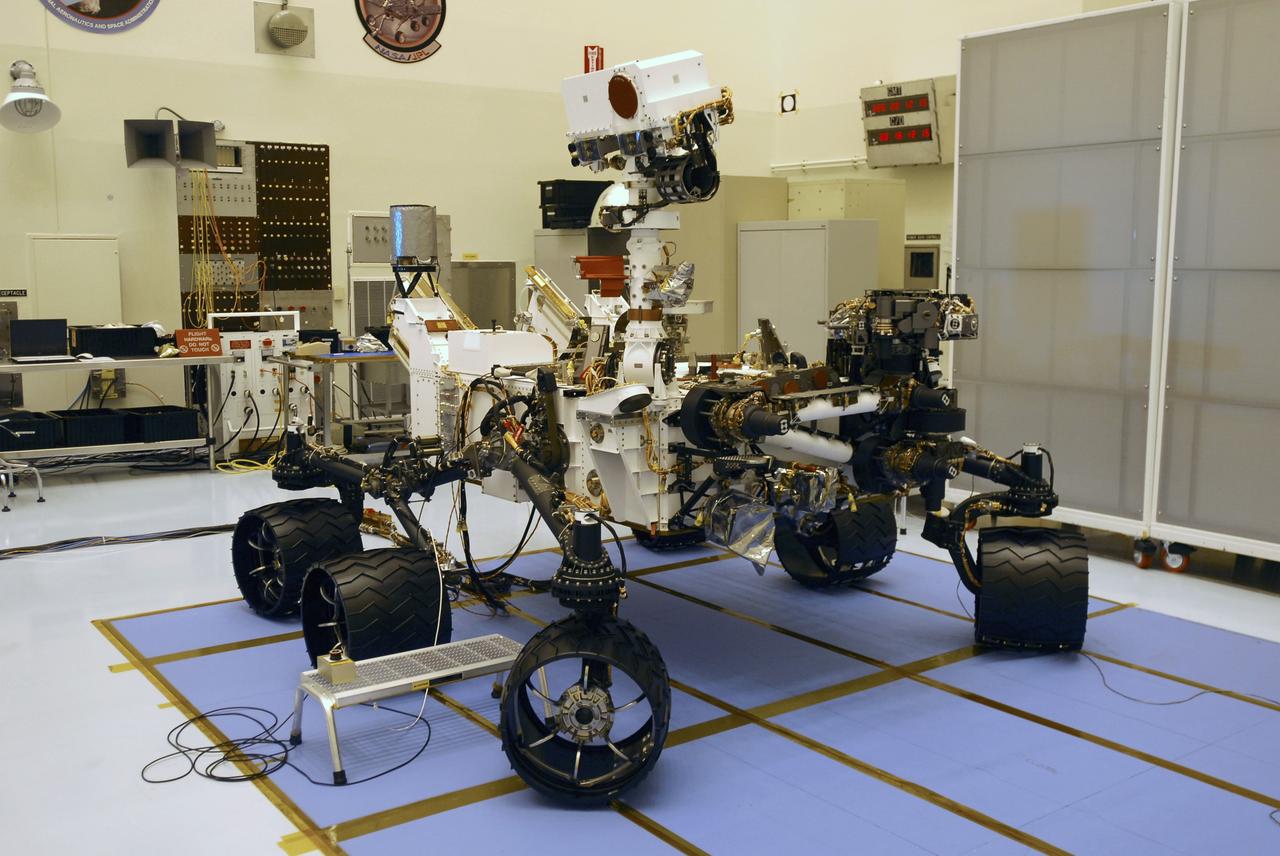
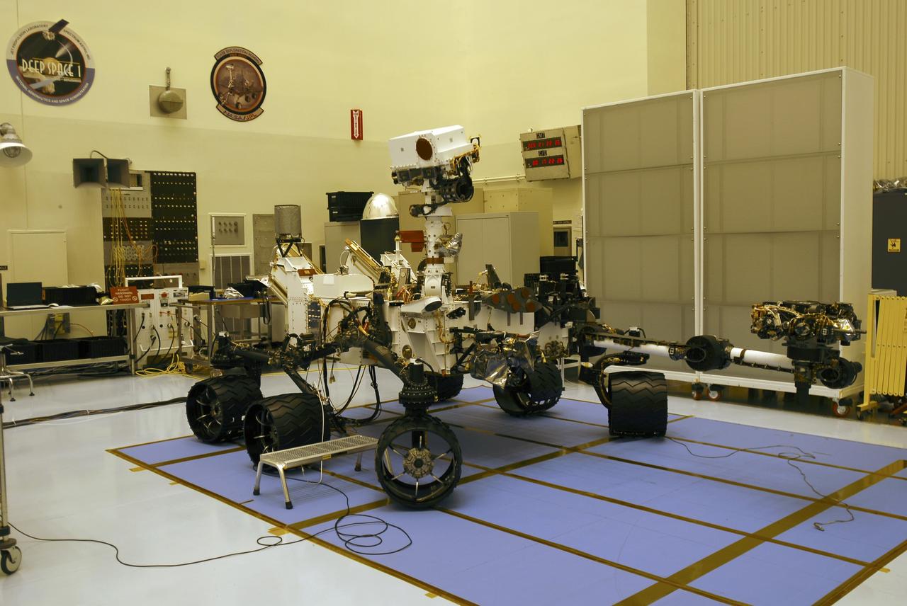
CAPE CANAVERAL, Fla. -- In the Payload Hazardous Servicing Facility at NASA's Kennedy Space Center in Florida, the robotic arm of the Mars Science Laboratory (MSL) rover, Curiosity, has been stowed against the body of the spacecraft. The arm will hold and maneuver instruments that will help scientists analyze Martian rocks and soil. Much like a human arm, the robotic arm has flexibility through shoulder, elbow, and wrist joints that permit the arm to extend, bend, and angle precisely against rocks and soil to grind away layers, take microscopic images and analyze their elemental composition. At the end of the arm is a hand-like structure, the turret, for holding various tools that can spin through a 350-degree turning range. A United Launch Alliance Atlas V-541 configuration will be used to loft MSL into space. Curiosity’s 10 science instruments are designed to search for evidence on whether Mars has had environments favorable to microbial life, including chemical ingredients for life. The unique rover will use a laser to look inside rocks and release its gasses so that the rover’s spectrometer can analyze and send the data back to Earth. MSL is scheduled to launch Nov. 25 from Space Launch Complex 41 on Cape Canaveral Air Force Station in Florida. For more information, visit http://www.nasa.gov/msl. Photo credit: NASA/Charisse Nahser

A group of Coast Guard seamen leave their ship to verify ice formations on the Great Lakes as part of an joint effort with the National Aeronautics and Space Administration (NASA) Lewis Research Center and the National Oceanic and Atmospheric Administration. The regular winter freezing of large portions of the Great Lakes stalled the shipping industry. Lewis began working on two complementary systems to monitor the ice. The Side Looking Airborne Radar (SLAR) system used microwaves to measure the ice distribution and electromagnetic systems used noise modulation to determine the thickness of the ice. The images were then transferred via satellite to the Coast Guard station. The Coast Guard then transmitted the pertinent images by VHF to the ship captains to help them select the best route. The Great Lakes ice mapping devices were first tested on NASA aircraft during the winter of 1972 and 1973. The pulsed radar system was transferred to the Coast Guard’s C-130 aircraft for the 1975 and 1976 winter. The SLAR was installed in the rear cargo door, and the small S-band antenna was mounted to the underside of the aircraft. Coast Guard flights began in January 1975 at an altitude of 11,000 feet. Early in the program, teams of guardsmen and NASA researchers frequently set out in boats to take samples and measurements of the ice in order to verify the radar information.
CAPE CANAVERAL, Fla. -- In the Payload Hazardous Servicing Facility at NASA's Kennedy Space Center in Florida, preparations are under way to stow the robotic arm on the Mars Science Laboratory (MSL) rover, Curiosity. The arm will hold and maneuver instruments that will help scientists analyze Martian rocks and soil. Much like a human arm, the robotic arm has flexibility through shoulder, elbow, and wrist joints that permit the arm to extend, bend, and angle precisely against rocks and soil to grind away layers, take microscopic images and analyze their elemental composition. At the end of the arm is a hand-like structure, the turret, for holding various tools that can spin through a 350-degree turning range. A United Launch Alliance Atlas V-541 configuration will be used to loft MSL into space. Curiosity’s 10 science instruments are designed to search for evidence on whether Mars has had environments favorable to microbial life, including chemical ingredients for life. The unique rover will use a laser to look inside rocks and release its gasses so that the rover’s spectrometer can analyze and send the data back to Earth. MSL is scheduled to launch Nov. 25 from Space Launch Complex 41 on Cape Canaveral Air Force Station in Florida. For more information, visit http://www.nasa.gov/msl. Photo credit: NASA/Charisse Nahser

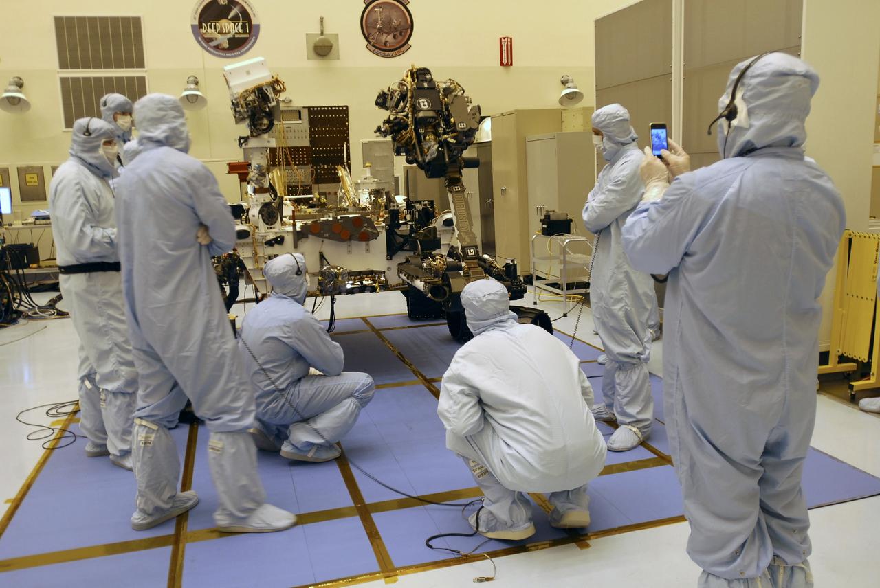
CAPE CANAVERAL, Fla. -- In the Payload Hazardous Servicing Facility at NASA's Kennedy Space Center in Florida, spacecraft technicians discuss their readiness to stow the robotic arm on the Mars Science Laboratory (MSL) rover, Curiosity. The arm will hold and maneuver instruments that will help scientists analyze Martian rocks and soil. Much like a human arm, the robotic arm has flexibility through shoulder, elbow, and wrist joints that permit the arm to extend, bend, and angle precisely against rocks and soil to grind away layers, take microscopic images and analyze their elemental composition. At the end of the arm is a hand-like structure, the turret, for holding various tools that can spin through a 350-degree turning range. A United Launch Alliance Atlas V-541 configuration will be used to loft MSL into space. Curiosity’s 10 science instruments are designed to search for evidence on whether Mars has had environments favorable to microbial life, including chemical ingredients for life. The unique rover will use a laser to look inside rocks and release its gasses so that the rover’s spectrometer can analyze and send the data back to Earth. MSL is scheduled to launch Nov. 25 from Space Launch Complex 41 on Cape Canaveral Air Force Station in Florida. For more information, visit http://www.nasa.gov/msl. Photo credit: NASA/Charisse Nahser
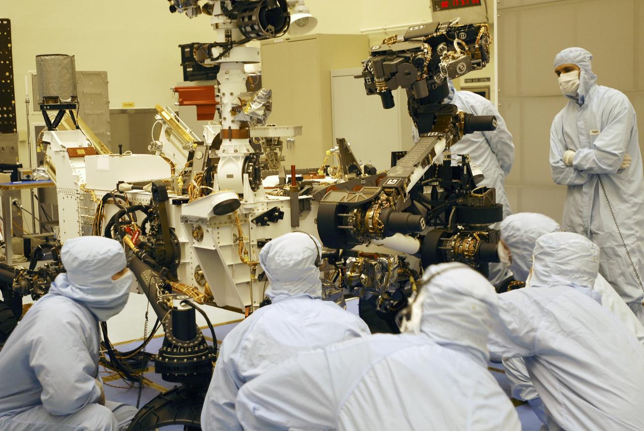
CAPE CANAVERAL, Fla. -- Under the watchful eyes of the spacecraft technicians in the Payload Hazardous Servicing Facility at NASA's Kennedy Space Center in Florida, the robotic arm of the Mars Science Laboratory (MSL) rover, Curiosity, moves into place against the body of the spacecraft. The arm will hold and maneuver instruments that will help scientists analyze Martian rocks and soil. Much like a human arm, the robotic arm has flexibility through shoulder, elbow, and wrist joints that permit the arm to extend, bend, and angle precisely against rocks and soil to grind away layers, take microscopic images and analyze their elemental composition. At the end of the arm is a hand-like structure, the turret, for holding various tools that can spin through a 350-degree turning range. A United Launch Alliance Atlas V-541 configuration will be used to loft MSL into space. Curiosity’s 10 science instruments are designed to search for evidence on whether Mars has had environments favorable to microbial life, including chemical ingredients for life. The unique rover will use a laser to look inside rocks and release its gasses so that the rover’s spectrometer can analyze and send the data back to Earth. MSL is scheduled to launch Nov. 25 from Space Launch Complex 41 on Cape Canaveral Air Force Station in Florida. For more information, visit http://www.nasa.gov/msl. Photo credit: NASA/Charisse Nahser
CAPE CANAVERAL, Fla. -- In the Payload Hazardous Servicing Facility at Kennedy Space Center in Florida, spacecraft technicians monitor the movement of the robotic arm of the Mars Science Laboratory (MSL) rover, Curiosity, as it is stowed against the body of the spacecraft. The arm will hold and maneuver instruments that will help scientists analyze Martian rocks and soil. Much like a human arm, the robotic arm has flexibility through shoulder, elbow, and wrist joints that permit the arm to extend, bend, and angle precisely against rocks and soil to grind away layers, take microscopic images and analyze their elemental composition. At the end of the arm is a hand-like structure, the turret, for holding various tools that can spin through a 350-degree turning range. A United Launch Alliance Atlas V-541 configuration will be used to loft MSL into space. Curiosity’s 10 science instruments are designed to search for evidence on whether Mars has had environments favorable to microbial life, including chemical ingredients for life. The unique rover will use a laser to look inside rocks and release its gasses so that the rover’s spectrometer can analyze and send the data back to Earth. MSL is scheduled to launch Nov. 25 from Space Launch Complex 41 on Cape Canaveral Air Force Station in Florida. For more information, visit http://www.nasa.gov/msl. Photo credit: NASA/Charisse Nahser
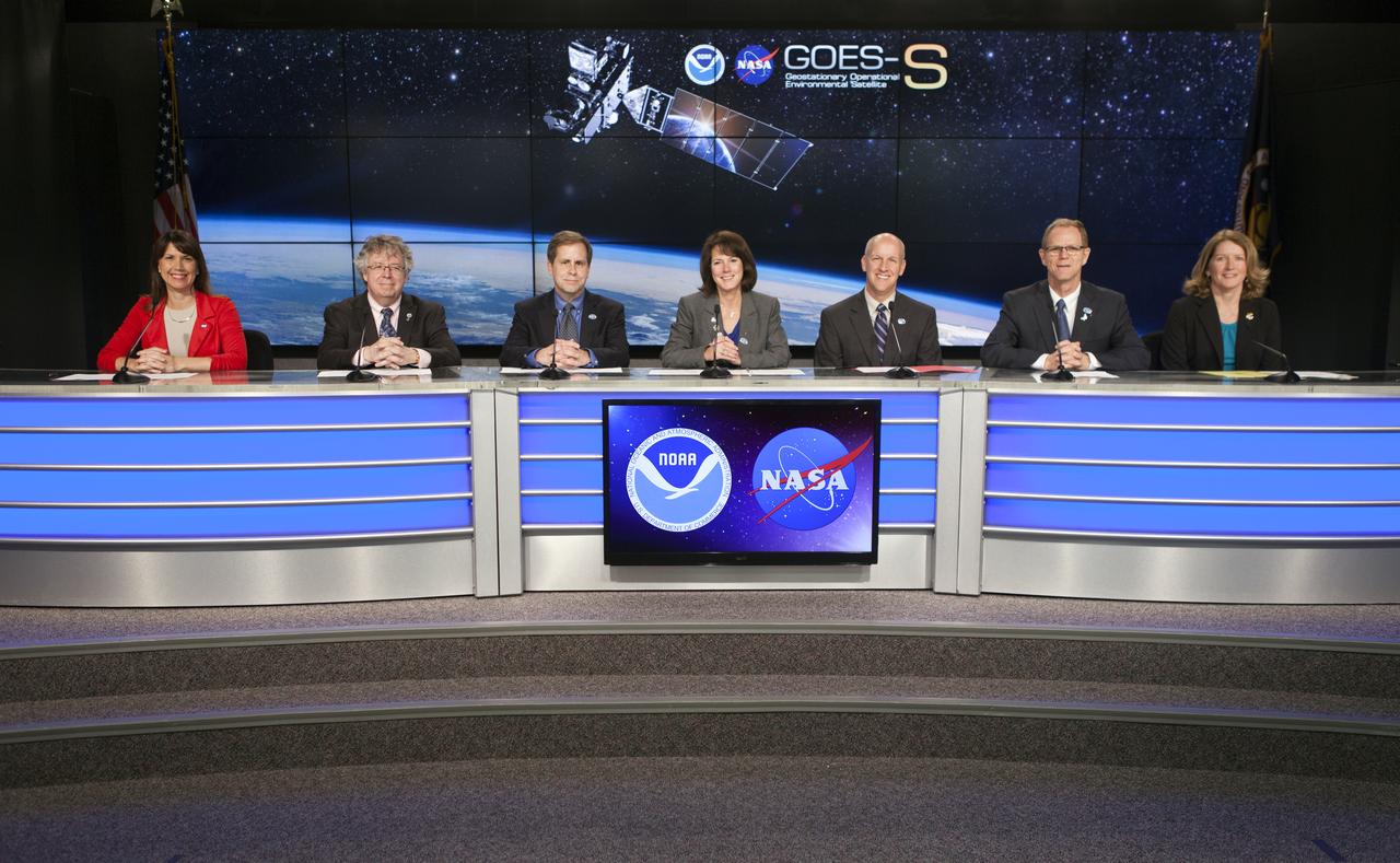
In the Kennedy Space Center's Press Site auditorium, NASA and industry leaders speak to members of the media at a prelaunch news conference about National Oceanic and Atmospheric Administration's, or NOAA's, Geostationary Operational Environmental Satellite, or GOES-S. Participants from left are: Tori McLendon of NASA Communications; Stephen Volz, director for Satellite and Information Services for NOAA; Tim Walsh, acting GOES-R System Program director for NOAA; Sandra Smalley, director of the Joint Agency Satellite Division at NASA Headquarters in Washington D.C.; Tim Dunn, NASA launch director at Kennedy; Scott Messer, manager of NASA Programs for United launch Alliance; and Kathy Winters, launch weather officer for the U.S. Air Force 45th Weather Squadron at Cape Canaveral Air Force Station. The GOES series of satellites will significantly improve the detection and observation of environmental phenomena that directly affect public safety, protection of property and the nation's economic health and prosperity. GOES-S is slated to lift off at 5:02 p.m. EST on March 1, 2018 aboard a United Launch Alliance Atlas V rocket.
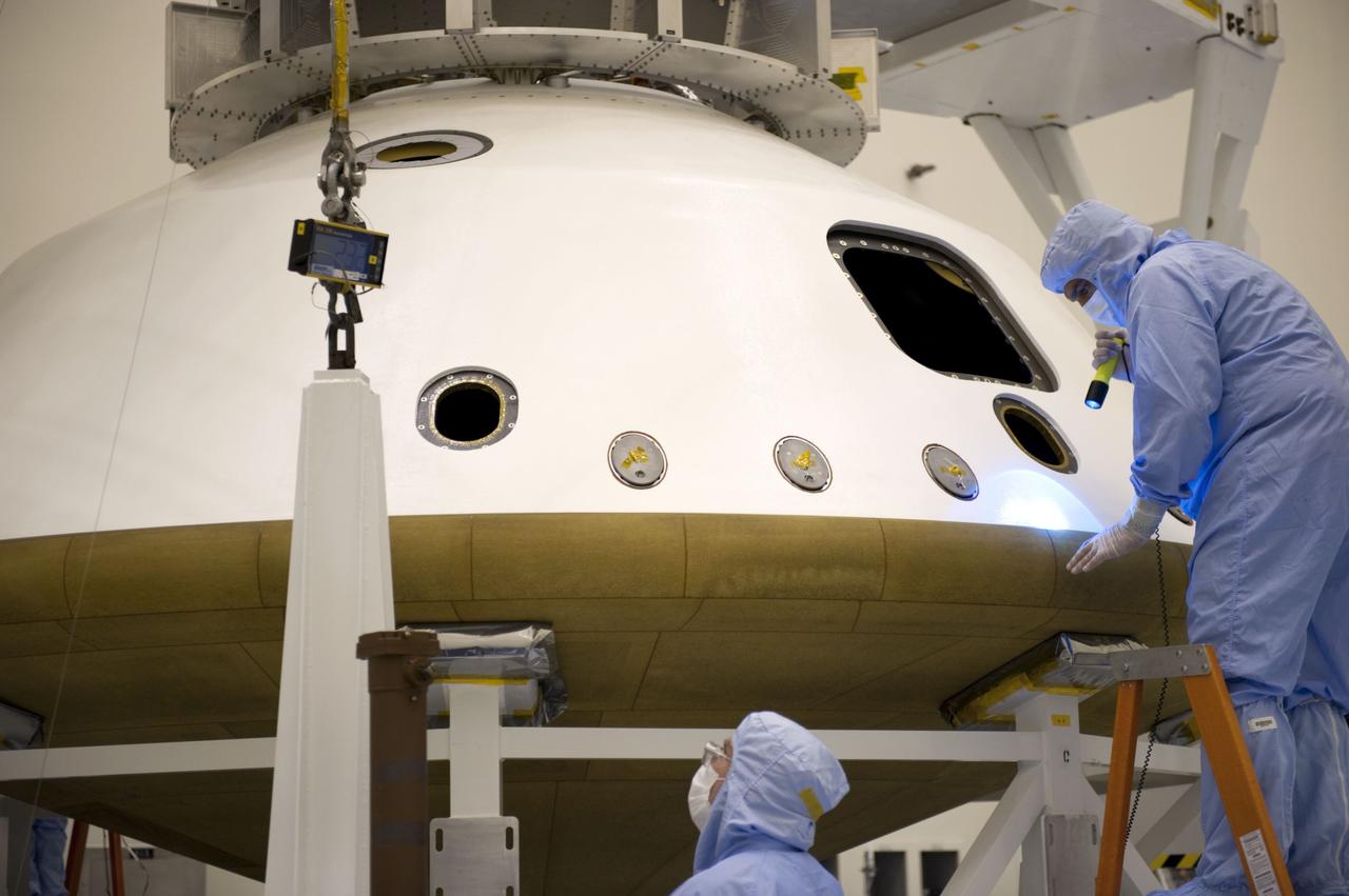
Cape Canaveral, Fla. -- At the Payload Hazardous Servicing Facility at NASA's Kennedy Space Center in Florida, technicians inspect the joint where two components of the aeroshell meet. The aeroshell is an element of NASA's Mars Science Laboratory (MSL) and consists of the spacecraft's heat shield and the backshell which carries the parachute and several components used during later stages of entry, descent and landing. MSL's components include a compact car-sized rover, Curiosity, which has 10 science instruments designed to search for evidence on whether Mars has had environments favorable to microbial life, including chemical ingredients for life. The unique rover will use a laser to look inside rocks and release its gasses so that the rover’s spectrometer can analyze and send the data back to Earth. Launch of MSL aboard a United Launch Alliance Atlas V rocket is scheduled for Nov. 25 from Space Launch Complex 41 on Cape Canaveral Air Force Station in Florida. For more information, visit http://www.nasa.gov/msl. Photo credit: NASA/Kim Shiflett
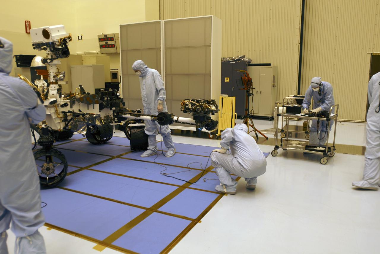
CAPE CANAVERAL, Fla. -- In the Payload Hazardous Servicing Facility at NASA's Kennedy Space Center in Florida, spacecraft technicians prepare to stow the robotic arm on the Mars Science Laboratory (MSL) rover, Curiosity. The arm will hold and maneuver instruments that will help scientists analyze Martian rocks and soil. Much like a human arm, the robotic arm has flexibility through shoulder, elbow, and wrist joints that permit the arm to extend, bend, and angle precisely against rocks and soil to grind away layers, take microscopic images and analyze their elemental composition. At the end of the arm is a hand-like structure, the turret, for holding various tools that can spin through a 350-degree turning range. A United Launch Alliance Atlas V-541 configuration will be used to loft MSL into space. Curiosity’s 10 science instruments are designed to search for evidence on whether Mars has had environments favorable to microbial life, including chemical ingredients for life. The unique rover will use a laser to look inside rocks and release its gasses so that the rover’s spectrometer can analyze and send the data back to Earth. MSL is scheduled to launch Nov. 25 from Space Launch Complex 41 on Cape Canaveral Air Force Station in Florida. For more information, visit http://www.nasa.gov/msl. Photo credit: NASA/Charisse Nahser
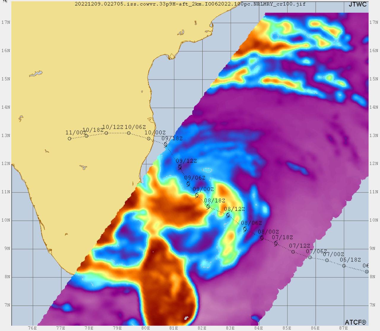
Data from two weather instruments developed at NASA's Jet Propulsion Laboratory in Southern California to provide forecasters data on weather over the open ocean were used to create this image of Tropical Cyclone Mandous on Dec. 9, 2022, as the storm approached the southeastern coast of India. Forecasters at the U.S. Joint Typhoon Warning Center in Pearl Harbor, Hawaii, used the image and others like it to understand the storm's intensity and track its path. The instruments, Compact Ocean Wind Vector Radiometer (COWVR) and Temporal Experiment for Storms and Tropical Systems (TEMPEST), observe the planet's atmosphere and surface from aboard the International Space Station. The image above uses 33.9 gigahertz microwave emissions measured from COWVR to detect structural features of Mandous, including its center, which is about 160 miles (250 kilometers) northeast of the northern tip of Sri Lanka. The colored portions over water indicate the presence of precipitation, with yellow and orange indicating where the storm is strongest, while blue shows where it's weakest. COWVR and TEMPEST sent the data for this image back to Earth in a direct stream via NASA's tracking and data relay satellite (TDRS) constellation. The data was processed at JPL, and meteorologists at the U.S. Naval Research Laboratory in Monterey, California, created the image, which they shared with the Joint Typhoon Warning Center. About the size of a minifridge, COWVR measures natural microwave emissions over the ocean. The magnitude of the emissions increases with the amount of rain in the atmosphere. TEMPEST – comparable in size to a cereal box – tracks microwaves at a much shorter wavelength, allowing it to detect atmospheric water vapor. Both microwave radiometers were conceived to demonstrate that smaller, more energy-efficient, more simply designed sensors can perform most of the same measurements as current space-based weather instruments that are heavier, consume more power, and cost much more to construct. COWVR's development was funded by the U.S. Space Force, and TEMPEST was developed with NASA funding. The U.S. Space Test Program-Houston 8 (STP-H8) is responsible for hosting the instruments on the space station under Space Force funding in partnership with NASA. Data from the instruments is being used by government and university weather forecasters and scientists. The mission will inform development of future space-based weather sensors, and scientists are working on mission concepts that would take advantage of the low-cost microwave sensor technologies to study long-standing questions, such as how heat from the ocean fuels global weather patterns. https://photojournal.jpl.nasa.gov/catalog/PIA25565

NASA image acquired March 24, 2010. Tropical Cyclone Imani swirled over the Southern Indian Ocean on March 24, 2010. The same day, the U.S. Navy’s Joint Typhoon Warning Center (JTWC) reported that the storm had maximum sustained winds of 55 knots (100 kilometers per hour) and gusts up to 70 knots (130 kilometers per hour). The storm was located roughly 745 nautical miles (1,380 kilometers) west-southwest of Cocos Island, having traveled toward the south-southwest for several hours. The Moderate Resolution Imaging Spectroradiometer (MODIS) on NASA’s Terra satellite captured this natural-color image of the storm on March 24, 2010. Imani spans several hundred kilometers over the Southern Indian Ocean, producing thin, radial clouds on its northern margin. The storm occurs far from any major landmass. The JTWC forecast that Imani would continue traveling toward the south-southwest until reaching mid-latitude. The storm was expected to eventually turn southward and weaken. NASA image courtesy Jeff Schmaltz, MODIS Rapid Response Team at NASA GSFC. Caption by Michon Scott. Instrument: Terra - MODIS To learn more about this image go to: <a href="http://earthobservatory.nasa.gov/NaturalHazards/view.php?id=43225" rel="nofollow">earthobservatory.nasa.gov/NaturalHazards/view.php?id=43225</a> For more information about Goddard Space Flight Center go here: <a href="http://www.nasa.gov/centers/goddard/home/index.html" rel="nofollow">www.nasa.gov/centers/goddard/home/index.html</a>

Visualization Date 1994-04-11 This radar image of Dublin, Ireland, shows how the radar distingishes between densely populated urban areas and nearby areas that are relatively unsettled. In the center of the image is the city's natural harbor along the Irish Sea. The pinkish areas in the center are the densely populated parts of the city and the blue/green areas are the suburbs. The two ends of the Dublin Bay are Howth Point, the circular peninsula near the upper right side of the image, and Dun Laoghaire, the point to the south. The small island just north of Howth is called "Ireland's Eye," and the larger island, near the upper right corner of the image is Lambay Island. The yellow/green mountains in the lower left of the image (south) are the Wicklow Mountains. The large lake in the lower left, nestled within these mountains, is the Poulaphouca Reservoir along River Liffey. The River Liffey, the River Dodder and the Tolka River are the three rivers that flow into Dublin. The straight features west of the city are the Grand Canal and the three rivers are the faint lines above and below these structures. The dark X-shaped feature just to the north of the city is the Dublin International Airport. The image was acquired by the Spaceborne Imaging Radar-C/X-band Synthetic Aperture (SIR-C/X-SAR) when it flew aboard the space shuttle Endeavour on April 11, 1994. This area is centered at 53.3 degrees north latitude, 6.2 degrees west longitude. The area shown is approximately 55 kilometers by 42 kilometers (34 miles by 26 miles). The colors are assigned to different frequencies and polarizations of the radar as follows: Red is L-band horizontally transmitted, horizontally received; green is L-band vertically transmitted, vertically received; and blue is C-band vertically transmitted, vertically received. SIR-C/X-SAR, a joint mission of the German, Italian, and the United States space agencies, is part of NASA's Mission to Planet Earth. Credit: NASA/GSFC For more information go to: <a href="http://visibleearth.nasa.gov/view_rec.php?id=467" rel="nofollow">visibleearth.nasa.gov/view_rec.php?id=467</a>

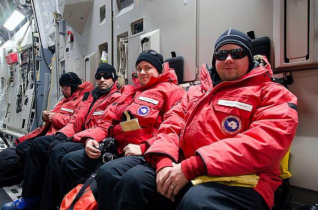
Operation IceBridge team members board a U.S. Air Force C-17 transport aircraft for a flight from Christchurch, New Zealand, to the U.S. Antarctic Program's McMurdo Station in Antarctica on Nov. 12, 2013. The C-17s that ferry people, equipment and supplies to Antarctica are operated by the U.S. Air Force's 62nd and 446th Airlift Wings based at Joint Base Lewis-McChord near Seattle, Wash. NASA's Operation IceBridge is an airborne science mission to study Earth's polar ice. In 2013, IceBridge is conducting its first field campaign directly from Antarctica. For more information about IceBridge, visit: <a href="http://www.nasa.gov/icebridge" rel="nofollow">www.nasa.gov/icebridge</a> Credit: NASA/Goddard/Jefferson Beck <b><a href="http://www.nasa.gov/audience/formedia/features/MP_Photo_Guidelines.html" rel="nofollow">NASA image use policy.</a></b> <b><a href="http://www.nasa.gov/centers/goddard/home/index.html" rel="nofollow">NASA Goddard Space Flight Center</a></b> enables NASA’s mission through four scientific endeavors: Earth Science, Heliophysics, Solar System Exploration, and Astrophysics. Goddard plays a leading role in NASA’s accomplishments by contributing compelling scientific knowledge to advance the Agency’s mission. <b>Follow us on <a href="http://twitter.com/NASA_GoddardPix" rel="nofollow">Twitter</a></b> <b>Like us on <a href="http://www.facebook.com/pages/Greenbelt-MD/NASA-Goddard/395013845897?ref=tsd" rel="nofollow">Facebook</a></b> <b>Find us on <a href="http://instagram.com/nasagoddard?vm=grid" rel="nofollow">Instagram</a></b>
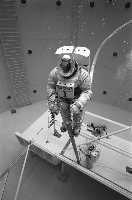
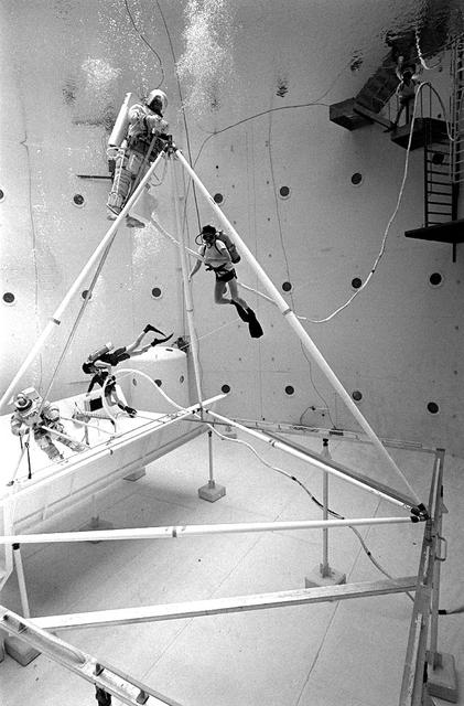
Once the United States' space program had progressed from Earth's orbit into outerspace, the prospect of building and maintaining a permanent presence in space was realized. To accomplish this feat, NASA launched a temporary workstation, Skylab, to discover the effects of low gravity and weightlessness on the human body, and also to develop tools and equipment that would be needed in the future to build and maintain a more permanent space station. The structures, techniques, and work schedules had to be carefully designed to fit this unique construction site. The components had to be lightweight for transport into orbit, yet durable. The station also had to be made with removable parts for easy servicing and repairs by astronauts. All of the tools necessary for service and repairs had to be designed for easy manipulation by a suited astronaut. Construction methods had to be efficient due to the limited time the astronauts could remain outside their controlled environment. In lieu of all the specific needs for this project, an environment on Earth had to be developed that could simulate a low gravity atmosphere. A Neutral Buoyancy Simulator (NBS) was constructed by NASA Marshall Space Flight Center (MSFC) in 1968. Since then, NASA scientists have used this facility to understand how humans work best in low gravity and also provide information about the different kinds of structures that can be built. With the help of the NBS, building a space station became more of a reality. In a joint venture between NASA/Langley Research Center in Hampton, Virginia and the MSFC, the Assembly Concept for Construction of Erectable Space Structures (ACCESS) was developed and demonstrated at MSFC's NBS. The primary objective of this experiment was to test the ACCESS structural assembly concept for suitability as the framework for larger space structures and to identify ways to improve the productivity of space construction. Pictured is a demonstration of ACCESS.
These IceBridge team members aboard a huge U.S. Air Force C-17 transport aircraft are ready to step out into the cold Antarctic air. The C-17 aircraft that fly to Antarctica are operated by the U.S. Air Force's 62nd and 446th Airlift Wings based at Joint Base Lewis-McChord near Seattle, Wash. Credit: NASA/Goddard/Michael Studinger NASA's Operation IceBridge is an airborne science mission to study Earth's polar ice. For more information about IceBridge, visit: <a href="http://www.nasa.gov/icebridge" rel="nofollow">www.nasa.gov/icebridge</a> <b><a href="http://www.nasa.gov/audience/formedia/features/MP_Photo_Guidelines.html" rel="nofollow">NASA image use policy.</a></b> <b><a href="http://www.nasa.gov/centers/goddard/home/index.html" rel="nofollow">NASA Goddard Space Flight Center</a></b> enables NASA’s mission through four scientific endeavors: Earth Science, Heliophysics, Solar System Exploration, and Astrophysics. Goddard plays a leading role in NASA’s accomplishments by contributing compelling scientific knowledge to advance the Agency’s mission. <b>Follow us on <a href="http://twitter.com/NASA_GoddardPix" rel="nofollow">Twitter</a></b> <b>Like us on <a href="http://www.facebook.com/pages/Greenbelt-MD/NASA-Goddard/395013845897?ref=tsd" rel="nofollow">Facebook</a></b> <b>Find us on <a href="http://instagram.com/nasagoddard?vm=grid" rel="nofollow">Instagram</a></b>
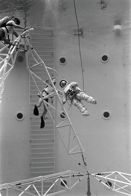
Once the United States' space program had progressed from Earth's orbit into outerspace, the prospect of building and maintaining a permanent presence in space was realized. To accomplish this feat, NASA launched a temporary workstation, Skylab, to discover the effects of low gravity and weightlessness on the human body, and also to develop tools and equipment that would be needed in the future to build and maintain a more permanent space station. The structures, techniques, and work schedules had to be carefully designed to fit this unique construction site. The components had to be lightweight for transport into orbit, yet durable. The station also had to be made with removable parts for easy servicing and repairs by astronauts. All of the tools necessary for service and repairs had to be designed for easy manipulation by a suited astronaut. And construction methods had to be efficient due to limited time the astronauts could remain outside their controlled environment. In lieu of all the specific needs for this project, an environment on Earth had to be developed that could simulate a low gravity atmosphere. A Neutral Buoyancy Simulator (NBS) was constructed by NASA Marshall Space Flight Center (MSFC) in 1968. Since then, NASA scientists have used this facility to understand how humans work best in low gravity and also provide information about the different kinds of structures that can be built. With the help of the NBS, building a space station became more of a reality. In a joint venture between NASA/Langley Research Center in Hampton, VA and MSFC, the Assembly Concept for Construction of Erectable Space Structures (ACCESS) was developed and demonstrated at MSFC's NBS. The primary objective of this experiment was to test the ACCESS structural assembly concept for suitability as the framework for larger space structures and to identify ways to improve the productivity of space construction. Pictured is a demonstration of ACCESS.
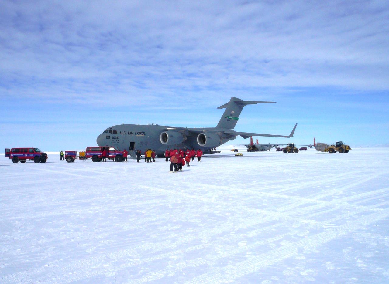
A U.S. Air Force C-17 transport aircraft sits on the sea ice runway at the National Science Foundation's McMurdo Station in Antarctica following a transit flight from Christchurch, New Zealand that transported IceBridge personnel and gear on Nov. 12, 2013. The C-17 aircraft that fly to Antarctica are operated by the U.S. Air Force's 62nd and 446th Airlift Wings based at Joint Base Lewis-McChord near Seattle, Wash. Credit: NASA/Goddard/George Hale NASA's Operation IceBridge is an airborne science mission to study Earth's polar ice. For more information about IceBridge, visit: <a href="http://www.nasa.gov/icebridge" rel="nofollow">www.nasa.gov/icebridge</a> <b><a href="http://www.nasa.gov/audience/formedia/features/MP_Photo_Guidelines.html" rel="nofollow">NASA image use policy.</a></b> <b><a href="http://www.nasa.gov/centers/goddard/home/index.html" rel="nofollow">NASA Goddard Space Flight Center</a></b> enables NASA’s mission through four scientific endeavors: Earth Science, Heliophysics, Solar System Exploration, and Astrophysics. Goddard plays a leading role in NASA’s accomplishments by contributing compelling scientific knowledge to advance the Agency’s mission. <b>Follow us on <a href="http://twitter.com/NASA_GoddardPix" rel="nofollow">Twitter</a></b> <b>Like us on <a href="http://www.facebook.com/pages/Greenbelt-MD/NASA-Goddard/395013845897?ref=tsd" rel="nofollow">Facebook</a></b> <b>Find us on <a href="http://instagram.com/nasagoddard?vm=grid" rel="nofollow">Instagram</a></b>
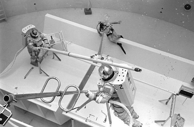
Once the United States' space program had progressed from Earth's orbit into outerspace, the prospect of building and maintaining a permanent presence in space was realized. To accomplish this feat, NASA launched a temporary workstation, Skylab, to discover the effects of low gravity and weightlessness on the human body, and also to develop tools and equipment that would be needed in the future to build and maintain a more permanent space station. The structures, techniques, and work schedules had to be carefully designed to fit this unique construction site. The components had to be lightweight for transport into orbit, yet durable. The station also had to be made with removable parts for easy servicing and repairs by astronauts. All of the tools necessary for service and repairs had to be designed for easy manipulation by a suited astronaut. And construction methods had to be efficient due to limited time the astronauts could remain outside their controlled environment. In lieu of all the specific needs for this project, an environment on Earth had to be developed that could simulate a low gravity atmosphere. A Neutral Buoyancy Simulator (NBS) was constructed by NASA Marshall Space Flight Center (MSFC) in 1968. Since then, NASA scientists have used this facility to understand how humans work best in low gravity and also provide information about the different kinds of structures that can be built. With the help of the NBS, building a space station became more of a reality. In a joint venture between NASA/Langley Research Center in Hampton, VA and MSFC, the Assembly Concept for Construction of Erectable Space Structures (ACCESS) was developed and demonstrated at MSFC's NBS. The primary objective of this experiment was to test the ACCESS structural assembly concept for suitability as the framework for larger space structures and to identify ways to improve the productivity of space construction. Pictured is a demonstration of ACCESS.
Once the United States' space program had progressed from Earth's orbit into outerspace, the prospect of building and maintaining a permanent presence in space was realized. To accomplish this feat, NASA launched a temporary workstation, Skylab, to discover the effects of low gravity and weightlessness on the human body, and also to develop tools and equipment that would be needed in the future to build and maintain a more permanent space station. The structures, techniques, and work schedules had to be carefully designed to fit this unique construction site. The components had to be lightweight for transport into orbit, yet durable. The station also had to be made with removable parts for easy servicing and repairs by astronauts. All of the tools necessary for service and repairs had to be designed for easy manipulation by a suited astronaut. And construction methods had to be efficient due to limited time the astronauts could remain outside their controlled environment. In lieu of all the specific needs for this project, an environment on Earth had to be developed that could simulate a low gravity atmosphere. A Neutral Buoyancy Simulator (NBS) was constructed by NASA Marshall Space Flight Center (MSFC) in 1968. Since then, NASA scientists have used this facility to understand how humans work best in low gravity and also provide information about the different kinds of structures that can be built. With the help of the NBS, building a space station became more of a reality. In a joint venture between NASA/Langley Research Center in Hampton, VA and MSFC, the Assembly Concept for Construction of Erectable Space Structures (ACCESS) was developed and demonstrated at MSFC's NBS. The primary objective of this experiment was to test the ACCESS structural assembly concept for suitability as the framework for larger space structures and to identify ways to improve the productivity of space construction. Pictured is a demonstration of ACCESS.
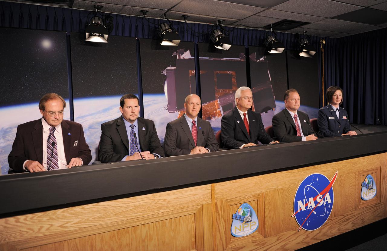
VANDENBERG AIR FORCE BASE, Calif. -- Participants in the prelaunch news conference for NASA’s National Polar-orbiting Operational Environmental Satellite System Preparatory Project (NPP) spacecraft prepare to address members of the news media gathered at Vandenberg Air Force Base, Calif. Panelists are, from left, George Diller, NASA launch commentator, Andrew Carson, NPP program executive, NASA Headquarters, Tim Dunn, NASA launch director, Kennedy Space Center, Vernon Thorp, program manager, NASA missions, United Launch Alliance, Ken Schwer, NPP project manager, Goddard Space Flight Center, and 2nd Lt. Lisa Cochran, launch weather officer, 30th Operations Support Squadron, Vandenberg Air Force Base, Calif. NPP represents a critical first step in building the next-generation of Earth-observing satellites. NPP will carry the first of the new sensors developed for this satellite fleet, now known as the Joint Polar Satellite System (JPSS), to be launched in 2016. NPP is the bridge between NASA's Earth Observing System (EOS) satellites and the forthcoming series of JPSS satellites. The mission will test key technologies and instruments for the JPSS missions. NPP is targeted to launch Oct. 28 from Space Launch Complex-2 aboard a United Launch Alliance Delta II rocket. For more information, visit http://www.nasa.gov/NPP. Photo credit: NASA/VAFB

Photo taken aboard a U.S. Air Force C-17 transport aircraft during a flight from Christchurch, New Zealand, to the U.S. Antarctic Program's McMurdo Station in Antarctica on Nov. 12, 2013. The C-17s that ferry people, equipment and supplies to Antarctica are operated by the U.S. Air Force's 62nd and 446th Airlift Wings based at Joint Base Lewis-McChord near Seattle, Wash. NASA's Operation IceBridge is an airborne science mission to study Earth's polar ice. In 2013, IceBridge is conducting its first field campaign directly from Antarctica. For more information about IceBridge, visit: <a href="http://www.nasa.gov/icebridge" rel="nofollow">www.nasa.gov/icebridge</a> Credit: NASA/Goddard/Jefferson Beck <b><a href="http://www.nasa.gov/audience/formedia/features/MP_Photo_Guidelines.html" rel="nofollow">NASA image use policy.</a></b> <b><a href="http://www.nasa.gov/centers/goddard/home/index.html" rel="nofollow">NASA Goddard Space Flight Center</a></b> enables NASA’s mission through four scientific endeavors: Earth Science, Heliophysics, Solar System Exploration, and Astrophysics. Goddard plays a leading role in NASA’s accomplishments by contributing compelling scientific knowledge to advance the Agency’s mission. <b>Follow us on <a href="http://twitter.com/NASA_GoddardPix" rel="nofollow">Twitter</a></b> <b>Like us on <a href="http://www.facebook.com/pages/Greenbelt-MD/NASA-Goddard/395013845897?ref=tsd" rel="nofollow">Facebook</a></b> <b>Find us on <a href="http://instagram.com/nasagoddard?vm=grid" rel="nofollow">Instagram</a></b>
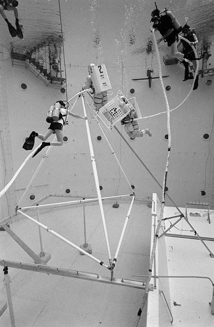
Once the United States' space program had progressed from Earth's orbit into outerspace, the prospect of building and maintaining a permanent presence in space was realized. To accomplish this feat, NASA launched a temporary workstation, Skylab, to discover the effects of low gravity and weightlessness on the human body, and also to develop tools and equipment that would be needed in the future to build and maintain a more permanent space station. The structures, techniques, and work schedules had to be carefully designed to fit this unique construction site. The components had to be lightweight for transport into orbit, yet durable. The station also had to be made with removable parts for easy servicing and repairs by astronauts. All of the tools necessary for service and repairs had to be designed for easy manipulation by a suited astronaut. And construction methods had to be efficient due to limited time the astronauts could remain outside their controlled environment. In lieu of all the specific needs for this project, an environment on Earth had to be developed that could simulate a low gravity atmosphere. A Neutral Buoyancy Simulator (NBS) was constructed by NASA Marshall Space Flight Center (MSFC) in 1968. Since then, NASA scientists have used this facility to understand how humans work best in low gravity and also provide information about the different kinds of structures that can be built. With the help of the NBS, building a space station became more of a reality. In a joint venture between NASA/Langley Research Center in Hampton, VA and MSFC, the Assembly Concept for Construction of Erectable Space Structures (ACCESS) was developed and demonstrated at MSFC's NBS. The primary objective of this experiment was to test the ACCESS structural assembly concept for suitability as the framework for larger space structures and to identify ways to improve the productivity of space construction. Pictured is a demonstration of ACCESS.

NASA Operation IceBridge pilot Michael Anderson chats with Lt. Colonel Brent Keenan aboard a U.S. Air Force C-17 transport aircraft during a flight from Christchurch, New Zealand, to the U.S. Antarctic Program's McMurdo Station in Antarctica on Nov. 12, 2013. The C-17s that ferry people, equipment and supplies to Antarctica are operated by the U.S. Air Force's 62nd and 446th Airlift Wings based at Joint Base Lewis-McChord near Seattle, Wash. NASA's Operation IceBridge is an airborne science mission to study Earth's polar ice. In 2013, IceBridge is conducting its first field campaign directly from Antarctica. For more information about IceBridge, visit: <a href="http://www.nasa.gov/icebridge" rel="nofollow">www.nasa.gov/icebridge</a> Credit: NASA/Goddard/Jefferson Beck <b><a href="http://www.nasa.gov/audience/formedia/features/MP_Photo_Guidelines.html" rel="nofollow">NASA image use policy.</a></b> <b><a href="http://www.nasa.gov/centers/goddard/home/index.html" rel="nofollow">NASA Goddard Space Flight Center</a></b> enables NASA’s mission through four scientific endeavors: Earth Science, Heliophysics, Solar System Exploration, and Astrophysics. Goddard plays a leading role in NASA’s accomplishments by contributing compelling scientific knowledge to advance the Agency’s mission. <b>Follow us on <a href="http://twitter.com/NASA_GoddardPix" rel="nofollow">Twitter</a></b> <b>Like us on <a href="http://www.facebook.com/pages/Greenbelt-MD/NASA-Goddard/395013845897?ref=tsd" rel="nofollow">Facebook</a></b> <b>Find us on <a href="http://instagram.com/nasagoddard?vm=grid" rel="nofollow">Instagram</a></b>
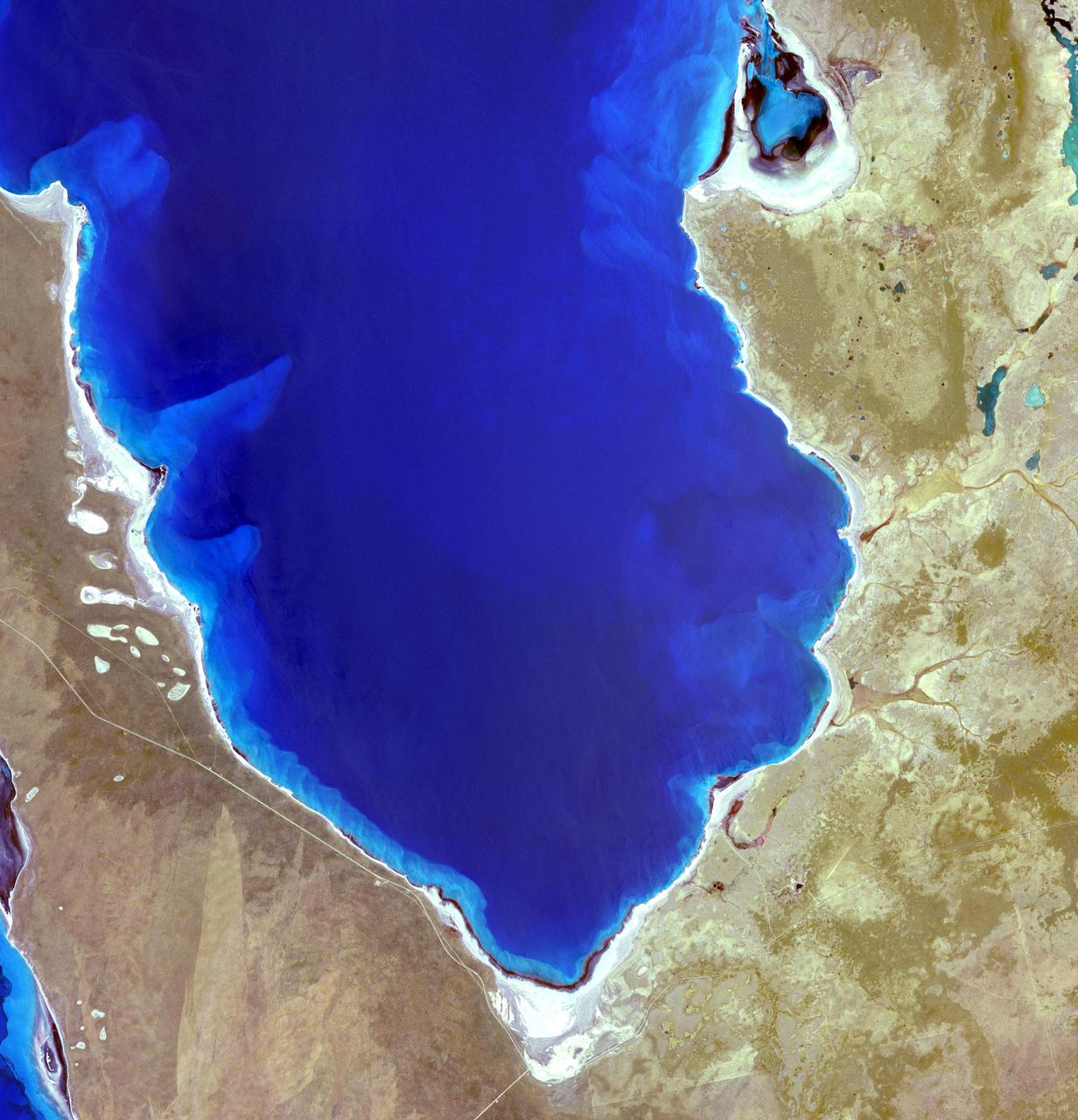
Hamelin Pool Marine Nature Reserve is located in the Shark Bay World Heritage Site in Western Australia. It is one of the very few places in the world where living stromatolites can be found. These are the first living examples of structures built by cyanobacteria. These bacteria are direct descendants of the oldest form of photosynthetic life on earth, dating back 3,500 million years (Wikipedia). The image was acquired December 30, 2010, covers an area of 34 x 46 km, and is located at 26.4 degrees south latitude, 114.1 degrees east longitude. With its 14 spectral bands from the visible to the thermal infrared wavelength region and its high spatial resolution of 15 to 90 meters (about 50 to 300 feet), ASTER images Earth to map and monitor the changing surface of our planet. ASTER is one of five Earth-observing instruments launched Dec. 18, 1999, on Terra. The instrument was built by Japan's Ministry of Economy, Trade and Industry. A joint U.S./Japan science team is responsible for validation and calibration of the instrument and data products. The broad spectral coverage and high spectral resolution of ASTER provides scientists in numerous disciplines with critical information for surface mapping and monitoring of dynamic conditions and temporal change. Example applications are: monitoring glacial advances and retreats; monitoring potentially active volcanoes; identifying crop stress; determining cloud morphology and physical properties; wetlands evaluation; thermal pollution monitoring; coral reef degradation; surface temperature mapping of soils and geology; and measuring surface heat balance. The U.S. science team is located at NASA's Jet Propulsion Laboratory, Pasadena, Calif. The Terra mission is part of NASA's Science Mission Directorate, Washington, D.C. More information about ASTER is available at <a href="http://asterweb.jpl.nasa.gov/" rel="nofollow">asterweb.jpl.nasa.gov/</a>. Credit: NASA/GSFC/METI/ERSDAC/JAROS, and U.S./Japan ASTER Science Team Image Addition Date: 2013-03-15 <b><a href="http://www.nasa.gov/audience/formedia/features/MP_Photo_Guidelines.html" rel="nofollow">NASA image use policy.</a></b> <b><a href="http://www.nasa.gov/centers/goddard/home/index.html" rel="nofollow">NASA Goddard Space Flight Center</a></b> enables NASA’s mission through four scientific endeavors: Earth Science, Heliophysics, Solar System Exploration, and Astrophysics. Goddard plays a leading role in NASA’s accomplishments by contributing compelling scientific knowledge to advance the Agency’s mission. <b>Follow us on <a href="http://twitter.com/NASA_GoddardPix" rel="nofollow">Twitter</a></b> <b>Like us on <a href="http://www.facebook.com/pages/Greenbelt-MD/NASA-Goddard/395013845897?ref=tsd" rel="nofollow">Facebook</a></b> <b>Find us on <a href="http://instagram.com/nasagoddard?vm=grid" rel="nofollow">Instagram</a></b>
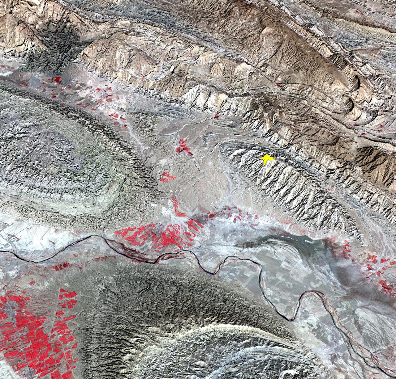
On April 9, 2013 at 11:52 GMT, a magnitude 6.3 earthquake hit southwestern Iran's Bushehr province near the town of Kaki. Preliminary information is that several villages have been destroyed and many people have died, as reported by BBC News. This perspective view of the region was acquired Nov. 17, 2012, by the Advanced Spaceborne Thermal Emission and Reflection Radiometer (ASTER) instrument on NASA's Terra spacecraft. The location of the earthquake's epicenter is marked with a yellow star. Vegetation is displayed in red; the vertical exaggeration of the topography is 2X. The image is centered near 28.5 degrees north latitude, 51.6 degrees east longitude. With its 14 spectral bands from the visible to the thermal infrared wavelength region and its high spatial resolution of 15 to 90 meters (about 50 to 300 feet), ASTER images Earth to map and monitor the changing surface of our planet. ASTER is one of five Earth-observing instruments launched Dec. 18, 1999, on Terra. The instrument was built by Japan's Ministry of Economy, Trade and Industry. A joint U.S./Japan science team is responsible for validation and calibration of the instrument and data products. The broad spectral coverage and high spectral resolution of ASTER provides scientists in numerous disciplines with critical information for surface mapping and monitoring of dynamic conditions and temporal change. Example applications are: monitoring glacial advances and retreats; monitoring potentially active volcanoes; identifying crop stress; determining cloud morphology and physical properties; wetlands evaluation; thermal pollution monitoring; coral reef degradation; surface temperature mapping of soils and geology; and measuring surface heat balance. The U.S. science team is located at NASA's Jet Propulsion Laboratory, Pasadena, Calif. The Terra mission is part of NASA's Science Mission Directorate, Washington, D.C. More information about ASTER is available at <a href="http://asterweb.jpl.nasa.gov/" rel="nofollow">asterweb.jpl.nasa.gov/</a>. Image Credit: NASA/GSFC/METI/ERSDAC/JAROS, and U.S./Japan ASTER Science Team Image Addition Date: 2013-04-10 <b><a href="http://www.nasa.gov/audience/formedia/features/MP_Photo_Guidelines.html" rel="nofollow">NASA image use policy.</a></b> <b><a href="http://www.nasa.gov/centers/goddard/home/index.html" rel="nofollow">NASA Goddard Space Flight Center</a></b> enables NASA’s mission through four scientific endeavors: Earth Science, Heliophysics, Solar System Exploration, and Astrophysics. Goddard plays a leading role in NASA’s accomplishments by contributing compelling scientific knowledge to advance the Agency’s mission. <b>Follow us on <a href="http://twitter.com/NASA_GoddardPix" rel="nofollow">Twitter</a></b> <b>Like us on <a href="http://www.facebook.com/pages/Greenbelt-MD/NASA-Goddard/395013845897?ref=tsd" rel="nofollow">Facebook</a></b> <b>Find us on <a href="http://instagram.com/nasagoddard?vm=grid" rel="nofollow">Instagram</a></b>
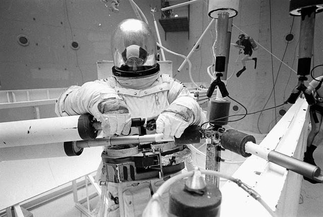
Once the United States' space program had progressed from Earth's orbit into outerspace, the prospect of building and maintaining a permanent presence in space was realized. To accomplish this feat, NASA launched a temporary workstation, Skylab, to discover the effects of low gravity and weightlessness on the human body, and also to develop tools and equipment that would be needed in the future to build and maintain a more permanent space station. The structures, techniques, and work schedules had to be carefully designed to fit this unique construction site. The components had to be lightweight for transport into orbit, yet durable. The station also had to be made with removable parts for easy servicing and repairs by astronauts. All of the tools necessary for service and repairs had to be designed for easy manipulation by a suited astronaut. Construction methods had to be efficient due to the limited time the astronauts could remain outside their controlled environment. In lieu of all the specific needs for this project, an environment on Earth had to be developed that could simulate a low gravity atmosphere. A Neutral Buoyancy Simulator (NBS) was constructed by NASA's Marshall Space Flight Center (MSFC) in 1968. Since then, NASA scientists have used this facility to understand how humans work best in low gravity and also provide information about the different kinds of structures that can be built. Pictured is a Massachusetts Institute of Technology (MIT) student working in a spacesuit on the Experimental Assembly of Structures in Extravehicular Activity (EASE) project which was developed as a joint effort between MFSC and MIT. The EASE experiment required that crew members assemble small components to form larger components, working from the payload bay of the space shuttle. The MIT student in this photo is assembling two six-beam tetrahedrons.
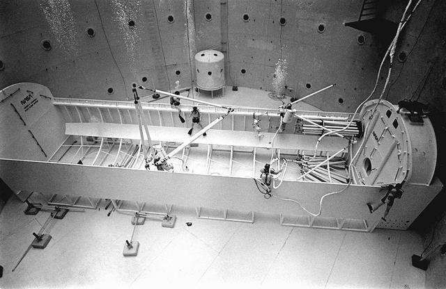
Once the United States' space program had progressed from Earth's orbit into outerspace, the prospect of building and maintaining a permanent presence in space was realized. To accomplish this feat, NASA launched a temporary workstation, Skylab, to discover the effects of low gravity and weightlessness on the human body, and also to develop tools and equipment that would be needed in the future to build and maintain a more permanent space station. The structures, techniques, and work schedules had to be carefully designed to fit this unique construction site. The components had to be lightweight for transport into orbit, yet durable. The station also had to be made with removable parts for easy servicing and repairs by astronauts. All of the tools necessary for service and repairs had to be designed for easy manipulation by a suited astronaut. Construction methods had to be efficient due to the limited time the astronauts could remain outside their controlled environment. In lieu of all the specific needs for this project, an environment on Earth had to be developed that could simulate a low gravity atmosphere. A Neutral Buoyancy Simulator (NBS) was constructed by NASA Marshall Space Flight Center (MSFC) in 1968. Since then, NASA scientists have used this facility to understand how humans work best in low gravity and also provide information about the different kinds of structures that can be built. As part of this experimentation, the Experimental Assembly of Structures in Extravehicular Activity (EASE) project was developed as a joint effort between MFSC and the Massachusetts Institute of Technology (MIT). The EASE experiment required that crew members assemble small components to form larger components, working from the payload bay of the space shuttle. Pictured is an entire unit that has been constructed and is sitting in the bottom of a mock-up shuttle cargo bay pallet.
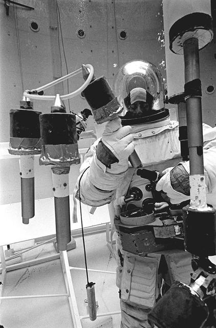
Once the United States' space program had progressed from Earth's orbit into outerspace, theprospect of building and maintaining a permanent presence in space was realized. To accomplish this feat, NASA launched a temporary workstation, Skylab, to discover the effects of low gravity and weightlessness on the human body, and also to develop tools and equipment that would be needed in the future to build and maintain a more permanent space station. The structures, techniques, and work schedules had to be carefully designed to fit this unique construction site. The components had to be lightweight for transport into orbit, yet durable. The station also had to be made with removable parts for easy servicing and repairs by astronauts. All of the tools necessary for service and repairs had to be designed for easy manipulation by a suited astronaut. Construction methods had to be efficient due to the limited time the astronauts could remain outside their controlled environment. In lieu of all the specific needs for this project, an environment on Earth had to be developed that could simulate a low gravity atmosphere. A Neutral Buoyancy Simulator (NBS) was constructed by NASA's Marshall Space Flight Center (MSFC) in 1968. Since then, NASA scientists have used this facility to understand how humans work best in low gravity and also provide information about the different kinds of structures that can be built. Pictured is a Massachusetts Institute of Technology (MIT) student working in a spacesuit on the Experimental Assembly of Structures in Extravehicular Activity (EASE) project which was developed as a joint effort between MFSC and MIT. The EASE experiment required that crew members assemble small components to form larger components, working from the payload bay of the space shuttle. The MIT student in this photo is assembling two six-beam tetrahedrons.
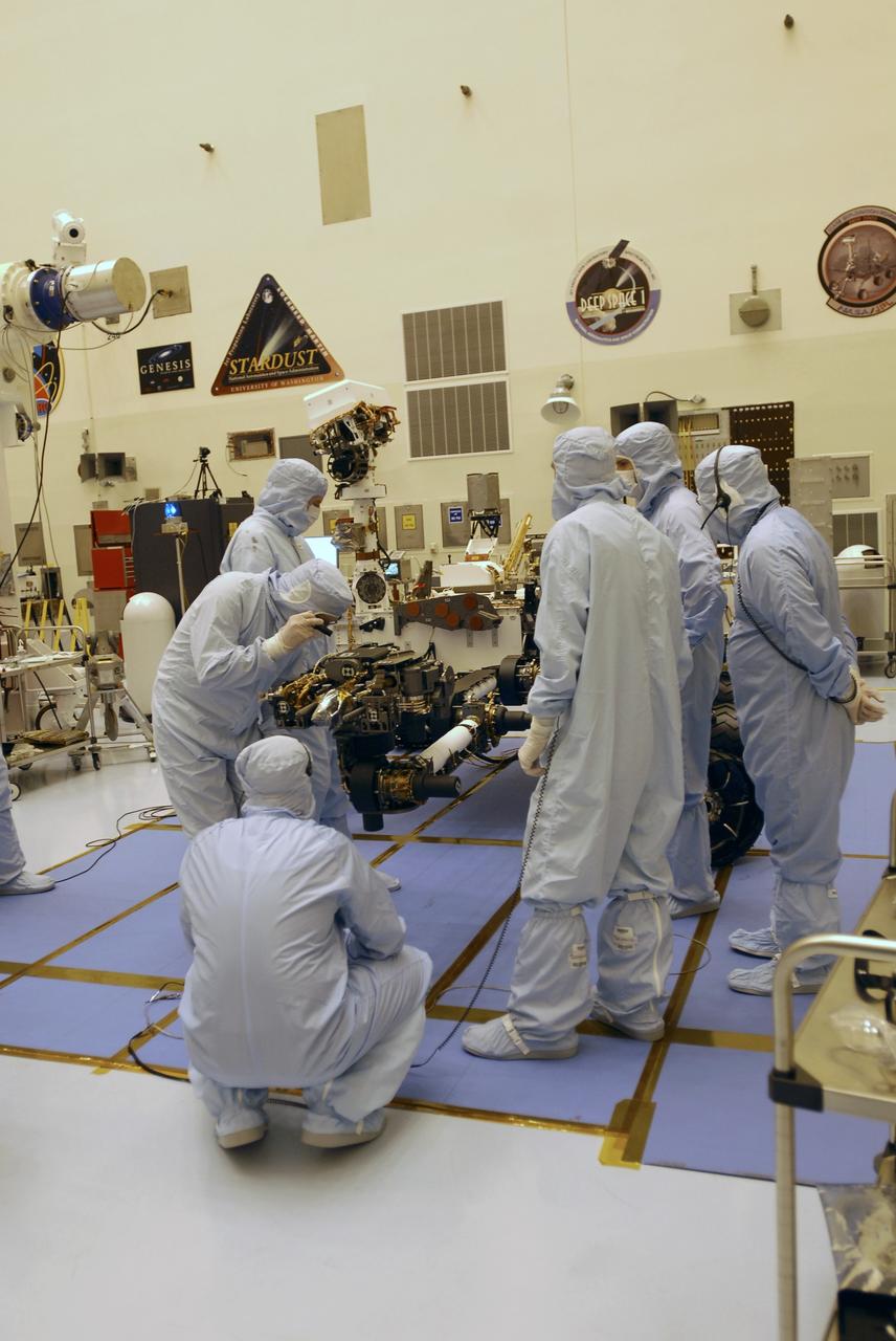
CAPE CANAVERAL, Fla. -- In the Payload Hazardous Servicing Facility at NASA's Kennedy Space Center in Florida, spacecraft technicians examine the Mars Science Laboratory (MSL) rover, Curiosity, to ensure that the proper steps have been taken to stow the spacecraft's robotic arm. The arm will hold and maneuver instruments that will help scientists analyze Martian rocks and soil. Much like a human arm, the robotic arm has flexibility through shoulder, elbow, and wrist joints that permit the arm to extend, bend, and angle precisely against rocks and soil to grind away layers, take microscopic images and analyze their elemental composition. At the end of the arm is a hand-like structure, the turret, for holding various tools that can spin through a 350-degree turning range. A United Launch Alliance Atlas V-541 configuration will be used to loft MSL into space. Curiosity’s 10 science instruments are designed to search for evidence on whether Mars has had environments favorable to microbial life, including chemical ingredients for life. The unique rover will use a laser to look inside rocks and release its gasses so that the rover’s spectrometer can analyze and send the data back to Earth. MSL is scheduled to launch Nov. 25 from Space Launch Complex 41 on Cape Canaveral Air Force Station in Florida. For more information, visit http://www.nasa.gov/msl. Photo credit: NASA/Charisse Nahser
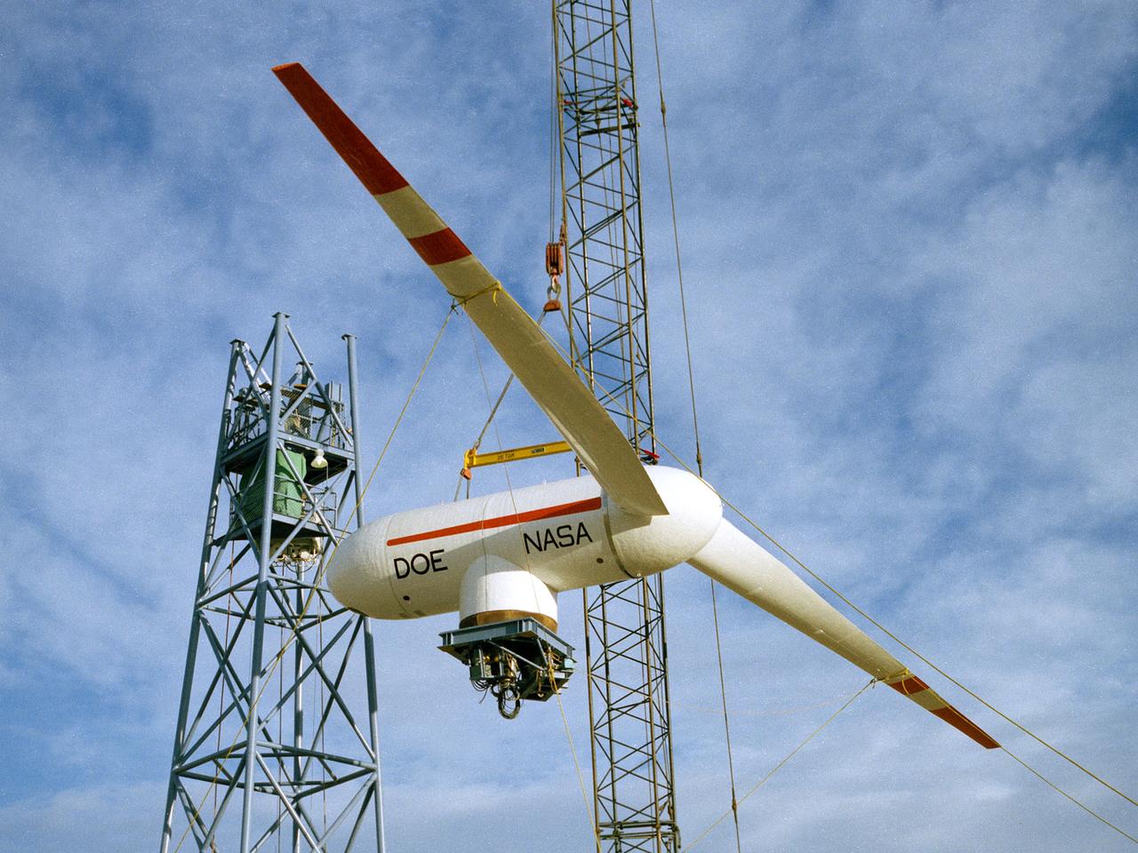
TA Mod-0A 200-kilowatt wind turbine designed by National Aeronautics and Space Administration (NASA) Lewis Research Center and constructed in Clayton, New Mexico. The wind turbine program was a joint effort by NASA and the Energy Research and Development Administration (ERDA) during the 1970s to develop less expensive forms of energy. NASA Lewis was assigned the responsibility of developing large horizontal-axis wind turbines. The program included a series of increasingly powerful wind turbines, designated: Mod-0A, Mod-1, WTS-4, and Mod-5. The program’s first device was a Mod-0 100-kilowatt wind turbine test bed built at NASA’s Plum Brook Station. This Mod-0A 200-kilowatt turbine built in Clayton in 1977 was the program’s second device. It included a 125-foot long blade atop a 100-foot tall tower. The Mod-0A was designed to determine the turbine’s operating problems, integrate the system with the local utilities, and assess the attitude of the local community. There were additional Mod-0A turbines built in Culebra, Puerto Rico; Block Island, Rhode Island; and Oahu, Hawaii. The Mod-0A turbines were initially unreliable and suffered issues with the durability of the rotor blade. Lewis engineers addressed the problems, and the wind turbines proved to be reliable and efficient devices that operated for a number of years. The information gained from these early models was vital to the design and improvement of the later generations.
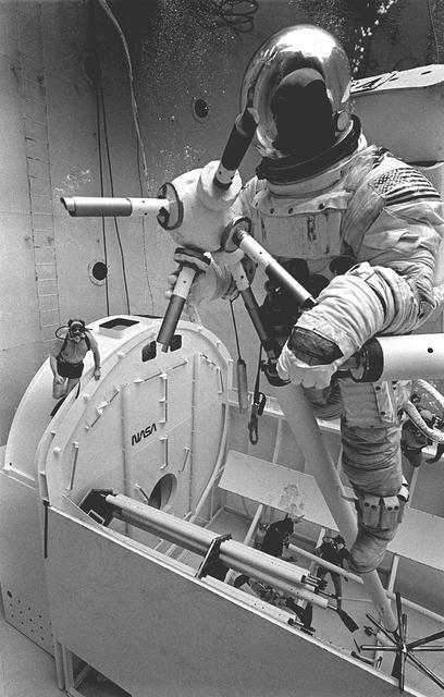
Once the United States' space program had progressed from Earth's orbit into outerspace, the prospect of building and maintaining a permanent presence in space was realized. To accomplish this feat, NASA launched a temporary workstation, Skylab, to discover the effects of low gravity and weightlessness on the human body, and also to develop tools and equipment that would be needed in the future to build and maintain a more permanent space station. The structures, techniques, and work schedules had to be carefully designed to fit this unique construction site. The components had to be lightweight for transport into orbit, yet durable. The station also had to be made with removable parts for easy servicing and repairs by astronauts. All of the tools necessary for service and repairs had to be designed for easy manipulation by a suited astronaut. Construction methods had to be efficient due to the limited time the astronauts could remain outside their controlled environment. In lieu of all the specific needs for this project, an environment on Earth had to be developed that could simulate a low gravity atmosphere. A Neutral Buoyancy Simulator (NBS) was constructed by NASA's Marshall Space Flight Center (MSFC) in 1968. Since then, NASA scientists have used this facility to understand how humans work best in low gravity and also provide information about the different kinds of structures that can be built. Pictured is a Massachusetts Institute of Technology (MIT) student working in a spacesuit on the Experimental Assembly of Structures in Extravehicular Activity (EASE) project which was developed as a joint effort between MFSC and MIT. The EASE experiment required that crew members assemble small components to form larger components, working from the payload bay of the space shuttle. The MIT student in this photo is assembling two six-beam tetrahedrons.
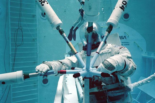
Once the United States' space program had progressed from Earth's orbit into outerspace, the prospect of building and maintaining a permanent presence in space was realized. To accomplish this feat, NASA launched a temporary workstation, Skylab, to discover the effects of low gravity and weightlessness on the human body, and also to develop tools and equipment that would be needed in the future to build and maintain a more permanent space station. The structures, techniques, and work schedules had to be carefully designed to fit this unique construction site. The components had to be lightweight for transport into orbit, yet durable. The station also had to be made with removable parts for easy servicing and repairs by astronauts. All of the tools necessary for service and repairs had to be designed for easy manipulation by a suited astronaut. And construction methods had to be efficient due to limited time the astronauts could remain outside their controlled environment. In lieu of all the specific needs for this project, an environment on Earth had to be developed that could simulate a low gravity atmosphere. A Neutral Buoyancy Simulator (NBS) was constructed by NASA Marshall Space Flight Center (MSFC) in 1968. Since then, NASA scientists have used this facility to understand how humans work best in low gravity and also provide information about the different kinds of structures that can be built. Pictured is a Massachusetts Institute of Technology (MIT) student working in a spacesuit on the Experimental Assembly of Structures in Extravehicular Activity (EASE) project which was developed as a joint effort between MFSC and MIT. The EASE experiment required that crew members assemble small components to form larger components, working from the payload bay of the space shuttle.
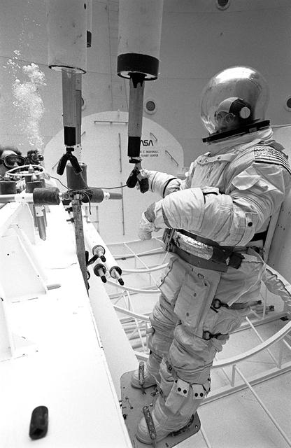
Once the United States' space program had progressed from Earth's orbit into outerspace, the prospect of building and maintaining a permanent presence in space was realized. To accomplish this feat, NASA launched a temporary workstation, Skylab, to discover the effects of low gravity and weightlessness on the human body, and also to develop tools and equipment that would be needed in the future to build and maintain a more permanent space station. The structures, techniques, and work schedules had to be carefully designed to fit this unique construction site. The components had to be lightweight for transport into orbit, yet durable. The station also had to be made with removable parts for easy servicing and repairs by astronauts. All of the tools necessary for service and repairs had to be designed for easy manipulation by a suited astronaut. Construction methods had to be efficient due to the limited time the astronauts could remain outside their controlled environment. In lieu of all the specific needs for this project, an environment on Earth had to be developed that could simulate a low gravity atmosphere. A Neutral Buoyancy Simulator (NBS) was constructed by NASA's Marshall Space Flight Center (MSFC) in 1968. Since then, NASA scientists have used this facility to understand how humans work best in low gravity and also provide information about the different kinds of structures that can be built. Pictured is a Massachusetts Institute of Technology (MIT) student working in a spacesuit on the Experimental Assembly of Structures in Extravehicular Activity (EASE) project which was developed as a joint effort between MFSC and MIT. The EASE experiment required that crew members assemble small components to form larger components, working from the payload bay of the space shuttle. The MIT student in this photo is assembling two six-beam tetrahedrons.
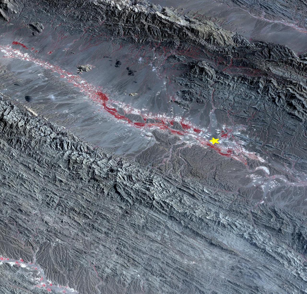
On September 24 at 11:29 GMT, a magnitude 7.7 earthquake struck in south-central Pakistan at a relatively shallow depth of 20 kilometers. The earthquake occurred as the result of oblique strike-slip motion, consistent with rupture within the Eurasian tectonic plate. Tremors were felt as far away as New Delhi as well as Karachi in Pakistan. Even though the immediate area to the epicenter is sparsely populated, the majority of houses are of mud brick construction and damage is expected to be extensive. The perspective view, looking to the east, shows the location of the epicenter in Pakistan's Makran fold belt. The image is centered near 27 degrees north latitude, 65.5 degrees east longitude, and was acquired December 13, 2012. With its 14 spectral bands from the visible to the thermal infrared wavelength region and its high spatial resolution of 15 to 90 meters (about 50 to 300 feet), ASTER images Earth to map and monitor the changing surface of our planet. ASTER is one of five Earth-observing instruments launched Dec. 18, 1999, on Terra. The instrument was built by Japan's Ministry of Economy, Trade and Industry. A joint U.S./Japan science team is responsible for validation and calibration of the instrument and data products. The broad spectral coverage and high spectral resolution of ASTER provides scientists in numerous disciplines with critical information for surface mapping and monitoring of dynamic conditions and temporal change. Example applications are: monitoring glacial advances and retreats; monitoring potentially active volcanoes; identifying crop stress; determining cloud morphology and physical properties; wetlands evaluation; thermal pollution monitoring; coral reef degradation; surface temperature mapping of soils and geology; and measuring surface heat balance. The U.S. science team is located at NASA's Jet Propulsion Laboratory, Pasadena, Calif. The Terra mission is part of NASA's Science Mission Directorate, Washington, D.C. More information about ASTER is available at <a href="http://asterweb.jpl.nasa.gov/" rel="nofollow">asterweb.jpl.nasa.gov/</a>. Image Credit: NASA/GSFC/METI/ERSDAC/JAROS, and U.S./Japan ASTER Science Team Image Addition Date: 2013-09-24 <b><a href="http://www.nasa.gov/audience/formedia/features/MP_Photo_Guidelines.html" rel="nofollow">NASA image use policy.</a></b> <b><a href="http://www.nasa.gov/centers/goddard/home/index.html" rel="nofollow">NASA Goddard Space Flight Center</a></b> enables NASA’s mission through four scientific endeavors: Earth Science, Heliophysics, Solar System Exploration, and Astrophysics. Goddard plays a leading role in NASA’s accomplishments by contributing compelling scientific knowledge to advance the Agency’s mission. <b>Follow us on <a href="http://twitter.com/NASA_GoddardPix" rel="nofollow">Twitter</a></b> <b>Like us on <a href="http://www.facebook.com/pages/Greenbelt-MD/NASA-Goddard/395013845897?ref=tsd" rel="nofollow">Facebook</a></b> <b>Find us on <a href="http://instagram.com/nasagoddard?vm=grid" rel="nofollow">Instagram</a></b>
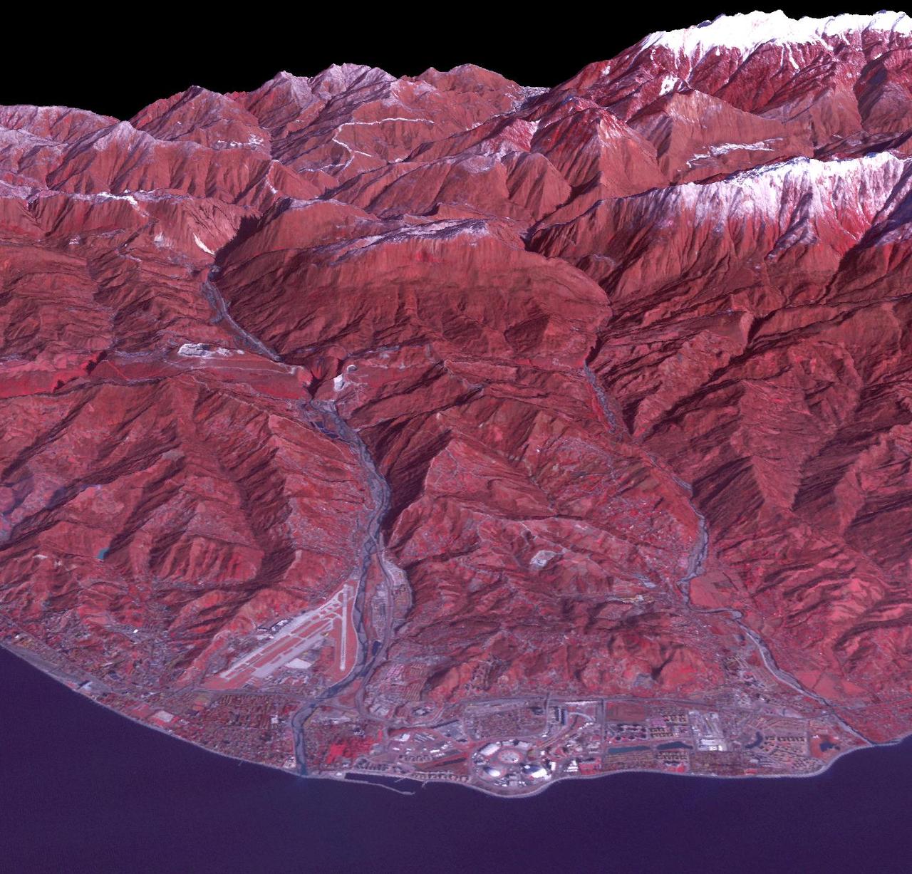
Sochi, Russia Winter Olympic Sites (Coastal Cluster) The Black Sea resort of Sochi, Russia, is the warmest city ever to host the Winter Olympic Games, which open on Feb. 7, 2014, and run through Feb. 23. This north-looking image, acquired on Jan. 4, 2014, by the Advanced Spaceborne Thermal Emission and Reflection Radiometer (ASTER) instrument on NASA's Terra spacecraft, shows the Sochi Olympic Park Coastal Cluster -- the circular area on the shoreline in the bottom center of the image -- which was built for Olympic indoor sports. Even curling has its own arena alongside multiple arenas for hockey and skating. The Olympic alpine events will take place at the Mountain Cluster, located in a snow-capped valley at the top right of the image. Sochi itself, a city of about 400,000, is not visible in the picture. It's farther west (left) along the coast, past the airport at bottom left. In the image, red indicates vegetation, white is snow, buildings are gray and the ocean is dark blue. The area imaged is about 15 miles (24 kilometers) from west to east (left to right) at the coastline and 25 miles (41 kilometers) from front to back. Height is exaggerated 1.5 times. The image was created from the ASTER visible and near-infrared bands, draped over ASTER-derived digital elevation data. With its 14 spectral bands from the visible to the thermal infrared wavelength region and its high spatial resolution of 15 to 90 meters (about 50 to 300 feet), ASTER images Earth to map and monitor the changing surface of our planet. ASTER is one of five Earth-observing instruments launched Dec. 18, 1999, on Terra. The instrument was built by Japan's Ministry of Economy, Trade and Industry. A joint U.S./Japan science team is responsible for validation and calibration of the instrument and data products. The broad spectral coverage and high spectral resolution of ASTER provides scientists in numerous disciplines with critical information for surface mapping and monitoring of dynamic conditions and temporal change. Example applications are: monitoring glacial advances and retreats; monitoring potentially active volcanoes; identifying crop stress; determining cloud morphology and physical properties; wetlands evaluation; thermal pollution monitoring; coral reef degradation; surface temperature mapping of soils and geology; and measuring surface heat balance. The U.S. science team is located at NASA's Jet Propulsion Laboratory, Pasadena, Calif. The Terra mission is part of NASA's Science Mission Directorate, Washington, D.C. More information about ASTER is available at <a href="http://asterweb.jpl.nasa.gov/" rel="nofollow">asterweb.jpl.nasa.gov/</a>. Image credit: NASA/GSFC/METI/ERSDAC/JAROS, and U.S./Japan ASTER Science Team <b><a href="http://www.nasa.gov/audience/formedia/features/MP_Photo_Guidelines.html" rel="nofollow">NASA image use policy.</a></b> <b><a href="http://www.nasa.gov/centers/goddard/home/index.html" rel="nofollow">NASA Goddard Space Flight Center</a></b> enables NASA’s mission through four scientific endeavors: Earth Science, Heliophysics, Solar System Exploration, and Astrophysics. Goddard plays a leading role in NASA’s accomplishments by contributing compelling scientific knowledge to advance the Agency’s mission. <b>Follow us on <a href="http://twitter.com/NASAGoddardPix" rel="nofollow">Twitter</a></b> <b>Like us on <a href="http://www.facebook.com/pages/Greenbelt-MD/NASA-Goddard/395013845897?ref=tsd" rel="nofollow">Facebook</a></b> <b>Find us on <a href="http://instagram.com/nasagoddard?vm=grid" rel="nofollow">Instagram</a></b>
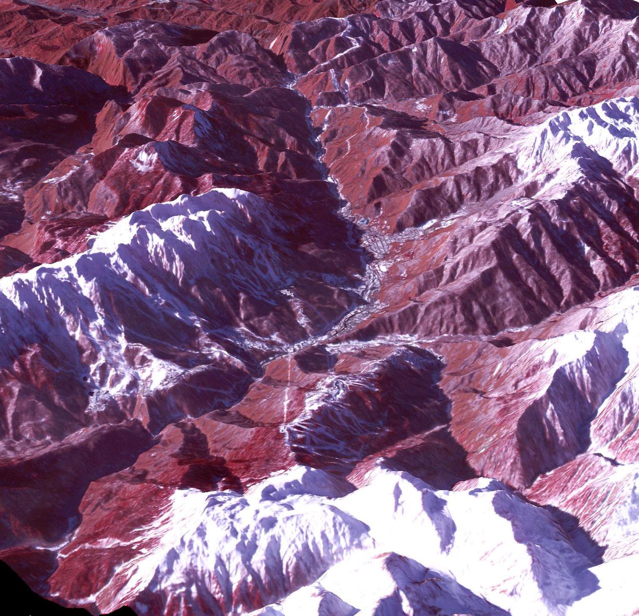
Sochi, Russia Winter Olympic Sites (Mountain Cluster) The 2014 Winter Olympic ski runs may be rated double black diamond, but they're not quite as steep as they appear in this image of the skiing and snowboarding sites for the Sochi Winter Olympic Games, acquired on Jan. 4, 2014, by the Advanced Spaceborne Thermal Emission and Reflection Radiometer (ASTER) instrument on NASA's Terra spacecraft. Rosa Khutar ski resort near Sochi, Russia, is in the valley at center, and the runs are visible on the shadowed slopes on the left-hand side of the valley. Height has been exaggerated 1.5 times to bring out topographic details. The games, which begin on Feb. 7 and continue for 17 days, feature six new skiing and boarding events plus the return of the legendary Jamaican bobsled team to the winter games for the first time since 2002. In this southwest-looking image, red indicates vegetation, white is snow, and the resort site appears in gray. The area imaged is about 11 miles (18 kilometers) across in the foreground and 20 miles (32 kilometers) from front to back. The image was created from the ASTER visible and near-infrared bands, draped over ASTER-derived digital elevation data. With its 14 spectral bands from the visible to the thermal infrared wavelength region and its high spatial resolution of 15 to 90 meters (about 50 to 300 feet), ASTER images Earth to map and monitor the changing surface of our planet. ASTER is one of five Earth-observing instruments launched Dec. 18, 1999, on Terra. The instrument was built by Japan's Ministry of Economy, Trade and Industry. A joint U.S./Japan science team is responsible for validation and calibration of the instrument and data products. The broad spectral coverage and high spectral resolution of ASTER provides scientists in numerous disciplines with critical information for surface mapping and monitoring of dynamic conditions and temporal change. Example applications are: monitoring glacial advances and retreats; monitoring potentially active volcanoes; identifying crop stress; determining cloud morphology and physical properties; wetlands evaluation; thermal pollution monitoring; coral reef degradation; surface temperature mapping of soils and geology; and measuring surface heat balance. The U.S. science team is located at NASA's Jet Propulsion Laboratory, Pasadena, Calif. The Terra mission is part of NASA's Science Mission Directorate, Washington, D.C. More information about ASTER is available at <a href="http://asterweb.jpl.nasa.gov/" rel="nofollow">asterweb.jpl.nasa.gov/</a>. credit:NASA/GSFC/METI/ERSDAC/JAROS, and U.S./Japan ASTER Science Team <b><a href="http://www.nasa.gov/audience/formedia/features/MP_Photo_Guidelines.html" rel="nofollow">NASA image use policy.</a></b> <b><a href="http://www.nasa.gov/centers/goddard/home/index.html" rel="nofollow">NASA Goddard Space Flight Center</a></b> enables NASA’s mission through four scientific endeavors: Earth Science, Heliophysics, Solar System Exploration, and Astrophysics. Goddard plays a leading role in NASA’s accomplishments by contributing compelling scientific knowledge to advance the Agency’s mission. <b>Follow us on <a href="http://twitter.com/NASAGoddardPix" rel="nofollow">Twitter</a></b> <b>Like us on <a href="http://www.facebook.com/pages/Greenbelt-MD/NASA-Goddard/395013845897?ref=tsd" rel="nofollow">Facebook</a></b> <b>Find us on <a href="http://instagram.com/nasagoddard?vm=grid" rel="nofollow">Instagram</a></b>

The powerful primary mirrors of the James Webb Space Telescope will be able to detect the light from distant galaxies. The manufacturer of those mirrors, Ball Aerospace & Technologies Corp. of Boulder, Colo., recently celebrated their successful efforts as mirror segments were packed up in special shipping canisters (cans) for shipping to NASA. The Webb telescope has 21 mirrors, with 18 primary mirror segments working together as one large 21.3-foot (6.5-meter) primary mirror. The mirror segments are made of beryllium, which was selected for its stiffness, light weight and stability at cryogenic temperatures. Bare beryllium is not very reflective of near-infrared light, so each mirror is coated with about 0.12 ounce of gold. Northrop Grumman Corp. Aerospace Systems is the principal contractor on the telescope and commissioned Ball for the optics system's development, design, manufacturing, integration and testing. The Webb telescope is the world's next-generation space observatory and successor to the Hubble Space Telescope. The most powerful space telescope ever built, the Webb telescope will provide images of the first galaxies ever formed, and explore planets around distant stars. It is a joint project of NASA, the European Space Agency and the Canadian Space Agency. For more information about the James Webb Space Telescope, visit: <a href="http://www.jwst.nasa.gov" rel="nofollow">www.jwst.nasa.gov</a> Credit: Ball Aerospace <b><a href="http://www.nasa.gov/audience/formedia/features/MP_Photo_Guidelines.html" rel="nofollow">NASA image use policy.</a></b> <b><a href="http://www.nasa.gov/centers/goddard/home/index.html" rel="nofollow">NASA Goddard Space Flight Center</a></b> enables NASA’s mission through four scientific endeavors: Earth Science, Heliophysics, Solar System Exploration, and Astrophysics. Goddard plays a leading role in NASA’s accomplishments by contributing compelling scientific knowledge to advance the Agency’s mission. <b>Follow us on <a href="http://twitter.com/NASA_GoddardPix" rel="nofollow">Twitter</a></b> <b>Like us on <a href="http://www.facebook.com/pages/Greenbelt-MD/NASA-Goddard/395013845897?ref=tsd" rel="nofollow">Facebook</a></b> <b>Find us on <a href="http://instagrid.me/nasagoddard/?vm=grid" rel="nofollow">Instagram</a></b>
Arizona produces 60% of the total copper mined in the US; in 2007, 750,000 tons of copper came out of the state. One of the major mining districts is located about 30 km south of Tucson. Starting around 1950, open-pit mining replaced underground operations, and the ASARCO-Mission complex, Twin Buttes, and Sierrita mines became large open pit operations. Accompanying copper mineralization, silver, molybdenum, zinc, lead and gold are extracted. In addition to the pits themselves, enormous leach ponds and tailings piles surround the pits. The image was acquired May 31, 2012, covers an area of 22 by 28 km, and is located at 31.9 degrees north, 111 degrees west. With its 14 spectral bands from the visible to the thermal infrared wavelength region and its high spatial resolution of 15 to 90 meters (about 50 to 300 feet), ASTER images Earth to map and monitor the changing surface of our planet. ASTER is one of five Earth-observing instruments launched Dec. 18, 1999, on Terra. The instrument was built by Japan's Ministry of Economy, Trade and Industry. A joint U.S./Japan science team is responsible for validation and calibration of the instrument and data products. The broad spectral coverage and high spectral resolution of ASTER provides scientists in numerous disciplines with critical information for surface mapping and monitoring of dynamic conditions and temporal change. Example applications are: monitoring glacial advances and retreats; monitoring potentially active volcanoes; identifying crop stress; determining cloud morphology and physical properties; wetlands evaluation; thermal pollution monitoring; coral reef degradation; surface temperature mapping of soils and geology; and measuring surface heat balance. The U.S. science team is located at NASA's Jet Propulsion Laboratory, Pasadena, Calif. The Terra mission is part of NASA's Science Mission Directorate, Washington, D.C. More information about ASTER is available at <a href="http://asterweb.jpl.nasa.gov/" rel="nofollow">asterweb.jpl.nasa.gov/</a> Credit: NASA/GSFC/METI/ERSDAC/JAROS, and U.S./Japan ASTER Science Team <b><a href="http://www.nasa.gov/audience/formedia/features/MP_Photo_Guidelines.html" rel="nofollow">NASA image use policy.</a></b> <b><a href="http://www.nasa.gov/centers/goddard/home/index.html" rel="nofollow">NASA Goddard Space Flight Center</a></b> enables NASA’s mission through four scientific endeavors: Earth Science, Heliophysics, Solar System Exploration, and Astrophysics. Goddard plays a leading role in NASA’s accomplishments by contributing compelling scientific knowledge to advance the Agency’s mission. <b>Follow us on <a href="http://twitter.com/NASAGoddardPix" rel="nofollow">Twitter</a></b> <b>Like us on <a href="http://www.facebook.com/pages/Greenbelt-MD/NASA-Goddard/395013845897?ref=tsd" rel="nofollow">Facebook</a></b> <b>Find us on <a href="http://instagram.com/nasagoddard?vm=grid" rel="nofollow">Instagram</a></b>
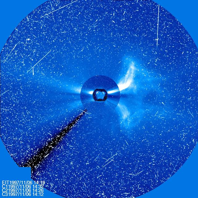
Four different instruments on SOHO show a large CME on Nov. 6, 1997. The sun is at the center, with three coronagraph images of different sizes around it. The streaks of white light are from protons hitting the SOHO cameras producing a snowy effect typical of a significant flare. ..Credit: NASA/SOHO..---..CME WEEK: What To See in CME Images Two main types of explosions occur on the sun: solar flares and coronal mass ejections. Unlike the energy and x-rays produced in a solar flare – which can reach Earth at the speed of light in eight minutes – coronal mass ejections are giant, expanding clouds of solar material that take one to three days to reach Earth. Once at Earth, these ejections, also called CMEs, can impact satellites in space or interfere with radio communications. During CME WEEK from Sept. 22 to 26, 2014, we explore different aspects of these giant eruptions that surge out from the star we live with. When a coronal mass ejection blasts off the sun, scientists rely on instruments called coronagraphs to track their progress. Coronagraphs block out the bright light of the sun, so that the much fainter material in the solar atmosphere -- including CMEs -- can be seen in the surrounding space. CMEs appear in these images as expanding shells of material from the sun's atmosphere -- sometimes a core of colder, solar material (called a filament) from near the sun's surface moves in the center. But mapping out such three-dimensional components from a two-dimensional image isn't easy. Watch the slideshow to find out how scientists interpret what they see in CME pictures. The images in the slideshow are from the three sets of coronagraphs NASA currently has in space. One is on the joint European Space Agency and NASA Solar and Heliospheric Observatory, or SOHO. SOHO launched in 1995, and sits between Earth and the sun about a million miles away from Earth. The other two coronagraphs are on the two spacecraft of the NASA Solar Terrestrial Relations Observatory, or STEREO, mission, which launched in 2006. The two STEREO spacecraft are both currently viewing the far side of the sun. Together these instruments help scientists create a three-dimensional model of any CME as its journey unfolds through interplanetary space. Such information can show why a given characteristic of a CME close to the sun might lead to a given effect near Earth, or any other planet in the solar system...<b><a href="http://www.nasa.gov/audience/formedia/features/MP_Photo_Guidelines.html" rel="nofollow">NASA image use policy.</a></b> <b><a href="http://www.nasa.gov/centers/goddard/home/index.html" rel="nofollow">NASA Goddard Space Flight Center</a></b> enables NASA’s mission through four scientific endeavors: Earth Science, Heliophysics, Solar System Exploration, and Astrophysics. Goddard plays a leading role in NASA’s accomplishments by contributing compelling scientific knowledge to advance the Agency’s mission. <b>Follow us on <a href="http://twitter.com/NASAGoddardPix" rel="nofollow">Twitter</a></b> <b>Like us on <a href="http://www.facebook.com/pages/Greenbelt-MD/NASA-Goddard/395013845897?ref=tsd" rel="nofollow">Facebook</a></b> <b>Find us on <a href="http://instagram.com/nasagoddard?vm=grid" rel="nofollow">Instagram</a></b>
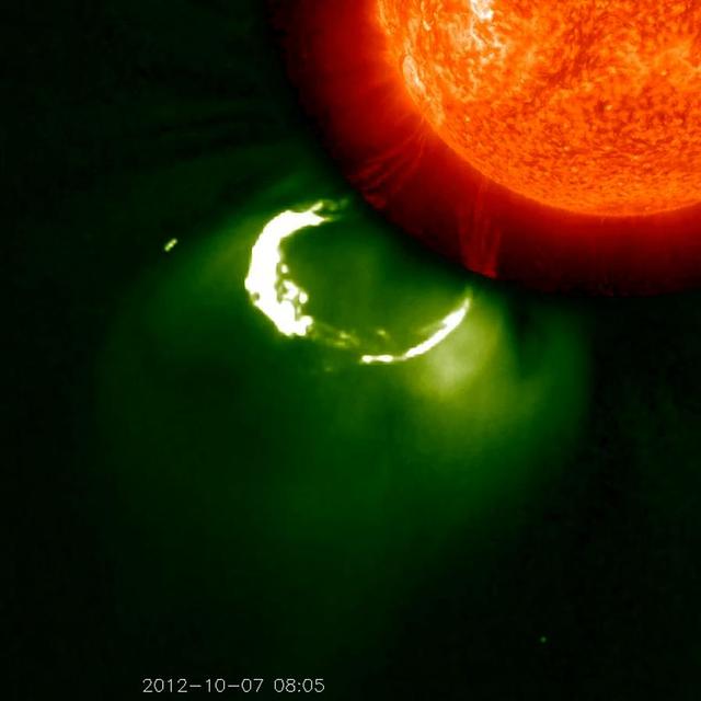
This CME image from Oct. 7, 2012, captured by two instruments on STEREO, shows the eruption from its base out into space. The base of the CME near the sun is seen in extreme ultraviolet light emitted directly from the solar material; the growing loop is seen in visible light. Credit: NASA/STEREO CME WEEK: What To See in CME Images Two main types of explosions occur on the sun: solar flares and coronal mass ejections. Unlike the energy and x-rays produced in a solar flare – which can reach Earth at the speed of light in eight minutes – coronal mass ejections are giant, expanding clouds of solar material that take one to three days to reach Earth. Once at Earth, these ejections, also called CMEs, can impact satellites in space or interfere with radio communications. During CME WEEK from Sept. 22 to 26, 2014, we explore different aspects of these giant eruptions that surge out from the star we live with. When a coronal mass ejection blasts off the sun, scientists rely on instruments called coronagraphs to track their progress. Coronagraphs block out the bright light of the sun, so that the much fainter material in the solar atmosphere -- including CMEs -- can be seen in the surrounding space. CMEs appear in these images as expanding shells of material from the sun's atmosphere -- sometimes a core of colder, solar material (called a filament) from near the sun's surface moves in the center. But mapping out such three-dimensional components from a two-dimensional image isn't easy. Watch the slideshow to find out how scientists interpret what they see in CME pictures. The images in the slideshow are from the three sets of coronagraphs NASA currently has in space. One is on the joint European Space Agency and NASA Solar and Heliospheric Observatory, or SOHO. SOHO launched in 1995, and sits between Earth and the sun about a million miles away from Earth. The other two coronagraphs are on the two spacecraft of the NASA Solar Terrestrial Relations Observatory, or STEREO, mission, which launched in 2006. The two STEREO spacecraft are both currently viewing the far side of the sun. Together these instruments help scientists create a three-dimensional model of any CME as its journey unfolds through interplanetary space. Such information can show why a given characteristic of a CME close to the sun might lead to a given effect near Earth, or any other planet in the solar system...<b><a href="http://www.nasa.gov/audience/formedia/features/MP_Photo_Guidelines.html" rel="nofollow">NASA image use policy.</a></b> <b><a href="http://www.nasa.gov/centers/goddard/home/index.html" rel="nofollow">NASA Goddard Space Flight Center</a></b> enables NASA’s mission through four scientific endeavors: Earth Science, Heliophysics, Solar System Exploration, and Astrophysics. Goddard plays a leading role in NASA’s accomplishments by contributing compelling scientific knowledge to advance the Agency’s mission. <b>Follow us on <a href="http://twitter.com/NASAGoddardPix" rel="nofollow">Twitter</a></b> <b>Like us on <a href="http://www.facebook.com/pages/Greenbelt-MD/NASA-Goddard/395013845897?ref=tsd" rel="nofollow">Facebook</a></b> <b>Find us on <a href="http://instagram.com/nasagoddard?vm=grid" rel="nofollow">Instagram</a></b>

STEREO witnessed the March 5, 2013, CME from the side of the sun – Earth is far to the left of this picture. While the SOHO images show a halo CME, STEREO shows the CME clearly moving away from Earth. Credit: NASA/STEREO --- CME WEEK: What To See in CME Images Two main types of explosions occur on the sun: solar flares and coronal mass ejections. Unlike the energy and x-rays produced in a solar flare – which can reach Earth at the speed of light in eight minutes – coronal mass ejections are giant, expanding clouds of solar material that take one to three days to reach Earth. Once at Earth, these ejections, also called CMEs, can impact satellites in space or interfere with radio communications. During CME WEEK from Sept. 22 to 26, 2014, we explore different aspects of these giant eruptions that surge out from the star we live with. When a coronal mass ejection blasts off the sun, scientists rely on instruments called coronagraphs to track their progress. Coronagraphs block out the bright light of the sun, so that the much fainter material in the solar atmosphere -- including CMEs -- can be seen in the surrounding space. CMEs appear in these images as expanding shells of material from the sun's atmosphere -- sometimes a core of colder, solar material (called a filament) from near the sun's surface moves in the center. But mapping out such three-dimensional components from a two-dimensional image isn't easy. Watch the slideshow to find out how scientists interpret what they see in CME pictures. The images in the slideshow are from the three sets of coronagraphs NASA currently has in space. One is on the joint European Space Agency and NASA Solar and Heliospheric Observatory, or SOHO. SOHO launched in 1995, and sits between Earth and the sun about a million miles away from Earth. The other two coronagraphs are on the two spacecraft of the NASA Solar Terrestrial Relations Observatory, or STEREO, mission, which launched in 2006. The two STEREO spacecraft are both currently viewing the far side of the sun. Together these instruments help scientists create a three-dimensional model of any CME as its journey unfolds through interplanetary space. Such information can show why a given characteristic of a CME close to the sun might lead to a given effect near Earth, or any other planet in the solar system. <b><a href="http://www.nasa.gov/audience/formedia/features/MP_Photo_Guidelines.html" rel="nofollow">NASA image use policy.</a></b> <b><a href="http://www.nasa.gov/centers/goddard/home/index.html" rel="nofollow">NASA Goddard Space Flight Center</a></b> enables NASA’s mission through four scientific endeavors: Earth Science, Heliophysics, Solar System Exploration, and Astrophysics. Goddard plays a leading role in NASA’s accomplishments by contributing compelling scientific knowledge to advance the Agency’s mission. <b>Follow us on <a href="http://twitter.com/NASAGoddardPix" rel="nofollow">Twitter</a></b> <b>Like us on <a href="http://www.facebook.com/pages/Greenbelt-MD/NASA-Goddard/395013845897?ref=tsd" rel="nofollow">Facebook</a></b> <b>Find us on <a href="http://instagram.com/nasagoddard?vm=grid" rel="nofollow">Instagram</a></b>
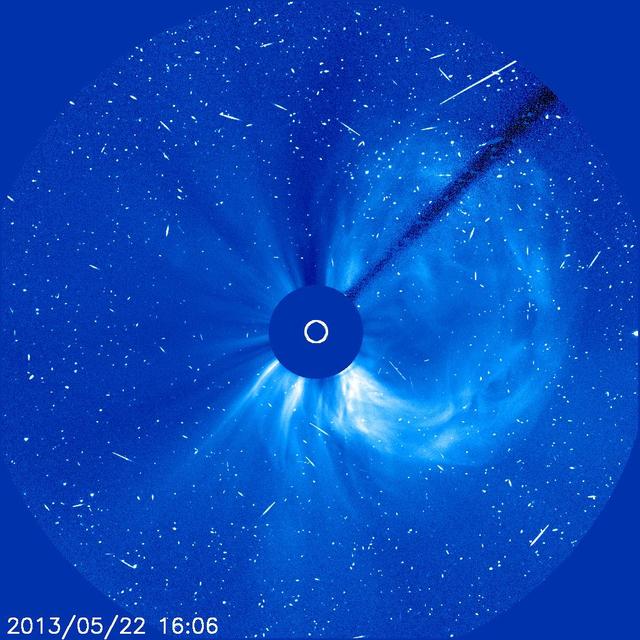
A solar flare associated with the coronal mass ejection seen in this image generated a flurry of fast-moving solar protons. As each one hits the CCD camera on SOHO, it produces a brief snow-like speckle in the image. Credit: NASA/SOHO CME WEEK: What To See in CME Images Two main types of explosions occur on the sun: solar flares and coronal mass ejections. Unlike the energy and x-rays produced in a solar flare – which can reach Earth at the speed of light in eight minutes – coronal mass ejections are giant, expanding clouds of solar material that take one to three days to reach Earth. Once at Earth, these ejections, also called CMEs, can impact satellites in space or interfere with radio communications. During CME WEEK from Sept. 22 to 26, 2014, we explore different aspects of these giant eruptions that surge out from the star we live with. When a coronal mass ejection blasts off the sun, scientists rely on instruments called coronagraphs to track their progress. Coronagraphs block out the bright light of the sun, so that the much fainter material in the solar atmosphere -- including CMEs -- can be seen in the surrounding space. CMEs appear in these images as expanding shells of material from the sun's atmosphere -- sometimes a core of colder, solar material (called a filament) from near the sun's surface moves in the center. But mapping out such three-dimensional components from a two-dimensional image isn't easy. Watch the slideshow to find out how scientists interpret what they see in CME pictures. The images in the slideshow are from the three sets of coronagraphs NASA currently has in space. One is on the joint European Space Agency and NASA Solar and Heliospheric Observatory, or SOHO. SOHO launched in 1995, and sits between Earth and the sun about a million miles away from Earth. The other two coronagraphs are on the two spacecraft of the NASA Solar Terrestrial Relations Observatory, or STEREO, mission, which launched in 2006. The two STEREO spacecraft are both currently viewing the far side of the sun. Together these instruments help scientists create a three-dimensional model of any CME as its journey unfolds through interplanetary space. Such information can show why a given characteristic of a CME close to the sun might lead to a given effect near Earth, or any other planet in the solar system...<b><a href="http://www.nasa.gov/audience/formedia/features/MP_Photo_Guidelines.html" rel="nofollow">NASA image use policy.</a></b> <b><a href="http://www.nasa.gov/centers/goddard/home/index.html" rel="nofollow">NASA Goddard Space Flight Center</a></b> enables NASA’s mission through four scientific endeavors: Earth Science, Heliophysics, Solar System Exploration, and Astrophysics. Goddard plays a leading role in NASA’s accomplishments by contributing compelling scientific knowledge to advance the Agency’s mission. <b>Follow us on <a href="http://twitter.com/NASAGoddardPix" rel="nofollow">Twitter</a></b> <b>Like us on <a href="http://www.facebook.com/pages/Greenbelt-MD/NASA-Goddard/395013845897?ref=tsd" rel="nofollow">Facebook</a></b> <b>Find us on <a href="http://instagram.com/nasagoddard?vm=grid" rel="nofollow">Instagram</a></b>
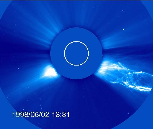
OHO captured this image of a CME from the side – but the structure looks much different from the classic light bulb CME. The filament of material bursting off the sun has a helical magnetic structure, which is unraveling like a piece of yarn during the eruption. Credit: ESA/NASA/SOHO..---..CME WEEK: What To See in CME Images Two main types of explosions occur on the sun: solar flares and coronal mass ejections. Unlike the energy and x-rays produced in a solar flare – which can reach Earth at the speed of light in eight minutes – coronal mass ejections are giant, expanding clouds of solar material that take one to three days to reach Earth. Once at Earth, these ejections, also called CMEs, can impact satellites in space or interfere with radio communications. During CME WEEK from Sept. 22 to 26, 2014, we explore different aspects of these giant eruptions that surge out from the star we live with. When a coronal mass ejection blasts off the sun, scientists rely on instruments called coronagraphs to track their progress. Coronagraphs block out the bright light of the sun, so that the much fainter material in the solar atmosphere -- including CMEs -- can be seen in the surrounding space. CMEs appear in these images as expanding shells of material from the sun's atmosphere -- sometimes a core of colder, solar material (called a filament) from near the sun's surface moves in the center. But mapping out such three-dimensional components from a two-dimensional image isn't easy. Watch the slideshow to find out how scientists interpret what they see in CME pictures. The images in the slideshow are from the three sets of coronagraphs NASA currently has in space. One is on the joint European Space Agency and NASA Solar and Heliospheric Observatory, or SOHO. SOHO launched in 1995, and sits between Earth and the sun about a million miles away from Earth. The other two coronagraphs are on the two spacecraft of the NASA Solar Terrestrial Relations Observatory, or STEREO, mission, which launched in 2006. The two STEREO spacecraft are both currently viewing the far side of the sun. Together these instruments help scientists create a three-dimensional model of any CME as its journey unfolds through interplanetary space. Such information can show why a given characteristic of a CME close to the sun might lead to a given effect near Earth, or any other planet in the solar system...<b><a href="http://www.nasa.gov/audience/formedia/features/MP_Photo_Guidelines.html" rel="nofollow">NASA image use policy.</a></b> <b><a href="http://www.nasa.gov/centers/goddard/home/index.html" rel="nofollow">NASA Goddard Space Flight Center</a></b> enables NASA’s mission through four scientific endeavors: Earth Science, Heliophysics, Solar System Exploration, and Astrophysics. Goddard plays a leading role in NASA’s accomplishments by contributing compelling scientific knowledge to advance the Agency’s mission. <b>Follow us on <a href="http://twitter.com/NASAGoddardPix" rel="nofollow">Twitter</a></b> <b>Like us on <a href="http://www.facebook.com/pages/Greenbelt-MD/NASA-Goddard/395013845897?ref=tsd" rel="nofollow">Facebook</a></b> <b>Find us on <a href="http://instagram.com/nasagoddard?vm=grid" rel="nofollow">Instagram</a></b>
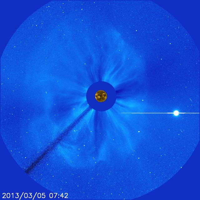
There's no way to tell from this SOHO image whether the halo CME on March 5, 2013, originated from the front or far of the sun. But the STEREO spacecraft were watching the sun from the sides and showed it was from the far side. The bright planet is Venus. Credit: NASA/SOHO CME WEEK: What To See in CME Images Two main types of explosions occur on the sun: solar flares and coronal mass ejections. Unlike the energy and x-rays produced in a solar flare – which can reach Earth at the speed of light in eight minutes – coronal mass ejections are giant, expanding clouds of solar material that take one to three days to reach Earth. Once at Earth, these ejections, also called CMEs, can impact satellites in space or interfere with radio communications. During CME WEEK from Sept. 22 to 26, 2014, we explore different aspects of these giant eruptions that surge out from the star we live with. When a coronal mass ejection blasts off the sun, scientists rely on instruments called coronagraphs to track their progress. Coronagraphs block out the bright light of the sun, so that the much fainter material in the solar atmosphere -- including CMEs -- can be seen in the surrounding space. CMEs appear in these images as expanding shells of material from the sun's atmosphere -- sometimes a core of colder, solar material (called a filament) from near the sun's surface moves in the center. But mapping out such three-dimensional components from a two-dimensional image isn't easy. Watch the slideshow to find out how scientists interpret what they see in CME pictures. The images in the slideshow are from the three sets of coronagraphs NASA currently has in space. One is on the joint European Space Agency and NASA Solar and Heliospheric Observatory, or SOHO. SOHO launched in 1995, and sits between Earth and the sun about a million miles away from Earth. The other two coronagraphs are on the two spacecraft of the NASA Solar Terrestrial Relations Observatory, or STEREO, mission, which launched in 2006. The two STEREO spacecraft are both currently viewing the far side of the sun. Together these instruments help scientists create a three-dimensional model of any CME as its journey unfolds through interplanetary space. Such information can show why a given characteristic of a CME close to the sun might lead to a given effect near Earth, or any other planet in the solar system...<b><a href="http://www.nasa.gov/audience/formedia/features/MP_Photo_Guidelines.html" rel="nofollow">NASA image use policy.</a></b> <b><a href="http://www.nasa.gov/centers/goddard/home/index.html" rel="nofollow">NASA Goddard Space Flight Center</a></b> enables NASA’s mission through four scientific endeavors: Earth Science, Heliophysics, Solar System Exploration, and Astrophysics. Goddard plays a leading role in NASA’s accomplishments by contributing compelling scientific knowledge to advance the Agency’s mission. <b>Follow us on <a href="http://twitter.com/NASAGoddardPix" rel="nofollow">Twitter</a></b> <b>Like us on <a href="http://www.facebook.com/pages/Greenbelt-MD/NASA-Goddard/395013845897?ref=tsd" rel="nofollow">Facebook</a></b> <b>Find us on <a href="http://instagram.com/nasagoddard?vm=grid" rel="nofollow">Instagram</a></b>