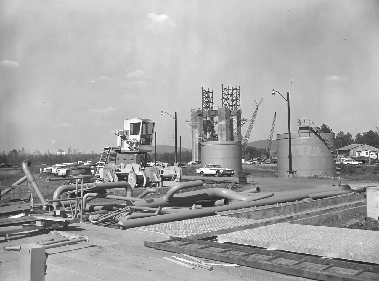
At its founding, the Marshall Space Flight Center (MSFC) inherited the Army’s Jupiter and Redstone test stands, but much larger facilities were needed for the giant stages of the Saturn V. From 1960 to 1964, the existing stands were remodeled and a sizable new test area was developed. The new comprehensive test complex for propulsion and structural dynamics was unique within the nation and the free world, and they remain so today because they were constructed with foresight to meet the future as well as on going needs. Construction of the S-IC Static test stand complex began in 1961 in the west test area of MSFC, and was completed in 1964. The S-IC static test stand was designed to develop and test the 138-ft long and 33-ft diameter Saturn V S-IC first stage, or booster stage, weighing in at 280,000 pounds. Required to hold down the brute force of a 7,500,000-pound thrust produced by 5 F-1 engines, the S-IC static test stand was designed and constructed with the strength of hundreds of tons of steel and 12,000,000 pounds of cement, planted down to bedrock 40 feet below ground level. The foundation walls, constructed with concrete and steel, are 4 feet thick. The base structure consists of four towers with 40-foot-thick walls extending upward 144 feet above ground level. The structure was topped by a crane with a 135-foot boom. With the boom in the upright position, the stand was given an overall height of 405 feet, placing it among the highest structures in Alabama at the time. In addition to the stand itself, related facilities were constructed during this time. Northeast of the massive S-IC test stand, the F-1 Engine test stand was built. The F-1 test stand is a vertical engine firing test stand, 239 feet in elevation and 4,600 square feet in area at the base, and was designed to assist in the development of the F-1 Engine. Capability was provided for static firing of 1.5 million pounds of thrust using liquid oxygen and kerosene. Like the S-IC stand, the foundation of the F-1 stand is keyed into the bedrock approximately 40 feet below grade. This photo depicts the fuel tanks that housed kerosene and just beyond those is the F-1 test stand.
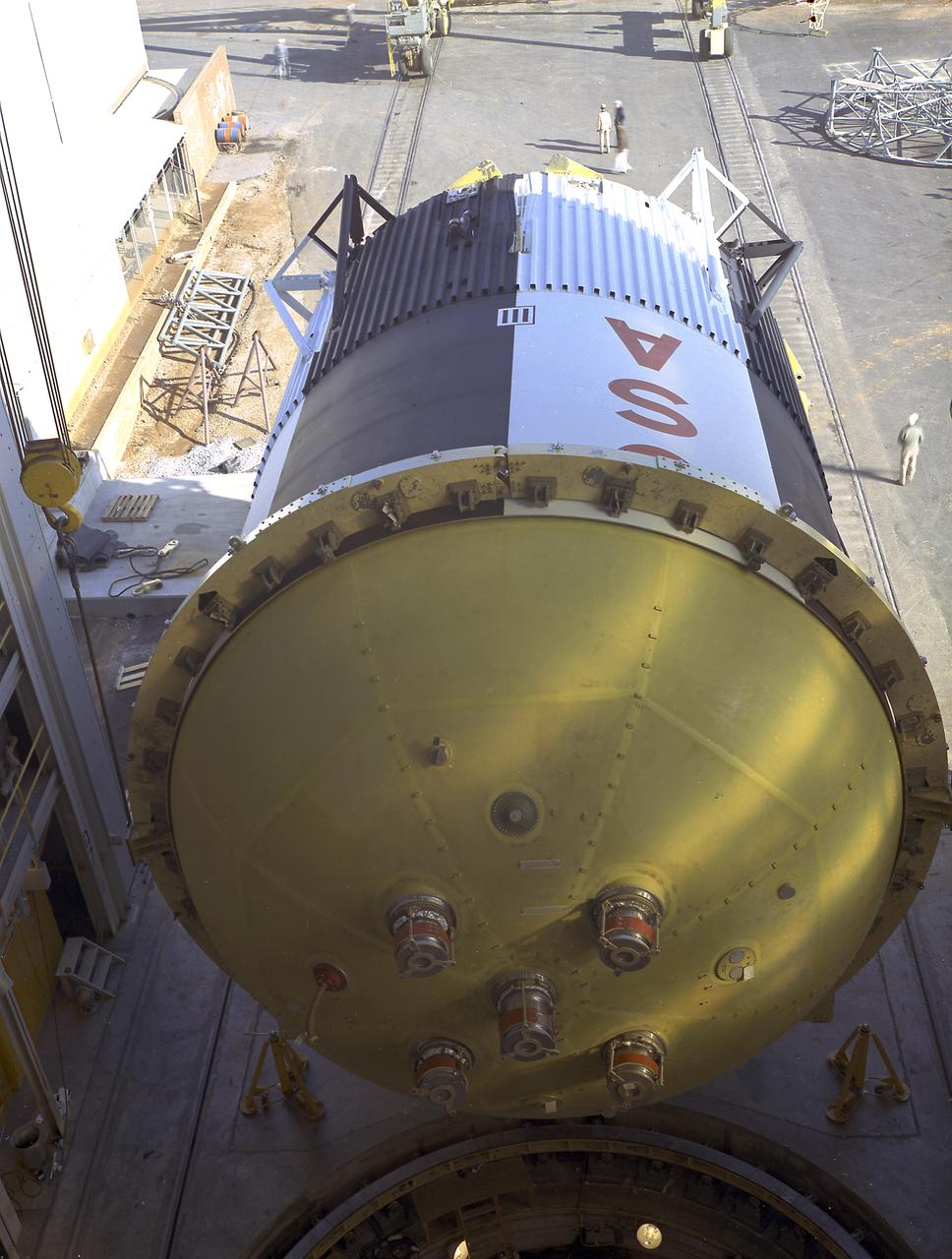
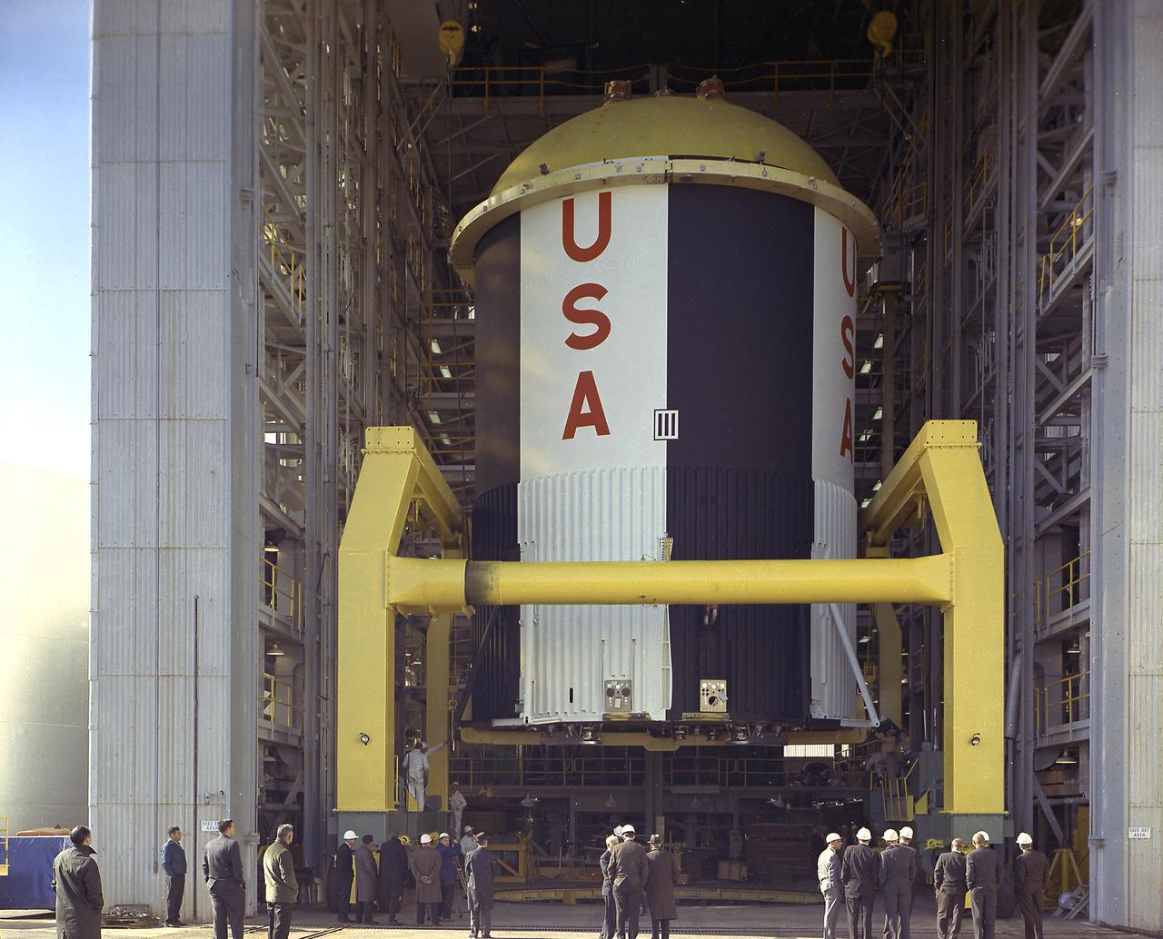
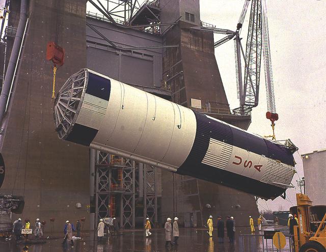
The fuel tank assembly of the Saturn V S-IC (first) stage is readied to be mated to the liquid oxygen tank at the Marshall Space Flight Center. The fuel tank carried kerosene as its fuel. The S-IC stage utilized five F-1 engines that used kerosene and liquid oxygen as propellant. Each engine provided 1,500,000 pounds of thrust. This stage lifted the entire vehicle and Apollo spacecraft from the launch pad.
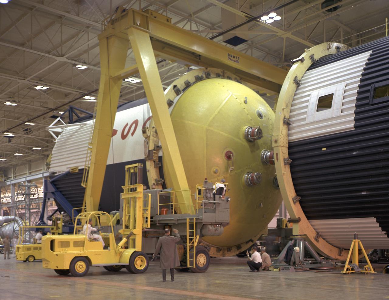
This photograph shows how the fuel tank assembly and the liquid oxygen tank for the Saturn V S-IC (first) stage are placed side by side prior to commencement of the mating of the two stages in the Marshall Space Flight Center, building 4705. The fuel tank carried kerosene as its fuel. The S-IC stage used five F-1 engines, that used kerosene and liquid oxygen as propellant and each engine provided 1,500,000 pounds of thrust. This stage lifted the entire vehicle and Apollo spacecraft from the launch pad.
The fuel tank assembly for the Saturn V S-IC (first) stage arrived at the Marshall Space Flight Center, building 4707, for mating to the liquid oxygen tank. The fuel tank carried kerosene as its fuel. The S-IC stage used five F-1 engines, that used kerosene and liquid oxygen as propellant and each engine provided 1,500,000 pounds of thrust. This stage lifted the entire vehicle and Apollo spacecraft from the launch pad.
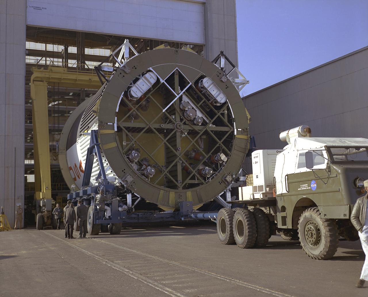
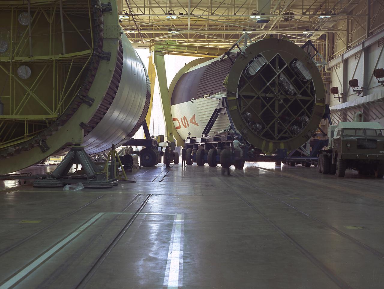
This photograph shows the fuel tank assembly for the Saturn V S-IC (first) stage being transported to the Marshall Space Flight Center, building 4705 for mating to the liquid oxygen (LOX) tank. The fuel tank carried kerosene (RP-1) as its fuel. The S-IC stage used five F-1 engines, that used kerosene and liquid oxygen as propellant and each engine provided 1,500,000 pounds of thrust. This stage lifted the entire vehicle and Apollo spacecraft from the launch pad.
The fuel tank assembly of the Saturn V S-IC (first) stage supported with the aid of a C frame on the transporter was readied to be transported to the Marshall Space Flight Center, building 4705. The fuel tank carried kerosene (RP-1) as its fuel. The S-IC stage utilized five F-1 engines that used kerosene and liquid oxygen as propellant and each engine provided 1,500,000 pounds of thrust. This stage lifted the entire vehicle and Apollo spacecraft from the launch pad.
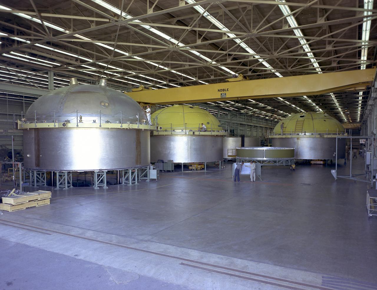
The components of the Saturn V booster (S-IC stage) fuel tank are shown in this photograph. The liquid oxygen tank bulkhead on the left and both halves of the fuel tank were in the Marshall Space Flight Center (MSFC) Manufacturing Engineering Laboratory, building 4707. These components were used at MSFC in structural testing to prove that they could withstand the forces to which they were subjected in flight. Each S-IC stage has two tanks, one for kerosene and one for liquid oxygen, made from such components as these. Thirty-three feet in diameter, they hold a total of 4,400,000 pounds of fuel. Although this tankage was assembled at MSFC, the elements were made by the Boeing Company at Wichita and the Michoud Operations at New Orleans.
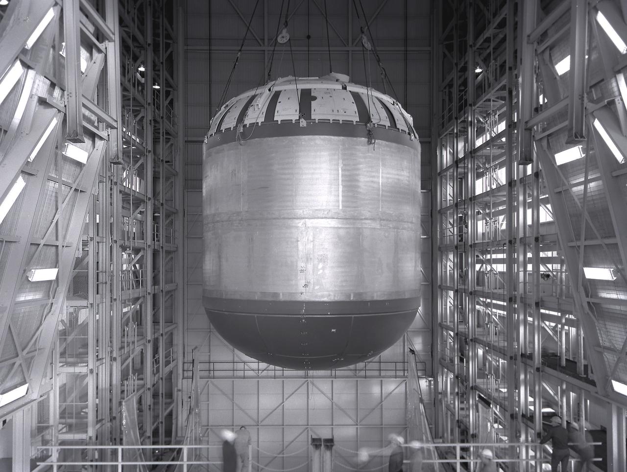
Marshall Space Flight Center successfully conducted hydrostatic testing on the Saturn V S-IC (first) stage fuel tank. The first stage was powered by five F-1 engines, that used liquid oxygen and kerosene as its propellant.
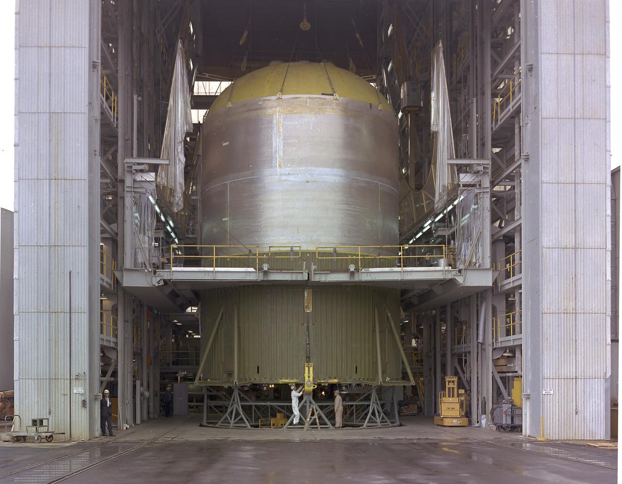
This image shows the Saturn V S-IC-T stage (S-IC static test article) fuel tank being attached to the thrust structure in the vehicle assembly building at the Marshall Space Flight Center (MSFC). The S-IC stage utilized five F-1 engines that used liquid oxygen and kerosene as propellant and provided a combined thrust of 7,500,000 pounds.
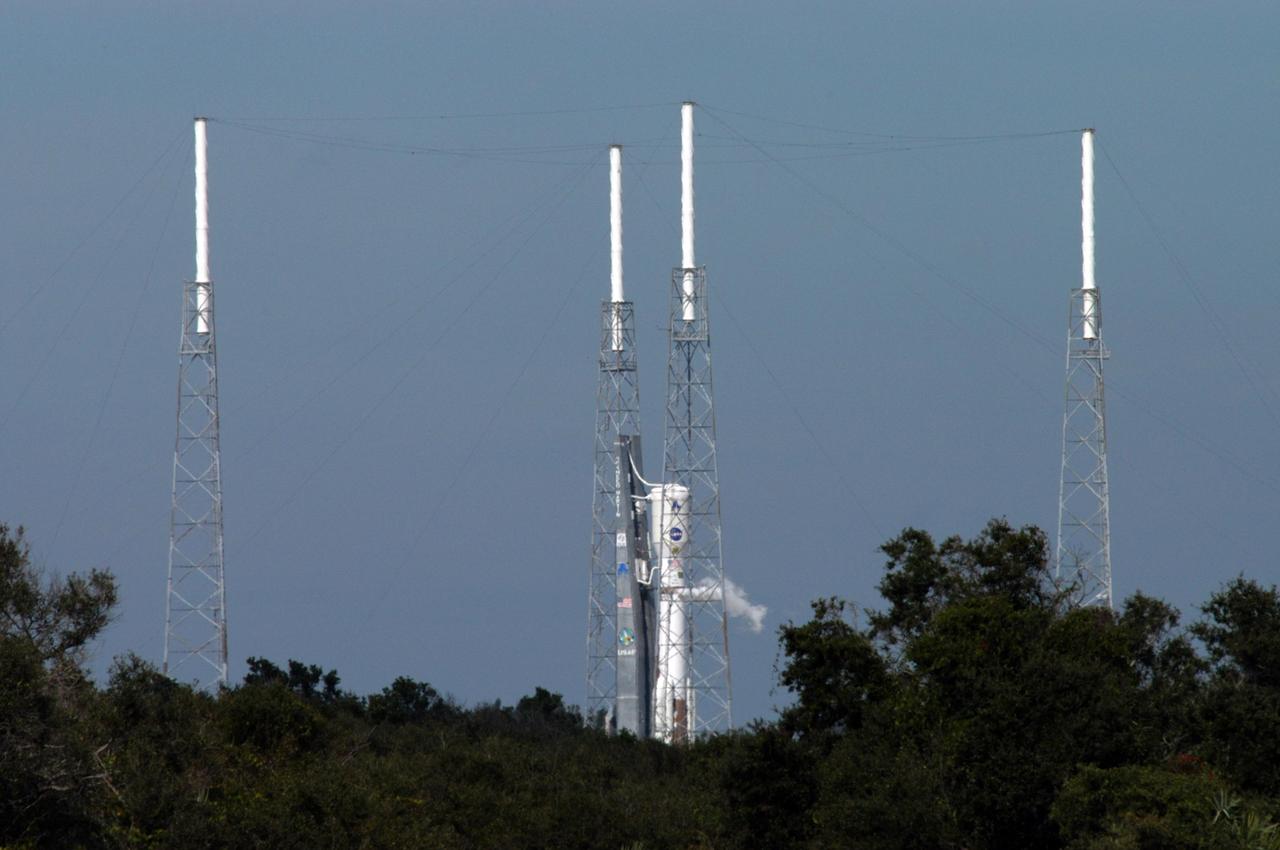
KENNEDY SPACE CENTER, FLA. - The Lockheed Martin Atlas V rocket (center) undergoes a tanking test on Launch Complex 41 at Cape Canaveral Air Force Station in Florida. The rocket was fully fueled with liquid hydrogen, liquid oxygen and RP 1 kerosene fuel. Seen surrounding the rocket are lightning towers that support the catenary wire that provides lightning protection. The Atlas V is the launch vehicle for NASA’s New Horizons spacecraft, scheduled to launch during a 35-day window that opens Jan. 11, and fly through the Pluto system as early as summer 2015.
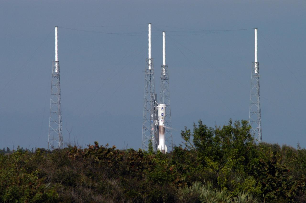
KENNEDY SPACE CENTER, FLA. - The Lockheed Martin Atlas V rocket (center) undergoes a tanking test on Launch Complex 41 at Cape Canaveral Air Force Station in Florida. The rocket was fully fueled with liquid hydrogen, liquid oxygen and RP 1 kerosene fuel. Seen surrounding the rocket are lightning towers that support the catenary wire that provides lightning protection. The Atlas V is the launch vehicle for NASA’s New Horizons spacecraft, scheduled to launch during a 35-day window that opens Jan. 11, and fly through the Pluto system as early as summer 2015.
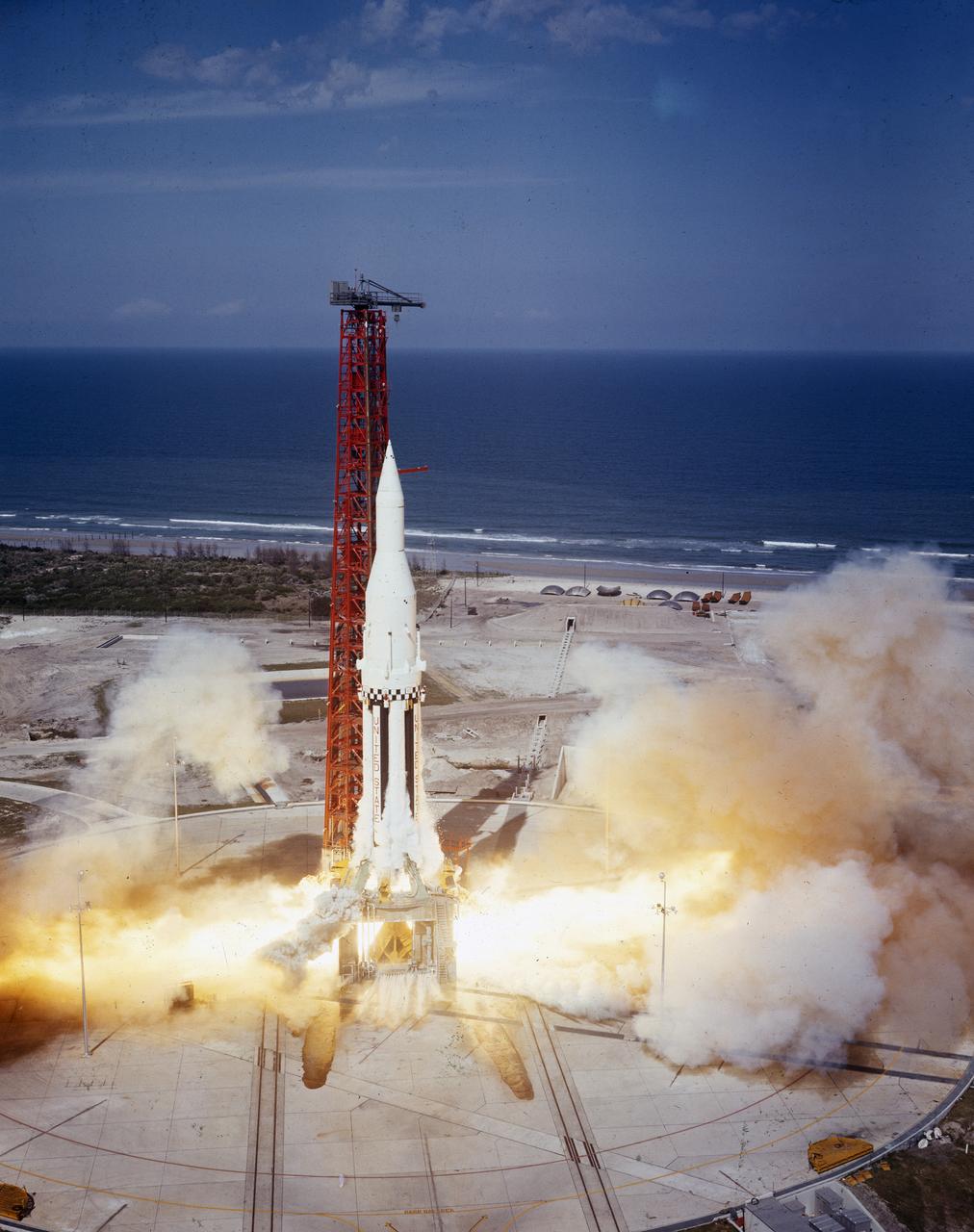
The Saturn I (SA-4) flight lifted off from Kennedy Space Center launch Complex 34, March 28, 1963. The fourth launch of Saturn launch vehicles developed at the Marshall Space Flight Center (MSFC), under the direction of Dr. Wernher von Braun, incorporated a Saturn I, Block I engine. The typical height of a Block I vehicle was approximately 163 feet and had only one live stage. It consisted of eight tanks, each 70 inches in diameter, clustered around a central tank, 105 inches in diameter. Four of the external tanks were fuel tanks for the RP-1 (kerosene) fuel. The other four, spaced alternately with the fuel tanks, were liquid oxygen tanks as was the large center tank. All fuel tanks and liquid oxygen tanks drained at the same rates respectively. The thrust for the stage came from eight H-1 engines, each producing a thrust of 165,000 pounds, for a total thrust of over 1,300,000 pounds. The engines were arranged in a double pattern. Four engines, located inboard, were fixed in a square pattern around the stage axis and canted outward slightly, while the remaining four engines were located outboard in a larger square pattern offset 40 degrees from the inner pattern. Unlike the inner engines, each outer engine was gimbaled. That is, each could be swung through an arc. They were gimbaled as a means of steering the rocket, by letting the instrumentation of the rocket correct any deviations of its powered trajectory. The block I required engine gimabling as the only method of guiding and stabilizing the rocket through the lower atmosphere. The upper stages of the Block I rocket reflected the three-stage configuration of the Saturn I vehicle. Like SA-3, the SA-4 flight’s upper stage ejected 113,560 liters (30,000 gallons) of ballast water in the upper atmosphere for "Project Highwater" physics experiment. Release of this vast quantity of water in a near-space environment marked the second purely scientific large-scale experiment. The SA-4 was the last Block I rocket launch.
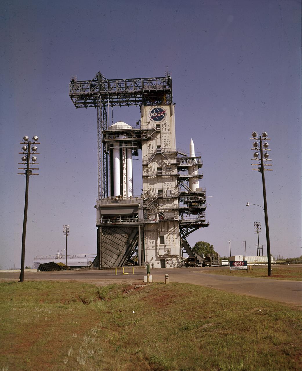
On October 27, 1961, the Marshall Space Flight Center (MSFC) and the Nation marked a high point in the 3-year-old Saturn development program when the first Saturn vehicle flew a flawless 215-mile ballistic trajectory from Cape Canaveral, Florida. SA-1 is pictured here, five months before launch, in the MSFC test stand on May 16, 1961. Developed and tested at MSFC under the direction of Dr. Wernher von Braun, SA-1 incorporated a Saturn I, Block I engine. The typical height of a Block I vehicle was approximately 163 feet. and had only one live stage. It consisted of eight tanks, each 70 inches in diameter, clustered around a central tank, 105 inches in diameter. Four of the external tanks were fuel tanks for the RP-1 (kerosene) fuel. The other four, spaced alternately with the fuel tanks, were liquid oxygen tanks, as was the large center tank. All fuel tanks and liquid oxygen tanks drained at the same rates respectively. The thrust for the stage came from eight H-1 engines, each producing a thrust of 165,000 pounds, for a total thrust of over 1,300,000 pounds. The engines were arranged in a double pattern. Four engines, located inboard, were fixed in a square pattern around the stage axis and canted outward slightly, while the remaining four engines were located outboard in a larger square pattern offset 40 degrees from the inner pattern. Unlike the inner engines, each outer engine was gimbaled. That is, each could be swung through an arc. They were gimbaled as a means of steering the rocket, by letting the instrumentation of the rocket correct any deviations of its powered trajectory. The block I required engine gimabling as the only method of guiding and stabilizing the rocket through the lower atmosphere. The upper stages of the Block I rocket reflected the three-stage configuration of the Saturn I vehicle.
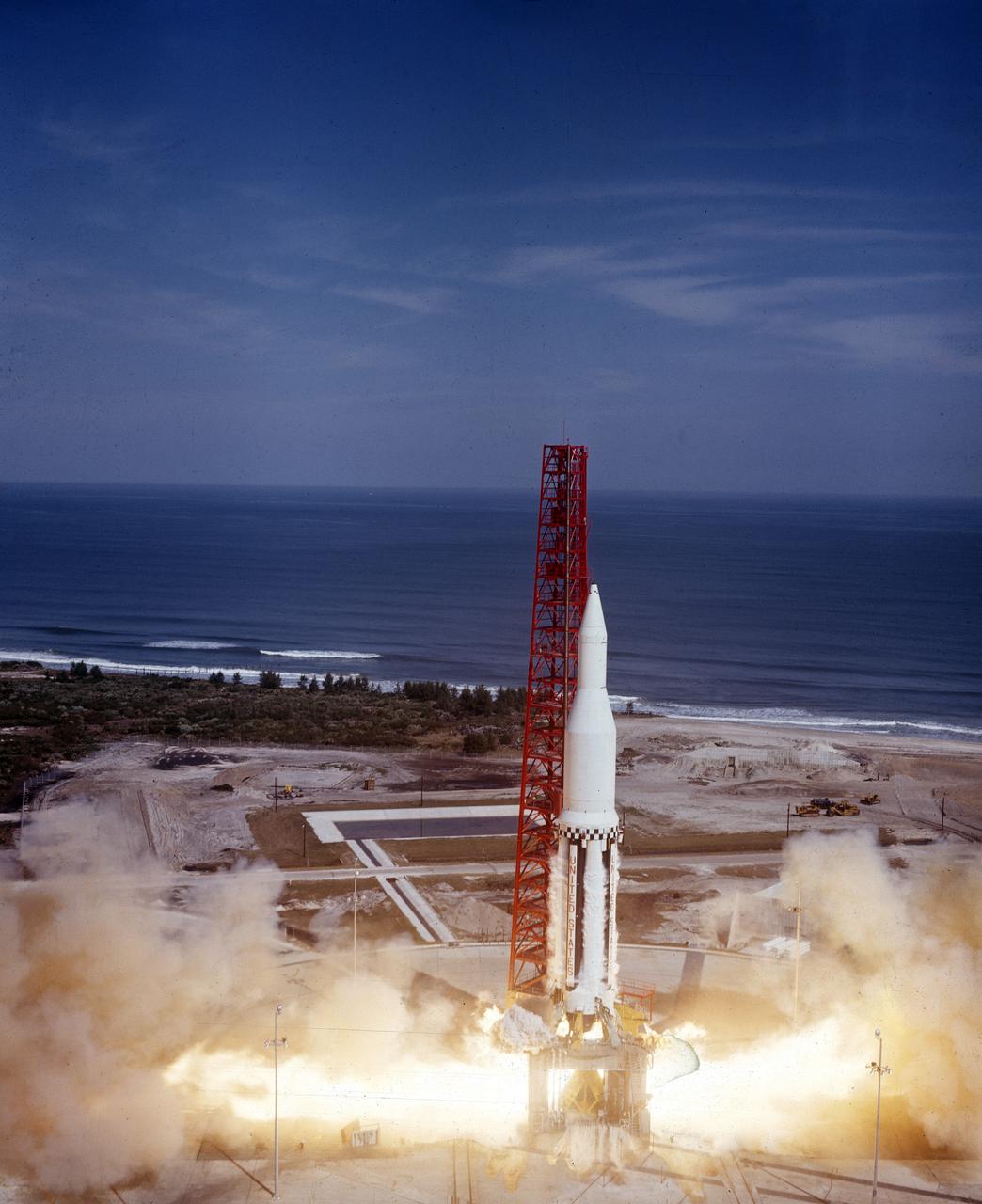
The Saturn I (SA-3) flight lifted off from Kennedy Space Center launch Complex 34, November 16, 1962. The third launch of Saturn launch vehicles, developed at the Marshall Space Flight Center (MSFC) under the direction of Dr. Wernher von Braun, incorporated a Saturn I, Block I engine. The typical height of a Block I vehicle was approximately 163 feet. and had only one live stage. It consisted of eight tanks, each 70 inches in diameter, clustered around a central tank, 105 inches in diameter. Four of the external tanks were fuel tanks for the RP-1 (kerosene) fuel. The other four, spaced alternately with the fuel tanks, were liquid oxygen tanks as was the large center tank. All fuel tanks and liquid oxygen tanks drained at the same rates respectively. The thrust for the stage came from eight H-1 engines, each producing a thrust of 165,000 pounds, for a total thrust of over 1,300,000 pounds. The engines were arranged in a double pattern. Four engines, located inboard, were fixed in a square pattern around the stage axis and canted outward slightly, while the remaining four engines were located outboard in a larger square pattern offset 40 degrees from the inner pattern. Unlike the inner engines, each outer engine was gimbaled. That is, each could be swung through an arc. They were gimbaled as a means of steering the rocket, by letting the instrumentation of the rocket correct any deviations of its powered trajectory. The block I required engine gimabling as the only method of guiding and stabilizing the rocket through the lower atmosphere. The upper stages of the Block I rocket reflected the three-stage configuration of the Saturn I vehicle. During the SA-3 flight, the upper stage ejected 113,560 liters (30,000 gallons) of ballast water in the upper atmosphere for "Project Highwater" physics experiment. The water was released at an altitude of 65 miles, where within only 5 seconds, it expanded into a massive ice cloud 4.6 miles in diameter. Release of this vast quantity of water in a near-space environment marked the first purely scientific large-scale experiment.
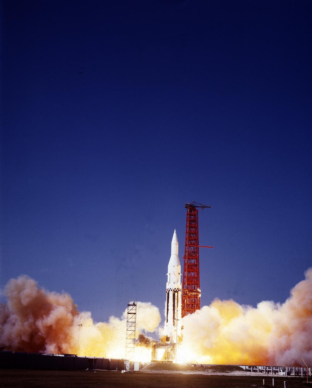
The Saturn I (SA-4) flight lifted off from Kennedy Space Center launch Complex 34, March 28, 1963. The fourth launch of Saturn launch vehicles, developed at the Marshall Space Flight Center (MSFC) under the direction of Dr. Wernher von Braun, incorporated a Saturn I, Block I engine. The typical height of a Block I vehicle was approximately 163 feet and had only one live stage. It consisted of eight tanks, each 70 inches in diameter, clustered around a central tank, 105 inches in diameter. Four of the external tanks were fuel tanks for the RP-1 (kerosene) fuel. The other four, spaced alternately with the fuel tanks, were liquid oxygen tanks as was the large center tank. All fuel tanks and liquid oxygen tanks drained at the same rates respectively. The thrust for the stage came from eight H-1 engines, each producing a thrust of 165,000 pounds, for a total thrust of over 1,300,000 pounds. The engines were arranged in a double pattern. Four engines, located inboard, were fixed in a square pattern around the stage axis and canted outward slightly, while the remaining four engines were located outboard in a larger square pattern offset 40 degrees from the inner pattern. Unlike the inner engines, each outer engine was gimbaled. That is, each could be swung through an arc. They were gimbaled as a means of steering the rocket, by letting the instrumentation of the rocket correct any deviations of its powered trajectory. The block I required engine gimabling as the only method of guiding and stabilizing the rocket through the lower atmosphere. The upper stages of the Block I rocket reflected the three-stage configuration of the Saturn I vehicle. Like SA-3, the SA-4 flight’s upper stage ejected 113,560 liters (30,000 gallons) of ballast water in the upper atmosphere for "Project Highwater" physics experiment. Release of this vast quantity of water in a near-space environment marked the second purely scientific large-scale experiment. The SA-4 was the last Block I rocket launch.
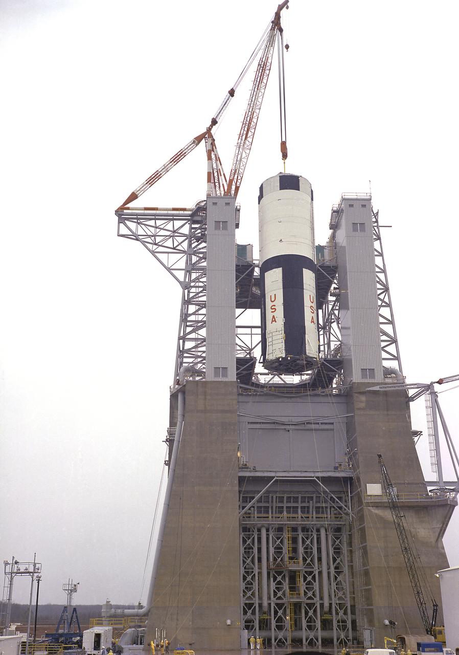
The S-IC-T stage is hoisted into the S-IC static test stand at the Marshall Space Flight Center. The S-IC-T stage is a static test vehicle not intended for flight. It was ground tested repeatedly over a period of many months proving the vehicle's propulsion system. The 280,000-pound stage, 138 feet long and 33 feet in diameter, houses the fuel and liquid oxygen tanks that hold a total of 4,400,000 pounds of liquid oxygen and kerosene. The two tanks are cornected by a 26-foot-long intertank section. Other parts of the booster included the forward skirt and the thrust structure, on which the engines were to be mounted. Five F-1 engines, each weighing 10 tons, gave the booster a total thrust of 7,500,000 pounds, roughly equivalent to 160 million horsepower.
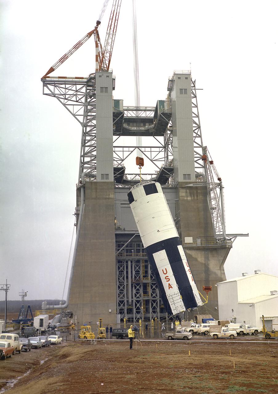
The S-IC-T stage was hoisted into the S-IC static test stand at the Marshall Space Flight Center. The S-IC-T stage was a static test vehicle not intended for flight. It was ground tested repeatedly over a period of many months to prove the vehicle's propulsion system. The 280,000-pound stage, 138 feet long and 33 feet in diameter, housed the fuel and liquid oxygen tanks that held a total of 4,400,000 pounds of liquid oxygen and kerosene. The two tanks are cornected by a 26-foot-long intertank section. Other parts of the booster included the forward skirt and the thrust structure, on which the engines were to be mounted. Five F-1 engines, each weighing 10 tons, gave the booster a total thrust of 7,500,000 pounds, roughly equivalent to 160 million horsepower.
The S-IC-T stage was hoisted into the S-IC Static Test Stand at the Marshall Space Flight Center. The S-IC-T stage was a static test vehicle, not intended for flight. It was ground tested repeatedly over a period of many months to prove the vehicle's propulsion system. The 280,000-pound stage, 138 feet long and 33 feet in diameter, housed the fuel and liquid oxygen tanks that held a total of 4,400,000 pounds of liquid oxygen and kerosene. The two tanks were cornected by a 26-foot intertank section. Other parts of the booster included the forward skirt and the thrust structure, on which the engines were to be mounted. Five F-1 engines, each weighing 10 tons, gave the booster a total thrust of 7,500,000 pounds, roughly equivalent to 160 million horsepower.
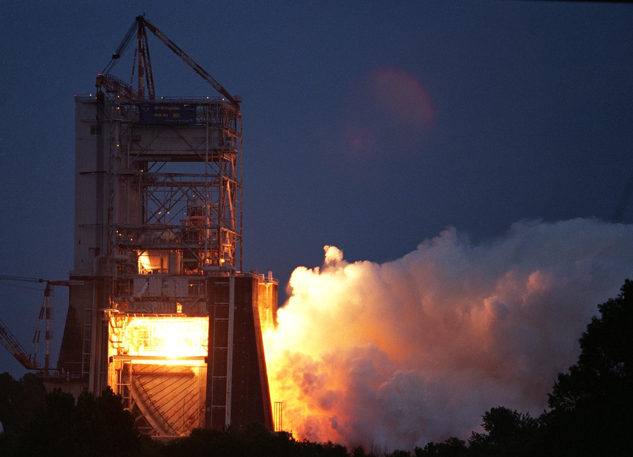
NASA engineers successfully tested a Russian-built rocket engine on November 4, 1998 at the Marshall Space Flight Center (MSFC) Advanced Engine Test Facility, which had been used for testing the Saturn V F-1 engines and Space Shuttle Main engines. The MSFC was under a Space Act Agreement with Lockheed Martin Astronautics of Denver to provide a series of test firings of the Atlas III propulsion system configured with the Russian-designed RD-180 engine. The tests were designed to measure the performance of the Atlas III propulsion system, which included avionics and propellant tanks and lines, and how these components interacted with the RD-180 engine. The RD-180 is powered by kerosene and liquid oxygen, the same fuel mix used in Saturn rockets. The RD-180, the most powerful rocket engine tested at the MSFC since Saturn rocket tests in the 1960s, generated 860,000 pounds of thrust.