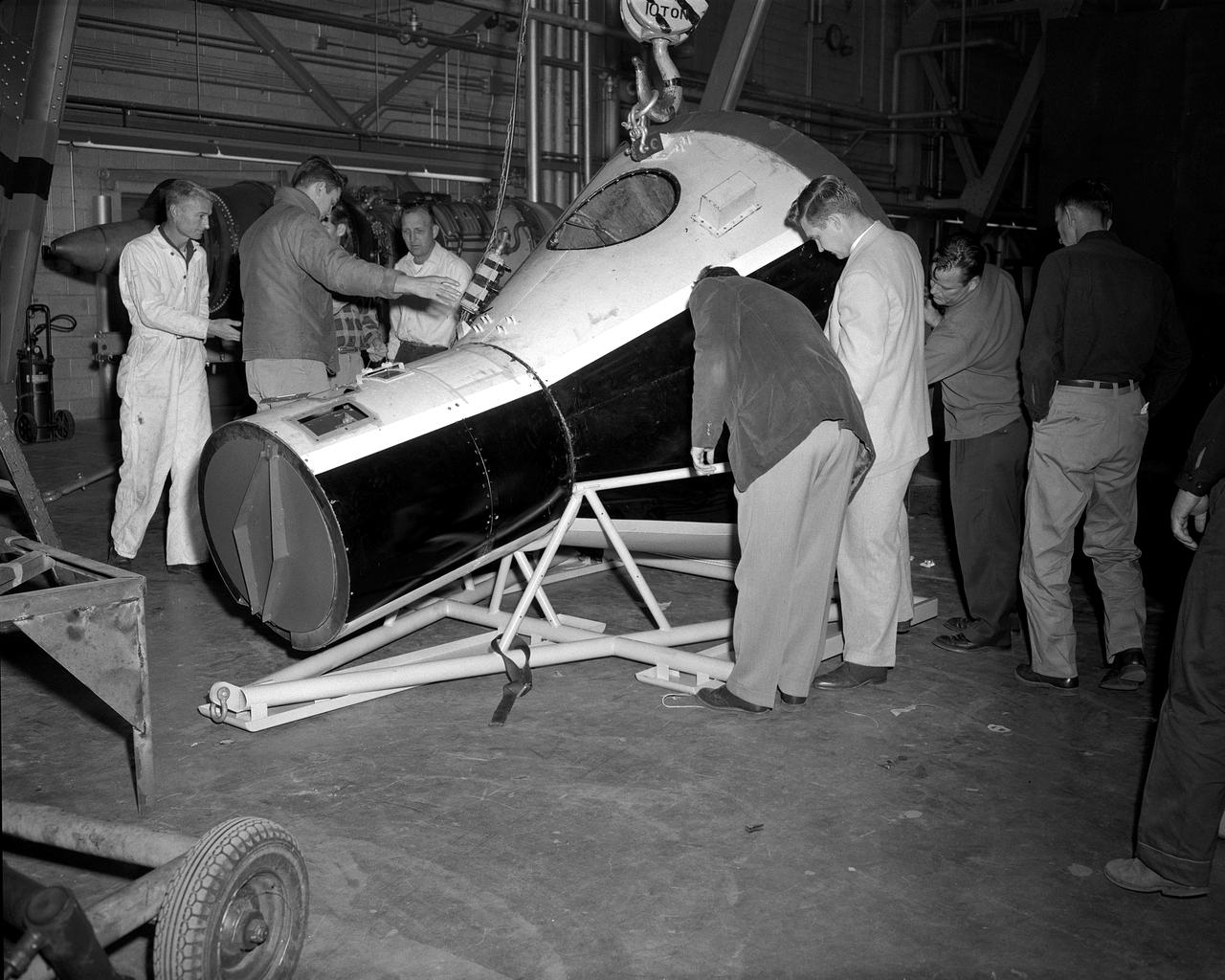
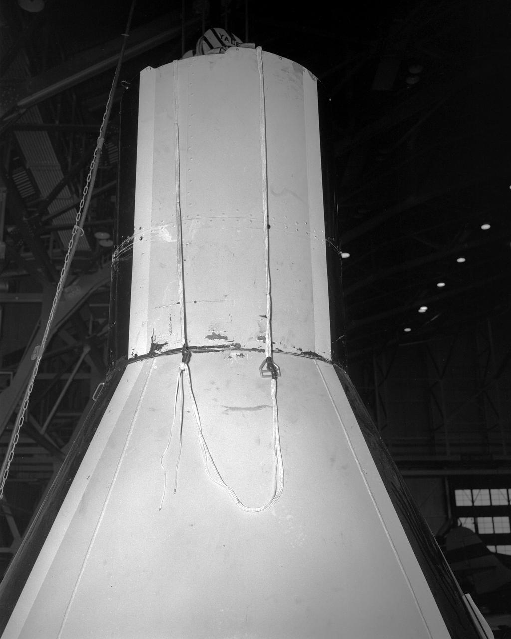
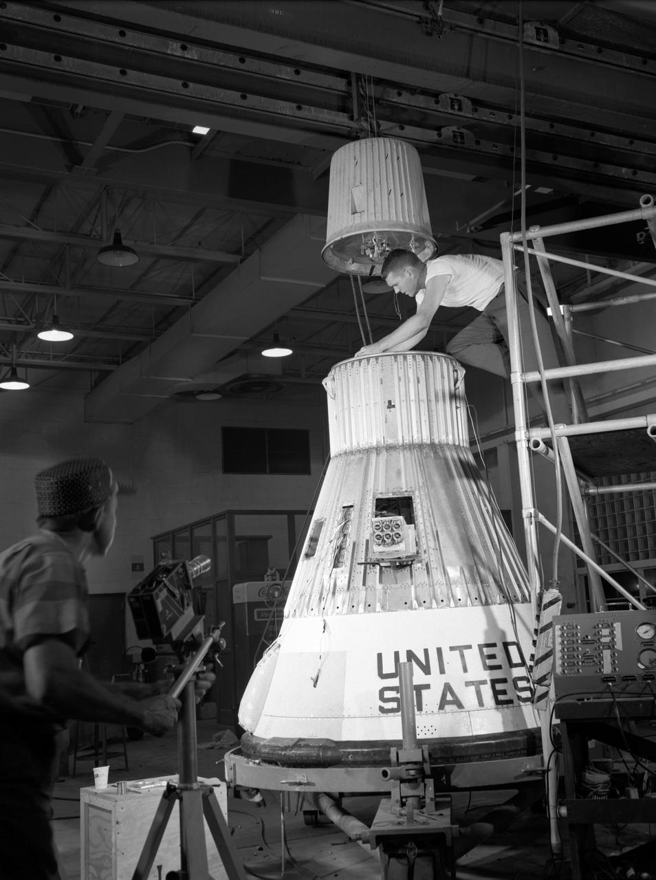
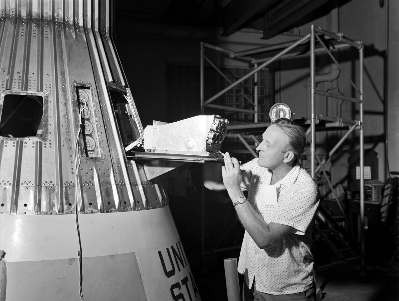
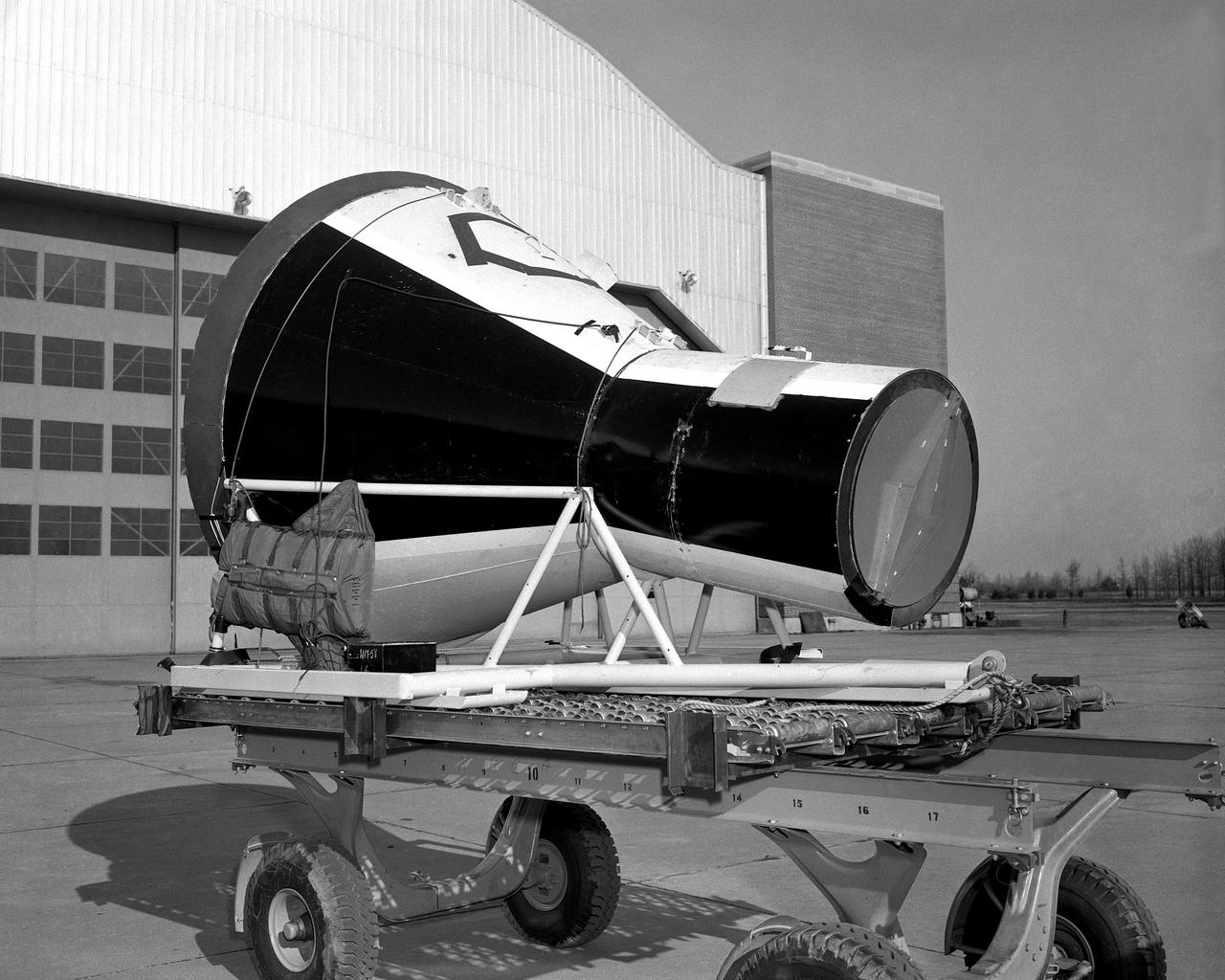
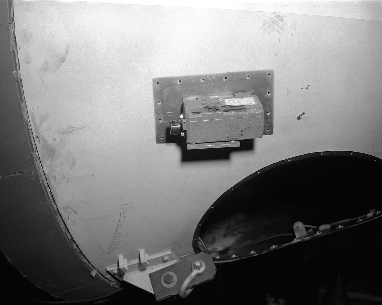
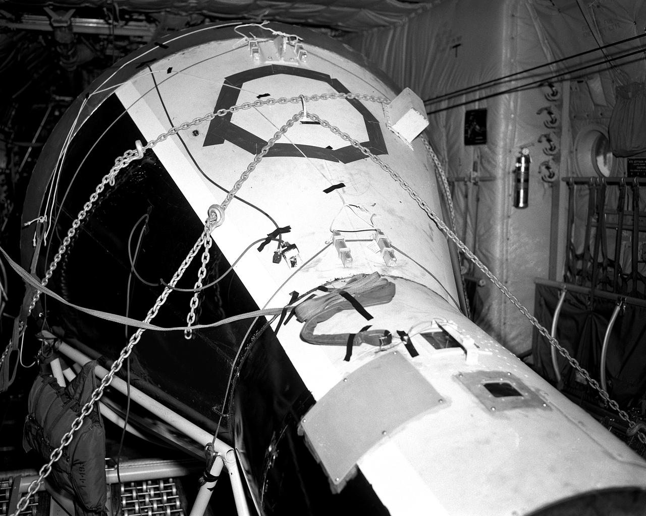
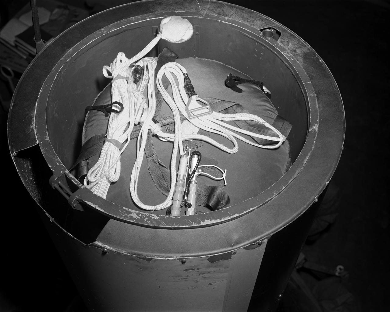
This image (captured from animation video) illustrates the separation of the X-43A research vehicle from the Pegasus booster. (LaRC Photo # EL-2000-00532)
This image (captured from animation video) illustrates the X-43A research vehicle alone after separation from the Pegasus booster. (LaRC Photo # EL-2000-00531)
Hybrid Wing Body Particle Image Velocimetry Test in LaRC 14x22 Foot Tunnel: PIV measurement of HWB-N2A model in Langley 14x22 Foot Tunnel
Hybrid Wing Body Particle Image Velocimetry Test in LaRC 14x22 F
Hybrid Wing Body Particle Image Velocimetry Test in LaRC 14x22 Foot Tunnel: PIV measurement of HWB-N2A model in Langley 14x22 Foot Tunnel
Hybrid Wing Body Particle Image Velocimetry Test in LaRC 14x22 F
Hybrid Wing Body Particle Image Velocimetry Test in LaRC 14x22 Foot Tunnel: PIV measurement of HWB-N2A model in Langley 14x22 Foot Tunnel
Hybrid Wing Body Particle Image Velocimetry Test in LaRC 14x22 F
Hybrid Wing Body Particle Image Velocimetry Test in LaRC 14x22 Foot Tunnel: PIV measurement of HWB-N2A model in Langley 14x22 Foot Tunnel
Hybrid Wing Body Particle Image Velocimetry Test in LaRC 14x22 F
Hybrid Wing Body Particle Image Velocimetry Test in LaRC 14x22 Foot Tunnel: PIV measurement of HWB-N2A model in Langley 14x22 Foot Tunnel
Hybrid Wing Body Particle Image Velocimetry Test in LaRC 14x22 F
Hybrid Wing Body Particle Image Velocimetry Test in LaRC 14x22 Foot Tunnel: PIV measurement of HWB-N2A model in Langley 14x22 Foot Tunnel
Hybrid Wing Body Particle Image Velocimetry Test in LaRC 14x22 F
Hybrid Wing Body Particle Image Velocimetry Test in LaRC 14x22 Foot Tunnel: PIV measurement of HWB-N2A model in Langley 14x22 Foot Tunnel
Hybrid Wing Body Particle Image Velocimetry Test in LaRC 14x22 F
0.4% Scale (SLS) Space Launch System Model Test In NASA LaRC Unitary Plan Wind Tunnel
0.4% Scale (SLS) Space Launch System Model Test In NASA LaRC Uni
0.4% Scale (SLS) Space Launch System Model Test In NASA LaRC Unitary Plan Wind Tunnel
0.4% Scale (SLS) Space Launch System Model Test In NASA LaRC Uni
0.4% Scale (SLS) Space Launch System Model Test In NASA LaRC Unitary Plan Wind Tunnel
0.4% Scale (SLS) Space Launch System Model Test In NASA LaRC Uni
0.4% Scale (SLS) Space Launch System Model Test In NASA LaRC Unitary Plan Wind Tunnel
0.4% Scale (SLS) Space Launch System Model Test In NASA LaRC Uni
0.4% Scale (SLS) Space Launch System Model Test In NASA LaRC Unitary Plan Wind Tunnel
0.4% Scale (SLS) Space Launch System Model Test In NASA LaRC Uni
0.4% Scale (SLS) Space Launch System Model Test In NASA LaRC Unitary Plan Wind Tunnel
0.4% Scale (SLS) Space Launch System Model Test In NASA LaRC Uni
MARK HILBURGER, PROJECT ENGINEER FROM LANGLEY RESEARCH CENTER (LARC) WITH THE ALUMINUM-LITHIUM CYLINDER USED IN THE SHELL BUCKLE KNOCKDOWN FACTOR TESTING. DURING THE TESTING FORCE AND PRESSURE WERE INCREASINGLY APPLIED TO THE TOP OF AN EMPTY BUT PRESSURIZED ROCKET FUEL TANK TO EVALUATE ITS STRUCTURAL INTEGRITY.
1301259
NASA's Hyper-x Program Manager, Vince Rausch talks about the upcoming launch of the X43A vehicle over the Pacific Ocean later this month from his office at NASA Langley Research Center in Hampton, VA.  Hyper X is a high risk, high payoff program.  The flight of the X43 A will demonstrated in flight for the first time, air breathing hypersonic propulsion technology. (Photo by Jeff Caplan)
X43 Hyper-X
Vertical model flying in Langley Research Center's Full Scale Tunnel.
Vertical model flying in LaRC Full Scale Tunnel
Vertical model flying in Langley Research Center's Full Scale Tunnel.
Vertical model flying in LaRC Full Scale Tunnel
Vertical model flying in Langley Research Center's Full Scale Tunnel.
Vertical model flying in LaRC Full Scale Tunnel
LaRC aircraft in front of hangar, building 1244
Aircraft in front of hangar
Astronaut Virgil "Gus" Grissom at the controls of the Visual Docking Simulator. From A.W. Vogeley, "Piloted Space-Flight Simulation at Langley Research Center," Paper presented at the American Society of Mechanical Engineers 1966 Winter Meeting, New York, NY, November 27-December 1, 1966. "This facility was [later known as the Visual-Optical Simulator.] It presents to the pilot an out-the-window view of his target in correct 6 degrees of freedom motion. The scene is obtained by a television camera pick-up viewing a small-scale gimbaled model of the target." "For docking studies, the docking target picture was projected onto the surface of a 20-foot-diameter sphere and the pilot could, effectively, maneuver into contract. this facility was used in a comparison study with the Rendezvous Docking Simulator - one of the few comparison experiments in which conditions were carefully controlled and a reasonable sample of pilots used. All pilots preferred the more realistic RDS visual scene. The pilots generally liked the RDS angular motion cues although some objected to the false gravity cues that these motions introduced. Training time was shorter on the RDS, but final performance on both simulators was essentially equal. " "For station-keeping studies, since close approach is not required, the target was presented to the pilot through a virtual-image system which projects his view to infinity, providing a more realistic effect. In addition to the target, the system also projects a star and horizon background. "
Virgil Gus Grissom's Visit to LaRC
White light shape and measurement of a 13.1 Foot diameter fluted-core sandwich composite test article designed by LaRC and fabricated by Boeing Under Space Act Agreement SAA1-737, Annex 14. to be tested in LaRC's combined Loads Testing System (COLTS).
13.1 Foot Diameter Fluted-Core Sandwich Composite Test Article
100' Satellite Packaging of Echo
Boost glide model
Boost glide model
Vehicles and Missions Studies Charts, Space Capsule
Vehicles and Missions Studies Charts
Air Bearings and Stable Platform
L59-3802 Nike-Cajun sounding rocket with University of Iowa payload on launcher at Wallops for flight test, May 20, 1959. Photograph published in A New Dimension  Wallops Island Flight Test Range: The First Fifteen Years by Joseph Shortal. A NASA publication. Page 698.
Nike-Cajun Sounding Rocket with University of Iowa Payload
Images take for NASA Document L-1220
L59-7932 First University of Michigan Strongarm sounding rocket on launcher at Wallops for test, November 10, 1959. Photograph published in A New Dimension  Wallops Island Flight Test Range: The First Fifteen Years by Joseph Shortal. A NASA publication. Page 701.E5-188 Shop and Launcher Pictures
First University of Michigan Strongarm sounding rocket on launcher at Wallops for test, November 10, 1959E5-188 Shop and Launcher Pictures
F-86 D NASA 205
F-86 D NASA 205
HSC Model 154 Dyna Soar (Martin-Bell)
Martin-Bell Dyna Soar I in Unitary Tunnel
Air Force Javelin Rocket on Launcher (USAF JV-1) Wallops Model D4-78 L59-5144 First AFSWC Javelin sounding rocket ready for flight test, July 7, 1959. Photograph published in A New Dimension  Wallops Island Flight Test Range: The First Fifteen Years by Joseph Shortal. A NASA publication. Page 704.
First AFSWC Javelin Sounding Rocket On Launcher at Wallops Island.
Miscellaneous Charts, space capsule
Miscellaneous Charts
Flat Delta Model Flying in Full Scale Tunnel (FST)  (Boiseau)
Flat Delta Model Flying in F.S.T.
Vehicles and Missions Studies Charts, Space Capsule
Vehicles and Missions Studies Charts
Lockfoam Couch
Lockfoam Couch
In July 1959, William J. O Sullivan (right standing) and unidentified engineer examine the capsule containing the tightly folded and packed 12  diameter Beacon satellite inside. Taken from NASA SP-4308 Pg. 174
12' NASA Inflatable Sphere
Figure 3-5 for NASA Document TM-X-356
Adolf Busemann, the German aerodynamicist who first expressed the advantages of wing sweep in a 1935 theoretical paper, came to work at Langley in May 1947 as a result of Operation Paperclip. Photograph published in Engineer in Charge: A History of the Langley Aeronautical Laboratory, 1917-1958 by James R. Hansen. Page 283.
Adolf Busemann Portrait
Vehicles and Missions Studies Charts, Space Capsule
Vehicles and Missions Studies Charts
Astronauts at 1959 Langley Inspection
Martin-Bell Dyna Soar I in Unitary Tunnel
Pilots With The Vertol VZ-2 (Model 76)
Space Flight Charts, Space Capsule
Space Flight Charts
Figure 3-5 for NASA Document TM-X-356
Vehicles and Missions Studies Charts, Space Capsule
Vehicles and Missions Studies Charts
Photos of the eleven booster configurations
Martin-Bell Dyna Soar Model B.W.V
L59-3802 Nike-Cajun sounding rocket with University of Iowa payload on launcher at Wallops for flight test, May 20, 1959. Photograph published in A New Dimension  Wallops Island Flight Test Range: The First Fifteen Years by Joseph Shortal. A NASA publication. Page 698.
Nike-Cajun Sounding Rocket with University of Iowa Payload
Image for NASA Document NASA-TN-D-56. Equipment Used In Investigation. Document Title:  An investigation to determine conditions under which downwash from VTOL aircraft will start surface erosion from various types of terrain  Figure 2. Equipment Used In Investigation
Image for NASA Document NASA-TN-D-56. Equipment Used In Investigation. Document Title: An investigation to determine conditions under which downwash from VTOL aircraft will start surface erosion from various types of terrain Figure 2. Equipment Used In Investigation
Space Flight Charts, Space Capsule
Space Flight Charts
Curtiss-Wright X-100 (VTOL) Vertical Take-Off Transport.
Air Bearings and Stable Platform
Model of Winged Space Vehicle
Technicians adjust the rocket motor during the attachment of the escape tower to the Mercury capsule prior to assembly with Little Joe launcher, August 20, 1959. Joseph Shortal wrote (vol. 3., p. 33):  The escape tower and rocket motors were taken from the Mercury capsule production. The tower is shown being attached to the capsule....  The escape rocket was a Grand Central 1-KS-52000 motor with three canted nozzles. The tower-jettison motor was an Atlantic Research Corp. 1.4-KS-785 motor. This was the same design tested in a beach abort test...and had the offset thrust line as used in the beach abort test to insure that the capsule would get away from the booster in an emergency. The escape system weighed 1,015 pounds, including 236 pounds of ballast for stability.   The Little Joe booster was assembled at Wallops on its special launcher in a vertical attitude. It is shown in the  on the left  with the work platform in place. The launcher was located on a special concrete slab in Launching Area 1. The capsule was lowered onto the booster by crane.... After the assembly was completed, the scaffolding was disassembled and the launcher pitched over to its normal launch angle of 80 degrees.... Little Joe had a diameter of 80 inches and an overall length, including the capsule and escape tower of 48 feet. The total weight at launch was about 43,000 pounds. The overall span of the stabilizing fins was 21.3 feet.   Although in comparison with the overall Mercury Project, Little Joe was a simple undertaking, the fact that an attempt was made to condense a normal two-year project into a 6-month one with in house labor turned it into a major undertaking for Langley.  -- Published in Joseph A. Shortal, History of Wallops Station: Origins and Activities Through 1949, (Wallops Island, VA: National Aeronautics and Space Administration, Wallops Station, nd), Comment Edition.
Mercury: Little Joe launcher
HSC Model 154 Dyna Soar (Martin-Bell)
Boost glide model
Boost glide model
Astronauts at 1959 Langley Inspection
L59-8368 Spherical 5 Inch rocket motor with radio beacon mounted as a torus around the nozzle. View shows motor as used in trailblazer I vehicles. Photograph published in A New Dimension  Wallops Island Flight Test Range: The First Fifteen Years by Joseph Shortal. A NASA publication. Page 678.
Spherical 5 Inch rocket motor
Arcas Rocket B1-110
Arcas Rocket B1-110
Figure 3-5 for NASA Document TM-X-356
Model of Winged Space Vehicle
Martin-Bell Dyna Soar Model B.W.V
Technicians adjust the rocket motor during the attachment of the escape tower to the Mercury capsule prior to assembly with Little Joe launcher, August 20, 1959. Joseph Shortal wrote (vol. 3., p. 33):  The escape tower and rocket motors were taken from the Mercury capsule production. The tower is shown being attached to the capsule....  The escape rocket was a Grand Central 1-KS-52000 motor with three canted nozzles. The tower-jettison motor was an Atlantic Research Corp. 1.4-KS-785 motor. This was the same design tested in a beach abort test...and had the offset thrust line as used in the beach abort test to insure that the capsule would get away from the booster in an emergency. The escape system weighed 1,015 pounds, including 236 pounds of ballast for stability.   The Little Joe booster was assembled at Wallops on its special launcher in a vertical attitude. It is shown in the  on the left  with the work platform in place. The launcher was located on a special concrete slab in Launching Area 1. The capsule was lowered onto the booster by crane.... After the assembly was completed, the scaffolding was disassembled and the launcher pitched over to its normal launch angle of 80 degrees.... Little Joe had a diameter of 80 inches and an overall length, including the capsule and escape tower of 48 feet. The total weight at launch was about 43,000 pounds. The overall span of the stabilizing fins was 21.3 feet.   Although in comparison with the overall Mercury Project, Little Joe was a simple undertaking, the fact that an attempt was made to condense a normal two-year project into a 6-month one with in house labor turned it into a major undertaking for Langley.  -- Published in Joseph A. Shortal, History of Wallops Station: Origins and Activities Through 1949, (Wallops Island, VA: National Aeronautics and Space Administration, Wallops Station, nd), Comment Edition.
Mercury: Little Joe launcher
Lifting Type Re-Entry Vehicle
Figure 3-5 for NASA Document TM-X-356
Molding of Space Couch
Vehicles and Missions Studies Charts, Space Capsule
Vehicles and Missions Studies Charts
Space Flight Charts, Space Capsule
Space Flight Charts
Miscellaneous Charts, Space Capsule
Miscellaneous Charts
Miscellaneous Charts, Space Capsule
Miscellaneous Charts
Miscellaneous Charts, Space Capsule
Miscellaneous Charts
Figure 3-5 for NASA Document TM-X-356
Air Force Javelin Rocket on Launcher (USAF JV-1) Wallops Model D4-78 L59-5144 First AFSWC Javelin sounding rocket ready for flight test, July 7, 1959. Photograph published in A New Dimension  Wallops Island Flight Test Range: The First Fifteen Years by Joseph Shortal. A NASA publication. Page 704.
First AFSWC Javelin Sounding Rocket On Launcher at Wallops Island.
L59-7932 First University of Michigan Strongarm sounding rocket on launcher at Wallops for test, November 10, 1959. Photograph published in A New Dimension  Wallops Island Flight Test Range: The First Fifteen Years by Joseph Shortal. A NASA publication. Page 701.E5-188 Shop and Launcher Pictures
First University of Michigan Strongarm sounding rocket on launcher at Wallops for test, November 10, 1959E5-188 Shop and Launcher Pictures
20 Inch Variable Supersonic Tunnel G.A.S. Variable Mach Tunnel
Astronauts at 1959 Langley Inspection
Space Flight Charts, Space Capsule
Space Flight Charts
100' Satellite Packaging of Echo
Space Flight Charts, Space Capsule
Space Flight Charts
HSC Model 154 Dyna Soar (Martin-Bell)
Aerial of 16 ft tunnel
Aside from native flora, fauna and the Langley rocket-research complex, there was not much on Wallops Island. Pictured is a 1960 photo of Launch area Number Three, used principally for Scout rocket firings. -- Photograph published in Winds of Change, 75th Anniversary NASA publication (page 73), by James Schultz.
Launch Area #3 for Scout - Wallops Island
HSC Model 154 Dyna Soar (Martin-Bell)
Miscellaneous Charts, Space Capsule
Miscellaneous Charts
Figure 3-5 for NASA Document TM-X-356