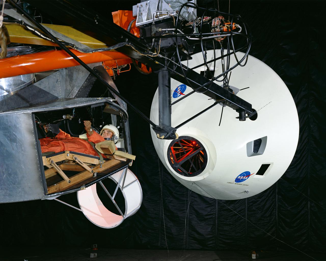
Originally the Rendezvous was used by the astronauts preparing for Gemini missions. The Rendezvous Docking Simulator was then modified and used to develop docking techniques for the Apollo program. This picture shows a later configuration of the Apollo docking with the LEM target. A.W. Vogeley described the simulator as follows: The Rendezvous Docking Simulator and also the Lunar Landing Research Facility are both rather large moving-base simulators. It should be noted, however, that neither was built primarily because of its motion characteristics. The main reason they were built was to provide a realistic visual scene. A secondary reason was that they would provide correct angular motion cues (important in control of vehicle short-period motions) even though the linear acceleration cues would be incorrect. -- Published in A.W. Vogeley, Piloted Space-Flight Simulation at Langley Research Center, Paper presented at the American Society of Mechanical Engineers, 1966 Winter Meeting, New York, NY, November 27 - December 1, 1966.
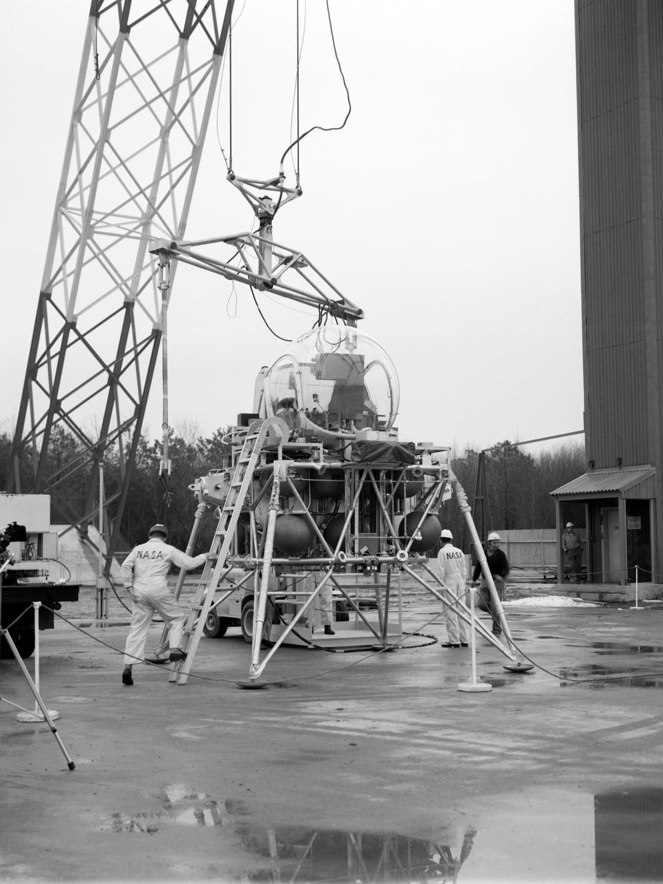
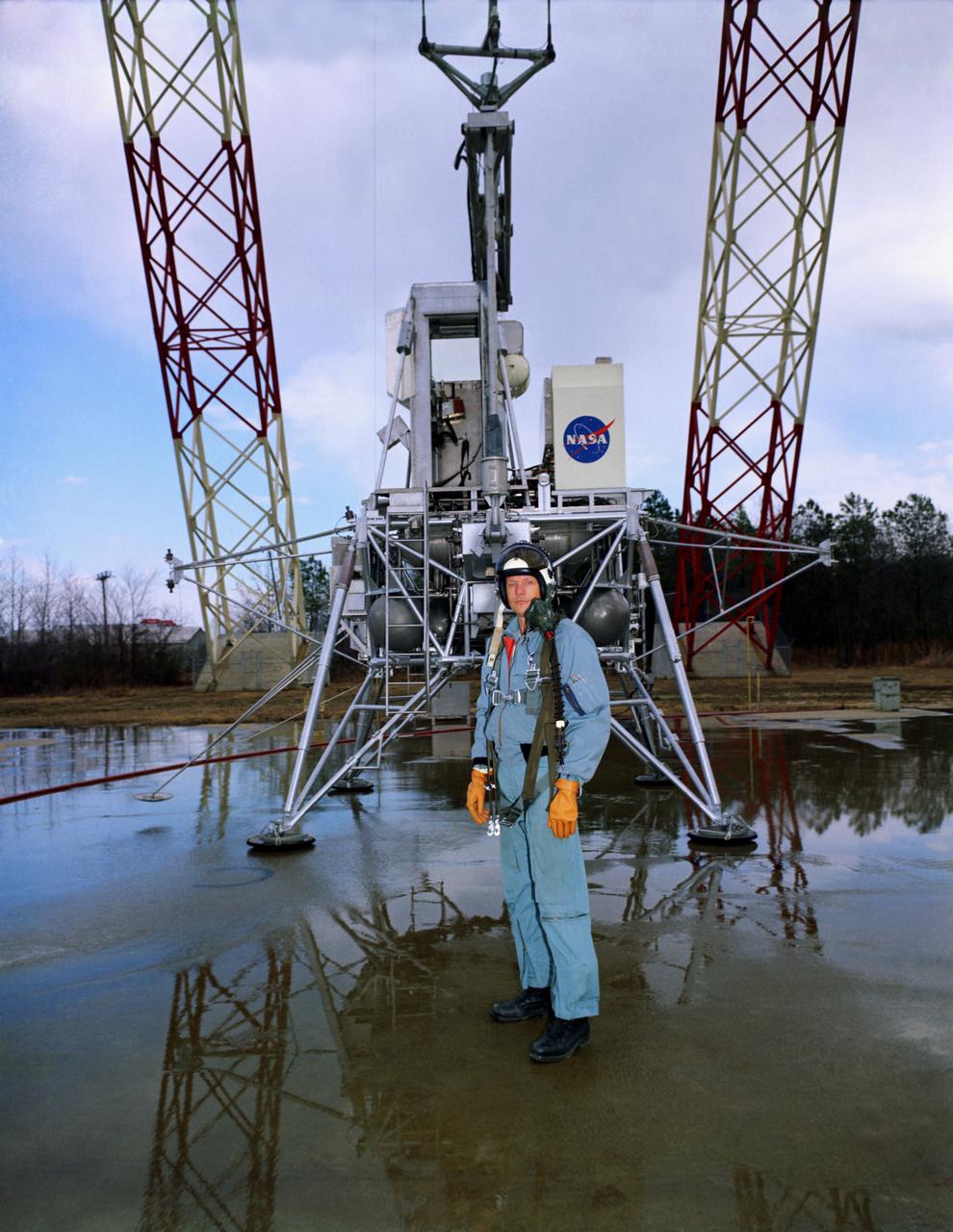
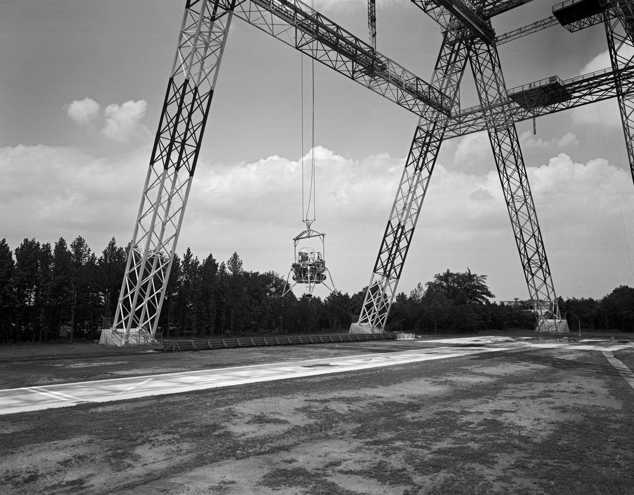
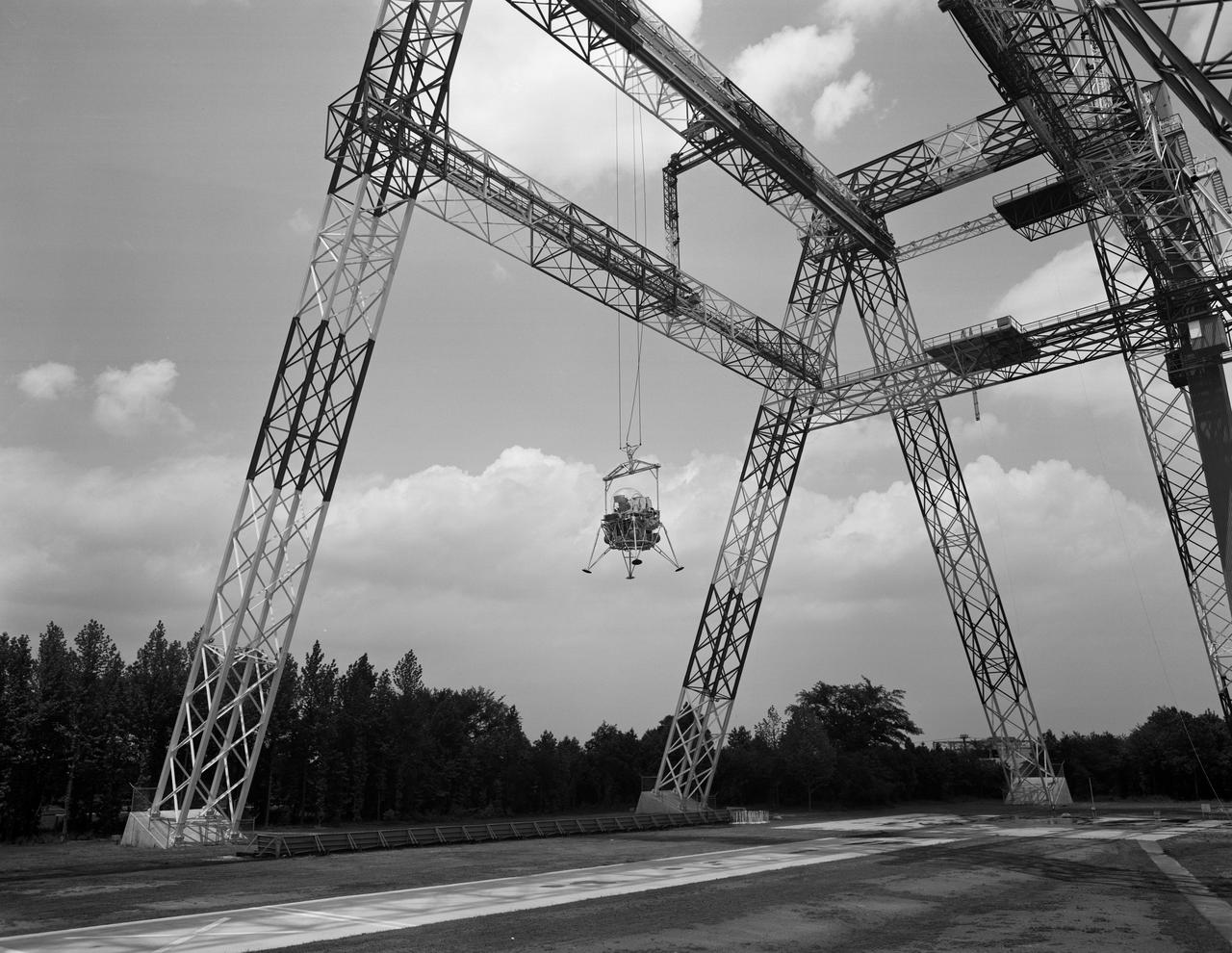
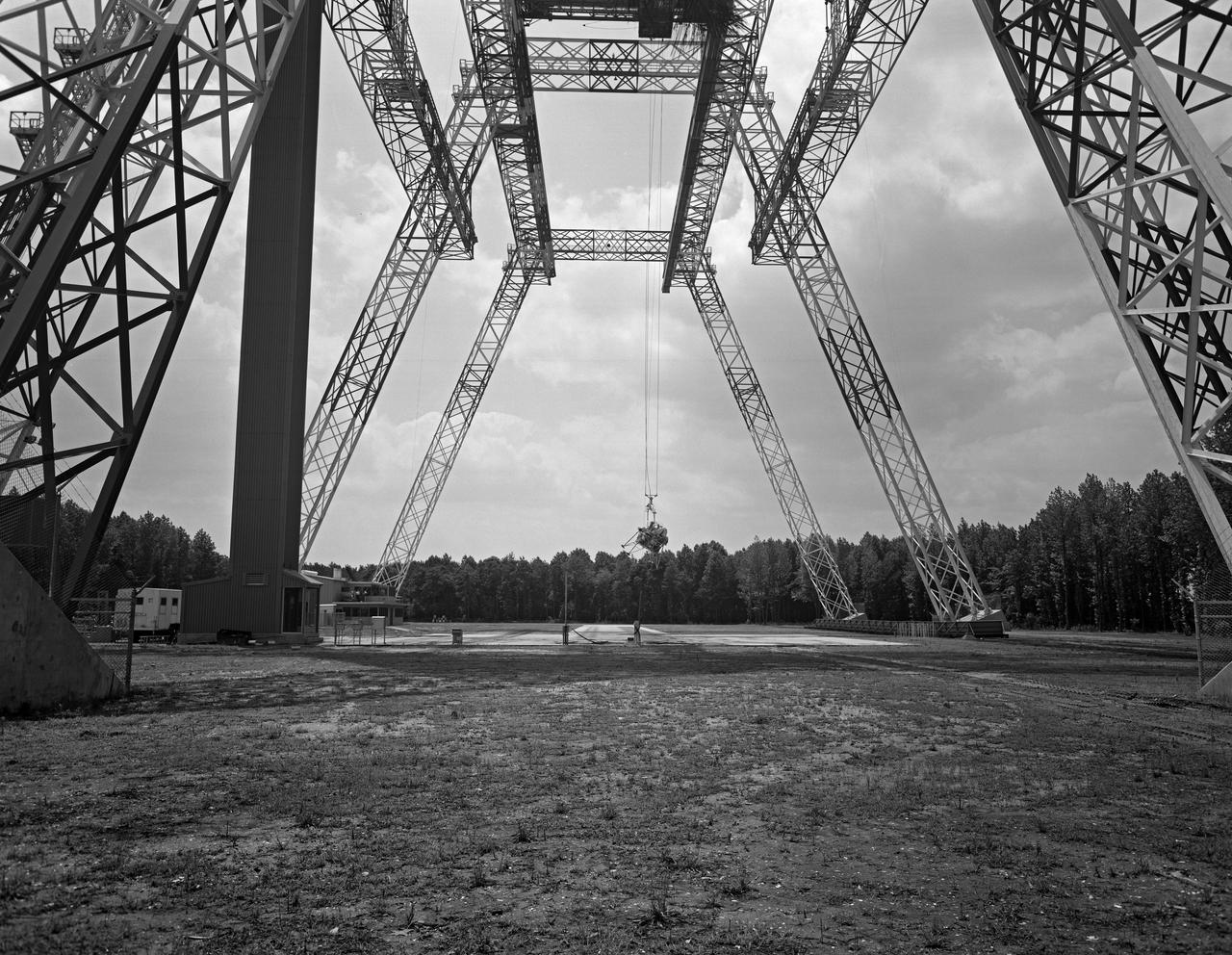
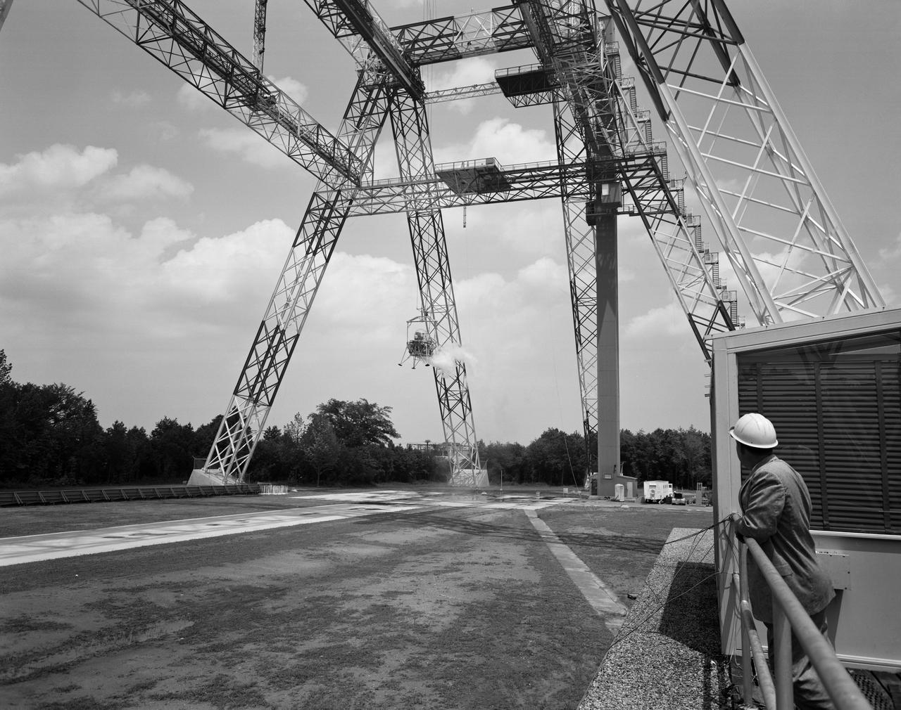
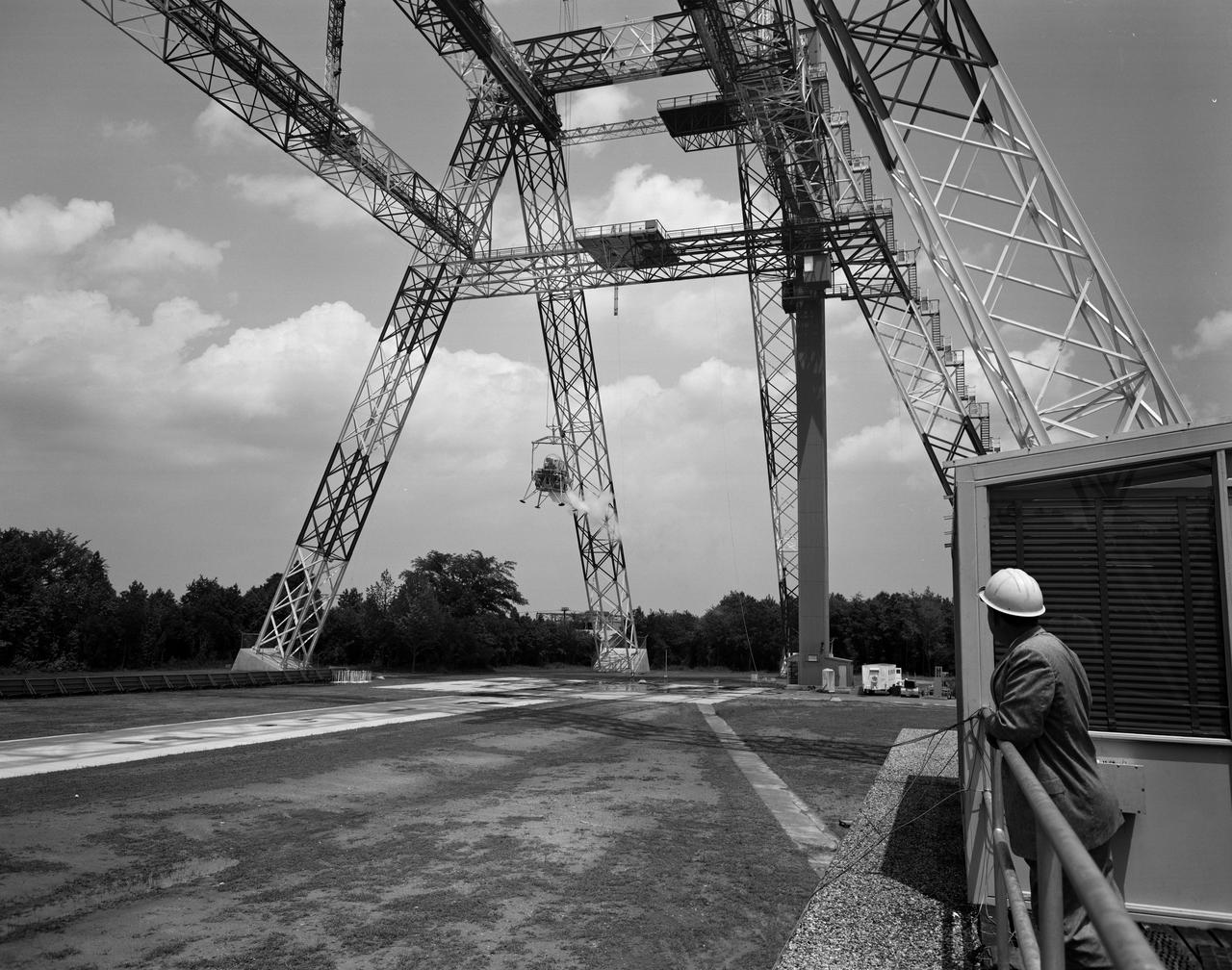
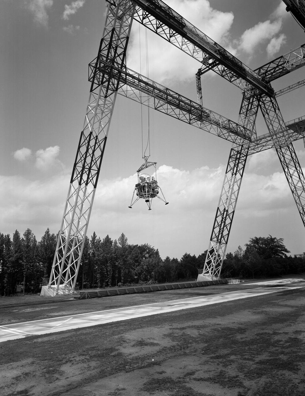
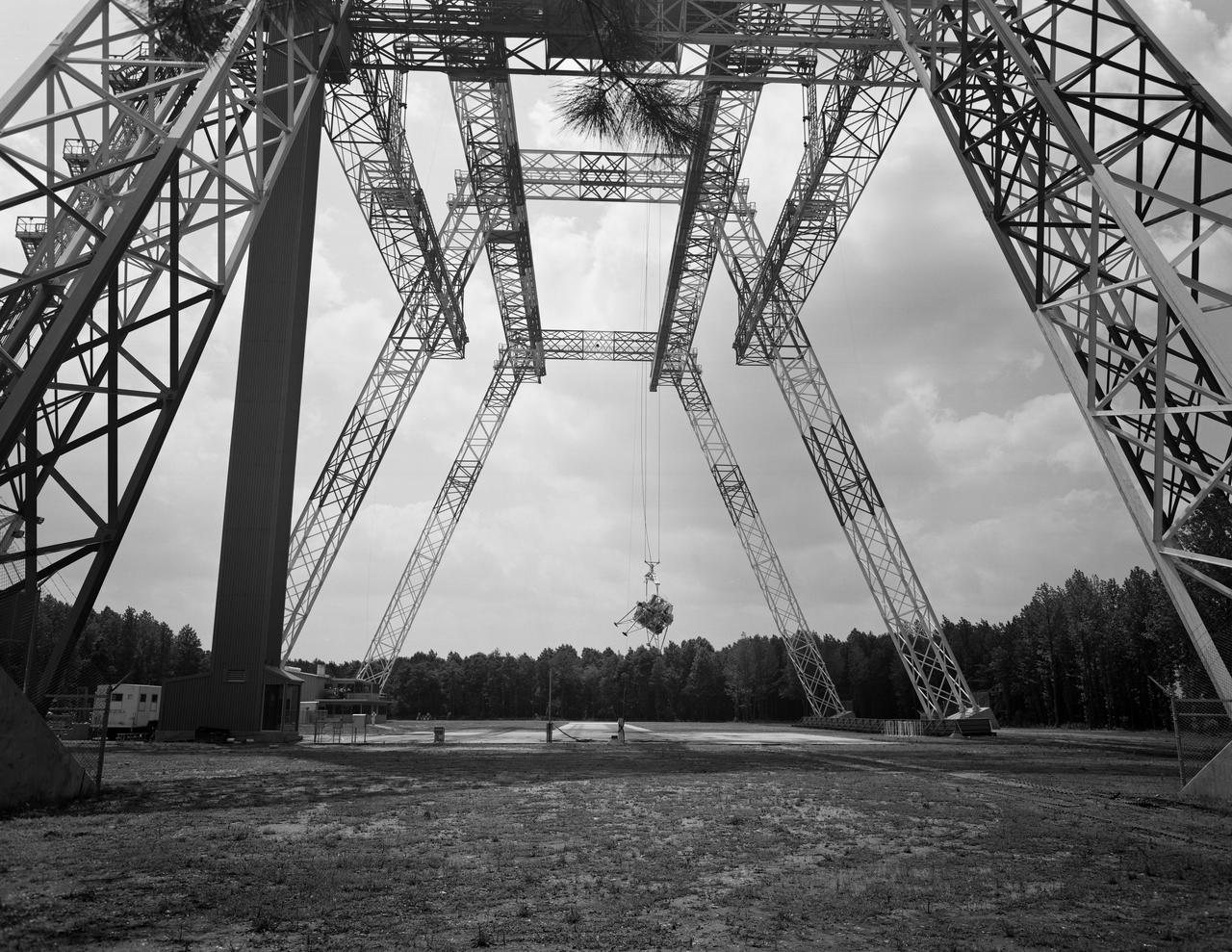
Lunar landing test of LEM at Lunar Landing Research Facility (LLRF).
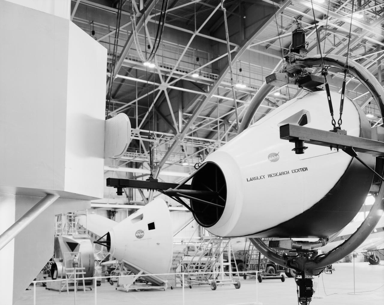
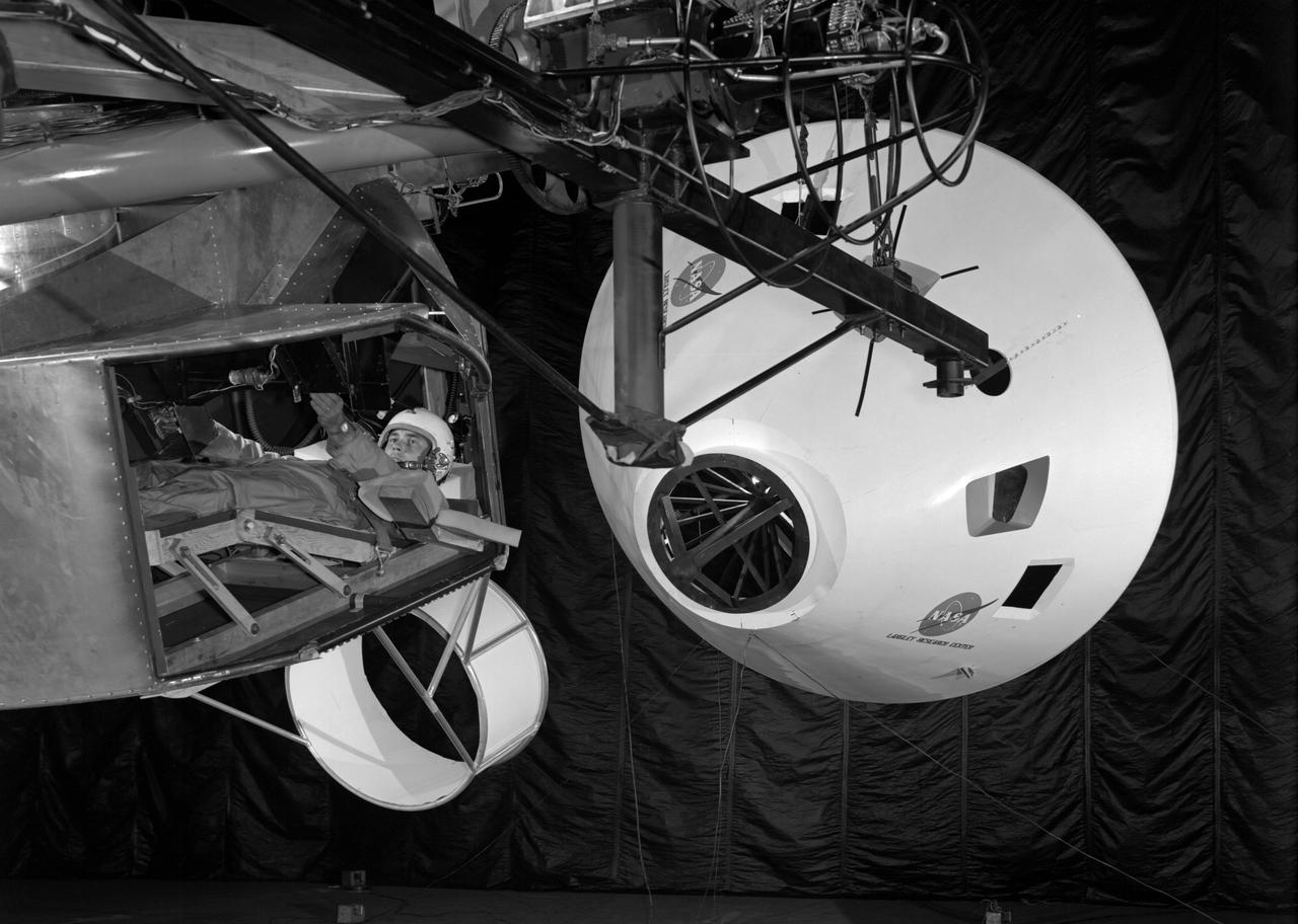
Simulator for Apollo Rendezvous Lunar Excursion Module (LEM)
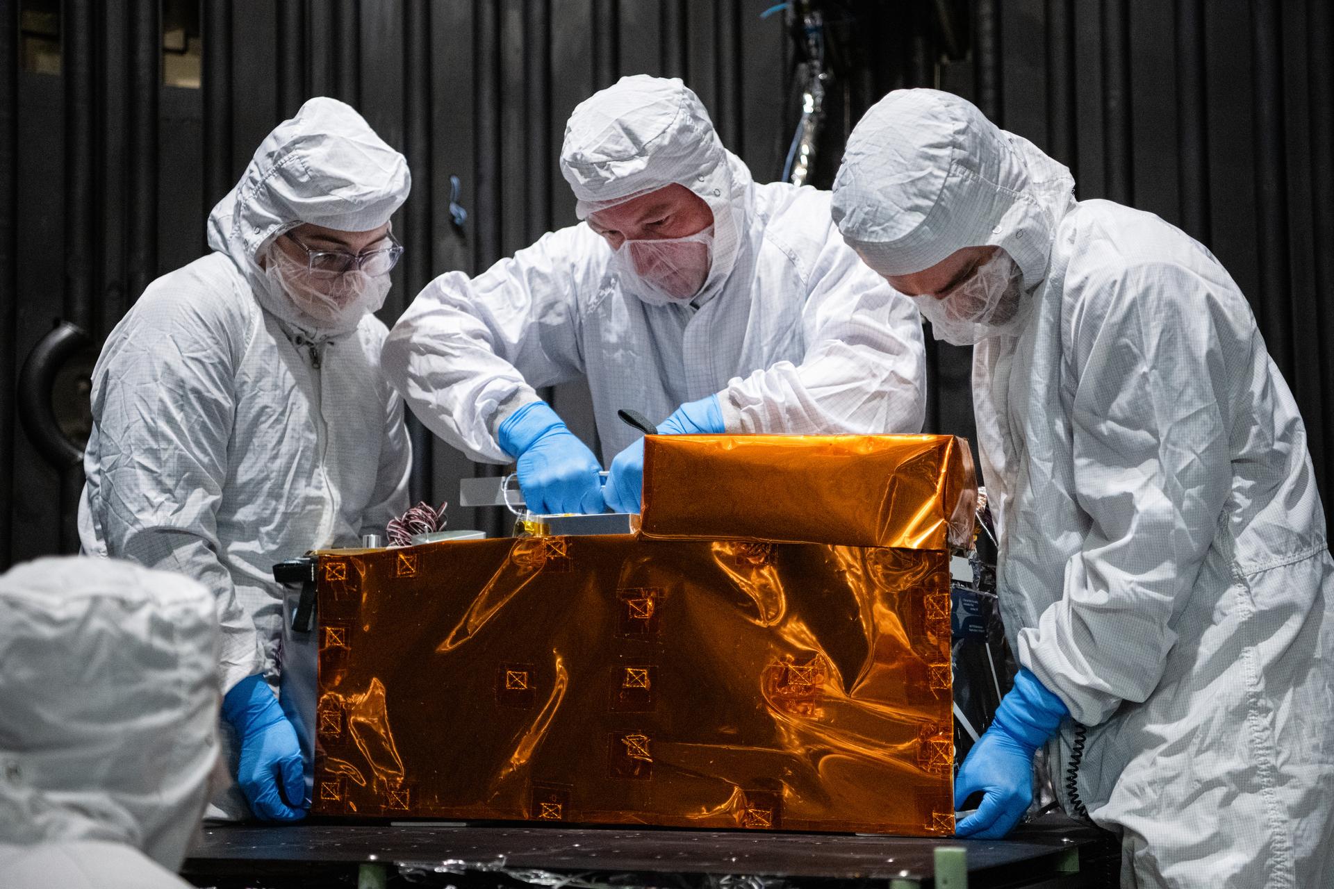
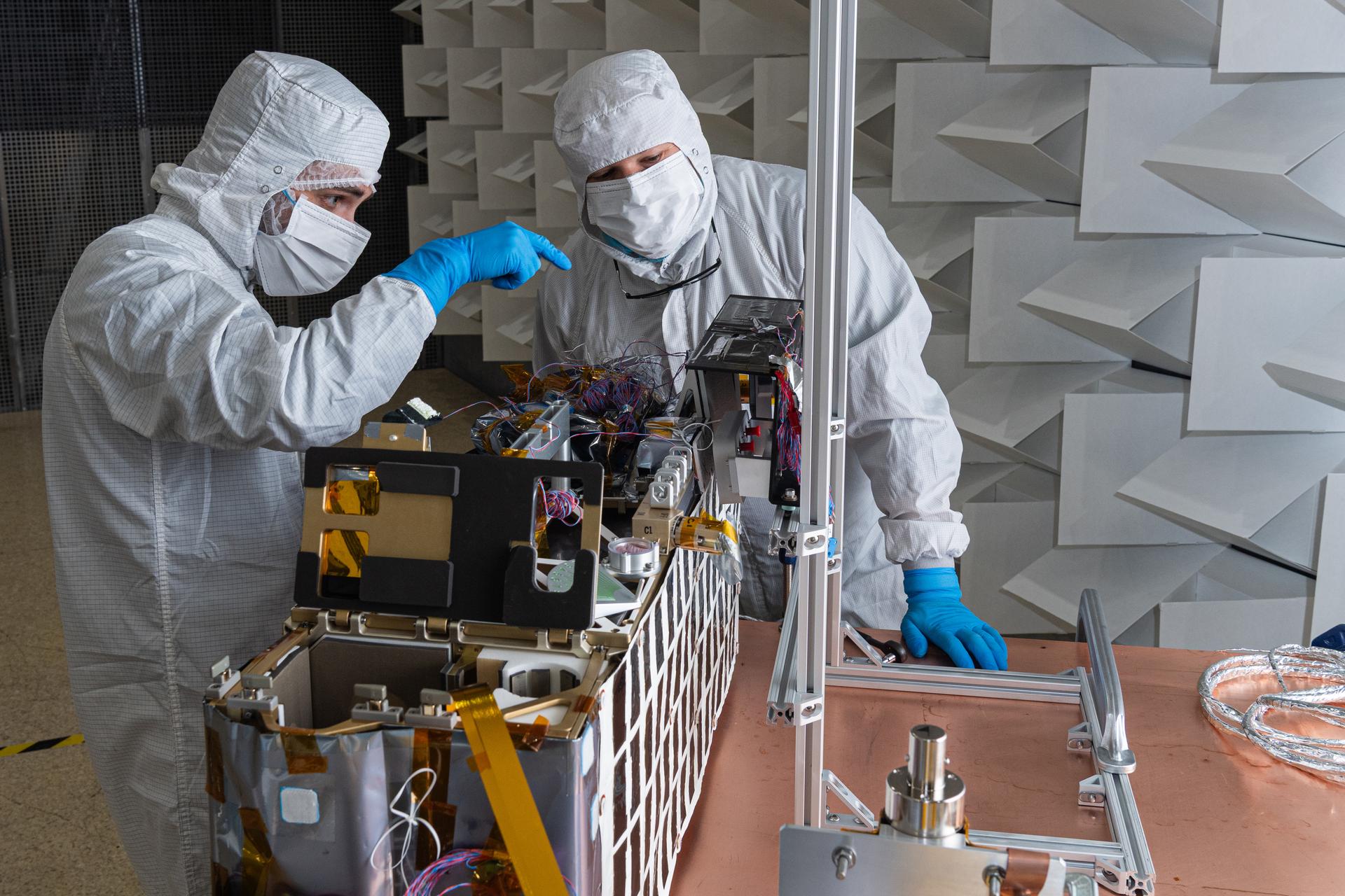
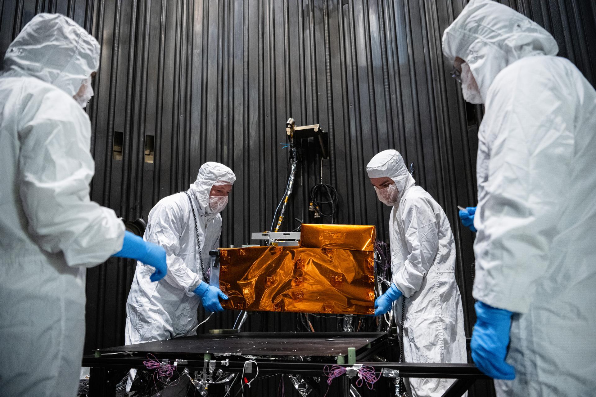
From left, mechanical engineer Gabrielle Ludwig, technician Alex Schaeffer, and mechanical engineer Mitchell Hamann install the Lunar Environment Monitoring Station (LEMS) instrument onto a test plate in a thermal vacuum chamber at Goddard Space Flight Center, Greenbelt Md., March 30, 2026. LEMS is a compact, autonomous, and self-sustaining seismometer suite designed to carry out continuous, long-term, monitoring of the lunar seismic environment at the South Polar region. Photo Credit: NASA/Denny Henry
Engineering technician Jancilon Viegas installs thermocouples onto the The Lunar Environment Monitoring Station (LEMS) instrument in preparation for testing in a thermal vacuum chamber at Goddard Space Flight Center, Greenbelt Md., March 30, 2026. LEMS is a compact, autonomous, and self-sustaining seismometer suite designed to carry out continuous, long-term, monitoring of the lunar seismic environment at the South Polar region. Photo Credit: NASA/Denny Henry
Mitchell Hamann and John Pindell configure the Lunar Environment Monitoring Station (LEMS) instrument for testing in the Electromagnetic Interference/Electromagnetic Compatibility (EMI/EMC) Chamber at Goddard Space Flight Center, Greenbelt Md., Feb 17, 2026. LEMS is a compact, autonomous, and self-sustaining seismometer suite designed to carry out continuous, long-term, monitoring of the lunar seismic environment at the South Polar region. Photo Credit: NASA/Mike Guinto
Lunar Environment Monitoring Station (LEMS) team members install the instrument for testing in the Electromagnetic Interference/Electromagnetic Compatibility (EMI/EMC) Chamber at Goddard Space Flight Center, Greenbelt Md., Feb 13, 2026. LEMS is a compact, autonomous, and self-sustaining seismometer suite designed to carry out continuous, long-term, monitoring of the lunar seismic environment at the South Polar region. Photo Credit: NASA/Denny Henry
Chief Operating Officer of Quest Thermal Group Phillip Tyler installs Integrated Multilayer Insulation (IMLI) on the Lunar Environment Monitoring Station for Artemis (LEMS) bus inside a cleanroom at Goddard Space Flight Center, Greenbelt Md., Jan 13, 2026. LEMS is a compact, autonomous, and self-sustaining seismometer suite designed to carry out continuous, long-term, monitoring of the lunar seismic environment at the South Polar region. Photo Credit: NASA/Denny Henry
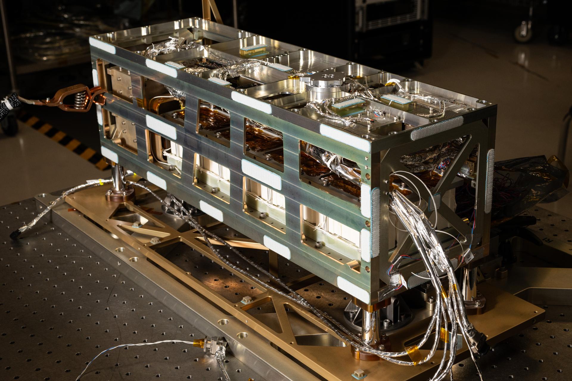
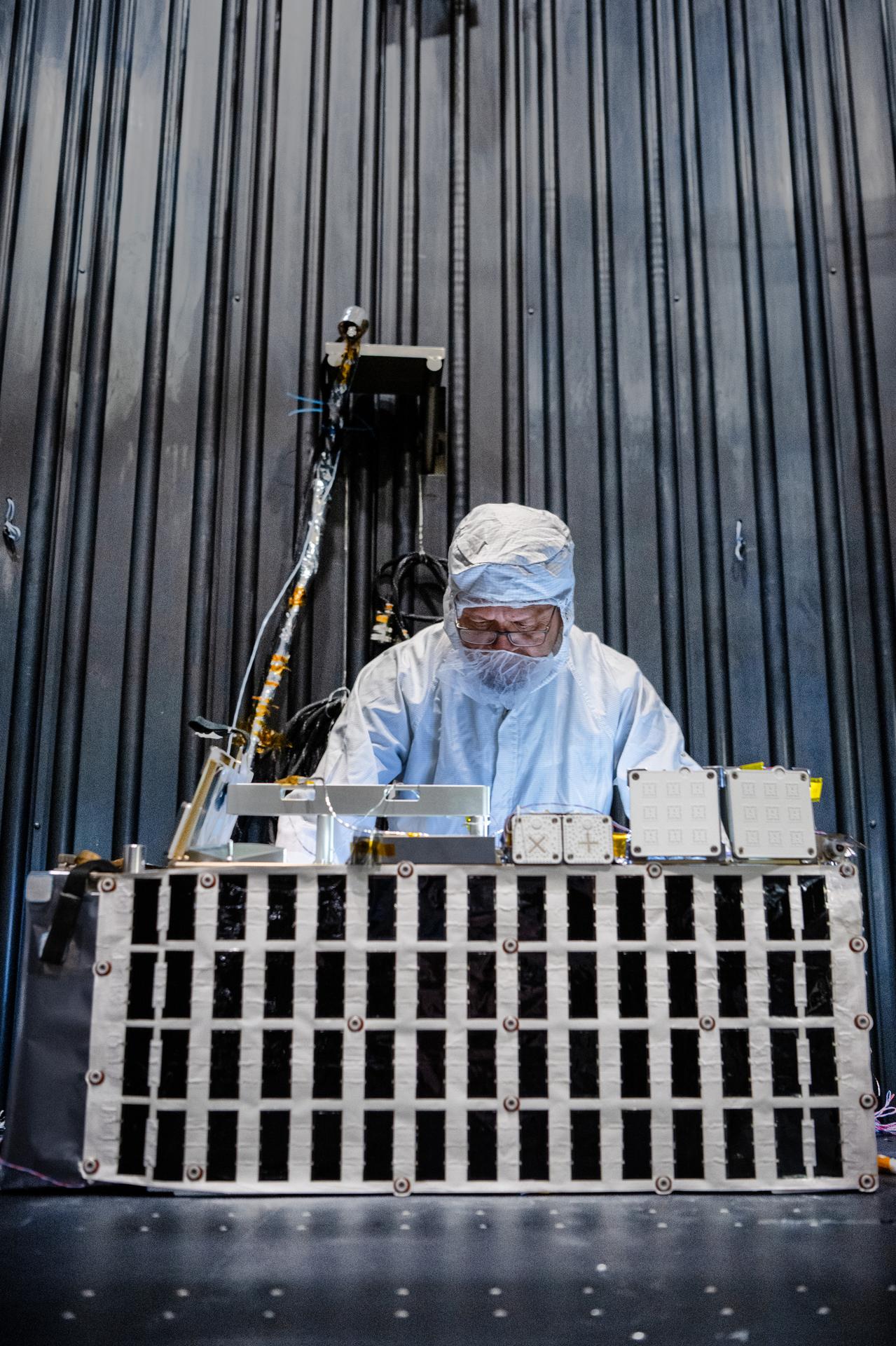
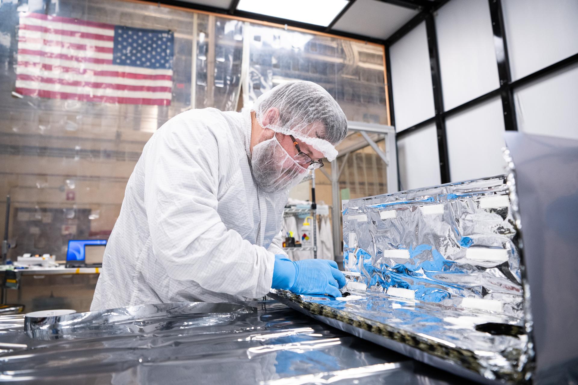
A detail view of the Lunar Environment Monitoring Station, (LEMS) bus prior to thermal blanket installation inside the cleanroom at Goddard Space Flight Center, Greenbelt Md., Jan 12, 2026. LEMS is a compact, autonomous, and self-sustaining seismometer suite designed to carry out continuous, long-term, monitoring of the lunar seismic environment at the South Polar region. Photo Credit: NASA/Denny Henry
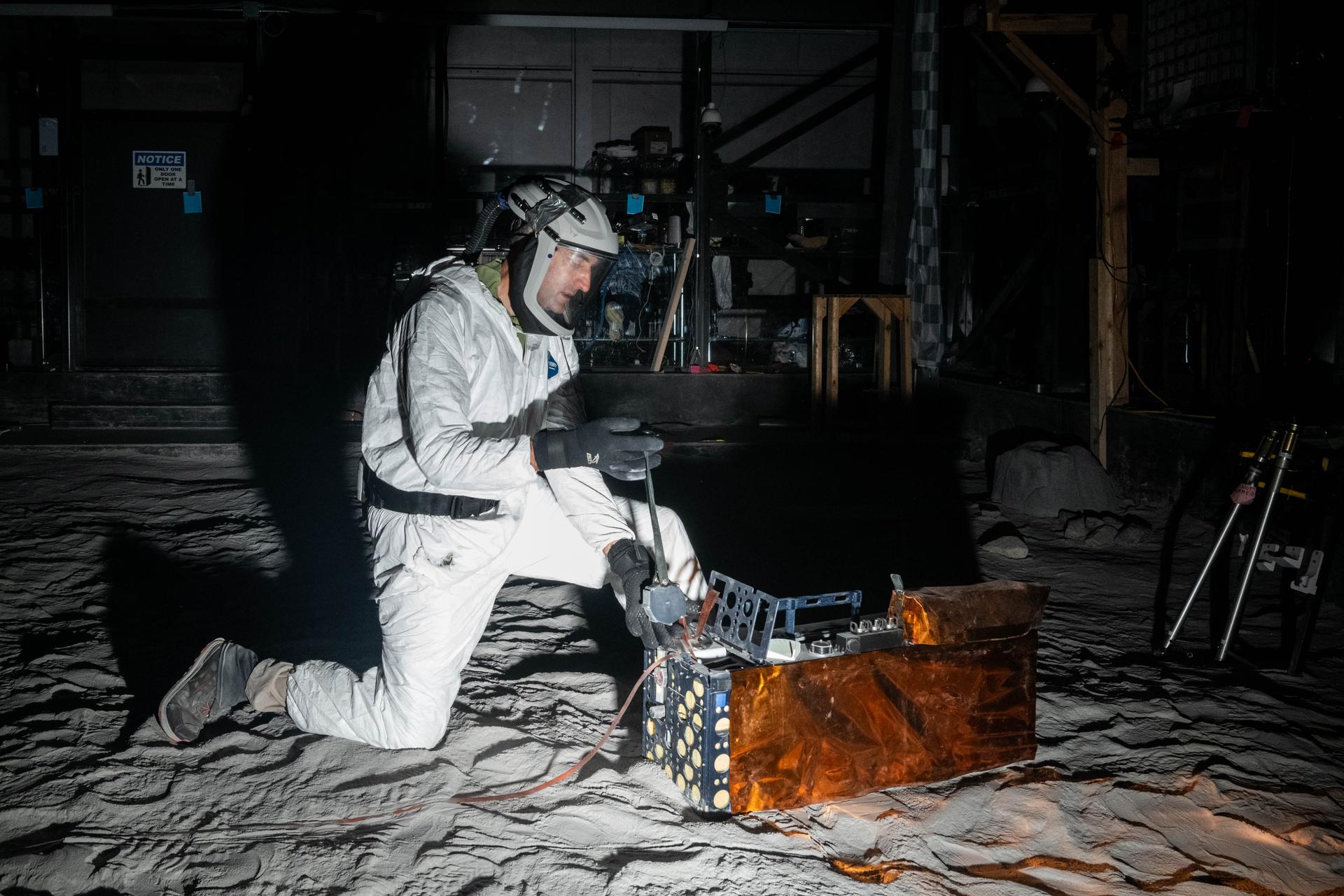
Artemis Scientist, Trevor Graff, performs instrument deployment exercises with a medium fidelity mock up of the Lunar Environment Monitoring Station (LEMS) in the lunar simulant bin at the Florida Space Institute Exolith Lab, Orlando, Fl., Aug 6, 2025. LEMS is a compact, autonomous, and self-sustaining seismometer suite designed to carry out continuous, long-term, monitoring of the lunar seismic environment at the South Polar region. Photo Credit: NASA/Katie Mellos.
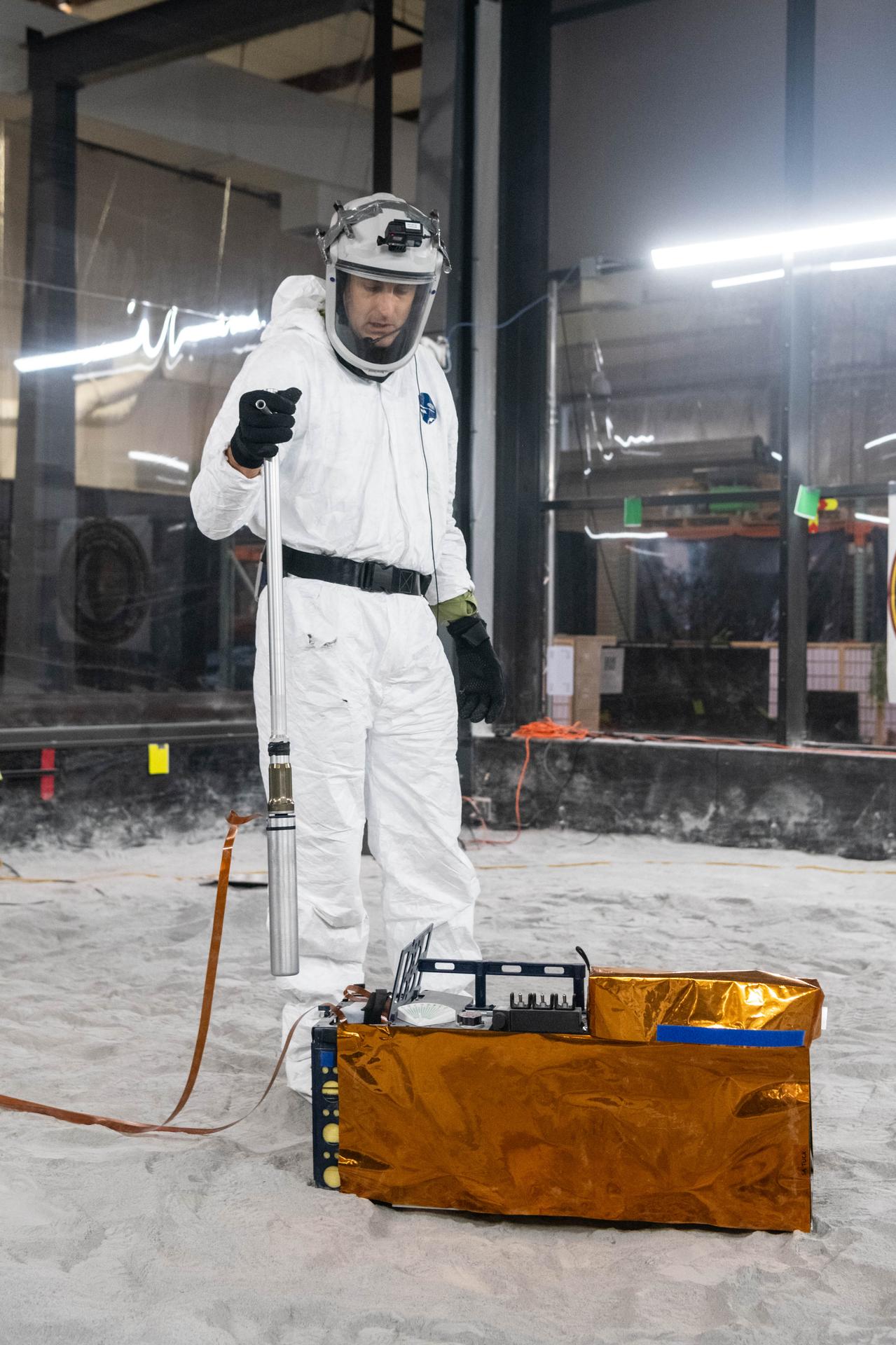
Artemis Scientist, Trevor Graff, performs instrument deployment exercises with a medium fidelity mock up of the Lunar Environment Monitoring Station (LEMS) in the lunar simulant bin at the Florida Space Institute Exolith Lab, Orlando, Fl., Aug 6, 2025. LEMS is a compact, autonomous, and self-sustaining seismometer suite designed to carry out continuous, long-term, monitoring of the lunar seismic environment at the South Polar region. Photo Credit: NASA/Katie Mellos.
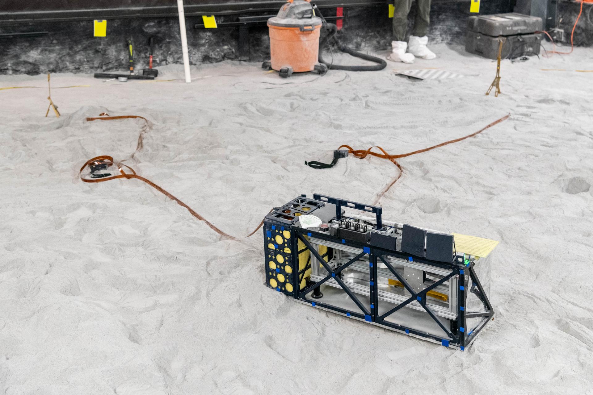
The Lunar Environment Monitoring Station (LEMS) medium fidelity instrument mock up is configured for instrument deployment exercises in the lunar simulant bin at the Florida Space Institute Exolith Lab, Orlando, Fl., Aug 6, 2025. LEMS is a compact, autonomous, and self-sustaining seismometer suite designed to carry out continuous, long-term, monitoring of the lunar seismic environment at the South Polar region. Photo Credit: NASA/Katie Mellos.
Team members install the Lunar Environment Monitoring Station (LEMS) instrument for testing in a thermal vacuum chamber at Goddard Space Flight Center, Greenbelt Md., March 30, 2026. LEMS is a compact, autonomous, and self-sustaining seismometer suite designed to carry out continuous, long-term, monitoring of the lunar seismic environment at the South Polar region. Photo Credit: NASA/Denny Henry
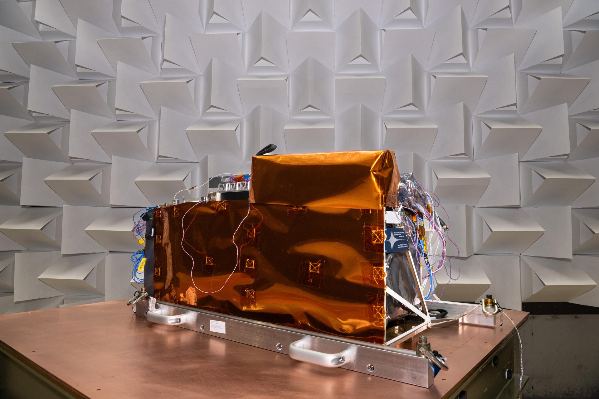
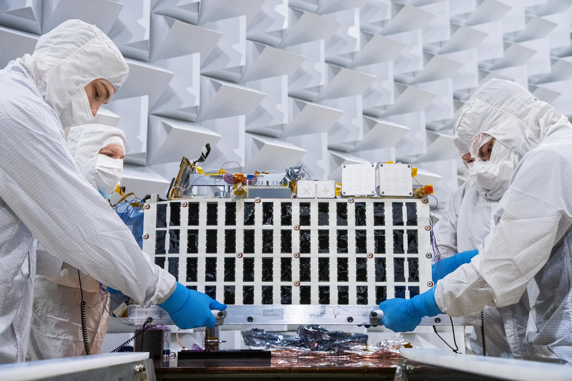
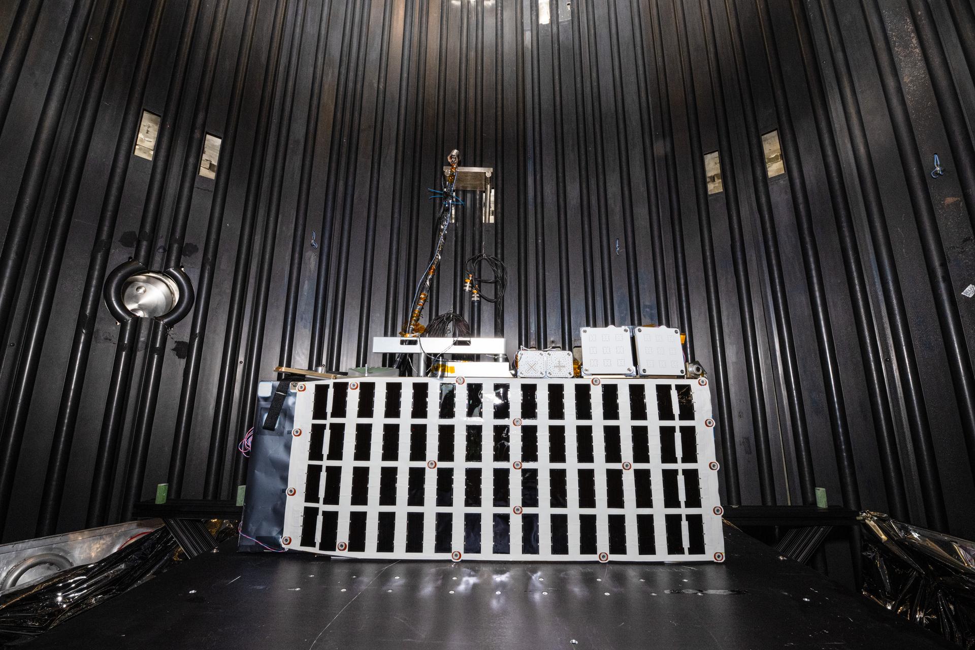
The Lunar Environment Monitoring Station (LEMS) in Electromagnetic Interference/Electromagnetic Compatibility (EMI/EMC) Chamber at Goddard Space Flight Center, Greenbelt Md., Feb 11, 2026. LEMS is a compact, autonomous, and self-sustaining seismometer suite designed to carry out continuous, long-term, monitoring of the lunar seismic environment at the South Polar region. Photo Credit: NASA/Denny Henry
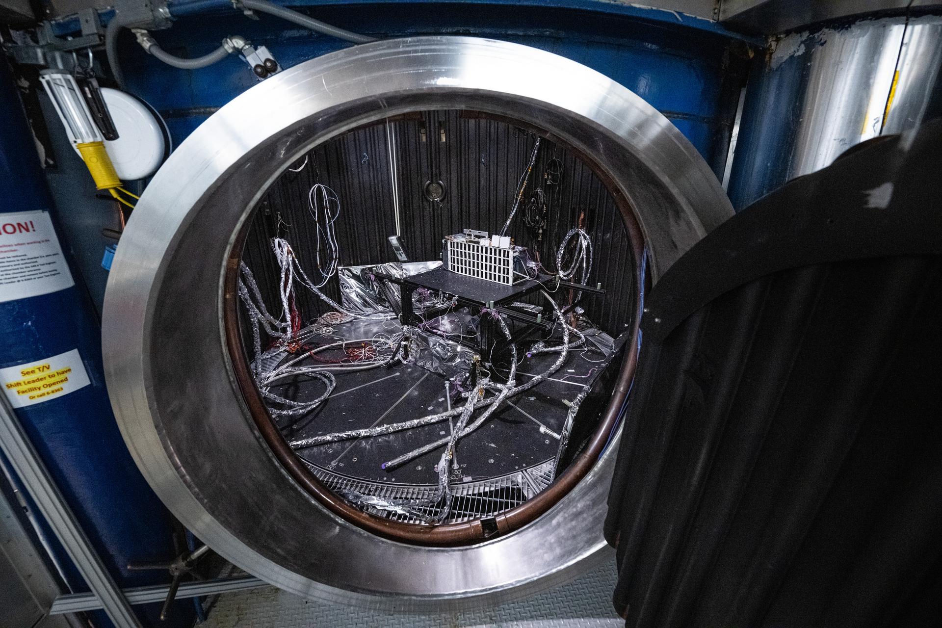
The Lunar Environment Monitoring Station (LEMS) instrument is installed for testing in a thermal vacuum chamber at Goddard Space Flight Center, Greenbelt Md., March 30, 2026. LEMS is a compact, autonomous, and self-sustaining seismometer suite designed to carry out continuous, long-term, monitoring of the lunar seismic environment at the South Polar region. Photo Credit: NASA/Denny Henry
The Lunar Environment Monitoring Station (LEMS) instrument is installed for testing in a thermal vacuum chamber at Goddard Space Flight Center, Greenbelt Md., March 30, 2026. LEMS is a compact, autonomous, and self-sustaining seismometer suite designed to carry out continuous, long-term, monitoring of the lunar seismic environment at the South Polar region. Photo Credit: NASA/Denny Henry
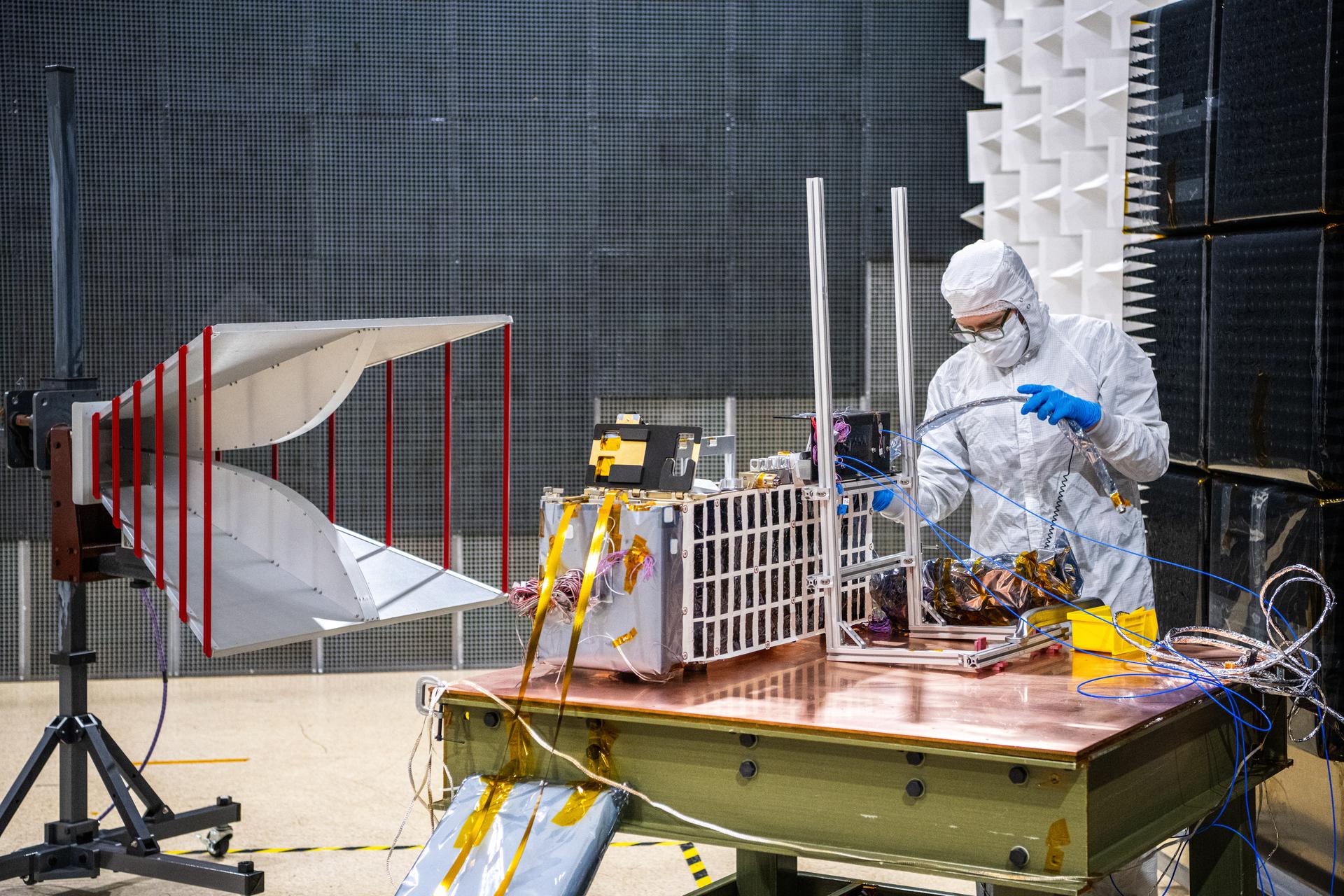
Electrical test engineer Thomas Schluszas configures the Lunar Environment Monitoring Station (LEMS) instrument for testing in the Electromagnetic Interference/Electromagnetic Compatibility (EMI/EMC) Chamber at Goddard Space Flight Center, Greenbelt Md., Feb 17, 2026. LEMS is a compact, autonomous, and self-sustaining seismometer suite designed to carry out continuous, long-term, monitoring of the lunar seismic environment at the South Polar region. Photo Credit: NASA/Denny Henry
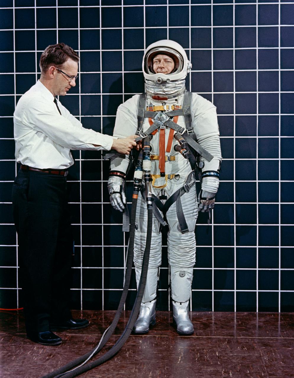
Engineer Bill Peterson fits test pilot Bob Smyth in spacesuit A-3H-024 with the LEM Astronaut restraint harness during suit evaluation study.
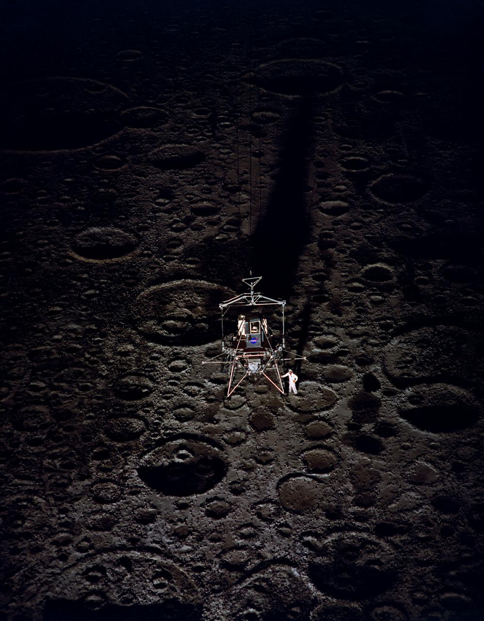
During a nighttime training session, a multiple exposure captures the movement of the Lunar Excursion Module Simulator (LEMS). The LEMS was a manned vehicle used to familiarize the Apollo astronauts with the handling characteristics of lunar-landing type vehicle. The Apollo Program is best known for the astronaut Neal Armstrong s first step on the Moon July 20, 1969. In its earliest test period, the LEMS featured a helicopter crew cabin atop the lunar landing module. Later, the helicopter crew cabin was replaced with a stand-up rectangular cabin which was more efficient for controlling maneuvers and for better viewing by the pilot. The vehicle was designed at Langley Research Center in Hampton, VA. This multiple exposure shows a simulated Moon landing of the (LEMS) trainer at Langley s Lunar Landing Research Facility. -- Photograph published in Winds of Change, 75th Anniversary NASA publication (page 70), by James Shultz. Also published in " A Century at Langley" by Joseph Chambers, pg. 93.
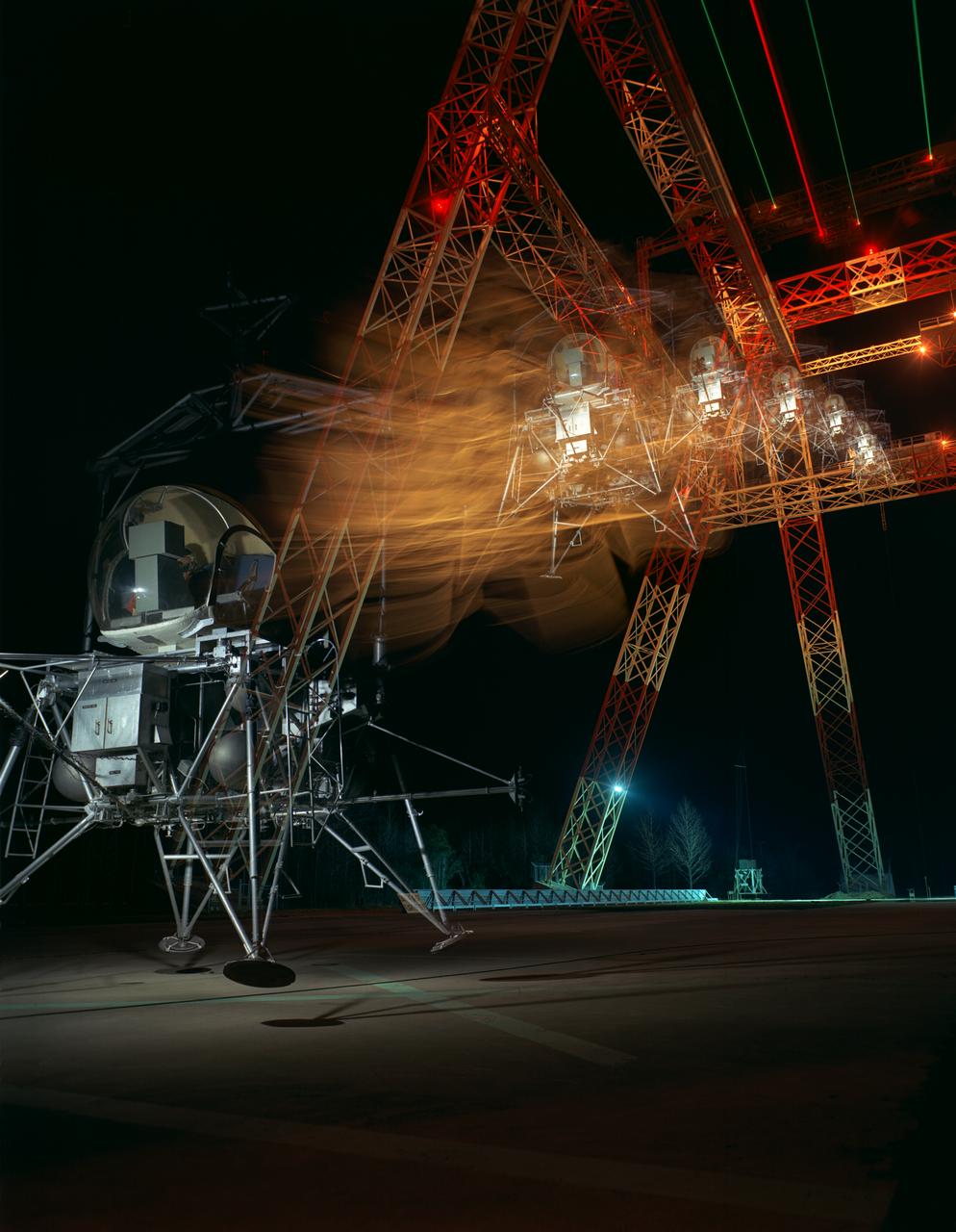
During a nighttime training session, a multiple exposure captures the movement of the Lunar Excursion Module Simulator (LEMS). The LEMS was a manned vehicle used to familiarize the Apollo astronauts with the handling characteristics of lunar-landing type vehicle. The Apollo Program is best known for the astronaut Neal Armstrong s first step on the Moon July 20, 1969. In its earliest test period, the LEMS featured a helicopter crew cabin atop the lunar landing module. Later, the helicopter crew cabin was replaced with a stand-up rectangular cabin which was more efficient for controlling maneuvers and for better viewing by the pilot. The vehicle was designed at Langley Research Center in Hampton, VA. This multiple exposure shows a simulated Moon landing of the (LEMS) trainer at Langley s Lunar Landing Research Facility. -- Photograph published in Winds of Change, 75th Anniversary NASA publication (page 70), by James Shultz. Also published in " A Century at Langley" by Joseph Chambers, pg. 93.
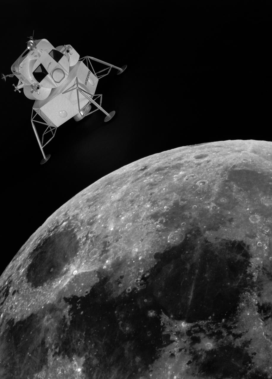
Artist rendering of the lunar excursion module approaching the moon. The lunar module design underwent gradual evolution from the first configuration proposed by Grumman in 1962. This model is a 1964 rendering. Langley had the task of building a simulator for the astronauts to practice lunar landings. The configuration of the initial vehicle used with the Lunar Landing Research Facility (LLRF) was changed in 1967 to more accurately reflect the standing position of the astronauts, cockpit arrangement, instrumentation, controls and field of view.
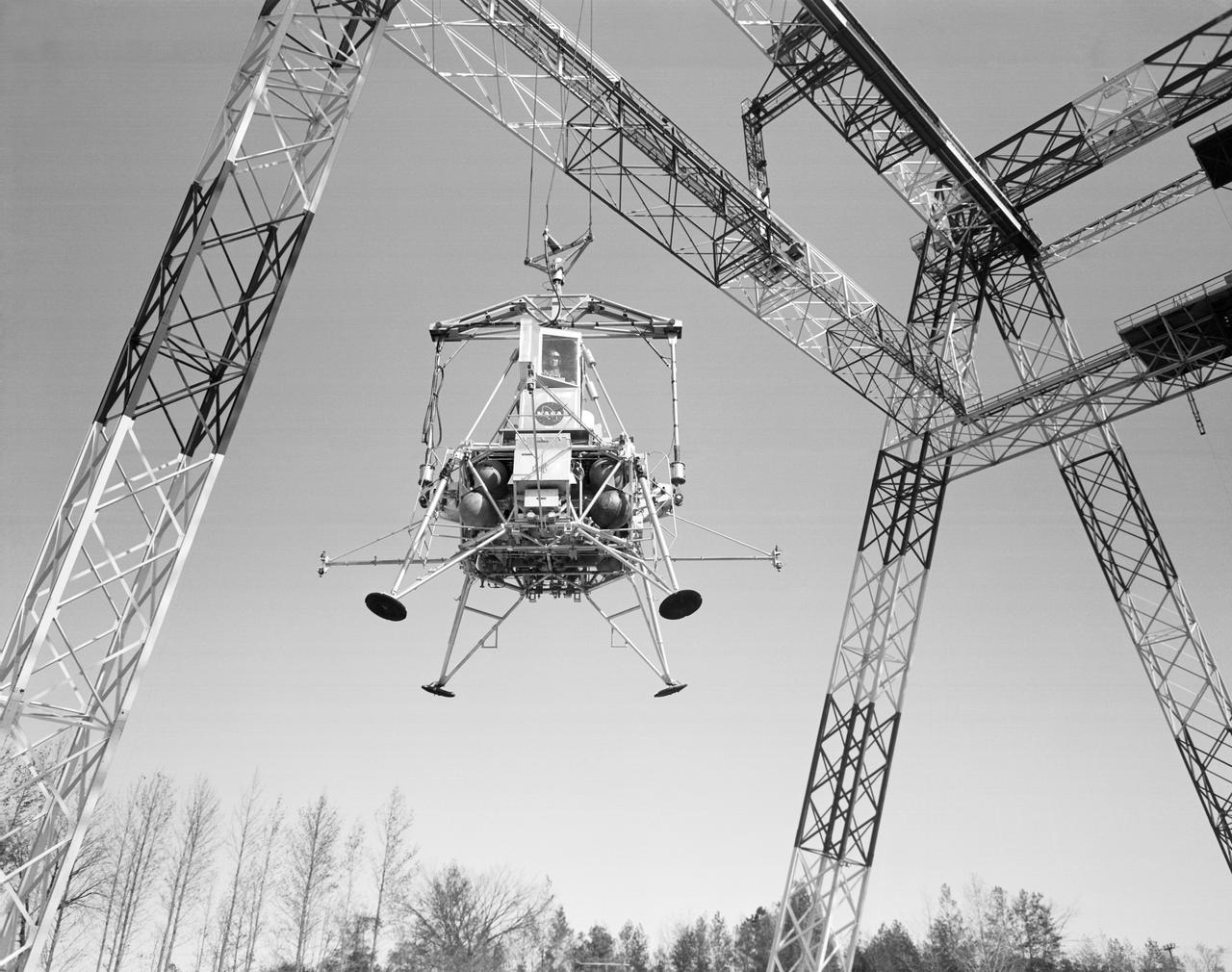
Lunar landing test of LEM at LLRF Lunar Landing Research Facility: A NASA Langley research pilot flies a lunar lander in a test conducted in the Lunar Landing Research Facility.
Simulator for Apollo Rendezvous Lunar Excursion Module (LEM)
A detail view of the Lunar Environment Monitoring Station, (LEMS) inside the cleanroom at Goddard Space Flight Center, Greenbelt Md., Jan 30, 2026. The Lunar Environment Monitoring Station for Artemis (LEMS) is a compact, autonomous, and self-sustaining seismometer suite designed to carry out continuous, long-term, monitoring of the lunar seismic environment at the South Polar region. Photo Credit: NASA/Mike Guinto
Neil Armstrong with the Lunar Excursion Module (LEM). Caption: "Not long after this photo was taken in front of the Lunar Landing Research Facility, astronaut Neil Armstrong became the first human to step upon the surface of the Moon." Photograph published in Winds of Change, 75th Anniversary NASA publication, by James Schultz, page 91. Also published in " A Century at Langley" by Joseph Chambers, pg. 95
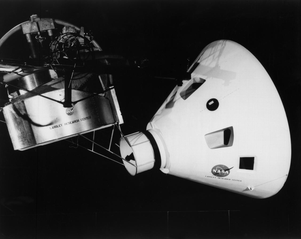
Originally the Rendezvous was used by the astronauts preparing for Gemini missions. The Rendezvous Docking Simulator was then modified and used to develop docking techniques for the Apollo program. "The LEM pilot's compartment, with overhead window and the docking ring (idealized since the pilot cannot see it during the maneuvers), is shown docked with the full-scale Apollo Command Module." A.W. Vogeley described the simulator as follows: "The Rendezvous Docking Simulator and also the Lunar Landing Research Facility are both rather large moving-base simulators. It should be noted, however, that neither was built primarily because of its motion characteristics. The main reason they were built was to provide a realistic visual scene. A secondary reason was that they would provide correct angular motion cues (important in control of vehicle short-period motions) even though the linear acceleration cues would be incorrect." -- Published in A.W. Vogeley, "Piloted Space-Flight Simulation at Langley Research Center," Paper presented at the American Society of Mechanical Engineers, 1966 Winter Meeting, New York, NY, November 27 - December 1, 1966;
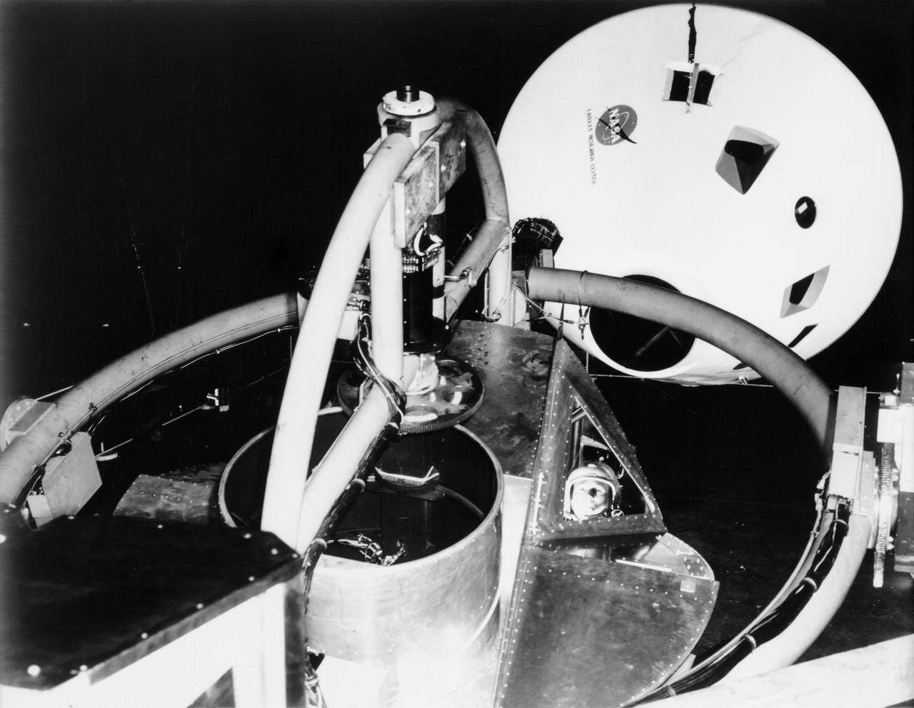
Originally the Rendezvous was used by the astronauts preparing for Gemini missions. The Rendezvous Docking Simulator was then modified and used to develop docking techniques for the Apollo program. "The LEM pilot's compartment, with overhead window and the docking ring (idealized since the pilot cannot see it during the maneuvers), is shown docked with the full-scale Apollo Command Module." A.W. Vogeley described the simulator as follows: "The Rendezvous Docking Simulator and also the Lunar Landing Research Facility are both rather large moving-base simulators. It should be noted, however, that neither was built primarily because of its motion characteristics. The main reason they were built was to provide a realistic visual scene. A secondary reason was that they would provide correct angular motion cues (important in control of vehicle short-period motions) even though the linear acceleration cues would be incorrect." -- Published in A.W. Vogeley, "Piloted Space-Flight Simulation at Langley Research Center," Paper presented at the American Society of Mechanical Engineers, 1966 Winter Meeting, New York, NY, November 27 - December 1, 1966;
ASTRONAUT TRAINING APOLLO - LEM APOLLO MISSION SIMULATOR; NEUTRAL BOUYANCY FACILITY TANK; DYNAMIC CREW SIMULATOR; LUNAR MODULE SIMULATOR; CM PROCEDURES SIMULATOR; ANECHOIC CHAMBER;
Originally the Rendezvous was used by the astronauts preparing for Gemini missions. The Rendezvous Docking Simulator was then modified and used to develop docking techniques for the Apollo program. The pilot is shown maneuvering the LEM into position for docking with a full-scale Apollo Command Module. From A.W. Vogeley, Piloted Space-Flight Simulation at Langley Research Center, Paper presented at the American Society of Mechanical Engineers, 1966 Winter Meeting, New York, NY, November 27 - December 1, 1966. The Rendezvous Docking Simulator and also the Lunar Landing Research Facility are both rather large moving-base simulators. It should be noted, however, that neither was built primarily because of its motion characteristics. The main reason they were built was to provide a realistic visual scene. A secondary reason was that they would provide correct angular motion cues (important in control of vehicle short-period motions) even though the linear acceleration cues would be incorrect. Apollo Rendezvous Docking Simulator: Langley s Rendezvous Docking Simulator was developed by NASA scientists to study the complex task of docking the Lunar Excursion Module with the Command Module in Lunar orbit.
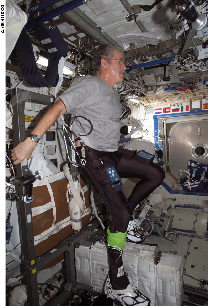
ISS011-E-09822 (29 June 2005) --- Astronaut John L. Phillips, Expedition 11 NASA Space Station science officer and flight engineer, uses the Cycle Ergometer with Vibration Isolation System (CEVIS) while participating in the Foot/Ground Reaction Forces During Spaceflight (FOOT) experiment in the Destiny laboratory of the International Space Station. Phillips wore the specially instrumented Lower Extremity Monitoring Suit (LEMS), cycling tights outfitted with sensors, during the experiment.
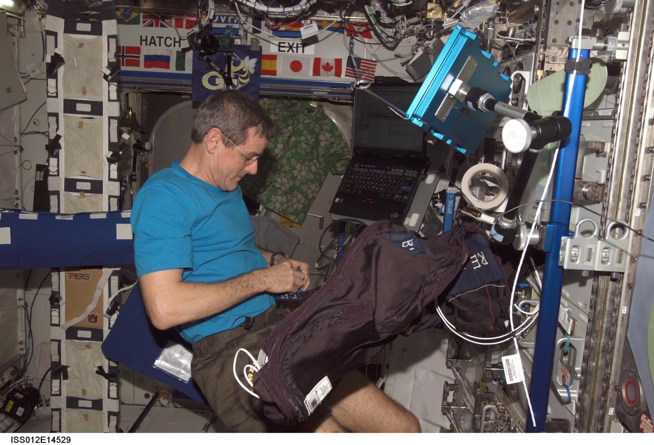
ISS012-E-14529 (10 Jan. 2006) --- Astronaut William S. (Bill) McArthur, Expedition 12 commander and NASA space station science officer, performs Foot/Ground Reaction Forces During Spaceflight (FOOT) experiment set-up operations in the Destiny laboratory of the International Space Station. Foot Ground Interface Flight Calibration Unit (FGI-FCU) is visible upper right and the Lower Extremity Monitoring Suit (LEMS) is visible in the foreground.
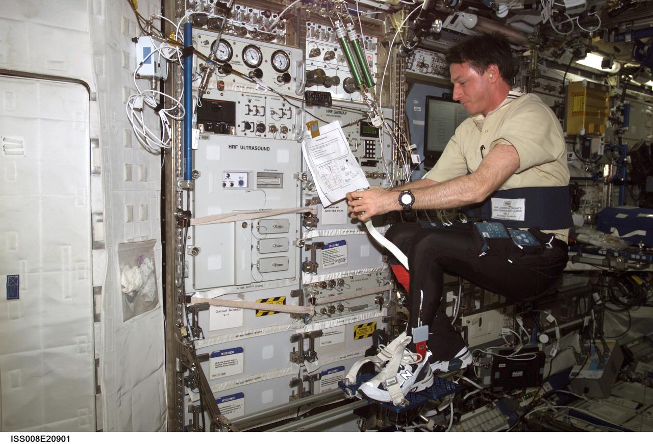
ISS008-E-20901 (7 April 2004) --- Astronaut C. Michael Foale, Expedition 8 commander and NASA ISS science officer, balances on the footplate of a special track attached to the Human Research Facility (HRF) rack in the Destiny laboratory on the International Space Station (ISS) to perform Foot/Ground Reaction Forces During Spaceflight (FOOT) / Electromyography (EMG) calibration operations. Foale is wearing the Lower Extremity Monitoring Suit (LEMS), the cycling tights outfitted with 20 sensors, which measures forces on joints and muscle activity.
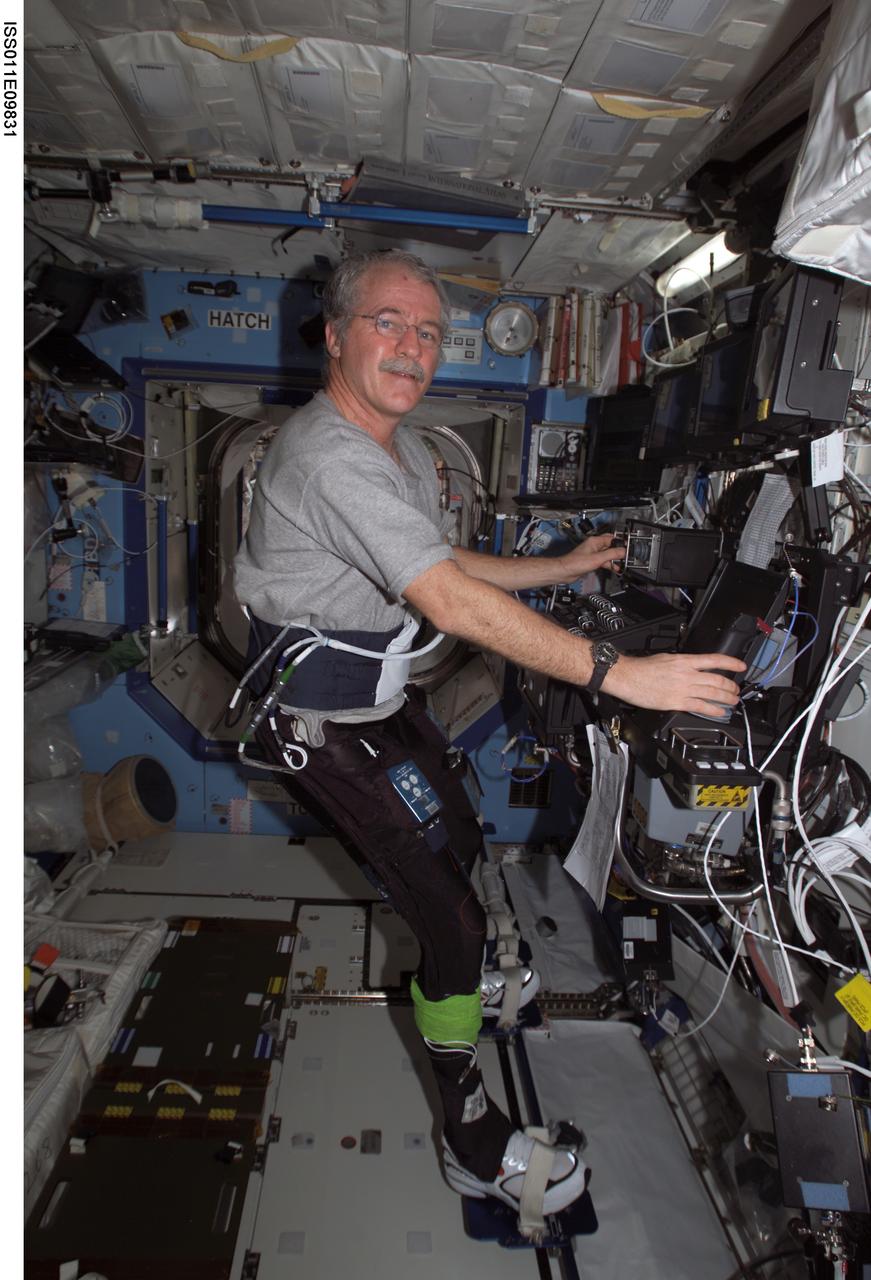
ISS011-E-09831 (29 June 2005) --- Astronaut John L. Phillips, Expedition 11 NASA Space Station science officer and flight engineer, works at the Canadarm2 controls while participating in the Foot/Ground Reaction Forces During Spaceflight (FOOT) experiment in the Destiny laboratory of the International Space Station. Phillips wore the specially instrumented Lower Extremity Monitoring Suit (LEMS), cycling tights outfitted with sensors, during the experiment.
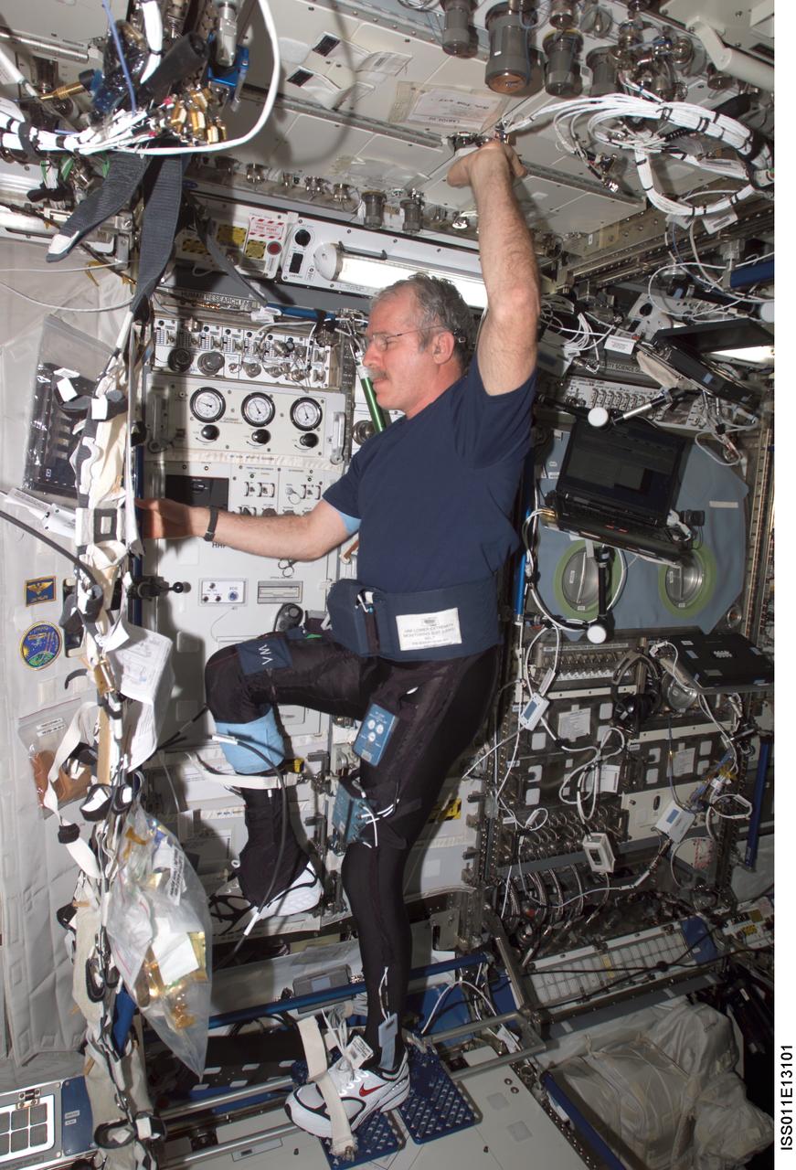
ISS011-E-13101 (16 Sept. 2005) --- Astronaut John L. Phillips, Expedition 11 NASA space station science officer and flight engineer, balances on the footplate of a special track attached to the Human Research Facility (HRF) rack in the Destiny laboratory on the International Space Station to perform Foot/Ground Reaction Forces During Spaceflight (FOOT) / Electromyography (EMG) calibration operations. Phillips is wearing the Lower Extremity Monitoring Suit (LEMS), the cycling tights outfitted with 20 sensors, which measures forces on joints and muscle activity.
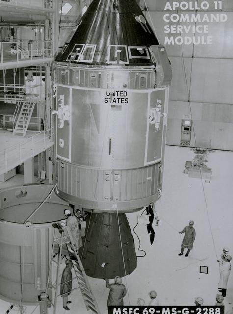
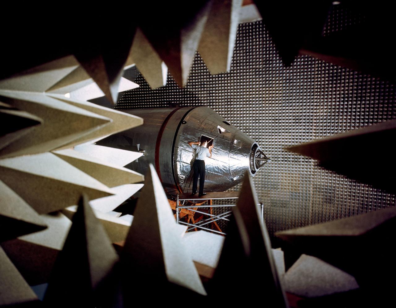
A close-up view of the Apollo 11 command service module ready to be mated with the spacecraft LEM adapter of the third stage. The towering 363-foot Saturn V was a multi-stage, multi-engine launch vehicle standing taller than the Statue of Liberty. Altogether, the Saturn V engines produced as much power as 85 Hoover Dams.
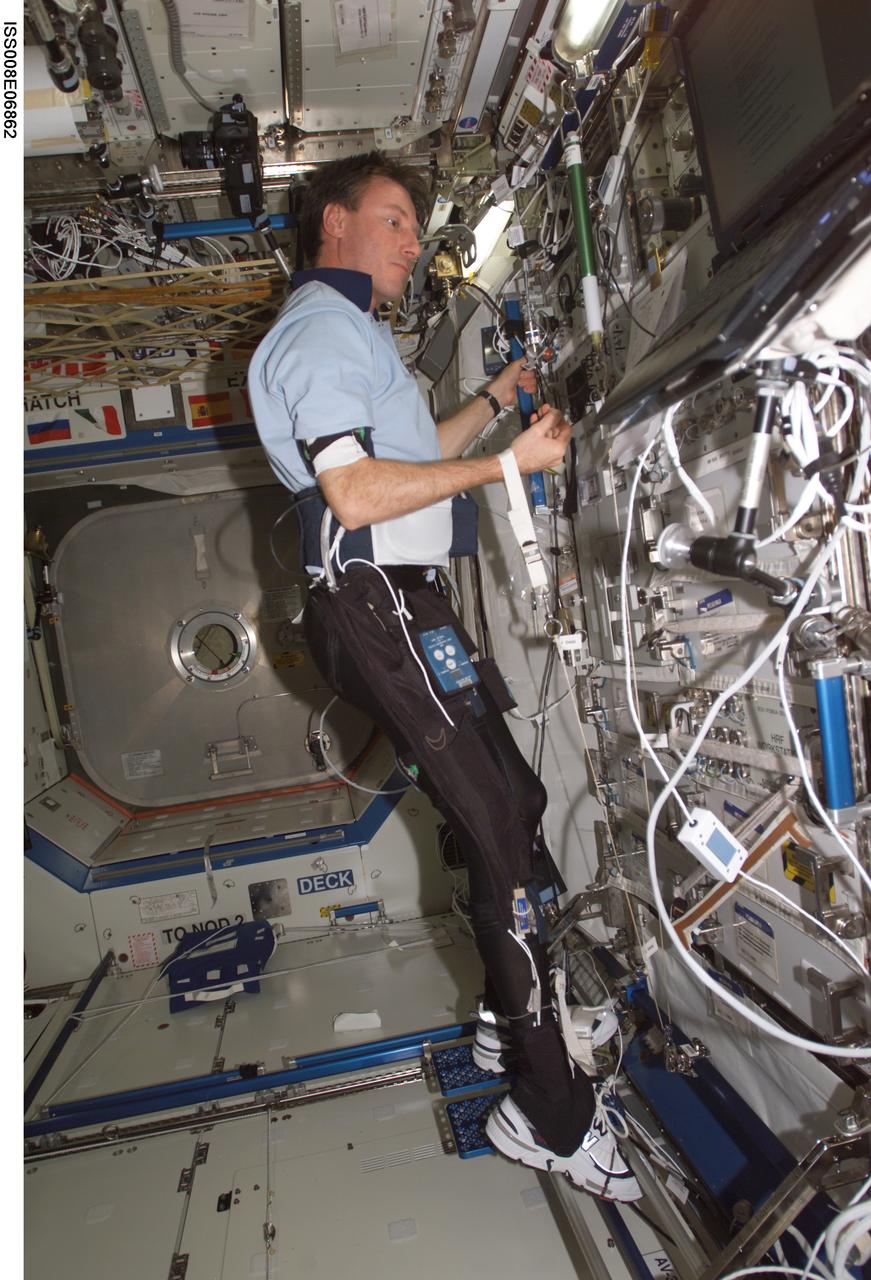
ISS008-E-06862 (3 December 2003) --- Astronaut C. Michael Foale, Expedition 8 mission commander and NASA ISS science officer, attired in instrumented biking tights, participates in the Foot/Ground Reaction Forces During Spaceflight (FOOT) experiment in the Destiny laboratory on the International Space Station (ISS). The Lower Extremity Monitoring Suit (LEMS), the cycling tights outfitted with 20 sensors, measured forces on Foale’s feet and joints and muscle activity while he went about his scheduled activities.
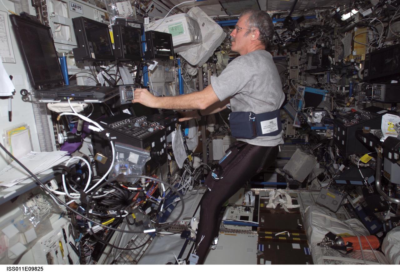
ISS011-E-09825 (29 June 2005) --- Astronaut John L. Phillips, Expedition 11 NASA Space Station science officer and flight engineer, enters data into a computer while participating in the Foot/Ground Reaction Forces During Spaceflight (FOOT) experiment in the Destiny laboratory of the International Space Station. Phillips wore the specially instrumented Lower Extremity Monitoring Suit (LEMS), cycling tights outfitted with sensors, during the experiment.
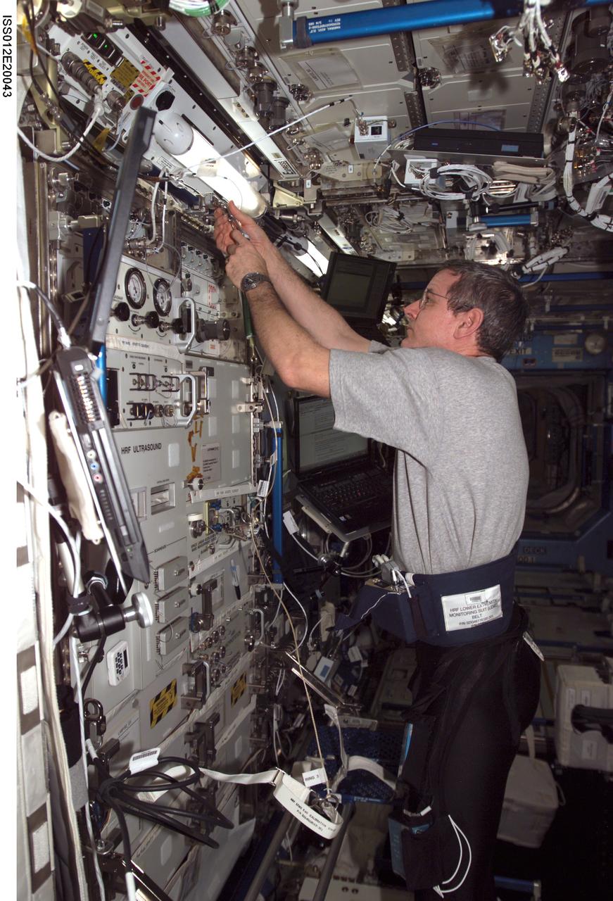
ISS012-E-20043 (9 March 2006) --- Astronaut William S. (Bill) McArthur, Expedition 12 commander and NASA space station science officer, sets up the electromyography (EMG) calibration cord assembly for a data collection session of the Foot/Ground Reaction Forces During Spaceflight (FOOT) experiment in the Destiny laboratory of the International Space Station. McArthur was attired in the specially instrumented Lower Extremity Monitoring Suit (LEMS), cycling tights outfitted with sensors for the experiment.
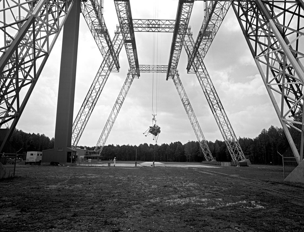
Lunar Landing Testing at NASA Langley. Lunar Landing Testing at NASA Langley. A simulated environment that contributed in a significant way to the success of Apollo project was the Lunar Landing Research Facility, an imposing 250 foot high, 400 foot long gantry structure that became operational in 1965. Published in the book "Space Flight Revolution" NASA SP-4308 pg. 376
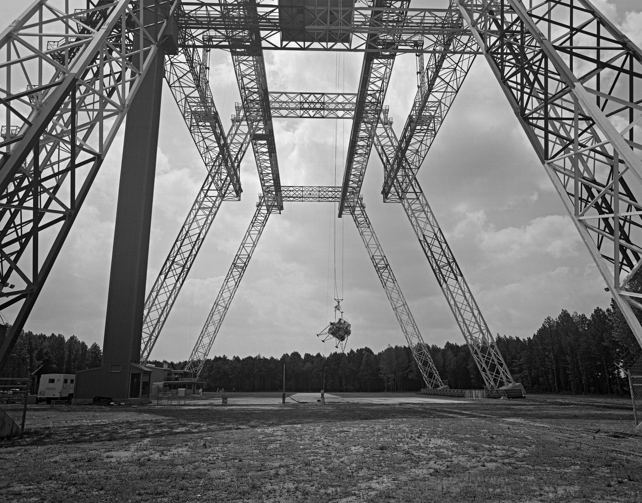
Lunar Landing Testing at NASA Langley. Lunar Landing Testing at NASA Langley. A simulated environment that contributed in a significant way to the success of Apollo project was the Lunar Landing Research Facility, an imposing 250 foot high, 400 foot long gantry structure that became operational in 1965. Published in the book "Space Flight Revolution" NASA SP-4308 pg. 376
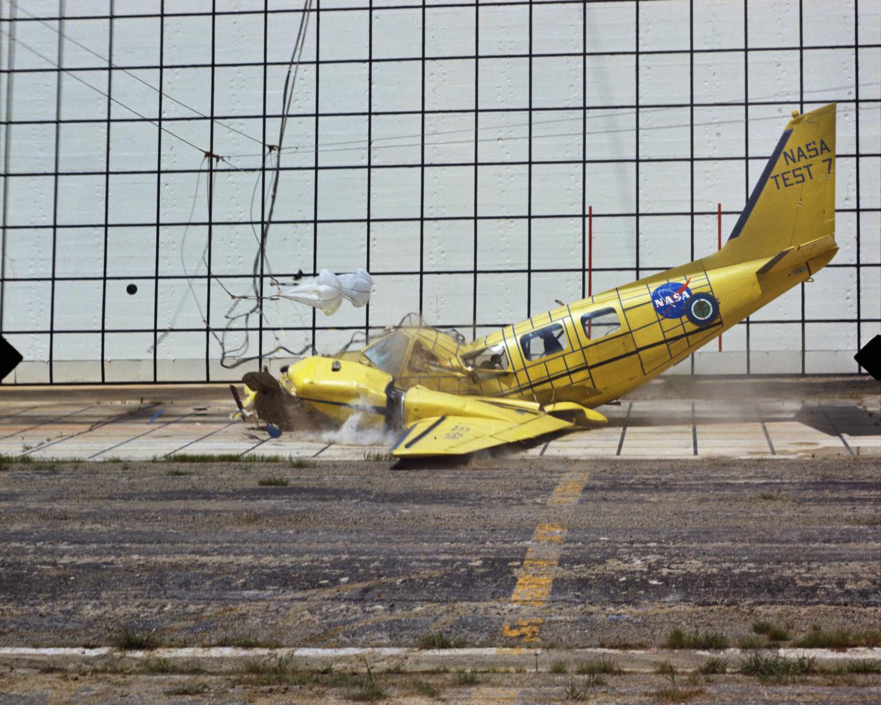
Photographed on: 08/03/75. -- By 1972 the Lunar Landing Research Facility was no longer in use for its original purpose. The 400-foot high structure was swiftly modified to allow engineers to study the dynamics of aircraft crashes. "The Impact Dynamics Research Facility is used to conduct crash testing of full-scale aircraft under controlled conditions. The aircraft are swung by cables from an A-frame structure that is approximately 400 ft. long and 230 foot high. The impact runway can be modified to simulate other grand crash environments, such as packed dirt, to meet a specific test requirement." "In 1972, NASA and the FAA embarked on a cooperative effort to develop technology for improved crashworthiness and passenger survivability in general aviation aircraft with little or no increase in weight and acceptable cost. Since then, NASA has "crashed" dozens of GA aircraft by using the lunar excursion module (LEM) facility originally built for the Apollo program." This photograph shows Crash Test No. 7. Crash Test: Test #7
Lunar Landing Testing at NASA Langley. Lunar Landing Testing at NASA Langley. A simulated environment that contributed in a significant way to the success of Apollo project was the Lunar Landing Research Facility, an imposing 250 foot high, 400 foot long gantry structure that became operational in 1965. Published in the book "Space Flight Revolution" NASA SP-4308 pg. 376
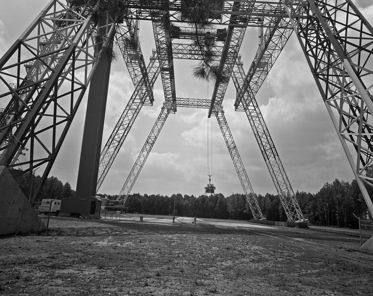
Lunar Landing Testing at NASA Langley. Lunar Landing Testing at NASA Langley. A simulated environment that contributed in a significant way to the success of Apollo project was the Lunar Landing Research Facility, an imposing 250 foot high, 400 foot long gantry structure that became operational in 1965. Published in the book "Space Flight Revolution" NASA SP-4308 pg. 376
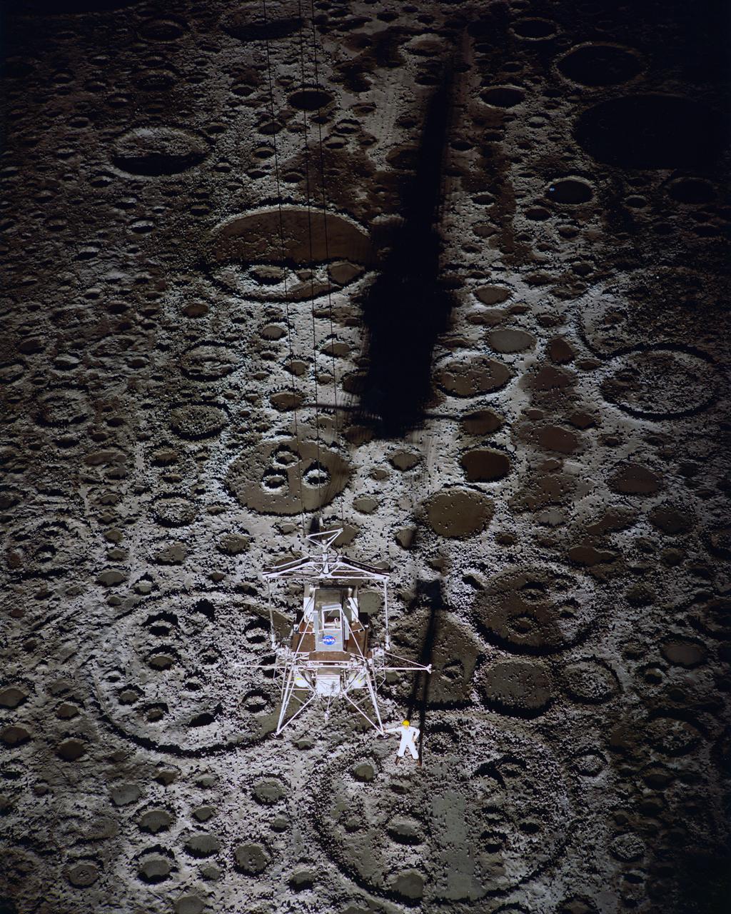
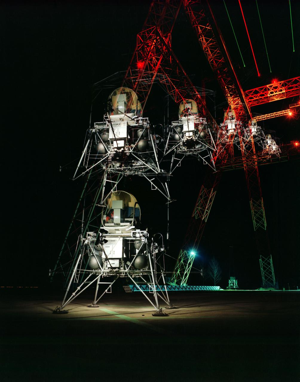
Lunar Landing Module photographed at night at the Lunar Landing Research Facility. Gantry facility 1297.
Lunar Landing Testing at NASA Langley. Lunar Landing Testing at NASA Langley. A simulated environment that contributed in a significant way to the success of Apollo project was the Lunar Landing Research Facility, an imposing 250 foot high, 400 foot long gantry structure that became operational in 1965. Published in the book "Space Flight Revolution" NASA SP-4308 pg. 376
Lunar Landing Testing at NASA Langley. Lunar Landing Testing at NASA Langley. A simulated environment that contributed in a significant way to the success of Apollo project was the Lunar Landing Research Facility, an imposing 250 foot high, 400 foot long gantry structure that became operational in 1965. Published in the book "Space Flight Revolution" NASA SP-4308 pg. 376
Lunar Landing Testing at NASA Langley. Lunar Landing Testing at NASA Langley. A simulated environment that contributed in a significant way to the success of Apollo project was the Lunar Landing Research Facility, an imposing 250 foot high, 400 foot long gantry structure that became operational in 1965. Published in the book "Space Flight Revolution" NASA SP-4308 pg. 376
Lunar Landing Testing at NASA Langley. Lunar Landing Testing at NASA Langley. A simulated environment that contributed in a significant way to the success of Apollo project was the Lunar Landing Research Facility, an imposing 250 foot high, 400 foot long gantry structure that became operational in 1965. Published in the book "Space Flight Revolution" NASA SP-4308 pg. 376
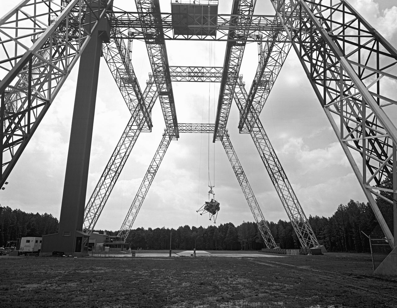
Lunar Landing Testing at NASA Langley. Lunar Landing Testing at NASA Langley. A simulated environment that contributed in a significant way to the success of Apollo project was the Lunar Landing Research Facility, an imposing 250 foot high, 400 foot long gantry structure that became operational in 1965. Published in the book "Space Flight Revolution" NASA SP-4308 pg. 376
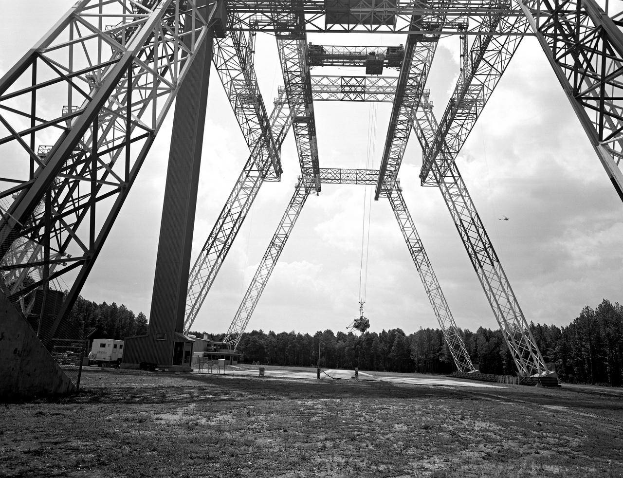
Lunar Landing Testing at NASA Langley. Lunar Landing Testing at NASA Langley. A simulated environment that contributed in a significant way to the success of Apollo project was the Lunar Landing Research Facility, an imposing 250 foot high, 400 foot long gantry structure that became operational in 1965. Published in the book "Space Flight Revolution" NASA SP-4308 pg. 376
Lunar Landing Testing at NASA Langley. Lunar Landing Testing at NASA Langley. A simulated environment that contributed in a significant way to the success of Apollo project was the Lunar Landing Research Facility, an imposing 250 foot high, 400 foot long gantry structure that became operational in 1965. Published in the book "Space Flight Revolution" NASA SP-4308 pg. 376
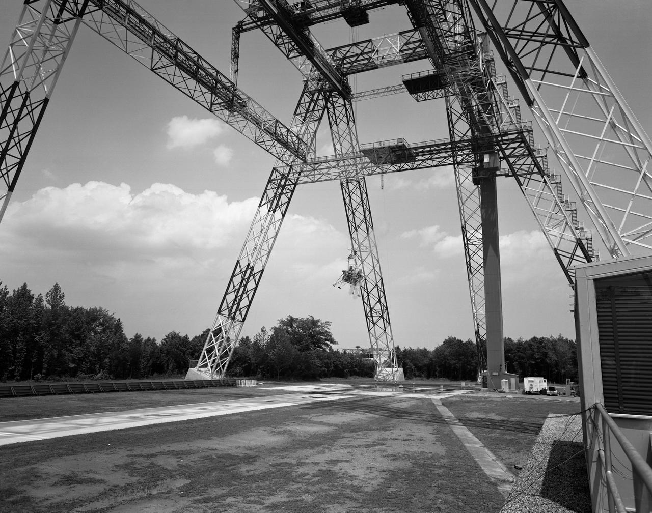
Lunar Landing Testing at NASA Langley. Lunar Landing Testing at NASA Langley. A simulated environment that contributed in a significant way to the success of Apollo project was the Lunar Landing Research Facility, an imposing 250 foot high, 400 foot long gantry structure that became operational in 1965. Published in the book "Space Flight Revolution" NASA SP-4308 pg. 376
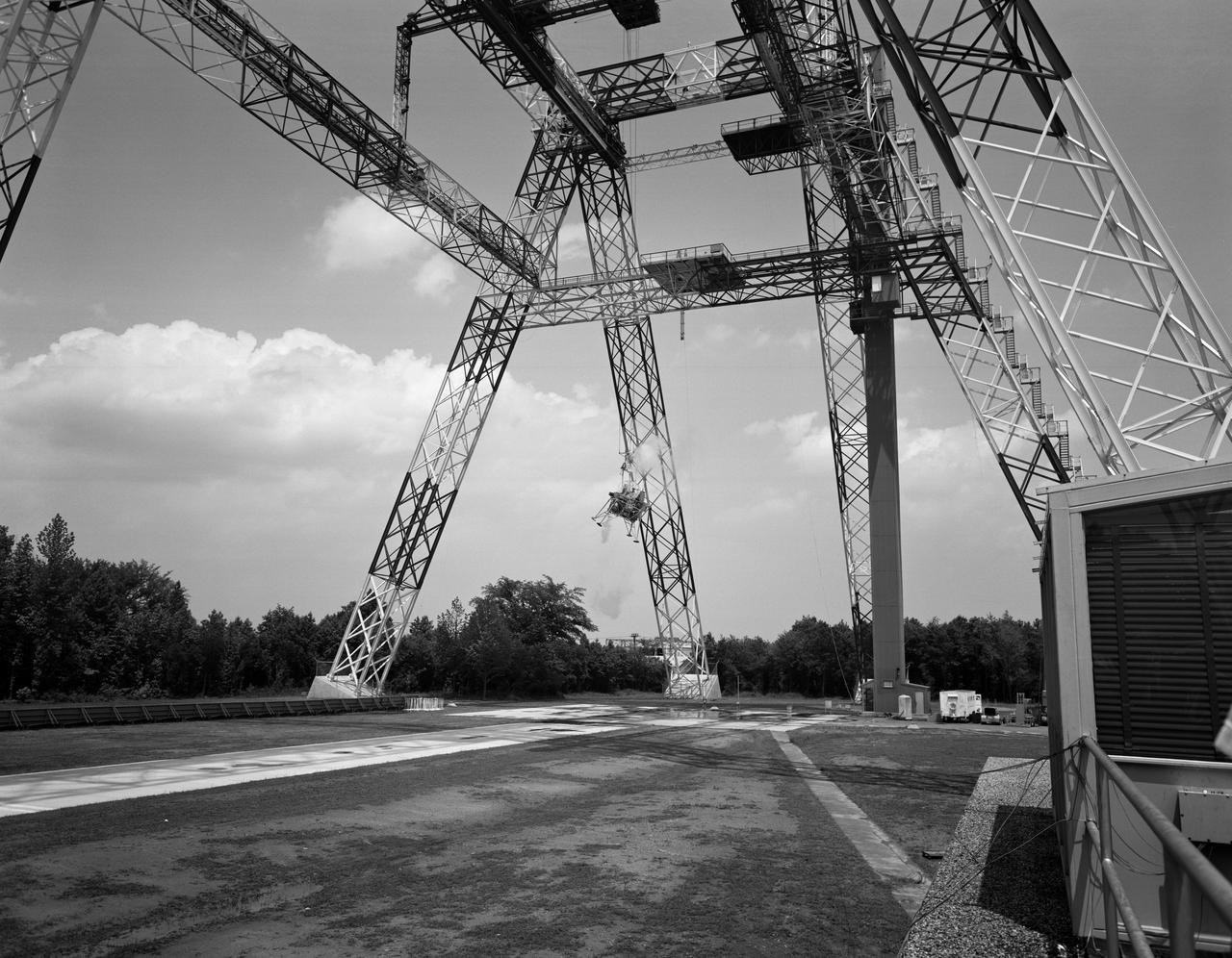
Lunar Landing Testing at NASA Langley. Lunar Landing Testing at NASA Langley. A simulated environment that contributed in a significant way to the success of Apollo project was the Lunar Landing Research Facility, an imposing 250 foot high, 400 foot long gantry structure that became operational in 1965. Published in the book "Space Flight Revolution" NASA SP-4308 pg. 376
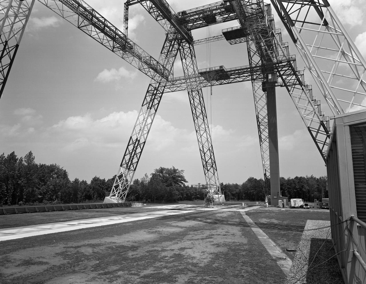
Lunar Landing Testing at NASA Langley. Lunar Landing Testing at NASA Langley. A simulated environment that contributed in a significant way to the success of Apollo project was the Lunar Landing Research Facility, an imposing 250 foot high, 400 foot long gantry structure that became operational in 1965. Published in the book "Space Flight Revolution" NASA SP-4308 pg. 376
Lunar Landing Testing at NASA Langley. Lunar Landing Testing at NASA Langley. A simulated environment that contributed in a significant way to the success of Apollo project was the Lunar Landing Research Facility, an imposing 250 foot high, 400 foot long gantry structure that became operational in 1965. Published in the book "Space Flight Revolution" NASA SP-4308 pg. 376
Lunar Landing Module photographed at night at the Lunar Landing Research Facility. Gantry facility 1297. Upright cockpit design lander over moonscape pavement at LLRF. 69-4872 was published in Winds of Change, 75th Anniversary Publication of NASA, P.88, by James Schultz.
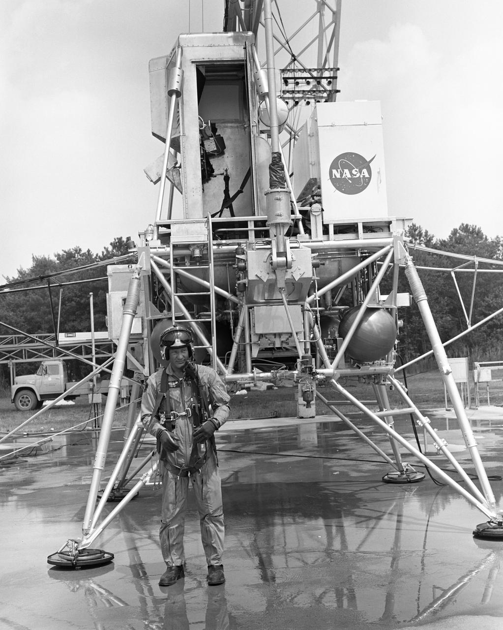
Astronaut Edwin Buzz Aldrin Lunar Module Pilot at the (LLRF) Lunar Landing Research Facility. Aldrin was one of the third group of astronauts named by NASA in October 1963. On November 11, 1966, he and command pilot James Lovell were launched into space in the Gemini 12 spacecraft on a 4-day flight, which brought the Gemini program to a successful close. Aldrin established a new record for extravehicular activity (EVA), spending 5-1/2 hours outside the spacecraft. He served as lunar module pilot for Apollo 11, July 16-24, 1969, the first manned lunar landing mission. Aldrin followed Neil Armstrong onto the lunar surface on July 20, 1969, completing a 2-hour and 15 minute lunar EVA. In July 1971, Aldrin resigned from NASA. Aldrin has logged 289 hours and 53 minutes in space, of which, 7 hours and 52 minutes were spent in EVA. https://www.nasa.gov/astronauts/biographies/former
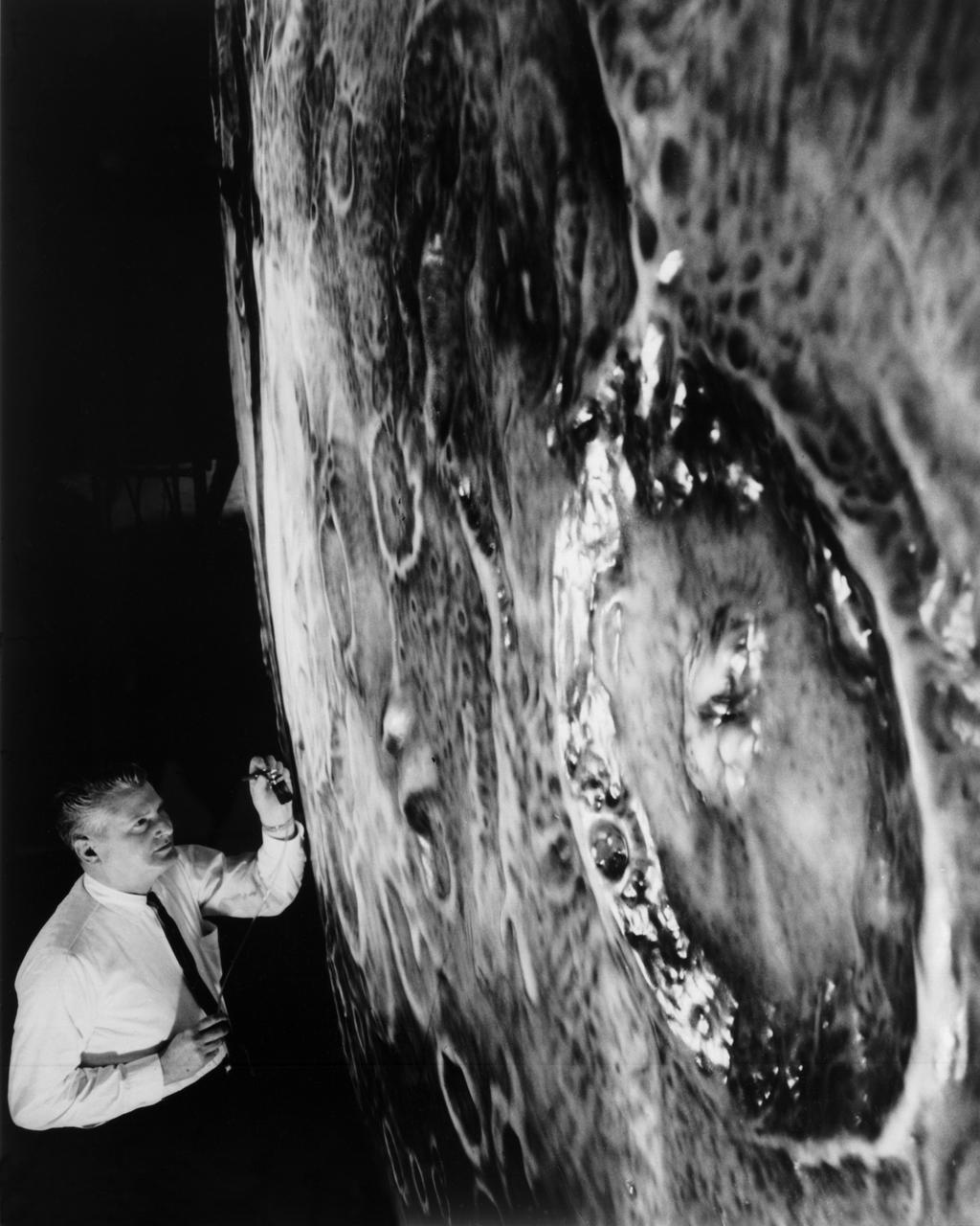
Artists used paintbrushes and airbrushes to recreate the lunar surface on each of the four models comprising the LOLA simulator. Project LOLA or Lunar Orbit and Landing Approach was a simulator built at Langley to study problems related to landing on the lunar surface. It was a complex project that cost nearly $2 million dollars. James Hansen wrote: "This simulator was designed to provide a pilot with a detailed visual encounter with the lunar surface; the machine consisted primarily of a cockpit, a closed-circuit TV system, and four large murals or scale models representing portions of the lunar surface as seen from various altitudes. The pilot in the cockpit moved along a track past these murals which would accustom him to the visual cues for controlling a spacecraft in the vicinity of the moon. Unfortunately, such a simulation--although great fun and quite aesthetic--was not helpful because flight in lunar orbit posed no special problems other than the rendezvous with the LEM, which the device did not simulate. Not long after the end of Apollo, the expensive machine was dismantled." (p. 379) Ellis J. White further described LOLA in his paper "Discussion of Three Typical Langley Research Center Simulation Programs," "Model 1 is a 20-foot-diameter sphere mounted on a rotating base and is scaled 1 in. = 9 miles. Models 2,3, and 4 are approximately 15x40 feet scaled sections of model 1. Model 4 is a scaled-up section of the Crater Alphonsus and the scale is 1 in. = 200 feet. All models are in full relief except the sphere." -- Published in James R. Hansen, Spaceflight Revolution: NASA Langley Research Center From Sputnik to Apollo, (Washington: NASA, 1995), p. 379; From Ellis J. White, "Discussion of Three Typical Langley Research Center Simulation Programs," Paper presented at the Eastern Simulation Council (EAI's Princeton Computation Center), Princeton, NJ, October 20, 1966.
Artists used paintbrushes and airbrushes to recreate the lunar surface on each of the four models comprising the LOLA simulator. Project LOLA or Lunar Orbit and Landing Approach was a simulator built at Langley to study problems related to landing on the lunar surface. It was a complex project that cost nearly 2 million dollars. James Hansen wrote: This simulator was designed to provide a pilot with a detailed visual encounter with the lunar surface the machine consisted primarily of a cockpit, a closed-circuit TV system, and four large murals or scale models representing portions of the lunar surface as seen from various altitudes. The pilot in the cockpit moved along a track past these murals which would accustom him to the visual cues for controlling a spacecraft in the vicinity of the moon. Unfortunately, such a simulation--although great fun and quite aesthetic--was not helpful because flight in lunar orbit posed no special problems other than the rendezvous with the LEM, which the device did not simulate. Not long after the end of Apollo, the expensive machine was dismantled. (p. 379) Ellis J. White described the simulator as follows: Model 1 is a 20-foot-diameter sphere mounted on a rotating base and is scaled 1 in. 9 miles. Models 2,3, and 4 are approximately 15x40 feet scaled sections of model 1. Model 4 is a scaled-up section of the Crater Alphonsus and the scale is 1 in. 200 feet. All models are in full relief except the sphere. -- Published in James R. Hansen, Spaceflight Revolution: NASA Langley Research Center From Sputnik to Apollo, (Washington: NASA, 1995), p. 379 Ellis J. White, Discussion of Three Typical Langley Research Center Simulation Programs, Paper presented at the Eastern Simulation Council (EAI s Princeton Computation Center), Princeton, NJ, October 20, 1966.
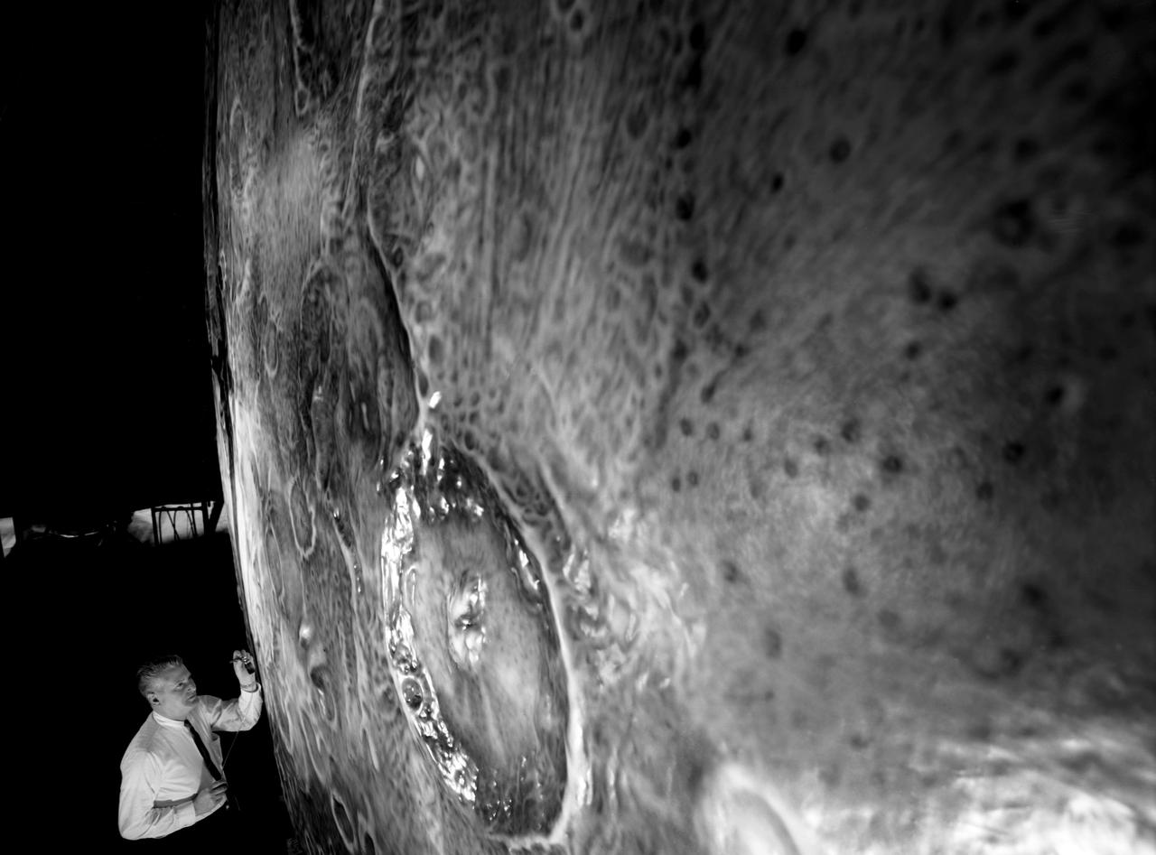
Artists used paintbrushes and airbrushes to recreate the lunar surface on each of the four models comprising the LOLA simulator. Project LOLA or Lunar Orbit and Landing Approach was a simulator built at Langley to study problems related to landing on the lunar surface. It was a complex project that cost nearly $2 million dollars. James Hansen wrote: "This simulator was designed to provide a pilot with a detailed visual encounter with the lunar surface; the machine consisted primarily of a cockpit, a closed-circuit TV system, and four large murals or scale models representing portions of the lunar surface as seen from various altitudes. The pilot in the cockpit moved along a track past these murals which would accustom him to the visual cues for controlling a spacecraft in the vicinity of the moon. Unfortunately, such a simulation--although great fun and quite aesthetic--was not helpful because flight in lunar orbit posed no special problems other than the rendezvous with the LEM, which the device did not simulate. Not long after the end of Apollo, the expensive machine was dismantled." (p. 379) Ellis J. White further described LOLA in his paper "Discussion of Three Typical Langley Research Center Simulation Programs," "Model 1 is a 20-foot-diameter sphere mounted on a rotating base and is scaled 1 in. = 9 miles. Models 2,3, and 4 are approximately 15x40 feet scaled sections of model 1. Model 4 is a scaled-up section of the Crater Alphonsus and the scale is 1 in. = 200 feet. All models are in full relief except the sphere." -- Published in James R. Hansen, Spaceflight Revolution: NASA Langley Research Center From Sputnik to Apollo, (Washington: NASA, 1995), p. 379; Ellis J. White, "Discussion of Three Typical Langley Research Center Simulation Programs," Paper presented at the Eastern Simulation Council (EAI's Princeton Computation Center), Princeton, NJ, October 20, 1966.
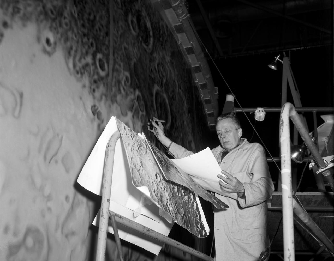
Artists used paintbrushes and airbrushes to recreate the lunar surface on each of the four models comprising the LOLA simulator. Project LOLA or Lunar Orbit and Landing Approach was a simulator built at Langley to study problems related to landing on the lunar surface. It was a complex project that cost nearly $2 million dollars. James Hansen wrote: "This simulator was designed to provide a pilot with a detailed visual encounter with the lunar surface; the machine consisted primarily of a cockpit, a closed-circuit TV system, and four large murals or scale models representing portions of the lunar surface as seen from various altitudes. The pilot in the cockpit moved along a track past these murals which would accustom him to the visual cues for controlling a spacecraft in the vicinity of the moon. Unfortunately, such a simulation--although great fun and quite aesthetic--was not helpful because flight in lunar orbit posed no special problems other than the rendezvous with the LEM, which the device did not simulate. Not long after the end of Apollo, the expensive machine was dismantled." (p. 379) Ellis J. White further described LOLA in his paper "Discussion of Three Typical Langley Research Center Simulation Programs," "Model 1 is a 20-foot-diameter sphere mounted on a rotating base and is scaled 1 in. = 9 miles. Models 2,3, and 4 are approximately 15x40 feet scaled sections of model 1. Model 4 is a scaled-up section of the Crater Alphonsus and the scale is 1 in. = 200 feet. All models are in full relief except the sphere." -- Published in James R. Hansen, Spaceflight Revolution, NASA SP-4308, p. 379; Ellis J. White, "Discussion of Three Typical Langley Research Center Simulation Programs," Paper presented at the Eastern Simulation Council (EAI's Princeton Computation Center), Princeton, NJ, October 20, 1966.

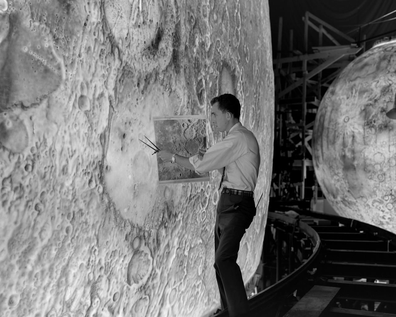
Project LOLA. Test subject sitting at the controls: Project LOLA or Lunar Orbit and Landing Approach was a simulator built at Langley to study problems related to landing on the lunar surface. It was a complex project that cost nearly 2 million dollars. James Hansen wrote: This simulator was designed to provide a pilot with a detailed visual encounter with the lunar surface the machine consisted primarily of a cockpit, a closed-circuit TV system, and four large murals or scale models representing portions of the lunar surface as seen from various altitudes. The pilot in the cockpit moved along a track past these murals which would accustom him to the visual cues for controlling a spacecraft in the vicinity of the moon. Unfortunately, such a simulation--although great fun and quite aesthetic--was not helpful because flight in lunar orbit posed no special problems other than the rendezvous with the LEM, which the device did not simulate. Not long after the end of Apollo, the expensive machine was dismantled. (p. 379) Ellis J. White wrote in his paper, Discussion of Three Typical Langley Research Center Simulation Programs : A typical mission would start with the first cart positioned on model 1 for the translunar approach and orbit establishment. After starting the descent, the second cart is readied on model 2 and, at the proper time, when superposition occurs, the pilot s scene is switched from model 1 to model 2. then cart 1 is moved to and readied on model 3. The procedure continues until an altitude of 150 feet is obtained. The cabin of the LM vehicle has four windows which represent a 45 degree field of view. The projection screens in front of each window represent 65 degrees which allows limited head motion before the edges of the display can be seen. The lunar scene is presented to the pilot by rear projection on the screens with four Schmidt television projectors. The attitude orientation of the vehicle is represented by changing the lunar scene through the portholes determined by the scan pattern of four orthicons. The stars are front projected onto the upper three screens with a four-axis starfield generation (starball) mounted over the cabin and there is a separate starball for the low window. -- Published in James R. Hansen, Spaceflight Revolution: NASA Langley Research Center From Sputnik to Apollo, (Washington: NASA, 1995), p. 379 Ellis J. White, Discussion of Three Typical Langley Research Center Simulation Programs, Paper presented at the Eastern Simulation Council (EAI s Princeton Computation Center), Princeton, NJ, October 20, 1966.
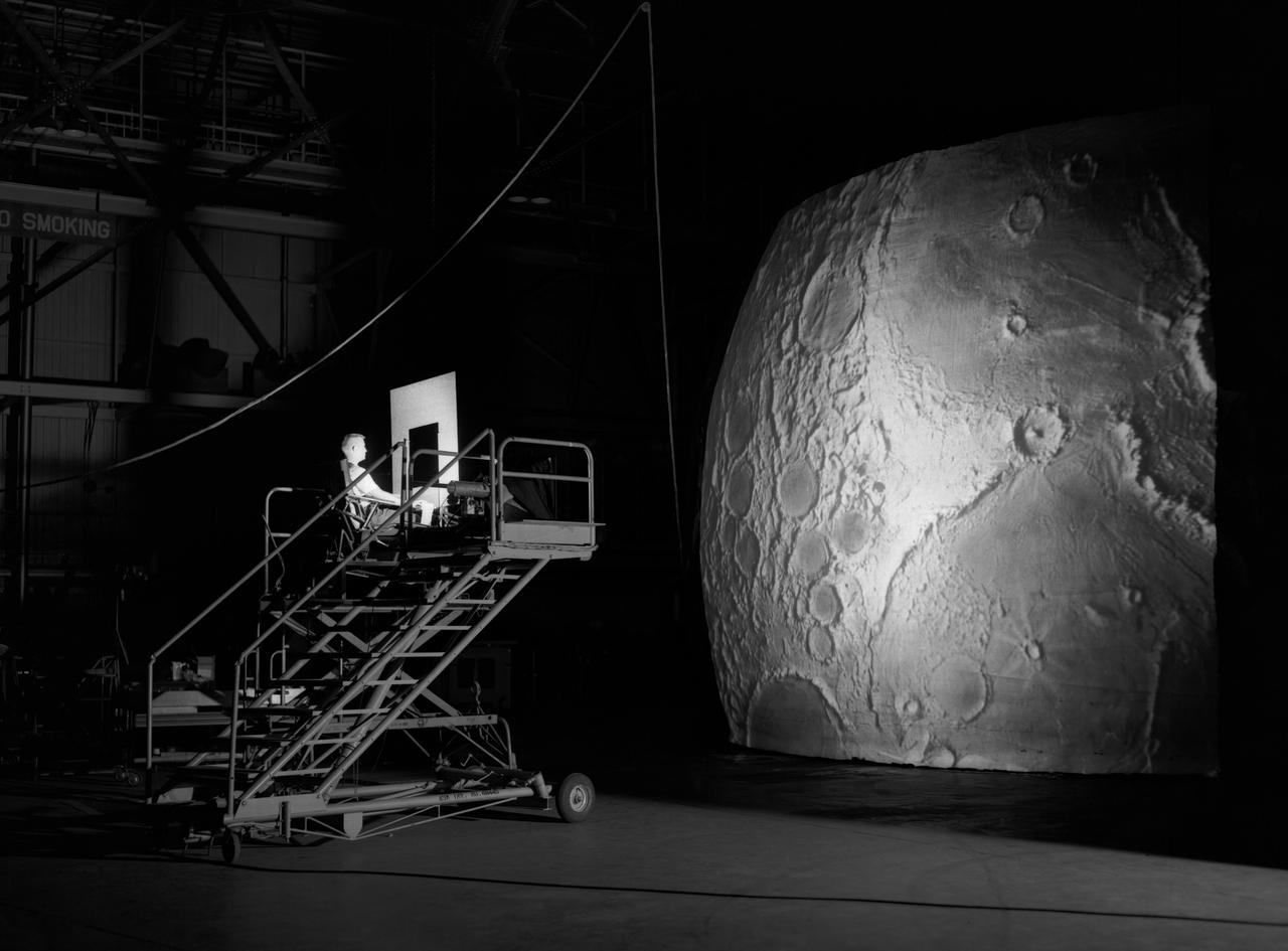
Test subject sitting at the controls: Project LOLA or Lunar Orbit and Landing Approach was a simulator built at Langley to study problems related to landing on the lunar surface. It was a complex project that cost nearly $2 million dollars. James Hansen wrote: "This simulator was designed to provide a pilot with a detailed visual encounter with the lunar surface; the machine consisted primarily of a cockpit, a closed-circuit TV system, and four large murals or scale models representing portions of the lunar surface as seen from various altitudes. The pilot in the cockpit moved along a track past these murals which would accustom him to the visual cues for controlling a spacecraft in the vicinity of the moon. Unfortunately, such a simulation--although great fun and quite aesthetic--was not helpful because flight in lunar orbit posed no special problems other than the rendezvous with the LEM, which the device did not simulate. Not long after the end of Apollo, the expensive machine was dismantled." (p. 379) Ellis J. White further described this simulator in his paper , "Discussion of Three Typical Langley Research Center Simulation Programs," (Paper presented at the Eastern Simulation Council (EAI's Princeton Computation Center), Princeton, NJ, October 20, 1966.) "A typical mission would start with the first cart positioned on model 1 for the translunar approach and orbit establishment. After starting the descent, the second cart is readied on model 2 and, at the proper time, when superposition occurs, the pilot's scene is switched from model 1 to model 2. then cart 1 is moved to and readied on model 3. The procedure continues until an altitude of 150 feet is obtained. The cabin of the LM vehicle has four windows which represent a 45 degree field of view. The projection screens in front of each window represent 65 degrees which allows limited head motion before the edges of the display can be seen. The lunar scene is presented to the pilot by rear projection on the screens with four Schmidt television projectors. The attitude orientation of the vehicle is represented by changing the lunar scene through the portholes determined by the scan pattern of four orthicons. The stars are front projected onto the upper three screens with a four-axis starfield generation (starball) mounted over the cabin and there is a separate starball for the low window." -- Published in James R. Hansen, Spaceflight Revolution: NASA Langley Research Center From Sputnik to Apollo, (Washington: NASA, 1995), p. 379.