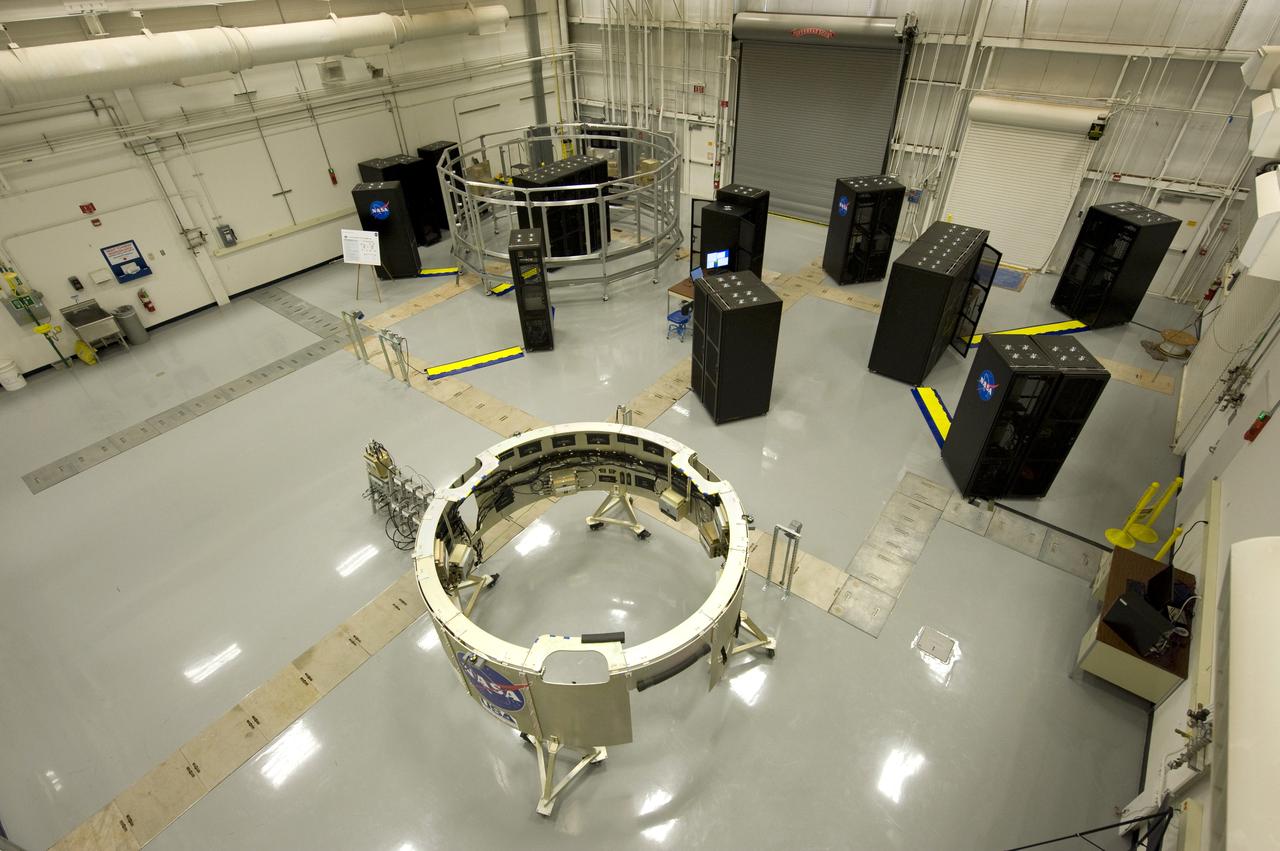
HARDWARE IN THE LOOP FACILITY
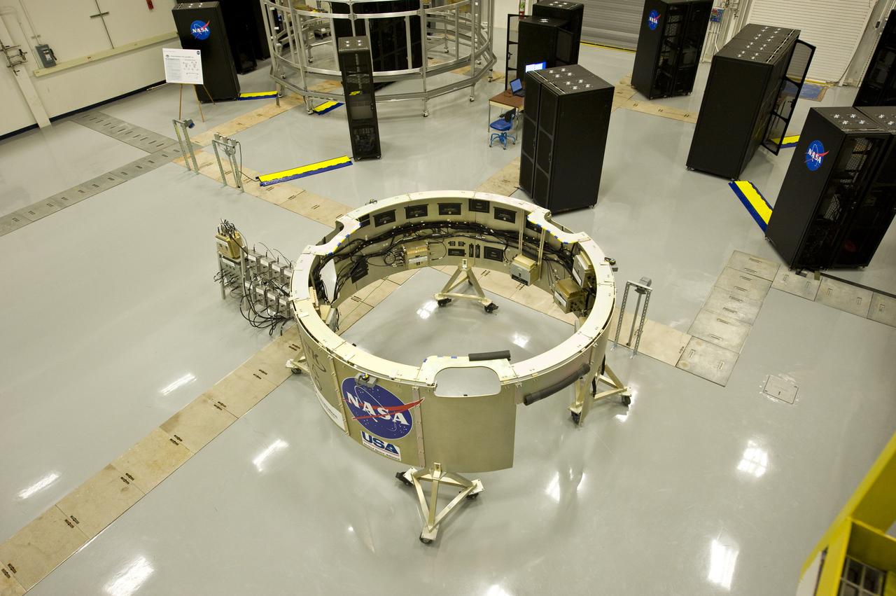
HARDWARE IN THE LOOP FACILITY
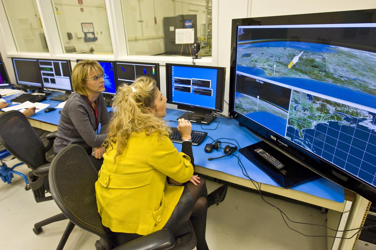
TVC TEST LAB/HARDWARE IN THE LOOP FACILITY FLIGHT SIMULATION CONTROL ROOM
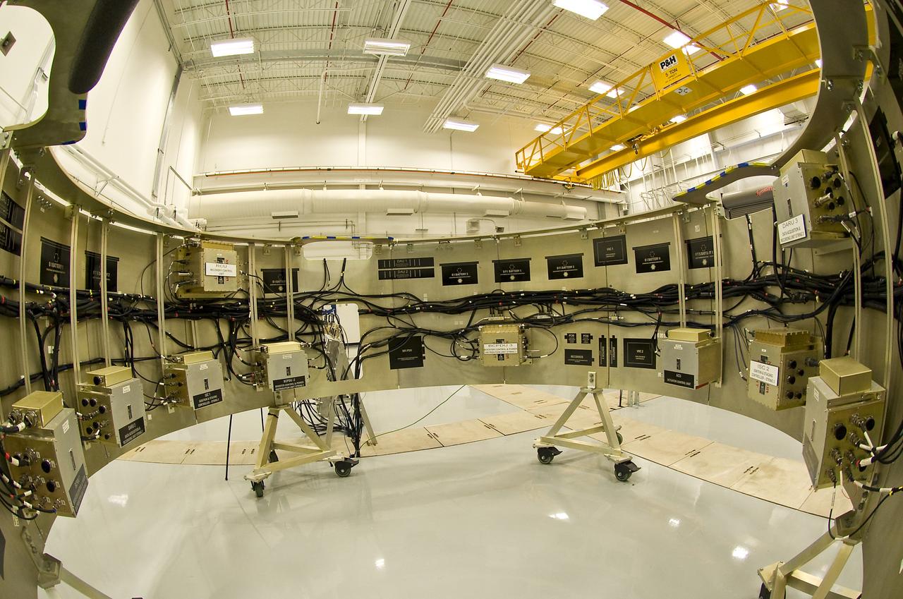
FIRST STAGE AVIONICS HARDWARE IN THE LOOP FACILITY
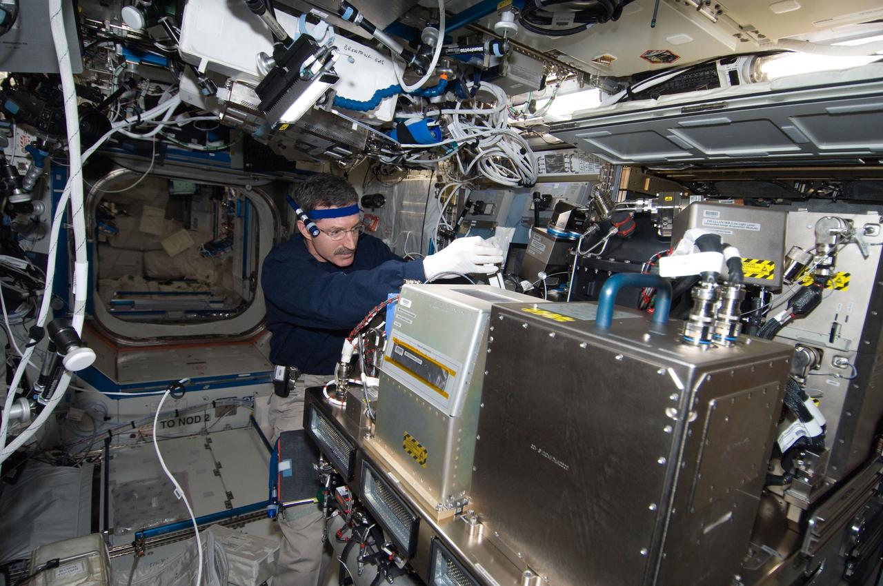
ISS030-E-234735 (10 April 2012) --- NASA astronaut Dan Burbank, Expedition 30 commander, works on the Combustion Integrated Rack (CIR) in the Destiny laboratory of the International Space Station. Burbank disconnected the Moderate Temperature Loop (MTL), Vacuum Exhaust System (VES) and station nitrogen lines of the Optics Bench, translated and rotated it out of the way and replaced a Fluids and Combustion Facility / Diagnostic Control Module (FCF DCM) on its back. Afterwards, Burbank returned the Optics Bench to its nominal position and reconnected the MTL, VES and station nitrogen lines.
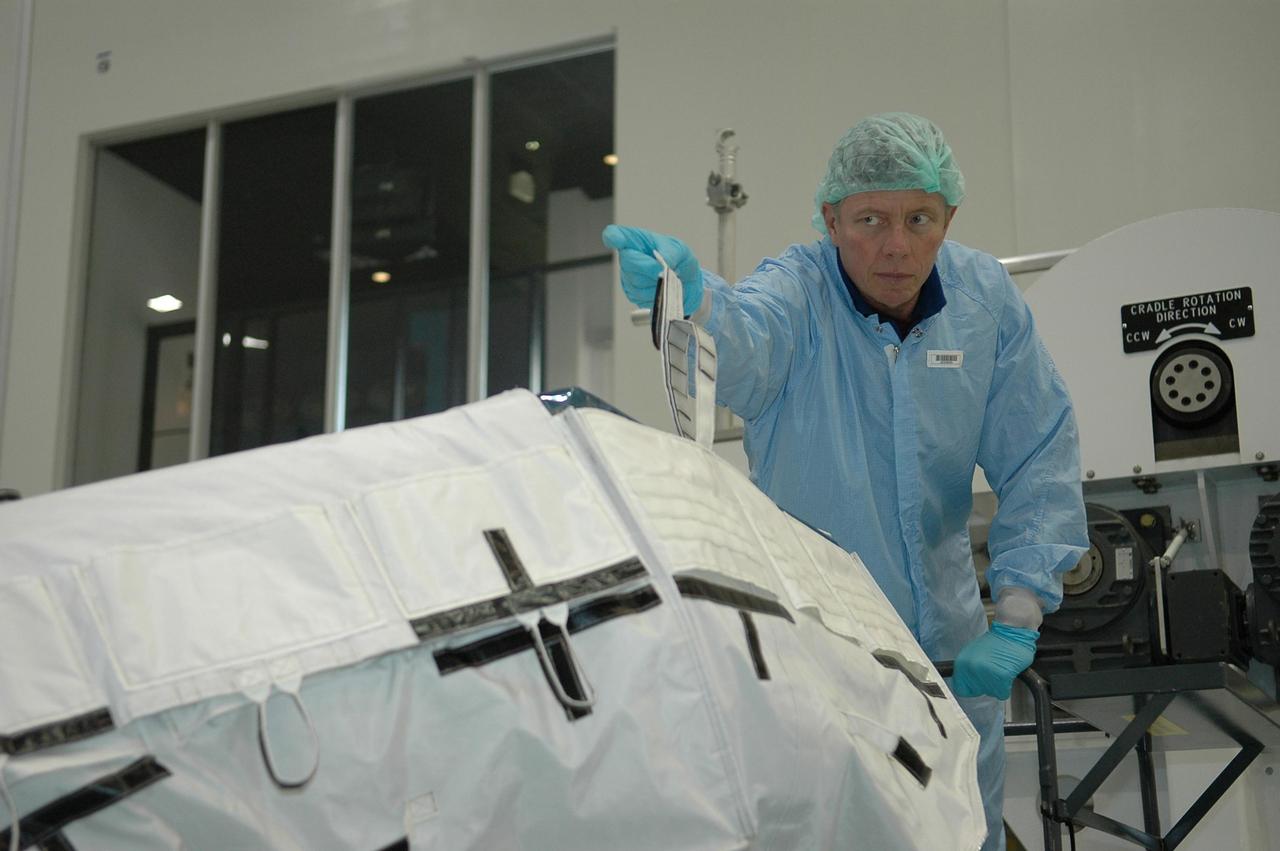
KENNEDY SPACE CENTER, FLA. - During a Crew Equipment Interface Test (CEIT) inside the Space Station Processing Facility at NASA's Kennedy Space Center, STS-121 Mission Specialist Michael Fossum holds a loop on a cover for the trailing umbilical system reel assembly that will be installed on the International Space Station during their mission. A CEIT provides hands-on experiences with equipment used on-orbit. Mission STS-121 is the second in the Return to Flight sequence and will carry on improvements that debuted during last year's STS-114 mission and build upon those tests. Launch is scheduled in July. Photo credit: NASA/Kim Shiflett
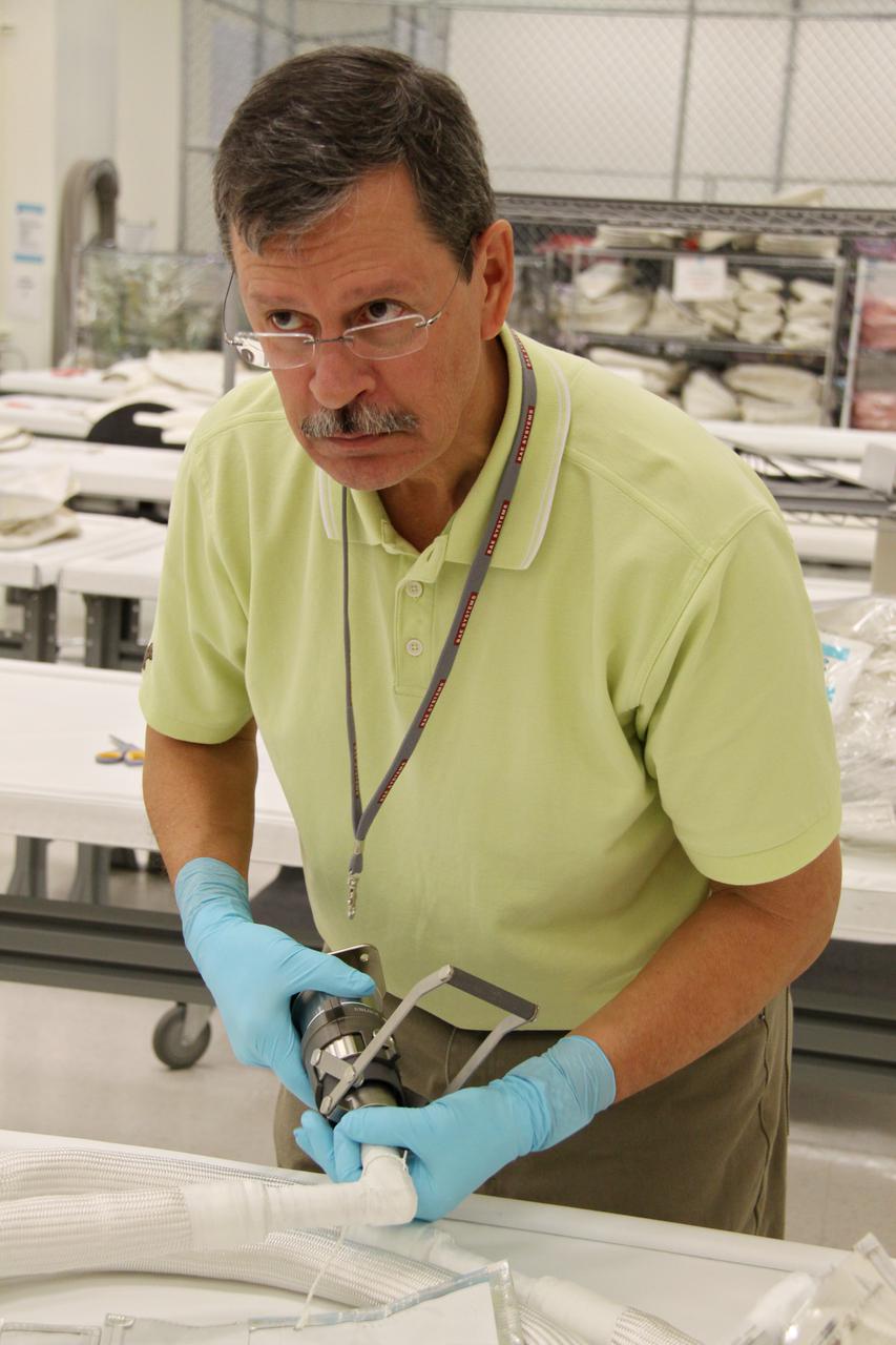
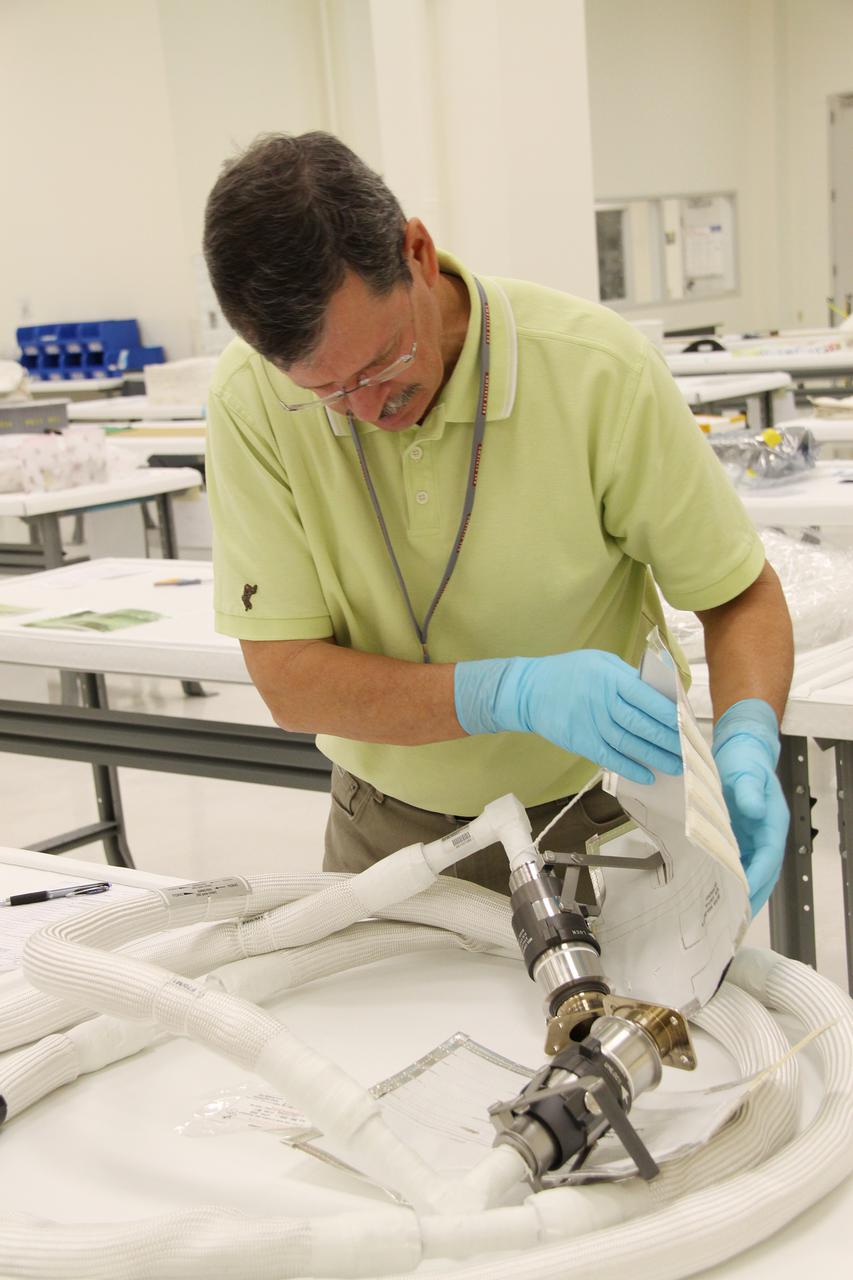
CAPE CANAVERAL, Fla. – In the Space Station Processing Facility at NASA's Kennedy Space Center in Florida, a worker inspects a newly arrived replacement high-pressure ammonia jumper hose to support space shuttle Endeavour's STS-130 mission. A problem arose during a prelaunch test Jan. 7 with one of four hoses that are needed to connect the ammonia loops of the International Space Station's Tranquility node to those of the Destiny laboratory. A decision was made to use an alternate hose design for use as the primary jumper. The new hoses are assembled from shorter hoses that were previously certified and tested. Connection of the modules requires two ammonia loops, with two lines apiece, each of which must be connected to both Tranquility and Destiny to route cooling to and from the Tranquility module. The primary payload for the STS-130 mission, Tranquility is a pressurized module that will provide additional room for crew members and many of the station's life support and environmental control systems. The node was built in Turin, Italy, by Thales Alenia Space for the European Space Agency. Endeavour's launch is set for Feb. 7. For information on the STS-130 mission and crew, visit http:__www.nasa.gov_mission_pages_shuttle_shuttlemissions_sts130_index.html. Photo credit: NASA_Jack Pfaller
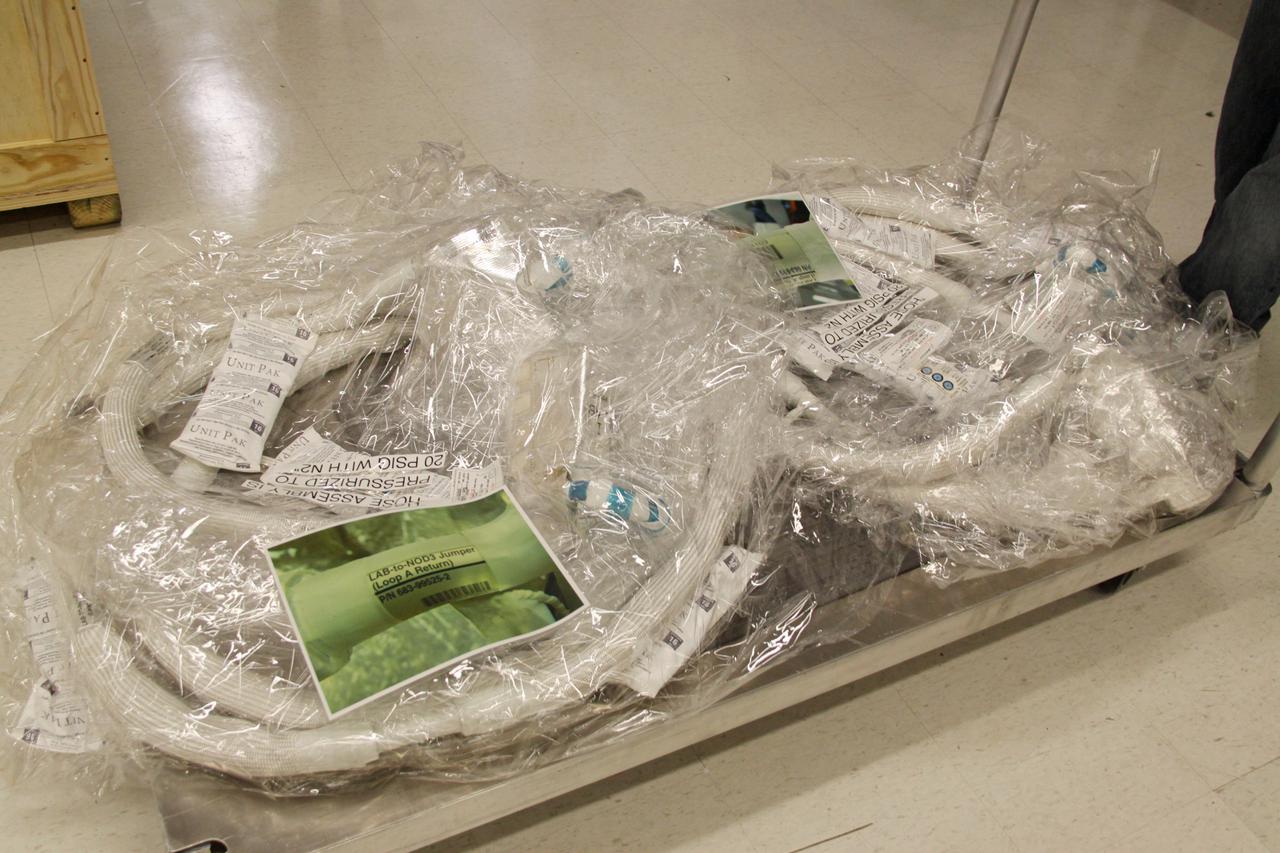
CAPE CANAVERAL, Fla. – The newly arrived replacement high-pressure ammonia jumper hoses to support space shuttle Endeavour's STS-130 mission are ready for processing in the Space Station Processing Facility at NASA's Kennedy Space Center in Florida. A problem arose during a prelaunch test Jan. 7 with one of four hoses that are needed to connect the ammonia loops of the International Space Station's Tranquility node to those of the Destiny laboratory. A decision was made to use an alternate hose design for use as the primary jumper. The new hoses are assembled from shorter hoses that were previously certified and tested. Connection of the modules requires two ammonia loops, with two lines apiece, each of which must be connected to both Tranquility and Destiny to route cooling to and from the Tranquility module. The primary payload for the STS-130 mission, Tranquility is a pressurized module that will provide additional room for crew members and many of the station's life support and environmental control systems. The node was built in Turin, Italy, by Thales Alenia Space for the European Space Agency. Endeavour's launch is set for Feb. 7. For information on the STS-130 mission and crew, visit http:__www.nasa.gov_mission_pages_shuttle_shuttlemissions_sts130_index.html. Photo credit: NASA_Jack Pfaller
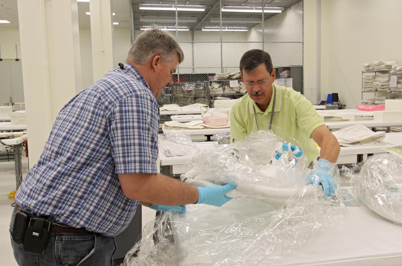
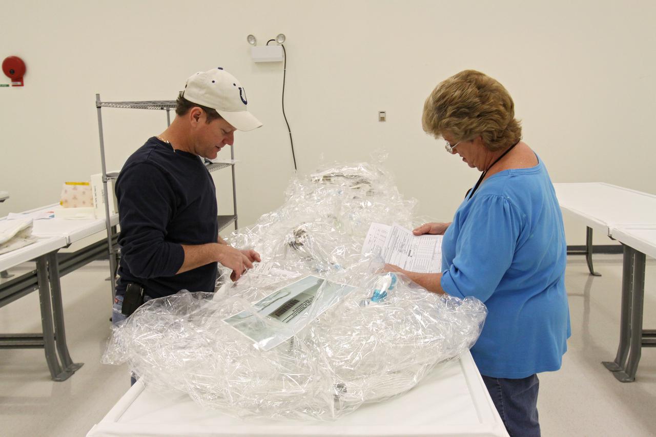
CAPE CANAVERAL, Fla. – In the Space Station Processing Facility at NASA's Kennedy Space Center in Florida, workers unwrap the newly arrived replacement high-pressure ammonia jumper hoses to support space shuttle Endeavour's STS-130 mission. A problem arose during a prelaunch test Jan. 7 with one of four hoses that are needed to connect the ammonia loops of the International Space Station's Tranquility node to those of the Destiny laboratory. A decision was made to use an alternate hose design for use as the primary jumper. The new hoses are assembled from shorter hoses that were previously certified and tested. Connection of the modules requires two ammonia loops, with two lines apiece, each of which must be connected to both Tranquility and Destiny to route cooling to and from the Tranquility module. The primary payload for the STS-130 mission, Tranquility is a pressurized module that will provide additional room for crew members and many of the station's life support and environmental control systems. The node was built in Turin, Italy, by Thales Alenia Space for the European Space Agency. Endeavour's launch is set for Feb. 7. For information on the STS-130 mission and crew, visit http:__www.nasa.gov_mission_pages_shuttle_shuttlemissions_sts130_index.html. Photo credit: NASA_Jack Pfaller
CAPE CANAVERAL, Fla. – In the Space Station Processing Facility at NASA's Kennedy Space Center in Florida, workers unwrap the newly arrived replacement high-pressure ammonia jumper hoses to support space shuttle Endeavour's STS-130 mission. A problem arose during a prelaunch test Jan. 7 with one of four hoses that are needed to connect the ammonia loops of the International Space Station's Tranquility node to those of the Destiny laboratory. A decision was made to use an alternate hose design for use as the primary jumper. The new hoses are assembled from shorter hoses that were previously certified and tested. Connection of the modules requires two ammonia loops, with two lines apiece, each of which must be connected to both Tranquility and Destiny to route cooling to and from the Tranquility module. The primary payload for the STS-130 mission, Tranquility is a pressurized module that will provide additional room for crew members and many of the station's life support and environmental control systems. The node was built in Turin, Italy, by Thales Alenia Space for the European Space Agency. Endeavour's launch is set for Feb. 7. For information on the STS-130 mission and crew, visit http:__www.nasa.gov_mission_pages_shuttle_shuttlemissions_sts130_index.html. Photo credit: NASA_Jack Pfaller

CAPE CANAVERAL, Fla. – In the Space Station Processing Facility at NASA's Kennedy Space Center in Florida, workers position along work tables the newly arrived replacement high-pressure ammonia jumper hoses to support space shuttle Endeavour's STS-130 mission. A problem arose during a prelaunch test Jan. 7 with one of four hoses that are needed to connect the ammonia loops of the International Space Station's Tranquility node to those of the Destiny laboratory. A decision was made to use an alternate hose design for use as the primary jumper. The new hoses are assembled from shorter hoses that were previously certified and tested. Connection of the modules requires two ammonia loops, with two lines apiece, each of which must be connected to both Tranquility and Destiny to route cooling to and from the Tranquility module. The primary payload for the STS-130 mission, Tranquility is a pressurized module that will provide additional room for crew members and many of the station's life support and environmental control systems. The node was built in Turin, Italy, by Thales Alenia Space for the European Space Agency. Endeavour's launch is set for Feb. 7. For information on the STS-130 mission and crew, visit http:__www.nasa.gov_mission_pages_shuttle_shuttlemissions_sts130_index.html. Photo credit: NASA_Jack Pfaller
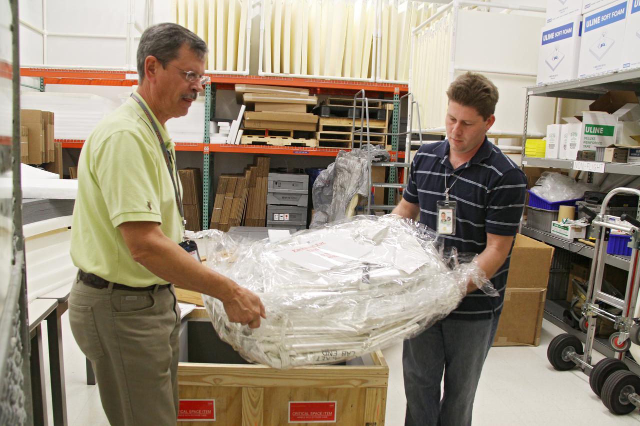
CAPE CANAVERAL, Fla. – Replacement high-pressure ammonia jumper hoses to support space shuttle Endeavour's STS-130 mission are unpacked from a transportation crate in the Space Station Processing Facility at NASA's Kennedy Space Center in Florida. A problem arose during a prelaunch test Jan. 7 with one of four hoses that are needed to connect the ammonia loops of the International Space Station's Tranquility node to those of the Destiny laboratory. A decision was made to use an alternate hose design for use as the primary jumper. The new hoses are assembled from shorter hoses that were previously certified and tested. Connection of the modules requires two ammonia loops, with two lines apiece, each of which must be connected to both Tranquility and Destiny to route cooling to and from the Tranquility module. The primary payload for the STS-130 mission, Tranquility is a pressurized module that will provide additional room for crew members and many of the station's life support and environmental control systems. The node was built in Turin, Italy, by Thales Alenia Space for the European Space Agency. Endeavour's launch is set for Feb. 7. For information on the STS-130 mission and crew, visit http:__www.nasa.gov_mission_pages_shuttle_shuttlemissions_sts130_index.html. Photo credit: NASA_Jack Pfaller
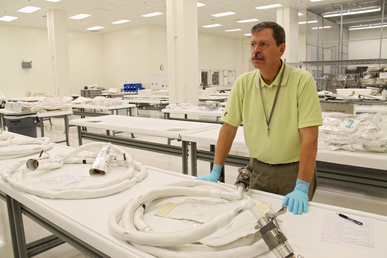
CAPE CANAVERAL, Fla. – In the Space Station Processing Facility at NASA's Kennedy Space Center in Florida, the newly arrived replacement high-pressure ammonia jumper hoses to support space shuttle Endeavour's STS-130 mission are positioned along work tables and ready for testing. A problem arose during a prelaunch test Jan. 7 with one of four hoses that are needed to connect the ammonia loops of the International Space Station's Tranquility node to those of the Destiny laboratory. A decision was made to use an alternate hose design for use as the primary jumper. The new hoses are assembled from shorter hoses that were previously certified and tested. Connection of the modules requires two ammonia loops, with two lines apiece, each of which must be connected to both Tranquility and Destiny to route cooling to and from the Tranquility module. The primary payload for the STS-130 mission, Tranquility is a pressurized module that will provide additional room for crew members and many of the station's life support and environmental control systems. The node was built in Turin, Italy, by Thales Alenia Space for the European Space Agency. Endeavour's launch is set for Feb. 7. For information on the STS-130 mission and crew, visit http:__www.nasa.gov_mission_pages_shuttle_shuttlemissions_sts130_index.html. Photo credit: NASA_Jack Pfaller
CAPE CANAVERAL, Fla. – In the Space Station Processing Facility at NASA's Kennedy Space Center in Florida, workers begin processing of the newly arrived replacement high-pressure ammonia jumper hoses to support space shuttle Endeavour's STS-130 mission. A problem arose during a prelaunch test Jan. 7 with one of four hoses that are needed to connect the ammonia loops of the International Space Station's Tranquility node to those of the Destiny laboratory. A decision was made to use an alternate hose design for use as the primary jumper. The new hoses are assembled from shorter hoses that were previously certified and tested. Connection of the modules requires two ammonia loops, with two lines apiece, each of which must be connected to both Tranquility and Destiny to route cooling to and from the Tranquility module. The primary payload for the STS-130 mission, Tranquility is a pressurized module that will provide additional room for crew members and many of the station's life support and environmental control systems. The node was built in Turin, Italy, by Thales Alenia Space for the European Space Agency. Endeavour's launch is set for Feb. 7. For information on the STS-130 mission and crew, visit http:__www.nasa.gov_mission_pages_shuttle_shuttlemissions_sts130_index.html. Photo credit: NASA_Jack Pfaller
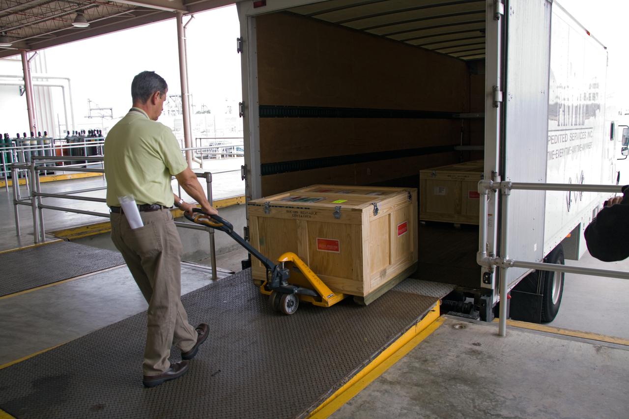
CAPE CANAVERAL, Fla. – Replacement high-pressure ammonia jumper hoses to support space shuttle Endeavour's STS-130 mission are delivered to the Space Station Processing Facility at NASA's Kennedy Space Center in Florida. A problem arose during a prelaunch test Jan. 7 with one of four hoses that are needed to connect the ammonia loops of the International Space Station's Tranquility node to those of the Destiny laboratory. A decision was made to use an alternate hose design for use as the primary jumper. The new hoses are assembled from shorter hoses that were previously certified and tested. Connection of the modules requires two ammonia loops, with two lines apiece, each of which must be connected to both Tranquility and Destiny to route cooling to and from the Tranquility module. The primary payload for the STS-130 mission, Tranquility is a pressurized module that will provide additional room for crew members and many of the station's life support and environmental control systems. The node was built in Turin, Italy, by Thales Alenia Space for the European Space Agency. Endeavour's launch is set for Feb. 7. For information on the STS-130 mission and crew, visit http:__www.nasa.gov_mission_pages_shuttle_shuttlemissions_sts130_index.html. Photo credit: NASA_Jack Pfaller
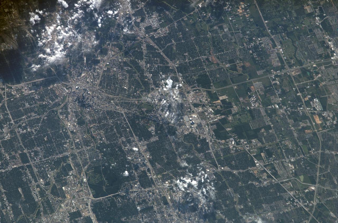
S115-E-06158 (15 Sept. 2006) --- This image of Houston's "downtown" and "uptown" districts and most of the area inside the I-610 Loop was photographed by one of the STS-115 crewmembers aboard the Space Shuttle Atlantis. Harris County Domed Stadium and the nearby facility for the National Football League's American Conference Houston representatives are just below the scattered cloud patch at frame center. What has become known as "uptown" Houston is in the lower left corner. The central business district or downtown is in the upper left quadrant, easily identified by the skyscrapers and the facilities for Houston's Major League Baseball and National Basketball Association affiliates. The Medical Center district is near the cloud patch just north of the older domed stadium. NASA is too far south to appear in the picture, though the southern leg of Beltway 8, about six miles north of the Johnson Space Center, appears at right edge; and Bush Intercontinental Airport is too far north.
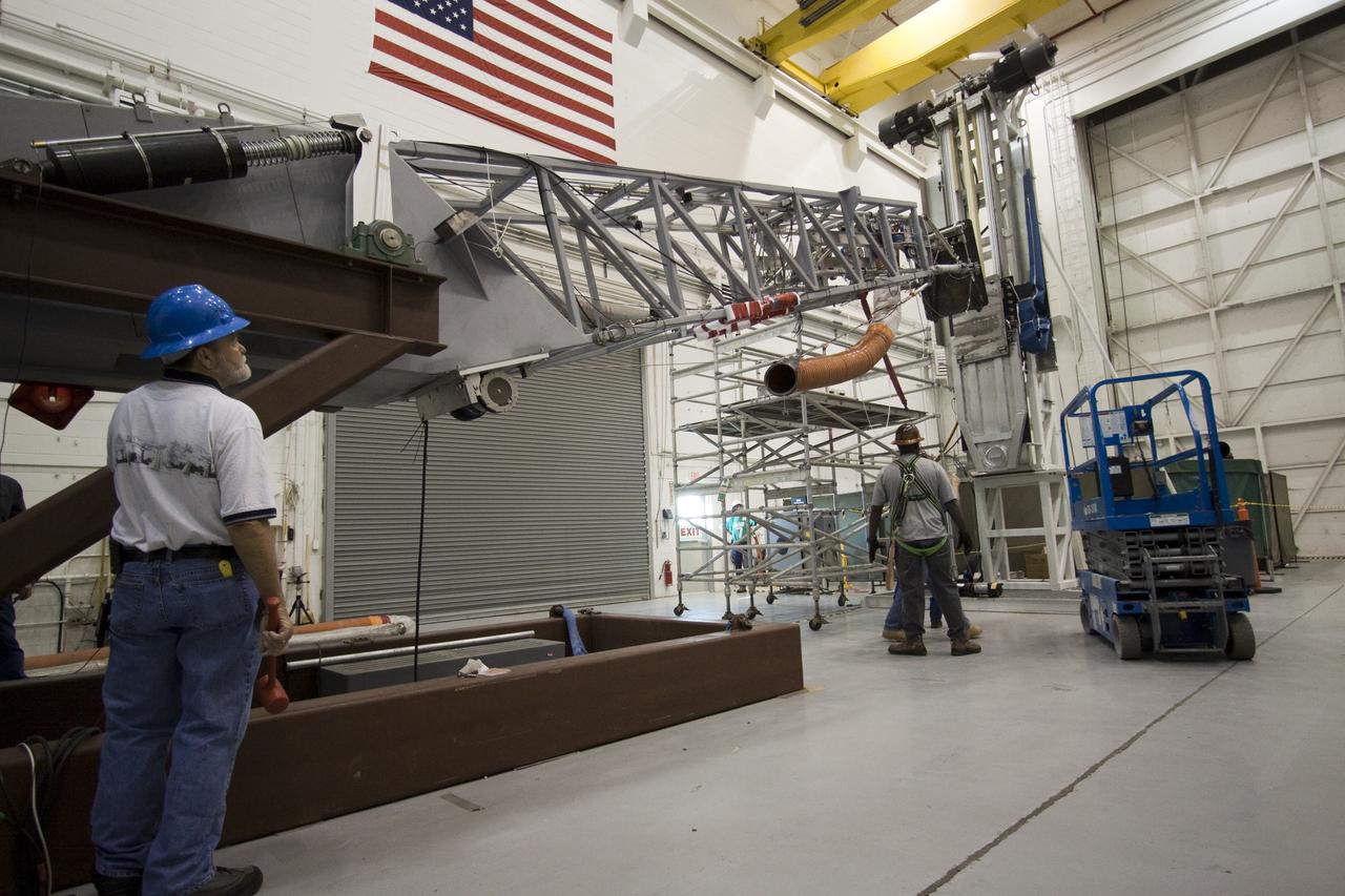
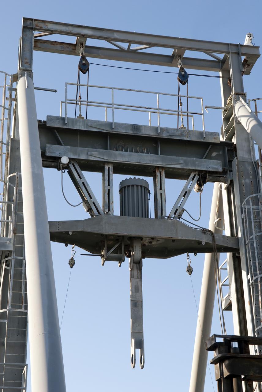
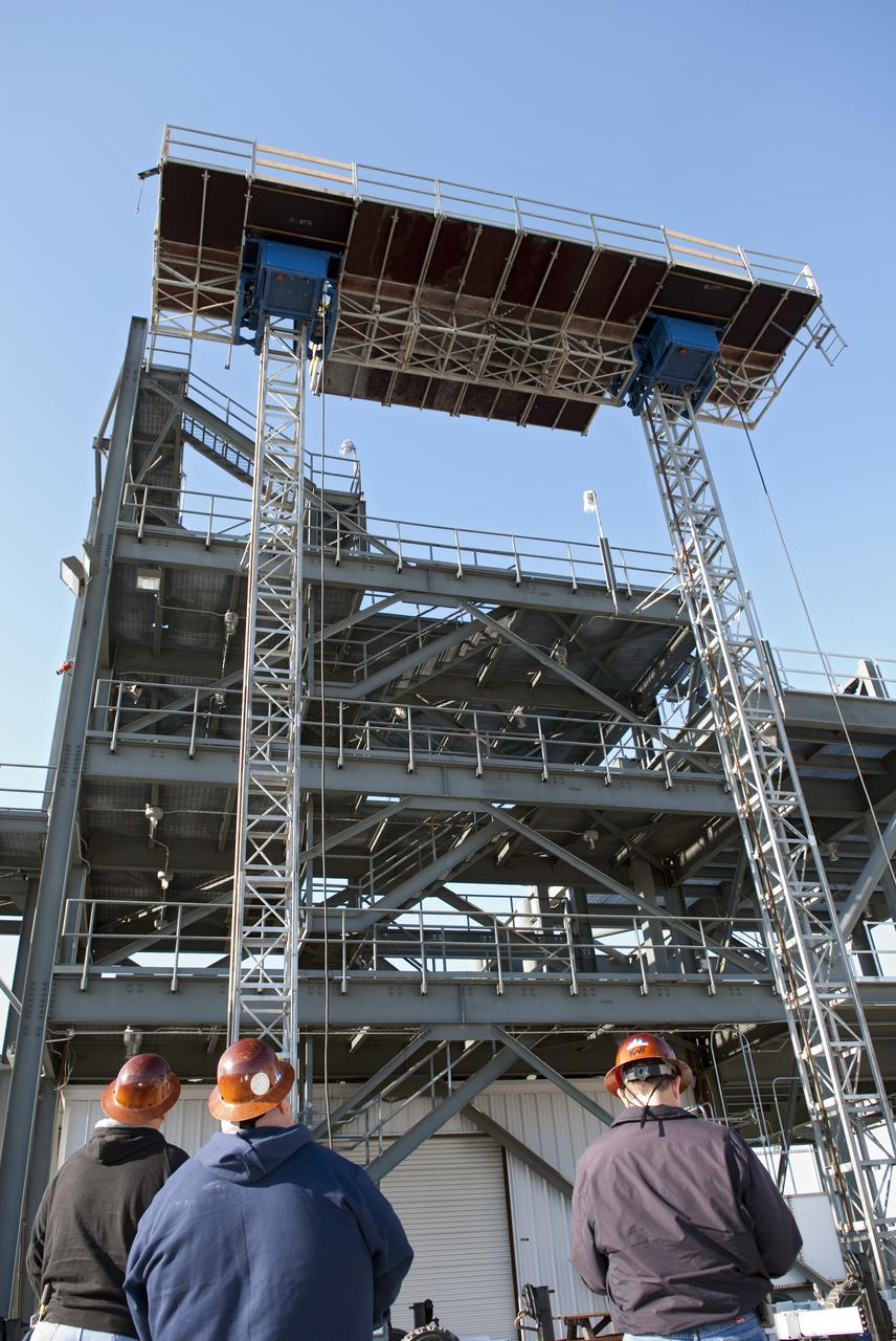
CAPE CANAVERAL, Fla. -- At NASA's Kennedy Space Center in Florida, testing of the Tilt-Up Umbilical Arm (TUUA) prototype's Environmental Control System Quick Disconnect takes place in the Launch Equipment Test Facility's 6,000-square-foot high bay. The prototype is used to demonstrate the safe disconnect and retraction of ground umbilical plates and associated hardware of a launch vehicle's upper stage and service module. The Environmental Control System consists of regulated air, which would be used to purge an inner tank and crew module. Since 1977, the facility has supported NASA’s Launch Services, shuttle, International Space Station, and Constellation programs, as well as commercial providers. The facility recently underwent a major upgrade to support even more programs, projects and customers. It houses a cable fabrication and molding shop, pneumatics shop, machine and weld shop and full-scale control room. Outside, the facility features a water flow test loop, vehicle motion simulator, 600-ton test fixture, launch simulation towers and a cryogenic system. Photo credit: NASA/Jack Pfaller
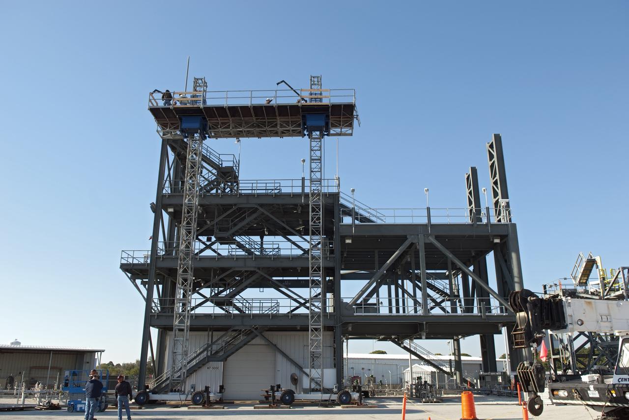
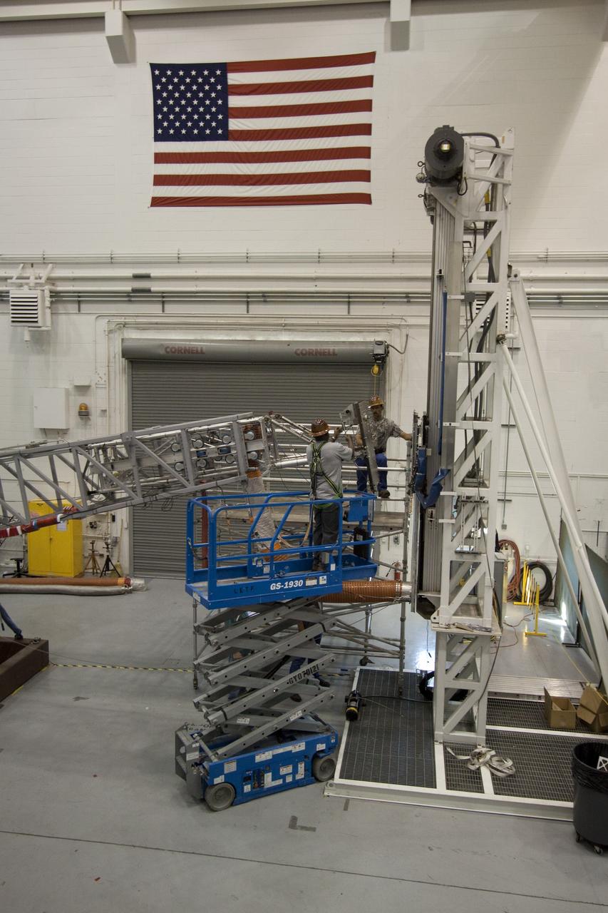
CAPE CANAVERAL, Fla. -- At NASA's Kennedy Space Center in Florida, workers receive training atop a mast climber that is attached to launch simulation towers outside the Launch Equipment Test Facility. The training includes attaching carrier plates, water and air systems, and electricity to the climber to simulate working in Kennedy's Vehicle Assembly Building (VAB). Mast climbers can be substituted for fixed service structures currently inside the VAB to provide access to any type of launch vehicle. Since 1977, the facility has supported NASA’s Launch Services, shuttle, International Space Station, and Constellation programs, as well as commercial providers. Last year, the facility underwent a major upgrade to support even more programs, projects and customers. It houses a 6,000-square-foot high bay, cable fabrication and molding shop, pneumatics shop, machine and weld shop and full-scale control room. Outside, the facility features a water flow test loop, vehicle motion simulator and a cryogenic system. Photo credit: NASA/Jim Grossmann
CAPE CANAVERAL, Fla. -- At NASA's Kennedy Space Center in Florida, testing of the Tilt-Up Umbilical Arm (TUUA) prototype's Environmental Control System Quick Disconnect takes place in the Launch Equipment Test Facility's 6,000-square-foot high bay. The prototype is used to demonstrate the safe disconnect and retraction of ground umbilical plates and associated hardware of a launch vehicle's upper stage and service module. The Environmental Control System consists of regulated air, which would be used to purge an inner tank and crew module. Since 1977, the facility has supported NASA’s Launch Services, shuttle, International Space Station, and Constellation programs, as well as commercial providers. The facility recently underwent a major upgrade to support even more programs, projects and customers. It houses a cable fabrication and molding shop, pneumatics shop, machine and weld shop and full-scale control room. Outside, the facility features a water flow test loop, vehicle motion simulator, 600-ton test fixture, launch simulation towers and a cryogenic system. Photo credit: NASA/Jack Pfaller

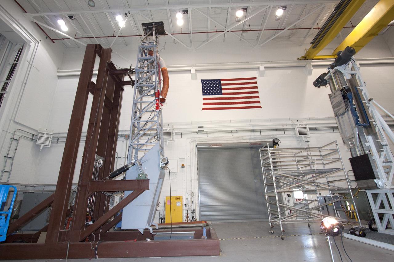
CAPE CANAVERAL, Fla. -- At NASA's Kennedy Space Center in Florida, the 600-Ton Test Fixture outside the Launch Equipment Test Facility conducts a 500,000-pound pull test of a bridge crane lifting element, which is used to lift space shuttles in the Vehicle Assembly Building. The fixture proofload tests, in tension and compression, a variety of ground support equipment, including slings, lifting beams and other critical lifting hardware that require periodic proofloading. Since 1977, the facility has supported NASA’s Launch Services, shuttle, International Space Station, and Constellation programs, as well as commercial providers. The facility recently underwent a major upgrade to support even more programs, projects and customers. It houses a 6,000-square-foot high bay, cable fabrication and molding shop, pneumatics shop, machine and weld shop and full-scale control room. Outside, the facility features a water flow test loop, vehicle motion simulator, launch simulation towers and a cryogenic system. Photo credit: NASA/Jim Grossmann
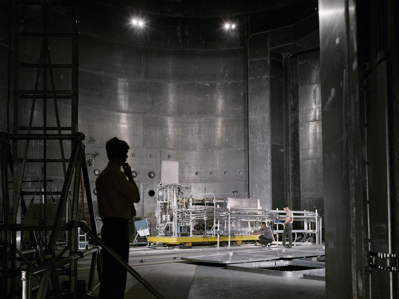
Set up of a Brayton Cycle Power System test in the Space Power Facility’s massive vacuum chamber at the National Aeronautics and Space Administration’s (NASA) Plum Brook Station in Sandusky, Ohio. The $28.4-million facility, which began operations in 1969, is the largest high vacuum chamber ever built. The chamber is 100 feet in diameter and 120 feet high. It can produce a vacuum deep enough to simulate the conditions at 300 miles altitude. The Space Power Facility was originally designed to test nuclear-power sources for spacecraft, but it was never used for that purpose. The Space Power Facility was first used to test a 15 to 20-kilowatt Brayton Cycle Power System for space applications. Three different methods of simulating solar heat were employed during the tests. Lewis researchers studied the Brayton power system extensively in the 1960s and 1970s. The Brayton engine converted solar thermal energy into electrical power. The system operated on a closed-loop Brayton thermodynamic cycle with a helium-xenon gas mixture as its working fluid. A space radiator was designed to serve as the system’s waste heat rejecter. The radiator was later installed in the vacuum chamber and tested in a simulated space environment to determine its effect on the power conversion system. The Brayton system was subjected to simulated orbits with 62 minutes of sun and 34 minutes of shade.
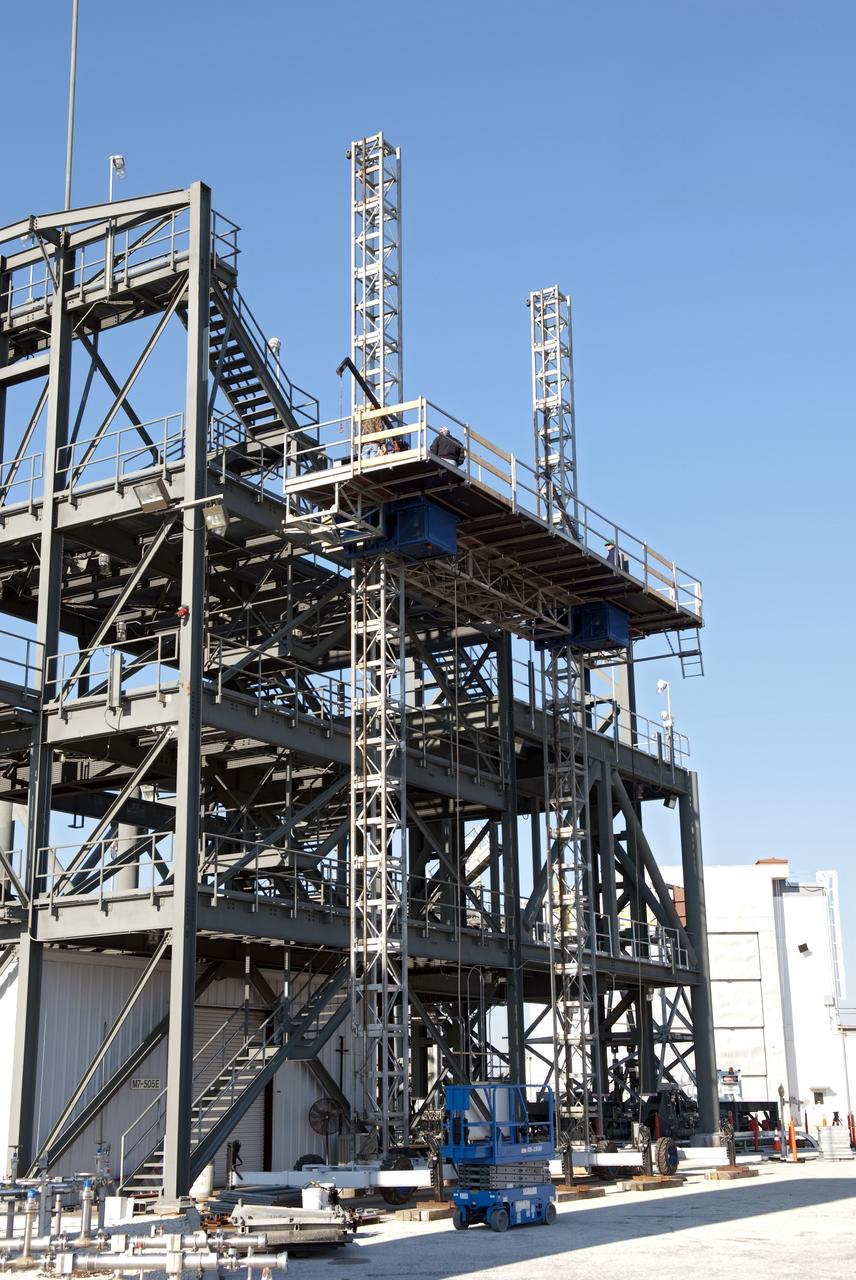
CAPE CANAVERAL, Fla. -- At NASA's Kennedy Space Center in Florida, workers receive training atop a mast climber that is attached to launch simulation towers outside the Launch Equipment Test Facility. The training includes attaching carrier plates, water and air systems, and electricity to the climber to simulate working in Kennedy's Vehicle Assembly Building (VAB). Mast climbers can be substituted for fixed service structures currently inside the VAB to provide access to any type of launch vehicle. Since 1977, the facility has supported NASA’s Launch Services, shuttle, International Space Station, and Constellation programs, as well as commercial providers. Last year, the facility underwent a major upgrade to support even more programs, projects and customers. It houses a 6,000-square-foot high bay, cable fabrication and molding shop, pneumatics shop, machine and weld shop and full-scale control room. Outside, the facility features a water flow test loop, vehicle motion simulator and a cryogenic system. Photo credit: NASA/Jim Grossmann
CAPE CANAVERAL, Fla. -- At NASA's Kennedy Space Center in Florida, the 600-Ton Test Fixture outside the Launch Equipment Test Facility is prepared to conduct a 500,000-pound pull test of a bridge crane lifting element, which is used to lift space shuttles in the Vehicle Assembly Building. The fixture proofload tests, in tension and compression, a variety of ground support equipment, including slings, lifting beams and other critical lifting hardware that require periodic proofloading. Since 1977, the facility has supported NASA’s Launch Services, shuttle, International Space Station, and Constellation programs, as well as commercial providers. The facility recently underwent a major upgrade to support even more programs, projects and customers. It houses a 6,000-square-foot high bay, cable fabrication and molding shop, pneumatics shop, machine and weld shop and full-scale control room. Outside, the facility features a water flow test loop, vehicle motion simulator, launch simulation towers and a cryogenic system. Photo credit: NASA/Jim Grossmann
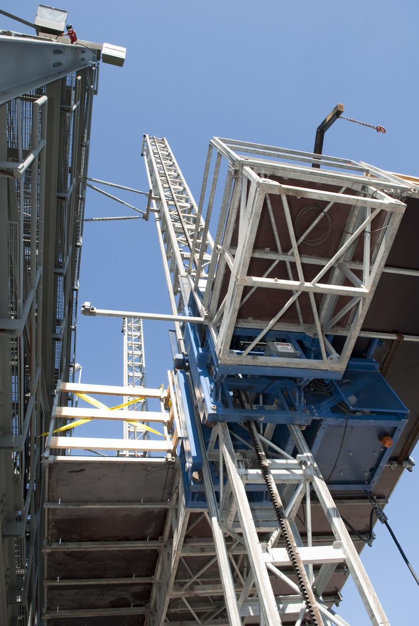
CAPE CANAVERAL, Fla. -- At NASA's Kennedy Space Center in Florida, training takes place atop a mast climber that is attached to launch simulation towers outside the Launch Equipment Test Facility. The training includes attaching carrier plates, water and air systems, and electricity to the climber to simulate working in Kennedy's Vehicle Assembly Building (VAB). Mast climbers can be substituted for fixed service structures currently inside the VAB to provide access to any type of launch vehicle. Since 1977, the facility has supported NASA’s Launch Services, shuttle, International Space Station, and Constellation programs, as well as commercial providers. Last year, the facility underwent a major upgrade to support even more programs, projects and customers. It houses a 6,000-square-foot high bay, cable fabrication and molding shop, pneumatics shop, machine and weld shop and full-scale control room. Outside, the facility features a water flow test loop, vehicle motion simulator and a cryogenic system. Photo credit: NASA/Jim Grossmann
CAPE CANAVERAL, Fla. -- At NASA's Kennedy Space Center in Florida, testing of the Tilt-Up Umbilical Arm (TUUA) prototype's Environmental Control System Quick Disconnect takes place in the Launch Equipment Test Facility's 6,000-square-foot high bay. The prototype is used to demonstrate the safe disconnect and retraction of ground umbilical plates and associated hardware of a launch vehicle's upper stage and service module. The Environmental Control System consists of regulated air, which would be used to purge an inner tank and crew module. Since 1977, the facility has supported NASA’s Launch Services, shuttle, International Space Station, and Constellation programs, as well as commercial providers. The facility recently underwent a major upgrade to support even more programs, projects and customers. It houses a cable fabrication and molding shop, pneumatics shop, machine and weld shop and full-scale control room. Outside, the facility features a water flow test loop, vehicle motion simulator, 600-ton test fixture, launch simulation towers and a cryogenic system. Photo credit: NASA/Jack Pfaller
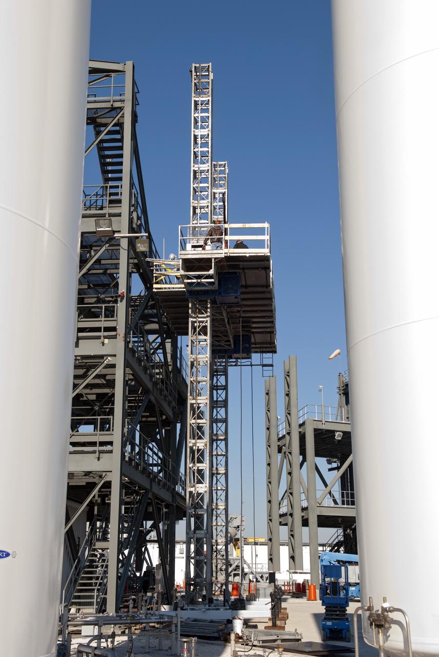
CAPE CANAVERAL, Fla. -- At NASA's Kennedy Space Center in Florida, workers receive training atop a mast climber that is attached to launch simulation towers outside the Launch Equipment Test Facility. The training includes attaching carrier plates, water and air systems, and electricity to the climber to simulate working in Kennedy's Vehicle Assembly Building (VAB). Mast climbers can be substituted for fixed service structures currently inside the VAB to provide access to any type of launch vehicle. Since 1977, the facility has supported NASA’s Launch Services, shuttle, International Space Station, and Constellation programs, as well as commercial providers. Last year, the facility underwent a major upgrade to support even more programs, projects and customers. It houses a 6,000-square-foot high bay, cable fabrication and molding shop, pneumatics shop, machine and weld shop and full-scale control room. Outside, the facility features a water flow test loop, vehicle motion simulator and a cryogenic system. Photo credit: NASA/Jim Grossmann
CAPE CANAVERAL, Fla. -- At NASA's Kennedy Space Center in Florida, workers receive training on a mast climber that is attached to launch simulation towers outside the Launch Equipment Test Facility. The training includes attaching carrier plates, water and air systems, and electricity to the climber to simulate working in Kennedy's Vehicle Assembly Building (VAB). Mast climbers can be substituted for fixed service structures currently inside the VAB to provide access to any type of launch vehicle. Since 1977, the facility has supported NASA’s Launch Services, shuttle, International Space Station, and Constellation programs, as well as commercial providers. Last year, the facility underwent a major upgrade to support even more programs, projects and customers. It houses a 6,000-square-foot high bay, cable fabrication and molding shop, pneumatics shop, machine and weld shop and full-scale control room. Outside, the facility features a water flow test loop, vehicle motion simulator and a cryogenic system. Photo credit: NASA/Jim Grossmann
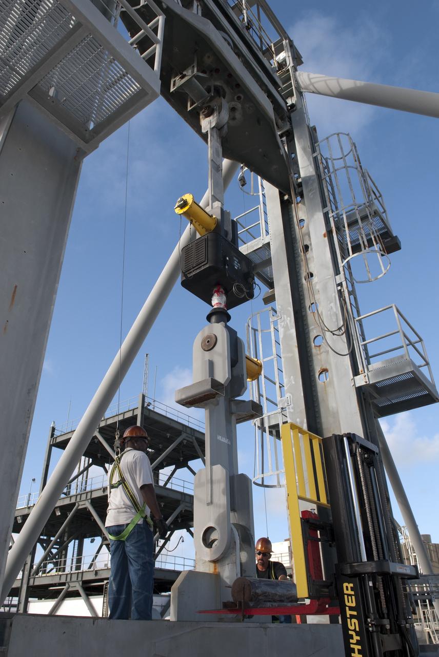
CAPE CANAVERAL, Fla. -- At NASA's Kennedy Space Center in Florida, the 600-Ton Test Fixture outside the Launch Equipment Test Facility conducts a 500,000-pound pull test of a bridge crane lifting element, which is used to lift space shuttles in the Vehicle Assembly Building. The fixture proofload tests, in tension and compression, a variety of ground support equipment, including slings, lifting beams and other critical lifting hardware that require periodic proofloading. Since 1977, the facility has supported NASA’s Launch Services, shuttle, International Space Station, and Constellation programs, as well as commercial providers. The facility recently underwent a major upgrade to support even more programs, projects and customers. It houses a 6,000-square-foot high bay, cable fabrication and molding shop, pneumatics shop, machine and weld shop and full-scale control room. Outside, the facility features a water flow test loop, vehicle motion simulator, launch simulation towers and a cryogenic system. Photo credit: NASA/Jim Grossmann

CAPE CANAVERAL, Fla. -- At NASA's Kennedy Space Center in Florida, the 600-Ton Test Fixture outside the Launch Equipment Test Facility conducts a 500,000-pound pull test of a bridge crane lifting element, which is used to lift space shuttles in the Vehicle Assembly Building. The fixture proofload tests, in tension and compression, a variety of ground support equipment, including slings, lifting beams and other critical lifting hardware that require periodic proofloading. Since 1977, the facility has supported NASA’s Launch Services, shuttle, International Space Station, and Constellation programs, as well as commercial providers. The facility recently underwent a major upgrade to support even more programs, projects and customers. It houses a 6,000-square-foot high bay, cable fabrication and molding shop, pneumatics shop, machine and weld shop and full-scale control room. Outside, the facility features a water flow test loop, vehicle motion simulator, launch simulation towers and a cryogenic system. Photo credit: NASA/Jim Grossmann
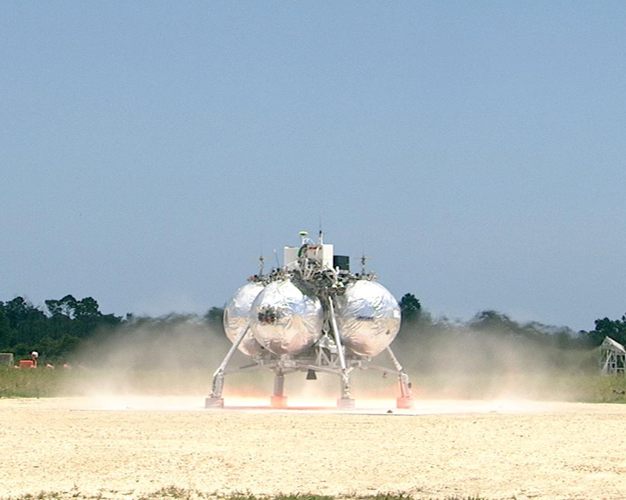
CAPE CANAVERAL, Fla. – At the Shuttle Landing Facility at NASA’s Kennedy Space Center in Florida, the Morpheus prototype lander begins to lift off of the ground during a free-flight test. Testing of the prototype lander had been ongoing at NASA’s Johnson Space Center in Houston in preparation for its first free-flight test at Kennedy Space Center. Morpheus was manufactured and assembled at JSC and Armadillo Aerospace. Morpheus is large enough to carry 1,100 pounds of cargo to the moon – for example, a humanoid robot, a small rover, or a small laboratory to convert moon dust into oxygen. The primary focus of the test is to demonstrate an integrated propulsion and guidance, navigation and control system that can fly a lunar descent profile to exercise the Autonomous Landing and Hazard Avoidance Technology, or ALHAT, safe landing sensors and closed-loop flight control. For more information on Project Morpheus, visit http://morpheuslander.jsc.nasa.gov/. Photo credit: NASA
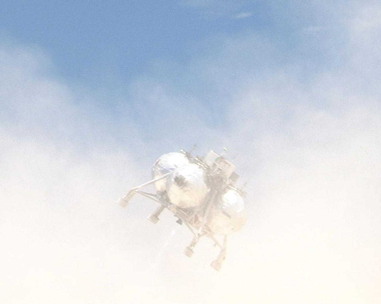
CAPE CANAVERAL, Fla. – During a free-flight test of the Project Morpheus vehicle at the Shuttle Landing Facility at NASA’s Kennedy Space Center in Florida, the vehicle lifted off the ground and then experienced a hardware component failure, which prevented it from maintaining stable flight. Engineers are looking into the test data and the agency will release information as it becomes available. Failures such as these were anticipated prior to the test, and are part of the development process for any complex spaceflight hardware. Testing of the prototype lander had been ongoing at NASA’s Johnson Space Center in Houston in preparation for its first free-flight test at Kennedy Space Center. Morpheus was manufactured and assembled at JSC and Armadillo Aerospace. Morpheus is large enough to carry 1,100 pounds of cargo to the moon – for example, a humanoid robot, a small rover, or a small laboratory to convert moon dust into oxygen. The primary focus of the test is to demonstrate an integrated propulsion and guidance, navigation and control system that can fly a lunar descent profile to exercise the Autonomous Landing and Hazard Avoidance Technology, or ALHAT, safe landing sensors and closed-loop flight control. For more information on Project Morpheus, visit http://morpheuslander.jsc.nasa.gov/. Photo credit: NASA
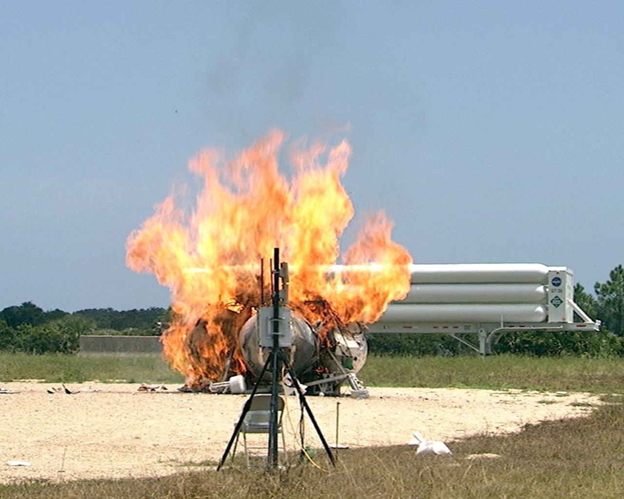
CAPE CANAVERAL, Fla. – During a free-flight test of the Project Morpheus vehicle at the Shuttle Landing Facility at NASA’s Kennedy Space Center in Florida, the vehicle lifted off the ground and then experienced a hardware component failure, which prevented it from maintaining stable flight. No one was injured and the resulting fire was extinguished by Kennedy fire personnel. Engineers are looking into the test data and the agency will release information as it becomes available. Failures such as these were anticipated prior to the test, and are part of the development process for any complex spaceflight hardware. Testing of the prototype lander had been ongoing at NASA’s Johnson Space Center in Houston in preparation for its first free-flight test at Kennedy Space Center. Morpheus was manufactured and assembled at JSC and Armadillo Aerospace. Morpheus is large enough to carry 1,100 pounds of cargo to the moon – for example, a humanoid robot, a small rover, or a small laboratory to convert moon dust into oxygen. The primary focus of the test is to demonstrate an integrated propulsion and guidance, navigation and control system that can fly a lunar descent profile to exercise the Autonomous Landing and Hazard Avoidance Technology, or ALHAT, safe landing sensors and closed-loop flight control. For more information on Project Morpheus, visit http://morpheuslander.jsc.nasa.gov/. Photo credit: NASA
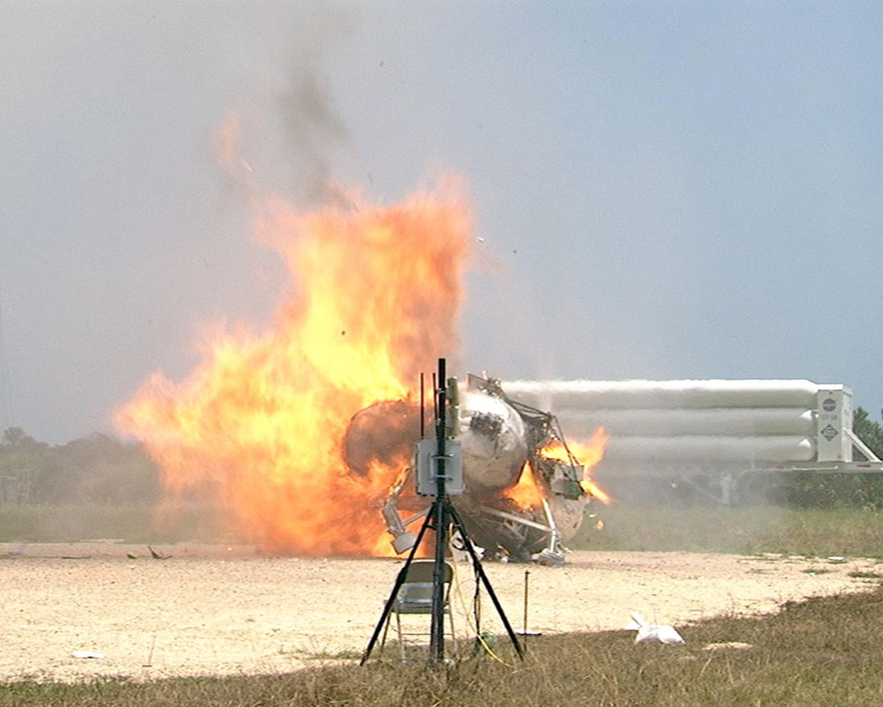
CAPE CANAVERAL, Fla. – During a free-flight test of the Project Morpheus vehicle at the Shuttle Landing Facility at NASA’s Kennedy Space Center in Florida, the vehicle lifted off the ground and then experienced a hardware component failure, which prevented it from maintaining stable flight. No one was injured and the resulting fire was extinguished by Kennedy fire personnel. Engineers are looking into the test data and the agency will release information as it becomes available. Failures such as these were anticipated prior to the test, and are part of the development process for any complex spaceflight hardware. Testing of the prototype lander had been ongoing at NASA’s Johnson Space Center in Houston in preparation for its first free-flight test at Kennedy Space Center. Morpheus was manufactured and assembled at JSC and Armadillo Aerospace. Morpheus is large enough to carry 1,100 pounds of cargo to the moon – for example, a humanoid robot, a small rover, or a small laboratory to convert moon dust into oxygen. The primary focus of the test is to demonstrate an integrated propulsion and guidance, navigation and control system that can fly a lunar descent profile to exercise the Autonomous Landing and Hazard Avoidance Technology, or ALHAT, safe landing sensors and closed-loop flight control. For more information on Project Morpheus, visit http://morpheuslander.jsc.nasa.gov/. Photo credit: NASA

A technician at the National Advisory Committee for Aeronautics (NACA) Lewis Flight Propulsion Laboratory examines one of the massive axial-flow compressor stages that created the high-speed air flow through the 8- by 6-Foot Supersonic Wind Tunnel. The tunnel’s first run was on April 3, 1949, just over a week before this photograph was taken. The 8- by 6 was the laboratory’s first large supersonic wind tunnel and the NACA’s largest supersonic tunnel at the time. The 8- by 6-foot tunnel was originally an open-throat non-return tunnel. The supersonic air flow was blown through the tubular facility and expelled out the other end into the atmosphere with a roar. Complaints from the local community led to the addition of a muffler at the tunnel exit in 1956 and the eventual addition of a return leg. The return leg allowed the tunnel to be operated as either an open system with large doors venting directly to the atmosphere for propulsion system tests or as a closed loop for aerodynamic tests. The air flow was generated by a large seven-stage axial-flow compressor, seen in this photograph, that was powered by three electric motors with a combined 87,000 horsepower. The system required 36,000 kilowatts of power per hour to generate wind velocities of Mach 1.5, and 72,000 kilowatts per hour for Mach 2.0.
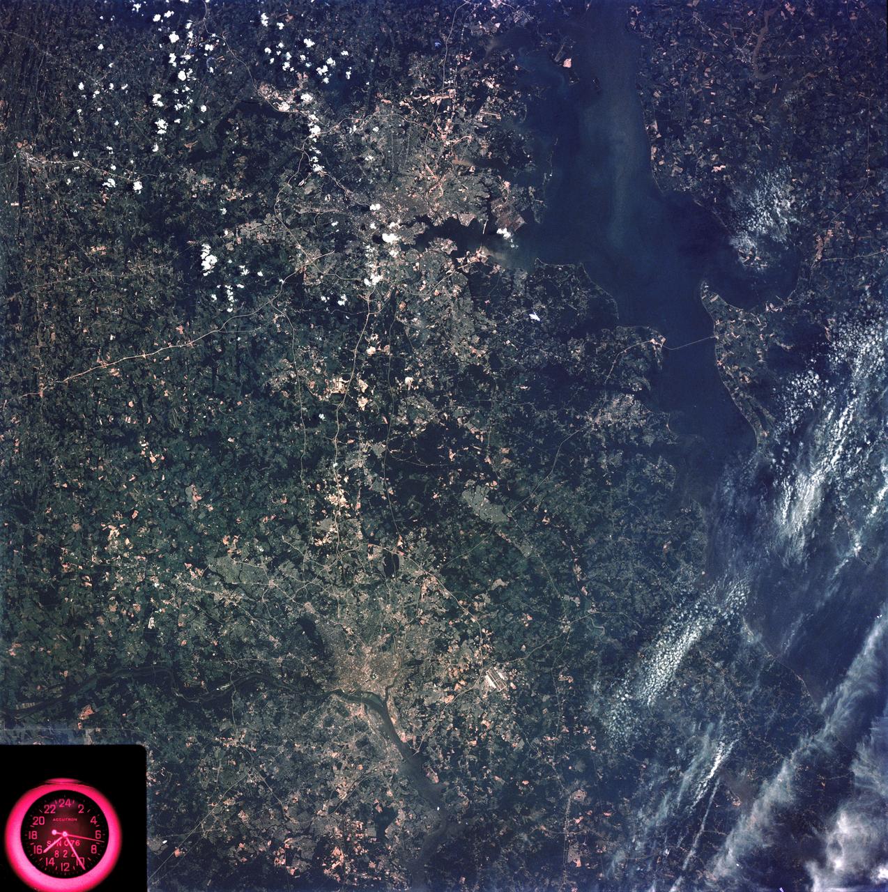
SL3-83-166 (July-September 1973) --- A vertical view of the Washington D.C. and the Baltimore, Maryland area is seen in the Skylab 3 Earth Resources Experiments Package S190-B (five-inch Earth terrain camera) photograph taken from the Skylab space station in Earth orbit. The Chesapeake Bay is on the right (east) side of the picture. The Potomac River flows through the Washington area in the lower left (southwest) corner of the photograph. Several transportation routes and major highways stand out very distinctly. Especially conspicuous are the beltways around the cities, Interstate 95 between Baltimore and the nation?s capitol and Interstate 70N leading west from Baltimore. The tunnel and harbor facilities in Baltimore show clearly, also. Identifiable features in the Washington area include the Capitol Building, the Mall area, Robert F. Kennedy Stadium (white circle), the five bridges across the Potomac, Andrews Air Force Base (on east loop), and the smaller Anacostia River. The extent of the urbanization in this area is dramatically illustrated in this picture. The photograph has sufficient resolution that the housing patterns for individual suburban areas are clearly defined with the houses shown as pink gray, wooded areas as dark green and cleared areas light green. Chesapeake Bay circulation patterns are indicated by contrast of dark and light blue. Sediment plumes (red) are seen entering the bay north and east of Baltimore. The bay bridge stands out white against the blue water. The detailed information contained in this one photograph will be of direct use to several EREP investigator teams in land use analysis, sedimentation and circulation patterns in the bay, and resource surveys of Maryland. All EREP photography is available to the public through the Department of Interior?s Earth Resources Observations Systems Data Center, Sioux Falls, South Dakota, 57198. Photo credit: NASA

This radar image shows the Star City cosmonaut training center, east of Moscow, Russia. Four American astronauts are training here for future long-duration flights aboard the Russian Mir space station. These joint flights are giving NASA and the Russian Space Agency experience necessary for the construction of the international Alpha space station, beginning in late 1997. This image was acquired by the Spaceborne Imaging Radar-C/X-band Synthetic Aperture Radar (SIR-C/X-SAR), on its 62nd orbit on October 3, 1994. This Star City image is centered at 55.55 degrees north latitude and 38.0 degrees east longitude. The area shown is approximately 32 kilometers by 49 kilometers (20 miles by 30 miles). North is to the top in this image. The radar illumination is from the top of the image. The image was produced using three channels of SIR-C radar data: red indicates L-band (23 cm wavelength, horizontally transmitted and received); green indicates L-band (horizontally transmitted and vertically received); blue indicates C-band (6 cm wavelength, horizontally transmitted and vertically received). In general, dark pink areas are agricultural; pink and light blue areas are urban communities; black areas represent lakes and rivers; dark blue areas are cleared forest; and light green areas are forested. The prominent black runways just right of center are Shchelkovo Airfield, about 4 km long. The textured pale blue-green area east and southeast of Shchelkovo Airfield is forest. Just east of the runways is a thin railroad line running southeast; the Star City compound lies just east of the small bend in the rail line. Star City contains the living quarters and training facilities for Russian cosmonauts and their families. Moscow's inner loop road is visible at the lower left edge of the image. The Kremlin is just off the left edge, on the banks of the meandering Moskva River. The Klyazma River snakes to the southeast from the reservoir in the upper left (shown in bright red), passing just east of Star City and flowing off the lower right edge of the image. The dark blue band of the Vorya River runs north-south in the upper right quadrant, east of Star City. http://photojournal.jpl.nasa.gov/catalog/PIA01775