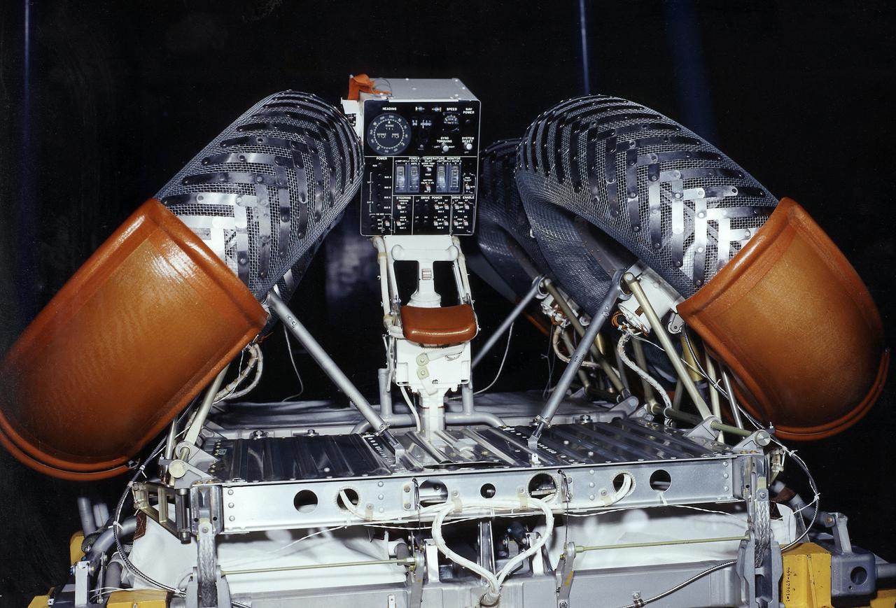
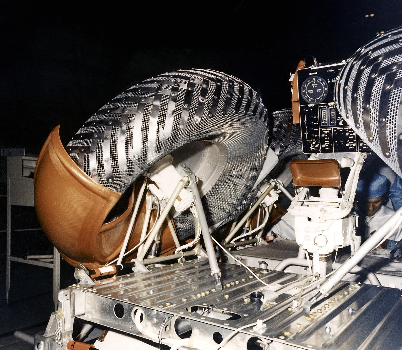
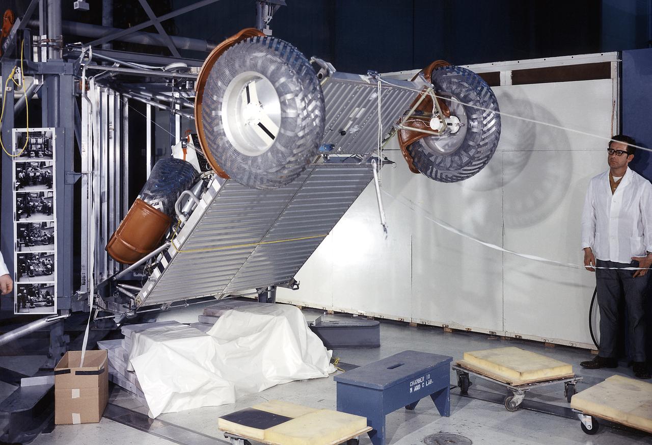
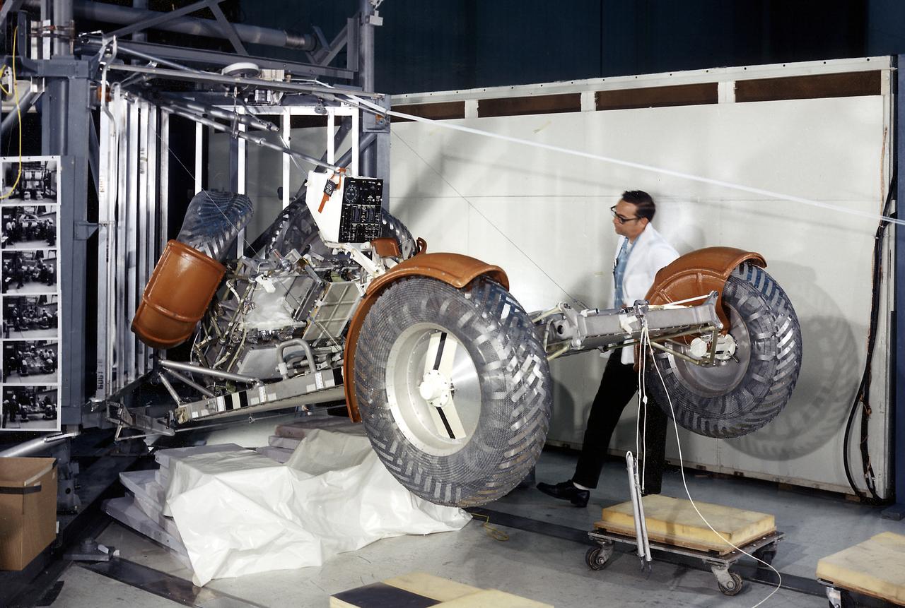
This photograph shows a rear view of a folded configuration of the Lunar Roving Vehicle (LRV) No. 2. The LRV was built to give Apollo astronauts a greater range of mobility during lunar exploration. It was an open-space and collapsible vehicle about 10 feet long with large mesh wheels, anterna, appendages, tool caddies, and camera. An LRV was used on each of the last three Apollo missions; Apollo 15, Apollo 16, and Apollo 17. It was built by the Boeing Company under the direction of the Marshall Space Flight Center.
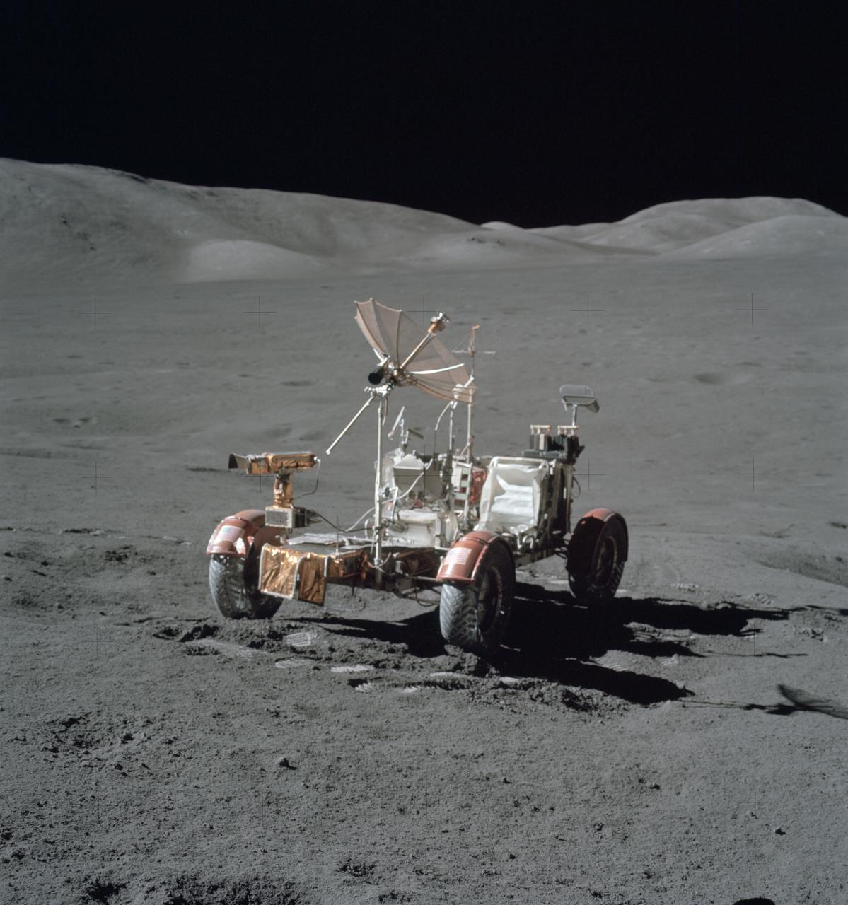
The Lunar Roving Vehicle (LRV) was designed to transport astronauts and materials on the Moon. An LRV was used on each of the last three Apollo missions, Apollo 15, Apollo 16, and Apollo 17, in 1971 and 1972 to permit the crew to travel several miles from the lunar landing site. This photograph was taken during the Apollo 15 mission.
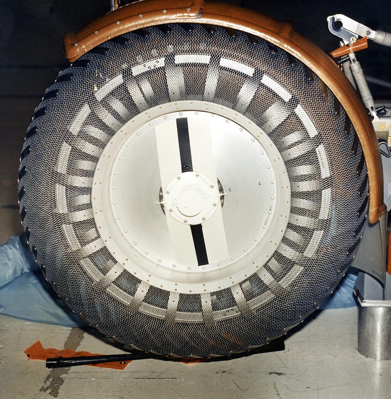
This is a close-up view of a left front wheel of the Lunar Roving Vehicle (LRV) No. 1. The LRV was built to give Apollo astronauts a greater range of mobility during lunar exploration. It was an open-space and collapsible vehicle about 10 feet long with large mesh wheels, anterna, appendages, tool caddies, and camera. An LRV was used on each of the last three Apollo missions; Apollo 15, Apollo 16, and Apollo 17. It was built by the Boeing Company under the direction of the Marshall Space Flight Center.
This is a close-up inboard view of a left front wheel of the Lunar Roving Vehicle (LRV) No. 1. The LRV was built to give Apollo astronauts a greater Range of mobility during lunar exploration. It was an open-space and collapsible vehicle about 10 feet long with large mesh wheels, anterna, appendages, tool caddies, and camera. An LRV was used on each of the last three Apollo missions; Apollo 15, Apollo 16, and Apollo 17. It was built by the Boeing Company under the direction of the Marshall Space Flight Center.
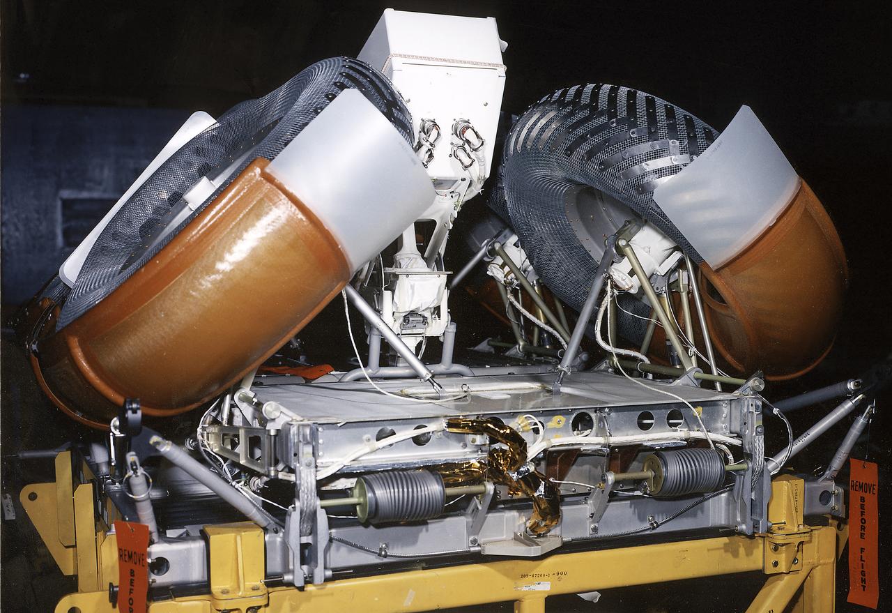
This photograph shows a front view of a folded configuration of the Lunar Roving Vehicle (LRV) No. 2. The LRV was built to give Apollo astronauts a greater range of mobility during lunar exploration. It was an open-space and collapsible vehicle about 10 feet long with large mesh wheels, anterna, appendages, tool caddies, and camera. An LRV was used on each of the last three Apollo missions; Apollo 15, Apollo 16, and Apollo 17. It was built by the Boeing Company under the direction of the Marshall Space Flight Center.

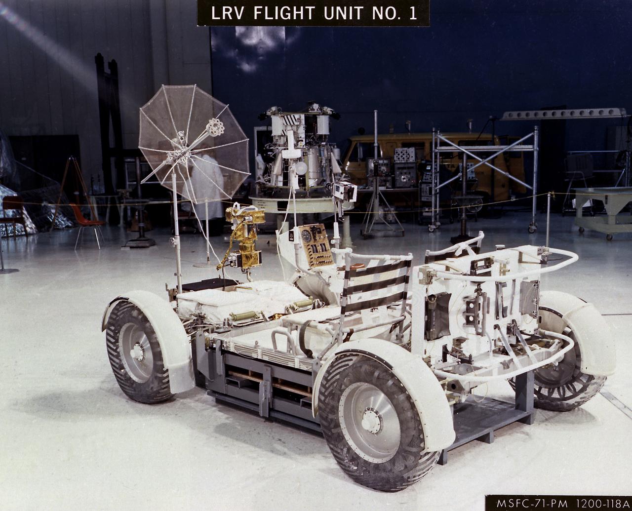
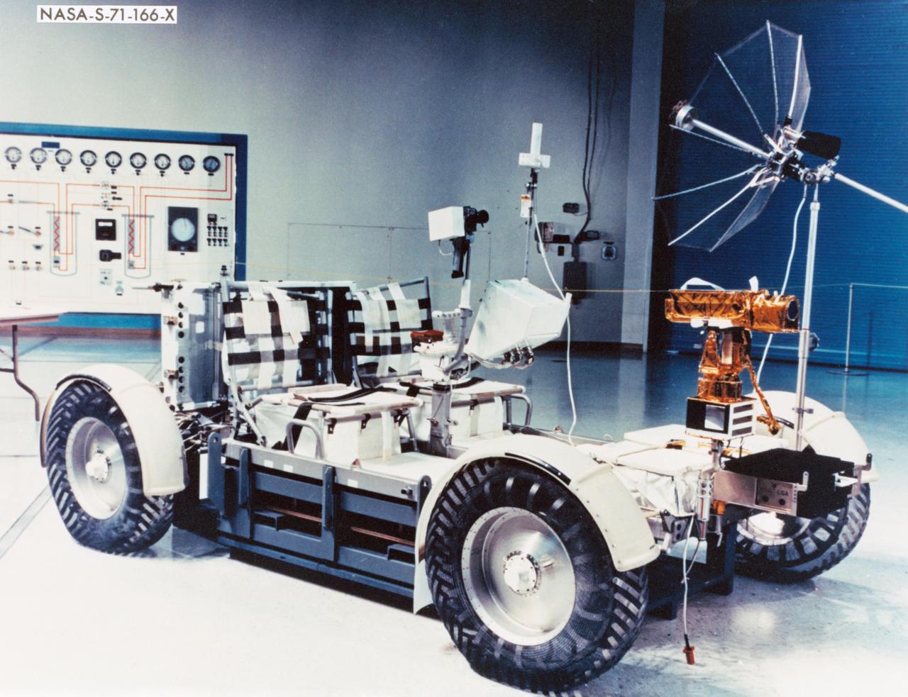
The Lunar Roving Vehicle (LRV) was designed to transport astronauts and materials on the Moon. It was a collapsible open-space vehicle about 10 feet long with large mesh wheels, anterna, appendages, tool caddies, and cameras. Powered by two 36-volt batteries, it has four 1/4-hp drive motors, one for each wheel. The vehicle was designed to travel in forward or reverse, negotiate obstacles about 1 foot high, cross crevasses about 2 feet wide, and climb or descend moderate slopes. Its speed limit was about 9 miles (14 kilometers) per hour. An LRV was used on each of the last three Apollo missions (Apollo 15, Apollo 16, and Apollo 17) and permitted the crew to travel several miles from the Lunar Module. The LRV was designed, developed, and tested by the Marshall Space Flight Center, and built by the Boeing Plant in Kent, Washington.
The Lunar Roving Vehicle (LRV) was designed to transport astronauts and materials on the Moon. It was a collapsible open-space vehicle about 10 feet long with large mesh wheels, anterna, appendages, tool caddies, and cameras. Powered by two 36-volt batteries, it has four 1/4-hp drive motors, one for each wheel. The vehicle was designed to travel in forward or reverse, negotiate obstacles about 1 foot high, cross crevasses about 2 feet wide, and climb or descend moderate slopes. Its speed limit was about 9 miles (14 kilometers) per hour. An LRV was used on each of the last three Apollo missions (Apollo 15, Apollo 16, and Apollo 17) and permitted the crews to travel several miles from the Lunar Module. The LRV was designed, developed, and tested by the Marshall Space Flight Center, and built by the Boeing Plant in Kent, Washington.
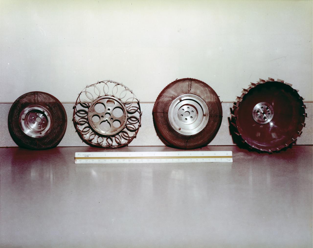
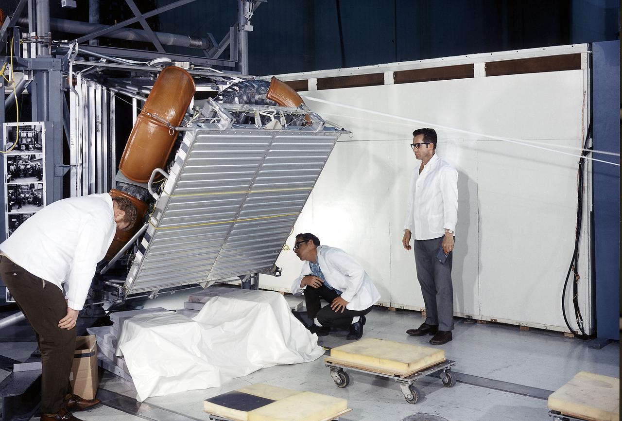
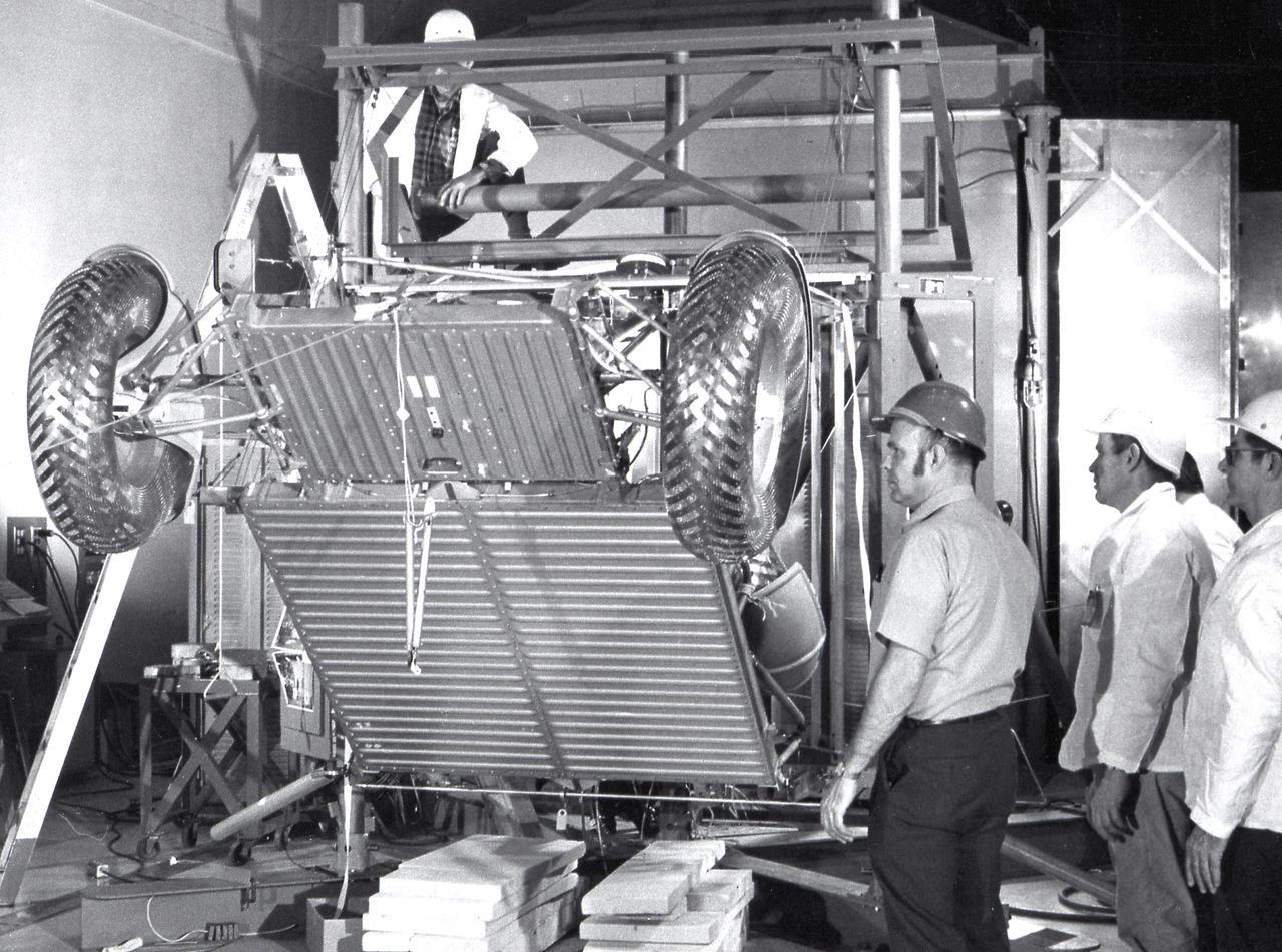
Under the direction of Marshall Space Flight Center (MSFC), the Lunar Roving Vehicle (LRV) was designed to allow Apollo astronauts a greater range of mobility during lunar exploration missions. During the development process, LRV prototype wheels underwent soil tests in building 4481 at Marshall Space Flight Center (MSFC). Pictured from left to right are the wheels for: LRV, Bendix Corporation, Local Scientific Survey Module (LSSM), and Grumman Industries.
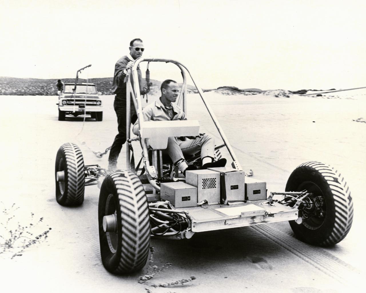
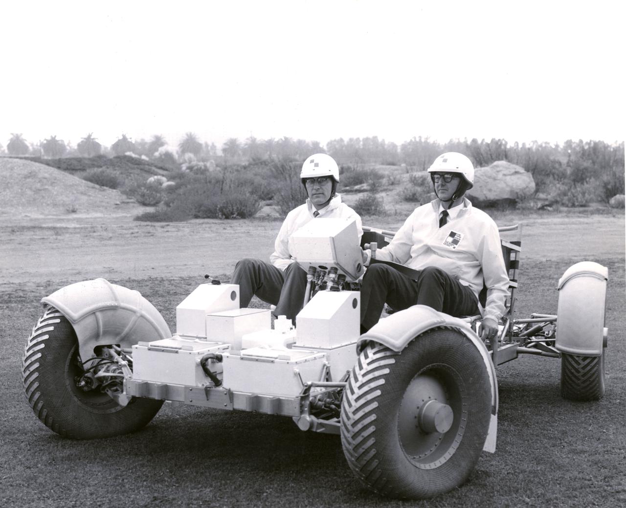
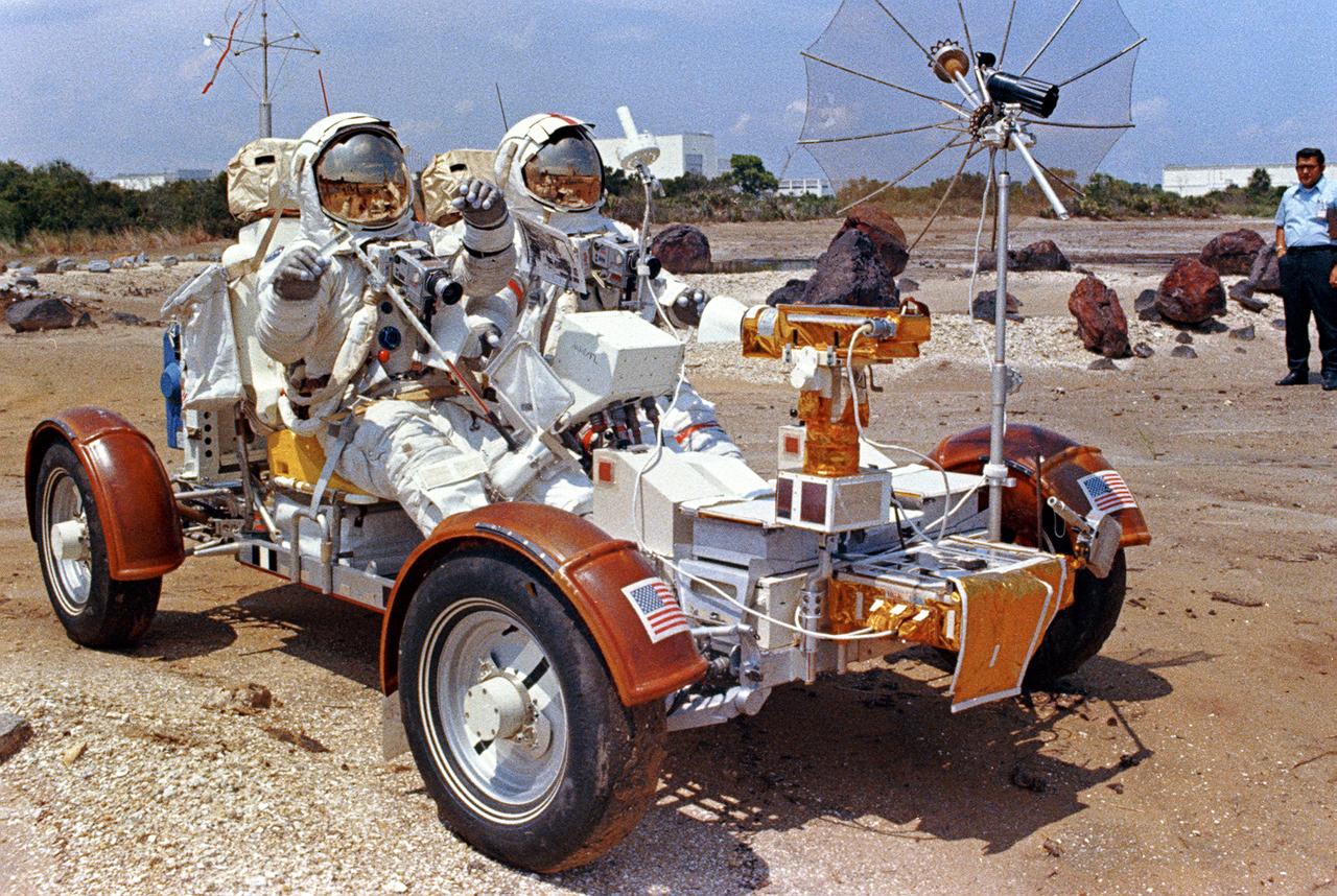
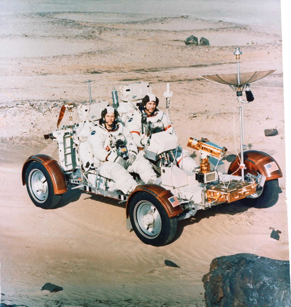
Astronauts Jack Lousma (seated) and Gerald Carr tested the Lunar Roving Vehicle (LRV) training unit on the sands near Pismo Beach. The vehicle was built by the AC Delco electronics division of General Motors Corporation. Under the direction of Marshall Space Flight Center (MSFC), the LRV was designed to allow Apollo astronauts a greater range of mobility during lunar exploration missions. The LRVs were deployed during the last three Apollo missions; Apollo 15, Apollo 16, and Apollo 17.
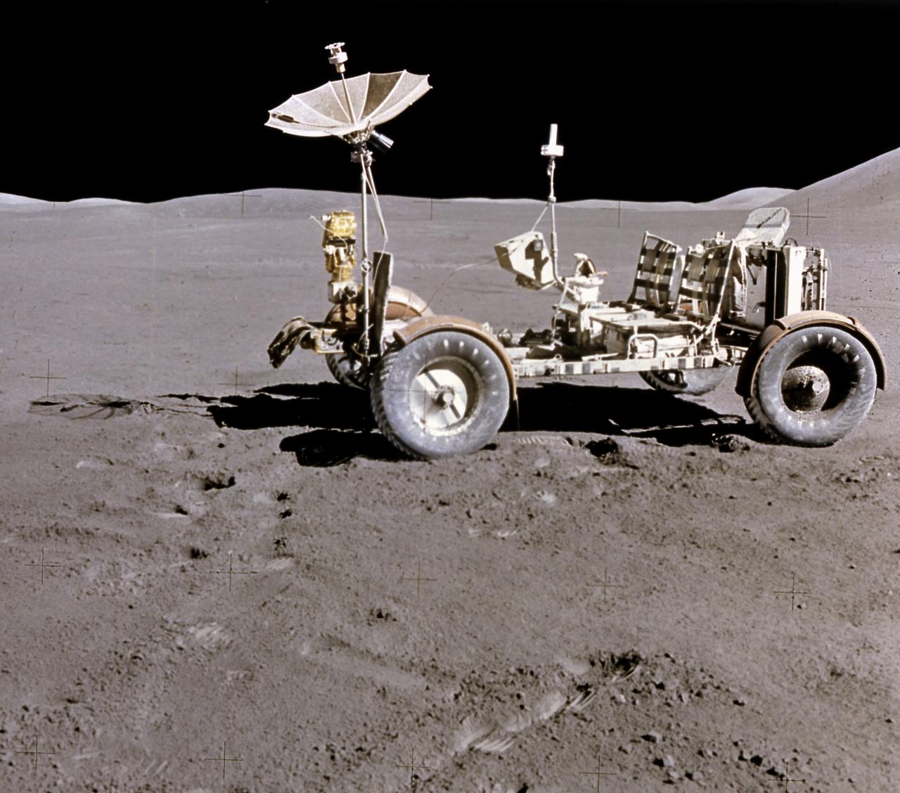
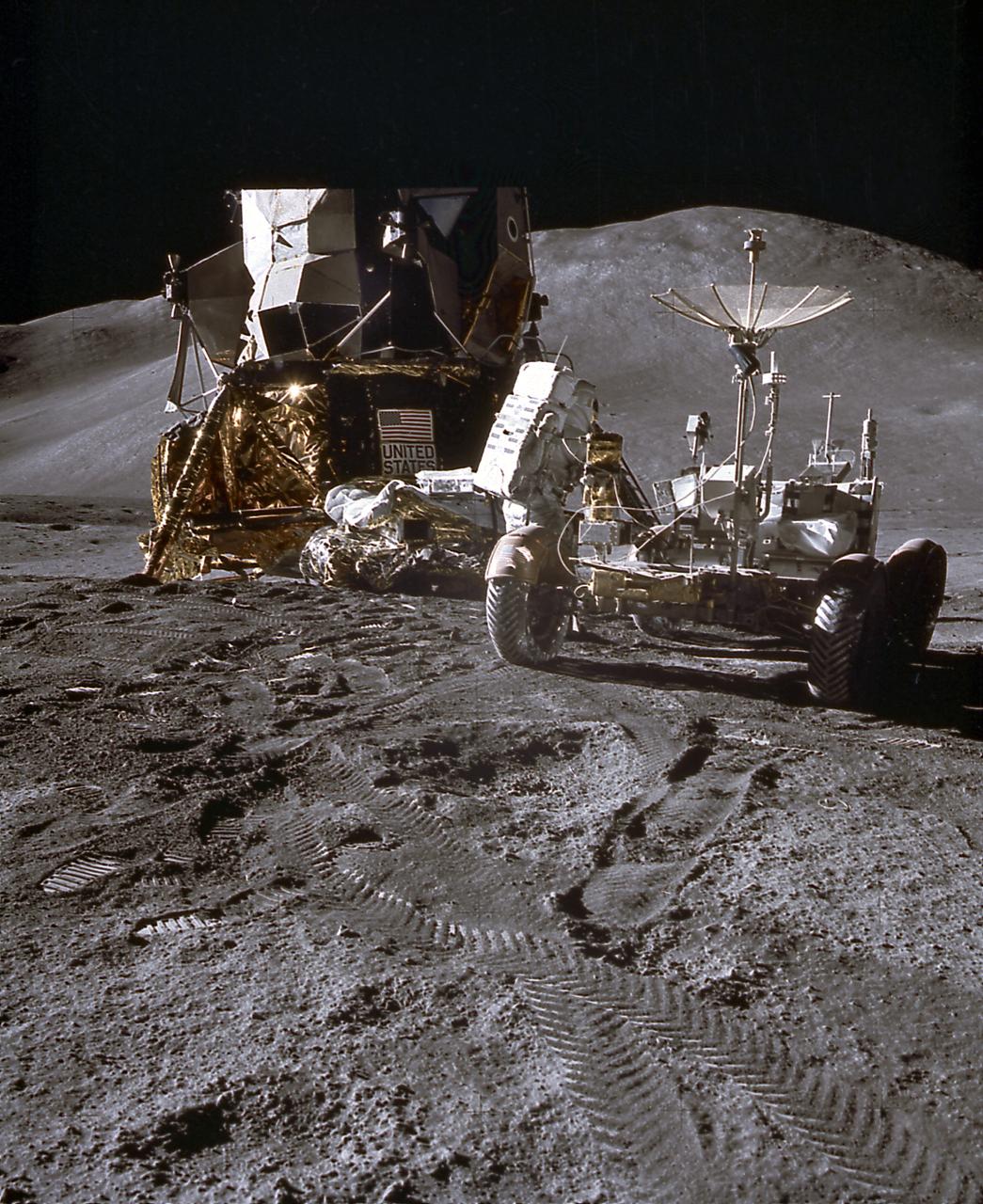
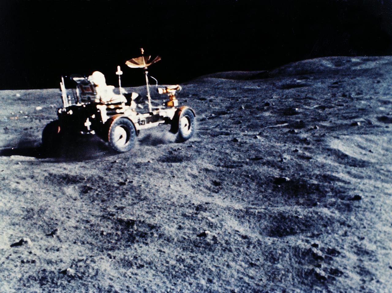
This photograph of the Lunar Roving Vehicle (LRV) was taken during the Apollo 15 mission. Powered by battery, the lightweight electric car greatly increased the range of mobility and productivity on the scientific traverses for astronauts. It weighed 462 pounds (77 pounds on the Moon) and could carry two suited astronauts, their gear and cameras, and several hundred pounds of bagged samples. The LRV's mobility was quite high. It could climb and descend slopes of about 25 degrees. The LRV was designed and developed by the Marshall Space Flight Center and built by the Boeing Company.
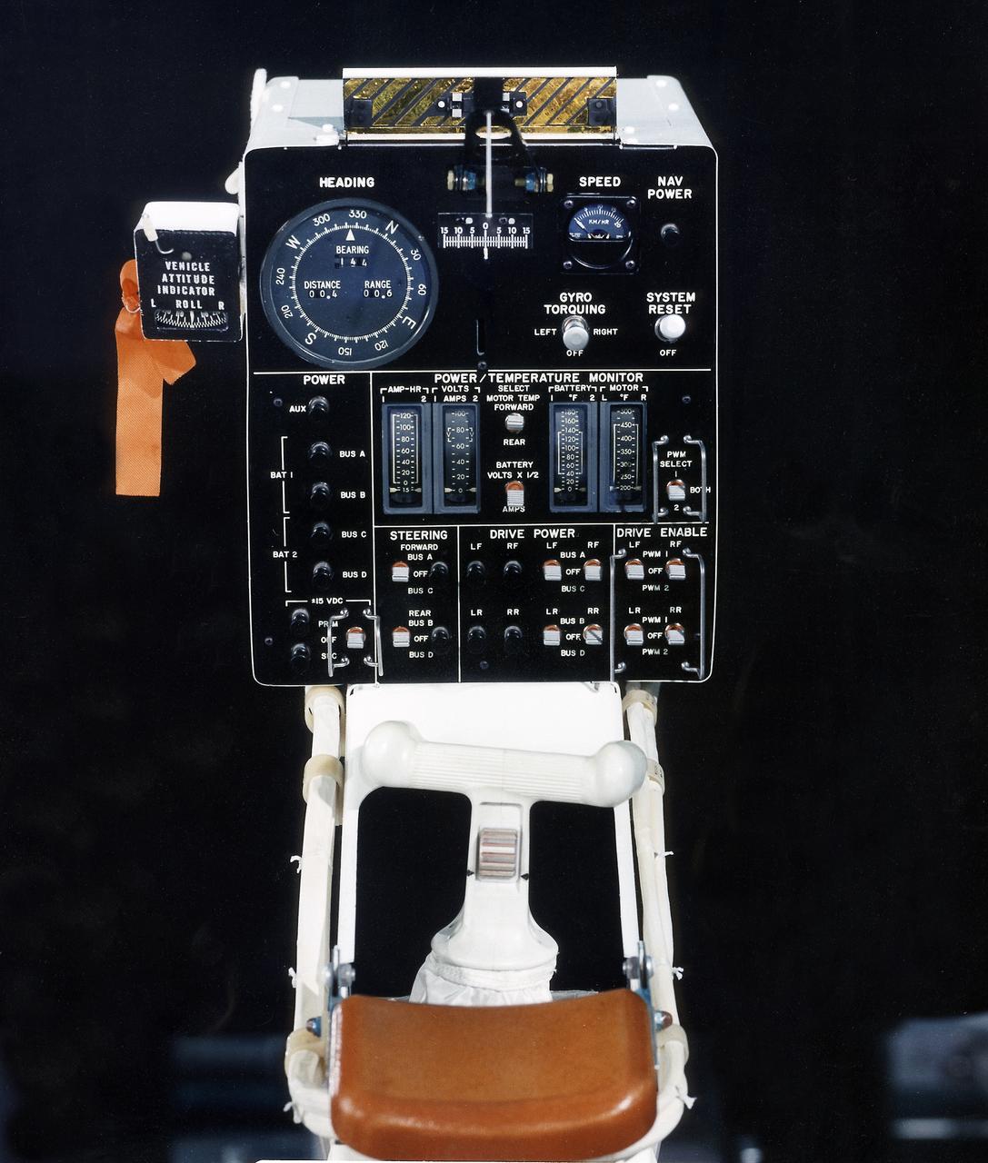
This photograph is a view of a display, control console, and hand controller for the Lunar Roving Vehicle (LRV) No. 2. The LRV was built to give Apollo astronauts a greater range of mobility during lunar exploration. It was an open-space and collapsible vehicle about 10 feet long with large mesh wheels, anterna, appendages, tool caddies, and camera. An LRV was used on each of the last three Apollo missions; Apollo 15, Apollo 16, and Apollo 17. It was built by the Boeing Company under the direction of the Marshall Space Flight Center.
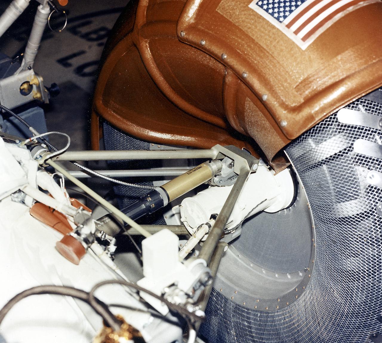
This is a close-up view of a right rear wheel strut of the Lunar Roving Vehicle (LRV) No. 1. The LRV was built to give Apollo astronauts a greater range of mobility during lunar exploration. It was an open-space and collapsible vehicle about 10 feet long with large mesh wheels, anterna, appendages, tool caddies, and camera. An LRV was used on each of the last three Apollo missions; Apollo 15, Apollo 16, and Apollo 17. It was built by the Boeing Company under the direction of the Marshall Space Flight Center.
Delco engineers are operating this Lunar Roving Vehicle (LRV) Trainer. Built by by Delco Electronics Division of the General Motors Corporation, the trainer was shipped to NASA’s Manned Spacecraft Center in Houston, Texas for an astronaut training program. Under the direction of Marshall Space Flight Center (MSFC), the LRV was designed to allow Apollo astronauts a greater range of mobility during lunar exploration missions. The LRVs were deployed during the last three Apollo missions; Apollo 15, Apollo 16, and Apollo 17.
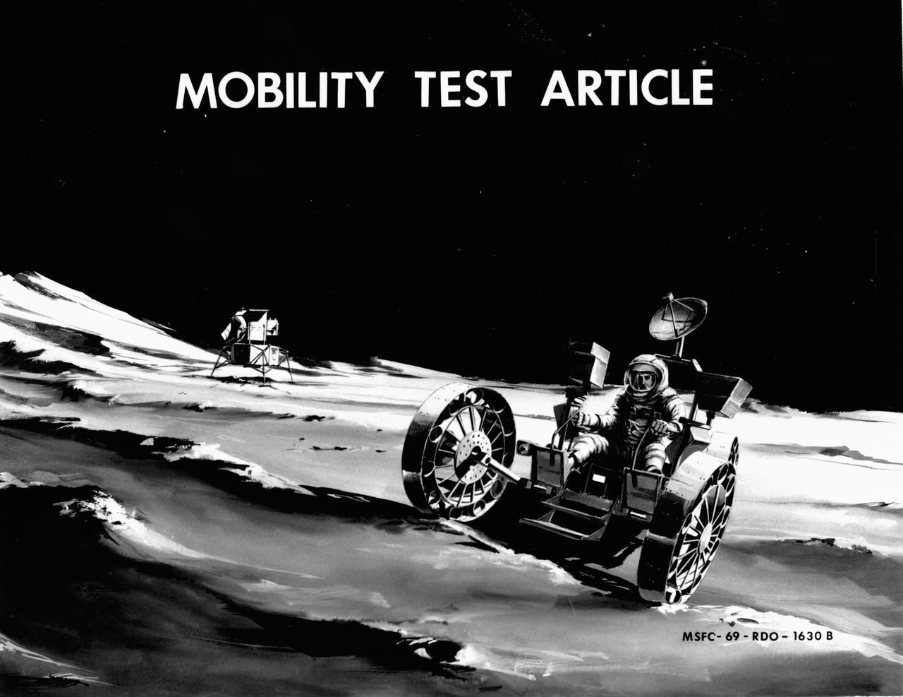
Artist’s concept of a Lunar Roving Vehicle (LRV) Mobility Test Article (MTA) on the Lunar surface. The data provided by the MTA helped in designing the LRV, developed under the direction of MSFC. The LRV was designed to allow Apollo astronauts a greater range of mobility during lunar exploration missions.
A concept of a possible Lunar Roving Vehicle (LRV) built for NASA’s Marshall Space Flight Center (MSFC). This Mobility Test Article (MTA) is one of many that provided data contributing to the design of the LRV, developed under the direction of MSFC. The LRV was designed to allow Apollo astronauts a greater range of mobility during lunar exploration missions.
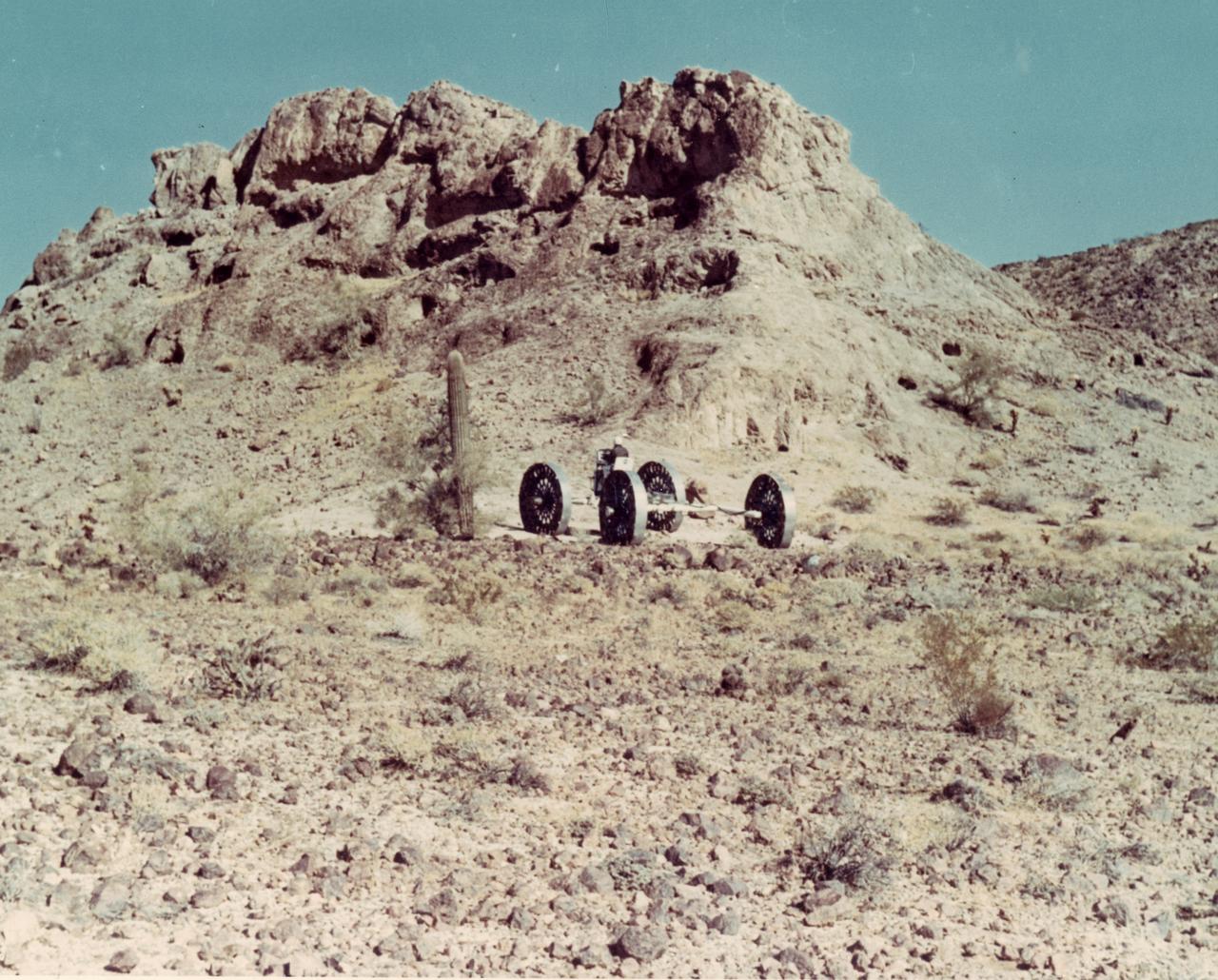
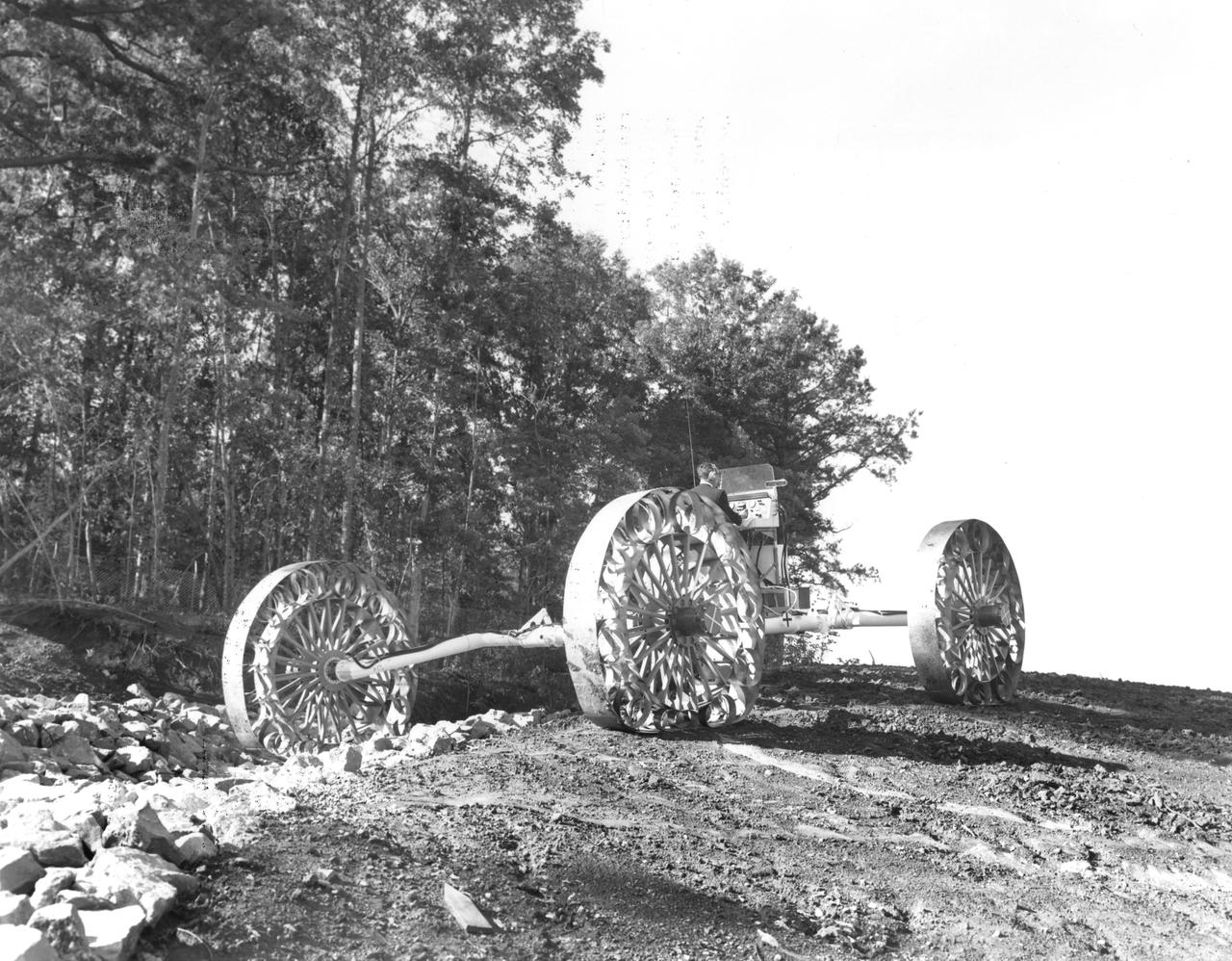
A test engineer drives a Mobility Test Article (MTA) during a test of a Lunar Roving Vehicle (LRV) concept through the mountains of Arizona. The data provided by the MTA helped in designing the LRV, developed under the direction of MSFC. The LRV was designed to allow Apollo astronauts a greater range of mobility during lunar exploration missions.
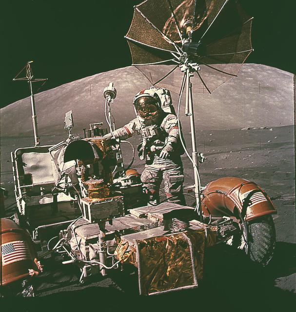
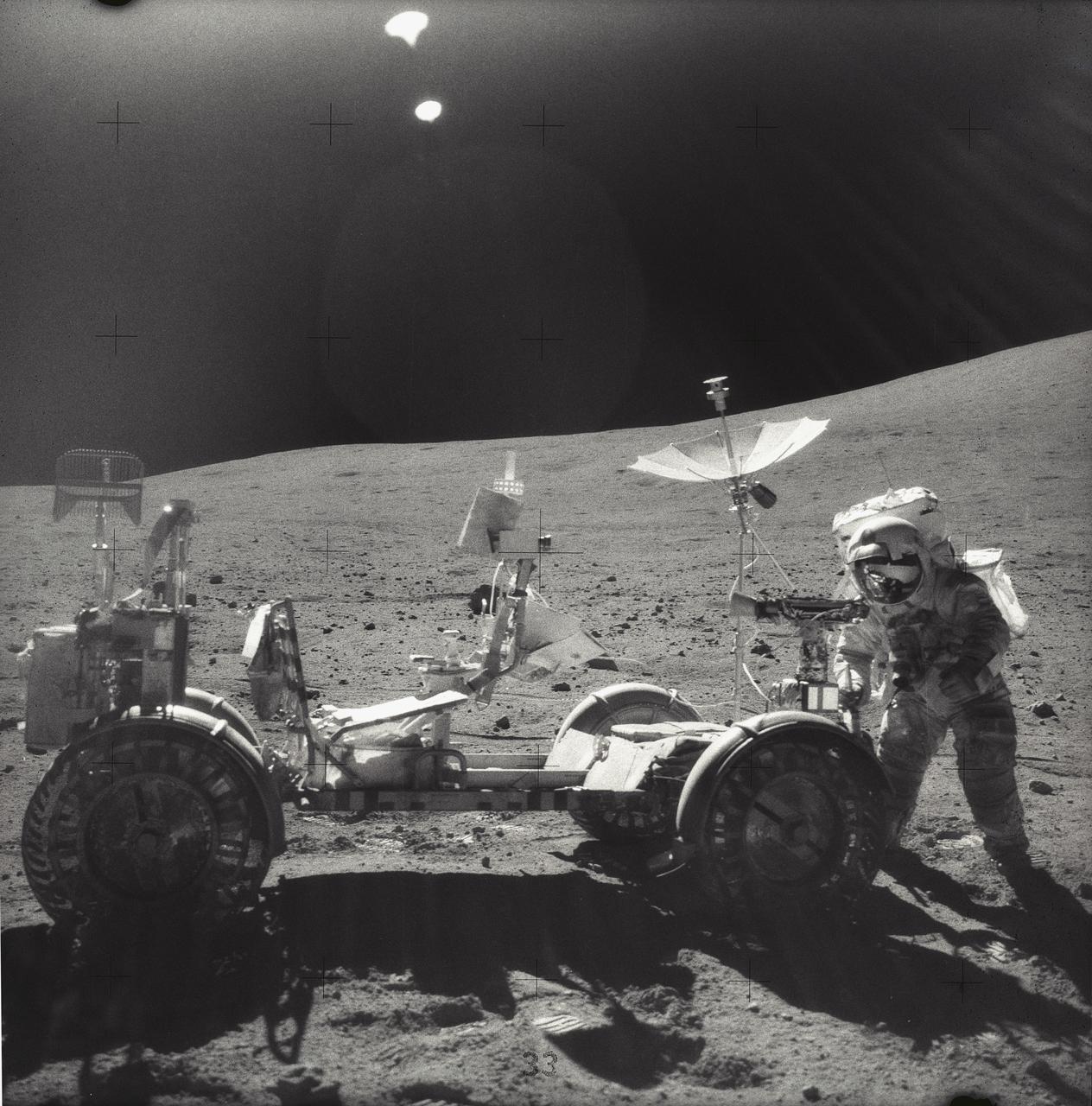
This photograph of an astronaut getting the Lunar Roving Vehicle (LRV) ready for exploration of the lunar surface was taken during activities of the Apollo 15 mission. Designed and developed by the Marshall Space Flight Center and built by the Boeing Company, the LRV was first used on the Apollo 15 mission and increased the range of astronauts' mobility and productivity on the lunar surface.
The Lunar Roving Vehicle (LRV) was designed to transport astronauts and materials on the Moon. An LRV was used on each of the last three Apollo missions; Apollo 15, Apollo 16, and Apollo 17, in 1971 and 1972, to permit the crew to travel several miles from the lunar landing site. This photograph was taken during the Apollo 16 mission.
This photograph was taken during a deployment simulation of the Lunar Roving Vehicle (LRV). The LRV was built to give Apollo astronauts a greater range of mobility during the last three lunar exploration missions; Apollo 15, Apollo 16, and Apollo 17. It was designed and developed by the Marshall Space Flight Center and built by the Boeing Company.
This photograph was taken during a deployment simulation of the Lunar Roving Vehicle (LRV). The LRV was built to give Apollo astronauts a greater range of mobility during the last three lunar exploration missions; Apollo 15, Apollo 16, and Apollo 17. It was designed and developed by the Marshall Space Flight Center and built by the Boeing Company.

This photograph was taken during a deployment simulation of the Lunar Roving Vehicle (LRV). The LRV was built to give Apollo astronauts a greater range of mobility during the last three lunar exploration missions; Apollo 15, Apollo 16, and Apollo 17. It was designed and developed by the Marshall Space Flight Center and built by the Boeing Company.

This in an aerial view (looking north) of a Lunar Roving Vehicle (LRV), often referrd to as “Moonbuggy”, simulator area built at the Marshall Space Flight Center (MSFC) where tesing was performed. The LRV was developed under the direction of MSFC to provide astronauts with greater mobility on the lunar surface.
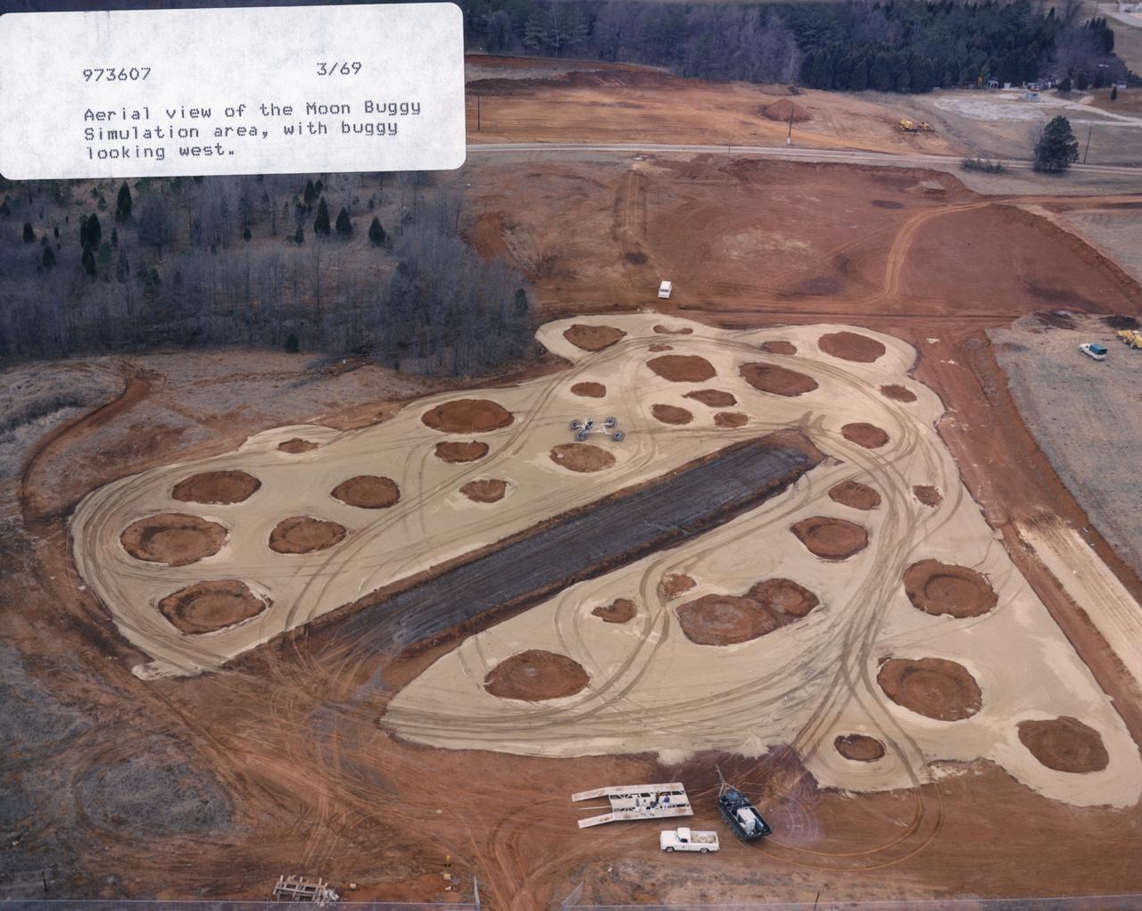
This in an aerial view (looking west) of a Lunar Roving Vehicle (LRV), often referred to as “Moonbuggy”, simulator area built at the Marshall Space Flight Center (MSFC) where tesing was performed. The LRV was developed under the direction of MSFC to provide astronauts with greater mobility on the lunar surface.
This photograph was taken during a deployment simulation of the Lunar Roving Vehicle (LRV). The LRV was built to give Apollo astronauts a greater range of mobility during the last three lunar exploration missions; Apollo 15, Apollo 16, and Apollo 17. It was designed and developed by the Marshall Space Flight Center and built by the Boeing Company.
This photograph shows workmen at the Boeing plant in Kent, Washington, performing deployment tests on the Lunar Roving Vehicle (LRV). The LRV, developed under the direction of the Marshall Space Flight Center, was designed to allow Apollo astronauts a greater range of mobility on the lunar surface during the last three lunar exploration missions; Apollo 15, Apollo 16, and Apollo 17.
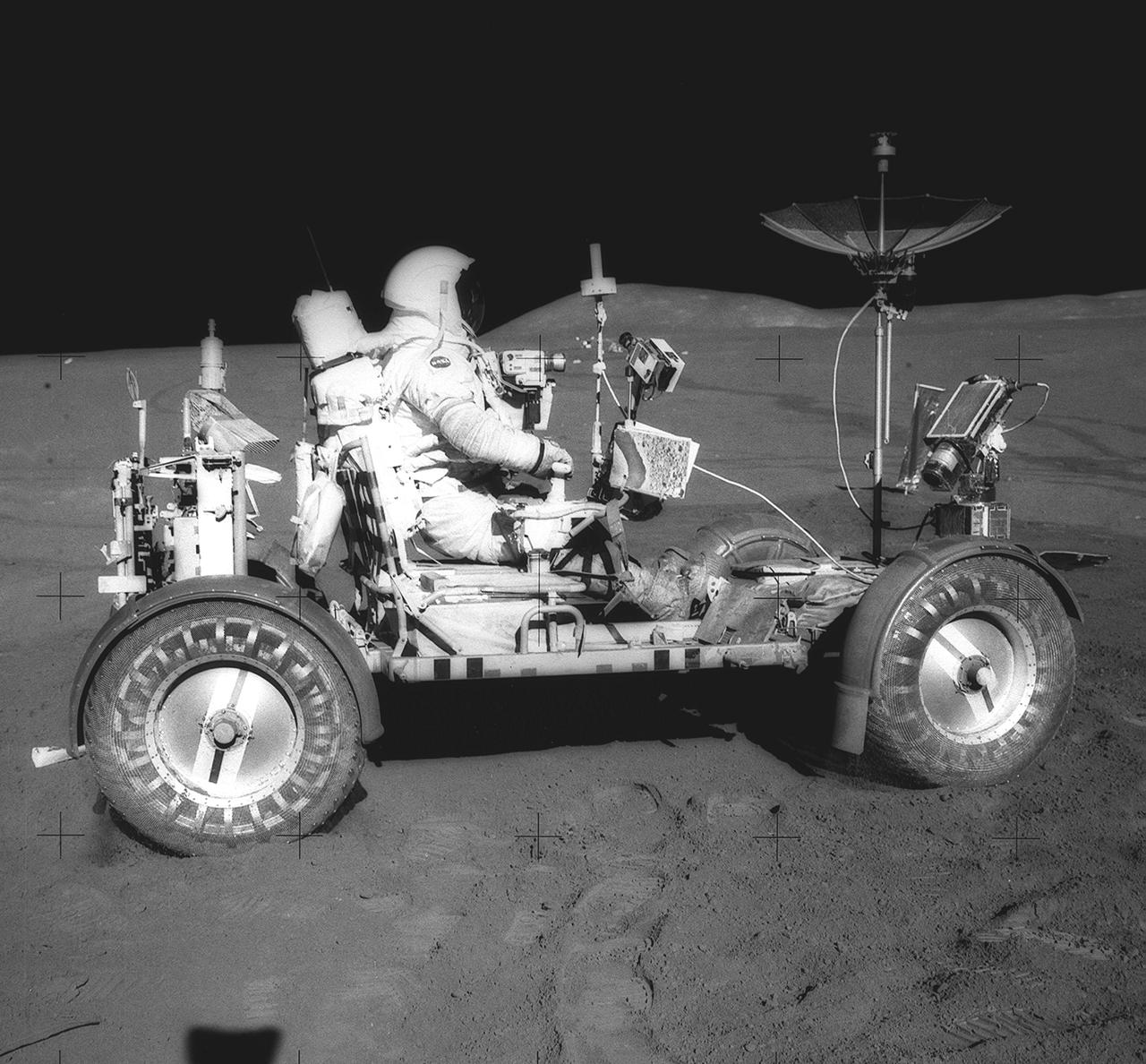
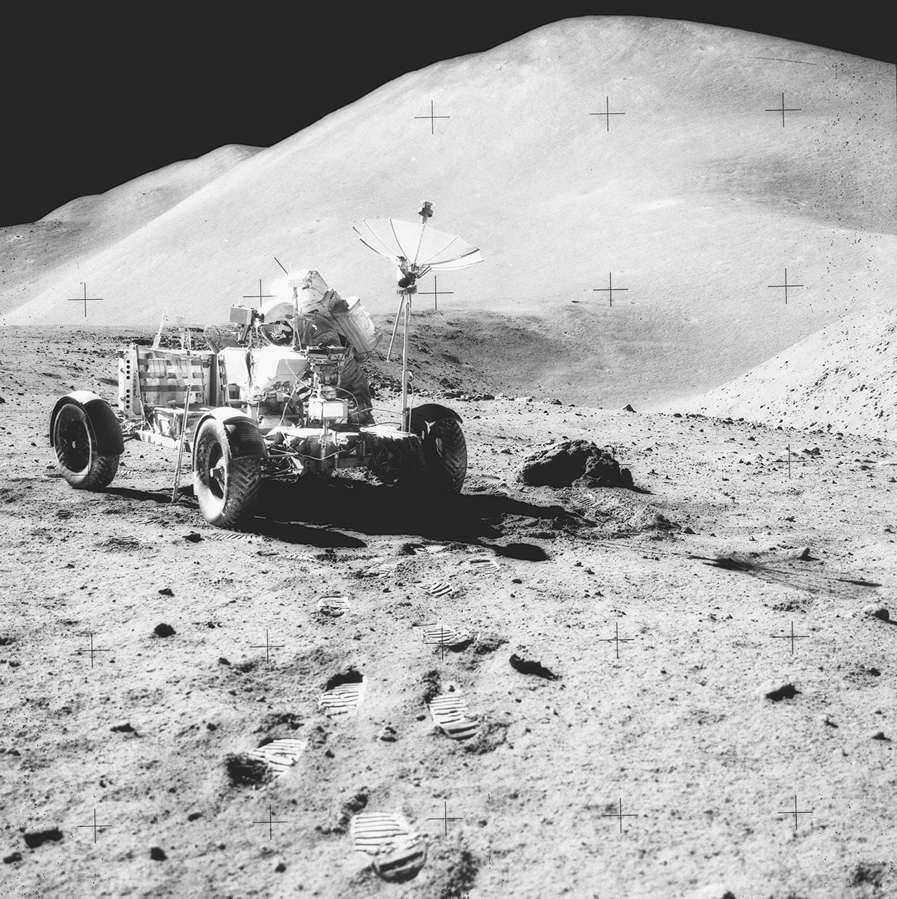
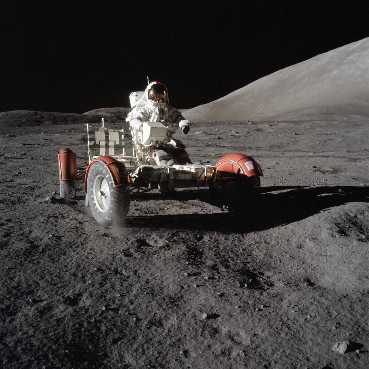
This photograph was taken during the Apollo 15 mission on the lunar surface. Astronaut David R. Scott waits in the Lunar Roving Vehicle (LRV) for astronaut James Irwin for the return trip to the Lunar Module, Falcon, with rocks and soil collected near the Hadley-Apernine landing site. The Apollo 15 was the first mission to use the LRV. Powered by battery, the lightweight electric car greatly increased the range of mobility and productivity on the scientific traverses for astronauts. It weighed 462 pounds (77 pounds on the Moon) and could carry two suited astronauts, their gear and cameras, and several hundred pounds of bagged samples. The LRV's mobility was quite high. It could climb and descend slopes of about 25 degrees. The LRV was designed and developed by the Marshall Space Flight Center and built by the Boeing Company.
This photograph taken during the Apollo 17 mission (the last mission of the Apollo Program), depicts stiff plasticized maps being taped together and fastened by clamps to patch a broken fender of the Lunar Roving Vehicle (LRV). Powered by battery, the lightweight electric car greatly increased the range of mobility and productivity on the scientific traverses for astronauts. It weighed 462 pounds (77 pounds on the Moon) and could carry two suited astronauts, their gear and cameras, and several hundred pounds of bagged samples. The LRV's mobility was quite high. It could climb and descend slopes of about 25 degrees. The LRV was designed and developed by the Marshall Space Flight Center and built by the Boeing Company.
This is an Apollo 17 onboard photo of an astronaut beside the Lunar Roving Vehicle (LRV) on the lunar surface. Designed and developed by the Marshall Space Flight Center and built by the Boeing Company, the LRV was first used on the Apollo 15 mission and increased the range of astronauts' mobility and productivity on the lunar surface. This lightweight electric car had battery power sufficient for about 55 miles. It weighed 462 pounds (77 pounds on the Moon) and could carry two suited astronauts, their gear, cameras, and several hundred pounds of bagged samples. The LRV's mobility was quite high. It could climb and descend slopes of about 25 degrees.
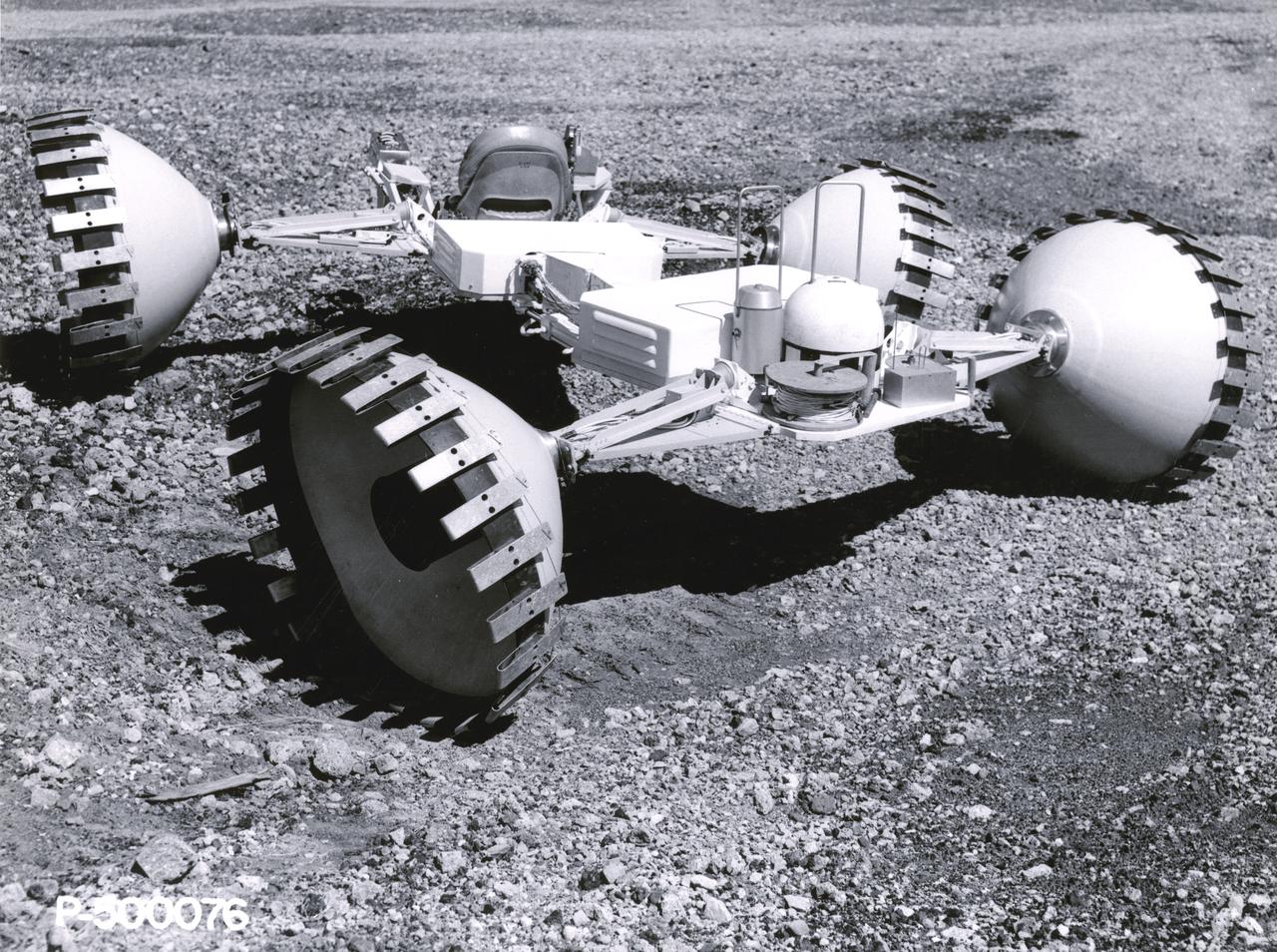
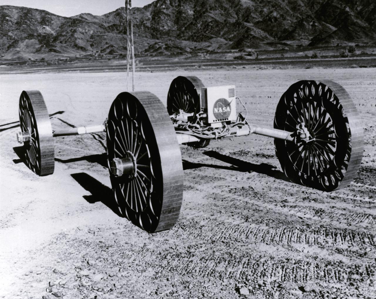
An engineer demonstrates a Mobility Test Article (MTA) at NASA’s Marshall Space Flight Center (MSFC). This unit, weighing 1/6th as much as an actual vehicle, was built by the Bendix Corporation and was one of the concepts of a possible Lunar Roving Vehicle (LRV). The data provided by the MTA helped in designing the Lunar Roving Vehicle (LRV), developed under the direction of MSFC. The LRV was designed to allow Apollo astronauts a greater range of mobility during lunar exploration missions.
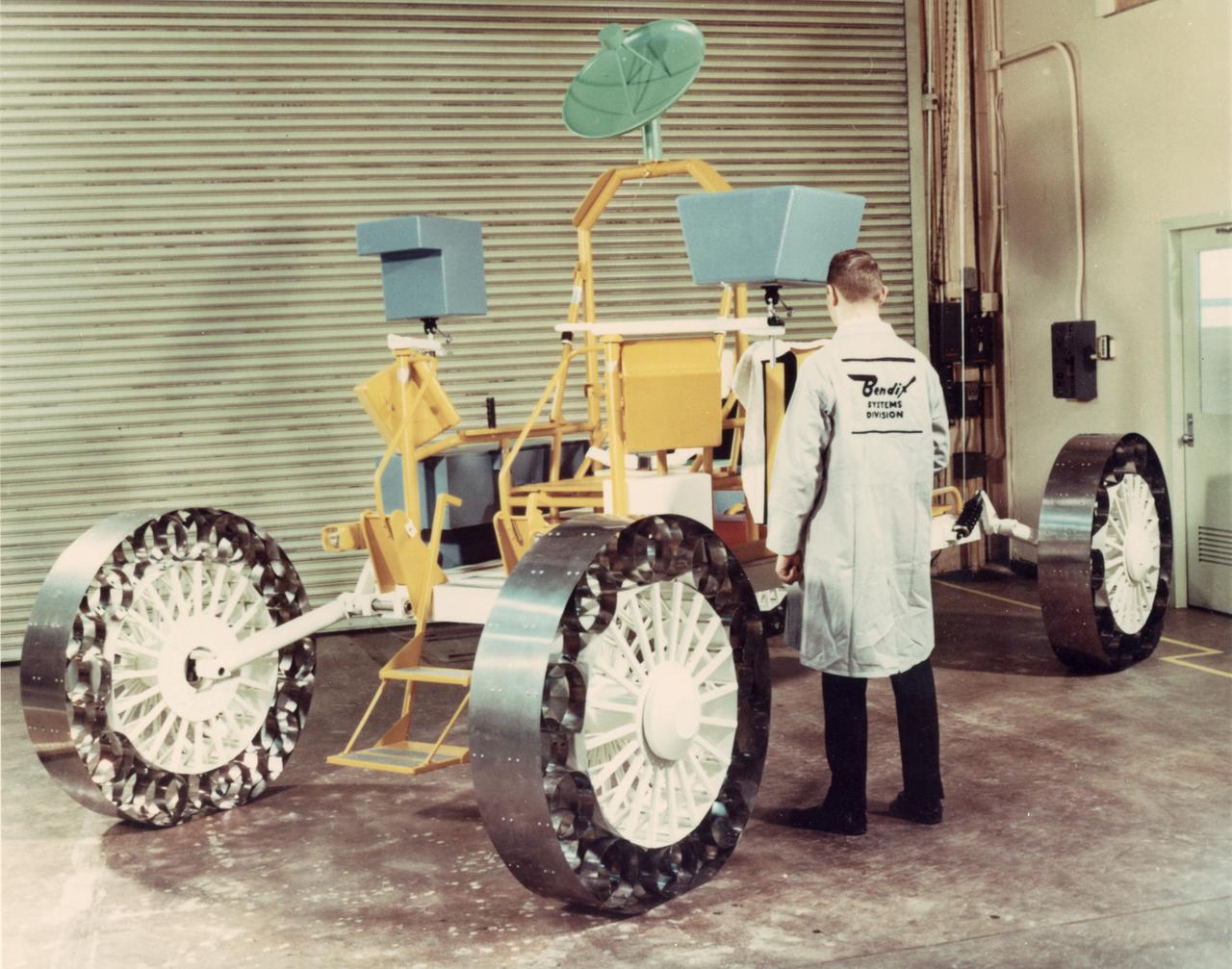
A concept of a possible Lunar Roving Vehicle (LRV) built by the Bendix Corporation for NASA’s Marshall Space Flight Center (MSFC). This Mobility Test Article (MTA) is being inspected by a Bendix technician. The data provided by the MTA helped in designing the LRV, developed under the direction of MSFC. The LRV was designed to allow Apollo astronauts a greater range of mobility during lunar exploration missions.
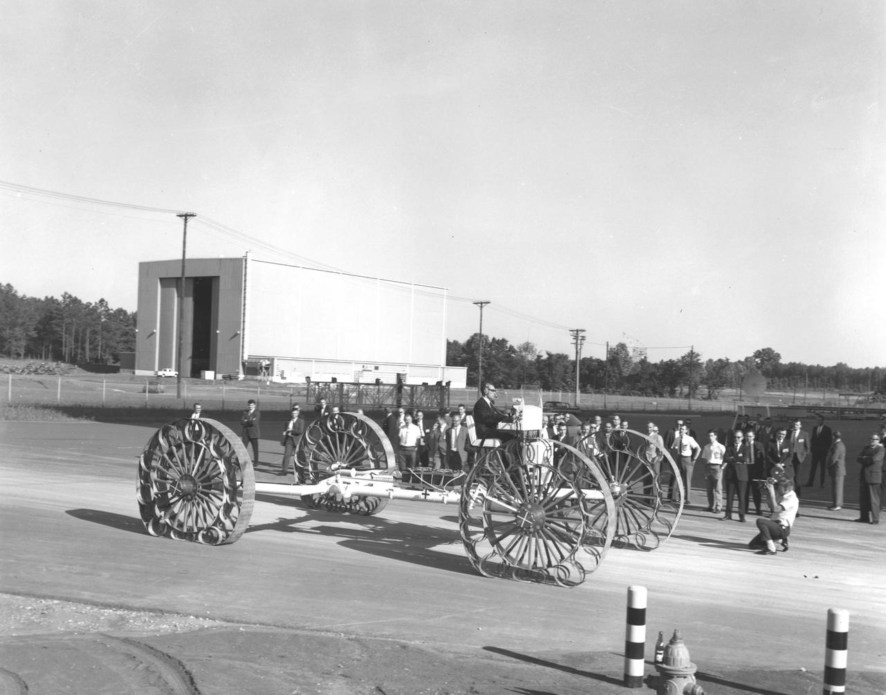
Newsmen watch a test engineer drive a Mobility Test Article (MTA) demonstrated at NASA’s Marshall Space Flight Center (MSFC). This unit, built by the Bendix Corporation, was one of the concepts of a possible Lunar Roving Vehicle (LRV). The data provided by the MTA helped in designing the LRV, developed under the direction of MSFC. The LRV was designed to allow Apollo astronauts a greater range of mobility during lunar exploration missions.
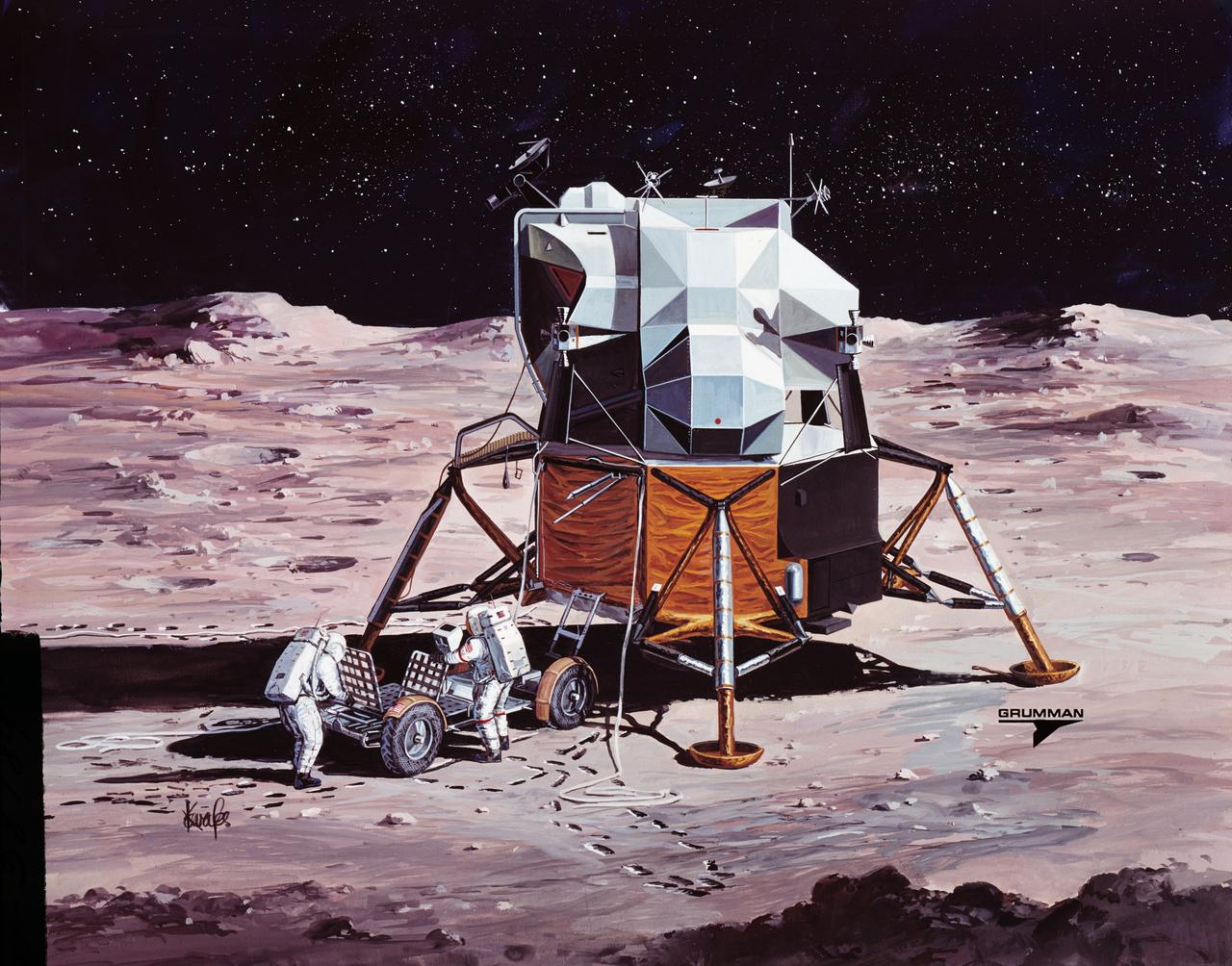
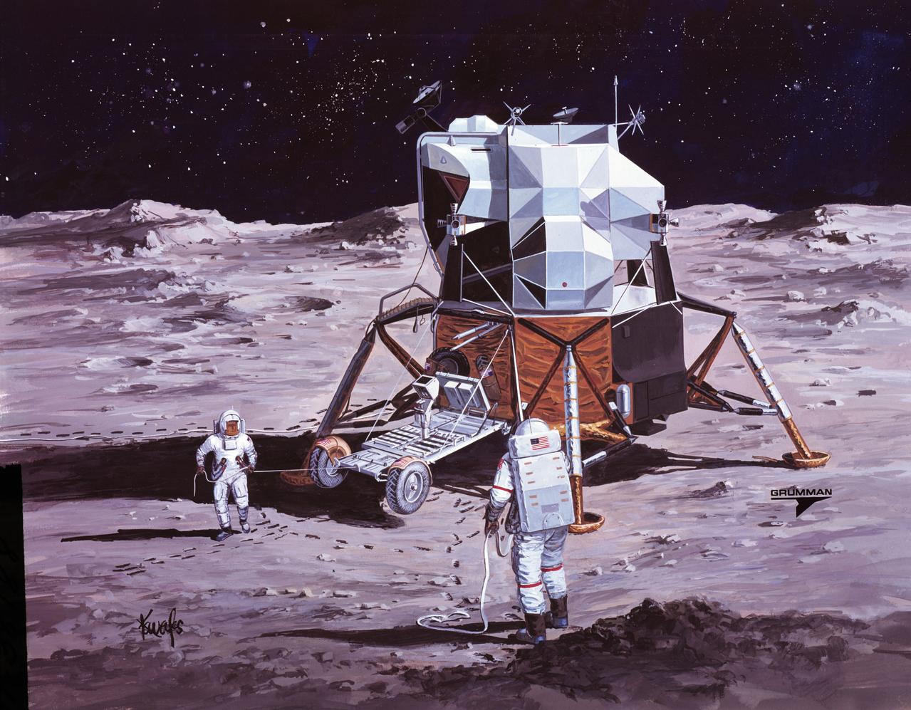
A concept of a possible Lunar Roving Vehicle (LRV) built by the Grumman Industries for NASA’s Marshall Space Flight Center (MSFC), this Mobility Test Article (MTA) is undergoing a full fledged test, complete with space suit attire. The data provided by the MTA helped in designing the LRV, developed under the direction of MSFC. The LRV was designed to allow Apollo astronauts a greater range of mobility during lunar exploration missions.
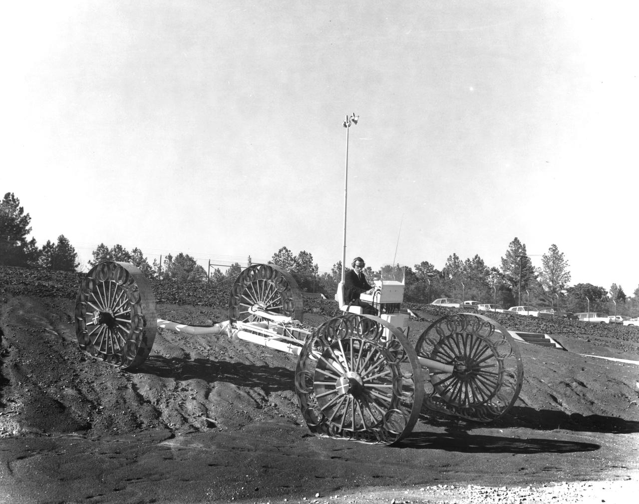
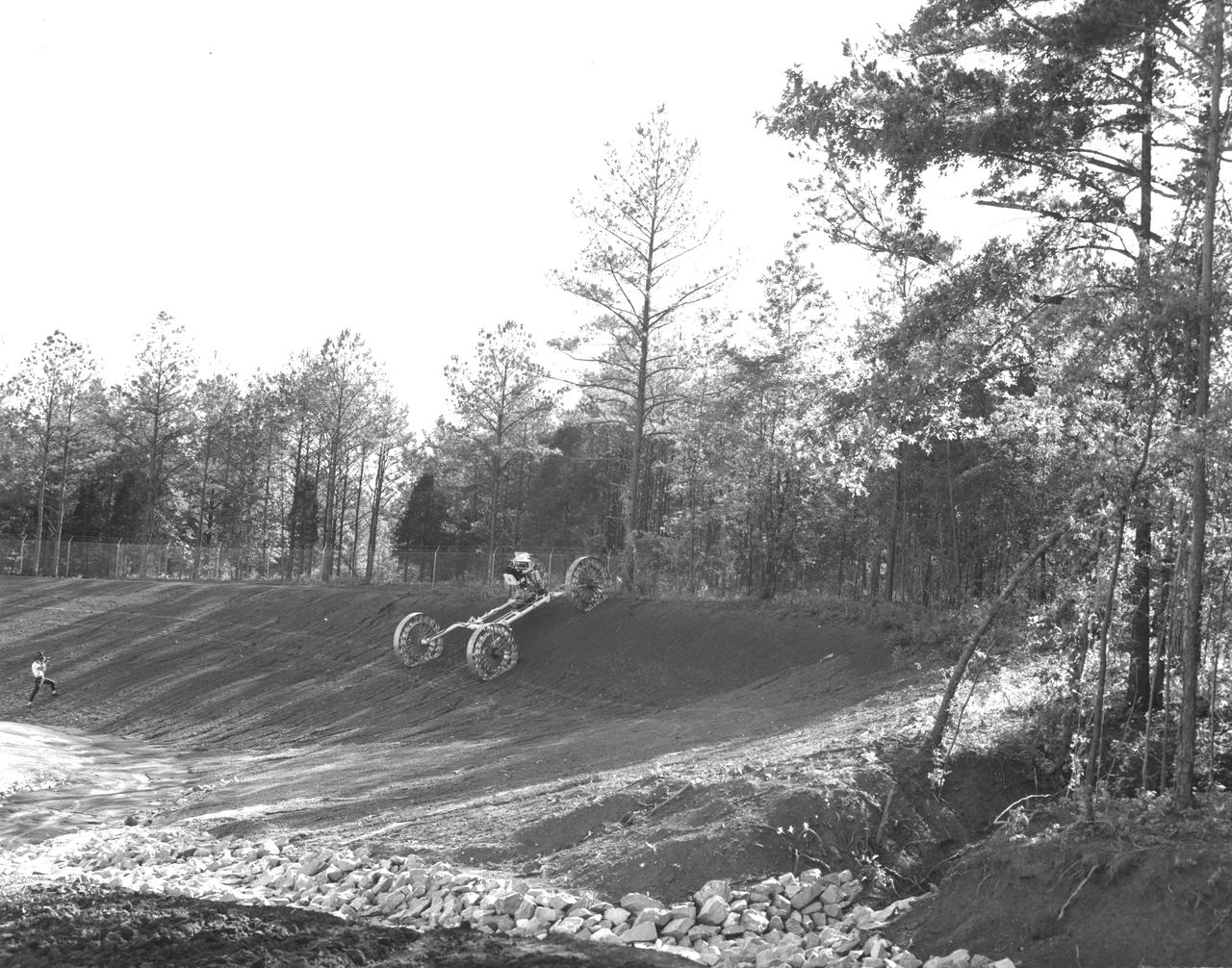
An engineer demonstrates a Mobility Test Article (MTA) at NASA’s Marshall Space Flight Center (MSFC) as he goes down a slope onto soft earth. This unit, weighing 1/6th as much as an actual vehicle, was built by the Bendix Corporation and was one of the concepts of a possible Lunar Roving Vehicle (LRV). The data provided by the MTA helped in designing the Lunar Roving Vehicle (LRV), developed under the direction of MSFC. The LRV was designed to allow Apollo astronauts a greater range of mobility during lunar exploration missions.
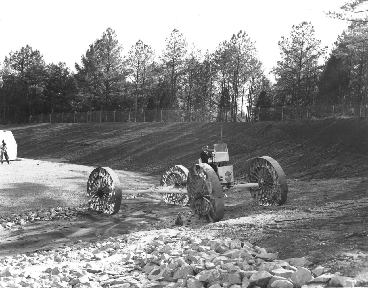
An engineer demonstrates a Mobility Test Article (MTA) at NASA’s Marshall Space Flight Center (MSFC) as he crosses a soft clay strip onto rocky ground. This unit, weighing 1/6th as much as an actual vehicle, was built by the Bendix Corporation and was one of the concepts of a possible Lunar Roving Vehicle (LRV). The data provided by the MTA helped in designing the LRV, developed under the direction of MSFC. The LRV was designed to allow Apollo astronauts a greater range of mobility during lunar exploration missions.
An engineer demonstrates a Mobility Test Article (MTA) at NASA’s Marshall Space Flight Center (MSFC). This unit, weighing 1/6th as much as an actual vehicle, was built by the Bendix Corporation and was one of the concepts of a possible Lunar Roving Vehicle (LRV). The data provided by the MTA helped in designing the LRV, developed under the direction of MSFC. The LRV was designed to allow Apollo astronauts a greater range of mobility during lunar exploration missions.
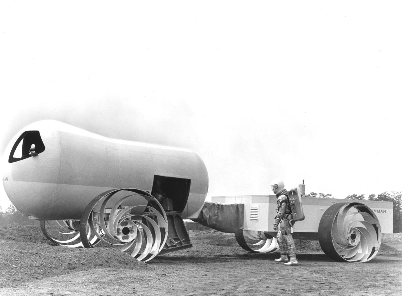
This Mobility Test Article (MTA) was a concept of a possible dual mode Lunar Roving Vehicle (LRV) built by the Grumman Industries for NASA’s Marshall Space Flight Center (MSFC). The data provided by the MTA helped in designing the Lunar Roving Vehicle (LRV), developed under the direction of MSFC. The LRV was designed to allow Apollo astronauts a greater range of mobility during lunar exploration missions.
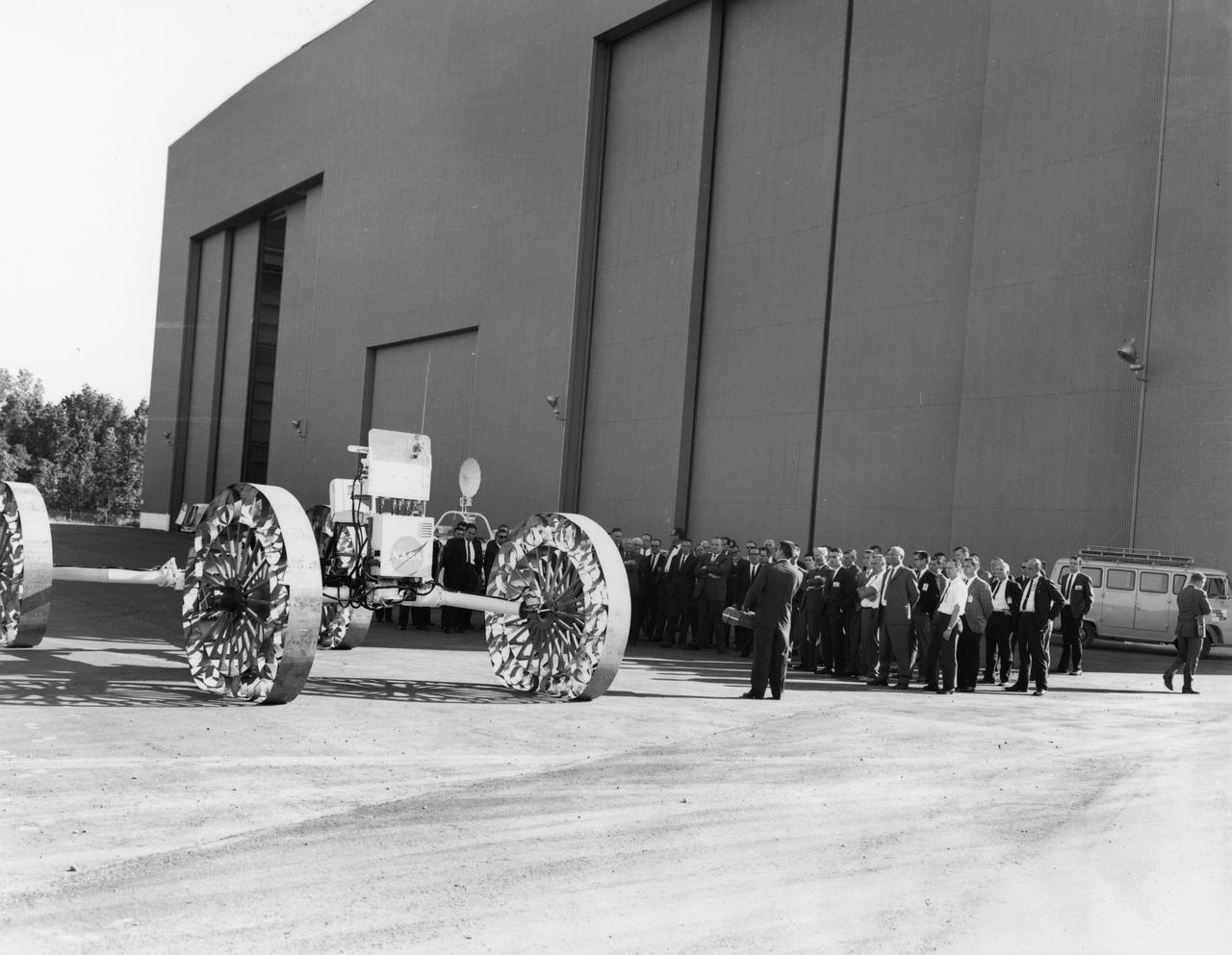
Newsmen listen as an engineer explains operations and capabilities of a Mobility Test Article (MTA) demonstrated at NASA’s Marshall Space Flight Center (MSFC). This unit, built by the Bendix Corporation, was one of the concepts of a possible Lunar Roving Vehicle (LRV). The data provided by the MTA helped in designing the LRV, developed under the direction of MSFC. The LRV was designed to allow Apollo astronauts a greater range of mobility during lunar exploration missions.
An engineer demonstrates a Mobility Test Article (MTA) at NASA’s Marshall Space Flight Center (MSFC). This unit, weighing 1/6th as much as an actual vehicle, was built by the Bendix Corporation and was one of the concepts of a possible Lunar Roving Vehicle (LRV). The data provided by the MTA helped in designing the Lunar Roving Vehicle (LRV), developed under the direction of MSFC. The LRV was designed to allow Apollo astronauts a greater range of mobility during lunar exploration missions.

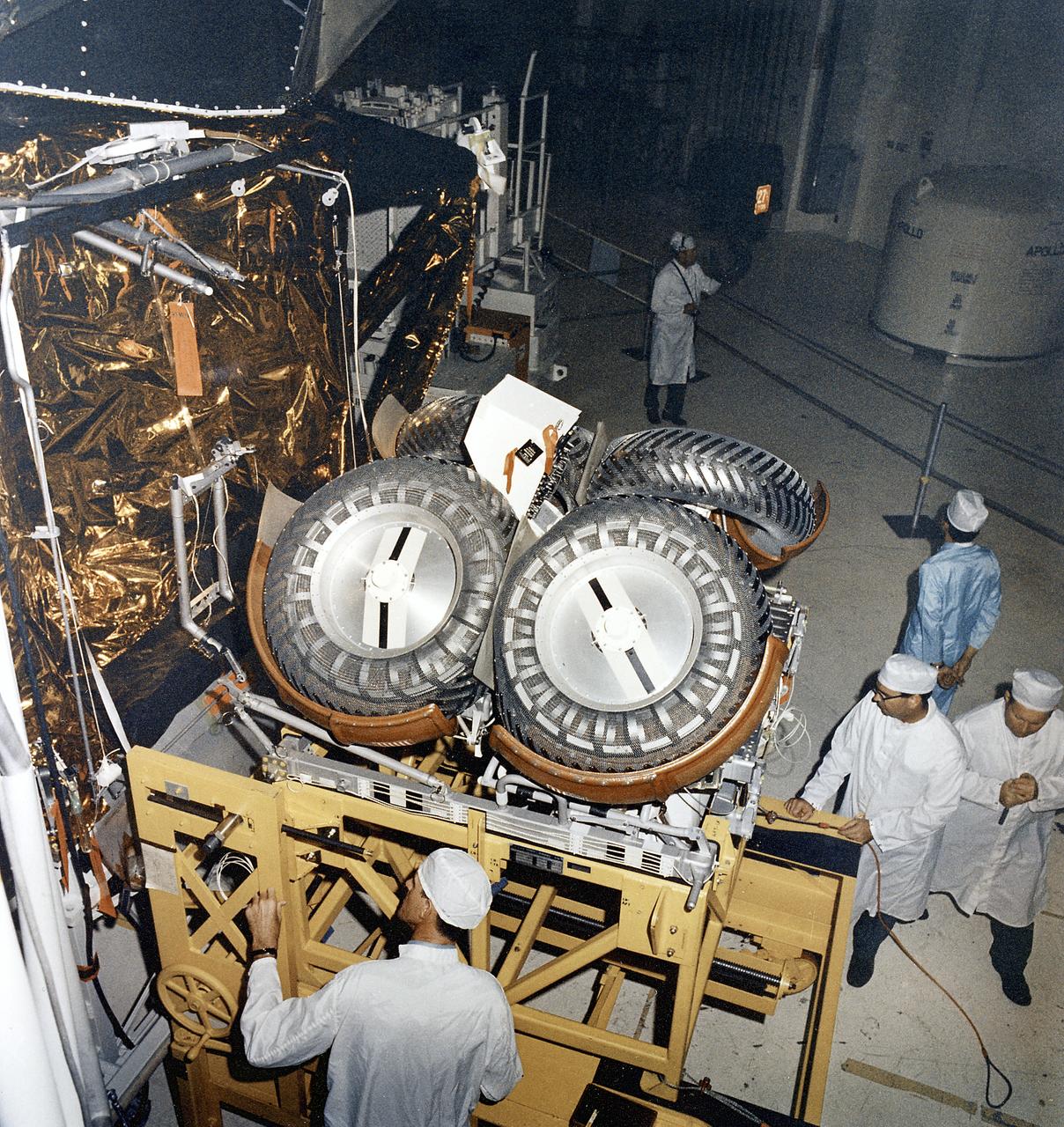
This photograph shows the Lunar Roving Vehicle (LRV) being prepared for installation in the Lunar Module at the Kennedy Space Center. The LRV was built to give Apollo astronauts a greater range of mobility during the last three lunar exploration missions; Apollo 15, Apollo 16, and Apollo 17. It was designed and developed by the Marshall Space Flight Center and built by the Boeing Company.
Built by Brown Engineering company of Huntsville, Alabama, a motorized mockup of a small Lunar Roving Vehicle (LRV) is being demonstrated at the Marshall Space Flight Center (MSFC). This particular vehicle weighed about 1200 pounds and is almost 10 feet long, 7-feet and 2-inches wide, and 7-feet and 8-inches high. The LRV was developed under the direction of MSFC to provide astronauts with greater mobility on the lunar surface.
The Lunar Roving Vehicle (LRV) was designed by Marshall Space Flight Center to transport astronauts and materials on the Moon. An LRV was used on each of the last three Apollo missions; Apollo 15, Apollo 16, and Apollo 17, in 1971 and 1972, to permit the crew to travel several miles from the lunar landing site. This photograph was taken during the Apollo 16 mission in 1972.
This photograph was taken during the installation of the Lunar Roving Vehicle (LRV) in the Lunar Module at the Kennedy Space Center. The LRV was built to give Apollo astronauts a greater range of mobility during the last three lunar exploration missions; Apollo 15, Apollo 16, and Apollo 17. It was designed and developed by the Marshall Space Flight Center and built by the Boeing Company.
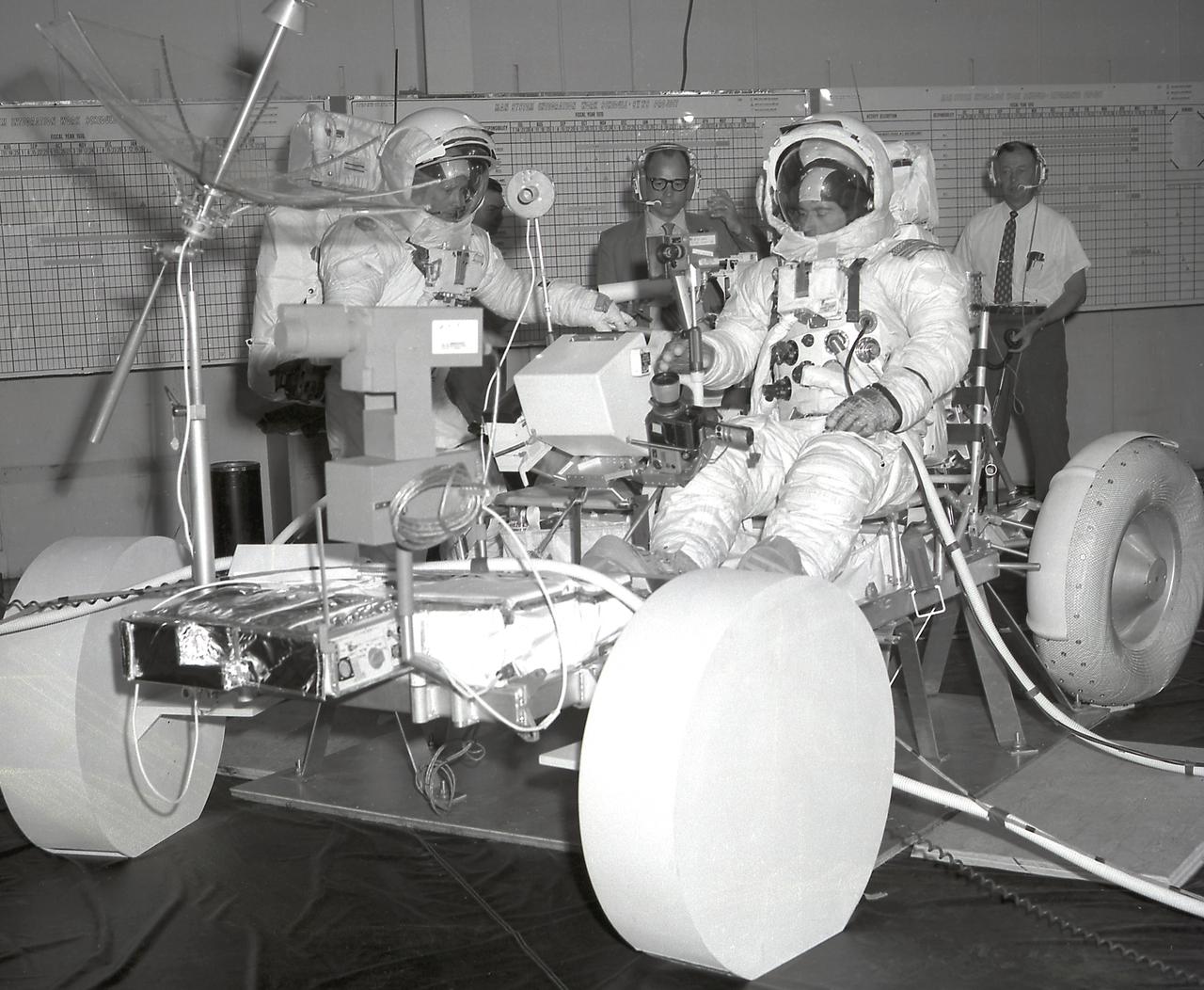
This image depicts the Apollo 16 mission astronauts John Young (right) and Charles Duke (left) in pressure suits during a final crew training on the Lunar Roving Vehicle (LRV) at the Marshall Space Flight Center (MSFC), building 4619. Developed by the MSFC, the LRV was the lightweight electric car designed to increase the range of mobility and productivity of astronauts on the lunar surface. It was used on the last three Apollo missions; Apollo 15, Apollo 16, and Apollo 17.
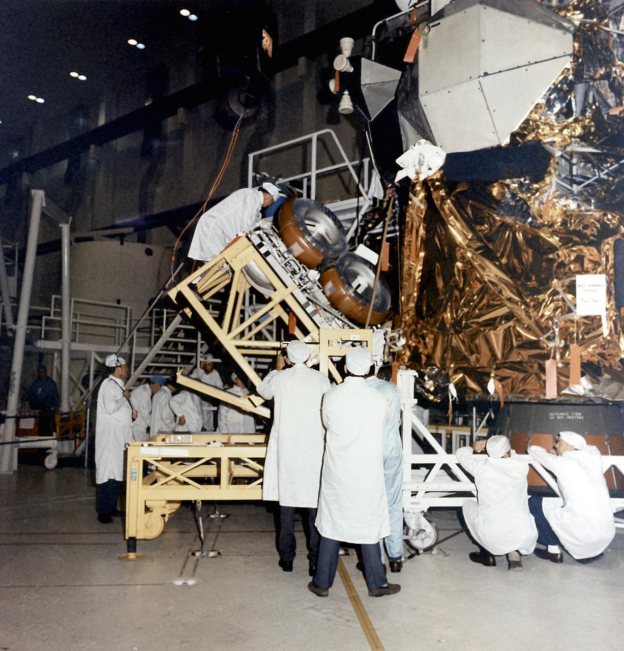
This photograph was taken during the installation of the Lunar Roving Vehicle (LRV) in the Lunar Module at the Kennedy Space Center. The LRV was built to give Apollo astronauts a greater range of mobility during the last three lunar exploration missions; Apollo 15, Apollo 16, and Apollo 17. It was designed and developed by the Marshall Space Flight Center and built by the Boeing Company.
Artist’s concept of a dual mode Lunar Roving Vehicle (LRV) on the Lunar surface. This represents the Bendix version in an unmanned configuration. The LRV was developed under the direction of MSFC to allow Apollo astronauts a greater range of mobility during lunar exploration missions.
This photograph was taken during the testing of the Lunar Roving Vehicle (LRV) at the Johnson Space Center. Developed by the MSFC, the LRV was the lightweight electric car designed to increase the range of mobility and productivity of astronauts on the lunar surface. It was used on the last three Apollo missions; Apollo 15, Apollo 16, and Apollo 17.
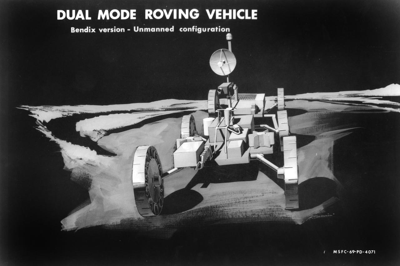
Artist’s concept of a dual mode Lunar Roving Vehicle (LRV) on the Lunar surface. This represents the Bendix version in an unmanned configuration. The LRV was developed under the direction of MSFC to allow Apollo astronauts a greater range of mobility during lunar exploration missions.
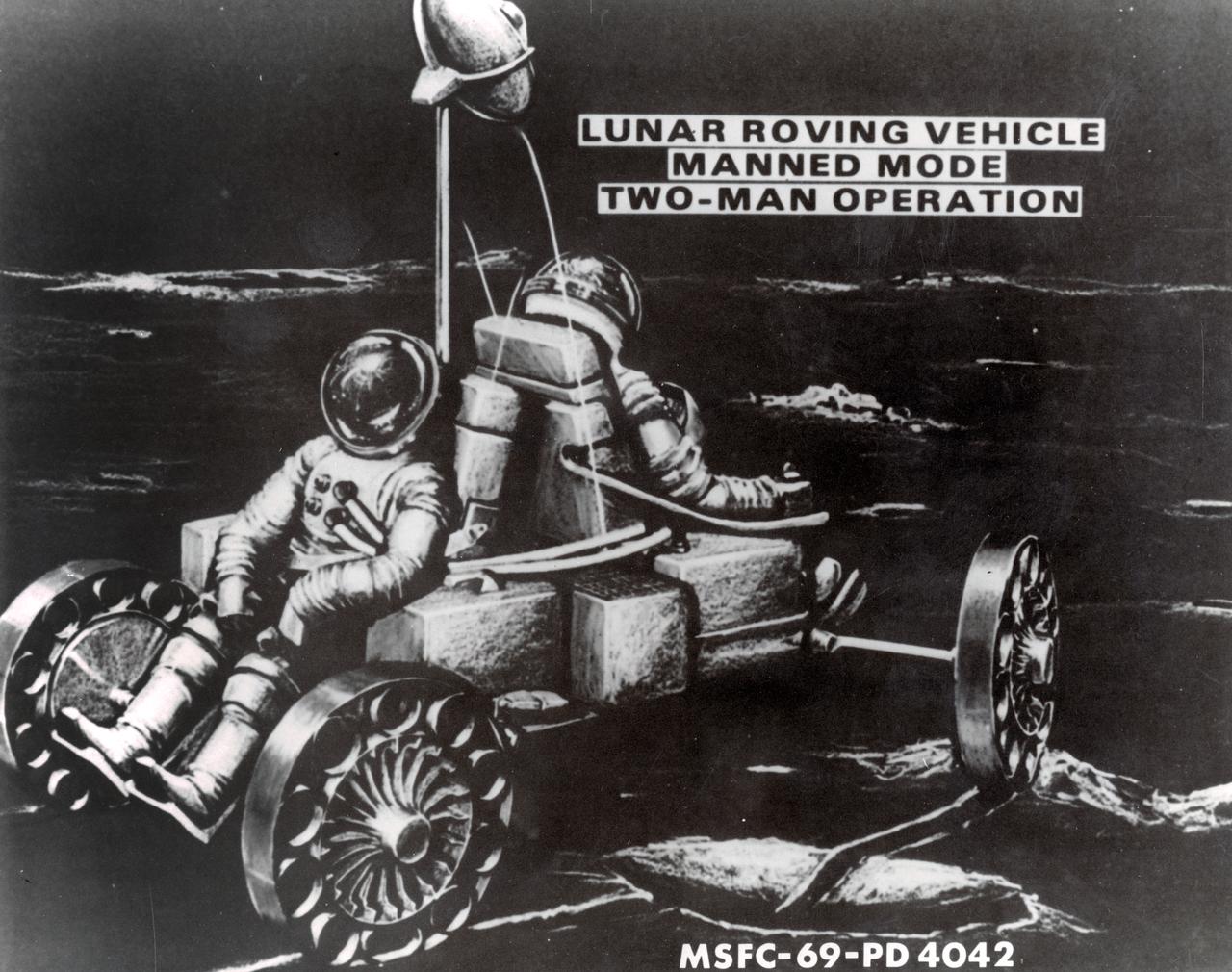
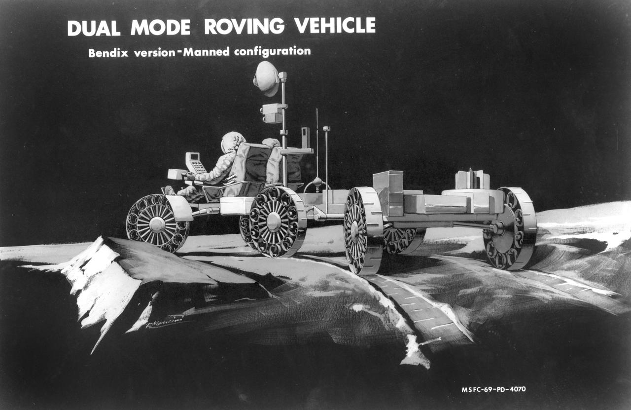
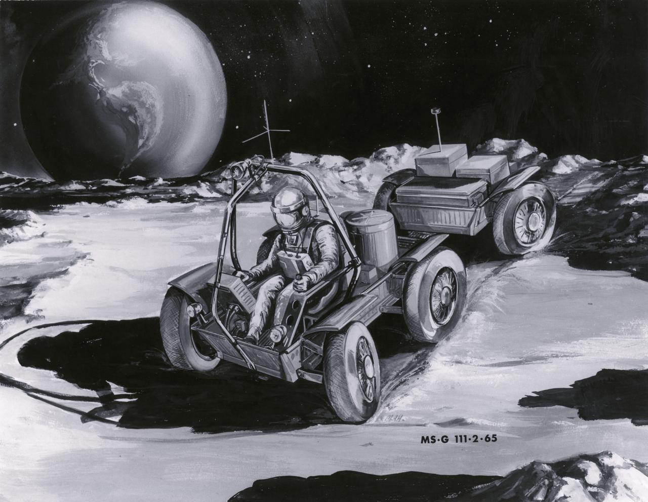
Artist’s concept of a manned Lunar Roving Vehicle (LRV) depicting two-man operation on the Lunar surface. The LRV was developed under the direction of the Marshall Space Flight Center (MSFC) to provide Apollo astronauts with a greater range of mobility on the lunar surface.

Artist’s concept of a dual mode Lunar Roving Vehicle (LRV) on the Lunar surface. This represents the Grumman version in an unmanned configuration. The LRV was developed under the direction of MSFC to allow Apollo astronauts a greater range of mobility during lunar exploration missions.
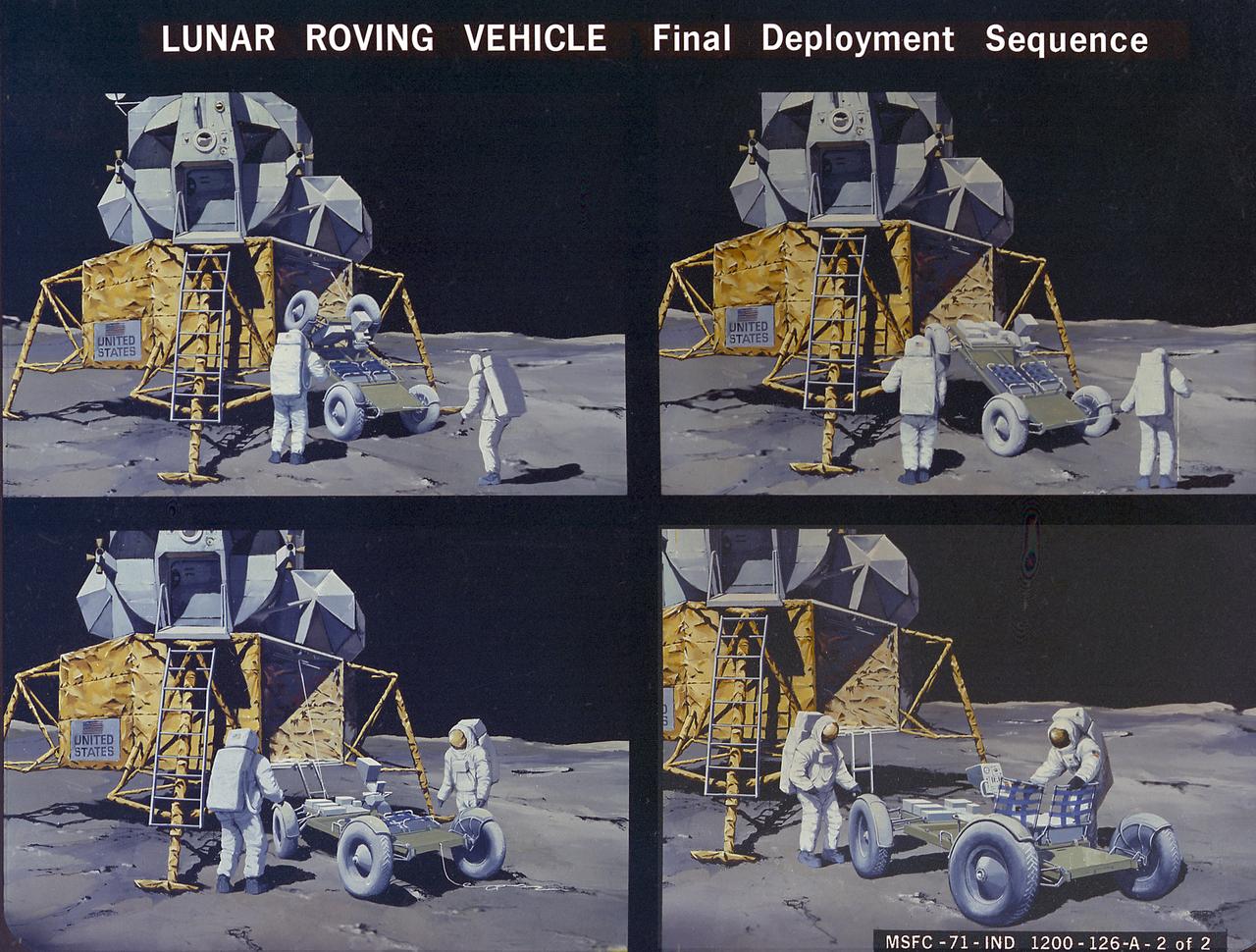
S71-38189 (26 June 1971) --- An artist's concept showing the final steps of readying the Apollo 15 Lunar Roving Vehicle (LRV) or Rover 1 for mobility on the lunar surface. Performing the last few LRV deployment tasks here are, left to right, astronauts James B. Irwin, lunar module pilot, and David R. Scott, commander. More specifically the tasks depicted here include the setting up of the seats and the total releasing of the LRV from the LM. (This is the fourth in a series of four Grumman Aerospace Corporation artist's concepts telling the lunar surface LRV deployment story for Apollo 15).
S71-38188 (26 June 1971) --- An artist's concept showing the Apollo 15 mission commander and the lunar module pilot performing deployment of the Lunar Roving Vehicle (LRV) on the lunar surface. The figure on the left represents astronaut James B. Irwin, lunar module pilot, who here is maintaining a constant pull on the deployment cable to help the LRV unfold, while astronaut David R. Scott (right), commander, pulls the tapes that lower the LRV to the surface. (This is the third in a series of Grumman Aerospace Corporation artist's concepts telling the lunar surface LRV deployment story of the Apollo 15 mission).
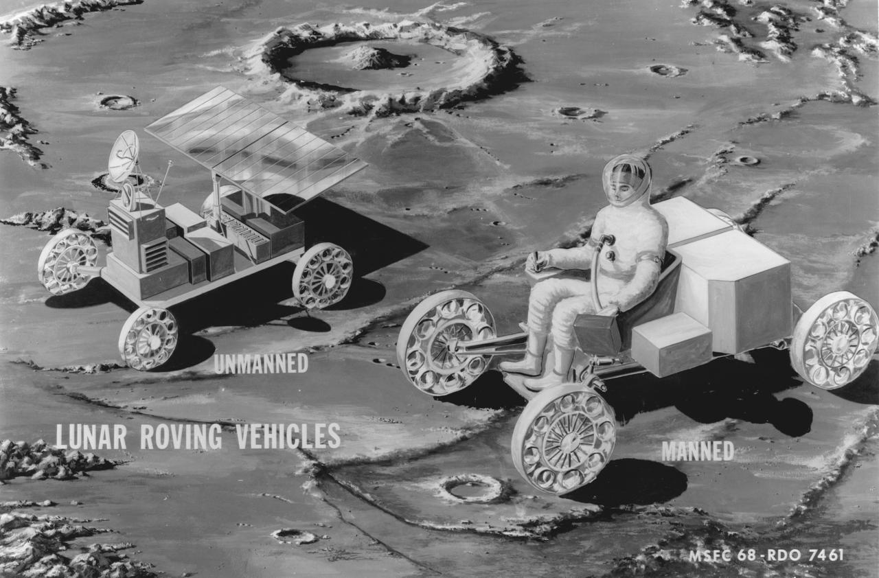
Artist’s manned and unmanned concepts of a Lunar Roving Vehicle (LRV) Mobility Test Article (MTA) on the Lunar surface. The data provided by the MTA helped in designing the LRV, developed under the direction of MSFC. The LRV was designed to allow Apollo astronauts a greater range of mobility during lunar exploration missions.
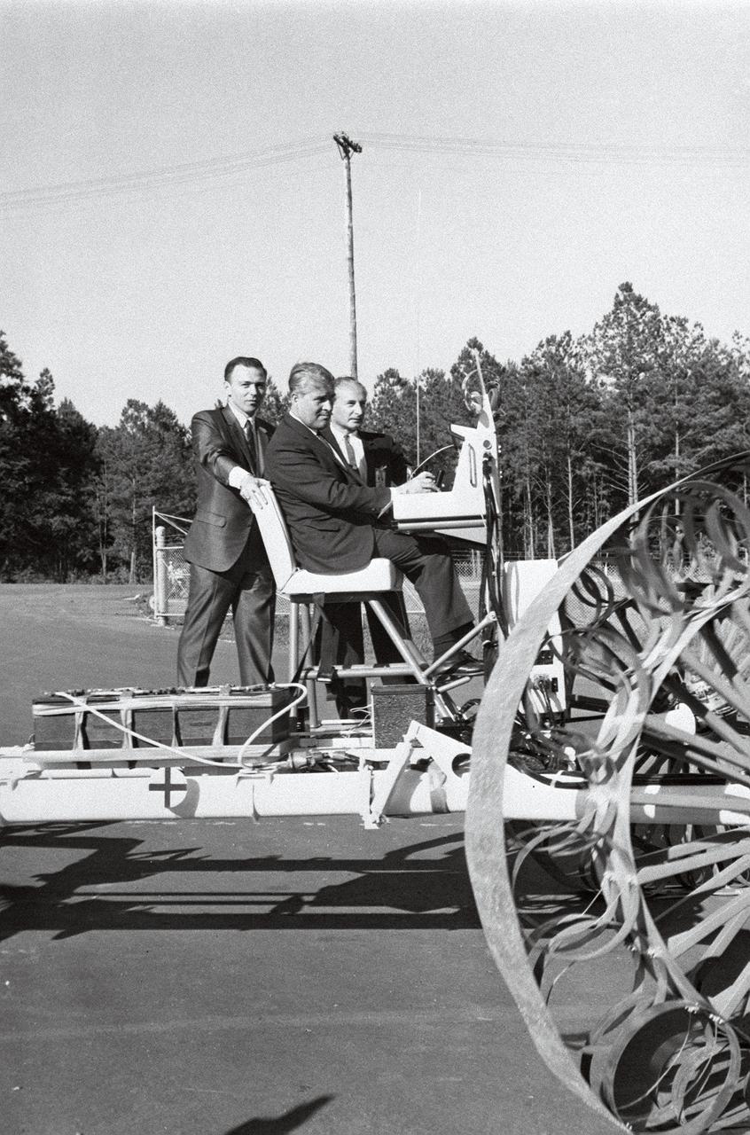
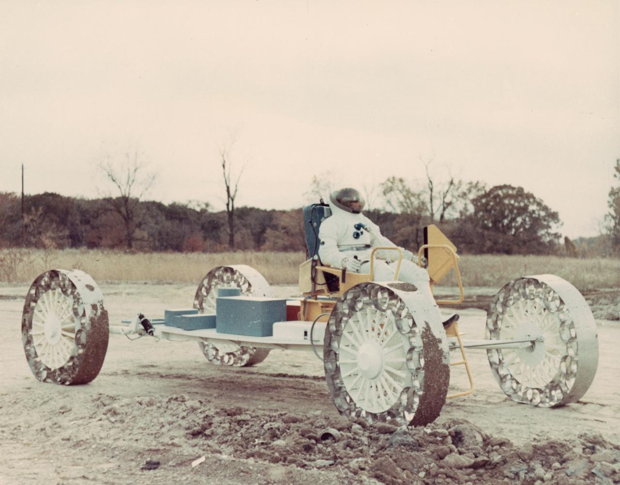
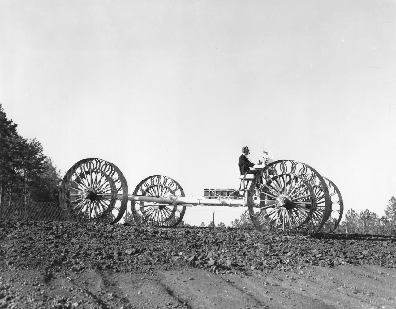
In this June 1966 photograph, Marshall Space Flight Center Director Dr. Wernher von Braun test-drives the Mobility Test Article (MTA), a developmental vehicle built by the Bendix Corporation to test lunar mobility vehicle concepts. The data provided by the MTA helped in designing the Lunar Roving Vehicle (LRV), developed under the direction of the MSFC. The LRV was designed to allow Apollo astronauts a greater range of mobility during lunar exploration missions. The LRVs were deployed during the last three Apollo missions; Apollo 15, Apollo 16, and Apollo 17.
S71-00166 (June 1971) --- A close-up view of the Lunar Roving Vehicle (LRV). Apollo 15 will be the first mission to employ the services of the LRV. Astronauts David R. Scott, commander; and James B. Irwin, lunar module pilot, will move about the lunar surface in the Hadley-Apennine region in their four-wheeled vehicle while astronaut Alfred M. Worden, command module pilot, remains with the Command and Service Modules (CSM) in lunar orbit. A television camera, which can be controlled remotely from the ground (front), and a motion picture camera (rear) are among the gear on the LRV.
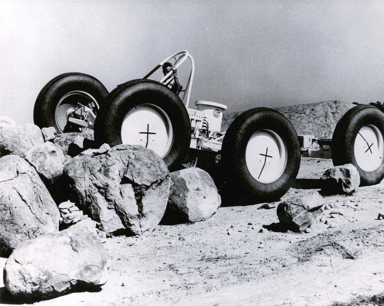
A test engineer drove a Mobility Test Article (MTA) of a possible future Lunar Roving Vehicle (LRV) over rocks during tests in Arizona. The machine was built by General Motors for NASA’s Marshall Space Flight Center (MSFC). Under the direction of MSFC, the LRV was designed to allow Apollo astronauts a greater range of mobility during lunar exploration missions.
This Mobility Test Article (MTA), built by the Bendix Corporation for NASA’s Marshall Space Flight Center (MSFC), was driven over rocks in Arizona. The data provided by the MTA helped in designing the Lunar Roving Vehicle (LRV), developed under the direction of the MSFC. The LRV was designed to allow Apollo astronauts a greater range of mobility during lunar exploration missions.
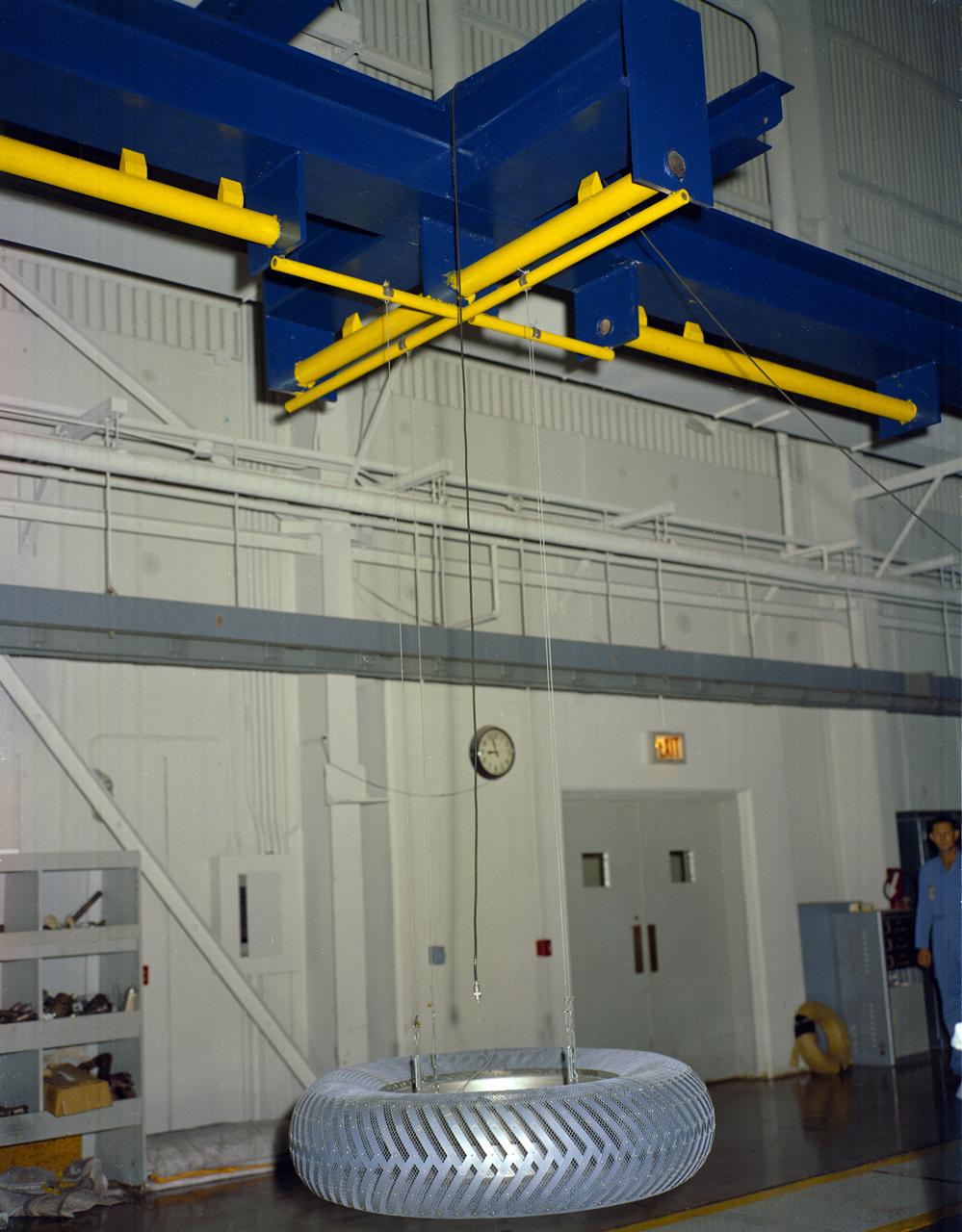
Under the direction of Marshall Space Flight Center (MSFC), the Lunar Roving Vehicle (LRV) was designed to allow Apollo astronauts a greater range of mobility during lunar exploration missions. During the development process, LRV prototype wheels underwent soil tests in building 4481 at Marshall Space Flight Center (MSFC). Pictured is the GM wheel design.
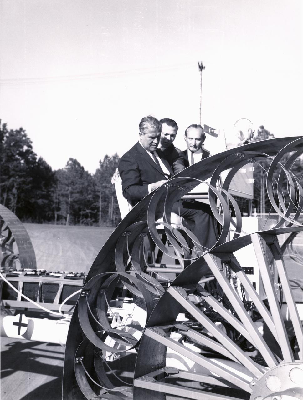
Marshall Space Flight Center (MSFC) director, Wernher von Braun, and others examine one concept of a possible Lunar Roving Vehicle (LRV) built by the Bendix Corporation. The data provided by the MTA helped in designing the LRV, developed under the direction of MSFC. The LRV was designed to allow Apollo astronauts a greater range of mobility during lunar exploration missions.
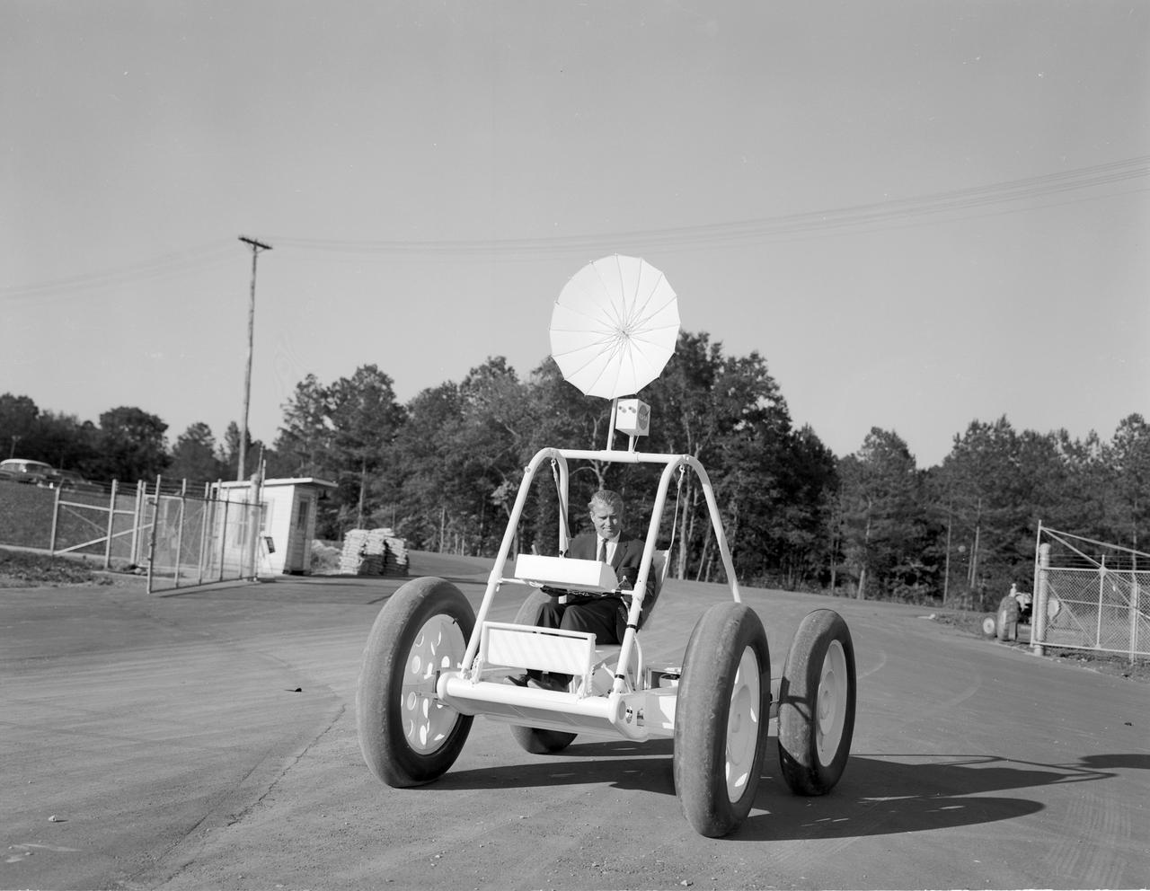
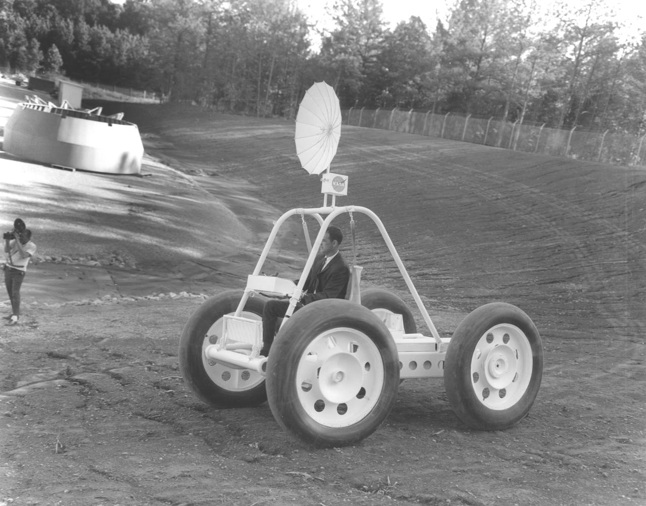
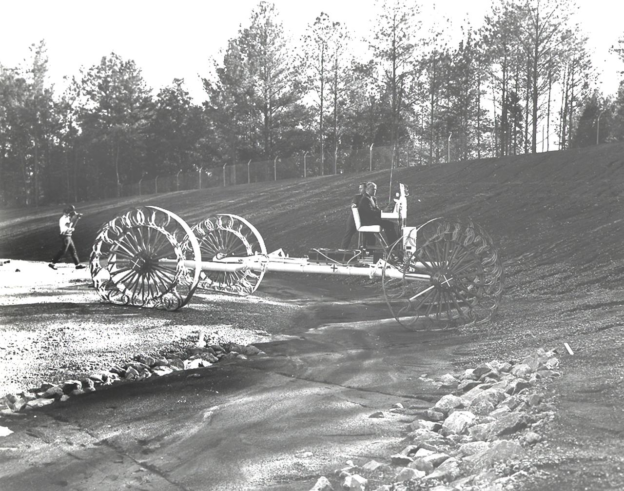
Dr. von Braun, director of NASA’s Marshall Space Flight Center (MSFC), is driving a small vehicle used in the studies of modes for transportation on the moon’s surface. From those studies evolved the Lunar Roving Vehicle (LRV).

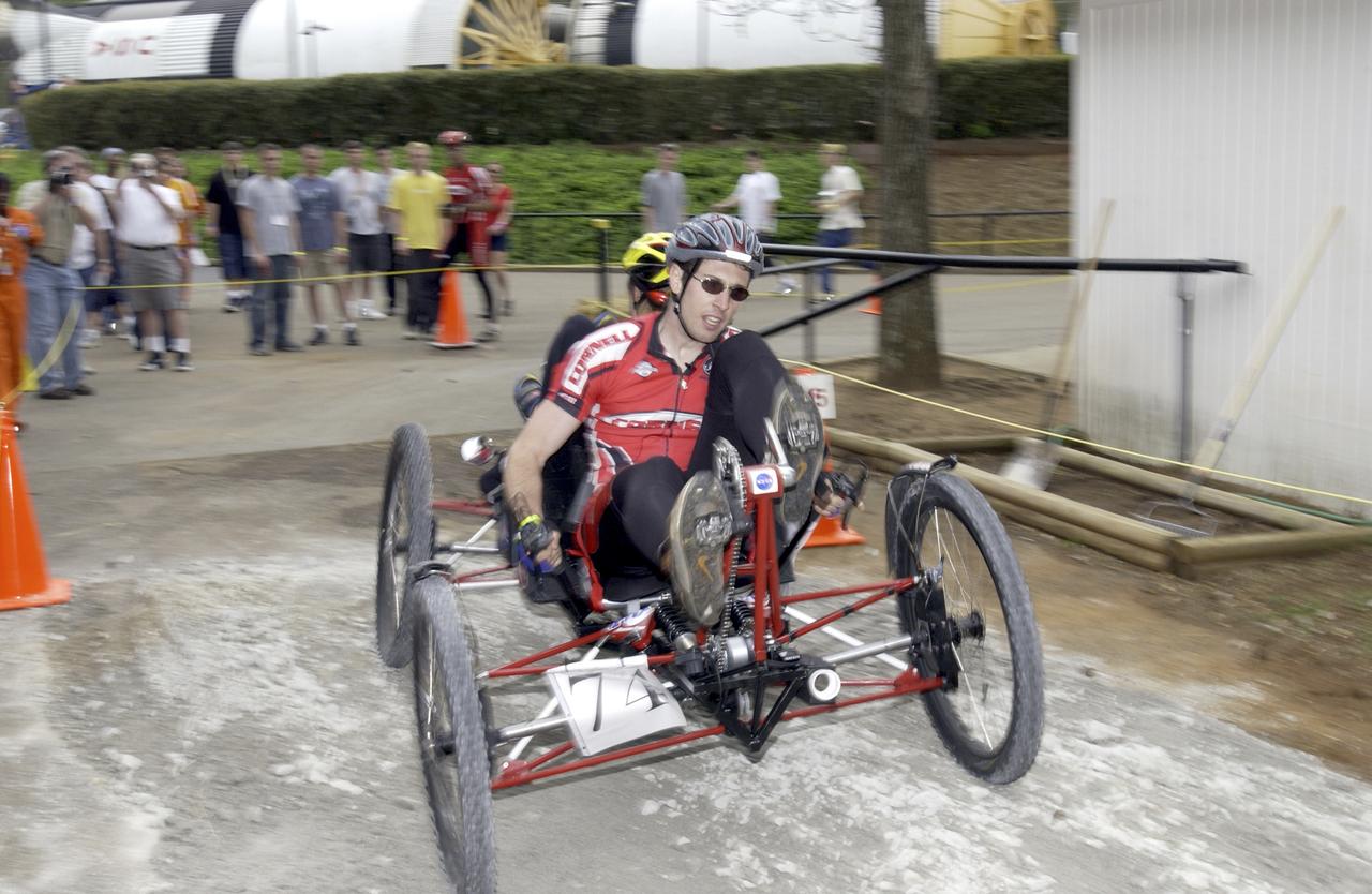
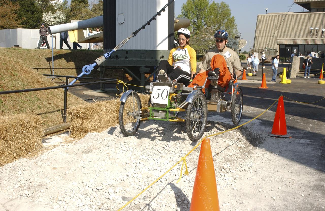
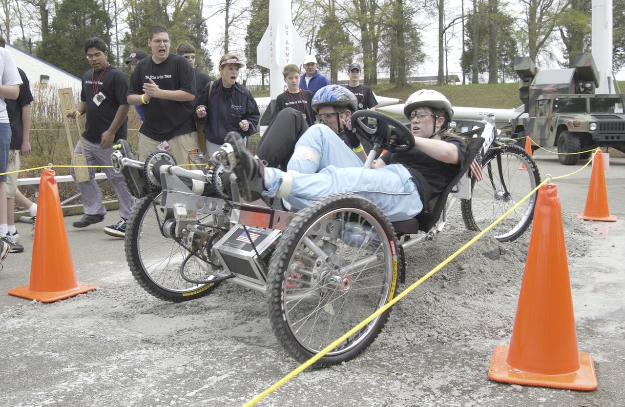
Students from across the United States and as far away as Puerto Rico and South America came to Huntsville, Alabama for the 9th annual Great Moonbuggy Race at the U.S. Space Rocket Center. Seventy-seven teams, representing high schools and colleges from 21 states, Puerto Rico, and Columbia, raced human powered vehicles over a lunar-like terrain. A team from Cornell University in Ithaca, New York, took the first place honor in the college division. This photograph shows the Cornell #2 team driving their vehicle through the course. The team finished the race in second place in the college division. Vehicles powered by two team members, one male and one female, raced one at a time over a half-mile obstacle course of simulated moonscape terrain. The competition is inspired by development, some 30 years ago, of the Lunar Roving Vehicle (LRV), a program managed by the Marshall Space Flight Center. The LRV team had to design a compact, lightweight, all-terrain vehicle, that could be transported to the Moon in the small Apollo spacecraft. The Great Moonbuggy Race challenges students to design and build a human powered vehicle so they will learn how to deal with real-world engineering problems, similar to those faced by the actual NASA LRV team.
Students from across the United States and as far away as Puerto Rico and South America came to Huntsville, Alabama for the 9th annual Great Moonbuggy Race at the U.S. Space Rocket Center. Seventy-seven teams, representing high schools and colleges from 21 states, Puerto Rico, and Columbia, raced human powered vehicles over a lunar-like terrain. A team from Cornell University in Ithaca, New York, took the first place honor in the college division. In this photograph, the Cornell #1 team, the collegiate first place winner, maneuvers their vehicle through the course. Vehicles powered by two team members, one male and one female, raced one at a time over a half-mile obstacle course of simulated moonscape terrain. The competition is inspired by development, some 30 years ago, of the Lunar Roving Vehicle (LRV), a program managed by the Marshall Space Flight Center. The LRV team had to design a compact, lightweight, all-terrain vehicle that could be transported to the Moon in the small Apollo spacecraft. The Great Moonbuggy Race challenges students to design and build a humanpowered vehicle so they will learn how to deal with real-world engineering problems similar to those faced by the actual NASA LRV team.

This in an aerial view (looking east) of a Lunar Roving Vehicle (LRV), often referred to as “Moonbuggy”, simulator area built at the Marshall Space Flight Center (MSFC) where testing was performed. The LRV was developed under the direction of MSFC to provide astronauts with greater mobility on the lunar surface. Visible in the background is the 18-acre facility known as the Random Motion/ Lift-Off Simulator or ‘Arm Farm’ which was developed to test the Saturn swingarm mechanisms that were used to hold the rocket in position until lift-off.
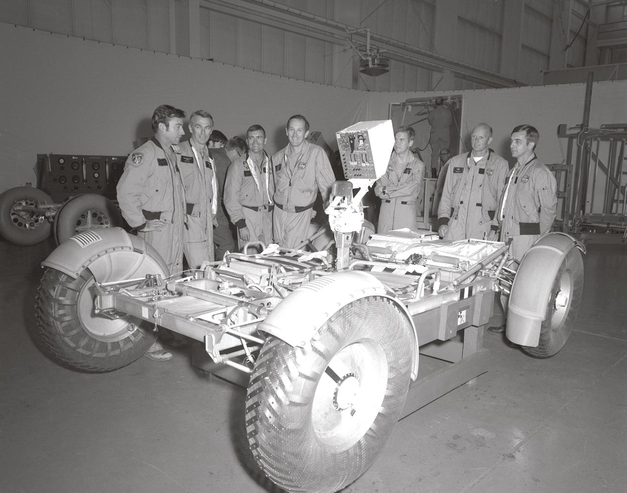
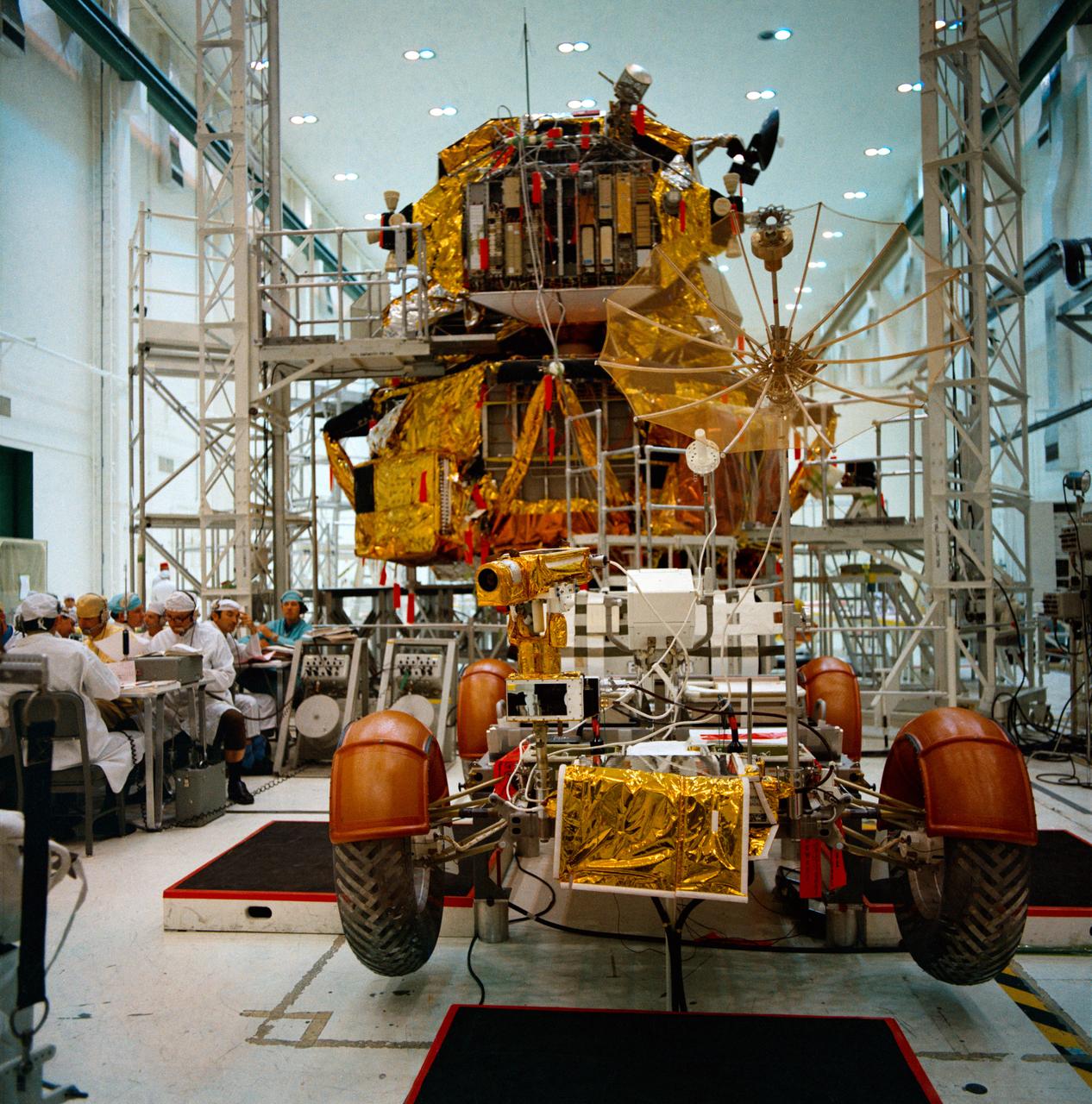
In this November 1971 photograph, (from left to right) Astronauts John Young, Eugene Cernan, Charles Duke, Fred Haise, Anthony England, Charles Fullerton, and Donald Peterson await deployment tests of the Lunar Roving Vehicle (LRV) qualification test unit in building 4649 at the Marshall Space Flight Center (MSFC). The LRV, developed under the direction of the MSFC, was designed to allow Apollo astronauts a greater range of mobility on the lunar surface during the last three lunar exploration missions; Apollo 15, Apollo 16, and Apollo 17.
Artist’s concept of the Local Scientific Survey Module (LSSM), one of two designs for a Lunar Roving Vehicle (LRV), depicted on the lunar surface A Bendix Corporation concept, this configuration weighs more than 8,000 pounds, is 21-feet long, 15-feet wide and has 6 wheels with 5-foot diameters. The LRV was developed under the direction of the Marshall Space Flight Center (MSFC) to give Apollo astronauts a wider range of mobility on the lunar surface.
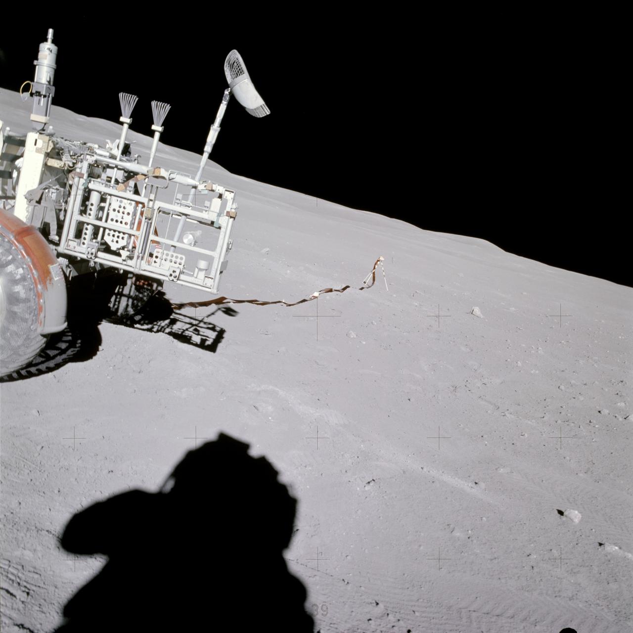
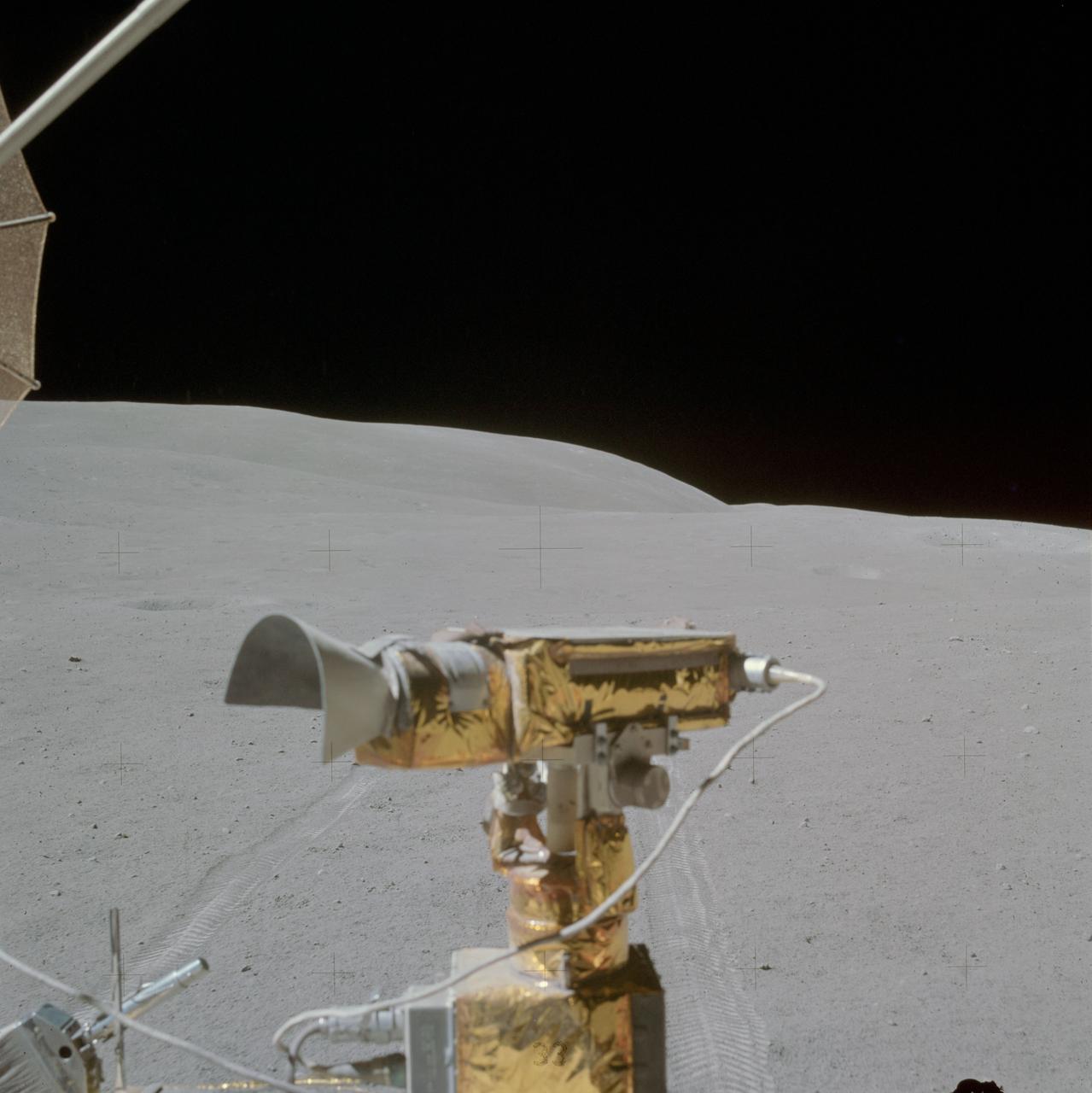
AS16-114-18433 (22 April 1972) --- View of the Lunar Portable Magnetometer mounted on the Lunar Roving Vehicle (LRV) which was parked at Station No. 2 on the Descartes lunar landing site. The Apollo 16 crew photographed it during their second extravehicular activity (EVA). Note the shadow of the astronaut taking the photograph in the left foreground.
In this June, 1966 photograph, Marshall Space Flight Center Director, Dr. Wernher von Braun test drives the Mobility Test Article (MTA), a developmental vehicle built by the Bendix Corporation to test lunar mobility concepts. The data provided by the MTA helped in designing the Lunar Roving Vehicle (LRV), developed under the direction of the Marshall Space Flight Center. The LRV was designed to allow Apollo astronauts a greater range during lunar exploration missions and served its purpose during the last three Apollo lunar missions in 1971 and 1972.
Students from across the United States and as far away as Puerto Rico came to Huntsville, Alabama for the 10th annual Great Moonbuggy Race at the U.S. Space Rocket Center. Sixty-eight teams, representing high schools and colleges from all over the United States, and Puerto Rico, raced human powered vehicles over a lunar-like terrain. Vehicles powered by two team members, one male and one female, raced one at a time over a half-mile obstacle course of simulated moonscape terrain. The competition is inspired by development, some 30 years ago, of the Lunar Roving Vehicle (LRV), a program managed by the Marshall Space Flight Center. The LRV team had to design a compact, lightweight, all-terrain vehicle that could be transported to the Moon in the small Apollo spacecraft. The Great Moonbuggy Race challenges students to design and build a human powered vehicle so they will learn how to deal with real-world engineering problems similar to those faced by the actual NASA LRV team. In this photograph, Team No. 1 from North Dakota State University in Fargo conquers one of several obstacles on their way to victory. The team captured first place honors in the college level competition.
Students from across the United States and as far away as Puerto Rico and South America came to Huntsville, Alabama for the 9th annual Great Moonbuggy Race at the U.S. Space Rocket Center. Seventy-seven teams, representing high schools and colleges from 21 states, Puerto Rico, and Columbia, raced human powered vehicles over a lunar-like terrain. In this photograph, the New Orleans area schools team #2 from New Orleans, Louisiana maneuvers through an obstacle course. The team captured second place in the high school division competition. Vehicles powered by two team members, one male and one female, raced one at a time over a half-mile obstacle course of simulated moonscape terrain. The competition is inspired by the development, some 30 years ago, of the Lunar Roving Vehicle (LRV), a program managed by the Marshall Space Flight Center. The LRV team had to design a compact, lightweight, all-terrain vehicle that could be transported to the Moon in the small Apollo spacecraft. The Great Moonbuggy Race challenges students to design and build a human powered vehicle so they will learn how to deal with real-world engineering problems, similar to those faced by the actual NASA LRV team.
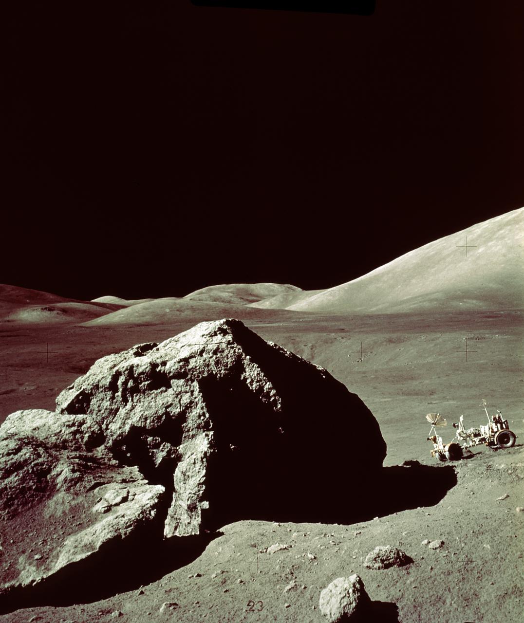
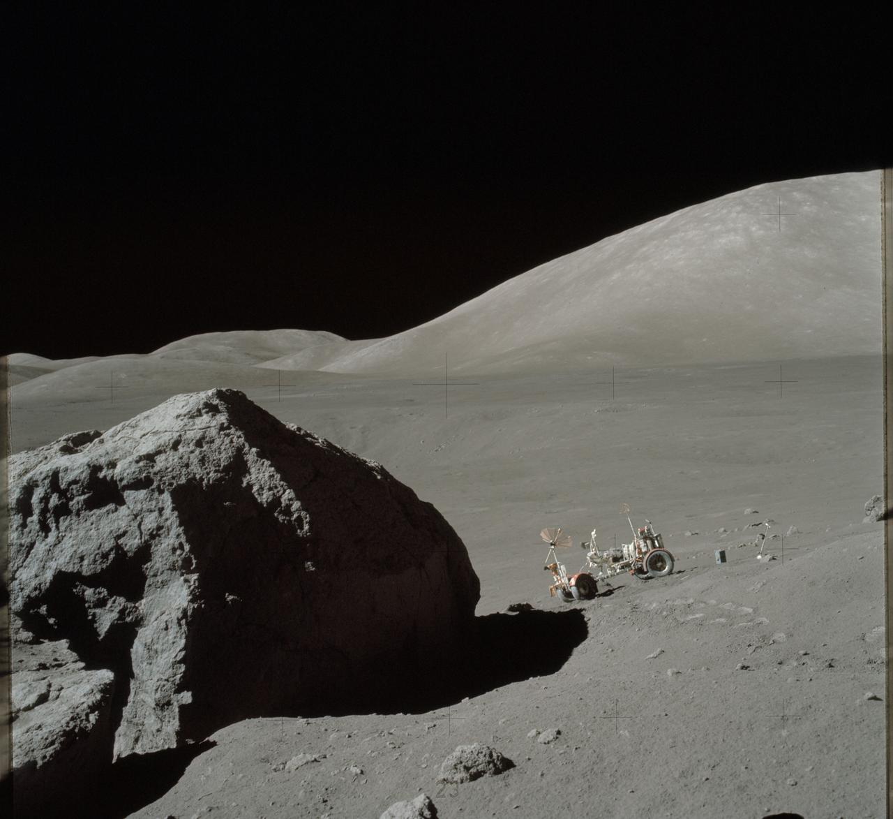
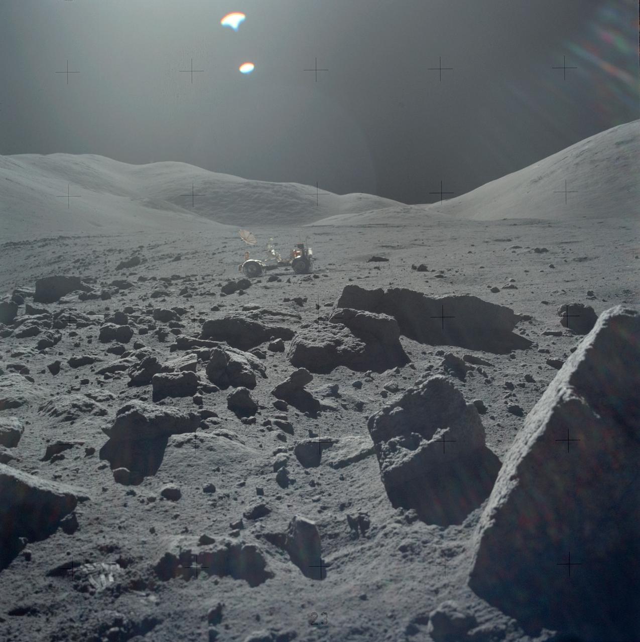
In this Apollo 17 onboard photo, a Lunar Roving Vehicle (LRV) is parked beside a huge boulder near the Valley of Tourus-Litttrow on the lunar surface. The seventh and last manned lunar landing and return to Earth mission, the Apollo 17, carrying a crew of three astronauts: Mission Commander Eugene A. Cernan; Lunar Module pilot Harrison H. Schmitt; and Command Module pilot Ronald E. Evans, lifted off on December 7, 1972 from the Kennedy Space Flight Center (KSC). Scientific objectives of the Apollo 17 mission included geological surveying and sampling of materials and surface features in a preselected area of the Taurus-Littrow region, deploying and activating surface experiments, and conducting in-flight experiments and photographic tasks during lunar orbit and transearth coast (TEC). These objectives included: Deployed experiments such as the Apollo lunar surface experiment package (ALSEP) with a Heat Flow experiment, Lunar seismic profiling (LSP), Lunar surface gravimeter (LSG), Lunar atmospheric composition experiment (LACE) and Lunar ejecta and meteorites (LEAM). The mission also included Lunar Sampling and Lunar orbital experiments. Biomedical experiments included the Biostack II Experiment and the BIOCORE experiment. The mission marked the longest Apollo mission, 504 hours, and the longest lunar surface stay time, 75 hours, which allowed the astronauts to conduct an extensive geological investigation. They collected 257 pounds (117 kilograms) of lunar samples with the use of the Marshall Space Flight Center developed LRV. The mission ended on December 19, 1972
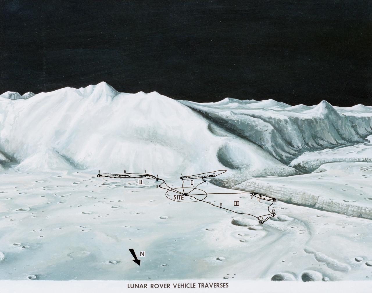
S71-33433 (1 July 1971) --- An artist's concept of the Hadley-Apennine landing site, depicting the traverses planned on the Apollo 15 lunar landing mission using the Lunar Roving Vehicle (LRV). The Roman numerals indicate the three periods of extravehicular activity (EVA). The Arabic numbers represent the station stops. This artist's concept was excerpted from "On the Moon with Apollo 15: A Guidebook to Hadley Rille and the Apennine Mountains," by Gene Simmons. The station stops indicated here are keyed to information given in the publication. Artwork by Jerry Elmore.
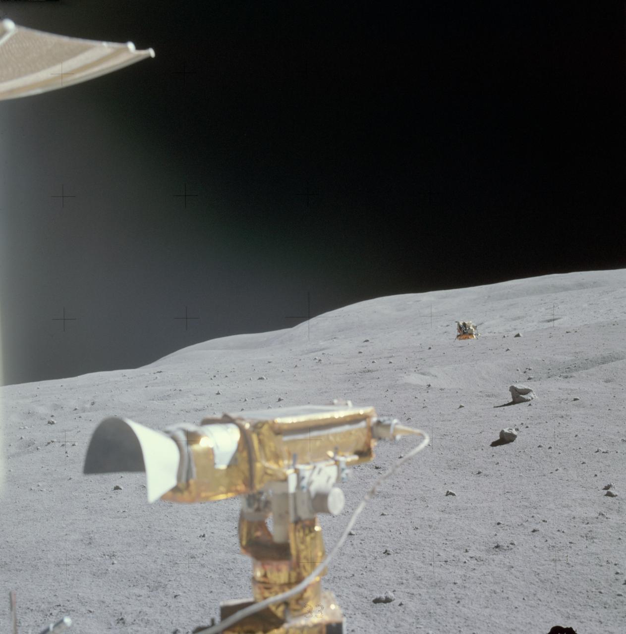
AS16-117-18754 (23 April 1972) --- A view of the smooth terrain in the general area of the North Ray Crater geological site, photographed by the Apollo 16 crew from the Lunar Roving Vehicle (LRV) shortly after leaving the immediate area of the geology site. The RCA color television camera is mounted on the front of the LRV and can be seen in the foreground, along with a small part of the high gain antenna, upper left. The tracks were made on the earlier trip to the North Ray Crater site. Astronaut Charles M. Duke Jr., lunar module pilot, exposed this view with his 70mm Hasselblad camera. Astronaut John W. Young, commander, said that this area was much smoother than the region around South Ray Crater. While astronauts Young and Duke descended in the Apollo 16 Lunar Module (LM) "Orion" to explore the Descartes highlands landing site on the moon, astronaut Thomas K. Mattingly II, command module pilot, remained with the Command and Service Modules (CSM) "Casper" in lunar orbit.
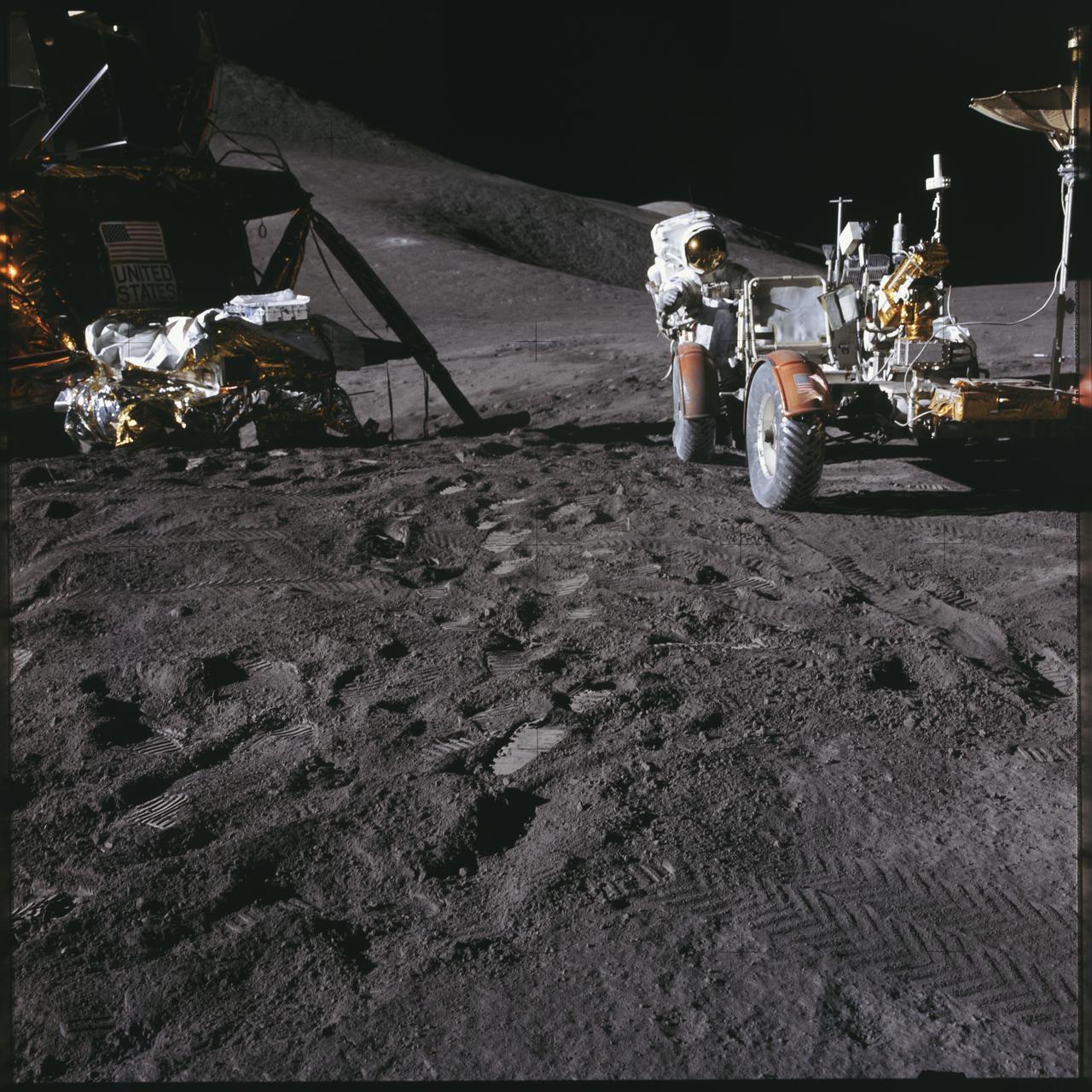
AS17-140-21388 (7-19 Dec. 1972) --- Astronaut Eugene A. Cernan, mission commander, walks toward the Lunar Roving Vehicle (LRV) during extravehicular activity (EVA) at the Taurus-Littrow landing site of NASA's sixth and final Apollo lunar landing mission. The photograph was taken by astronaut Harrison H. Schmitt, lunar module pilot. While astronauts Cernan and Schmitt descended in the Lunar Module (LM) "Challenger" to explore the Taurus-Littrow region of the moon, astronaut Ronald E. Evans, command module pilot, remained with the Command and Service Modules (CSM) "America" in lunar orbit.
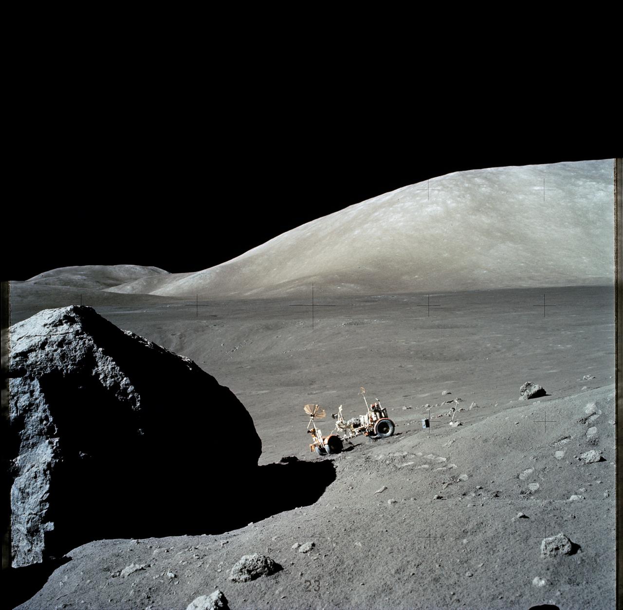
AS17-140-21493 (13 Dec. 1972) --- The Apollo 17 Lunar Roving Vehicle (LRV) is photographed near a large lunar boulder during the third Apollo 17 extravehicular activity (EVA) at the Taurus-Littrow landing site. About half of the boulder is captured in this scene, photographed by astronaut Eugene A. Cernan, mission commander. While astronauts Cernan and Harrison H. Schmitt descended in the Lunar Module (LM) "Challenger" to explore the lunar surface, astronaut Ronald E. Evans, command module pilot, remained with the Command and Service Modules (CSM) in lunar orbit.
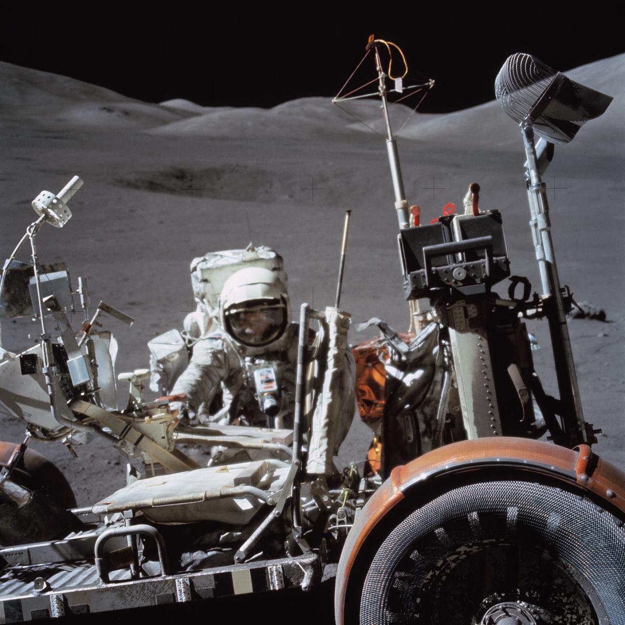
AS16-116-18578 (21 April 1972) --- Astronaut John W. Young, commander of the Apollo 16 lunar landing mission, works at the Lunar Roving Vehicle (LRV) just prior to deployment of the Apollo Lunar Surface Experiments Package (ALSEP) during the first extravehicular activity (EVA) on April 21, 1972. Note the Ultraviolet (UV) Camera/Spectrometer to the right of the Lunar Module (LM) ladder. Also, note the pile of protective/thermal foil under the U.S. flag on the LM which the astronauts pulled away to get to the Modular Equipment Storage Assembly (MESA) bay. While astronauts Young and Charles M. Duke Jr., lunar module pilot; descended in the Apollo 16 LM "Orion" to explore the Descartes highlands landing site on the moon, astronaut Thomas K. Mattingly II, command module pilot, remained with the Command and Service Modules (CSM) "Casper" in lunar orbit.
AS17-147-22523 (11 Dec. 1972) --- Astronaut Eugene A. Cernan is seen test driving the "stripped down" Lunar Rover Vehicle (LRV) prior to loading the LRV up. Equipment later loaded onto the LRV included the ground controlled television assembly, the lunar communications relay unit, the hi-gain antenna, the low-gain antenna, aft tool pallet, and lunar tools and scientific gear.
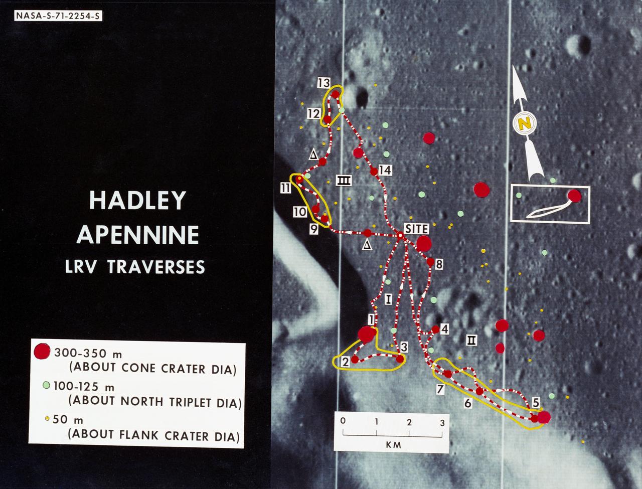
S71-02254 (June 1971) --- An enlarged Lunar Orbiter photograph showing the Lunar Roving Vehicle (LRV) traverse routes overlaid on the Hadley-Apennine landing site. Apollo 15 is to land at the point labeled "site," and a comparison of Apollo 14 crater sizes with those of Apollo 15 is included, also. While astronauts David R. Scott, commander, and James B. Irwin, lunar module pilot, descend in the Lunar Module (LM) "Falcon" to explore the moon, astronaut Alfred M. Worden, command module pilot, will remain with the Command and Service Modules (CSM) in lunar orbit.
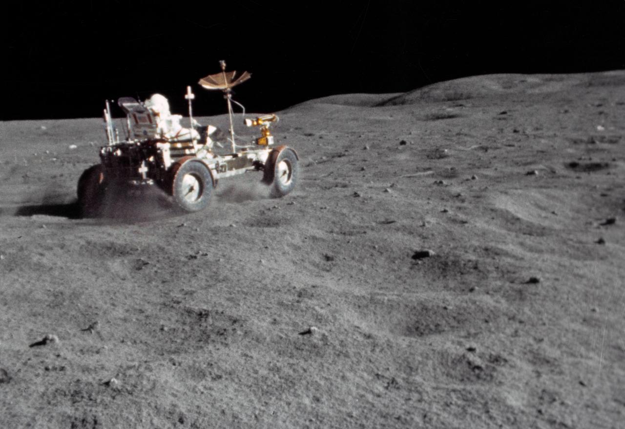
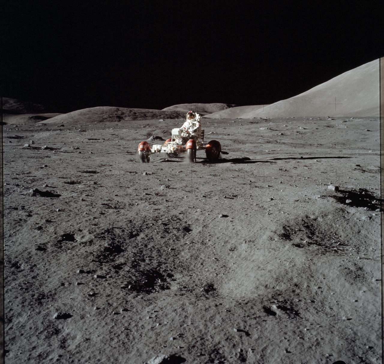
S72-37002 (21 April 1972) --- The Lunar Roving Vehicle (LRV) gets a speed workout by astronaut John W. Young in the "Grand Prix" run during the first Apollo 16 extravehicular activity (EVA) at the Descartes landing site. This view is a frame from motion picture film exposed by a 16mm Maurer camera held by astronaut Charles M. Duke Jr. While astronauts Young, commander, and Duke, lunar module pilot, descended in the Lunar Module (LM) "Orion" to explore the Descartes highlands region of the moon, astronaut Thomas K. Mattingly II, command module pilot, remained with the Command and Service Modules (CSM) "Casper" in lunar orbit.
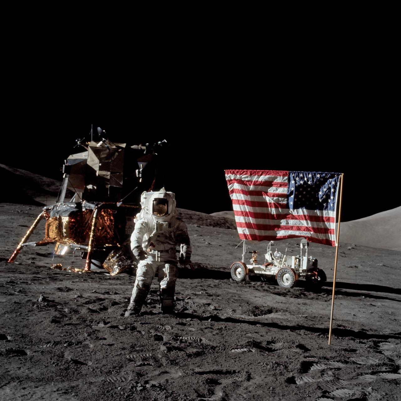
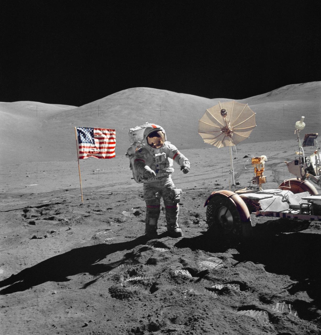
AS17-134-20382 (13 Dec. 1972) --- Astronaut Harrison H. Schmitt, Apollo 17 lunar module pilot, stands near the deployed United States flag on the lunar surface during extravehicular activity (EVA) of NASA's final lunar landing mission in the Apollo series. The Lunar Module (LM) is at left background and the Lunar Roving Vehicle (LRV) at right background (partially obscured). The photo was made by astronaut Eugene A. Cernan, commander. While astronauts Cernan and Schmitt descended in the LM "Challenger" to explore the Taurus-Littrow region of the moon, astronaut Ronald E. Evans, command module pilot, remained with the Command and Service Modules (CSM) "America" in lunar orbit.
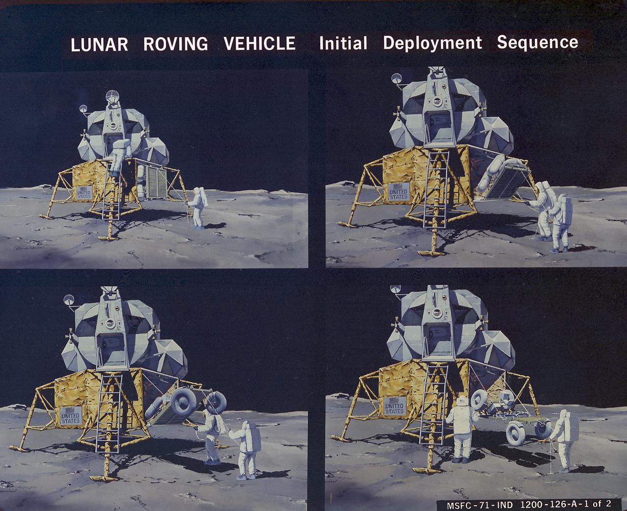
This artist's concept illustrates the deployment sequence of the Lunar Roving Vehicle (LRV) on the Moon. The LRV was designed to transport astronauts and materials on the Moon. It was a collapsible open-space vehicle about 10 feet long with large mesh wheels, anterna, appendages, tool caddies, and cameras. Powered by two 36-volt batteries, it has four 1/4-hp drive motors, one for each wheel. The vehicle was designed to travel in forward or reverse, negotiate obstacles about 1 foot high, cross crevasses about 2 feet wide, and climb or descend moderate slopes. Its speed limit was about 9 miles (14 kilometers) per hour. An LRV was used on each of the last three Apollo missions (Apollo 15, Apollo 16, and Apollo 17) and permitted the crew to travel several miles from the Lunar Module. The LRV was designed, developed, and tested by the Marshall Space Flight Center, and built by the Boeing Plant in Kent, Washington.
This artist's concept illustrates the deployment sequence of the Lunar Roving Vehicle (LRV) on the Moon. The LRV was designed to transport astronauts and materials on the Moon. It was a collapsible open-space vehicle about 10 feet long with large mesh wheels, anterna, appendages, tool caddies, and cameras. Powered by two 36-volt batteries, it has four 1/4-hp drive motors, one for each wheel. The vehicle was designed to travel in forward or reverse, negotiate obstacles about 1 foot high, cross crevasses about 2 feet wide, and climb or descend moderate slopes. Its speed limit was about 9 miles (14 kilometers) per hour. An LRV was used on each of the last three Apollo missions (Apollo 15, Apollo 16, and Apollo 17) and permitted the crew to travel several miles from the Lunar Module. The LRV was designed, developed, and tested by the Marshall Space Flight Center, and built by the Boeing Plant in Kent, Washington.
AS15-86-11601 (31 July 1971) --- Astronaut James B. Irwin, lunar module pilot, works at the Lunar Roving Vehicle (LRV) during the first Apollo 15 lunar surface extravehicular activity (EVA) at the Hadley-Apennine landing site. The Lunar Module (LM) "Falcon" is on the left. The undeployed Laser Ranging Retro Reflector (LR-3) lies atop the LM's modular equipment stowage assembly (MESA). This view is looking slightly west of south. Hadley Delta and the Apennine Front are in the background to the left. St. George crater is approximately five kilometers (about three statute miles) in the distance behind Irwin's head. This photograph was taken by astronaut David R. Scott, commander. While astronauts Scott and Irwin descended in the LM to explore the moon, astronaut Alfred M. Worden, command module pilot, remained with the Command and Service Modules (CSM) in lunar orbit.
S71-30542 (21 April 1971) --- An overall view of the Apollo 15 Lunar Roving Vehicle (LRV) and the Lunar Module (LM) during simulations at the Kennedy Space Center (KSC). Astronauts David R. Scott, commander, and James B. Irwin, lunar module pilot, will man the LRV on the lunar surface during their August 1971 traverses. Rover 1 will permit the astronauts to cover a larger area of the moon for exploration and sample collecting than on previous missions.
S72-30695 (22 Dec. 1971) --- Astronauts John W. Young, right, Apollo 16 commander, and Charles M. Duke Jr., lunar module pilot, maneuver a training version of the Lunar Roving Vehicle (LRV) about a field at Kennedy Space Center (KSC) simulated to represent the lunar surface. The LRV is planned to transport the two crew men around the Descartes area on the lunar surface while astronaut Thomas K. Mattingly II, command module pilot, orbits the moon in the Command and Service Modules (CSM).
AS17-146-22296 (13 Dec. 1972) --- Astronaut Harrison H. Schmitt, lunar module pilot, works near the Lunar Roving Vehicle (LRV) during the third Apollo 17 extravehicular activity (EVA) at the Taurus-Littrow site on the lunar surface. The front part of the LRV is out of frame at left, but the seats and several geological tools can be seen. The photo was taken by astronaut Eugene A. Cernan, mission commander.
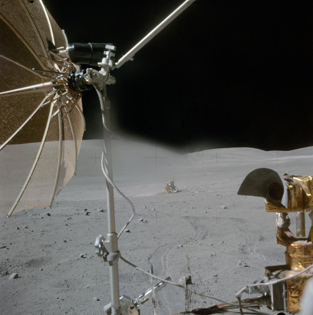
AS16-115-18549 (22 April 1972) --- The Apollo 16 Lunar Module (LM) "Orion" is photographed from a distance by astronaut Charles M. Duke Jr., lunar module pilot, aboard the moving Lunar Roving Vehicle (LRV). Astronauts Duke and John W. Young, commander, were returning from their excursion to Stone Mountain during the second Apollo 16 extravehicular activity (EVA). The RCA color television camera mounted on the LRV is in the foreground. A portion of the LRV's high-gain antenna is at top left. Smoky Mountain rises behind the LM in this north-looking view at the Descartes landing site. While astronauts Young and Duke descended in the "Orion" to explore the Descartes highlands landing site on the moon, astronaut Thomas K. Mattingly II, command module pilot, remained with the Command and Service Modules (CSM) "Casper" in lunar orbit.
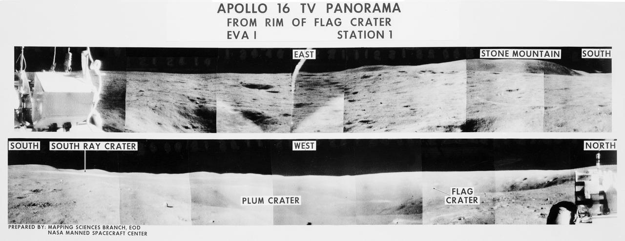
S72-35970 (21 April 1972) --- A 360-degree field of view of the Apollo 16 Descartes landing site area composed of individual scenes taken from color transmission made by the color RCA TV camera mounted on the Lunar Roving Vehicle (LRV). This panorama was made while the LRV was parked at the rim of Flag Crater (Station 1) during the first Apollo 16 lunar surface extravehicular activity (EVA) by astronauts John W. Young and Charles M. Duke Jr. The overlay identifies the directions and the key lunar terrain features. The camera panned across the rear portion of the LRV in its 360-degree sweep. Astronauts Young, commander; and Duke, lunar module pilot; descended in the Apollo 16 Lunar Module (LM) "Orion" to explore the Descartes highlands landing site on the moon. Astronaut Thomas K. Mattingly II, command module pilot, remained with the Command and Service Modules (CSM) "Casper" in lunar orbit.
AS16-116-18678 (23 April 1972) --- A view from the moving Apollo 16 Lunar Roving Vehicle (LRV) as the crew men headed "home" at the end of the mission's third and final extravehicular activity (EVA). Astronaut John W. Young called attention to the series of block fields between the Lunar Module (LM) and LRV. Young also noted that, "The LM was obviously sitting in the only flat place around." Stone Mountain stretches about half way across the background. The high gain antenna and the RCA television camera on the LRV are in the foreground. While astronauts Young, commander; and Charles M. Duke Jr., lunar module pilot; descended in the Apollo 16 LM "Orion" to explore the Descartes highlands landing site on the moon, astronaut Thomas K. Mattingly II, command module pilot, remained with the Command and Service Modules (CSM) "Casper" in lunar orbit.
AS17-147-22526 (11 Dec. 1972) --- Astronaut Eugene A. Cernan, commander, makes a short checkout of the Lunar Roving Vehicle (LRV) during the early part of the first Apollo 17 extravehicular activity (EVA) at the Taurus-Littrow landing site. This view of the "stripped down" LRV is prior to loading up. Equipment later loaded onto the LRV included the ground-controlled television assembly, the lunar communications relay unit, hi-gain antenna, low-gain antenna, aft tool pallet, lunar tools and scientific gear. This photograph was taken by scientist-astronaut Harrison H. Schmitt, lunar module pilot. The mountain in the right background is the east end of South Massif. While astronauts Cernan and Schmitt descended in the Lunar Module (LM) "Challenger" to explore the moon, astronaut Ronald E. Evans, command module pilot, remained with the Command and Service Modules (CSM) "America" in lunar orbit.
AS17-146-22367 (7-19 Dec. 1972) --- This is an excellent view of the Lunar Roving Vehicle (LRV) which was used extensively by astronauts Eugene A. Cernan and Harrison H. Schmitt at the Taurus-Littrow landing site.
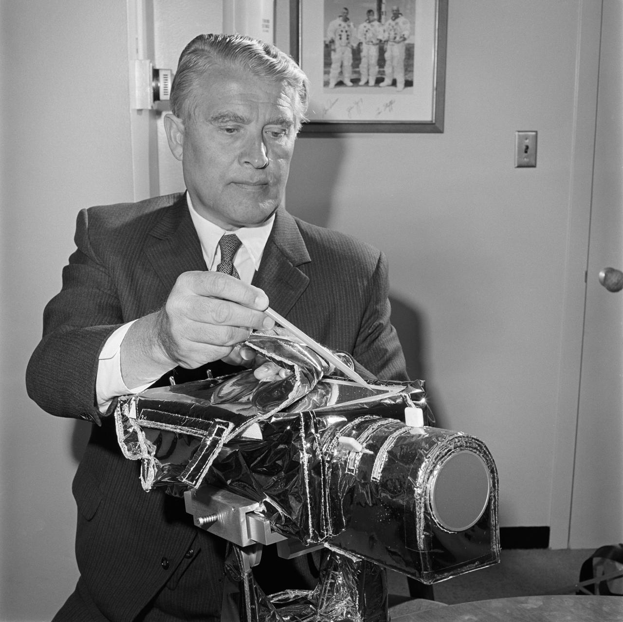
S71-35169 (June 1971) --- The color television camera for the National Aeronautics and Space Administration's (NASA) Apollo 15 lunar landing mission is examined by NASA's Deputy Associate Director Dr. Wernher von Braun. The camera will be mounted on the Lunar Roving Vehicle (LRV) and will be operated by the flight crew astronauts, David R. Scott and James B. Irwin, or by ground command from the Mission Control Center (MCC) in Houston during the three lunar traverses. It will also be used to show the astronauts whenever they leave the LRV, and for the first time it will make possible the viewing of the Lunar Module (LM) ascent stage as it lifts off the moon.

AS16-107-17436 (21 April 1972) --- An excellent view of the Lunar Module (LM) "Orion" and Lunar Roving Vehicle (LRV), as photographed by astronaut Charles M. Duke Jr., lunar module pilot, during the first Apollo 16 extravehicular activity (EVA) at the Descartes landing site. Astronaut John W. Young, commander, can be seen directly behind the LRV. The lunar surface feature in the left background is Stone Mountain. While astronauts Young and Duke descended in the LM to explore the Descartes highlands landing site on the moon, astronaut Thomas K. Mattingly II, command module pilot, remained with the Command and Service Modules (CSM) "Casper" in lunar orbit.
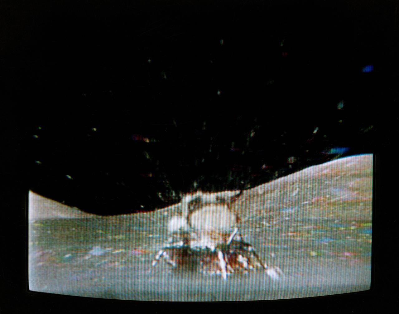
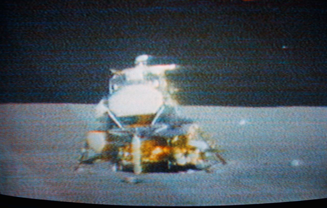
The Apollo 17 Lunar Module (LM) "Challenger" ascent stage leaves the Taurus-Littrow landing site as it makes its spectacular liftoff from the lunar surface, as seen in this reproduction taken from a color television transmission made by the color RCA TV camera mounted on the Lunar Roving Vehicle (LRV). The LRV-mounted TV camera, remotely controlled from the Mission Control Center (MCC) in Houston, made it possible for people on Earth to watch the fantastic event. The LM liftoff was at 188:01:36 ground elapsed time, 4:54:36 p.m. (CST), Thursday, December 14, 1972.
S71-41511 (2 Aug. 1971) --- The Apollo 15 Lunar Module (LM) "Falcon" is seen only seconds before ascent stage liftoff in this color reproduction taken from a transmission made by the RCA color television camera mounted on the Lunar Roving Vehicle (LRV). The LRV was parked about 300 feet east of the LM. The LRV-mounted TV camera, remotely controlled from the Mission Control Center (MCC), made it possible for people on Earth to watch the LM's launch from the moon. The LM liftoff was at 171:37 ground elapsed time. The "Falcon" ascent stage, with astronauts David R. Scott, commander; and James B. Irwin, lunar module pilot, aboard, returned from the lunar surface to rejoin the Command and Service Modules (CSM) orbiting the moon. Astronaut Alfred M. Worden, command module pilot, remained with the CSM in lunar orbit while Scott and Irwin explored the moon. The LM descent stage is used as a launching platform and remains behind on the moon. This is part one of a four-part sequence.
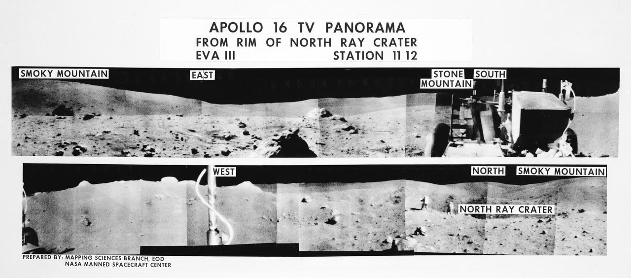
S72-35971 (21 April 1972) --- A 360-degree field of view of the Apollo 16 Descartes landing site area composed of individual scenes taken from color transmission made by the color RCA TV camera mounted on the Lunar Roving Vehicle (LRV). This panorama was made while the LRV was parked at the rim of North Ray Crater (Stations 11 & 12) during the third Apollo 16 lunar surface extravehicular activity (EVA) by astronauts John W. Young and Charles M. Duke Jr. The overlay identifies the directions and the key lunar terrain features. The camera panned across the rear portion of the LRV in its 360-degree sweep. Note Young and Duke walking along the edge of the crater in one of the scenes. The TV camera was remotely controlled from a console in the Mission Control Center (MCC). Astronauts Young, commander; and Duke, lunar module pilot; descended in the Apollo 16 Lunar Module (LM) "Orion" to explore the Descartes highlands landing site on the moon. Astronaut Thomas K. Mattingly II, command module pilot, remained with the Command and Service Modules (CSM) "Casper" in lunar orbit.
AS17-140-21494 (13 Dec. 1972) --- This view shows the Lunar Roving Vehicle (LRV) parked by an outcrop of rocks by astronauts Eugene A. Cernan and Harrison H. (Jack) Schmitt during their visit to extravehicular activity Station 6 (Henry Crater).
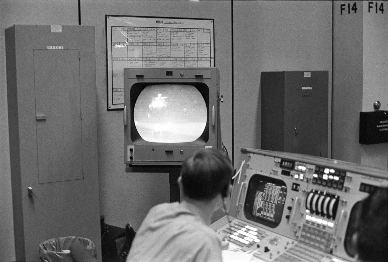
View of a photograph of the television (TV) monitor in the MCC showing a picture being transmitted from the color TV camera mounted on the parked Lunar Roving Vehicle (LRV) at the Hadley-Apennine Landing Site showing the liftoff of the Apollo 15 Lunar Module (LM) Ascent Stage from the Lunar surface. MSC, Houston, TX
AS17-145-22162 (7-19 Dec. 1972) --- One of the Apollo 17 crew photographed this view during lunar surface extravehicular activities (EVA) at the Taurus-Littrow landing site. The Lunar Rover Vehicle (LRV), which was used extensively by astronauts Eugene A. Cernan and Harrison H. Schmitt, is visible in the background.

Astronaut John W. Young, Apollo 16 prime crew commander (right), takes a drive in the One-G Lunar Roving Vehicle (LRV) trainer in the Lunar Topgraphic Simulation area at the Manned Spacecraft Center (MSC). He is accompanied by John Omstead, with General Electric, MSC.
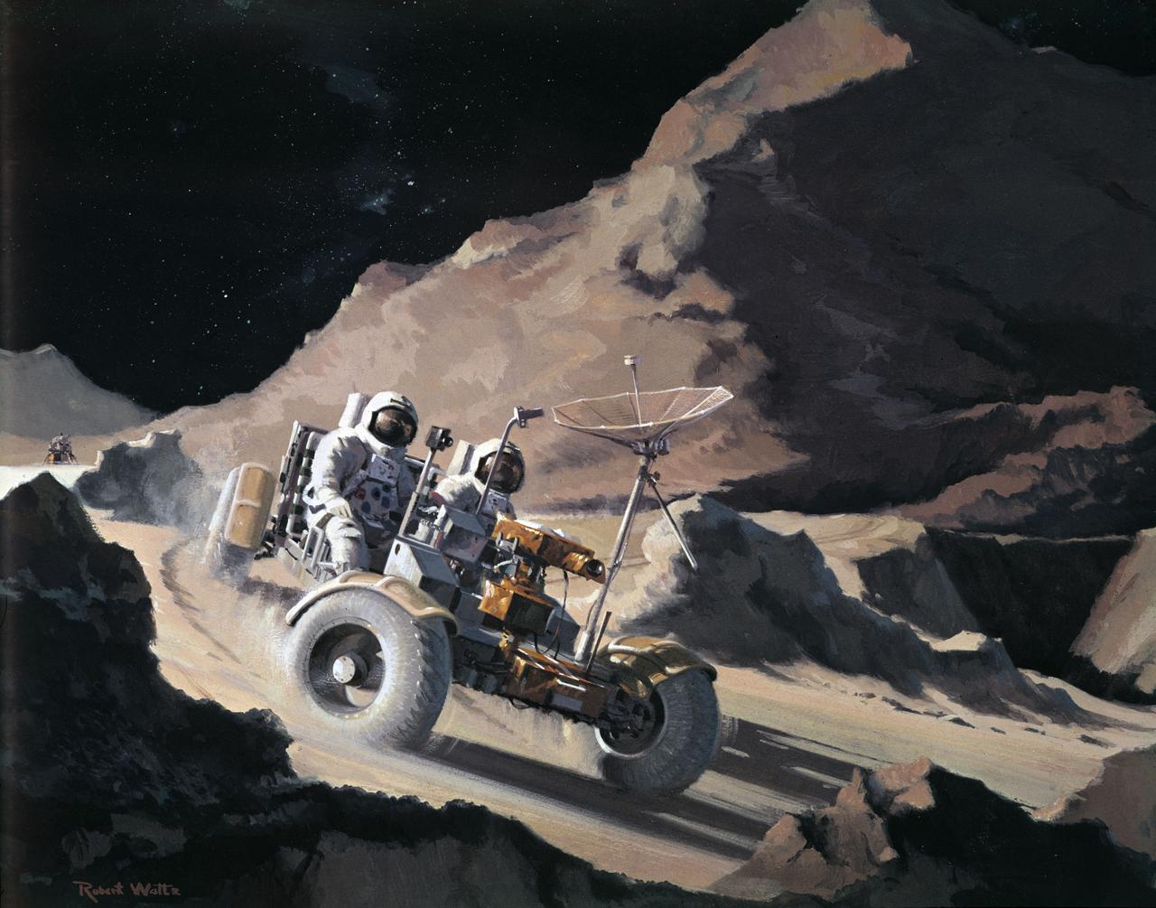
S71-39868 (July 1971) --- An artist's concept of the Apollo 15 Hadley-Apennine landing area showing the two moon-exploring crewmen on a traverse in their Lunar Roving Vehicle (LRV). The two figures represent astronauts David R. Scott, commander, and James B. Irwin, lunar module pilot. The artwork is by Teledyne Ryan.
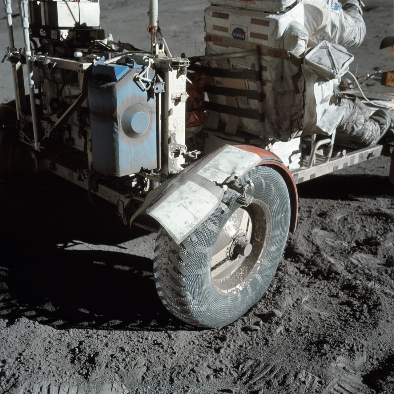
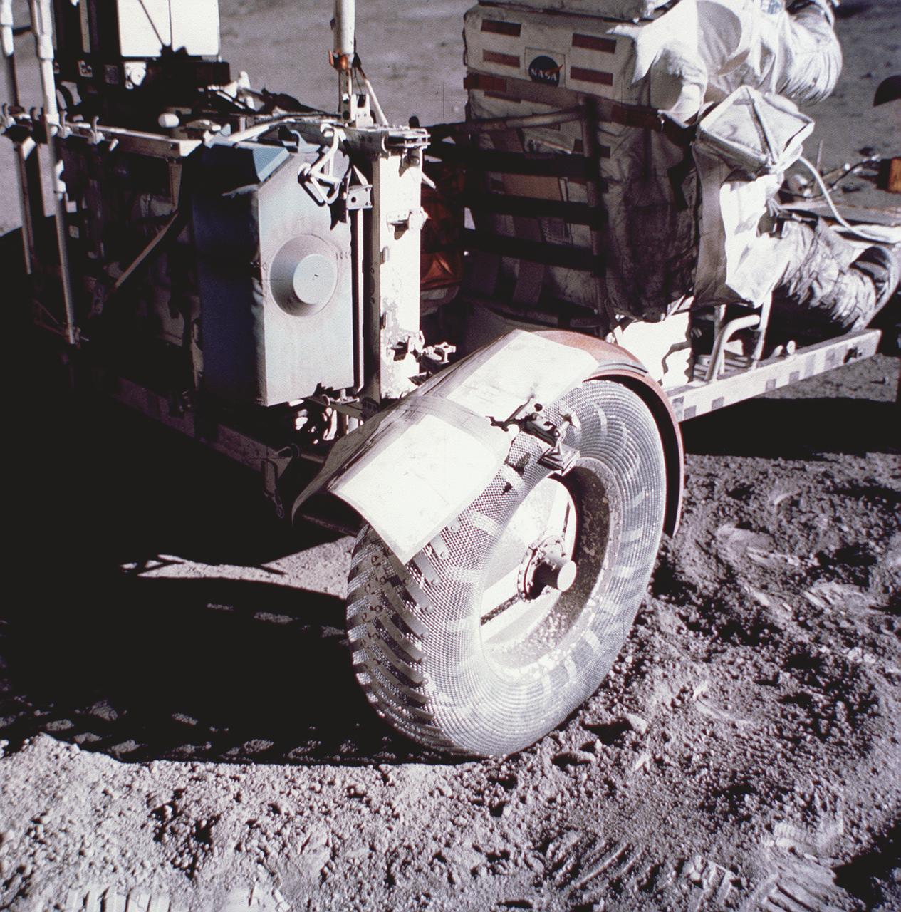
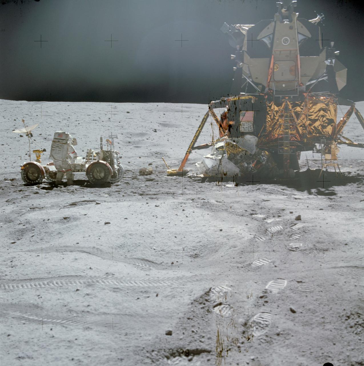
AS17-137-20979 (12 Dec. 1972) --- A close-up view of the lunar roving vehicle (LRV) at the Taurus-Littrow landing site photographed during Apollo 17 lunar surface extravehicular activity. Note the makeshift repair arrangement on the right rear fender of the LRV. During EVA-1 a hammer got underneath the fender and a part of it was knocked off. Astronauts Eugene A. Cernan and Harrison H. Schmitt were reporting a problem with lunar dust because of the damage fender. Following a suggestion from astronaut John W. Young in the Mission Control Center at Houston the crewmen repaired the fender early in EVA-2 using lunar maps and clamps from the optical alignment telescope lamp. Schmitt is seated in the rover. Cernan took this picture.