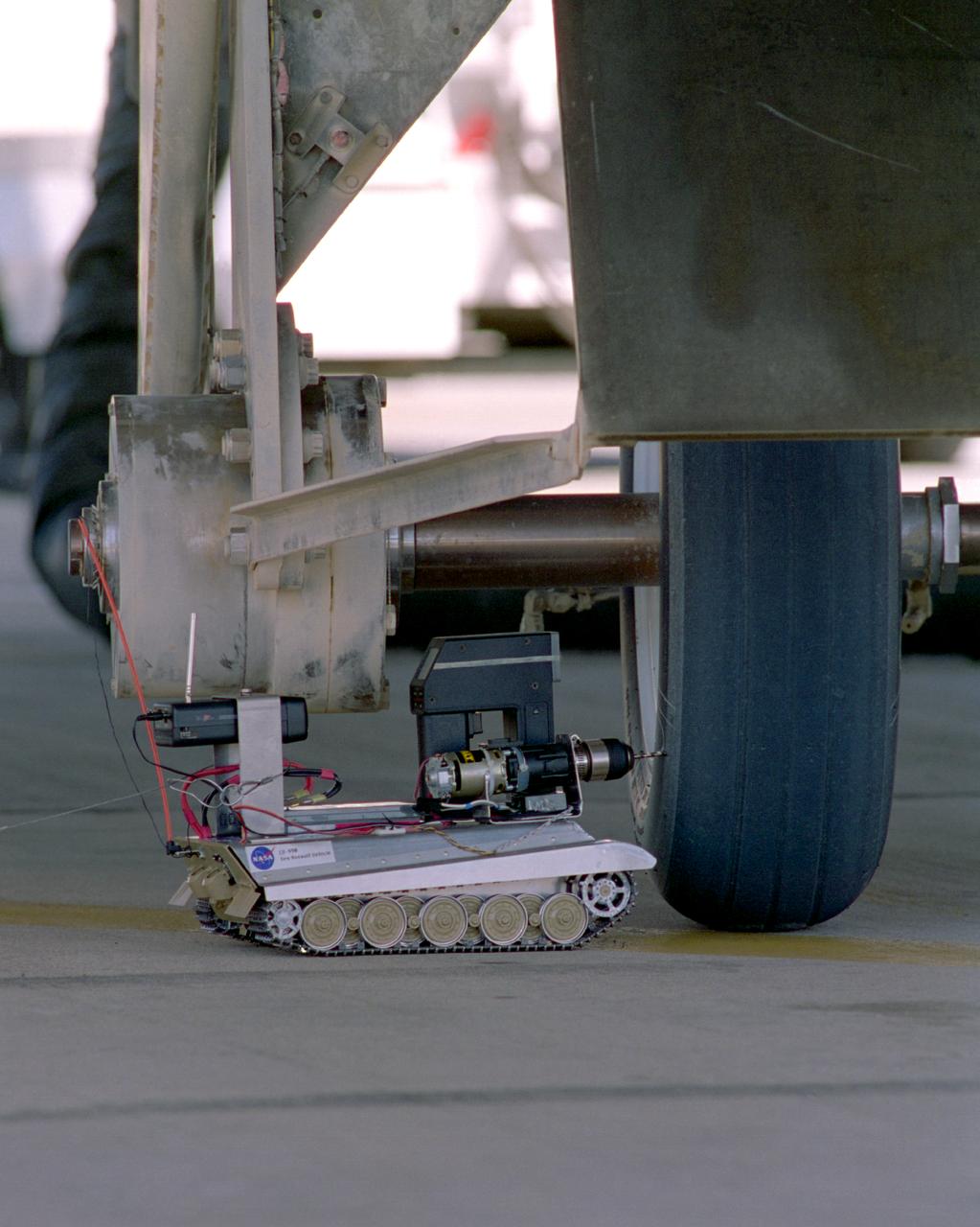
Created from a 1/16th model of a German World War II tank, the TAV (Tire Assault Vehicle) was an important safety feature for the Convair 990 Landing System Research Aircraft, which tested space shuttle tires. It was imperative to know the extreme conditions the shuttle tires could tolerate at landing without putting the shuttle and its crew at risk. In addition, the CV990 was able to land repeatedly to test the tires. The TAV was built from a kit and modified into a radio controlled, video-equipped machine to drill holes in aircraft test tires that were in imminent danger of exploding because of one or more conditions: high air pressure, high temperatures, and cord wear. An exploding test tire releases energy equivalent to two and one-half sticks of dynamite and can cause severe injuries to anyone within 50 ft. of the explosion, as well as ear injury - possibly permanent hearing loss - to anyone within 100 ft. The degree of danger is also determined by the temperature pressure and cord wear of a test tire. The TAV was developed by David Carrott, a PRC employee under contract to NASA.
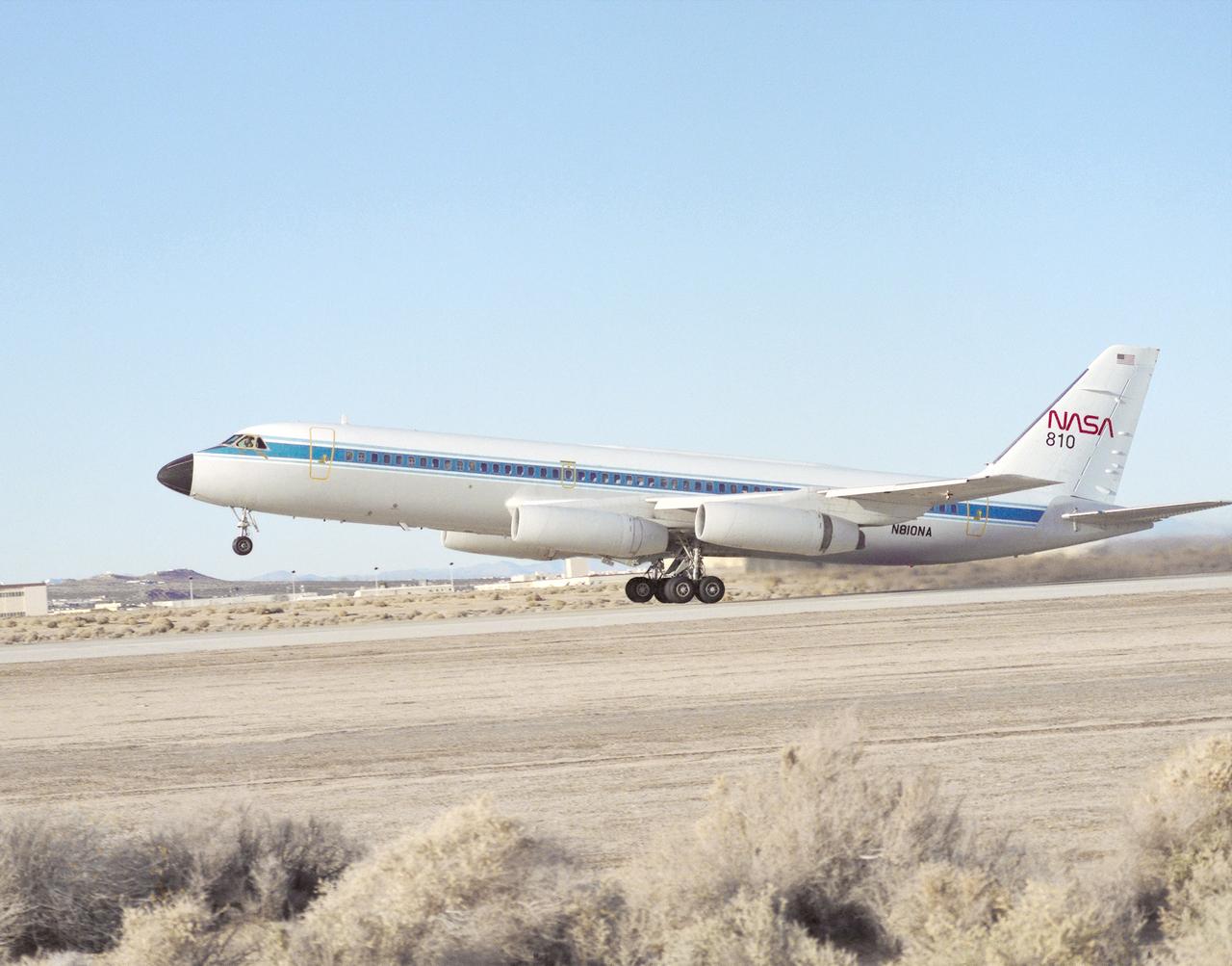
Taking off on a flight from NASA's Dryden Flight Research Center, Edwards, California, is NASA's Landing Systems Research Aircraft (LSRA), a modified Convair (CV) 990. A new landing gear test fixture representative of the shuttle's landing gear system had been installed in the lower fuselage of the CV-990 test aircraft between the aircraft's normal main landing gear. Following initial flights, static loads testing and calibration of the test gear were conducted at Dryden. Tests allowed engineers to assess the performance of the space shuttle's main and nose landing gear systems under varying conditions.
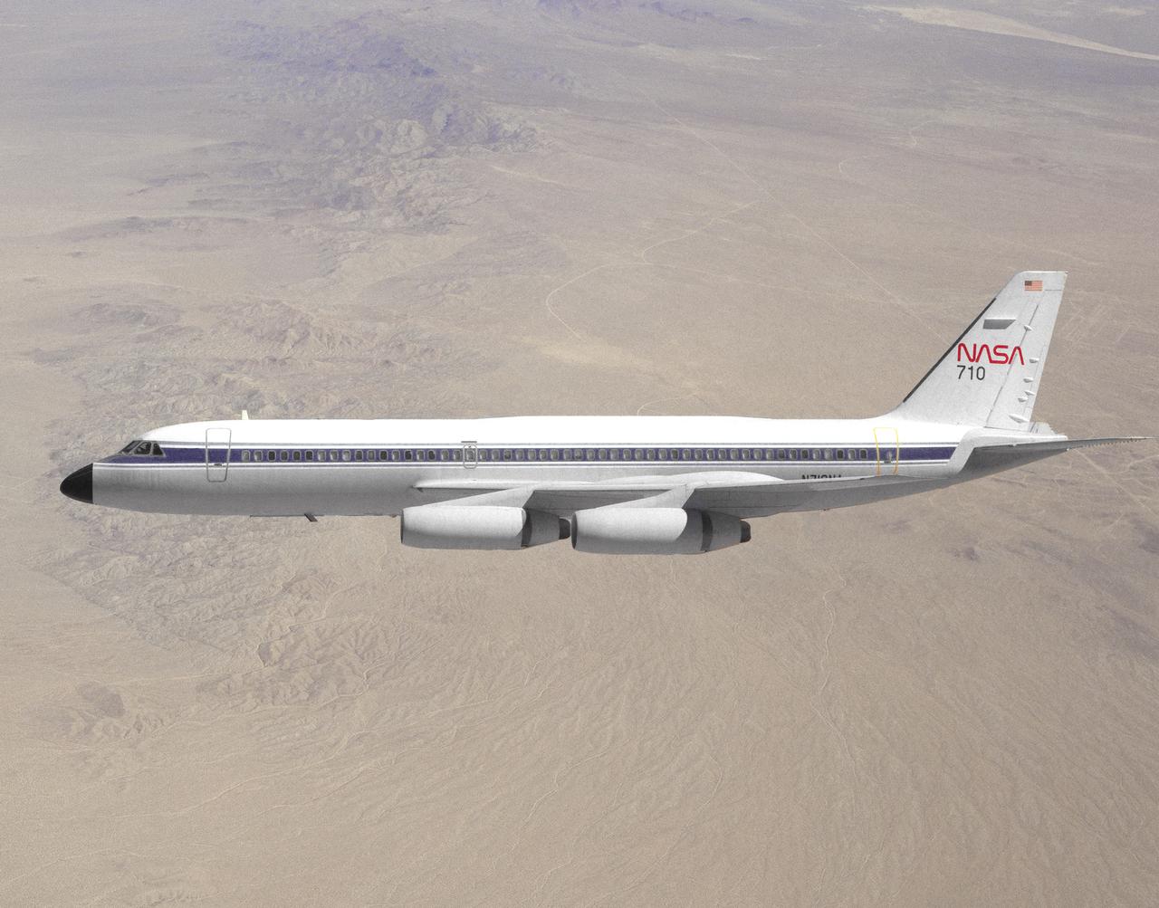
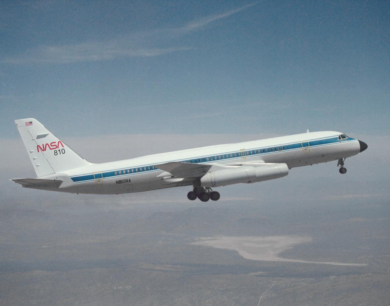
NASA 710, a Convair 990 transport aircraft formerly used for medium altitude atmospheric research, cruises over the Mojave Desert near NASA's Dryden Flight Research Center, Edwards, California. The flight was a final speed calibration run prior to the start of extensive modifications that turned the aircraft into a landing systems research aircraft to test and evaluate brakes and landing gear systems on space shuttles and also conventional aircraft. Research flights with the aircraft began in April of 1993. Testing of shuttle components lasted into fiscal year 1995.
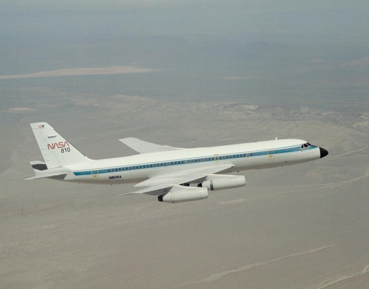
A NASA CV-990, modified as a Landing Systems Research Aircraft (LSRA), in flight over NASA's Dryden Flight Research Center, Edwards, California, for a test of the space shuttle landing gear system. The space shuttle landing gear test unit, operated by a high-pressure hydraulic system, allowed engineers to assess and document the performance of space shuttle main and nose landing gear systems, tires and wheel assemblies, plus braking and nose wheel steering performance. The series of 155 test missions for the space shuttle program provided extensive data about the life and endurance of the shuttle tire systems and helped raise the shuttle crosswind landing limits at Kennedy.
A NASA CV-990, modified as a Landing Systems Research Aircraft (LSRA), in flight over NASA's Dryden Flight Research Center, Edwards, California, for a test of the space shuttle landing gear system. The space shuttle landing gear test unit, operated by a high-pressure hydraulic system, allowed engineers to assess and document the performance of space shuttle main and nose landing gear systems, tires and wheel assemblies, plus braking and nose wheel steering performance. The series of 155 test missions for the space shuttle program provided extensive data about the life and endurance of the shuttle tire systems and helped raise the shuttle crosswind landing limits at Kennedy.
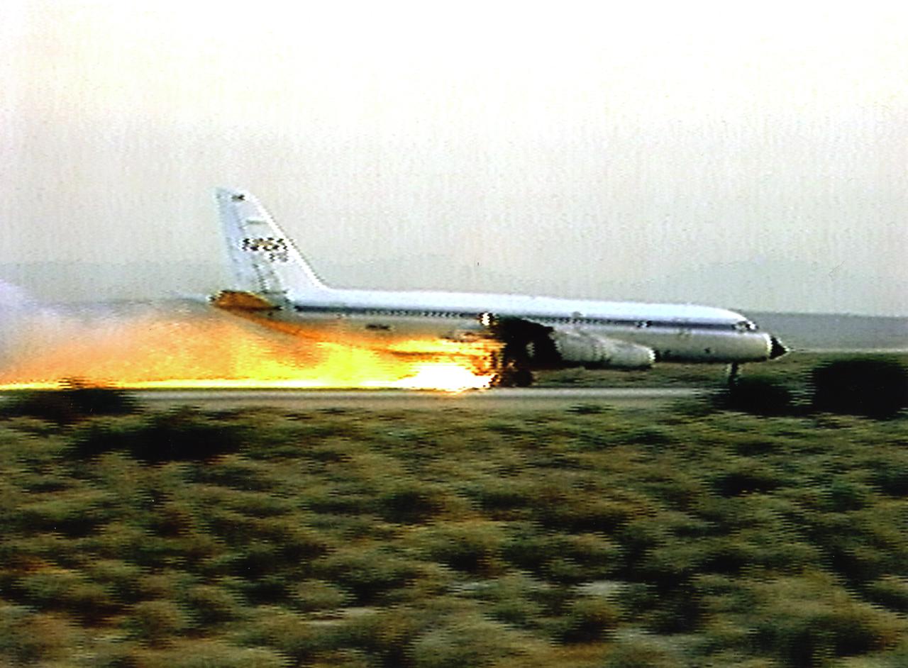
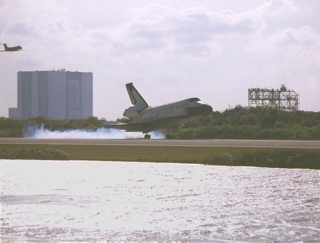
A NASA CV-990, modified as a Landing Systems Research Aircraft (LSRA), lands on the Edwards AFB main runway in test of the space shuttle landing gear system. In this case, the shuttle tire failed, bursting into flame during the rollout. The space shuttle landing gear test unit, operated by a high-pressure hydraulic system, allowed engineers to assess and document the performance of space shuttle main and nose landing gear systems, tires and wheel assemblies, plus braking and nose wheel steering performance. The series of 155 test missions for the space shuttle program provided extensive data about the life and endurance of the shuttle tire systems and helped raise the shuttle crosswind landing limits at Kennedy. The CV-990 used as the LSRA was built in 1962 by the Convair Division of General Dynamics Corp., Ft. Worth, Texas, served as a research aircraft at Ames Research Center, Moffett Field, California, before it came to Dryden.
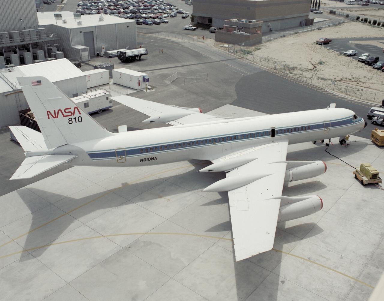
A NASA CV-990, modified as a Landing Systems Research Aircraft (LSRA), is serviced on the ramp at NASA's Dryden Flight Research Center, Edwards, California, before a test of the space shuttle landing gear system. The space shuttle landing gear test unit, operated by a high-pressure hydraulic system, allowed engineers to assess and document the performance of space shuttle main and nose landing gear systems, tires and wheel assemblies, plus braking and nose wheel steering performance. The series of 155 test missions for the space shuttle program provided extensive data about the life and endurance of the shuttle tire systems and helped raise the shuttle crosswind landing limits at Kennedy.
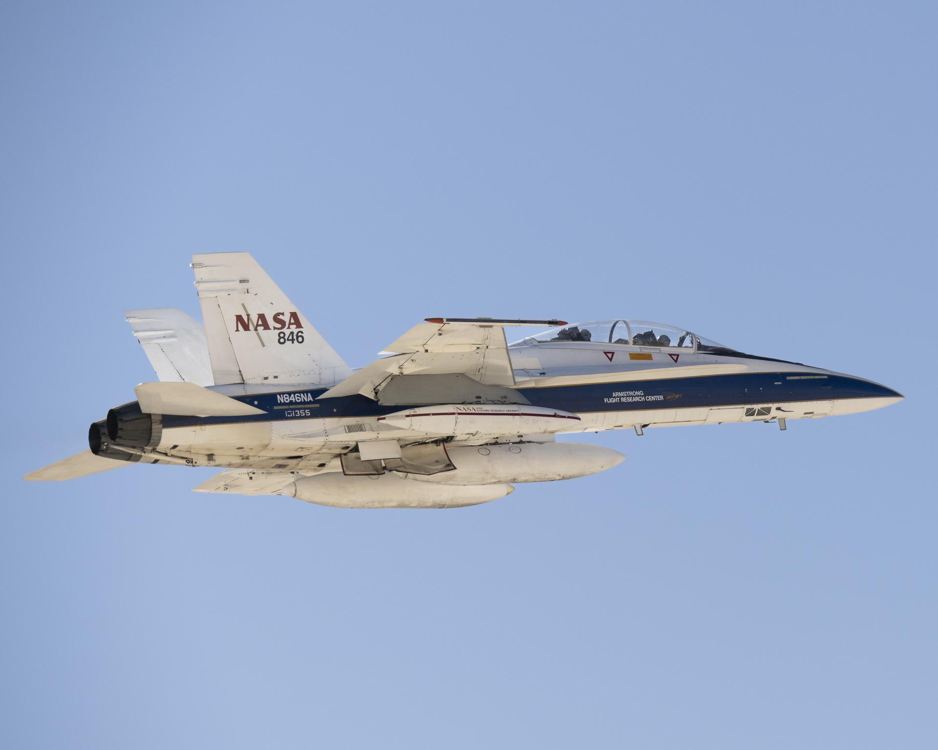
A NASA F/A-18 research aircraft flies near NASA’s Armstrong Flight Research Center in Edwards, California, on Feb. 24, 2025, testing a commercial precision landing technology for future space missions. The Psionic Space Navigation Doppler Lidar (PSNDL) system is installed in a pod located under the right wing of the aircraft.
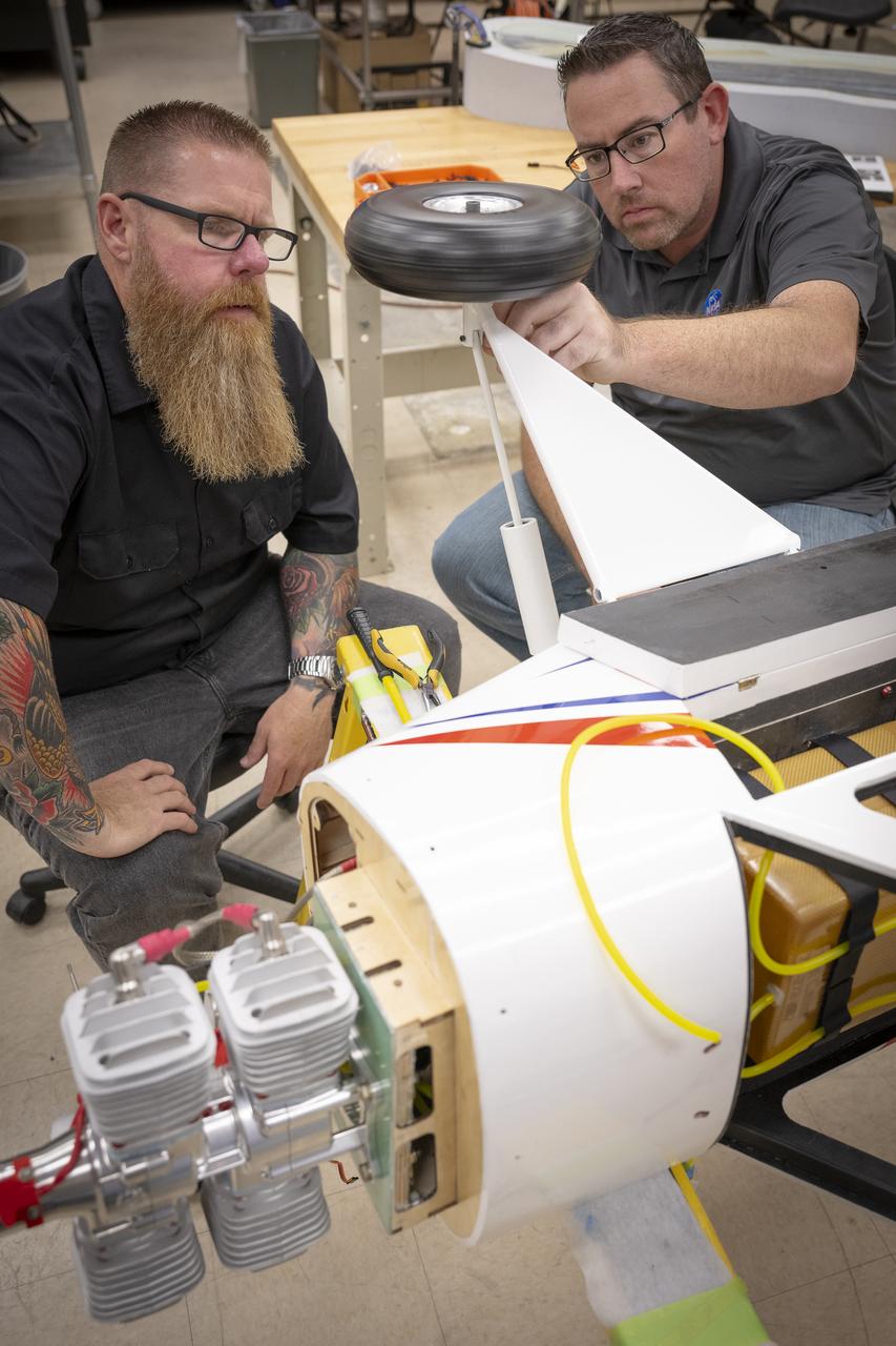
Justin Hall, left, and Justin Link attach a section of landing gear onto a subscale aircraft on Friday, Sept. 12, 2025, at NASA’s Armstong Flight Research Center in Edwards, California. Hall is chief pilot at the center’s Dale Reed Subscale Flight Research Laboratory and Link is a pilot for small uncrewed aircraft systems.
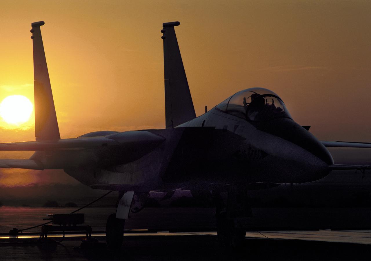
NASA's highly modified F-15A (Serial #71-0287) used for digital electronic flight and engine control systems research, at sunrise on the ramp at the Dryden Flight Research Facility, Edwards, California. The F-15 was called the HIDEC (Highly Integrated Digital Electronic Control) flight facility. Research programs flown on the testbed vehicle have demonstrated improved rates of climb, fuel savings, and engine thrust by optimizing systems performance. The aircraft also tested and evaluated a computerized self-repairing flight control system for the Air Force that detects damaged or failed flight control surfaces. The system then reconfigures undamaged control surfaces so the mission can continue or the aircraft is landed safely.
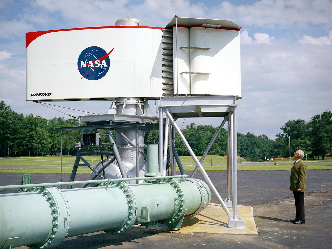
The augmentor wing concept was introduced during the early 1960s to enhance the performance of vertical and short takeoff (VSTOL) aircraft. The leading edge of the wing has full-span vertical flaps, and the trailing edge has double-slotted flaps. This provides aircraft with more control in takeoff and landing conditions. The augmentor wing also produced lower noise levels than other VSTOL designs. In the early 1970s Boeing Corporation built a Buffalo C-8A augmentor wing research aircraft for Ames Research Center. Researches at Lewis Research Center concentrated their efforts on reducing the noise levels of the wing. They initially used small-scale models to develop optimal nozzle screening methods. They then examined the nozzle designs on a large-scale model, seen here on an external test stand. This test stand included an airflow system, nozzle, the augmentor wing, and a muffler system below to reduce the atmospheric noise levels. The augmentor was lined with noise-reducing acoustic panels. The Lewis researchers were able to adjust the airflow to simulate conditions at takeoff and landing. Once the conditions were stabilized they took noise measurements from microphones placed in all directions from the wing, including an aircraft flying over. They found that the results coincided with the earlier small-scale studies for landing situations but not takeoffs. The acoustic panels were found to be successful.
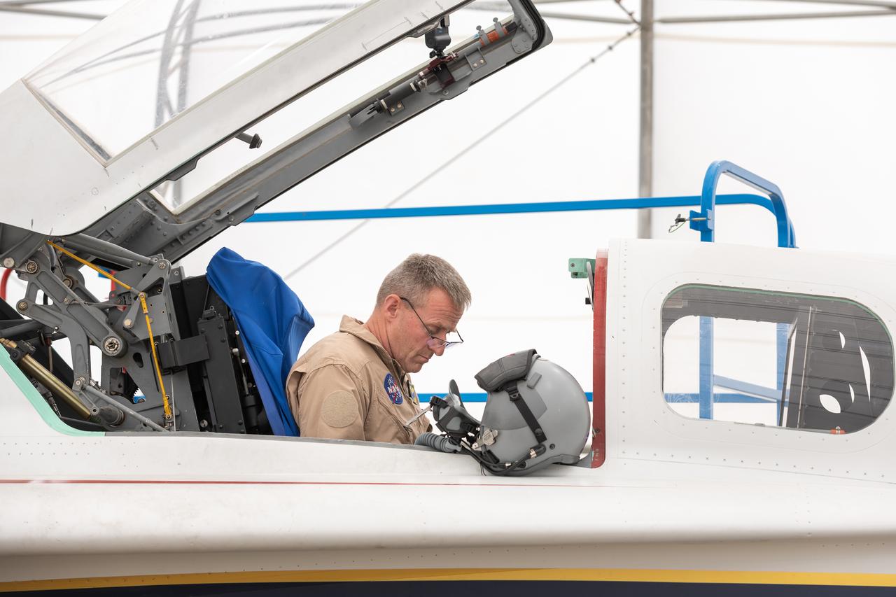
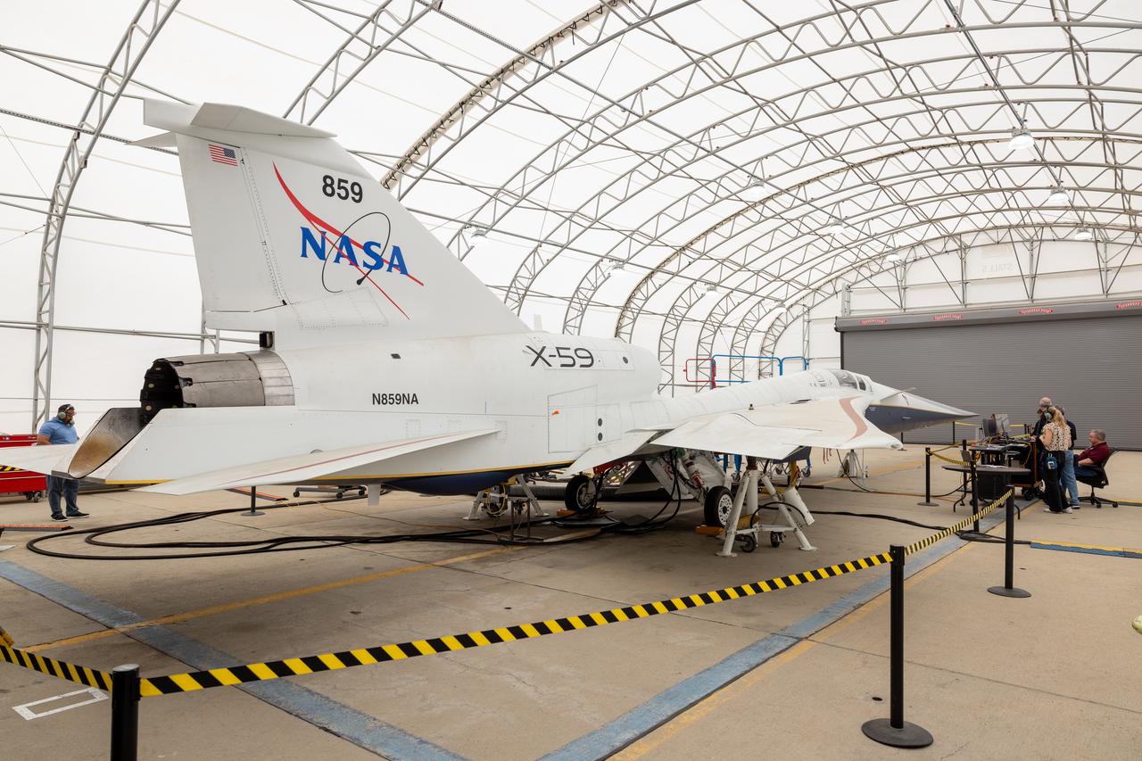
NASA’s X-59 quiet supersonic research aircraft successfully completed its “aluminum bird” systems test at Lockheed Martin’s Skunk Works facility in Palmdale, California. With NASA pilot James Less in the cockpit, the X-59 team simulated flight conditions from takeoff to landing – without ever leaving the ground. The test verified how the aircraft’s hardware and software work together, responding to pilot inputs and handling injected system failures. This milestone confirms the aircraft’s readiness for the next series of tests leading to first flight.
NASA’s X-59 quiet supersonic research aircraft successfully completed its “aluminum bird” systems test at Lockheed Martin’s Skunk Works facility in Palmdale, California. With NASA pilot James Less in the cockpit, the X-59 team simulated flight conditions from takeoff to landing – without ever leaving the ground. The test verified how the aircraft’s hardware and software work together, responding to pilot inputs and handling injected system failures. This milestone confirms the aircraft’s readiness for the next series of tests leading to first flight.
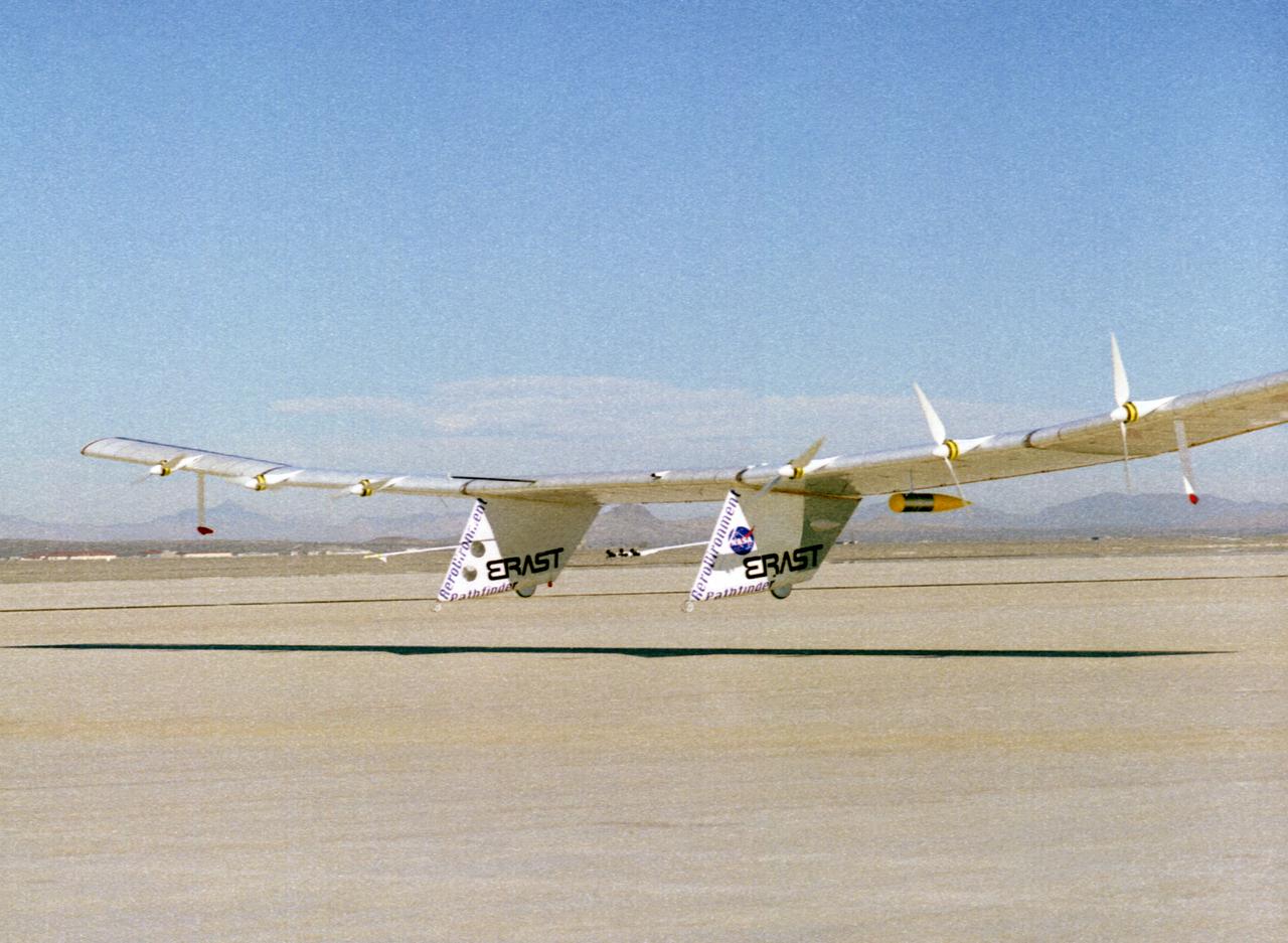
The Pathfinder solar-powered research aircraft settles in for landing on the bed of Rogers Dry Lake at the Dryden Flight Research Center, Edwards, California, after a successful test flight Nov. 19, 1996. The ultra-light craft flew a racetrack pattern at low altitudes over the flight test area for two hours while project engineers checked out various systems and sensors on the uninhabited aircraft. The Pathfinder was controlled by two pilots, one in a mobile control unit which followed the craft, the other in a stationary control station. Pathfinder, developed by AeroVironment, Inc., is one of several designs being evaluated under NASA's Environmental Research Aircraft and Sensor Technology (ERAST) program.
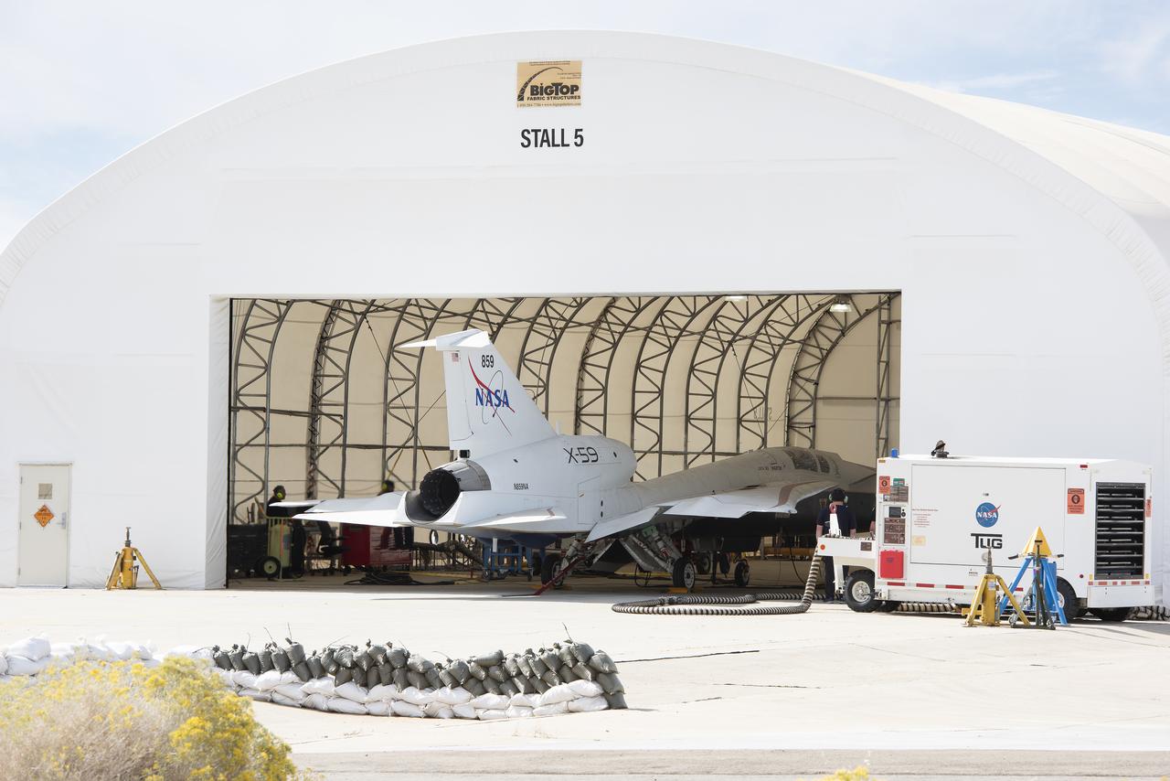
NASA’s X-59 quiet supersonic research aircraft sits in its run stall at Lockheed Martin’s Skunk Works facility in Palmdale, California, firing up its engine for the first time. These engine-run tests start at low power and allow the X-59 team to verify the aircraft’s systems are working together while powered by its own engine. The X-59 is the centerpiece of NASA’s Quesst mission, which seeks to solve one of the major barriers to supersonic flight over land by making sonic booms quieter.
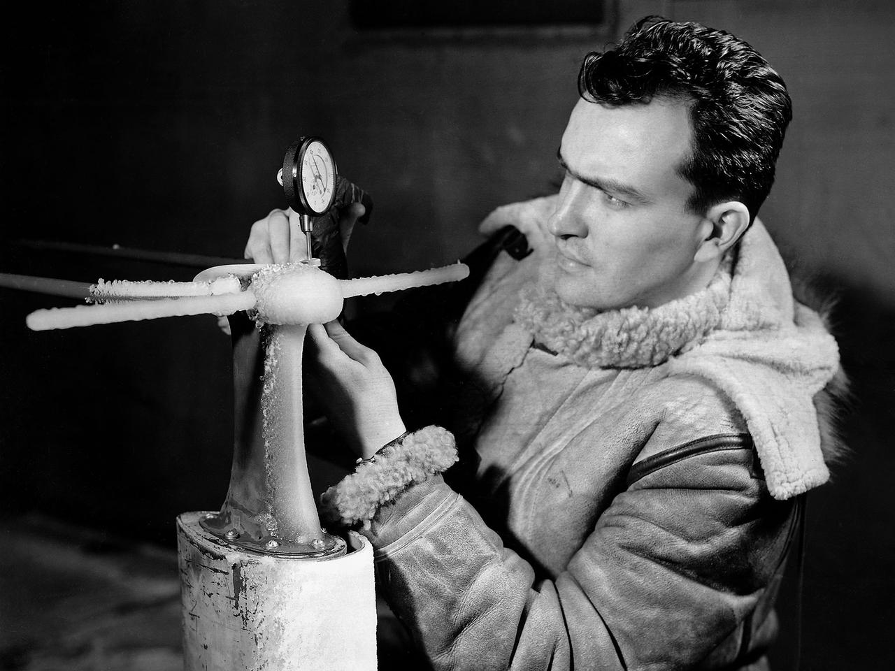
A National Advisory Committee for Aeronautics (NACA) researcher measures the ice thickness on a landing antenna model in the Icing Research Tunnel at the Aircraft Engine Research Laboratory. NACA design engineers added the Icing Research Tunnel to the original layout of the new Aircraft Engine Research Laboratory to take advantage of the massive refrigeration system being built for the Altitude Wind Tunnel. The Icing Research Tunnel was built to study the formation of ice on aircraft surfaces and methods of preventing or eradicating that ice. Ice buildup adds extra weight, effects aerodynamics, and sometimes blocks air flow through engines. The Icing Research Tunnel is a closed-loop atmospheric wind tunnel with a 6- by 9-foot test section. Carrier Corporation refrigeration equipment reduced the internal air temperature to -45 degrees F and a spray bar system injected water droplets into the air stream. The 24-foot diameter drive fan, seen in this photograph, created air flows velocities up to 400 miles per hour. The Icing Research Tunnel began testing in June of 1944. Early testing, seen in this photograph, studied ice accumulation on propellers and antenna of a military aircraft. The Icing Research Tunnel’s designers, however, struggled to develop a realistic spray system since they did not have access to data on the size of naturally occurring water droplets. The system would have to generate small droplets, distribute them uniformly throughout the airstream, and resist freezing and blockage. For five years a variety of different designs were painstakingly developed and tested before the system was perfected.
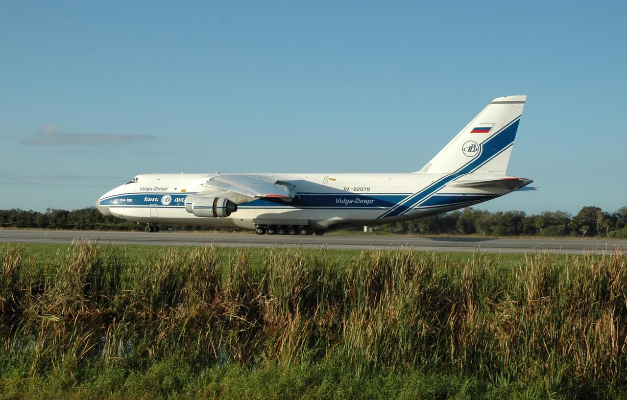
KENNEDY SPACE CENTER, FLA. -- At the KSC Shuttle Landing Facility, the Antonov 124 aircraft arrives with its cargo, the remote manipulator system for the Japanese Experiment Module. The JEM, named "Kibo" (Hope), is Japan's primary contribution to the International Space Station. It will enhance the unique research capabilities of the orbiting complex by providing an additional environment for astronauts to conduct science experiments. The Japanese Aerospace Exploration Agency developed the laboratory. Both the JEM and RMS are targeted for mission STS-124, to launch in early 2008. Photo credit: NASA/Jack Pfaller
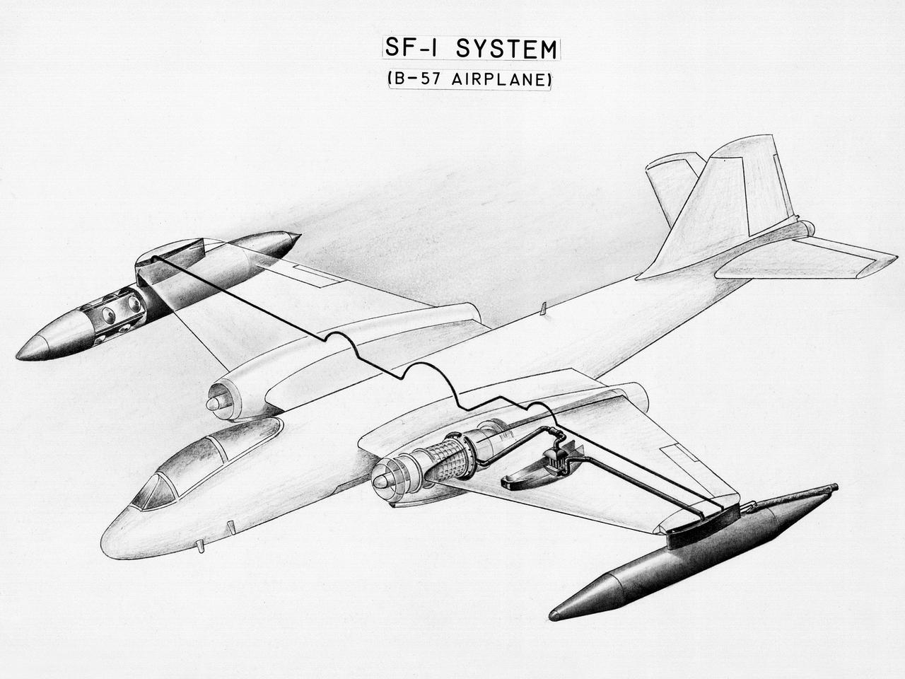
This diagram shows a hydrogen fuel system designed by researchers at the National Advisory Committee for Aeronautics (NACA) Lewis Flight Propulsion Laboratory and installed on a Martin B-57B Canberra aircraft. Lewis researchers accelerated their studies of high energy propellants in the early 1950s. In late 1954, Lewis researchers studied the combustion characteristics of gaseous hydrogen in a turbojet combustor. It was found that the hydrogen provided a very high efficiency. Almost immediately thereafter, Associate Director Abe Silverstein became focused on the possibilities of hydrogen for aircraft propulsion. That fall, Silverstein secured a contract to work with the air force to examine the practicality of liquid hydrogen aircraft. A B-57B Canberra was obtained by the air force especially for this project, referred to as Project Bee. The aircraft was powered by two Wright J65 engines, one of which was modified so that it could be operated using either traditional or liquid hydrogen propellants. The engine and its liquid hydrogen fuel system were tested extensively in the Altitude Wind Tunnel and the Four Burner Area test cells in 1955 and 1956. A B-57B flight program was planned to test the system on an actual aircraft. The aircraft would take off using jet fuel, switch to liquid hydrogen while over Lake Erie, then after burning the hydrogen supply switch back to jet fuel for the landing. The third test flight, in February 1957, was a success, and the ensuing B-57B flights remain the only demonstration of hydrogen-powered aircraft.
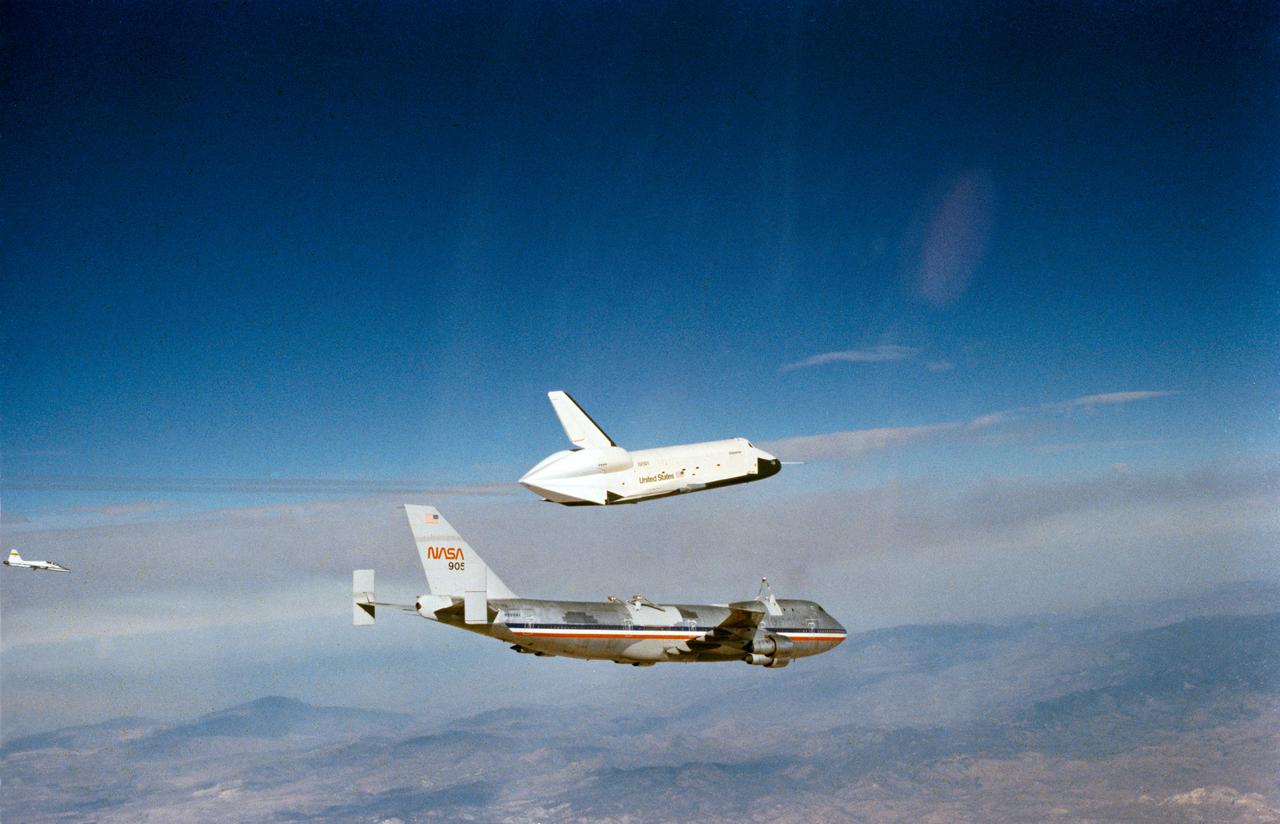
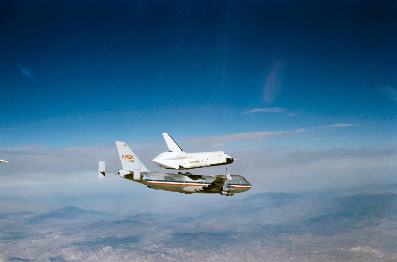
S77-28137 (13 Sept 1977) --- The Orbiter 101 "Enterprise" soars above the NASA 747 carrier aircraft during the second free flight of the Shuttle Approach and Landing Tests (ALTs) conducted on September 13, 1977 at Dryden Flight Research Center in Southern California. Astronauts Joe H. Engle, and Richard H. Truly were the crew of the "Enterprise." The ALT free flights are designed to verify Orbiter subsonic airworthiness, integrated systems operations and pilot-guided approach and landing capability and satisfying prerequisites to automatic flight control and navigation mode.
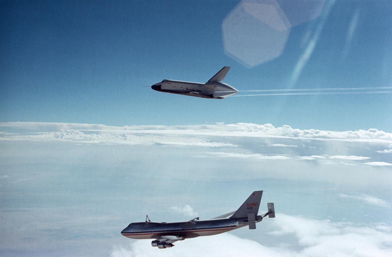
S77-27945 (12 Aug 1977) --- The space shuttle Orbiter 101 "Enterprise" soars above the NASA 747 carrier aircraft after separating during the first free flight of the Shuttle Approach and Landing Tests (ALTs) conducted on Aug. 12, 1977 at Dryden Flight Research Center in Southern California. Astronauts Fred W. Haise Jr., and C. Gordon Fullerton were the crew of the "Enterprise." The ALT free flights are designed to verify Orbiter subsonic airworthiness, integrated systems operations and pilot-guided approach and landing capability and satisfying prerequisites to automatic flight control and navigation mode. Photo credit: NASA
S77-28136 (13 Sept 1977) --- The Orbiter 101 "Enterprise" is seen separating from the NASA 747 carrier aircraft during the second free flight of the Shuttle Approach and Landing Tests (ALTs) conducted on September 13, 1977 at Dryden Flight Research Center in Southern California. Astronauts Joe H. Engle, and Richard H. Truly were the crew of the "Enterprise." The ALT free flights are designed to verify Orbiter subsonic airworthiness, integrated systems operations and pilot-guided approach and landing capability and satisfying prerequisites to automatic flight control and navigation mode.
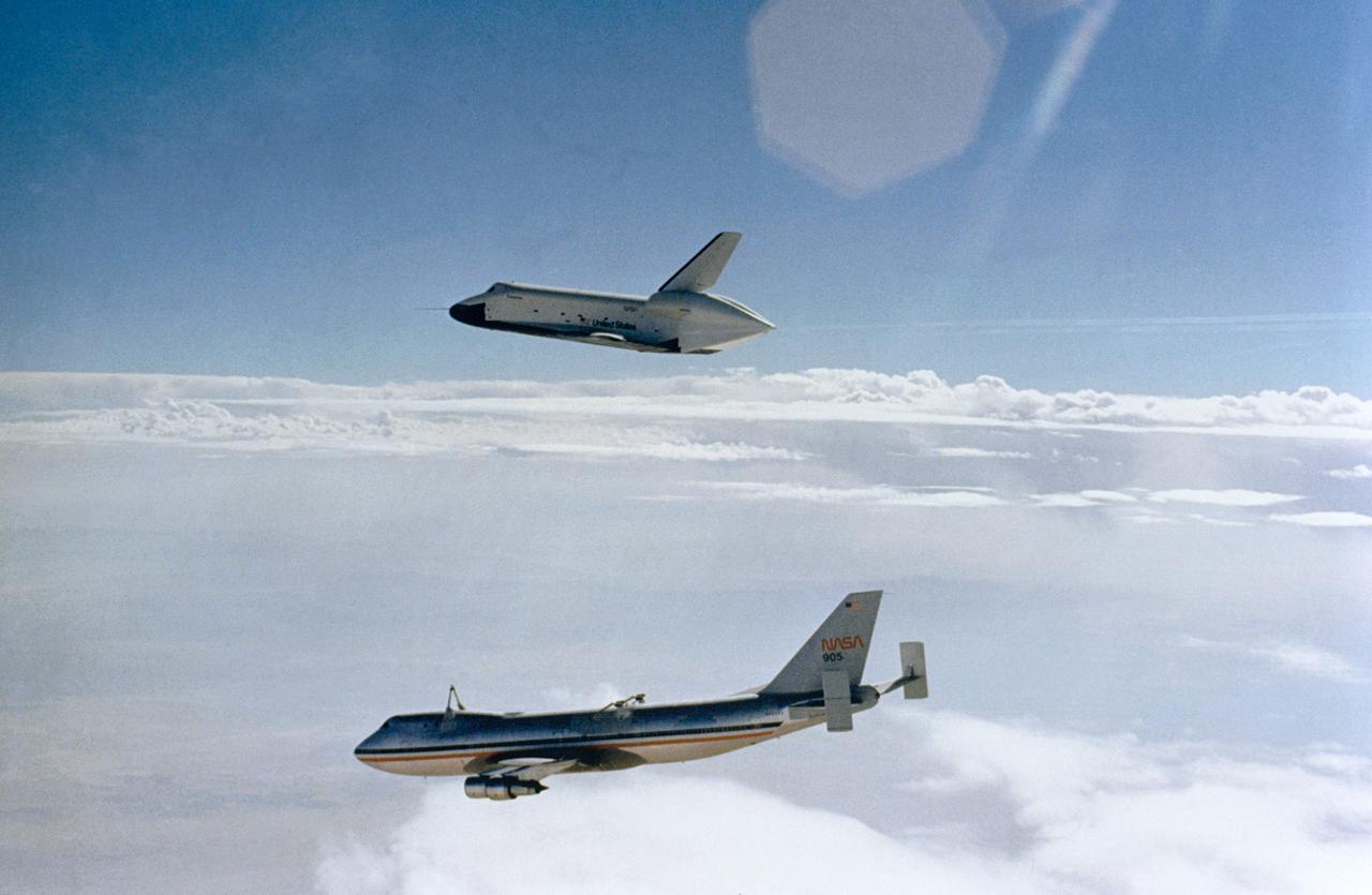
S77-27512 (12 Aug 1977) --- The Shuttle Orbiter 101 "Enterprise" soars above the NASA 747 carrier aircraft only seconds after separating during the first free flight of the Shuttle Approach and Landing Tests (ALTs) conducted on August 12, 1977 at Dryden Flight Research Center in Southern California. Astronauts Fred W. Haise Jr., and C. Gordon Fullerton were the crew of the "Enterprise." The ALT free flights are designed to verify Orbiter subsonic airworthiness, integrated systems operations and pilot-guided approach and landing capability and satisfying prerequisites to automatic flight control and navigation mode.
The US Air Force loaned a Republic F-84 Thunderjet to the National Advisory Committee for Aeronautics (NACA) Lewis Flight Propulsion Laboratory in the spring of 1954. NACA researchers soon modified the aircraft for the first demonstration of a reverse thruster. Republic built over 4000 Thunderjets between 1947 and 1953 for the military as a successor to the Lockheed F-80 Shooting Star. TheF-84s became successful multi-use aircraft during the Korean War. The use of traditional wheel brakes on high speed aircraft was problematic because the required braking system would weigh too much. The reverse thruster was developed as a method for stopping these aircraft without increasing the overall weight. Panels in the tail section near the jet engine’s nozzle opened up during a landing. These extended flaps not only caused resistance to the airstream but also reversed the engine’s thrust. In June 1964 Irving Pinkel, head of the Lewis Physics Division, oversaw a demonstration of this technology on an F-84 at the NACA laboratory. The side fuselage panels around the engine nozzle, seen closed in this photograph, opened up like wings and deflected the engine’s thrust towards the front of the aircraft, thus producing reverse thrust. The F-84 activated the reverse thruster and the aircraft moved backwards across the runway.
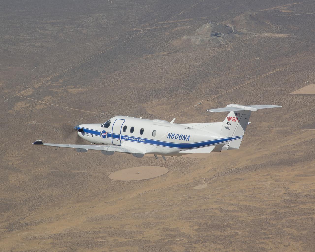
Equipped with state-of-the-art technology to test and evaluate communication, navigation, and surveillance systems, NASA’s Pilatus PC-12 flies over the Mojave Desert near Armstrong Flight Research Center in Edwards, California. Based at Glenn Research Center in Cleveland, the Pilatus PC-12 runs a series of familiarization flights for NASA Armstrong pilots before a test series evaluating ADS-B or Automatic Dependent Surveillance Broadcast systems for advanced air mobility applications in the desert flight test range on Sept. 18, 2024. Airborne work during familiarization flights includes several approach and landings, with an emphasis on avionics, then medium altitude air-work with steep turns, slow flight, and stall demonstrations to qualitatively understand the handling characteristics of the aircraft. The flights lasted about 60 to 90 minutes on average.
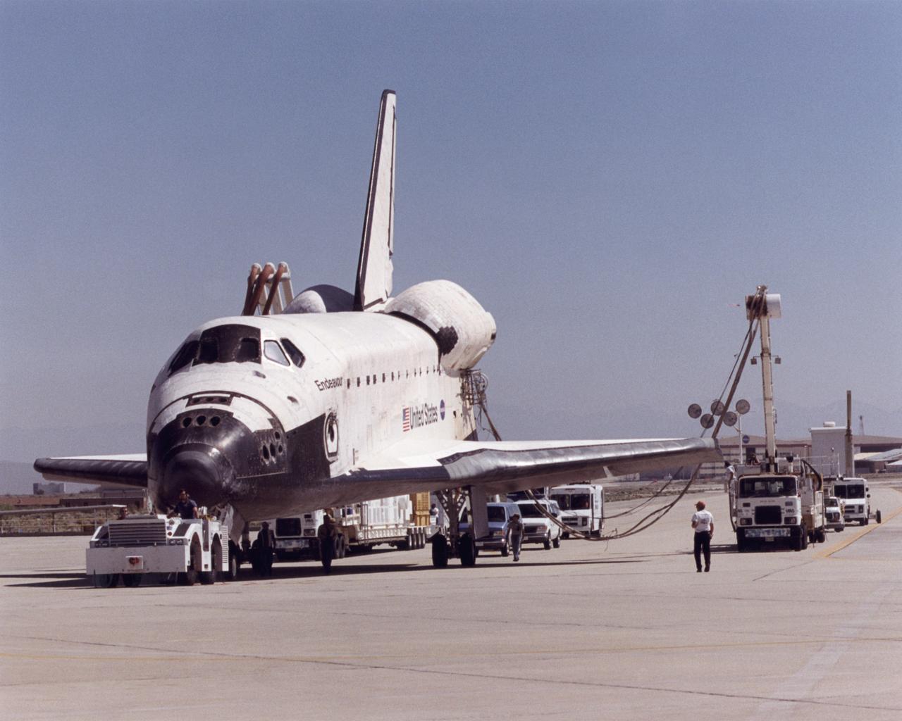
A convoy of specialized support vehicles follow the Space Shuttle Endeavour as it is towed up a taxiway at NASA's Dryden Flight Research Center on Edwards Air Force Base, California, after landing on May 1, 2001. The two largest vehicles trailing the shuttle provide electrical power and air conditioning to the shuttle's systems during post-flight recovery operations. The Endeavour had just completed mission STS-100, an almost 12-day mission to install the Canadarm 2 robotic arm and deliver some three tons of supplies and experiments to the International Space Station. The landing was the 48th shuttle landing at Edwards since shuttle flights began in 1981. After post-flight processing, the Endeavour was mounted atop one of NASA's modified Boeing 747 shuttle carrier aircraft and ferried back to the Kennedy Space Center in Florida on May 8, 2001.
S77-28138 (13 Sept 1977) --- The shuttle Orbiter 101 "Enterprise" makes a slight turn and bank maneuver during the second free flight of the Shuttle Approach and Landing Tests (ALT) conducted on September 13, 1977, at the Dryden Flight Research Center in Southern California. The "Enterprise" separated from the NASA 747 carrier aircraft and landed following a five-minute, 28-second unpowered flight. The Orbiter 101 crew was astronauts Joe H. Engle, commander, and Richard H. Truly, pilot. The ALT free flights are designed to verify orbiter subsonic airworthiness, integrated systems operations and pilot-guided approach and landing capability and satisfy prerequisites to automatic flight control and navigation mode. The orbiter soars above the dry California desert in this post-separation view. Astronaut C. Gordon Fullerton took this picture while riding in T-38 chase plane number one. He used a 35mm Nikon camera with a 50mm lens.
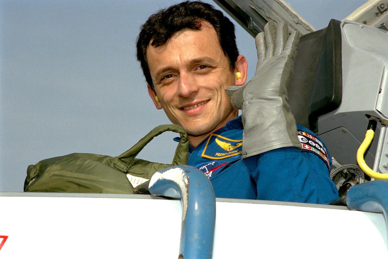
STS-95 Payload Specialist Pedro Duque of Spain, who represents the European Space Agency (ESA), waves after arriving in a T-38 jet aircraft at the Shuttle Landing Facility at KSC. He is joining other STS-95 crew members in a familiarization tour of the SPACEHAB module and the equipment that will fly with them on the Space Shuttle Discovery scheduled to launch Oct. 29, 1998. The mission includes research payloads such as the Spartan solar-observing deployable spacecraft, the Hubble Space Telescope Orbital Systems Test Platform, the International Extreme Ultraviolet Hitchhiker, as well as the SPACEHAB single module with experiments on space flight and the aging process
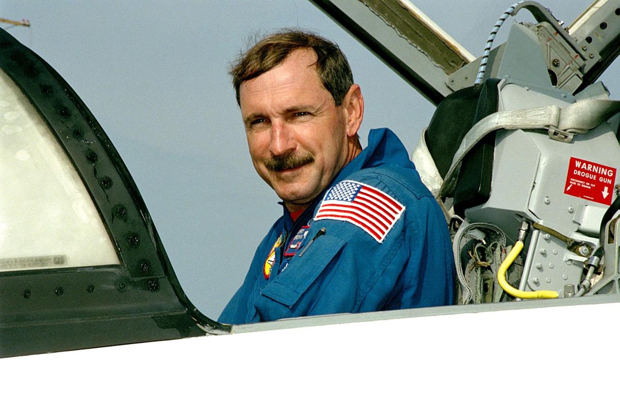
STS-95 Mission Commander Curtis L. Brown Jr. arrives aboard a T-38 jet aircraft at the Shuttle Landing Facility at KSC. The STS-95 crew is at KSC to look at the SPACEHAB module and the equipment that will fly with them on the Space Shuttle Discovery scheduled to launch Oct. 29, 1998. The mission includes research payloads such as the Spartan solar-observing deployable spacecraft, the Hubble Space Telescope Orbital Systems Test Platform, the International Extreme Ultraviolet Hitchhiker, as well as the SPACEHAB single module with experiments on space flight and the aging process
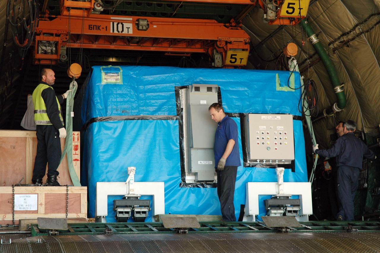
KENNEDY SPACE CENTER, FLA. -- At the KSC Shuttle Landing Facility, workers get ready to offload the newly arrived cargo of the Antonov 124 aircraft, the remote manipulator system for the Japanese Experiment Module. The RMS will be transported to the Space Station Processing Facility. The JEM, named "Kibo" (Hope), is Japan's primary contribution to the International Space Station. It will enhance the unique research capabilities of the orbiting complex by providing an additional environment for astronauts to conduct science experiments. The Japanese Aerospace Exploration Agency developed the laboratory. Both the JEM and RMS are targeted for mission STS-124, to launch in early 2008. Photo credit: NASA/Dimitrios Gerondidakis
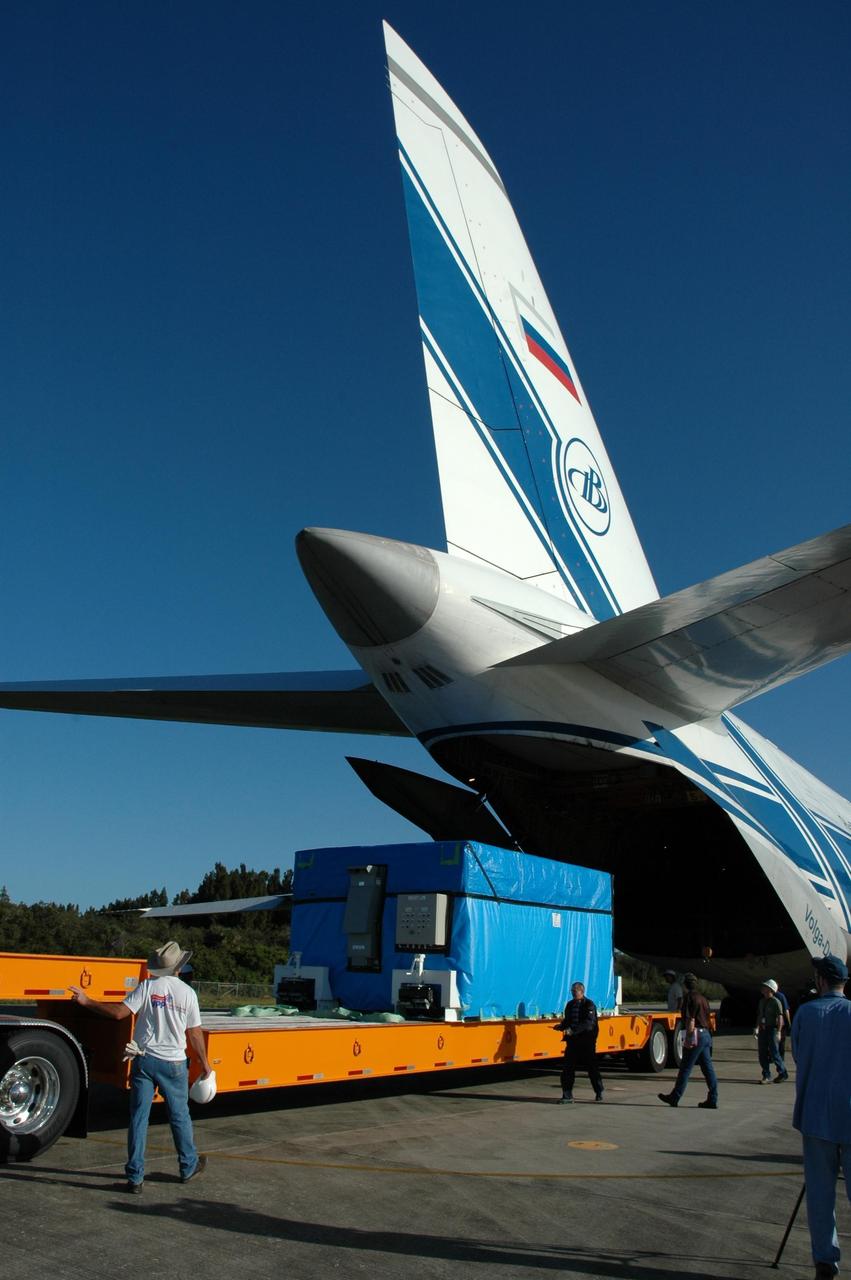
KENNEDY SPACE CENTER, FLA. -- At the KSC Shuttle Landing Facility, the remote manipulator system for the Japanese Experiment Module has been offloaded from the Antonov 124 aircraft onto a truck bed. The RMS will be transported to the Space Station Processing Facility. The JEM, named "Kibo" (Hope), is Japan's primary contribution to the International Space Station. It will enhance the unique research capabilities of the orbiting complex by providing an additional environment for astronauts to conduct science experiments. The Japanese Aerospace Exploration Agency developed the laboratory. Both the JEM and RMS are targeted for mission STS-124, to launch in early 2008. Photo credit: NASA/Dimitrios Gerondidakis

KENNEDY SPACE CENTER, FLA. -- At the KSC Shuttle Landing Facility, a truck maneuvers its bed into place for the offloading of the remote manipulator system for the Japanese Experiment Module from the Antonov 124 aircraft. The RMS will be transported to the Space Station Processing Facility. The JEM, named "Kibo" (Hope), is Japan's primary contribution to the International Space Station. It will enhance the unique research capabilities of the orbiting complex by providing an additional environment for astronauts to conduct science experiments. The Japanese Aerospace Exploration Agency developed the laboratory. Both the JEM and RMS are targeted for mission STS-124, to launch in early 2008. Photo credit: NASA/Dimitrios Gerondidakis

KENNEDY SPACE CENTER, FLA. -- At the KSC Shuttle Landing Facility, other components of the remote manipulator system for the Japanese Experiment Module are offloaded from the Antonov 124 aircraft onto a truck bed. The RMS will be transported to the Space Station Processing Facility. The JEM, named "Kibo" (Hope), is Japan's primary contribution to the International Space Station. It will enhance the unique research capabilities of the orbiting complex by providing an additional environment for astronauts to conduct science experiments. The Japanese Aerospace Exploration Agency developed the laboratory. Both the JEM and RMS are targeted for mission STS-124, to launch in early 2008. Photo credit: NASA/Dimitrios Gerondidakis

The XV-15 tilt rotor ships #1 and #2 parked on the NASA Dryden Flight Research Center ramp. The XV-15s, manufactured by Bell, were involved in limited research at Dryden in 1980 and 1981. The development of the XV-15 Tiltrotor research aircraft was initiated in 1973 with joint Army/NASA funding as a "proof of concept", or "technology demonstrator" program, with two aircraft being built by Bell Helicopter Textron (BHT) in 1977. The aircraft are powered by twin Lycoming T-53 turboshaft engines that are connected by a cross-shaft and drive three-bladed, 25 ft diameter metal rotors (the size extensively tested in a wind tunnel). The engines and main transmissions are located in wingtip nacelles to minimize the operational loads on the cross-shaft system and, with the rotors, tilt as a single unit. For takeoff, the proprotors and their engines are used in the straight-up position where the thrust is directed downward. The XV-15 then climbs vertically into the air like a helicopter. In this VTOL mode, the vehicle can lift off and hover for approximately one hour. Once off the ground, the XV-15 has the ability to fly in one of two different modes. It can fly as a helicopter, in the partially converted airplane mode. The XV-15 can also then convert from the helicopter mode to the airplane mode. This is accomplished by continuous rotation of the proprotors from the helicopter rotor position to the conventional airplane propeller position. During the ten to fifteen second conversion period, the aircraft speed increases and lift is transferred from the rotors to the wing. To land, the proprotors are rotated up to the helicopter rotor position and flown as a helicopter to a vertical landing.
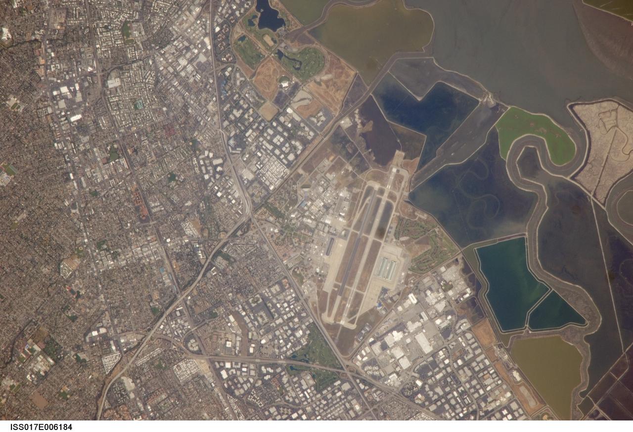
ISS017-E-006184 (3 May 2008) --- NASA Ames Research Center, Moffett Field, CA is featured in this image photographed by an Expedition 17 crewmember on the International Space Station. This view illustrates the diverse built environment surrounding NASA's Ames Research Center, or ARC located at the southernmost end of the San Francisco Bay. Founded in 1939 as an aircraft research laboratory, Ames became a NASA facility in 1958. Its original aircraft research focus was enhanced by the adjacent Moffett Field -- an active Naval Air Station until 1994 and original home of the Navy dirigible U.S.S. Macon. The large hangar for docking the U.S.S. Macon is still present at Moffett Field, and is visible in this image (center). Today, NASA ARC includes the former Naval Air Station, and continues its focus on aeronautics in addition to nanotechnology, information technology, fundamental space biology, biotechnology, thermal protection systems, and human factors research. Land use and land cover in the southern San Francisco Bay area is a diverse mix of industrial, institutional, and residential patterns. Industrial lots -- characterized by lack of green vegetation and large buildings with highly reflective white rooftops -- border NASA ARC to the west, east, and south. The city of Mountain View directly to the south appears as a dense gray-brown network of streets and residential properties with interspersed green parks. The northern boundary of NASA ARC consists of former salt ponds in the process of being returned to tidal wetlands (right). Drainage channels that predate the salt pond levees are visible at right.
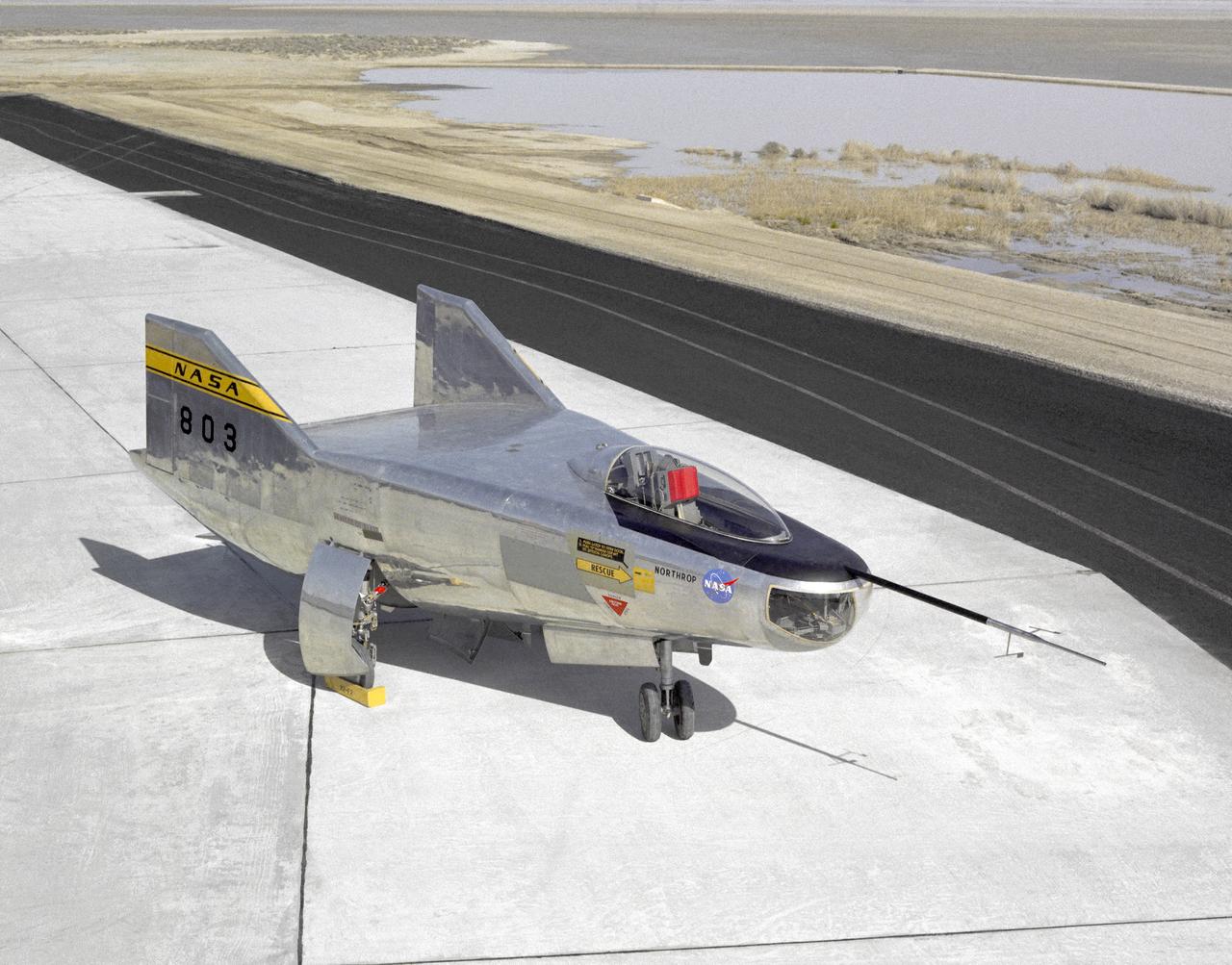
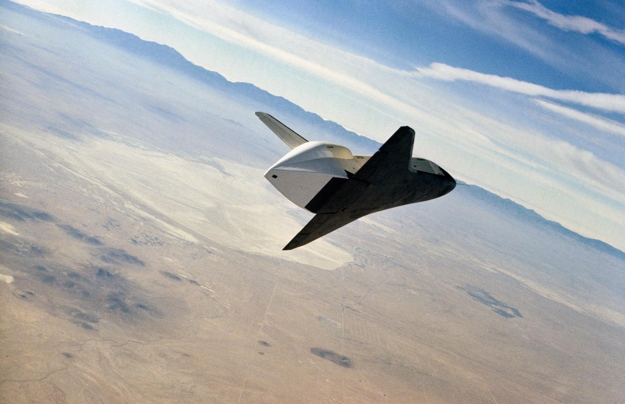
The M2-F2 Lifting Body is seen here on the ramp at the NASA Dryden Flight Research Center. The success of Dryden's M2-F1 program led to NASA's development and construction of two heavyweight lifting bodies based on studies at NASA's Ames and Langley research centers -- the M2-F2 and the HL-10, both built by the Northrop Corporation. The "M" refers to "manned" and "F" refers to "flight" version. "HL" comes from "horizontal landing" and 10 is for the tenth lifting body model to be investigated by Langley. The first flight of the M2-F2 -- which looked much like the "F1" -- was on July 12, 1966. Milt Thompson was the pilot. By then, the same B-52 used to air launch the famed X-15 rocket research aircraft was modified to also carry the lifting bodies. Thompson was dropped from the B-52's wing pylon mount at an altitude of 45,000 feet on that maiden glide flight. The M2-F2 weighed 4,620 pounds, was 22 feet long, and had a width of about 10 feet. On May 10, 1967, during the sixteenth glide flight leading up to powered flight, a landing accident severely damaged the vehicle and seriously injured the NASA pilot, Bruce Peterson. NASA pilots and researchers realized the M2-F2 had lateral control problems, even though it had a stability augmentation control system. When the M2-F2 was rebuilt at Dryden and redesignated the M2-F3, it was modified with an additional third vertical fin -- centered between the tip fins -- to improve control characteristics. The M2-F2/F3 was the first of the heavy-weight, entry-configuration lifting bodies. Its successful development as a research test vehicle answered many of the generic questions about these vehicles. NASA donated the M2-F3 vehicle to the Smithsonian Institute in December 1973. It is currently hanging in the Air and Space Museum along with the X-15 aircraft number 1, which was its hangar partner at Dryden from 1965 to 1969.
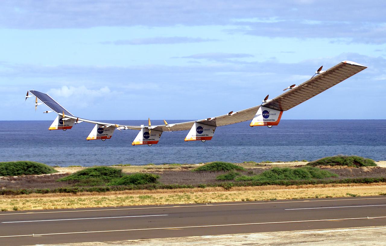
NASA's Helios Prototype aircraft taking off from the Pacific Missile Range Facility, Kauai, Hawaii, for the record flight. As a follow-on to the Centurion (and earlier Pathfinder and Pathfinder-Plus) aircraft, the solar-powered Helios Prototype is the latest and largest example of a slow-flying ultralight flying wing designed for long-duration, high-altitude Earth science or telecommunications relay missions in the stratosphere. Developed by AeroVironment, Inc., of Monrovia, California, under NASA's Environmental Research Aircraft and Sensor Technology (ERAST) project, the unique craft is intended to demonstrate two key missions: the ability to reach and sustain horizontal flight at 100,000 feet altitude on a single-day flight in 2001, and to maintain flight above 50,000 feet altitude for at least four days in 2003, with the aid of a regenerative fuel cell-based energy storage system now in development. Both of these missions will be powered by electricity derived from non-polluting solar energy. The Helios Prototype is an enlarged version of the Centurion flying wing, which flew a series of test flights at NASA's Dryden Flight Research Center in late 1998. The craft has a wingspan of 247 feet, 41 feet greater than the Centurion, 2 1/2 times that of its solar-powered Pathfinder flying wing, and longer than the wingspans of either the Boeing 747 jetliner or Lockheed C-5 transport aircraft. The remotely piloted, electrically powered Helios Prototype went aloft on its maiden low-altitude checkout flight Sept. 8, 1999, over Rogers Dry Lake adjacent to NASA's Dryden Flight Research Center in the Southern California desert. The initial flight series was flown on battery power as a risk-reduction measure. In all, six flights were flown in the Helios Protoype's initial development series. In upgrading the Centurion to the Helios Prototype configuration, AeroVironment added a sixth wing section and a fifth landing gear pod, among other improvements. The additional wingsp

In May 2014, two new studies concluded that a section of the land-based West Antarctic ice sheet had reached a point of inevitable collapse. Meanwhile, fresh observations from September 2014 showed sea ice around Antarctica had reached its greatest extent since the late 1970s. To better understand such dynamic and dramatic differences in the region's land and sea ice, researchers are travelling south to Antarctica this month for the sixth campaign of NASA’s Operation IceBridge. The airborne campaign, which also flies each year over Greenland, makes annual surveys of the ice with instrumented research aircraft. Instruments range from lasers that map the elevation of the ice surface, radars that "see" below it, and downward looking cameras to provide a natural-color perspective. The Digital Mapping System (DMS) camera acquired the above photo during the mission’s first science flight on October 16, 2009. At the time of the image, the DC-8 aircraft was flying at an altitude of 515 meters (1,700 feet) over heavily compacted first-year sea ice along the edge of the Amundsen Sea. Since that first flight, much has been gleaned from IceBridge data. For example, images from an IceBridge flight in October 2011 revealed a massive crack running about 29 kilometers (18 miles) across the floating tongue of Antarctica's Pine Island Glacier. The crack ultimately led to a 725-square-kilometer (280-square-mile) iceberg. In 2012, IceBridge data was a key part of a new map of Antarctica called Bedmap2. By combining surface elevation, ice thickness, and bedrock topography, Bedmap2 gives a clearer picture of Antarctica from the ice surface down to the land surface. Discoveries have been made in Greenland, too, including the identification of a 740-kilometer-long (460-mile-long) mega canyon below the ice sheet. Repeated measurements of land and sea ice from aircraft extend the record of observations once made by NASA’s Ice, Cloud, and Land Elevation Satellite, or ICESat, which stopped functioning in 2009. In addition to extending the ICESat record, IceBridge also sets the stage for ICESat-2, which is scheduled for launch in 2017. Credit: IceBridge DMS L0 Raw Imagery courtesy of the Digital Mapping System (DMS) team/NASA DAAC at the National Snow and Ice Data Center More info: <a href="http://earthobservatory.nasa.gov/IOTD/view.php?id=84549" rel="nofollow">earthobservatory.nasa.gov/IOTD/view.php?id=84549</a> <a href="http://earthobservatory.nasa.gov/IOTD/view.php?id=84549" rel="nofollow">earthobservatory.nasa.gov/IOTD/view.php?id=84549</a>
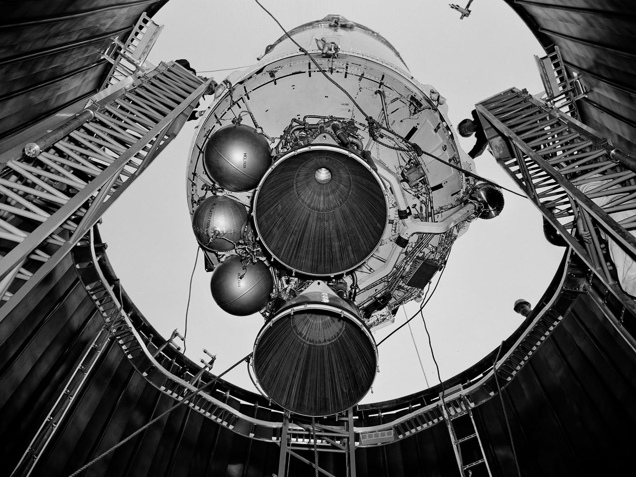
A Centaur second-stage rocket is lowered into the vacuum tank inside the Space Power Chambers at NASA’s Lewis Research Center. Centaur was to be paired with an Atlas booster to send the Surveyor spacecraft to the moon as a precursor to the Apollo landings. Lewis was assigned responsibility for the Centaur Program after the failure of its first developmental flight in May 1962. Lewis’ Altitude Wind Tunnel was converted into two large test chambers—the Space Power Chambers. The facility’s vacuum chamber, seen here, allowed the Centaur to be stood up vertically and subjected to atmospheric conditions-- pressures, temperature, and radiation--similar to those it would encounter in space. The Centaur for these tests was delivered to Cleveland in a C‒130 aircraft on September 27, 1963. The rocket was set up in the facility’s high bay where Lewis technicians and General Dynamics consultants updated its flight systems to match the upcoming Atlas-Centaur‒4 mission. Months were spent reharnessing the Centaur’s electronics, learning about the systems, and being taught how to handle flight hardware. By early spring 1964, the extensive setup of both the spacecraft and the chamber was finally completed. On March 19 the Centaur was rolled out from the shop, hoisted high into the air by a crane, and lowered into the waiting space tank. Researchers were able to verify that the Centaur’s electronics and electrical systems functioned reliably in a space environment.
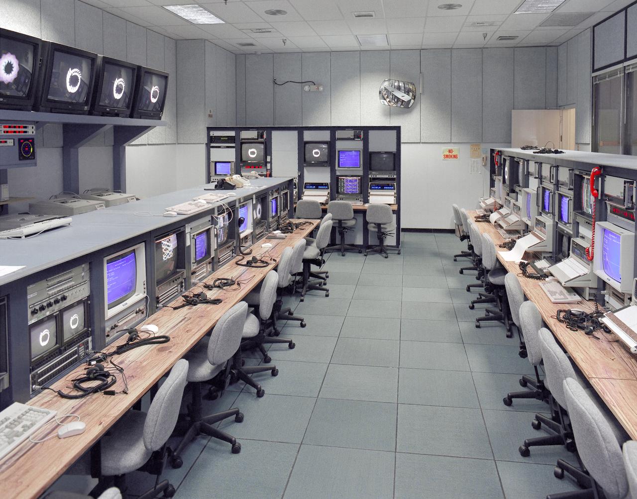
Mission control Blue Room, seen here, in building 4800 at NASA's Dryden Flight Research Center, is part of the Western Aeronautical Test Range (WATR). All aspects of a research mission are monitored from one of two of these control rooms at Dryden. The WATR consists of a highly automated complex of computer controlled tracking, telemetry, and communications systems and control room complexes that are capable of supporting any type of mission ranging from system and component testing, to sub-scale and full-scale flight tests of new aircraft and reentry systems. Designated areas are assigned for spin/dive tests, corridors are provided for low, medium, and high-altitude supersonic flight, and special STOL/VSTOL facilities are available at Ames Moffett and Crows Landing. Special use airspace, available at Edwards, covers approximately twelve thousand square miles of mostly desert area. The southern boundary lies to the south of Rogers Dry Lake, the western boundary lies midway between Mojave and Bakersfield, the northern boundary passes just south of Bishop, and the eastern boundary follows about 25 miles west of the Nevada border except in the northern areas where it crosses into Nevada.
A researcher prepares a Centaur 6A second-stage rocket for a series of tests in the Space Power Chambers’ vacuum tank at the National Aeronautics and Space Administration (NASA) Lewis Research Center. Lewis was assigned oversight of the Centaur Program in the fall of 1962. Prior to that, Centaur’s only launch had failed shortly after liftoff. Lewis engineers undertook an expansive effort to quickly resolve Centaur’s problems and prepare it for its planned missions to send Surveyor spacecraft to land on the moon. For one test program, a complete Centaur vehicle was lowered into the vacuum chamber at the Space Power Chambers to verify that its electronics and electrical systems functioned reliably in a space environment. At the time, electronic malfunctions were one of the most likely causes of failures in space. Studying these systems during long soaks inside the space tank helped the Lewis team calibrate them and facilitate the monitoring of the spacecraft during an actual flight. The Centaur for the tests was delivered to Cleveland in a C-130 aircraft on September 27, 1963. The rocket was set up in the facility’s high bay where Lewis technicians and General Dynamics consultants updated its flight systems to match the upcoming Atlas-Centaur-4 mission, as seen in this photograph.
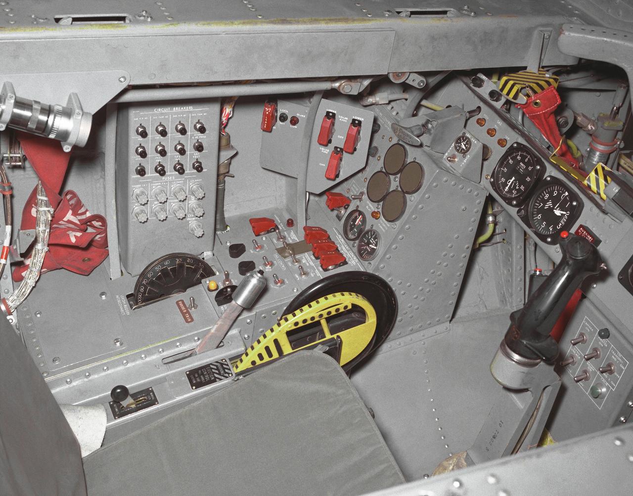
This photo shows the left side cockpit instrumentation panel of the M2-F2 Lifting Body. The success of Dryden's M2-F1 program led to NASA's development and construction of two heavyweight lifting bodies based on studies at NASA's Ames and Langley research centers -- the M2-F2 and the HL-10, both built by the Northrop Corporation. The "M" refers to "manned" and "F" refers to "flight" version. "HL" comes from "horizontal landing" and 10 is for the tenth lifting body model to be investigated by Langley. The first flight of the M2-F2 -- which looked much like the "F1" -- was on July 12, 1966. Milt Thompson was the pilot. By then, the same B-52 used to air launch the famed X-15 rocket research aircraft was modified to also carry the lifting bodies. Thompson was dropped from the B-52's wing pylon mount at an altitude of 45,000 feet on that maiden glide flight. The M2-F2 weighed 4,620 pounds, was 22 feet long, and had a width of about 10 feet. On May 10, 1967, during the sixteenth glide flight leading up to powered flight, a landing accident severely damaged the vehicle and seriously injured the NASA pilot, Bruce Peterson. NASA pilots and researchers realized the M2-F2 had lateral control problems, even though it had a stability augmentation control system. When the M2-F2 was rebuilt at Dryden and redesignated the M2-F3, it was modified with an additional third vertical fin -- centered between the tip fins -- to improve control characteristics. The M2-F2/F3 was the first of the heavy-weight, entry-configuration lifting bodies. Its successful development as a research test vehicle answered many of the generic questions about these vehicles. NASA donated the M2-F3 vehicle to the Smithsonian Institute in December 1973. It is currently hanging in the Air and Space Museum along with the X-15 aircraft number 1, which was its hangar partner at Dryden from 1965 to 1969.
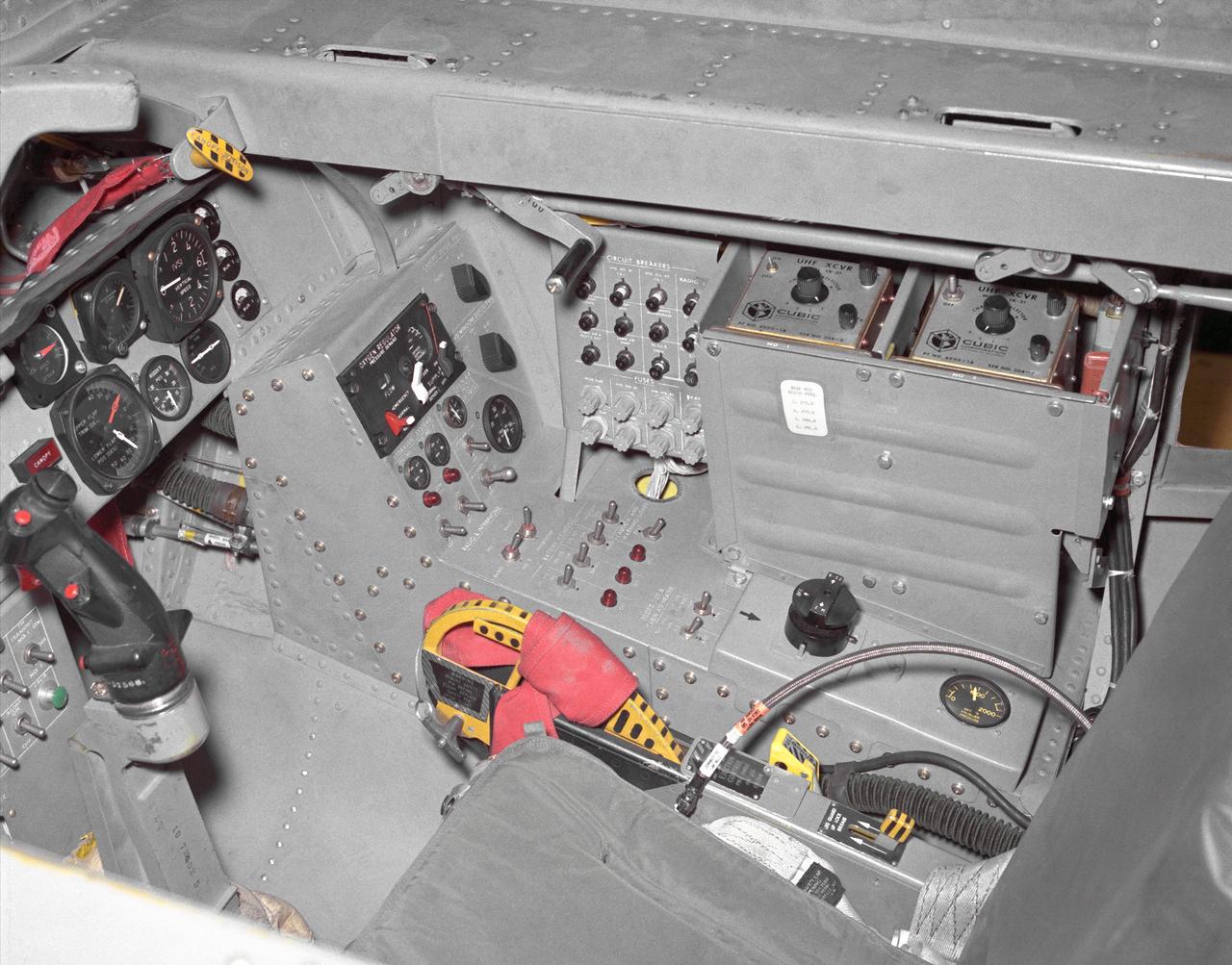
This photo shows the right side cockpit instrumentation panel of the M2-F2 Lifting Body. The success of Dryden's M2-F1 program led to NASA's development and construction of two heavyweight lifting bodies based on studies at NASA's Ames and Langley research centers -- the M2-F2 and the HL-10, both built by the Northrop Corporation. The "M" refers to "manned" and "F" refers to "flight" version. "HL" comes from "horizontal landing" and 10 is for the tenth lifting body model to be investigated by Langley. The first flight of the M2-F2 -- which looked much like the "F1" -- was on July 12, 1966. Milt Thompson was the pilot. By then, the same B-52 used to air launch the famed X-15 rocket research aircraft was modified to also carry the lifting bodies. Thompson was dropped from the B-52's wing pylon mount at an altitude of 45,000 feet on that maiden glide flight. The M2-F2 weighed 4,620 pounds, was 22 feet long, and had a width of about 10 feet. On May 10, 1967, during the sixteenth glide flight leading up to powered flight, a landing accident severely damaged the vehicle and seriously injured the NASA pilot, Bruce Peterson. NASA pilots and researchers realized the M2-F2 had lateral control problems, even though it had a stability augmentation control system. When the M2-F2 was rebuilt at Dryden and redesignated the M2-F3, it was modified with an additional third vertical fin -- centered between the tip fins -- to improve control characteristics. The M2-F2/F3 was the first of the heavy-weight, entry-configuration lifting bodies. Its successful development as a research test vehicle answered many of the generic questions about these vehicles. NASA donated the M2-F3 vehicle to the Smithsonian Institute in December 1973. It is currently hanging in the Air and Space Museum along with the X-15 aircraft number 1, which was its hangar partner at Dryden from 1965 to 1969.
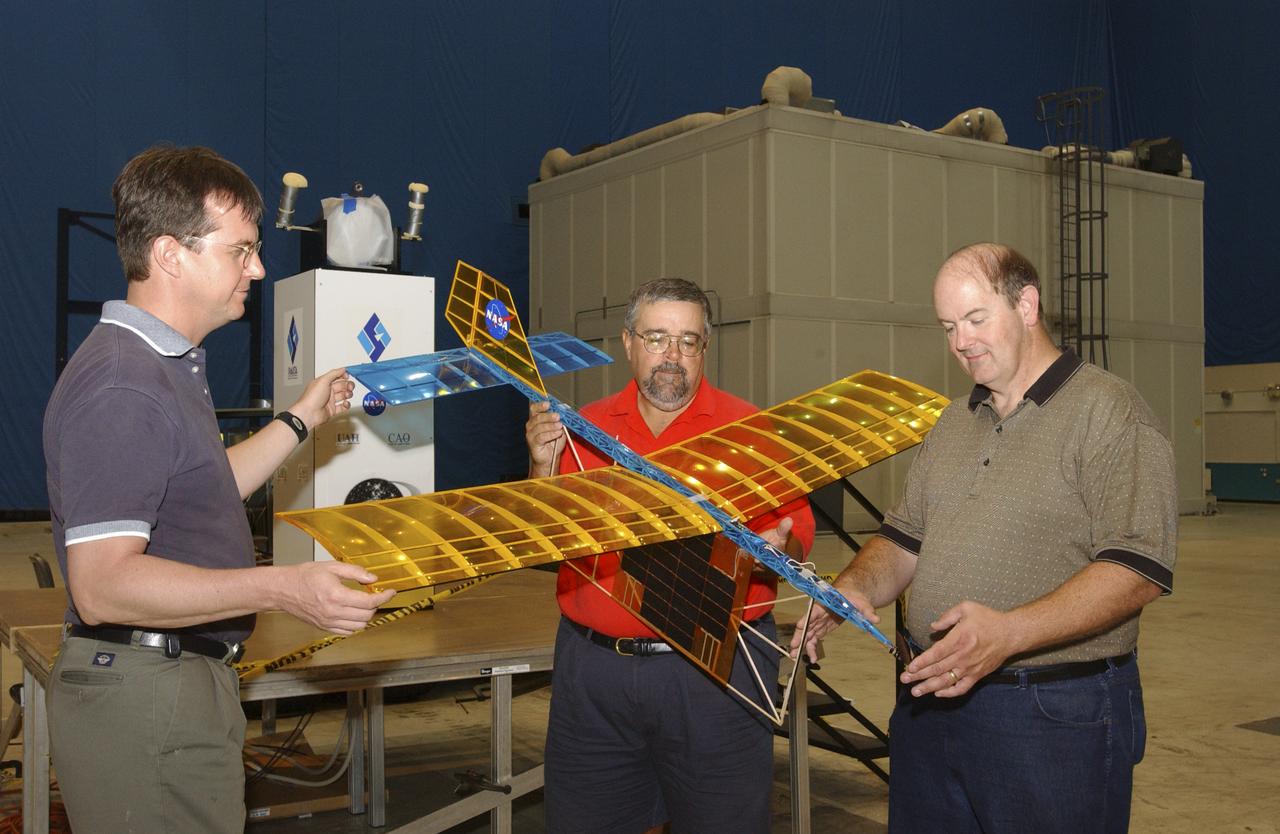
A team of NASA researchers from Marshall Space Flight Center (MSFC) and Dryden Flight Research center have proven that beamed light can be used to power an aircraft, a first-in-the-world accomplishment to the best of their knowledge. Using an experimental custom built radio-controlled model aircraft, the team has demonstrated a system that beams enough light energy from the ground to power the propeller of an aircraft and sustain it in flight. Special photovoltaic arrays on the plane, similar to solar cells, receive the light energy and convert it to electric current to drive the propeller motor. In a series of indoor flights this week at MSFC, a lightweight custom built laser beam was aimed at the airplane `s solar panels. The laser tracks the plane, maintaining power on its cells until the end of the flight when the laser is turned off and the airplane glides to a landing. The laser source demonstration represents the capability to beam more power to a plane so that it can reach higher altitudes and have a greater flight range without having to carry fuel or batteries, enabling an indefinite flight time. The demonstration was a collaborative effort between the Dryden Center at Edward's, California, where the aircraft was designed and built, and MSFC, where integration and testing of the laser and photovoltaic cells was done. Laser power beaming is a promising technology for consideration in new aircraft design and operation, and supports NASA's goals in the development of revolutionary aerospace technologies. Photographed with their invention are (from left to right): David Bushman and Tony Frackowiak, both of Dryden; and MSFC's Robert Burdine.
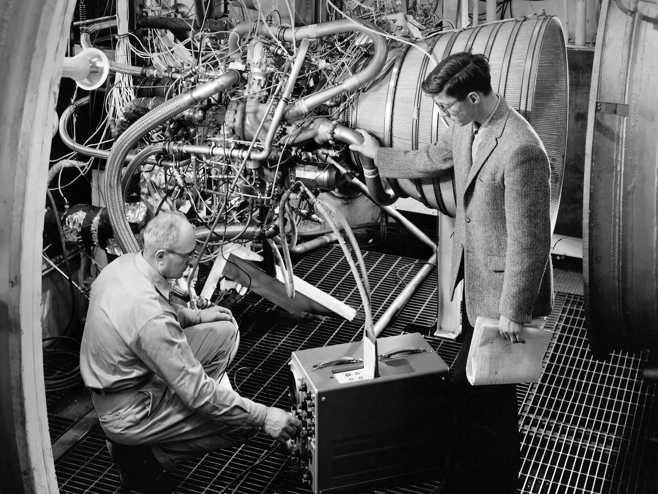
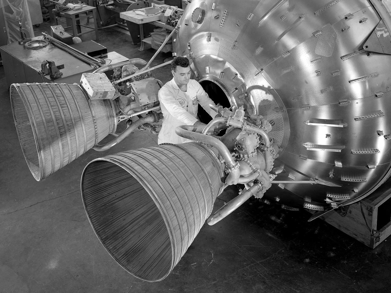
Lead Test Engineer John Kobak (right) and a technician use an oscilloscope to test the installation of a Pratt and Whitney RL-10 engine in the Propulsion Systems Laboratory at the National Aeronautics and Space Administration (NASA) Lewis Research Center. In 1955 the military asked Pratt and Whitney to develop hydrogen engines specifically for aircraft. The program was canceled in 1958, but Pratt and Whitney decided to use the experience to develop a liquid-hydrogen rocket engine, the RL-10. Two of the 15,000-pound-thrust RL-10 engines were used to power the new Centaur second-stage rocket. Centaur was designed to carry the Surveyor spacecraft on its mission to soft-land on the Moon. Pratt and Whitney ran into problems while testing the RL-10 at their facilities. NASA Headquarters assigned Lewis the responsibility for investigating the RL-10 problems because of the center’s long history of liquid-hydrogen development. Lewis’ Chemical Rocket Division began a series of tests to study the RL-10 at its Propulsion Systems Laboratory in March 1960. The facility contained two test chambers that could study powerful engines in simulated altitude conditions. The first series of RL-10 tests in early 1961 involved gimballing the engine as it fired. Lewis researchers were able to yaw and pitch the engine to simulate its behavior during a real flight.
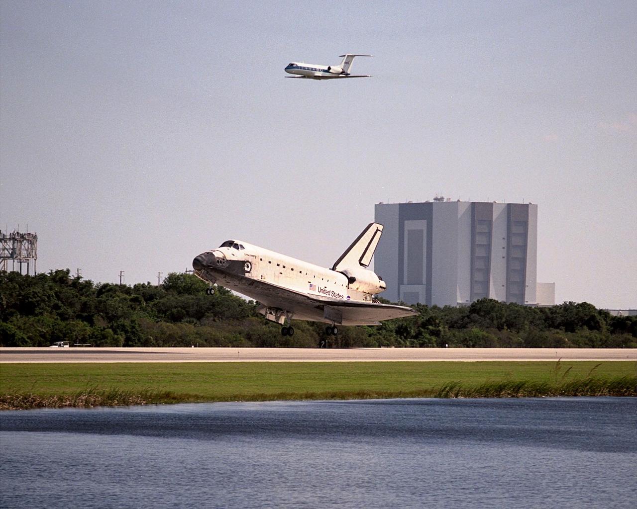
The Space Shuttle Orbiter Columbia's (STS-75) mission came to a close as the orbiter touched down on Runway 33 of Kennedy Space Center's Shuttle Landing Facility on March 9, 1996. Off to the right is the Vehicle Assembly Building and the Shuttle Training Aircraft (STA). The Mate/Demate Device (MDM) is at left. This Marshall Space Flight Center managed mission lasted 15 days and 17-hours, during which time the seven member crew conducted microgravity research with the U.S. Microgravity Payload (USMP-3), which flew for the third time. The other primary payload was the Tethered Satellite System (TSS-1R),a reflight from an earlier mission, but the satellite was lost when the tether broke just short of its fully deployed length of nearly 13 miles.
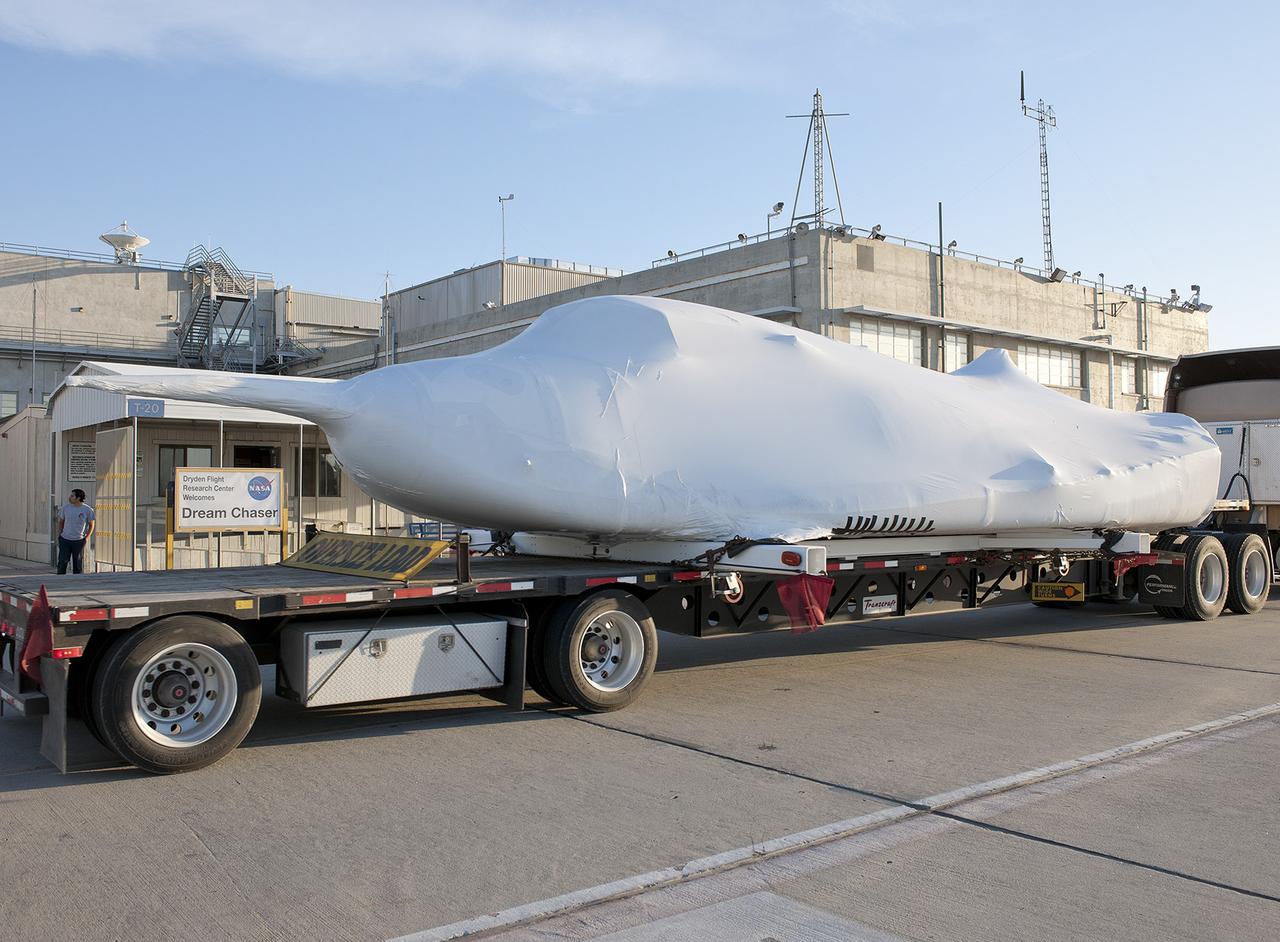
EDWARDS, Calif. – ED13-0142-10: The flatbed truck and trailer that transported Sierra Nevada Corporation, or SNC, Space Systems' Dream Chaser engineering test article pauses on the aircraft ramp at NASA's Dryden Flight Research Center on Edwards Air Force Base, Calif., upon arrival at the center. Following removal of the protective plastic wrap and reinstallation of its wings and tail structure, the Dream Chaser will begin ground tests in the next few weeks leading to approach and landing flight tests this summer. SNC is one of three companies working with NASA's Commercial Crew Program, or CCP, during the agency's Commercial Crew Integrated Capability, or CCiCap, initiative, which is intended to lead to the availability of commercial human spaceflight services for government and commercial customers. To learn more about CCP and its industry partners, visit www.nasa.gov/commercialcrew. Image credit: NASA/Tom Tschida
Members of the STS-95 crew pose in front of one of the T-38 jet aircraft that brought them to the Shuttle Landing Facility at KSC. From left, the members are Mission Specialist Scott E. Parazynski, M.D.; Pedro Duque of Spain, representing the European Space Agency (ESA); Mission Specialist Stephen K. Robinson, Ph.D.; Pilot Steven W. Lindsey; and Commander Curtis L. Brown Jr. The crew is participating in a familiarization tour of the SPACEHAB module and the equipment that will fly with them on the Space Shuttle Discovery scheduled to launch Oct. 29, 1998. The mission includes research payloads such as the Spartan solar-observing deployable spacecraft, the Hubble Space Telescope Orbital Systems Test Platform, the International Extreme Ultraviolet Hitchhiker, as well as the SPACEHAB single module with experiments on space flight and the aging process
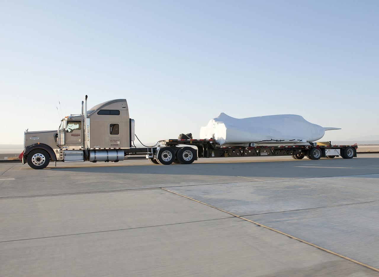
EDWARDS, Calif. – ED13-0142-11: The truck and trailer that transported the Dream Chaser engineering test article from Sierra Nevada Corporation, or SNC, Space Systems facility in Louisville, Colo., arrives on the aircraft ramp at NASA's Dryden Flight Research Center on Edwards Air Force Base, Calif., early in the morning. Based on NASA's HL-20 lifting body design, the Dream Chaser will begin its approach-and-landing flight test program in collaboration with NASA's Commercial Crew Program this summer. SNC is one of three companies working with NASA's Commercial Crew Program, or CCP, during the agency's Commercial Crew Integrated Capability, or CCiCap, initiative, which is intended to lead to the availability of commercial human spaceflight services for government and commercial customers. To learn more about CCP and its industry partners, visit www.nasa.gov/commercialcrew. Image credit: NASA/Tom Tschida
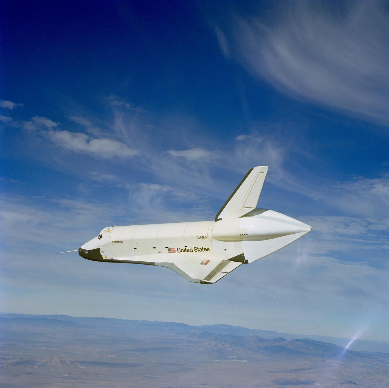
S77-28141 (13 Sept 1977) --- The shuttle Orbiter 101 "Enterprise" makes a slight turn and bank maneuver during the second free flight of the Shuttle Approach and Landing Tests (ALT) conducted on September 13, 1977, at the Dryden Flight Research Center in Southern California. The "Enterprise" separated from the NASA 747 carrier aircraft and landed following a five-minute, 28-second unpowered flight. The Orbiter 101 crew was astronauts Joe H. Engle, commander, and Richard H. Truly, pilot. The ALT free flights are designed to verify orbiter subsonic airworthiness, integrated systems operations and pilot-guided approach and landing capability and satisfy prerequisites to automatic flight control and navigation mode. The orbiter soars above the dry California desert in this post-separation view. Photographer Bill Blunck of JSC's Photographic Technology Laboratory took this picture while riding in T-38 chase plane number two. He used a 70mm Hasselblad camera with an 80mm lens.
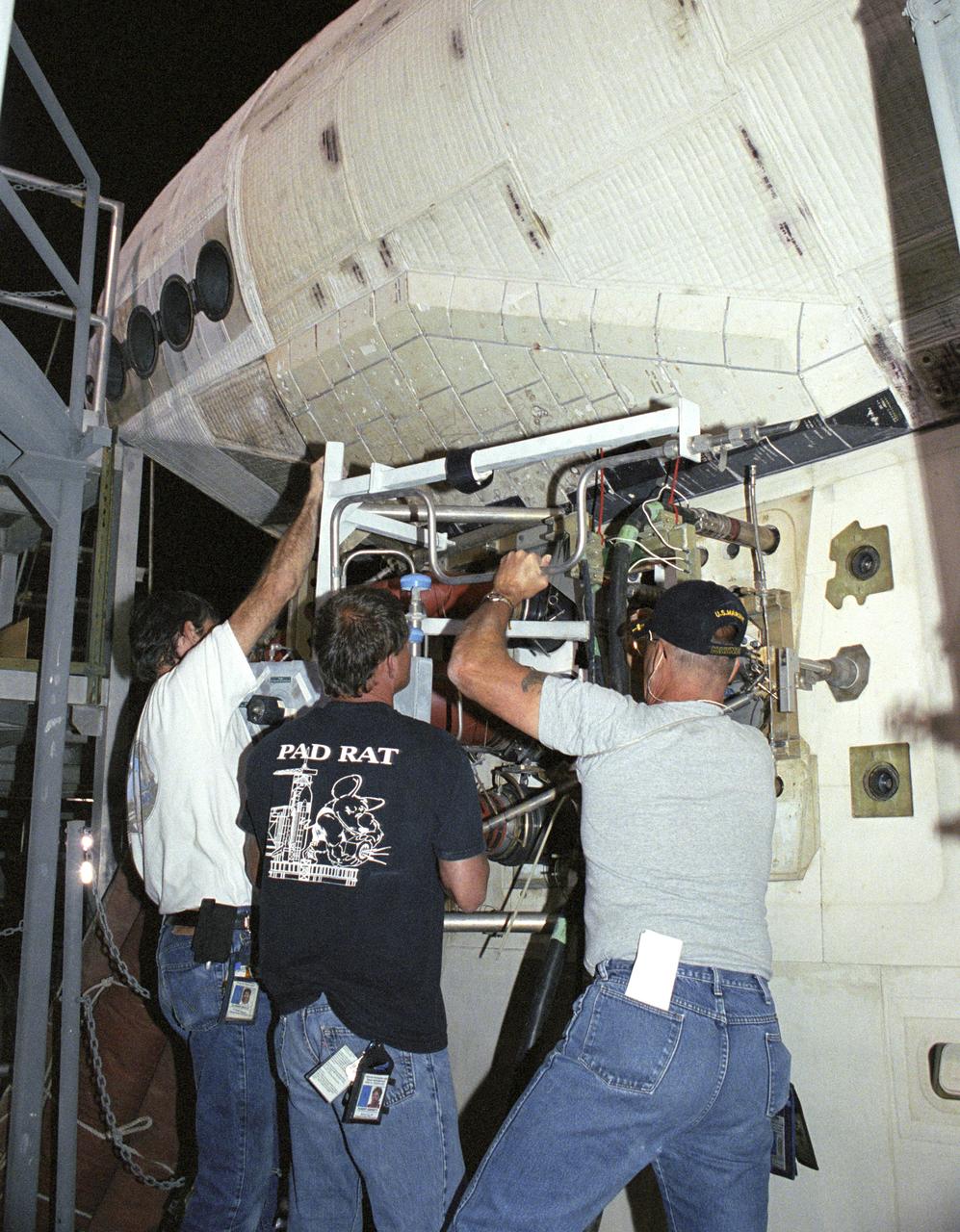
Todd Viddle; APU advanced systems technician, Robert 'Skip' Garrett; main propulsion advanced systems technician, and Dan McGrath; main propulsion systems engineer technician, remove a servicing unit from the Space Shuttle Discovery as part of it's post-flight processing at NASA's Dryden Flight Research Center. The Space Shuttles receive post-flight servicing in the Mate-Demate Device (MDD) following landings at NASA's Dryden Flight Research Center, Edwards, California. The gantry-like MDD structure is used for servicing the shuttle orbiters in preparation for their ferry flight back to the Kennedy Space Center in Florida, including mounting the shuttle atop NASA's modified Boeing 747 Shuttle Carrier Aircraft. Space Shuttle Discovery landed safely at NASA's Dryden Flight Research Center at Edwards Air Force Base in California at 5:11:22 a.m. PDT, August 9, 2005, following the very successful 14-day STS-114 return to flight mission. During their two weeks in space, Commander Eileen Collins and her six crewmates tested out new safety procedures and delivered supplies and equipment the International Space Station. Discovery spent two weeks in space, where the crew demonstrated new methods to inspect and repair the Shuttle in orbit. The crew also delivered supplies, outfitted and performed maintenance on the International Space Station. A number of these tasks were conducted during three spacewalks. In an unprecedented event, spacewalkers were called upon to remove protruding gap fillers from the heat shield on Discovery's underbelly. In other spacewalk activities, astronauts installed an external platform onto the Station's Quest Airlock and replaced one of the orbital outpost's Control Moment Gyroscopes. Inside the Station, the STS-114 crew conducted joint operations with the Expedition 11 crew. They unloaded fresh supplies from the Shuttle and the Raffaello Multi-Purpose Logistics Module. Before Discovery undocked, the crews filled Raffeallo with unneeded items
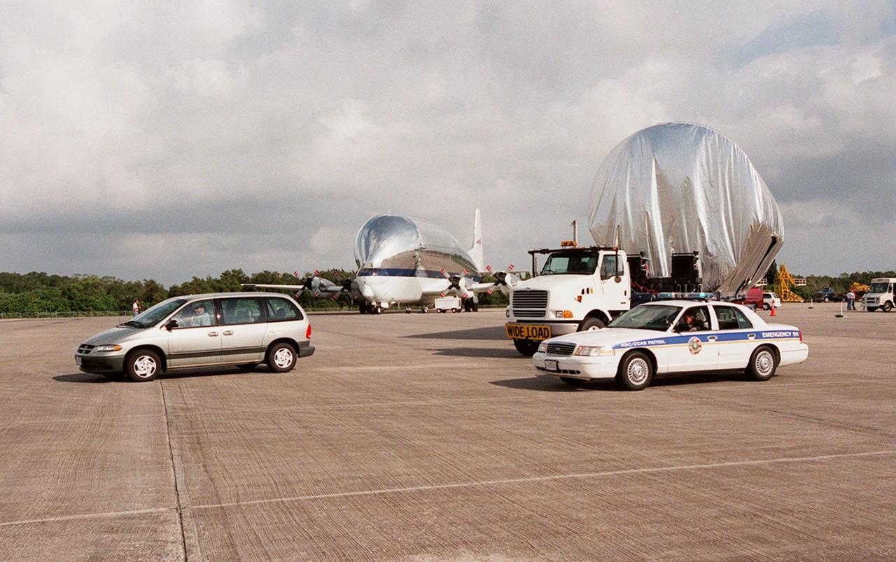
KENNEDY SPACE CENTER, FLA. -- Escort vehicles prepare to leave the Shuttle Landing Facility with the S1 truss (at right) on its trek to the Operations and Checkout Building. Manufactured by the Boeing Co. in Huntington Beach, Calif., this component of the ISS is the first starboard (right-side) truss segment, whose main job is providing structural support for the orbiting research facility's radiator panels that cool the Space Station's complex power system. The S1 truss segment also will house communications systems, external experiment positions and other subsystems. Primarily constructed of aluminum, the truss segment is 45 feet long, 15 feet wide and 6 feet tall. When fully outfitted, it will weigh 31,137 pounds. The truss is slated for flight in 2001. The truss arrived at KSC aboard NASA's Super Guppy, seen in the background. The aircraft is uniquely built with a 25-foot diameter fuselage designed to handle oversized loads and a "fold-away" nose that opens 110 degrees for cargo loading. A system of rails in the cargo compartment, used with either Guppy pallets or fixtures designed for specific cargo, makes cargo loading simple and efficient. Rollers mounted in the rails allow pallets or fixtures to be moved by an electric winch mounted beneath the cargo floor. Automatic hydraulic lock pins in each rail secure the pallet for flight
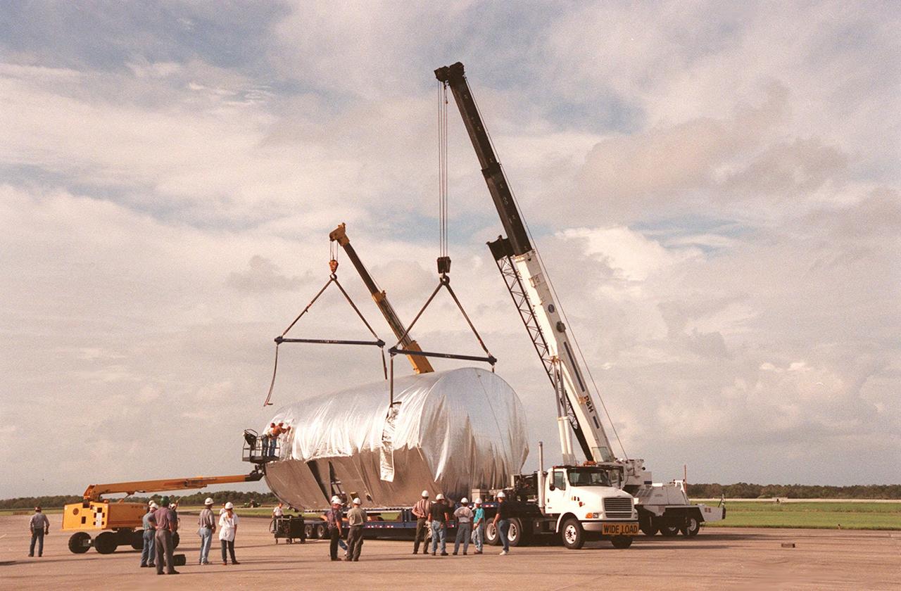
KENNEDY SPACE CENTER, FLA. -- At the Shuttle Landing Facility, workers attach cranes to the S1 truss, a segment of the International Space Station, to lift the truss to a payload transporter for its transfer to the Operations and Checkout Building. Manufactured by the Boeing Co. in Huntington Beach, Calif., this component of the ISS is the first starboard (right-side) truss segment, whose main job is providing structural support for the orbiting research facility's radiator panels that cool the Space Station's complex power system. The S1 truss segment also will house communications systems, external experiment positions and other subsystems. Primarily constructed of aluminum, the truss segment is 45 feet long, 15 feet wide and 6 feet tall. When fully outfitted, it will weigh 31,137 pounds. The truss is slated for flight in 2001. The truss arrived at KSC aboard NASA's Super Guppy, with a 25-foot diameter fuselage designed to handle oversized loads. Loading the Guppy is easy because of the unique "fold-away" nose of the aircraft that opens 110 degrees for cargo loading. A system of rails in the cargo compartment, used with either Guppy pallets or fixtures designed for specific cargo, makes cargo loading simple and efficient. Rollers mounted in the rails allow pallets or fixtures to be moved by an electric winch mounted beneath the cargo floor. Automatic hydraulic lock pins in each rail secure the pallet for flight
Robert 'Skip' Garrett; main propulsion advanced systems technician, and Chris Jacobs; main propulsion systems engineering technician, inspect external tank attachment fittings on the Space Shuttle Discovery as part of it's post-flight processing at NASA's Dryden Flight Research Center. The Space Shuttles receive post-flight servicing in the Mate-Demate Device (MDD) following landings at NASA's Dryden Flight Research Center, Edwards, California. The gantry-like MDD structure is used for servicing the shuttle orbiters in preparation for their ferry flight back to the Kennedy Space Center in Florida, including mounting the shuttle atop NASA's modified Boeing 747 Shuttle Carrier Aircraft. Space Shuttle Discovery landed safely at NASA's Dryden Flight Research Center at Edwards Air Force Base in California at 5:11:22 a.m. PDT, August 9, 2005, following the very successful 14-day STS-114 return to flight mission. During their two weeks in space, Commander Eileen Collins and her six crewmates tested out new safety procedures and delivered supplies and equipment the International Space Station. Discovery spent two weeks in space, where the crew demonstrated new methods to inspect and repair the Shuttle in orbit. The crew also delivered supplies, outfitted and performed maintenance on the International Space Station. A number of these tasks were conducted during three spacewalks. In an unprecedented event, spacewalkers were called upon to remove protruding gap fillers from the heat shield on Discovery's underbelly. In other spacewalk activities, astronauts installed an external platform onto the Station's Quest Airlock and replaced one of the orbital outpost's Control Moment Gyroscopes. Inside the Station, the STS-114 crew conducted joint operations with the Expedition 11 crew. They unloaded fresh supplies from the Shuttle and the Raffaello Multi-Purpose Logistics Module. Before Discovery undocked, the crews filled Raffeallo with unneeded items and returned to Shuttle pa
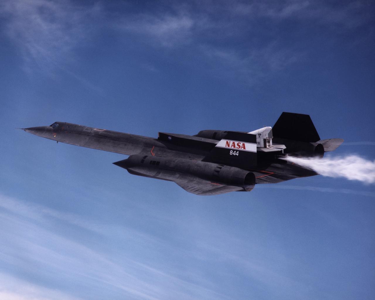
The NASA SR-71A successfully completed its first cold flow flight as part of the NASA/Rocketdyne/Lockheed Martin Linear Aerospike SR-71 Experiment (LASRE) at NASA's Dryden Flight Research Center, Edwards, California on March 4, 1998. During a cold flow flight, gaseous helium and liquid nitrogen are cycled through the linear aerospike engine to check the engine's plumbing system for leaks and to check the engine operating characterisitics. Cold-flow tests must be accomplished successfully before firing the rocket engine experiment in flight. The SR-71 took off at 10:16 a.m. PST. The aircraft flew for one hour and fifty-seven minutes, reaching a maximum speed of Mach 1.58 before landing at Edwards at 12:13 p.m. PST. "I think all in all we had a good mission today," Dryden LASRE Project Manager Dave Lux said. Flight crew member Bob Meyer agreed, saying the crew "thought it was a really good flight." Dryden Research Pilot Ed Schneider piloted the SR-71 during the mission. Lockheed Martin LASRE Project Manager Carl Meade added, "We are extremely pleased with today's results. This will help pave the way for the first in-flight engine data-collection flight of the LASRE."
Flight Crew Systems Technicians Ray Smith and Raphael Rodriguez remove one of the Extravehicular Mobility Units, or EMUs, from the Space Shuttle Discovery after it's successful landing at NASA's Dryden Flight Research Center. The Space Shuttles receive post-flight servicing in the Mate-Demate Device (MDD) following landings at NASA's Dryden Flight Research Center, Edwards, California. The gantry-like MDD structure is used for servicing the shuttle orbiters in preparation for their ferry flight back to the Kennedy Space Center in Florida, including mounting the shuttle atop NASA's modified Boeing 747 Shuttle Carrier Aircraft. Space Shuttle Discovery landed safely at NASA's Dryden Flight Research Center at Edwards Air Force Base in California at 5:11:22 a.m. PDT, August 9, 2005, following the very successful 14-day STS-114 return to flight mission. During their two weeks in space, Commander Eileen Collins and her six crewmates tested out new safety procedures and delivered supplies and equipment the International Space Station. Discovery spent two weeks in space, where the crew demonstrated new methods to inspect and repair the Shuttle in orbit. The crew also delivered supplies, outfitted and performed maintenance on the International Space Station. A number of these tasks were conducted during three spacewalks. In an unprecedented event, spacewalkers were called upon to remove protruding gap fillers from the heat shield on Discovery's underbelly. In other spacewalk activities, astronauts installed an external platform onto the Station's Quest Airlock and replaced one of the orbital outpost's Control Moment Gyroscopes. Inside the Station, the STS-114 crew conducted joint operations with the Expedition 11 crew. They unloaded fresh supplies from the Shuttle and the Raffaello Multi-Purpose Logistics Module. Before Discovery undocked, the crews filled Raffeallo with unneeded items and returned to Shuttle payload bay. Discovery launched on July 26 and spent almost 14
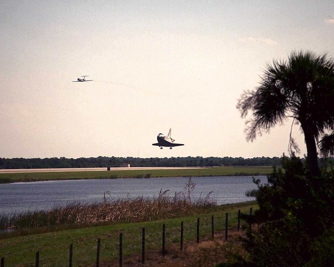
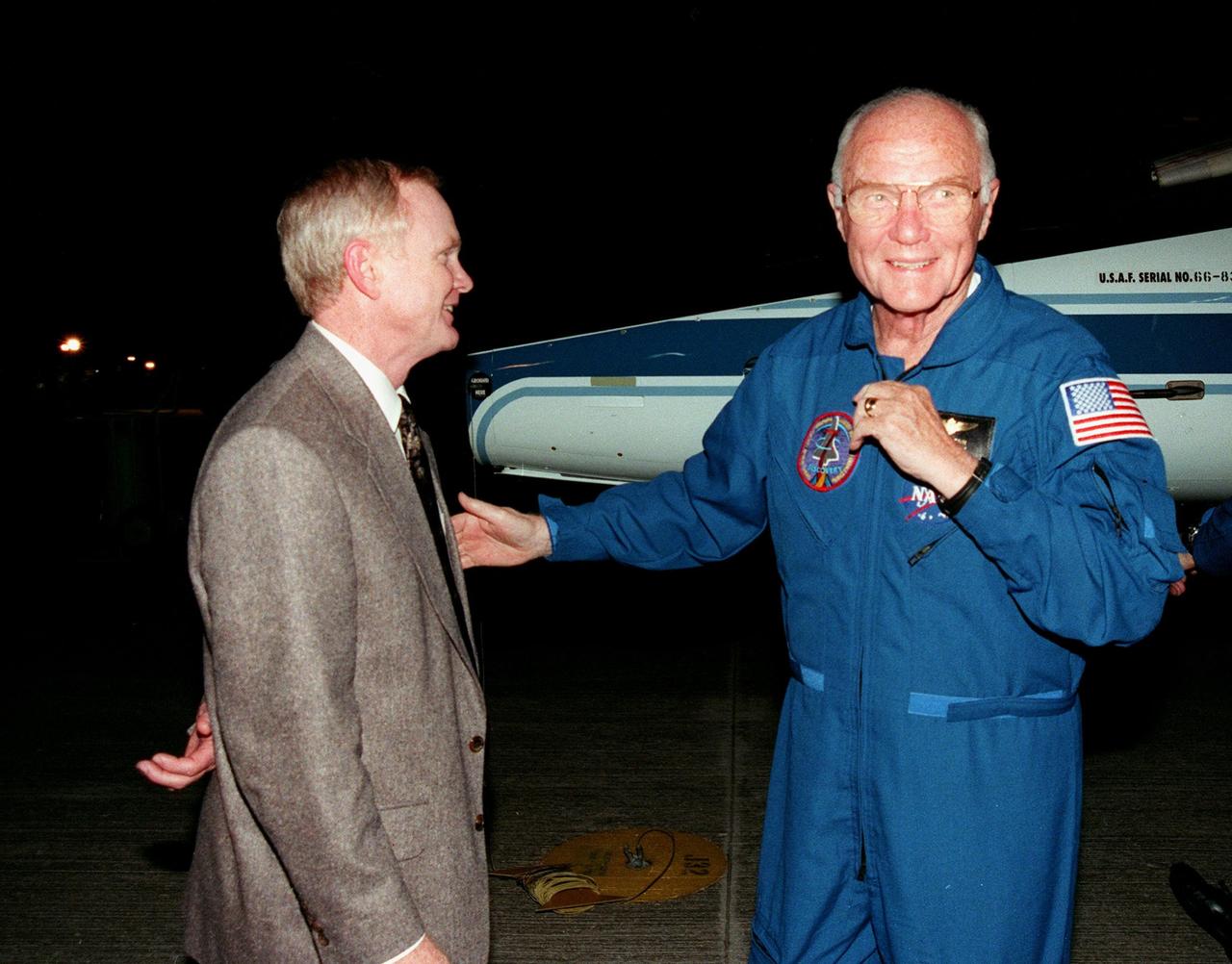
KENNEDY SPACE CENTER, FLA. -- Seen from across the creek bordering runway 33 at the Shuttle Landing Facility, orbiter Discovery touches down after a successful mission of nine days and 3.6 million miles. Flying above it (left) is the Shuttle Training Aircraft. Main gear touchdown was at 12:04 p.m. EST, landing on orbit 135. The STS-95 crew consists of Mission Commander Curtis L. Brown Jr.; Pilot Steven W. Lindsey; Mission Specialist Scott E. Parazynski; Mission Specialist Stephen K. Robinson; Payload Specialist John H. Glenn Jr., senator from Ohio; Mission Specialist Pedro Duque, with the European Space Agency (ESA); and Payload Specialist Chiaki Mukai, with the National Space Development Agency of Japan (NASDA). The mission included research payloads such as the Spartan solar-observing deployable spacecraft, the Hubble Space Telescope Orbital Systems Test Platform, the International Extreme Ultraviolet Hitchhiker, as well as the SPACEHAB single module with experiments on space flight and the aging process
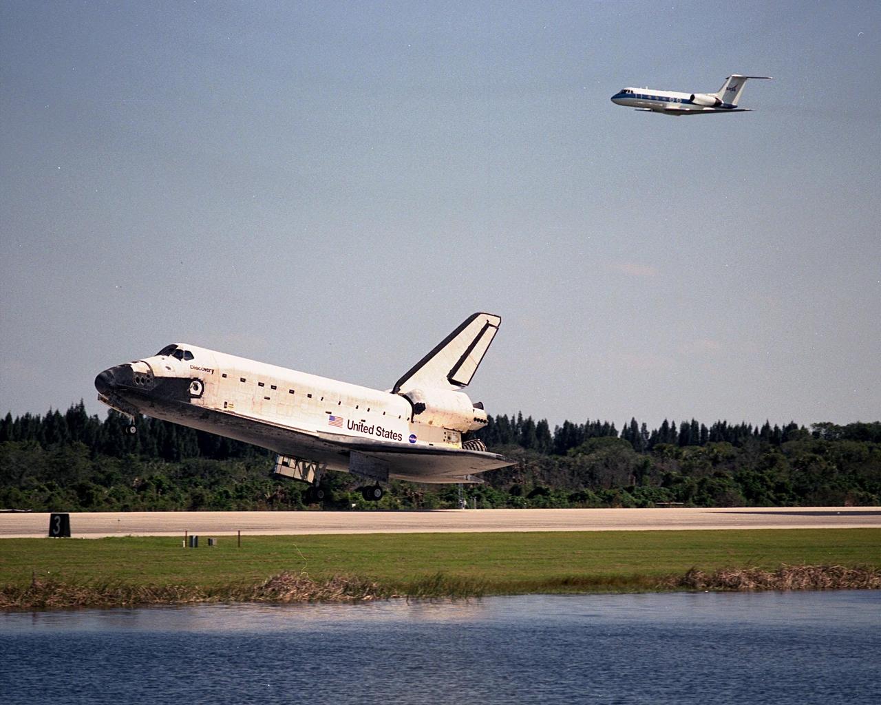
The Shuttle Training Aircraft (top) seems to chase orbiter Discovery as it touches down at the Shuttle Landing Facility after a successful mission of nearly nine days and 3.6 million miles. Main gear touchdown was at 12:04 p.m. EST, landing on orbit 135. In the background, right, is the Vehicle Assembly Building. The STS-95 crew consists of Mission Commander Curtis L. Brown Jr.; Pilot Steven W. Lindsey; Mission Specialist Scott E. Parazynski; Mission Specialist Stephen K. Robinson; Payload Specialist John H. Glenn Jr., senator from Ohio; Mission Specialist Pedro Duque, with the European Space Agency (ESA); and Payload Specialist Chiaki Mukai, with the National Space Development Agency of Japan (NASDA). The mission included research payloads such as the Spartan solar-observing deployable spacecraft, the Hubble Space Telescope Orbital Systems Test Platform, the International Extreme Ultraviolet Hitchhiker, as well as the SPACEHAB single module with experiments on space flight and the aging process
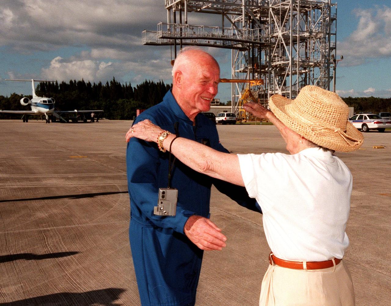
STS-95 Payload Specialist John H. Glenn Jr., senator from Ohio, reaches to embrace his wife, Annie, after landing at Kennedy Space Center's Shuttle Landing Facility aboard a T-38 jet. Behind the couple is the mate/demate device used to raise and lower the orbiter from its shuttle carrier aircraft during ferry operations. Glenn and other crewmembers flew into KSC to make final preparations for launch. Targeted for liftoff at 2 p.m. on Oct. 29, the STS-95 mission includes research payloads such as the Spartan solar-observing deployable spacecraft, the Hubble Space Telescope Orbital Systems Test Platform, the International Extreme Ultraviolet Hitchhiker, as well as the SPACEHAB single module with experiments on space flight and the aging process. The mission is expected to last 8 days, 21 hours and 49 minutes, and return to KSC on Nov. 7. The other STS-95 crew members are Mission Commander Curtis L. Brown Jr., Pilot Steven W. Lindsey, Mission Specialist Scott E. Parazynski, Mission Specialist Stephen K. Robinson, Mission Specialist Pedro Duque, with the European Space Agency (ESA), and Payload Specialist Chiaki Mukai, with the National Space Development Agency of Japan (NASDA)
Viewed across the creek bordering runway 33, orbiter Discovery prepares to touch down at the Shuttle Landing Facility after a successful mission of nearly nine days and 3.6 million miles. Flying above it is the Shuttle Training Aircraft. Main gear touchdown was at 12:04 p.m. EST, landing on orbit 135. In the background, right, is the Vehicle Assembly Building. The STS-95 crew consists of Mission Commander Curtis L. Brown Jr.; Pilot Steven W. Lindsey; Mission Specialist Scott E. Parazynski; Mission Specialist Stephen K. Robinson; Payload Specialist John H. Glenn Jr., senator from Ohio; Mission Specialist Pedro Duque, with the European Space Agency (ESA); and Payload Specialist Chiaki Mukai, with the National Space Development Agency of Japan (NASDA). The mission included research payloads such as the Spartan solar-observing deployable spacecraft, the Hubble Space Telescope Orbital Systems Test Platform, the International Extreme Ultraviolet Hitchhiker, as well as the SPACEHAB single module with experiments on space flight and the aging process
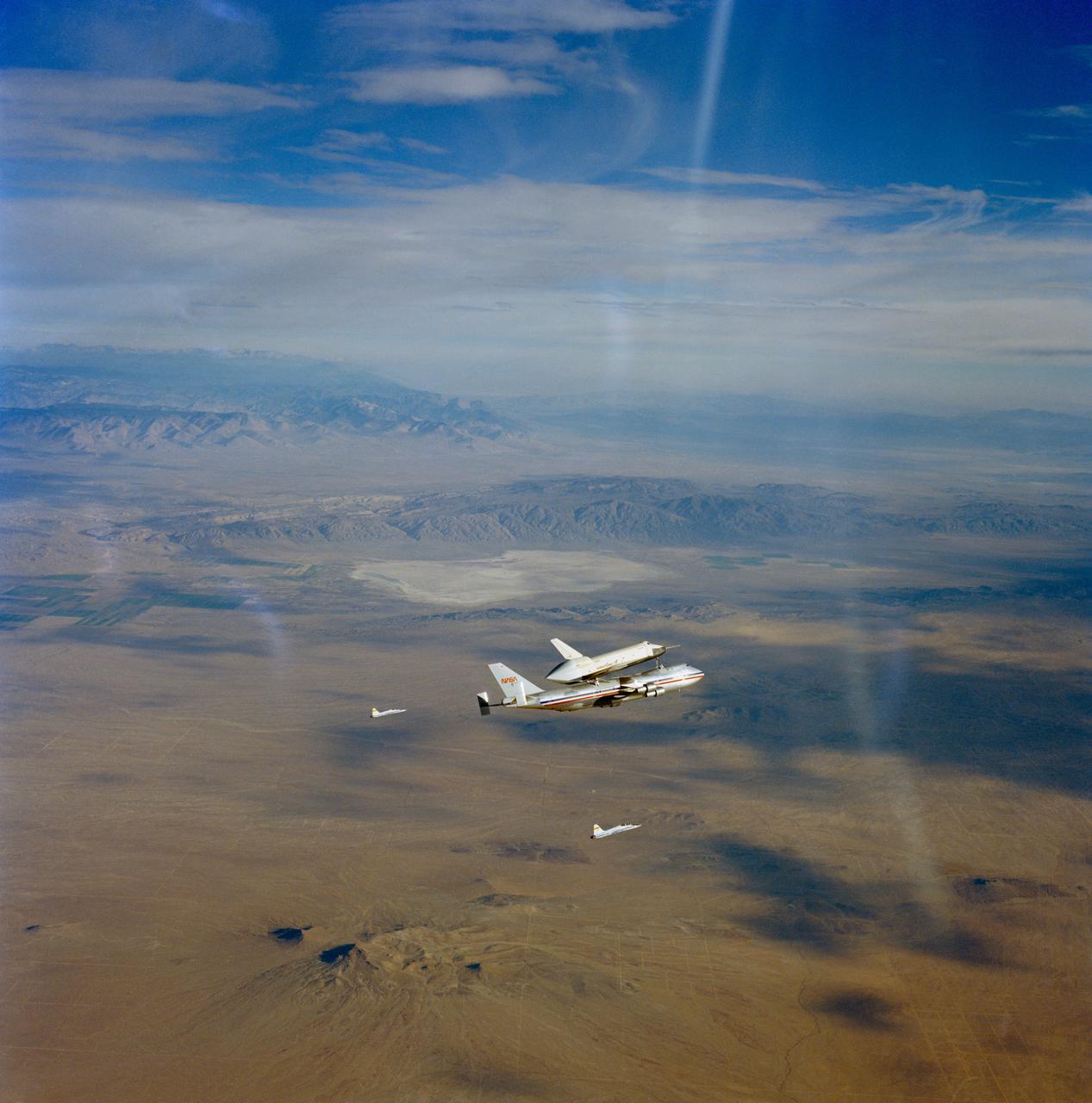
S77-28139 (13 Sept 1977) --- The Orbiter 101 "Enterprise" is seen riding "piggy-back" atope the NASA 747 carrier aircraft during the second free flight of the Shuttle Approach and Landing Tests (ALT) conducted on September 13, 1977, at the Dryden Flight Research Center in Southern California. Moments later the Orbiter 101 separated from the 747 and made a five-minute, 28-second unpowered flight before landing. Astronauts Joe H. Engle, commander, and Richard H. Truly, pilot, were the crew of the "Enterprise." two T-38 chase planes are seen in the background. The ALT free flights are designed to verify orbiter subsonic airworthiness, integrated systems operations and pilot-guided approach andlanding capability and satisfy prerequisites to automatic flight control and navigation mode. Astronaut Vance D. Brand took this picture while riding in T-38 chase plane number five. He used a 70mm Hasselblad camera with an 80mm lens.
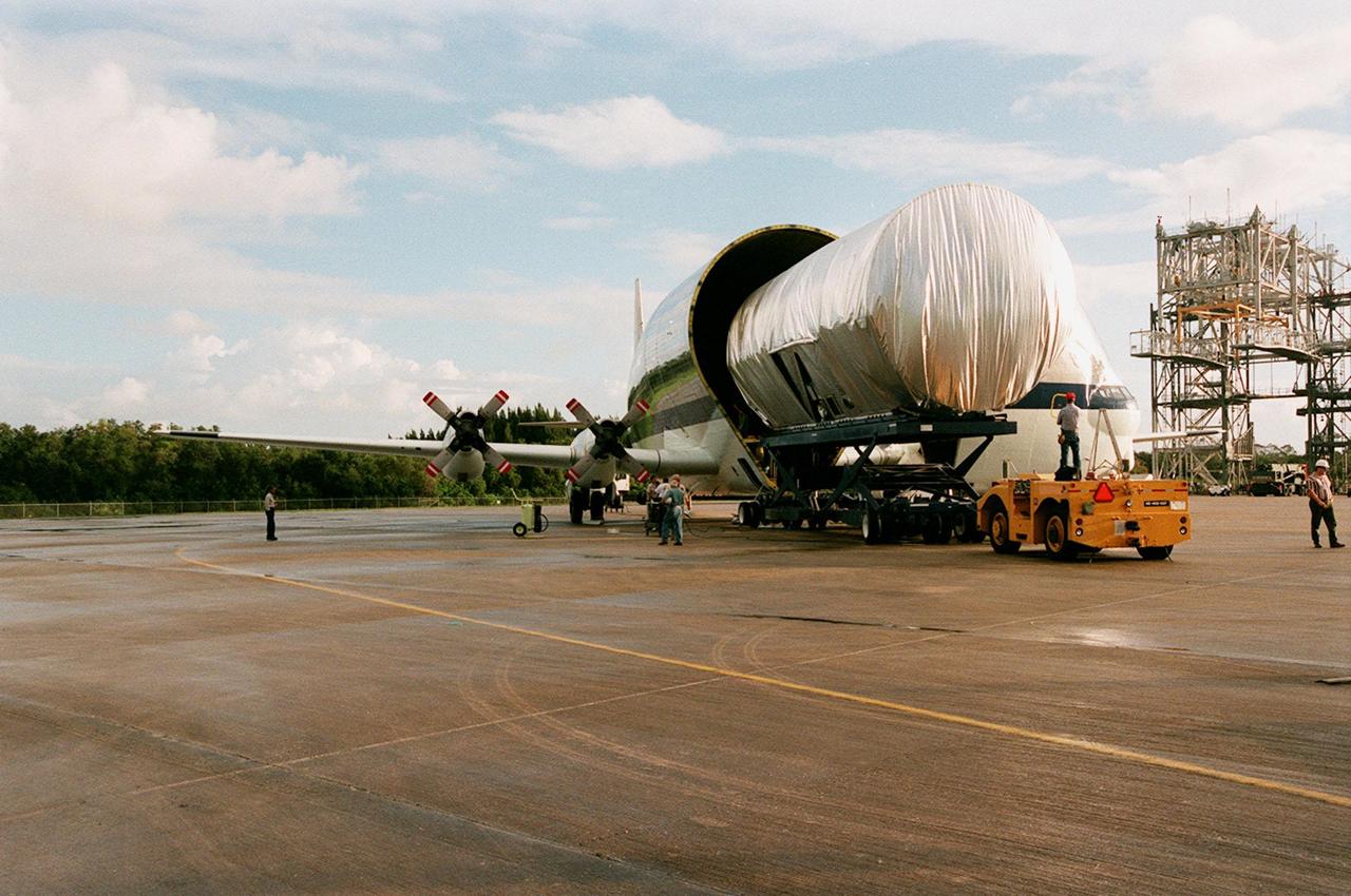
KENNEDY SPACE CENTER, FLA. -- At the Shuttle Landing Facility, the newly arrived S1 truss, a segment of the International Space Station (ISS), is offloaded from NASA's Super Guppy aircraft. Manufactured by the Boeing Co. in Huntington Beach, Calif., this component of the ISS is the first starboard (right-side) truss segment, whose main job is providing structural support for the orbiting research facility's radiator panels that cool the Space Station's complex power system. The S1 truss segment also will house communications systems, external experiment positions and other subsystems. Primarily constructed of aluminum, the truss segment is 45 feet long, 15 feet wide and 6 feet tall. When fully outfitted, it will weigh 31,137 pounds. The truss is slated for flight in 2001. The Super Guppy, with its 25-foot diameter fuselage designed to handle oversized loads, is well prepared to transport the truss and other ISS segments. Loading the Guppy is easy because of the unique "fold-away" nose of the aircraft that opens 110 degrees for cargo loading. A system of rails in the cargo compartment, used with either Guppy pallets or fixtures designed for specific cargo, makes cargo loading simple and efficient. Rollers mounted in the rails allow pallets or fixtures to be moved by an electric winch mounted beneath the cargo floor. Automatic hydraulic lock pins in each rail secure the pallet for flight. The truss is being transferred to the Operations and Checkout Building
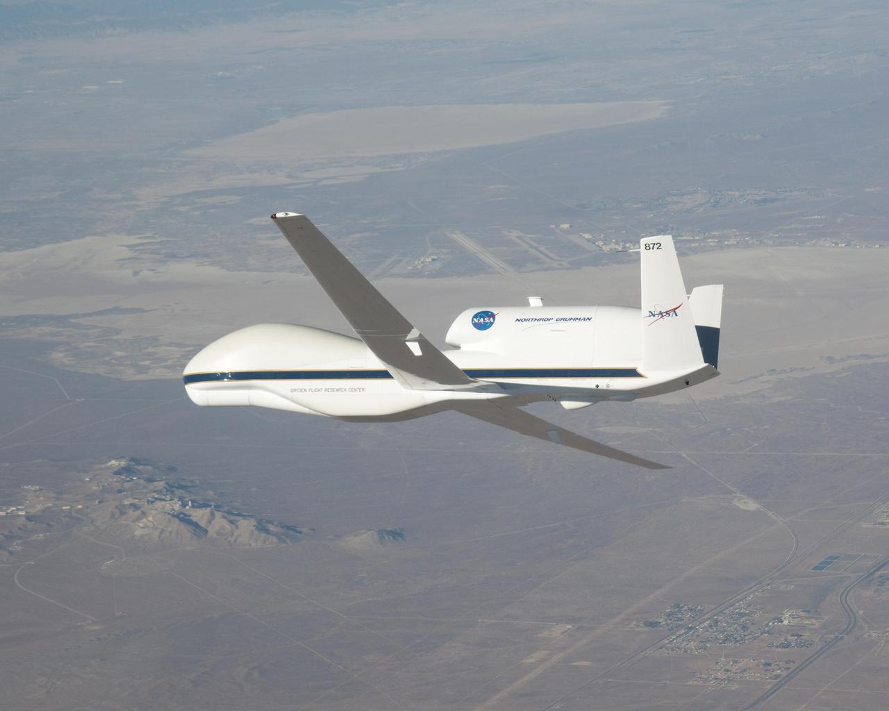
NASA image acquired October 23, 2009. At NASA’s Dryden Research Center in California, a group of engineers, scientists, and aviation technicians have set up camp in a noisy, chilly hangar on Edwards Air Force base. For the past two weeks, they have been working to mount equipment—from HD video cameras to ozone sensors—onto NASA’s Global Hawk, a remote-controlled airplane that can fly for up to 30 hours at altitudes up to 65,000 feet. The team is gearing up for the Global Hawk Pacific campaign, a series of four or five scientific research flights that will take the Global Hawk over the Pacific Ocean and Arctic regions. The 44-foot-long aircraft, with its comically large nose and 116-foot wingspan is pictured in the photograph above, banking for landing over Rogers Dry Lake in California at the end of a test flight on October 23, 2009. The long wings carry the plane’s fuel, and the bulbous nose is one of the payload bays, which house the science instruments. For the Global Hawk Pacific campaign, the robotic aircraft will carry ten science instruments that will sample the chemical composition of air in the troposphere (the atmospheric layer closest to Earth) and the stratosphere (the layer above the troposphere). The mission will also observe clouds and aerosol particles in the troposphere. The primary purpose of the mission is to collect observations that can be used to check the accuracy of simultaneous observations collected by NASA’s Aura satellite. Co-lead scientist Paul Newman from Goddard Space Flight Center is writing about the ground-breaking mission for the Earth Observatory’s Notes from the Field blog. NASA Photograph by Carla Thomas. <b><a href="http://www.nasa.gov/centers/goddard/home/index.html" rel="nofollow">NASA Goddard Space Flight Center</a></b> is home to the nation's largest organization of combined scientists, engineers and technologists that build spacecraft, instruments and new technology to study the Earth, the sun, our solar system, and the universe. To learn more about this image go to: <a href="http://earthobservatory.nasa.gov/IOTD/view.php?id=43291" rel="nofollow">earthobservatory.nasa.gov/IOTD/view.php?id=43291</a>
Pilot Joe Algranti climbs into the cockpit of a McDonnell F2H-2B Banshee on the tarmac at the National Advisory Committee for Aeronautics (NACA) Lewis Flight Propulsion Laboratory. Nine months later the laboratory became part of the new National Aeronautics and Space Administration, and the NACA logo was permanently removed from the hangar. Algranti served as a Navy fighter pilot from 1946 to 1947 and earned a Physics degree from the University of North Carolina. He joined the NACA Lewis staff in 1951 witnessed the technological transformation from high speed flight to space. At Lewis Algranti piloted icing research flights, operated the liquid-hydrogen pump system for Project Bee, and served as the primary test subject for the Multi-Axis Space Test Inertia Facility (MASTIF). The MASTIF was a device used to train the Mercury astronauts how to control a spinning capsule. In 1960, Algranti and fellow Lewis pilots Warren North and Harold Ream transferred to NASA’s Space Task Group at Langley to actively participate in the space program. Two years later, Algranti became the Chief of Aircraft Operations and Chief Test Pilot at NASA’s new Manned Space Center in Houston. Algranti earned notoriety in 1968 when he test flew the first Lunar Landing Training Vehicle. He operated the vehicle four minutes before being forced to eject moments before it impacted the ground. Algranti also flew the NASA’s modified Boeing 747 Shuttle Carrier Aircraft, the Super Guppy, and the KC-135 "Vomit Comet" training aircraft. He retired in 1992 with over 40 years of NASA service.
STS-95 Payload Specialist John H. Glenn Jr. arrives aboard a T-38 jet aircraft at the Shuttle Landing Facility at KSC to participate in a Terminal Countdown Demonstration Test (TCDT) for the launch scheduled for liftoff on Oct. 29, 1998. The TCDT includes activities to familiarize them with the mission, training in emergency exit from the orbiter and launch pad, and a simulated main engine cut-off exercise. Other crew members on the mission are Mission Commander Curtis L. Brown , Pilot Steven W. Lindsey; Mission Specialists Scott E. Parazynski, Stephen K. Robinson, and Pedro Duque of Spain, representing the European Space Agency (ESA); and Payload Specialist Chiaki Mukai, representing the National Space Development Agency of Japan (NASDA). The STS-95 mission includes research payloads such as the Spartan solar-observing deployable spacecraft, the Hubble Space Telescope Orbital Systems Test Platform, the International Extreme Ultraviolet Hitchhiker, as well as the SPACEHAB single module with experiments on space flight and the aging process
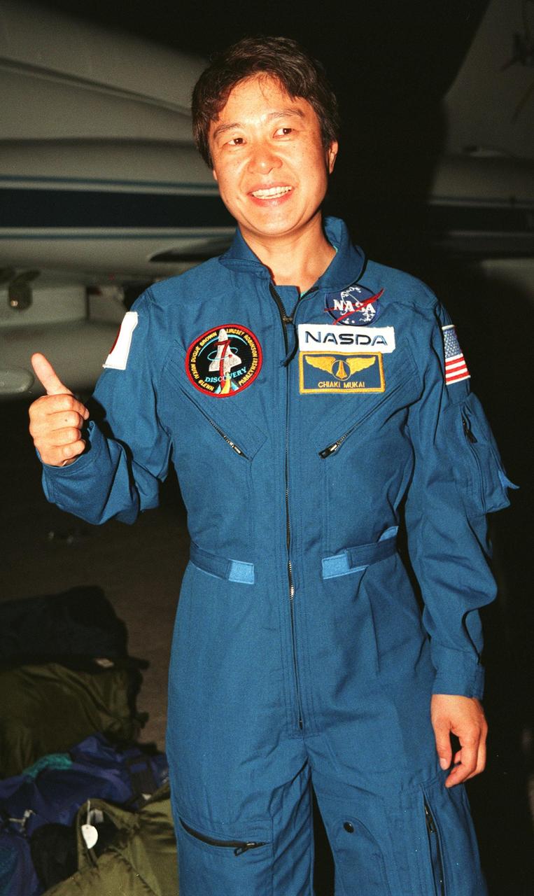
STS-95 Payload Specialist Chiaki Mukai, representing the National Space Development Agency of Japan (NASDA), gives a thumbs up after her arrival aboard a T-38 jet aircraft at the Shuttle Landing Facility at KSC. Mukai and the rest of the crew are at KSC to participate in a Terminal Countdown Demonstration Test (TCDT). The TCDT includes mission familiarization activities, training in emergency exit from the orbiter and launch pad, and a simulated main engine cut-off exercise. The other members on the mission are Mission Commander Curtis L. Brown, Pilot Steven W. Lindsey; Mission Specialists Scott E. Parazynski, Stephen K. Robinson, and Pedro Duque of Spain, representing the European Space Agency (ESA); and Payload Specialist John H. Glenn Jr., senator from Ohio. The STS-95 mission, scheduled for liftoff on Oct. 29, includes research payloads such as the Spartan solar-observing deployable spacecraft, the Hubble Space Telescope Orbital Systems Test Platform, the International Extreme Ultraviolet Hitchhiker, as well as the SPACEHAB single module with experiments on space flight and the aging process
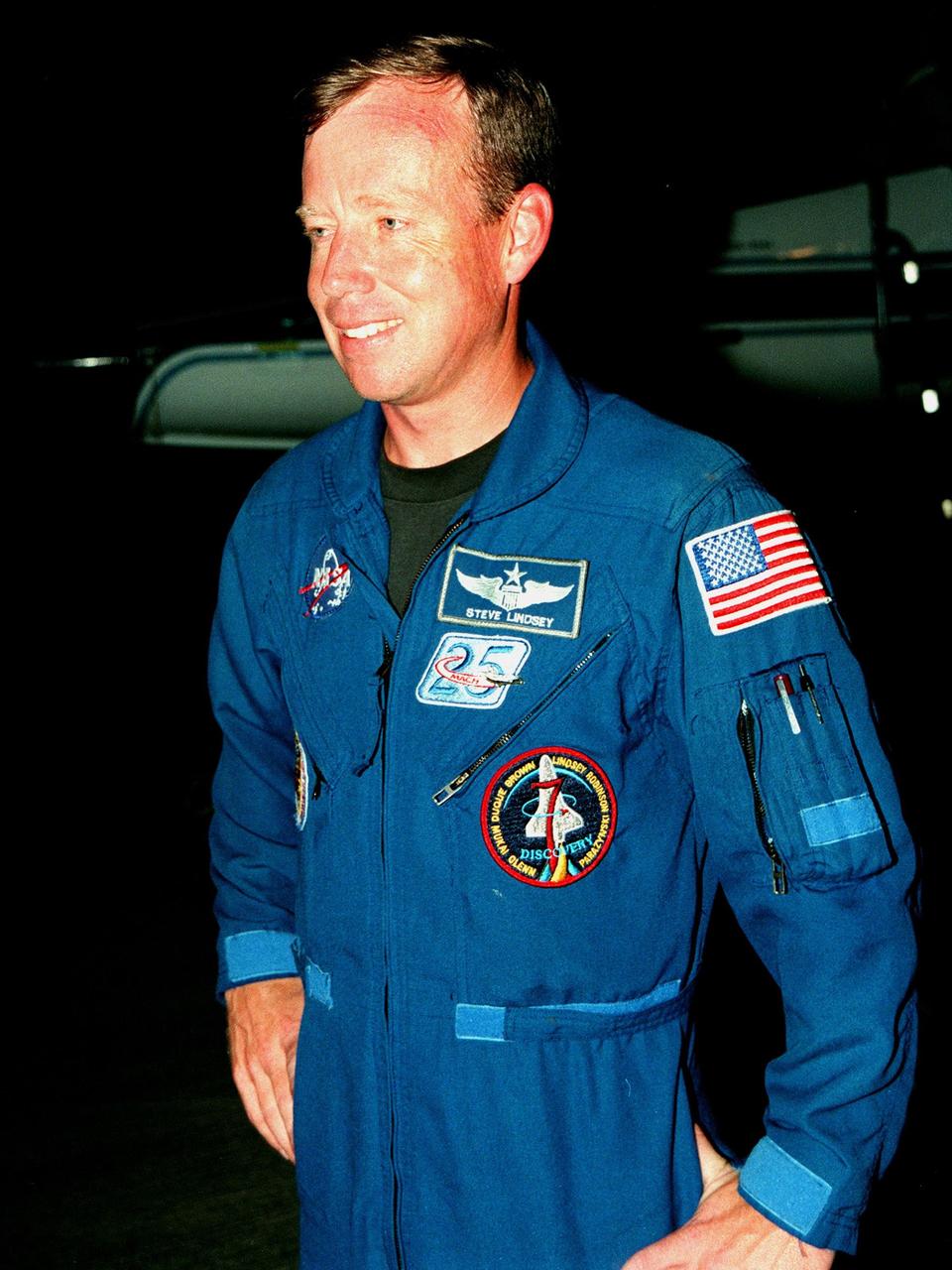
STS-95 Pilot Steven W. Lindsey smiles after his arrival aboard a T-38 jet aircraft at the Shuttle Landing Facility at KSC. The STS-95 crew are at KSC to participate in a Terminal Countdown Demonstration Test (TCDT). The TCDT includes mission familiarization activities, training in emergency exit from the orbiter and launch pad, and a simulated main engine cut-off exercise. The other members on the mission are Mission Commander Curtis L. Brown, Mission Specialists Scott E. Parazynski, Stephen K. Robinson, and Pedro Duque of Spain, representing the European Space Agency (ESA); and Payload Specialists John H. Glenn Jr., senator from Ohio, and Chiaki Mukai, representing the National Space Development Agency of Japan (NASDA). The STS-95 mission, scheduled for liftoff on Oct. 29, includes research payloads such as the Spartan solar-observing deployable spacecraft, the Hubble Space Telescope Orbital Systems Test Platform, the International Extreme Ultraviolet Hitchhiker, as well as the SPACEHAB single module with experiments on space flight and the aging process
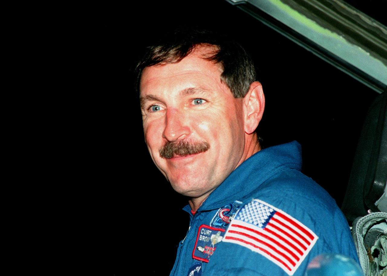
STS-95 Mission Commander Curtis L. Brown arrives aboard a T-38 jet aircraft at the Shuttle Landing Facility at KSC to participate in a Terminal Countdown Demonstration Test (TCDT). Mission launch is scheduled for liftoff on Oct. 29, 1998. The TCDT includes mission familiarization activities, training in emergency exit from the orbiter and launch pad, and a simulated main engine cut-off exercise. Other crew members on the mission are Pilot Steven W. Lindsey; Mission Specialists Scott E. Parazynski, Stephen K. Robinson, and Pedro Duque of Spain, representing the European Space Agency (ESA); and Payload Specialist Chiaki Mukai, representing the National Space Development Agency of Japan (NASDA). The STS-95 mission includes research payloads such as the Spartan solar-observing deployable spacecraft, the Hubble Space Telescope Orbital Systems Test Platform, the International Extreme Ultraviolet Hitchhiker, as well as the SPACEHAB single module with experiments on space flight and the aging process
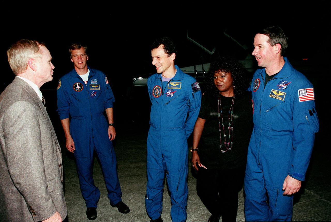
(Left to right) Center Director Roy Bridges welcomes STS-95 Mission Specialists Scott E. Parazynski, Pedro Duque of Spain, representing the European Space Agency (ESA), and Stephen K. Robinson (far right) after their arrival aboard T-38 jet aircraft at the Shuttle Landing Facility at KSC. Standing between Duque and Robinson is Dolores Green, NASA. The STS-95 crew are at KSC to participate in a Terminal Countdown Demonstration Test (TCDT). The TCDT includes mission familiarization activities, training in emergency exit from the orbiter and launch pad, and a simulated main engine cut-off exercise. The other members on the mission are Mission Commander Curtis L. Brown, Pilot Steven W. Lindsey; and Payload Specialists Chiaki Mukai, representing the National Space Development Agency of Japan (NASDA), and John H. Glenn Jr., senator from Ohio. The STS-95 mission, scheduled for liftoff on Oct. 29, includes research payloads such as the Spartan solar-observing deployable spacecraft, the Hubble Space Telescope Orbital Systems Test Platform, the International Extreme Ultraviolet Hitchhiker, as well as the SPACEHAB single module with experiments on space flight and the aging process

Center Director Roy Bridges (left) greets STS-95 Mission Commander Curtis L. Brown after his arrival on a T-38 jet aircraft at the Shuttle Landing Facility at KSC. Payload Specialist John H. Glenn Jr., a senator from Ohio, is at the right. Glenn arrived with Brown. They and the rest of the crew are at KSC to participate in a Terminal Countdown Demonstration Test (TCDT). The TCDT includes mission familiarization activities, training in emergency exit from the orbiter and launch pad, and a simulated main engine cut-off exercise. Other crew members on the mission are Pilot Steven W. Lindsey; Mission Specialists Scott E. Parazynski, Stephen K. Robinson, and Pedro Duque of Spain, representing the European Space Agency (ESA); and Payload Specialist Chiaki Mukai, representing the National Space Development Agency of Japan (NASDA). The STS-95 mission includes research payloads such as the Spartan solar-observing deployable spacecraft, the Hubble Space Telescope Orbital Systems Test Platform, the International Extreme Ultraviolet Hitchhiker, as well as the SPACEHAB single module with experiments on space flight and the aging process
Center Director Roy Bridges (left) greets STS-95 Payload Specialist John H. Glenn Jr. after his arrival on a T-38 jet aircraft at the Shuttle Landing Facility at KSC. Glenn, a senator from Ohio, and the rest of the crew are at KSC to participate in a Terminal Countdown Demonstration Test (TCDT). The TCDT includes mission familiarization activities, training in emergency exit from the orbiter and launch pad, and a simulated main engine cut-off exercise. The other crew members on the mission are Mission Commander Curtis L. Brown; Pilot Steven W. Lindsey; Mission Specialists Scott E. Parazynski, Stephen K. Robinson, and Pedro Duque of Spain, representing the European Space Agency (ESA); and Payload Specialist Chiaki Mukai, representing the National Space Development Agency of Japan (NASDA). The STS-95 mission includes research payloads such as the Spartan solar-observing deployable spacecraft, the Hubble Space Telescope Orbital Systems Test Platform, the International Extreme Ultraviolet Hitchhiker, as well as the SPACEHAB single module with experiments on space flight and the aging process
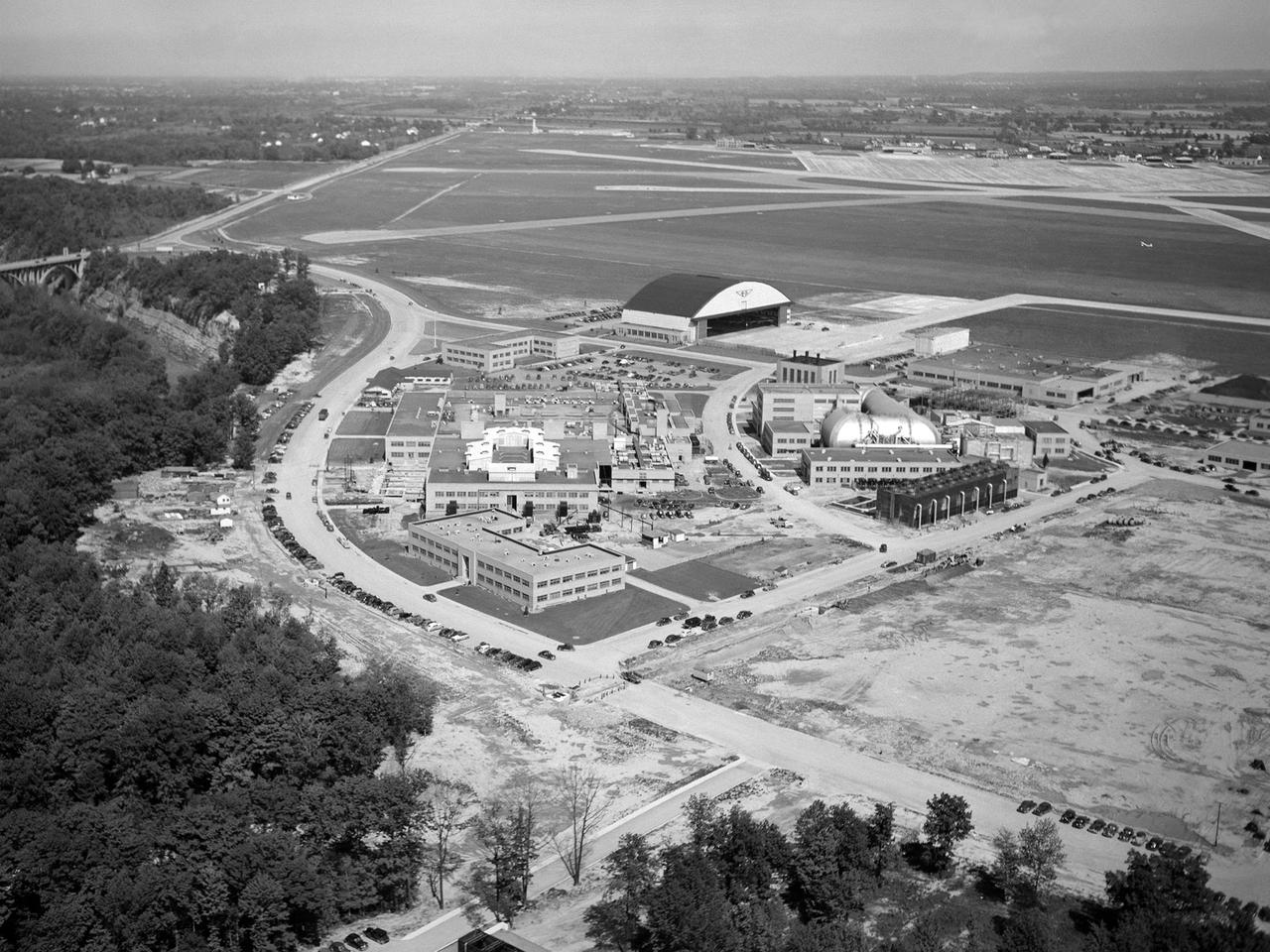
The National Advisory Committee for Aeronautics (NACA) Lewis Flight Propulsion Laboratory in Cleveland, Ohio as seen from the west in May 1946. The Cleveland Municipal Airport is located directly behind. The laboratory was built in the early 1940s to resolve problems associated with aircraft engines. The initial campus contained seven principal buildings: the Engine Research Building, hangar, Fuels and Lubricants Building, Administration Building, Engine Propeller Research Building, Altitude Wind Tunnel, and Icing Research Tunnel. These facilities and their associated support structures were located within an area occupying approximately one-third of the NACA’s property. After World War II ended, the NACA began adding new facilities to address different problems associated with the newer, more powerful engines and high speed flight. Between 1946 and 1955, four new world-class test facilities were built: the 8- by 6-Foot Supersonic Wind Tunnel, the Propulsion Systems Laboratory, the Rocket Engine Test Facility, and the 10- by 10-Foot Supersonic Wind Tunnel. These large facilities occupied the remainder of the NACA’s semicircular property. The Lewis laboratory expanded again in the late 1950s and early 1960s as the space program commenced. Lewis purchased additional land in areas adjacent to the original laboratory and acquired a large 9000-acre site located 60 miles to the west in Sandusky, Ohio. The new site became known as Plum Brook Station.

California, reveals the devastating effect of California's ongoing drought on Sierra Nevada conifer forests. The map will be used to help the U.S. Forest Service assess and respond to the impacts of increased tree mortality caused by the drought, particularly where wildlands meet urban areas within the Sierra National Forest. After several years of extreme drought, the highly stressed conifers (trees or bushes that produce cones and are usually green year-round) of the Sierra Nevada are now more susceptible to bark beetles (Dendroctonus spp.). While bark beetles killing trees in the Sierra Nevada is a natural phenomenon, the scale of mortality in the last couple of years is far greater than previously observed. The U.S. Forest Service is using recent airborne spectroscopic measurements from NASA's Airborne Visible/Infrared Imaging Spectrometer (AVIRIS) instrument aboard NASA's ER-2 aircraft, together with new advanced algorithms, to quantify this impact over this large region of rugged terrain. The high-altitude ER-2 aircraft is based at NASA's Armstrong Flight Research Center, Edwards, California. The image was created by scientists at the USFS's Pacific Southwest Region Remote Sensing Lab, McClellan, California, by performing a time series analysis of AVIRIS images. Scientists evaluated baseline tree mortality on public lands in the summer of 2015 using a machine learning algorithm called "random forest." This algorithm classifies the AVIRIS measurements as dominated by either shrubs, healthy trees or newly dead conifer trees. To quantify how much the amount of dead vegetation increased during the fall of 2015, the Forest Service scientists conducted an advanced spectral mixture analysis. This analysis evaluates each spectrum to determine the fraction of green vegetation, dead vegetation and soil. The full spectral range of AVIRIS is important to separate the signatures of soil and dead vegetation. To produce this comprehensive Sierra National Forest tree mortality map, the result from the summer of 2015 was evaluated to look for increases of more than 10 percent in dead vegetation during the fall of 2015. AVIRIS measures spectra of the Earth system to conduct advanced science research. These western U.S. AVIRIS measurements were acquired as part of NASA's Hyperspectral Infrared Imager (HyspIRI) preparatory airborne campaign. HyspIRI was one of the space missions suggested to NASA by the National Academy of Sciences in its 2007 decadal survey for Earth Science. In the future, HyspIRI could provide spectral and thermal measurements of this type globally for ecosystem research and additional science objectives. http://photojournal.jpl.nasa.gov/catalog/PIA20717
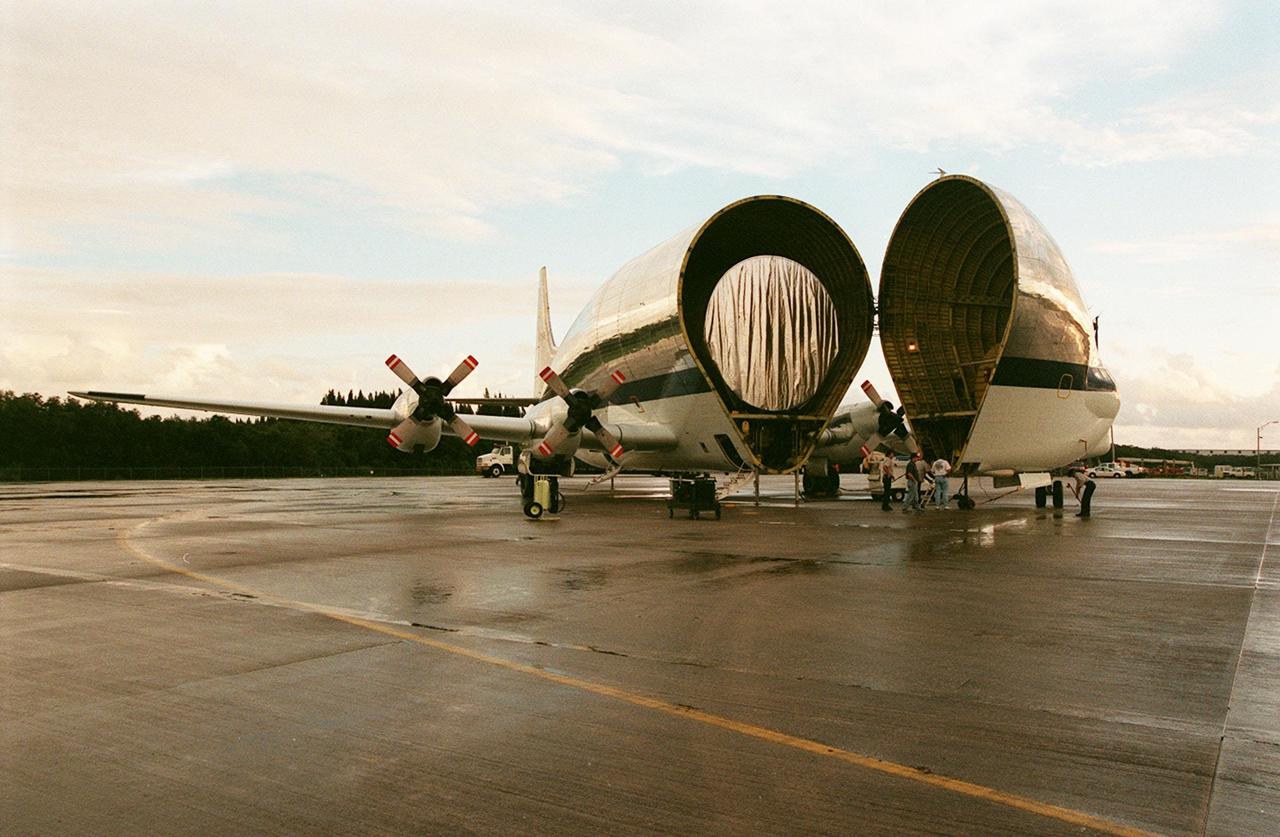
KENNEDY SPACE CENTER, FLA. -- At KSC's Shuttle Landing Facility, NASA's Super Guppy opens to reveal its cargo, the International Space Station's (ISS) S1 truss. Manufactured by the Boeing Co. in Huntington Beach, Calif., this component of the ISS is the first starboard (right-side) truss segment, whose main job is providing structural support for the orbiting research facility's radiator panels that cool the Space Station's complex power system. The S1 truss segment also will house communications systems, external experiment positions and other subsystems. Primarily constructed of aluminum, the truss segment is 45 feet long, 15 feet wide and 6 feet tall. When fully outfitted, it will weigh 31,137 pounds. The truss is slated for flight in 2001. The Super Guppy, with its 25-foot diameter fuselage designed to handle oversized loads, is well prepared to transport the truss and other ISS segments. Loading the Guppy is easy because of the unique "fold-away" nose of the aircraft that opens 110 degrees for cargo loading. A system of rails in the cargo compartment, used with either Guppy pallets or fixtures designed for specific cargo, makes cargo loading simple and efficient. Rollers mounted in the rails allow pallets or fixtures to be moved by an electric winch mounted beneath the cargo floor. Automatic hydraulic lock pins in each rail secure the pallet for flight. The truss is to be transferred to the Operations and Checkout Building
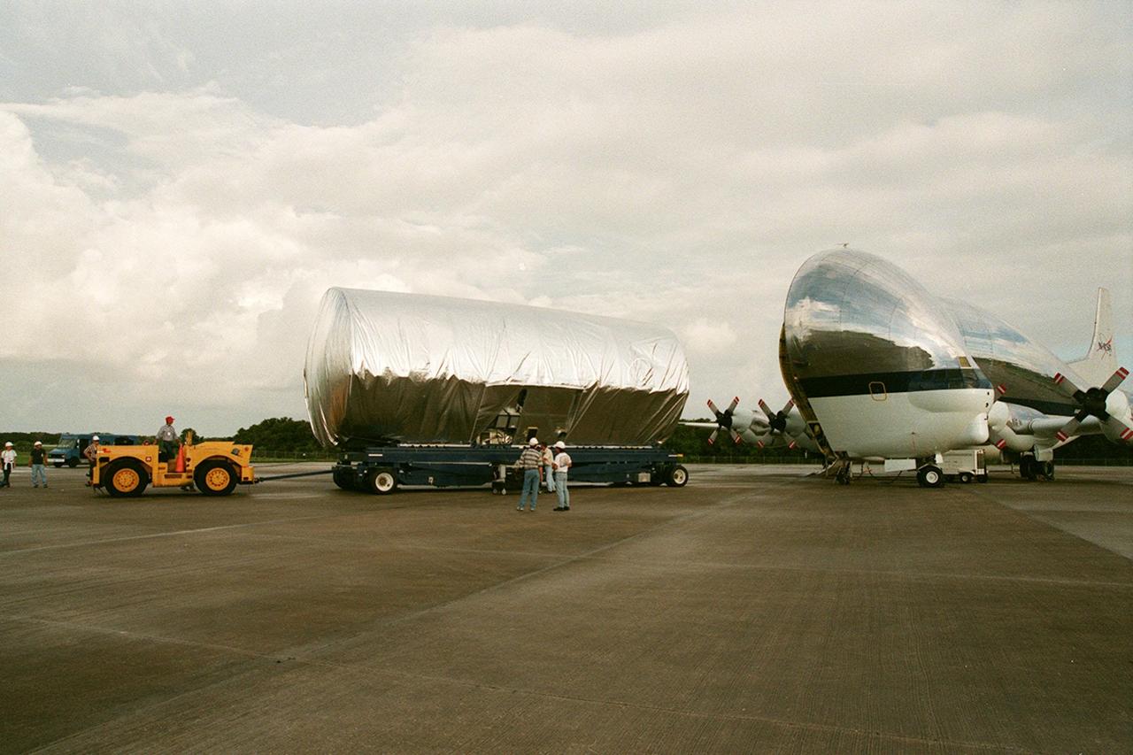
KENNEDY SPACE CENTER, FLA. -- At the Shuttle Landing Facility, the S1 truss, a segment of the International Space Station, is moved away from the Super Guppy that brought it to KSC from Marshall Space Flight Center. Manufactured by the Boeing Co. in Huntington Beach, Calif., this component of the ISS is the first starboard (right-side) truss segment, whose main job is providing structural support for the orbiting research facility's radiator panels that cool the Space Station's complex power system. The S1 truss segment also will house communications systems, external experiment positions and other subsystems. Primarily constructed of aluminum, the truss segment is 45 feet long, 15 feet wide and 6 feet tall. When fully outfitted, it will weigh 31,137 pounds. The truss is slated for flight in 2001. The Super Guppy, with its 25-foot diameter fuselage designed to handle oversized loads, is well prepared to transport the truss and other ISS segments. Loading the Guppy is easy because of the unique "fold-away" nose of the aircraft that opens 110 degrees for cargo loading. A system of rails in the cargo compartment, used with either Guppy pallets or fixtures designed for specific cargo, makes cargo loading simple and efficient. Rollers mounted in the rails allow pallets or fixtures to be moved by an electric winch mounted beneath the cargo floor. Automatic hydraulic lock pins in each rail secure the pallet for flight. The truss is being transferred to the Operations and Checkout Building
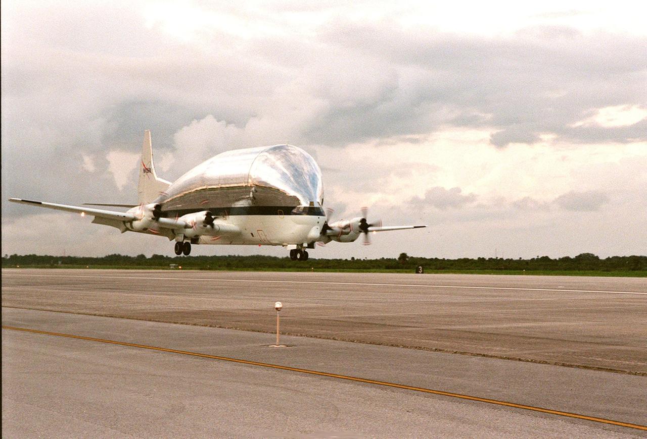
KENNEDY SPACE CENTER, FLA. -- NASA's Super Guppy airplane, with the International Space Station's (ISS) S1 truss aboard, arrives at KSC's Shuttle Landing Facility from Marshall Space Flight Center. Manufactured by the Boeing Co. in Huntington Beach, Calif., this component of the ISS is the first starboard (right-side) truss segment, whose main job is providing structural support for the orbiting research facility's radiator panels that cool the Space Station's complex power system. The S1 truss segment also will house communications systems, external experiment positions and other subsystems. Primarily constructed of aluminum, the truss segment is 45 feet long, 15 feet wide and 6 feet tall. When fully outfitted, it will weigh 31,137 pounds. The truss is slated for flight in 2001. The Super Guppy, with its 25-foot diameter fuselage designed to handle oversized loads, is well prepared to transport the truss and other ISS segments. Loading the Guppy is easy because of the unique "fold-away" nose of the aircraft that opens 110 degrees for cargo loading. A system of rails in the cargo compartment, used with either Guppy pallets or fixtures designed for specific cargo, makes cargo loading simple and efficient. Rollers mounted in the rails allow pallets or fixtures to be moved by an electric winch mounted beneath the cargo floor. Automatic hydraulic lock pins in each rail secure the pallet for flight. The truss is to be moved to the Operations and Checkout Building
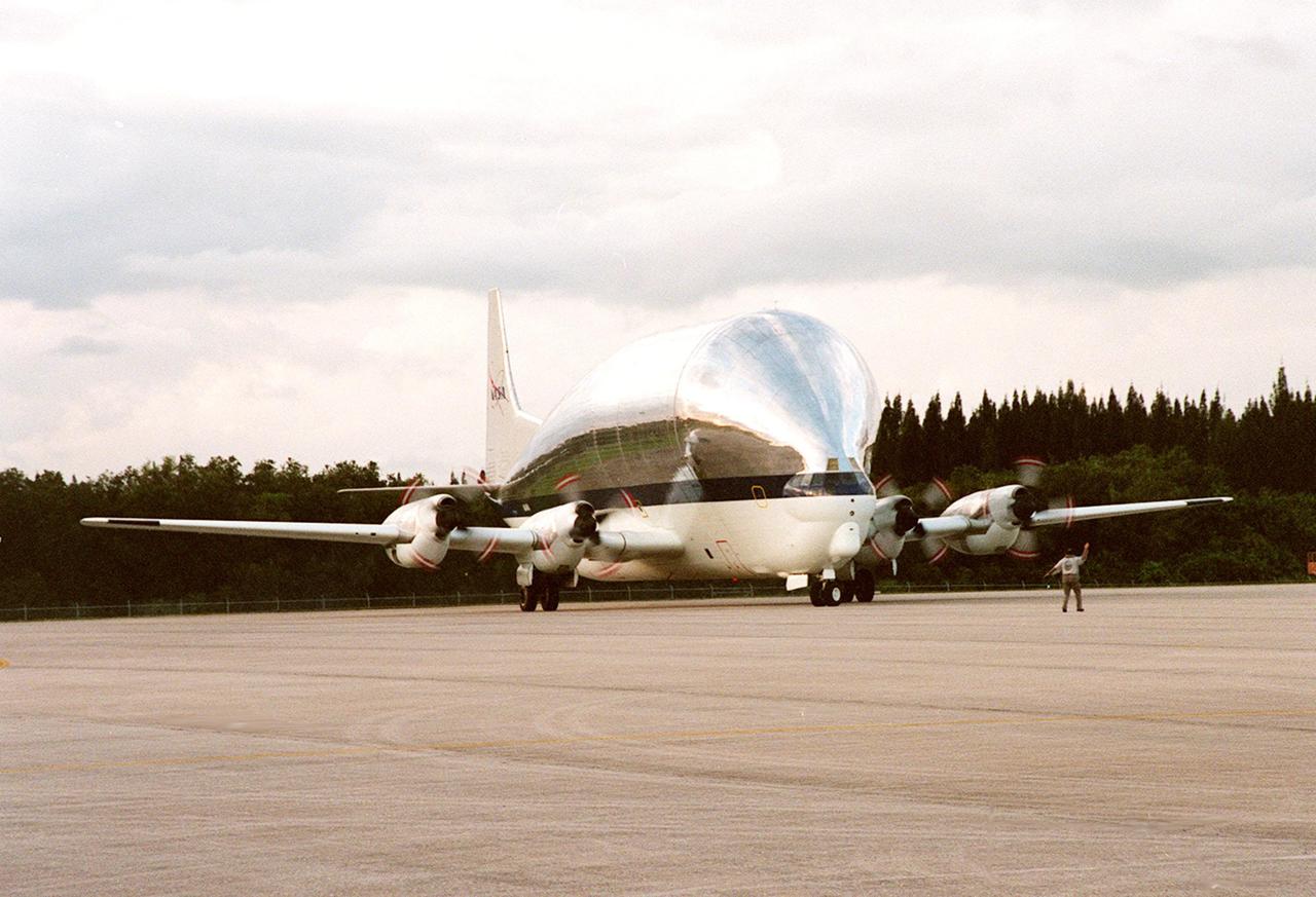
KENNEDY SPACE CENTER, FLA. -- NASA's Super Guppy airplane, with the International Space Station's (ISS) S1 truss aboard, rolls to a stop at KSC's Shuttle Landing Facility. Manufactured by the Boeing Co. in Huntington Beach, Calif., this component of the ISS is the first starboard (right-side) truss segment, whose main job is providing structural support for the orbiting research facility's radiator panels that cool the Space Station's complex power system. The S1 truss segment also will house communications systems, external experiment positions and other subsystems. Primarily constructed of aluminum, the truss segment is 45 feet long, 15 feet wide and 6 feet tall. When fully outfitted, it will weigh 31,137 pounds. The truss is slated for flight in 2001. The Super Guppy, with its 25-foot diameter fuselage designed to handle oversized loads, is well prepared to transport the truss and other ISS segments. Loading the Guppy is easy because of the unique "fold-away" nose of the aircraft that opens 110 degrees for cargo loading. A system of rails in the cargo compartment, used with either Guppy pallets or fixtures designed for specific cargo, makes cargo loading simple and efficient. Rollers mounted in the rails allow pallets or fixtures to be moved by an electric winch mounted beneath the cargo floor. Automatic hydraulic lock pins in each rail secure the pallet for flight. The truss is to be transferred to the Operations and Checkout Building

Heimdal Glacier in southern Greenland, in an image captured on Oct. 13, 2015, from NASA Langley Research Center's Falcon 20 aircraft flying 33,000 feet above mean sea level. NASA’s Operation IceBridge, an airborne survey of polar ice, recently finalized two overlapping campaigns at both of Earth’s poles. Down south, the mission observed a big drop in the height of two glaciers situated in the Antarctic Peninsula, while in the north it collected much needed measurements of the status of land and sea ice at the end of the Arctic summer melt season. This was the first time in its seven years of operations that IceBridge carried out parallel flights in the Arctic and Antarctic. Every year, the mission flies to the Arctic in the spring and to Antarctica in the fall to keep collect an uninterrupted record of yearly changes in the height of polar ice. Read more: <a href="http://www.nasa.gov/feature/goddard/nasa-s-operation-icebridge-completes-twin-polar-campaigns" rel="nofollow">www.nasa.gov/feature/goddard/nasa-s-operation-icebridge-c...</a> Credits: NASA/Goddard/John Sonntag <b><a href="http://www.nasa.gov/audience/formedia/features/MP_Photo_Guidelines.html" rel="nofollow">NASA image use policy.</a></b> <b><a href="http://www.nasa.gov/centers/goddard/home/index.html" rel="nofollow">NASA Goddard Space Flight Center</a></b> enables NASA’s mission through four scientific endeavors: Earth Science, Heliophysics, Solar System Exploration, and Astrophysics. Goddard plays a leading role in NASA’s accomplishments by contributing compelling scientific knowledge to advance the Agency’s mission. <b>Follow us on <a href="http://twitter.com/NASAGoddardPix" rel="nofollow">Twitter</a></b> <b>Like us on <a href="http://www.facebook.com/pages/Greenbelt-MD/NASA-Goddard/395013845897?ref=tsd" rel="nofollow">Facebook</a></b> <b>Find us on <a href="http://instagrid.me/nasagoddard/?vm=grid" rel="nofollow">Instagram</a></b>
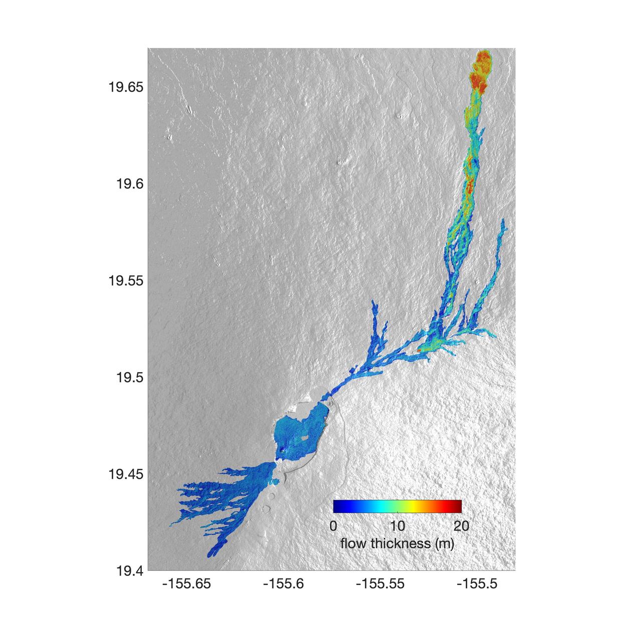
The world's largest active volcano – Hawaii's Mauna Loa – had been quiet for 38 years. But in 2022, the volcano began to stir, showing increased numbers of small earthquakes and subtle swelling of certain land surfaces in September. On November 27, fountains of lava began spurting from the mountain's Northeast Rift Zone and streams of molten rock flowed to the north. Ten days into the eruption, a NASA aircraft conducted its first flight over the erupting volcano. It carried NASA's Uninhabited Aerial Vehicle Synthetic Aperture Radar (UAVSAR) system, which was used to map the volcano's topography in fine detail with a Ka-band instrument called GLISTIN-A. Teams from NASA's Jet Propulsion Laboratory and the United States Geological Survey (USGS) used data from that sensor to map the thickness of those flows during a series of flights on December 7, 8, and 10. The map above shows the thickness of the lava flows during the flight on December 7, the day before USGS scientists noticed a significant decline in the pace of the eruption. A few days later, they declared the eruption had stopped. The map shows the thickness of the lava flows in the summit caldera, where the eruption began, and of lava flows on Mauna Loa's northeastern flank. The color variation from blue to orange indicates increasing lava flow thickness. A maximum thickness of roughly 25 meters (82 feet) is shown, though values exceeding 40 meters (131 feet) were observed in some areas. The thickening at the northern end of the flow is due to lava accumulating away from the vent, along with a flattening of the terrain at the saddle between the Mauna Loa and Mauna Kea volcanoes. By comparing to pre-eruption maps of this area's topography, including GLISTIN-A data collected in 2017, the USGS researchers were able to calculate the size and volume of the lava flow. Over the roughly 14-day eruption, Mauna Loa erupted more than 8.8 billion cubic feet (230 million cubic meters) along a lava flow that extended up to 16.5 miles (19.5 kilometers) from the vent, according to the USGS. The UAVSAR operates from a pod mounted beneath a crewed Gulfstream III jet from NASA's Armstrong Flight Research Center in California. Repeated topographic maps generated with each flight reveal the progression and thickening of lava with time – important information for scientific understanding of volcano processes and for emergency response. For the Mauna Loa science flights, the instrument suite featured an additional state-of-the-art imaging tool: the synthetic aperture radar-fusion optical short-wave infrared (SAR-Fusion Optical/SWIR) camera system. SAR-Fusion collects data over the same ground swath as GLISTIN-A to map land surface changes using optical/SWIR photogrammetry methods. GLISTIN-A was designed to provide all-weather, high-resolution surface topography not available through existing lidar or radar sensors. GLISTIN-A was originally demonstrated as a new radar technique for mapping ice surfaces. Science demonstration flights began in 2013 over alpine glaciers and sea ice in Alaska, and a floodplain in California. Its applications have since expanded to other areas, such as snow accumulation and volcano dynamics. The first time the instrument was deployed for volcano response was in 2018 during the three-month eruption of Kilauea. The success of that operation paved the way for deployment to Mauna Loa. https://photojournal.jpl.nasa.gov/catalog/PIA25526
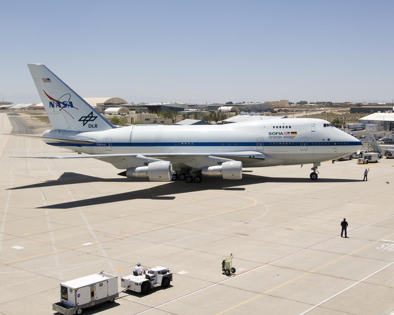
NASA's SOFIA 747SP bearing a German-built 2.5-meter infrared telescope in its rear fuselage taxis up to NASA Dryden's ramp after a ferry flight from Waco, Texas. NASA's Stratospheric Observatory for Infrared Astronomy, or SOFIA, arrived at NASA's Dryden Flight Research Center at Edwards Air Force Base, Calif. on May 31, 2007. The heavily modified Boeing 747SP was ferried to Dryden from Waco, Texas, where L-3 Communications Integrated Systems installed a German-built 2.5-meter infrared telescope and made other major modifications over the past several years. SOFIA is scheduled to undergo installation and integration of mission systems and a multi-phase flight test program at Dryden over the next three years that is expected to lead to a full operational capability to conduct astronomy missions in about 2010. During its expected 20-year lifetime, SOFIA will be capable of "Great Observatory" class astronomical science, providing astronomers with access to the visible, infrared and sub-millimeter spectrum with optimized performance in the mid-infrared to sub-millimeter range.

NASA's Stratospheric Observatory for Infrared Astronomy (SOFIA) Boeing 747SP flies over NASA's Dryden Flight Research Center after a ferry flight from Waco, Texas. NASA's Stratospheric Observatory for Infrared Astronomy, or SOFIA, arrived at NASA's Dryden Flight Research Center at Edwards Air Force Base, Calif. on May 31, 2007. The heavily modified Boeing 747SP was ferried to Dryden from Waco, Texas, where L-3 Communications Integrated Systems installed a German-built 2.5-meter infrared telescope and made other major modifications over the past several years. SOFIA is scheduled to undergo installation and integration of mission systems and a multi-phase flight test program at Dryden over the next three years that is expected to lead to a full operational capability to conduct astronomy missions in about 2010. During its expected 20-year lifetime, SOFIA will be capable of "Great Observatory" class astronomical science, providing astronomers with access to the visible, infrared and sub-millimeter spectrum with optimized performance in the mid-infrared to sub-millimeter range.
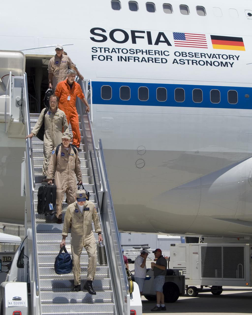
The SOFIA flight crew, consisting of Co-pilot Gordon Fullerton; DFRC, Pilot Bill Brocket; DFRC, Test Conductor Marty Trout; DFRC, Test Engineer Don Stonebrook; L-3, and Flight Engineer Larry Larose; JSC, descend the stairs after ferrying the 747SP airborne observatory from Waco, Texas, to its new home at NASA's Dryden Flight Research Center in California. NASA's Stratospheric Observatory for Infrared Astronomy, or SOFIA, arrived at NASA's Dryden Flight Research Center at Edwards Air Force Base, Calif. on May 31, 2007. The heavily modified Boeing 747SP was ferried to Dryden from Waco, Texas, where L-3 Communications Integrated Systems installed a German-built 2.5-meter infrared telescope and made other major modifications over the past several years. SOFIA is scheduled to undergo installation and integration of mission systems and a multi-phase flight test program at Dryden over the next three years that is expected to lead to a full operational capability to conduct astronomy missions in about 2010. During its expected 20-year lifetime, SOFIA will be capable of "Great Observatory" class astronomical science, providing astronomers with access to the visible, infrared and sub-millimeter spectrum with optimized performance in the mid-infrared to sub-millimeter range.
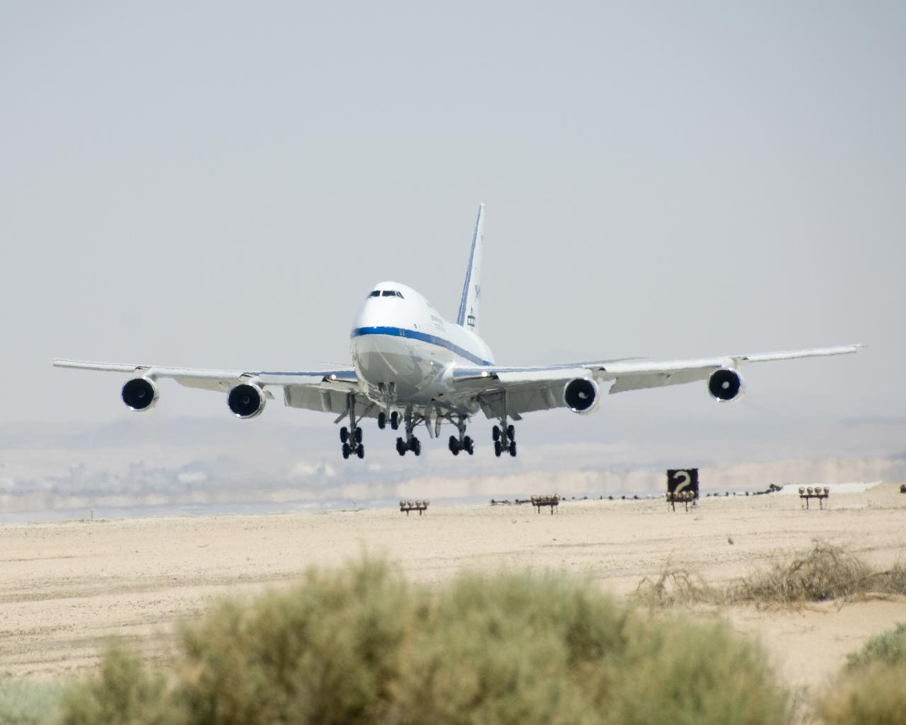
NASA's Stratospheric Observatory for Infrared Astronomy (SOFIA) Boeing 747SP flares for landing at Edwards AFB after a ferry flight from Waco, Texas. NASA's Stratospheric Observatory for Infrared Astronomy, or SOFIA, arrived at NASA's Dryden Flight Research Center at Edwards Air Force Base, Calif. on May 31, 2007. The heavily modified Boeing 747SP was ferried to Dryden from Waco, Texas, where L-3 Communications Integrated Systems installed a German-built 2.5-meter infrared telescope and made other major modifications over the past several years. SOFIA is scheduled to undergo installation and integration of mission systems and a multi-phase flight test program at Dryden over the next three years that is expected to lead to a full operational capability to conduct astronomy missions in about 2010. During its expected 20-year lifetime, SOFIA will be capable of "Great Observatory" class astronomical science, providing astronomers with access to the visible, infrared and sub-millimeter spectrum with optimized performance in the mid-infrared to sub-millimeter range.

NASA's SOFIA airborne observatory lands at Edwards AFB after being flown from Waco, Texas to NASA Dryden for systems installation, integration and flight test. NASA's Stratospheric Observatory for Infrared Astronomy, or SOFIA, arrived at NASA's Dryden Flight Research Center at Edwards Air Force Base, Calif. on May 31, 2007. The heavily modified Boeing 747SP was ferried to Dryden from Waco, Texas, where L-3 Communications Integrated Systems installed a German-built 2.5-meter infrared telescope and made other major modifications over the past several years. SOFIA is scheduled to undergo installation and integration of mission systems and a multi-phase flight test program at Dryden over the next three years that is expected to lead to a full operational capability to conduct astronomy missions in about 2010. During its expected 20-year lifetime, SOFIA will be capable of "Great Observatory" class astronomical science, providing astronomers with access to the visible, infrared and sub-millimeter spectrum with optimized performance in the mid-infrared to sub-millimeter range.

Scientists and crew with NASA’s Operation IceBridge, which makes annual aerial surveys of polar ice, are wrapping up their seventh campaign over the Arctic. In spring 2015, the team began using a different research aircraft—an adapted C-130 Hercules. They also added four new high-priority targets in the rapidly changing region of northeast Greenland. Many of the flights, however, were routine. And that’s exactly the point; making measurements over the same path each year provides continuity between NASA’s Ice, Cloud, and Land Elevation Satellite (ICESat) missions—the first of which ended in 2009 and the second of which is scheduled for launch in 2017. Repeat measurements show how a landscape changes over time. One area that has been surveyed repeatedly is northern Greenland’s Ryder Glacier. This photograph, taken during the IceBridge flight on May 6, 2015, shows a large moulin—dozens of meters across—atop this glacier. Moulins are holes in the ice sheet that drain melt water from the ice sheet’s surface to the bottom or out to the sea. Scientists are working to figure out what happens to melt water once it enters a moulin. Read more: <a href="http://earthobservatory.nasa.gov/IOTD/view.php?id=85858&eocn=home&eoci=iotd_title" rel="nofollow">earthobservatory.nasa.gov/IOTD/view.php?id=85858&eocn...</a> Credit: <b><a href="http://www.earthobservatory.nasa.gov/" rel="nofollow"> NASA Earth Observatory</a></b> <b><a href="http://www.nasa.gov/audience/formedia/features/MP_Photo_Guidelines.html" rel="nofollow">NASA image use policy.</a></b> <b><a href="http://www.nasa.gov/centers/goddard/home/index.html" rel="nofollow">NASA Goddard Space Flight Center</a></b> enables NASA’s mission through four scientific endeavors: Earth Science, Heliophysics, Solar System Exploration, and Astrophysics. Goddard plays a leading role in NASA’s accomplishments by contributing compelling scientific knowledge to advance the Agency’s mission. <b>Follow us on <a href="http://twitter.com/NASAGoddardPix" rel="nofollow">Twitter</a></b> <b>Like us on <a href="http://www.facebook.com/pages/Greenbelt-MD/NASA-Goddard/395013845897?ref=tsd" rel="nofollow">Facebook</a></b> <b>Find us on <a href="http://instagrid.me/nasagoddard/?vm=grid" rel="nofollow">Instagram</a></b>