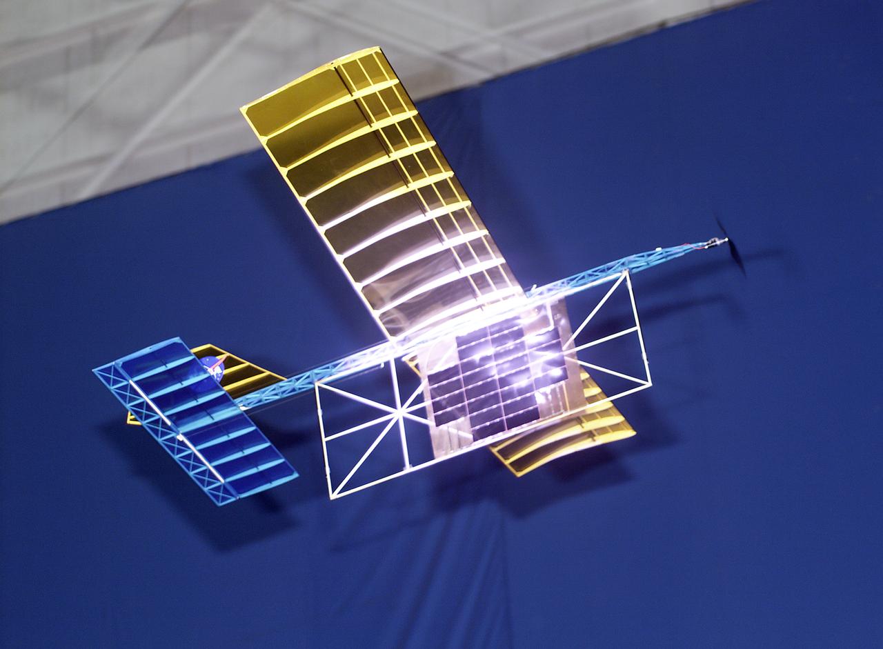
With a laser beam centered on its panel of photovoltaic cells, a lightweight model plane makes the first flight of an aircraft powered by a laser beam inside a building at NASA Marshall Space Flight Center.
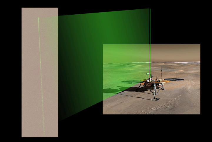
The Surface Stereo Imager camera aboard NASA Phoenix Mars Lander acquired a series of images of the laser beam in the Martian night sky. Bright spots in the beam are reflections from ice crystals in the low level ice-fog.
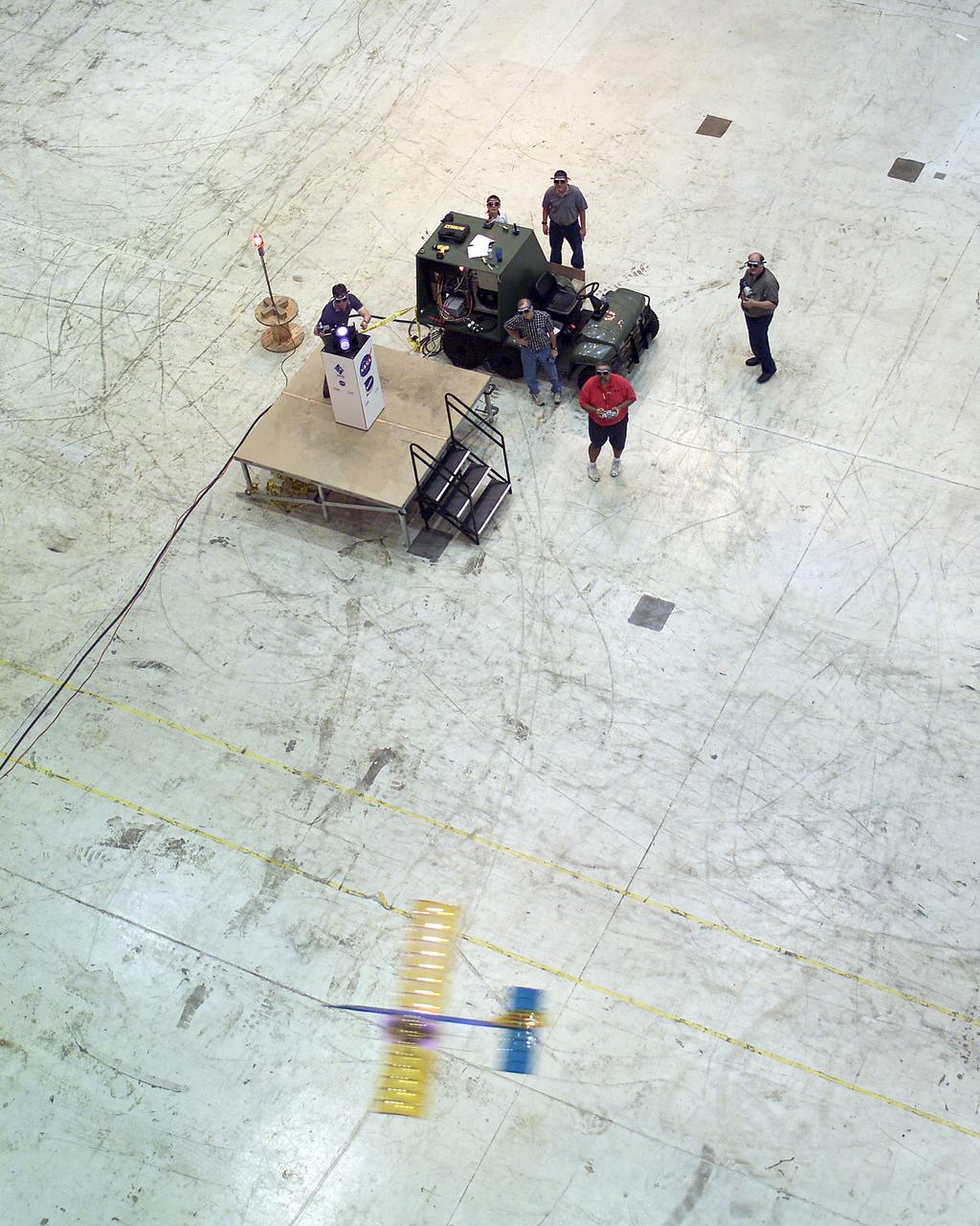
Powered by a laser beam directed at it from a center pedestal, a lightweight model plane makes the first flight of an aircraft powered by laser energy inside a building at NASA's Marshall Space Flight Center.
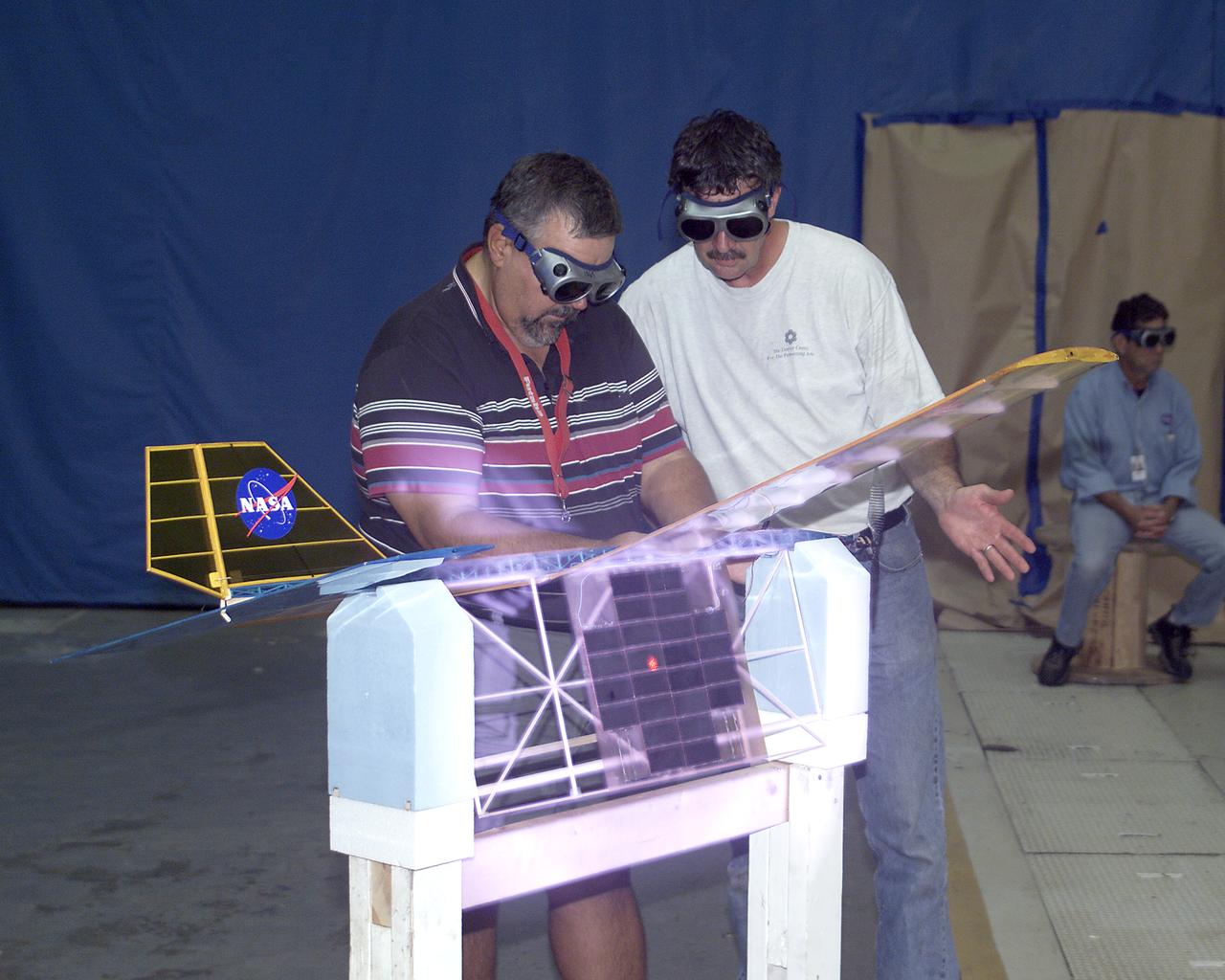
With a laser beam centered on its solar panel, a lightweight model aircraft is checked out by technician Tony Frakowiak and researcher Tim Blackwell before its power-beamed demonstration flight.
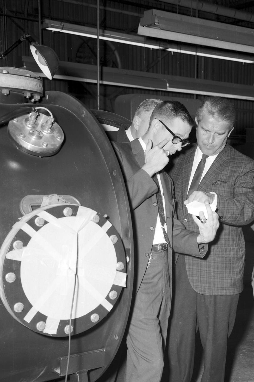
Dr. von Braun and party look at a laser beam component during a visit at the Marshall Space Flight Center Space Science Laboratory on August 28, 1967.
The ChemCam instrument for NASA Mars Science Laboratory mission uses a pulsed laser beam to vaporize a pinhead-size target, producing a flash of light from the ionized material plasma that can be analyzed to identify chemical elements in the target.

The ChemCam instrument for NASA Mars Science Laboratory mission uses a pulsed laser beam to vaporize a pinhead-size target, producing a flash of light from the ionized material plasma that can be analyzed to identify chemical elements in the target.
The SELENE Optics project was designed to send powerful laser beams into space to repower satellites and to recharge their batteries, as well as sending laser beams to the moon for the same purpose instead of relying on solar power. This project also was intended to be used for repowering extended space flights.
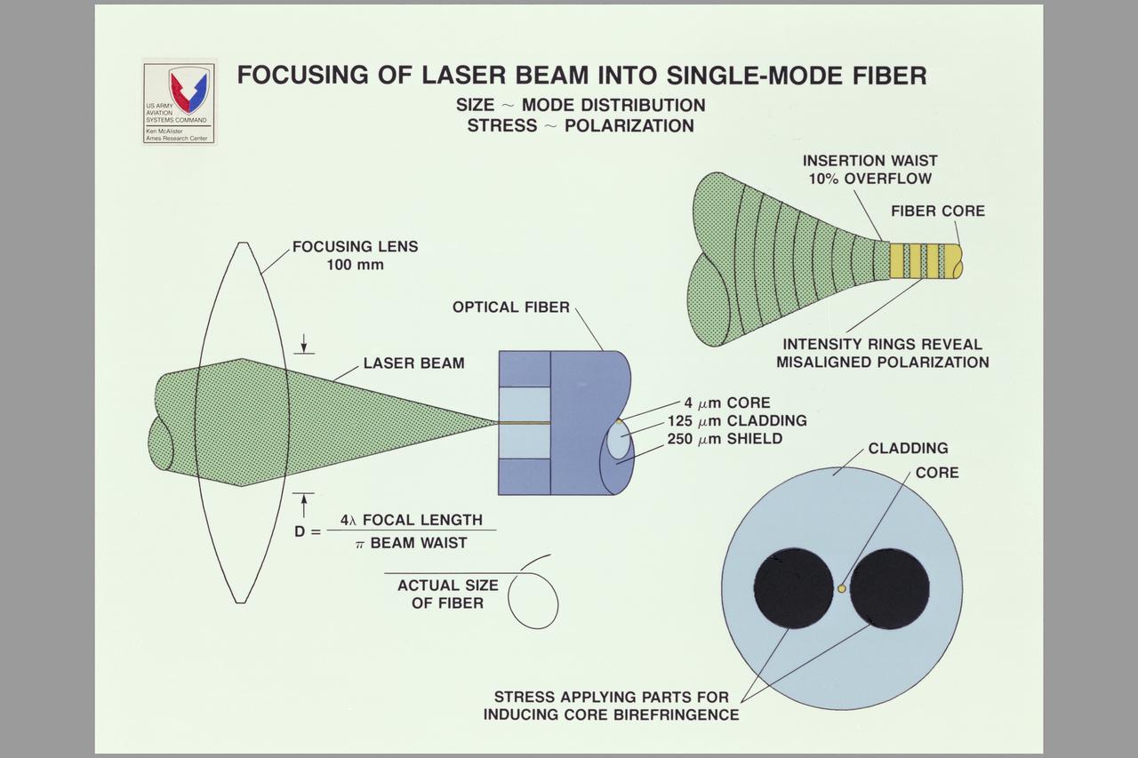
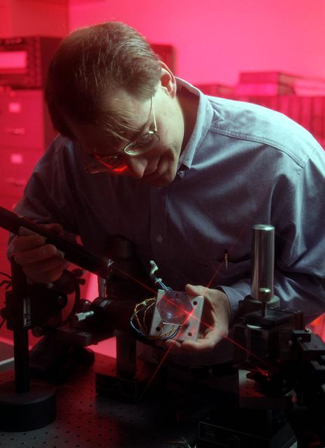
Graphics (McAlister) Army Aeroflightdynamics Directorate 3D Laser Velocimeter for Rotor Flow Studies: Focusing of Laser Beam into Single-Mode Fiber Composite.
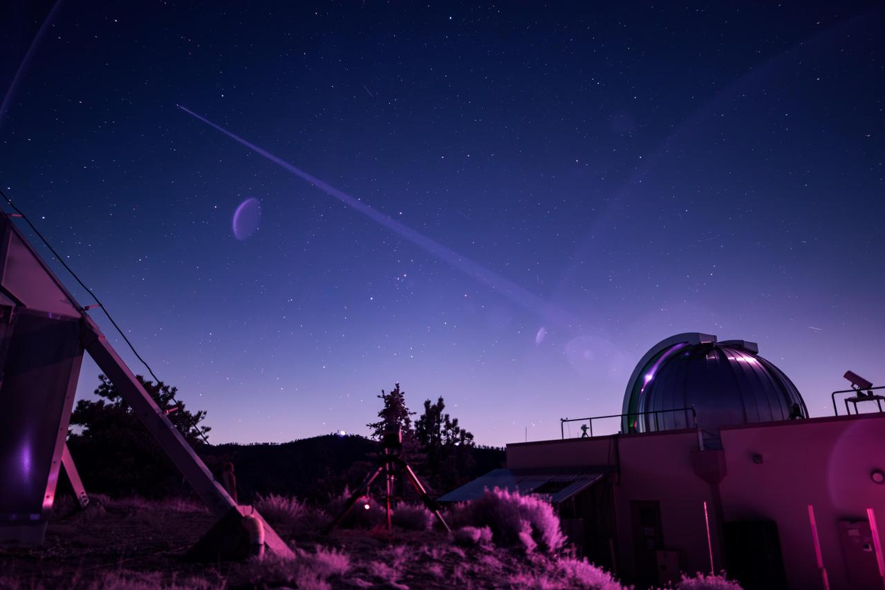
In this infrared photograph, the Optical Communications Telescope Laboratory (OCTL) at NASA Jet Propulsion Laboratory's Table Mountain Facility near Wrightwood, California, beams its eight-laser beacon (at a total power of 1.4 kilowatts) to the Deep Space Optical Communications (DSOC) flight laser transceiver aboard NASA's Psyche spacecraft. The photo was taken on June 2, 2025, when Psyche was about 143 million miles (230 million kilometers) from Earth. The faint purple crescent just left of center and near the laser beam is a lens flare caused by a bright light (out of frame) reflecting inside the camera lens. As the experiment's ground laser transmitter, OCTL transmits at an infrared wavelength of 1,064 nanometers from its 3.3-foot-aperture (1-meter) telescope. The telescope can also receive faint infrared photons (at a wavelength of 1,550 nanometers) from the 4-watt flight laser transceiver on Psyche. Neither infrared wavelength is easily absorbed or scattered by Earth's atmosphere, making both ideal for deep space optical communications. To receive the most distant signals from Psyche, the project enlisted the powerful 200-inch-aperture (5-meter) Hale Telescope at Caltech's Palomar Observatory in San Diego County, California, as its primary downlink station, which provided adequate light-collecting area to capture the faintest photons. Those photons were then directed to a cryogenically cooled superconducting high-efficiency detector array at the observatory where the information encoded in the photons could be processed. Managed by JPL, DSOC was designed to demonstrate that data encoded in laser photons could be reliably transmitted, received, and then decoded after traveling millions of miles from Earth out to Mars distances. Nearly two years after launching aboard the agency's Psyche mission in 2023, the demonstration completed its 65th and final "pass" on Sept. 2, 2025, sending a laser signal to Psyche and receiving the return signal from 218 million miles (350 million kilometers) away. https://photojournal.jpl.nasa.gov/catalog/PIA26661
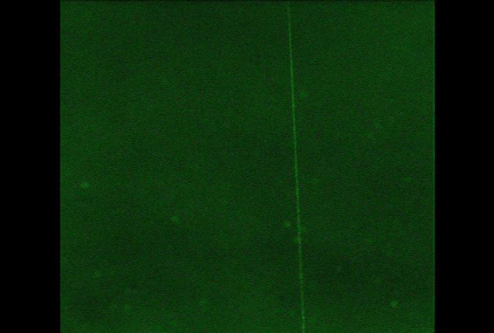
A laser beam from the Canadian-built lidar instrument on NASA Phoenix Mars Lander can be seen in this contrast-enhanced image taken by Phoenix Surface Stereo Imager on July 26, 2008, during early Martian morning hours of the 61st Martian day.
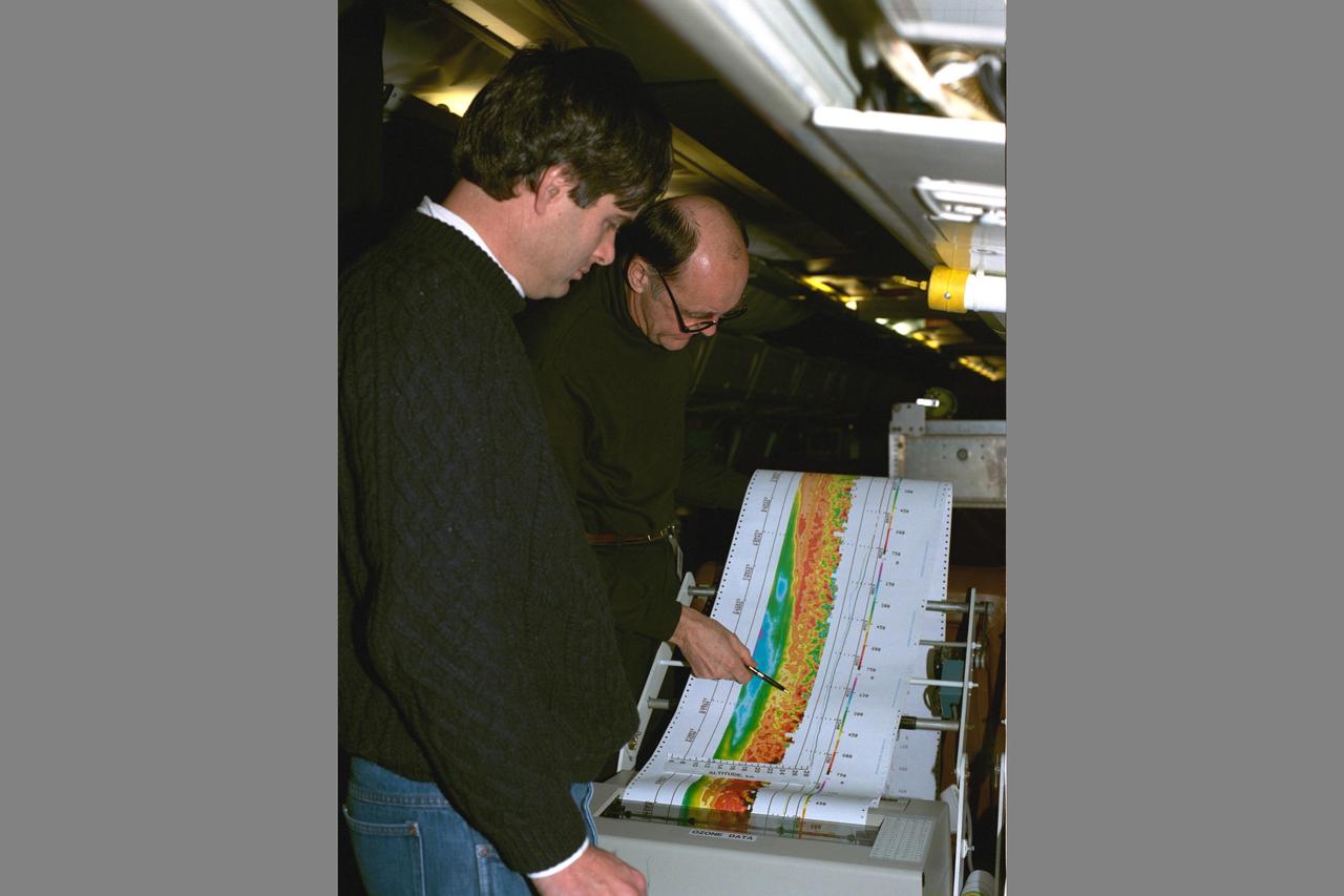
Arctic Ozone Expedition Stavanger Norway: Arlin Carter, NASA Langley Research Center, is shown here with colleague during flight collecting data on the laser ozone mapping experiment. This experiment uses laser beams to determine the extent of column ozone above the DC-8 flying laboratory on which the laser experiment flys.
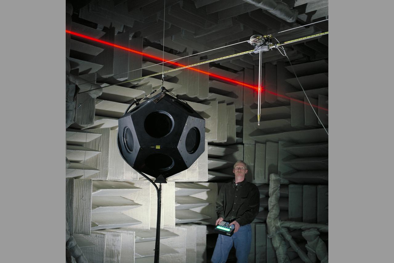
Traversing Microphone & Dodecahedron Loudspeaker (with pen lights - laser beams) in Anechoic Chamber with Chris Allen) Dedechedron meaning 12 sided polyhedron - polygon)
The Boussard Interstellar Ramjet engine concept uses interstellar hydrogen scooped up from its environment as the spacecraft passes by to provide propellant mass. The hydrogen is then ionized and then collected by an electromagentic field. In this image, an onboard laser is uded to heat the plasma, and the laser or electron beam is used to trigger fusion pulses thereby creating propulsion.
This infrared photograph shows the uplink laser beacon for NASA's Deep Space Optical Communications (DSOC) experiment beaming into the night sky from the Optical Communications Telescope Laboratory (OCTL) at NASA Jet Propulsion Laboratory's Table Mountain Facility near Wrightwood, California. Attached to the agency's Psyche spacecraft, the DSOC flight laser transceiver can receive and send data from Earth in encoded photons. As the experiment's ground laser transmitter, OCTL transmits at an infrared wavelength of 1,064 nanometers from its 3.3-foot-aperture (1-meter) telescope. The telescope can also receive faint infrared photons (at a wavelength of 1,550 nanometers) from the 4-watt flight laser transceiver on Psyche. Neither infrared wavelength is easily absorbed or scattered by Earth's atmosphere, making both ideal for deep space optical communications. To receive the most distant signals from Psyche, the project enlisted the powerful 200-inch-aperture (5-meter) Hale Telescope at Caltech's Palomar Observatory in San Diego County, California, as its primary downlink station, which provided adequate light-collecting area to capture the faintest photons. Those photons were then directed to a cryogenically cooled superconducting high-efficiency detector array at the observatory where the information encoded in the photons could be processed. Managed by JPL, DSOC was designed to demonstrate that data encoded in laser photons could be reliably transmitted, received, and then decoded after traveling millions of miles from Earth out to Mars distances. Nearly two years after launching aboard the agency's Psyche mission in 2023, the demonstration completed its 65th and final "pass" on Sept. 2, 2025, sending a laser signal to Psyche and receiving the return signal from 218 million miles (350 million kilometers) away. https://photojournal.jpl.nasa.gov/catalog/PIA26662
A team of NASA researchers from Marshall Space Flight Center (MSFC) and Dryden Flight Research center have proven that beamed light can be used to power an aircraft, a first-in-the-world accomplishment to the best of their knowledge. Using an experimental custom built radio-controlled model aircraft, the team has demonstrated a system that beams enough light energy from the ground to power the propeller of an aircraft and sustain it in flight. Special photovoltaic arrays on the plane, similar to solar cells, receive the light energy and convert it to electric current to drive the propeller motor. In a series of indoor flights this week at MSFC, a lightweight custom built laser beam was aimed at the airplane `s solar panels. The laser tracks the plane, maintaining power on its cells until the end of the flight when the laser is turned off and the airplane glides to a landing. The laser source demonstration represents the capability to beam more power to a plane so that it can reach higher altitudes and have a greater flight range without having to carry fuel or batteries, enabling an indefinite flight time. The demonstration was a collaborative effort between the Dryden Center at Edward's, California, where the aircraft was designed and built, and MSFC, where integration and testing of the laser and photovoltaic cells was done. Laser power beaming is a promising technology for consideration in new aircraft design and operation, and supports NASA's goals in the development of revolutionary aerospace technologies. Photographed with their invention are (from left to right): David Bushman and Tony Frackowiak, both of Dryden; and MSFC's Robert Burdine.
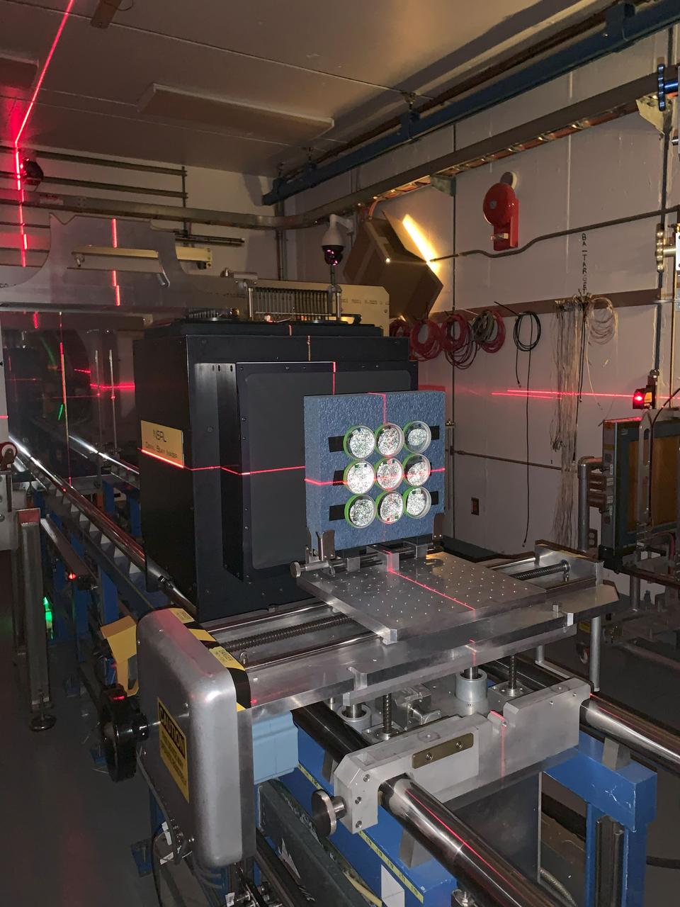
jsc2024e062109 (9/13/2024) ---The ANT1 Radiation Tolerance Experiment with Moss in Orbit on the Space Station (ARTEMOSS) plates are attached to the foam holder prepared for the ion beam run in the target room at the NASA Space Radiation Laboratory (NSRL), at the Brookhaven National Laboratory (BNL), with a visible laser used to center the beam placement. The ARTEMOSS investigation examines whether and how an Antarctic moss repairs damage caused by cosmic radiation and microgravity. Image courtesy of Agata Zupanska.
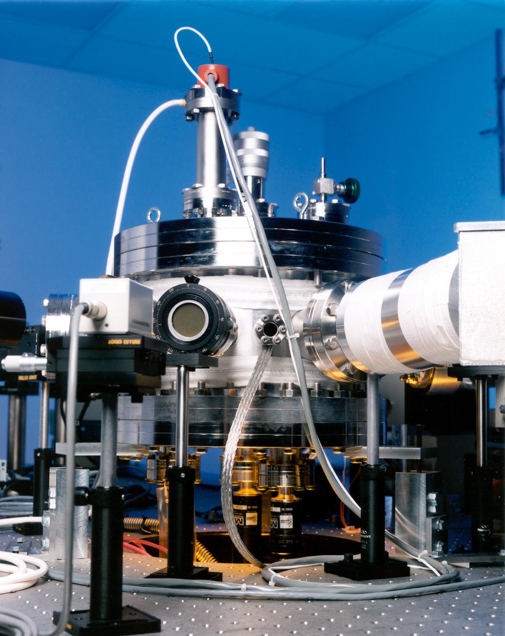
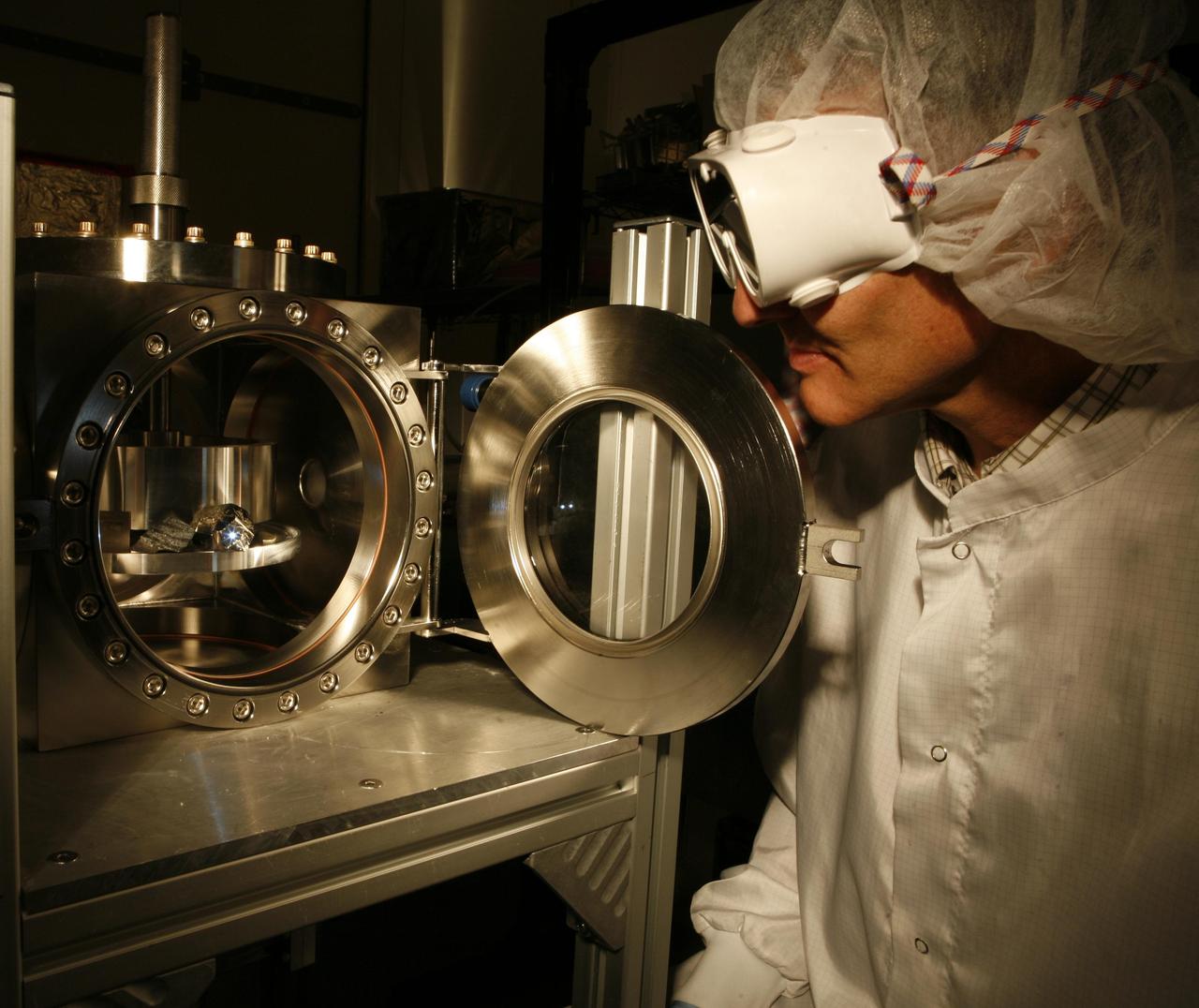
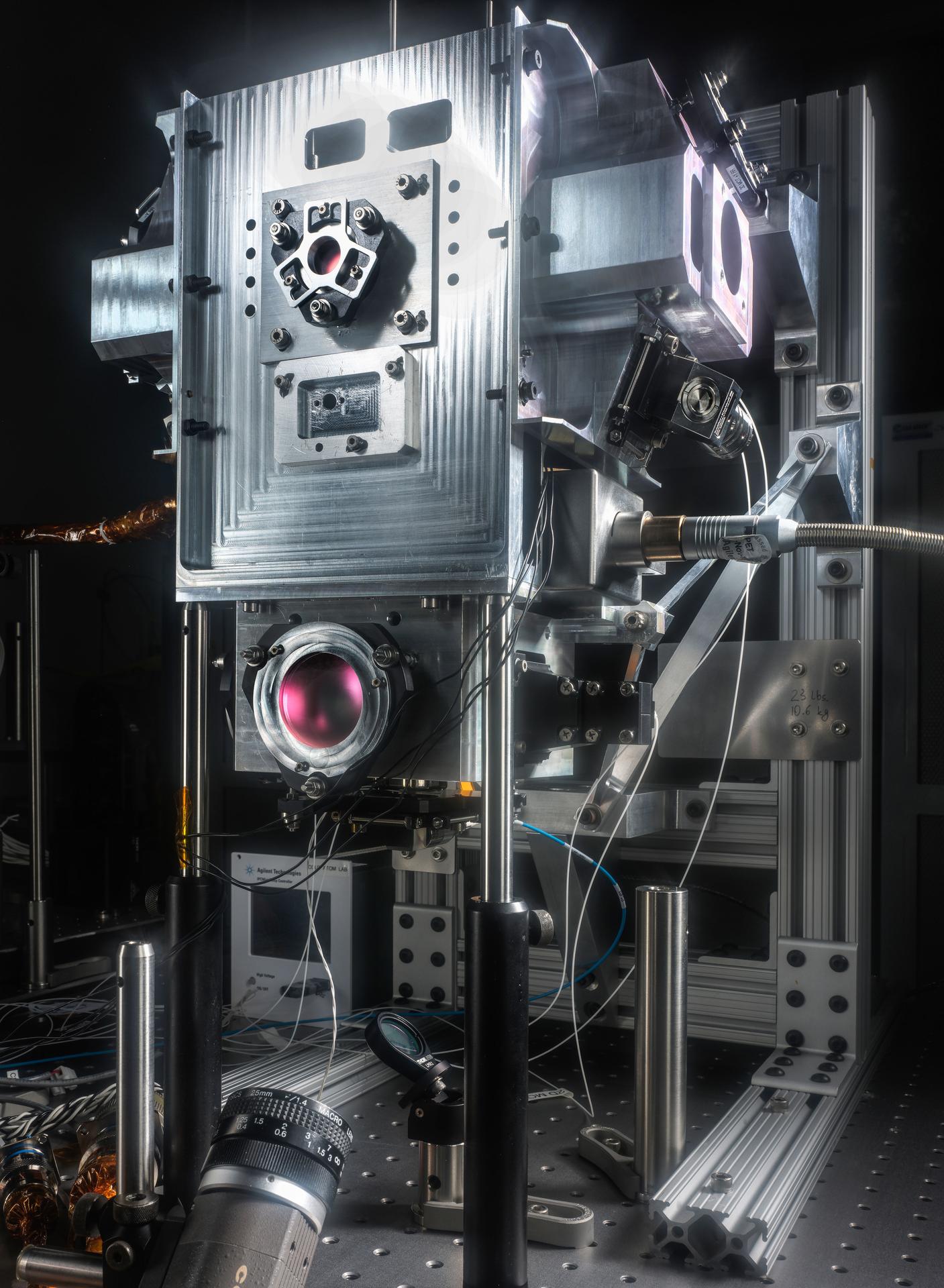
Optical prots ring the Electrostatic Levitator (ESL) vacuum chamber to admit light from the heating laser (the beam passes through the window at left), poisitioning lasers (one port is at center), and lamps (such as the deuterium arc lamp at right), and to allow diagnostic instruments to view the sample. The ESL uses static electricity to suspend an object (about 2-3 mm in diameter) inside a vacuum chamber while a laser heats the sample until it melts. This lets scientists record a wide range of physical properties without the sample contacting the container or any instruments, conditions that would alter the readings. The Electrostatic Levitator is one of several tools used in NASA's microgravity materials science program.
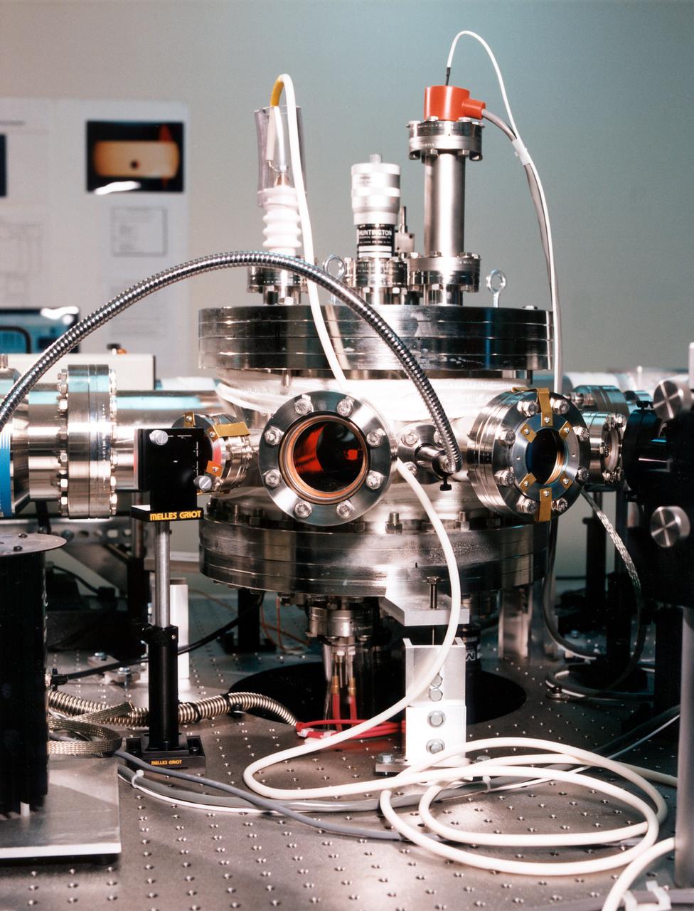
Optical prots ring the Electrostatic Levitator (ESL) vacuum chamber to admit light from the heating laser (the beam passes through the window at left), poisitioning lasers (one port is at center), and lamps (arc lamp at right), and to allow diagnostic instruments to view the sample. The ESL uses static electricity to suspend an object (about 2-3 mm in diameter) inside a vacuum chamber while a laser heats the sample until it melts. This lets scientists record a wide range of physical properties without the sample contacting the container or any instruments, conditions that would alter the readings. The Electrostatic Levitator is one of several tools used in NASA's microgravity materials science program.
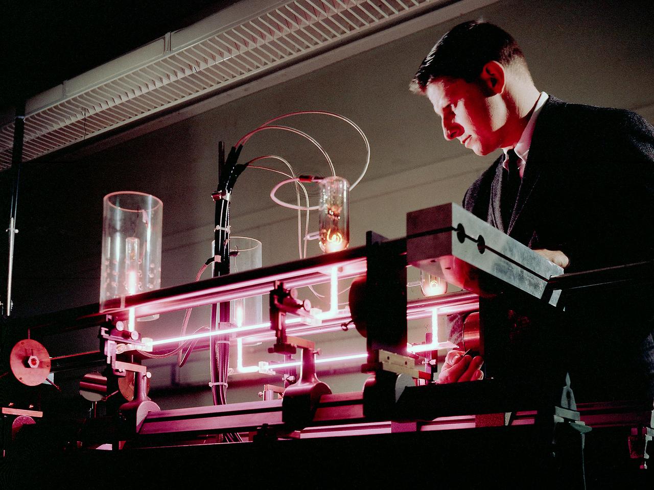
Richard Lancashire operates a gas laser interferometer in the Electric Conversion Laboratory at the National Aeronautics and Space Administration (NASA) Lewis Research Center. Lewis was in the midst of a long-term effort to develop methods of delivering electrical power to spacecraft using nuclear, solar, or electrochemical technologies. Lancashire was measuring the thermionic diode’s plasma particle density. The thermionic diodes were being studied for possible use in radioisotope thermoelectric generators for use in space. Microwave interferometry was one method of measuring transient plasmas. The interferometer measured the difference between the frequencies of two laser beams, one of which passed through the diode. The electron density was measured by revealing the phase shift of the transmitted microwave beam brought about by a change in the plasma refraction. Microwave interferometry, however, offers poor spatial resolution and has limited range of applicability.
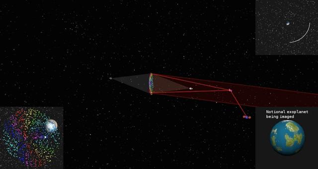
This simulated image shows how a cloud of glitter in geostationary orbit would be illuminated and controlled by two laser beams. As the cloud orbits Earth, grains scatter the sun's light at different angles like many tiny prisms, similar to how rainbows are produced from light being dispersed by water droplets. That is why the project concept is called "Orbiting Rainbows." The cloud functions like a reflective surface, allowing the exoplanet (displayed in the bottom right) to be imaged. The orbit path is shown in the top right. On the bottom left, Earth's image is seen behind the cloud. To image an exoplanet, the cloud would need to have a diameter of nearly 98 feet (30 meters). This simulation confines the cloud to a 3.3 x 3.3 x 3.3 foot volume (1 x 1 x 1 meter volume) to simplify the computations. The elements of the orbiting telescope are not to scale. Orbiting Rainbows is currently in Phase II development through the NASA Innovative Advanced Concepts (NIAC) Program. It was one of five technology proposals chosen for continued study in 2014. In the current phase, Orbiting Rainbows researchers are conducting small-scale ground experiments to demonstrate how granular materials can be manipulated using lasers and simulations of how the imaging system would behave in orbit. http://photojournal.jpl.nasa.gov/catalog/PIA19318
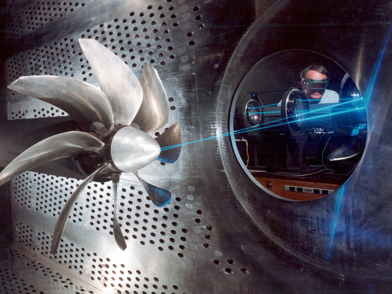
NASA Lewis Research Center researcher, John S. Sarafini, uses a laser doppler velocimeter to analyze a Hamilton Standard SR-2 turboprop design in the 8- by 6-Foot foot Supersonic Wind Tunnel. Lewis researchers were analyzing a series of eight-bladed propellers in their wind tunnels to determine their operating characteristics at speeds up to Mach 0.8. The program, which became the Advanced Turboprop (ATP), was part of a NASA-wide Aircraft Energy Efficiency Program undertaken to reduce aircraft fuel costs by 50 percent. The ATP concept was different from the turboprops in use in the 1950s. The modern versions had at least eight blades and were swept back for better performance. Bell Laboratories developed the laser doppler velocimeter technology in the 1960s to measure velocity of transparent fluid flows or vibration motion on reflective surfaces. Lewis researchers modified the device to measure the flow field of turboprop configurations in the transonic speed region. The modifications were necessary to overcome the turboprop’s vibration and noise levels. The laser beam was split into two beams which were crossed at a specific point. This permits researchers to measure two velocity components simultaneously. This data measures speeds both ahead and behind the propeller blades. Researchers could use this information as they sought to advance flow fields and to verify computer modeling codes.
This timelapse video shows the NASA Jet Propulsion Laboratory's Table Mountain Facility near Wrightwood, California, transmitting its 3-kilowatt laser beacon to the agency's Deep Space Optical Communications (DSOC) experiment aboard NASA's Psyche mission on June 2, 2025; the spacecraft was about 143 million miles (230 million kilometers) from Earth at the time. Managed by JPL, DSOC was designed to demonstrate that data encoded in laser photons could be reliably transmitted, received, and then decoded after traveling millions of miles from Earth out to Mars distances. Nearly two years after launching aboard the agency's Psyche mission in 2023, the demonstration completed its 65th and final "pass" on Sept. 2, 2025, sending a laser signal to Psyche and receiving the return signal from 218 million miles (350 million kilometers) away. Animation available at https://photojournal.jpl.nasa.gov/catalog/PIA26663
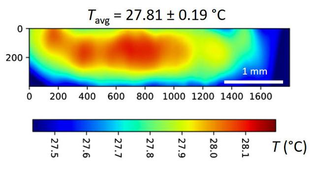
jsc2024e065172 (10/3/2024) --- A temperature map is seen within a microgel suspension illuminated by the Colloidal Solids (COLIS) near infrared laser (NIR). Reference ground tests for the Colloidal Solids (COLIS) investigation show spatial variation of the sample temperature while illuminating an aqueous, dense suspension of thermosensitive microgels with a 0.5 s pulse of NIR laser light. The NIR beam propagates from left to right. The sample temperature with no NIR laser is uniform and set to 27°C. The temperature values are inferred from the change in scattered intensity at a scattering angle of 90°, as recorded by one of the complementary metal-oxide-semiconductor (CMOS) cameras of COLIS. Results from this investigation are expected to provide a deeper understanding of soft solid interactions with gravity and microgravity, paving the way for the design of new materials. Image courtesy of Redwire Space Laboratories, Kruibeke – Belgium.
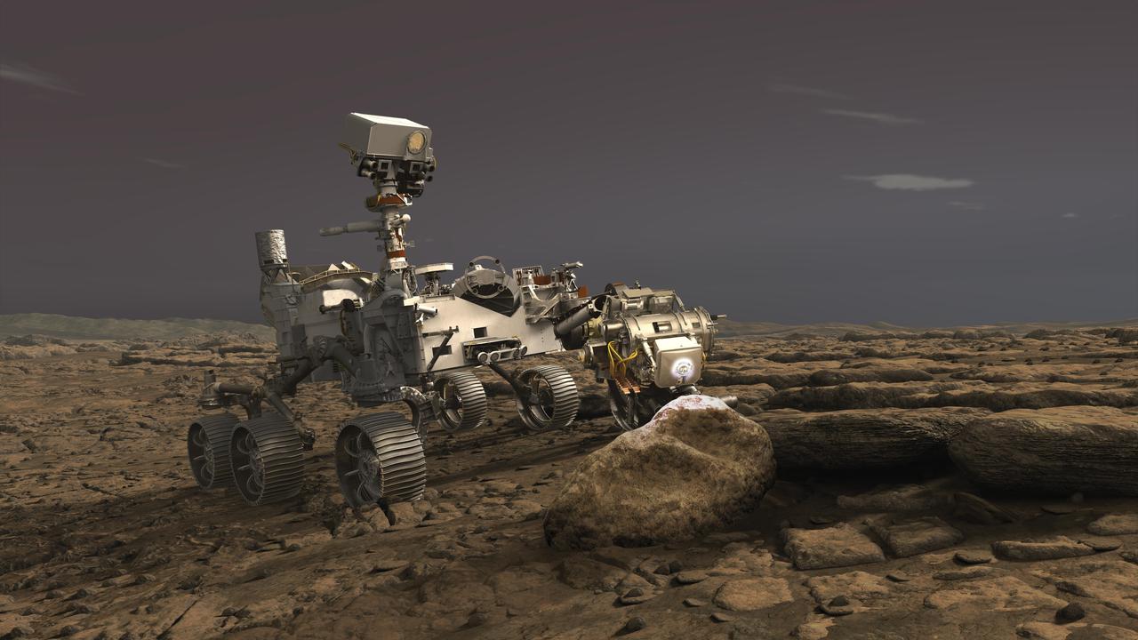
In this illustration, NASA's Perseverance rover uses its Planetary Instrument for X-ray Lithochemistry (PIXL) instrument to analyze a rock on the surface of Mars. PIXL uses a focused X-ray beam to analyze the chemistry of features as small as a grain of sand. The tiny but powerful beam causes rocks to fluoresce, or produce a glow. While the glow is invisible to the human eye, it is detectable by the instrument and varies according to the rock's elemental chemistry. PIXL scan the beam across the surface of the rock to produce a postage-stamp-sized map of the rock's chemistry at the end of an overnight scan. PIXL also has an optical fiducial system (OFS) that includes white "flood lights" — seen on the rock in this artist's concept — that is used together with a pattern of red lasers to illuminate the rock while its camera captures images of the mapped area. The pictures are used for multiple purposes: PIXL analyzes them on board to work out where the target is — in 3D — and move itself into the right position for science collection and the safety of the instrument. The pictures are also downlinked to Earth so scientists can see exactly where each measurement was taken. This allows scientists to tie chemistry accurately to rock texture, which helps them to determine how these features formed and whether they were biological in nature. https://photojournal.jpl.nasa.gov/catalog/PIA23719
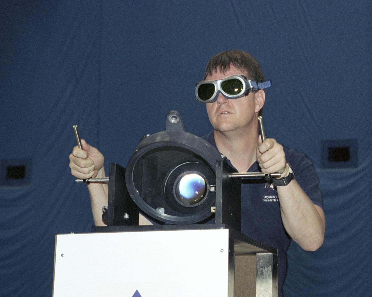
NASA Dryden project engineer Dave Bushman carefully aims the optics of a laser device at a solar cell panel on a model aircraft during the first flight demonstration of an aircraft powered by laser light.
jsc2026e014318 (March 23, 2026) --- Preflight image of the SM-3X module as part of the Cold Atom Lab (CAL). NASA’s CAL hosts multiple experiments that explore the fundamental nature of atoms by cooling them down to nearly absolute zero (the coldest temperature matter can reach). The pink-colored coated mirrors on the front and sides reflect five sets of laser beams to pre-cool atoms before they are loaded into a magnetic trap. Radio frequencies from an internal antenna lower the temperature of the trapped atoms to the extreme cold needed to observe quantum phenomena. Credit: NASA/JPL-Caltech.
National Aeronautics and Space Administration (NASA) Lewis Research Center researcher Americo Forestieri aims a ruby laser beam at a crystal to determine the effects of its radiation. Forestieri was a researcher in the Electric Component Experiment Section of the Space Power System Division. Lewis was in the midst of a long-term effort to develop methods of delivering electrical power to spacecraft using nuclear, solar, or electrochemical technologies. Ruby lasers contain a ruby crystal with mirrors on either side. The laser action is created when a high-intensity lamp shines around the ruby and excites the electrons in the ruby’s chromium atoms. After the excitation, the electrons emit their ruby-red light. The mirrors reflect some of this red light back and forth inside the ruby which causes other excited chromium atoms to produce additional red light. This continues until the light pulse reaches high power levels and consumes all of the energy stored in the crystal. Forestieri used optical absorption and electron paramagnetic resonance techniques to study the extent and manner in which the radiation interacted with the samples. He determined that individual bands were assigned to specific electronic transitions. He also studied the atomic changes in the ruby crystals after irradiation. He found that complex interactions depend on the crystal pretreatment, purity, and irradiation dose.
VANDENBERG AIR FORCE BASE, CALIF. - At Vandenberg Air Force Base in California, light beams are emitted during LIDAR (LIght Detection And Ranging) laser testing on the CALIPSO spacecraft. CALIPSO stands for Cloud-Aerosol LIDAR and Infrared Pathfinder Satellite Observation. LIDAR measures distance, speed, rotation, chemical composition and concentration. CALIPSO and CloudSat will fly in formation with three other satellites in the A-train constellation to enhance understanding of our climate system. They are highly complementary satellites and together they will provide never-before-seen 3-D perspectives of how clouds and aerosols form, evolve, and affect weather and climate. Launch of CALIPSO_CloudSat aboard a Boeing Delta II rocket is scheduled for 3:01 a.m. PDT Sept. 29.
VANDENBERG AIR FORCE BASE, CALIF. - At Vandenberg Air Force Base in California, a light beam is emitted during LIDAR (LIght Detection And Ranging) laser testing on the CALIPSO spacecraft. CALIPSO stands for Cloud-Aerosol LIDAR and Infrared Pathfinder Satellite Observation. LIDAR measures distance, speed, rotation, chemical composition and concentration. CALIPSO and CloudSat will fly in formation with three other satellites in the A-train constellation to enhance understanding of our climate system. They are highly complementary satellites and together they will provide never-before-seen 3-D perspectives of how clouds and aerosols form, evolve, and affect weather and climate. Launch of CALIPSO_CloudSat aboard a Boeing Delta II rocket is scheduled for 3:01 a.m. PDT Sept. 29.
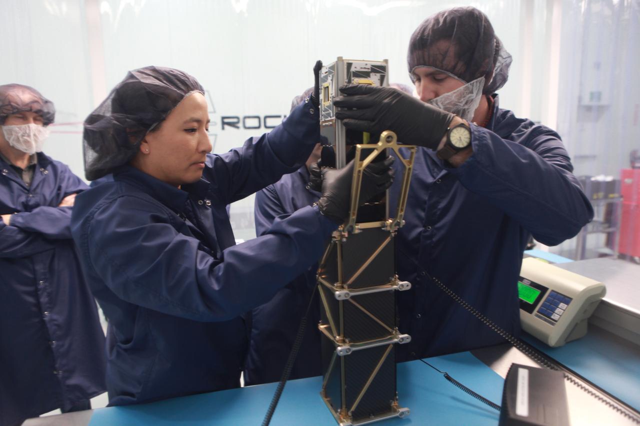
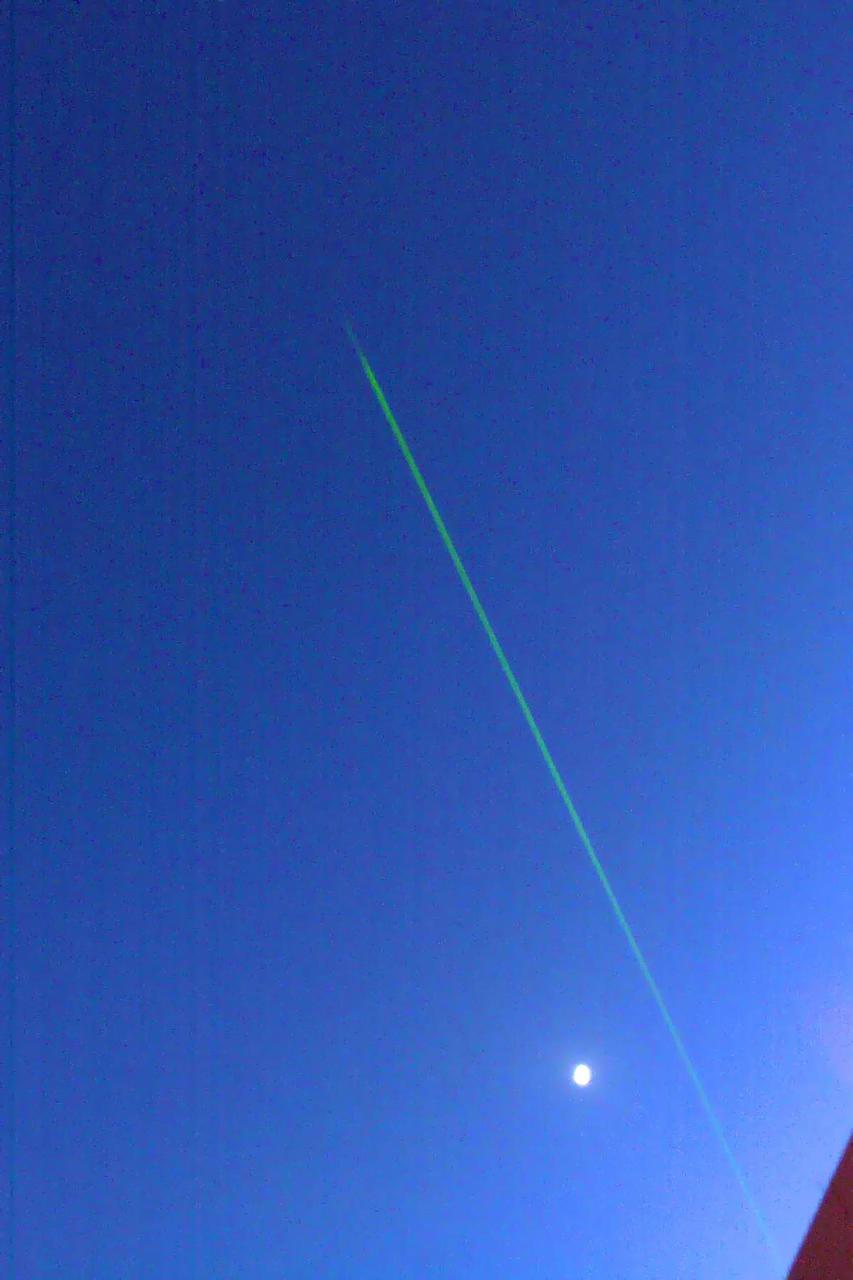
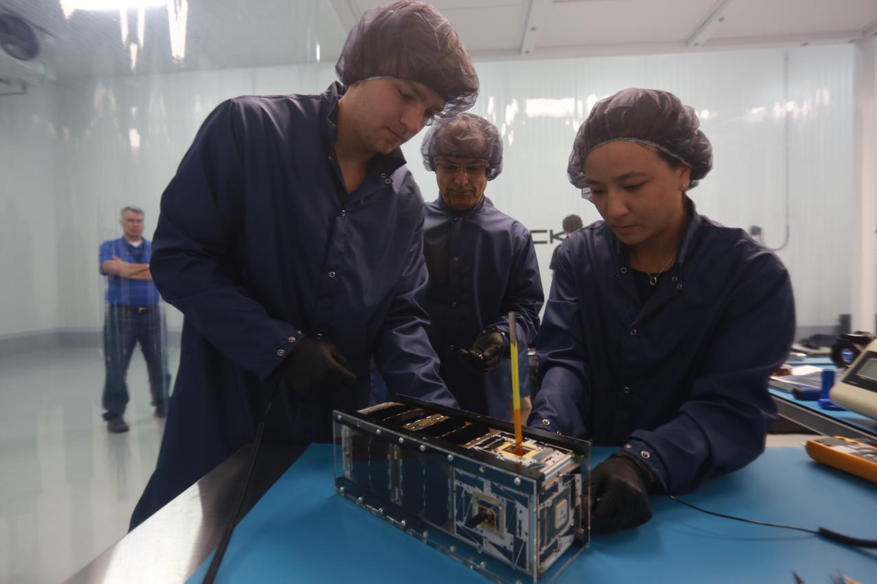
The goal of the CHOMPTT mission is to demonstrate new technologies that could be used for navigation and satellite networking in deep space. For future explorers and colonizers of the Moon or Mars, navigation systems like GPS here on Earth, will be essential. The key idea behind CHOMPTT is to use lasers to transfer time code data over long distances instead of radio waves. Because lasers can be more tightly beamed compared to radio waves, more of the transmitted energy reaches its intended target, making them more power-efficient. CHOMPTT takes advantage of this and of new miniature but very stable atomic clocks to produce a timing system with performance similar to that of GPS, but in a very compact and power efficient form factor. We will use a pulsed laser system, located at the Kennedy Space Center that will be synchronized with an atomic clock. Laser pulses will propagate from the ground to the orbiting CHOMPTT CubeSat and back. By precisely measuring the time of emission and detection of these pulses on the ground and in space we can calculate the time discrepancy between the ground atomic clock and the atomic clock on CHOMPTT. Our goal is to do this with an accuracy of 0.2 billionths of a second, or the time it takes light to travel just 6 centimeters. In the future, we envision using this technology on constellations or swarms of small satellites, for example orbiting the Moon, to equip them with precision navigation, networking, and ranging capabilities. CHOMPTT is a collaboration between the University of Florida and the NASA Ames Research Center. The CHOMPTT precision timing payload was designed and built by the Precision Space Systems Lab at the University of Florida, while the 3U CubeSat bus that has prior flight heritage, was provided by NASA Ames. The CHOMPTT mission has been funded by the Air Force Research Lab and by NASA.
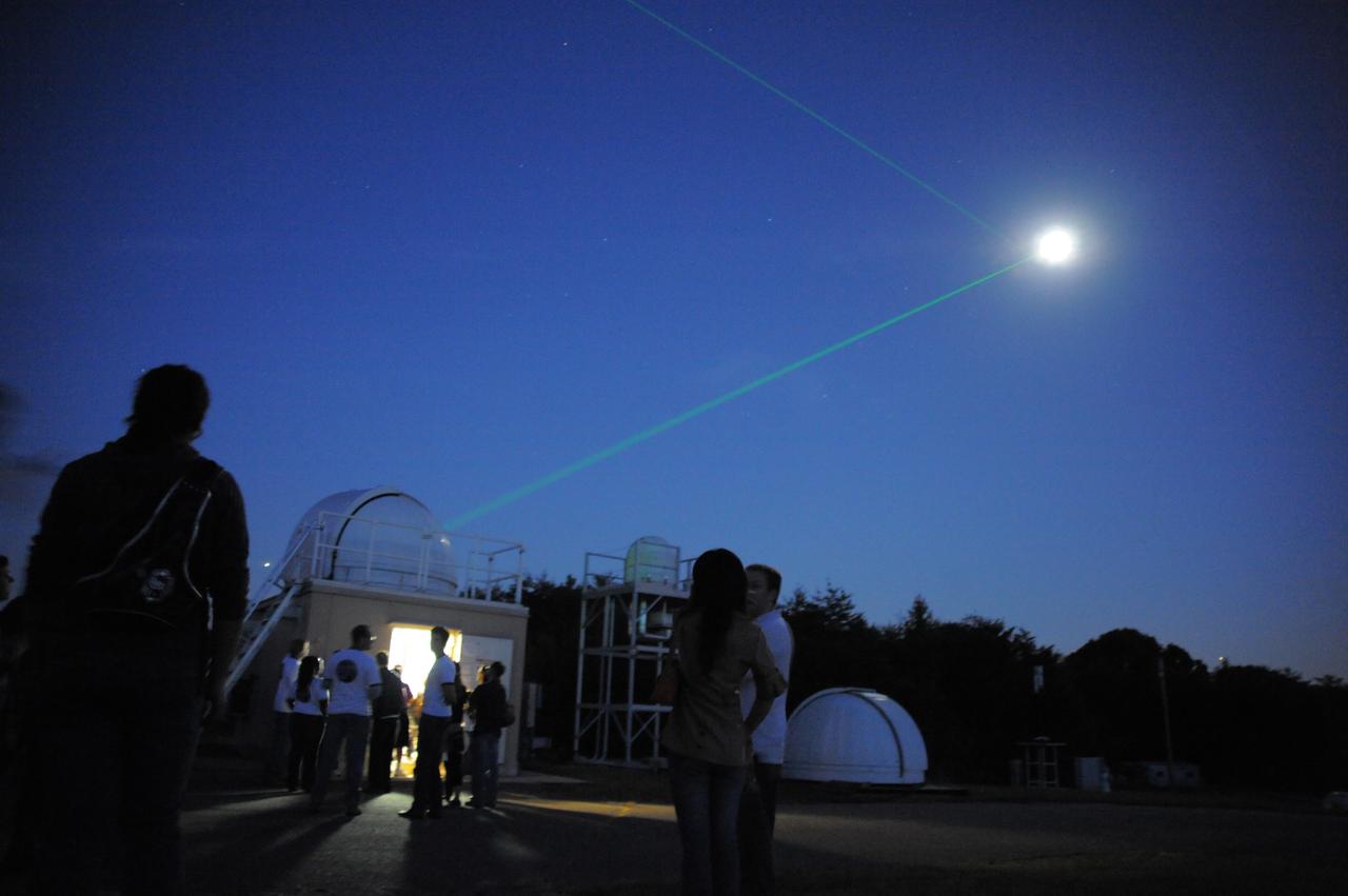
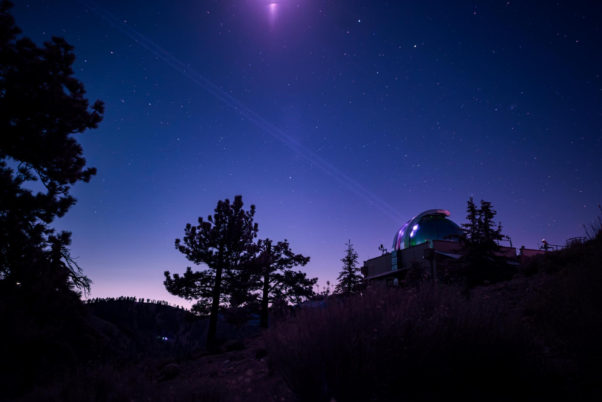
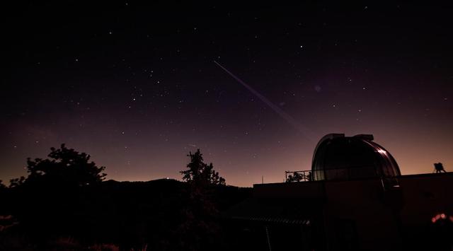
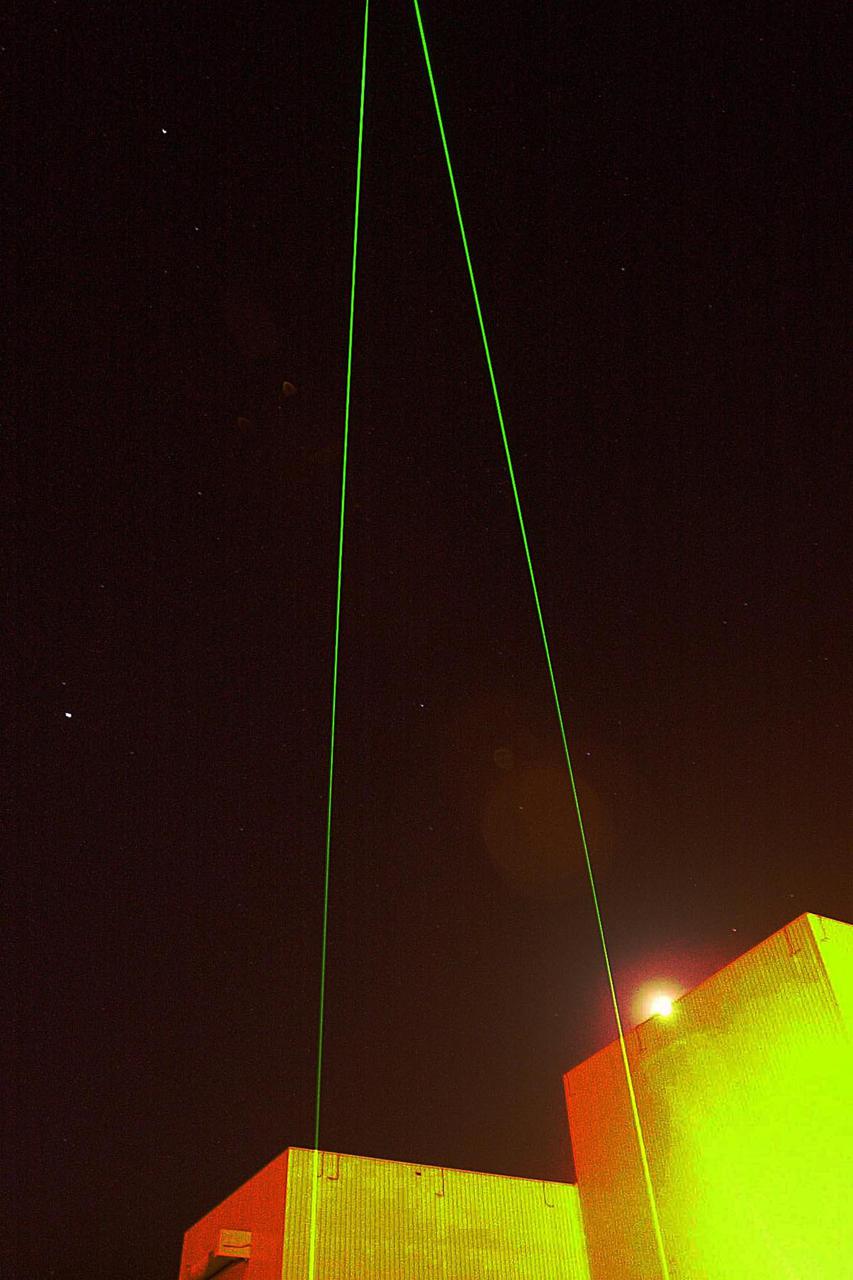
Visitors get a rare opportunity to view laser beams pointed at the moon at Optical Site. Goddard's Laser Ranging Facility directs a laser toward the Lunar Reconassaince Orbiter on International Observe the Moon Night. (Sept 18, 2010) Background on laser ranging: <a href="http://www.nasa.gov/mission_pages/LRO/news/LRO_lr.html" rel="nofollow">www.nasa.gov/mission_pages/LRO/news/LRO_lr.html</a> Credit: NASA/GSFC/Debbie Mccallum On September 18, 2010 the world joined the NASA Goddard Space Flight Center's Visitor Center in Greenbelt, Md., as well as other NASA Centers to celebrate the first annual International Observe the Moon Night (InOMN). To read more go to: <a href="http://www.nasa.gov/centers/goddard/news/features/2010/moon-night.html" rel="nofollow">www.nasa.gov/centers/goddard/news/features/2010/moon-nigh...</a> <b><a href="http://www.nasa.gov/centers/goddard/home/index.html" rel="nofollow">NASA Goddard Space Flight Center</a></b> contributes to NASA’s mission through four scientific endeavors: Earth Science, Heliophysics, Solar System Exploration, and Astrophysics. Goddard plays a leading role in NASA’s endeavors by providing compelling scientific knowledge to advance the Agency’s mission. <b>Follow us on <a href="http://twitter.com/NASA_GoddardPix" rel="nofollow">Twitter</a></b> <b>Join us on <a href="http://www.facebook.com/pages/Greenbelt-MD/NASA-Goddard/395013845897?ref=tsd" rel="nofollow">Facebook</a></b>
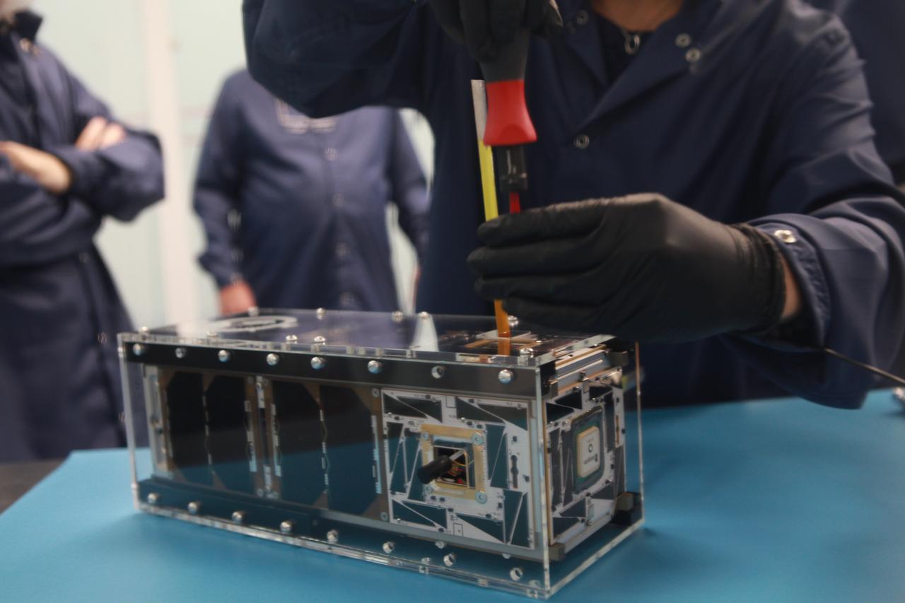
The goal of the CHOMPTT mission is to demonstrate new technologies that could be used for navigation and satellite networking in deep space. For future explorers and colonizers of the Moon or Mars, navigation systems like GPS here on Earth, will be essential. The key idea behind CHOMPTT is to use lasers to transfer time code data over long distances instead of radio waves. Because lasers can be more tightly beamed compared to radio waves, more of the transmitted energy reaches its intended target, making them more power-efficient. CHOMPTT takes advantage of this and of new miniature but very stable atomic clocks to produce a timing system with performance similar to that of GPS, but in a very compact and power efficient form factor. We will use a pulsed laser system, located at the Kennedy Space Center that will be synchronized with an atomic clock. Laser pulses will propagate from the ground to the orbiting CHOMPTT CubeSat and back. By precisely measuring the time of emission and detection of these pulses on the ground and in space we can calculate the time discrepancy between the ground atomic clock and the atomic clock on CHOMPTT. Our goal is to do this with an accuracy of 0.2 billionths of a second, or the time it takes light to travel just 6 centimeters. In the future, we envision using this technology on constellations or swarms of small satellites, for example orbiting the Moon, to equip them with precision navigation, networking, and ranging capabilities. CHOMPTT is a collaboration between the University of Florida and the NASA Ames Research Center. The CHOMPTT precision timing payload was designed and built by the Precision Space Systems Lab at the University of Florida, while the 3U CubeSat bus that has prior flight heritage, was provided by NASA Ames. The CHOMPTT mission has been funded by the Air Force Research Lab and by NASA.
The goal of the CHOMPTT mission is to demonstrate new technologies that could be used for navigation and satellite networking in deep space. For future explorers and colonizers of the Moon or Mars, navigation systems like GPS here on Earth, will be essential. The key idea behind CHOMPTT is to use lasers to transfer time code data over long distances instead of radio waves. Because lasers can be more tightly beamed compared to radio waves, more of the transmitted energy reaches its intended target, making them more power-efficient. CHOMPTT takes advantage of this and of new miniature but very stable atomic clocks to produce a timing system with performance similar to that of GPS, but in a very compact and power efficient form factor. We will use a pulsed laser system, located at the Kennedy Space Center that will be synchronized with an atomic clock. Laser pulses will propagate from the ground to the orbiting CHOMPTT CubeSat and back. By precisely measuring the time of emission and detection of these pulses on the ground and in space we can calculate the time discrepancy between the ground atomic clock and the atomic clock on CHOMPTT. Our goal is to do this with an accuracy of 0.2 billionths of a second, or the time it takes light to travel just 6 centimeters. In the future, we envision using this technology on constellations or swarms of small satellites, for example orbiting the Moon, to equip them with precision navigation, networking, and ranging capabilities. CHOMPTT is a collaboration between the University of Florida and the NASA Ames Research Center. The CHOMPTT precision timing payload was designed and built by the Precision Space Systems Lab at the University of Florida, while the 3U CubeSat bus that has prior flight heritage, was provided by NASA Ames. The CHOMPTT mission has been funded by the Air Force Research Lab and by NASA.

Two beams flash across a starry sky toward the Moon at Optical Site. Goddard's Laser Ranging Facility directs a laser toward the Lunar Reconassaince Orbiter on International Observe the Moon Night. (Sept 18, 2010) Background on laser ranging: <a href="http://www.nasa.gov/mission_pages/LRO/news/LRO_lr.html" rel="nofollow">www.nasa.gov/mission_pages/LRO/news/LRO_lr.html</a> Credit: NASA/GSFC/Debbie Mccallum On September 18, 2010 the world joined the NASA Goddard Space Flight Center's Visitor Center in Greenbelt, Md., as well as other NASA Centers to celebrate the first annual International Observe the Moon Night (InOMN). To read more go to: <a href="http://www.nasa.gov/centers/goddard/news/features/2010/moon-night.html" rel="nofollow">www.nasa.gov/centers/goddard/news/features/2010/moon-nigh...</a> <b><a href="http://www.nasa.gov/centers/goddard/home/index.html" rel="nofollow">NASA Goddard Space Flight Center</a></b> contributes to NASA’s mission through four scientific endeavors: Earth Science, Heliophysics, Solar System Exploration, and Astrophysics. Goddard plays a leading role in NASA’s endeavors by providing compelling scientific knowledge to advance the Agency’s mission. <b>Follow us on <a href="http://twitter.com/NASA_GoddardPix" rel="nofollow">Twitter</a></b> <b>Join us on <a href="http://www.facebook.com/pages/Greenbelt-MD/NASA-Goddard/395013845897?ref=tsd" rel="nofollow">Facebook</a></b>
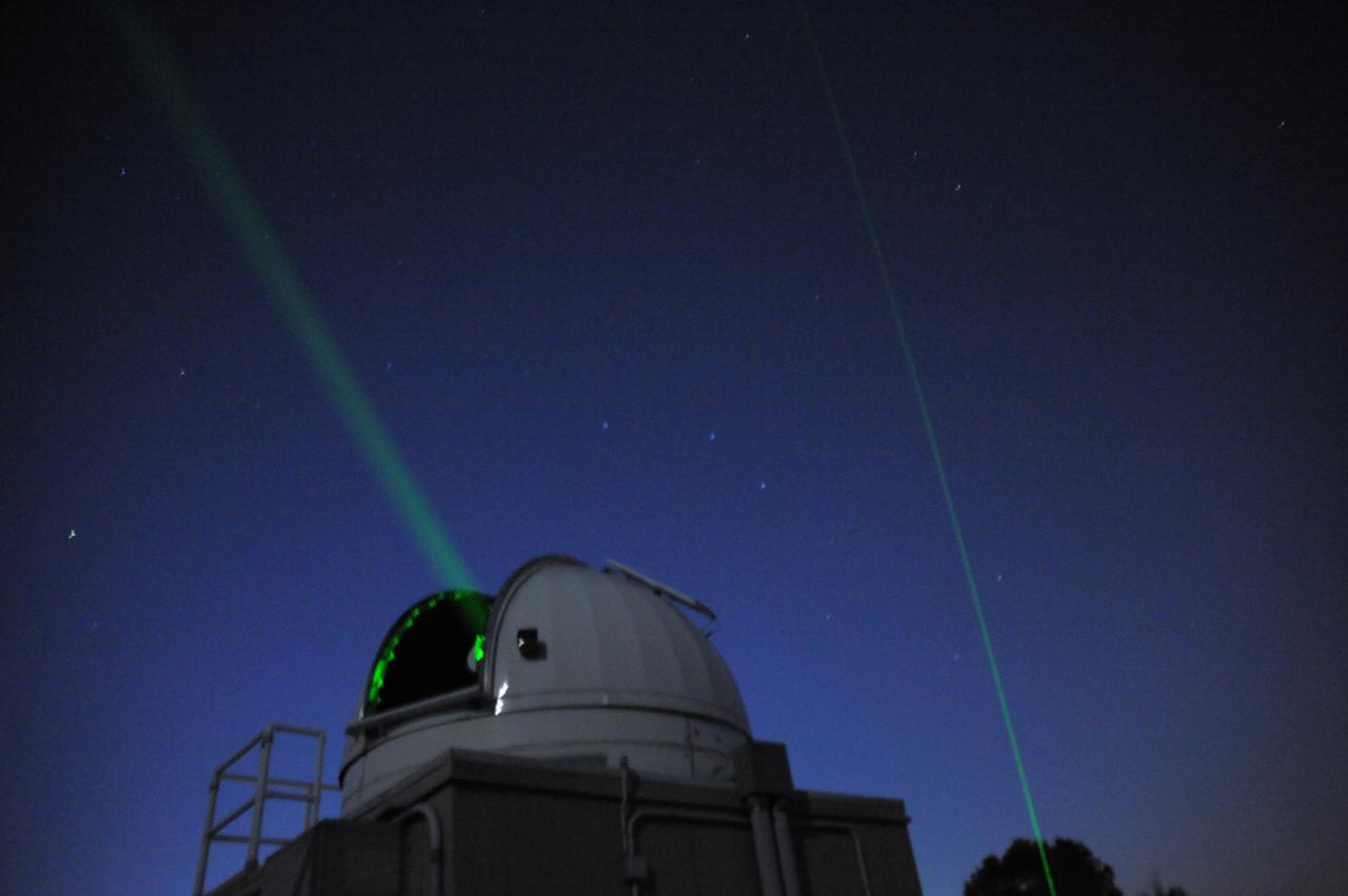
Double beams shoot into the night sky during the Internation Observe the Moon night event. Goddard's Laser Ranging Facility directs a laser toward the Lunar Reconassaince Orbiter on International Observe the Moon Night. (Sept 18, 2010) Background on laser ranging: <a href="http://www.nasa.gov/mission_pages/LRO/news/LRO_lr.html" rel="nofollow">www.nasa.gov/mission_pages/LRO/news/LRO_lr.html</a> Credit: NASA/GSFC/Debbie Mccallum On September 18, 2010 the world joined the NASA Goddard Space Flight Center's Visitor Center in Greenbelt, Md., as well as other NASA Centers to celebrate the first annual International Observe the Moon Night (InOMN). To read more go to: <a href="http://www.nasa.gov/centers/goddard/news/features/2010/moon-night.html" rel="nofollow">www.nasa.gov/centers/goddard/news/features/2010/moon-nigh...</a> <b><a href="http://www.nasa.gov/centers/goddard/home/index.html" rel="nofollow">NASA Goddard Space Flight Center</a></b> contributes to NASA’s mission through four scientific endeavors: Earth Science, Heliophysics, Solar System Exploration, and Astrophysics. Goddard plays a leading role in NASA’s endeavors by providing compelling scientific knowledge to advance the Agency’s mission. <b>Follow us on <a href="http://twitter.com/NASA_GoddardPix" rel="nofollow">Twitter</a></b> <b>Join us on <a href="http://www.facebook.com/pages/Greenbelt-MD/NASA-Goddard/395013845897?ref=tsd" rel="nofollow">Facebook</a></b>
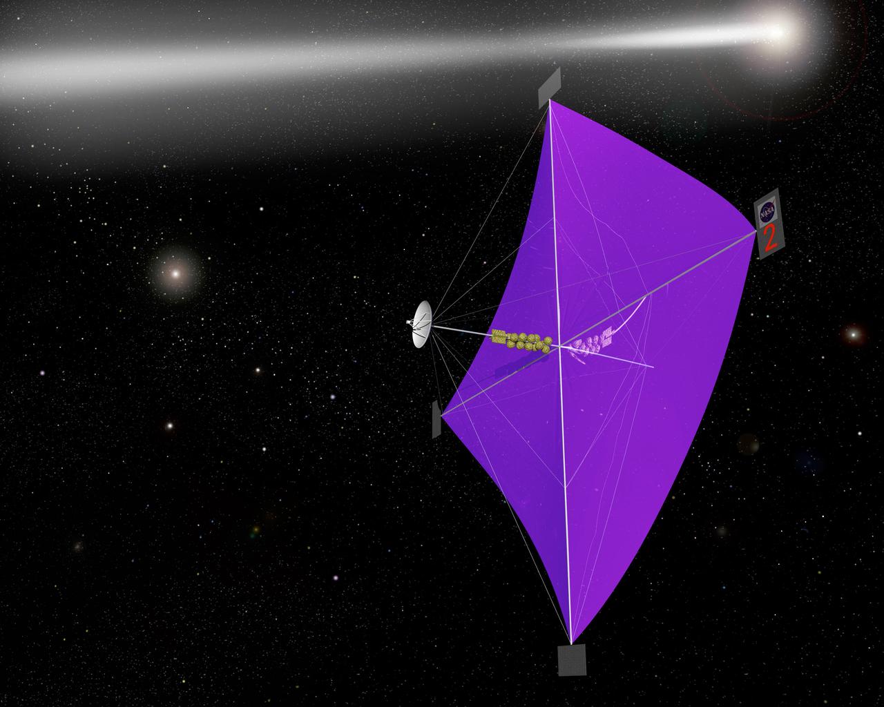
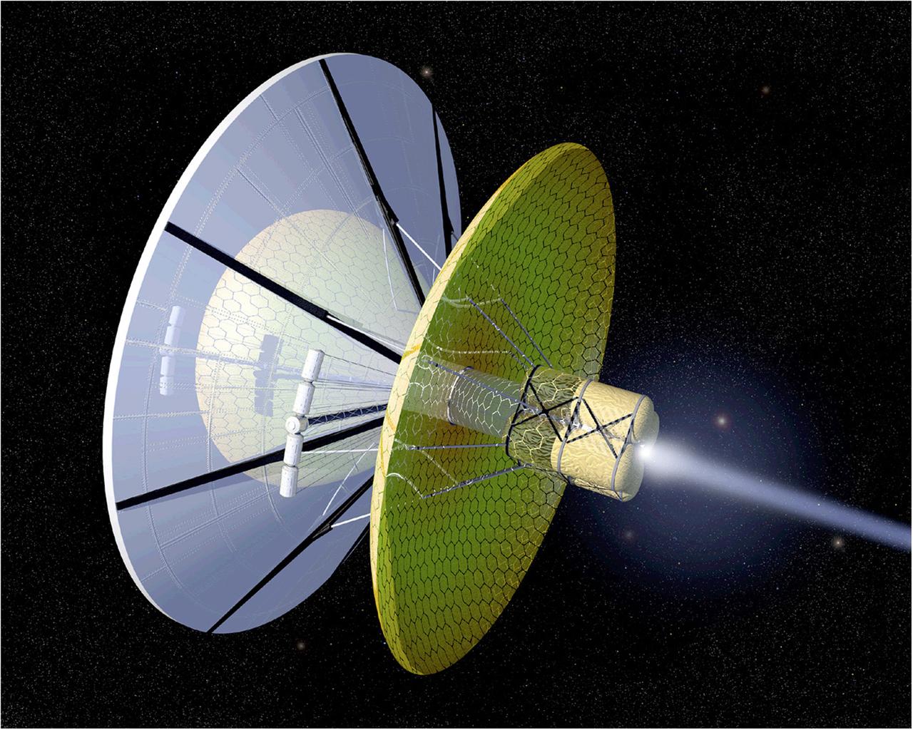
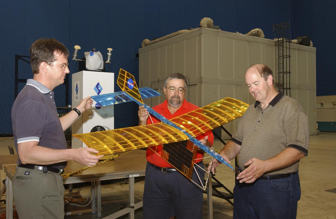
Engineers at Marshall Space Flight Center's Interstellar Propulsion Research department are proposing different solutions to combustion propellants for future space travel. Pictured here is one alternative, the solar sail, depicted through an artist's concept. The idea is, once deployed, the sail will allow solar winds to propel a spacecraft away from Earth and towards its destination. This would allow a spacecraft to travel indefinitely without the need to refuel during its prolong journey. Thin reflective sails could be propelled through space by sunlight, microwave beams, or laser beams, just as the wind pushes sailboats on Earth. The sail will be the largest spacecraft ever built, sparning 440 yards, twice the diameter of the Louisiana Super Dome. Construction materials are being tested in a simulated space environment, where they are exposed to harsh conditions to test their performance and durability in extremely hot and cold temperatures. A leading candidate for the construction material is a carbon fiber material whose density is less than 1/10 ounce per square yard, the equivalent of flattening one raisin to the point that it covers a square yard. In space, the material would unfurl like a fan when it is deployed from an expendable rocket. Mankind's first venture outside of our solar system is proposed for launch in a 2010 timeframe. An interstellar probe, powered by the fastest spacecraft ever flown, will zoom toward the stars at 58 miles per second. It will cover the distance from New York to Los Angeles in less than a minute and will travel over 23 billion miles beyond the edge of the solar system.
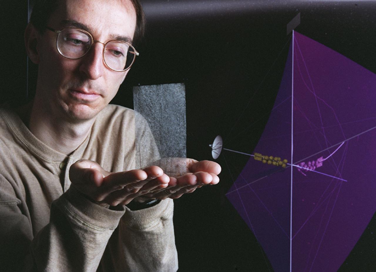
Engineers at Marshall Space Flight Center's (MSFC) Interstellar Propulsion Research department are proposing different solutions to combustion propellants for future space travel. One alternative being tested is the solar sail. The idea is, once deployed, the sail will allow solar winds to propel a spacecraft away from Earth and towards its destination. This would allow a spacecraft to travel indefinitely without the need to refuel during its ong journey. Thin reflective sails could be propelled through space by sunlight, microwave beams, or laser beams, just as the wind pushes sailboats on Earth. The sail will be the largest spacecraft ever built, sparning 440 yards, twice the diameter of the Louisiana Super Dome. Construction materials are being tested in a simulated space environment, where they are exposed to harsh conditions to test their performance and durability in extremely hot and cold temperatures. A leading candidate for the construction material is a carbon fiber material whose density is less than 1/10 ounce per square yard, the equivalent of flattening one raisin to the point that it covers a square yard. In space, the material would unfurl like a fan when it is deployed from an expendable rocket. This photo shows Les Johnson, manager of MSFC's Interstellar Propulsion Research Center holding the rigid, lightweight carbon fiber. An artist's concept of the sail is on the right. Mankind's first venture outside of our solar system is proposed for launch in a 2010 timeframe. An interstellar probe, powered by the fastest spacecraft ever flown, will zoom toward the stars at 58 miles per second. It will cover the distance from New York to Los Angeles in less than a minute and will travel over 23 billion miles beyond the edge of the solar system.

The Space Shuttle Discovery, mated to NASA's 747 Shuttle Carrier Aircraft (SCA), takes to the air for its ferry flight back to the Kennedy Space Center in Florida. The spacecraft, with a crew of six, was launched into a 57-degree high inclination orbit from the Kennedy Space Center, Florida, at 3:23 p.m., 9 September 1994. The mission featured the study of clouds and the atmosphere with a laser beaming system called Lidar In-Space Technology Experiment (LITE), and the first untethered space walk in ten years. A Spartan satellite was also deployed and later retrieved in the study of the sun's corona and solar wind. The mission was scheduled to end Sunday, 18 September, but was extended one day to continue science work. Bad weather at the Kennedy Space Center on 19 September, forced a one-day delay to September 20, with a weather divert that day to Edwards. Mission commander was Richard Richards, the pilot Blaine Hammond, while mission specialists were Jerry Linenger, Susan Helms, Carl Meade, and Mark Lee.

This artist's concept depicts a magnetar – a type of neutron star with a strong magnetic field – losing material into space in an ejection that would have caused the object's rotation to slow. Shown as thin green lines, the magnetic field lines influence the movement of charged material around the magnetar. In October 2022, astronomers using NASA's NICER (Neutron Star Interior Composition Explorer) on the International Space Station and NuSTAR (Nuclear Spectroscopic Telescope Array) in low Earth orbit observed a rapid slowdown in a nearby magnetar called SGR 1935+2154. They believe the slowdown was caused by a rapid loss of material. The slowdown coincided with the release a fast radio burst – an eruption of radio waves that last only for a fraction of a second but can release about as much energy as the Sun does in a year. The light also forms a laser-like beam, setting them apart from more chaotic cosmic explosions. The telescopes were able to observe SGR 1935+2154 for hours, catching a glimpse of what happened on its surface and in its immediate surroundings both before and after the fast radio burst. https://photojournal.jpl.nasa.gov/catalog/PIA26274
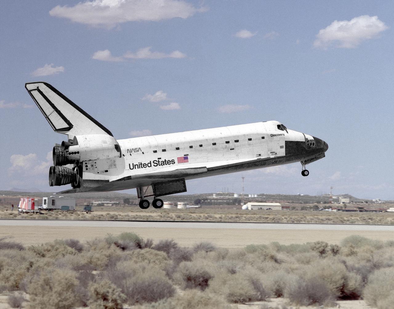
The Space Shuttle Discovery settles to the main runway at Edwards, California, at 2:13 p.m. (PDT) 20 September 1994, to conclude mission STS-64. The spacecraft, with a crew of six, was launched into a 57-degree high inclination orbit from the Kennedy Space Center, Florida, at 3:23 p.m. (PDT), 9 September 1994. The mission featured the study of clouds and the atmosphere with a laser beaming system called Lidar In-Space Technology Experiment (LITE), and the first untethered space walk in over ten years. A Spartan satellite was also deployed and later retrieved in the study of the sun's corona and the solar wind. The mission was scheduled to end Sunday, 18 September, but was extended one day to continue science work. Bad weather at the Kennedy Space Center on September 19, forced a one-day delay to September 20, with a weather divert that day to Edwards. Mission commander was Richard Richards, the pilot Blaine Hammond, while mission specialists were Jerry Linenger, Susan Helms, Carl Meade, and Mark Lee.

This image depicts the formation of multiple whirlpools in a sodium gas cloud. Scientists who cooled the cloud and made it spin created the whirlpools in a Massachusetts Institute of Technology laboratory, as part of NASA-funded research. This process is similar to a phenomenon called starquakes that appear as glitches in the rotation of pulsars in space. MIT's Wolgang Ketterle and his colleagues, who conducted the research under a grant from the Biological and Physical Research Program through NASA's Jet Propulsion Laboratory, Pasadena, Calif., cooled the sodium gas to less than one millionth of a degree above absolute zero (-273 Celsius or -460 Fahrenheit). At such extreme cold, the gas cloud converts to a peculiar form of matter called Bose-Einstein condensate, as predicted by Albert Einstein and Satyendra Bose of India in 1927. No physical container can hold such ultra-cold matter, so Ketterle's team used magnets to keep the cloud in place. They then used a laser beam to make the gas cloud spin, a process Ketterle compares to stroking a ping-pong ball with a feather until it starts spirning. The spinning sodium gas cloud, whose volume was one- millionth of a cubic centimeter, much smaller than a raindrop, developed a regular pattern of more than 100 whirlpools.
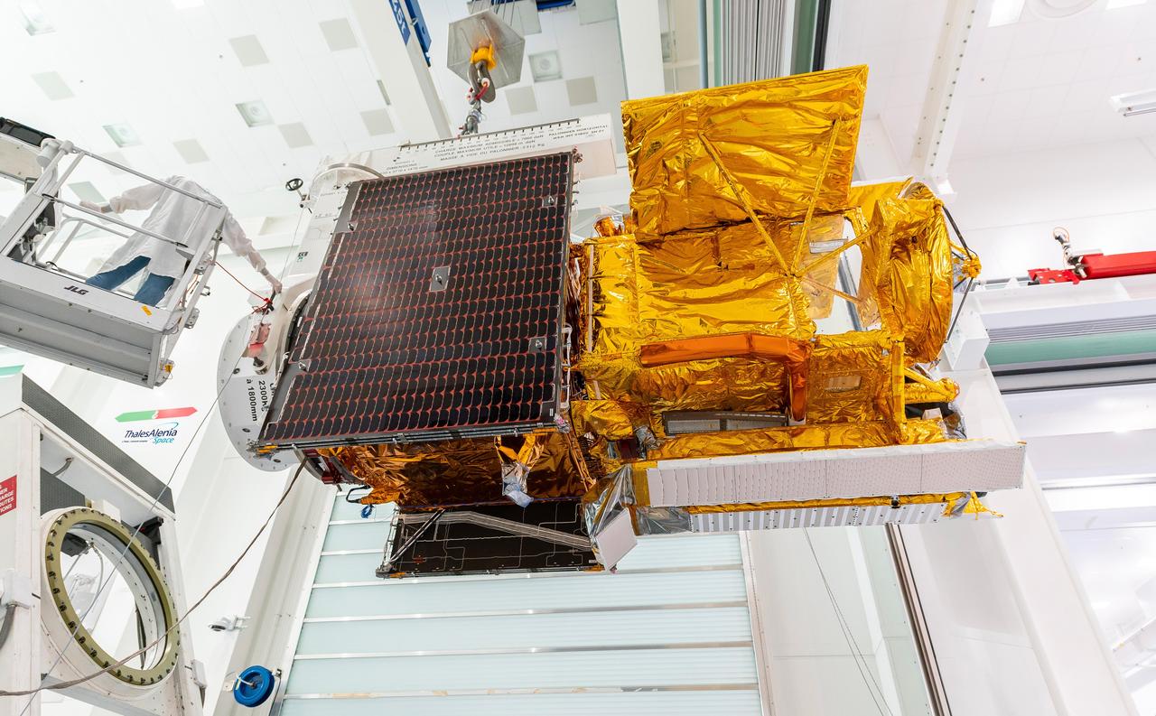
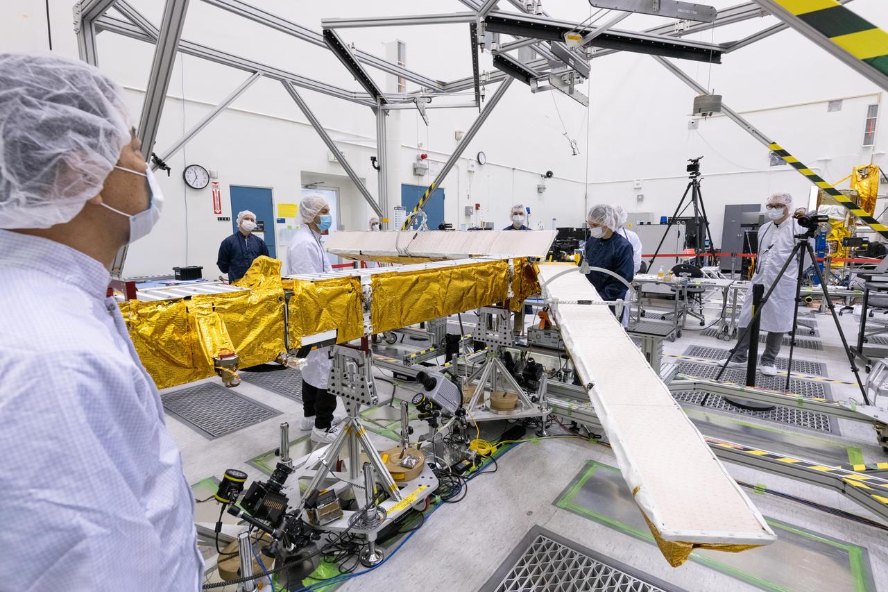
Workers in a clean room in Cannes, France, load the Surface Water and Ocean Topography (SWOT) satellite into a container in preparation for shipping the spacecraft to the U.S. SWOT is an international mission led by NASA and the French space agency Centre National d'Études Spatiales (CNES) that will survey water on more than 90% of Earth's surface. The spacecraft will view water in Earth's lakes, rivers, reservoirs, and the ocean in higher definition than ever before. The information that SWOT gathers will help inform water management decisions and prepare communities for rising seas and changing coastlines. It will also help researchers better understand the exchange of heat and carbon between the ocean and atmosphere, an important component of the role that Earth's ocean plays in the planet's climate. SWOT will launch out of the Vandenberg Space Force Base in central California no earlier than Dec. 5, 2022. SWOT is being jointly developed by NASA and CNES, with contributions from the Canadian Space Agency and the United Kingdom Space Agency. JPL, which is managed for NASA by Caltech in Pasadena, California, leads the U.S. component of the project. For the flight system payload, NASA is providing the KaRIn instrument, a GPS science receiver, a laser retroreflector, a two-beam microwave radiometer, and NASA instrument operations. CNES is providing the Doppler Orbitography and Radioposition Integrated by Satellite (DORIS) system, the dual frequency Poseidon altimeter (developed by Thales Alenia Space), the KaRIn radio-frequency subsystem (together with Thales Alenia Space and with support from the UK Space Agency), the platform, and ground control segment. CSA is providing the KaRIn high-power transmitter assembly. NASA is providing the launch vehicle and associated launch services. https://photojournal.jpl.nasa.gov/catalog/PIA24910
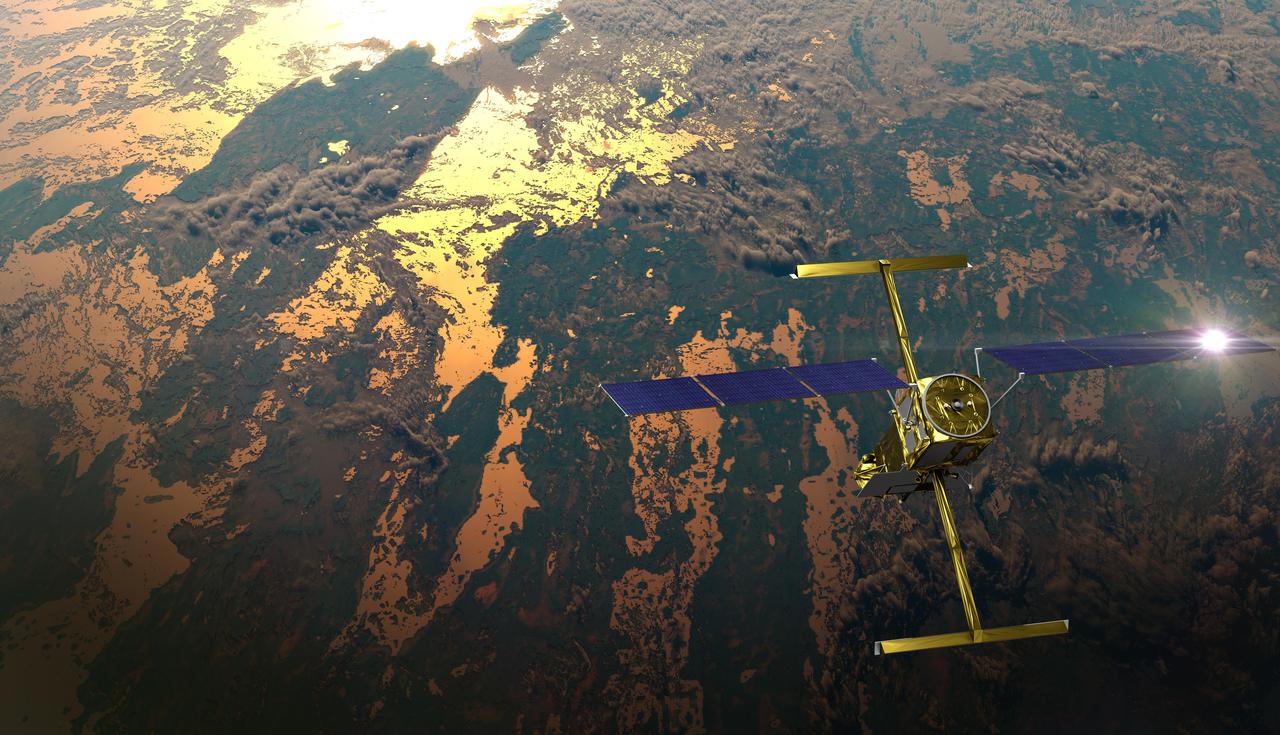
The international Surface Water and Ocean Topography (SWOT) satellite is shown in orbit over Earth in this illustration, with sunlight glinting off one of its solar arrays and both antennas of its Ka-band Radar Interferometer (KaRIn) instrument extended. The mission is a collaborative effort between NASA and the French space agency Centre National d'Études Spatiales (CNES) – with contributions from the Canadian Space Agency (CSA) and the UK Space Agency. KaRIn is the scientific heart of the SWOT satellite, which will survey the water on more than 90% of Earth's surface, measuring the height of water in lakes, rivers, reservoirs, and the ocean. To do that, KaRIn will transmit radar pulses to Earth's surface and use its two antennas to triangulate the return signals that bounce back. Mounted at the ends of a boom 33 feet (10 meters) long, the antennas will collect data along a swath 30 miles (50 kilometers) wide on either side of the satellite. KaRIn will operate in two modes: A lower-resolution mode over the ocean will involve significant onboard processing of the data to reduce the volume of information sent during downlinks to Earth; a higher-resolution mode will be used mainly over land. Scheduled to launch from Vandenberg Space Force Base in Central California on Dec. 15, 2022, SWOT is being jointly developed by NASA and CNES, with contributions from the CSA and the UK Space Agency. NASA's Jet Propulsion Laboratory, which is managed for the agency by Caltech in Pasadena, California, leads the U.S. component of the project. For the flight system payload, NASA is providing the Ka-band Radar Interferometer (KaRIn) instrument, a GPS science receiver, a laser retroreflector, a two-beam microwave radiometer, and NASA instrument operations. CNES is providing the Doppler Orbitography and Radioposition Integrated by Satellite (DORIS) system, the dual frequency Poseidon altimeter (developed by Thales Alenia Space), the KaRIn radio-frequency subsystem (together with Thales Alenia Space and with support from the UK Space Agency), the satellite platform, and ground control segment. CSA is providing the KaRIn high-power transmitter assembly. NASA is providing the launch vehicle and associated launch services. https://photojournal.jpl.nasa.gov/catalog/PIA25595
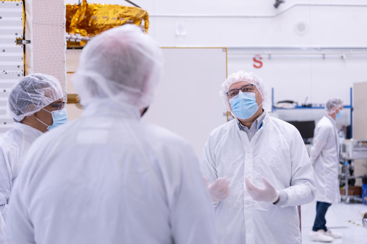
The new international satellite mission called Surface Water and Ocean Topography (SWOT) — slated for launch in late 2022 — will measure the height of Earth's surface water. The data the spacecraft will collect will help researchers understand and track the volume and location of water around the world. The satellite will assist with monitoring changes in floodplains and wetlands, measuring how much fresh water flows into and out of lakes and rivers and back to the ocean, and tracking regional shifts in sea level at scales never seen before. The satellite will also provide information on small-scale ocean currents that will support real-time marine operations affected by tides, currents, storm surge, sediment transport, and water quality issues. The payload is taking shape in a clean room at NASA's Jet Propulsion Laboratory in Southern California before being shipped to France. There, technicians and engineers from the French space agency Centre National d'Etudes Spatial (CNES), their prime contractor Thales Alenia Space, and JPL will complete the build and prepare the satellite for shipment to its California launch site at Vandenberg Air Force Base. JPL project manager Parag Vaze (pronounced vah-zay) is central to ensuring the handoff to his CNES counterpart Thierry Lafon goes smoothly. SWOT is being jointly developed by NASA and CNES, with contributions from the Canadian Space Agency (CSA) and United Kingdom Space Agency (UKSA). JPL, which is managed for NASA by Caltech in Pasadena, California, leads the U.S. component of the project. For the flight system, NASA is providing the Ka-band Radar Interferometer (KaRIn) instrument, a GPS science receiver, a laser retroreflector, and a two-beam microwave radiometer. CNES is providing the Doppler Orbitography and Radioposition Integrated by Satellite (DORIS) system, nadir altimeter, and the KaRIn RF subsystem (with support from the UKSA). CSA is providing the KaRIn high-power transmitter assembly. NASA is providing associated launch services. https://photojournal.jpl.nasa.gov/catalog/PIA24531
Members of the international Surface Water and Ocean Topography (SWOT) mission test one of the antennas for the Ka-band Radar Interferometer (KaRIn) instrument in a clean room at NASA's Jet Propulsion Laboratory in Southern California. The mission is a collaborative effort between NASA and the French space agency Centre National d'Études Spatiales (CNES) – with contributions from the Canadian Space Agency (CSA) and the UK Space Agency. KaRIn is the scientific heart of the SWOT satellite, which will survey the water on more than 90% of Earth's surface, measuring the height of water in lakes, rivers, reservoirs, and the ocean. To do that, KaRIn will transmit radar pulses to Earth's surface and use its two antennas to triangulate the return signals that bounce back. Mounted at the ends of a boom 33 feet (10 meters) long, the antennas will collect data along a swath 30 miles (50 kilometers) wide on either side of the satellite. KaRIn will operate in two modes: A lower-resolution mode over the ocean will involve significant onboard processing of the data to reduce the volume of information sent during downlinks to Earth; a higher-resolution mode will be used mainly over land. Scheduled to launch from Vandenberg Space Force Base in Central California on Dec. 15, 2022, SWOT is being jointly developed by NASA and CNES, with contributions from the CSA and the UK Space Agency. NASA's Jet Propulsion Laboratory, which is managed for the agency by Caltech in Pasadena, California, leads the U.S. component of the project. For the flight system payload, NASA is providing the Ka-band Radar Interferometer (KaRIn) instrument, a GPS science receiver, a laser retroreflector, a two-beam microwave radiometer, and NASA instrument operations. CNES is providing the Doppler Orbitography and Radioposition Integrated by Satellite (DORIS) system, the dual frequency Poseidon altimeter (developed by Thales Alenia Space), the KaRIn radio-frequency subsystem (together with Thales Alenia Space and with support from the UK Space Agency), the satellite platform, and ground control segment. CSA is providing the KaRIn high-power transmitter assembly. NASA is providing the launch vehicle and associated launch services. https://photojournal.jpl.nasa.gov/catalog/PIA25594
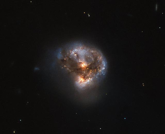
This galaxy has a far more exciting and futuristic classification than most — it hosts a megamaser. Megamasers are intensely bright, around 100 million times brighter than the masers found in galaxies like the Milky Way. The entire galaxy essentially acts as an astronomical laser that beams out microwave emission rather than visible light (hence the ‘m’ replacing the ‘l’). A megamaser is a process that involves some components within the galaxy (like gas) that is in the right physical condition to cause the amplification of light (in this case, microwaves). But there are other parts of the galaxy (like stars for example) that aren’t part of the maser process. This megamaser galaxy is named IRAS 16399-0937 and is located over 370 million light-years from Earth. This NASA/ESA Hubble Space Telescope image belies the galaxy’s energetic nature, instead painting it as a beautiful and serene cosmic rosebud. The image comprises observations captured across various wavelengths by two of Hubble’s instruments: the Advanced Camera for Surveys (ACS), and the Near Infrared Camera and Multi-Object Spectrometer (NICMOS). NICMOS’s superb sensitivity, resolution, and field of view gave astronomers the unique opportunity to observe the structure of IRAS 16399-0937 in detail. They found it hosts a double nucleus — the galaxy’s core is thought to be formed of two separate cores in the process of merging. The two components, named IRAS 16399N and IRAS 16399S for the northern and southern parts respectively, sit over 11,000 light-years apart. However, they are both buried deep within the same swirl of cosmic gas and dust and are interacting, giving the galaxy its peculiar structure. The nuclei are very different. IRAS 16399S appears to be a starburst region, where new stars are forming at an incredible rate. IRAS 16399N, however, is something known as a LINER nucleus (Low Ionization Nuclear Emission Region), which is a region whose emission mostly stems from weakly-ionized or neutral atoms of particular gases. The northern nucleus also hosts a black hole with some 100 million times the mass of the sun! Image credit: ESA/Hubble & NASA, Acknowledgement: Judy Schmidt (geckzilla) <b><a href="http://www.nasa.gov/audience/formedia/features/MP_Photo_Guidelines.html" rel="nofollow">NASA image use policy.</a></b> <b><a href="http://www.nasa.gov/centers/goddard/home/index.html" rel="nofollow">NASA Goddard Space Flight Center</a></b> enables NASA’s mission through four scientific endeavors: Earth Science, Heliophysics, Solar System Exploration, and Astrophysics. Goddard plays a leading role in NASA’s accomplishments by contributing compelling scientific knowledge to advance the Agency’s mission. <b>Follow us on <a href="http://twitter.com/NASAGoddardPix" rel="nofollow">Twitter</a></b> <b>Like us on <a href="http://www.facebook.com/pages/Greenbelt-MD/NASA-Goddard/395013845897?ref=tsd" rel="nofollow">Facebook</a></b> <b>Find us on <a href="http://instagrid.me/nasagoddard/?vm=grid" rel="nofollow">Instagram</a></b>
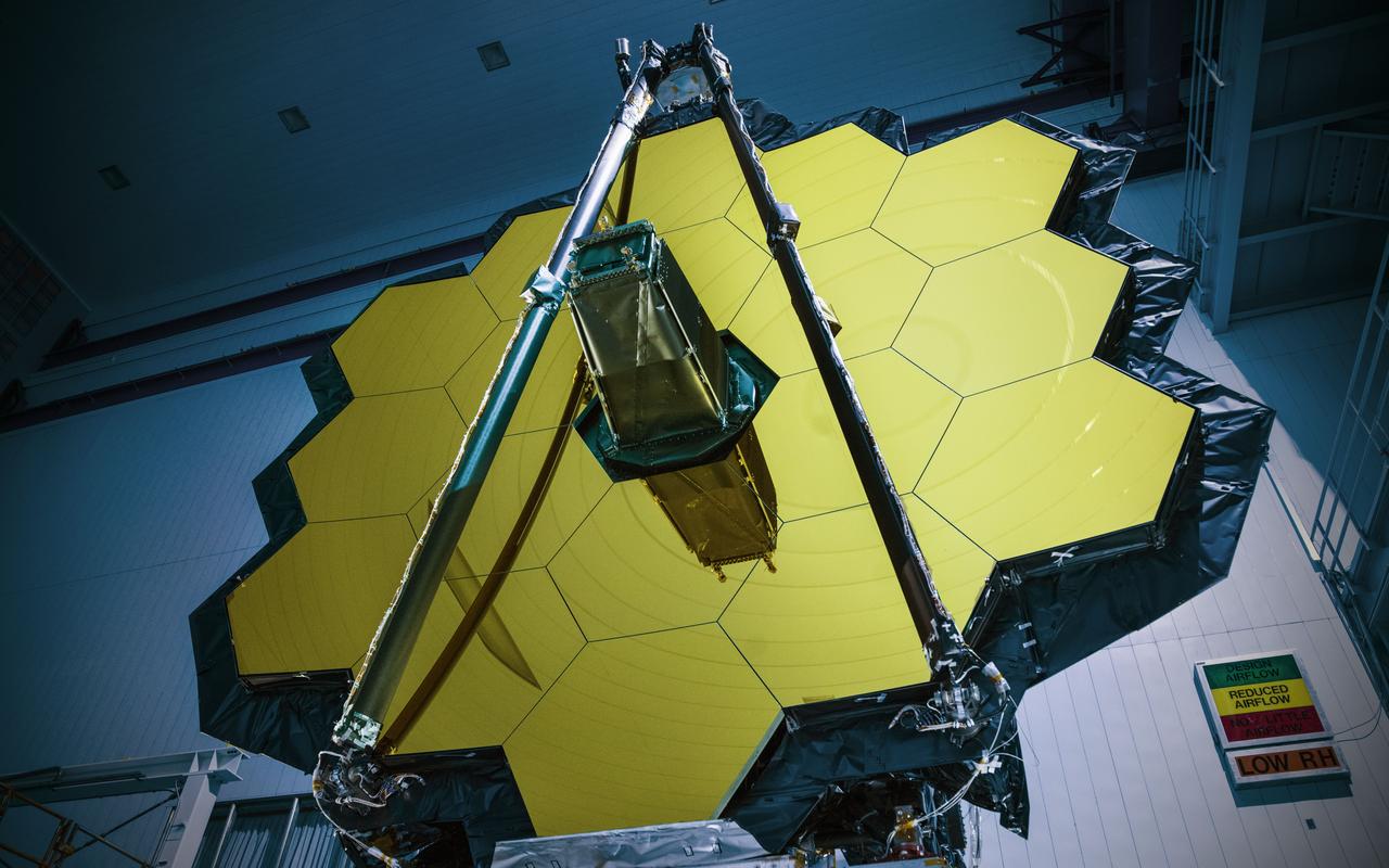
NASA’s James Webb Space Telescope has successfully passed the center of curvature test, an important optical measurement of Webb’s fully assembled primary mirror prior to cryogenic testing, and the last test held at NASA's Goddard Space Flight Center in Greenbelt, Maryland, before the spacecraft is shipped to NASA’s Johnson Space Center in Houston for more testing. After undergoing rigorous environmental tests simulating the stresses of its rocket launch, the Webb telescope team at Goddard analyzed the results from this critical optical test and compared it to the pre-test measurements. The team concluded that the mirrors passed the test with the optical system unscathed. “The Webb telescope is about to embark on its next step in reaching the stars as it has successfully completed its integration and testing at Goddard. It has taken a tremendous team of talented individuals to get to this point from all across NASA, our industry and international partners, and academia,” said Bill Ochs, NASA’s Webb telescope project manager. “It is also a sad time as we say goodbye to the Webb Telescope at Goddard, but are excited to begin cryogenic testing at Johnson.” Rocket launches create high levels of vibration and noise that rattle spacecraft and telescopes. At Goddard, engineers tested the Webb telescope in vibration and acoustics test facilities that simulate the launch environment to ensure that functionality is not impaired by the rigorous ride on a rocket into space. Before and after these environmental tests took place, optical engineers set up an interferometer, the main device used to measure the shape of the Webb telescope’s mirror. An interferometer gets its name from the process of recording and measuring the ripple patterns that result when different beams of light mix and their waves combine or “interfere.” Waves of visible light are less than a thousandth of a millimeter long and optics on the Webb telescope need to be shaped and aligned even more accurately than that to work correctly. Making measurements of the mirror shape and position by lasers prevents physical contact and damage (scratches to the mirror). So, scientists use wavelengths of light to make tiny measurements. By measuring light reflected off the optics using an interferometer, they are able to measure extremely small changes in shape or position that may occur after exposing the mirror to a simulated launch or temperatures that simulate the subfreezing environment of space. During a test conducted by a team from Goddard, Ball Aerospace of Boulder, Colorado, and the Space Telescope Science Institute in Baltimore, temperature and humidity conditions in the clean room were kept incredibly stable to minimize fluctuations in the sensitive optical measurements over time. Even so, tiny vibrations are ever-present in the clean room that cause jitter during measurements, so the interferometer is a “high-speed” one, taking 5,000 “frames” every second, which is a faster rate than the background vibrations themselves. This allows engineers to subtract out jitter and get good, clean results on any changes to the mirror's shape. Credit: NASA/Goddard/Chris Gunn Read more: <a href="https://go.nasa.gov/2oPqHwR" rel="nofollow">go.nasa.gov/2oPqHwR</a> NASA’s Webb Telescope Completes Goddard Testing