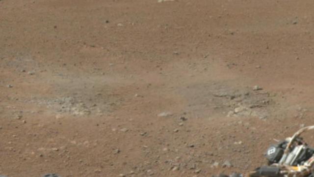
This cut-out from a color panorama image taken by NASA Curiosity rover shows the effects of the descent stage rocket engines blasting the ground. It comes from the left side of the thumbnail panorama obtained by Curiosity Mast Camera.
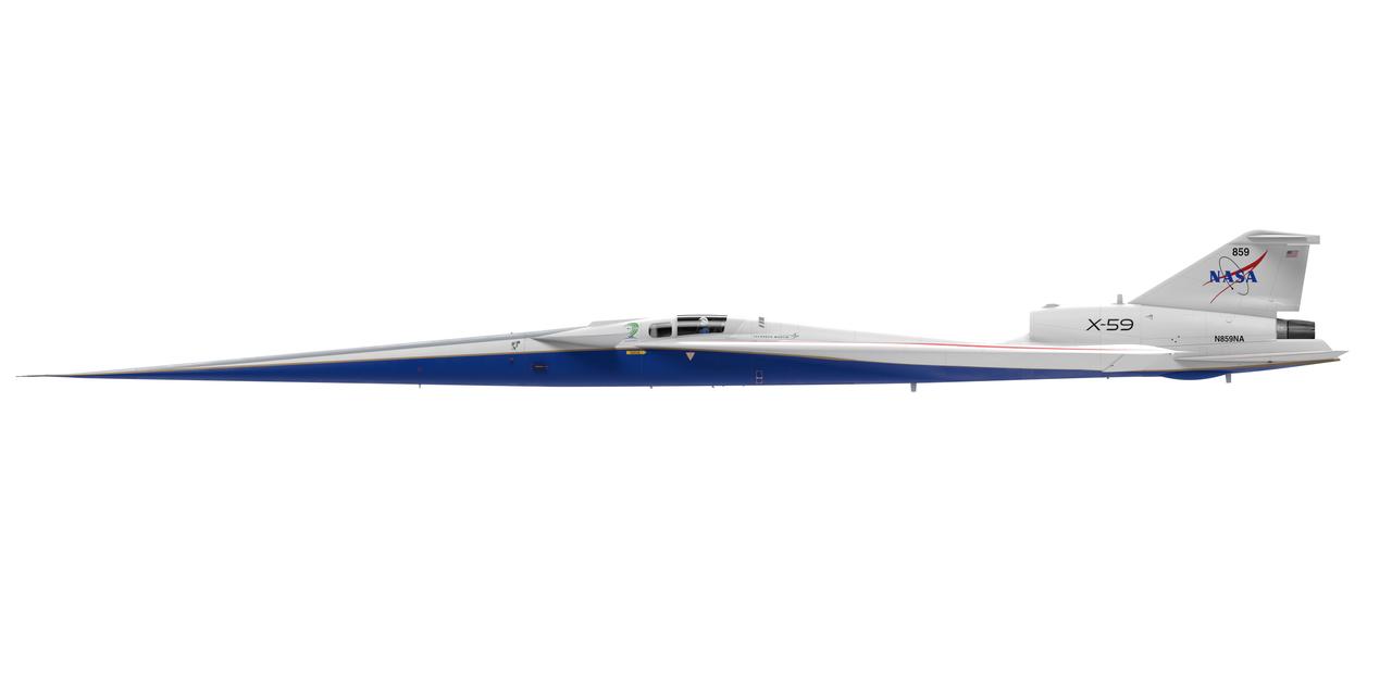
Artist concept of the X-59 side view (left side)
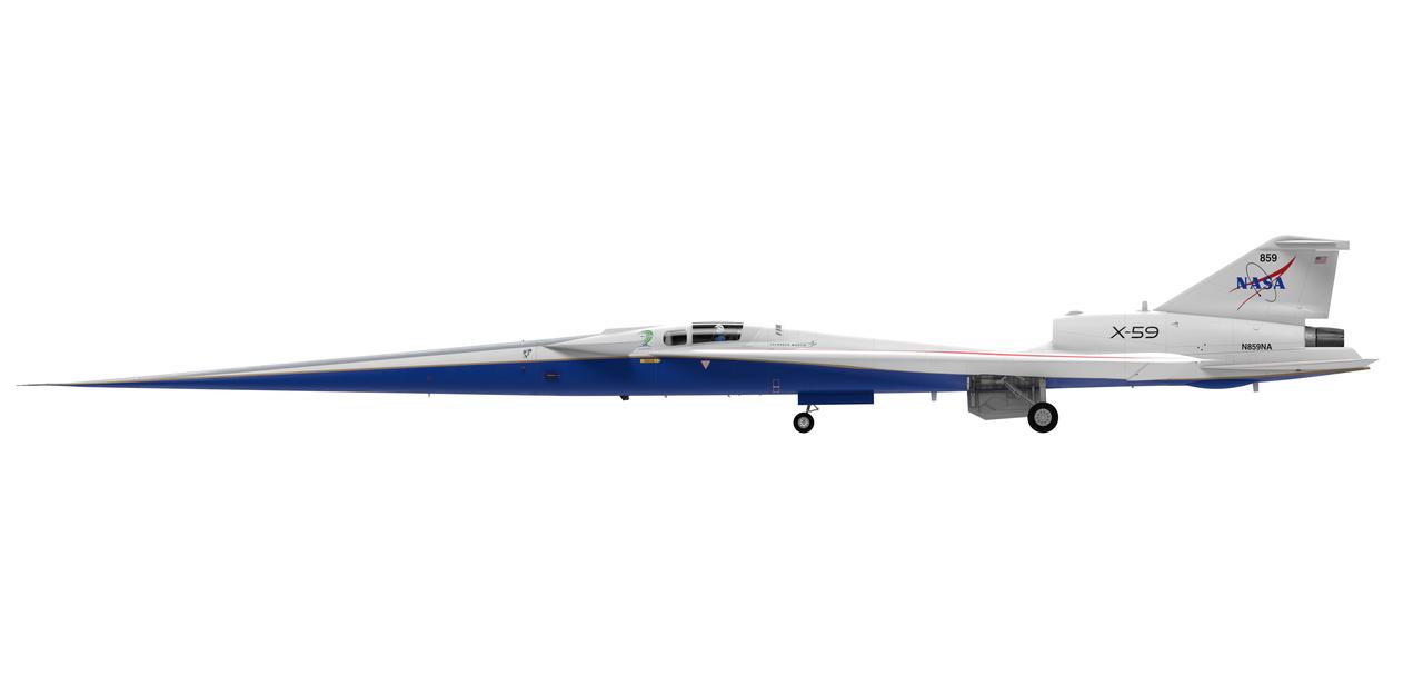
Artist concept of the X-59 side view (left side) with landing gears down.

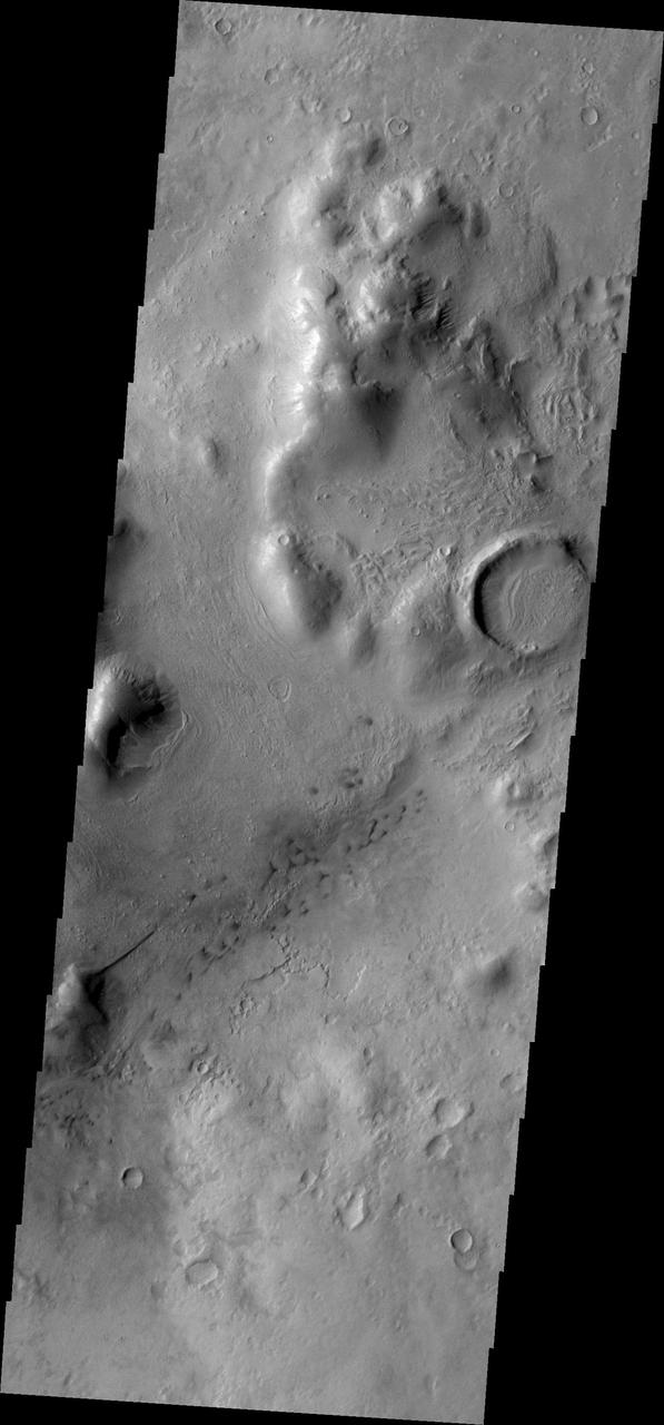
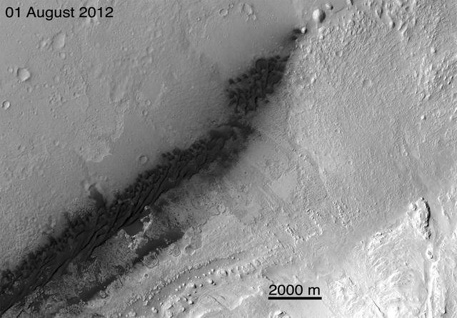
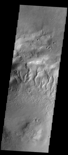
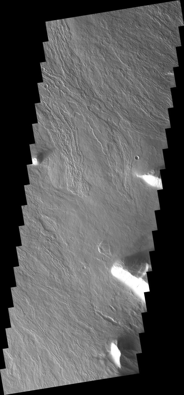
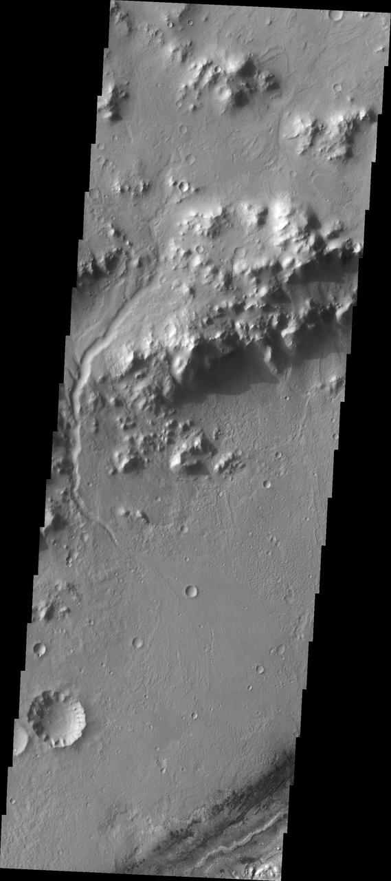
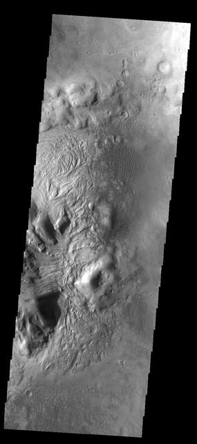
The eastern margin of Tharsis Tholus is visible on the left side of this image
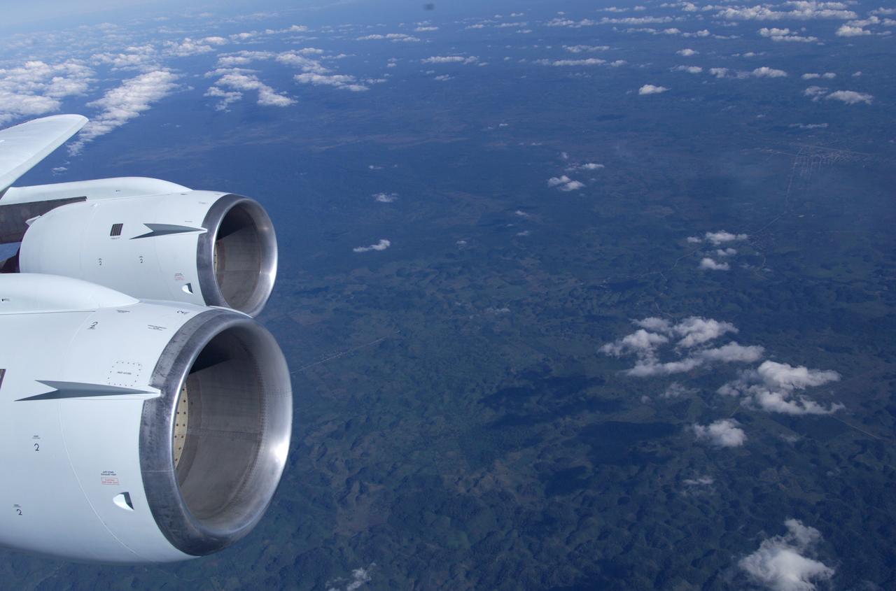
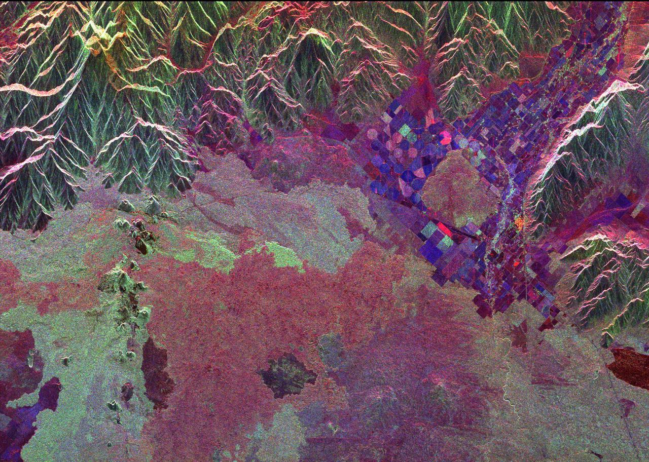
This is a photograph from the left side of the aircraft as NASA's DC-8 does an AirSAR 2004 research "line" over Honduras. AirSAR 2004 is a three-week expedition by an international team of scientists that will use an all-weather imaging tool, called the Airborne Synthetic Aperture Radar (AirSAR), in a mission ranging from the tropical rain forests of Central America to frigid Antarctica.
Do you see what I see in this image from NASA Mars Odyssey spacecraft? A long dune extends from the side of a hill on the bottom left side of this image. It looks like the beak of a humming bird.
This image from NASA Dawn spacecraft of asteroid Vesta shows Octavia crater, located in Vesta Marcia quadrangle, just south of Vesta equator. Octavia rim is fresher on the right side and more degraded on the left side.
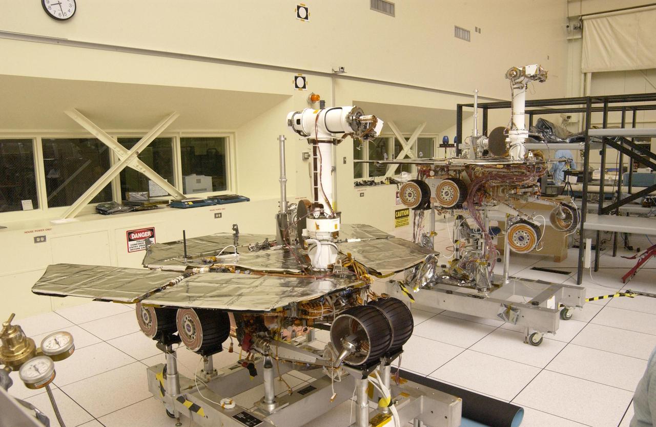
The twin rovers sit side-by-side in different stages of deployment. NASA Rover 2 left front wheels are stowed, while NASA Rover 1 front wheels are deployed.

In this side-by-side visualization, Pacific Ocean sea surface height anomalies during the 1997-98 El Niño left are compared with 2015 Pacific conditions right.

This side-by-side image shows a Cassini radar image on the left of what is the largest body of liquid ever found on Titan north pole, compared to Lake Superior on the right

Global map of crustal thickness of the moon derived from gravity data obtained by NASA GRAIL spacecraft. The lunar near side is represented on the left hemisphere. The far side is represented in the right hemisphere.

Side-by-side images depict NASA's Curiosity rover (left) and a moon buggy driven during the Apollo 16 mission. Moon buggies were used during the Apollo missions to carry astronauts, lunar samples and equipment. During the Apollo 17 mission, that equipment included the Traverse Gravimeter Experiment (TGE), a special instrument for measuring gravity. Curiosity wasn't sent to Mars with gravimeters, but it does have accelerometers that are used to navigate the rover. A paper in Science published on Jan. 31, 2019, details how these sensors were repurposed to measure the gravitational pull of Mount Sharp, the mountain Curiosity has been climbing since 2014. Movie available at https://photojournal.jpl.nasa.gov/catalog/PIA23041
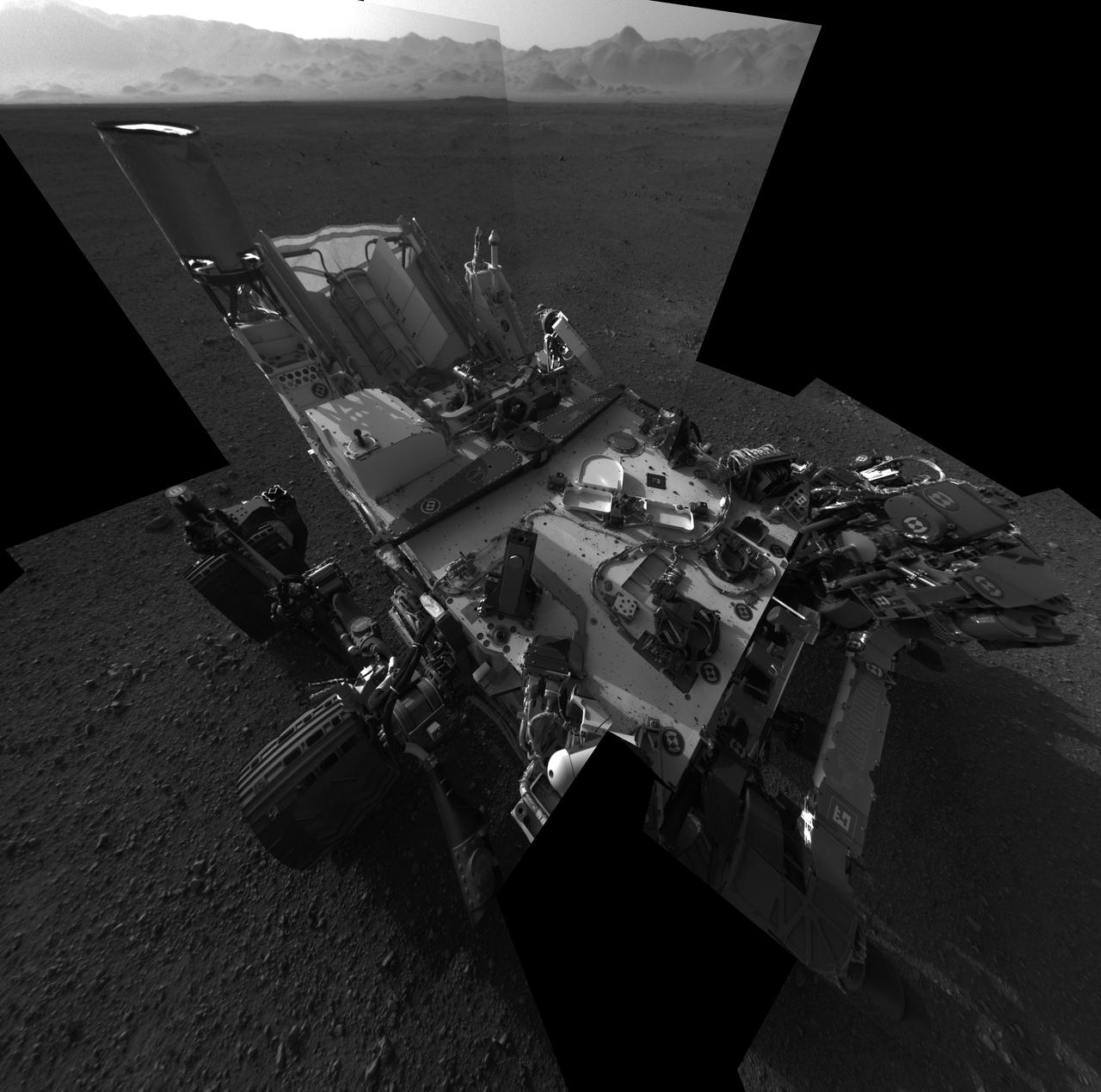
This full-resolution self-portrait shows the deck of NASA Curiosity rover. The back of the rover can be at top left, two of the right side wheels at left, and the undulating rim of Gale Crater forms the lighter color strip in the background.
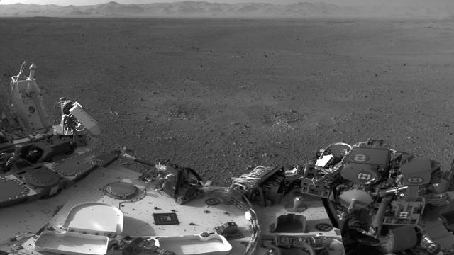
This mosaic image shows part of the left side of NASA Curiosity rover and two blast marks from the descent stage rocket engines. The rim of Gale Crater is the lighter colored band across the horizon. The back of the rover is to the left.
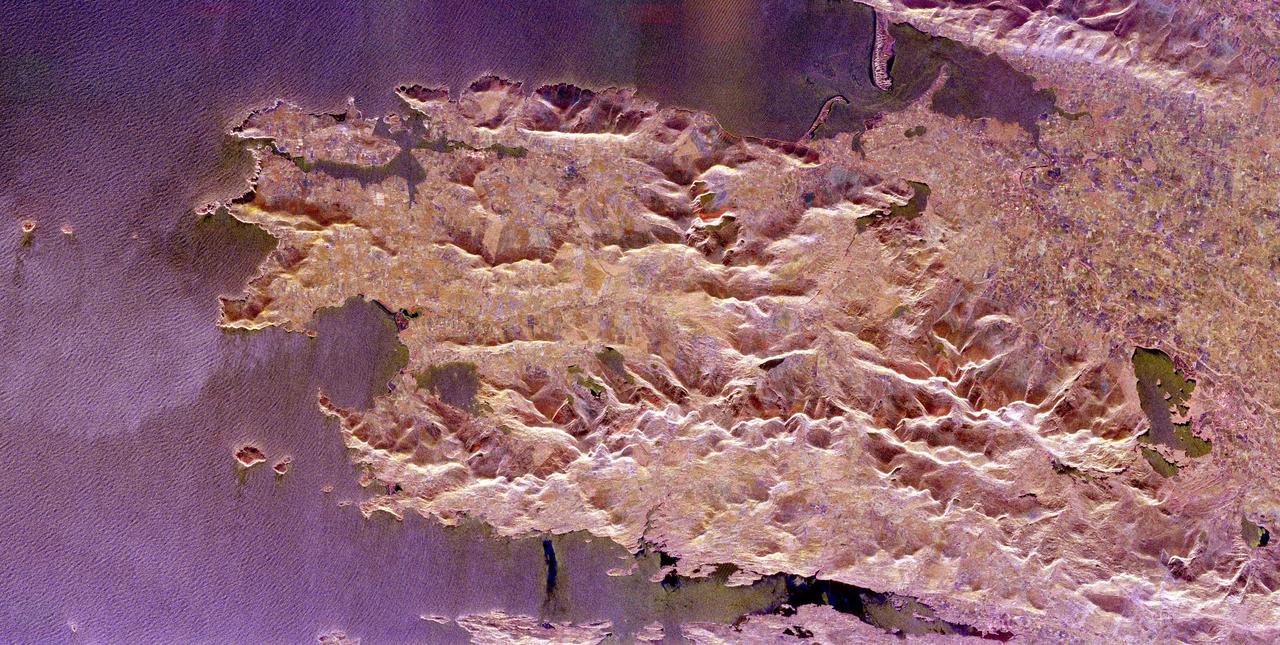
The Iveragh Peninsula, one of the four peninsulas in southwestern Ireland, is shown in this spaceborne radar image. The lakes of Killarney National Park are the green patches on the left side of the image.
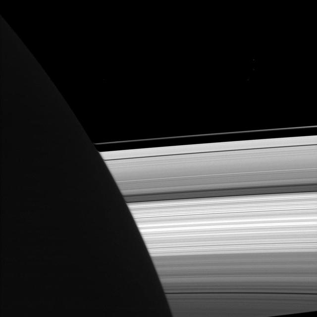
NASA Cassini spacecraft looks past the night side of Saturn, dimly lit on the left of this image by ringshine, for a subtly distorted view of the planet rings.

Part of the southern hemisphere on dwarf planet Ceres is seen in this image taken by NASA Dawn spacecraft. This left side of the image shows the eastern rim of Urvara crater.
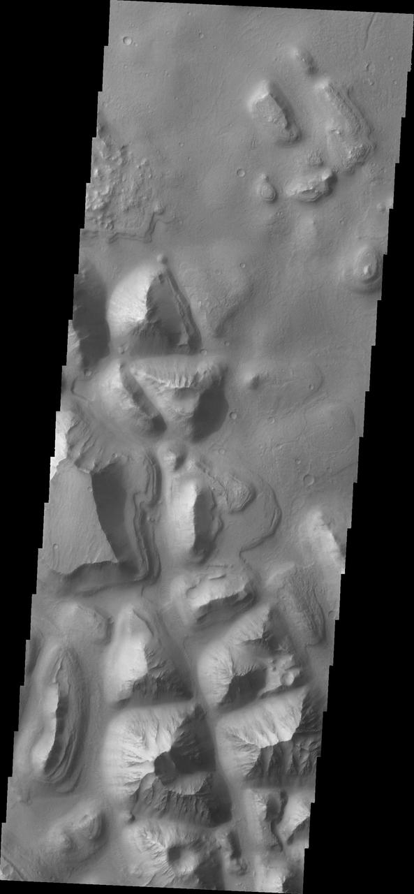
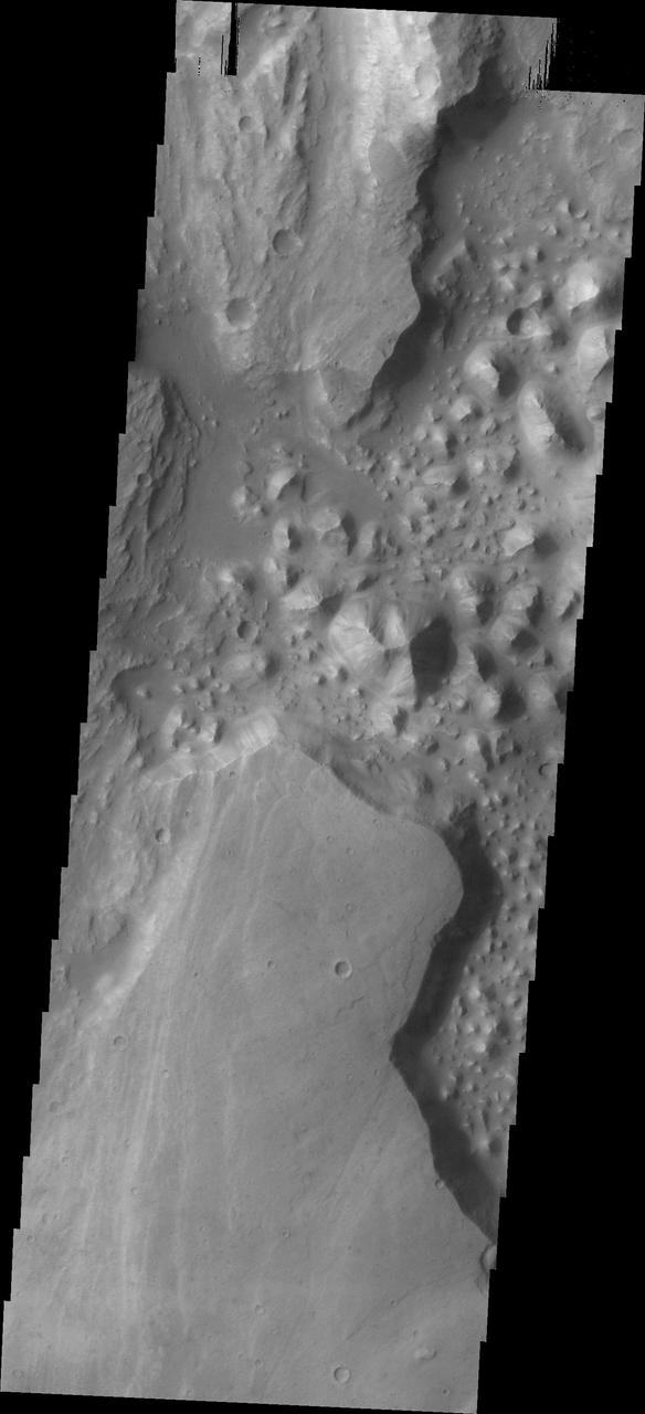
This image from NASA 2001 Mars Odyssey spacecraft shows a portion of Hydraotes Chaos. The individual hills on the left side of the image also appear to be layered.
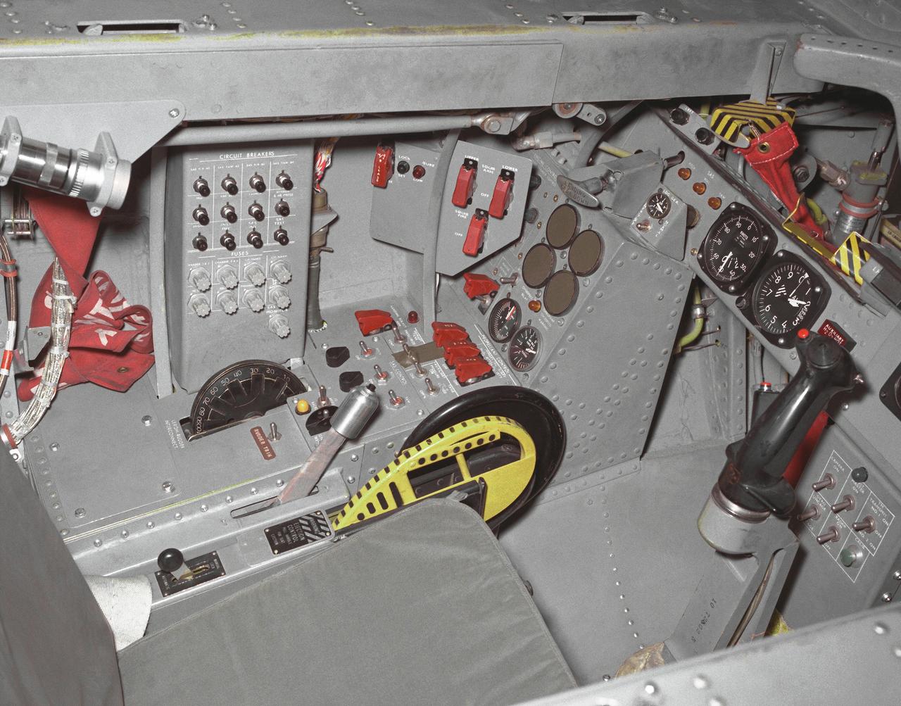
This photo shows the left side cockpit instrumentation panel of the M2-F2 Lifting Body. The success of Dryden's M2-F1 program led to NASA's development and construction of two heavyweight lifting bodies based on studies at NASA's Ames and Langley research centers -- the M2-F2 and the HL-10, both built by the Northrop Corporation. The "M" refers to "manned" and "F" refers to "flight" version. "HL" comes from "horizontal landing" and 10 is for the tenth lifting body model to be investigated by Langley. The first flight of the M2-F2 -- which looked much like the "F1" -- was on July 12, 1966. Milt Thompson was the pilot. By then, the same B-52 used to air launch the famed X-15 rocket research aircraft was modified to also carry the lifting bodies. Thompson was dropped from the B-52's wing pylon mount at an altitude of 45,000 feet on that maiden glide flight. The M2-F2 weighed 4,620 pounds, was 22 feet long, and had a width of about 10 feet. On May 10, 1967, during the sixteenth glide flight leading up to powered flight, a landing accident severely damaged the vehicle and seriously injured the NASA pilot, Bruce Peterson. NASA pilots and researchers realized the M2-F2 had lateral control problems, even though it had a stability augmentation control system. When the M2-F2 was rebuilt at Dryden and redesignated the M2-F3, it was modified with an additional third vertical fin -- centered between the tip fins -- to improve control characteristics. The M2-F2/F3 was the first of the heavy-weight, entry-configuration lifting bodies. Its successful development as a research test vehicle answered many of the generic questions about these vehicles. NASA donated the M2-F3 vehicle to the Smithsonian Institute in December 1973. It is currently hanging in the Air and Space Museum along with the X-15 aircraft number 1, which was its hangar partner at Dryden from 1965 to 1969.
This image shows two side-by-side streaks of wispy, white clouds against a dark gray sky moving from the middle of the frame toward the left. To their right are several fainter, laterally extending rays of wispy clouds moving in the same direction.

This image from NASA Wide-field Infrared Survey Explorer, shows three different nebulae located in the constellation of Perseus. NGC 1491 is seen on the right side of the image, SH 2-209 is on the left side and BFS 34 lies in between.
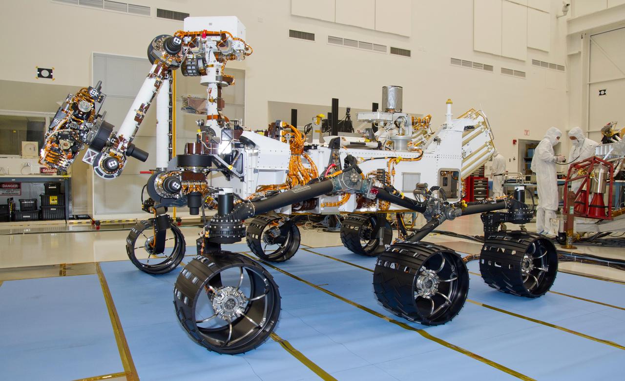
This photograph of the NASA Mars Science Laboratory rover, Curiosity, was taken during mobility testing on June 3, 2011. The location is inside the Spacecraft Assembly Facility at NASA Jet Propulsion Laboratory, Pasadena, Calif.

This image from NASA's Mars Reconnaissance Orbiter (MRO) shows two small impact craters located in Meridiani Planum. This is an example of the geologic principle of superposition: figuring out what happened first by looking at how features interact with each other. We can see that one of the craters must have hit the surface after the other was already there, but which came first? We can see that the ejecta blankets look rougher on the right side of the image than they do on the left. This could mean that the right side ejecta is newer, and has not been exposed to the wind as much as the left side has. Zooming in, we see small boulders on the floor and walls of the left-side crater, and they even seem to match the rough material in the ejecta on the right. With these clues, we can hypothesize that the crater on the left was here first. After some time another asteroid hit, formed the crater on the right, which threw material onto the floor of the left, where it remains to this day. https://photojournal.jpl.nasa.gov/catalog/PIA22454

iss058e013244 (Feb. 13, 2019) --- The forward end of the International Space Station is pictured showing portions of five modules. From right to left is a portion of the U.S. Destiny laboratory module linking forward to the Harmony module. Attached to the port side of Harmony (left foreground) is the Kibo laboratory module from the Japan Aerospace Exploration Agency (JAXA) with its logistics module berthed on top. On Harmony's starboard side (center background) is the Columbus laboratory module from ESA (European Space Agency).
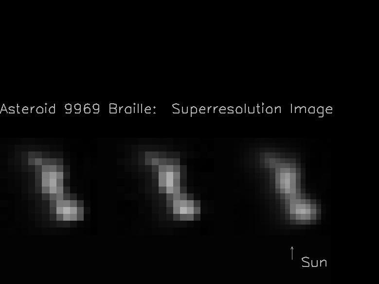
The two images on the left hand side of this composite image frame were taken 914 seconds and 932 seconds after the NASA Deep Space 1 encounter with the asteroid 9969 Braille. The image on the right was created by combining the two images on the left.
This image from an animation is from NASA Mars Reconnaissance Orbiter MRO showing the landing effects of the descent stage, the rover lander, the back shell and parachute, and the heat shield, all found on the left side of the image.
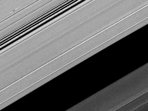
A bright spoke extends across the unilluminated side of Saturn B ring about the same distance as that from London to Cairo. The background ring material displays some azimuthal i.e., left to right asymmetry
The hills chaos in this image from NASA 2001 Mars Odyssey spacecraft are located between Stege Crater, just outside of the image to the northeast, and Maja Valles left side of image.
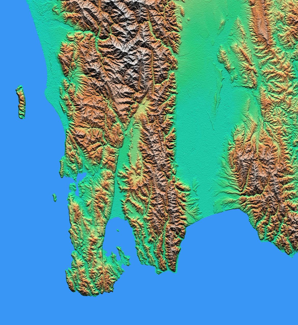
The topography of New Zealand North Island is rich in seismic features: The sharp line cutting through the city of Wellington on the left side of the large bay on the bottom coast is the active Wellington Fault.
Many gullies are located on the northern rim of this unnamed crater in Noachis Terra as seen by NASA 2001 Mars Odyssey spacecraft. Small dunes are located on the floor of the crater lower left side of image.
This shaded relief view from NASA New Horizons of the region surrounding the left side of Pluto heart-shaped feature, informally named Sputnik Planum, shows that the vast expanse of its icy surface.
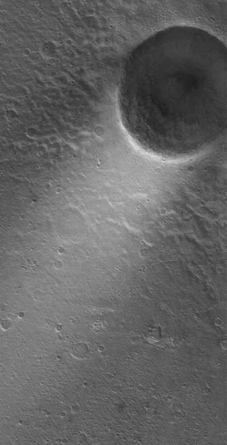
This MOC image shows a wind streak created in the lee -- the downwind side -- of a crater in far eastern Chryse Planitia. The winds responsible for the formation of the streak blew from the upper right northeast to the lower left southwest
NASA Cassini spacecraft observes three of Saturn moons set against the darkened night side of the planet. Seen here are Rhea, closest to Cassini, Enceladus to right of Rhea, and Dione, left of Rhea.
This image from NASA 2001 Mars Odyssey spacecraft shows just a small part of the eastern flank of Olympus Mons. On the far left side of the image a small volcanic cone can be seen. The shadow helps to identify this feature.
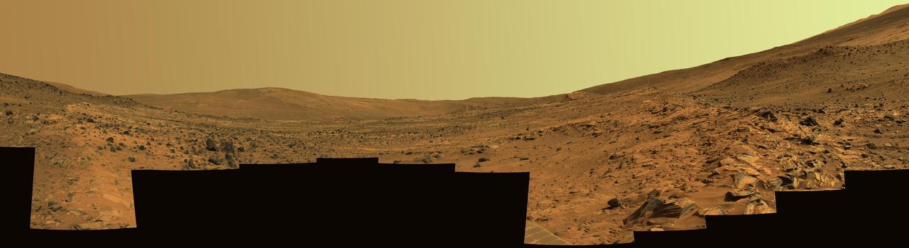
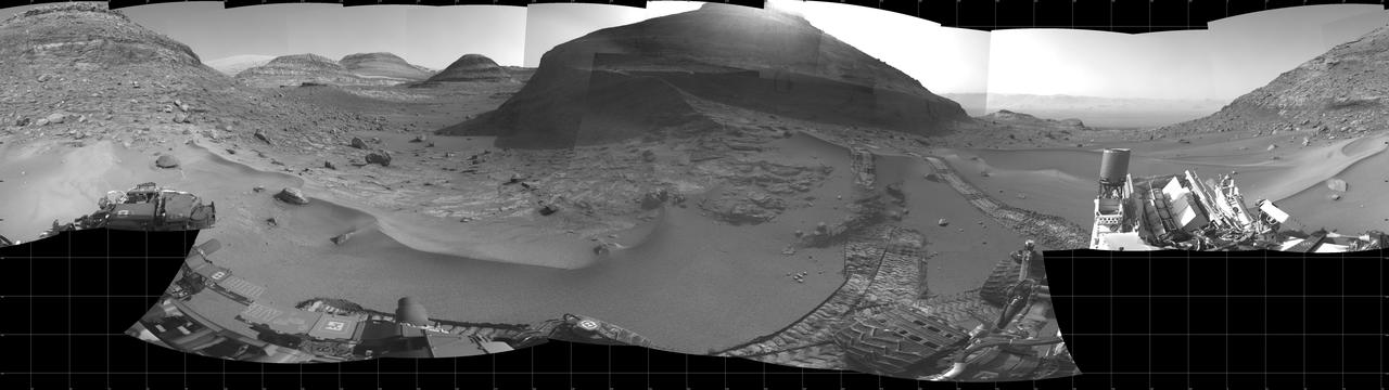
This panorama shows two reddish-brown, rock-strewn slopes on the left and right sides of a broad, U-shaped dip in the middle. In the distance are the broad slopes of McCool Hill. Above that is an orangish-yellow sky.
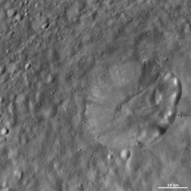
The left side of Helena crater on asteroid Vesta has a fresh and distinctive rim. Dark and bright material crops out of this part of the rim and slumps towards the center of the crater in this image from NASA Dawn spacecraft.
A propeller-shaped structure created by an unseen moon appears dark in this image obtained by NASA Cassini spacecraft of the unilluminated side of Saturn rings. The propeller is marked with a red arrow in the top left.

A 300-mile-long linear gravity anomaly on the far side of the moon has been revealed by gravity gradients measured by NASA GRAIL mission. GRAIL data are shown on the left, with red and blue corresponding to stronger gravity gradients.
This image captured by NASA 2001 Mars Odyssey spacecraft contains the landing site in the bottom right portion of the image, near the dark dunes. Note the channel that cuts through the crater rim on the left side of the image.
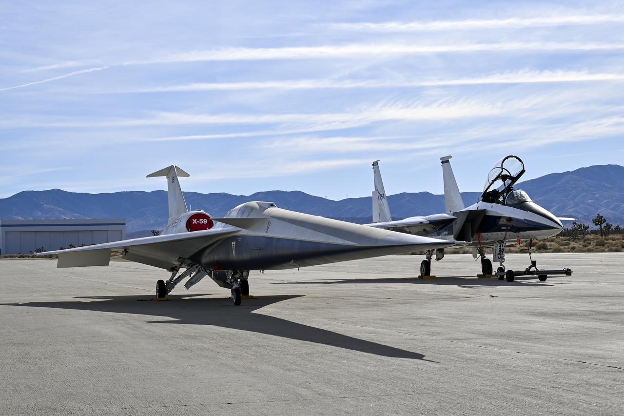
A NASA F-15 aircraft sits 20 feet off the left side of the X-59 aircraft, with a white hangar and hills in the background, during electromagnetic interference testing.
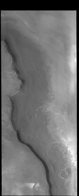
The cliff face in this image captured by NASA 2001 Mars Odyssey spacecraft is called Rupes Tenius rupes = scarp. The polar cap is the higher region to the left and the plains are located on the right side of the image.
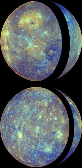
NASA MESSENGER shows the thin crescent of Mercury during approach forming the right portion of the globe and the fuller departure view showing Caloris basin forming the left side and majority of the view.
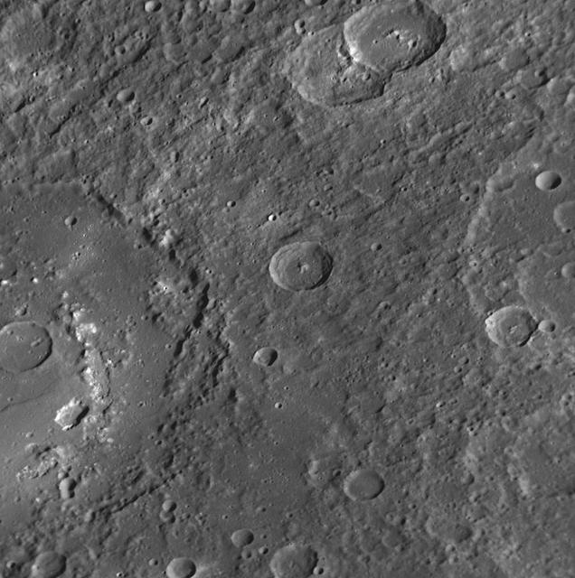
The large crater extending out the left side of this image is Praxiteles. Named for the ancient Greek sculptor of the 4th century BC, Praxiteles crater was first observed by Mariner 10.
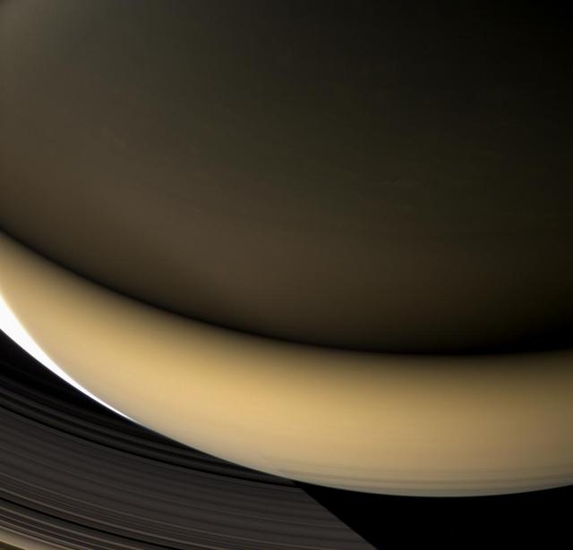
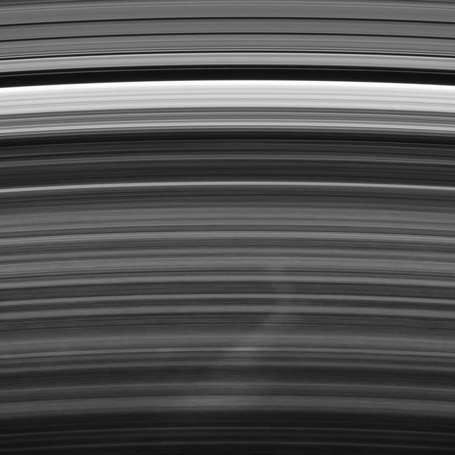
Large regions of Saturn night side are illuminated by the planet gleaming rings. Except for a sliver of the sunlit crescent at left, this view shows a part of the planet lit almost entirely by ringshine.
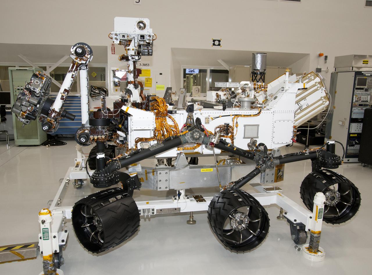
The rover for NASA Mars Science Laboratory mission, named Curiosity, is about 3 meters 10 feet long, not counting the additional length that the rover arm can be extended forward. The front of the rover is on the left in this side view.
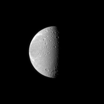
The tortured terrain of Saturn moon Dione is documented in this NASA Cassini spacecraft image. The wispy fractures on the moon trailing hemisphere can be seen on the left, and cratered terrain on the moon anti-Saturn side dominates the center.
Ancient lava flows dating back 2,000 to 15,000 years are shown in light green and red on the left side of this space radar image of the Craters of the Moon National Monument area in Idaho.
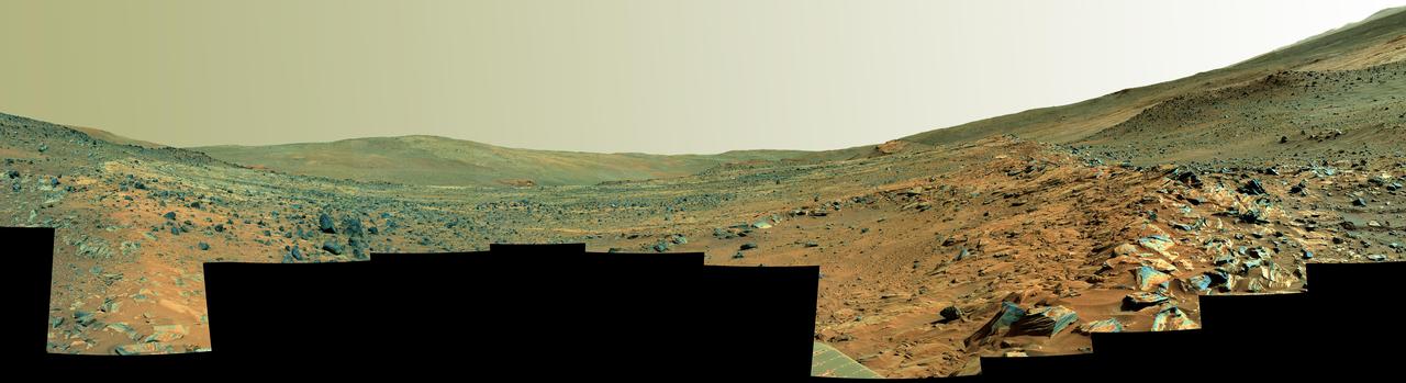
This panorama shows two rock-strewn slopes on the left and right sides of a broad, U-shaped dip in the middle. The sandy surface in front of the rover is reddish brown; individual rocks and more distant features are blue-gray
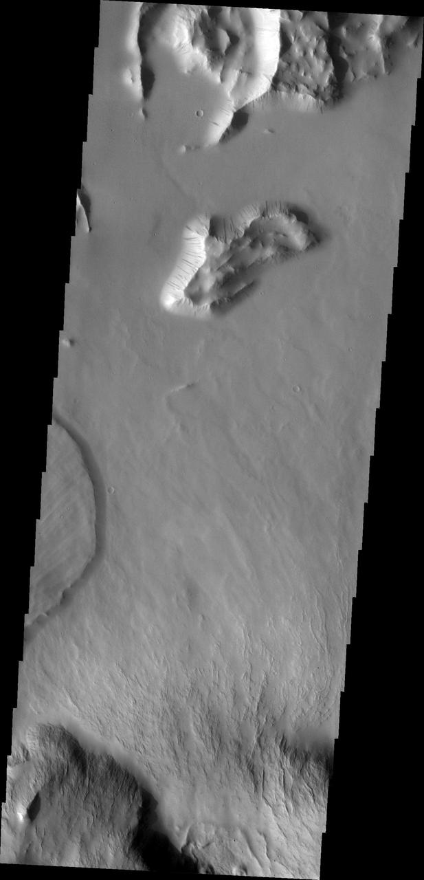
This image from NASA Mars Odyssey shows a small portion of the northern escarpment of Olympus Mons. The semi-circular deposit on the left side of the frame is a large landslide deposit.
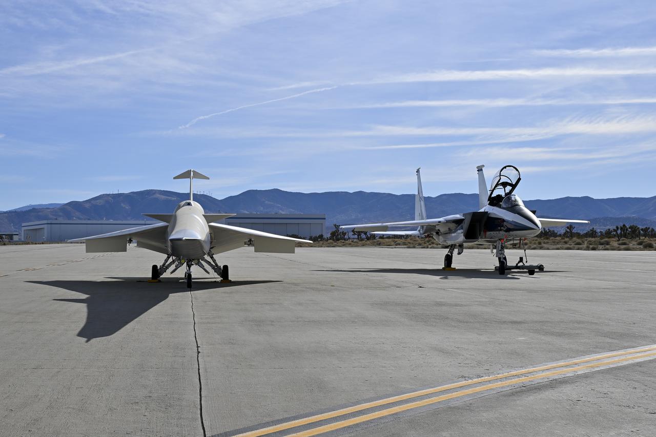
A NASA F-15 aircraft sits 20 feet off the left side of the X-59 aircraft, with a white hangar and hills in the background, during electromagnetic interference testing.
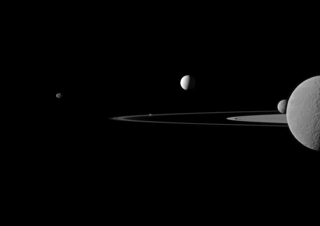
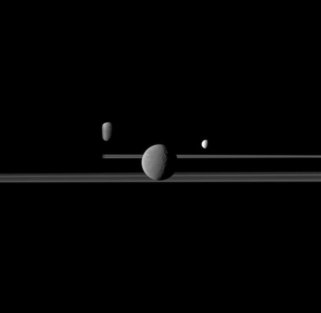
A quintet of Saturn moons come together in this portrait from NASA Cassini spacecraft. Janus is seen on the far left, Pandora orbits near the middle, Enceladus appears above the center, and Rhea and Mimas are seen on the right side.
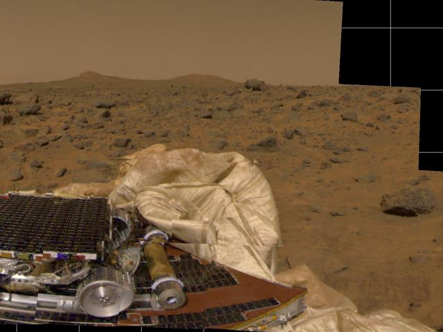
The Imager for Mars Pathfinder (IMP) took this image of surrounding terrain in the mid-morning on Mars (2:30 PM Pacific Daylight Time) earlier today. Part of the small rover, Sojourner, is visible on the left side of the picture. The tan cylinder to the right of the rover is one of two rolled-up ramps by which the rover will descend to the ground. The white, billowy material in the center of the picture is part of the airbag system. Many rocks of different shapes and sizes are visible between the lander and the horizon. Two hills are visible on the horizon. The notch on the left side of the leftmost conical hill is an artifact of the processing of this picture. http://photojournal.jpl.nasa.gov/catalog/PIA00613
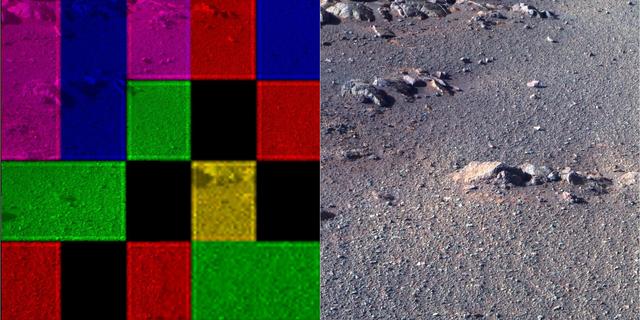
These side-by-side images were taken by the Pan Camera (Pancam) on NASA's Opportunity rover. They're actually the same image; the left version is how the image originally came down, due to data dropouts. The right shows the same image after processing all the data. The image is from the 4,493rd Martian day, or sol, of the mission. https://photojournal.jpl.nasa.gov/catalog/PIA23248
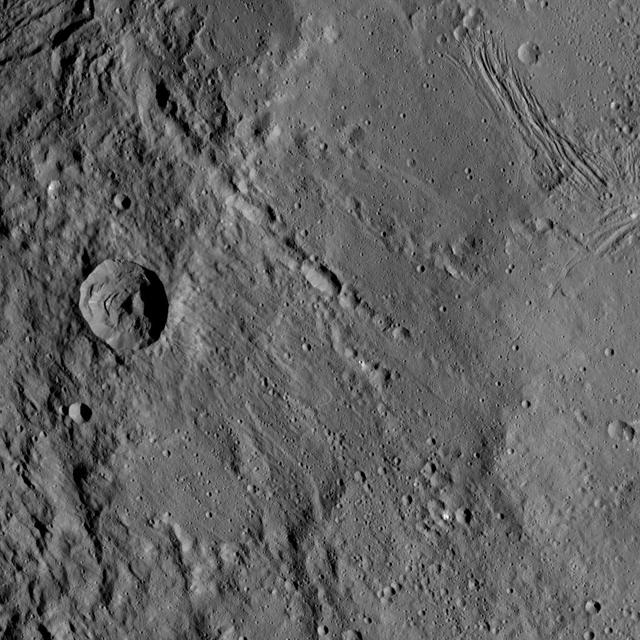
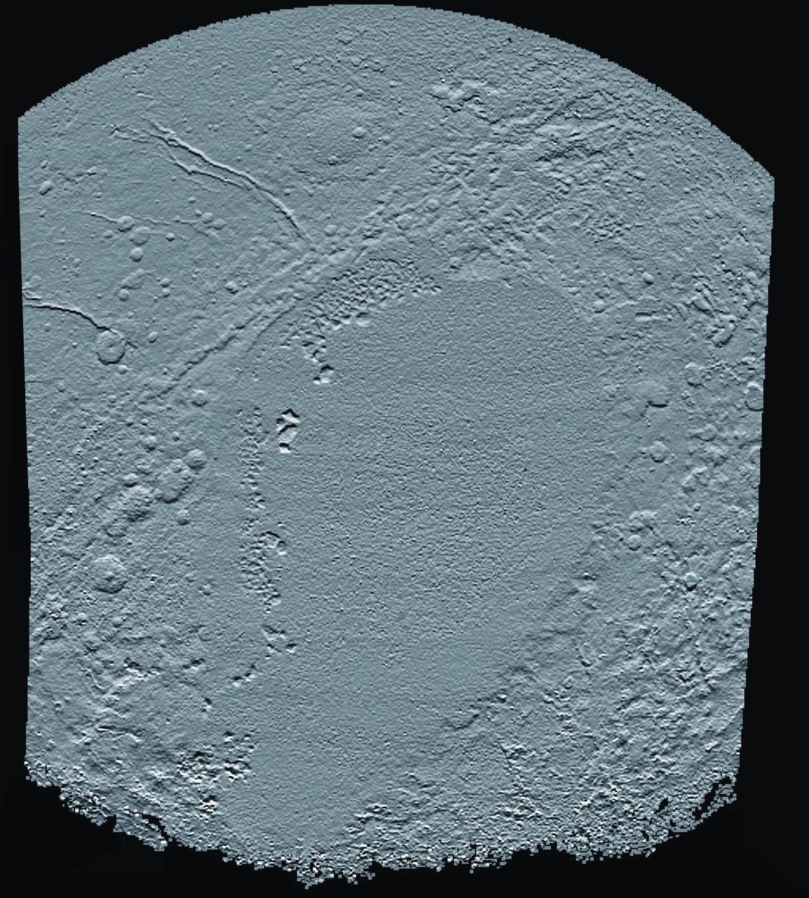
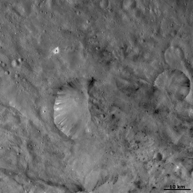
This view from NASA's Dawn spacecraft shows different types of terrain located side by side on Ceres: a smooth terrain at right with numerous small impact craters, and a less-cratered, hummocky terrain at left. A huge crater chain crosses the scene diagonally from upper left to lower right. The smooth terrain, which is in the western part of Yalode impact basin, is interrupted by a set of roughly parallel furrows and ridges at upper right. These linear features are perpendicular to another set of smaller, fainter linear markings, which appear just below them. An impact into the hummocky terrain formed a crater, seen at left, 14 miles (22 kilometers) in diameter with a central peak. A great deal of material has slumped down the walls of the crater -- a phenomenon called mass wasting. The crater's impact ejecta forms a smooth blanket around its rim, which takes on a streaky texture leading away from the crater toward lower right. The image was taken during in Dawn's High Altitude Mapping Orbit (HAMO) phase from an altitude of 911 miles (1,466 kilometers) on Oct. 6, 2015. Image resolution is 394 feet (120 meters) per pixel. The image is centered at 37 degrees south latitude, 279 degrees east longitude. http://photojournal.jpl.nasa.gov/catalog/PIA20133
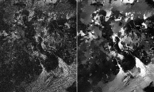
Presented here are side-by-side comparisons of a traditional Cassini Synthetic Aperture Radar (SAR) view, at left, and one made using a new technique for handling electronic noise that results in clearer views of Titan's surface, at right. The technique, called despeckling, produces images that can be easier for researchers to interpret. The terrain seen here is in the flow region named Leilah Fluctus (55 degrees north, 80 degrees west). With the speckle noise suppressed, the overall pattern of bright and dark in the scene becomes more apparent. In particular, cone-shaped features near lower right stand out, which could be alluvial analogues on Titan -- features produced by the action of rivers or floods. North is toward right in this image, which shows an area about 50 miles (80 kilometers) wide. http://photojournal.jpl.nasa.gov/catalog/PIA19054
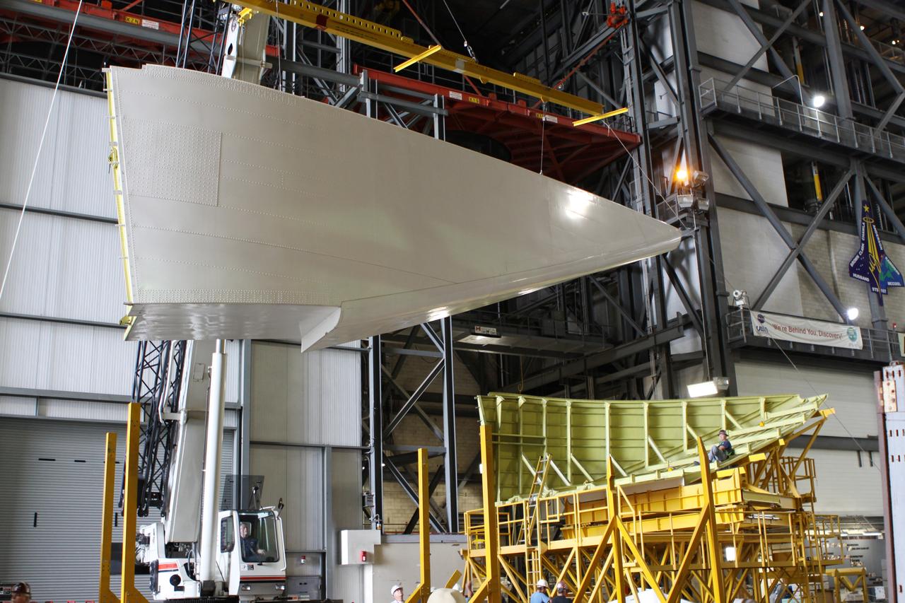
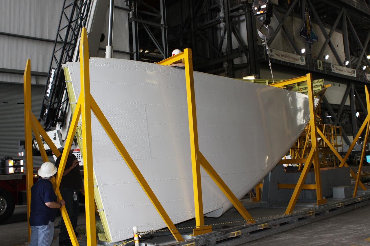
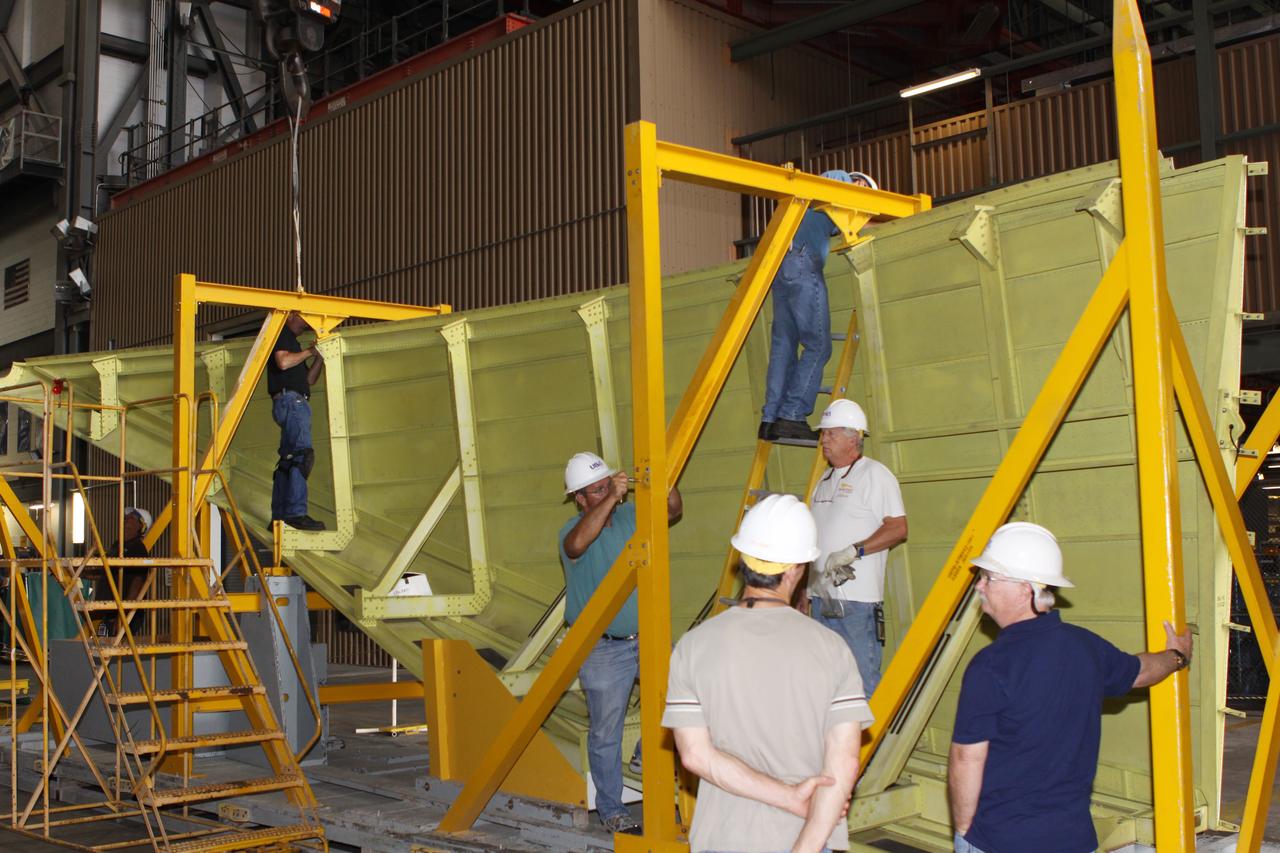
T&R Endeavour Left Side Tail Cone Buildup
T&R Endeavour Left Side Tail Cone Buildup
T&R Endeavour Left Side Tail Cone Buildup

T&R Endeavour Left Side Tail Cone Buildup
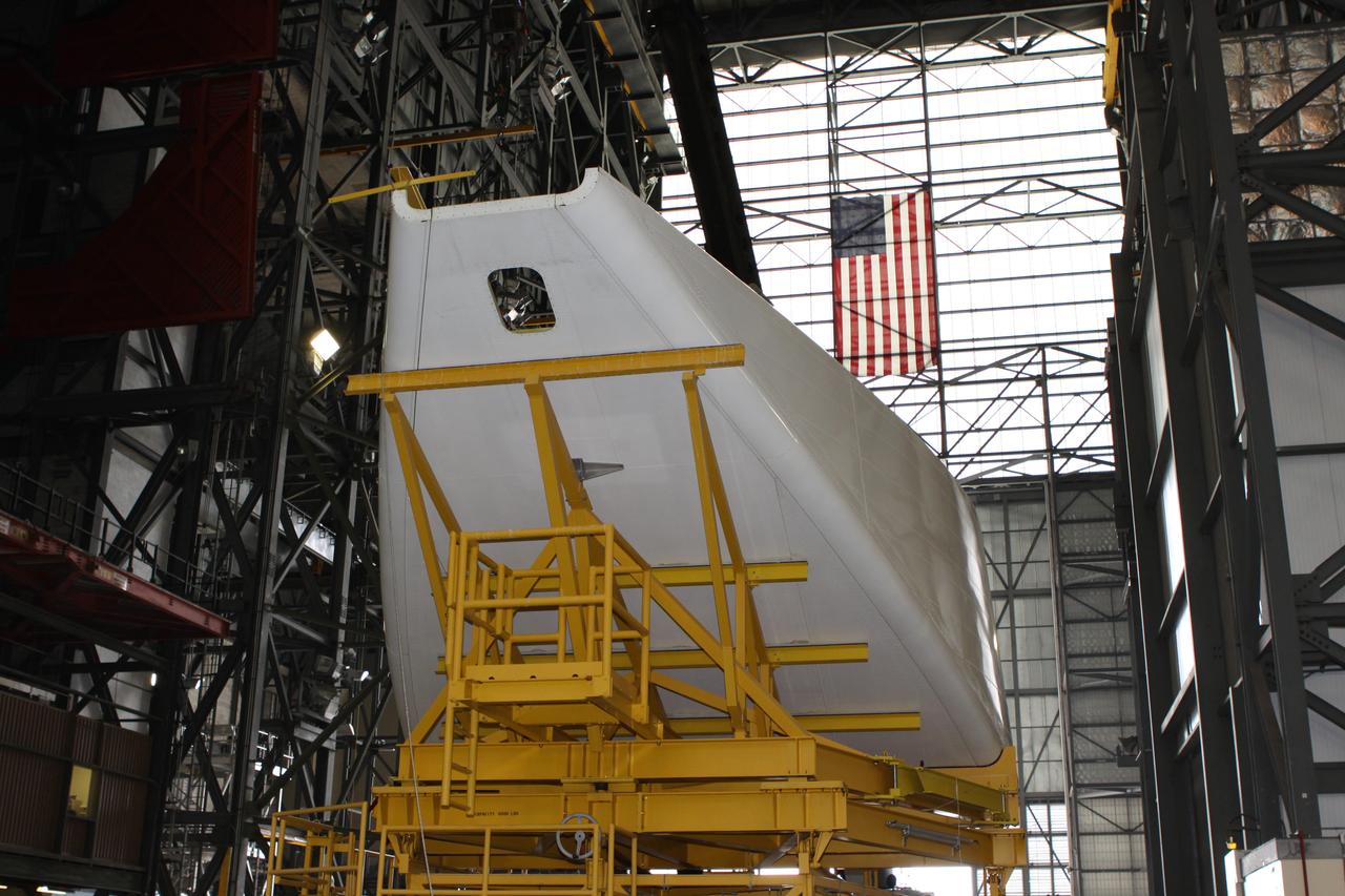
T&R Endeavour Left Side Tail Cone Buildup
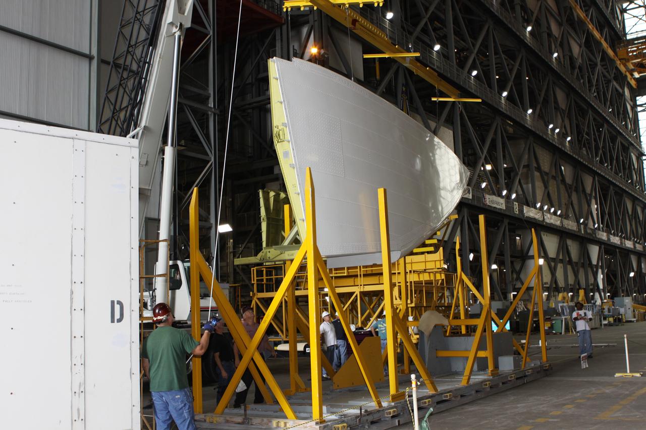
T&R Endeavour Left Side Tail Cone Buildup
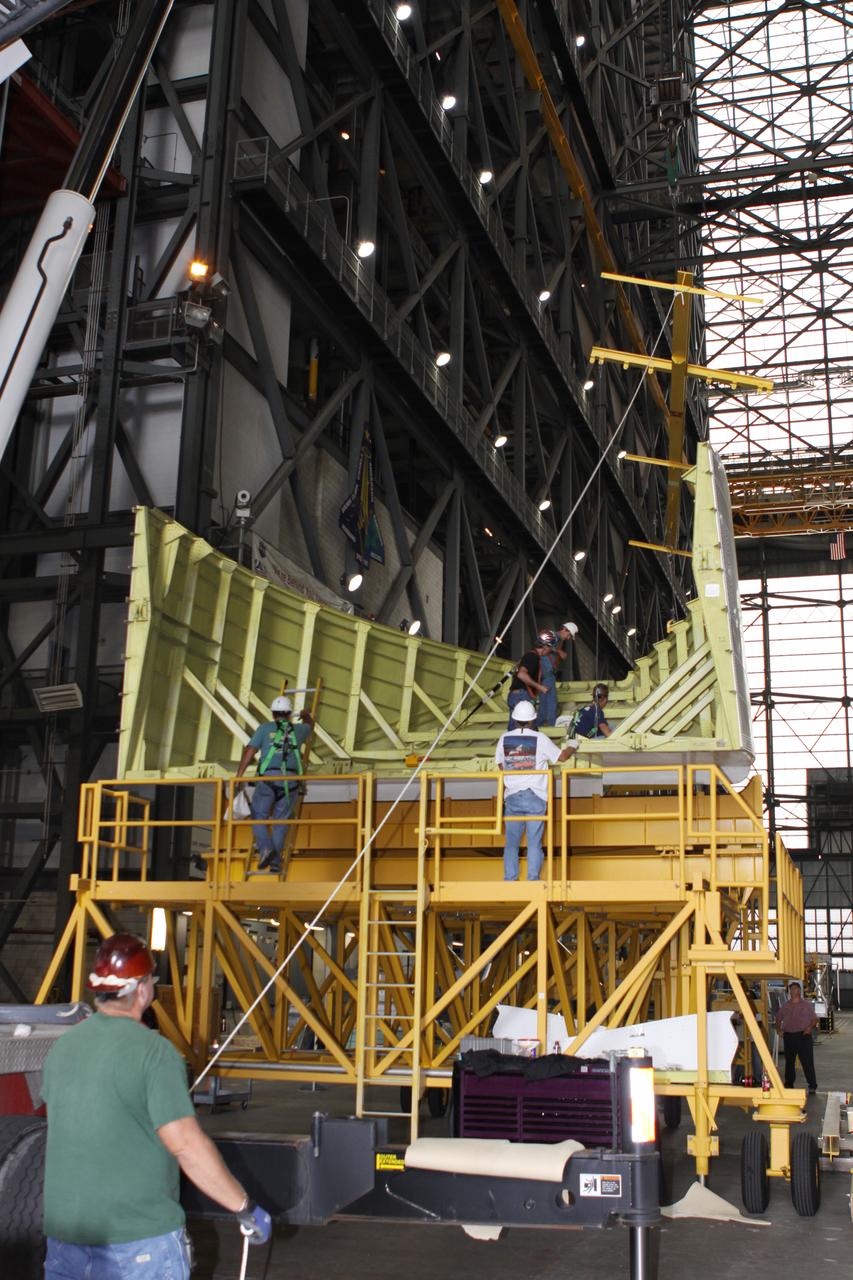
T&R Endeavour Left Side Tail Cone Buildup

jsc2024e006088 (1/18/2024) --- Some members from MicroOrbiter-1 team were performing a long range communication test within University Campus with the satellite side, while the Ground Terminal side was on the other side .From left to right : ABBAS Yasir, MOUMNI Fahd...Image Credit: MOUMNI Fahd.
View of the right cockpit of the F-111 MAW aircraft. Unlike most fighter aircraft of the time, the F-111 had side-by-side seating. The pilot sat on the left side, and the weapons systems officer on the right. Both had control sticks to fly the aircraft.
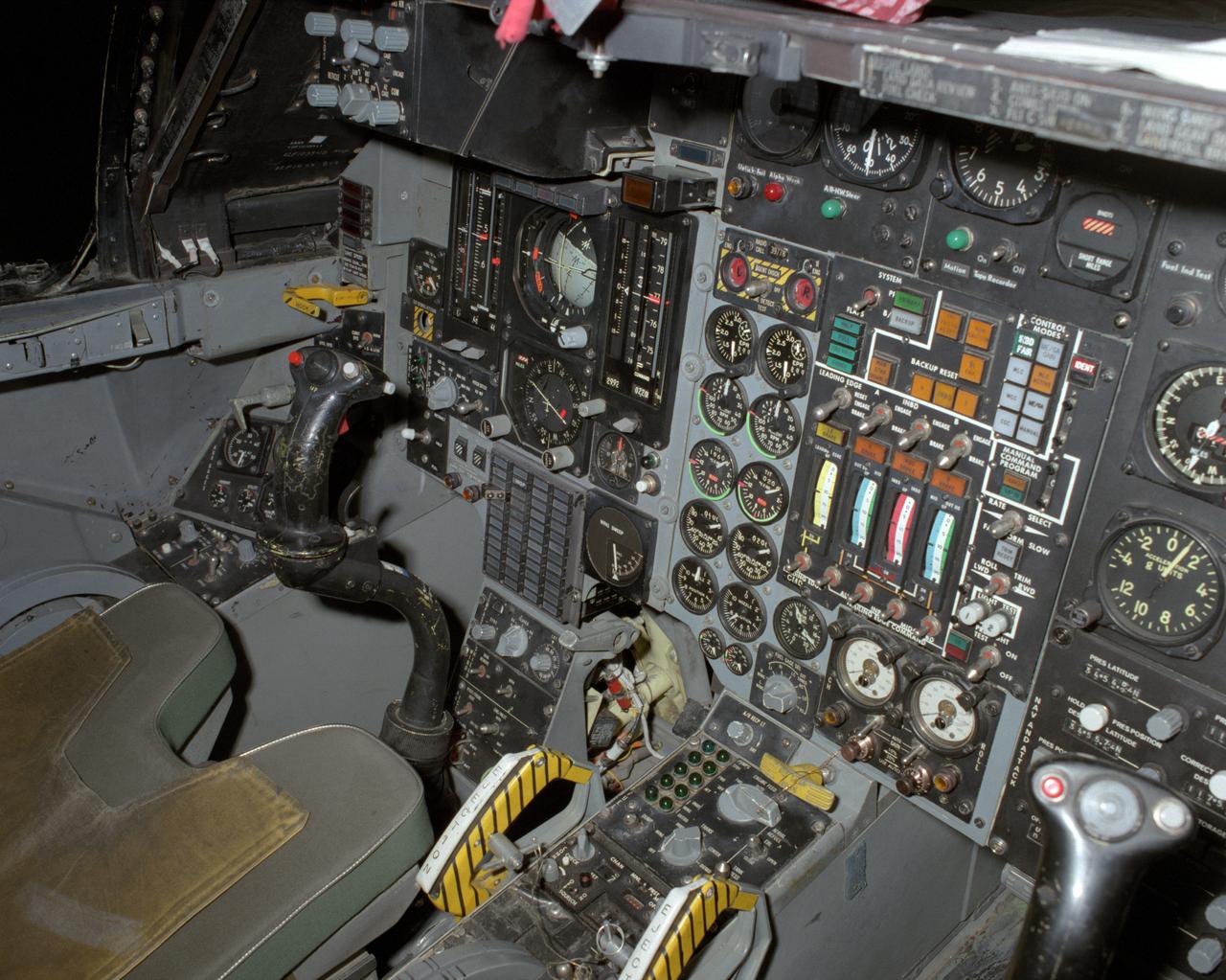
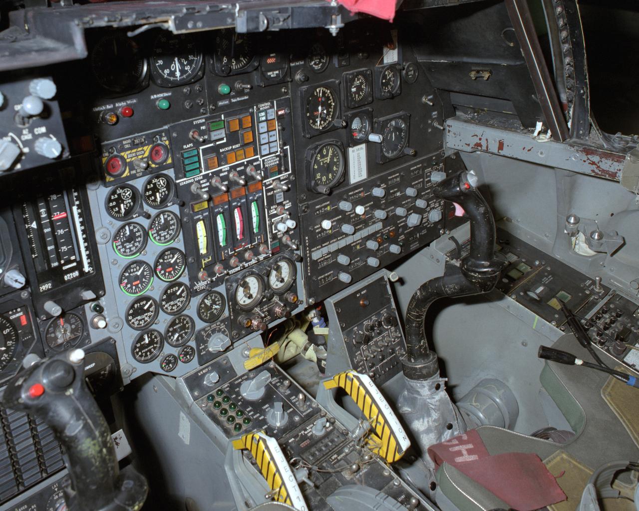
View of the left cockpit and pilot's seat of the F-111 MAW aircraft. Unlike most fighter aircraft of the time, the F-111 had side-by-side seating. The pilot sat on the left side, and the weapons systems officer on the right. Both had control sticks to fly the aircraft. The two yellow and black striped handles would be used in an emergency to eject the entire F-111 cockpit. The F-111 also did not have ejection seats, but used a capsule.
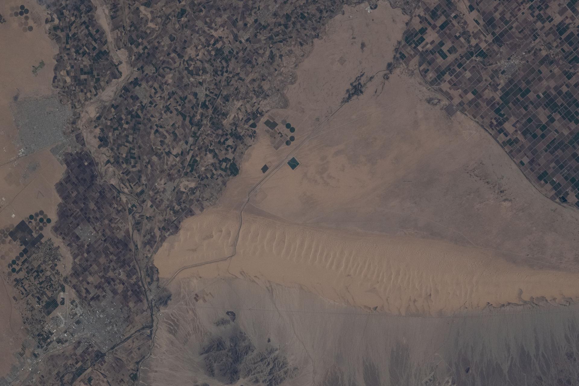
iss073e0886792 (Oct. 1, 2025) --- The Mexico–United States border separates Baja California (left) on the Mexican side from California (right) on the U.S. side in this photograph from the International Space Station as it orbited 261 miles above. This region is part of the Sonoran Desert, with the Algodones Dunes prominently visible on the U.S. side. Near upper left, is the Mexican city of San Luis Río Colorado with a population of about 177,000.
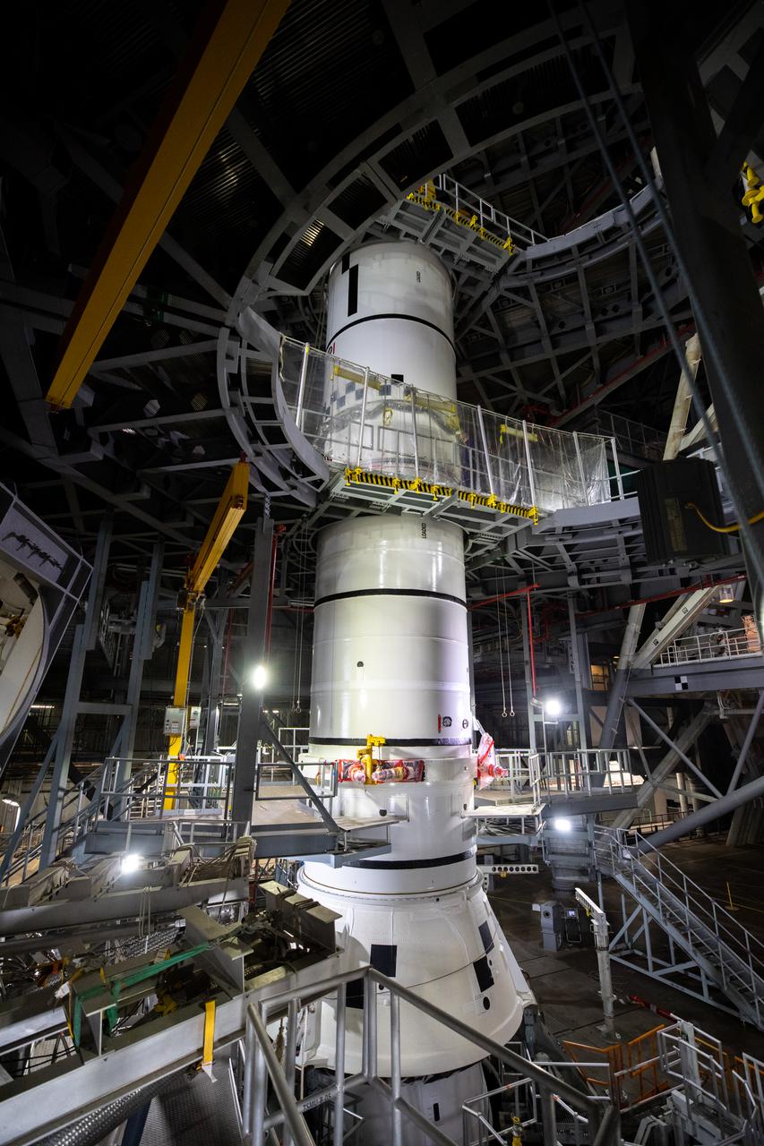
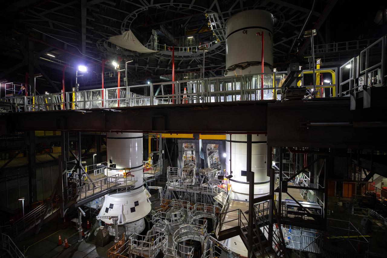
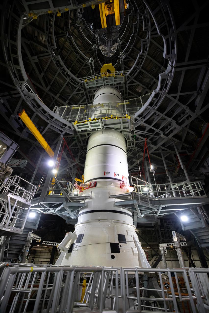
In High Bay 3 of the Vehicle Assembly Building at NASA’s Kennedy Space Center in Florida, the left-hand center booster segment for Artemis I is lowered onto the aft booster segment on the mobile launcher for the Space Launch System (SLS) on Jan. 7, 2021. Workers with Exploration Ground Systems and contractor Jacobs teams will stack the twin five-segment boosters on the mobile launcher in High Bay 3 over a number of weeks. When the core stage arrives, it will join the boosters on the mobile launcher, followed by the interim cryogenic propulsion stage and Orion spacecraft. Manufactured by Northrop Grumman in Utah, the twin boosters provide more than 75 percent of the total SLS thrust at launch. The SLS is managed by Marshall Space Flight Center in Huntsville, Alabama. Under the Artemis program, NASA will land the first woman and the next man on the Moon by 2024. The first in a series of increasingly complex missions, Artemis I will test the Orion spacecraft and SLS as an integrated system ahead of crewed flights to the Moon.
In High Bay 3 of the Vehicle Assembly Building at NASA’s Kennedy Space Center in Florida, the left-hand center booster segment for Artemis I is lowered onto the aft booster segment on the mobile launcher for the Space Launch System (SLS) on Jan. 7, 2021. Workers with Exploration Ground Systems and contractor Jacobs teams will stack the twin five-segment boosters on the mobile launcher in High Bay 3 over a number of weeks. When the core stage arrives, it will join the boosters on the mobile launcher, followed by the interim cryogenic propulsion stage and Orion spacecraft. Manufactured by Northrop Grumman in Utah, the twin boosters provide more than 75 percent of the total SLS thrust at launch. The SLS is managed by Marshall Space Flight Center in Huntsville, Alabama. Under the Artemis program, NASA will land the first woman and the next man on the Moon by 2024. The first in a series of increasingly complex missions, Artemis I will test the Orion spacecraft and SLS as an integrated system ahead of crewed flights to the Moon.

In High Bay 3 of the Vehicle Assembly Building at NASA’s Kennedy Space Center in Florida, the left-hand center booster segment for Artemis I is lowered onto the aft booster segment on the mobile launcher for the Space Launch System (SLS) on Jan. 7, 2021. Workers with Exploration Ground Systems and contractor Jacobs teams will stack the twin five-segment boosters on the mobile launcher in High Bay 3 over a number of weeks. When the core stage arrives, it will join the boosters on the mobile launcher, followed by the interim cryogenic propulsion stage and Orion spacecraft. Manufactured by Northrop Grumman in Utah, the twin boosters provide more than 75 percent of the total SLS thrust at launch. The SLS is managed by Marshall Space Flight Center in Huntsville, Alabama. Under the Artemis program, NASA will land the first woman and the next man on the Moon by 2024. The first in a series of increasingly complex missions, Artemis I will test the Orion spacecraft and SLS as an integrated system ahead of crewed flights to the Moon.
In High Bay 3 of the Vehicle Assembly Building at NASA’s Kennedy Space Center in Florida, the left-hand center booster segment for Artemis I is lowered onto the aft booster segment on the mobile launcher for the Space Launch System (SLS) on Jan. 7, 2021. Workers with Exploration Ground Systems and contractor Jacobs teams will stack the twin five-segment boosters on the mobile launcher in High Bay 3 over a number of weeks. When the core stage arrives, it will join the boosters on the mobile launcher, followed by the interim cryogenic propulsion stage and Orion spacecraft. Manufactured by Northrop Grumman in Utah, the twin boosters provide more than 75 percent of the total SLS thrust at launch. The SLS is managed by Marshall Space Flight Center in Huntsville, Alabama. Under the Artemis program, NASA will land the first woman and the next man on the Moon by 2024. The first in a series of increasingly complex missions, Artemis I will test the Orion spacecraft and SLS as an integrated system ahead of crewed flights to the Moon.
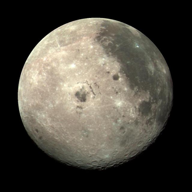
This color image of the Moon was taken by NASA's Galileo spacecraft at 9:35 a.m. PST Dec. 9, 1990, at a range of about 350,000 miles. The concentric, circular Orientale basin, is near the center; the nearside is to the right, the far side to the left. http://photojournal.jpl.nasa.gov/catalog/PIA00113
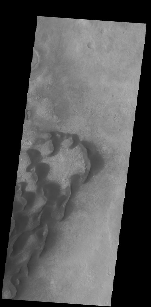
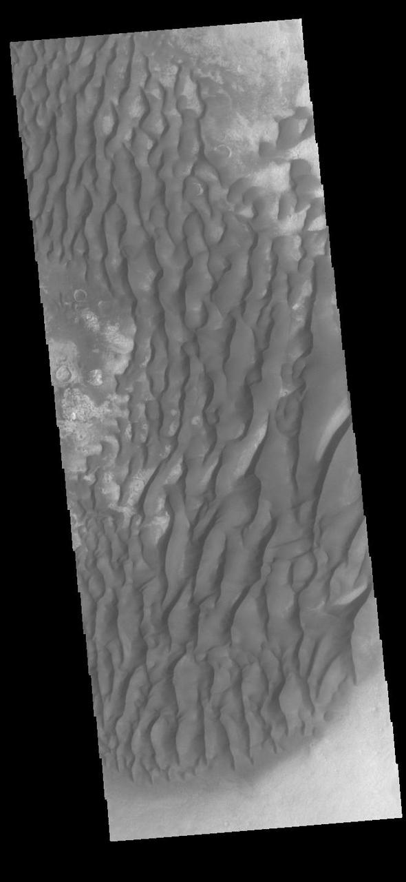
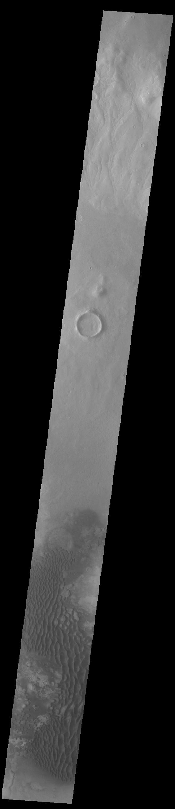
This VIS image is located in Kaiser Crater and shows several individual dunes. With continued winds sand dunes will move across the surface. There are two sides to a dune, the low angle slope of the windward face and the high angle slope of the leeward side. The steep side is called the slip face. Wind blows sand grains up the low angle slope of the dunes which then "fall down" the slip face. In this way the whole dune moves towards the slip face. The winds blow from the windward to the leeward side of the dunes. In this image the slip faces are on the left side of the dune, so the dunes are slowly moving to the left side of this image. Orbit Number: 75451 Latitude: -46.7049 Longitude: 20.0962 Instrument: VIS Captured: 2018-12-17 21:20 https://photojournal.jpl.nasa.gov/catalog/PIA23036
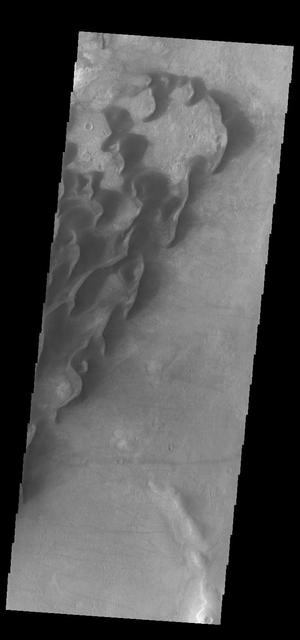
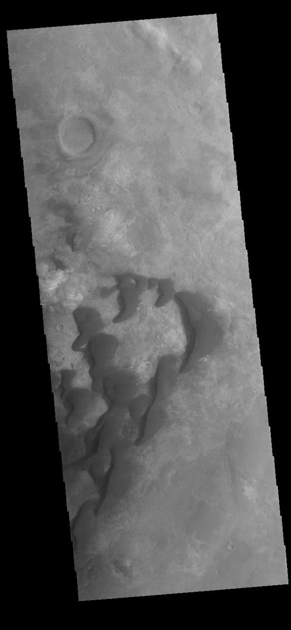
This VIS image is located in Kaiser Crater and shows many individual dunes. The crater floor is visible between the dunes, indicating that there is a limited sand supply creating the dunes. Local winds continue to move the sand dunes across the crater floor. There are two sides to a dune, the low angle slope of the windward face and the high angle slope of the leeward side. The steep side is called the slip face. Wind blows sand grains up the low angle slope of the dunes which then "fall down" the slip face. In this way the whole dune moves towards the slip face. The winds blow from the windward to the leeward side of the dunes. In this image the slip faces are on the left side of the dune, so the dunes are slowly moving to the left side of this image. Kaiser Crater is located in Noachis Terra. Orbit Number: 84872 Latitude: -47.0102 Longitude: 20.0034 Instrument: VIS Captured: 2021-01-31 15:23 https://photojournal.jpl.nasa.gov/catalog/PIA24735
This VIS image is located in Kaiser Crater and shows many individual dunes. The crater floor is visible between some of the dunes, indicating that there is a limited sand supply creating the dunes. Local winds continue to move the sand dunes across the crater floor. There are two sides to a dune, the low angle slope of the windward face and the high angle slope of the leeward side. The steep side is called the slip face. Wind blows sand grains up the low angle slope of the dunes which then "fall down" the slip face. In this way the whole dune moves towards the slip face. The winds blow from the windward to the leeward side of the dunes. In this image the slip faces are on the left side of the dune, so the dunes are slowly moving to the left side of this image. Kaiser Crater is located in Noachis Terra. Orbit Number: 91442 Latitude: -46.9786 Longitude: 19.5191 Instrument: VIS Captured: 2022-07-26 15:07 https://photojournal.jpl.nasa.gov/catalog/PIA25571
This VIS image is located in Kaiser Crater and shows many individual dunes. The crater floor is visible between the dunes, indicating that there is a limited sand supply creating the dunes. Local winds continue to move the sand dunes across the crater floor. There are two sides to a dune, the low angle slope of the windward face and the high angle slope of the leeward side. The steep side is called the slip face. Wind blows sand grains up the low angle slope of the dunes which then "fall down" the slip face. In this way the whole dune moves towards the slip face. The winds blow from the windward to the leeward side of the dunes. In this image the slip faces are on the left side of the dune, so the dunes are slowly moving to the left side of this image. Kaiser Crater is located in Noachis Terra. Orbit Number: 89982 Latitude: -46.6859 Longitude: 20.0452 Instrument: VIS Captured: 2022-03-28 09:55 https://photojournal.jpl.nasa.gov/catalog/PIA25467
This VIS image is located in Kaiser Crater and shows many individual dunes. The crater floor is visible between the dunes, indicating that there is a limited sand supply creating the dunes. Local winds continue to move the sand dunes across the crater floor. There are two sides to a dune, the low angle slope of the windward face and the high angle slope of the leeward side. The steep side is called the slip face. Wind blows sand grains up the low angle slope of the dunes which then "fall down" the slip face. In this way the whole dune moves towards the slip face. The winds blow from the windward to the leeward side of the dunes. In this image the slip faces are on the left side of the dune, so the dunes are slowly moving to the left side of this image. Kaiser Crater is located in Noachis Terra. Orbit Number: 83387 Latitude: -46.8031 Longitude: 19.7369 Instrument: VIS Captured: 2020-10-01 08:54 https://photojournal.jpl.nasa.gov/catalog/PIA24256
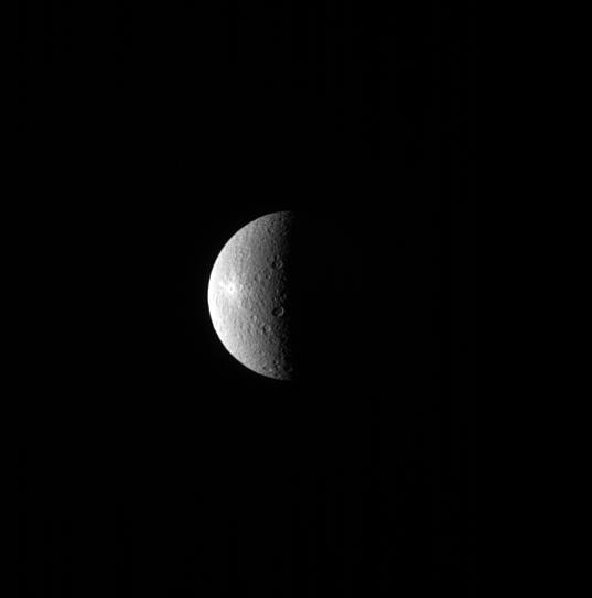
A bright spot can be seen on the left side of Rhea in this image. The spot is the crater Inktomi, named for a Lakota spider spirit. Inktomi is believed to be the youngest feature on Rhea (949 miles or 1527 kilometers across). The relative youth of the feature is evident by its brightness. Material that is newly excavated from below the moon's surface and tossed across the surface by a cratering event, appears bright. But as the newly exposed surface is subjected to the harsh space environment, it darkens. This is one technique scientists use to date features on surfaces. This view looks toward the trailing hemisphere of Rhea. North on Rhea is up and rotated 21 degrees to the left. The image was taken in visible light with the Cassini spacecraft narrow-angle camera on July 29, 2013. The view was obtained at a distance of approximately 1.0 million miles (1.6 million kilometers) fro http://photojournal.jpl.nasa.gov/catalog/PIA18300
This unnamed northern crater contains several dune fields. Within the central peak region (left side of image) there is material with a "swirled" surface pattern/texture. This type of texture indicates that volitiles may exist within the material. Image information: VIS instrument. Latitude 41.8N, Longitude 44.8E. 38 meter/pixel resolution. http://photojournal.jpl.nasa.gov/catalog/PIA09124
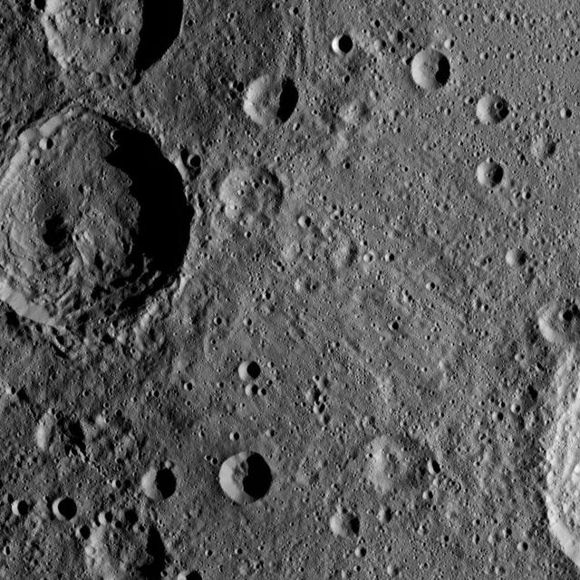
Sintana Crater is seen on the left side of this image of Ceres from NASA's Dawn spacercraft. The crater's central peak casts a shadow over its western flank. At lower right, the rim of Darzamat peeks into view. Dawn took this image on Oct. 19 from its second extended-mission science orbit (XMO2), at a distance of about 920 miles (1,480 kilometers) above the surface. The image resolution is about 460 feet (140 meters) per pixel. http://photojournal.jpl.nasa.gov/catalog/PIA21234
The left side of this 360-degree panorama from NASA's Curiosity Mars rover shows the long rows of ripples on a linear shaped dune in the Bagnold Dune Field on the northwestern flank of Mount Sharp. The view is a mosaic of images taken with Curiosity's Navigation Camera (Navcam) on Feb. 5, 2017, during the 1,601st Martian day, or sol, of the rover's work on Mars. The view is centered toward west-southwest, with east-southeast on either end. A capped mound called "Ireson Hill" is on the right. http://photojournal.jpl.nasa.gov/catalog/PIA21268
art002e009057 (April 4, 2026) - A view of the nearside of the Moon, the side we always see from Earth. Some of the far side is visible, as well, on the left edge, just beyond the black patch that is Orientale basin, a nearly 600-mile-wide crater that straddles the Moon’s near and far sides and is partly visible from Earth. The dark areas in the center and right side of the disk are ancient lava flows, which are unique to the near side of the Moon. The white dot at the bottom of the disk, with white rays shooting out from it, is Tycho crater, one of the younger craters on the Moon at 108 million years old.
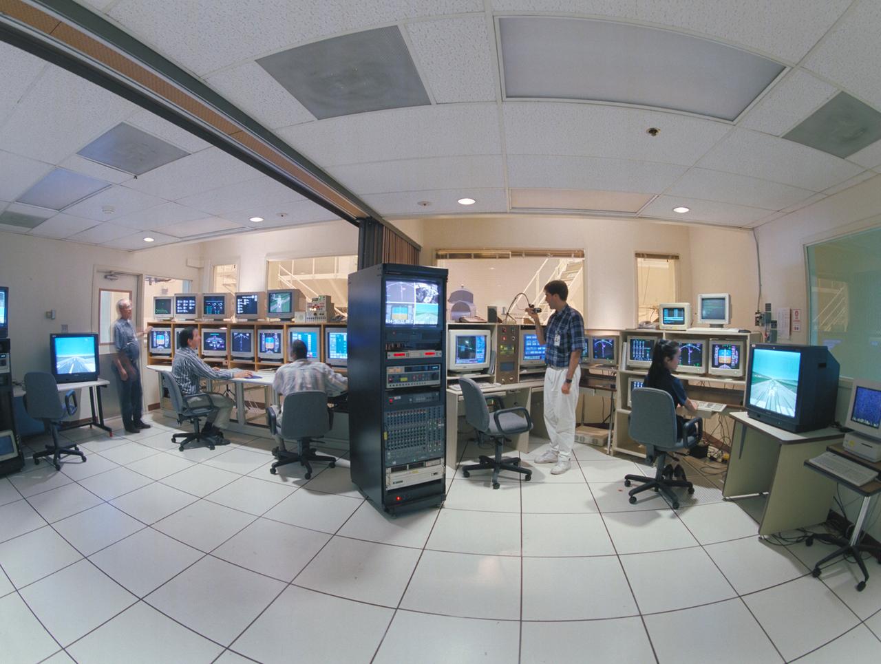
N-257 CVSRF: control rooms for 747 and ACSF cabs - LEFT SIDE; EOS - ACFS (Advanced Cab Flight Simulator) w. (l-r) Victor Loesche, Hector Reyes & Eric Jacobs and RIGHT SIDE; EOS - 747 Cab with (l-r) David Brown and Cindy Nguyen
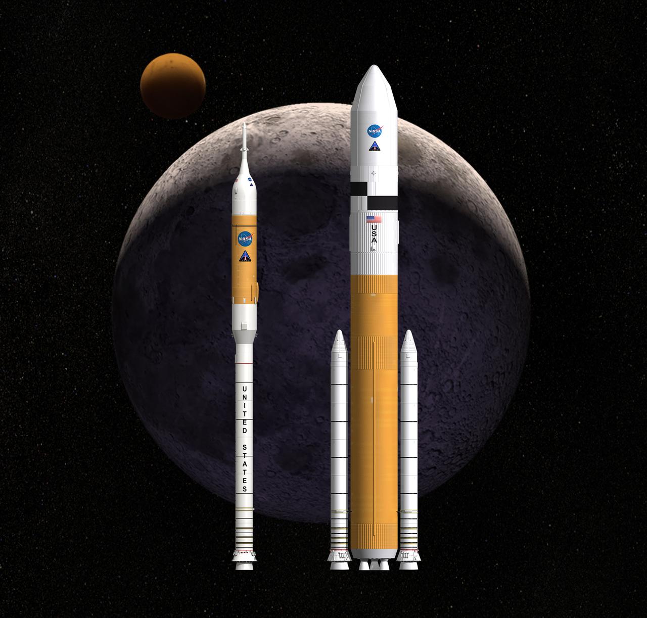
THIS CONCEPT IMAGE SHOWS NASA'S NEXT GENERATION LAUNCH VEHICLE SYSTEMS STANDING SIDE BY SIDE. ARES I, LEFT, IS THE CREW LAUNCH VEHICLE THAT WILL CARRY THE ORION CREW EXPLORATION VEHICLE TO SPACE. ARES V IS THE CARGO LAUNCH VEHICLE THAT WILL DELIVER LARGE SCALE HARDWARE, INCLUDING THE LUNAR LANDER, TO SPACE.
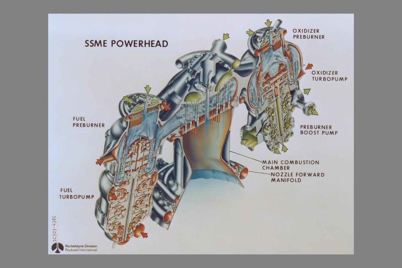
cutaway Rockwell International Space Shuttle Main Engines: Powerhead (Left side - fuel preburner, fuel trubopump - Center - Main Combustion Chamber, nozzle forward manifold - Right side - oxidizer preburner, oxidizer turbopump, preburner boost pump)
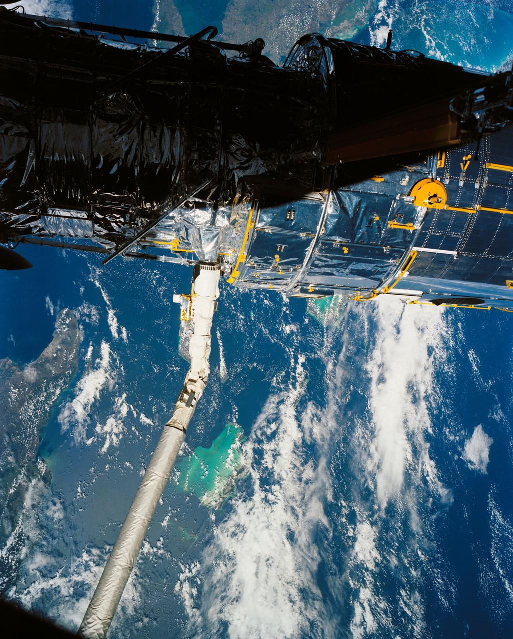
A close up deploy view of the Hubble Space Telescope on the end of the space shuttle remote manipulator system (RMS) with Eastern Cuba, (20.0N, 74.0W) seen on the left side of the telescope and northern Haiti seen on the right side of the telescope. The light colored blue feature in the water north of Haiti is the shallow waters of the Caicos Bank.

Close up documentation of the Left Side Rudder Leading Edge becoming delaminated on T-38A, NASA 962, on Dec. 6, 1983.
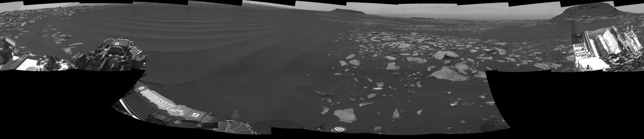
NASA's Curiosity Mars rover used its navigation cameras, or Navcams, to capture this panorama of the narrow "Paraitepuy Pass" on Aug. 11, 2022, the 3,560th Martian day, or sol, of the mission. The pass, with hills in the distance, can be seen on the left side of the scene. The hill in the center of this scene is "Bolívar"; "Deepdale" is on the far left of the scene. The crater floor is visible in the background of the right side of the panorama. https://photojournal.jpl.nasa.gov/catalog/PIA25417

KENNEDY SPACE CENTER, FLA. - On a tour of the Orbiter Processing Facility, Center Director Jim Kennedy (left) listens to Kathy Laufenberg, Orbiter Airframe Engineering ground area manager, with United Space Alliance, about corrosion work being done on the external tank door of orbiter Endeavour. On either side of Laufenberg are Tom Roberts, Airframe Engineering System specialist, also with USA, and Joy Huff, with KSC Space Shuttle Processing. Endeavour is in its Orbiter Major Modification period, which began in December 2003.
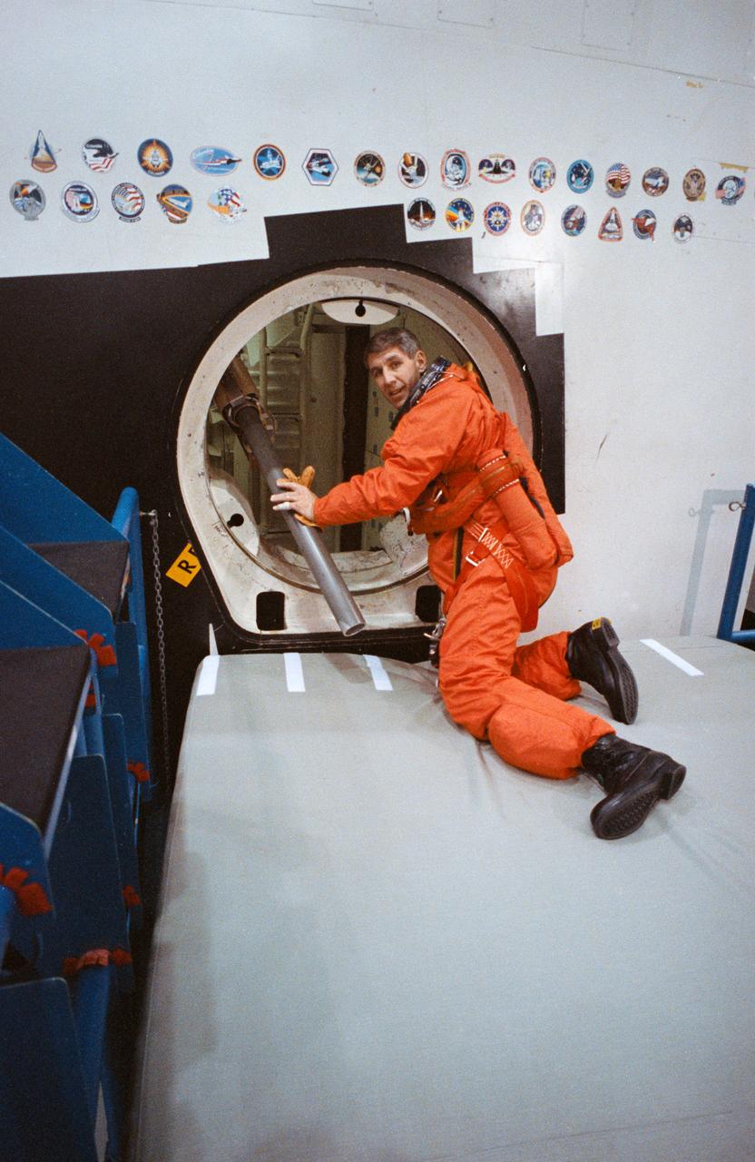
STS-38 Mission Specialist (MS) Robert C. Springer, wearing launch and entry suit (LES), climbs through the side hatch of the crew compartment trainer (CCT) located in JSC's Mockup and Integration Laboratory (MAIL) Bldg 9A. Springer will practice emergency egress through the side hatch using the crew escape system (CES) pole (at Springer's left). The inflated safety cushion under Springer will break his fall as he rolls out of the side hatch.

jsc2022e004237 (11/8/2021) --- A Preflight image of the Acoustics to Manipulate Fluids investigation, the acoustic tweezer apparatus is installed inside the Microgravity Science Glovebox Engineering Unit. The sample chamber, shown in the upper the right side, is where fluid droplets are injected via a septum located on the right side and manipulated by an ultrasonic transducer located on the left side. Image courtesy of Dr. Robert Lirette.
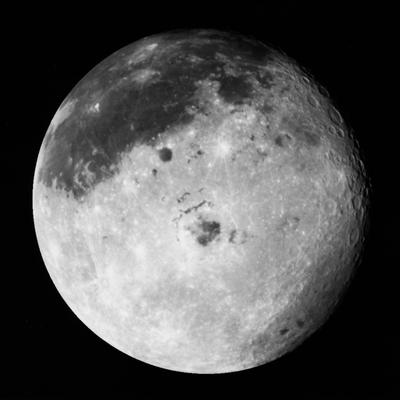
S90-55753 (9 Dec. 1990) --- This color image of the Moon was taken by the Galileo spacecraft at 9:25 a.m. (PST) December 9, 1990, at a range of about 350,000 miles. The color composite uses monochrome images taken through violet, red, and near infrared filters. The concentric, circular Orientale Basin, 600 miles across, is near the center; the near side is to the right, the far side to the left. At the upper right is the large, dark Oceanus Procellarum; below it is the smaller Mare Humorum. These, like the small dark Mare Orientale in the center of the basin, formed over 3 billion years ago as basaltic lava flows. At the lower left, among the southern cratered highlands of the far side, is the South-Pole-Aitken Basin, similar to Orientale but twice as great in diameter and much older and more degraded by crating and weathering. The cratered highlights of the near and far sides and the Maria are covered with scattered bright, young ray-craters.
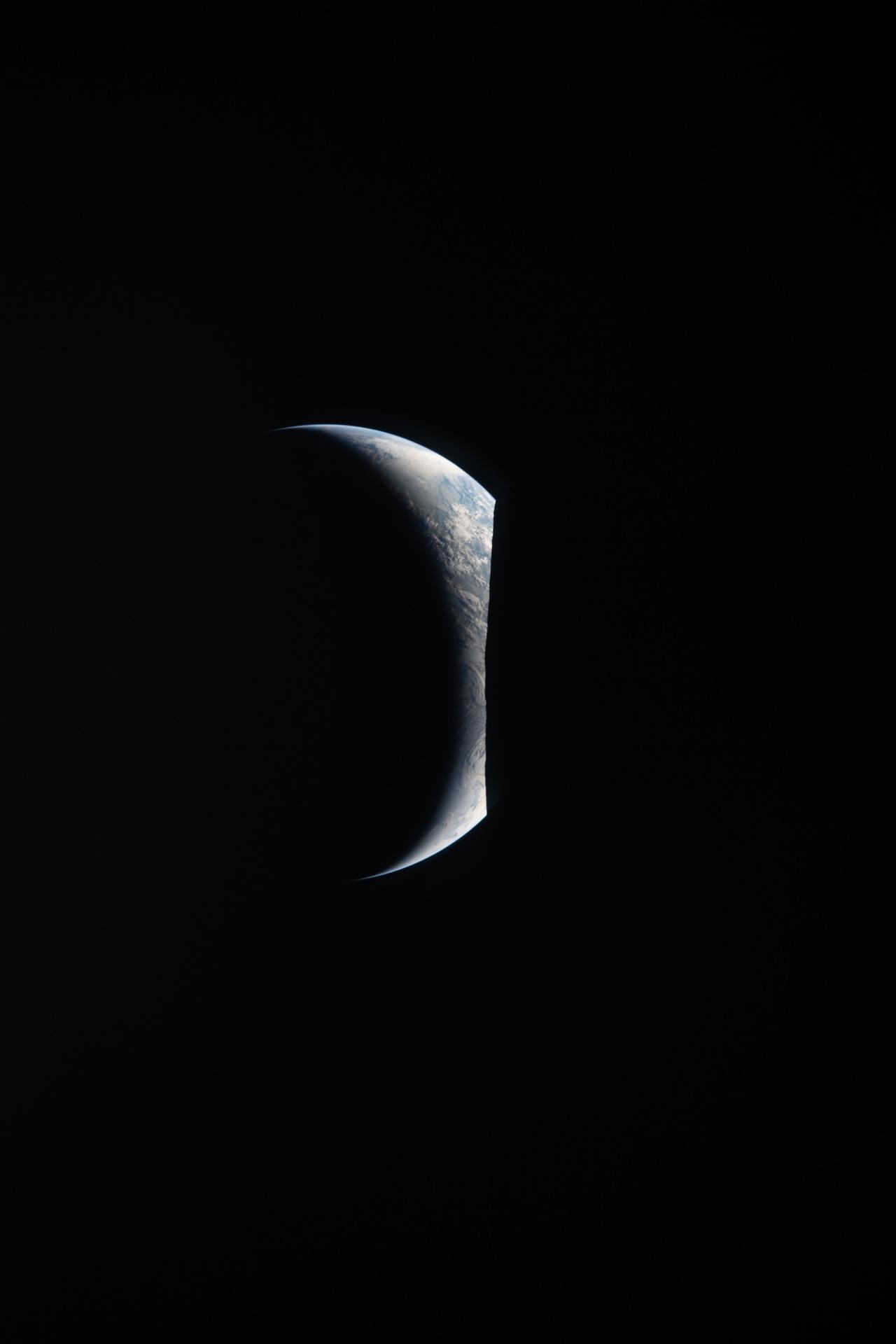
art002e009280 (April 6, 2026) – Earthrise captured through the Orion spacecraft window at 7:22 p.m. ET during the Artemis II crew’s flyby of the Moon’s far side. Earth appears as a delicate crescent, with only its left edge illuminated. The planet’s soft blue hue and scattered white cloud systems stand out on the right against the blackness of space, while the left side fades into night. Taken with a 400 mm lens, the image, Earthrise, reveals a striking alignment of Earth and Moon. In the foreground on the right, a portion of the Moon in night is barely visible save for its edge, which stands out in stark contrast against the illuminated side of Earth on the left. Along the Moon’s edge, rugged terrain is silhouetted against the bright crescent Earth. This photo was rotated 90 degrees clockwise for standard viewing orientation.
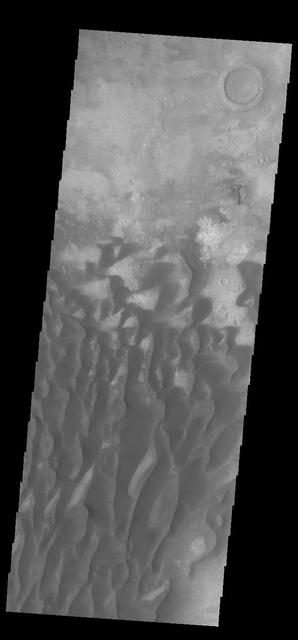
This VIS image is located in Kaiser Crater and shows a dune field on the crater floor. The crater floor is visible between the dunes, indicating that there is a limited sand supply creating the dunes. Local winds continue to move the sand dunes across the crater floor. There are two sides to a dune, the low angle slope of the windward face and the high angle slope of the leeward side. The steep side is called the slip face. Wind blows sand grains up the low angle slope of the dunes which then "fall down" the slip face. In this way the whole dune moves towards the slip face. The winds blow from the windward to the leeward side of the dunes. In this image the slip faces are on the left side of the dune, so the dunes are slowly moving to the left side of this image. Kaiser Crater is 207 km (129 miles) in diameter and is located in Noachis Terra west of Hellas Planitia. Orbit Number: 84585 Latitude: -45.8116 Longitude: 19.5816 Instrument: VIS Captured: 2021-01-08 00:14 https://photojournal.jpl.nasa.gov/catalog/PIA24415

iss063e050071 (July 16, 2020) --- The International Space Station was orbiting above the Northern Territory of Australia when this photograph was taken of the Gulf of Carpentaria including (from bottom left to right) the Pellew Islands, Wellesley Islands and South Wellesley Islands. One of the station's main solar arrays drapes the left side of this photograph.

ISS047e066509 (04/17/2016) --- Morning breaks for astronauts and cosmonauts aboard the International Space Station. SpaceX’s Dragon spacecraft sits on the left side of frame, attached to the Earth-facing port of the Harmony module.
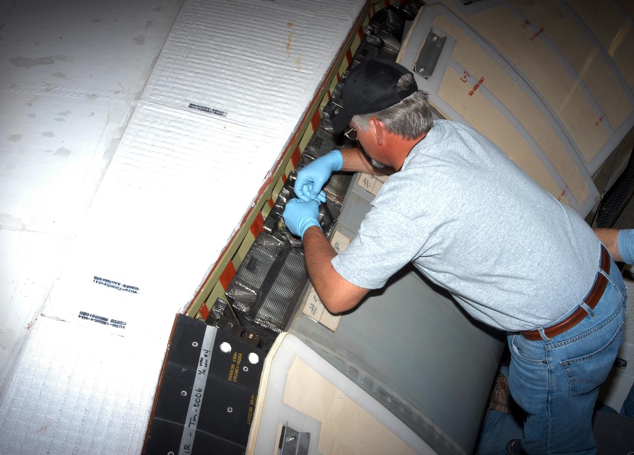
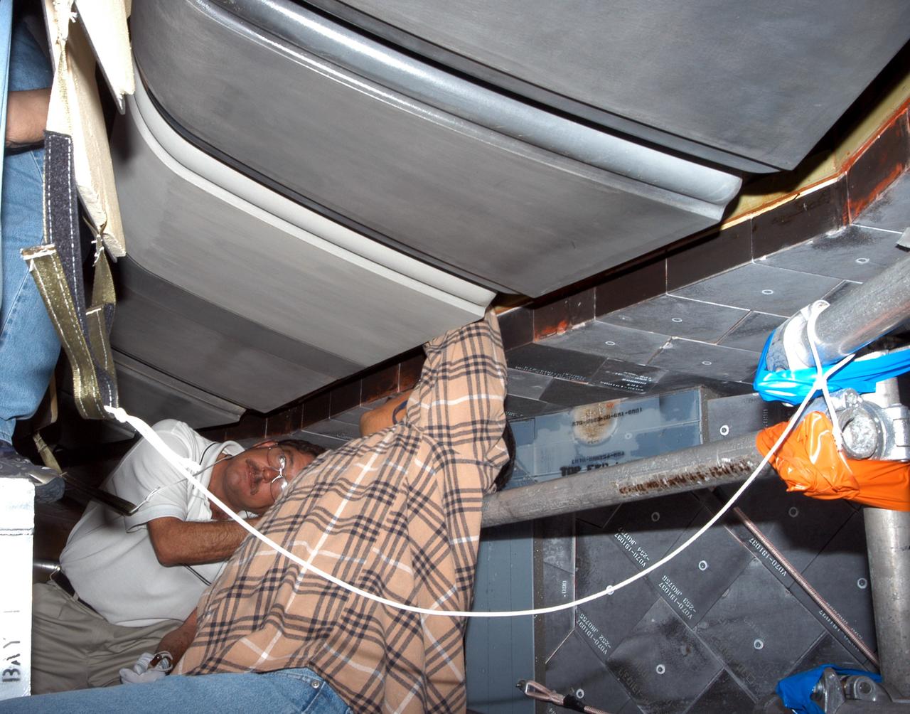
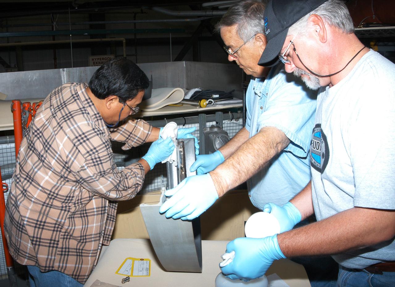
KENNEDY SPACE CENTER, FLA. - In the Orbiter Processing Facility, workers install C-shaped T-seals, which fit between each Reinforced Carbon Carbon panel, on the left-side wing leading edge of the orbiter Atlantis.
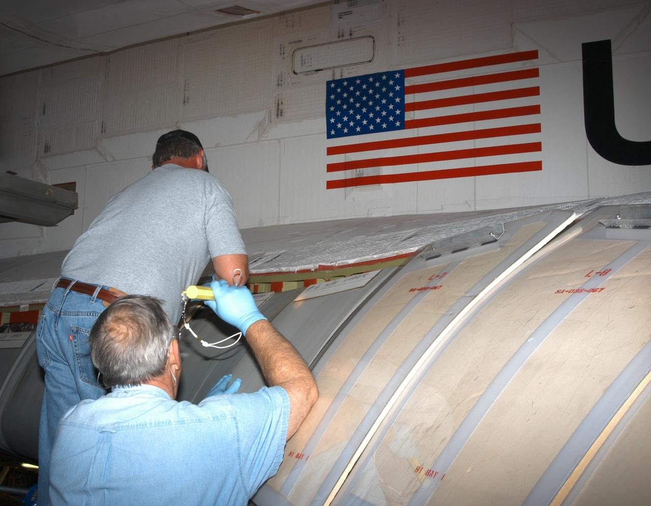
KENNEDY SPACE CENTER, FLA. - In the Orbiter Processing Facility, workers install C-shaped T-seals, which fit between each Reinforced Carbon Carbon panel, on the left-side wing leading edge of the orbiter Atlantis.
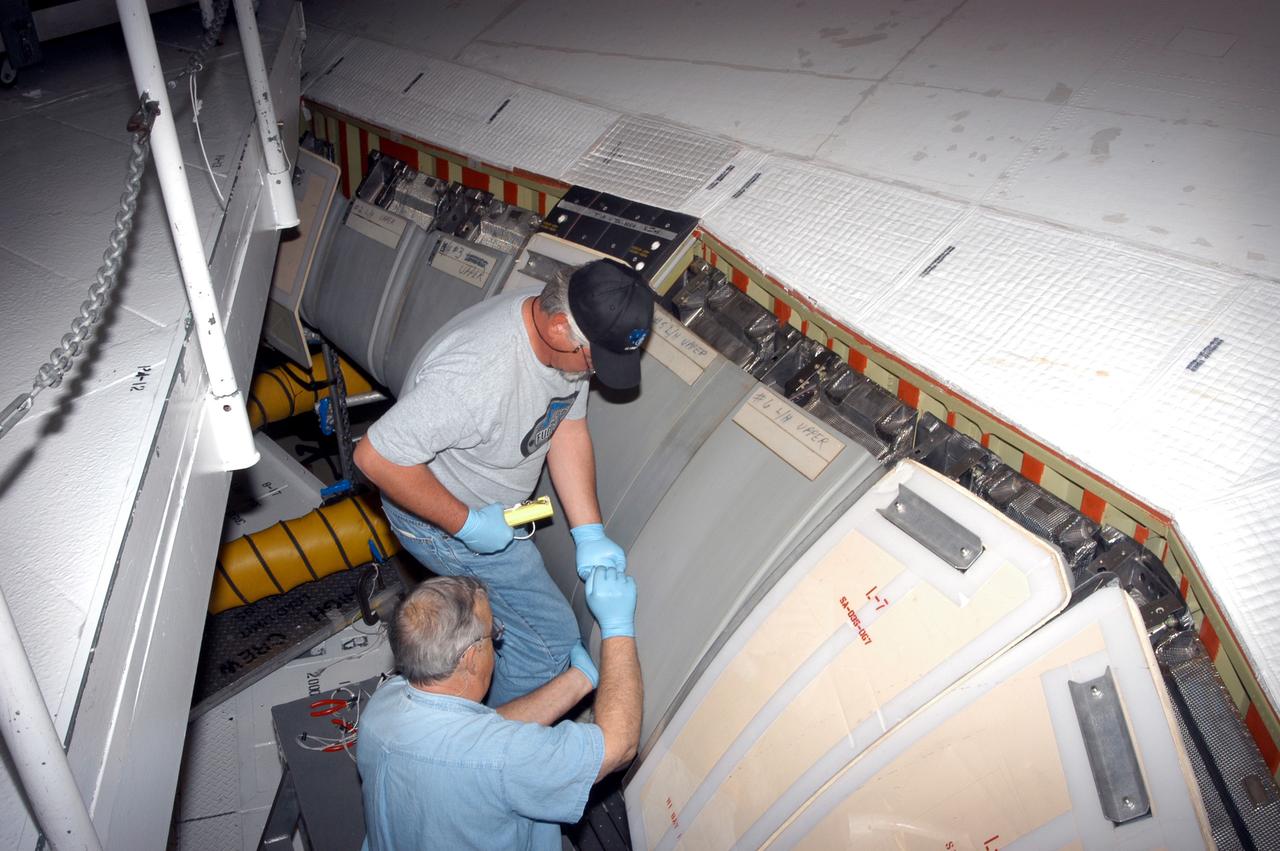
KENNEDY SPACE CENTER, FLA. - In the Orbiter Processing Facility, workers install C-shaped T-seals, which fit between each Reinforced Carbon Carbon panel, on the left-side wing leading edge of the orbiter Atlantis.
KENNEDY SPACE CENTER, FLA. - - In the Orbiter Processing Facility, workers install C-shaped T-seals, which fit between each Reinforced Carbon Carbon panel, on the left-side wing leading edge of the orbiter Atlantis.
KENNEDY SPACE CENTER, FLA. - In the Orbiter Processing Facility, workers install C-shaped T-seals, which fit between each Reinforced Carbon Carbon panel, on the left-side wing leading edge of the orbiter Atlantis.