
Doreen Zudell takes over as the Editor of the Lewis News, Center Newsletter
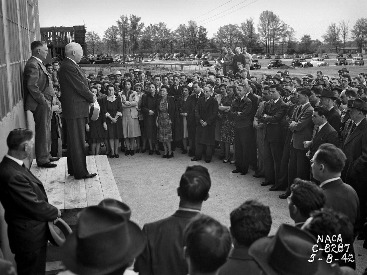
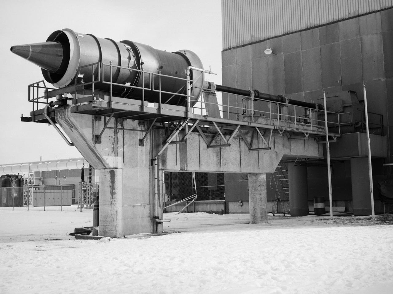
Construction Manager Raymond Sharp and the National Advisory Committee for Aeronautics (NACA) Director of Research George Lewis speak to employees during the May 8, 1942, Initiation of Research ceremony at the Aircraft Engine Research Laboratory. The event marked the first operation of a test facility at the new laboratory. The overall laboratory was still under construction, however, and behind schedule. Lewis traveled from his office in Washington, DC every week to personally assess the progress. Drastic measures were undertaken to accelerate the lab’s construction schedule. The military provided special supplies, contractors were given new agreements and pressured to meet deadlines, and Congress approved additional funds. The effort paid off and much of the laboratory was operational in early 1943. George Lewis managed the NACA’s aeronautical research for over 20 years. Lewis joined the NACA as Executive Officer in 1919, and was named Director of Aeronautical Research in 1924. In this role Lewis served as the liaison between the Executive Committee and the research laboratories. His most important accomplishment may have been the investigative tours of the research facilities in Germany in 1936 and 1939. The visits resulted in the NACA’s physical expansion and the broadening of the scope of its research. Lewis did not take a day of leave between the Pearl Harbor attack and the Armistice. He began suffering health problems in 1945 and was forced to retire two years later. The Aircraft Engine Research Laboratory was renamed the NACA Lewis Flight Propulsion Laboratory in September 1948.
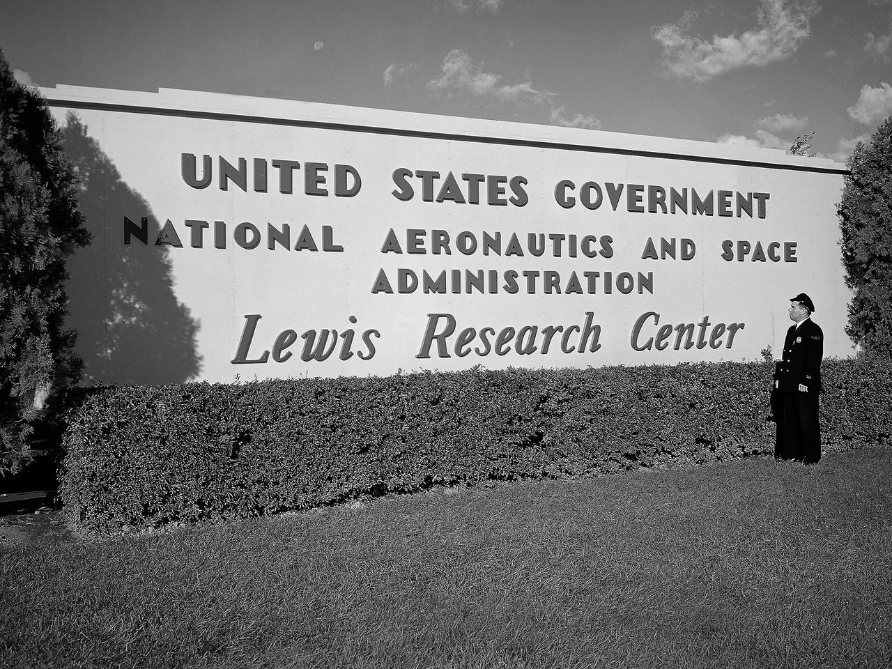
A security guard examines the new sign near the entrance to the Lewis Research Center one day after the National Aeronautics and Space Administration (NASA) was officially established. NASA came into being on October 1, 1958, and the National Advisory Committee for Aeronautics (NACA) Lewis Flight Propulsion Laboratory became the NASA Lewis Research Center. Lewis underwent a major reorganization and began concentrating its efforts almost exclusively on the space program. NACA Lewis researchers had been advocating further space research for years. As early as 1955, Lewis management urged the NACA expand its rocket engine research as a logical extension of its aircraft engine work. Lewis management claimed that space exploration was imperative for the nation’s survival during the Cold War. They called for an annual 25-percent increase in the NACA’s staff, a new space laboratory, a launching center, communications center, and other facilities. They were basically outlining what would be needed for the new space agency. During NASA’s first two years of existence, Lewis refocused its efforts almost completely on the space program. Less than 10 percent of the annual budget was dedicated to aeronautics. In the aftermath that followed President Kennedy’s April 1961 “Urgent Needs” address to Congress, NASA was given a seemingly unlimited budget. The Agency reorganized and began swelling its ranks through a massive recruiting effort to accomplish the accelerated lunar landing mission. Lewis personnel increased from approximately 2,700 in 1961 to over 4,800 in 1966.

The sign near the entrance of the National Advisory Committee for Aeronautics (NACA) Flight Propulsion Research Laboratory. The name was changed several weeks later to the Lewis Flight Propulsion Laboratory in honor of the NACA’s former Director of Aeronautical Research, George W. Lewis. The research laboratory has had five different names since its inception in 1941. The Cleveland laboratory was originally known as the NACA Aircraft Engine Research Laboratory. In 1947 it was renamed the NACA Flight Propulsion Research Laboratory to reflect the expansion of the research activities beyond just engines. Following the death of George Lewis, the name was changed to the NACA Lewis Flight Propulsion Laboratory in September 1948. On October 1, 1958, the lab was incorporated into the new NASA space agency, and it was renamed the NASA Lewis Research Center. Following John Glenn’s flight on the space shuttle, the name was changed again to the NASA Glenn Research Center on March 1, 1999. From his office in Washington DC, George Lewis managed the aeronautical research conducted at the NACA for over 20 years. His most important accomplishment, however, may have been an investigative tour of German research facilities in the fall of 1936. The visit resulted in the broadening of the scope of the NACA’s research and the physical expansion that included the new engine laboratory in Cleveland.
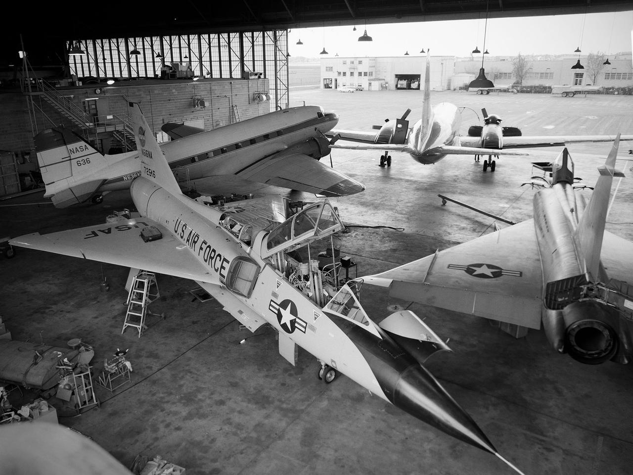
Several aircraft parked inside the Flight Research Building, or hangar, at the National Aeronautics and Space Administration (NASA) Lewis Research Center in Cleveland, Ohio. A Convair F-106B Delta Dart is in the foreground, a Convair F-102A Delta Dagger is to the right, a Douglas DC-3 is in the back to left, and a Convair T-29 is in background. Lewis’ Martin B-57B Canberra is not seen in this photograph. The F-102A had just been acquired by Lewis to serve as a chase plane for the F-106B. The Lewis team removed the weapons system and 700 pounds of wire from the F-106B when it was acquired on October 20, 1966. The staff cut holes in the wings and modified the elevons to mount the test nacelles. A 228-gallon fuel tank was installed in the missile bay, and the existing wing tanks were used for instrumentation. This photograph contains a rare view of the Block House, seen to the left of the aircraft. Lewis acquired three large developmental programs in 1962—the Centaur and Agena rockets and the M-1 engine. The center was short on office space at the time, and its flight research program was temporarily on the wane. Lewis management decided to construct a large cinderblock structure inside one half of the hangar to house the new personnel. This structure was used until 1965 when the new Developmental Engineering Building was built. The Block House was eventually torn down in 1973.
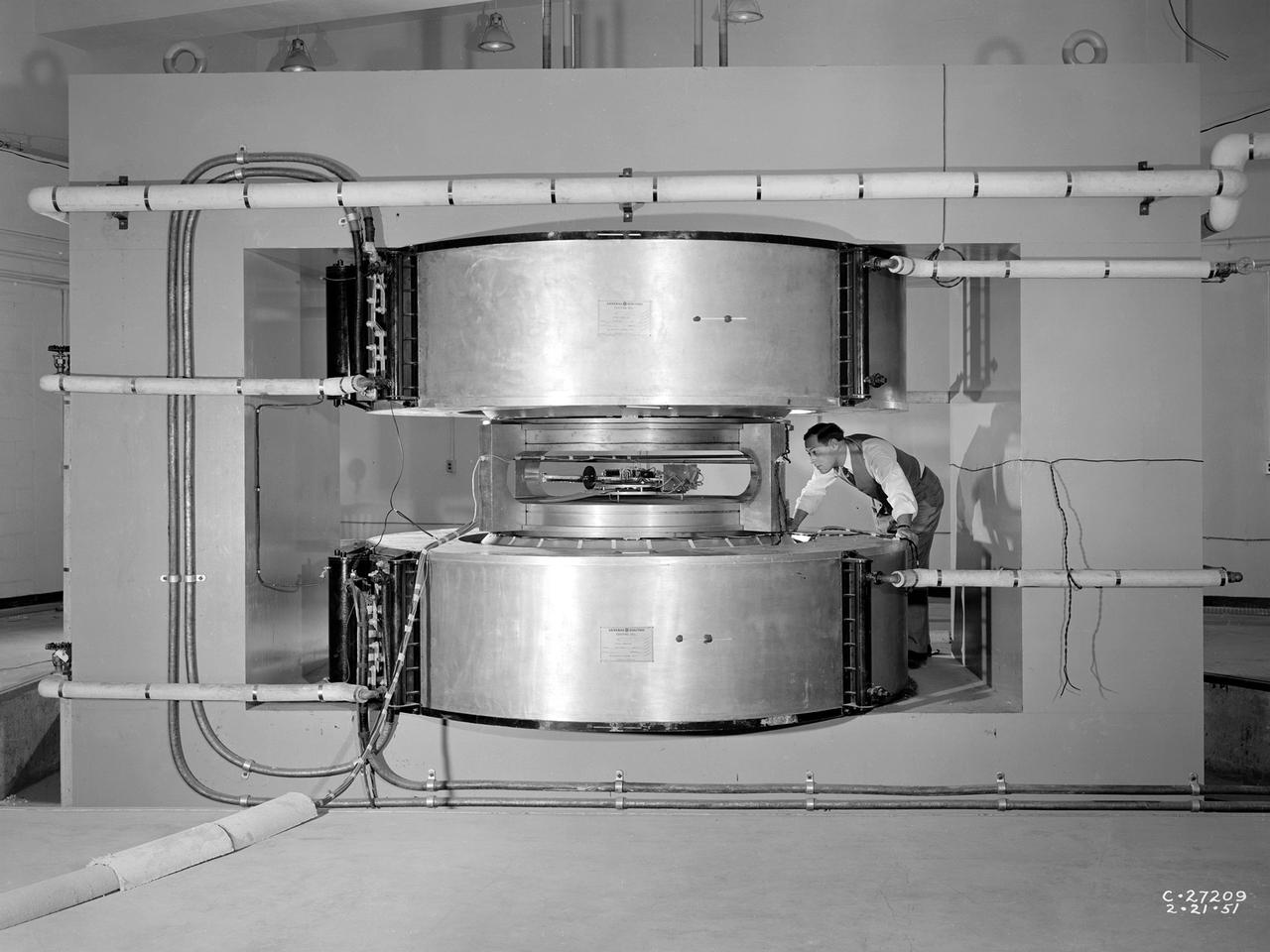
Researcher James Blue examines the new cyclotron at the National Advisory Committee for Aeronautics (NACA) Lewis Flight Propulsion Laboratory. Researchers at NACA Lewis began postulating about the use of atomic power for propulsion immediately after World War II. The NACA concentrated its efforts on the study of high temperature materials and heat transfer since it did not have access to the top secret fission information. The military studied the plausibility of nuclear propulsion for aircraft in the late 1940s. The military program was cancelled after four years without any breakthroughs, but the Atomic Energy Commission took on the effort in 1951. The NACA Lewis laboratory was expanding its nuclear-related research during this period. In 1948, Lewis engineers were assigned to the Oak Ridge National Laboratory to obtain expertise in high temperature heat transfer and advanced materials technology. The following year a new 80-person Nuclear Reactor Division was created, and an in-house nuclear school was established to train these researchers. The cyclotron was built behind the Materials and Structures Laboratory to support thermodynamic and materials research for both nuclear aircraft and nuclear rockets. The original NACA Lewis cyclotron was used to accelerate two kinds of particles. To better match the space radiation environment, the cyclotron was later modified to accelerate particles of the newly-discovered Van Allen radiation belts.
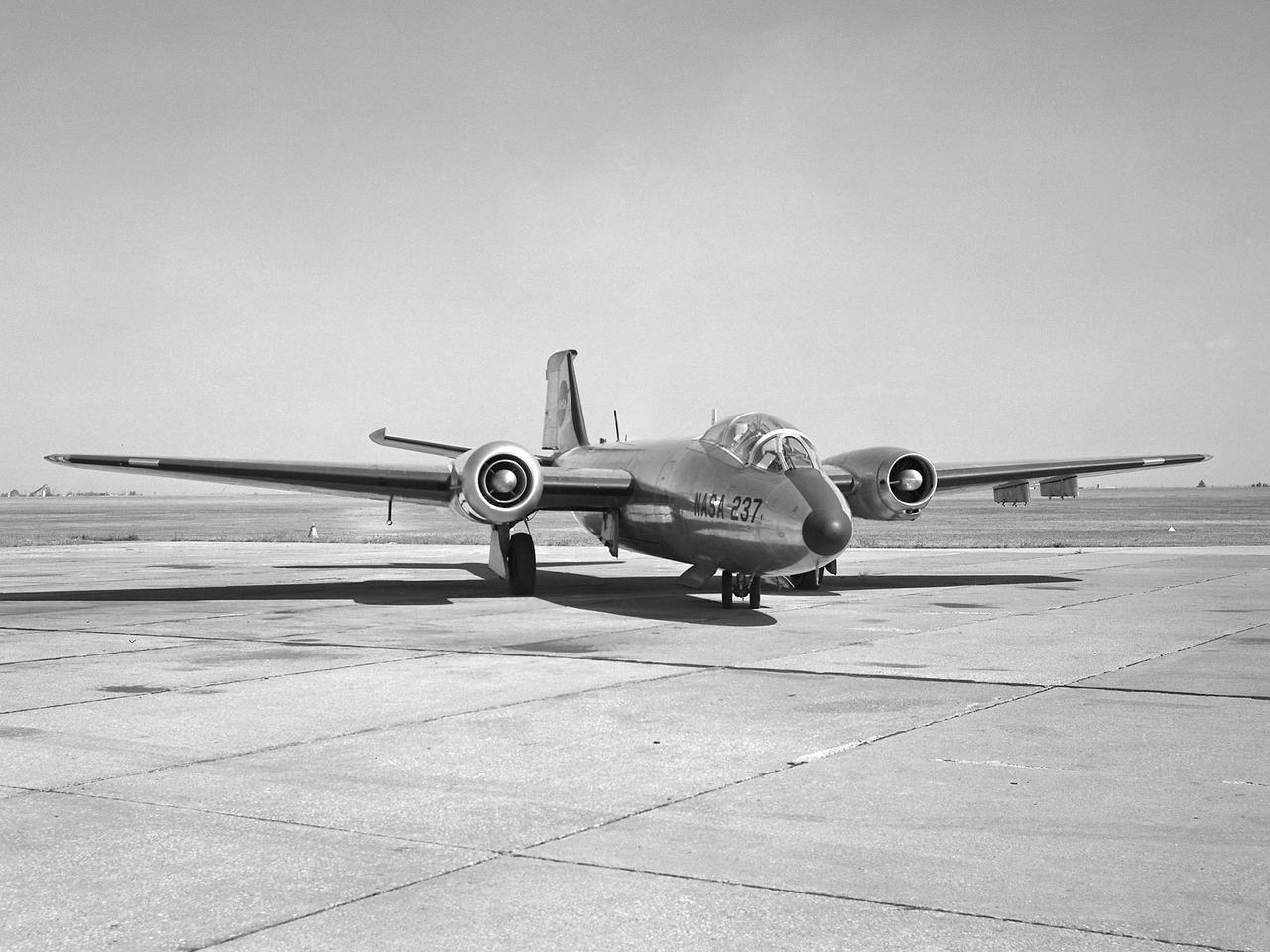
A Martin B-57B Canberra outfitted with a noise suppressor on its right engine at the National Aeronautics and Space Administration (NASA) Lewis Research Center. The aircraft was being prepared for the October 1966 Inspection of the center. The Inspection also marked Lewis’ twentieth anniversary. Lewis researchers had been studying engine noise for almost a decade, but the problem seemed to be increasing in the mid-1960s with heavier airline traffic and larger engines. Researchers discovered early on that the majority of the noise did not emanate from the engine itself, but from the mixing of the hot exhaust gasses with the atmosphere. Attempts to reduce the turbulence using new exhaust nozzles were successful but often resulted in decreased engine performance. The researchers decided to try to lower the jet nozzle exit velocity without decreasing its thrust. The inlet mass air flow had to be increased to accomplish this. The Lewis B-57B was powered by two Wright Aeronautical J65 turbojets. Lewis engineers modified the stators on the two engines to simulate the noise levels from more-modern turbofan engines. A noise suppressor was added to only one of the two engines, seen here on the left. The engines were run one at a time at power levels similar to landing while the aircraft sat on the Lewis hangar apron. A microphone and recording equipment was setup to capture the noise levels. The engine with the suppressor produced 13 fewer decibels than the standard engine.
Engineer Frank Kutina and a National Aeronautics and Space Administration (NASA) mechanic examine the setup of an advanced combustor rig inside one of the test cells at the Lewis Research Center’s Four Burner Area in the Engine Research Building. Kutina, of the Research Operations Branch, served as go-between for the researchers and the mechanics. He helped develop the test configurations and get the hardware installed. At the time of this photograph, Lewis Center Director Abe Silverstein had just established the Airbreathing Engine Division to address the new propulsion of the 1960s. After nearly a decade of focusing almost exclusively on space, NASA Lewis began tackling issues relating to the new turbofan engine, noise reduction, energy efficiency, supersonic transport, and the never-ending quest for higher performance levels with smaller and more lightweight engines. The Airbreathing Engine Division’s Combustion Branch was dedicated to the study and mitigation of the high temperatures and pressures found in advanced combustor designs. These high temperatures and pressures could destroy engine components. The Lewis investigation included film cooling, diffuser flow, and jet mixing. Components were tested in smaller test cells, but a full-scale augmenting burner rig, seen here, was tested extensively in the Four Burner Area test cell.
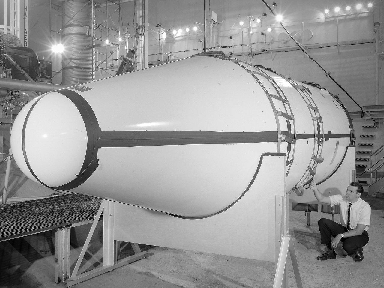
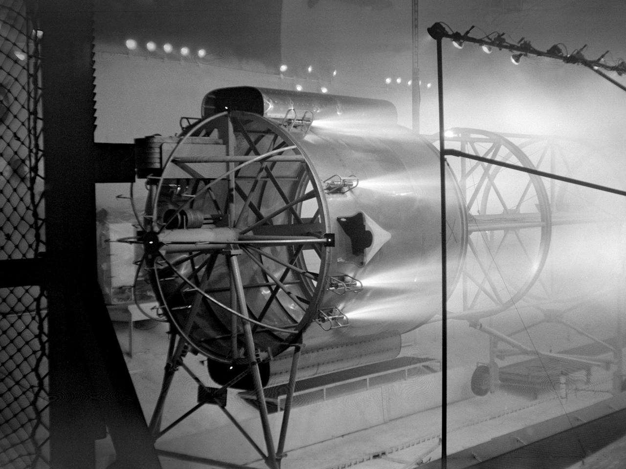
Setup of a Surveyor/Atlas/Centaur shroud in the Space Power Chambers for a leak test at the National Aeronautics and Space Administration (NASA) Lewis Research Center. Centaur was a 15,000-pound thrust second-stage rocket designed for the military in 1957 and 1958 by General Dynamics. It was the first major rocket to use the liquid hydrogen technology developed by Lewis in the 1950s. The Centaur Program suffered numerous problems before being transferred to Lewis in 1962. Several test facilities at Lewis’ main campus and Plum Brook Station were built or modified specifically for Centaur, including the Space Power Chambers. In 1961, NASA Lewis management decided to convert its Altitude Wind Tunnel into two large test chambers and later renamed it the Space Power Chambers. The conversion, which took over 2 years, included the removal of the tunnel’s internal components and insertion of bulkheads to seal off the new chambers. The larger chamber, seen here, could simulate altitudes of 100,000 feet. It was used for Centaur shroud separation and propellant management studies until the early 1970s. The leak test in this photograph was likely an attempt to verify that the shroud’s honeycomb shell did not seep any of its internal air when the chamber was evacuated to pressures similar to those found in the upper atmosphere.

The National Aeronautics and Space Administration (NASA) Lewis Research Center acquired this Gulfstream C-131B Samaritan from the Air Force in July 1976. The center obtained the aircraft to support its current earth resources work. The C-131B is seen here inside the Lewis hangar being refurbished and converted into a flying laboratory. The modifications were led by Lewis Chief of Flight Operations Robert Hogan. The cockpit and cabin were modified and packed with instrumentation. The new equipment included Sideways Looking Airborne Radar (SLAR), geothermal sensors, radar antennas, and an inertial navigation system. In addition, portals were installed underneath the fuselage for cameras and remote sensing equipment. NASA’s C-131B was used to support researchers tracking ice flows on the Great Lakes and in Prudhoe Bay, Alaska. It was also used for the center’s program to determine heating losses in the Cleveland area’s residential and commercial structures. The aircraft was later donated to the University of Georgia.
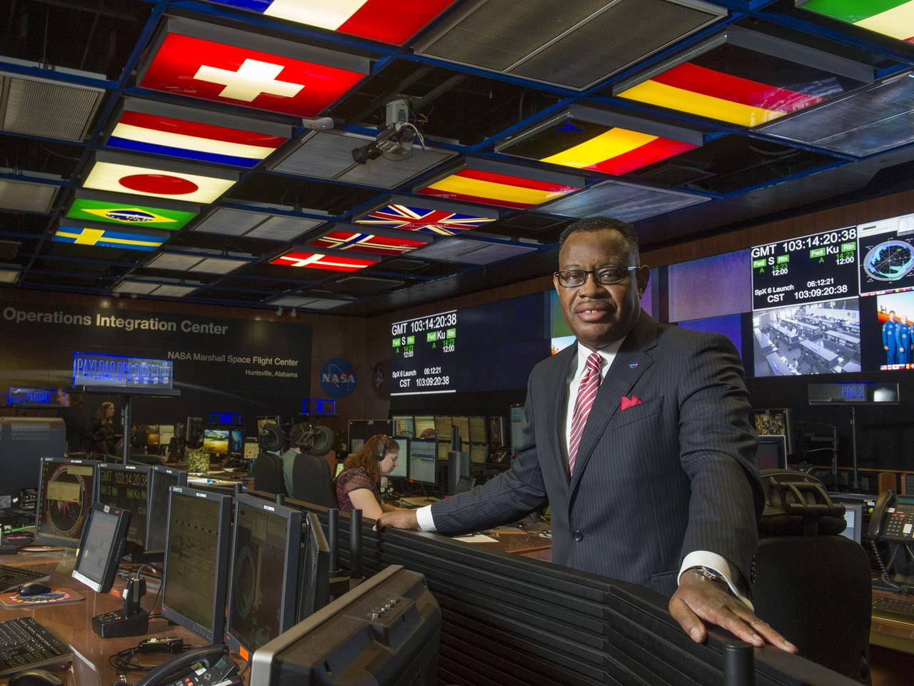
LEWIS WOOTEN, NEW DIRECTOR OF THE MISSION OPERATIONS LABORATORY AT NASA'S MARSHALL SPACE FLIGHT CENTER IN HUNTSVILLE, ALABAMA, MANAGES OPERATIONS IN THE PAYLOAD OPERATIONS INTEGRATION CENTER-THE COMMAND POST FOR ALL SCIENCE AND RESEARCH ACTIVITIES ON THE INTERNATIONAL SPACE STATION
Addison Rothrock, the National Advisory Committee for Aeronautics’s (NACA) Assistant Director of Research, speaks at the groundbreaking ceremony for the Lewis Flight Propulsion Laboratory’s new test reactor at Plum Brook Station. This dedication event was held almost exactly one year after the NACA announced that it would build its $4.5 million nuclear reactor on 500 acres of the army’s 9000-acre Plum Brook Ordnance Works. The site was located in Sandusky, Ohio, approximately 60 miles west of the NACA Lewis laboratory in Cleveland. Lewis Director Raymond Sharp is seated to the left of Rothrock, Congressman Albert Baumhart and NACA Secretary John Victory are to the right. Many government and local officials were on hand for the press conference and ensuing luncheon. In the wake of World War II the military, the Atomic Energy Commission, and the NACA became interested in the use of atomic energy for propulsion and power. A Nuclear Division was established at NACA Lewis in the early 1950s. The division’s request for a 60-megawatt research reactor was approved in 1955. The semi-remote Plum Brook location was selected over 17 other possible sites. Construction of the Plum Brook Reactor Facility lasted five years. By the time of its first trial runs in 1961 the aircraft nuclear propulsion program had been cancelled. The space age had arrived, however, and the reactor would be used to study materials for a nuclear powered rocket.
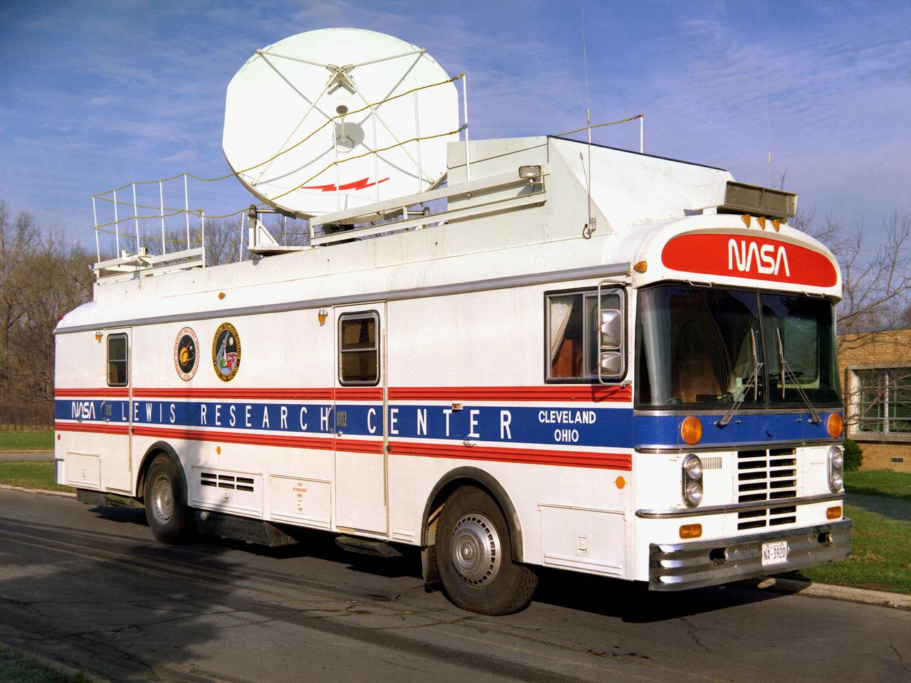
This vehicle served as a mobile terminal for the Communications Technology Satellite. The Communications Technology Satellite was an experimental communications satellite launched in January 1976 by the National Aeronautics and Space Administration (NASA) and the Canadian Department of Communications. The satellite operated in a new frequency band reserved for broadcast satellites with transmitting power levels that were 10 to 20 times higher than those of contemporary satellites. Throughout 1977 and 1978 NASA allowed qualified groups to utilize the satellite from one of the three ground-based transmission centers. NASA’s Lewis Research Center in Cleveland, Ohio was NASA’s lead center on the project. Lewis was responsible for the control and coordination of all US experiments on the satellite. The center housed the satellite’s main control center which included eight parabolic reflector antennae ranging from 2 to 15 feet in diameter. Many of the satellite’s components had been tested in simulated space conditions at Lewis. The Lewis-designed vehicle seen here served as a field unit for transmitting and receiving wideband signals and narrowband voice. The vehicle permitted live television interviews, recording equipment, and cameras. An 8-foot diameter parabolic reflector was mounted on the roof. The interior of the vehicle had workstations, monitors, transmitting equipment, and a lounge area.
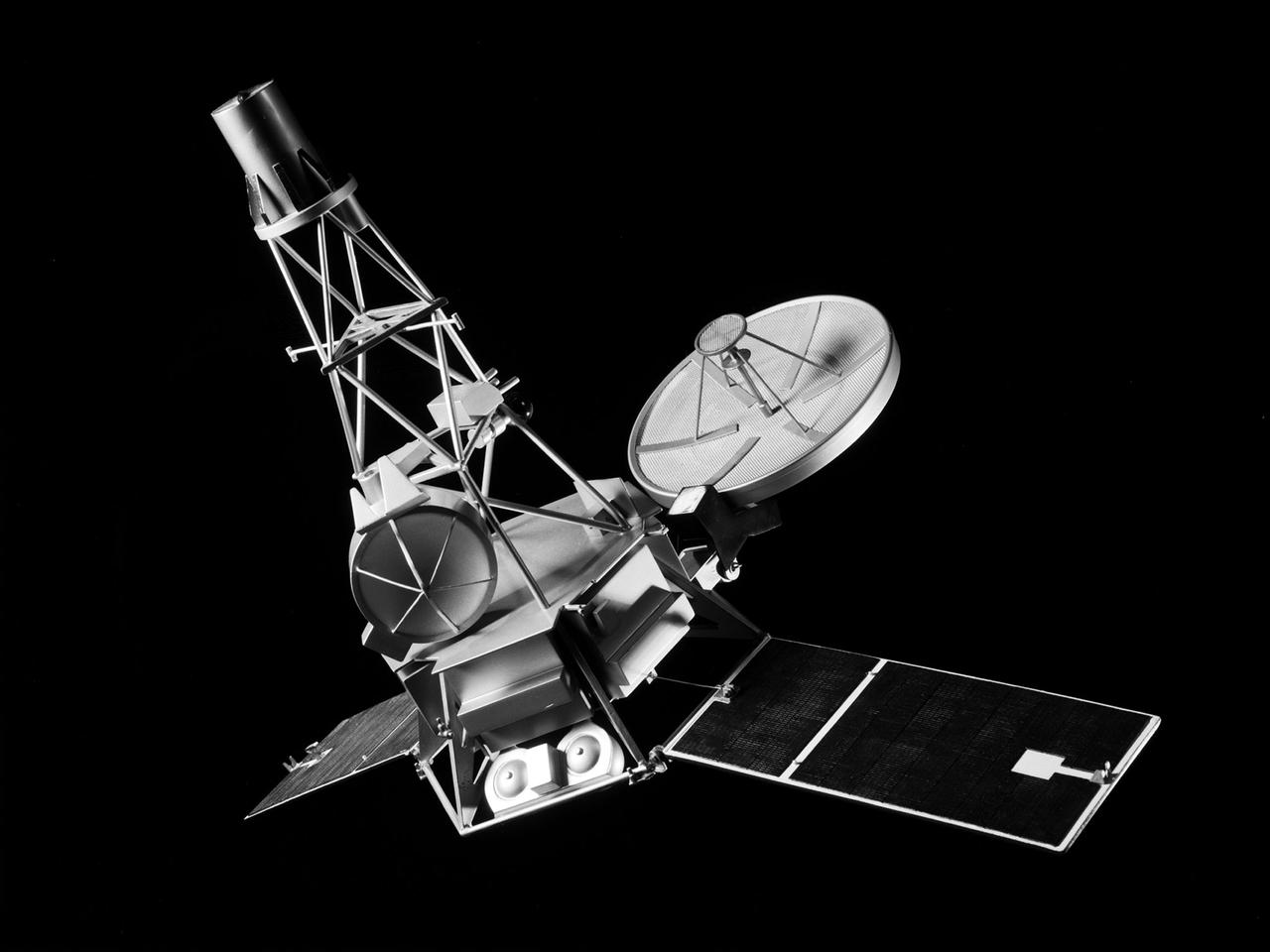
A model of the Mariner-C spacecraft at the National Aeronautics and Space Administration (NASA) Lewis Research Center for a June 1964 Conference on New Technology. Mariner-C and Mariner-D were identical spacecraft designed by the Jet Propulsion Laboratory to flyby Mars and photograph the Martian surface. Mariner-C was launched on November 4, 1964, but the payload shroud did not jettison properly and the spacecraft’s battery power did not function. The mission ended unsuccessfully two days later. Mariner-D was launched as designed on November 28, 1964 and became the first successful mission to Mars. It was the first time a planet was photographed from space. Mariner-D’s 21 photographs revealed an inhospitable and barren landscape. The two Mariner spacecraft were launched by Atlas-Agena-D rockets. Lewis had taken over management of the Agena Program in October 1962. There had been five failures and two partial failures in the 17 Agena launches before being taken over by NASA Lewis. Lewis, however, oversaw 28 successful Agena missions between 1962 and 1968, including several Rangers and the Mariner Venus '67.
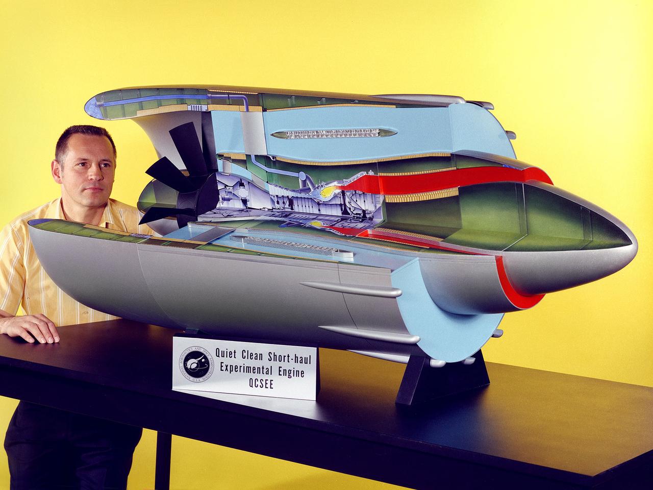
Program manager Carl Ciepluch poses with a model of the Quiet Clean Short Haul Experimental Engine (QCSEE) conceived by the National Aeronautics and Space Administration (NASA) Lewis Research Center. The QCSEE engine was designed to power future short-distance transport aircraft without generating significant levels of noise or pollution and without hindering performance. The engines were designed to be utilized on aircraft operating from small airports with short runways. Lewis researchers investigated two powered-lift designs and an array of new technologies to deal with the shorter runways. Lewis contracted General Electric to design the two QCSEE engines—one with over-the-wing power-lift and one with an under-the-wing design. A scale model of the over-the-wing engine was tested in the Full Scale Tunnel at the Langley Research Center in 1975 and 1976. Lewis researchers investigated both versions in a specially-designed test stand, the Engine Noise Test Facility, on the hangar apron. The QCSEE engines met the goals set out by the NASA researchers. The aircraft industry, however, never built the short-distance transport aircraft for which the engines were intended. Different technological elements of the engine, however, were applied to some future General Electric engines.
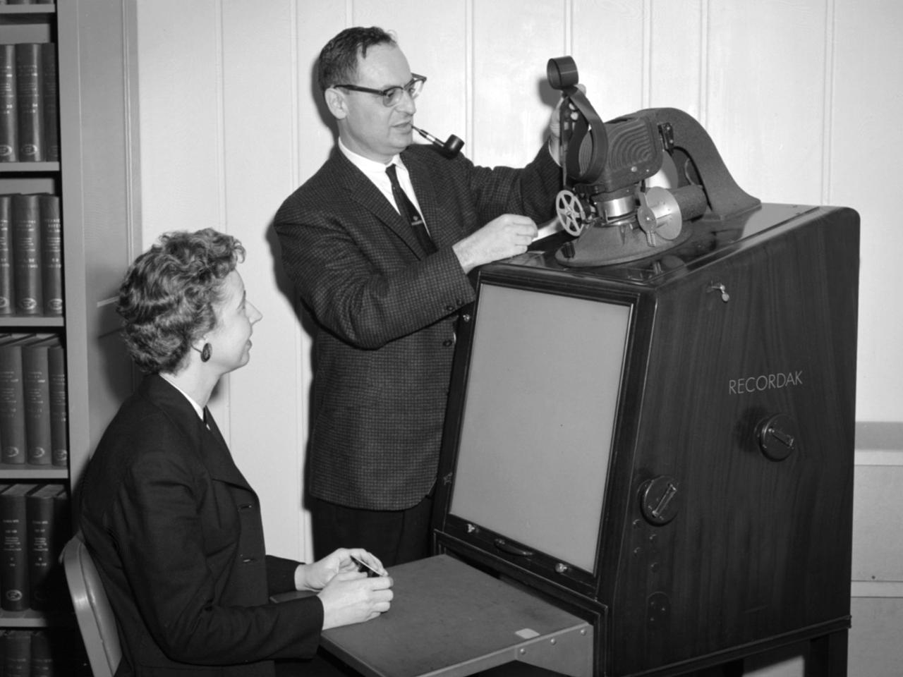
Jean Neidengard and George Mandel operate a Kodak Recordak microfilm reader in the library at the National Aeronautics and Space Administration (NASA) Lewis Research Center. The library was located in the Administration Building until the mid-1960s. It was then moved to the Propulsion Systems Laboratory Office Building. In 2008 the library was moved once again, to the Research Analysis Center. At the time of this photograph, the Lewis library claimed to possess “One of the most complete aero-technical collections in the world.” It was doing a brisk business in the early 1960s. During 1960 alone the library acquired 19,000 new documents and provided 100,000 documents to customers. The library’s eleven-person staff provided reference services, archived technical reports, and supplied periodicals. The staff also included Sam Reiss, a full-time translator who could read 30 languages. He translated technical reports from all over the world for the Lewis research staff. Jean Neidengard oversaw the secret Atomic Energy Commission (AEC) documents in the collection. NASA was partnering with the AEC at the time on Nuclear Engine for Rocket Vehicle Application (NERVA) program. NASA Lewis was the agency’s lead center in the NERVA program. Neidengard’s husband Bill was the head mechanic in the Propulsion Systems Laboratory. George Mandel led the library staff from 1955 to 1968.
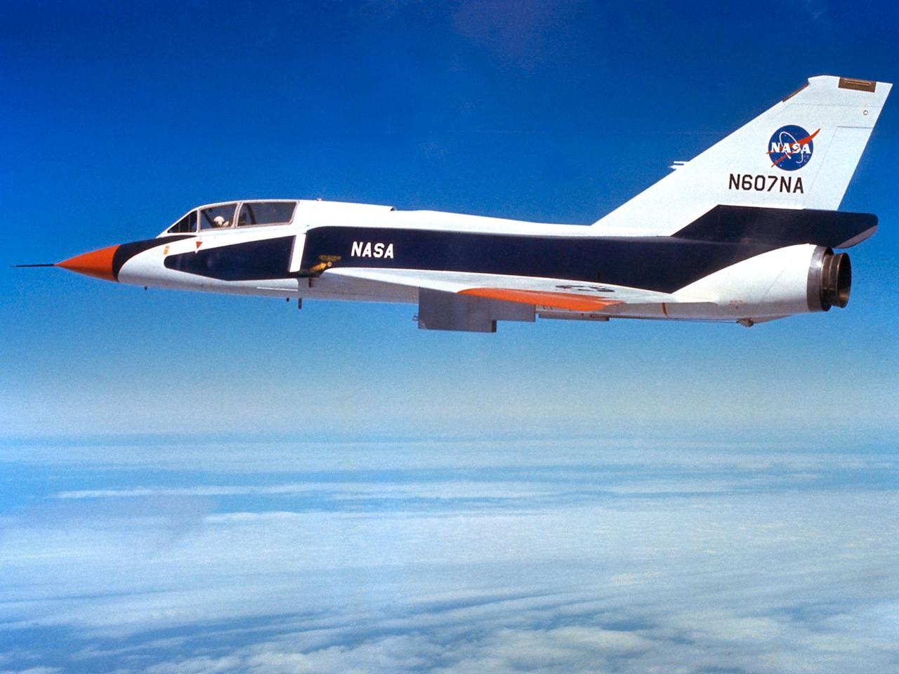
The National Aeronautics and Space Administration (NASA) Lewis Research Center’s Convair F-106B Delta Dart equipped with air sampling equipment in the mid-1970s. NASA Lewis created and managed the Global Air Sampling Program (GASP) in 1972 in partnership with several airline companies. NASA researchers used the airliners’ Boeing 747 aircraft to gather air samples to determine the amount of pollution present in the stratosphere. Private companies developed the air sampling equipment for the GASP program, and Lewis created a particle collector. The collector was flight tested on NASA Lewis’ F-106B in the summer of 1973. The sampling equipment was automatically operated once the proper altitude was achieved. The sampling instruments collected dust particles in the air so their chemical composition could be analyzed. The equipment analyzed one second’s worth of data at a time. The researchers also monitored carbon monoxide, monozide, ozone, and water vapor. The 747 flights began in December 1974 and soon included four airlines flying routes all over the globe. The F-106B augmented the airline data with sampling of its own, seen here. It gathered samples throughout this period from locations such as New Mexico, Texas, Michigan, and Ohio. In July 1977 the F-106B flew eight GASP flights in nine days over Alaska to supplement the earlier data gathered by the airlines.
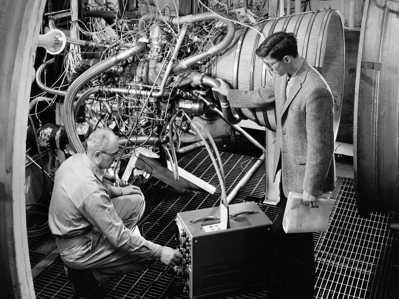
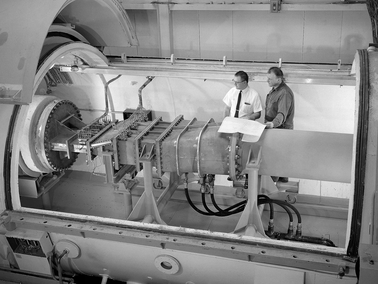
Lead Test Engineer John Kobak (right) and a technician use an oscilloscope to test the installation of a Pratt and Whitney RL-10 engine in the Propulsion Systems Laboratory at the National Aeronautics and Space Administration (NASA) Lewis Research Center. In 1955 the military asked Pratt and Whitney to develop hydrogen engines specifically for aircraft. The program was canceled in 1958, but Pratt and Whitney decided to use the experience to develop a liquid-hydrogen rocket engine, the RL-10. Two of the 15,000-pound-thrust RL-10 engines were used to power the new Centaur second-stage rocket. Centaur was designed to carry the Surveyor spacecraft on its mission to soft-land on the Moon. Pratt and Whitney ran into problems while testing the RL-10 at their facilities. NASA Headquarters assigned Lewis the responsibility for investigating the RL-10 problems because of the center’s long history of liquid-hydrogen development. Lewis’ Chemical Rocket Division began a series of tests to study the RL-10 at its Propulsion Systems Laboratory in March 1960. The facility contained two test chambers that could study powerful engines in simulated altitude conditions. The first series of RL-10 tests in early 1961 involved gimballing the engine as it fired. Lewis researchers were able to yaw and pitch the engine to simulate its behavior during a real flight.
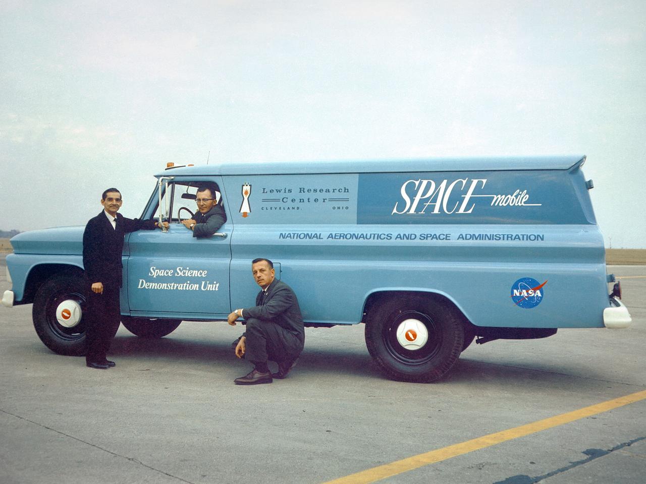
Members of Lewis’ Educational Services Office pose with one of the center’s Spacemobile space science demonstration units. Unlike its predecessor, the NACA, the new NASA space agency considered public outreach one of its core tenets. The early astronauts were lionized and new technologies touted. Lewis, which had previously been a closed laboratory, began hosting open houses and elaborate space fairs in the early 1960s. In addition, the center initiated educational programs that worked with local schools and a robust speaker’s bureau that explained NASA activities to the community. One aspect of these efforts was the Spacemobile Program. These vehicles included a delegated speaker, exhibits, models, and other resources. The Spacemobiles, which made forays across the Midwest, were extremely active throughout the 1960s.
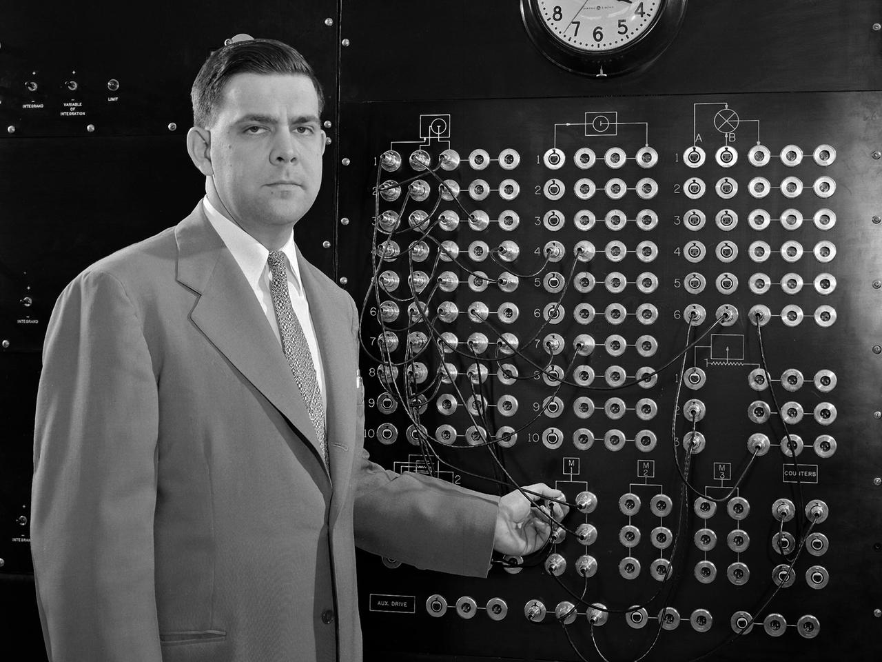
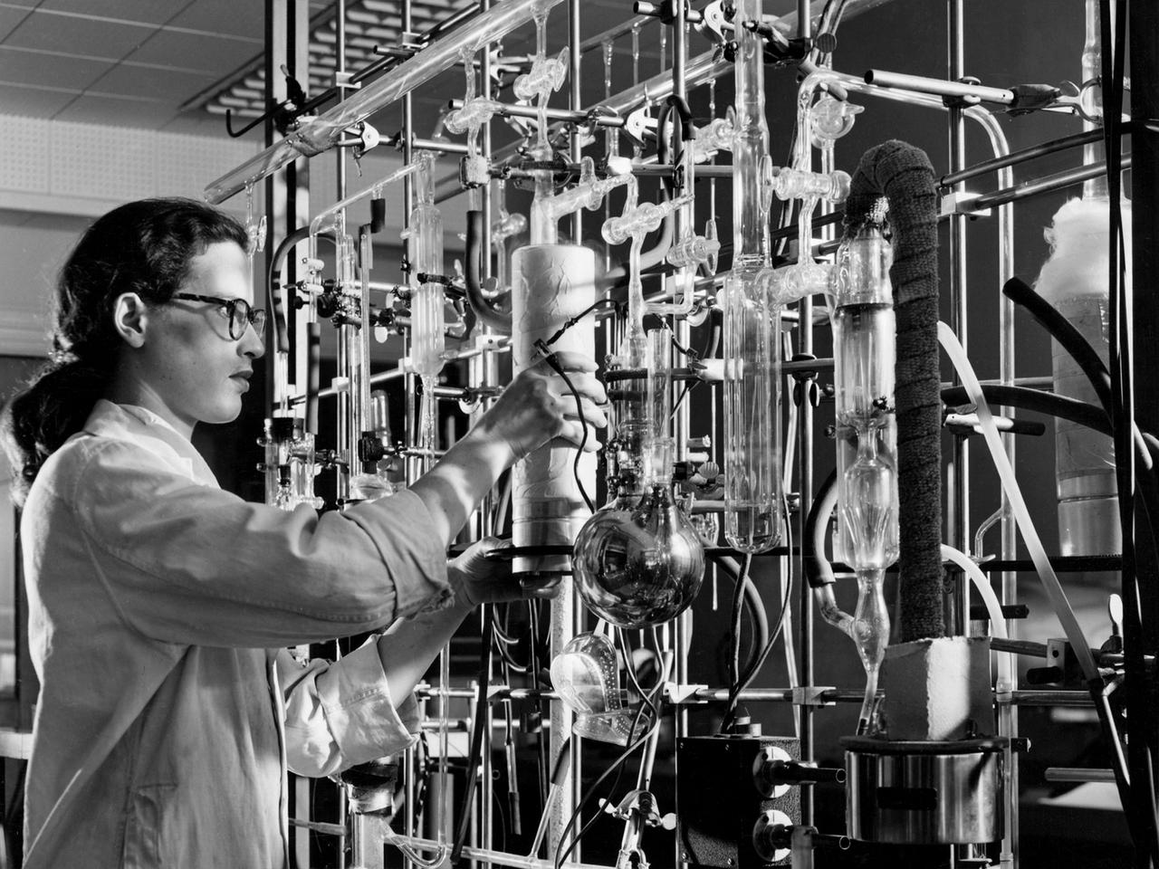
Harry Mergler stands at the control board of a differential analyzer in the new Instrument Research Laboratory at the National Advisory Committee for Aeronautics (NACA) Lewis Flight Propulsion Laboratory. The differential analyzer was a multi-variable analog computation machine devised in 1931 by Massachusetts Institute of Technology researcher and future NACA Committee member Vannevar Bush. The mechanical device could solve computations up to the sixth order, but had to be rewired before each new computation. Mergler modified Bush’s differential analyzer in the late 1940s to calculate droplet trajectories for Lewis’ icing research program. In four days Mergler’s machine could calculate what previously required weeks. NACA Lewis built the Instrument Research Laboratory in 1950 and 1951 to house the large analog computer equipment. The two-story structure also provided offices for the Mechanical Computational Analysis, and Flow Physics sections of the Physics Division. The division had previously operated from the lab’s hangar because of its icing research and flight operations activities. Mergler joined the Instrument Research Section of the Physics Division in 1948 after earning an undergraduate degree in Physics from the Case Institute of Technology. Mergler’s focus was on the synthesis of analog computers with the machine tools used to create compressor and turbine blades for jet engines.

A cancer patient undergoes treatment in the Neutron Therapy Treatment Facility, or Cylotron, at the National Aeronautics and Space Administration (NASA) Lewis Research Center. After World War II Lewis researchers became interested in nuclear energy for propulsion. The focused their efforts on thermodynamics and strength of materials after radiation. In 1950 an 80-person Nuclear Reactor Division was created, and a cyclotron was built behind the Materials and Structures Laboratory. An in-house nuclear school was established to train these researchers in their new field. NASA cancelled its entire nuclear program in January 1973, just as the cyclotron was about to resume operations after a major upgrade. In 1975 the Cleveland Clinic Foundation partnered with NASA Lewis to use the cyclotron for a new type of radiation treatment for cancer patients. The cyclotron split beryllium atoms which caused neutrons to be released. The neutrons were streamed directly at the patient’s tumor. The facility had a dual-beam system that could target the tumor both vertically and horizontally. Over the course of five years, the cyclotron was used to treat 1200 patients. It was found to be particularly effective on salivary gland, prostrate, and other tumors. It was not as successful with tumors of the central nervous system. The program was terminated in 1980 as the Clinic began concentrating on non-radiation treatments.
An Atlas/Centaur mass model undergoes a separation test inside the Space Power Chambers at NASA Lewis Research Center. Lewis was in the midst of an extensive effort to prepare the Centaur second-stage rocket for its missions to send the Surveyor spacecraft to the moon as a precursor to the Apollo missions. As part of these preparations, Lewis management decided to convert its Altitude Wind Tunnel into two large test chambers—the Space Power Chambers. The conversion included the removal of the tunnel’s internal components and the insertion of bulkheads to seal off the new chambers within the tunnel. One chamber could simulate conditions found at 100 miles altitude, while this larger chamber simulated the upper atmosphere. In this test series, researchers wanted to verify that the vehicle’s retrorockets would properly separate the Centaur from the Atlas. The model was suspended horizontally on a trolley system inside chamber. A net was hung at one end to catch the jettisoned Atlas model. The chamber atmosphere was reduced to a pressure altitude of 100,000 feet, and high-speed cameras were synchronized to the ignition of the retrorockets. The simulated Centaur is seen here jettisoning from the Atlas out of view to the right. The study resulted in a new jettison method that would significantly reduce the separation time and thus minimize the danger of collision between the two stages during separation.
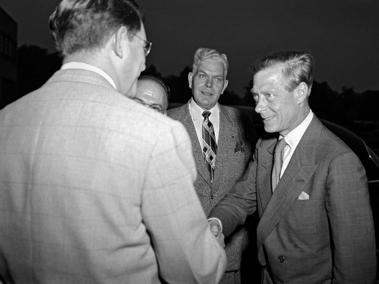
Edward Saxe-Coburg-Gotha, the Duke of Windsor, visits the National Advisory Committee for Aeronautics (NACA) Lewis Flight Propulsion Laboratory in Cleveland, Ohio. He is seen in this photograph shaking hands with Associate Director Abe Silverstein. Lewis Director Ray Sharp is in the background. Cleveland mayor Thomas Burke and other local officials were also on hand to greet Edward. Silverstein led the group on a tour of Lewis’ new 8- by 6-Foot Supersonic Wind Tunnel where the Duke inquired about the operation of the facility’s flexible walls, the types of components tested, and the generation of airflow. The Duke was in town in 1951 to promote his new autobiography, A King’s Story, at the American Booksellers Convention. Edward had assumed the British throne in January 1936, only to renounce the position less than a year later to controversially marry Wallis Simpson. Ongoing concerns over the couple’s relationship to the German government resulted in his World War II assignment to the Bahamas. Edward spent the remainder of his life in France.
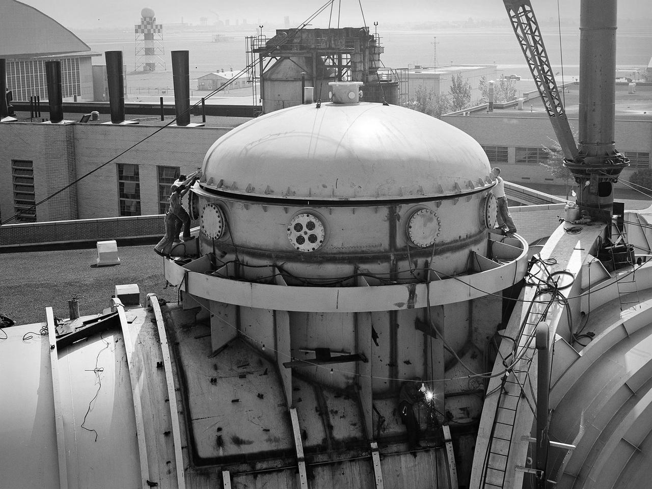
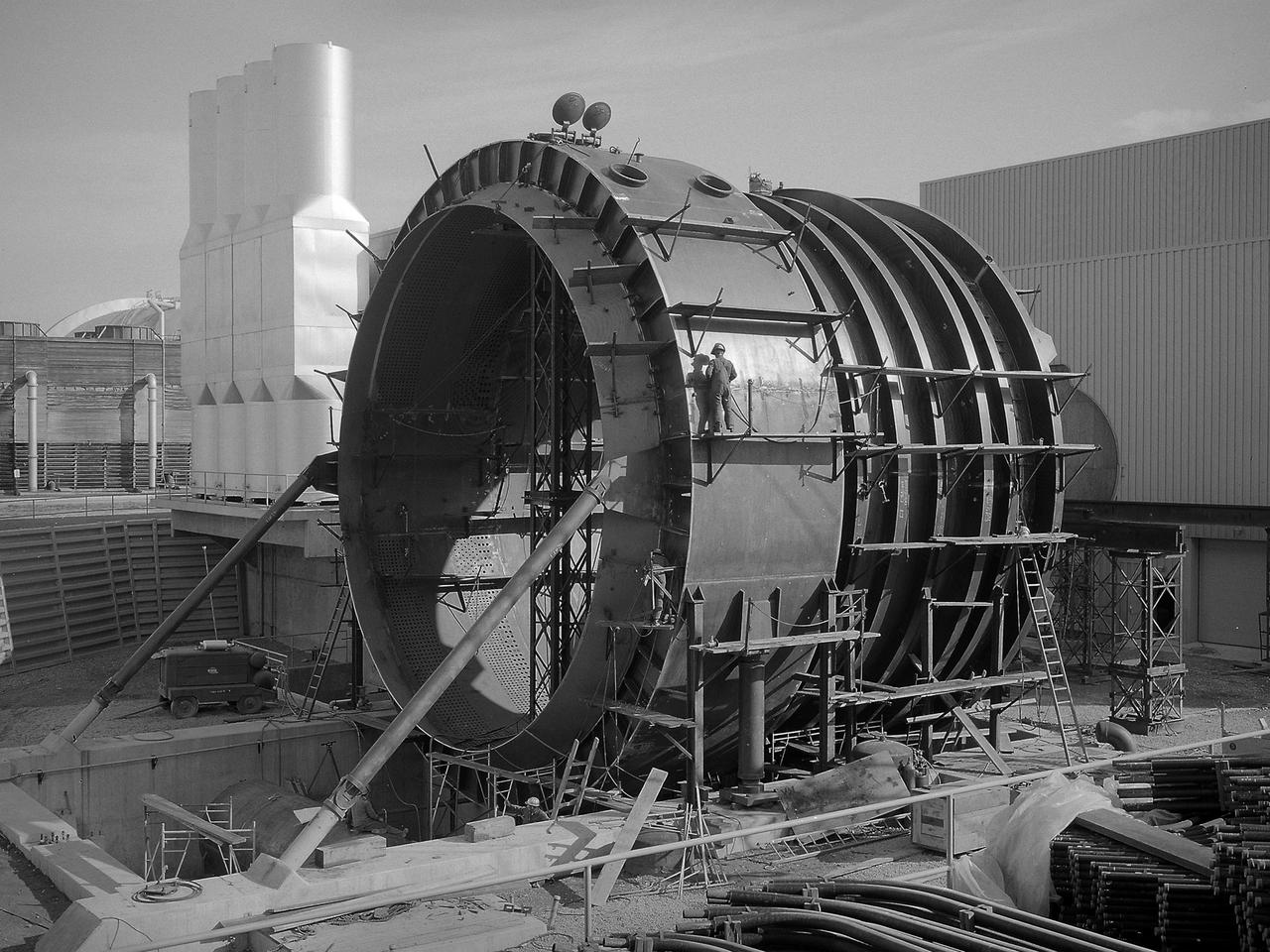
This 22.5-foot-diameter domed lid was added to the Space Power Chambers to allow the vertical installation of a Centaur second-stage rocket into the vacuum tank at the National Aeronautics and Space Administration (NASA) Lewis Research Center. The lid could be removed using a crane so that the Centaur could be lowered into the chamber. After a year of additional construction, the new dome and extension were completed in September 1963. The feature became the facility’s distinctive attribute. The modifications to the facility began two years earlier, however. In 1961, NASA Lewis management decided to convert the Altitude Wind Tunnel into two large test chambers and later renamed it the Space Power Chambers. The conversion included the removal of the tunnel’s internal components and the insertion of bulkheads to seal off the new chambers within the tunnel. The 100-foot-long vacuum tank was created in the east leg of the tunnel, which was 31 feet in diameter at one end and 27 feet in diameter at the other. With the transfer of the Centaur second-stage rocket program to NASA Lewis in October 1962, the newly completed Space Power Chambers facility had to be modified to accommodate the space vehicle. The goal of the test engineers was to subject the Centaur to long durations in conditions that would replicate those encountered during its missions in space. The facility was used for a variety of tests on the Centaur second-stage rocket until the early 1970s.
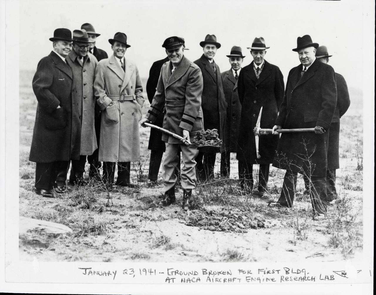
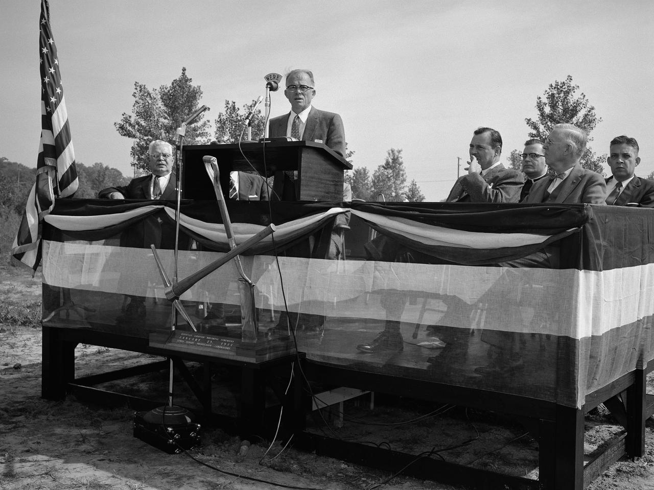
January 23, 1941 groundbreaking ceremony at the NACA Aircraft Engine Research Laboratory: left to right (does not include two individuals obscured from view behind Maj. Brett and Dr. Lewis): • William R. Hopkins – Cleveland City Manager from 1924-1930, was personally responsible for planning and acquiring the land for the Cleveland Airport. The airport’s huge capacity for handling aircraft was one factor in selecting Cleveland for the site of the research center. The Cleveland Airport was renamed Cleveland Hopkins airport in his honor in 1951. • Major John Berry – Cleveland Airport Manager • Edward R. Sharp – GRC’s first director, serving from 1942 to his retirement in 1961. He came to Cleveland in 1941 as the construction manager for the new facility. • Frederick C. Crawford – President of Thompson Products, which became the Thompson-Ramo-Woolridge Corporation (TRW) in 1958. Crawford was, at the time, also president of the Cleveland Chamber of Commerce. He began in 1939 to campaign for Cleveland as the location for the new NACA facility. • Major George H. Brett – A Cleveland native, Brett served in WWI and was commanding officer at Wright Field in Dayton, Ohio before becoming chief of the Army Air Corps. • Dr. Edward P. Warner – Acting chairman of the NACA. • Captain Sydney M. Kraus – Officer in charge of Navy procurement • Edward Blythin – Mayor of Cleveland • Dr. George Lewis – Director of Aeronautical Research for the NACA from 1924-1947, Lewis devoted his life to building a scientific basis for aeronautical engineering. The Cleveland laboratory was renamed the Lewis Flight Propulsion Laboratory in his honor in 1948. A description of the event, based on newspaper accounts and later NASA publications is as follows: On January 23, 1941, a brief groundbreaking ceremony at the site marked the start of construction. Dr. George W. Lewis, director of research for the NACA, loosened the soil with a
The Fan Noise Test Facility built at the Lewis Research Center to obtain far-field noise data for the National Aeronautics and Space Administration (NASA) and General Electric Quiet Engine Program. The engine incorporated existing noise reduction methods into an engine of similar power to those that propelled the Boeing 707 or McDonnell-Douglas DC-8 airliner. The new the low-bypass ratio turbofan engines of the 1960s were inherently quieter than their turbojet counterparts, researchers had a better grasp of the noise generation problem, and new acoustic technologies had emerged. Lewis contracted General Electric in 1969 to build and aerodynamically test three experimental engines with 72-inch diameter fans. The engines were then brought to Lewis and tested with an acoustically treated nacelle. This Fan Noise Test Facility was built off of the 10- by 10-Foot Supersonic Wind Tunnel’s Main Compressor and Drive Building. Lewis researchers were able to isolate the fan’s noise during these initial tests by removing the core of the engine. The Lewis test rig drove engines to takeoff tip speeds of 1160 feet per second. The facility was later used to test a series of full-scale model fans and fan noise suppressors to be used with the quiet engine. NASA researchers predicted low-speed single-stage fans without inlet guide vanes and with large spacing between rotors and stators would be quieter. General Electric modified a TF39 turbofan engine by removing the the outer protion of the fan and spacing the blade rows of the inner portion. The tests revealed that the untreated version of the engine generated less noise than was anticipated, and the acoustically treated nacelle substantially reduced engine noise.
Walter Olson, Chief of the Chemistry and Energy Conversion Division, examines equipment in the new Energy Conversion Laboratory at the National Aeronautics and Space Administration (NASA) Lewis Research Center. The Energy Conversion Laboratory, built in 1961 and 1962, was a modest one-story brick structure with 30,000 square feet of working space. It was used to study fundamental elements pertaining to the conversion of energy into electrical power. The main application for this was space power, but in the 1970s it would also be applied for terrestrial applications. Olson joined the Lewis staff as a fuels and combustion researcher in 1942 and was among a handful or researchers who authored the new laboratory’s first technical report. The laboratory reorganized after the war and Olson was placed in charge of three sections of researchers in the Combustion Branch. They studied combustion and fuels for turbojets, ramjets, and small rockets. In 1950, Olson was named Chief of the entire Fuels and Combustion Research Division. In 1960 Olson was named Chief of the new Chemistry and Energy Conversion Division. It was in this role that Olson advocated for the construction of the Energy Conversion Laboratory. The new division expanded its focus from just fuels and combustion to new sources of energy and power such as solar cells, fuels cells, heat transfer, and thermionics.

Adolph Spakowski, head of the Photovoltaic Fundamentals Section at the National Aeronautics and Space Administration (NASA) Lewis Research Center, illustrated the difference between conventional silicon solar cells (rear panel) and the new thin-film cells. The larger, flexible thin-film cells in the foreground were evaluated by Lewis energy conversion specialists for possible future space use. The conventional solar cells used on most spacecraft at the time were both delicate and heavy. For example, the Mariner IV spacecraft required 28,000 these solar cells for its flyby of Mars in 1964. NASA Lewis began investigating cadmium sulfide thin-film solar cells in 1961. The thin-film cells were made by heating semiconductor material until it evaporated. The vapor was then condensed onto an electricity-producing film only one-thousandth of an inch thick. The physical flexibility of the new thin-film cells allowed them to be furled, or rolled up, during launch. Spakowski led an 18-month test program at Lewis to investigate the application of cadmium sulfide semiconductors on a light metallized substrate. The new thin-film solar cells were tested in a space simulation chamber at a simulated altitude of 200 miles. Sunlight was recreated by a 5000-watt xenon light. Two dozen cells were exposed to 15 minutes of light followed by 15 minutes of darkness to test their durability in the constantly changing illumination of Earth orbit.
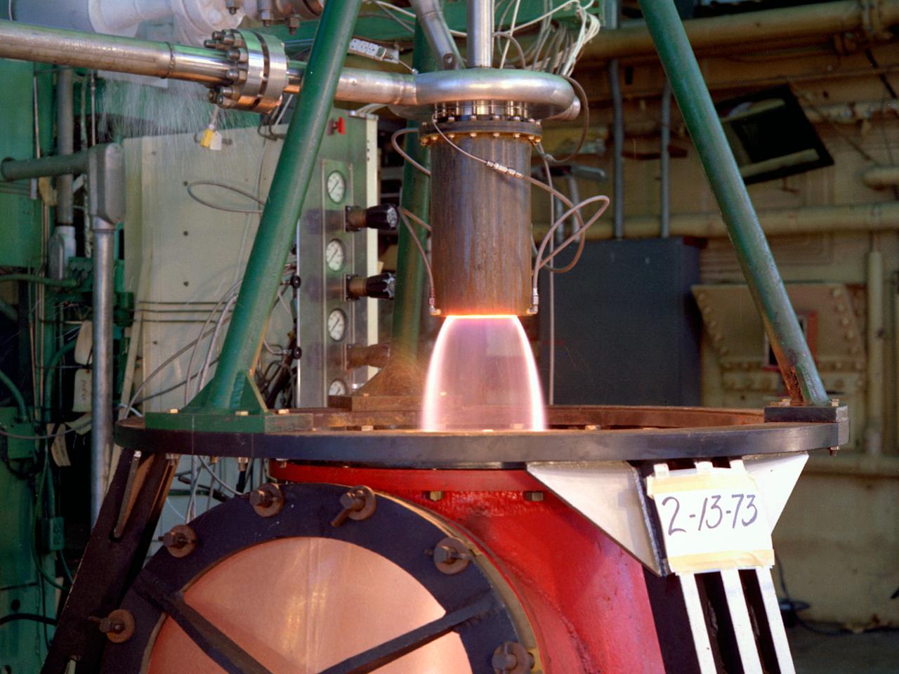
The 50-foot diameter primary cooler for the new Propulsion Systems Laboratory No. 3 and 4 facility constructed at the National Aeronautics and Space Administration (NASA) Lewis Research Center. In 1968, 20 years after planning began for the original Propulsion Systems Laboratory test chambers, No. 1 and 2, NASA Lewis began preparations to add two additional and more powerful chambers. The move coincided with the center’s renewed focus on aeronautics in 1966. The new 40-foot long and 24-foot diameter chambers were capable of testing engines twice as powerful any then in existence and significantly larger than those in the original two test chambers. After exiting the engine nozzle, the hot exhaust air passed through a 17-foot diameter water exhaust duct and the 50-foot diameter primary cooler. Twenty-seven hundred water-filled tubes inside the cooler reduced the temperature of the air flow as it passed between the tubes from 3000 to 600 °F. A spray cooler further reduced the temperature of the gases to 150 °F before they were sent to the Central Air Building. Excavations for the new facility were completed by October 1967, and the shell of the building was completed a year later. In September 1968, work began on the new test chambers and associated infrastructure. Construction was completed in late 1972, and the first test was scheduled for February 1973.
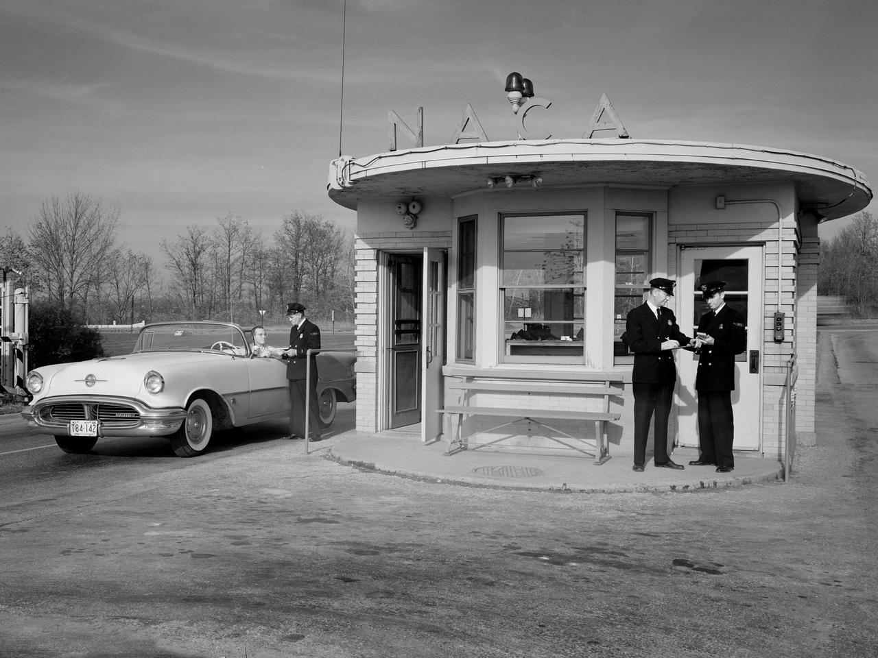
A vehicle leaves the National Advisory Committee for Aeronautics (NACA) Lewis Flight Propulsion Laboratory in Cleveland, Ohio. The guard house was on the main entrance to the laboratory from Brookpark Road. The original building was fairly small and easily crowded. In the early 1960s a new security facility was built several hundred feet beyond the original guard house. The original structure remained in place for several years, but was not utilized. The structure seen in this photograph was replaced in 2011 by a new building and entrance configuration. In September 1955, approximately a year before this photo was taken, the security staff was given new navy blue uniforms, seen here.
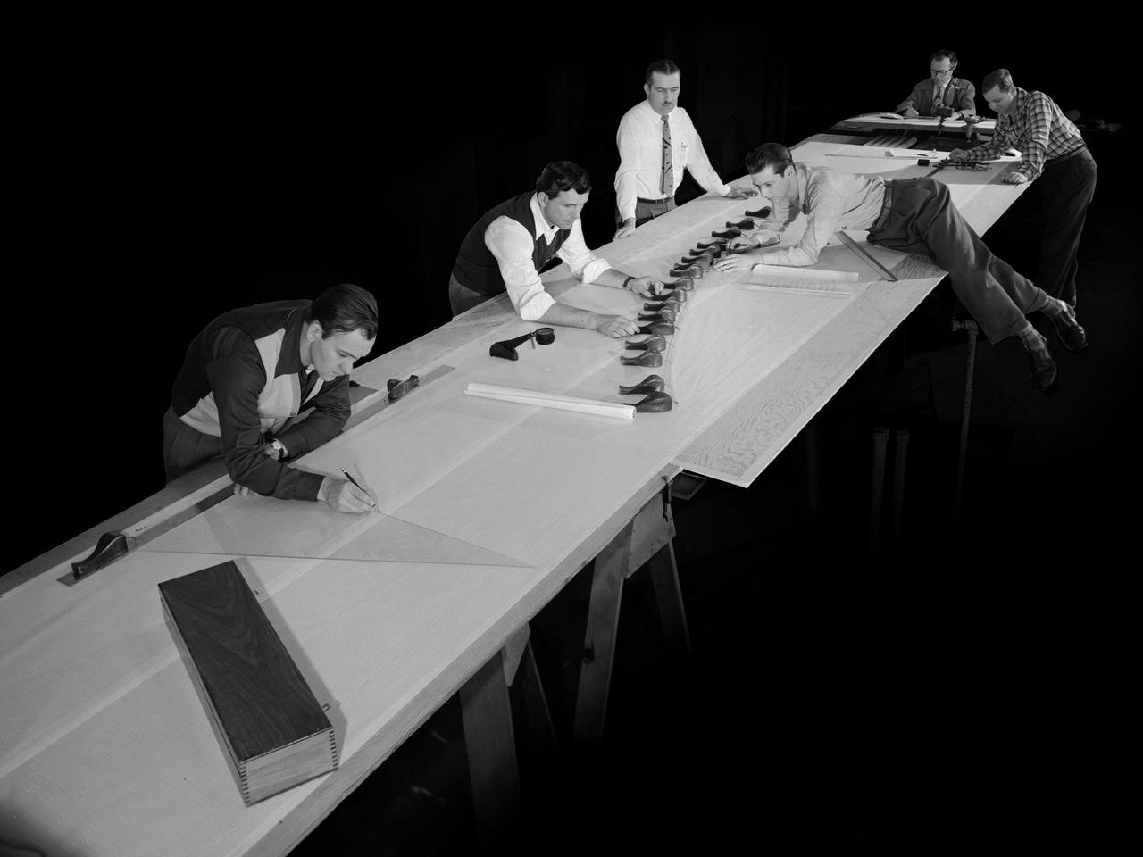
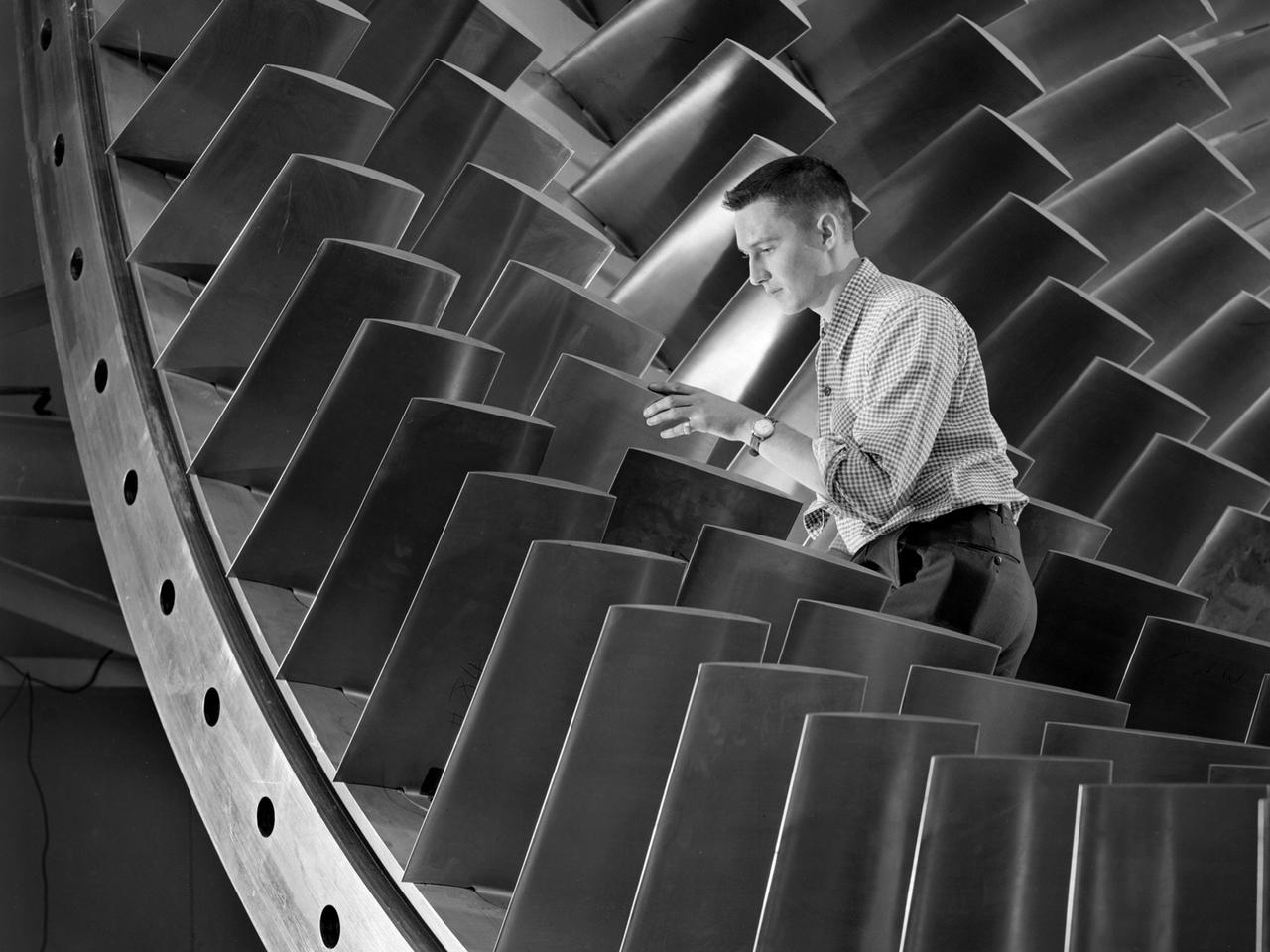
Draftsmen in the Materials and Stresses Building at the National Advisory Committee for Aeronautics (NACA) Lewis Flight Propulsion Laboratory create a template for a compressor using actual compressor blades. The Compressor and Turbine Division contained four sections of researchers dedicated to creating better engine components. The Materials and Thermodynamics Division studied the strength, durability, heat transfer characteristics, and physical composition of various materials. The two divisions were important to the research and development of new aircraft engines. The constant battle to increase the engine’s thrust while decreasing its overall weight resulted in additional stress on jet engine components, particularly compressors. As speed and maneuverability were enhanced, the strain on the engines and inlets grew. For decades NACA Lewis researchers continually sought to improve compressor blade design, develop stronger composite materials, and minimize flutter and inlet distortions.
Pilot Earle Boyer and researcher Henry Brandhorst prepare for a solar cell calibration flight in a Martin B-57B Canberra at the National Aeronautics and Space Administration (NASA) Lewis Research Center. Lewis was in the early stages of decades-long energy conversion and space power research effort. Brandhorst, a member of the Chemistry and Energy Conversion Division, led a team of Lewis researchers in a quest to develop new power sources to sustain spacecraft in orbit. Solar cells proved to be an important source of energy, but researchers discovered that their behavior varied at different atmospheric levels. Their standardization and calibration were critical. Brandhorst initiated a standardized way to calibrate solar cells in the early 1960s using the B-57B aircraft. The pilots would take the aircraft up into the troposphere and open the solar cell to the sunlight. The aircraft would steadily descend while instruments recorded how much energy was being captured by the solar cell. From this data, Brandhorst could determine the estimated power for a particular solar cell at any altitude. Pilot Earle Boyer joined NASA Lewis in October 1962. He had flown Convair F-102 Delta Dagger fighters in the Air Force and served briefly in the National Guard before joining the Langley Research Center. Boyer was only at Langley a few months before he transferred to Cleveland. He flew the B-57B, a Convair F-106 Delta Dart, Gulfstream G-1 with an experimental turboprop, Learjet and many other aircraft over the next 32 years at Lewis.
Attendees listen during the May 22, 1956 Inspection of the new 10- by 10-Foot Supersonic Wind Tunnel at the National Advisory Committee for Aeronautics (NACA) Lewis Flight Propulsion Laboratory. The facility, known at the time as the Lewis Unitary Plan Tunnel, was in its initial stages of operation. The $33 million 10- by 10 was the most powerful wind tunnel in the nation. Over 150 guests from industry, other NACA laboratories, and the media attended the event. The speakers, from left to right in the front row, addressed the crowd before the tour. Lewis Director Raymond Sharp began the event by welcoming the visitors to the laboratory. NACA Director Hugh Dryden discussed Congress’ Unitary Plan Act and its effect on the creation of the facility. Lewis Associate Director Abe Silverstein discussed the need for research tools and the 10- by 10’s place among the NACA’s other research facilities. Lewis Assistant Director Eugene Wasielewski described the detailed design work that went into the facility. Carl Schueller, Chief of the 10- by 10, described the tunnel’s components and how the facility operated. Robert Godman led the tour afterwards. The 10- by 10 can test engines up to five feet in diameter at supersonic speeds and simulated altitudes of 30 miles. Its main purpose is to investigate problems relating to engine inlet and outlet geometry, engine matching and interference effects, and overall drag. The tunnel’s 250,000-horsepower electric motor drive, the most powerful of its kind in the world, creates air speeds between Mach 2.0 and 3.5.
A materials researcher at the NACA’s Lewis Flight Propulsion Laboratory examines a surface crack detection apparatus in the Materials and Stresses Building during December 1952. Materials research was an important aspect of propulsion technology. Advanced engine systems relied upon alloys, and later composites, that were strong, lightweight, and impervious to high temperatures. Jet engines which became increasingly popular in the late 1940s, produced much higher temperatures than piston engines. These higher temperatures stressed engine components, particularly turbines. Although Lewis materials research began during World War II, the Materials and Thermodynamics Division was not created until 1949. Its primary laboratories were located in the Materials and Stresses Building. The group sought to create new, improved materials and to improve engine design through increased understanding of materials. The Lewis materials researchers of the 1950s made contributions to nickel-aluminum alloys, cermet blades, metal matrix composites, oxide dispersion strengthened superalloys, and universal slopes.
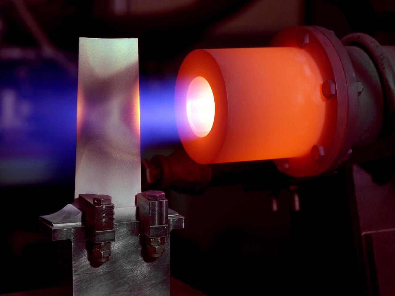
A 1-foot long stator blade with a thermal coating subjected to intense heat in order to test its strength at the National Aeronautics and Space Administration (NASA) Lewis Research Center. Lewis researchers sought to determine optimal types of ceramic coatings to increase the durability of metals. The research was primarily intended to support the design of stator blades for high-performance axial-flow compressor and turbofan engines. The coatings reduced the temperature of the metal and the amount of required cooling. As engines became more and more sophisticated, compressor blades were required to withstand higher and higher temperatures. Lewis researchers developed a dual-layer thermal-barrier coating that could be applied to turbine vanes and blades and combustion liners. This new sprayable thermal-barrier coating was evaluated for its durability, strength, fatigue, and aerodynamic penalties. This hot-gas rig fired the scorching gas at the leading edge of a test blade. The blade was cooled by an internal air flow. The blades were heated at two different velocities during the program. When using Mach 0.3 gases the entire heating and cooling cycle only lasted 30 seconds. The cycle lasted 60 minutes during tests at Mach 1.
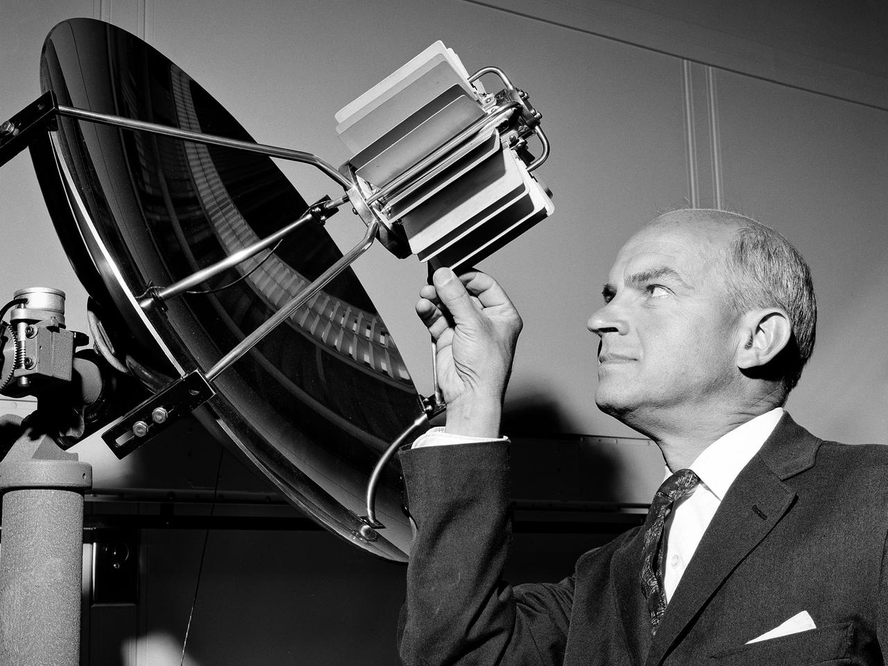
An engineer examines the main compressor for the 10- by 10-Foot Supersonic Wind Tunnel at the National Advisory Committee for Aeronautics (NACA) Lewis Flight Propulsion Laboratory. The engineers were preparing the new wind tunnel for its initial runs in early 1956. The 10- by 10 was the most powerful propulsion wind tunnel in the nation. The facility was part of Congress’ Unitary Plan Act which coordinated wind tunnel construction at the NACA, Air Force, industry, and universities. The 10- by 10 was the largest of the three NACA tunnels built under the act. The 20-foot diameter eight-stage axial flow compressor, seen in this photograph, could generate air flows up to Mach 2.5 through the test section. The stainless steel compressor had 584 blades ranging from 1.8 to 3.25 feet in length. This main compressor was complemented by a secondary axial flow compressor. Working in tandem the two could generate wind streams up to Mach 3.5. The Cleveland Chamber of Commerce presented NACA Lewis photographer Bill Bowles with a second place award for this photograph in their Business and Professional category. The photograph was published in October 1955 edition of its periodical, The Clevelander, which highlighted local professional photographers. Fellow Lewis photographer Gene Giczy won second place in another category for a photograph of Cleveland Municipal Airport.
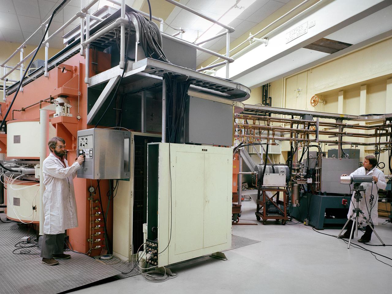
Researchers check the cyclotron in the Materials and Stresses Building at the National Aeronautics and Space Administration (NASA) Lewis Research Center. The Materials and Stresses Building, built in 1949, contained a number of laboratories to test the strength, diffusion, and other facets of materials. The materials could be subjected to high temperatures, high stresses, corrosion, irradiation, and hot gasses. The Physics of Solids Laboratory included a cyclotron, cloud chamber, helium cryostat, and metallurgy cave. The cyclotron was built in the early 1950s to test the effects of radiation on different materials so that the proper materials could be used to construct a nuclear aircraft engine and other components. By the late 1950s, the focus had shifted to similar studies for rockets. NASA cancelled its entire nuclear program in January 1973, and the cyclotron was mothballed. In 1975 the Cleveland Clinic Foundation partnered with NASA Lewis to use the cyclotron to treat cancer patients with a new type of radiation therapy. The cyclotron split beryllium atoms which caused neutrons to be released. The neutrons were streamed directly at the patient’s tumor. Over the course of five years, the cyclotron was used to treat 1200 patients. The program was terminated in 1980 as the Clinic shifted its efforts to concentrate on non-radiation treatments. The Lewis cyclotron was mothballed for a number of years before being demolished.
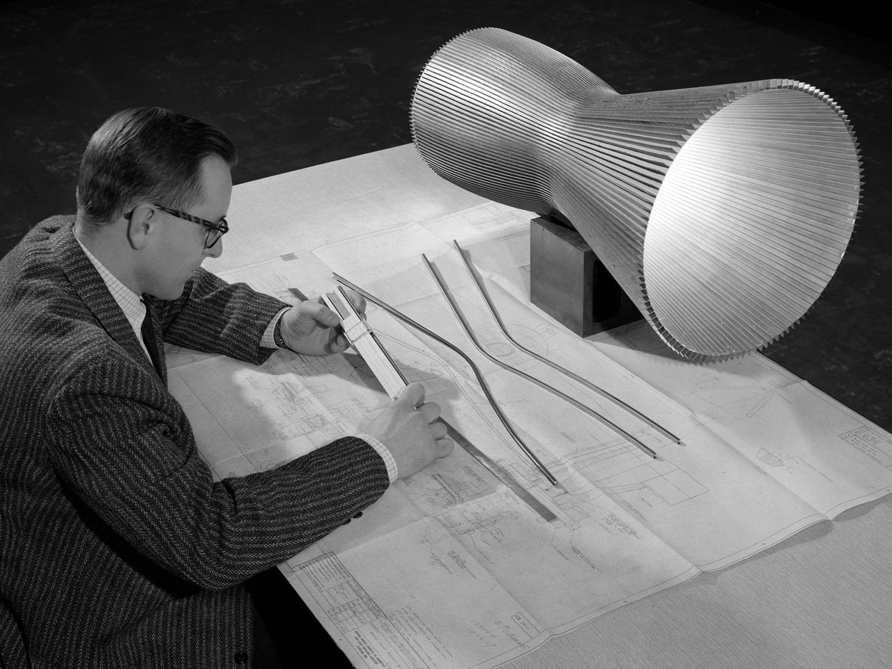
An engineer at the National Aeronautics and Space Administration (NASA) Lewis Research Center examines a drawing showing the assembly and details of a 20,000-pound thrust regeneratively cooled rocket engine. The engine was being designed for testing in Lewis’ new Rocket Engine Test Facility, which began operating in the fall of 1957. The facility was the largest high-energy test facility in the country that was capable of handling liquid hydrogen and other liquid chemical fuels. The facility’s use of subscale engines up to 20,000 pounds of thrust permitted a cost-effective method of testing engines under various conditions. The Rocket Engine Test Facility was critical to the development of the technology that led to the use of hydrogen as a rocket fuel and the development of lightweight, regeneratively-cooled, hydrogen-fueled rocket engines. Regeneratively-cooled engines use the cryogenic liquid hydrogen as both the propellant and the coolant to prevent the engine from burning up. The fuel was fed through rows of narrow tubes that surrounded the combustion chamber and nozzle before being ignited inside the combustion chamber. The tubes are visible in the liner sitting on the desk. At the time, Pratt and Whitney was designing a 20,000-pound thrust liquid-hydrogen rocket engine, the RL-10. Two RL-10s would be used to power the Centaur second-stage rocket in the 1960s. The successful development of the Centaur rocket and the upper stages of the Saturn V were largely credited to the work carried out Lewis.
A Lockheed F-94B Starfire on the hangar apron at the National Aeronautics and Space Administration (NASA) Lewis Research Center in Cleveland, Ohio. The Air Force contracted Lockheed in November 1948 to create the new F-94s fighters. The first test flight occurred only months later in April 1949. This quick turnaround was due to the fact that the F-94 was based largely on the TF-80 fighter and constructed with parts from the P-80, including its two General Electric I-40 turbojet engines. The F-94Bs entered the Korean War in late 1951, but were initially prevented from flying over enemy territory due to fear that their fire control system would be copied by the enemy if an F-94B went down. The Starfire went on to perform scores of missions escorting B-29 and B-26 bombers deep into enemy territory and acting as interceptors against enemy fighters. In mid-1954 the F-94s were retired from active military service. Lewis acquired the F-94B Starfire in April 1956. At the time, the aircraft industry was preparing for the first use of jet engines for commercial aviation. The amount of noise generated by the engines was a major obstacle. Lewis undertook an extensive program to understand the causes of the noise and develop methods for reducing it. This program included the study of aerodynamic sound at high speed and altitude using the F-94B.
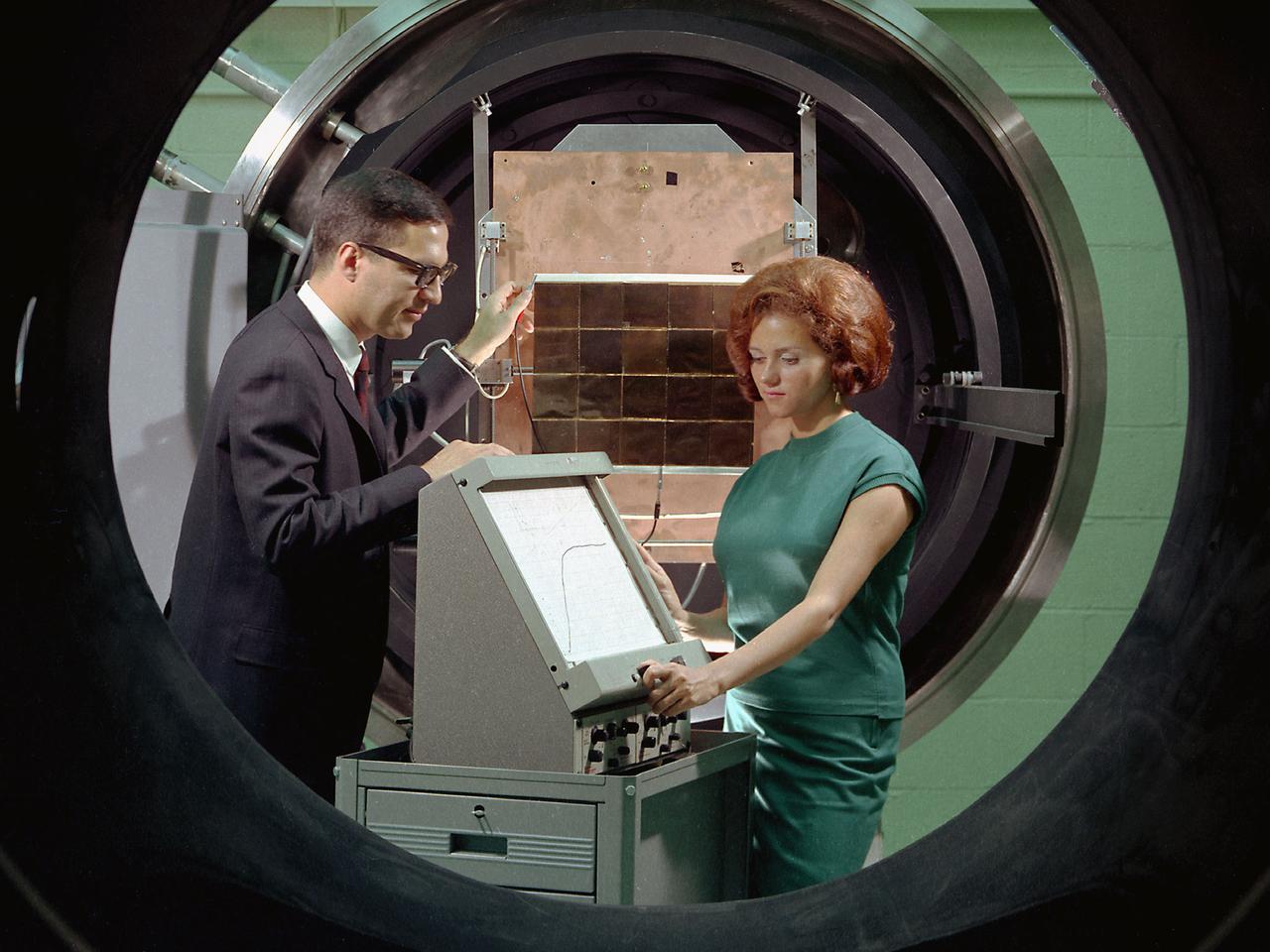
George Mazaris, works with an assistant to obtain the preliminary measurements of cadmium sulfide thin-film solar cells being tested in the Space Environmental Chamber at the National Aeronautics and Space Administration (NASA) Lewis Research Center. Lewis’ Photovoltaic Fundamentals Section was investigating thin-film alternatives to the standard rigid and fragile solar cells. The cadmium sulfide semiconductors were placed in a light, metallized substrate that could be rolled or furled during launch. The main advantage of the thin-film solar cells was their reduced weight. Lewis researchers, however, were still working on improving the performance of the semiconductor. The new thin-film solar cells were tested in a space simulation chamber in the CW-6 test cell in the Engine Research Building. The chamber created a simulated altitude of 200 miles. Sunlight was simulated by a 5000-watt xenon light. Some two dozen cells were exposed to 15 minutes of light followed by 15 minutes of darkness to test their durability in the constantly changing illumination of Earth orbit. This photograph was taken for use in a NASA recruiting publication.
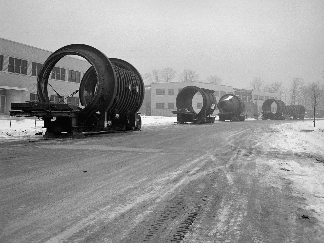
A caravan of large steel castings arrived at the National Advisory Committee for Aeronautics (NACA) Lewis Flight Propulsion Laboratory in January 1951. These pieces would serve as the two 14-foot diameter test chambers in the new Propulsion Systems Laboratory (PSL). NACA Lewis specialized in aircraft engines and offered many engine test facilities. In the late 1940s, however, the NACA realized a larger facility was required to test the newest jet engines. When completed in October 1952, PSL became the nation’s most powerful facility for testing full-scale engines at simulated flight altitudes. NACA engineers began designing the PSL in 1947, and excavations commenced in September 1949. In the spring of 1950, the facility’s supports were erected, and the two large exhaust gas coolers were installed. Work on the Access Building began in early 1951 with the arrival of the large test section pieces, seen in this photograph. The massive pieces were delivered to the area from the Henry Pratt Company by rail and then loaded on a series of flatbed trucks that transported them to Lewis. The nearest vehicle has one of the clamshell access hatches. PSL was initially used to study the jet engines of the early 1950s and ramjets for missile programs such as Navaho and Bomarc. With the advent of the space program in the late 1950s, the facility was used to investigate complex rocket engines, including the Pratt and Whitney RL-10.
The thrust stand in the Rocket Engine Test Facility at the National Aeronautics and Space Administration (NASA) Lewis Research Center in Cleveland, Ohio. The Rocket Engine Test Facility was constructed in the mid-1950s to expand upon the smaller test cells built a decade before at the Rocket Laboratory. The $2.5-million Rocket Engine Test Facility could test larger hydrogen-fluorine and hydrogen-oxygen rocket thrust chambers with thrust levels up to 20,000 pounds. Test Stand A, seen in this photograph, was designed to fire vertically mounted rocket engines downward. The exhaust passed through an exhaust gas scrubber and muffler before being vented into the atmosphere. Lewis researchers in the early 1970s used the Rocket Engine Test Facility to perform basic research that could be utilized by designers of the Space Shuttle Main Engines. A new electronic ignition system and timer were installed at the facility for these tests. Lewis researchers demonstrated the benefits of ceramic thermal coatings for the engine’s thrust chamber and determined the optimal composite material for the coatings. They compared the thermal-coated thrust chamber to traditional unlined high-temperature thrust chambers. There were more than 17,000 different configurations tested on this stand between 1973 and 1976. The Rocket Engine Test Facility was later designated a National Historic Landmark for its role in the development of liquid hydrogen as a propellant.
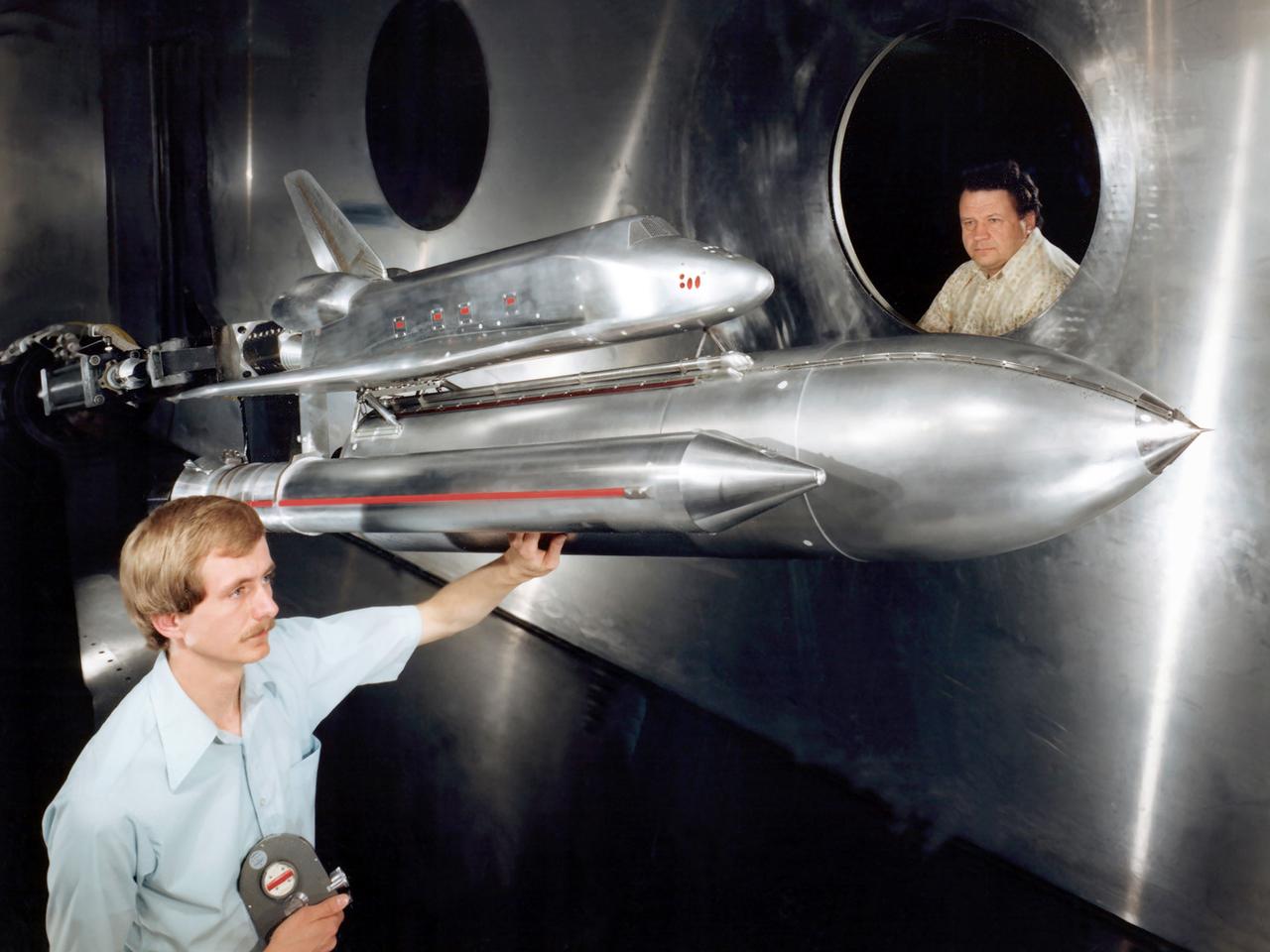
Technicians examine a scale model of the space shuttle used to obtain pressure data during tests in the 10- by 10-Foot Supersonic Wind Tunnel at the National Aeronautics and Space Administration (NASA) Lewis Research Center. Lewis researchers used the 10- by 10 tunnel extensively in the 1970s to study shuttle configurations in order to forecast conditions during an actual flight. These tests included analysis of the solid rocket boosters’ aerodynamics, orbiter forebody angle -of -attack and air speed, base heating for entire shuttle, and engine-out loads. The test seen in this photograph used a 3.5- percent scale aluminum alloy model of the entire launch configuration. The program was designed to obtain aerodynamic pressure data. The tests were part of a larger program to study possible trouble areas for the shuttle’s new Advanced Flexible Reusable Surface Insulation. The researchers obtained aeroacoustic data and pressure distributions from five locations on the model. Over 100 high-temperature pressure transducers were attached to the model. Other portions of the test program were conducted at Lewis’ 8- by 6-Foot Supersonic Wind Tunnel and the 11- by 11-Foot Transonic Wind Tunnel at Ames Research Center.
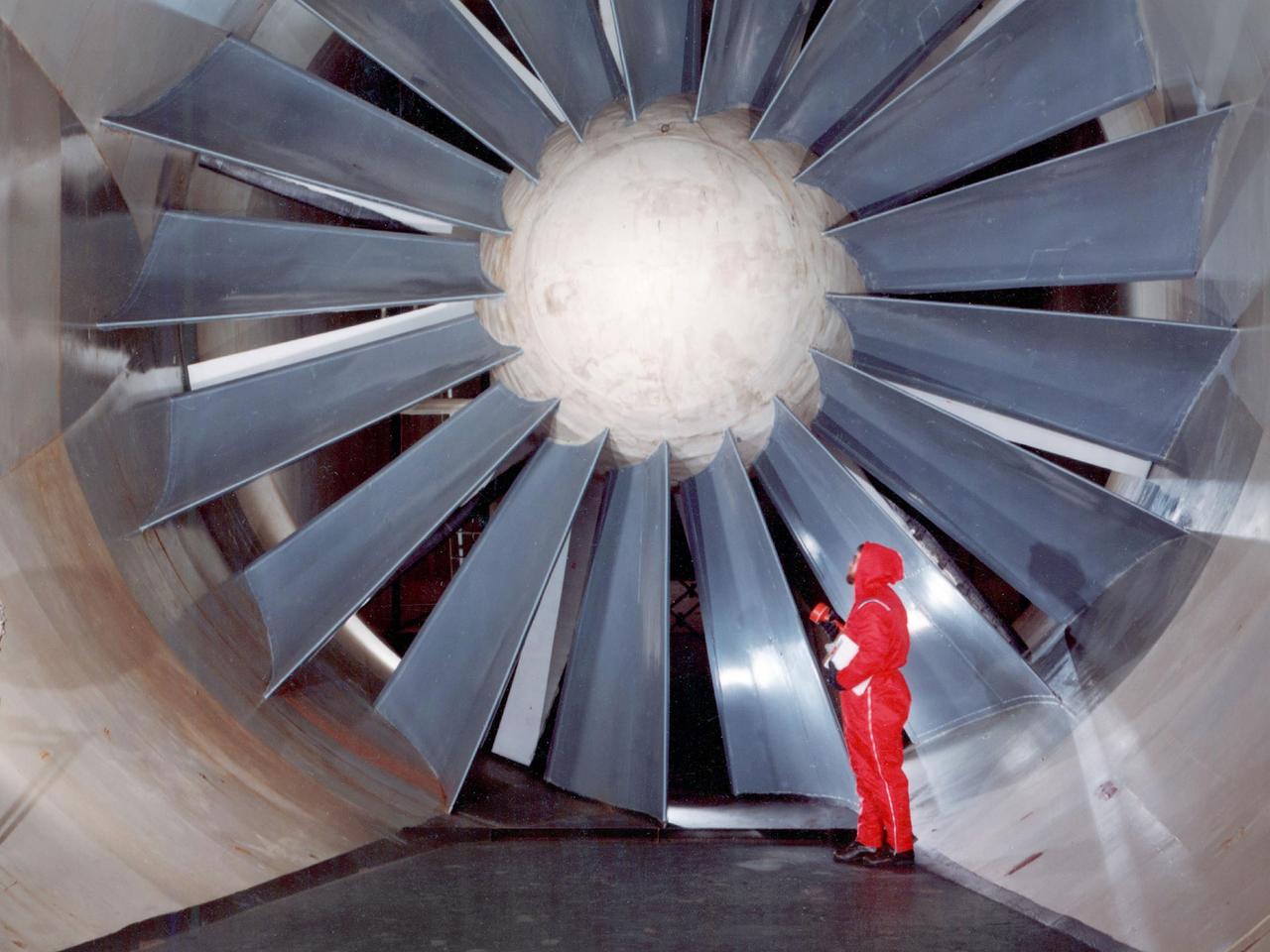
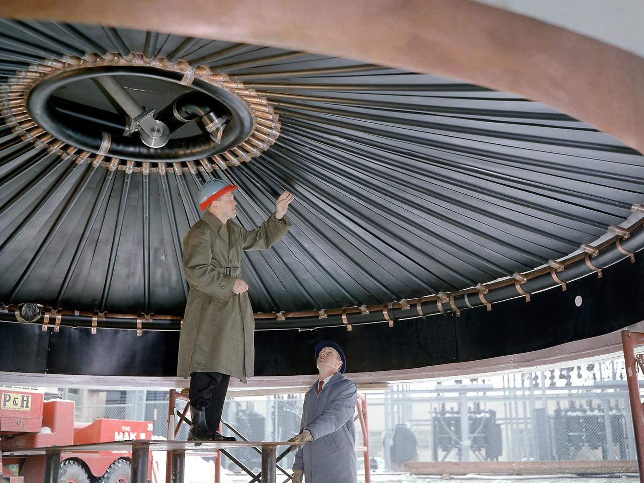
The drive fan for the Icing Research Tunnel at the National Aeronautics and Space Administration (NASA) Lewis Research Center in Cleveland, Ohio. The Lewis Icing Research Program, which began during World War II, utilized both research aircraft and the icing tunnel throughout the 1940s and 1950s. The research program was cancelled in 1958 as Lewis focused on space. The tunnel continued to be used occasionally for industrial customers in the 1960s and early 1970s. Lewis’ icing research was formally reinstituted just months before this photograph in 1978. The Icing Research Tunnel’s original 4100-horsepower induction motor was coupled directly to the 24-foot-diameter fan. Neoprene boots protected the leading edges of the 12 spruce fan blades. The system generated air speeds up to 300 miles per hour through the tunnel’s 6- by 9-foot test section. A large tail faring extended from the center of the fan to uniformly guide the airflow down the tunnel. NASA Headquarters ordered modifications to the Icing Research Tunnel in 1985 after wooden fan blades in a wind tunnel at Langley Research Center failed. Despite the fact that the large hub, seen in the center of the fan, provided an extra layer of protection against blade failure, Headquarters ordered the installation of a new set of wooden blades. The blades were ordered but not installed. The tunnel technicians instead agreed to inspect the fan after each run. A new 5000-horsepower motor was installed in 1987, and the original fan blades were finally replaced in 1993.
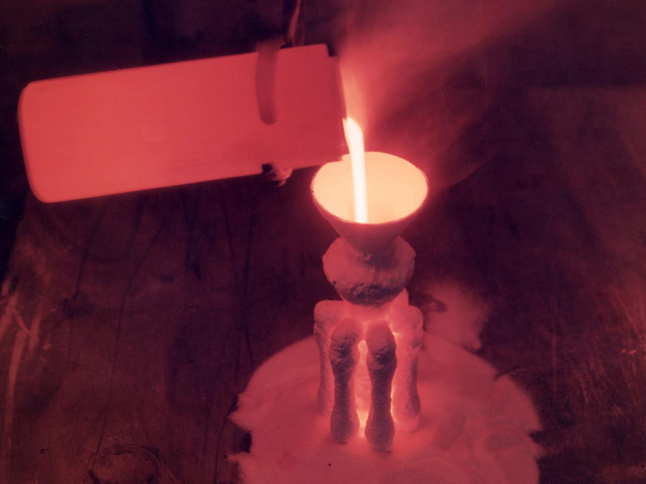
A nickel alloy developed at the National Aeronautics and Space Administration (NASA) Lewis Research Center being poured in a shop inside the Technical Services Building. Materials technology is an important element in the successful development of both advanced airbreathing and rocket propulsion systems. An array of dependable materials is needed to build different types of engines for operation in diverse environments. NASA Lewis began investigating the characteristics of different materials shortly after World War II. In 1949 the materials research group was expanded into its own division. The Lewis researchers studied and tested materials in environments that simulated the environment in which they would operate. Lewis created two programs in the early 1960s to create materials for new airbreathing engines. One concentrated on high-temperature alloys and the other on cooling turbine blades. William Klopp, Peter Raffo, Lester Rubenstein, and Walter Witzke developed Tungsten RHC, the highest strength metal at temperatures over 3500⁰ F. The men received an IR-100 Award for their efforts. Similarly a cobalt-tungsten alloy was developed by the Fatigue and Alloys Research Branch. The result was a combination of high temperature strength and magnetic properties that were applicable for generator rotor application. John Freche invented and patented a nickel alloy while searching for high temperature metals for aerospace use. NASA agreed to a three-year deal which granted Union Carbide exclusive use of the new alloy before it became public property.
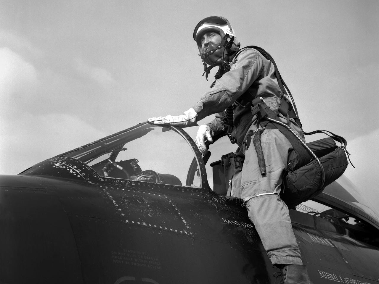
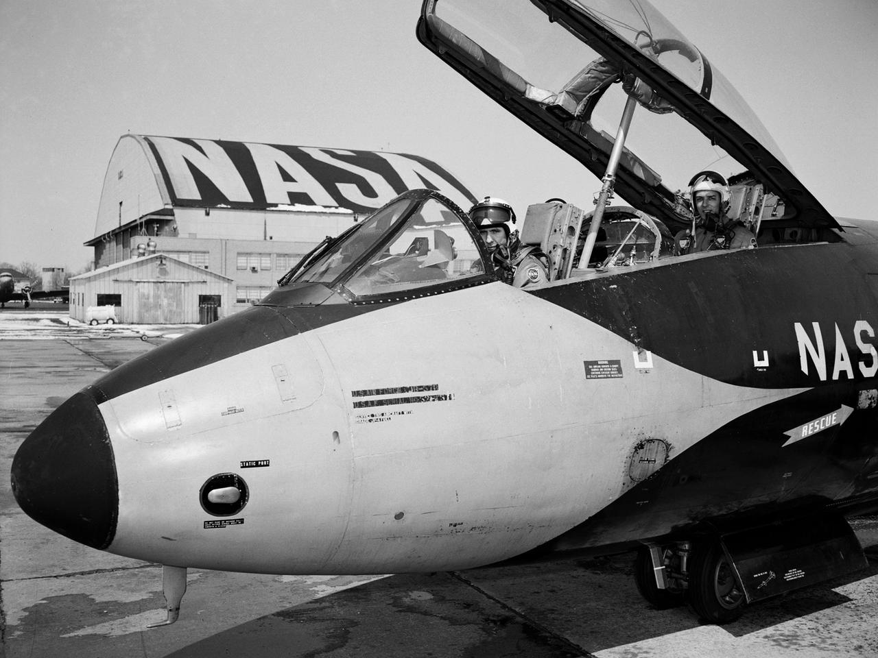
Pilot Joe Algranti climbs into the cockpit of a McDonnell F2H-2B Banshee on the tarmac at the National Advisory Committee for Aeronautics (NACA) Lewis Flight Propulsion Laboratory. Nine months later the laboratory became part of the new National Aeronautics and Space Administration, and the NACA logo was permanently removed from the hangar. Algranti served as a Navy fighter pilot from 1946 to 1947 and earned a Physics degree from the University of North Carolina. He joined the NACA Lewis staff in 1951 witnessed the technological transformation from high speed flight to space. At Lewis Algranti piloted icing research flights, operated the liquid-hydrogen pump system for Project Bee, and served as the primary test subject for the Multi-Axis Space Test Inertia Facility (MASTIF). The MASTIF was a device used to train the Mercury astronauts how to control a spinning capsule. In 1960, Algranti and fellow Lewis pilots Warren North and Harold Ream transferred to NASA’s Space Task Group at Langley to actively participate in the space program. Two years later, Algranti became the Chief of Aircraft Operations and Chief Test Pilot at NASA’s new Manned Space Center in Houston. Algranti earned notoriety in 1968 when he test flew the first Lunar Landing Training Vehicle. He operated the vehicle four minutes before being forced to eject moments before it impacted the ground. Algranti also flew the NASA’s modified Boeing 747 Shuttle Carrier Aircraft, the Super Guppy, and the KC-135 "Vomit Comet" training aircraft. He retired in 1992 with over 40 years of NASA service.
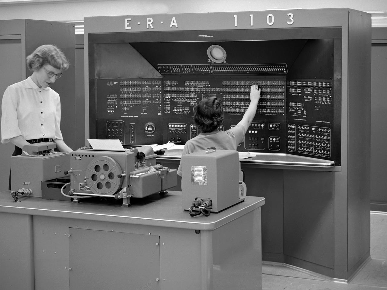
The new 10-by 10-Foot Supersonic Wind Tunnel at the Lewis Flight Propulsion Laboratory included high tech data acquisition and analysis systems. The reliable gathering of pressure, speed, temperature, and other data from test runs in the facilities was critical to the research process. Throughout the 1940s and early 1950s female employees, known as computers, recorded all test data and performed initial calculations by hand. The introduction of punch card computers in the late 1940s gradually reduced the number of hands-on calculations. In the mid-1950s new computational machines were installed in the office building of the 10-by 10-Foot tunnel. The new systems included this UNIVAC 1103 vacuum tube computer—the lab’s first centralized computer system. The programming was done on paper tape and fed into the machine. The 10-by 10 computer center also included the Lewis-designed Computer Automated Digital Encoder (CADDE) and Digital Automated Multiple Pressure Recorder (DAMPR) systems which converted test data to binary-coded decimal numbers and recorded test pressures automatically, respectively. The systems primarily served the 10-by 10, but were also applied to the other large facilities. Engineering Research Associates (ERA) developed the initial UNIVAC computer for the Navy in the late 1940s. In 1952 the company designed a commercial version, the UNIVAC 1103. The 1103 was the first computer designed by Seymour Cray and the first commercially successful computer.
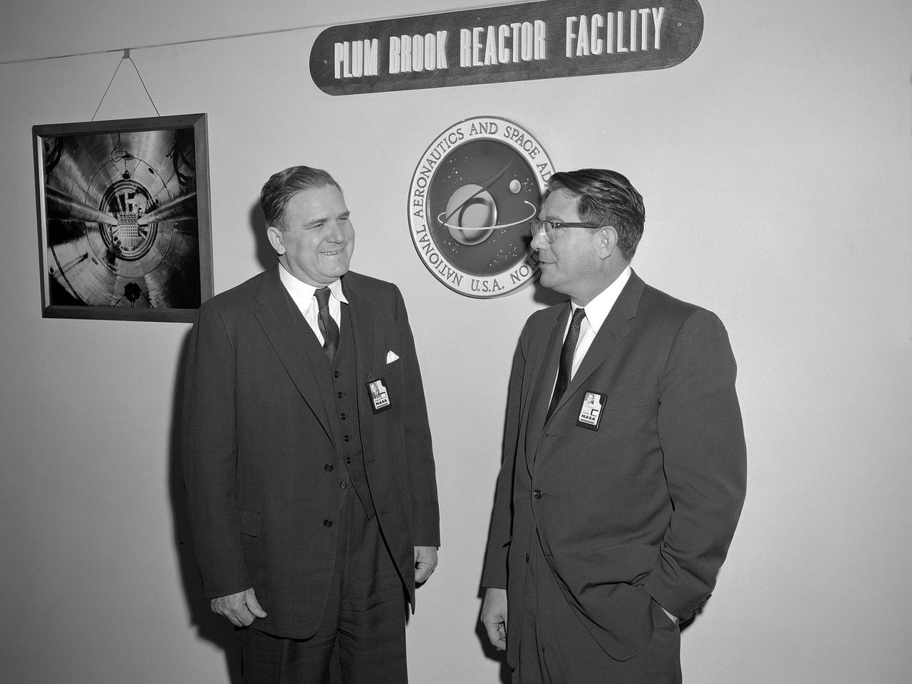
National Aeronautics and Space Administration (NASA) Administrator James Webb toured the new Plum Brook Reactor Facility in December 1961 with Abe Silverstein, the newly appointed Director of the Lewis Research Center. The 60-megawatt test reactor was built on 500 acres of the former Plum Brook Ordnance Works in Sandusky, Ohio. After nearly five years of construction, the facility went critical for the first time in June 1961. In late 1957 Hugh Dryden requested Silverstein’s assistance in creating the new space agency. After several months of commuting, Silverstein transferred to Headquarters in May 1958. Silverstein was a critical member of a team that devised a fiscal year 1960 budget and began planning missions. When NASA officially began operation on October 1, 1958, Silverstein was third in command. He directed mission planning, spacecraft design, launch operations, manned space missions, and unmanned probes. James Webb, named NASA administrator on January 7, 1961, sought to have those working on Apollo at the NASA centers report to a new Headquarters program office, not to the head of the Apollo Program. Silverstein requested to be appointed to the vacant center director position in Cleveland. He officially returned as director of the Lewis Research Center on November 1, 1961.
Rich Delgado, commanding officer of the Fleet Survey Team located at NASA's John C. Stennis Space Center, visits with Kertrina Watson Lewis, executive director of the HandsOn volunteer organization in New Orleans, during Day of Service activities Jan. 12. The Day of Service was part of the annual Martin Luther King Jr. Day observance at Stennis. During the day, Mississippi and Louisiana organizations visited the center to encourage employees to register and serve as volunteers for various community activities.

Marie Lewis, NASA Communications moderator, moderates the prelaunch news conference for SpaceX’s 18th Commercial Resupply Services (CRS-18) mission to the International Space Station, July 24, 2019, at the agency’s Kennedy Space Center in Florida. The SpaceX Falcon 9 rocket and uncrewed Dragon spacecraft are scheduled to launch July 24, 2019, from Space Launch Complex 40 at Florida’s Cape Canaveral Air Force Station.
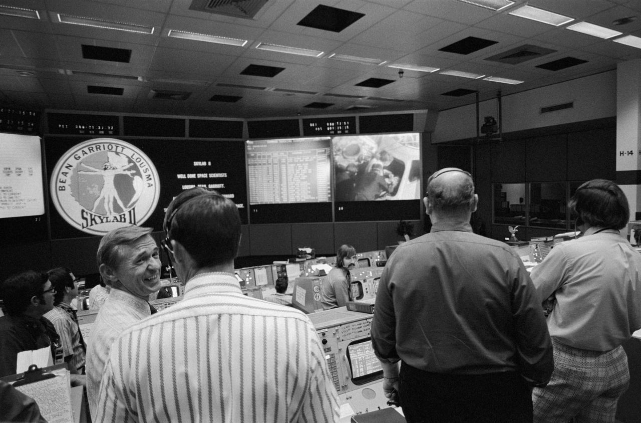
S73-34553 (25 Sept. 1973) --- Skylab flight directors (foreground) and flight controllers (background) view the large screen in the Mission Operations Control Room (MOCR) in the Mission Control Center (MCC) at JSC during recovery operations of the second manned Skylab mission. From left to right in the foreground are flight directors Charles R. Lewis, Donald R. Puffy, Phillip Shaffer and Neil B. Hutchinson. The Skylab 3 crewmen were preparing to egress the spacecraft aboard the USS New Orleans. Television cameras aboard the New Orleans recorded post-recovery activity. Photo credit: NASA
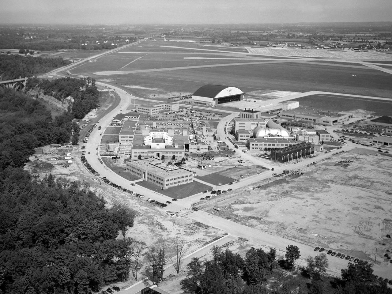
The National Advisory Committee for Aeronautics (NACA) Lewis Flight Propulsion Laboratory in Cleveland, Ohio as seen from the west in May 1946. The Cleveland Municipal Airport is located directly behind. The laboratory was built in the early 1940s to resolve problems associated with aircraft engines. The initial campus contained seven principal buildings: the Engine Research Building, hangar, Fuels and Lubricants Building, Administration Building, Engine Propeller Research Building, Altitude Wind Tunnel, and Icing Research Tunnel. These facilities and their associated support structures were located within an area occupying approximately one-third of the NACA’s property. After World War II ended, the NACA began adding new facilities to address different problems associated with the newer, more powerful engines and high speed flight. Between 1946 and 1955, four new world-class test facilities were built: the 8- by 6-Foot Supersonic Wind Tunnel, the Propulsion Systems Laboratory, the Rocket Engine Test Facility, and the 10- by 10-Foot Supersonic Wind Tunnel. These large facilities occupied the remainder of the NACA’s semicircular property. The Lewis laboratory expanded again in the late 1950s and early 1960s as the space program commenced. Lewis purchased additional land in areas adjacent to the original laboratory and acquired a large 9000-acre site located 60 miles to the west in Sandusky, Ohio. The new site became known as Plum Brook Station.
Engineers at the National Aeronautics and Space Administration (NASA) Lewis Research Center inspect the nitrogen baffle in the interior of the 22.5-foot diameter dome at the Space Power Chambers. In 1961 NASA Lewis management decided to convert the Altitude Wind Tunnel into two large test chambers and renamed the facility the Space Power Chambers. The conversion, which took over two years, included removing the tunnel’s drive fan, exhaust scoop, and turning vanes from the east end and inserting bulkheads to seal off the new chambers within the tunnel. The eastern section of the tunnel became a vacuum chamber capable of simulating 100 miles altitude. In 1962 NASA management decided to use the new vacuum chamber exclusively to study the second-stage rocket. This required significant modifications to the new tank and extensive test equipment to create a space environment. The Lewis test engineers sought to subject the Centaur to long durations in conditions that would replicate those encountered during its missions in space. The chamber was already capable of creating the vacuum of space, but the test engineers also wanted to simulate the cryogenic temperatures and solar radiation found in space. Six panels of 500-watt tungsten-iodine lamps were arranged around the Centaur to simulate the effect of the Sun’s heat. A large copper cold wall with its interior coated with heat-absorbing black paint was created specifically for these tests and assembled around the Centaur. The 42-foot-high wall had vertical ribs filled with liquid nitrogen which produced the low temperatures.
Abe Silverstein, Associate Director of the National Advisory Committee for Aeronautics (NACA) Lewis Flight Propulsion Laboratory, provides a personal tour of the new 10- by 10-Foot Supersonic Wind Tunnel for US Senator George Bender (hat in hand) and General Lemuel Shepherd. Shepherd was Commandant of the Marine Corps and had served in World War I, World War II, and the Korean War. The general was accompanied by Admiral Herbert Leary, in dark uniform. Bender was a Republican Senator from Ohio. Behind Bender is President of the Cleveland Chamber of Commerce Curtis Smith. NACA Lewis managers Eugene Manganiello and Wilson Hunter assist with the tour. Abe Silverstein oversaw all research at the laboratory. Upon taking his post in 1952 he reorganized the research staff and began shifting the focus away from airbreathing aircraft engines to new fields such as high energy fuels, electric propulsion, and nuclear power and propulsion. He was an early advocate of the NACA’s involvement in the space program and crucial to the founding of National Aeronautics and Space Administration in 1958. Silverstein began his career helping design and conduct research in the Full Scale Tunnel in 1929 at the Langley Memorial Aeronautical Laboratory. Silverstein advocated a series of increasingly large supersonic wind tunnels after the war, culminating in the 10- by 10.
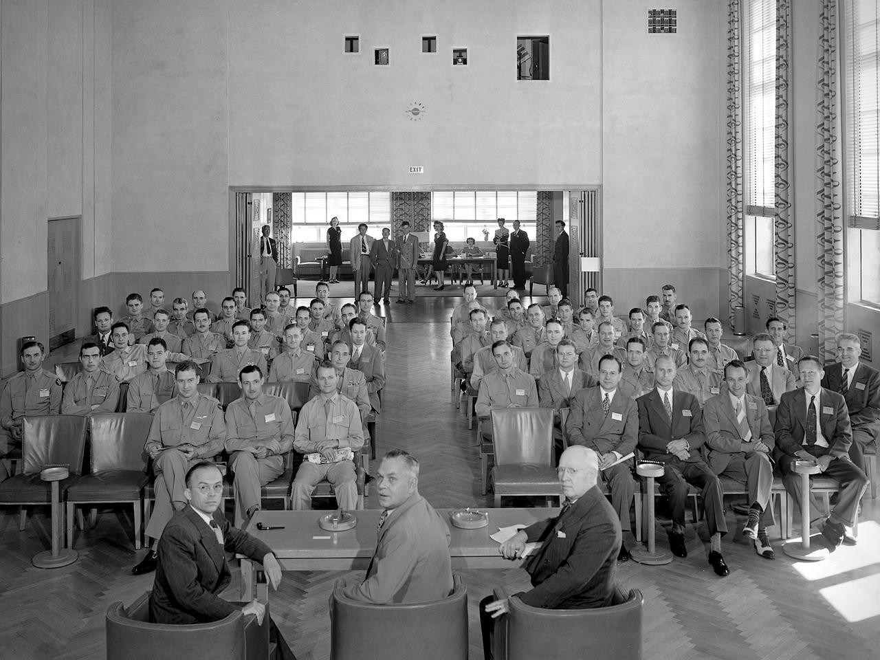
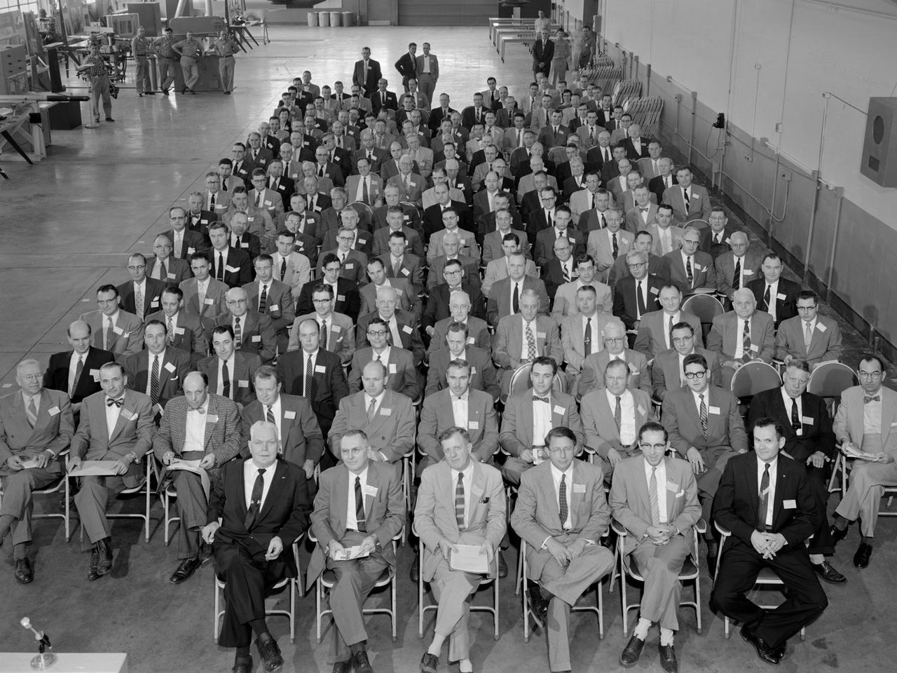
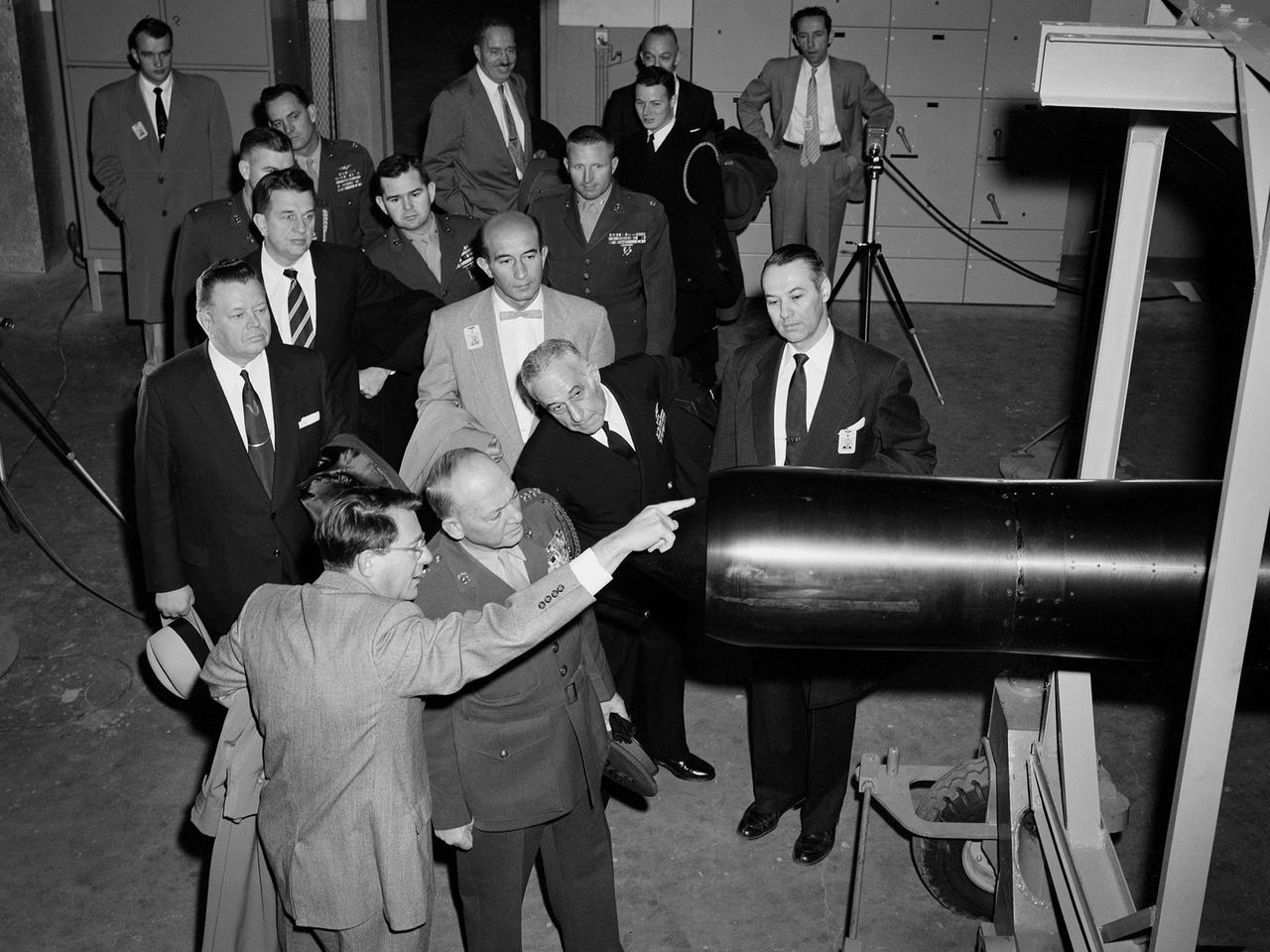
A group of 60 Army Air Forces officers visited the National Advisory Committee for Aeronautics (NACA) Aircraft Engine Research Laboratory on August 27, 1945. The laboratory enacted strict security regulations throughout World War II. During the final months of the war, however, the NACA began opening its doors to groups of writers, servicemen, and aviation industry leaders. These events were the first exposure of the new engine laboratory to the outside world. Grandstands were built alongside the Altitude Wind Tunnel specifically for group photographs. George Lewis, Raymond Sharp, and Addison Rothrock (right to left) addressed this group of officers in the Administration Building auditorium. Lewis was the NACA’s Director of Aeronautical Research, Sharp was the lab’s manager, and Rothrock was the lab’s chief of research. Abe Silverstein, Jesse Hall and others watch from the rear of the room. The group toured several facilities after the talks, including the Altitude Wind Tunnel and a new small supersonic wind tunnel. The visit concluded with a NACA versus Army baseball game and cookout.

New staff member Paul Margosian inspects a cluster of ion engines in the Electric Propulsion Laboratory’s 25-foot diameter vacuum tank at the National Aeronautics and Space Administration (NASA) Lewis Research Center. Lewis researchers had been studying different methods of electric rocket propulsion since the mid-1950s. Harold Kaufman created the first successful engine, the electron bombardment ion engine, in the early 1960s. These engines used electric power to create and accelerate small particles of propellant material to high exhaust velocities. Electric engines have a very small thrust, and but can operate for long periods of time. The ion engines are often clustered together to provide higher levels of thrust. The Electric Propulsion Laboratory contained two large vacuum tanks capable of simulating the space environment. The tanks were designed especially for testing ion and plasma thrusters and spacecraft. The larger 25-foot diameter tank was intended for testing electric thrusters with condensable propellants. The tank’s test compartment, seen here, was 10 feet in diameter. Margosian joined Lewis in late 1962 during a major NASA hiring phase. The Agency reorganized in 1961 and began expanding its ranks through a massive recruiting effort. Lewis personnel increased from approximately 2,700 in 1961 to over 4,800 in 1966. Margosian, who worked with Bill Kerslake in the Electromagnetic Propulsion Division’s Propulsion Systems Section, wrote eight technical reports on mercury and electron bombardment thrusters, thermoelectrostatic generators, and a high voltage insulator.
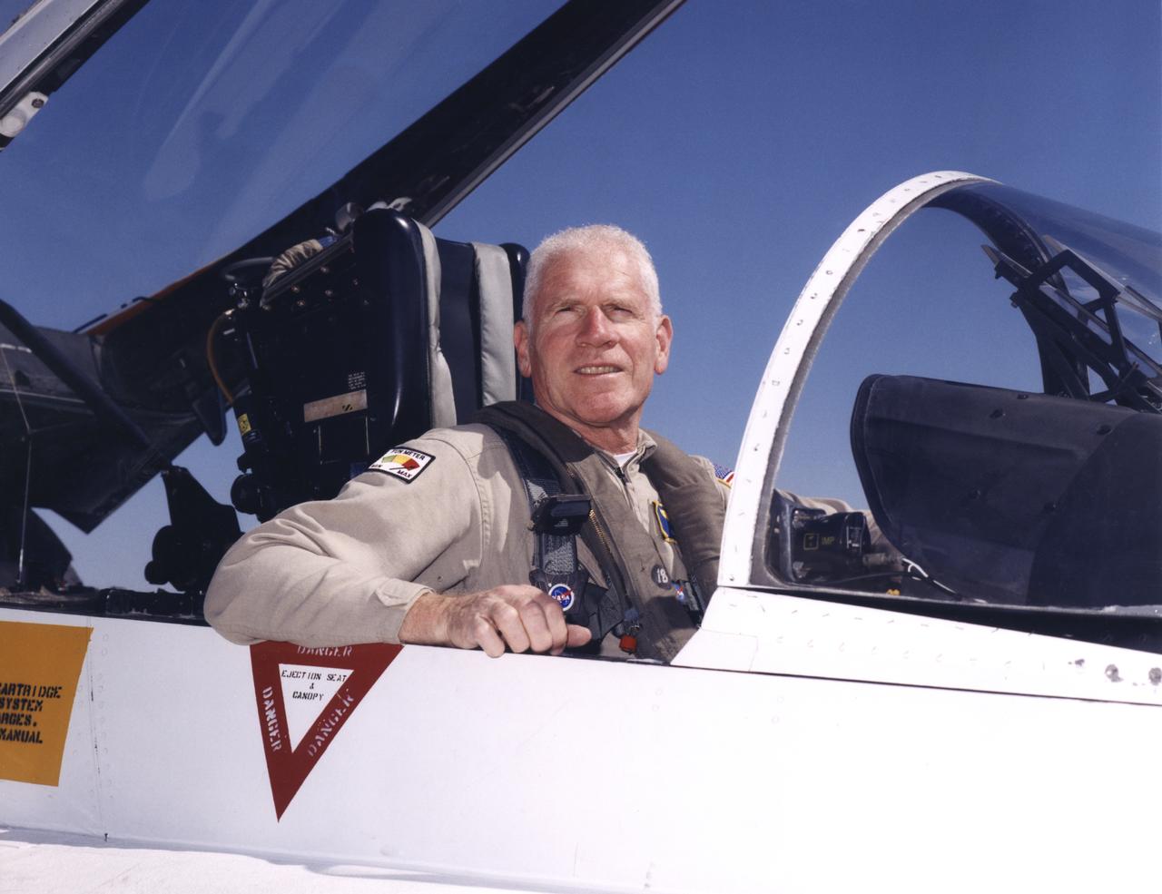
Edwin W. Lewis Jr. is a research pilot in the Airborne Science program, Flight Crew Branch, Dryden Flight Research Center, Edwards, California. He currently flies the DC-8, F/A-18, Lear Jet 24, King Air, and T-34C in support of Dryden's flight operations and is mentor pilot for the King Air and the Lear Jet. Prior to accepting this assignment Lewis was a pilot for eight years at NASA's Ames Research Center, Moffett Field, California, flying 10 different aircraft C-130B, DC-8-72, UH-1, SH-3, King Air, Lear 24, T-38A, T-39G and YO-3A in support of NASA flight missions. Lewis also flew the Kuiper Airborne Observatory (a modified civilian version of the Lockheed C-141 Starlifter). He was project pilot for Ames' 747 and T-38 programs. Lewis was born in New York City on May 19, 1936, and began flight training as a Civil Air Patrol cadet in 1951, ultimately earning his commercial pilot's certificate in 1958. He received a bachelor of arts degree in biology from Hobart College, Geneva, N.Y., and entered the U.S. Air Force through the Reserve Officer Training Corps. Following pilot training he was assigned to Moody Air Force Base, Ga., as an instructor pilot, for both the T-33 and T-37 aircraft. He served in Vietnam in 1965 and 1966, where he was a forward air controller, instructor and standardization/evaluation pilot, flying more than 1,000 hours in the O-1 "Bird Dog." Lewis separated from the regular Air Force and joined Pan American World Airways and the 129th Air Commando Group, California Air National Guard (ANG) based in Hayward, California. During his 18-year career with the California ANG he flew the U-6, U-10, C-119, HC-130 aircraft and the HH-3 helicopter. He retired as commander, 129th Air Rescue and Recovery Group, a composite combat rescue group, in the grade of colonel. During his 22 years as an airline pilot, he flew the Boeing 707, 727 and 747. He took early retirement from Pan American in 1989 to become a pilot with NASA.

A Mod-1 2000-kilowatt wind turbine designed by National Aeronautics and Space Administration (NASA) Lewis Research Center and constructed in Boone, North Carolina. The wind turbine program was a joint program between NASA and the Energy Research and Development Administration (ERDA) during the 1970s to develop less expensive forms of energy. NASA Lewis was assigned the responsibility of developing large horizontal-axis wind turbines. The program included a series of increasingly powerful wind turbines, designated: Mod-0A, Mod-1, WTS-4, and Mod-5. The program’s first device was a Mod-0 100-kilowatt wind turbine test bed at NASA’s Plum Brook Station. There were four Mod-0A 200-kilowatt turbines built in New Mexico, Hawaii, Puerto Rico, and Rhode Island. The 2000-kilowatt wind turbine in North Carolina, seen here, was the only Mod-1 machine constructed. The two-bladed, 200-foot diameter device was built in May 1979 and began operation that September. The Mod-1 turbine performed exceedingly well and was fully integrated into the local power grid. NASA researchers also used the North Carolina device to study its effect on noise and television transmission.

A Mod-0A 200-kilowatt wind turbine designed by National Aeronautics and Space Administration (NASA) Lewis Research Center and constructed in Block Island, Rhode Island. The wind turbine program was a joint program between NASA and the Energy Research and Development Administration (ERDA) during the 1970s to develop less expensive forms of energy. NASA Lewis was assigned the responsibility of developing large horizontal-axis wind turbines. The program included a series of increasingly powerful wind turbines, designated: Mod-0A, Mod-1, WTS-4, and Mod-5. The program’s first device was a Mod-0 100-kilowatt wind turbine test bed at NASA’s Plum Brook Station. This Mod-0A 200-kilowatt turbine, completed in 1977, was the program’s second-generation device. It included a 125-foot diameter blade atop a 100-foot tall tower. This early wind turbine was designed determine its operating problems, integrate with the local utilities, and assess the attitude of the local community. There were additional Mod-0A turbines built in Culebra, Puerto Rico; Clayton, New Mexico; and Oahu, Hawaii. The Mod-0A turbines suffered durability issues with the rotor blade and initially appeared unreliable. NASA engineers addressed the problems, and the turbines proved to be reliable and efficient devices that operated for a number of years. The information gained from these early models was vital to the design and improvement of the later generations.
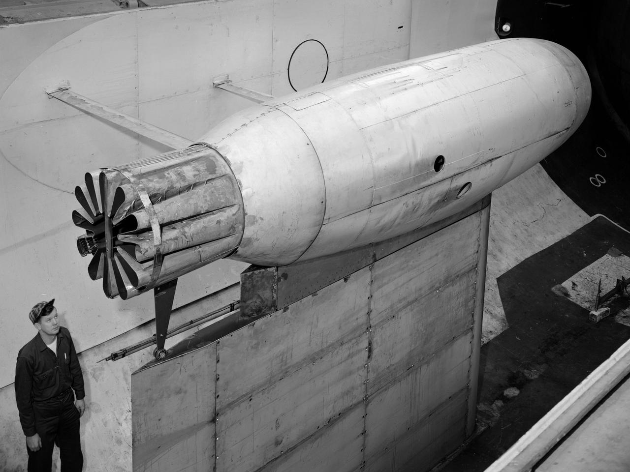
A Pratt and Whitney J57 engine is tested with a Greatex No.1 nozzle in the Altitude Wind Tunnel at the National Advisory Committee for Aeronautics (NACA) Lewis Flight Propulsion Laboratory. At the time the aircraft industry was preparing to introduce jet airliners to the nation’s airways. The noise produced by the large jet engines, however, posed a considerable problem for communities near airports. The NACA had formed a Special Subcommittee on Aircraft Noise to coordinate research on the issue. Preliminary tests showed that the source of the loudest noise was not the engine itself, but the mixing of the engine’s exhaust with the surrounding air in the atmosphere. The pressures resulting from this turbulence produced sound waves. Lewis researchers undertook a variety of noise-reduction studies involving engine design, throttling procedures, and noise suppressors. One of their first efforts focused on new types of nozzles to mix the exhaust with the surrounding air. The nozzles had a variety of shapes designed to slow down exhaust velocity before it combined with the air and thus decrease the noise. From January to May 1957 a Pratt and Whitney J57 engine was equipped with various shaped nozzles, as seen in this photograph, and run in simulated flight conditions in the Altitude Wind Tunnel. A number of nozzle configurations, including several multi-exit “organ pipe” designs, were created. It was found that the various nozzle types did reduce the noise levels, but they also reduced the aircraft’s thrust.
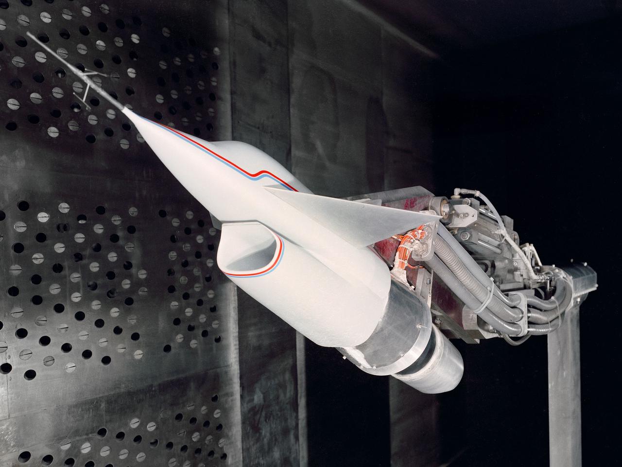
A Highly Maneuverable Aircraft Technology (HiMAT) inlet model installed in the test section of the 8- by 6-Foot Supersonic Wind Tunnel at the National Aeronautics and Space Administration (NASA) Lewis Research Center. Engineers at the Ames Research Center, Dryden Flight Research Center, and Rockwell International designed two pilotless subscale HiMAT vehicles in the mid-1970s to study new design concepts for fighter aircraft in the transonic realm without risking the lives of test pilots. The aircraft used sophisticated technologies such as advanced aerodynamics, composite materials, digital integrated propulsion control, and digital fly-by-wire control systems. In late 1977 NASA Lewis studied the HiMAT’s General Electric J85-21 jet engine in the Propulsion Systems Laboratory. The researchers charted the inlet quality with various combinations anti-distortion screens. HiMAT employed a relatively short and curved inlet compared to actual fighter jets. In the spring of 1979, Larry Smith led an in-depth analysis of the HiMAT inlet in the 8- by 6 tunnel. The researchers installed vortex generators to battle flow separation in the diffuser. The two HiMAT aircraft performed 11 hours of flying over the course of 26 missions from mid-1979 to January 1983 at Dryden and Ames. Although the HiMAT vehicles were considered to be overly complex and expensive, the program yielded a wealth of data that would validate computer-based design tools.
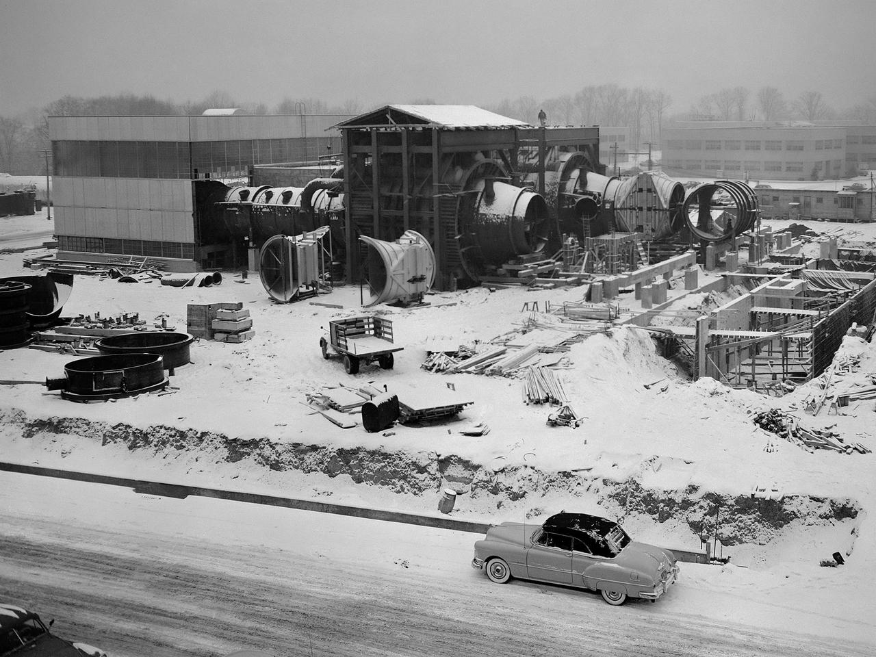
Construction of the Propulsion Systems Laboratory No. 1 and 2 at the National Advisory Committee for Aeronautics (NACA) Lewis Flight Propulsion Laboratory. When it began operation in late 1952, the Propulsion Systems Laboratory was the NACA’s most powerful facility for testing full-scale engines at simulated flight altitudes. The facility contained two altitude simulating test chambers which were a technological combination of the static sea-level test stands and the complex Altitude Wind Tunnel, which recreated actual flight conditions on a larger scale. NACA Lewis began designing the new facility in 1947 as part of a comprehensive plan to improve the altitude testing capabilities across the lab. The exhaust, refrigeration, and combustion air systems from all the major test facilities were linked. In this way, different facilities could be used to complement the capabilities of one another. Propulsion Systems Laboratory construction began in late summer 1949 with the installation of an overhead exhaust pipe connecting the facility to the Altitude Wind Tunnel and Engine Research Building. The large test section pieces arriving in early 1951, when this photograph was taken. The two primary coolers for the altitude exhaust are in place within the framework near the center of the photograph.
From left, Marie Lewis, NASA Communications; and Thomas Zurbuchen, associate administrator, NASA’s Science Mission Directorate, speak to members of the news media during a prelaunch news conference for NASA’s Landsat 9 mission at Vandenberg Space Force Station in California on Sept. 25, 2021. Landsat 9 is scheduled to launch at 2:12 p.m. EDT (11:12 a.m. PDT) on Monday, Sept. 27, on a United Launch Alliance Atlas V 401 rocket from Space Launch Complex 3 at Vandenberg. The launch is managed by NASA’s Launch Services Program, based at the agency’s Kennedy Space Center in Florida. Landsat 9 will join its sister satellite, Landsat 8, in orbit in collecting images from across the planet every eight days. This calibrated data will continue the Landsat program’s critical role in monitoring the health of Earth and helping people manage essential resources, including crops, irrigation water, and forests.
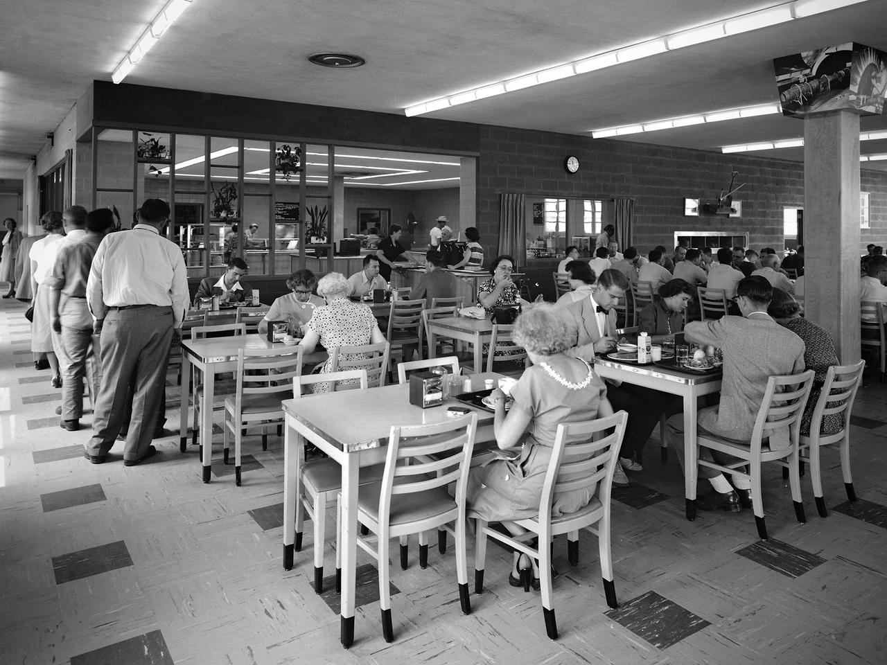
NACA staff members queue up in the Lewis Flight Propulsion Laboratory cafeteria in August 1952. The cafeteria originally opened in November 1942 inside the south end of the Engine Research Building. A non-profit Exchange was established to handle the finances, while Helen Thompson, a German born pastry cook, ran the day-to-day operations. Employees could also purchase her bakery to take home with them. Services were expanded to include a lunch counter and a food cart that ferried meals to the facilities. By the end of World War II the cafeteria was serving nearly 1600 meals daily in a space designed for half of that. In 1951 a new wing was added to the Utilities Building to accommodate an expanded cafeteria, seen in this photograph. In the mid-1960s an auxiliary unit was built in the new Development Engineering Building located across Brookpark Road.
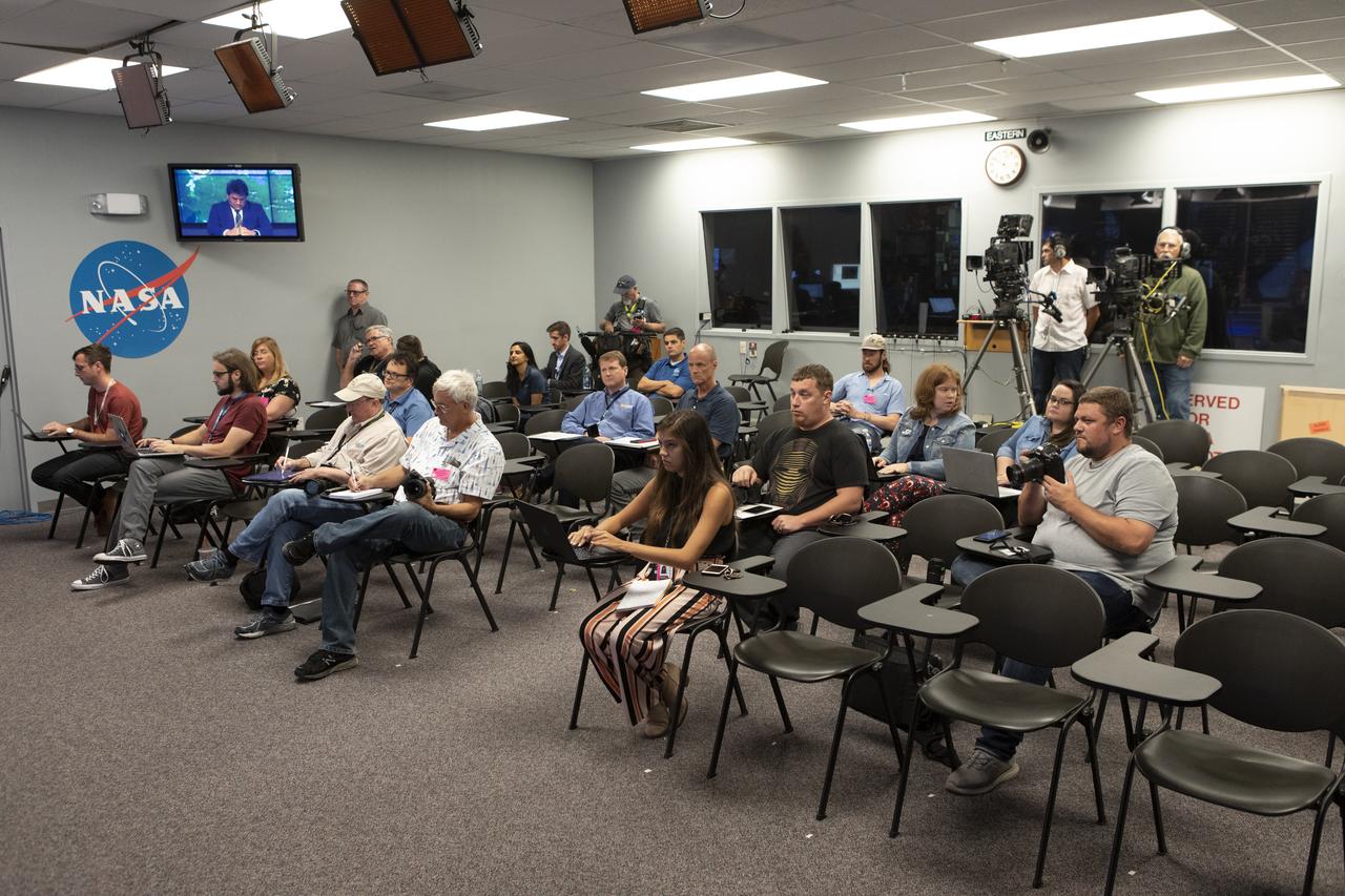
Members of the news media attend the prelaunch news conference for SpaceX’s 18th Commercial Resupply Services (CRS-18) mission to the International Space Station, July 24, 2019, at NASA’s Kennedy Space Center in Florida. Participants were Marie Lewis, NASA Communications moderator; Bill Spetch, deputy manager of the International Space Station Transportation Integration Office at the agency’s Johnson Space Center in Houston; Jessica Jensen, director of Dragon mission management at SpaceX; Pete Hasbrook, manager of the space station’s Program Science Office at Johnson; and Will Ulrich, launch weather officer with the U.S. Air Force 45th Space Wing. The SpaceX Falcon 9 rocket and uncrewed Dragon spacecraft are scheduled to launch July 24, 2019, from Space Launch Complex 40 at Florida’s Cape Canaveral Air Force Station.
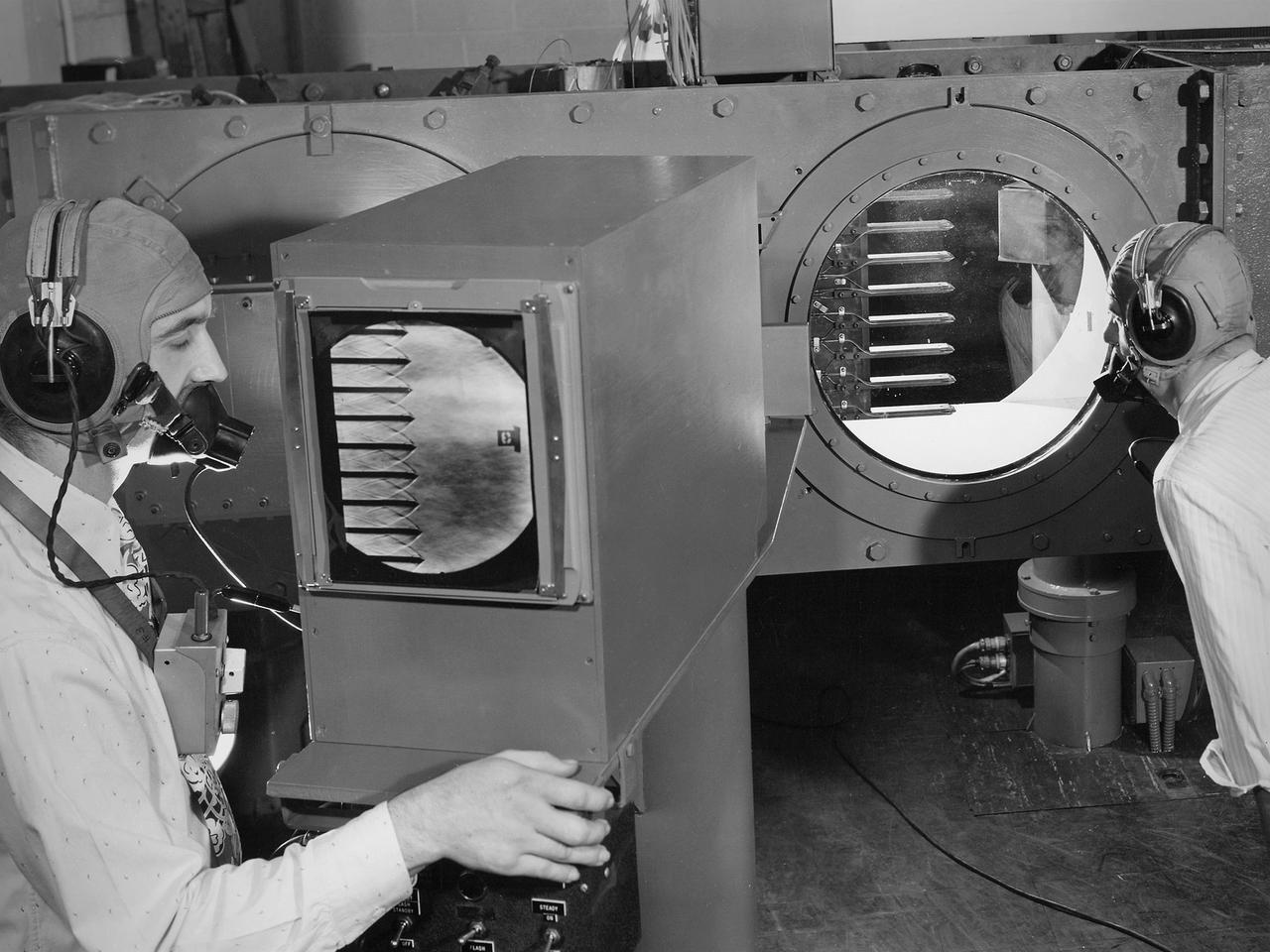
Engineers calibrate one of three small supersonic wind tunnels that were collectively referred to as the “Stack Tunnels” at the National Advisory Committee for Aeronautics (NACA) Lewis Flight Propulsion Laboratory. In late 1945 NACA Lewis reorganized its staff and began constructing a new wave of facilities to address high-speed flight and the turbojet and rocket technologies that emerged during World War II. While design work began on what would eventually become the 8- by 6-Foot Supersonic Wind Tunnel, NACA Lewis quickly built several small supersonic tunnels. These small facilities utilized the Altitude Wind Tunnel’s massive air handling equipment. Three of the small tunnels were built vertically on top of each other and thus were known as the Stack Tunnels. The first of the Stack Tunnels was an 18- by 18-inch tunnel that began operating in August 1945 at speeds up to Mach 1.91. The second tunnel, whose 24- by 24-inch test section is shown here, was added in 1949. It could generate air flows up to Mach 3.96. A third tunnel with an 18- by 18-inch test section began operating in 1951 with speeds up to Mach 3.05. The small tunnels were used until the early 1960s to study the aerodynamic characteristics of supersonic inlets and exits. The technician to the left in this photograph is operating a Schlieren camera to view the air flow dynamics inside the 24- by 24-inch test section. The technician on the right is viewing the pronged test article through the circular window. They are calibrating the tunnel and its equipment to prepare for the initial test runs.
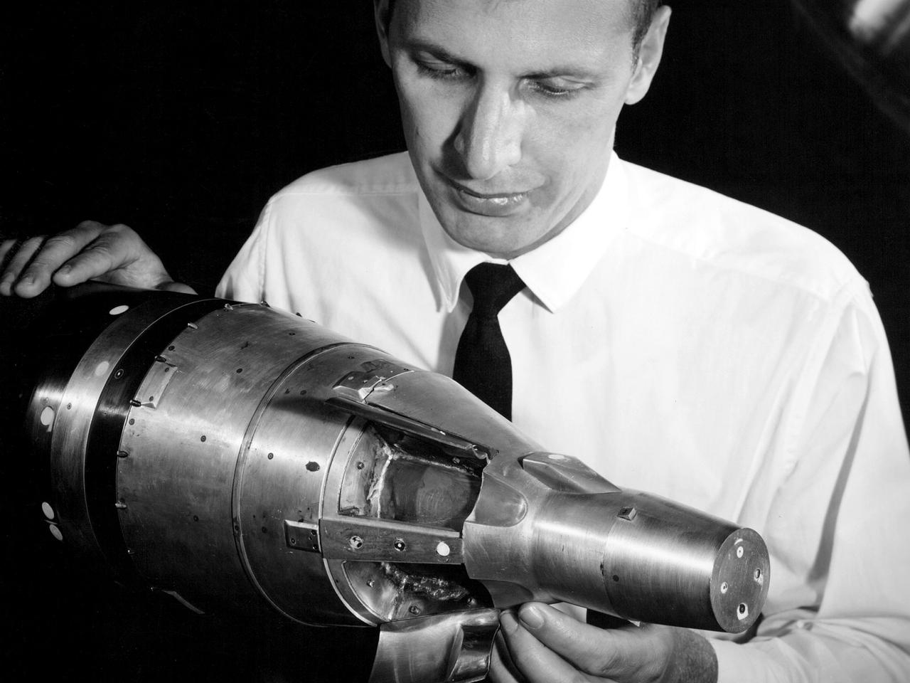
A researcher at the National Aeronautics and Space Administration (NASA) Lewis Research Center examines a small-scale model of the Gemini capsule in the 10- by 10-Foot Supersonic Wind Tunnel test section. Gemini was added to NASA’s manned space program after its predecessor, Mercury, and its antecedent, Apollo, were already established. Gemini was a transitional mission designed provide the astronauts with practice docking with other spacecraft and withstanding durations in space up to two weeks. The program was officially announced on December 7, 1961, but planning began in mid-1959. It was named Gemini after the zodiac twins because of the spacecraft’s two passenger capacity. The Gemini Program was the first program to start at the new Manned Spacecraft Center in Houston, now the Johnson Space Center. Unlike Mercury and Apollo, Lewis had very little involvement with the Gemini Program. This model was tested in the 10- by 10 tunnel for several weeks in September 1962. Lewis began managing the Agena second-stage rocket program shortly after this photograph was taken. Agenas were used to launch a variety of spacecraft and satellites in the 1960s. They were also used on several Gemini missions to provide targets for the astronauts to practice their rendezvous maneuvers. Gemini had two unmanned and ten manned flights in 1965 and 1966. These yielded the first spacewalks, long-duration space missions, first onboard computer, docking with a second spacecraft, and rendezvous maneuvers.
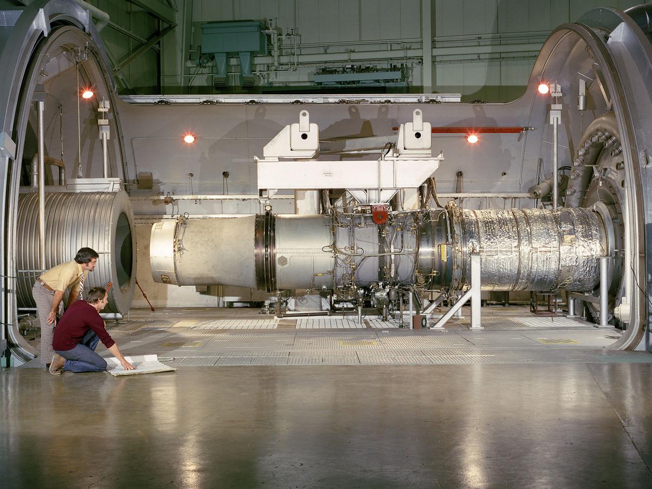
A refanned Pratt and Whitney JT-8D-109 turbofan engine installed in Cell 4 of the Propulsion Systems Laboratory at the National Aeronautics and Space Administration (NASA) Lewis Research Center. NASA Lewis’ Refan Program sought to demonstrate that noise reduction modifications could be applied to existing aircraft engines with minimal costs and without diminishing the engine’s performance or integrity. At the time, Pratt and Whitney’s JT-8D turbofans were one of the most widely used engines in the commercial airline industry. The engines powered Boeing’s 727 and 737 and McDonnell Douglas’ DC-9 aircraft. Pratt and Whitney worked with the airline manufacturers on a preliminary study that verified feasibility of replacing the JT-8D’s two-stage fan with a larger single-stage fan. The new fan slowed the engine’s exhaust, which significantly reduced the amount of noise it generated. Booster stages were added to maintain the proper level of airflow through the engine. Pratt and Whitney produced six of the modified engines, designated JT-8D-109, and performed the initial testing. One of the JT-8D-109 engines, seen here, was tested in simulated altitude conditions in NASA Lewis’ Propulsion Systems Laboratory. The Refan engine was ground-tested on an actual aircraft before making a series of flight tests on 727 and DC-9 aircraft in early 1976. The Refan Program reduced the JT-8D’s noise by 50 percent while increasing the fuel efficiency. The retro-fit kits were estimated to cost between $1 million and $1.7 million per aircraft.
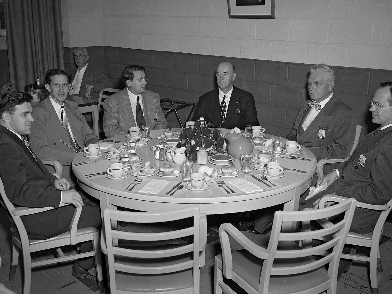
Dr. Igor Sikorsky, fourth from the left, visits the National Advisory Committee for Aeronautics (NACA) Lewis Flight Propulsion Laboratory in Cleveland, Ohio. The legendary Russian-born aviation pioneer visited NACA Lewis several times during the 1940s and 1950s. In 1946 Sikorsky arrived at Lewis for the 1946 National Air Races, which included demonstrations by five of his helicopters. NACA flight mechanic Joseph Sikosky personally escorted Sikorsky during the visit. Sikorsky frequently addressed local professional organizations, such as the American Society of Mechanical Engineers, during his visits. Sikorsky built and flew the first multi-engine aircraft as a youth in Russia. In his mid-20s Sikorsky designed and oversaw the manufacturing of 75 four-engine bombers. During the Bolshevik Revolution he fled to New York City where he worked jobs outside of aviation. In 1923 Sikorsky obtained funding to build a twin-engine water aircraft. This aircraft was the first US twin-engine flying machine and a world-wide success. In 1939 Sikorsky designed the first successful US helicopter. He then put all of his efforts into helicopters, and built some of the most successful helicopters in use today. Sikorsky passed away in 1972. From left to right: unknown; John Collins, Chief of the Engine Performance and Materials Division; Abe Silverstein, Chief of Research; Sikorsky; lab Director Ray Sharp; and Executive Officer Robert Sessions.
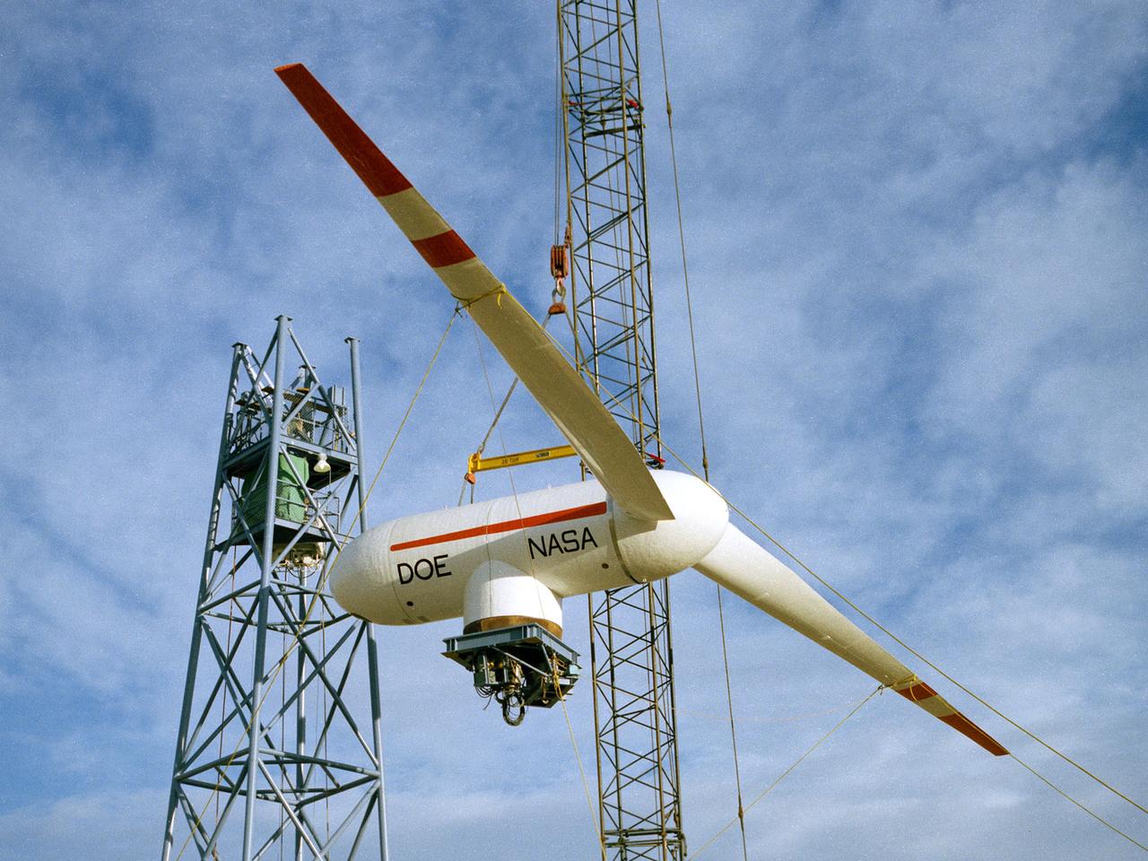
TA Mod-0A 200-kilowatt wind turbine designed by National Aeronautics and Space Administration (NASA) Lewis Research Center and constructed in Clayton, New Mexico. The wind turbine program was a joint effort by NASA and the Energy Research and Development Administration (ERDA) during the 1970s to develop less expensive forms of energy. NASA Lewis was assigned the responsibility of developing large horizontal-axis wind turbines. The program included a series of increasingly powerful wind turbines, designated: Mod-0A, Mod-1, WTS-4, and Mod-5. The program’s first device was a Mod-0 100-kilowatt wind turbine test bed built at NASA’s Plum Brook Station. This Mod-0A 200-kilowatt turbine built in Clayton in 1977 was the program’s second device. It included a 125-foot long blade atop a 100-foot tall tower. The Mod-0A was designed to determine the turbine’s operating problems, integrate the system with the local utilities, and assess the attitude of the local community. There were additional Mod-0A turbines built in Culebra, Puerto Rico; Block Island, Rhode Island; and Oahu, Hawaii. The Mod-0A turbines were initially unreliable and suffered issues with the durability of the rotor blade. Lewis engineers addressed the problems, and the wind turbines proved to be reliable and efficient devices that operated for a number of years. The information gained from these early models was vital to the design and improvement of the later generations.

Researcher Bobby Sanders examines a 0.10-scale model of the Mariner-C shroud and Agena rocket in the 8- by 6-Foot Supersonic Wind Tunnel at the National Aeronautics and Space Administration (NASA) Lewis Research Center. Mariner-C and Mariner-D were identical spacecraft designed by the Jet Propulsion Laboratory to flyby Mars and photograph the Martian surface. The two Mariner spacecraft were launched by Atlas-Agena-D rockets. Lewis had taken over management of the Agena Program in October 1962. Lewis researchers investigated two different types of shrouds for the Mariner missions—an over-the-nose design and a backup pyrotechnic design. The new shroud was wider in diameter than the Agena rocket, so there was concern that this disparity might create air flow instability that could damage the shroud or destroy the vehicle. The tests in the 8- by 6 tunnel simulated launch speeds from Mach 0.56 to 1.96. Afterwards the Agena-Mariner-C model was studied in the 10- by 10-Foot Supersonic Wind Tunnel at speeds of Mach 2.0 to 3.5. Mariner-C was launched on November 4, 1964, but the payload shroud did not jettison properly and the spacecraft’s battery power did not function. The mission ended unsuccessfully two days later. Mariner-D was launched on November 28, 1964 and became the first successful mission to Mars. It was the first time a planet was photographed from space. Mariner-D’s 21 photographs revealed an inhospitable and barren landscape.
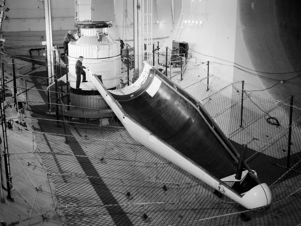
Researchers at the National Aeronautics and Space Administration (NASA) Lewis Research Center conducted a series of shroud jettison tests for the second Orbiting Astronomical Observatory (OAO-2) in the Space Power Chambers during April 1968. The Orbiting Astronomical Observatory satellites were designed by Goddard Space Flight Center to study and retrieve ultraviolet data on stars and galaxies which earthbound and atmospheric telescopes could not view due to ozone absorption. The shroud jettison system was tested in the Space Power Chambers. In 1961, NASA Lewis management decided to convert its Altitude Wind Tunnel into two large test chambers and later renamed it the Space Power Chambers. The conversion, which took over two years, included removing the tunnel’s internal components and inserting bulkheads to seal off the new chambers. The larger chamber, seen here, could simulate altitudes of 100,000 feet. These chambers were used for a variety of tests on the Centaur second-stage rocket until the early 1970s. The first OAO mission in 1965 failed due to problems with the satellite. OAO-2 would be launched on an Atlas/Centaur with a modified Agena shroud. The new shroud was 18 feet longer than the normal Centaur payload shrouds. This new piece of hardware was successfully qualified during three tests at 90,000 feet altitude in the Space Power Chambers in April 1968. For the first time, x-rays were used to verify the payload clearance once the shroud was sealed. OAO-2 was launched on December 7, 1968 and proved to be an extremely successful mission.
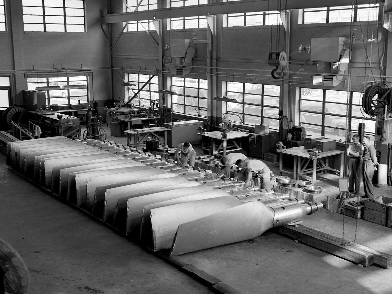
New wooden fan blades being prepared for installation in the Altitude Wind Tunnel at the National Advisory Committee for Aeronautics (NACA) Lewis Flight Propulsion Laboratory. The facility underwent a major upgrade in 1951 to increase its operating capacities in order to handle the new, more powerful turbojet engines being manufactured in the 1950s. The fan blades were prepared in the shop area, seen in this photograph, before being lowered through a hole in the tunnel and attached to the drive shaft. A new drive bearing and tail faring were also installed on the fan as part of this rehab project. A 12-bladed 31-foot-diameter spruce wood fan generated the 300 to 500 mile-per-hour airflow through the tunnel. An 18,000-horsepower General Electric induction motor located in the rear corner of the Exhauster Building drove the fan at 410 revolutions per minute. An extension shaft, sealed in the tunnel’s shell with flexible couplings that allowed for the movement of the shell, connected the motor to the fan. A bronze screen secured to the turning vanes protected the fan against damage from any engine parts sailing through the tunnel. Despite this screen the blades did become worn or cracked over time and had to be replaced.
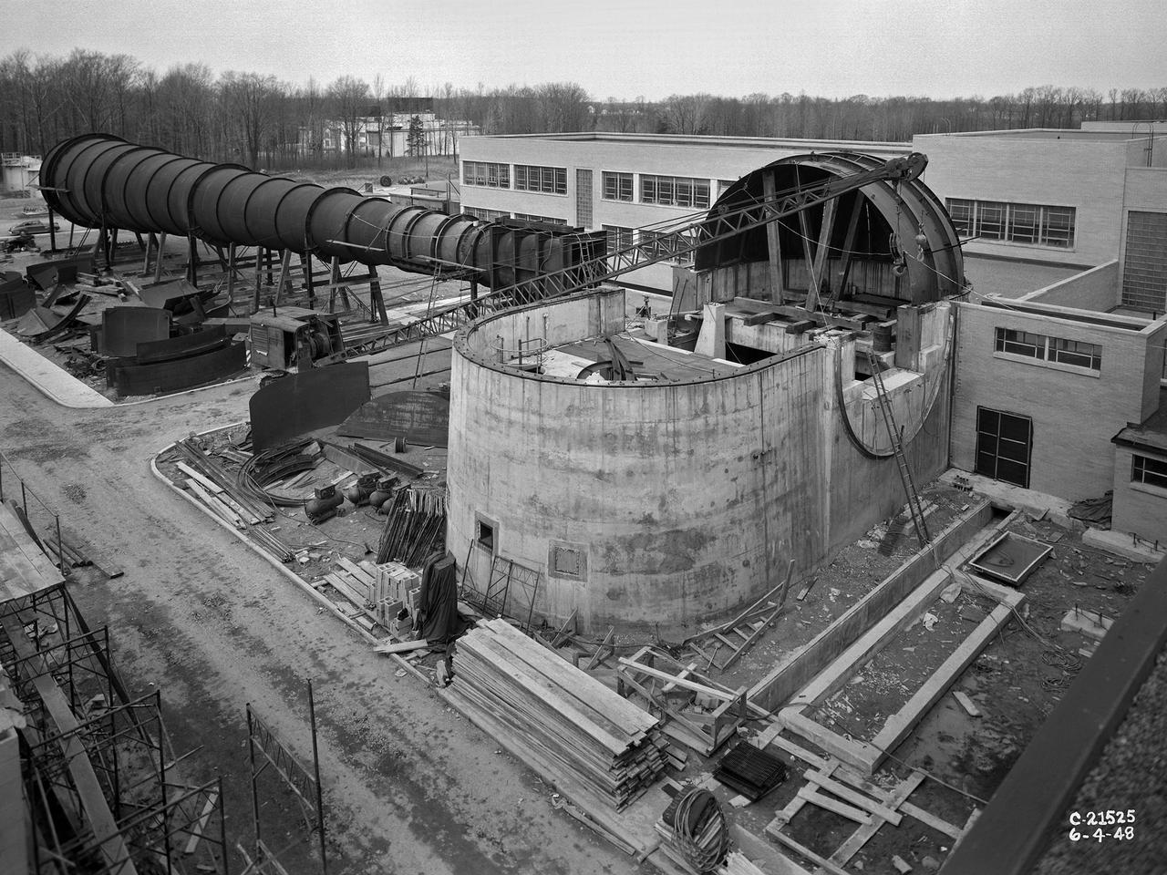
The 8- by 6-Foot Supersonic Wind Tunnel at the National Advisory Committee for Aeronautics (NACA) Lewis Flight Propulsion Laboratory was the nation’s largest supersonic facility when it began operation in April 1949. The emergence of new propulsion technologies such as turbojets, ramjets, and rockets during World War II forced the NACA and the aircraft industry to develop new research tools. In late 1945 the NACA began design work for new large supersonic wind tunnels at its three laboratories. The result was the 4- by 4-Foot Supersonic Wind Tunnel at Langley Memorial Aeronautical Laboratory, 6- by 6-foot supersonic wind tunnel at Ames Aeronautical Laboratory, and the largest facility, the 8- by 6-Foot Supersonic Wind Tunnel in Cleveland. The two former tunnels were to study aerodynamics, while the 8- by 6 facility was designed for supersonic propulsion. The 8- by 6-Foot Supersonic Wind Tunnel was used to study propulsion systems, including inlets and exit nozzles, combustion fuel injectors, flame holders, exit nozzles, and controls on ramjet and turbojet engines. Flexible sidewalls alter the tunnel’s nozzle shape to vary the Mach number during operation. A seven-stage axial compressor, driven by three electric motors that yield a total of 87,000 horsepower, generates air speeds from Mach 0.36 to 2.0. A section of the tunnel is seen being erected in this photograph.
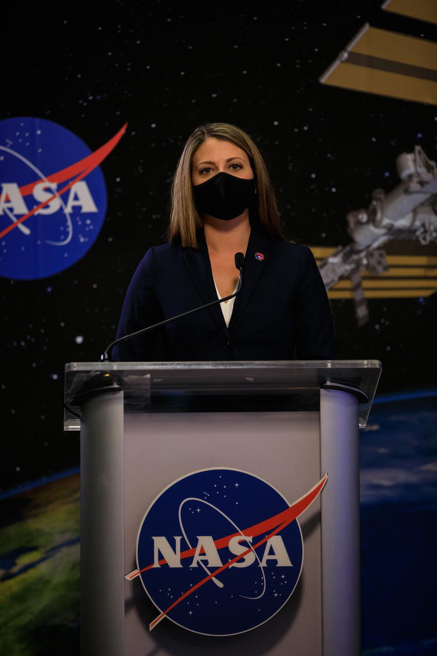
Marie Lewis, NASA Communications, moderates the SpaceX Crew-2 prelaunch news conference held at NASA’s Kennedy Space Center in Florida on April 20, 2021. Participants included: Steve Stich, manager, NASA Commercial Crew Program; Joel Montalbano, manager, International Space Station Program; Benji Reed, senior director, Human Spaceflight Programs, SpaceX; Norm Knight, deputy manager, Flight Operations Directorate; Junichi Sakai, manager, International Space Station Program, JAXA; Frank de Winne, manager, International Space Station Program, ESA; Kirt Costello, chief scientist, International Space Station Program; and Brian Cizek, launch weather officer, 45th Weather Squadron, U.S. Space Force.
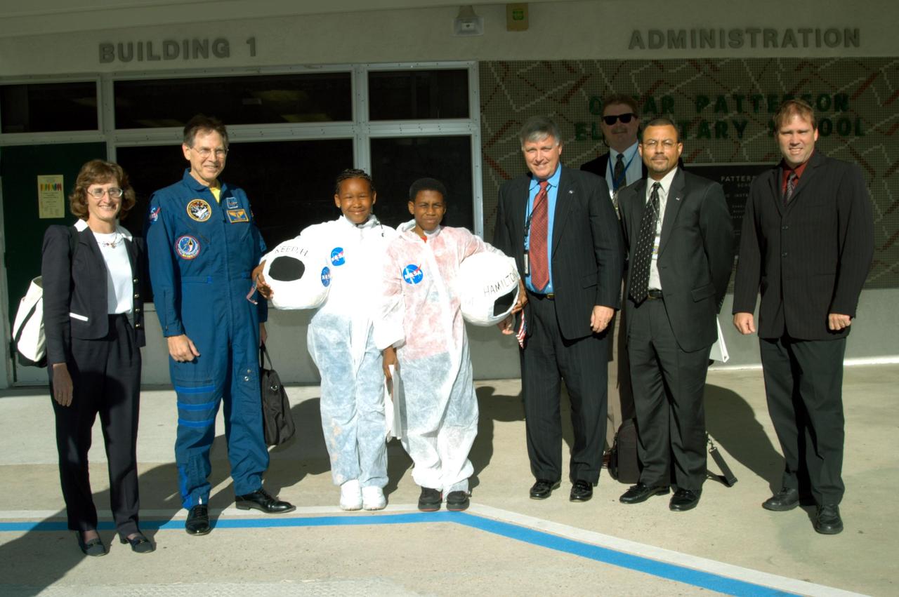
KENNEDY SPACE CENTER, FLA. -- NASA-KSC representatives pose with two students in front of Oscar Patterson Elementary Magnet School in Panama City, Fla. From left are Pam Biegert (chief of KSC’s Education Programs and University Research Office), astronaut Sam Durrance, Center Director Jim Kennedy, John Halsema (chief, Government Relations Office), Steve Lewis (assistant to Kennedy), and Mike Rein (division chief, Communications). NASA-KSC officials are visiting NASA Explorer Schools in Florida and Georgia to share America’s new vision for space exploration with the next generation of explorers. Kennedy is talking with students about our destiny as explorers, NASA’s stepping stone approach to exploring Earth, the Moon, Mars and beyond, how space impacts our lives, and how people and machines rely on each other in space.
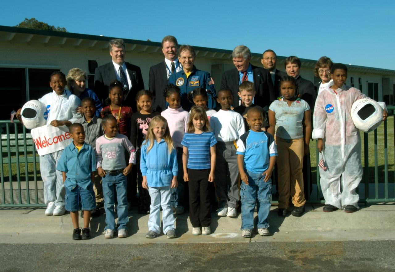
KENNEDY SPACE CENTER, FLA. -- Students at Oscar Patterson Elementary Magnet School in Panama City, Fla., gather for a photo with NASA representatives standing behind them. At center is astronaut Sam Durrance; on the right is Center Director Jim Kennedy; behind Durrance at left is John Halsema, chief in the Government Relations Office. Behind and right of Kennedy is Steve Lewis, his assistant. Behind the student on the far right is Pam Biegert, chief of KSC’s Education Programs and University Research Office. Kennedy is visiting NASA Explorer Schools in Florida and Georgia to share America’s new vision for space exploration with the next generation of explorers. Kennedy is talking with students about our destiny as explorers, NASA’s stepping stone approach to exploring Earth, the Moon, Mars and beyond, how space impacts our lives, and how people and machines rely on each other in space.
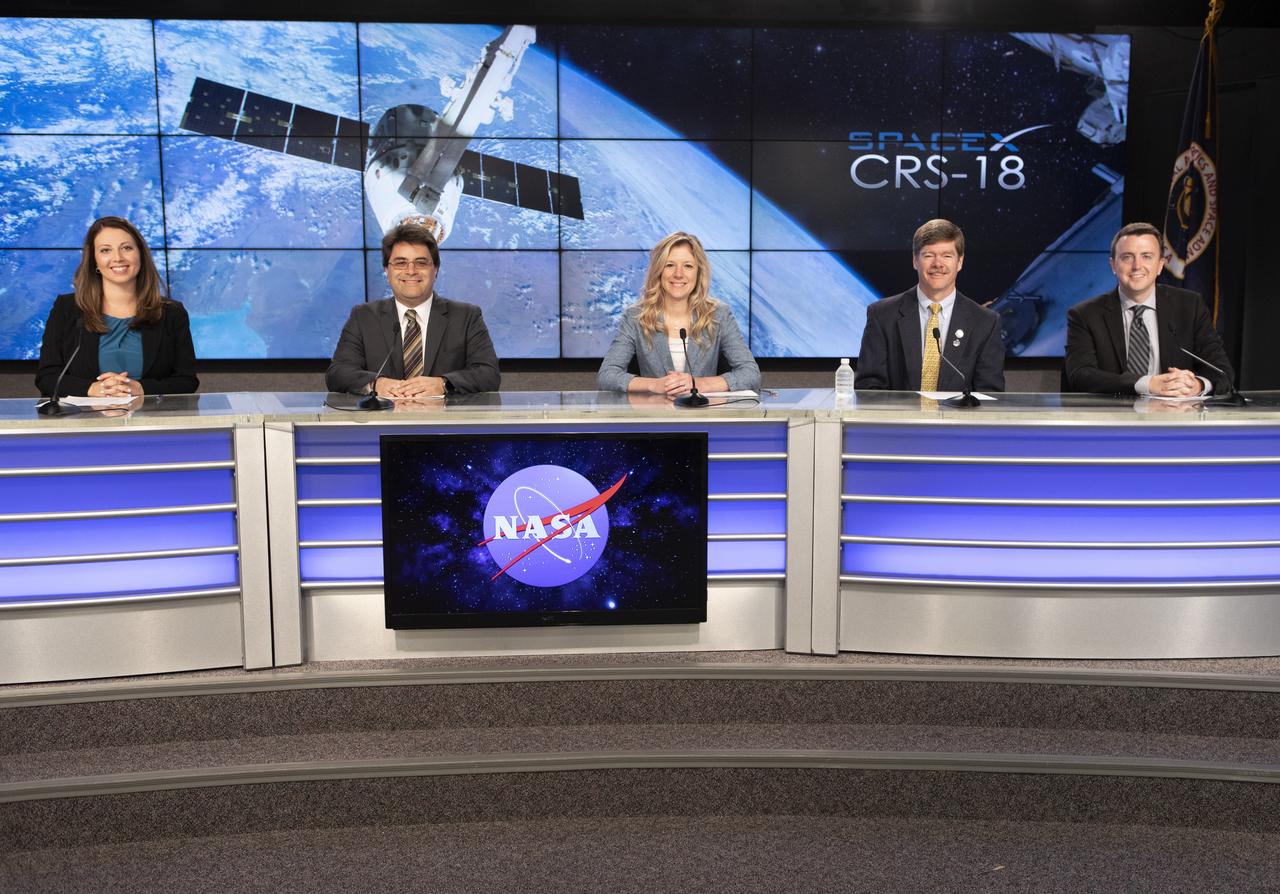
A prelaunch news conference for SpaceX’s 18th Commercial Resupply Services (CRS-18) mission to the International Space Station for NASA is held July 24, 2019, at the agency’s Kennedy Space Center in Florida. From left are Marie Lewis, NASA Communications moderator; Bill Spetch, deputy manager of the International Space Station Transportation Integration Office at NASA’s Johnson Space Center in Houston; Jessica Jensen, director of Dragon mission management at SpaceX; Pete Hasbrook, manager of the space station’s Program Science Office at Johnson; and Will Ulrich, launch weather officer with the U.S. Air Force 45th Space Wing. The SpaceX Falcon 9 rocket and uncrewed Dragon spacecraft are scheduled to launch July 24, 2019, from Space Launch Complex 40 at Florida’s Cape Canaveral Air Force Station.
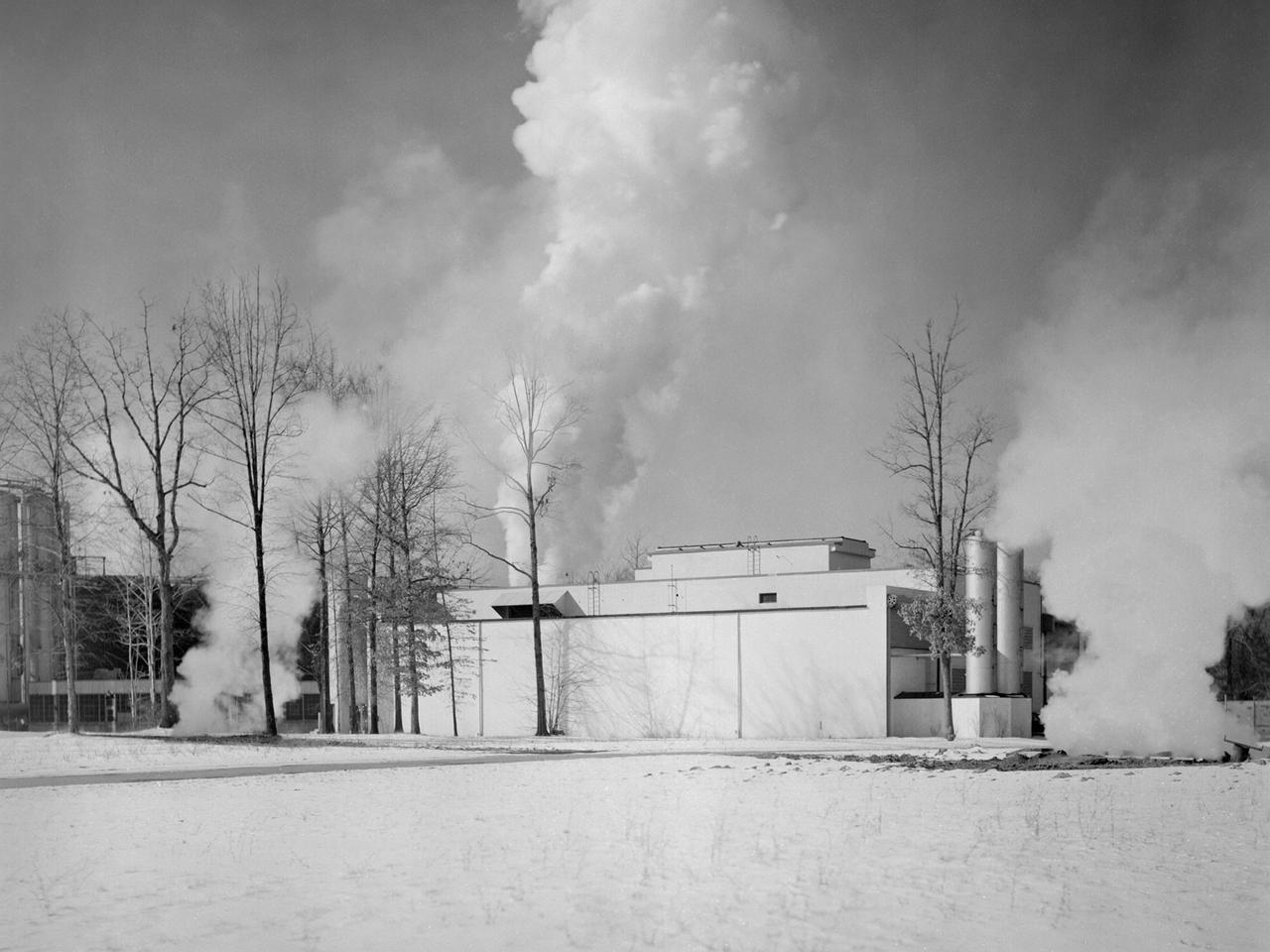
The Engine Propeller Research Building, referred to as the Prop House, emits steam from its acoustic silencers at the National Advisory Committee for Aeronautics (NACA) Lewis Flight Propulsion Laboratory. In 1942 the Prop House became the first completed test facility at the new NACA laboratory in Cleveland, Ohio. It contained four test cells designed to study large reciprocating engines. After World War II, the facility was modified to study turbojet engines. Two of the test cells were divided into smaller test chambers, resulting in a total of six engine stands. During this period the NACA Lewis Materials and Thermodynamics Division used four of the test cells to investigate jet engines constructed with alloys and other high temperature materials. The researchers operated the engines at higher temperatures to study stress, fatigue, rupture, and thermal shock. The Compressor and Turbine Division utilized another test cell to study a NACA-designed compressor installed on a full-scale engine. This design sought to increase engine thrust by increasing its airflow capacity. The higher stage pressure ratio resulted in a reduction of the number of required compressor stages. The last test cell was used at the time by the Engine Research Division to study the effect of high inlet densities on a jet engine. Within a couple years of this photograph the Prop House was significantly altered again. By 1960 the facility was renamed the Electric Propulsion Research Building to better describe its new role in electric propulsion.
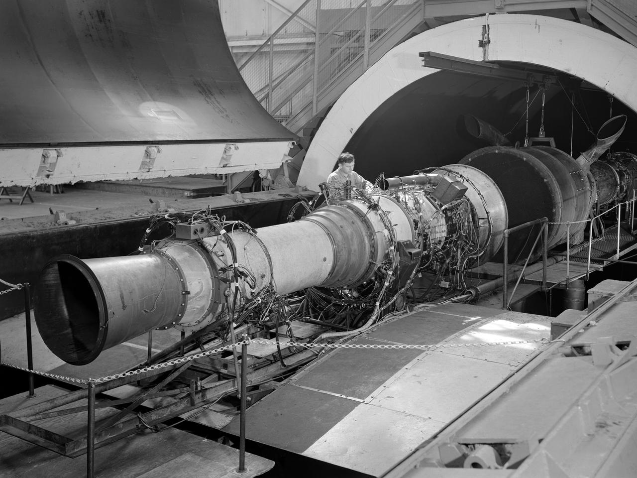
A Rolls Royce Avon RA-14 engine was tested in the Altitude Wind Tunnel at the National Advisory Committee for Aeronautics’ (NACA) Lewis Flight Propulsion Laboratory. The Avon RA-14 engine was a 16-stage axial-flow compressor turbojet capable of producing 9,500 pounds of thrust. The Avon replaced Rolls Royce’s successful Nene engine in 1950 and remained in service until 1974. It was one of several British engines studied in the tunnel during the 1950s. The Altitude Wind Tunnel went through a series of modifications in 1951 to increase its capabilities. An annex was attached to the Exhauster Building to house three new Ingersoll-Rand compressors. The wooden blades on the tunnel’s 31-foot diameter fan were replaced, a pump house and exhaust cooler were constructed underneath the tunnel, and two new cells were added to the cooling tower. The modified wind tunnel continued to analyze jet engines in the 1950s, although the engines, like the RA-14 seen here, were much more powerful than those studied several years before. Lewis researchers studied the RA-14 turbojet engine in the Altitude Wind Tunnel for 11 months in 1956. The engine was mounted on a stand capable of gauging engine thrust, and the tunnel’s air was ducted to the engine through a venturi and bellmouth inlet, seen in this photograph. The initial studies established the engine’s performance characteristics with a fixed-area nozzle and its acceleration characteristics. The researchers also used the tunnel to investigate windmilling of the compressor blades, restarting at high altitudes, and the engine’s performance limits at altitude.
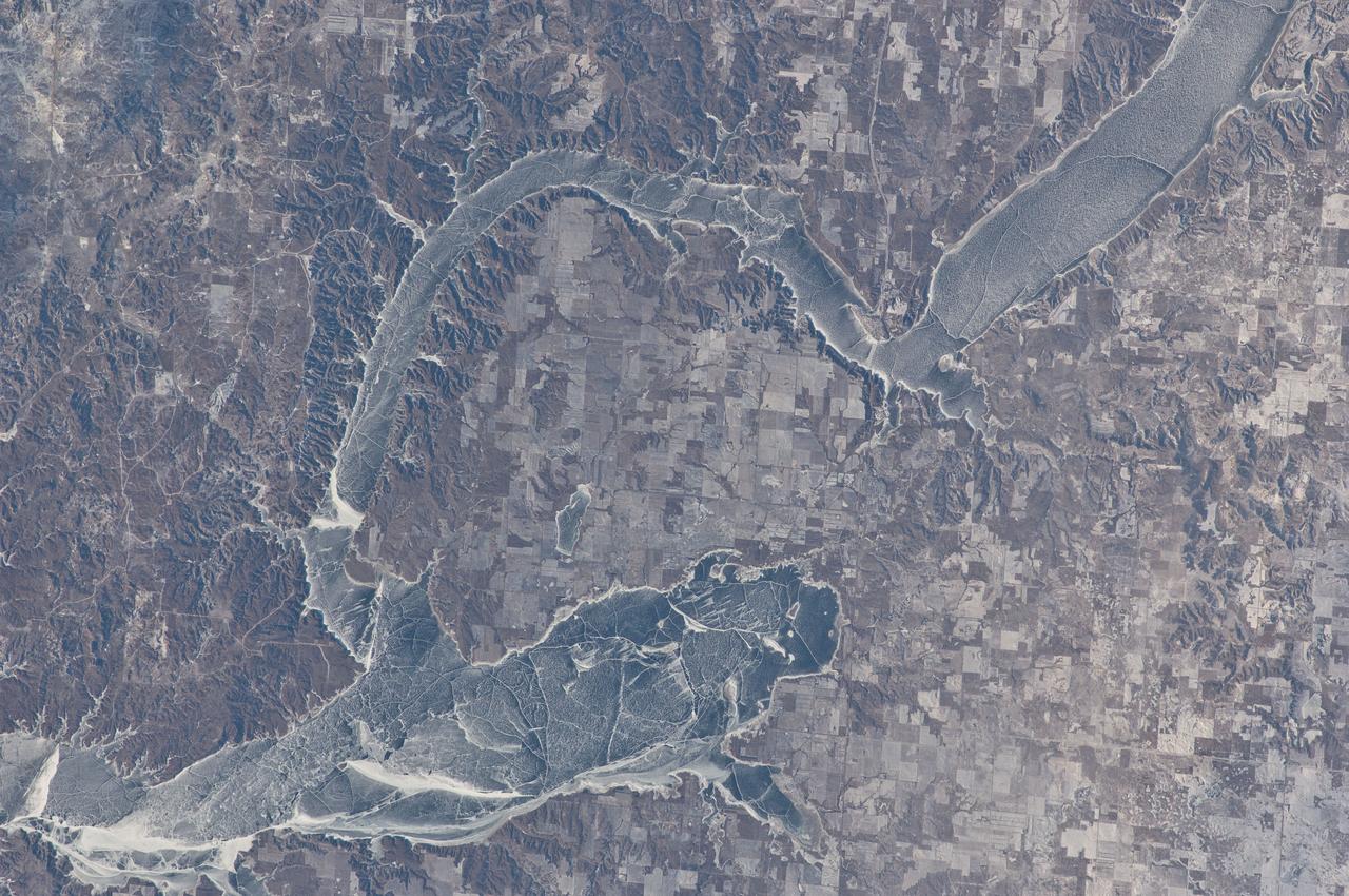
ISS030-E-059433 (19 Jan. 2012) --- Ice cover on Lake Sakakawea in North Dakota is featured in this image photographed by an Expedition 30 crew member on the International Space Station. This striking photograph illustrates the harsh winter conditions frequently experienced in North Dakota. Ice covers the surface of northwestern Lake Sakakawea, a reservoir on the Missouri River in west-central North Dakota. A local weather station near New Town, ND reported an air temperature of approximately -24 °C (-11 °F), with a wind chill of approximately -32 °C (-25 °F) at 10:36 local time – six minutes before the image was taken. In addition to the grey ice on the lake, a dusting of white snow highlights agricultural fields to the north and northeast, as well as fissures and irregularities in the ice surfaces. For a sense of scale, the arms of the lake to either side of New Town are approximately 10 kilometers (6 miles) apart. Lake Sakakawea is named—in the Hidatsa language—for the Shoshone woman generally known as Sacagawea, or “Bird Woman”. She accompanied the Lewis and Clark Expedition in 1805–1806 as an interpreter and guide. The lake was created following the completion of Garrison Dam (not shown) on the Missouri River in 1954. With a surface area of approximately 148,924 hectares (368,000 acres) and length of 286 kilometers (178 miles), Lake Sakakawea is one of the largest artificial reservoirs in the USA.
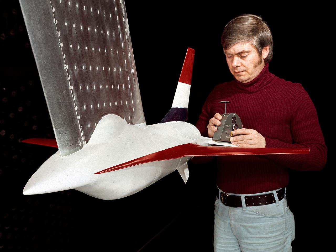
A model of the General Dynamics YF-16 Fighting Falcon in the test section of the 8- by 6-Foot Supersonic Wind Tunnel at the National Aeronautics and Space Administration (NASA) Lewis Research Center. The YF-16 was General Dynamics response to the military’s 1972 request for proposals to design a new 20,000-pound fighter jet with exceptional acceleration, turn rate, and range. The aircraft included innovative design elements to help pilots survive turns up to 9Gs, a new frameless bubble canopy, and a Pratt and Whitney 24,000-pound thrust F-100 engine. The YF-16 made its initial flight in February 1974, just six weeks before this photograph, at Edwards Air Force Base. Less than a year later, the Air Force ordered 650 of the aircraft, designated as F-16 Fighting Falcons. The March and April 1974 tests in the 8- by 6-foot tunnel analyzed the aircraft’s fixed-shroud ejector nozzle. The fixed-nozzle area limited drag, but also limited the nozzle’s internal performance. NASA researchers identified and assessed aerodynamic and aerodynamic-propulsion interaction uncertainties associated the prototype concept. YF-16 models were also tested extensively in the 11- by 11-Foot Transonic Wind Tunnel and 9- by 7-Foot Supersonic Wind Tunnel at Ames Research Center and the 12-Foot Pressure Wind Tunnel at Langley Research Center.
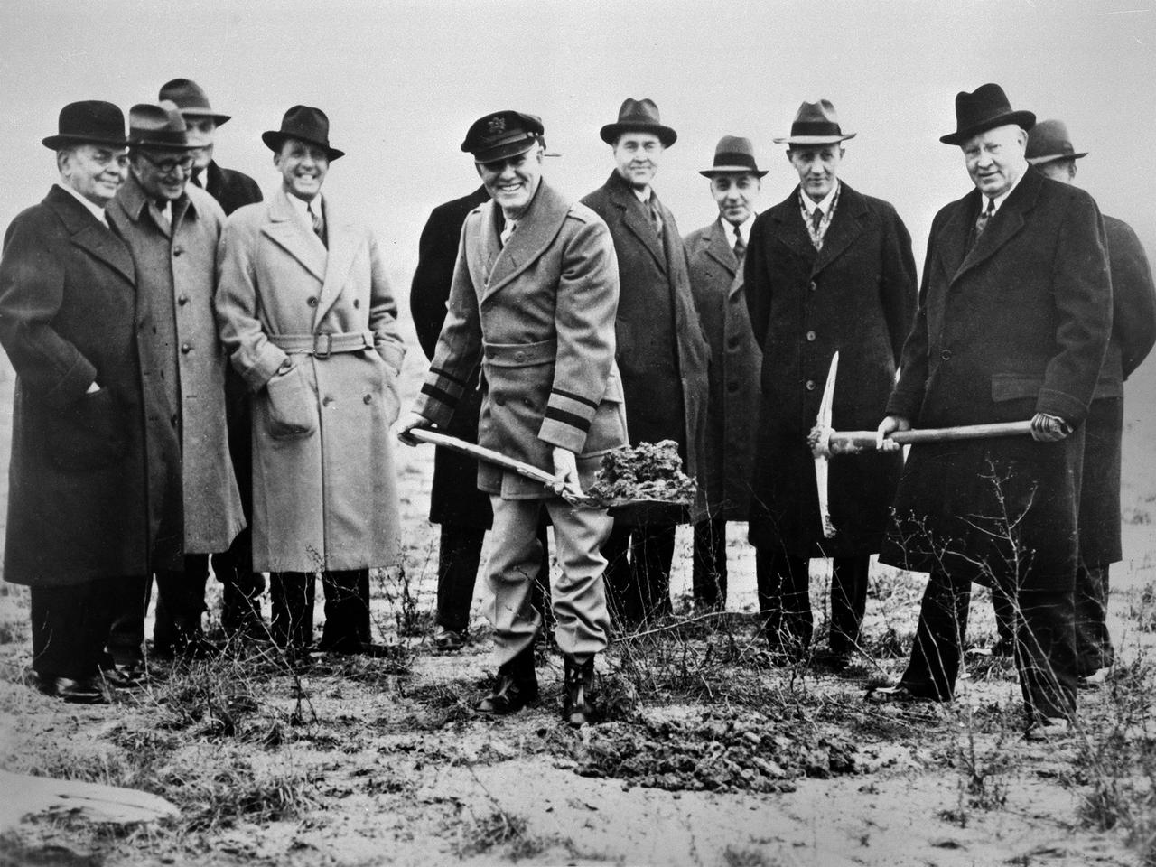
Local politicians and National Advisory Committee for Aeronautics (NACA) officials were on hand for the January 23, 1941 groundbreaking for the NACA’s Aircraft Engine Research Laboratory (AERL). The NACA was established in 1915 to coordinate the nation’s aeronautical research. The committee opened a research laboratory at Langley Field in 1920. By the late 1930s, however, European nations, Germany in particular, were building faster and higher flying aircraft. The NACA decided to expand with a new Ames Aeronautical Laboratory dedicated to high-speed flight and the AERL to handle engine-related research. The NACA examined a number of Midwest locations for its new engine lab before deciding on Cleveland. At the time, Cleveland possessed the nation’s most advanced airport, several key aircraft manufacturing companies, and was home to the National Air Races. Local officials were also able to broker a deal with the power company to discount its electricity rates if the large wind tunnels were operated overnight. The decision was made in October 1940, and the groundbreaking alongside the airport took place on January 23, 1941. From left to right: William Hopkins, John Berry, Ray Sharp, Frederick Crawford, George Brett, Edward Warner, Sydney Kraus, Edward Blythin, and George Lewis
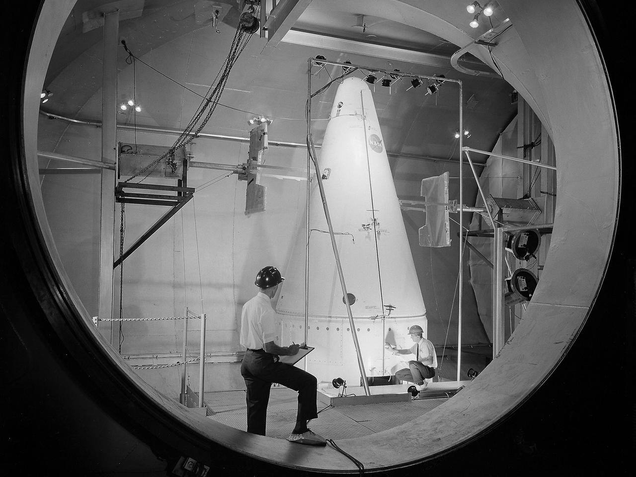
Researchers prepare a Centaur-Surveyor nose cone shroud for a separation test in the Space Power Chambers at the National Aeronautics and Space Administration (NASA) Lewis Research Center. Lewis was in the midst of an extensive effort to prepare the Centaur second-stage rocket for its missions to send the Surveyor spacecraft to the moon as a precursor to the Apollo missions. The nose fairing provided an aerodynamic shield for the payload, guidance system, and electronics package as the rocket traveled through the Earth’s atmosphere. Upon entering space, the thruster near the tip of the fairing forced the two pieces away from the space vehicle. The June 30, 1964 launch of Atlas-Centaur-3 was successful. Within a month of the launch, a Centaur shroud was obtained and installed in the Space Power Chambers. The facility was the only space tank in the country large enough to accommodate the hardware. The two halves of the fiberglass fairing were mounted vertically to a platform. Aluminum pads were set up on either side to catch the shroud halves as they were jettisoned, and a myriad of high-speed cameras were installed to record the tests. The shroud was badly damaged during the first test. It was replaced, and the test equipment redesigned. Over the course of 11 runs during the summer of 1964, the redesigned bulkhead was retested and the new fairing was validated by the final jettison on November 24, 1964. Just over two weeks later, Atlas-Centaur-4 successfully launched a mock-up Surveyor spacecraft into orbit. It was the first Centaur mission to have an error-free shroud jettison.
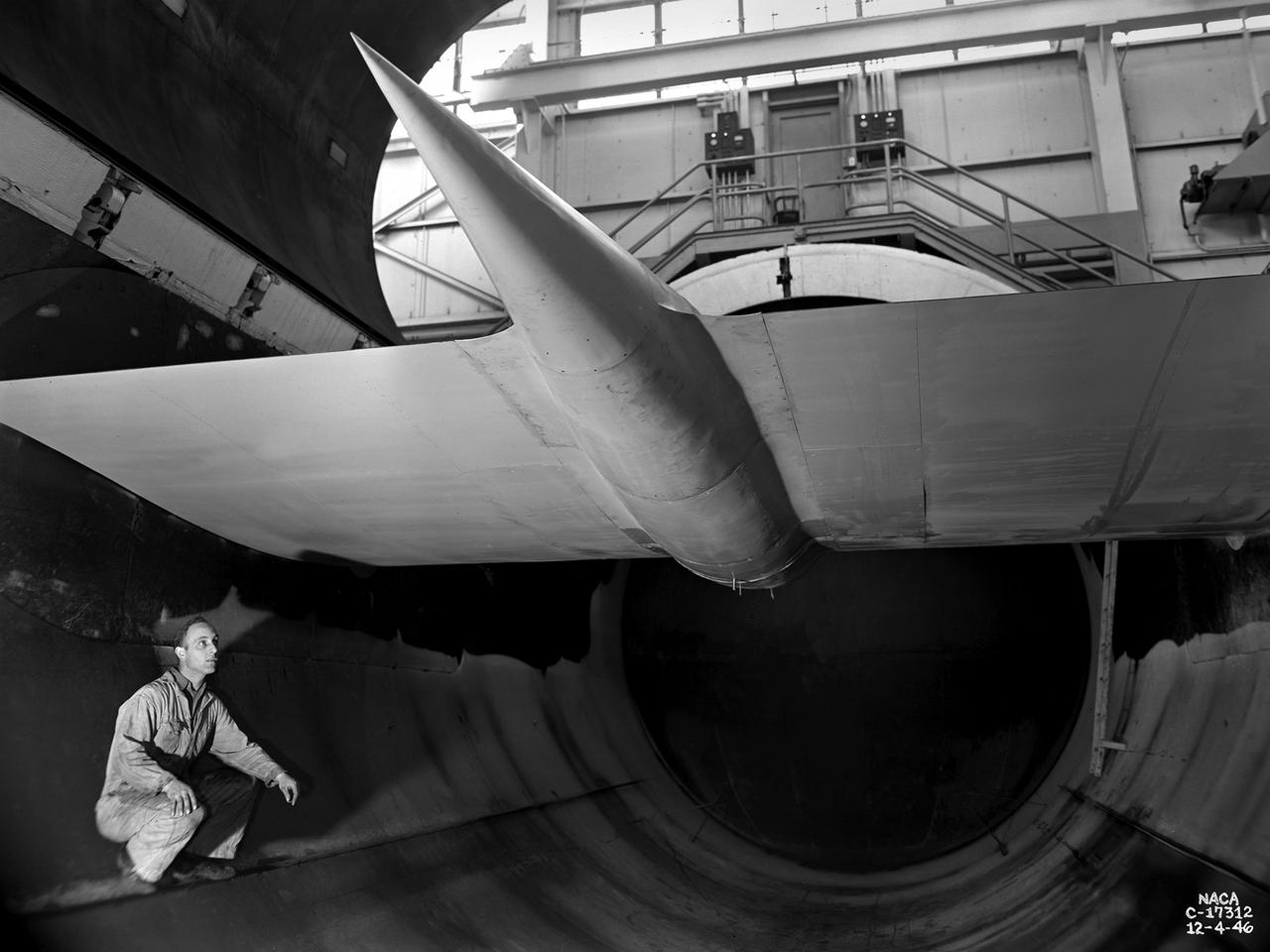
A General Electric TG-100A seen from the rear in the test section of the Altitude Wind Tunnel at the National Advisory Committee for Aeronautics (NACA) Lewis Flight Propulsion Laboratory in Cleveland, Ohio. The Altitude Wind Tunnel was used to study almost every model of US turbojet that emerged in the 1940s, as well as some ramjets and turboprops. In the early 1940s the military was interested in an engine that would use less fuel than the early jets but would keep up with them performance-wise. Turboprops seemed like a plausible solution. They could move a large volume of air and thus required less engine speed and less fuel. Researchers at General Electric’s plant in Schenectady, New York worked on the turboprop for several years in the 1930s. They received an army contract in 1941 to design a turboprop engine using an axial-flow compressor. The result was the 14-stage TG-100, the nation's first turboprop aircraft engine. Development of the engine was slow, however, and the military asked NACA Lewis to analyze the engine’s performance. The TG-100A was tested in the Altitude Wind Tunnel and it was determined that the compressors, combustion chamber, and turbine were impervious to changes in altitude. The researchers also established the optimal engine speed and propeller angle at simulated altitudes up to 35,000 feet. Despite these findings, development of the TG-100 was cancelled in May 1947. Twenty-eight of the engines were produced, but they were never incorporated into production aircraft.
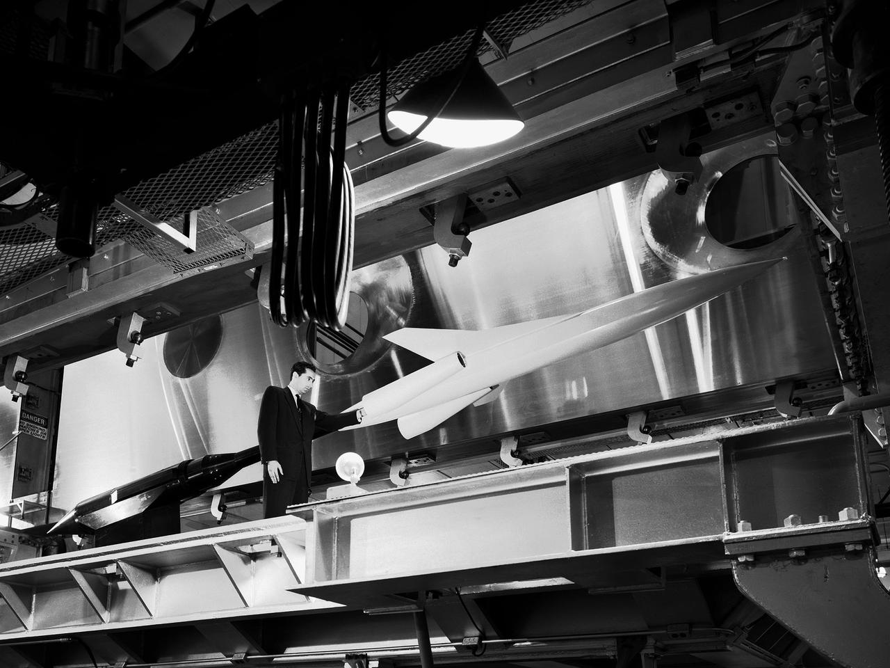
A researcher examines a model being installed in the test section of the 10- by 10-Foot Supersonic Wind Tunnel during the 1957 Inspection of the National Advisory Committee for Aeronautics (NACA) Lewis Flight Propulsion Laboratory. The NACA held its annual Inspection at one of its three research laboratories. Representatives from the military, aeronautical industry, universities, and the press were invited to the laboratory to be briefed on the NACA’s latest research efforts and tour the state- of- the- art test facilities. Over 1700 people visited the NACA Lewis in Cleveland, Ohio during the October 7 - 10, 1957 Inspection. NACA researchers Leonard Obery, seen here, James Connors, Leonard, Stitt, David Bowditch gave presentations on high Mach number turbojets at the 10- by 10 tunnel. It had been only 15 years since a jet aircraft had first flown in the US. Since then the sound barrier had been broken and speeds of Mach 2.5 had been achieved. In the late 1950s NACA researchers sought to create an engine that could achieve Mach 4. This type of engine would require an extremely long inlet and nozzle which would have to be capable of adjusting their diameter for different speeds. A Mach 4 engine would require new composite materials to withstand the severe conditions, modified airframes to hold the longer engines, and high temperature seals and lubricants. The 10- by 10-foot tunnel, which had only been in operation for a year and a half, would play a critical role in these studies. NACA researchers at other facilities discussed high energy aircraft fuels and rocket propellants, aircraft noise reduction, hypersonic flight, nuclear propulsion, and high temperature materials.
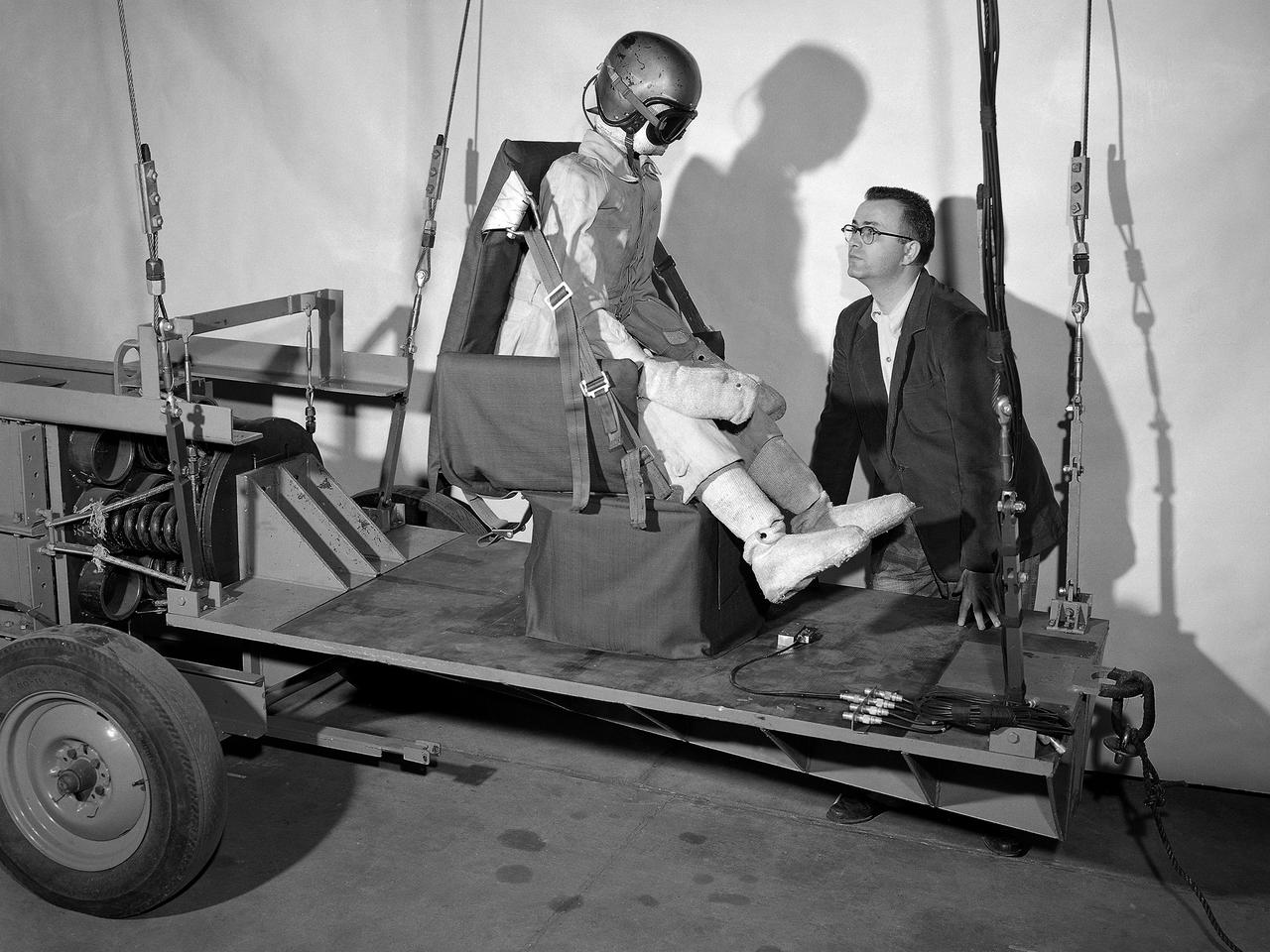
A researcher at the National Advisory Committee for Aeronautics (NACA) Lewis Flight Propulsion Laboratory prepares for a test of an NACA-designed aircraft seat. The laboratory had undertaken a multi-year investigation into the causes and prevention of fires on low altitude aircraft crashes. The program was expanded in the mid-1950s to include the study of impact on passengers, types of seat restraints, and seat design. The crash impact portion of the program began by purposely wrecking surplus Fairchild C-82 Packet and Piper Cub aircraft into barricades at the end of a test runway at the Ravenna Arsenal, located approximately 40 miles south of the Lewis lab in Cleveland. Instrumented dummies and cameras were installed in the pilot and passenger areas. After determining the different loads and their effects on the passengers, the NACA researchers began designing new types of seats and restraints. The result was an elastic seat that flexed upon impact, absorbing 75 percent of the loads before it slowly recoiled. This photograph shows the seats mounted on a pendulum with a large spring behind the platform to provide the jolt that mimicked the forces of a crash. The seat was constructed without any potentially damaging metal parts and included rubber-like material, an inflated back and arms, and a seat cushion. After the pendulum tests, the researchers compared the flexible seats to the rigid seats during a crash of a transport aircraft. They found the passengers in the rigid seats received 66 percent higher g-forces than the NACA-designed seats.
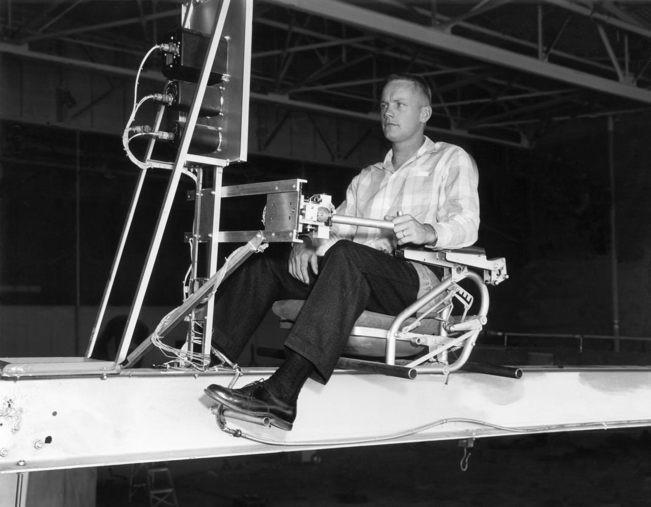
Famed astronaut Neil A. Armstrong, the first man to set foot on the moon during the historic Apollo 11 space mission in July 1969, served for seven years as a research pilot at the NACA-NASA High-Speed Flight Station, now the Dryden Flight Research Center, at Edwards, California, before he entered the space program. Armstrong joined the National Advisory Committee for Aeronautics (NACA) at the Lewis Flight Propulsion Laboratory (later NASA's Lewis Research Center, Cleveland, Ohio, and today the Glenn Research Center) in 1955. Later that year, he transferred to the High-Speed Flight Station at Edwards as an aeronautical research scientist and then as a pilot, a position he held until becoming an astronaut in 1962. He was one of nine NASA astronauts in the second class to be chosen. As a research pilot Armstrong served as project pilot on the F-100A and F-100C aircraft, F-101, and the F-104A. He also flew the X-1B, X-5, F-105, F-106, B-47, KC-135, and Paresev. He left Dryden with a total of over 2450 flying hours. He was a member of the USAF-NASA Dyna-Soar Pilot Consultant Group before the Dyna-Soar project was cancelled, and studied X-20 Dyna-Soar approaches and abort maneuvers through use of the F-102A and F5D jet aircraft. Armstrong was actively engaged in both piloting and engineering aspects of the X-15 program from its inception. He completed the first flight in the aircraft equipped with a new flow-direction sensor (ball nose) and the initial flight in an X-15 equipped with a self-adaptive flight control system. He worked closely with designers and engineers in development of the adaptive system, and made seven flights in the rocket plane from December 1960 until July 1962. During those fights he reached a peak altitude of 207,500 feet in the X-15-3, and a speed of 3,989 mph (Mach 5.74) in the X-15-1. Armstrong has a total of 8 days and 14 hours in space, including 2 hours and 48 minutes walking on the Moon. In March 1966 he was commander of the Gemini 8 or
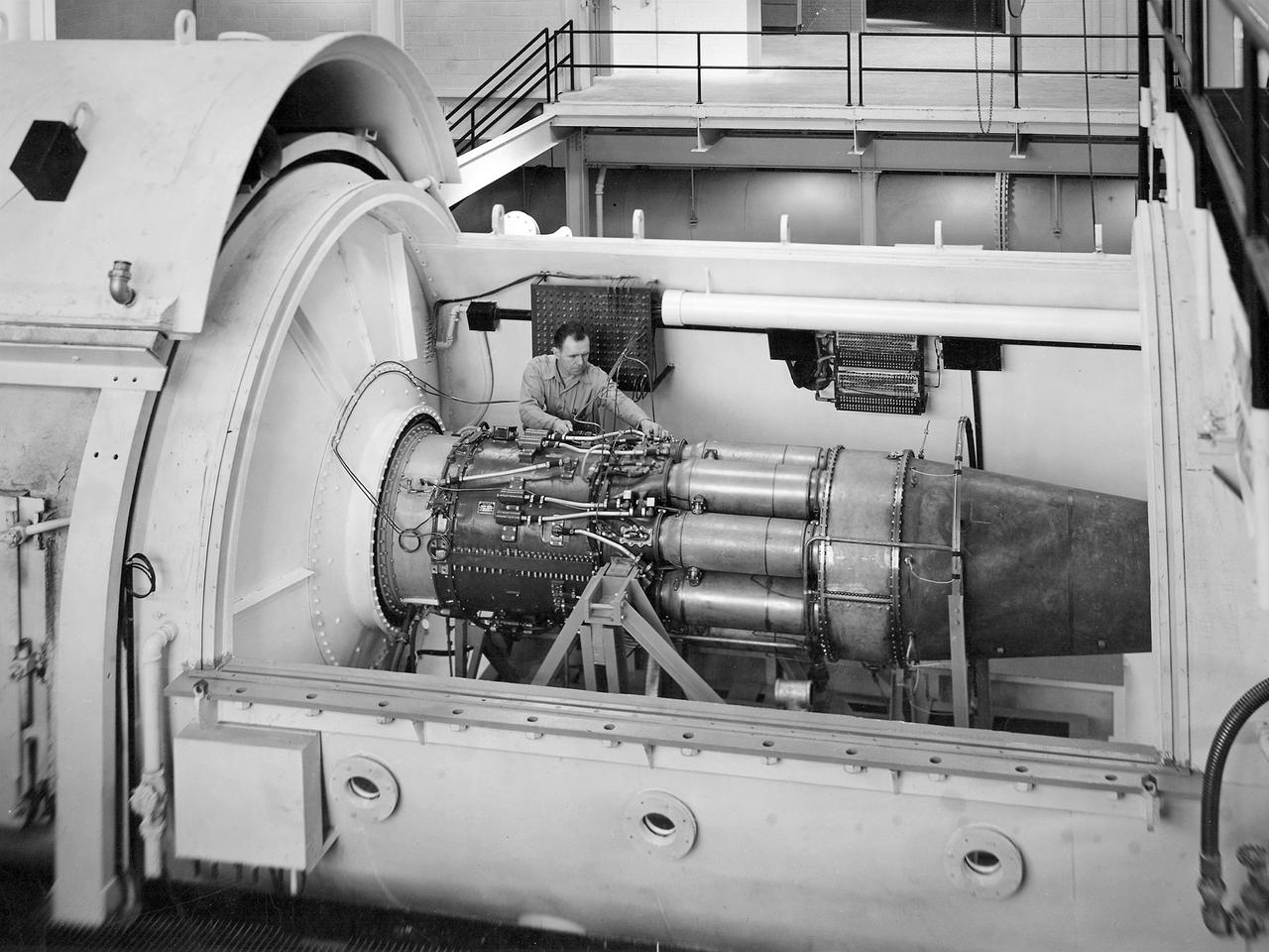
One of the two altitude simulating-test chambers in Engine Research Building at the National Advisory Committee for Aeronautics (NACA) Lewis Flight Propulsion Laboratory. The two chambers were collectively referred to as the Four Burner Area. NACA Lewis’ Altitude Wind Tunnel was the nation’s first major facility used for testing full-scale engines in conditions that realistically simulated actual flight. The wind tunnel was such a success in the mid-1940s that there was a backlog of engines waiting to be tested. The Four Burner chambers were quickly built in 1946 and 1947 to ease the Altitude Wind Tunnel’s congested schedule. The Four Burner Area was located in the southwest wing of the massive Engine Research Building, across the road from the Altitude Wind Tunnel. The two chambers were 10 feet in diameter and 60 feet long. The refrigeration equipment produced the temperatures and the exhauster equipment created the low pressures present at altitudes up to 60,000 feet. In 1947 the Rolls Royce Nene was the first engine tested in the new facility. The mechanic in this photograph is installing a General Electric J-35 engine. Over the next ten years, a variety of studies were conducted using the General Electric J-47 and Wright Aeronautical J-65 turbojets. The two test cells were occasionally used for rocket engines between 1957 and 1959, but other facilities were better suited to the rocket engine testing. The Four Burner Area was shutdown in 1959. After years of inactivity, the facility was removed from the Engine Research Building in late 1973 in order to create the High Temperature and Pressure Combustor Test Facility.
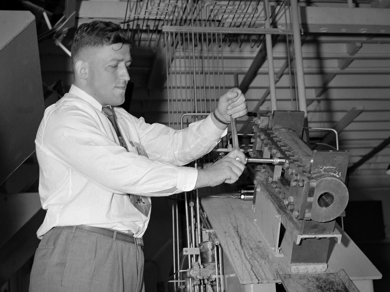
William Kerslake, a combustion researcher at the National Advisory Committee for Aeronautics (NACA) Lewis Flight Propulsion Laboratory, examines the setup of a transparent rocket in a Rocket Laboratory test cell. Kerslake joined NACA Lewis the previous summer after graduating from the Case Institute of Technology with a chemistry degree. His earliest professional research concentrated on combustion instability in small rocket engines. While at Case the quiet, 250-pound Kerslake also demonstrated his athletic prowess on the wrestling team. He continued wrestling for roughly a decade afterwards while conducting his research with the NACA. Kerslake participated in Olympic competitions in Helsinki (1952), Melbourne (1956), and Rome (1960). He won 30 national championships in three different weight classes and captured the gold at the 1955 Pan American Games in Mexico City. Kerslake accomplished all this while maintaining his research career, raising a family, and paying his own expenses. As his wrestling career was winding down in the early 1960s, Kerslake’s professional career changed, as well. He was transferred to Harold Kaufman’s Electrostatic Propulsion Systems Section in the new Electromagnetic Propulsion Division. Kaufman was developing the first successful ion engine at the time, and Kerslake spent the remainder of his career working in the electric propulsion field. He was heavily involved in the two Space Electric Rocket Test (SERT) missions which demonstrated that the ion thrusters could successfully operate in space. Kerslake retired in 1985 with over 30 years of service.
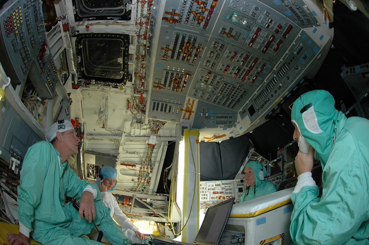
KENNEDY SPACE CENTER, FLA. - In Orbiter Processing Facility bay 2, United Space Alliance employees Charles Bell, Terri Halverstadt, Loralee Woodbury, and Rob Lewis monitor a display in Space Shuttle Endeavour's cockpit the first time the orbiter is powered up after nearly two years. Endeavour has been in its Orbiter Major Modification (OMM) period since December 2003. Engineers and technicians spent 900,000 hours performing 124 modifications to the vehicle. These included all recommended return to flight safety modifications, bonding more than 1,000 thermal protection system tiles and inspecting more than 150 miles of wiring throughout Endeavour. Eighty five of the modifications are completed, with work on the additional 39 modifications continuing throughout the next few months. Shuttle major modification periods are scheduled at regular intervals to enhance safety and performance, infuse new technology and allow for thorough inspections of the airframe and wiring of the vehicles. This was the second of these modification periods performed entirely at Kennedy Space Center. Endeavour's previous modification was completed in March 1997.
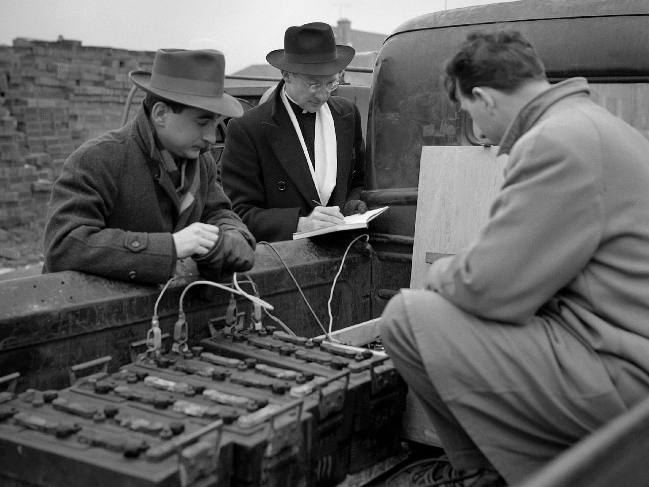
Reverend Henry Birkenhauer and E.F. Carome measure ground vibrations on West 220th Street caused by the operation of the 8- by 6-Foot Supersonic Wind Tunnel at the National Advisory Committee for Aeronautics (NACA) Lewis Flight Propulsion Laboratory. The 8- by 6 was the laboratory’s first large supersonic wind tunnel. It was also the NACA’s most powerful supersonic tunnel, and the NACA’s first facility capable of running an engine at supersonic speeds. The 8- by 6 was originally an open-throat and non-return tunnel. This meant that the supersonic air flow was blown through the test section and out the other end into the atmosphere. Complaints from the local community led to the installation of a muffler at the tunnel exit and the eventual addition of a return leg. Reverend Brikenhauer, a seismologist, and Carome, an electrical technician were brought in from John Carroll University to take vibration measurements during the 8- by 6 tunnel’s first run with a supersonic engine. They found that the majority of the vibrations came from the air and not the ground. The tunnel’s original muffler offered some relief during the facility checkout runs, but it proved inadequate during the operation of an engine in the test section. Tunnel operation was suspended until a new muffler was designed and installed. The NACA researchers, however, were pleased with the tunnel’s operation. They claimed it was the first time a jet engine was operated in an airflow faster than Mach 2.
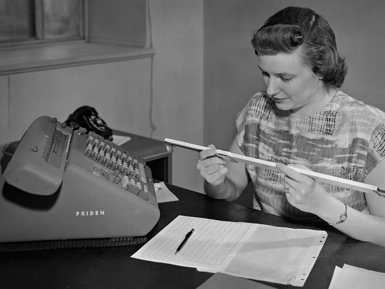
A female computer at the National Advisory Committee for Aeronautics (NACA) Lewis Flight Propulsion Laboratory with a slide rule and Friden adding machine to make computations. The computer staff was introduced during World War II to relieve short-handed research engineers of some of the tedious computational work. The Computing Section was staffed by “computers,” young female employees, who often worked overnight when most of the tests were run. The computers obtained test data from the manometers and other instruments, made the initial computations, and plotted the data graphically. Researchers then analyzed the data and summarized the findings in a report or made modifications and ran the test again. There were over 400 female employees at the laboratory in 1944, including 100 computers. The use of computers was originally planned only for the duration of the war. The system was so successful that it was extended into the 1960s. The computers and analysts were located in the Altitude Wind Tunnel Shop and Office Building office wing during the 1940s and transferred to the new 8- by 6-Foot Supersonic Wind Tunnel in 1948.
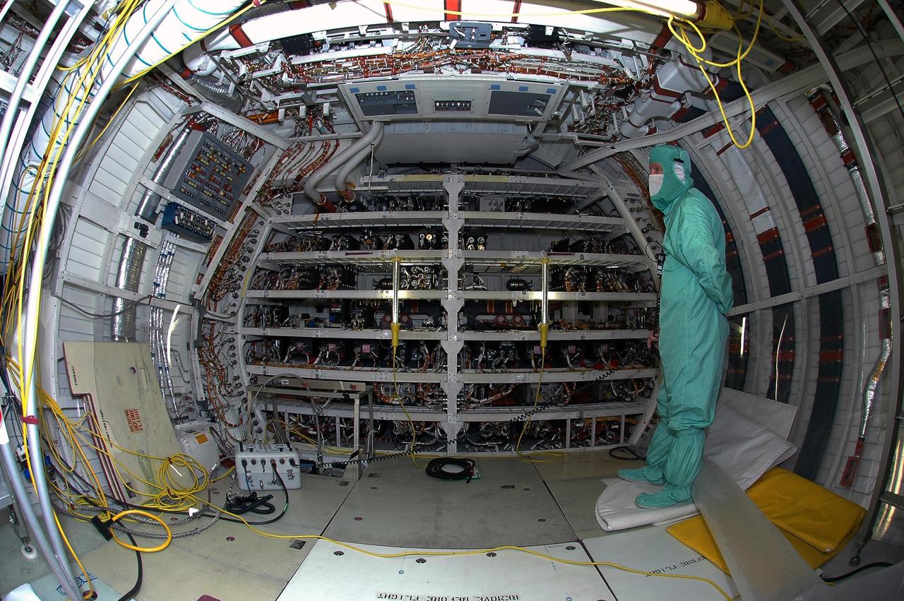
KENNEDY SPACE CENTER, FLA. - In Orbiter Processing Facility bay 2, United Space Alliance technician Rob Lewis monitors Space Shuttle Endeavour's electrical system the first time the orbiter is powered up after nearly two years. Endeavour has been in its Orbiter Major Modification (OMM) period since December 2003. Engineers and technicians spent 900,000 hours performing 124 modifications to the vehicle. These included all recommended return to flight safety modifications, bonding more than 1,000 thermal protection system tiles and inspecting more than 150 miles of wiring throughout Endeavour. Eighty five of the modifications are completed, with work on the additional 39 modifications continuing throughout the next few months. Shuttle major modification periods are scheduled at regular intervals to enhance safety and performance, infuse new technology and allow for thorough inspections of the airframe and wiring of the vehicles. This was the second of these modification periods performed entirely at Kennedy Space Center. Endeavour's previous modification was completed in March 1997.

A Wright Aeronautical XRJ47-W-5 ramjet installed in a test chamber of the National Advisory Committee for Aeronautics’ (NACA) new Propulsion Systems Laboratory at the Lewis Flight Propulsion Laboratory. Construction of the facility had only recently been completed, and NACA engineers were still testing the various operating systems. The Propulsion Systems Laboratory was the NACA’s most powerful facility for testing full-scale engines in simulated flight altitudes. It contained two 14-foot diameter and 100-foot-long altitude chambers that ran parallel to one another with a control room in between. The engine being tested was installed inside the test section of one of the chambers, seen in this photograph. Extensive instrumentation was fitted onto the engine prior to the test. Once the chamber was sealed, the altitude conditions were introduced, and the engine was ignited. Operators in the control room could run the engine at the various speeds and adjust the altitude conditions to the desired levels. The engine’s exhaust was ejected into the cooling equipment. Two 48-inch diameter XRJ47-W-5 ramjets were used to power the North American Aviation Navaho Missile. The Navaho was a winged missile that was intended to travel up to 3000 miles carrying a nuclear warhead. It was launched using rocket booster engines that were ejected after the missile’s ramjet engines were ignited.
Marie Lewis, NASA Communications, moderates a prelaunch news conference for NASA’s Landsat 9 mission at Vandenberg Space Force Base in California on Saturday, Sept. 25, 2021. Participants include Thomas Zurbuchen, associate administrator, NASA’s Science Mission Directorate; Karen St. Germain, director, NASA’s Earth Science Division; Tanya Trujillo, assistant secretary for water and science, U.S. Department of the Interior; Michael Egan, Landsat program executive, NASA’s Earth Science Division; Tim Dunn, launch director, NASA’s Launch Services Program; Scott Messer, United Launch Alliance program manager, NASA Launch Services Program; and Capt. Addison Nichols, weather officer, Space Launch Delta 30. Landsat 9 is scheduled to launch at 2:12 p.m. EDT (11:12 a.m. PDT) on Monday, Sept. 27, on a United Launch Alliance Atlas V 401 rocket from Space Launch Complex 3 at Vandenberg. The launch is managed by NASA’s Launch Services Program, based at the agency’s Kennedy Space Center in Florida. Landsat 9 will join its sister satellite, Landsat 8, in orbit in collecting images from across the planet every eight days. This calibrated data will continue the Landsat program’s critical role in monitoring the health of Earth and helping people manage essential resources, including crops, irrigation water, and forests.
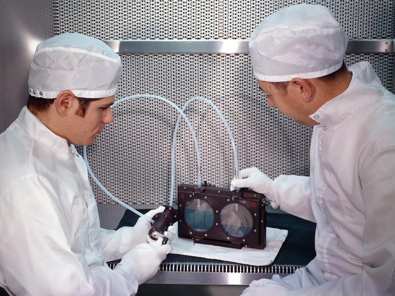
Two researchers at the National Aeronautics and Space Administration (NASA) Lewis Research Center demonstrate the test equipment they devised to study the transfer of liquid in microgravity onboard the Apollo 14 mission. The test was an early step in developing the ability to transfer liquids from a tanker vehicle to spacecraft in space. Researchers needed to know the tank’s outflow characteristics, the fluid’s behavior when entering new tank, and the effects of accelerations. Others had performed some calculations and analytical studies, but no one had examined the complete transfer from one tank to another in microgravity. The early calculations concluded that the transfer process was impossible without devices to control the liquid and gas. This investigation specifically sought to demonstrate the effectiveness of two different surface-tension baffle designs. The experiment was an entirely closed system with two baffled-tanks. The researchers also built a similar device without the baffles. The experiment was carried onboard the Apollo 14 spacecraft and conducted during the coast period on the way to the moon. The two surface tension baffle designs in the separate tanks were shown to be effective both as supply tanks and as receiver tanks. The liquid transferred within two percent of the design value with ingesting gas. The unbaffled tanks ingested gas after only 12-percent of the fluid had transferred.
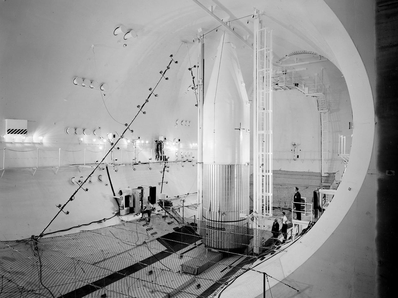
Preparations for a shroud jettison test for the Orbiting Astronomical Observatory-1 (OAO-1) satellite in the Space Power Chambers facility at the National Aeronautics and Space Administration (NASA) Lewis Research Center. The satellite was to be launched on an Atlas-Agena rocket in the spring of 1966. The 3900-pound payload was the heaviest ever attempted by Agena. The satellite was the first of three equipped with powerful telescopes to study ultraviolet data from specific stars and galaxies. In-depth observations were not possible from Earth-bound telescopes because of the filtering and distortion of the atmosphere. The OAO-1 satellite was wider in diameter than the Agena stage, so a new clamshell shroud was created to enclose both the satellite and the Agena. The clamshell shroud consisted of three sections that enclosed both the Agena and OAO-1: a fiberglass nose fairing and aluminum mid and aft fairings. The upper two fairings separated when the Atlas engines stopped, and the aft fairing fell away with the Atlas upon separation from the upper stages The large altitude tank in the Space Power Chambers could simulate altitudes up to 100,000 feet. Three shroud jettison tests were run in July 1965 and the first week of August at a simulated altitude of 20 miles. The April 8, 1966 launch from Cape Canaveral went smoothly, but the OAO-1 satellite failed after only 90 minutes due to a battery failure.
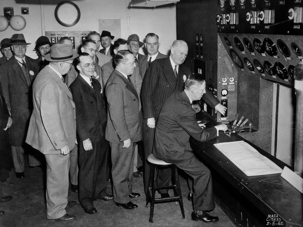
A group of National Advisory Committee for Aeronautics (NACA) officials and local dignitaries were on hand on May 8, 1942, to witness the Initiation of Research at the NACA's new Aircraft Engine Research Laboratory in Cleveland, Ohio. The group in this photograph was in the control room of the laboratory's first test facility, the Engine Propeller Research Building. The NACA press release that day noted, "First actual research activities in what is to be the largest aircraft engine research laboratory in the world was begun today at the National Advisory Committee for Aeronautics laboratory at the Cleveland Municipal Airport.” The ceremony, however, was largely symbolic since most of the laboratory was still under construction. Dr. George W. Lewis, the NACA's Director of Aeronautical Research, and John F. Victory, NACA Secretary, are at the controls in this photograph. Airport Manager John Berry, former City Manager William Hopkins, NACA Assistant Secretary Ed Chamberlain, Langley Engineer-in-Charge Henry Reid, Executive Engineer Carlton Kemper, and Construction Manager Raymond Sharp are also present. The propeller building contained two torque stands to test complete engines at ambient conditions. The facility was primarily used at the time to study engine lubrication and cooling systems for World War II aircraft, which were required to perform at higher altitudes and longer ranges than previous generations.
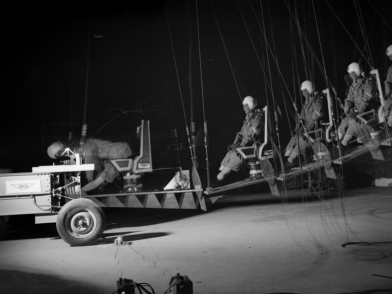
This time-lapse photograph shows the test of a pilot seat and restraint designed by researchers at the National Advisory Committee for Aeronautics (NACA) Lewis Flight Propulsion Laboratory. The laboratory had undertaken a multi-year investigation into the causes and preventative measures for fires resulting from low altitude aircraft crashes. The program was expanded in the mid-1950s to include the study of crash impact on passengers, new types of types of seat restraints, and better seat designs. The impact program began by purposely wrecking surplus transport Fairchild C-82 Packet and Piper Cub aircraft into barricades at the end of a test runway. Instrumented dummies and cameras were installed in the pilot and passenger areas. After determining the different loads experienced during a crash and the effects on the passengers, the NACA researchers began designing new types of seats and restraints. The result was an elastic seat that flexed upon impact, absorbing 75 percent of the loads before it slowly recoiled. This photograph shows the seats mounted on a pendulum with a large spring behind the platform to provide the jolt that mimicked the forces of a crash. The seat was constructed without any potentially damaging metal parts and included rubber-like material, an inflated back and arms, and a seat cushion. After the pendulum tests, the researchers compared the flexible seats to the rigid seats during a crash of a transport aircraft. They found the passengers in the rigid seats received 66 percent higher g-forces than the NACA-designed seats.