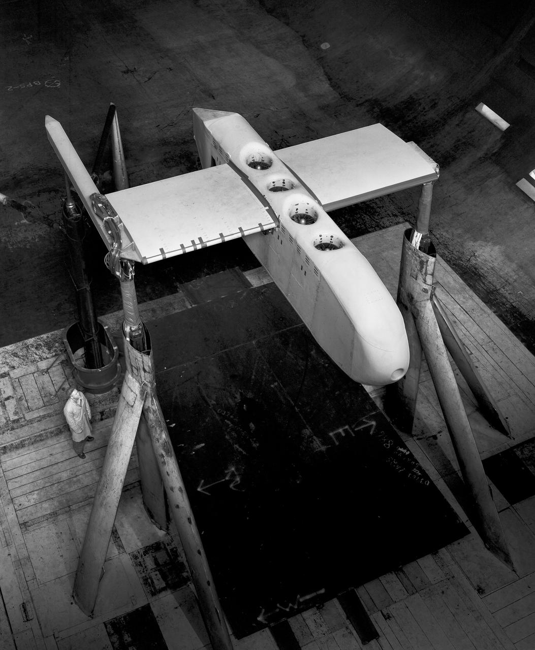
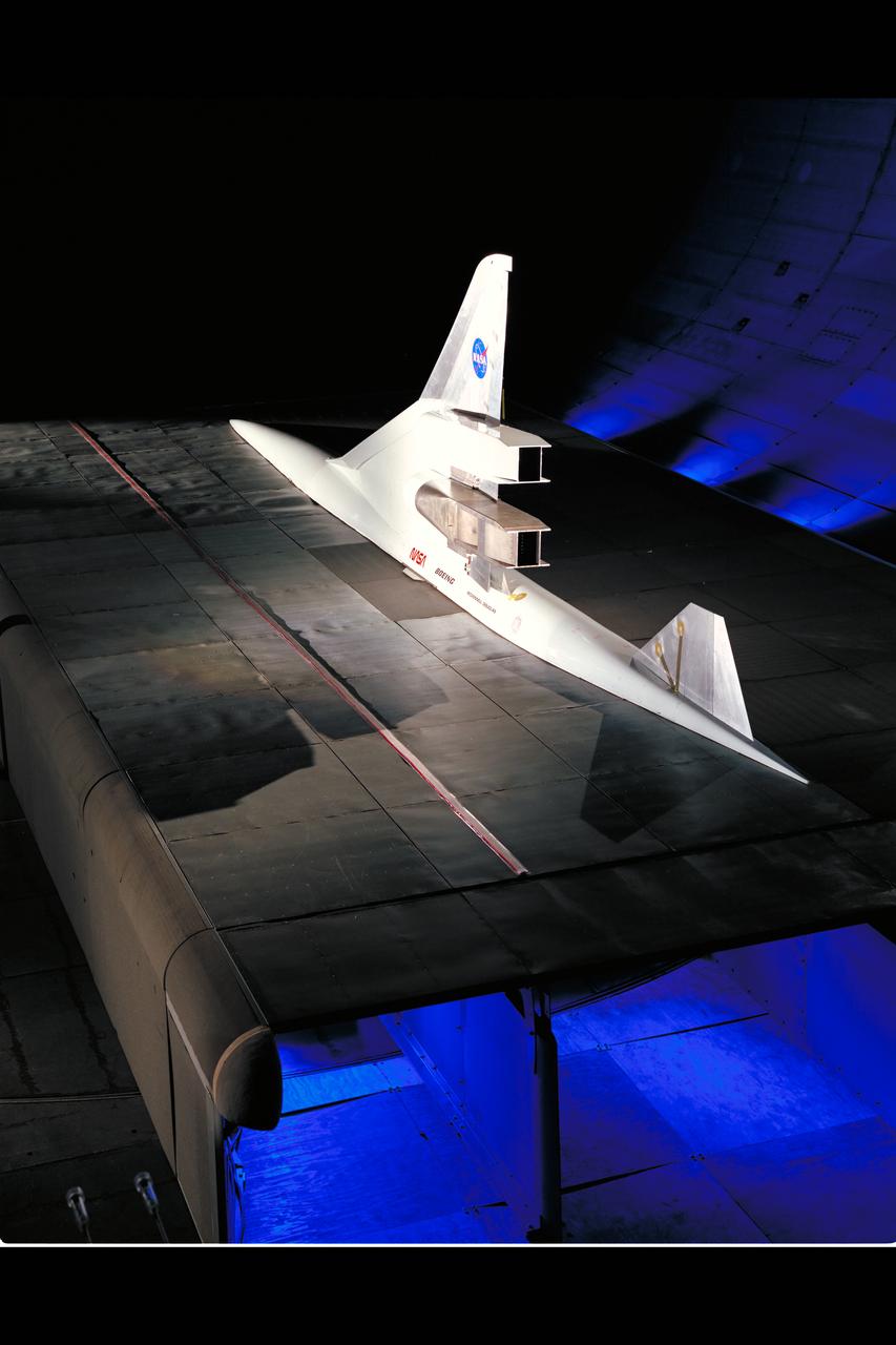
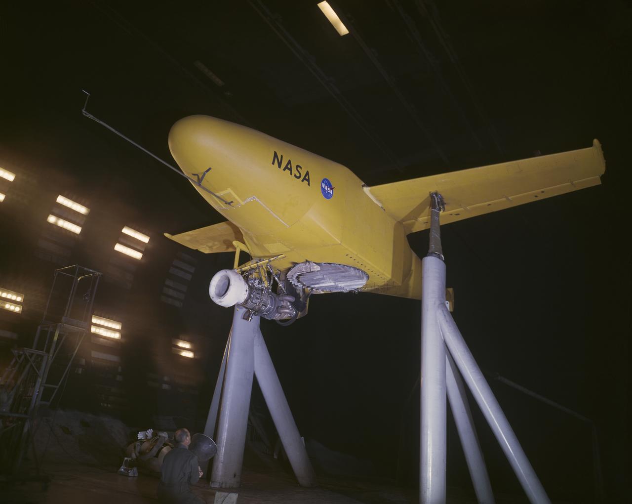
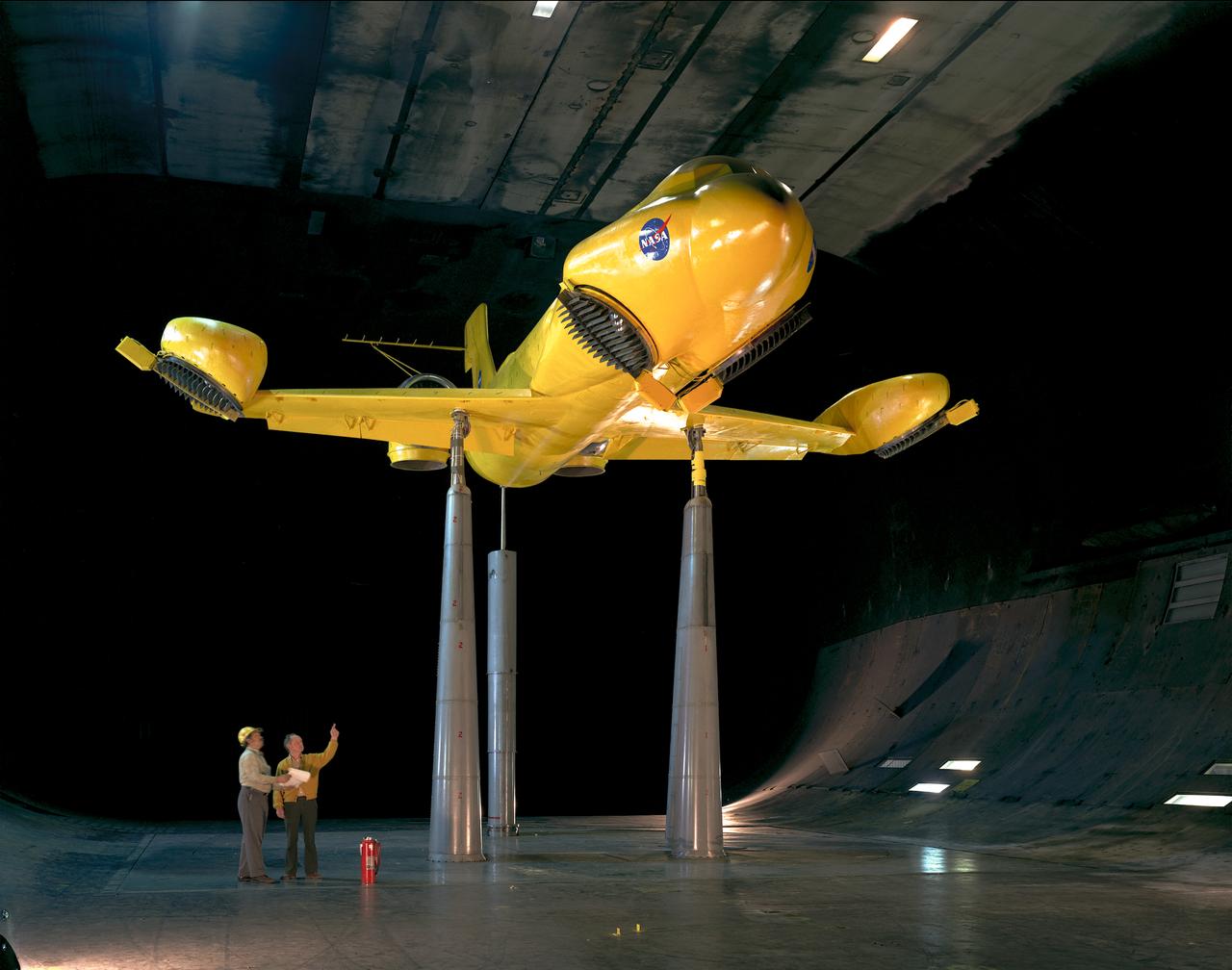
3/4 front, top view of Noriar Lift Engine Pod installation in Ames 40x80 foot wind tunnel
A-38524. Lift engine VSTOL fighter model, 3/4 top front view with jet engines. Edward Varerre, in picture.

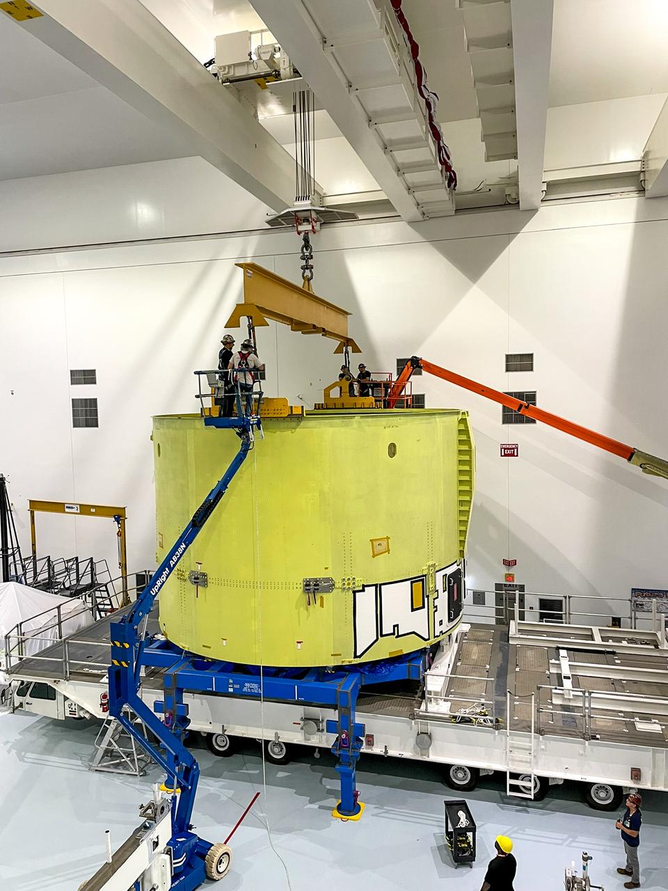
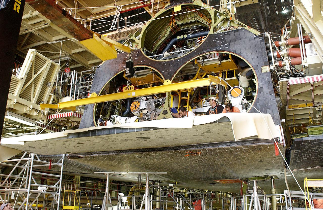
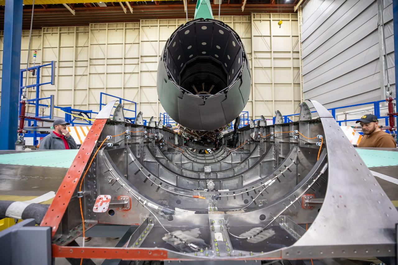
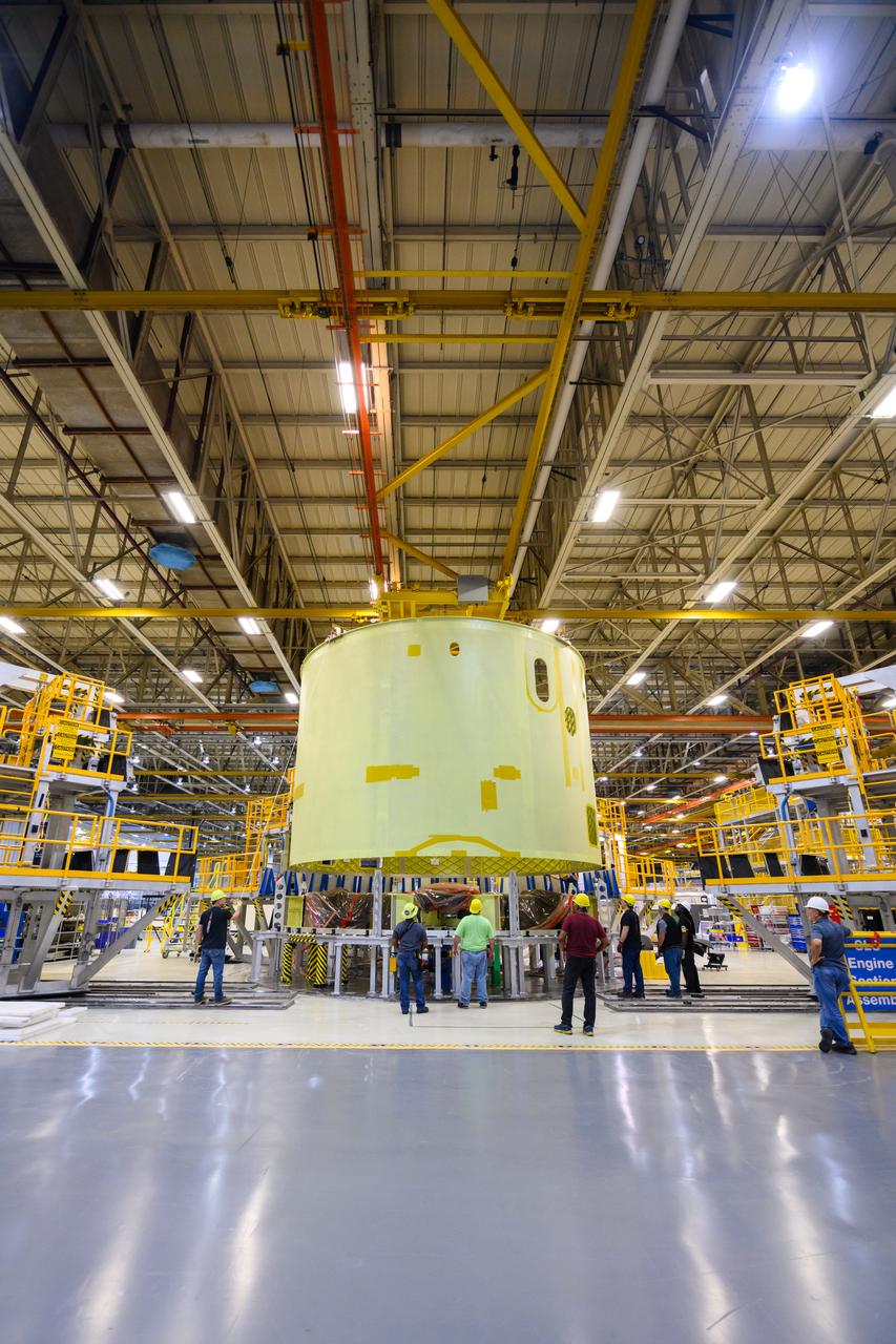
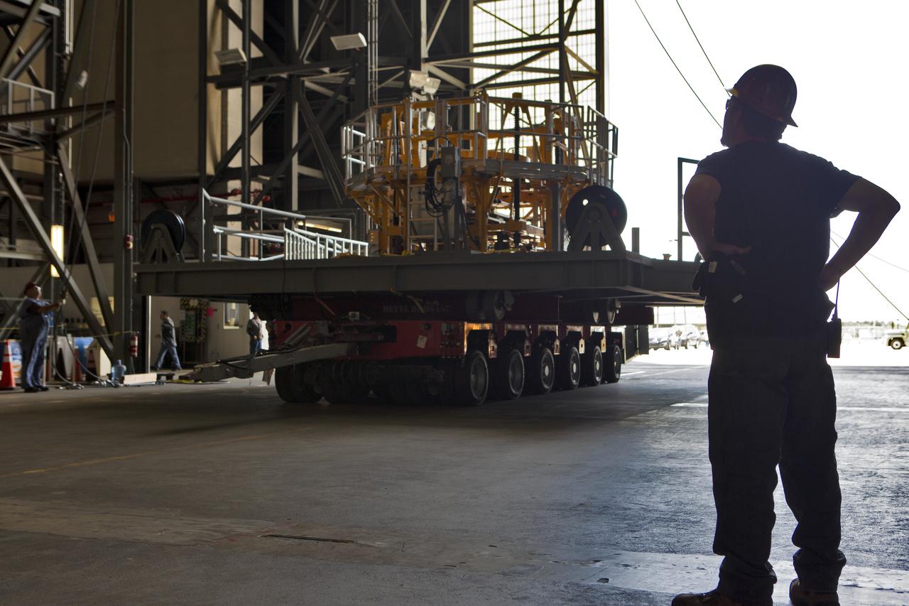
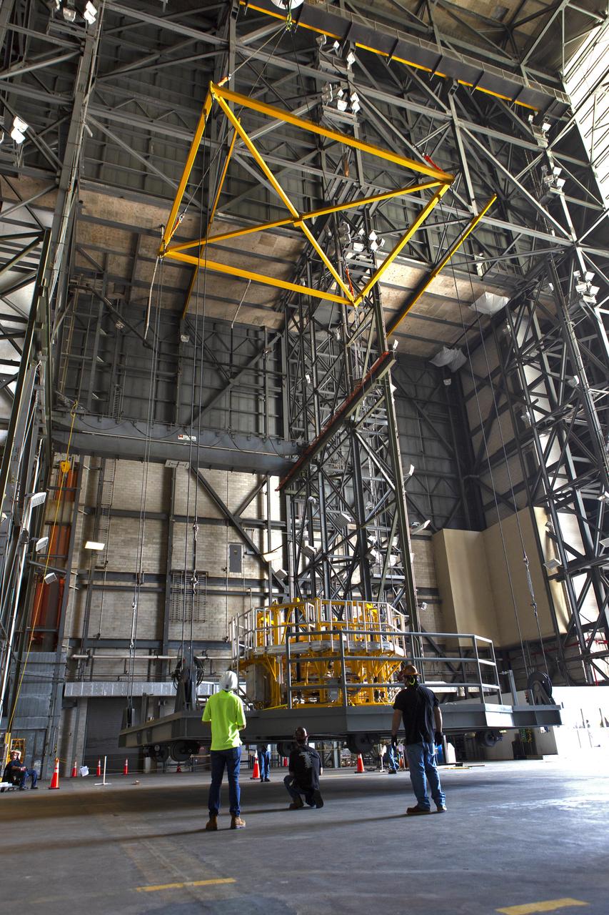
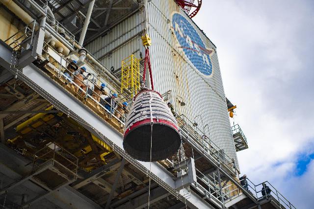
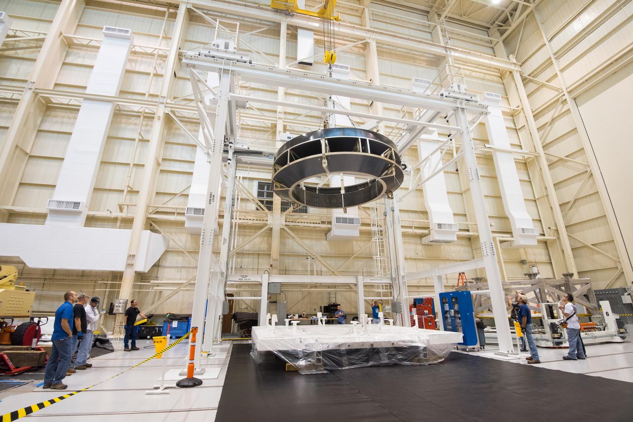
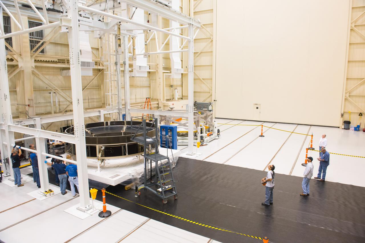
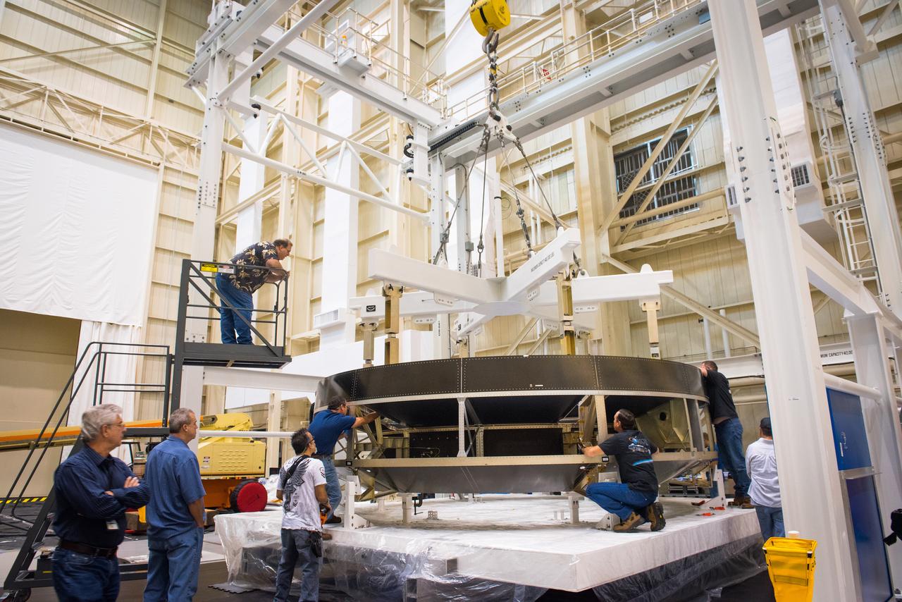
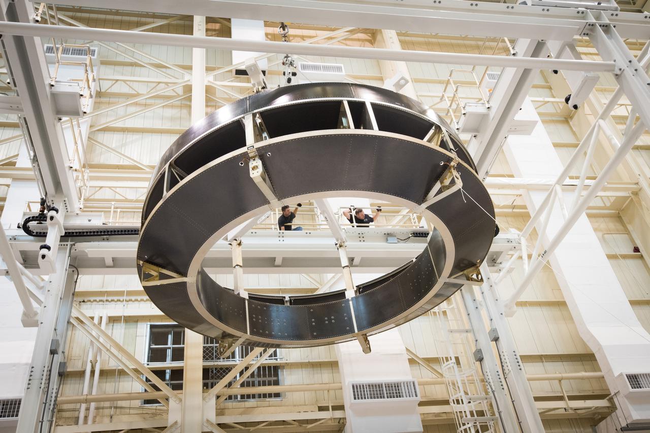
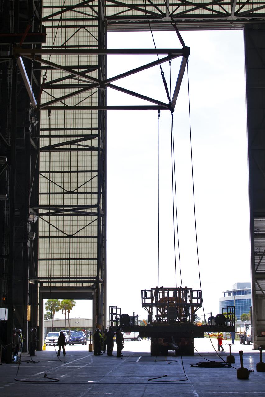
Technicians lift the engine section for NASA’s Artemis IV SLS (Space Launch System) rocket ahead of further processing inside the high bay of the Space Systems Processing Facility at the agency's Kennedy Space Center in Florida on Monday, Oct. 21, 2024. The engine section is one of five major elements that makes up the SLS rocket’s 212-foot-tall core stage, which house the rocket’s four RS-25 engines and vital systems for mounting, controlling, and delivering fuel from the stage’s two massive liquid propellant tanks to the engines.
Technicians lift the engine section for NASA’s Artemis IV SLS (Space Launch System) rocket ahead of further processing inside the high bay of the Space Systems Processing Facility at the agency's Kennedy Space Center in Florida on Monday, Oct. 21, 2024. The engine section is one of five major elements that makes up the SLS rocket’s 212-foot-tall core stage, which house the rocket’s four RS-25 engines and vital systems for mounting, controlling, and delivering fuel from the stage’s two massive liquid propellant tanks to the engines.
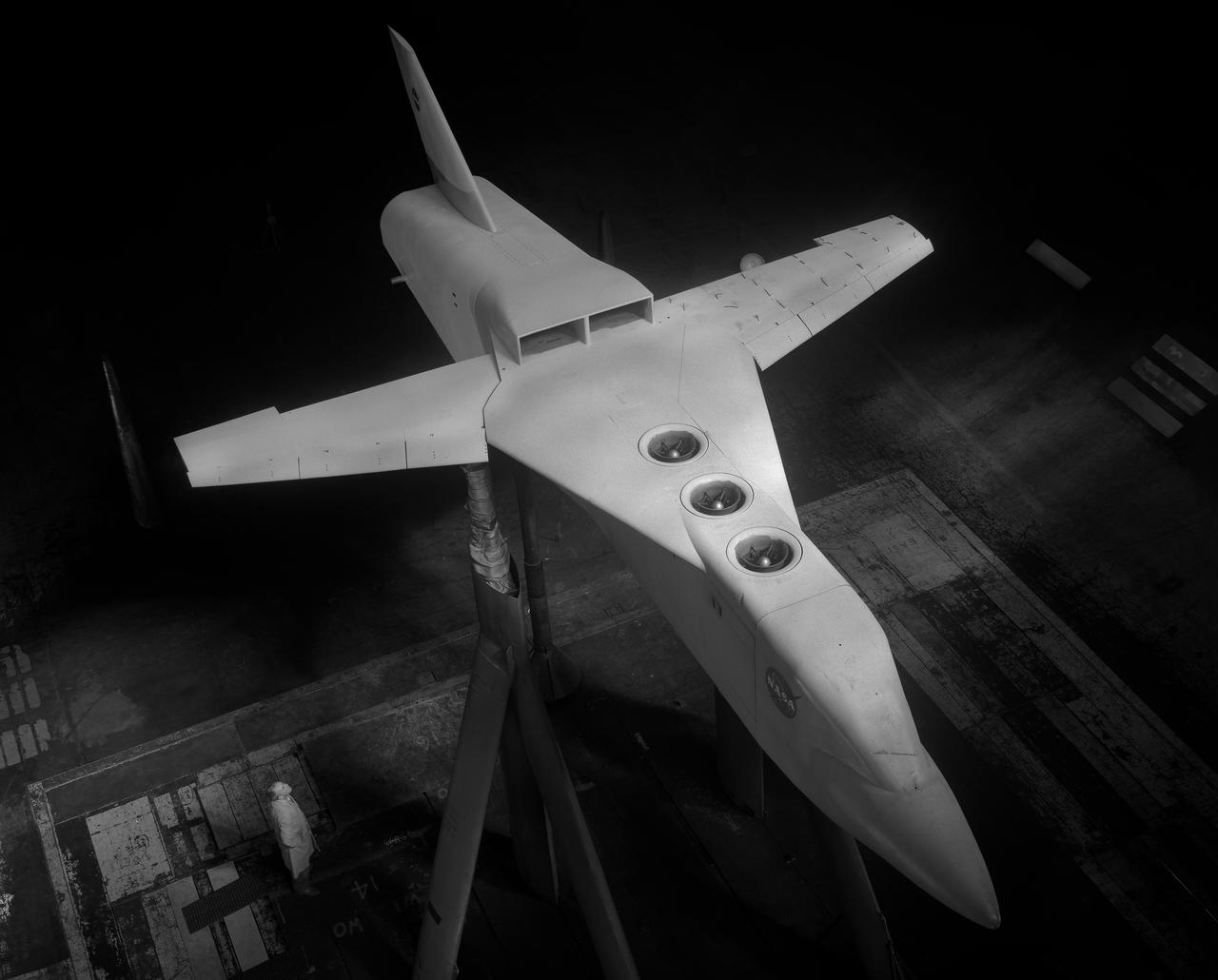
Lift engine VSTOL fighter model, 3/4 lower front view showing jet engines exit vanes. Yarn tufts attached to horizontal tail.
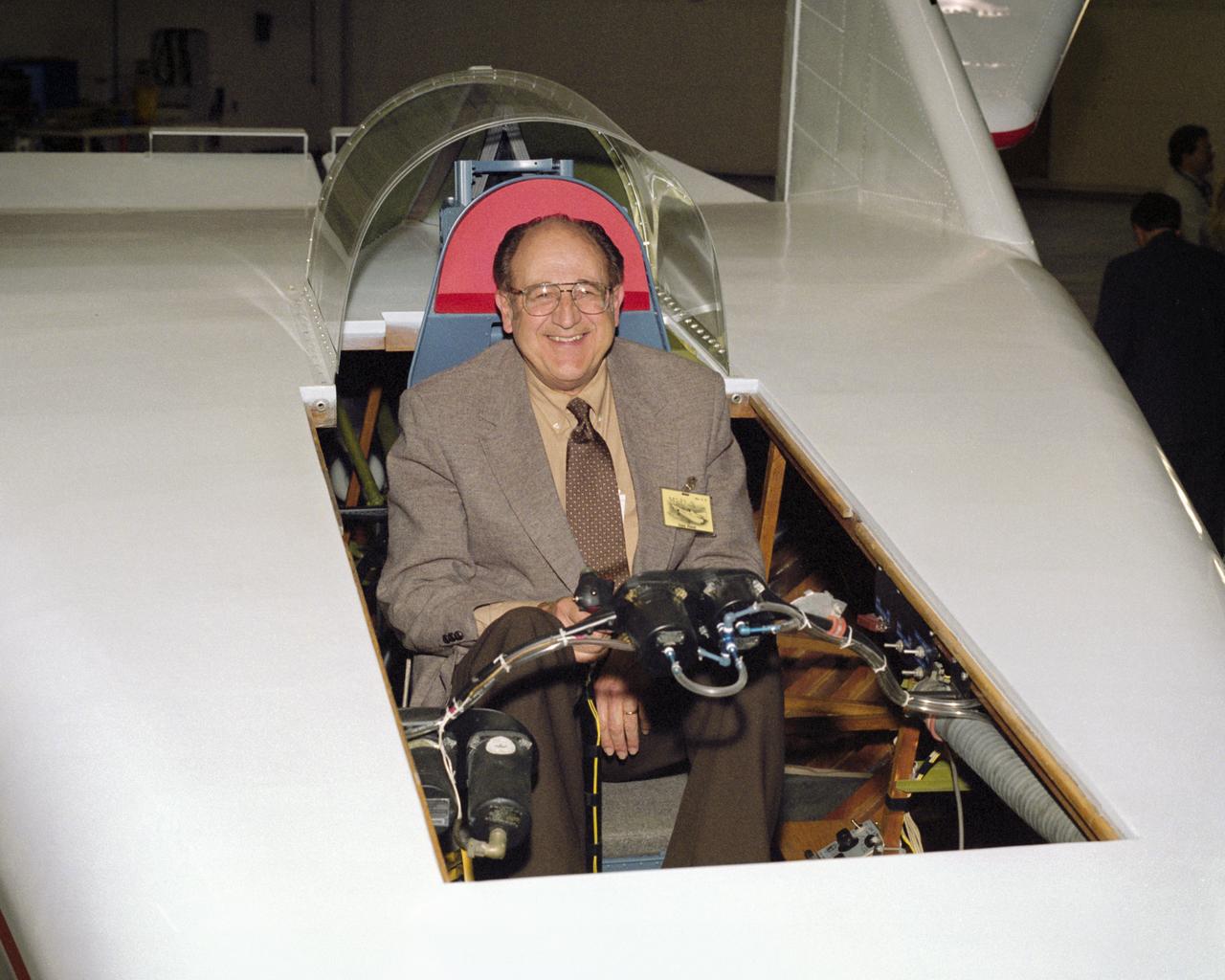
Often called the "Father of the Lifting Bodies," NASA aerospace engineer Dale Reed enjoys a moment in the cockpit of the restored wingless M2-F1 in 1997.
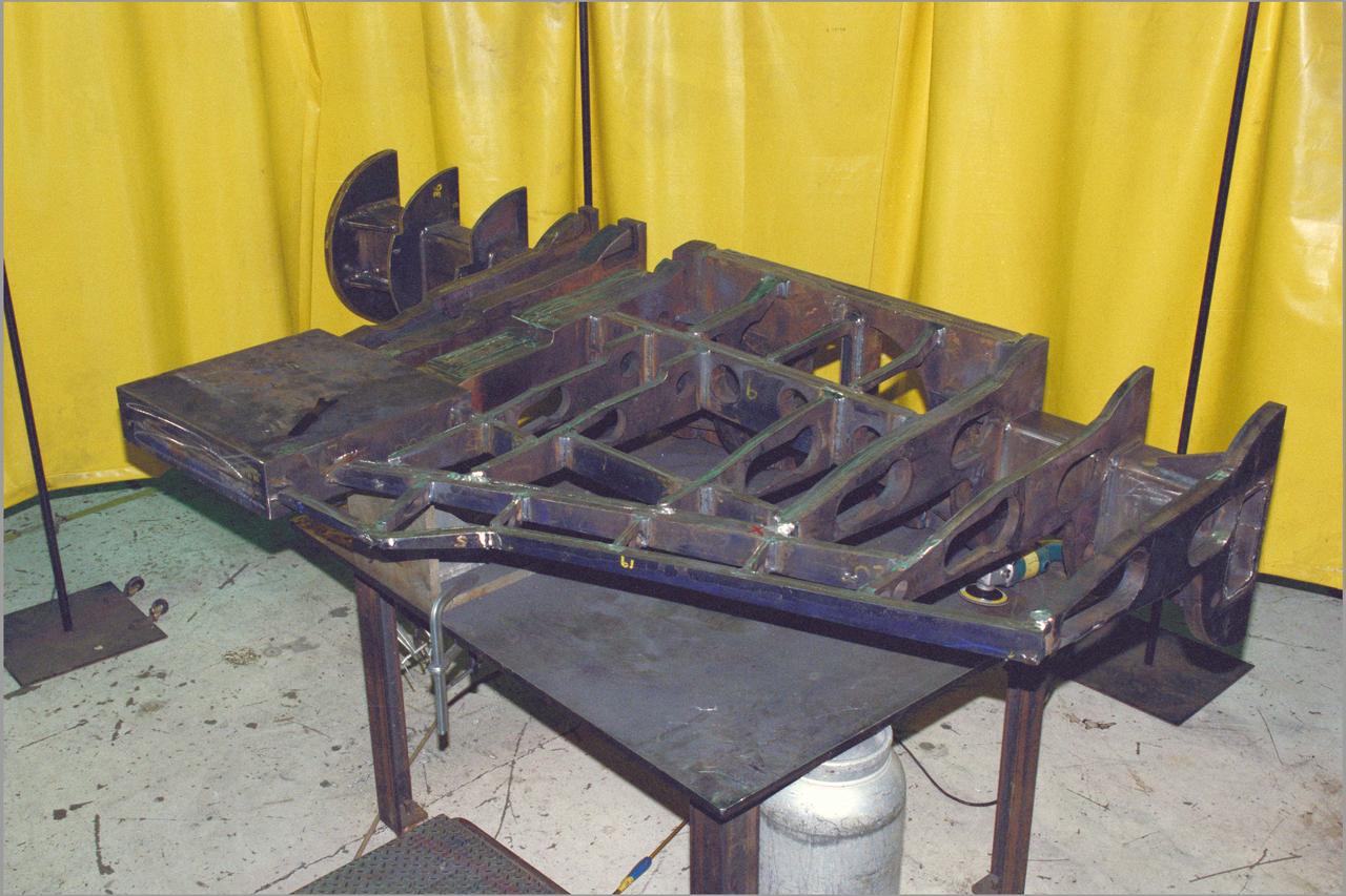
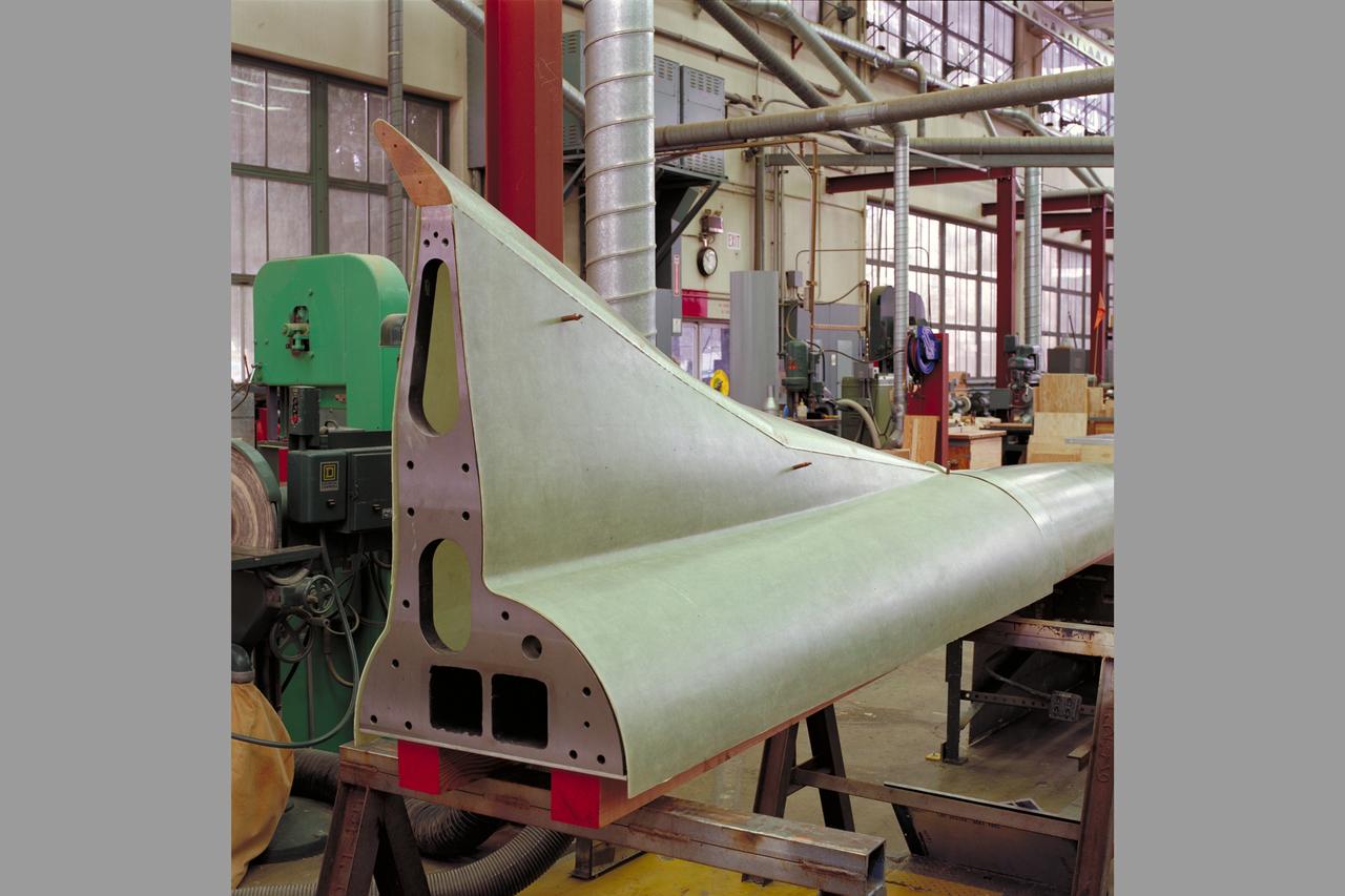
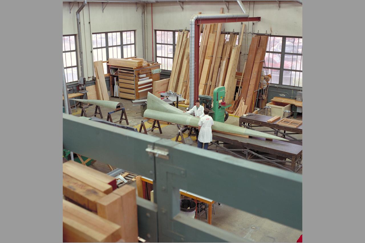
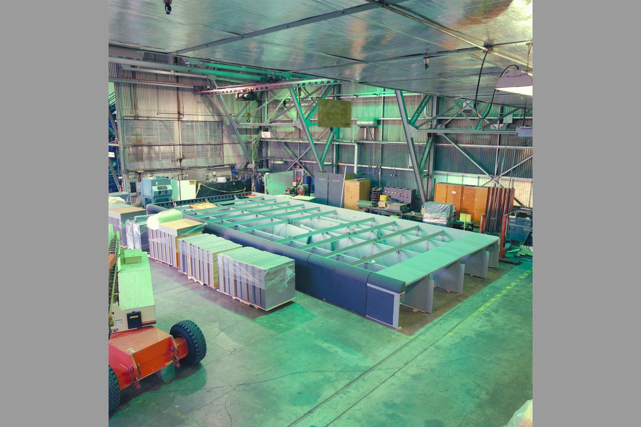
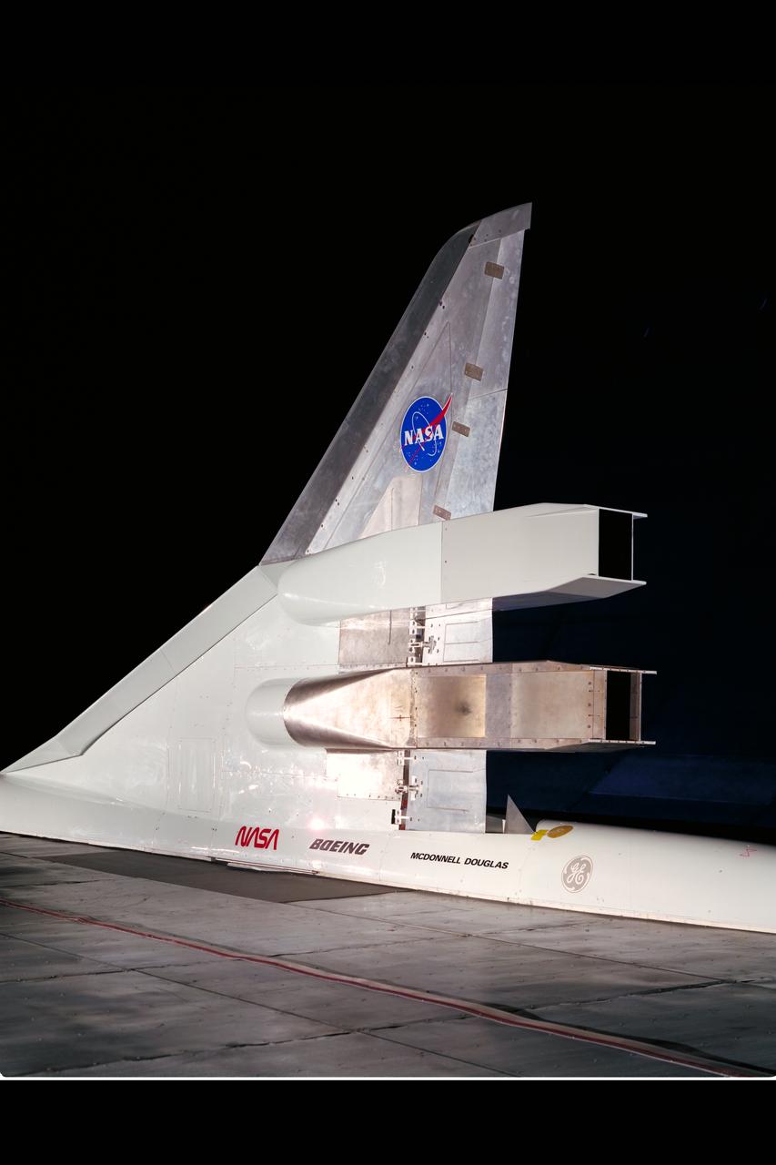
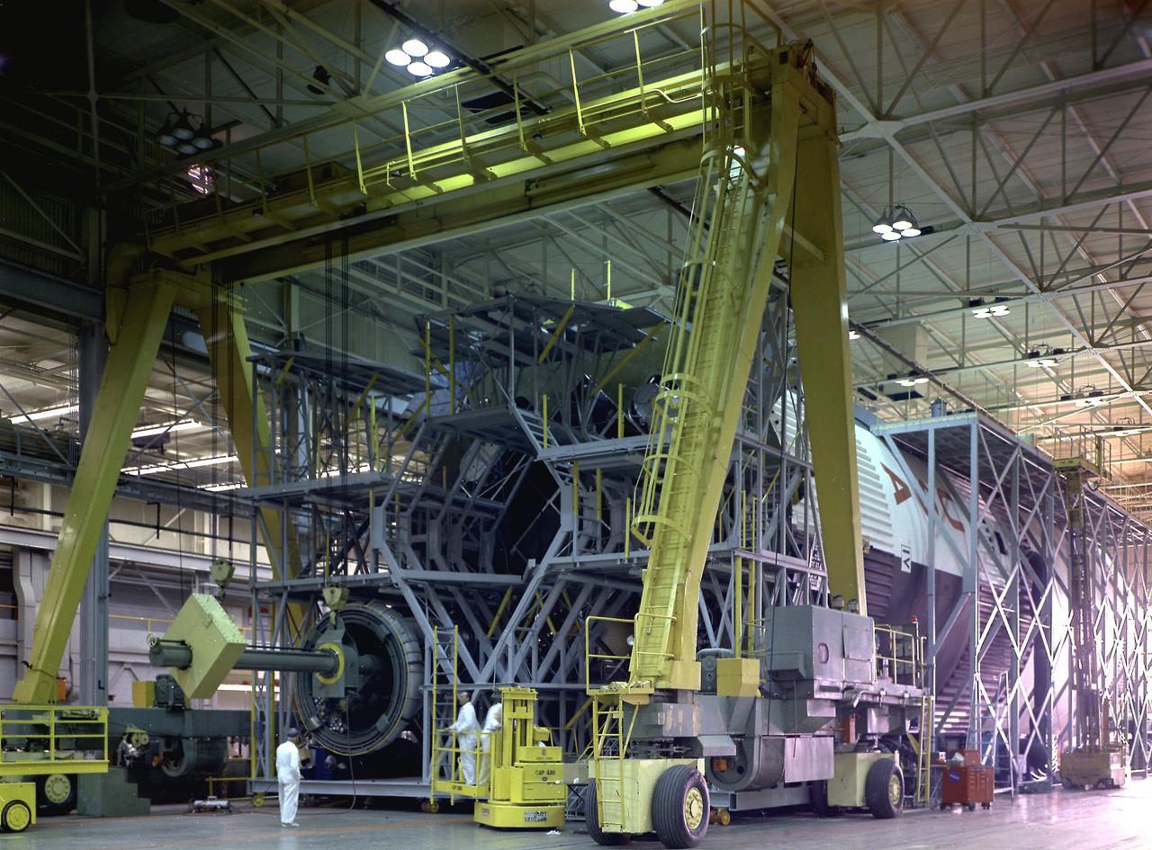
HEAT Project (High-Lift Engine Aeroacustics Technology) model assembly
HEAT Project (High-Lift Engine Aeroacustics Technology) model assembly
HEAT Project (High-Lift Engine Aeroacustics Technology) model assembly
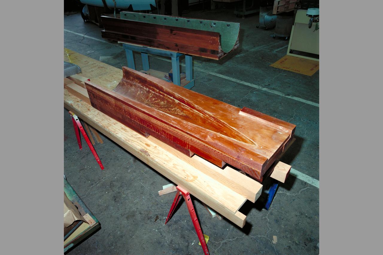
HEAT Project (High-Lift Engine Aeroacustics Technology) model assembly
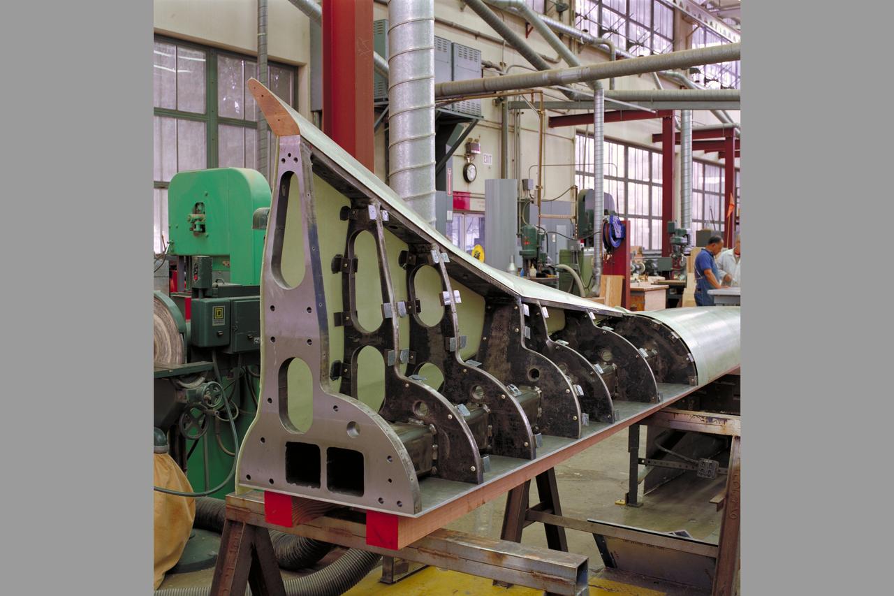
HEAT Project (High-Lift Engine Aeroacustics Technology) model assembly
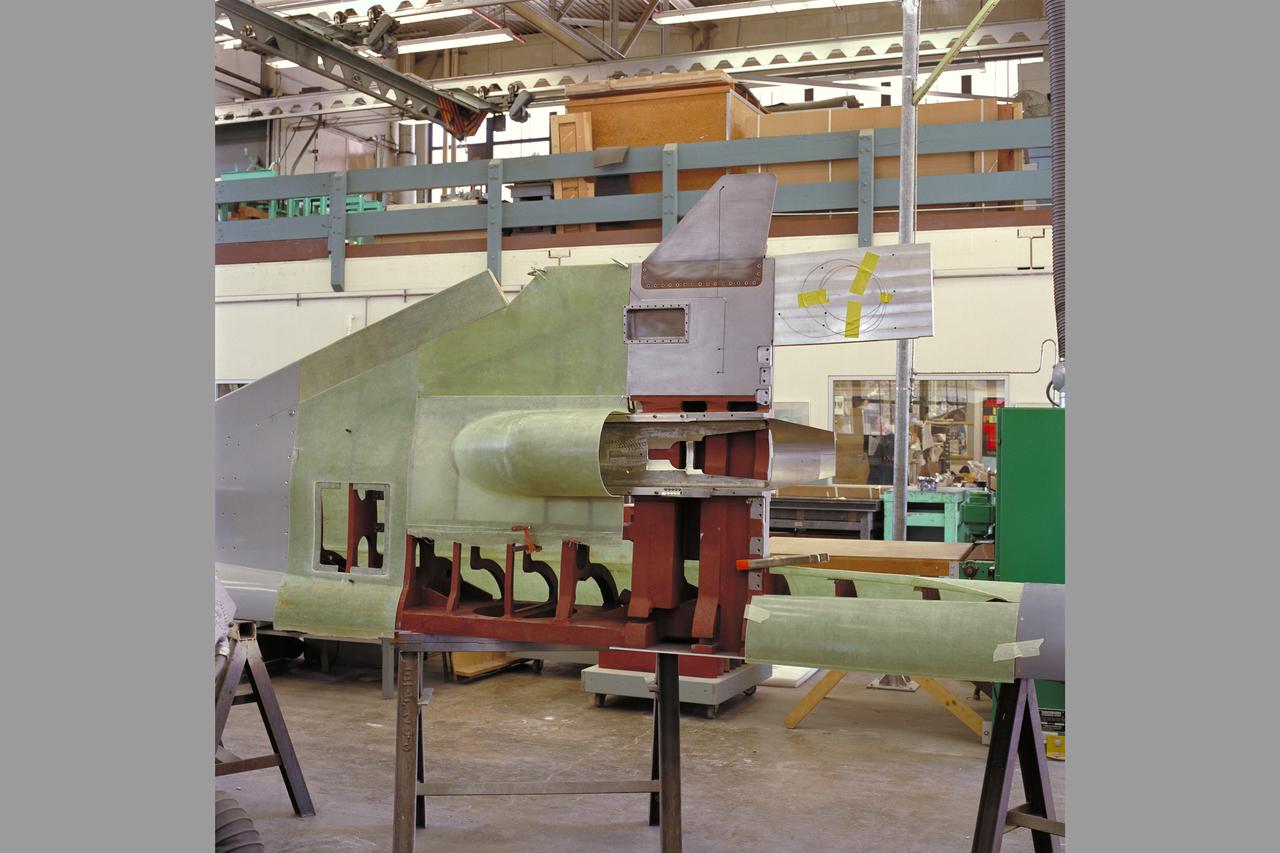
HEAT Project (High-Lift Engine Aeroacustics Technology) model assembly
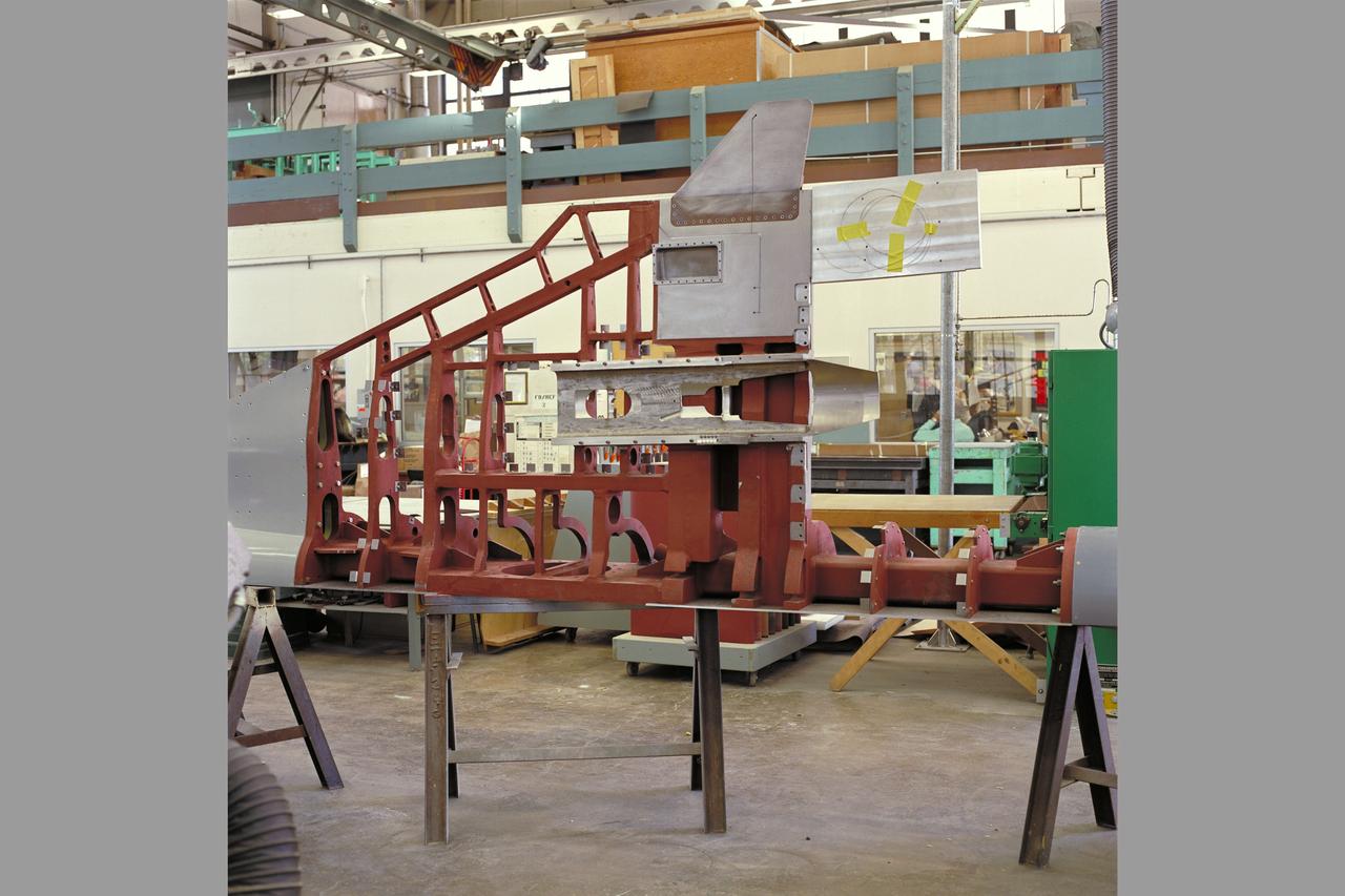
HEAT Project (High-Lift Engine Aeroacustics Technology) model assembly
HEAT Project (High-Lift Engine Aeroacustics Technology) model assembly

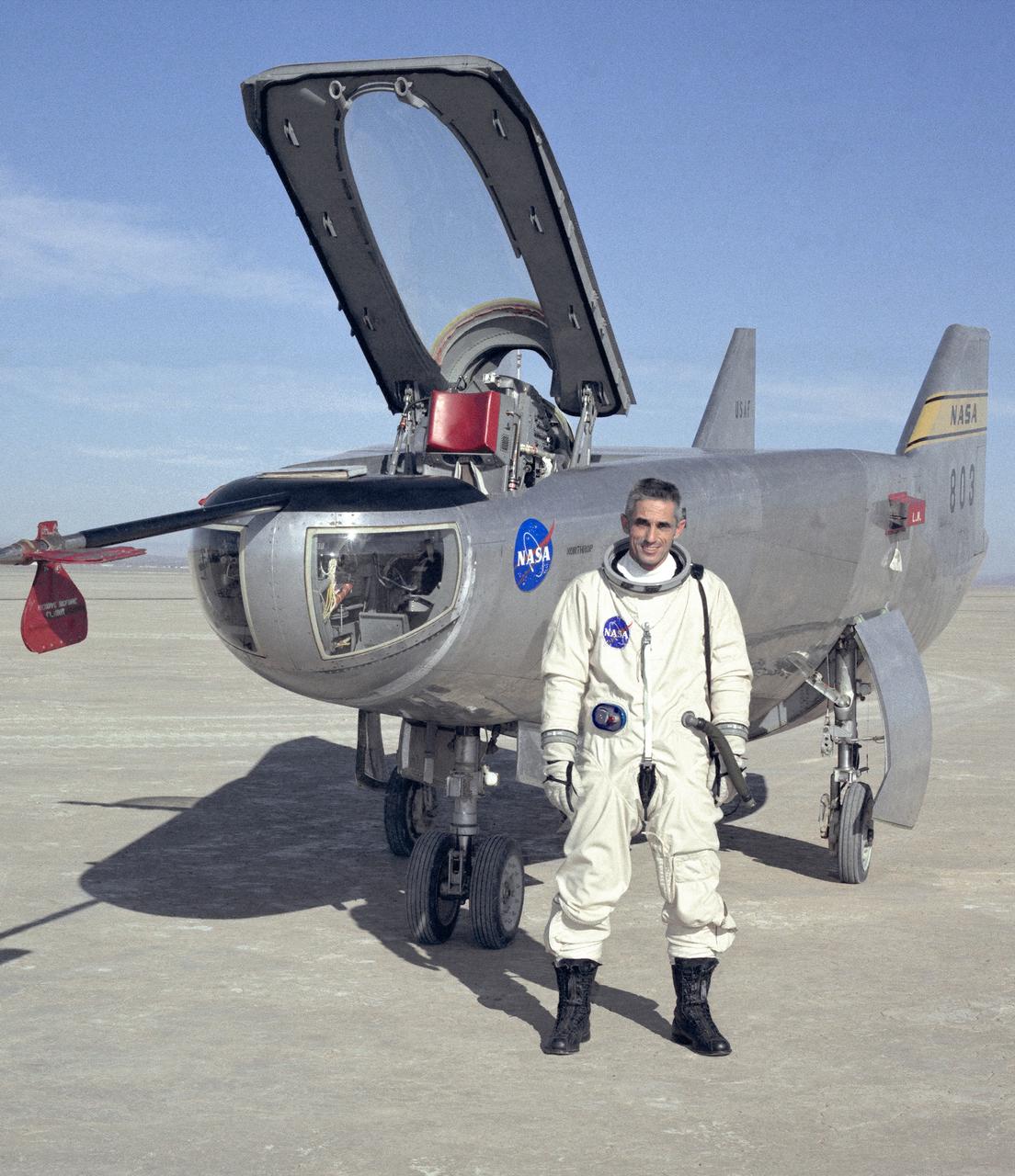
NASA research pilot Bill Dana stands in front of the HL-10 Lifting Body following his first glide flight on April 25, 1969. Dana later retired as Chief Engineer at NASA's Dryden Flight Research Center, (called the NASA Flight Research Center in 1969). Prior to his lifting body assignment, Dana flew the X-15 research airplane. He flew the rocket-powered aircraft 16 times, reaching a top speed of 3,897 miles per hour and a peak altitude of 310,000 feet (almost 59 miles high).
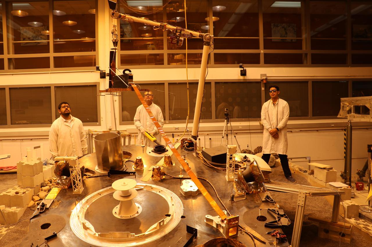
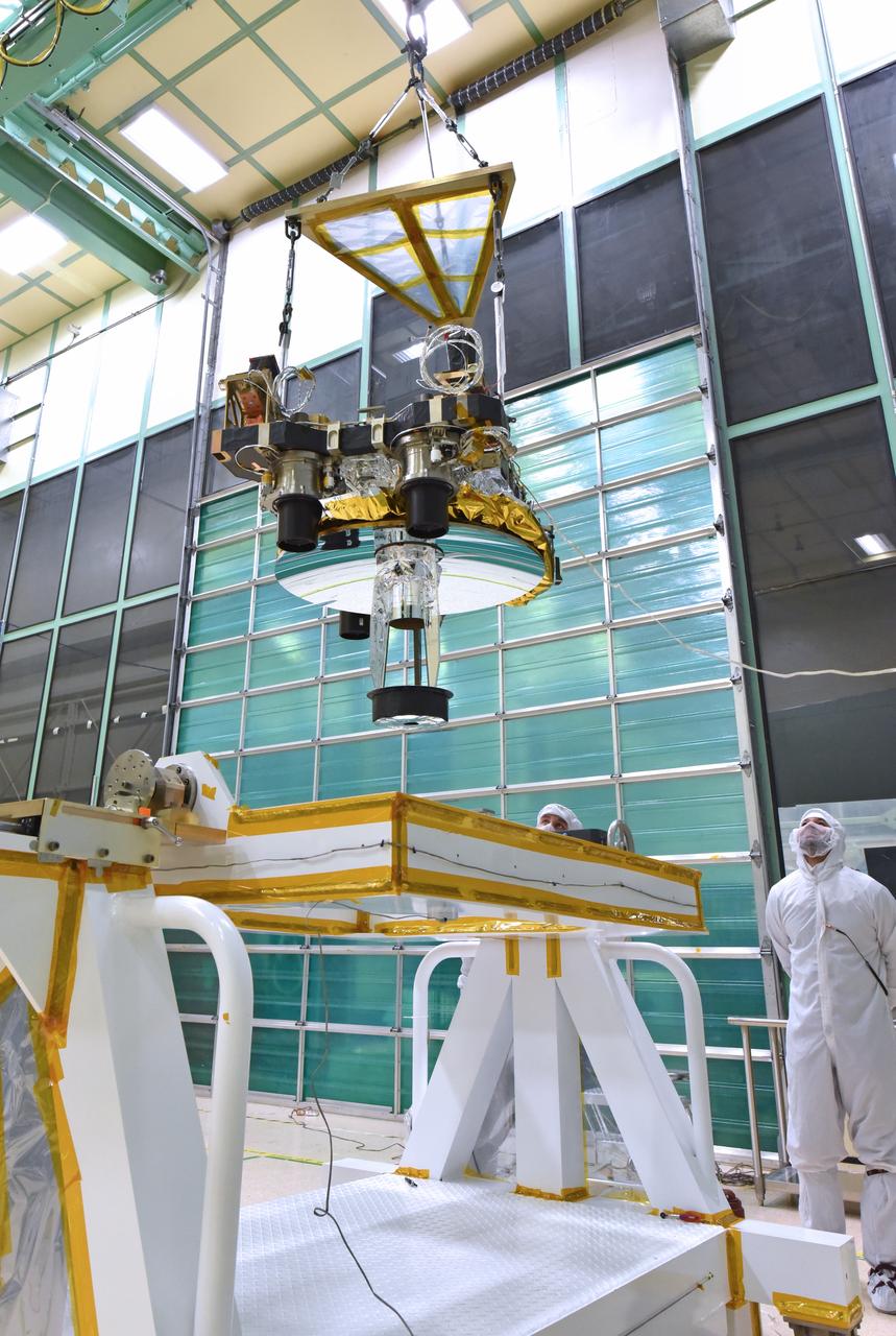
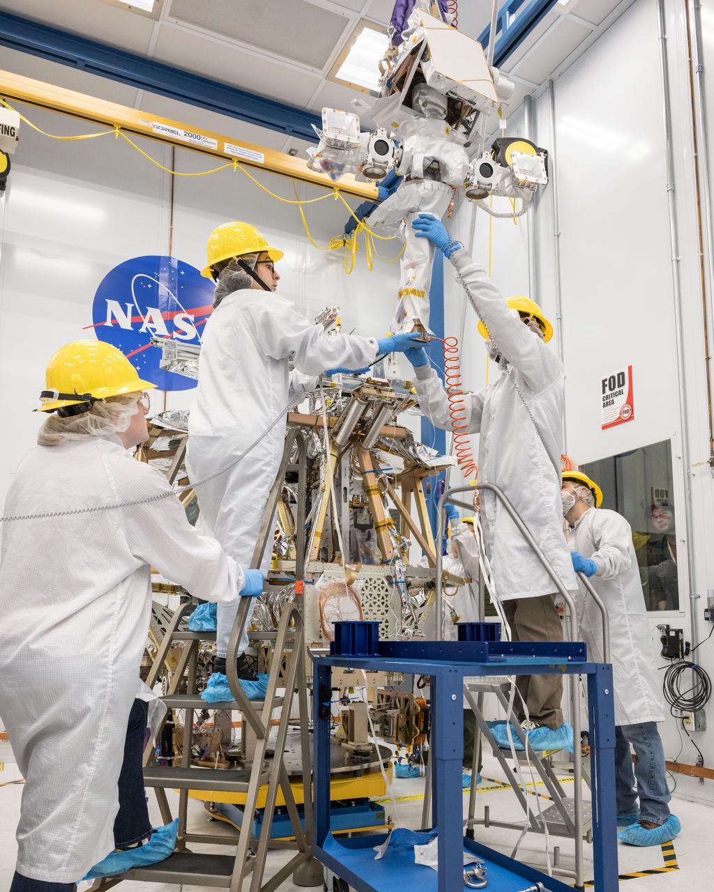
An engineering version of the robotic arm on NASA's InSight mission lifts the engineering version of the Heat Flow and Physical Properties Probe (HP3) at NASA's Jet Propulsion Laboratory. This test was conducted by InSight team members in a Mars-like environment, including reddish lighting, to simulate conditions InSight will encounter on the Red Planet. The orange tape-like tail behind HP3 is a tether that connects the HP3 support structure to the instrument's back-end electronics box on the lander. https://photojournal.jpl.nasa.gov/catalog/PIA22807
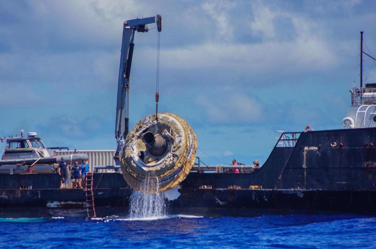
Hours after its successful engineering flight, the first test vehicle for NASA Low-Density Supersonic Decelerator project is lifted aboard the recovery vessel Kahana.
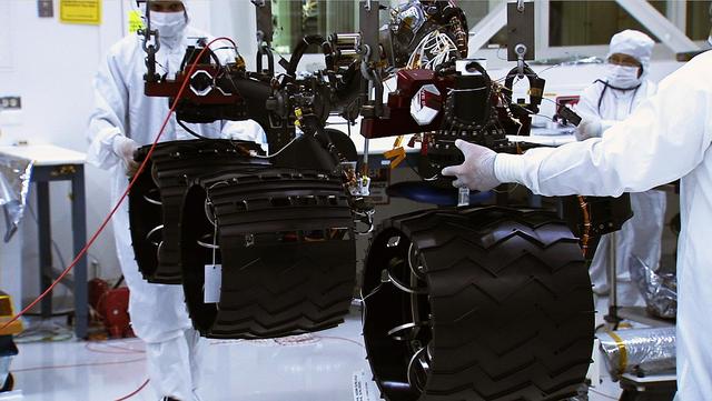
In the middle of this image, three wheels are shown raised by a lift, with engineers on both sides of the wheels in the cleanroom, where NASA Curiosity rover is being assembled.
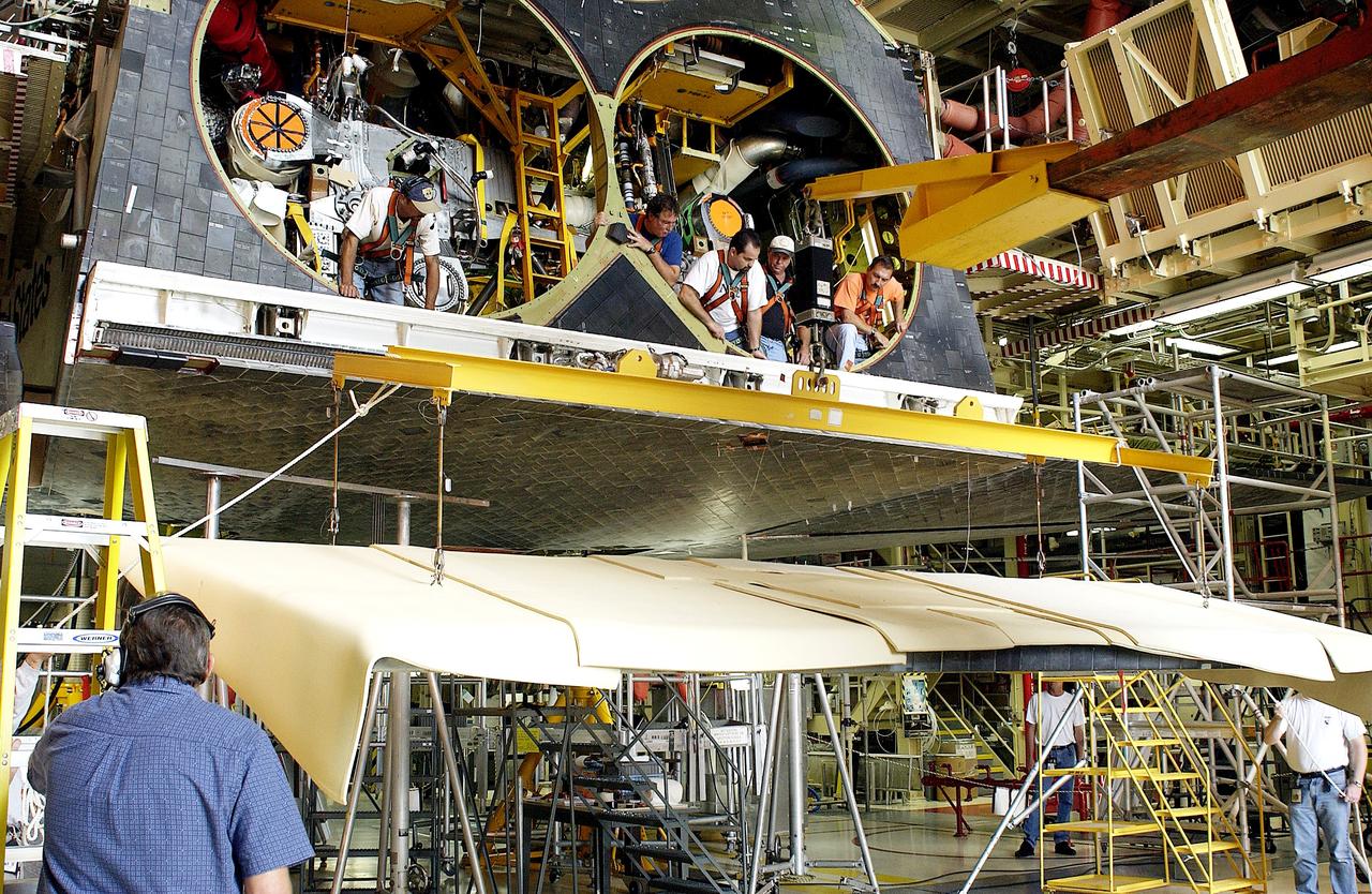
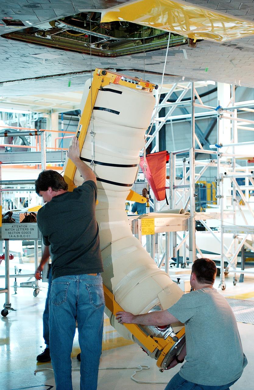
KENNEDY SPACE CENTER, FLA. - In the Orbiter Processing Facility, workers look down from spaces allotted for the main engines as the rear body flap is lifted for installation on the orbiter Discovery. The body flap, which is temporarily under protective covering, attaches below the main engines.
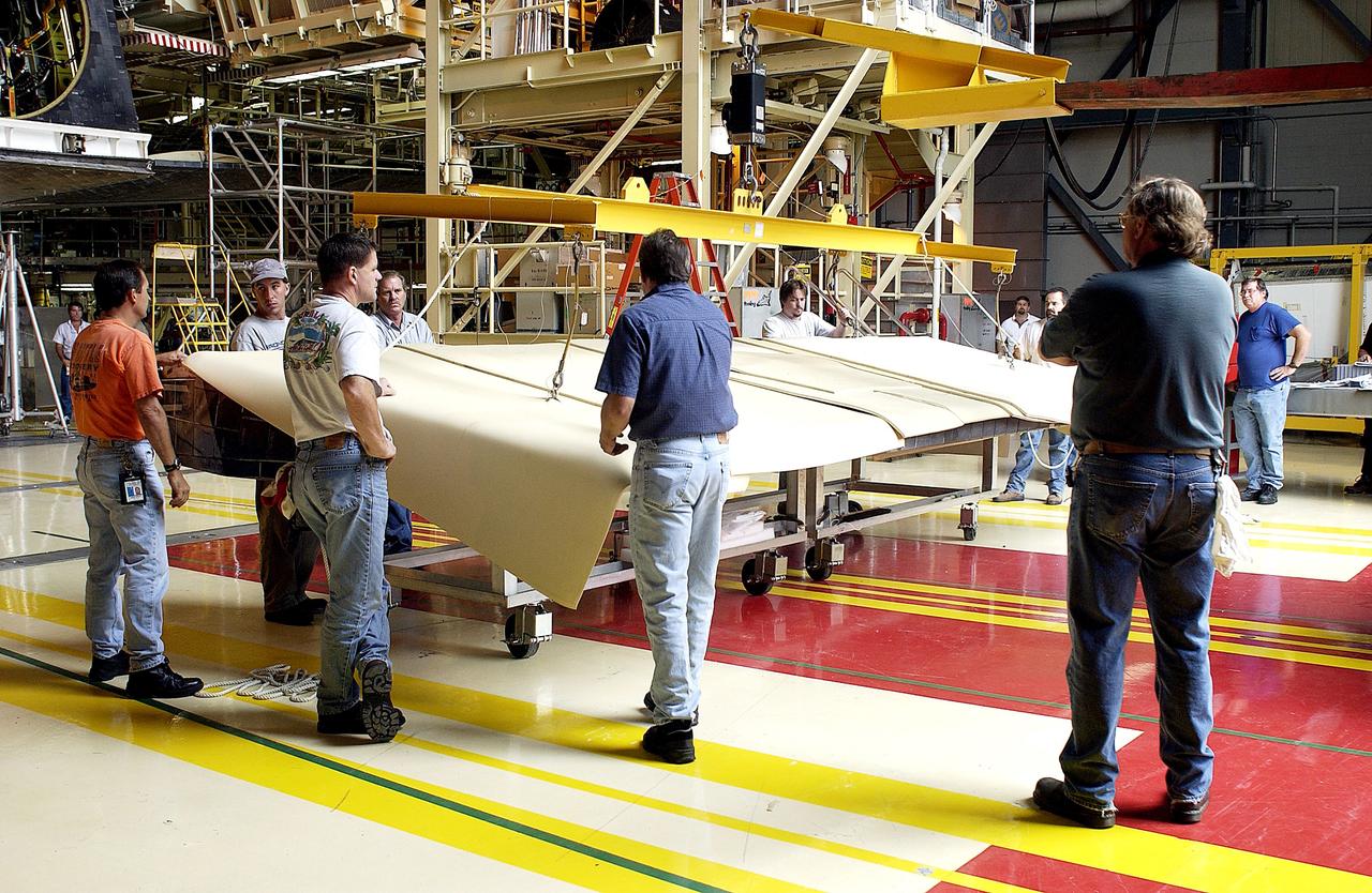
KENNEDY SPACE CENTER, FLA. - Workers in the Orbiter Processing Facility get ready to lift and install the rear body flap on orbiter Discovery. The body flap, which is temporarily under protective covering, attaches below the main engines.
KENNEDY SPACE CENTER, FLA. - Workers in the Orbiter Processing Facility get ready to lift and install the rear body flap on orbiter Discovery. The body flap, which is temporarily under protective covering, attaches below the main engines.
KENNEDY SPACE CENTER, FLA. - Workers in the Orbiter Processing Facility get ready to lift and install the rear body flap on orbiter Discovery. The body flap, which is temporarily under protective covering, attaches below the main engines.
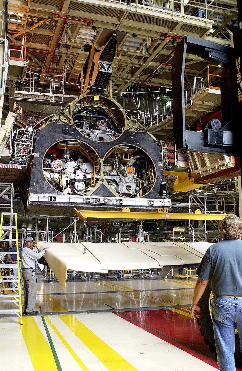
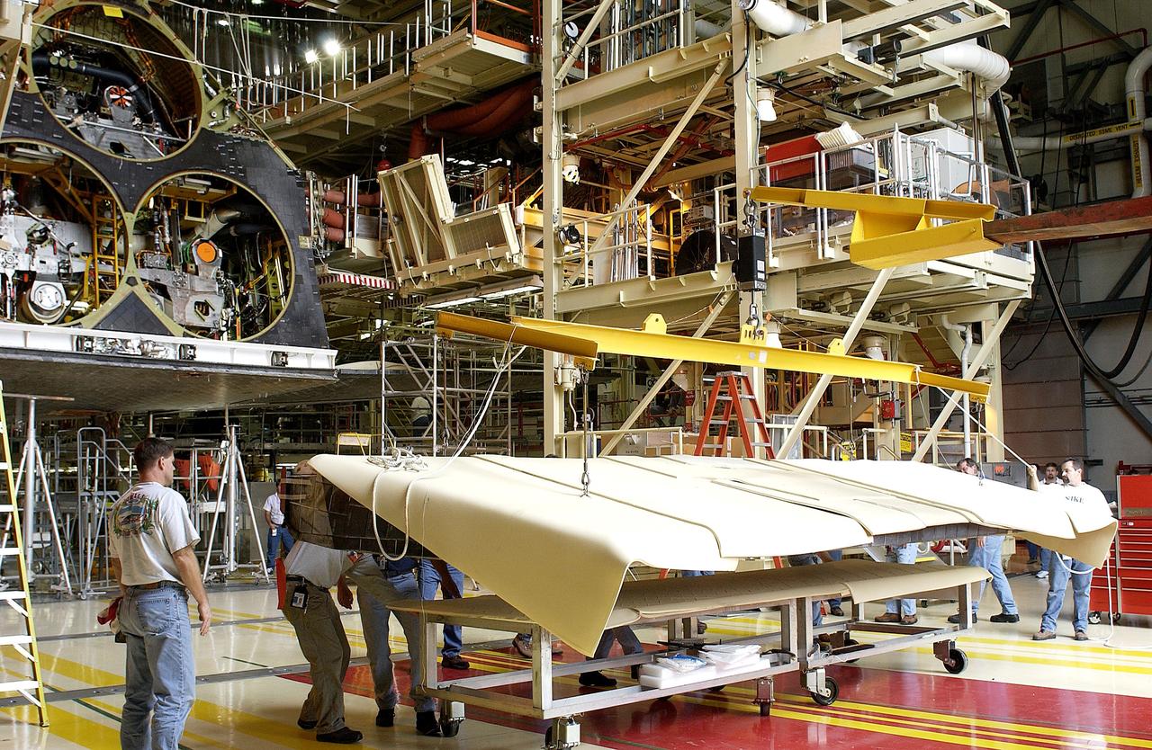
KENNEDY SPACE CENTER, FLA. - In the Orbiter Processing Facility, the rear body flap is lifted into place on the orbiter Discovery. The body flap, which is temporarily under protective covering, attaches below the main engines.
NASA research pilot John A. Manke is seen here in front of the M2-F3 Lifting Body. Manke was hired by NASA on May 25, 1962, as a flight research engineer. He was later assigned to the pilot's office and flew various support aircraft including the F-104, F5D, F-111 and C-47. After leaving the Marine Corps in 1960, Manke worked for Honeywell Corporation as a test engineer for two years before coming to NASA. He was project pilot on the X-24B and also flew the HL-10, M2-F3, and X-24A lifting bodies. John made the first supersonic flight of a lifting body and the first landing of a lifting body on a hard surface runway. Manke served as Director of the Flight Operations and Support Directorate at the Dryden Flight Research Center prior to its integration with Ames Research Center in October 1981. After this date John was named to head the joint Ames-Dryden Directorate of Flight Operations. He also served as site manager of the NASA Ames-Dryden Flight Research Facility. John is a member of the Society of Experimental Test Pilots. He retired on April 27, 1984.
Engineers at NASA's Jet Propulsion Laboratory lift the Mars 2020 rover's bit carousel out of its storage container. The bit carousel is a mechanism that is at the heart of the rover's Sample Caching System. The image was taken on Aug. 5, 2019, in the Spacecraft Assembly Facility's High Bay 1 at JPL. https://photojournal.jpl.nasa.gov/catalog/PIA23320
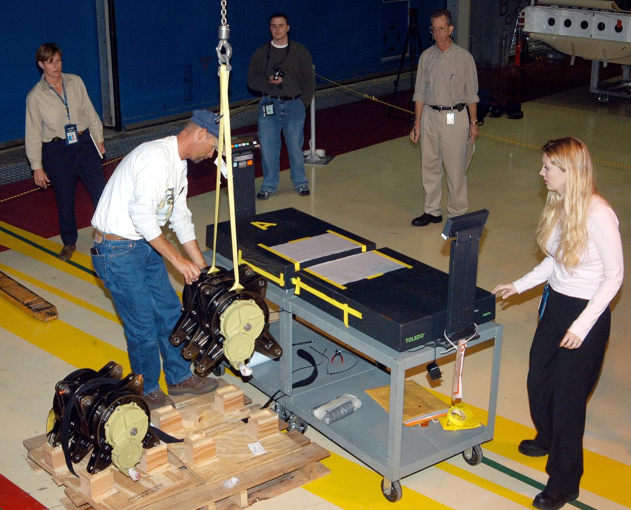
KENNEDY SPACE CENTER, FLA. - Workers in the Orbiter Processing Facility stand by while another guides the lifting of one of two rudder speed brake actuators onto a table to measure the alignment of its bearings. The actuators move an orbiter’s rudder, speed brake, elevons and main engines during flight.
Here is a close-up of the GE F414 engine, from the aft deck or rear, before the tail section of the X-59 is lifted into place and attached to the aircraft. The aft deck helps control the shockwaves at the end of the aircraft and reduce the noise of a sonic boom to more of a sonic thump.
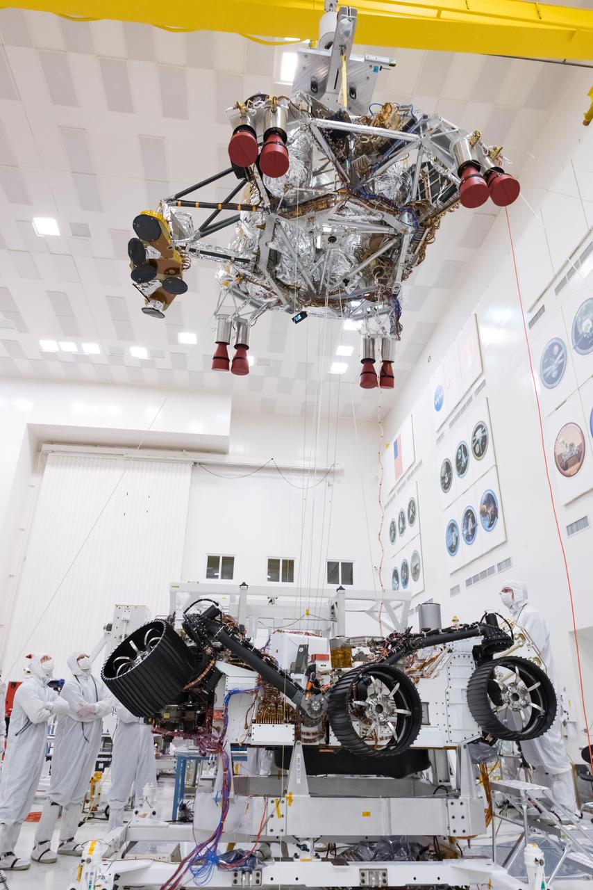
In this picture from Sept. 28, 2019, engineers and technicians working on the Mars 2020 spacecraft at NASA's Jet Propulsion Laboratory in Pasadena, California, look on as a crane lifts the rocket-powered descent stage away from the rover after a test. https://photojournal.jpl.nasa.gov/catalog/PIA23466
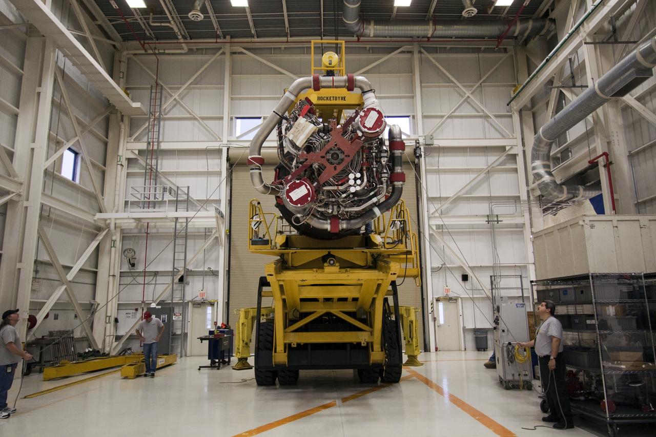
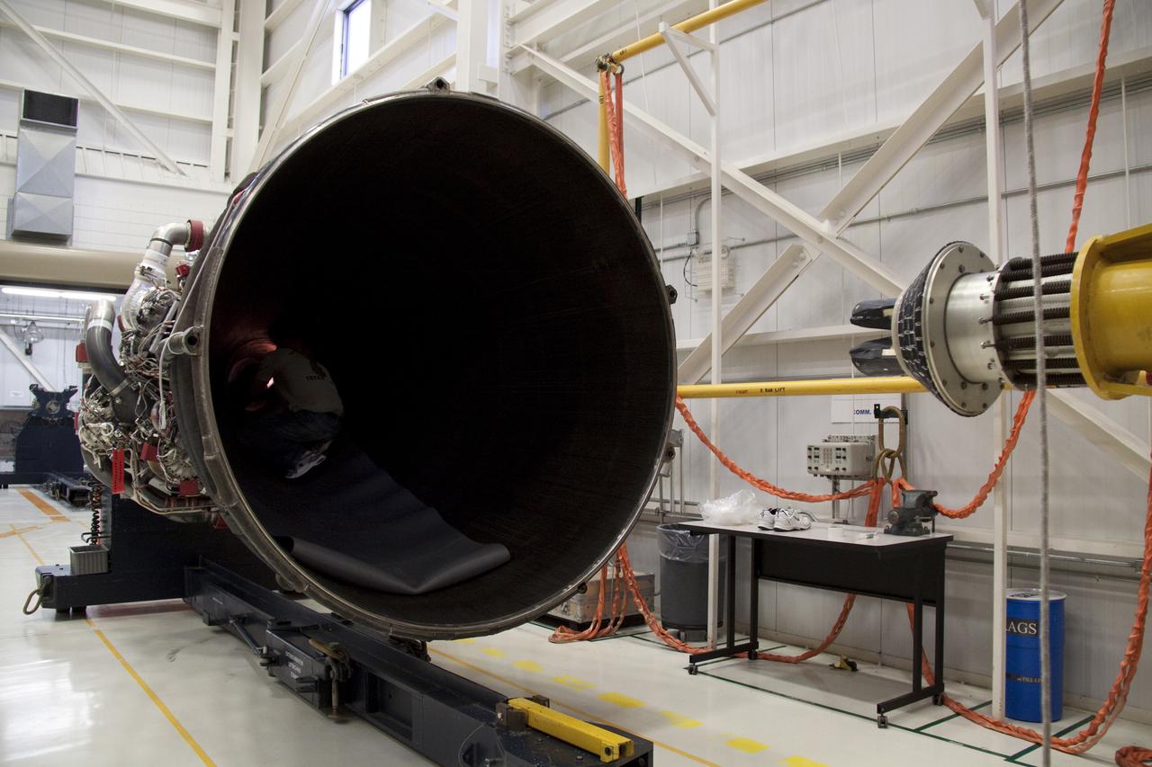
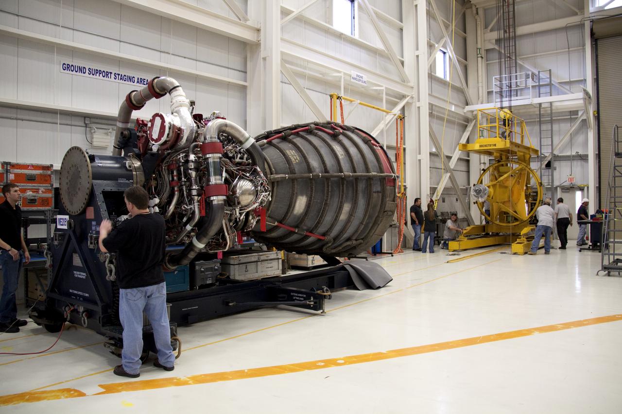
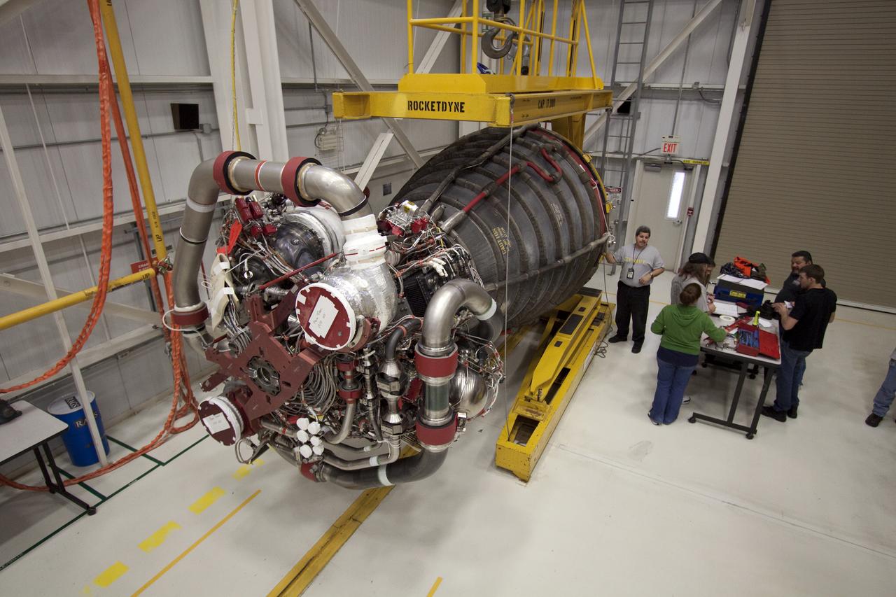
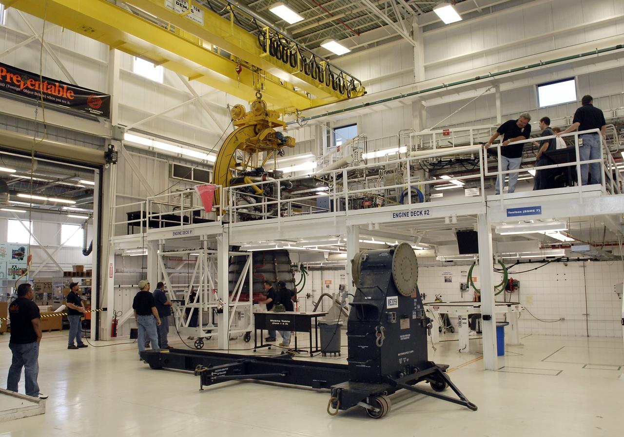
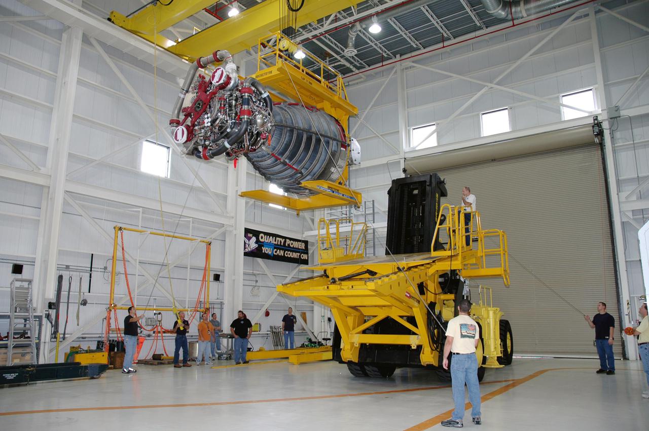
STS-132 ATLANTIS - ENGINE #2 LIFT TO TRANSPORTERAT ENGINE SHOP - XFER TO OPF-1 & INSTALL
STS-132 ATLANTIS - ENGINE #2 LIFT TO TRANSPORTERAT ENGINE SHOP - XFER TO OPF-1 & INSTALL
STS-132 ATLANTIS - ENGINE #2 LIFT TO TRANSPORTERAT ENGINE SHOP - XFER TO OPF-1 & INSTALL
STS-132 ATLANTIS - ENGINE #2 LIFT TO TRANSPORTERAT ENGINE SHOP - XFER TO OPF-1 & INSTALL
STS-132 ATLANTIS - ENGINE #2 LIFT TO TRANSPORTERAT ENGINE SHOP - XFER TO OPF-1 & INSTALL
STS-132 ATLANTIS - ENGINE #2 LIFT TO TRANSPORTERAT ENGINE SHOP - XFER TO OPF-1 & INSTALL
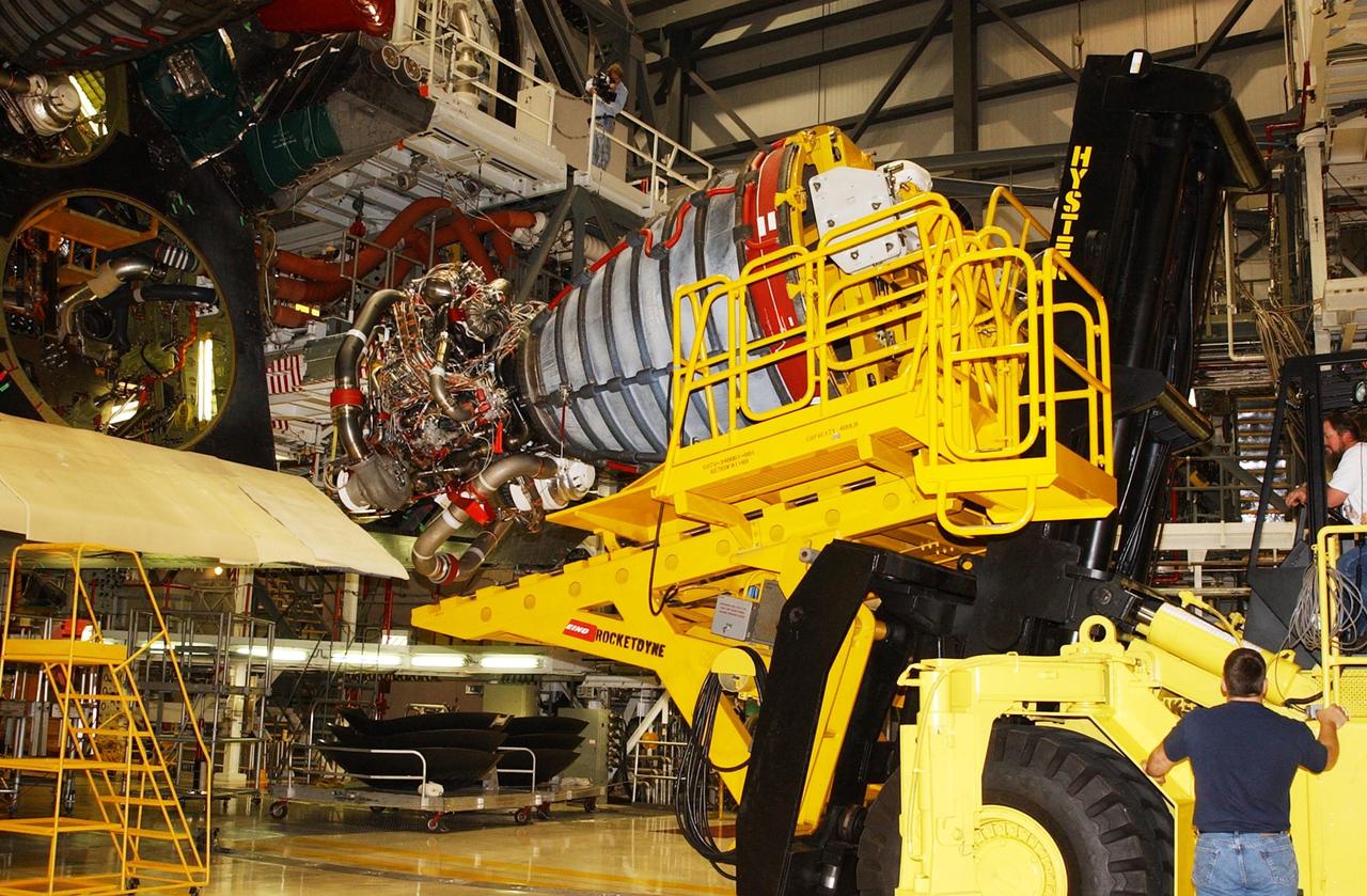
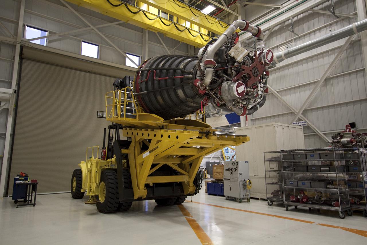
KENNEDY SPACE CENTER, FLA. -- In the Orbiter Processing Facility, an orbiter main engine is lifted by a new engine hyster, built by Rocketdyne, that is used to remove it from the orbiter. .
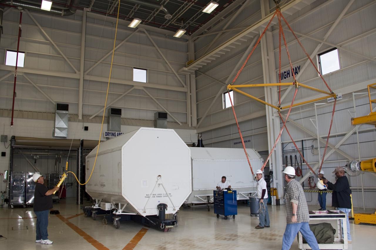
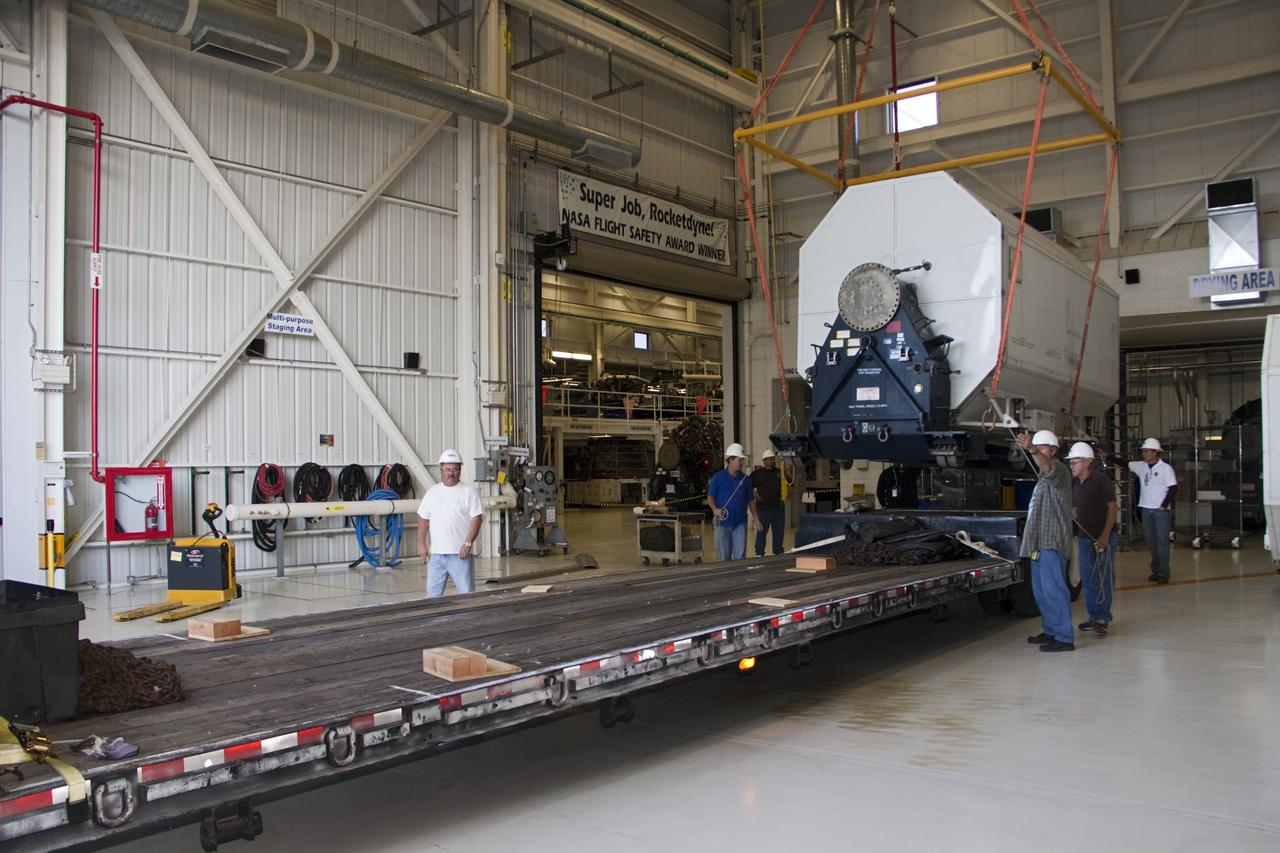
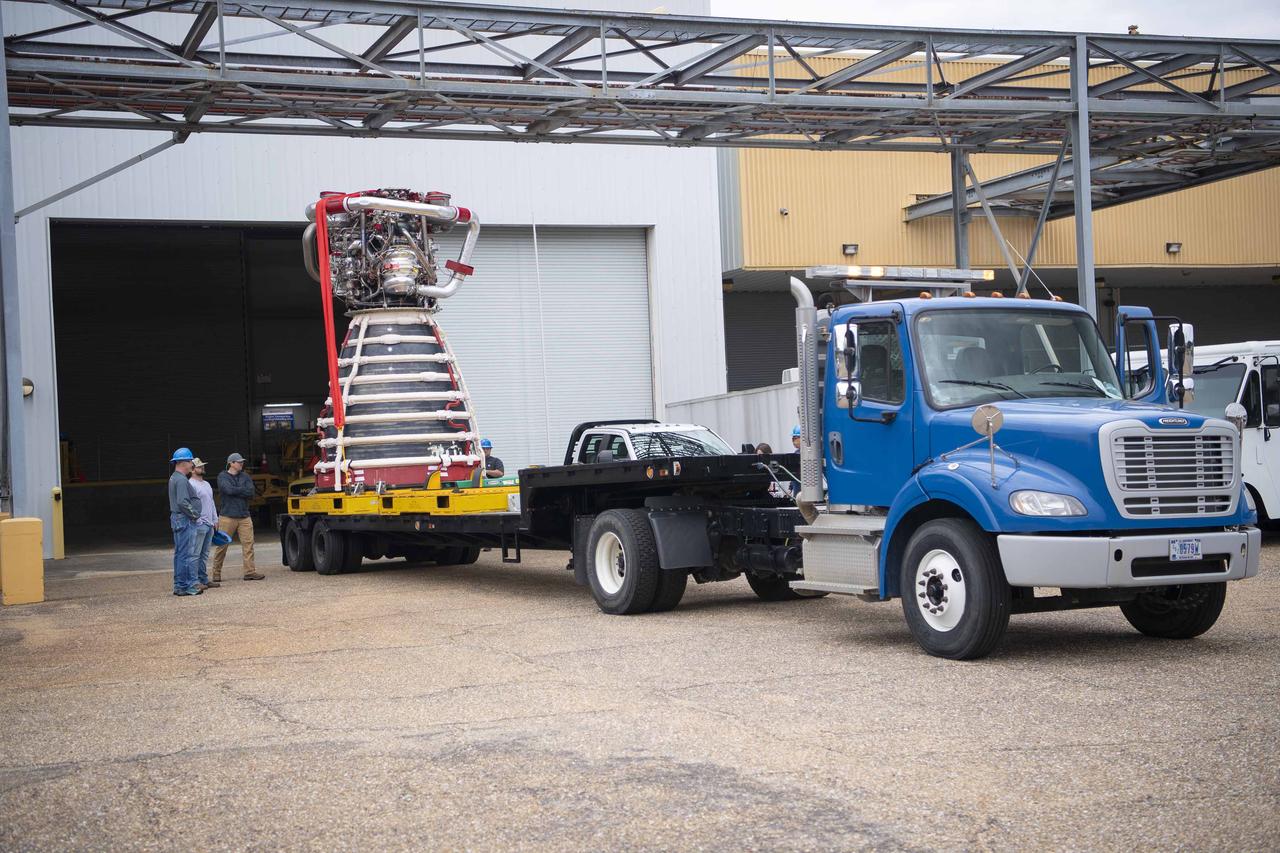
CAPE CANAVERAL, Fla. – In the Orbiter Processing Facility-3 engine shop at NASA's Kennedy Space Center in Florida, a transportation canister containing the last Pratt and Whitney Rocketdyne space shuttle main engine, or SSME, is lifted onto a flatbed truck for shipment to NASA's Stennis Space Center in Mississippi. The first two groups of engines were shipped from Kennedy to Stennis in November 2011 and January 2012 the remaining engines departed today. Altogether, 15 shuttle-era engines will be stored at Stennis for reuse on NASA’s Space Launch System heavy-lift rocket, under development. Photo credit: NASA/Dimitri Gerondidakis
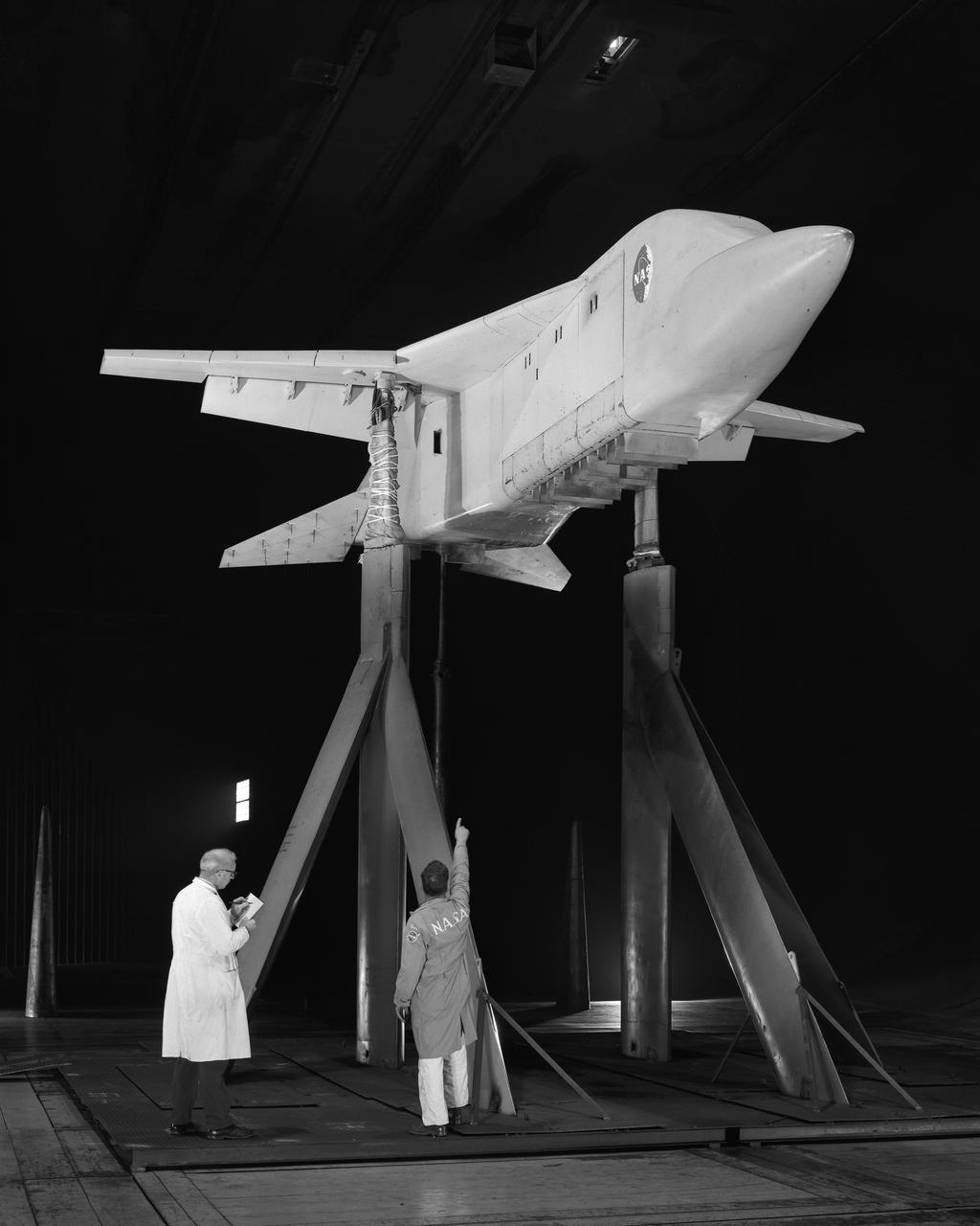
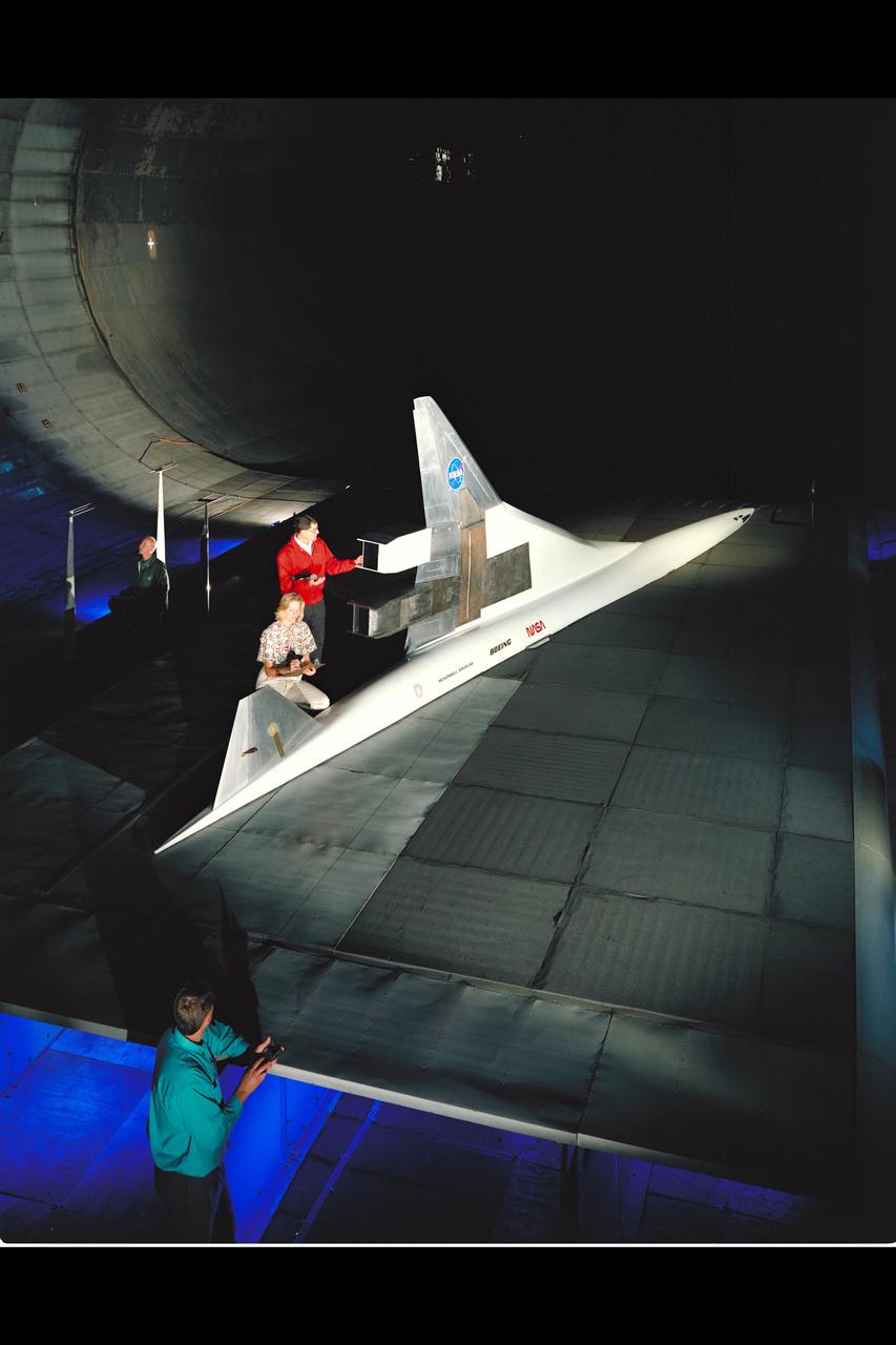
HEAT (High-Lift Engine Aeroacoustics Technology) Model test-596 in 40x80ft w.t.
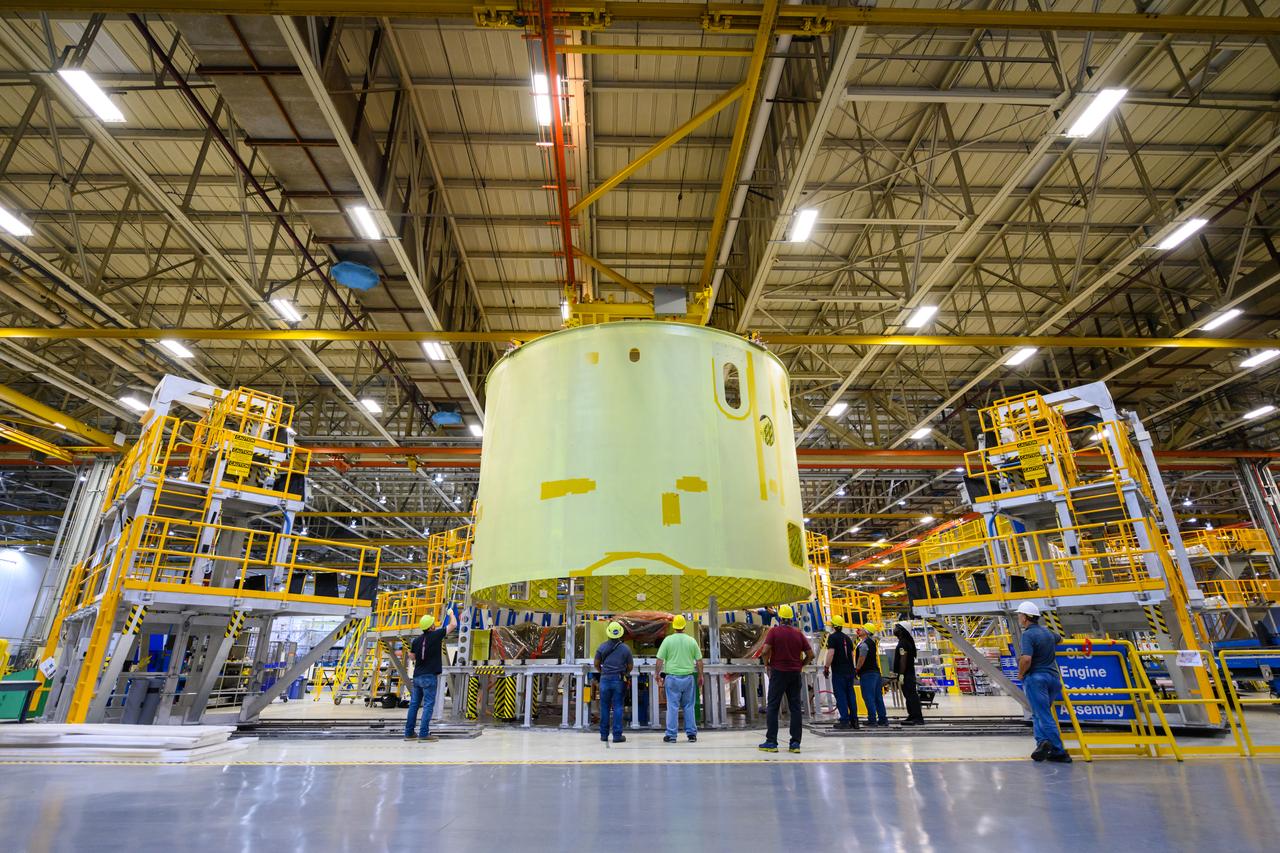
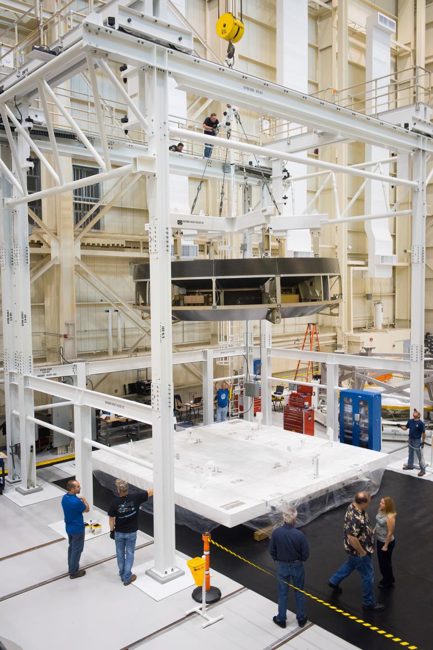
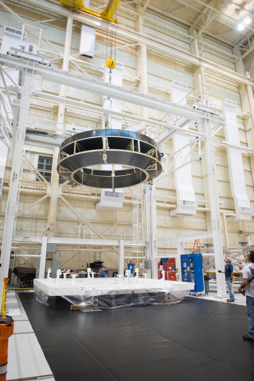
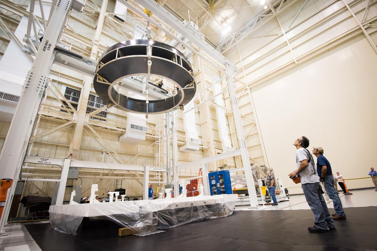
Space Launch System Corestage-2 Engine Section is lifted into a thrust structure tool at NASA's Michoud Assembly Facility.
Space Launch System Corestage-2 Engine Section is lifted into a thrust structure tool at NASA's Michoud Assembly Facility.
HEAT (High-Lift Engine Aeroacoustics Technology) Model test-596 in 40x80ft w.t.
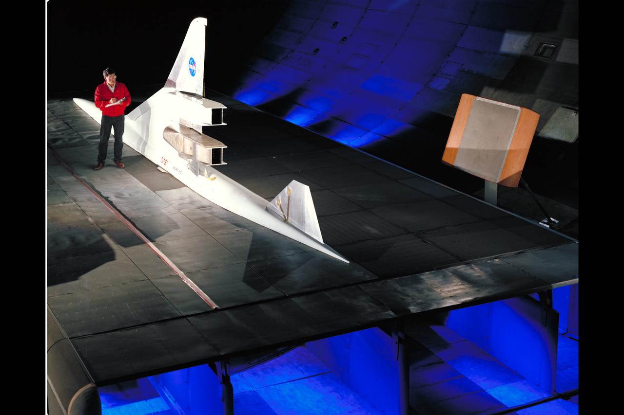
HEAT (High-Lift Engine Aeroacoustics Technology) Model test-596 in 40x80ft w.t. with Brian Smith
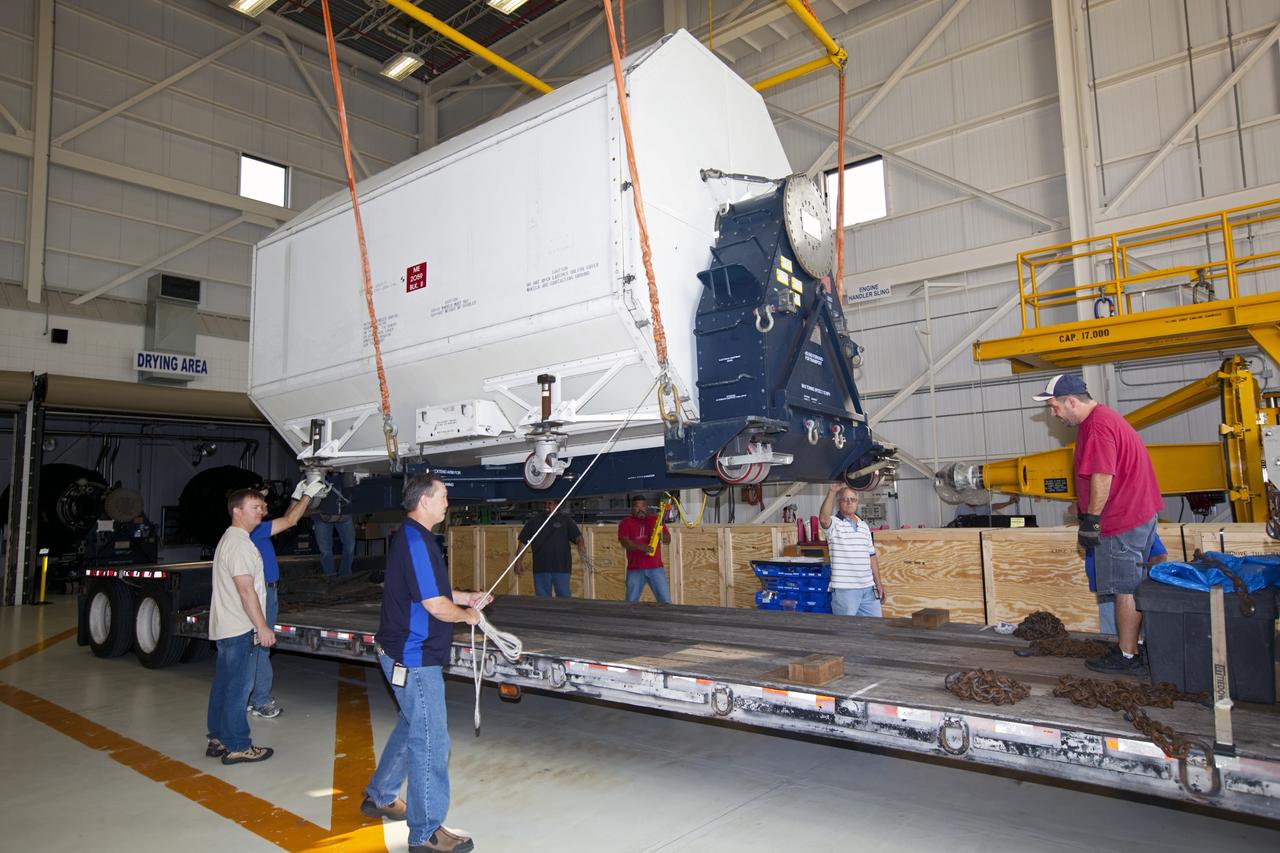
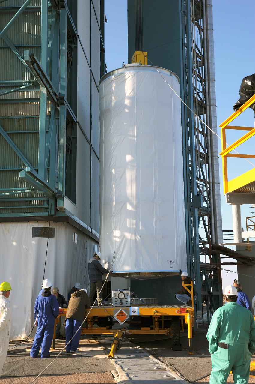
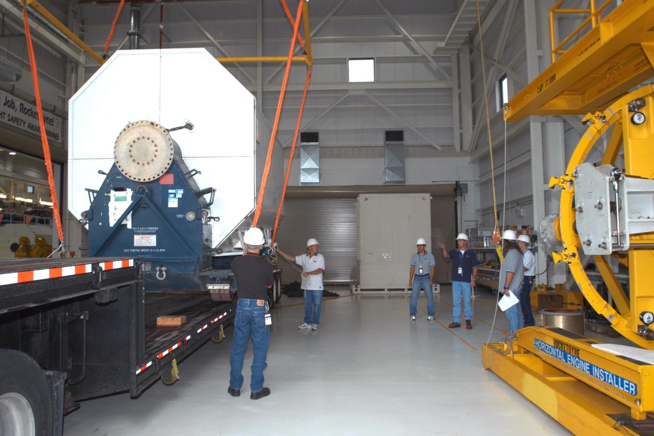
CAPE CANAVERAL, Fla. – In the Space Shuttle Main Engine Processing Facility at NASA’s Kennedy Space Center in Florida, preparations are under way to lift a transportation canister containing a Pratt & Whitney Rocketdyne space shuttle main engine (SSME) onto a flatbed trailer. This is the second of the 15 engines used during the Space Shuttle Program to be transported to NASA's Stennis Space Center in Mississippi. The engines will be stored at Stennis for future use on NASA's new heavy-lift rocket, the Space Launch System (SLS), which will carry NASA's new Orion spacecraft, cargo, equipment and science experiments to space. For more information, visit http://www.nasa.gov/shuttle. Photo credit: NASA/Jim Grossmann
CAPE CANAVERAL, Fla. – In the Space Shuttle Main Engine Processing Facility at NASA’s Kennedy Space Center in Florida, a transportation canister containing a Pratt & Whitney Rocketdyne space shuttle main engine (SSME) is lifted into position onto a flatbed trailer. This is the second of the 15 engines used during the Space Shuttle Program to be transported to NASA's Stennis Space Center in Mississippi. The engines will be stored at Stennis for future use on NASA's new heavy-lift rocket, the Space Launch System (SLS), which will carry NASA's new Orion spacecraft, cargo, equipment and science experiments to space. For more information, visit http://www.nasa.gov/shuttle. Photo credit: NASA/Jim Grossmann
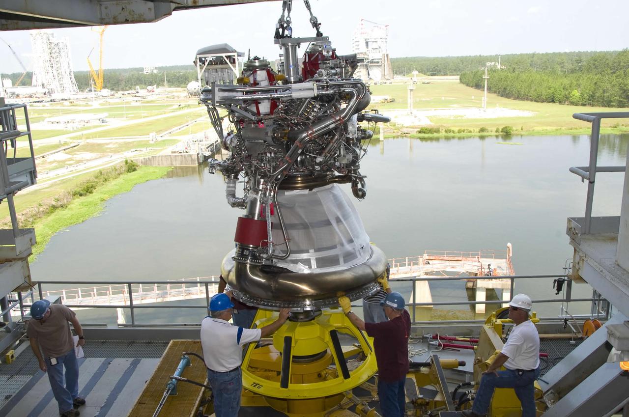
A J-2X next-generation rocket engine is lifted onto the A-2 Test Stand at Stennis Space Center. Testing of the engine began the following month. The engine is being developed for NASA by Pratt & Whitney Rocketdyne and could help carry humans beyond low-Earth orbit into deep space once more.
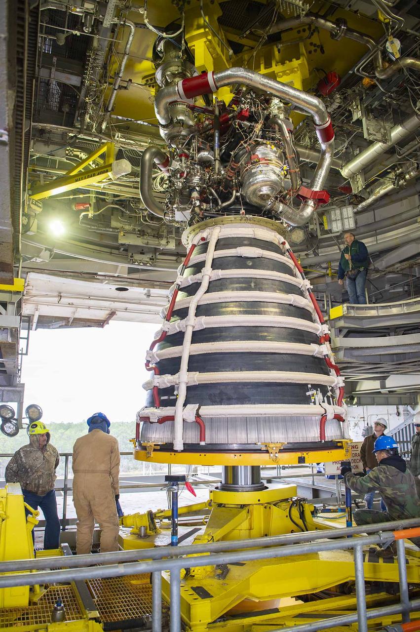
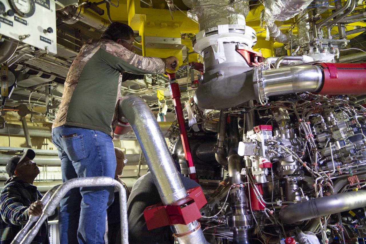
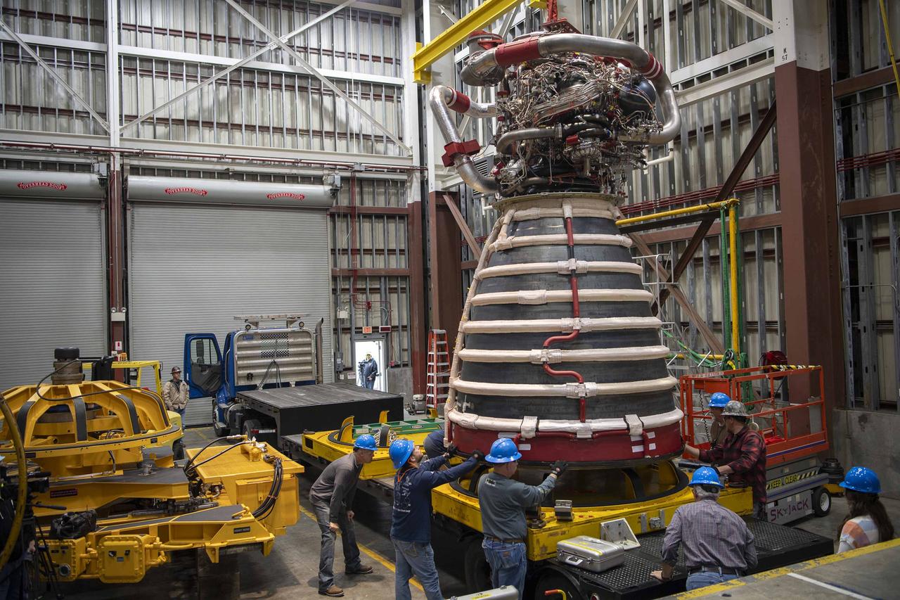
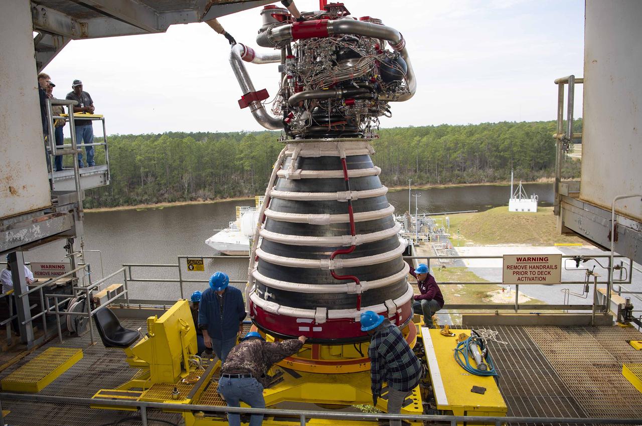
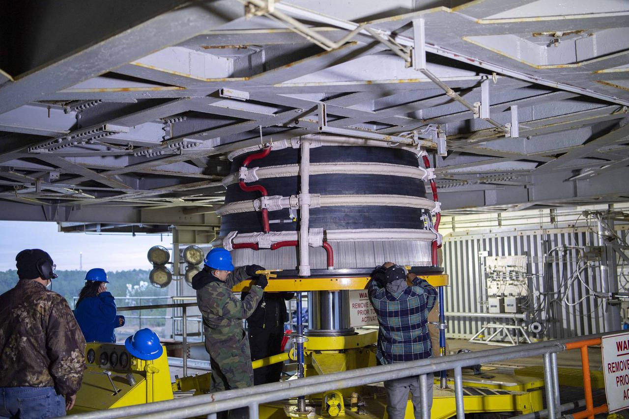
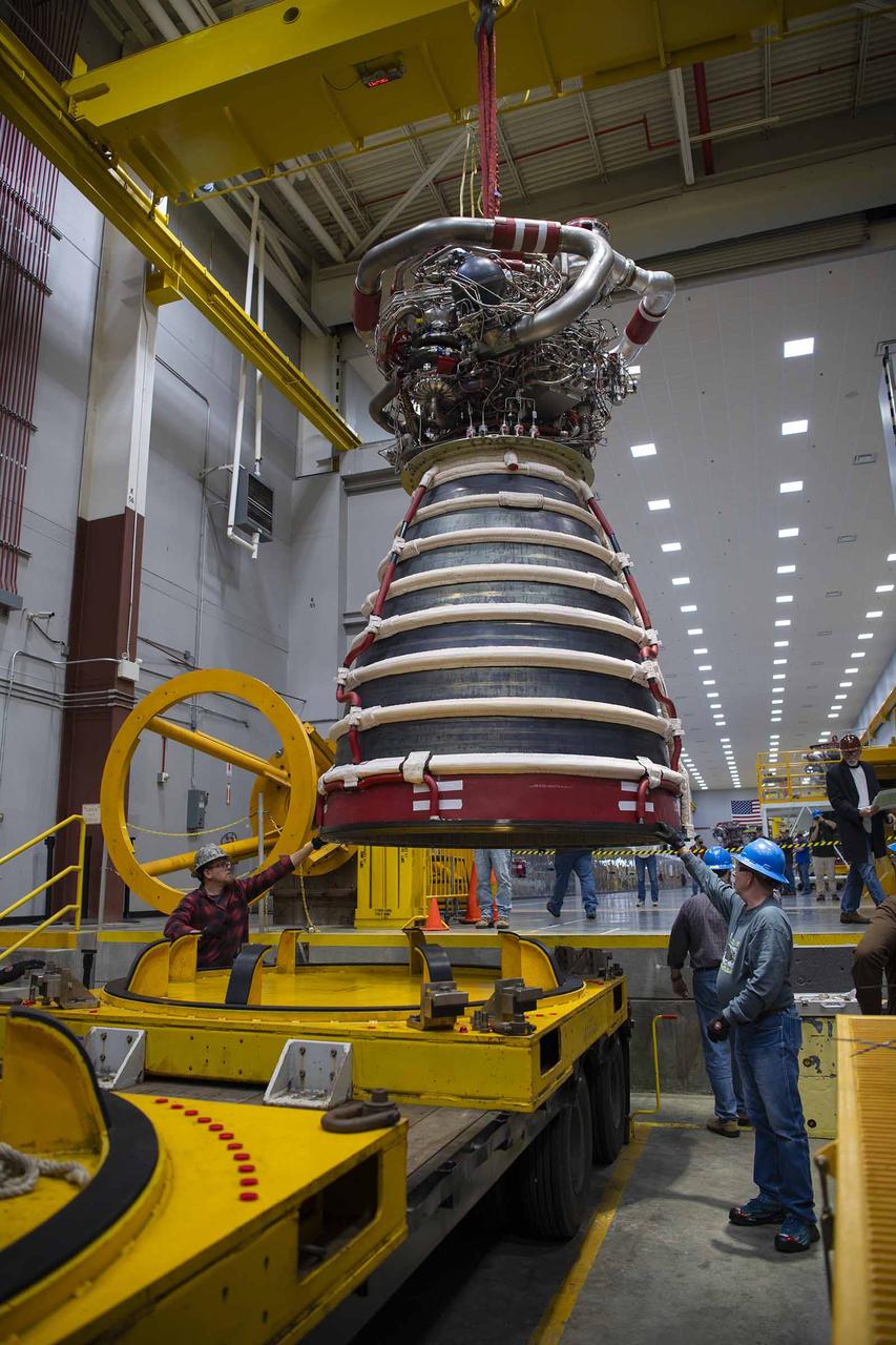
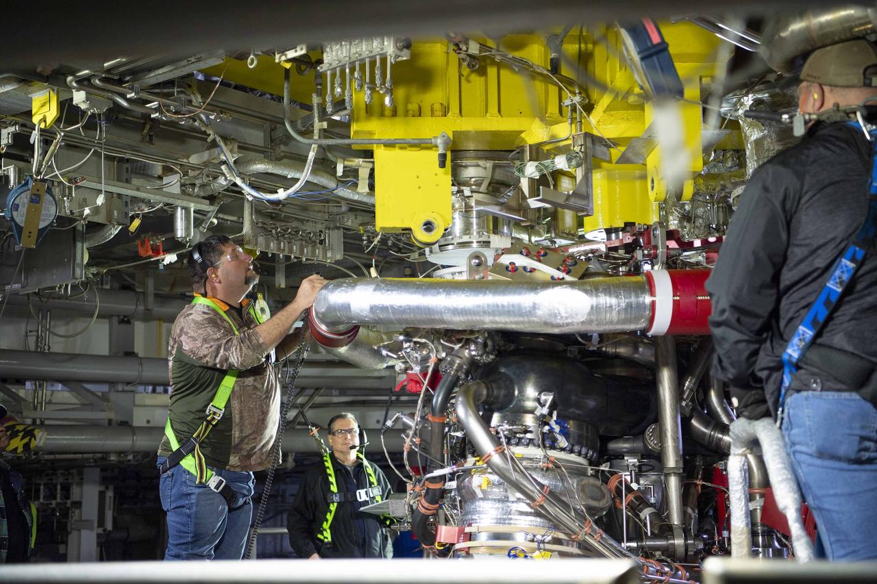
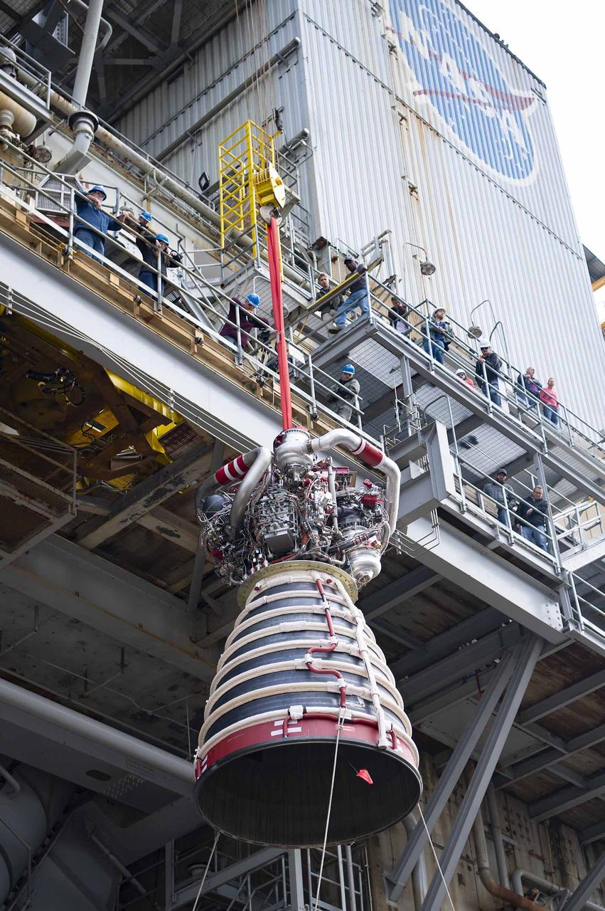
Teams at NASA’s Stennis Space Center deliver, lift, and install the first new production RS-25 engine on the Fred Haise Test Stand on Feb. 18.
Teams at NASA’s Stennis Space Center deliver, lift, and install the first new production RS-25 engine on the Fred Haise Test Stand on Feb. 18.
Teams at NASA’s Stennis Space Center deliver, lift, and install the first new production RS-25 engine on the Fred Haise Test Stand on Feb. 18.
Teams at NASA’s Stennis Space Center deliver, lift, and install the first new production RS-25 engine on the Fred Haise Test Stand on Feb. 18.
3/4 Low front view of fuselage and fan. Showing jet engine hanging below. Lift fan powered by jet exhaust.

Teams at NASA’s Stennis Space Center deliver, lift, and install the first new production RS-25 engine on the Fred Haise Test Stand on Feb. 18.
Teams at NASA’s Stennis Space Center deliver, lift, and install the first new production RS-25 engine on the Fred Haise Test Stand on Feb. 18.

Teams at NASA’s Stennis Space Center deliver, lift, and install the first new production RS-25 engine on the Fred Haise Test Stand on Feb. 18.
Teams at NASA’s Stennis Space Center deliver, lift, and install the first new production RS-25 engine on the Fred Haise Test Stand on Feb. 18.
HEAT (High-Lift Engine Aeroacoustics Technology) Model test-596 in 40x80ft w.t. with Brian Smith, Janet Beegle, Chris Allen, Jim McKenna
Teams at NASA’s Stennis Space Center deliver, lift, and install the first new production RS-25 engine on the Fred Haise Test Stand on Feb. 18.
Teams at NASA’s Stennis Space Center deliver, lift, and install the first new production RS-25 engine on the Fred Haise Test Stand on Feb. 18.
Teams at NASA’s Stennis Space Center deliver, lift, and install the first new production RS-25 engine on the Fred Haise Test Stand on Feb. 18.
HEAT (High-Lift Engine Aeroacoustics Technology) Model test-596 in 40x80ft w.t. with Brian Smith, Janet Beegle, Chris Allen & Jim McKenna

Teams at NASA’s Stennis Space Center deliver, lift, and install the first new production RS-25 engine on the Fred Haise Test Stand on Feb. 18.
Teams at NASA’s Stennis Space Center deliver, lift, and install the first new production RS-25 engine on the Fred Haise Test Stand on Feb. 18.
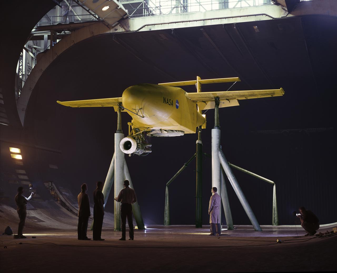
3/4 Low front view of fuselage and fan. Showing jet engine hanging below. Lift fan powered by jet exhaust. General Aerodynamic Characteristics of a Research Model with High Disk Loading Direct Lifting Fan Mounted in Fuselage
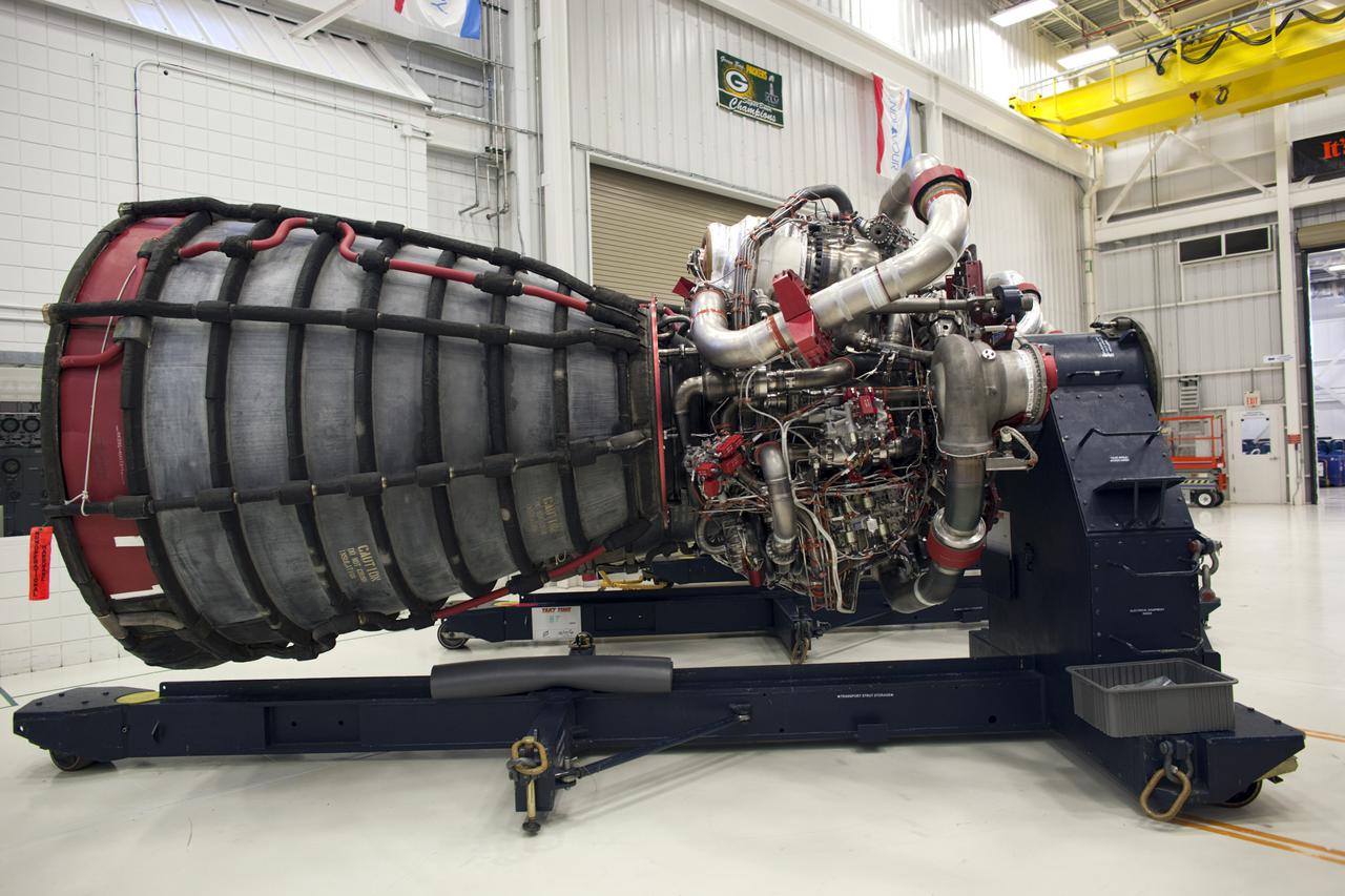
CAPE CANAVERAL, Fla. – Technicians monitor a Pratt and Whitney Rocketdyne space shuttle main engine, or SSME, as a crane lifts it off its base inside the SSME Processing Facility, the engine shop at NASA’s Kennedy Space Center in Florida. Operations are under way to rotate the engine into a horizontal position on a portable workstand. The engine is one of the last SSMEs remaining at Kennedy and is being prepared for shipment to NASA's Stennis Space Center in Mississippi. The first two groups of engines were shipped from Kennedy to Stennis in November 2011 and January 2012 the remaining engines are scheduled to depart on April 9. Altogether, 15 shuttle-era engines will be stored at Stennis for reuse on NASA’s Space Launch System heavy-lift rocket, under development. Photo credit: NASA/Tim Jacobs
KENNEDY SPACE CENTER, FLA. - In the Orbiter Processing Facility, workers lift the liquid oxygen feedline for the 17-inch disconnect toward orbiter Discovery for installation. The 17-inch liquid oxygen and liquid hydrogen disconnects provide the propellant feed interface from the external tank to the orbiter main propulsion system and the three Shuttle main engines.
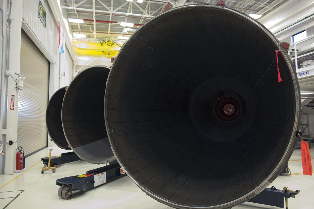
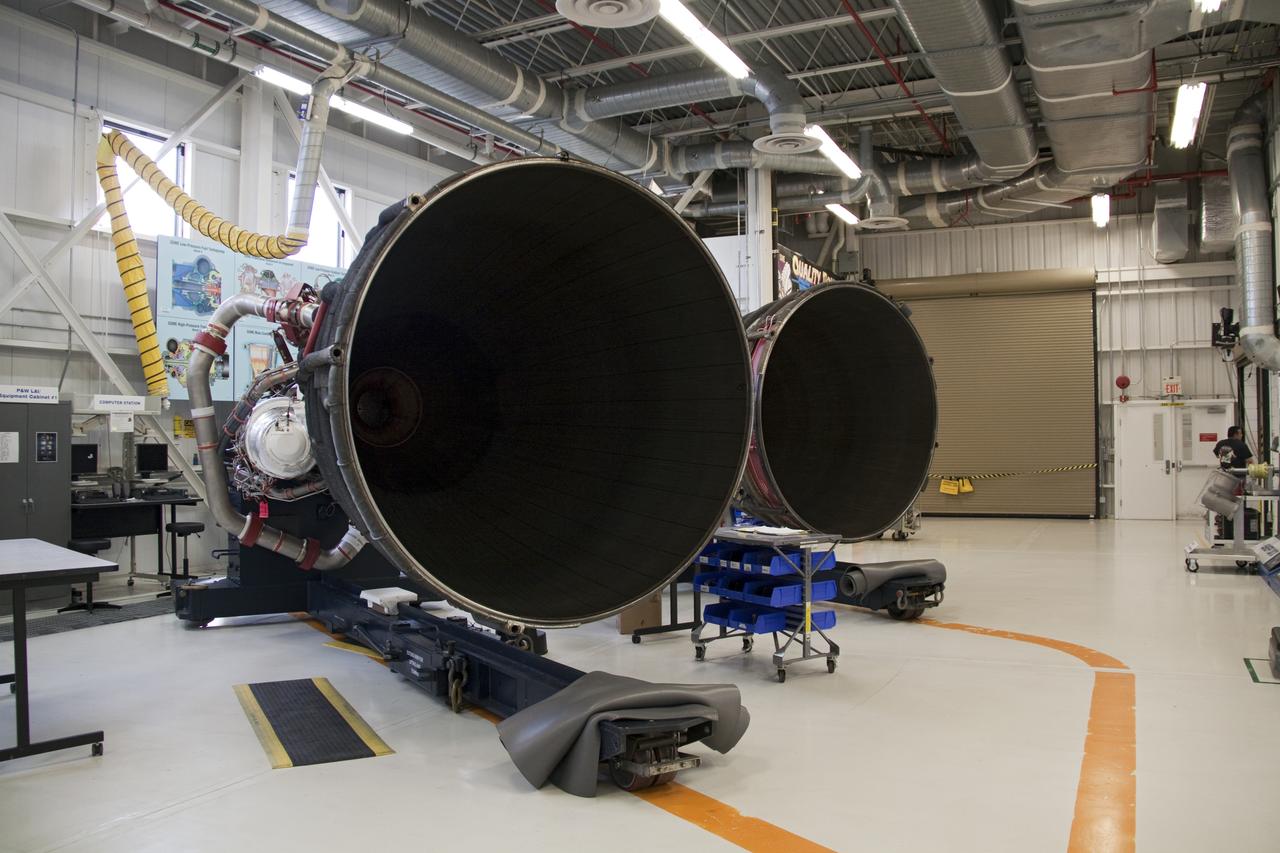
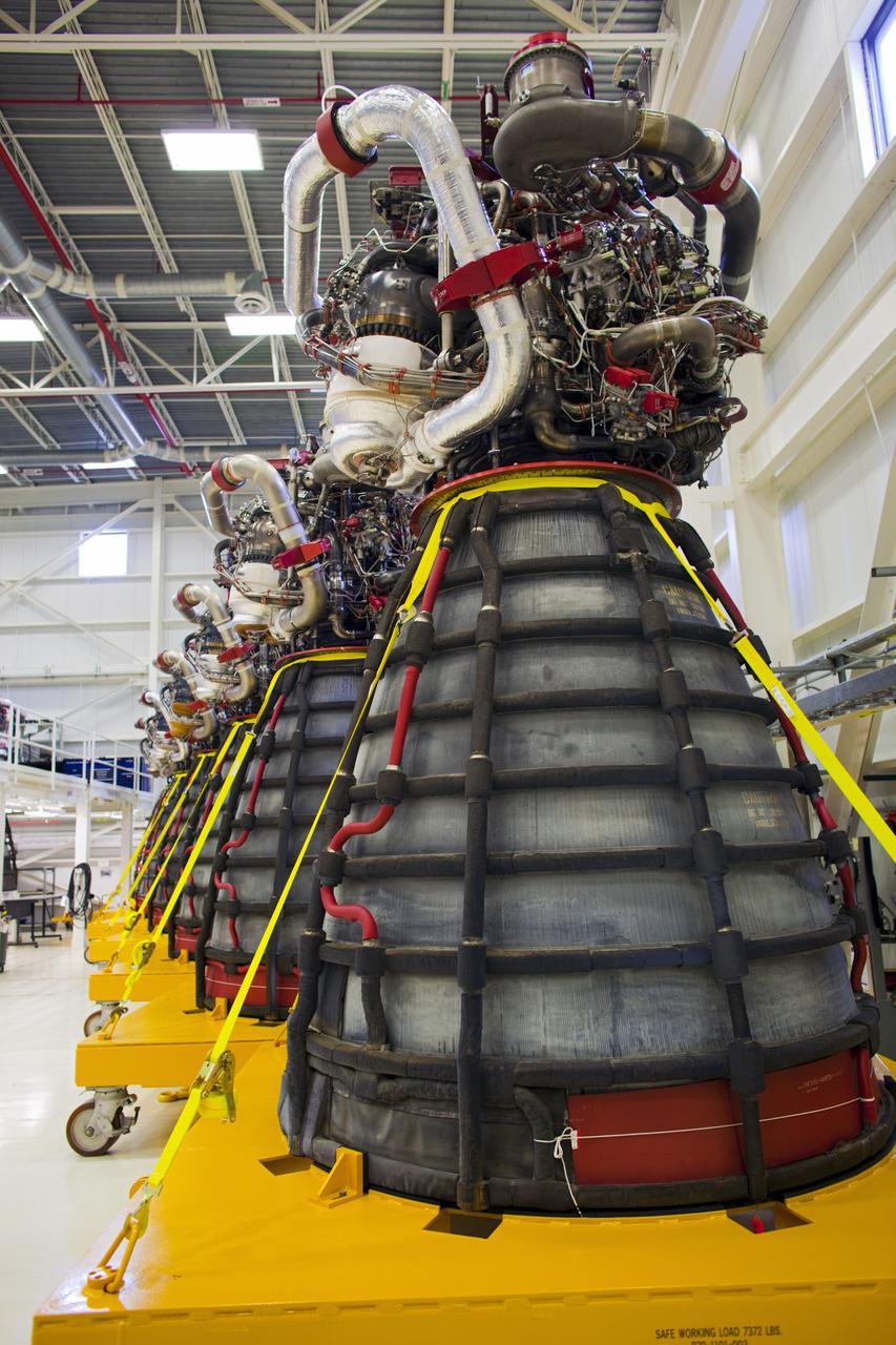
CAPE CANAVERAL, Fla. – At NASA’s Kennedy Space Center in Florida, the large engine bells of several Pratt Whitney Rocketdyne space shuttle main engines (SSMEs) are lined up inside the Engine Shop. For the first time, all 15 main engines are in the Engine Shop at the same time. They are being prepared for shipment to NASA's Stennis Space Center in Mississippi for storage following the completion of the Space Shuttle Program. The engines are being repurposed for use on NASA’s Space Launch System heavy lift rocket. Photo credit: NASA_Dimitri Gerondidakis
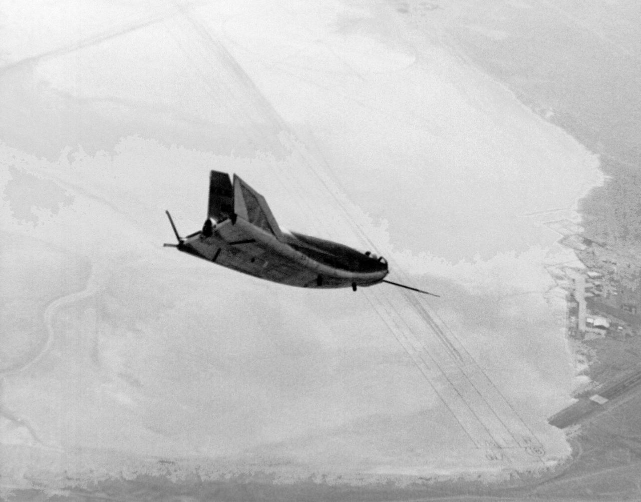
The HL-10 Lifting Body is seen here in flight over Rogers Dry lakebed. Like the other lifting bodies, the HL-10 made a steep descent toward the lakebed, followed by a high-speed landing. This was due to the vehicle's low lift-over-drag ratio. The first 11 flights of the HL-10 were unpowered, flown to check the vehicle's handling and stability before rocket-powered flights began using the XLR-11 rocket engine.
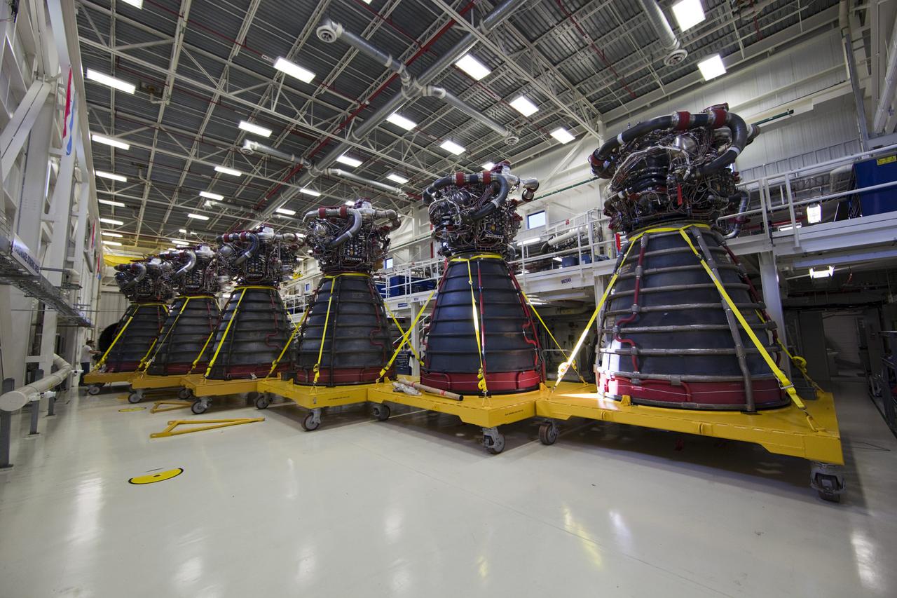
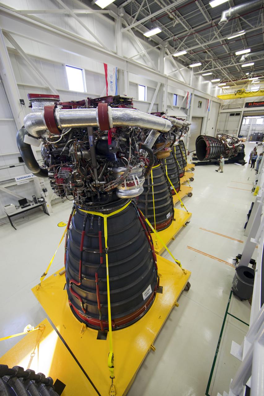
CAPE CANAVERAL, Fla. – Lined up in a row, six Pratt Whitney Rocketdyne space shuttle main engines (SSMEs) sit on stands inside the Engine Shop at NASA’s Kennedy Space Center in Florida. For the first time, all 15 main engines are in the Engine Shop at the same time. They are being prepared for shipment to NASA's Stennis Space Center in Mississippi for storage following the completion of the Space Shuttle Program. The engines are being repurposed for use on NASA’s Space Launch System heavy lift rocket. Photo credit: NASA_Dimitri Gerondidakis
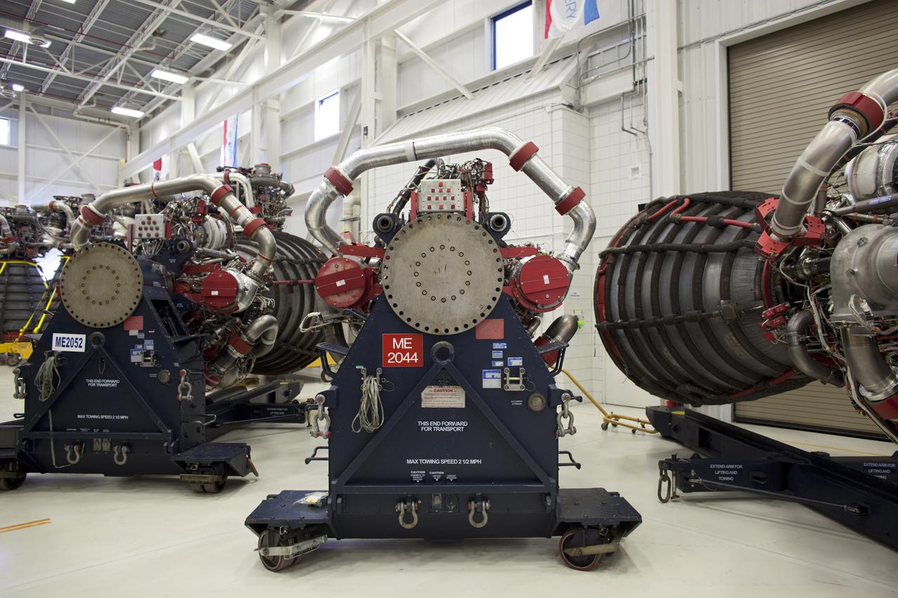
CAPE CANAVERAL, Fla. – Several Pratt Whitney Rocketdyne space shuttle main engines (SSMEs) sit on stands inside the Engine Shop at NASA’s Kennedy Space Center in Florida. For the first time, all 15 main engines are in the Engine Shop at the same time. They are being prepared for shipment to NASA's Stennis Space Center in Mississippi for storage following the completion of the Space Shuttle Program. The engines are being repurposed for use on NASA’s Space Launch System heavy lift rocket. Photo credit: NASA_Dimitri Gerondidakis
CAPE CANAVERAL, Fla. – At NASA’s Kennedy Space Center in Florida, a Pratt Whitney Rocketdyne space shuttle main engine (SSME) sits on a stand inside the Engine Shop. For the first time, all 15 main engines are in the Engine Shop at the same time. They are being prepared for shipment to NASA's Stennis Space Center in Mississippi for storage following the completion of the Space Shuttle Program. The engines are being repurposed for use on NASA’s Space Launch System heavy lift rocket. Photo credit: NASA_Dimitri Gerondidakis
CAPE CANAVERAL, Fla. – Lined up in a row, several Pratt Whitney Rocketdyne space shuttle main engines (SSMEs) sit on stands inside the Engine Shop at NASA’s Kennedy Space Center in Florida. For the first time, all 15 main engines are in the Engine Shop at the same time. They are being prepared for shipment to NASA's Stennis Space Center in Mississippi for storage following the completion of the Space Shuttle Program. The engines are being repurposed for use on NASA’s Space Launch System heavy lift rocket. Photo credit: NASA_Dimitri Gerondidakis
CAPE CANAVERAL, Fla. – Lined up in a row, six Pratt Whitney Rocketdyne space shuttle main engines (SSMEs) sit on stands inside the Engine Shop at NASA’s Kennedy Space Center in Florida. For the first time, all 15 main engines are in the Engine Shop at the same time. They are being prepared for shipment to NASA's Stennis Space Center in Mississippi for storage following the completion of the Space Shuttle Program. The engines are being repurposed for use on NASA’s Space Launch System heavy lift rocket. Photo credit: NASA_Dimitri Gerondidakis
The engine vertical installer for NASA’s Space Launch System (SLS) is inside the Vehicle Assembly at NASA’s Kennedy Space Center in Florida on April 25, 2019. The engine installer will be lifted up by crane for transfer to High Bay 3. The engine installer arrived from the manufacturer, Precision Fabrication and Cleaning in Canaveral Groves, Florida. The new ground support equipment will be ready for preflight processing in the event one of the four RS-25 engines on the core stage of the SLS rocket needs to be replaced. During launch of the SLS and Orion spacecraft, the four core stage engines will provide the thrust needed to lift the rocket and Orion spacecraft off Launch Pad 39B at Kennedy for Exploration Mission-1. The uncrewed Orion will travel on a three-week test mission thousands of miles beyond the Moon and back to Earth for a splashdown in the Pacific Ocean.
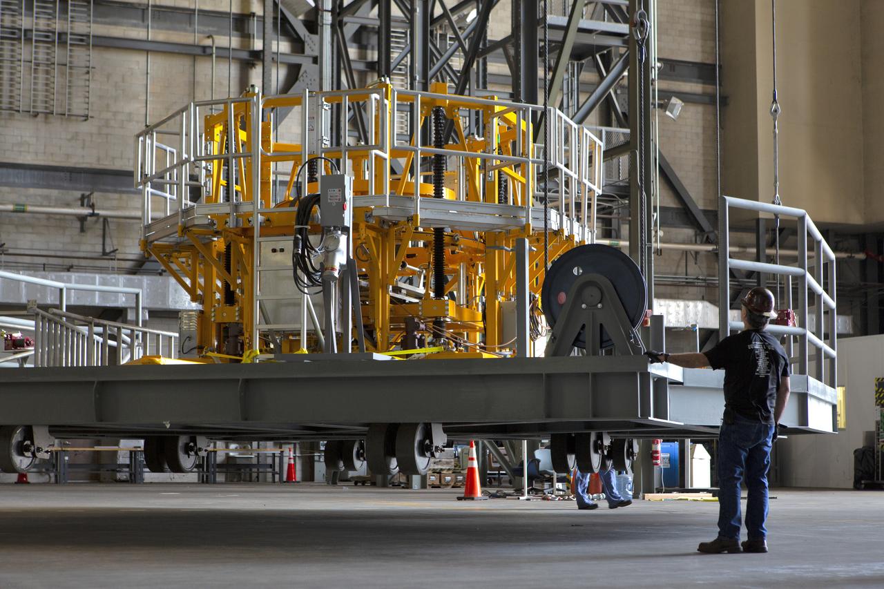
The engine vertical installer for NASA’s Space Launch System (SLS) is inside the Vehicle Assembly at NASA’s Kennedy Space Center in Florida on April 25, 2019. The engine installer is being lifted up by crane for transfer to High Bay 3. The engine installer arrived from the manufacturer, Precision Fabrication and Cleaning in Canaveral Groves, Florida. The new ground support equipment will be ready for preflight processing in the event one of the four RS-25 engines on the core stage of the SLS rocket needs to be replaced. During launch of the SLS and Orion spacecraft, the four core stage engines will provide the thrust needed to lift the rocket and Orion spacecraft off Launch Pad 39B at Kennedy for Exploration Mission-1. The uncrewed Orion will travel on a three-week test mission thousands of miles beyond the Moon and back to Earth for a splashdown in the Pacific Ocean.
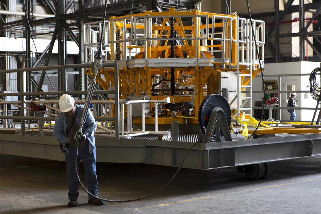
The engine vertical installer for NASA’s Space Launch System (SLS) is inside the Vehicle Assembly at NASA’s Kennedy Space Center in Florida on April 25, 2019. Preparations are underway to lift the engine installer up and into High Bay 3. The engine installer arrived from the manufacturer, Precision Fabrication and Cleaning in Canaveral Groves, Florida. The new ground support equipment will be ready for preflight processing in the event one of the four RS-25 engines on the core stage of the SLS rocket needs to be replaced. During launch of the SLS and Orion spacecraft, the four core stage engines will provide the thrust needed to lift the rocket and Orion spacecraft off Launch Pad 39B at Kennedy for Exploration Mission-1. The uncrewed Orion will travel on a three-week test mission thousands of miles beyond the Moon and back to Earth for a splashdown in the Pacific Ocean.
The engine vertical installer for NASA’s Space Launch System (SLS) is inside the Vehicle Assembly at NASA’s Kennedy Space Center in Florida on April 25, 2019. The engine installer is being lifted up by crane for transfer to High Bay 3. The engine installer arrived from the manufacturer, Precision Fabrication and Cleaning in Canaveral Groves, Florida. The new ground support equipment will be ready for preflight processing in the event one of the four RS-25 engines on the core stage of the SLS rocket needs to be replaced. During launch of the SLS and Orion spacecraft, the four core stage engines will provide the thrust needed to lift the rocket and Orion spacecraft off Launch Pad 39B at Kennedy for Exploration Mission-1. The uncrewed Orion will travel on a three-week test mission thousands of miles beyond the Moon and back to Earth for a splashdown in the Pacific Ocean.
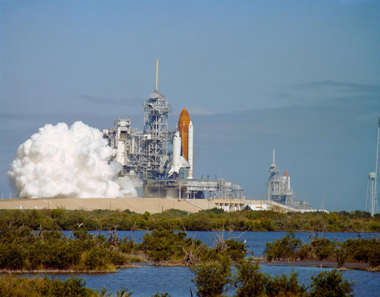
S93-31601 (March 1993) --- The second Space Shuttle launch attempt of 1993 comes to an abrupt halt when one of the three main engines on the orbiter Columbia shuts down at T -3 seconds, resulting in an on-the-pad abort of Mission STS-55. This was the first time in the post-Challenger era that a main engine shutdown has halted a Shuttle launch countdown, and only the third time in the history of the program. In 1984, STS-41D was scrubbed at T -4 seconds when the orbiter General Purpose Computer detected an anomaly in a main engine, and in 1985, STS-51F was halted at T -3 seconds due to a main engine malfunction that caused shutdown of all three engines. Columbia had been scheduled to lift off from Launch Pad 39B is the Space Shuttle Discovery, undergoing preparations for lift off on Mission STS-56.
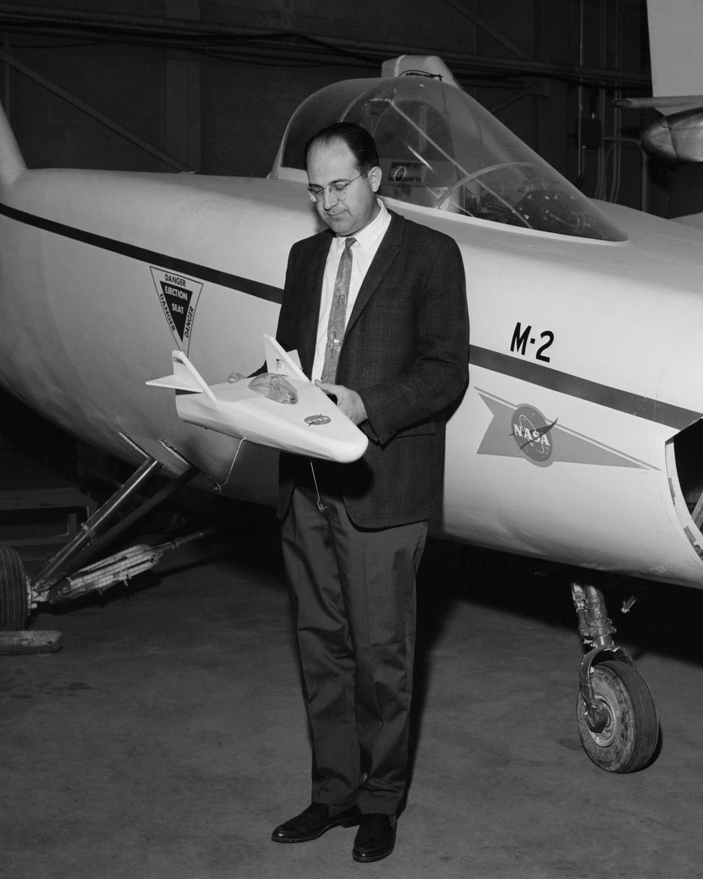
Dale Reed with a model of the M2-F1 in front of the actual lifting body. Reed used the model to show the potential of the lifting bodies. He first flew it into tall grass to test stability and trim, then hand-launched it from buildings for longer flights. Finally, he towed the lifting-body model aloft using a powered model airplane known as the "Mothership." A timer released the model and it glided to a landing. Dale's wife Donna used a 9 mm. camera to film the flights of the model. Its stability as it glided--despite its lack of wings--convinced Milt Thompson and some Flight Research Center engineers including the center director, Paul Bikle, that a piloted lifting body was possible.
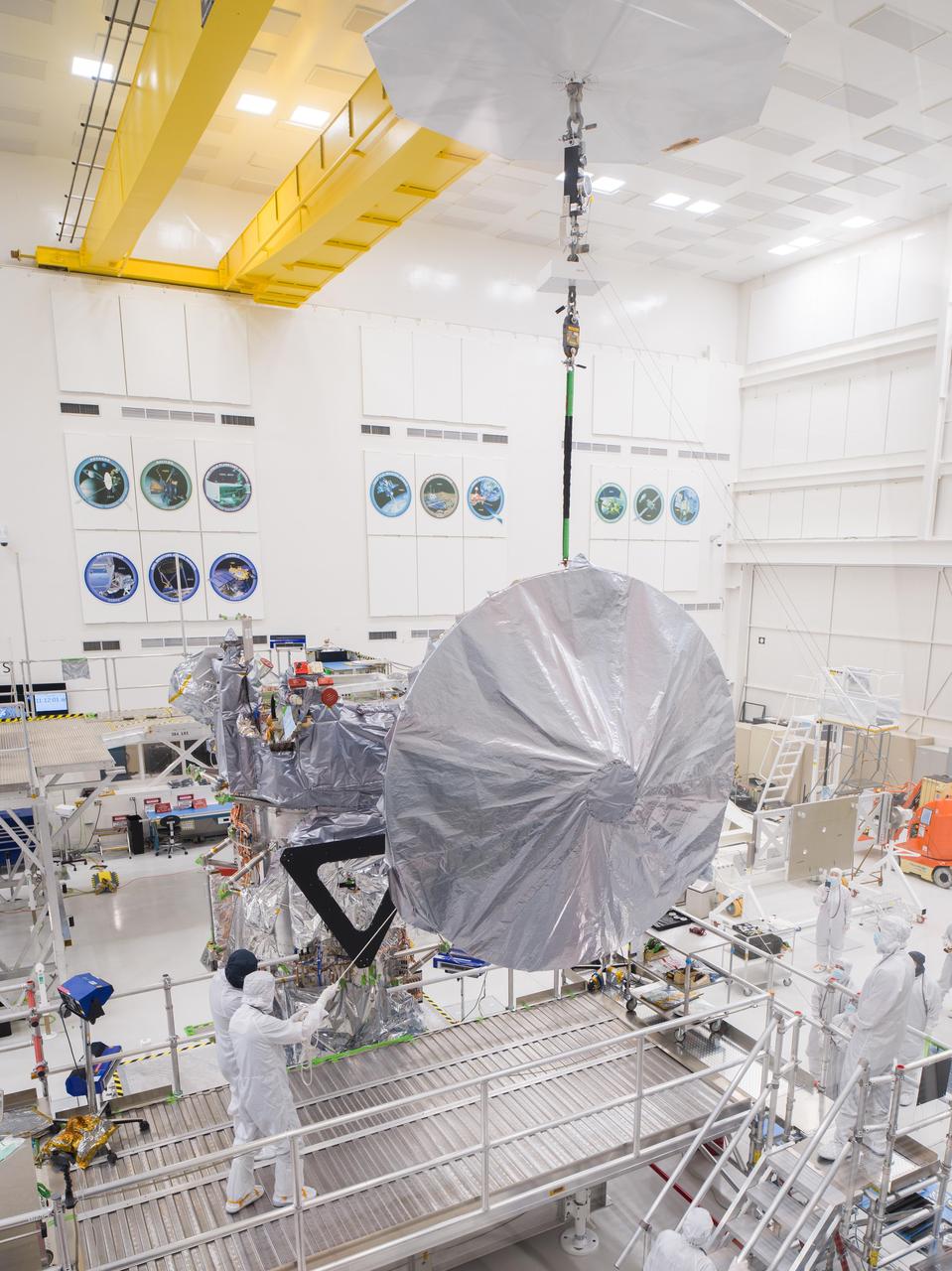
Engineers and technicians use a crane to lift a 10-foot (3-meter) high-gain antenna as they prepare to install it on NASA's Europa Clipper spacecraft on Aug. 14, 2023. The orbiter is being assembled in the clean room of High Bay 1 at the agency's Jet Propulsion Laboratory in Southern California in preparation for its launch to Jupiter's moon Europa in October 2024. The precision-engineered dish was attached to the spacecraft in carefully choreographed stages over the course of several hours. Europa Clipper will need the huge antenna to transmit data hundreds of millions of miles back to Earth. Scientists believe the icy moon Europa harbors a vast internal ocean that may have conditions suitable for supporting life. The spacecraft will fly by the moon about 50 times while its science instruments gather data on the moon's atmosphere, surface, and interior – information that will help scientists learn more about the ocean, the ice crust, and potential plumes that may be venting subsurface water into space. https://photojournal.jpl.nasa.gov/catalog/PIA25956
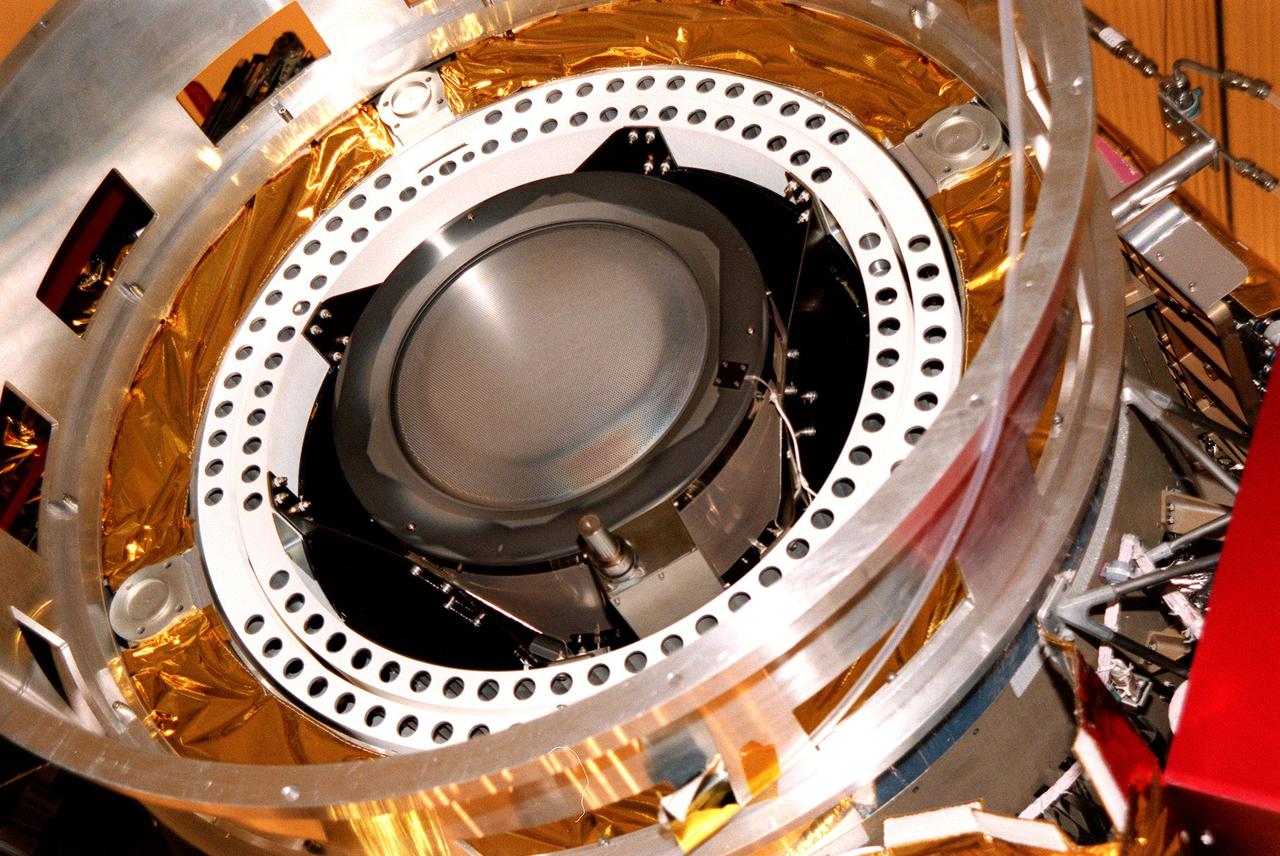
Kennedy Space Center, Florida. - Deep Space 1 is lifted from its work platform, giving a closeup view of the experimental solar-powered ion propulsion engine. The ion propulsion engine is the first non-chemical propulsion to be used as the primary means of propelling a spacecraft. The first flight in NASA's New Millennium Program, Deep Space 1 is designed to validate 12 new technologies for scientific space missions of the next century. Another onboard experiment includes software that tracks celestial bodies so the spacecraft can make its own navigation decisions without the intervention of ground controllers. Deep Space 1 will complete most of its mission objectives within the first two months, but may also do a flyby of a near-Earth asteroid, 1992 KD, in July 1999. Deep Space 1 will be launched aboard a Boeing Delta 7326 rocket from Launch Pad 17A, Cape Canaveral Air Station, in October. Delta II rockets are medium capacity expendable launch vehicles derived from the Delta family of rockets built and launched since 1960. Since then there have been more than 245 Delta launches. http://photojournal.jpl.nasa.gov/catalog/PIA04232
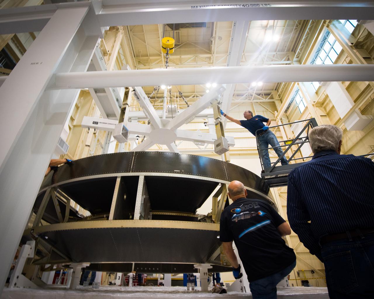
Engineers lift the Orion Crew Module Adapter Structural Test Article into the test stand at NASA Glenn Research Center Plum Brook Facility on Sept. 23, 2015. Part of Batch image transfer from Flickr.
The new production nozzle is lifted on the Fred Haise Test Stand at NASA’s Stennis Space Center on Feb. 6. Crews used specially adapted procedures and tools to swap out the nozzles with the engine in place.
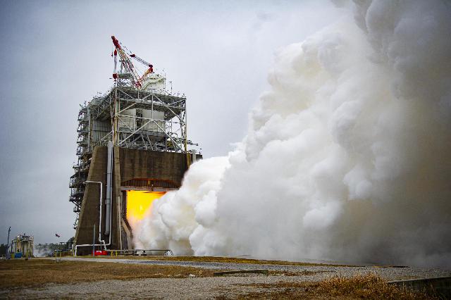
Crews exceed the 111% power level needed to lift the SLS (Space Launch System) rocket when firing the RS-25 certification engine at 113% on Jan. 23 at NASA’s Stennis Space Center.
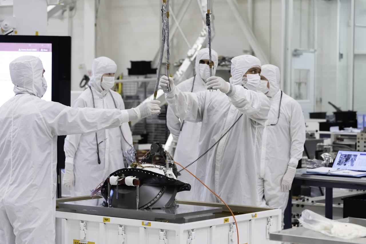
Engineers and technicians from the Global Ecosystem Dynamics Investigation (GEDI) use a crane to lift the Optical Bench during integration activities inside the Spacecraft Checkout and Integraton Area (SCA) clean room at Goddard Space Flight Center
Engineers lift the Orion Crew Module Adapter Structural Test Article into the test stand at NASA Glenn Research Center Plum Brook Facility on Sept. 23, 2015. Part of Batch image transfer from Flickr.
Engineers lift the Orion Crew Module Adapter Structural Test Article into the test stand at NASA Glenn Research Center Plum Brook Facility on Sept. 23, 2015. Part of Batch image transfer from Flickr.
Engineers lift the Orion Crew Module Adapter Structural Test Article into the test stand at NASA Glenn Research Center Plum Brook Facility on Sept. 23, 2015. Part of Batch image transfer from Flickr.
Engineers lift the Orion Crew Module Adapter Structural Test Article into the test stand at NASA Glenn Research Center Plum Brook Facility on Sept. 23, 2015. Part of Batch image transfer from Flickr.
A team of engineers lifts the mast into place atop of NASA’s VIPER robotic Moon rover in a clean room at NASA’s Johnson Space Center in Houston. Credit: NASA/Helen Arase Vargas
Engineers lift the Orion Crew Module Adapter Structural Test Article into the test stand at NASA Glenn Research Center Plum Brook Facility on Sept. 23, 2015. Part of Batch image transfer from Flickr.
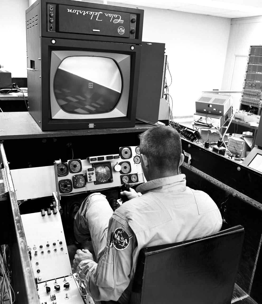
As shown in this photo of the HL-10 flight simulator, the lifting-body pilots and engineers made use of early simulators for both training and the determination of a given vehicle's handling at various speeds, attitudes, and altitudes. This provided warning of possible problems.
3/4 lower front view of DC-9 lift/cruz fan transport model. Pictured with Eloy Martinez (left, mechanic) Leo Hall (right, engineer).
Engineers lift the Orion Crew Module Adapter Structural Test Article into the test stand at NASA Glenn Research Center Plum Brook Facility on Sept. 23, 2015. Part of Batch image transfer from Flickr.
Engineers lift the Orion Crew Module Adapter Structural Test Article into the test stand at NASA Glenn Research Center Plum Brook Facility on Sept. 23, 2015. Part of Batch image transfer from Flickr.
VANDENBERG AFB, California – Technicians and engineers begin lifting NASA's SMAP spacecraft to the top of a Delta II rocket at Space Launch Complex-2 for launch. For more, go to www.nasa.gov/smap Photo credit: USAF
Engineers and technicians at the Marshall Space Flight Center were installing an F-I engine on the Saturn V S-IC (first) stage thrust structure in building 4705. The S-IC (first) stage used five F-1 engines that produced a total thrust of 7,500,000 pounds as each engine produced 1,500,000 pounds of thrust. The S-IC stage lifted the Saturn V vehicle and Apollo spacecraft from the launch pad.
KENNEDY SPACE CENTER, FLA. - Inside the KSC Engine Shop, the third Space Shuttle Main Engine for Discovery’s Return to Flight mission STS-114 is ready to be lifted off the trailer. The engine is returning from NASA’s Stennis Space Center in Mississippi where it underwent a hot fire acceptance test. Typically, the engines are installed on an orbiter in the Orbiter Processing Facility approximately five months before launch.

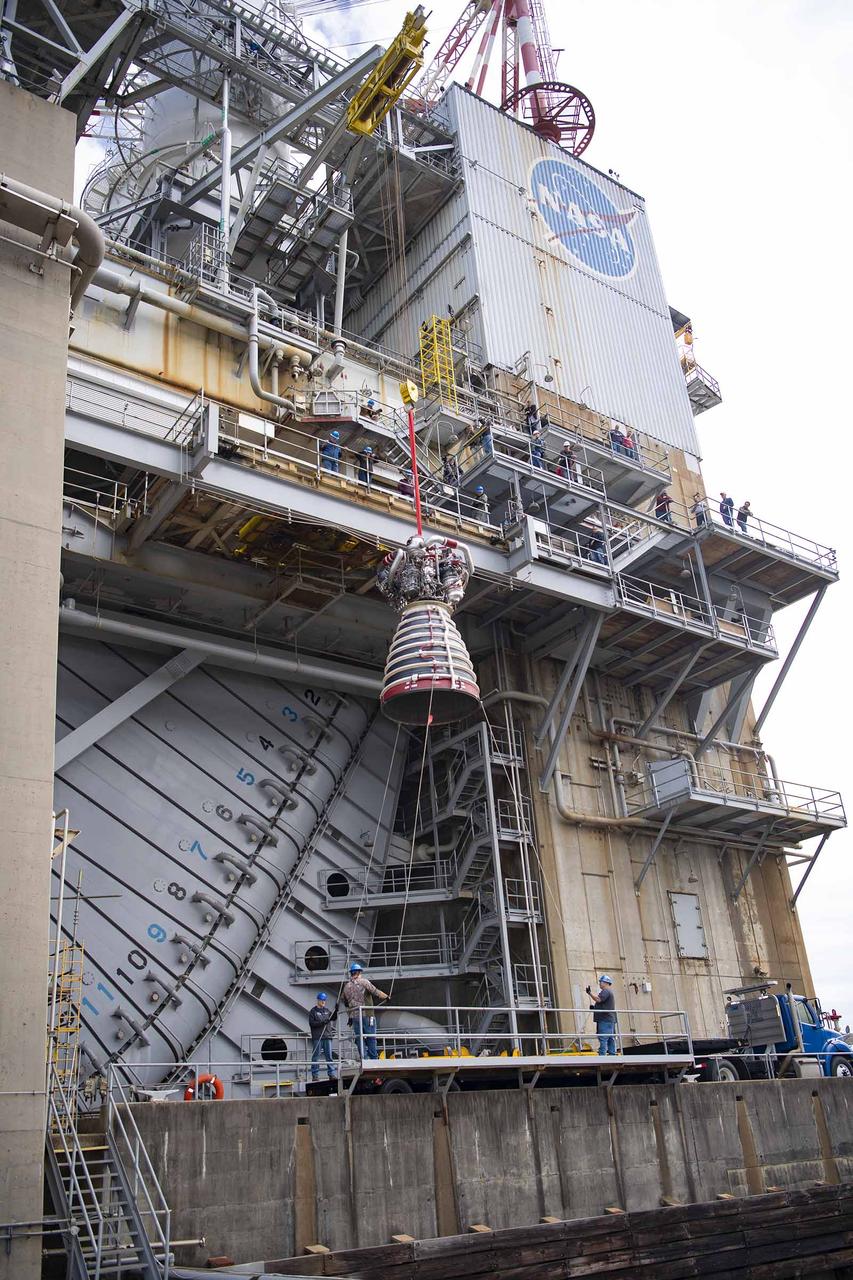
The first RS-25 flight engine, engine No. 2059, is lifted onto the A-1 Test Stand at Stennis Space Center on Nov. 4, 2015. The engine was tested in early 2016 to certify it for use on NASA’s new Space Launch System (SLS). The SLS core stage will be powered by four RS-25 engines, all tested at Stennis Space Center. NASA is developing the SLS to carry humans deeper into space than ever before, including on a journey to Mars.
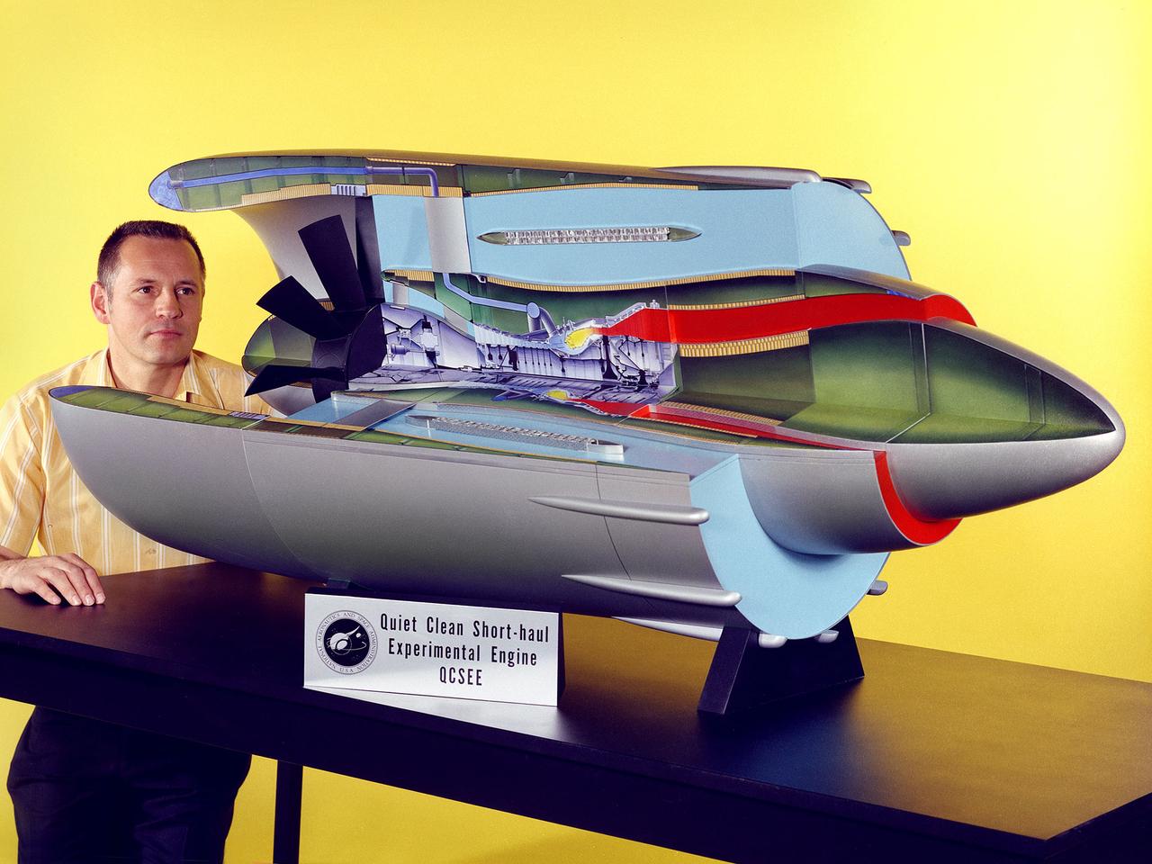
Program manager Carl Ciepluch poses with a model of the Quiet Clean Short Haul Experimental Engine (QCSEE) conceived by the National Aeronautics and Space Administration (NASA) Lewis Research Center. The QCSEE engine was designed to power future short-distance transport aircraft without generating significant levels of noise or pollution and without hindering performance. The engines were designed to be utilized on aircraft operating from small airports with short runways. Lewis researchers investigated two powered-lift designs and an array of new technologies to deal with the shorter runways. Lewis contracted General Electric to design the two QCSEE engines—one with over-the-wing power-lift and one with an under-the-wing design. A scale model of the over-the-wing engine was tested in the Full Scale Tunnel at the Langley Research Center in 1975 and 1976. Lewis researchers investigated both versions in a specially-designed test stand, the Engine Noise Test Facility, on the hangar apron. The QCSEE engines met the goals set out by the NASA researchers. The aircraft industry, however, never built the short-distance transport aircraft for which the engines were intended. Different technological elements of the engine, however, were applied to some future General Electric engines.
KENNEDY SPACE CENTER, FLA. - In the Space Shuttle Main Engine (SSME) Shop, the SSME is lifted and moved toward the Hyster lift that will transport it to the Orbiter Processing Facility. There it will be installed in the orbiter Discovery for Return to Flight mission STS-114. This is the third SSME to be installed in Discovery. Overall, an SSME weighs approximately 7,000 pounds. An SSME operates at greater temperature extremes than any mechanical system in common use today. The liquid hydrogen fuel is -423 degrees Fahrenheit, the second coldest liquid on Earth. When the hydrogen is burned with liquid oxygen, the temperature in the engine's combustion chamber reaches +6000 degrees Fahrenheit -- higher than the boiling point of iron. Each SSME is controlled by its own computer, which checks the health of the engines 50 times per second during countdown and ascent. The controller can shut an engine down if it detects a problem.
The engine vertical installer for NASA’s Space Launch System (SLS) is being lifted by crane in the Vehicle Assembly Building at NASA’s Kennedy Space Center in Florida on April 25, 2019. The engine installer arrived from the manufacturer, Precision Fabrication and Cleaning in Canaveral Groves, Florida. The new ground support equipment will be transferred into High Bay 3 where it will be ready for preflight processing in the event one of the four RS-25 engines on the core stage of the SLS rocket needs to be replaced. During launch of the SLS and Orion spacecraft, the four core stage engines will provide the thrust needed to lift the rocket and Orion spacecraft off Launch Pad 39B at Kennedy for Exploration Mission-1. The uncrewed Orion will travel on a three-week test mission thousands of miles beyond the Moon and back to Earth for a splashdown in the Pacific Ocean.
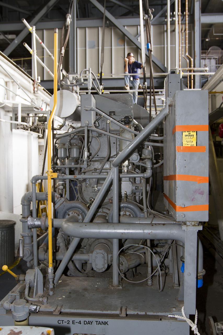
CAPE CANAVERAL, Fla. ––Inside the Vehicle Assembly Building at NASA’s Kennedy Space Center in Florida, a technician monitors the progress as a crane begins to lift an Apollo era diesel engine from crawler-transporter 2 CT-2). New engines will be installed later this month. Work is in progress in high bay 2 to upgrade CT-2 so that it can carry NASA’s Space Launch System heavy-lift rocket, which is under design, and new Orion spacecraft to the launch pad. The crawler-transporters were used to carry the mobile launcher platform and space shuttle to Launch Complex 39 for space shuttle launches for 30 years. Photo credit: NASA/Kim Shiflett