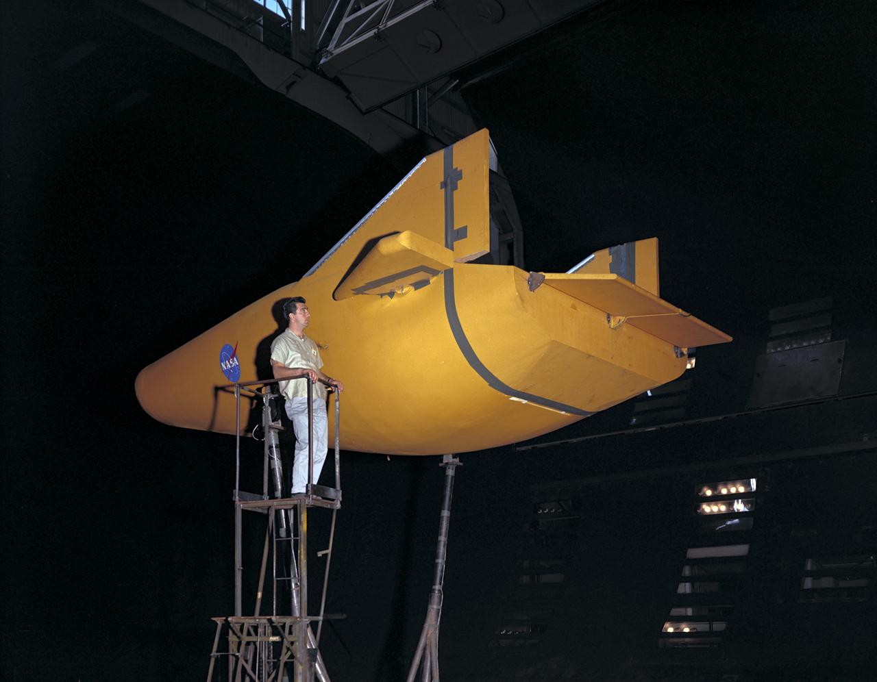
M-2 lifting body wind tunnel model with wind tunnel mechanic Chuck Greco. Model mounted on special support designed for lifting body models. Flaps and elevons visible.
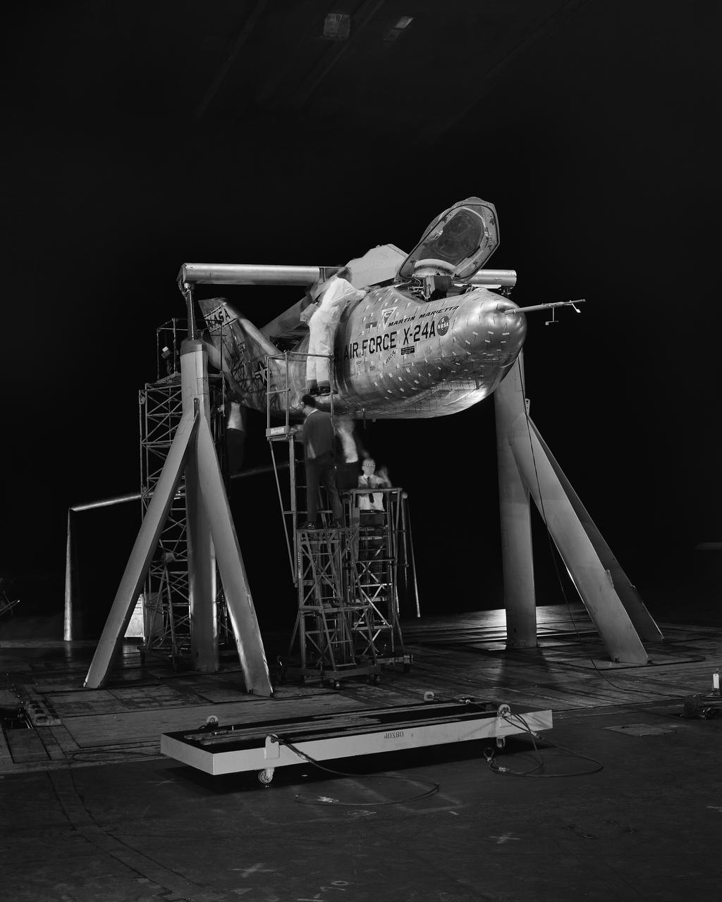
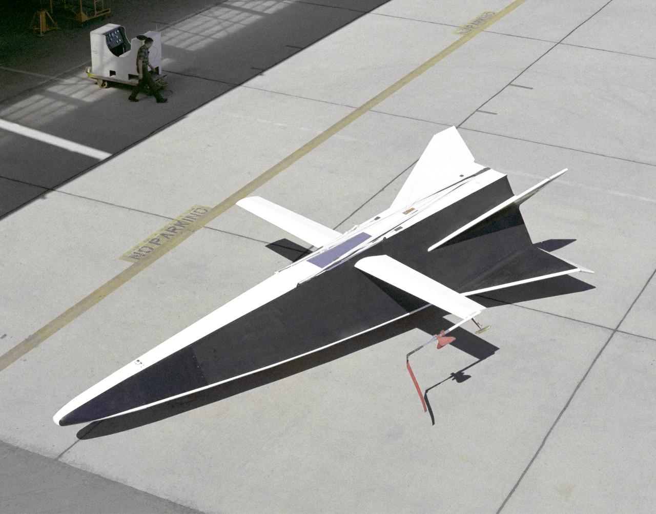
3/4 front view of Martin X-24A lifting body, mounted on B-52 mount.
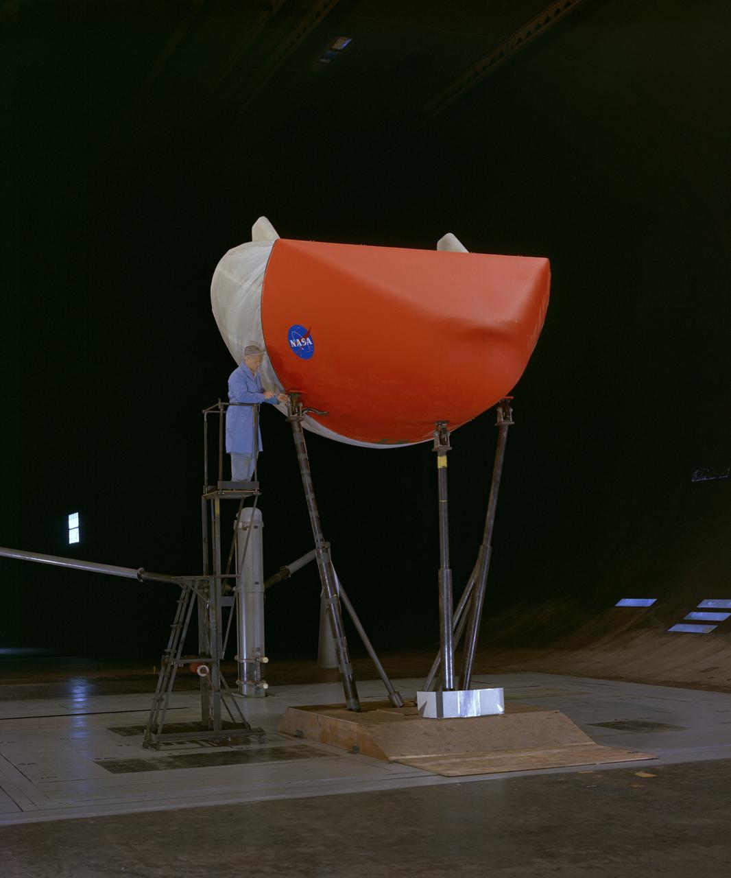
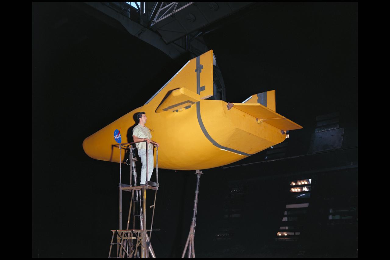
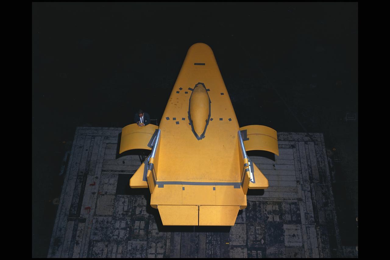
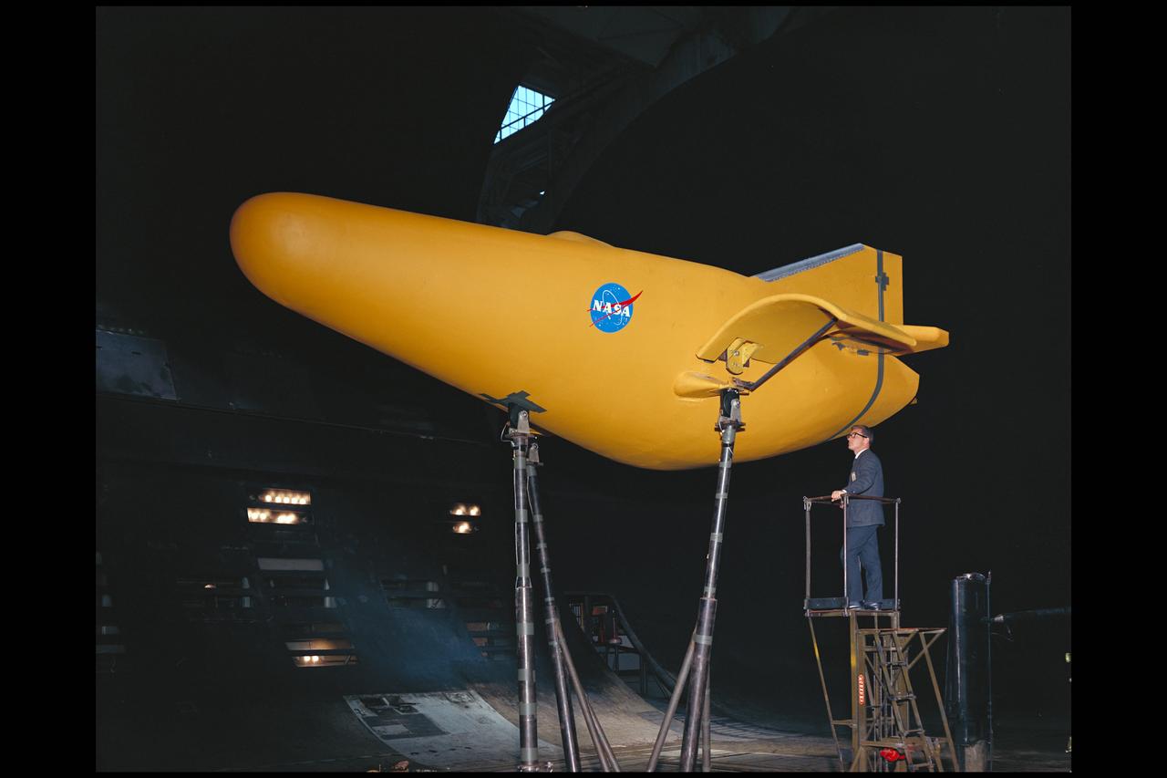
3/4 front view of M-1-L inflatable recovery able lifting body model in Ames 40x80 foot wind tunnel. Mechanic, Ray Schmorance included in picture.
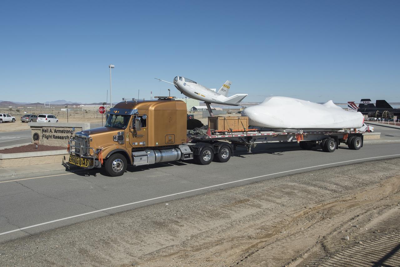
SNC delivers Dream Chaser to NASA Armstrong posing it with the HL-10 lifting body flown the 1960s.
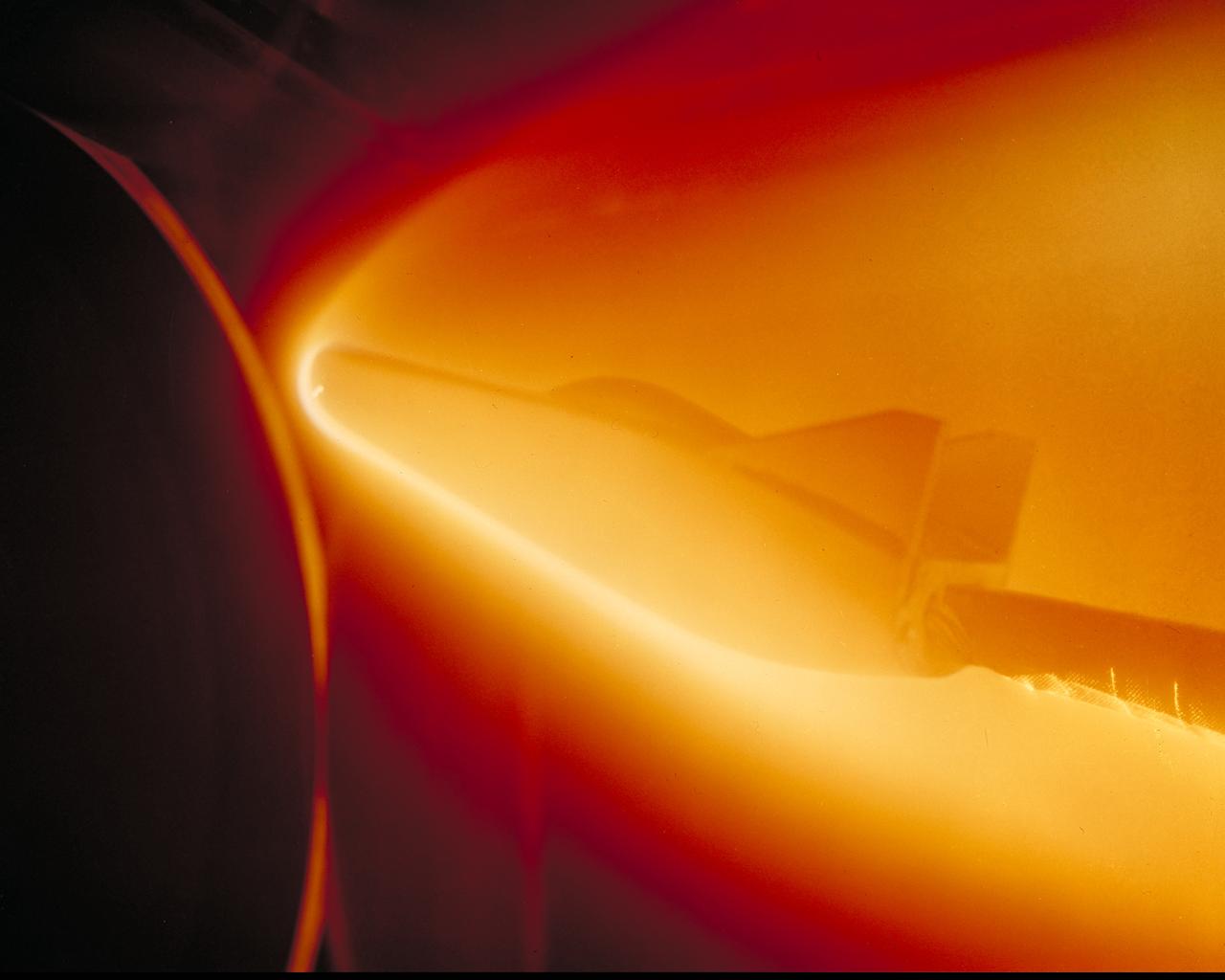
M-2 Lifting Body being tested in Ames atmospheric entry simulator to determine the areas of most intense heat.
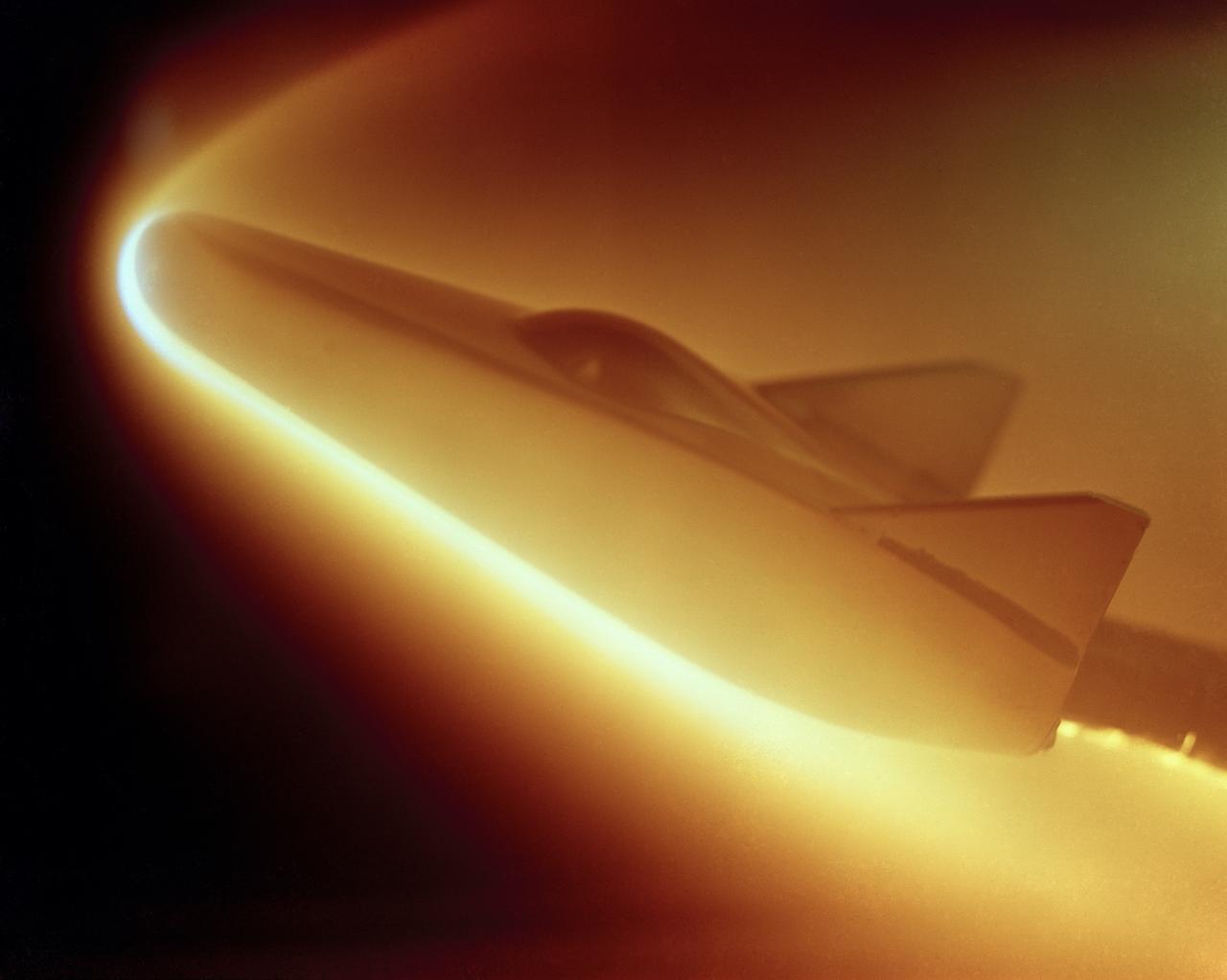
M-2 lifting body; heat transfer distribution test in the 1 ft hypervelocity wind tunnel
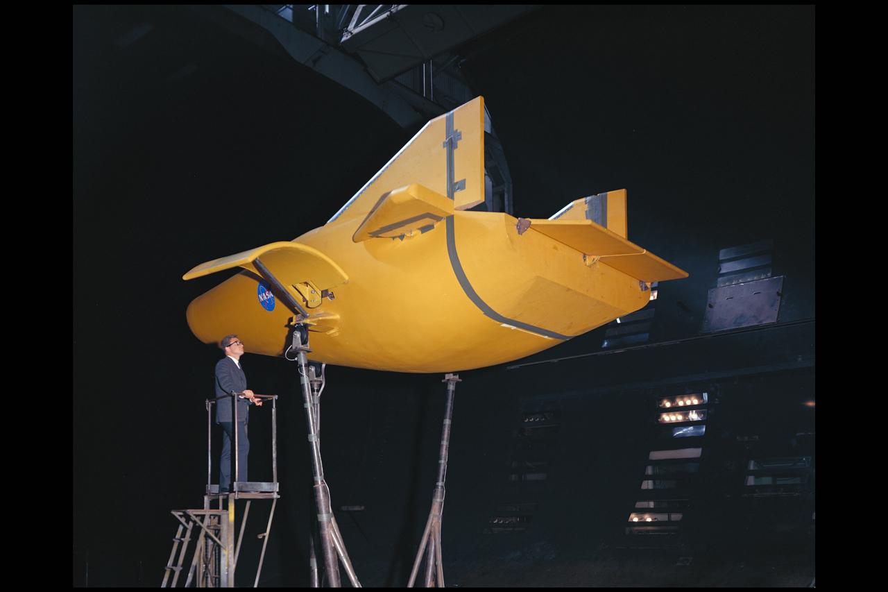
M-2 Lifting body 40x80ft Full Scale Wind Tunnle
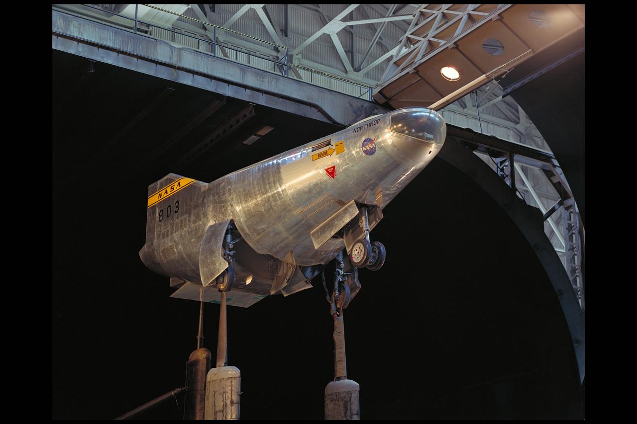
M2-F2 lifting body flight vehicle in 40x80ft w.t.
M-2 Lifting body 40x80ft Full Scale Wind Tunnle
M-2 Lifting body 40x80ft Full Scale Wind Tunnle
M-2 Lifting body 40x80ft Full Scale Wind Tunnel
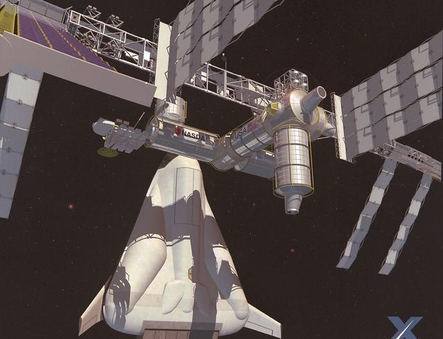
Pictured here is an artist's depiction of Lockheed Martin's Lifting Body Single-Stage-to-Orbit (SSTO) Reusable Launch Vehicle (RLV) concept servicing the International Space Station. The development of the RLV is essential in the cost reduction of future space travel.
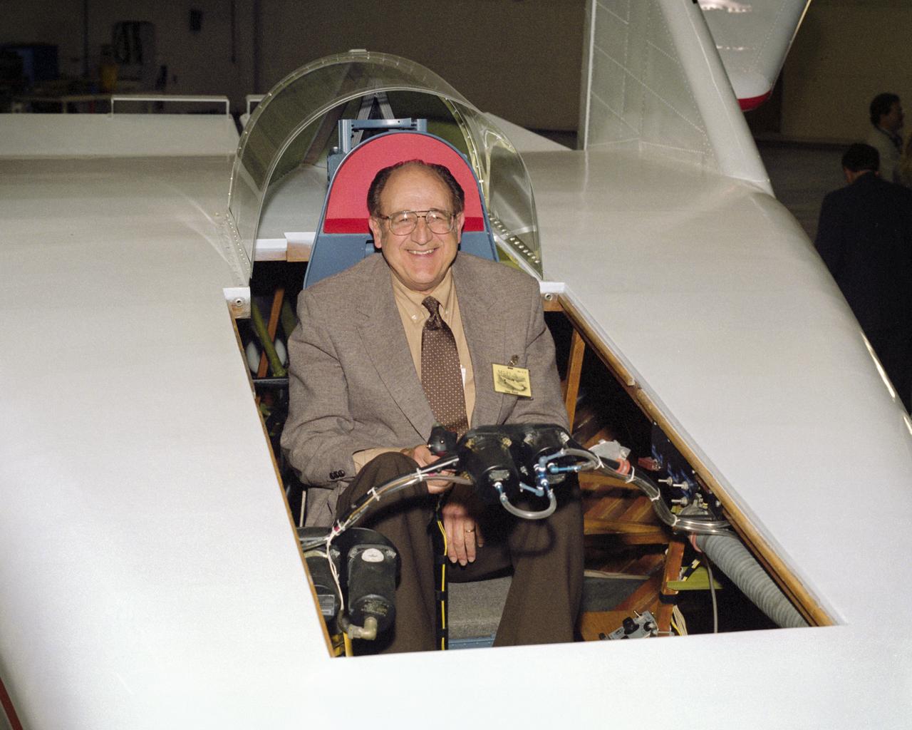
Often called the "Father of the Lifting Bodies," NASA aerospace engineer Dale Reed enjoys a moment in the cockpit of the restored wingless M2-F1 in 1997.
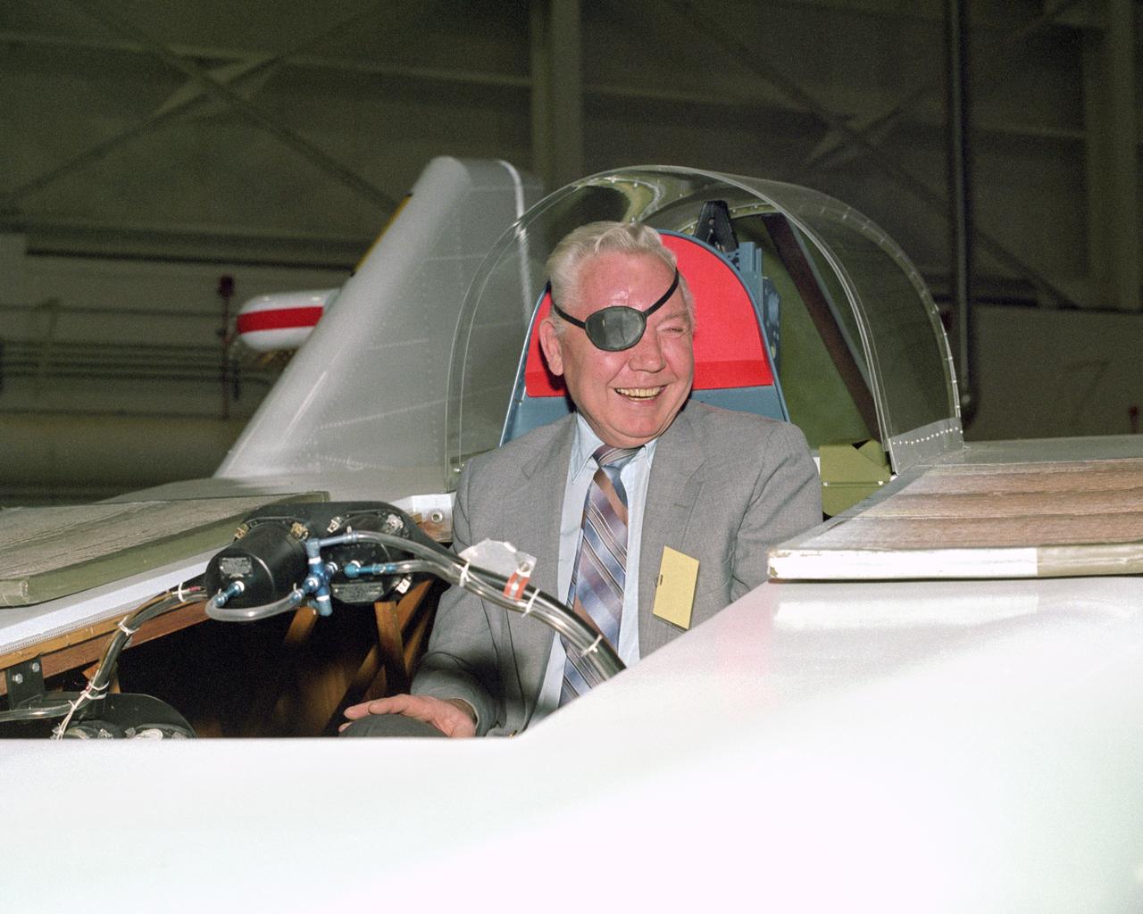
NASA Pilot Bruce Peterson in the cockpit of the restored M2-F1 Lifting Body.
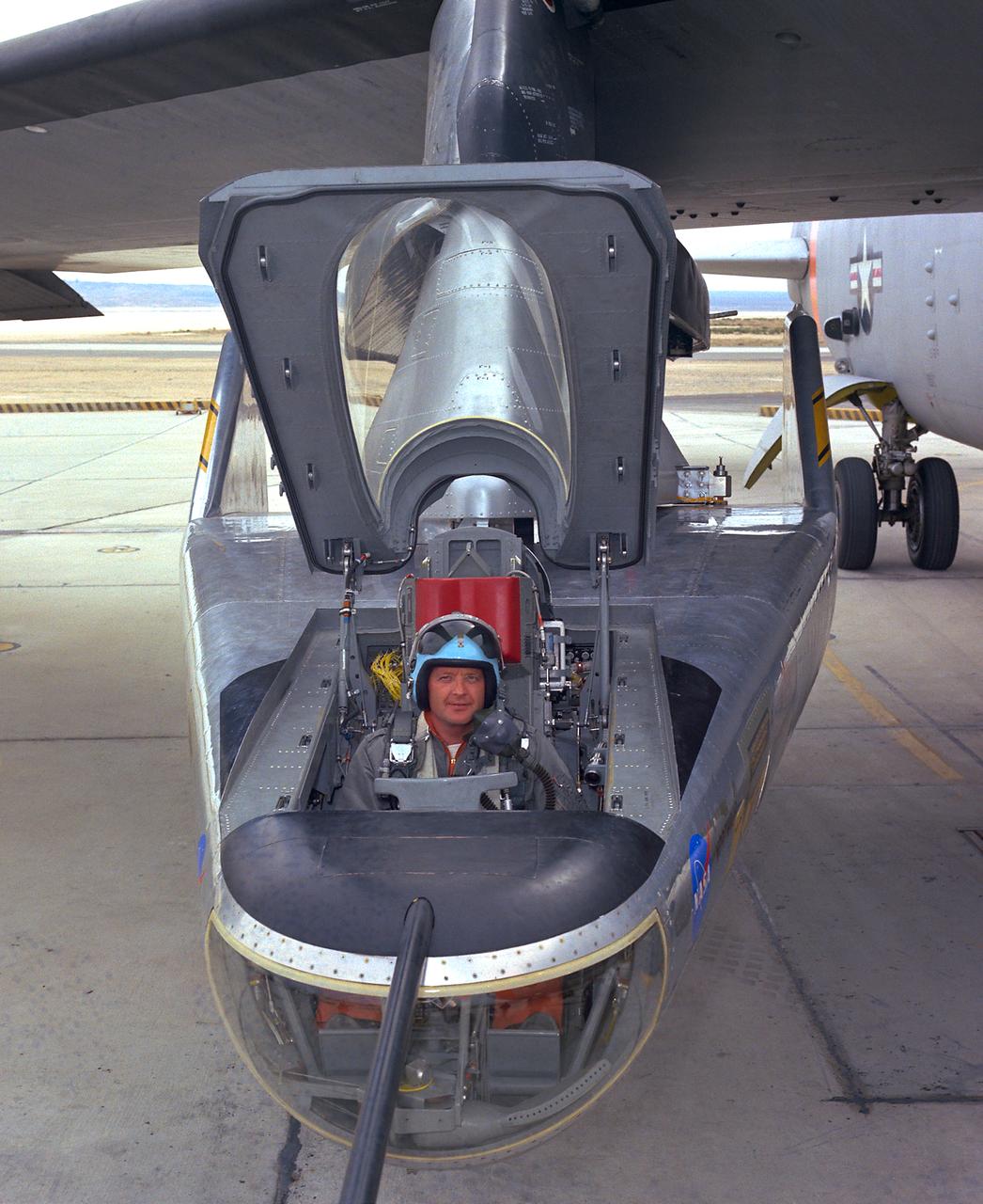
NASA research pilot Milt Thompson sits in the M2-F2 "heavyweight" lifting body research vehicle before a 1966 test flight. The M2-F2 and the other lifting-body designs were all attached to a wing pylon on NASA’s B-52 mothership and carried aloft. The vehicles were then drop-launched and, at the end of their flights, glided back to wheeled landings on the dry lake or runway at Edwards AFB. The lifting body designs influenced the design of the Space Shuttle and were also reincarnated in the design of the X-38 in the 1990s.

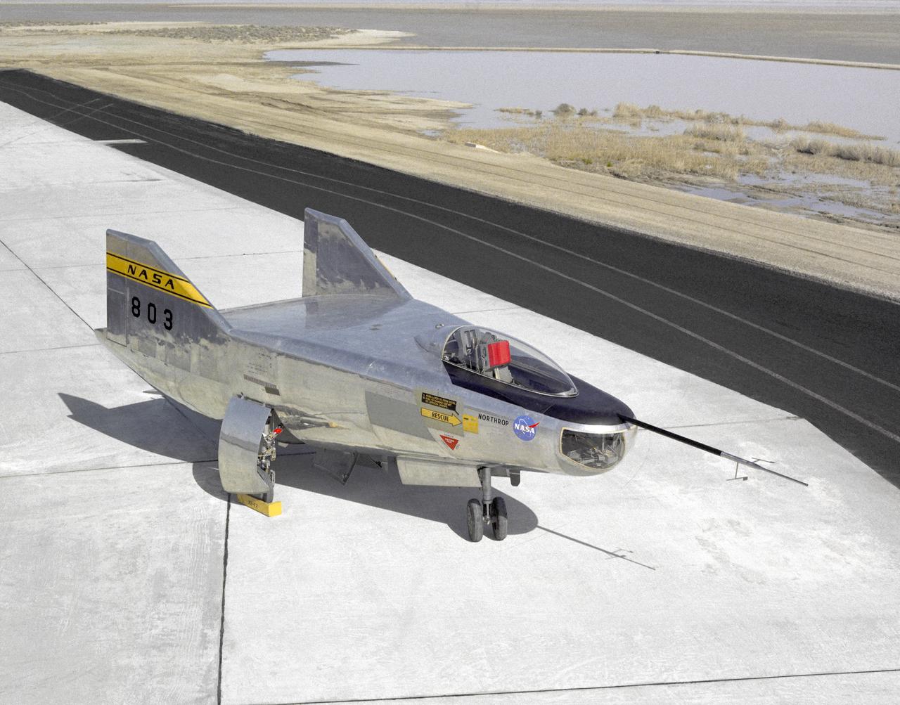
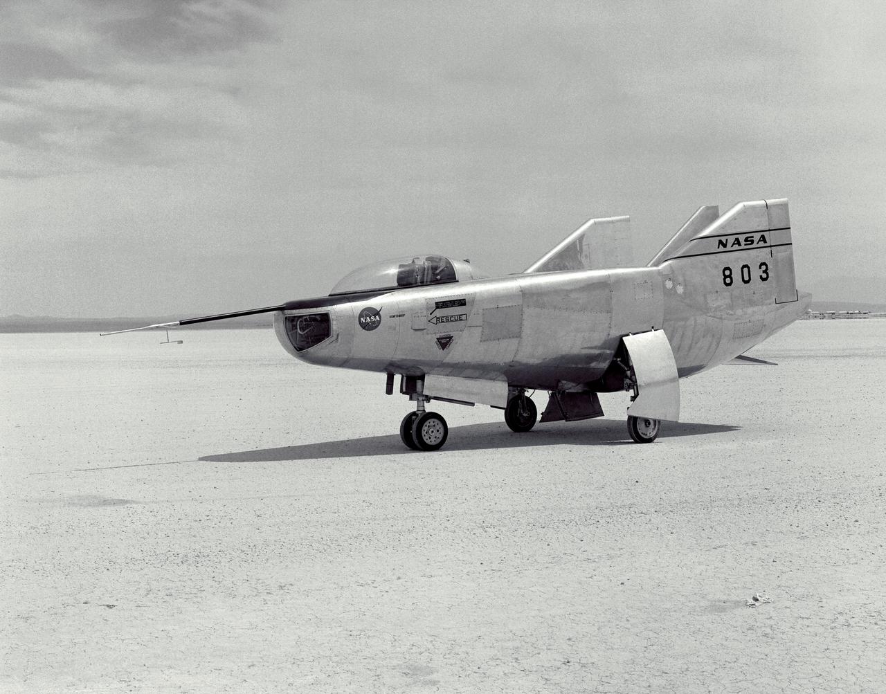
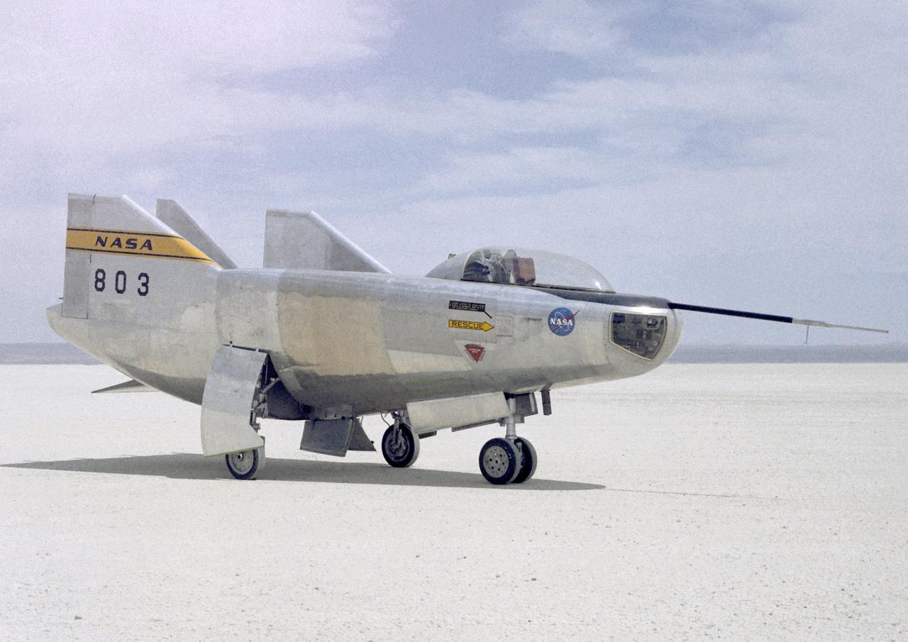
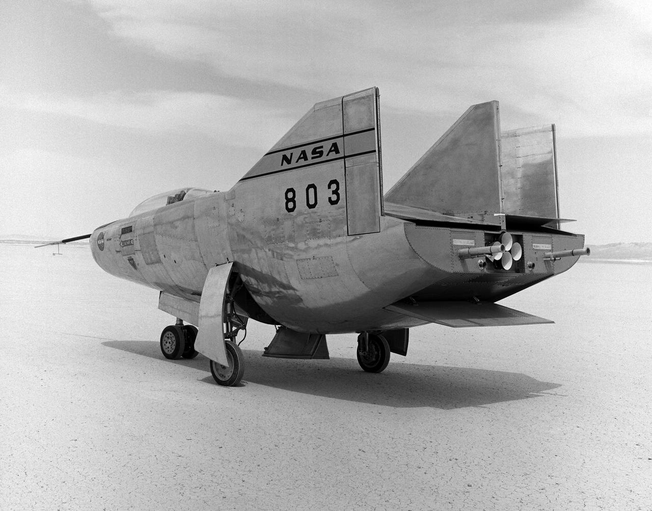
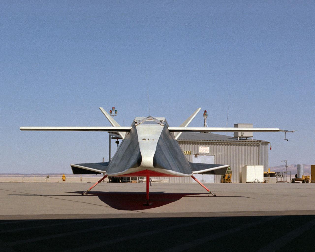
This side-rear view of the X-24A Lifting Body on the lakebed by the NASA Flight Research Center shows its control surfaces used for subsonic flight.
The M2-F2 Lifting Body is seen here on the ramp at the NASA Dryden Flight Research Center. The success of Dryden's M2-F1 program led to NASA's development and construction of two heavyweight lifting bodies based on studies at NASA's Ames and Langley research centers -- the M2-F2 and the HL-10, both built by the Northrop Corporation. The "M" refers to "manned" and "F" refers to "flight" version. "HL" comes from "horizontal landing" and 10 is for the tenth lifting body model to be investigated by Langley. The first flight of the M2-F2 -- which looked much like the "F1" -- was on July 12, 1966. Milt Thompson was the pilot. By then, the same B-52 used to air launch the famed X-15 rocket research aircraft was modified to also carry the lifting bodies. Thompson was dropped from the B-52's wing pylon mount at an altitude of 45,000 feet on that maiden glide flight. The M2-F2 weighed 4,620 pounds, was 22 feet long, and had a width of about 10 feet. On May 10, 1967, during the sixteenth glide flight leading up to powered flight, a landing accident severely damaged the vehicle and seriously injured the NASA pilot, Bruce Peterson. NASA pilots and researchers realized the M2-F2 had lateral control problems, even though it had a stability augmentation control system. When the M2-F2 was rebuilt at Dryden and redesignated the M2-F3, it was modified with an additional third vertical fin -- centered between the tip fins -- to improve control characteristics. The M2-F2/F3 was the first of the heavy-weight, entry-configuration lifting bodies. Its successful development as a research test vehicle answered many of the generic questions about these vehicles. NASA donated the M2-F3 vehicle to the Smithsonian Institute in December 1973. It is currently hanging in the Air and Space Museum along with the X-15 aircraft number 1, which was its hangar partner at Dryden from 1965 to 1969.
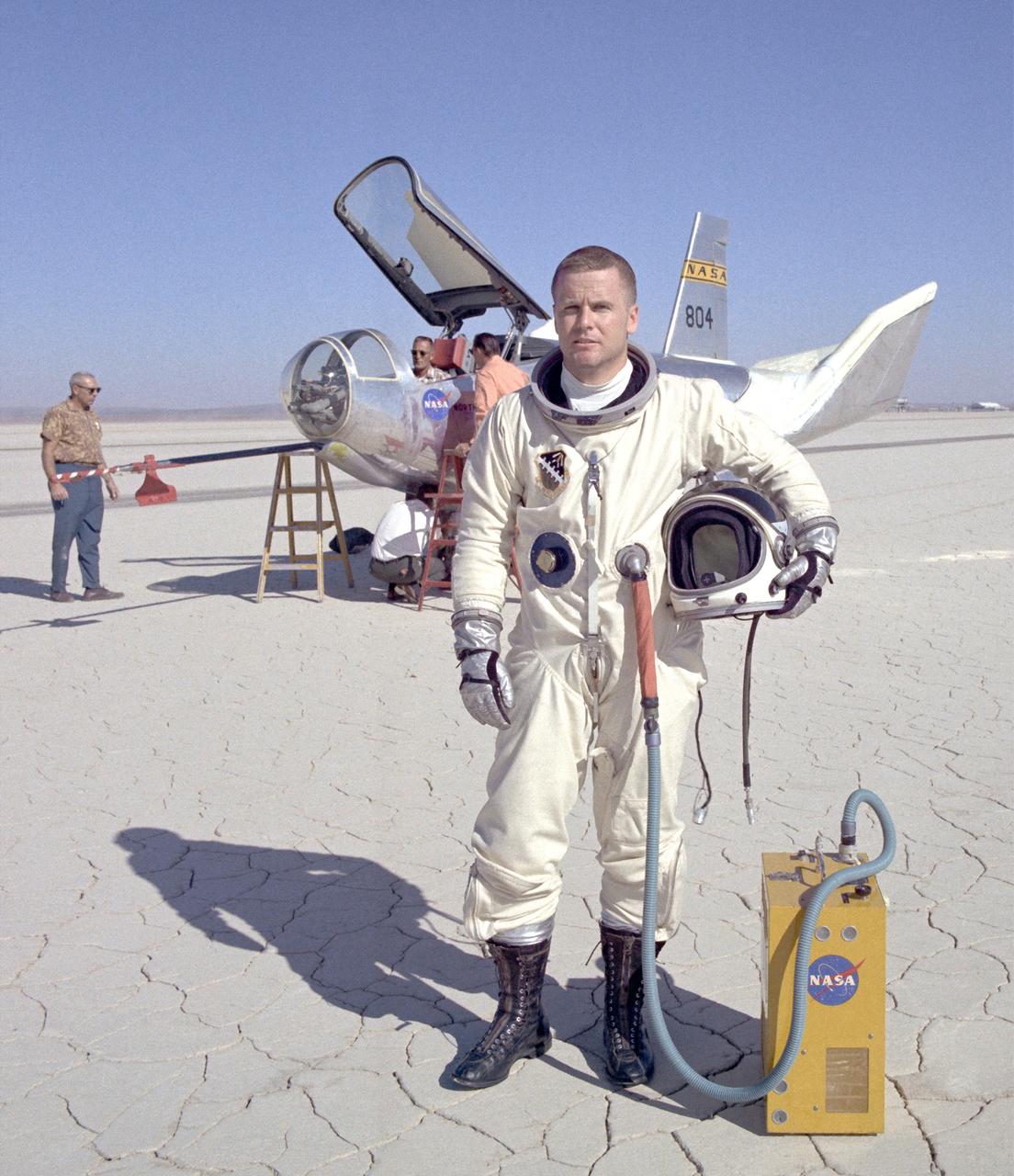
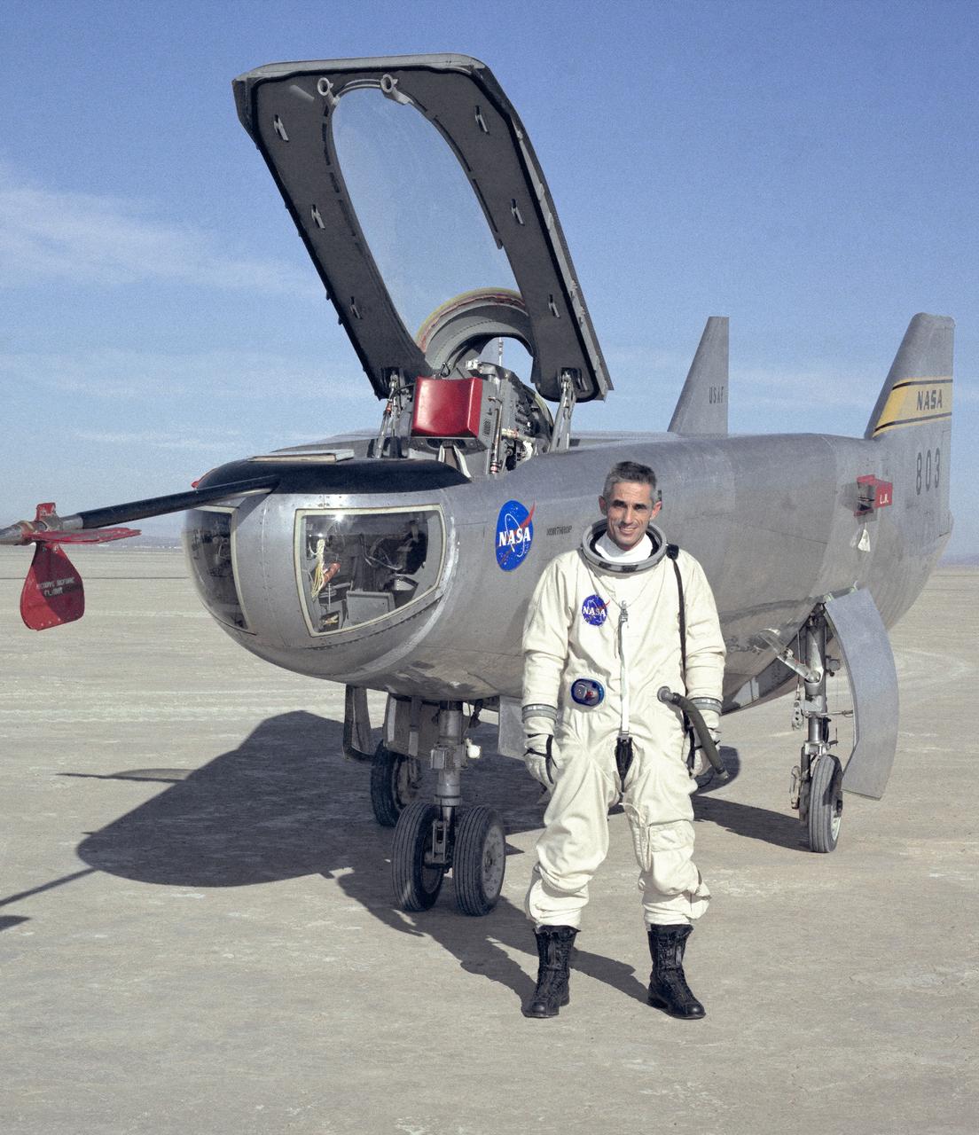
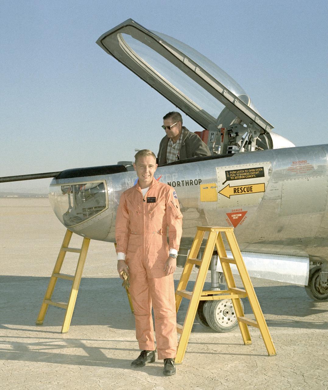
Air Force Major Peter Hoag stands in front of the HL-10 Lifting Body. Maj. Hoag joined the HL-10 program in 1969 and made his first glide flight on June 6, 1969. He made a total of 8 flights in the HL-10. They included the fastest lifting-body flight, which reached Mach 1.861 on Feb. 18, 1970.
The HL-10 was one of five heavyweight lifting-body designs flown at NASA's Flight Research Center (FRC--later Dryden Flight Research Center), Edwards, California, from July 1966 to November 1975 to study and validate the concept of safely maneuvering and landing a low lift-over-drag vehicle designed for reentry from space. Northrop Corporation built the HL-10 and M2-F2, the first two of the fleet of "heavy" lifting bodies flown by the NASA Flight Research Center. The contract for construction of the HL-10 and the M2-F2 was $1.8 million. "HL" stands for horizontal landing, and "10" refers to the tenth design studied by engineers at NASA's Langley Research Center, Hampton, Va. After delivery to NASA in January 1966, the HL-10 made its first flight on Dec. 22, 1966, with research pilot Bruce Peterson in the cockpit. Although an XLR-11 rocket engine was installed in the vehicle, the first 11 drop flights from the B-52 launch aircraft were powerless glide flights to assess handling qualities, stability, and control. In the end, the HL-10 was judged to be the best handling of the three original heavy-weight lifting bodies (M2-F2/F3, HL-10, X-24A). The HL-10 was flown 37 times during the lifting body research program and logged the highest altitude and fastest speed in the Lifting Body program. On Feb. 18, 1970, Air Force test pilot Peter Hoag piloted the HL-10 to Mach 1.86 (1,228 mph). Nine days later, NASA pilot Bill Dana flew the vehicle to 90,030 feet, which became the highest altitude reached in the program. Some new and different lessons were learned through the successful flight testing of the HL-10. These lessons, when combined with information from it's sister ship, the M2-F2/F3, provided an excellent starting point for designers of future entry vehicles, including the Space Shuttle.
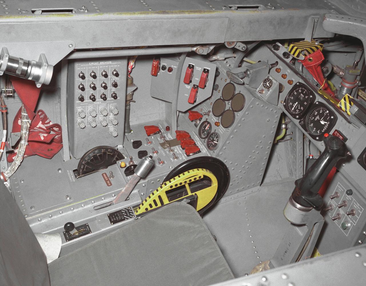
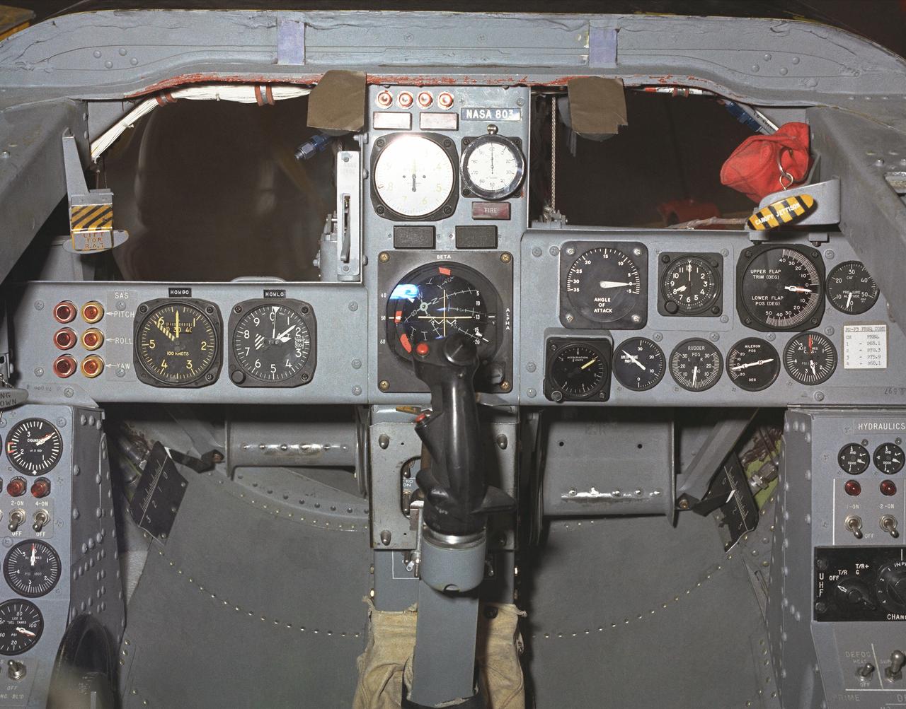
This photo shows the left side cockpit instrumentation panel of the M2-F2 Lifting Body. The success of Dryden's M2-F1 program led to NASA's development and construction of two heavyweight lifting bodies based on studies at NASA's Ames and Langley research centers -- the M2-F2 and the HL-10, both built by the Northrop Corporation. The "M" refers to "manned" and "F" refers to "flight" version. "HL" comes from "horizontal landing" and 10 is for the tenth lifting body model to be investigated by Langley. The first flight of the M2-F2 -- which looked much like the "F1" -- was on July 12, 1966. Milt Thompson was the pilot. By then, the same B-52 used to air launch the famed X-15 rocket research aircraft was modified to also carry the lifting bodies. Thompson was dropped from the B-52's wing pylon mount at an altitude of 45,000 feet on that maiden glide flight. The M2-F2 weighed 4,620 pounds, was 22 feet long, and had a width of about 10 feet. On May 10, 1967, during the sixteenth glide flight leading up to powered flight, a landing accident severely damaged the vehicle and seriously injured the NASA pilot, Bruce Peterson. NASA pilots and researchers realized the M2-F2 had lateral control problems, even though it had a stability augmentation control system. When the M2-F2 was rebuilt at Dryden and redesignated the M2-F3, it was modified with an additional third vertical fin -- centered between the tip fins -- to improve control characteristics. The M2-F2/F3 was the first of the heavy-weight, entry-configuration lifting bodies. Its successful development as a research test vehicle answered many of the generic questions about these vehicles. NASA donated the M2-F3 vehicle to the Smithsonian Institute in December 1973. It is currently hanging in the Air and Space Museum along with the X-15 aircraft number 1, which was its hangar partner at Dryden from 1965 to 1969.
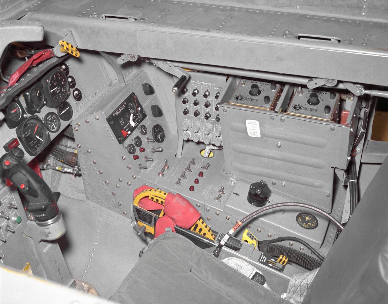
This photo shows the right side cockpit instrumentation panel of the M2-F2 Lifting Body. The success of Dryden's M2-F1 program led to NASA's development and construction of two heavyweight lifting bodies based on studies at NASA's Ames and Langley research centers -- the M2-F2 and the HL-10, both built by the Northrop Corporation. The "M" refers to "manned" and "F" refers to "flight" version. "HL" comes from "horizontal landing" and 10 is for the tenth lifting body model to be investigated by Langley. The first flight of the M2-F2 -- which looked much like the "F1" -- was on July 12, 1966. Milt Thompson was the pilot. By then, the same B-52 used to air launch the famed X-15 rocket research aircraft was modified to also carry the lifting bodies. Thompson was dropped from the B-52's wing pylon mount at an altitude of 45,000 feet on that maiden glide flight. The M2-F2 weighed 4,620 pounds, was 22 feet long, and had a width of about 10 feet. On May 10, 1967, during the sixteenth glide flight leading up to powered flight, a landing accident severely damaged the vehicle and seriously injured the NASA pilot, Bruce Peterson. NASA pilots and researchers realized the M2-F2 had lateral control problems, even though it had a stability augmentation control system. When the M2-F2 was rebuilt at Dryden and redesignated the M2-F3, it was modified with an additional third vertical fin -- centered between the tip fins -- to improve control characteristics. The M2-F2/F3 was the first of the heavy-weight, entry-configuration lifting bodies. Its successful development as a research test vehicle answered many of the generic questions about these vehicles. NASA donated the M2-F3 vehicle to the Smithsonian Institute in December 1973. It is currently hanging in the Air and Space Museum along with the X-15 aircraft number 1, which was its hangar partner at Dryden from 1965 to 1969.
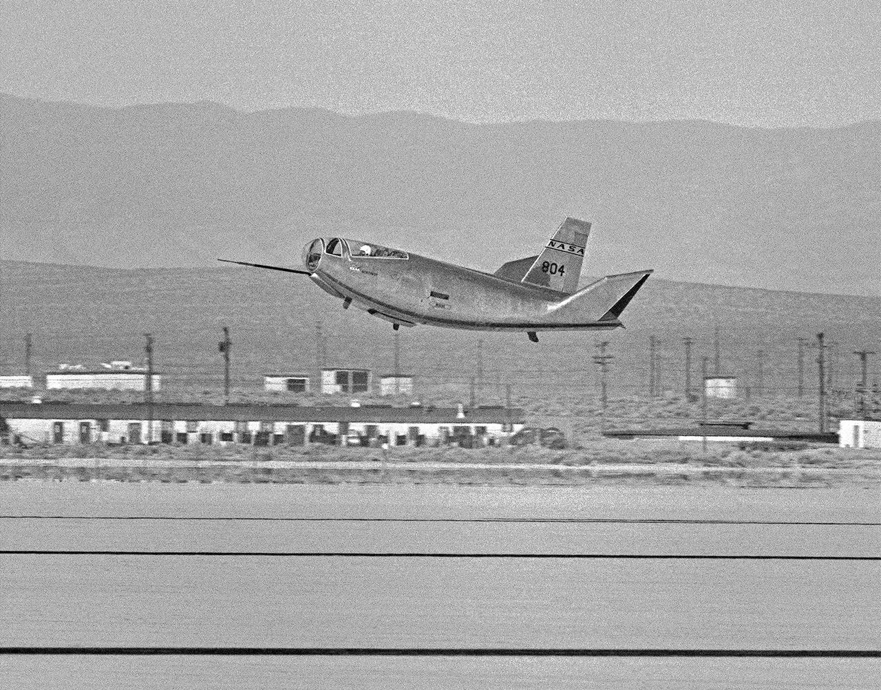
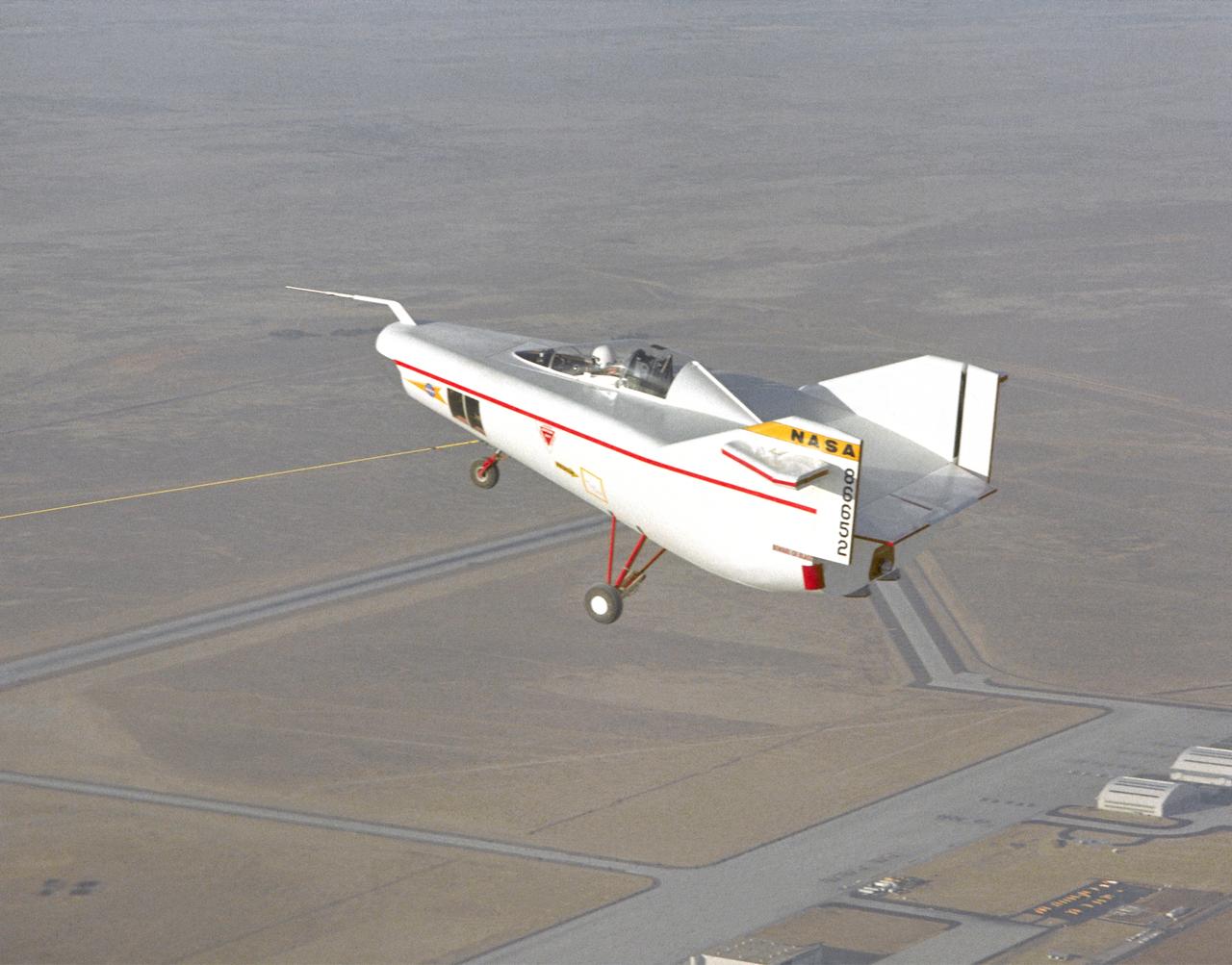
The HL-10 Lifting Body is seen here in flight over Rogers Dry lakebed. Like the other lifting bodies, the HL-10 made a steep descent toward the lakebed, followed by a high-speed landing. This was due to the vehicle's low lift-over-drag ratio. The first 11 flights of the HL-10 were unpowered, flown to check the vehicle's handling and stability before rocket-powered flights began using the XLR-11 rocket engine.
The HL-10 lifting body is seen here in flight over Rogers Dry Lake at Edwards AFB. After the vehicle's fins were modified following its first flight, the HL-10 proved to be the best handling of the heavy-weight lifting bodies flown at Edwards Air Force Base. The HL-10 flew much better than the M2-F2, and pilots were eager to fly it.
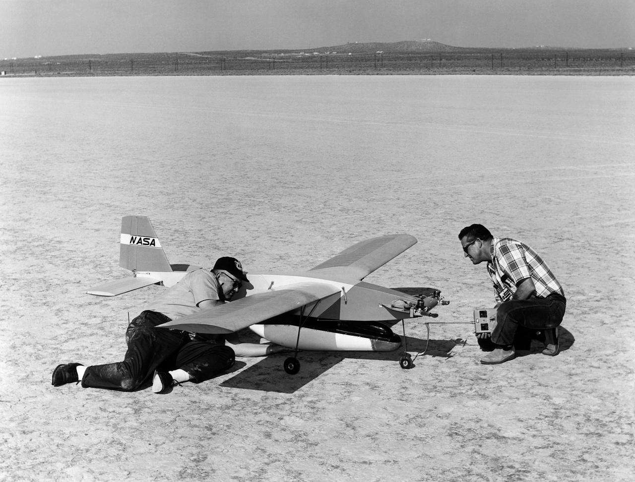
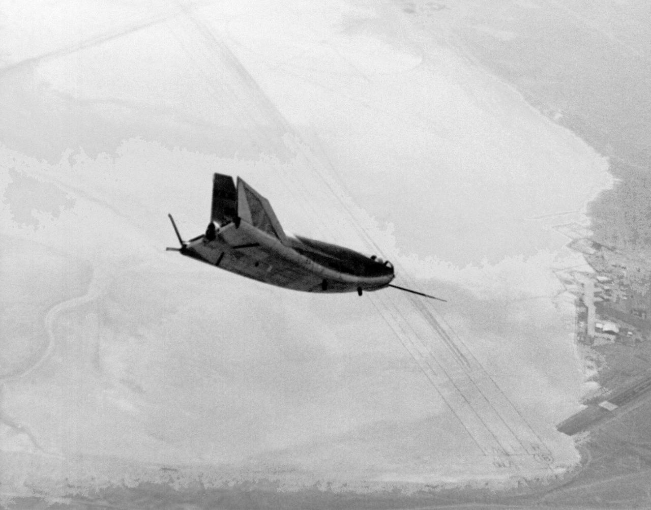
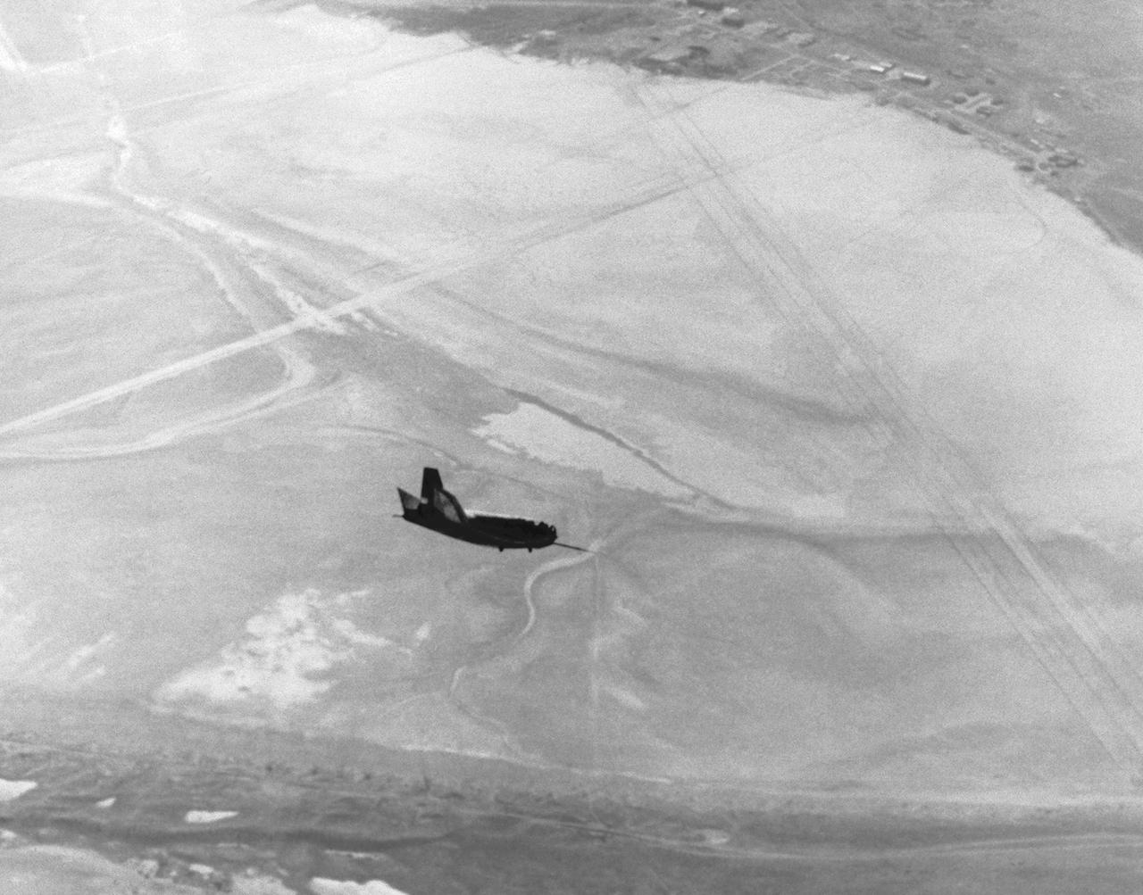
A photo of model airplane builders James B. Newman and Robert L. McDonald preparing for a flight with models of the M2-F2 and a “Mothership”. In 1968 a test flight was made on the Rosamond dry lakebed, Rosamond, California. The original idea of lifting bodies was conceived about 1957 by Dr. Alfred J. Eggers, Jr., then the assistant director for Research and Development Analysis and Planning at the National Advisory Committee for Aeronautics' Ames Aeronautical Laboratory, Moffett Field, California. Nose cone studies led to the design known as the M-2, a modified half-cone, rounded on the bottom and flat on top, with a blunt, rounded nose and twin tail fins. To gather flight data on this configuration, models were found to be an effective method. A special twin-engined, 14-foot model “mothership” was used for carrying the M2-F2 model to altitude and a launch, much as was being done with the B-52 for the full-scale lifting bodies. Jim (on the left) will fly the “mothership” and Bob will take control of the M2-F2 at launch and fly it to a landing on the lakebed.
John Manke is shown here on the lakebed next to the HL-10, one of four different lifting-body vehicles he flew, including the X-24B, which he flew 16 times. His final total was 42 lifting-body flights.
This photo shows the cockpit instrument panel of the M2-F3 Lifting Body.
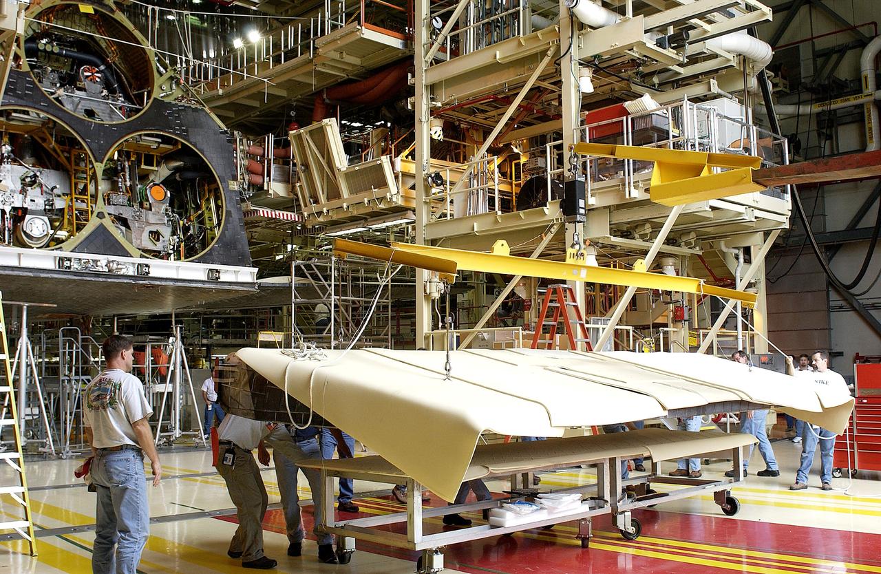
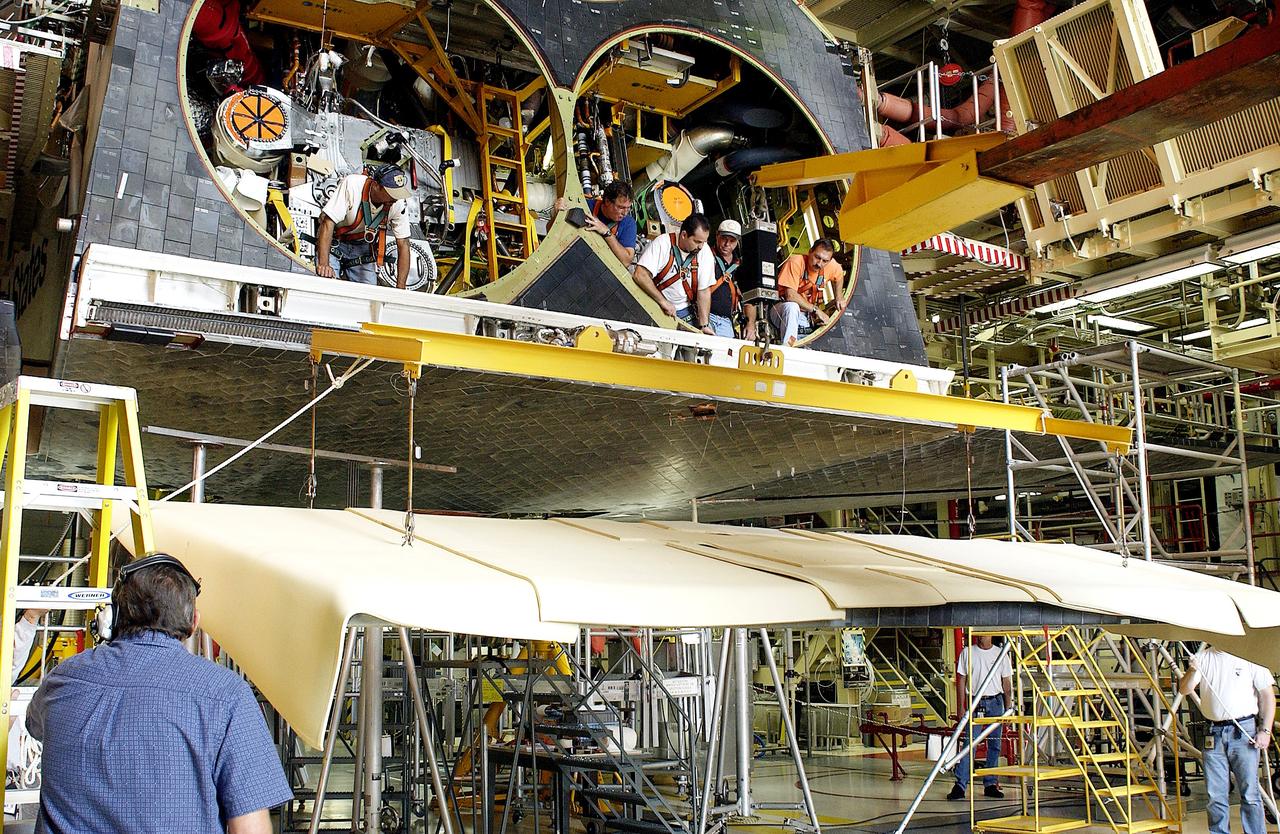
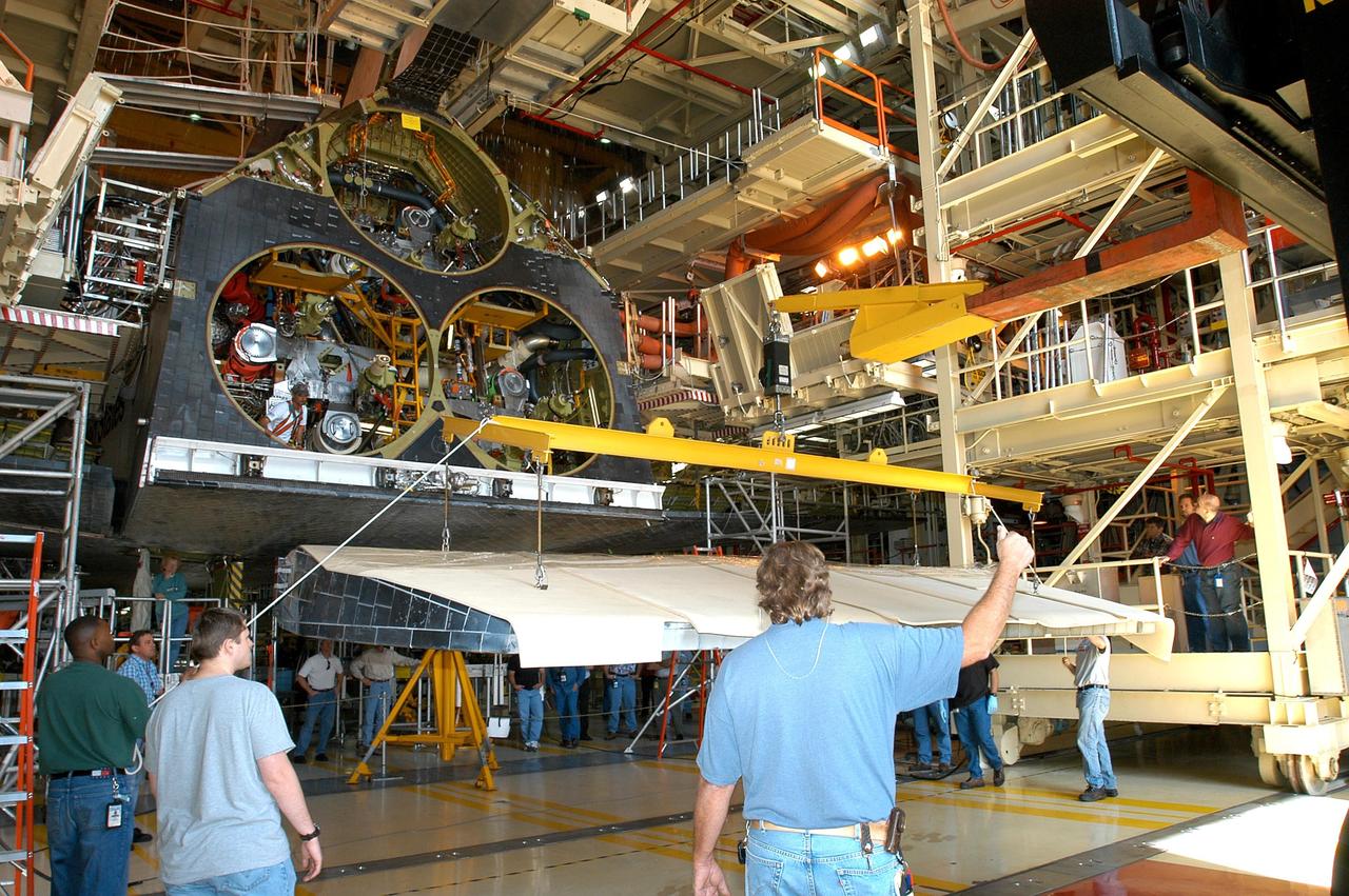
KENNEDY SPACE CENTER, FLA. - Workers in the Orbiter Processing Facility get ready to lift and install the rear body flap on orbiter Discovery. The body flap, which is temporarily under protective covering, attaches below the main engines.
KENNEDY SPACE CENTER, FLA. - Workers in the Orbiter Processing Facility get ready to lift and install the rear body flap on orbiter Discovery. The body flap, which is temporarily under protective covering, attaches below the main engines.
KENNEDY SPACE CENTER, FLA. - Workers in the Orbiter Processing Facility get ready to lift and install the rear body flap on orbiter Discovery. The body flap, which is temporarily under protective covering, attaches below the main engines.
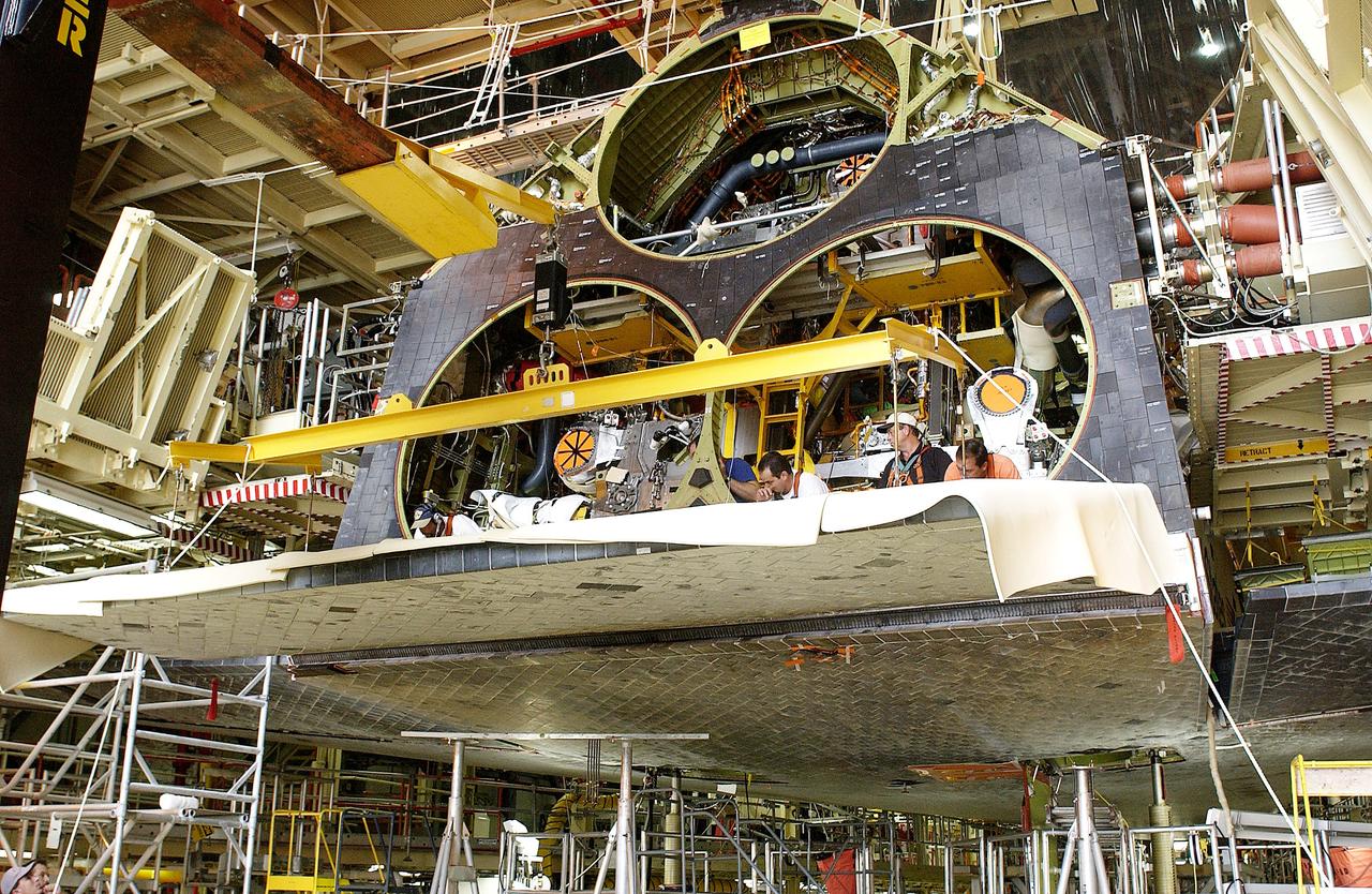
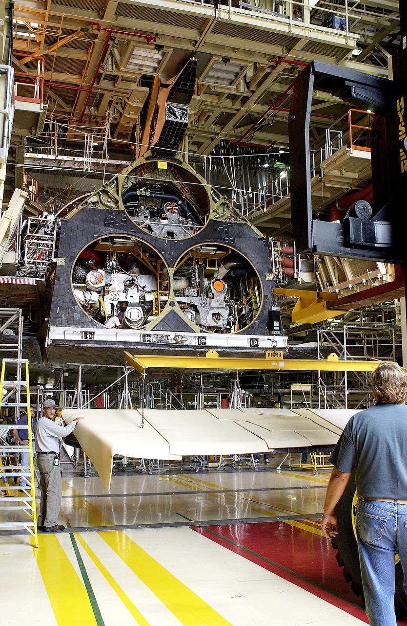
KENNEDY SPACE CENTER, FLA. - In the Orbiter Processing Facility, the rear body flap is lifted into place on the orbiter Discovery. The body flap, which is temporarily under protective covering, attaches below the main engines.
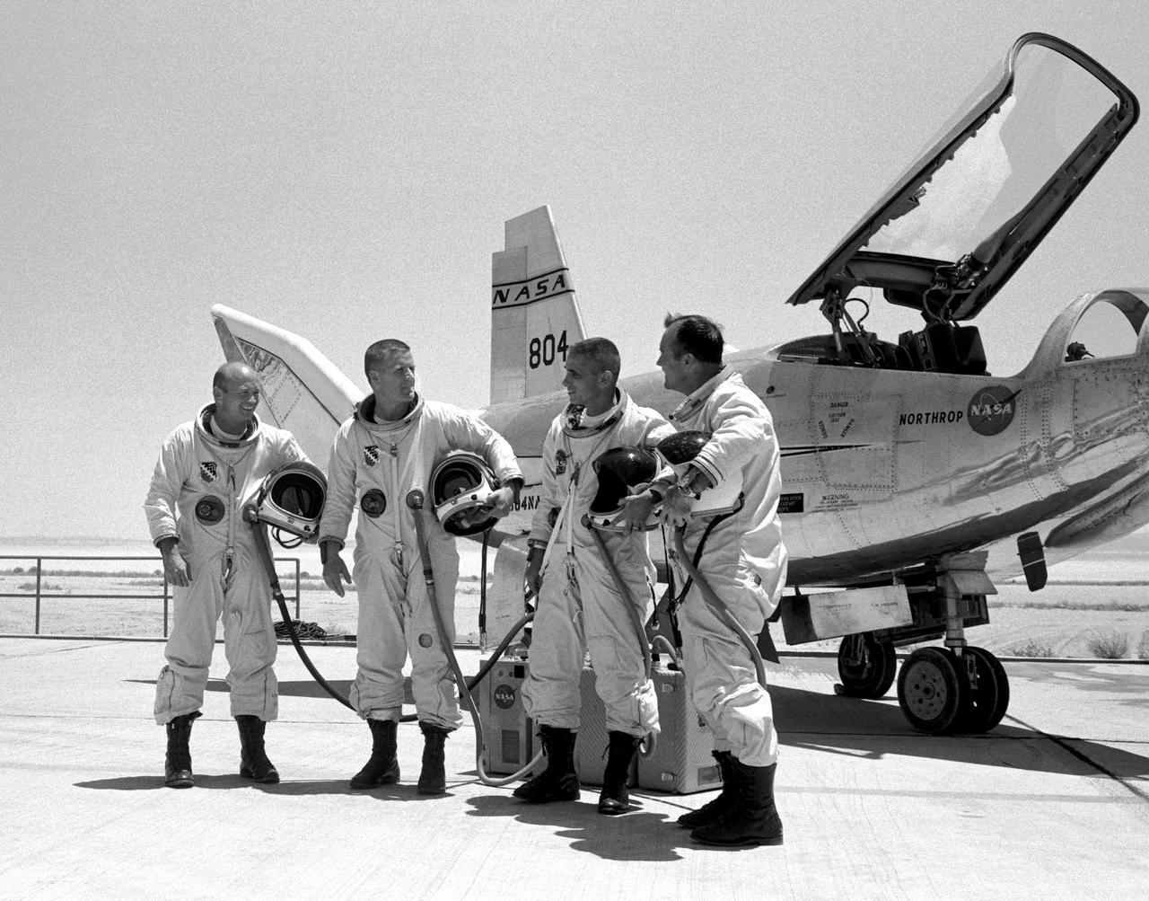
The four principal HL-10 pilots are seen here with the lifting body aircraft. They are, left to right; Air Force Major Jerauld R. Gentry, Air Force test pilot Peter Hoag, and NASA pilots John A. Manke and Bill Dana. All are wearing the pressure suits needed for flying above 50,000 feet.
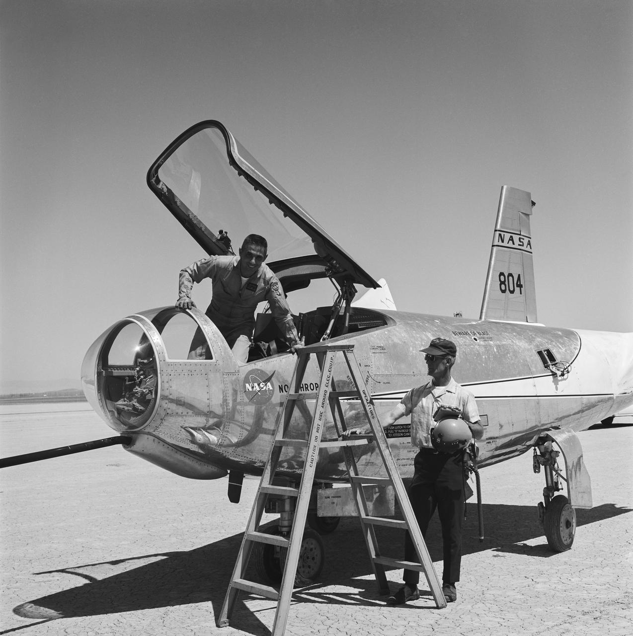
Armstrong research pilot (and future center director) John Manke emerges from the HL-10, NASA Langley’s 10th horizontal lander (lifting body).
NASA research pilot Milt Thompson is helped into the cockpit of the M2-F2 lifting body research aircraft at NASA’s Flight Research Center (now the Dryden Flight Research Center). The M2-F2 is attached to a wing pylon under the wing of NASA’s B-52 mothership. The flight was a captive flight with the pilot on-board. Milt Thompson flew in the lifting body throughout the flight, but it was never dropped from the mothership.
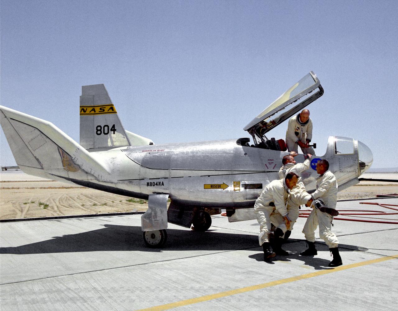
Not every moment of a test pilot's day is serious business. In a moment of levity, NASA pilots Bill Dana (left) and John A. Manke try to drag Air Force test pilot Peter Hoag away from the HL-10 lifting body while Air Force Major Jerauld R. Gentry helps from the cockpit. These four men were the principal pilots for the HL-10 program. This was not the only prank involving the HL-10 and its pilots. Once "Captain Midnight" (Gentry) and the "Midnight Skulkers" sneaked into the NASA hangar and put "U.S. Air Force" on the aircraft using stick-on letters. Later, while Gentry was making a lifting-body flight, his 1954 Ford was "borrowed" from the parking lot, painted with yellow-green zinc-chromate primer, and decorated with large stick-on flowers about one foot in diameter. After Gentry returned from the flight, he was surprised to see what had happened to his car.
The HL-10 Lifting Body completes its first research flight with a landing on Rogers Dry Lake at Edwards AFB, California, on December 22, 1966. The HL-10 suffered from buffeting and poor control during the flight. Pilot Bruce Peterson was able to make a successful landing despite the severe problems. These were traced to airflow separation from the fins. As a result, the fins were no longer able to stabilize the vehicle. A small reshaping of the fins' leading edges cured the airflow separation, but it was not until March 15, 1968, that the second HL-10 flight occurred.
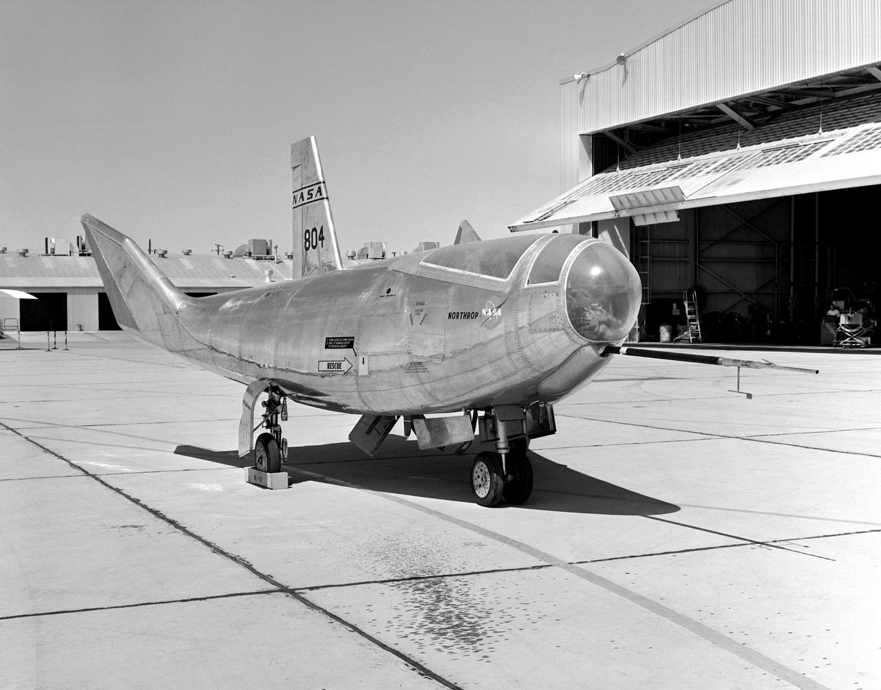
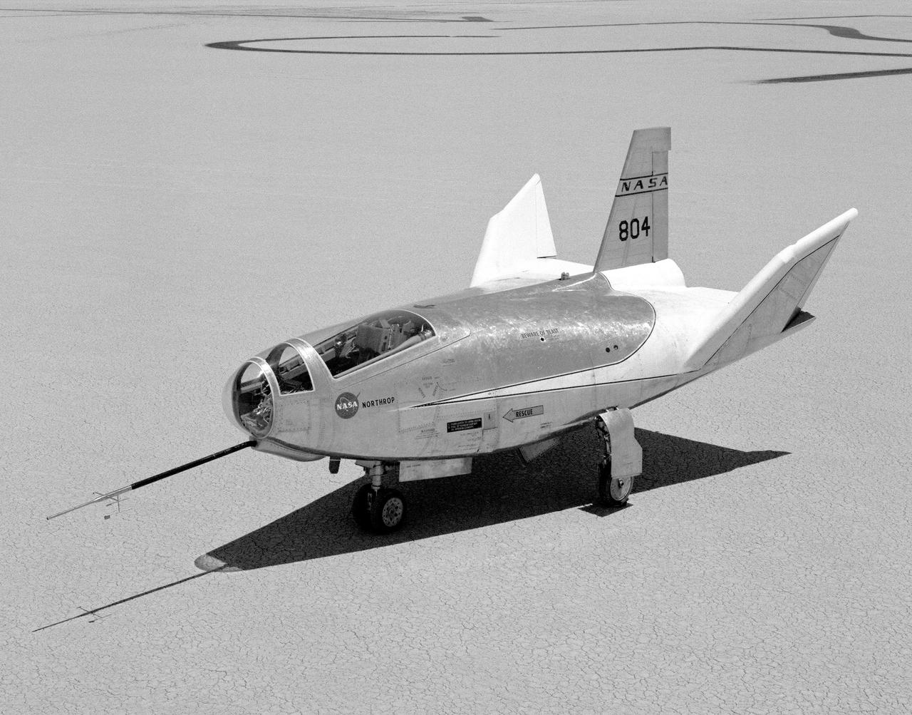
The HL-10, seen here parked on the ramp, was one of five lifting body designs flown at NASA's Dryden Flight Research Center, Edwards, California, from July 1966 to November 1975 to study and validate the concept of safely maneuvering and landing a low lift-over-drag vehicle designed for reentry from space.
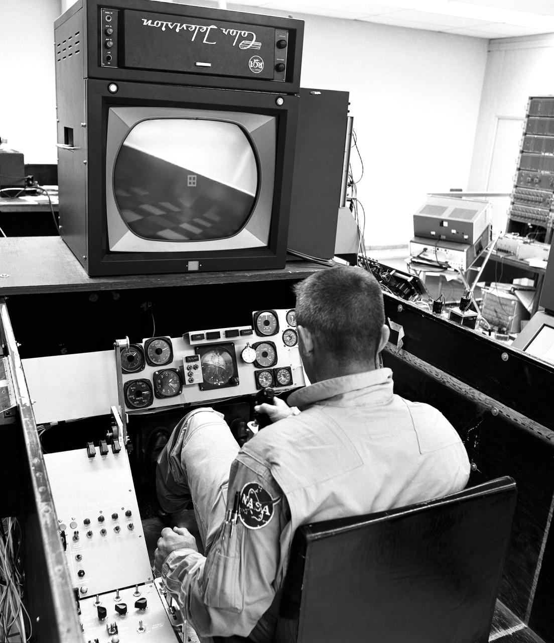
As shown in this photo of the HL-10 flight simulator, the lifting-body pilots and engineers made use of early simulators for both training and the determination of a given vehicle's handling at various speeds, attitudes, and altitudes. This provided warning of possible problems.
A unique, close-up view of the X-38 under the wing of NASA's B-52 mothership prior to launch of the lifting-body research vehicle. The photo was taken from the observation window of the B-52 bomber as it banked in flight.
The Hyper III was a full-scale lifting-body remotely piloted research vehicle (RPRV) built at what was then the NASA Flight Research Center located at Edwards Air Force Base in Southern California.
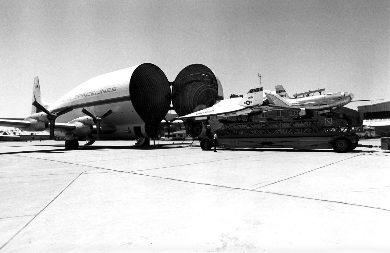
Aero Spacelines B377SGT Super Guppy on Ramp Loading the X-24B and HL-10 Lifting Bodies for Transportation to the Air Force Museum at Wright-Patterson Air Force Base, Ohio

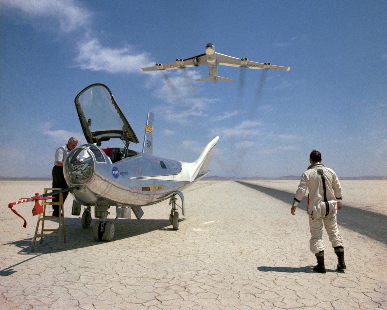
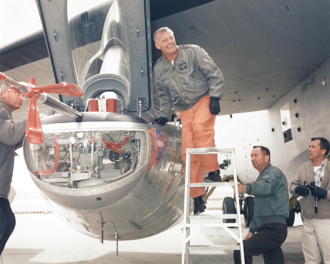
NASA research pilot Bill Dana stands in front of the HL-10 Lifting Body following his first glide flight on April 25, 1969. Dana later retired as Chief Engineer at NASA's Dryden Flight Research Center, (called the NASA Flight Research Center in 1969). Prior to his lifting body assignment, Dana flew the X-15 research airplane. He flew the rocket-powered aircraft 16 times, reaching a top speed of 3,897 miles per hour and a peak altitude of 310,000 feet (almost 59 miles high).
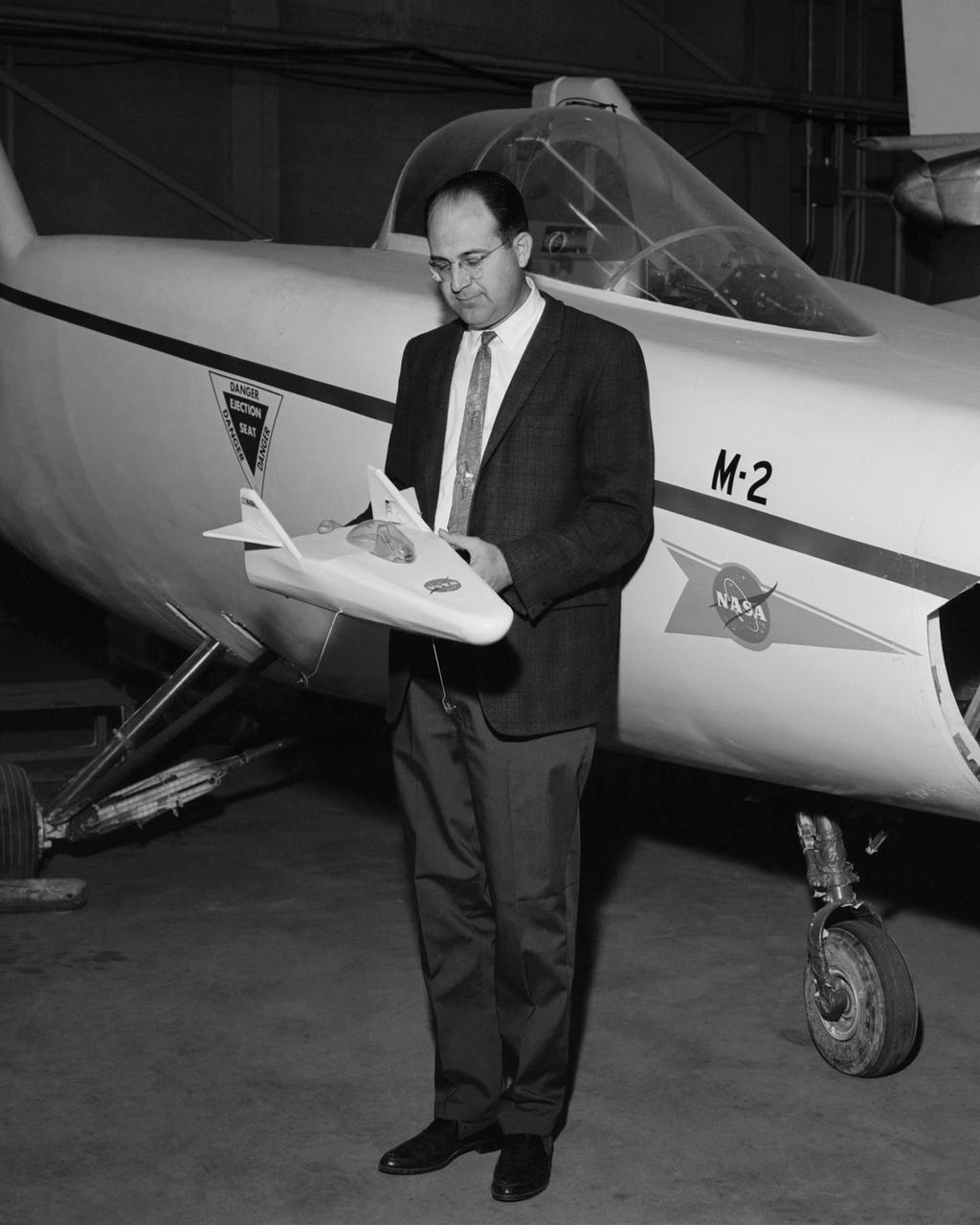
Dale Reed with a model of the M2-F1 in front of the actual lifting body. Reed used the model to show the potential of the lifting bodies. He first flew it into tall grass to test stability and trim, then hand-launched it from buildings for longer flights. Finally, he towed the lifting-body model aloft using a powered model airplane known as the "Mothership." A timer released the model and it glided to a landing. Dale's wife Donna used a 9 mm. camera to film the flights of the model. Its stability as it glided--despite its lack of wings--convinced Milt Thompson and some Flight Research Center engineers including the center director, Paul Bikle, that a piloted lifting body was possible.
KENNEDY SPACE CENTER, FLA. - In the Orbiter Processing Facility, workers look down from spaces allotted for the main engines as the rear body flap is lifted for installation on the orbiter Discovery. The body flap, which is temporarily under protective covering, attaches below the main engines.
The M2-F1 Lifting Body is seen here under tow by an unseen C-47 at the NASA Flight Research Center (later redesignated the Dryden Flight Research Center), Edwards, California. The low-cost vehicle was the first piloted lifting body to be test flown. The lifting-body concept originated in the mid-1950s at the National Advisory Committee for Aeronautics' Ames Aeronautical Laboratory, Mountain View California. By February 1962, a series of possible shapes had been developed, and R. Dale Reed was working to gain support for a research vehicle.
The HL-10 Lifting Body is seen here parked on Rogers Dry Lake, the unique location where it landed after research flights. This 1968 photo shows the vehicle after the fins were modified to remove instabilities encountered on the first flight. It involved a change to the shape of the leading edge of the fins to eliminate flow separation. It required extensive wind-tunnel testing at Langley Research Center, Hampton, Va. NASA Flight Research Center (FRC) engineer Bob Kempel than plotted thousands of data points by hand to come up with the modification, which involved a fiberglass glove backed with a metal structure on each fin's leading edge. This transformed the vehicle from a craft that was difficult to control into the best handling of the original group of lifting bodies at the FRC.
NASA research pilot John A. Manke is seen here in front of the M2-F3 Lifting Body. Manke was hired by NASA on May 25, 1962, as a flight research engineer. He was later assigned to the pilot's office and flew various support aircraft including the F-104, F5D, F-111 and C-47. After leaving the Marine Corps in 1960, Manke worked for Honeywell Corporation as a test engineer for two years before coming to NASA. He was project pilot on the X-24B and also flew the HL-10, M2-F3, and X-24A lifting bodies. John made the first supersonic flight of a lifting body and the first landing of a lifting body on a hard surface runway. Manke served as Director of the Flight Operations and Support Directorate at the Dryden Flight Research Center prior to its integration with Ames Research Center in October 1981. After this date John was named to head the joint Ames-Dryden Directorate of Flight Operations. He also served as site manager of the NASA Ames-Dryden Flight Research Facility. John is a member of the Society of Experimental Test Pilots. He retired on April 27, 1984.
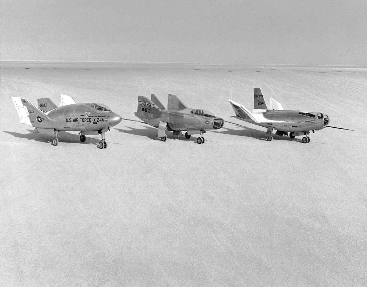
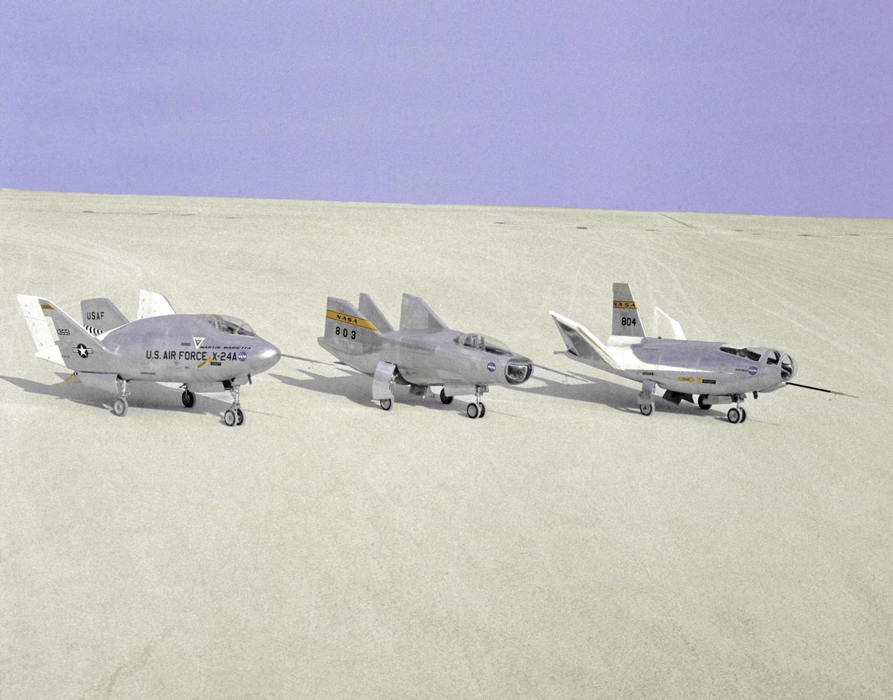
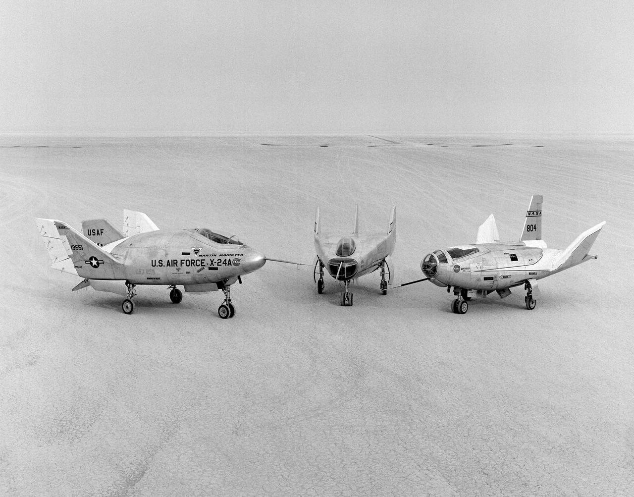
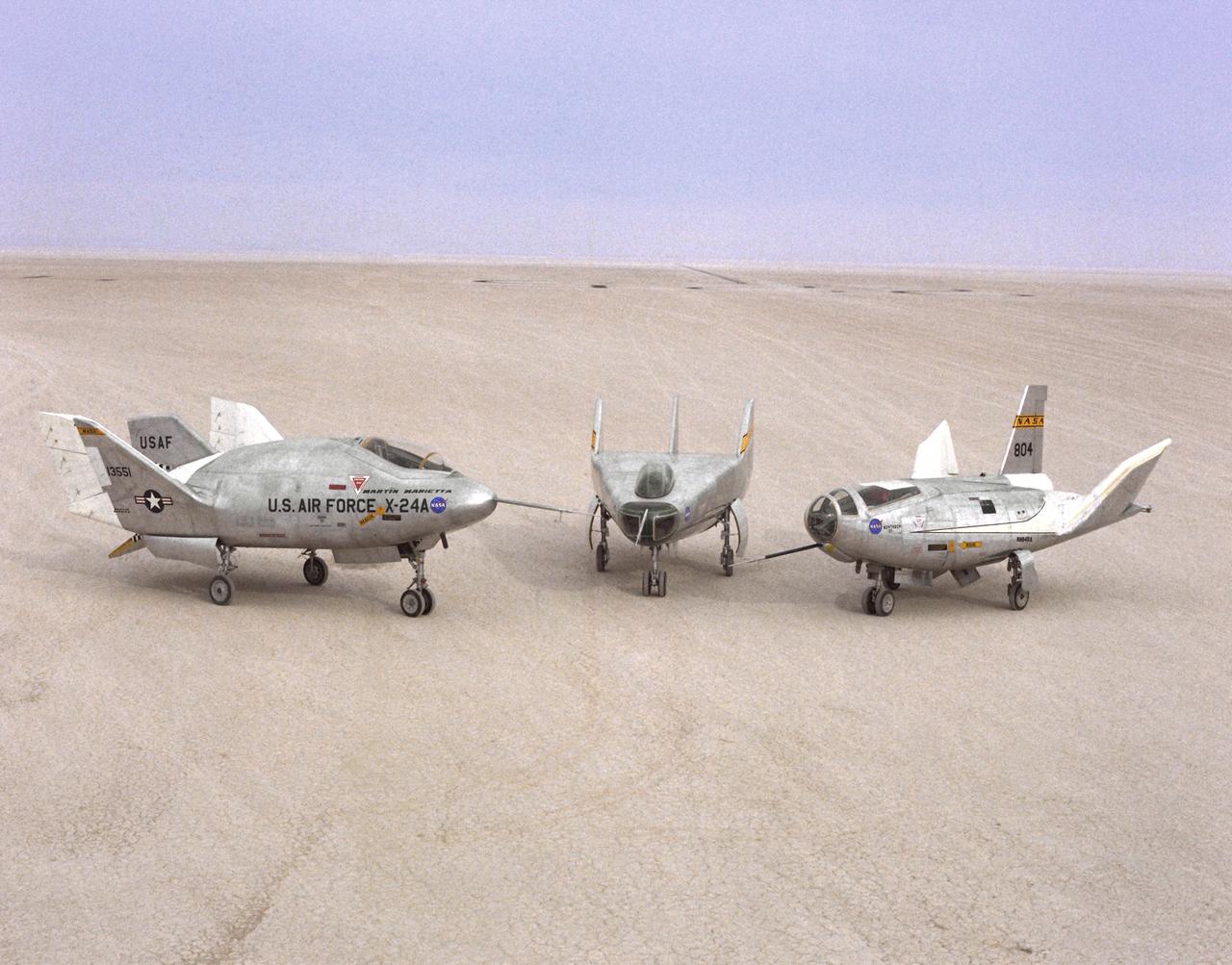
The wingless, lifting body aircraft sitting on Rogers Dry Lake at what is now NASA's Dryden Flight Research Center, Edwards, California, from left to right are the X-24A, M2-F3 and the HL-10. The lifting body aircraft studied the feasibility of maneuvering and landing an aerodynamic craft designed for reentry from space. These lifting bodies were air launched by a B-52 mother ship, then flew powered by their own rocket engines before making an unpowered approach and landing. They helped validate the concept that a space shuttle could make accurate landings without power. The X-24A flew from April 17, 1969 to June 4, 1971. The M2-F3 flew from June 2, 1970 until December 20, 1972. The HL-10 flew from December 22, 1966 until July 17, 1970 and logged the highest and fastest records in the lifting body program.
The wingless, lifting body aircraft sitting on Rogers Dry Lake at what is now NASA's Dryden Flight Research Center, Edwards, California, from left to right are the X-24A, M2-F3 and the HL-10. The lifting body aircraft studied the feasibility of maneuvering and landing an aerodynamic craft designed for reentry from space. These lifting bodies were air launched by a B-52 mother ship, then flew powered by their own rocket engines before making an unpowered approach and landing. They helped validate the concept that a space shuttle could make accurate landings without power. The X-24A flew from April 17, 1969 to June 4, 1971. The M2-F3 flew from June 2, 1970 until December 21, 1971. The HL-10 flew from December 22, 1966 until July 17, 1970, and logged the highest and fastest records in the lifting body program.
The wingless, lifting body aircraft sitting on Rogers Dry Lake at what is now NASA's Dryden Flight Research Center, Edwards, California, from left to right are the X-24A, M2-F3 and the HL-10. The lifting body aircraft studied the feasibility of maneuvering and landing an aerodynamic craft designed for reentry from space. These lifting bodies were air launched by a B-52 mother ship, then flew powered by their own rocket engines before making an unpowered approach and landing. They helped validate the concept that a space shuttle could make accurate landings without power. The X-24A flew from April 17, 1969 to June 4, 1971. The M2-F3 flew from June 2, 1970 until December 20, 1972. The HL-10 flew from December 22, 1966 until July 17, 1970 and logged the highest and fastest records in the lifting body program.
The wingless, lifting body aircraft sitting on Rogers Dry Lake at what is now NASA's Dryden Flight Research Center, Edwards, California, from left to right are the X-24A, M2-F3 and the HL-10. The lifting body aircraft studied the feasibility of maneuvering and landing an aerodynamic craft designed for reentry from space. These lifting bodies were air launched by a B-52 mother ship, then flew powered by their own rocket engines before making an unpowered approach and landing. They helped validate the concept that a space shuttle could make accurate landings without power. The X-24A flew from April 17, 1969 to June 4, 1971. The M2-F3 flew from June 2, 1970 until December 22, 1972. The HL-10 flew from December 22, 1966 until July 17, 1970, and logged the highest and fastest records in the lifting body program.
The M2-F3 Lifting Body is seen here on the lakebed at the NASA Flight Research Center (FRC--later the Dryden Flight Research Center), Edwards, California. After a three-year-long redesign and rebuilding effort, the M2-F3 was ready to fly. The May 1967 crash of the M2-F2 had damaged both the external skin and the internal structure of the lifting body. At first, it seemed that the vehicle had been irreparably damaged, but the original manufacturer, Northrop, did the repair work and returned the redesigned M2-F3 with a center fin for stability to the FRC.
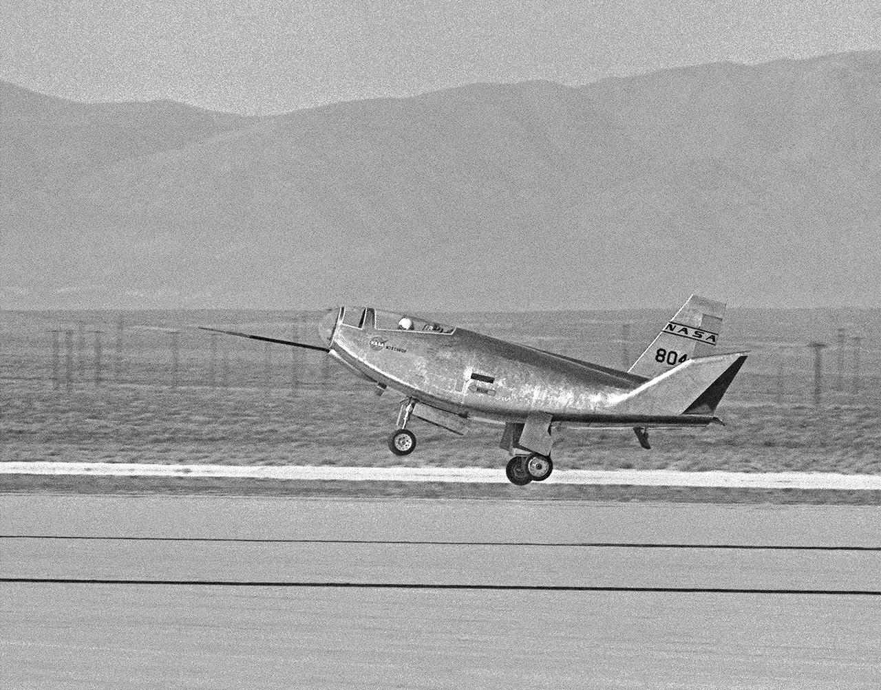
The HL-10 Lifting Body completes its first research flight with a landing on Rogers Dry Lake. Due to control problems, pilot Bruce Peterson had to land at a higher speed than originally planned in order to keep the vehicle under control. The actual touchdown speed was about 280 knots. This was 30 knots above the speed called for in the flight plan. The HL-10's first flight had lasted 3 minutes and 9 seconds.
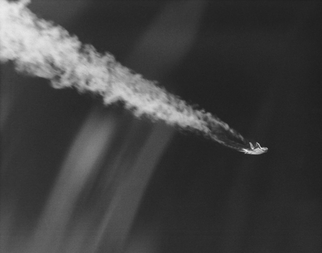
The HL-10 Lifting Body is seen here in powered flight shortly after launch from the B-52 mothership. When HL-10 powered flights began on October 23, 1968, the vehicle used the same basic XLR-11 rocket engine that powered the original X-1s. A total of five powered flights were made before the HL-10 first flew supersonically on May 9, 1969, with John Manke in the pilot's seat.
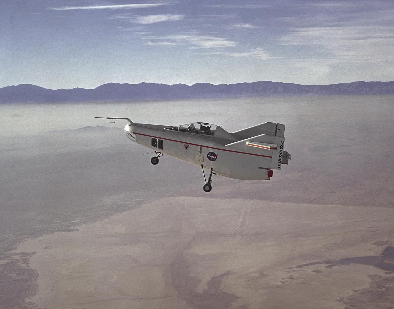
The M2-F1 Lifting Body is seen here under tow, high above Rogers Dry Lake near the Flight Research Center (later redesignated the Dryden Flight Research Center), Edwards, California. R. Dale Reed effectively advocated the project with the support of NASA research pilot Milt Thompson. Together, they gained the support of Flight Research Center Director Paul Bikle. After a six-month feasibility study, Bikle gave approval in the fall of 1962 for the M2-F1 to be built.
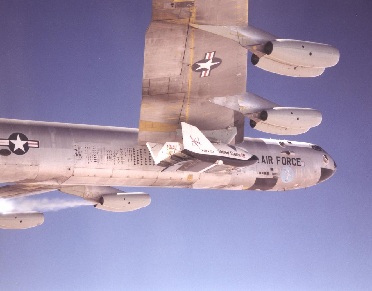
This photo shows one of the X-38 lifting-body research vehicles mated to NASA's B-52 mothership in flight prior to launch. The B-52 has been a workhorse for the Dryden Flight Research Center for more than 40 years, carrying numerous research vehicles aloft and conducting a variety of other research flight experiments.
The M2-F3 Lifting Body is seen here on the lakebed next to the NASA Flight Research Center (FRC--later Dryden Flight Research Center), Edwards, California. The May 1967 crash of the M2-F2 had torn off the left fin and landing gear. It had also damaged the external skin and internal structure. Flight Research Center engineers worked with Ames Research Center and the Air Force in redesigning the vehicle with a center fin to provide greater stability. Then Northrop Corporation cooperated with the FRC in rebuilding the vehicle. The entire process took three years.
The M2-F3 Lifting Body is seen here on the lakebed next to the NASA Flight Research Center (later the Dryden Flight Research Center), Edwards, California. Redesigned and rebuilt from the M2-F2, the M2-F3 featured as its most visible change a center fin for greater stability. While the M2-F3 was still demanding to fly, the center fin eliminated the high risk of pilot induced oscillation (PIO) that was characteristic of the M2-F2.
After the grounding of the M2-F1 in 1966, it was kept in outside storage on the Dryden complex. After several years, its fabric and plywood structure was damaged by the sun and weather. Restoration of the vehicle began in February 1994 under the leadership of NASA retiree Dick Fischer, with other retirees who had originally worked on the M2-F1's construction and flight research three decades before also participating. The photo shows the now-restored M2-F1 returning to the site of its flight research, now called the Dryden Flight Research Center, on 22 August 1997.
NASA Flight Research Pilot Milt Thompson, shown here on the lakebed with the M2-F1 lifting body, was an early backer of R. Dale Reed's lifting-body proposal. He urged Flight Research Center director Paul Bikle to approve the M2-F1's construction. Thompson also made the first glide flights in both the M2-F1 and its successor, the heavyweight M2-F2.
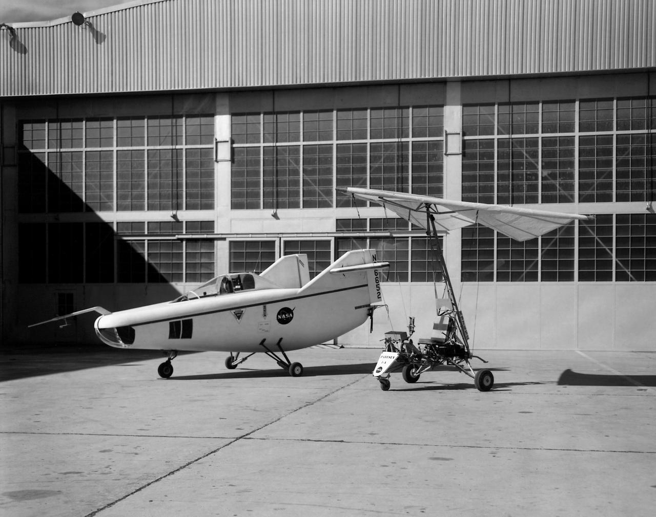
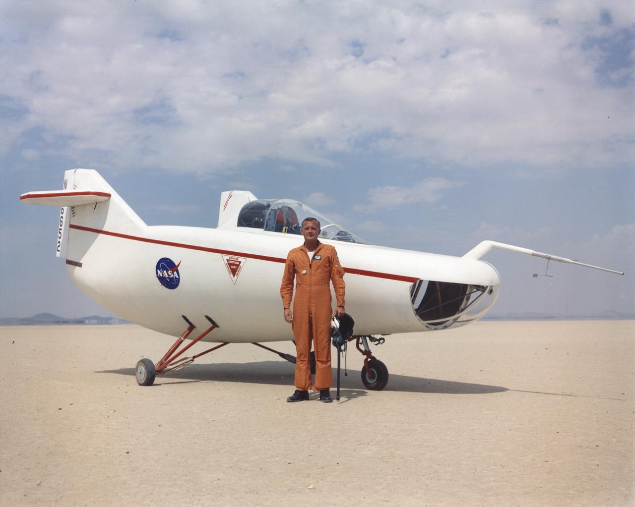
In this photo of the M2-F1 lifting body and the Paresev 1B on the ramp, the viewer sees two vehicles representing different approaches to building a research craft to simulate a spacecraft able to land on the ground instead of splashing down in the ocean as the Mercury capsules did. The M2-F1 was a lifting body, a shape able to re-enter from orbit and land. The Paresev (Paraglider Research Vehicle) used a Rogallo wing that could be (but never was) used to replace a conventional parachute for landing a capsule-type spacecraft, allowing it to make a controlled landing on the ground.
KENNEDY SPACE CENTER, FLA. - In the Orbiter Processing Facility, workers on the floor prepare to attach a crane to the body flap for the orbiter Atlantis. The crane will lift the body flap for installation on the orbiter. The body flap is an aluminum structure consisting of ribs, spars, skin panels and a trailing edge assembly. It thermally shields the three Space Shuttle Main Engines during entry and provides the orbiter with pitch control trim during its atmospheric flight after entry. Atlantis is being processed for its mission, designated STS-121, this summer to the International Space Station. The launch planning window is July 12 - August 3.
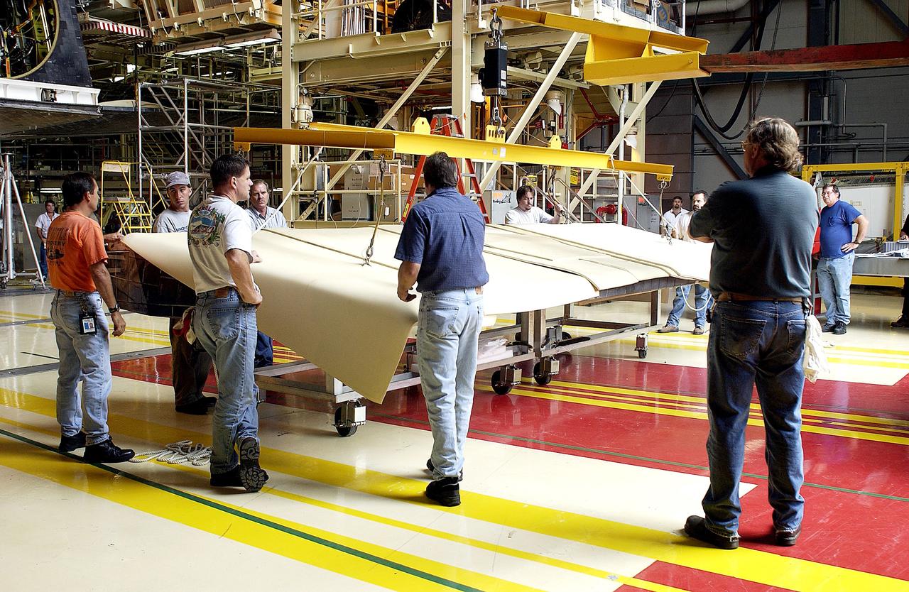
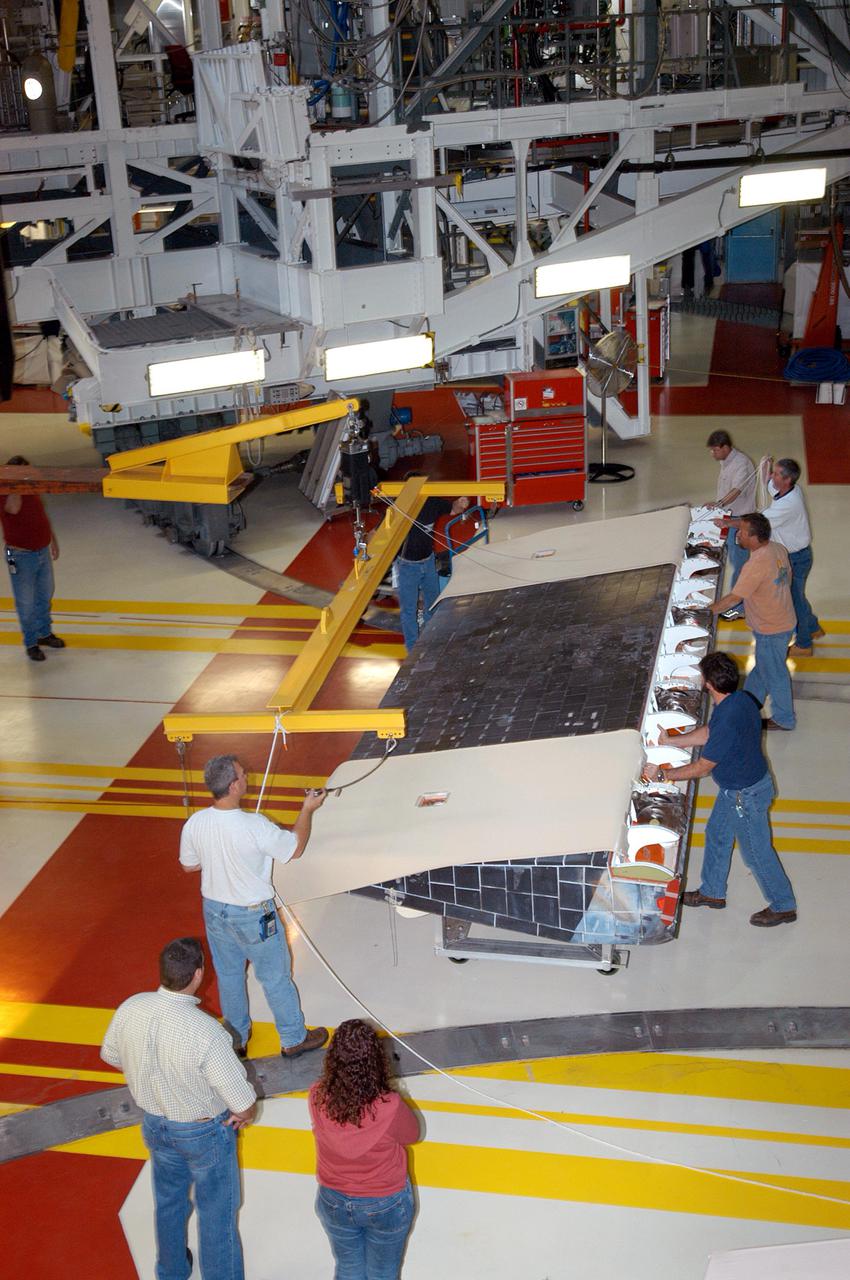
KENNEDY SPACE CENTER, FLA. - Workers in the Orbiter Processing Facility help prepare the body flap for lifting prior to installation on the orbiter Discovery. The body flap is an aluminum structure consisting of ribs, spars, skin panels and a trailing edge assembly. It thermally shields the three main engines during entry and provides pitch control trim during landing approach. Discovery is being processed for launch on the first Return to Flight mission, STS-114.
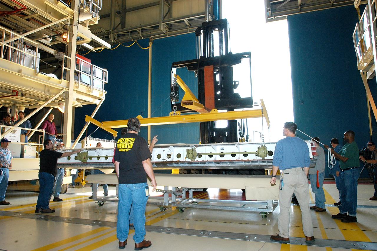
KENNEDY SPACE CENTER, FLA. - A Hyster forklift in the Orbiter Processing Facility lifts the body flap to be installed on the orbiter Discovery. The body flap is an aluminum structure consisting of ribs, spars, skin panels and a trailing edge assembly. It thermally shields the three main engines during entry and provides pitch control trim during landing approach. Discovery is being processed for launch on the first Return to Flight mission, STS-114.
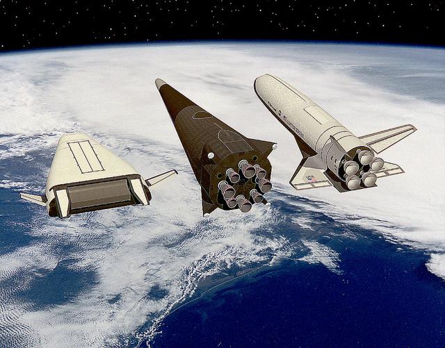
Artist John Frassanito's concept of three Single-Stage-to-Orbit (SSTO) Reusable Launch Vehicles (RLV's). Depicted from the left are: The Lockheed-Martin lifting body configuration that uses an integrated linear aerospike main engine; the McDornell Douglas vertical landing configuration; and the Rockwell wing body configuration that uses liquid oxygen and hydrogen bell engines.
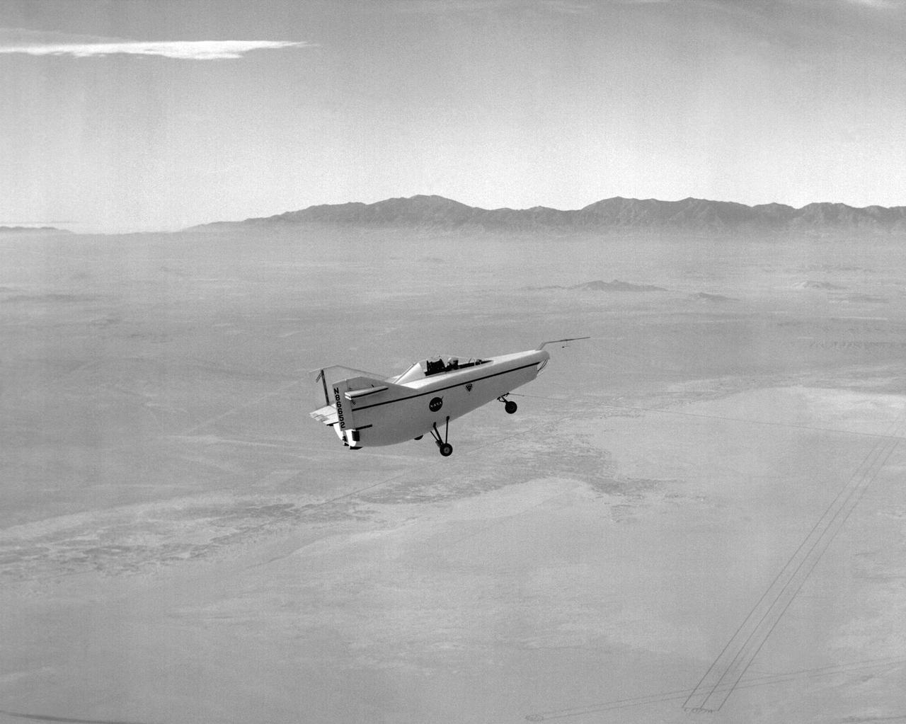
The Hyper III was a low-cost test vehicle for an advanced lifting-body shape. Like the earlier M2-F1, it was a "homebuilt" research aircraft, i.e., built at the Flight Research Center (FRC), later redesignated the Dryden Flight Research Center. It had a steel-tube frame covered with Dacron, a fiberglass nose, sheet aluminum fins, and a wing from an HP-11 sailplane. Construction was by volunteers at the FRC. Although the Hyper III was to be flown remotely in its initial tests, it was fitted with a cockpit for a pilot. On the Hyper III's only flight, it was towed aloft attached to a Navy SH-3 helicopter by a 400-foot cable. NASA research pilot Bruce Peterson flew the SH-3. After he released the Hyper III from the cable, NASA research pilot Milt Thompson flew the vehicle by radio control until the final approach when Dick Fischer took over control using a model-airplane radio-control box. The Hyper III flared, then landed and slid to a stop on Rogers Dry Lakebed.
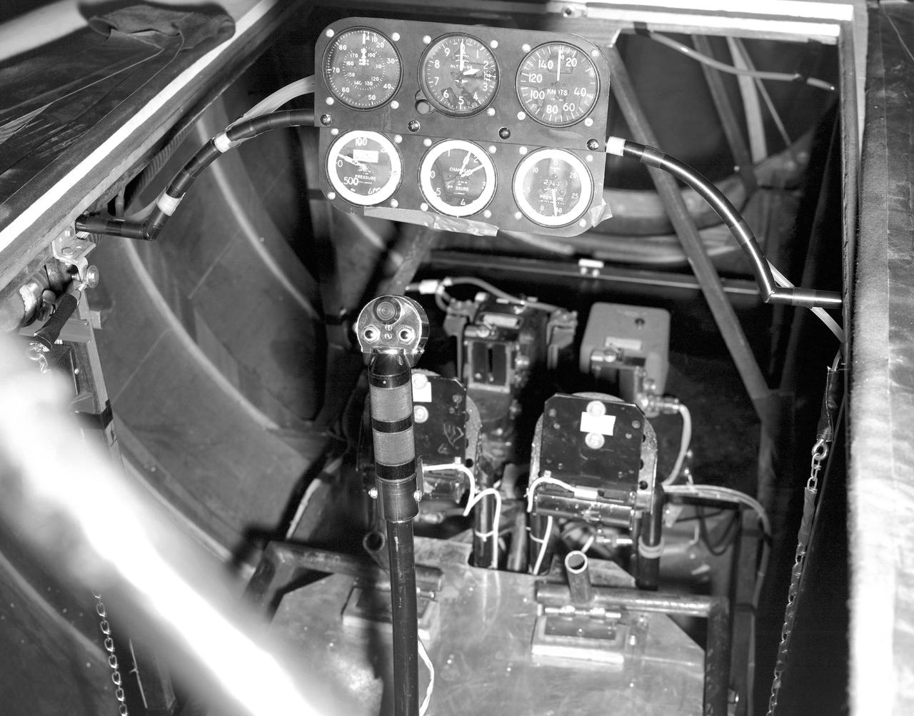
This photo shows the cockpit configuration of the M2-F1 wingless lifting body. With a top speed of about 120 knots, the M2-F1 had a simple instrument panel. Besides the panel itself, the ribs of the wooden shell (left) and the control stick (center) are also visible.
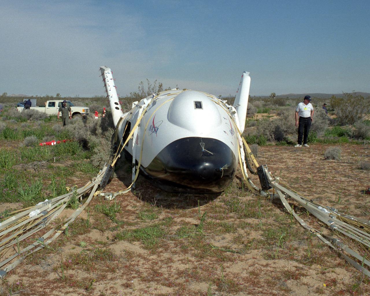
Crew members surround the X-38 lifting body research vehicle after a successful test flight and landing in March 1998. The flight was the first free flight for the vehicle and took place at the Dryden Flight Research Center, Edwards, California.
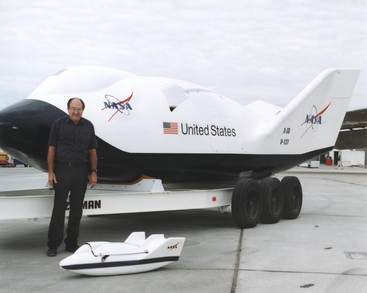
Dale Reed, a NASA engineer who worked on the original lifting-body research programs in the 1960s and 1970s, stands with a scale-model X-38 that was used in 1995 research flights, with a full-scale X-38 (80 percent of the size of a potential Crew Return Vehicle) behind him.
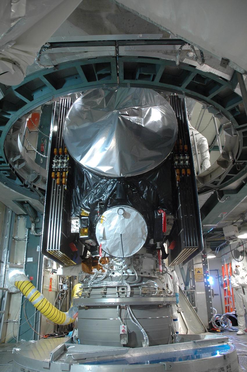
KENNEDY SPACE CENTER, FLA. -- On Launch Pad 17-B at Cape Canaveral Air Force Station, the Dawn spacecraft is lifted off its transporter. Dawn will be lifted into the mobile service tower and prepared for mating with the awaiting Delta II rocket.Dawn is scheduled for launch in a window from 7:25 to 7:54 a.m. Sept. 26 from CCAFS. During its nearly decade-long mission, the Dawn mission will study the asteroid Vesta and dwarf planet Ceres, celestial bodies believed to have accreted early in the history of the solar system. To carry out its scientific mission, the Dawn spacecraft will carry a visible camera, a visible and infrared mapping spectrometer, and a gamma ray and neutron spectrometer, whose data will be used in combination to characterize these bodies. In addition to the three instruments, radiometric and optical navigation data will provide data relating to the gravity field and thus bulk properties and internal structure of the two bodies. Data returned from the Dawn spacecraft could provide opportunities for significant breakthroughs in our knowledge of how the solar system formed. Photo credit: NASA/Jack Pfaller
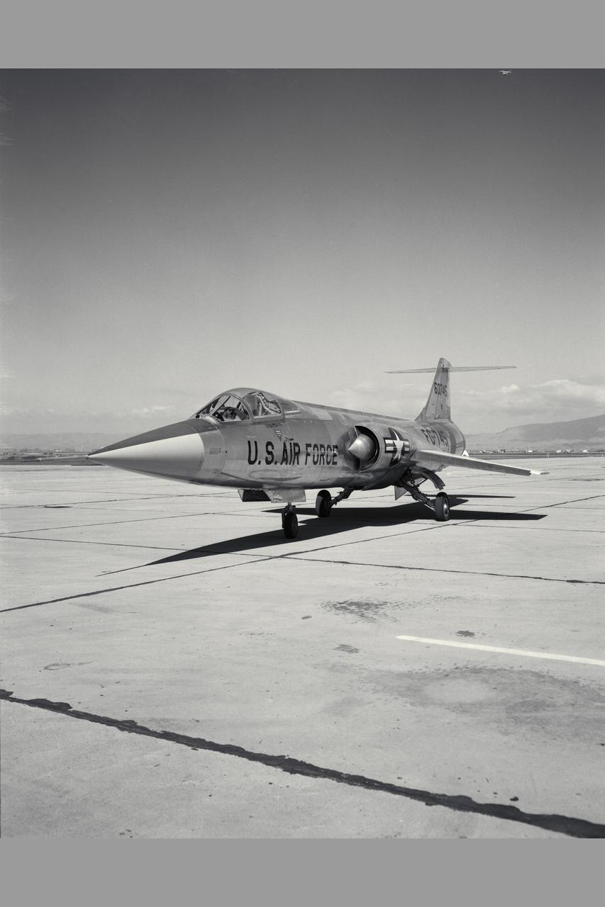
Lockheed JF-104A (AF56-745A Tail No. 60745) Starfighter airplane piloted by Fred Drinkwater conducted flight testing that demonstrated steep approaches that were ultimately used by the space shuttle. Steep descent testing, including power-off landing approaches and demonstration of minimum lift-to-drag ratio (L/D) landings came out of the interest in the use of low L/D lifting bodies for recovery to landing from space. Note: Used in publication in Flight Research at Ames; 57 Years of Development and Validation of Aeronautical Technology NASA SP-1998-3300 fig 93
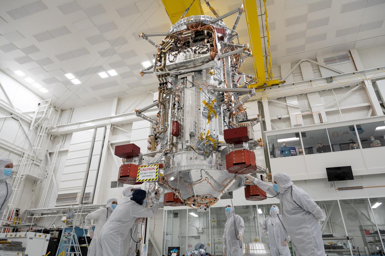
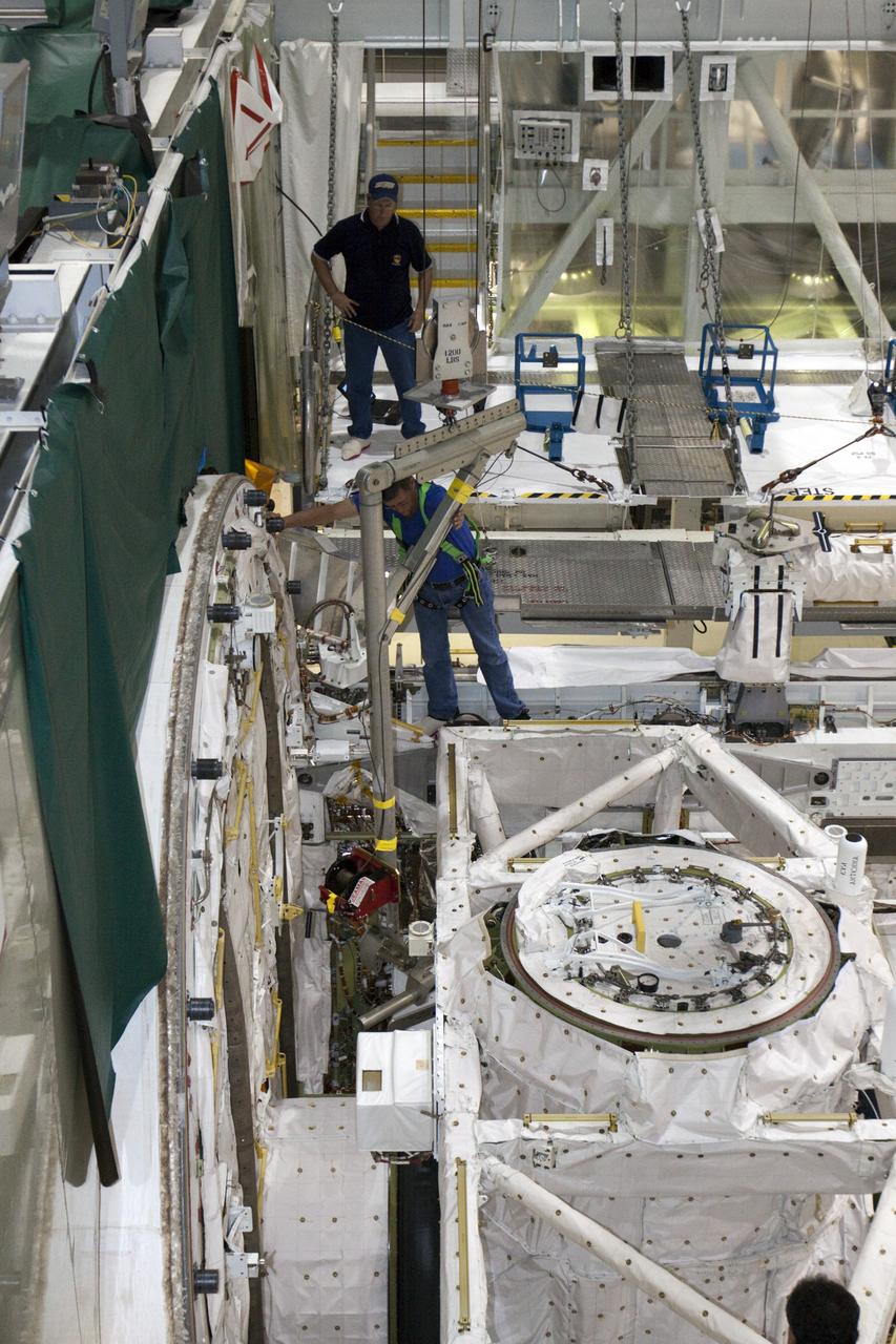
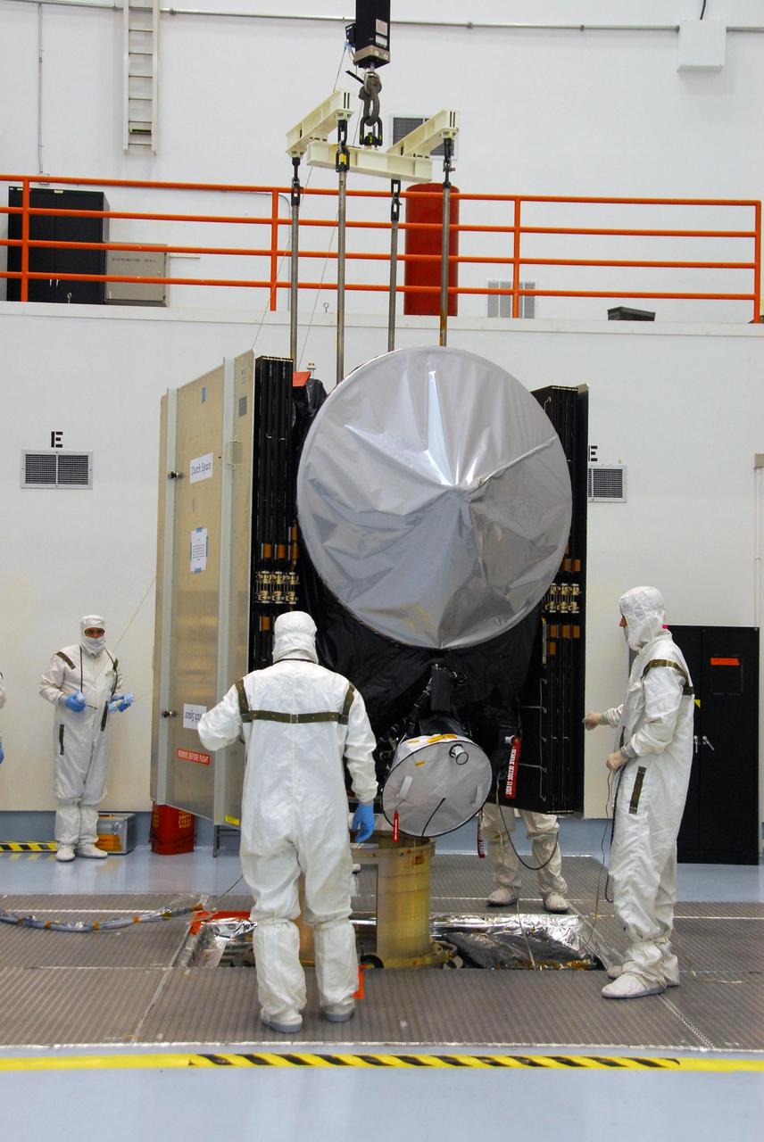
Engineers and technicians use a crane to lift the main body of NASA's Europa Clipper spacecraft and position it in the High Bay 1 clean room of the Spacecraft Assembly Facility at the agency's Jet Propulsion Laboratory in Southern California. Standing 10 feet (3 meters) high and 5 feet (1.5 meters) wide, the core will be the focus of attention as the spacecraft is assembled for its launch to Jupiter's moon Europa in October 2024. Europa Clipper will conduct nearly 50 flybys of the icy Jovian moon Europa, which scientists are confident harbors an internal ocean containing twice as much water as Earth's oceans combined. The moon may currently have conditions suitable for supporting life. The spacecraft's nine science instruments, plus a gravity science investigation, will gather data on the moon's atmosphere, surface, and interior – information that scientists will use to gauge the depth and salinity of the ocean, the thickness of the ice crust, and potential plumes that may be venting subsurface water into space. https://photojournal.jpl.nasa.gov/catalog/PIA25491
Bruce A. Peterson standing beside the M2-F2 lifting body on Rogers Dry Lake. Peterson became the NASA project pilot for the lifting body program after Milt Thompson retired from flying in late 1966. Peterson had flown the M2-F1, and made the first glide flight of the HL-10 heavy-weight lifting body in December 1966. On May 10, 1967, Peterson made his fourth glide flight in the M2-F2. This was also the M2-F2's 16th glide flight, scheduled to be the last one before the powered flights began. However, as pilot Bruce Peterson neared the lakebed, the M2-F2 suffered a pilot induced oscillation (PIO). The vehicle rolled from side to side in flight as he tried to bring it under control. Peterson recovered, but then observed a rescue helicopter that seemed to pose a collision threat. Distracted, Peterson drifted in a cross-wind to an unmarked area of the lakebed where it was very difficult to judge the height over the lakebed because of a lack of the guidance the markers provided on the lakebed runway. Peterson fired the landing rockets to provide additional lift, but he hit the lakebed before the landing gear was fully down and locked. The M2-F2 rolled over six times, coming to rest upside down. Pulled from the vehicle by Jay King and Joseph Huxman, Peterson was rushed to the base hospital, transferred to March Air Force Base and then the UCLA Hospital. He recovered but lost vision in his right eye due to a staph infection.

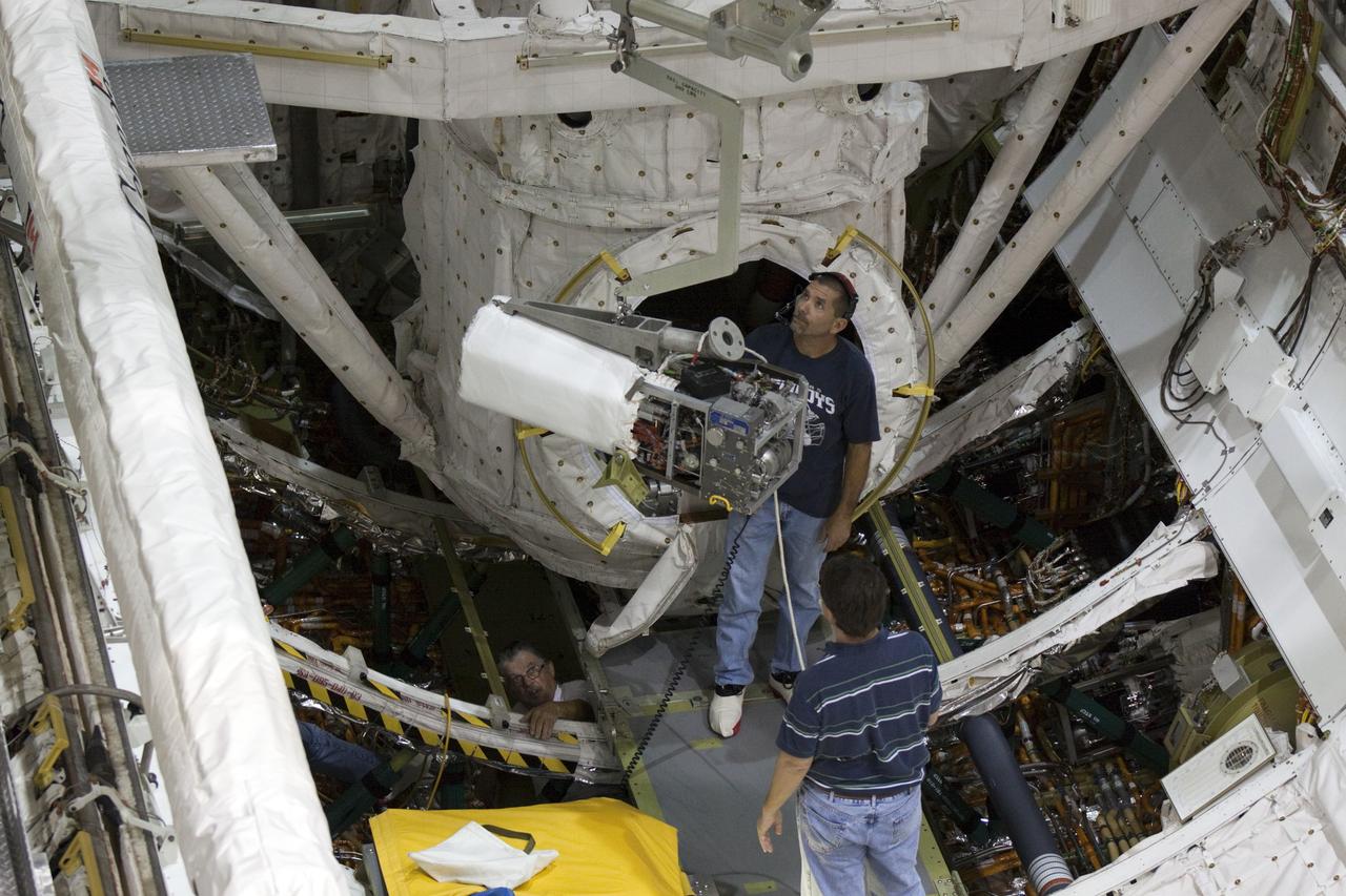
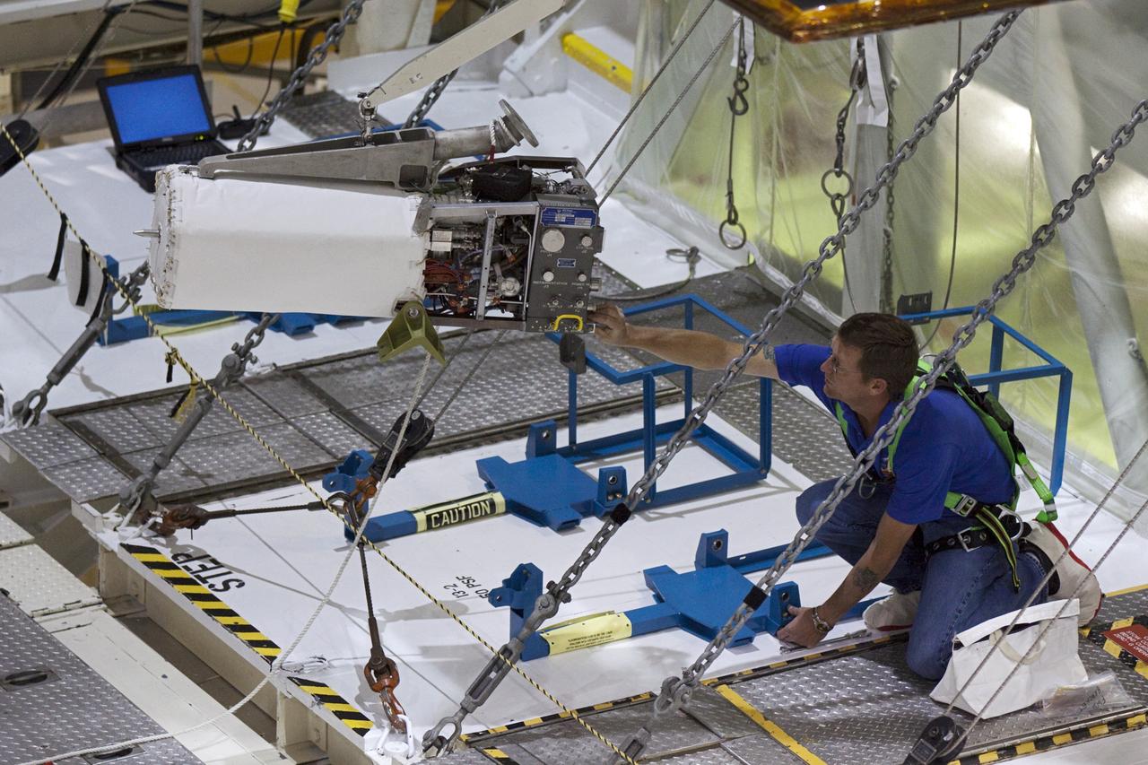
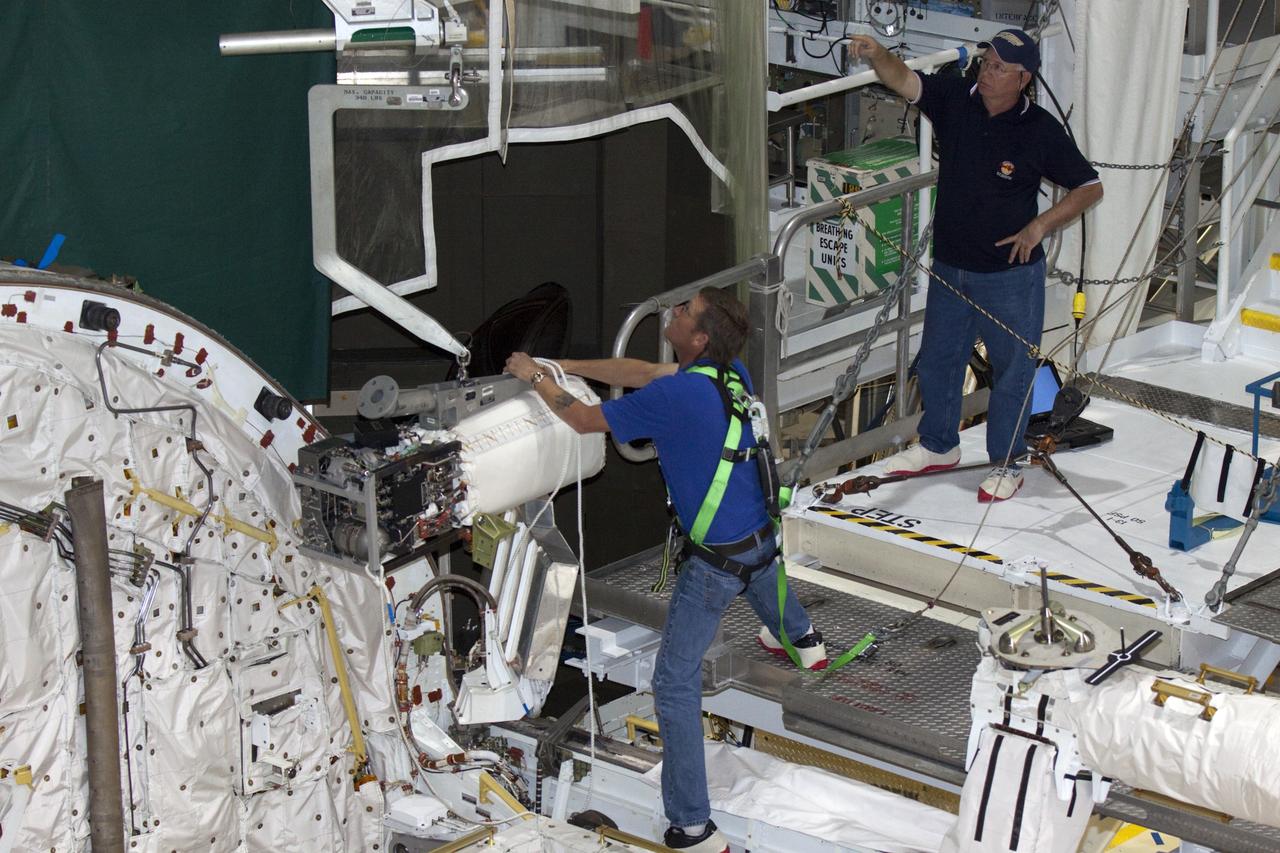
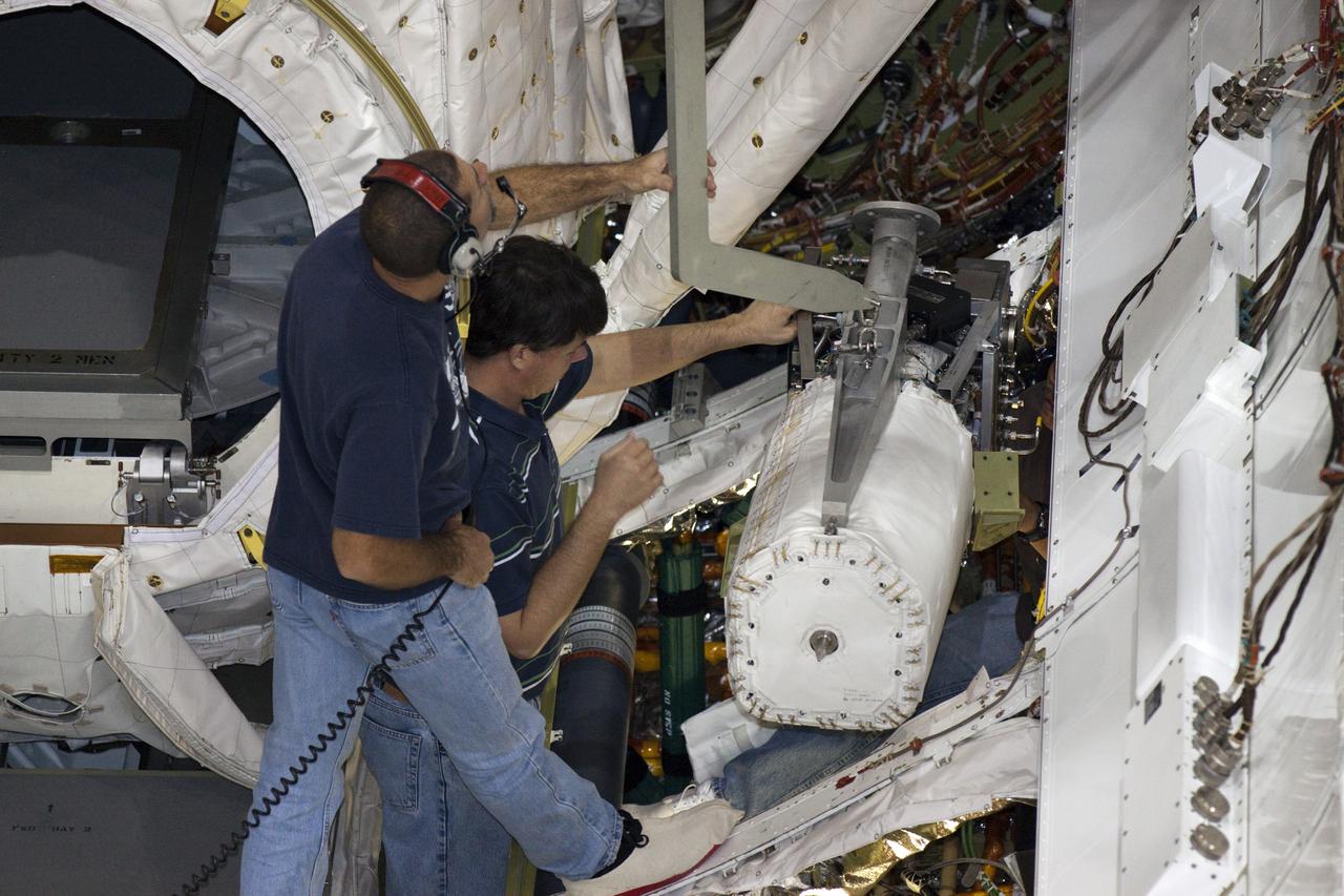
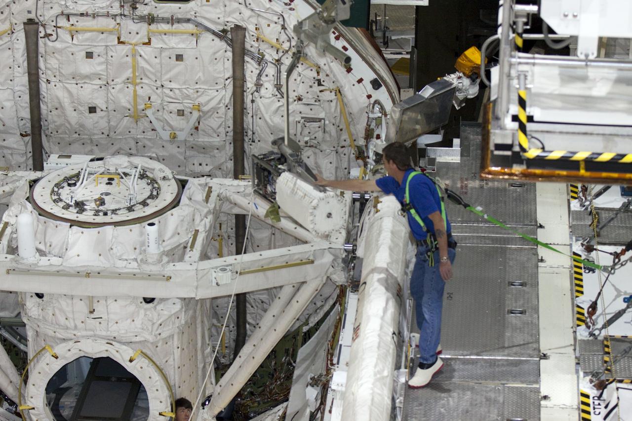
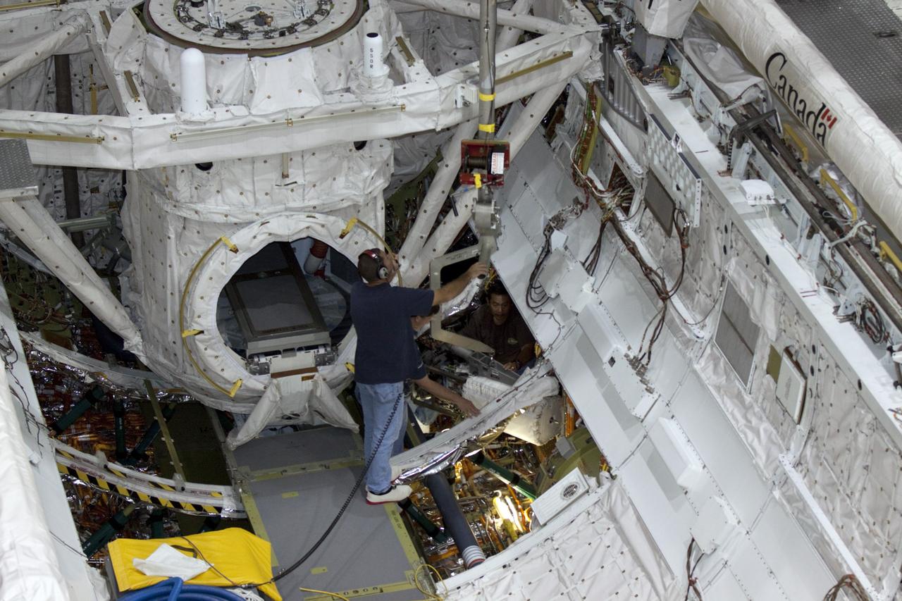
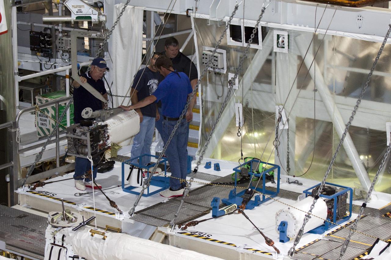
KENNEDY SPACE CENTER, FLA. -- At Launch Pad 39A, workers move the replacement Power Drive Unit (PDU) into the body of Space Shuttle Atlantis. The PDU controls the rudder/speed brake on the orbiter. Atlantis is scheduled to lift off April 24 at 4:15 p.m. EDT on mission STS-101, the third flight to the International Space Station. The primary mission is to carry logistics and supplies to the Space Station, plus the crew will be preparing the Station for the arrival of the Zvezda Service Module, expected to be launched by Russia in July 2000
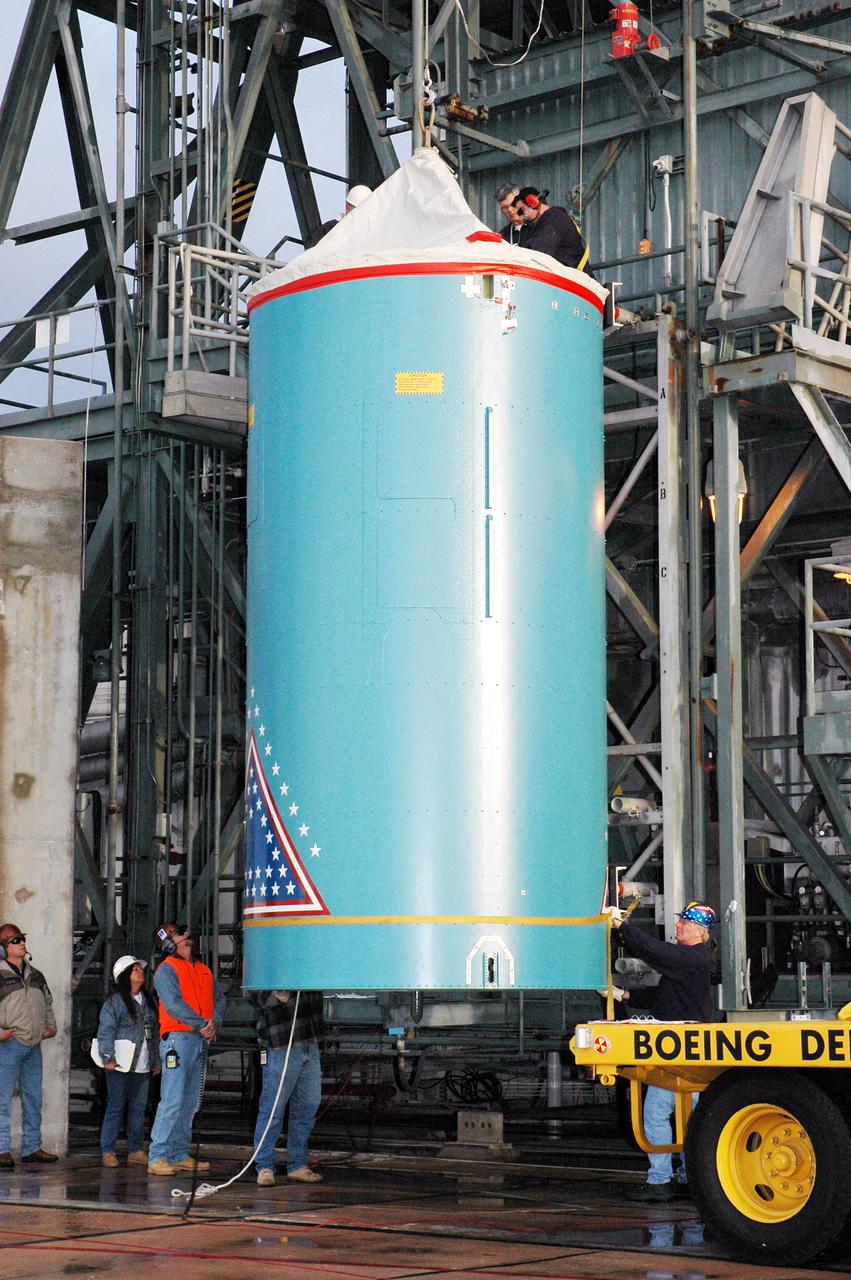
KENNEDY SPACE CENTER, FLA. - In the mobile service tower on Pad 17-B, Cape Canaveral Air Force Station , Fla., the Boeing Delta II interstage adapter is lifted away from the center body section. The interstage adapter was found to be faulty during a review of launch vehicle hardware. It will be replaced, and the second stage previously removed will be re-installed within a few days. Launch of Deep Impact is now scheduled no earlier than Jan. 12.
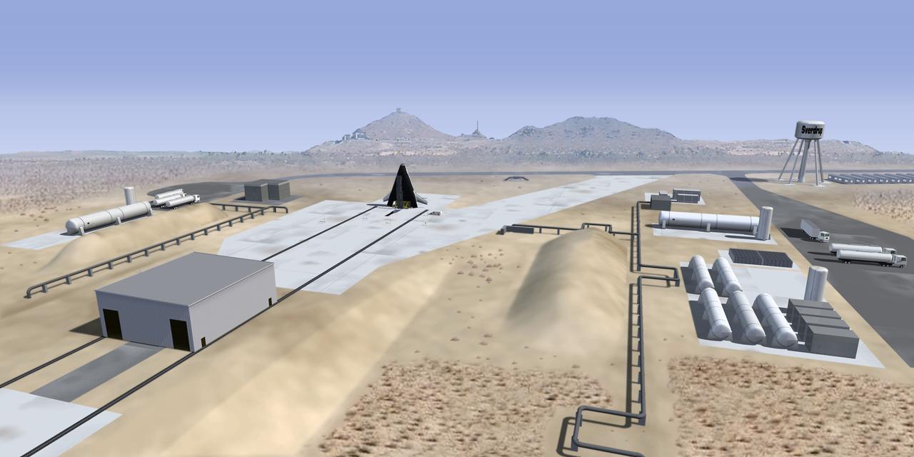
This is an artist's interpretation of a future launch complex for third generation propulsion reusable launch vehicles such as the X-33. The X-33 is a sub-scale technology demonstrator prototype of a Reusable Launch Vehicle (RLV), with a vertical take off / horizontal landing (lifting body) concept, which was manufactured and named as the Venture Star by Lockheed Martin. The X-33 program was cancelled in 2001.
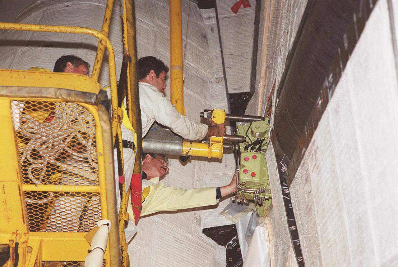
KENNEDY SPACE CENTER, FLA. -- At Launch Pad 39A, workers move the replacement Power Drive Unit (PDU) into the body of Space Shuttle Atlantis. The PDU controls the rudder/speed brake on the orbiter. Atlantis is scheduled to lift off April 24 at 4:15 p.m. EDT on mission STS-101, the third flight to the International Space Station. The primary mission is to carry logistics and supplies to the Space Station, plus the crew will be preparing the Station for the arrival of the Zvezda Service Module, expected to be launched by Russia in July 2000
KENNEDY SPACE CENTER, FLA. - In the mobile service tower on Pad 17-B, Cape Canaveral Air Force Station , Fla., the Boeing Delta II interstage adapter is being lifted away from the center body section. The interstage adapter was found to be faulty during a review of launch vehicle hardware. It will be replaced, and the second stage previously removed will be re-installed within a few days. Launch of Deep Impact is now scheduled no earlier than Jan. 12.
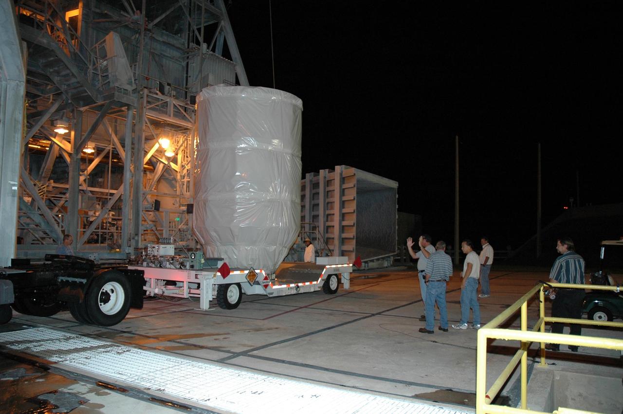
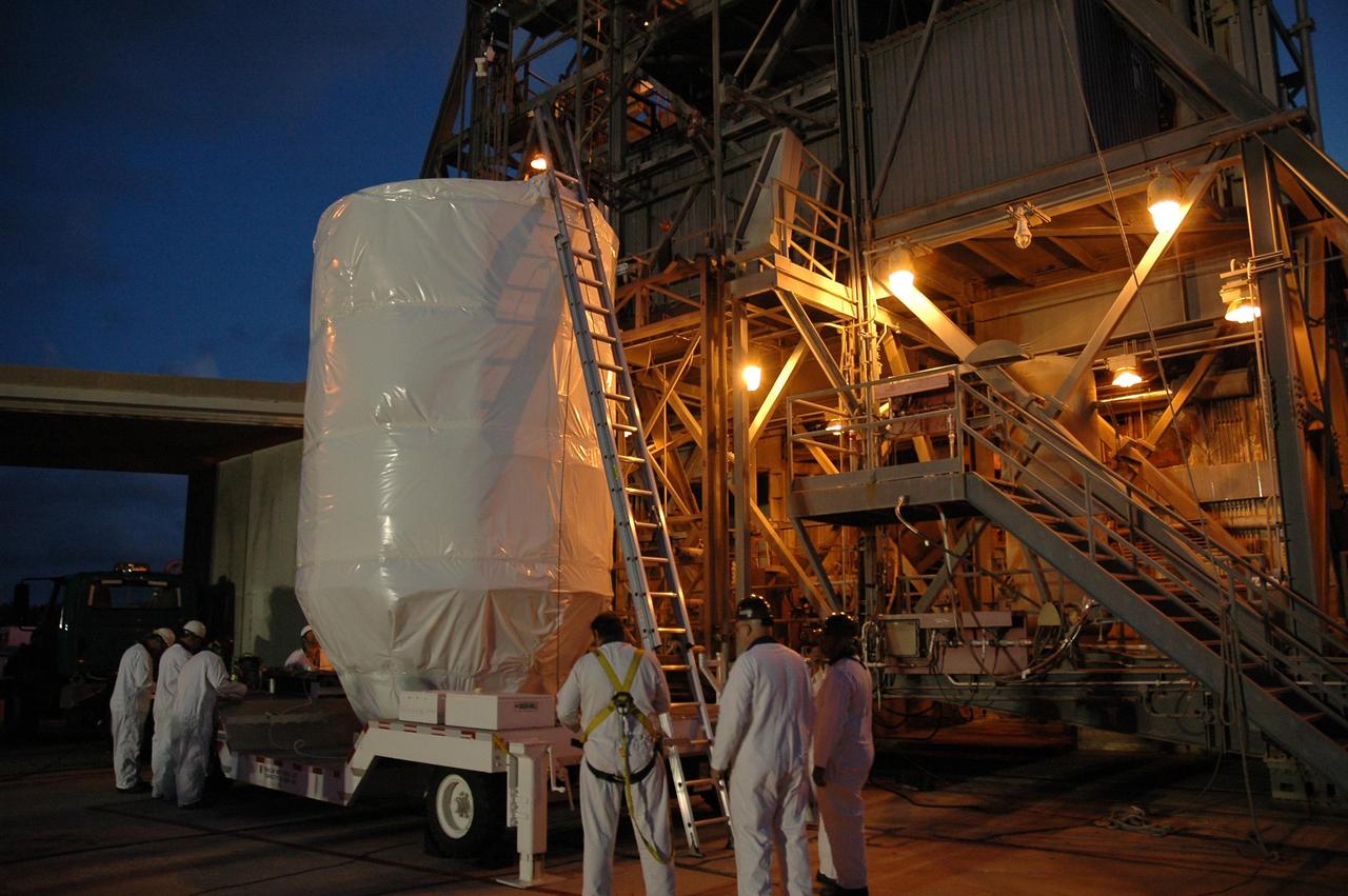
KENNEDY SPACE CENTER, FLA. -- The Dawn spacecraft arrives on Launch Pad 17-B at Cape Canaveral Air Force Station. At the pad, Dawn will be lifted into the mobile service tower and prepared for mating with the awaiting Delta II rocket. Dawn is scheduled for launch in a window from 7:25 to 7:54 a.m. Sept. 26 from CCAFS. During its nearly decade-long mission, the Dawn mission will study the asteroid Vesta and dwarf planet Ceres, celestial bodies believed to have accreted early in the history of the solar system. To carry out its scientific mission, the Dawn spacecraft will carry a visible camera, a visible and infrared mapping spectrometer, and a gamma ray and neutron spectrometer, whose data will be used in combination to characterize these bodies. In addition to the three instruments, radiometric and optical navigation data will provide data relating to the gravity field and thus bulk properties and internal structure of the two bodies. Data returned from the Dawn spacecraft could provide opportunities for significant breakthroughs in our knowledge of how the solar system formed. Photo credit: NASA/Jack Pfaller
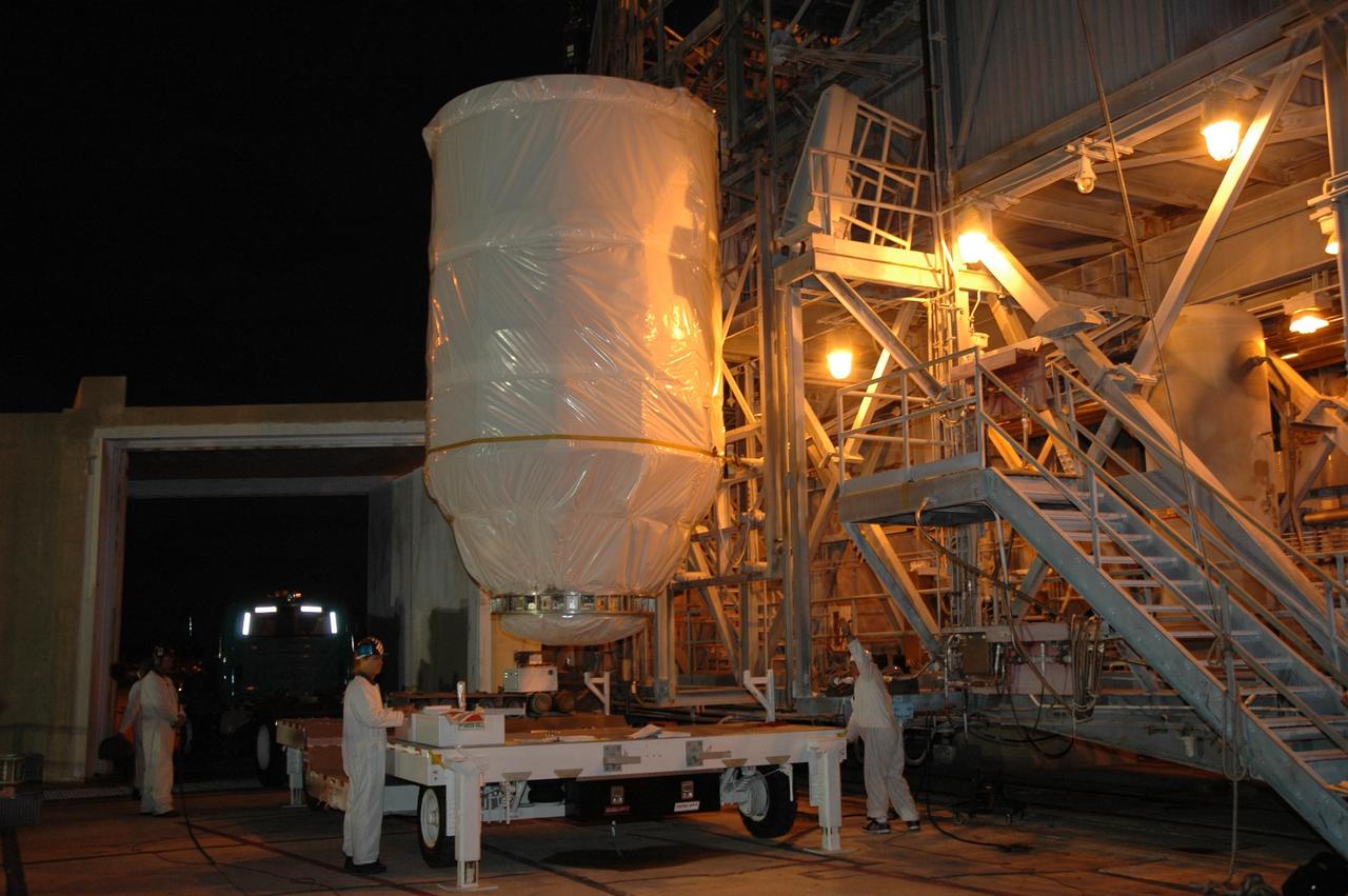
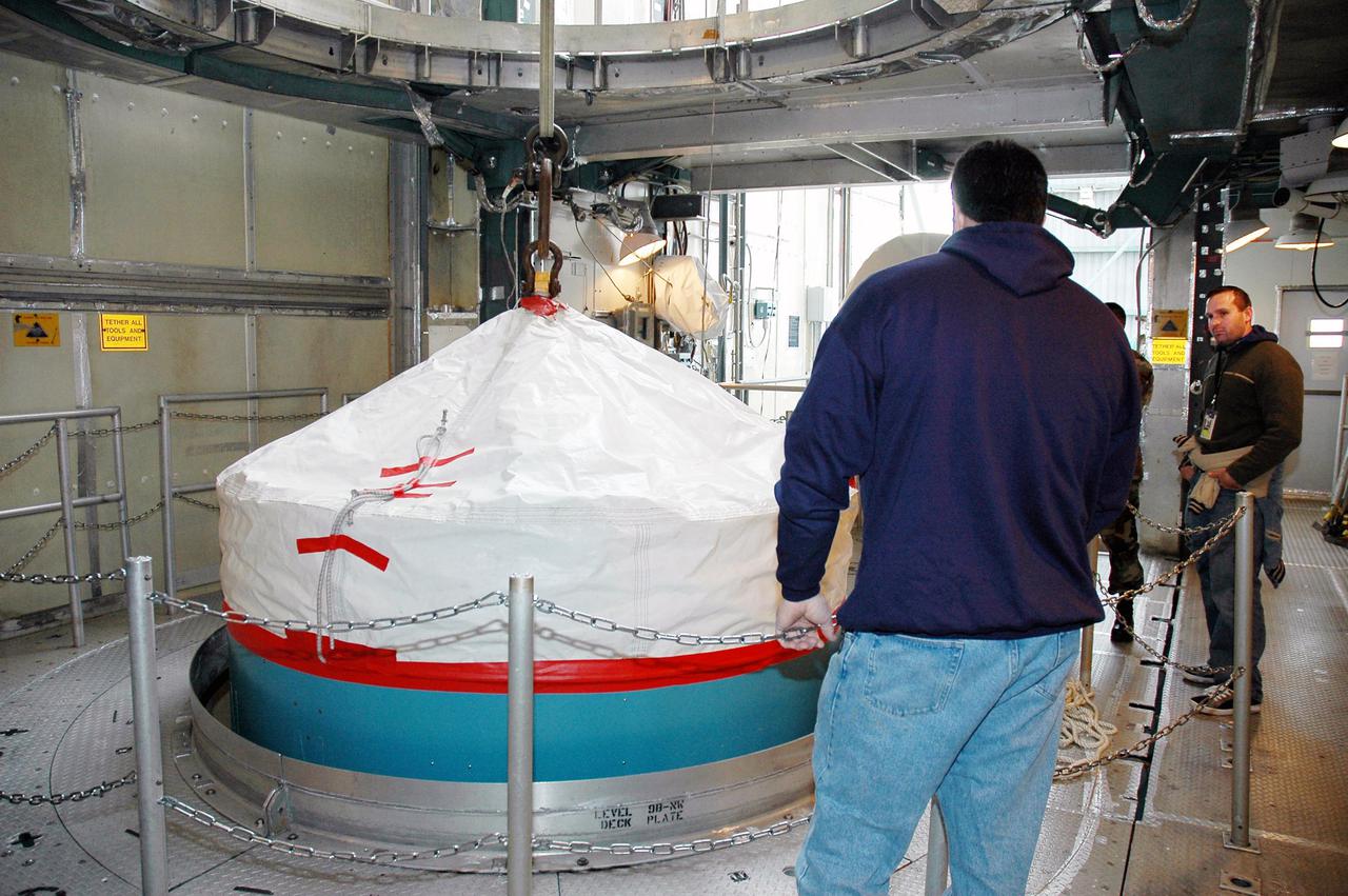
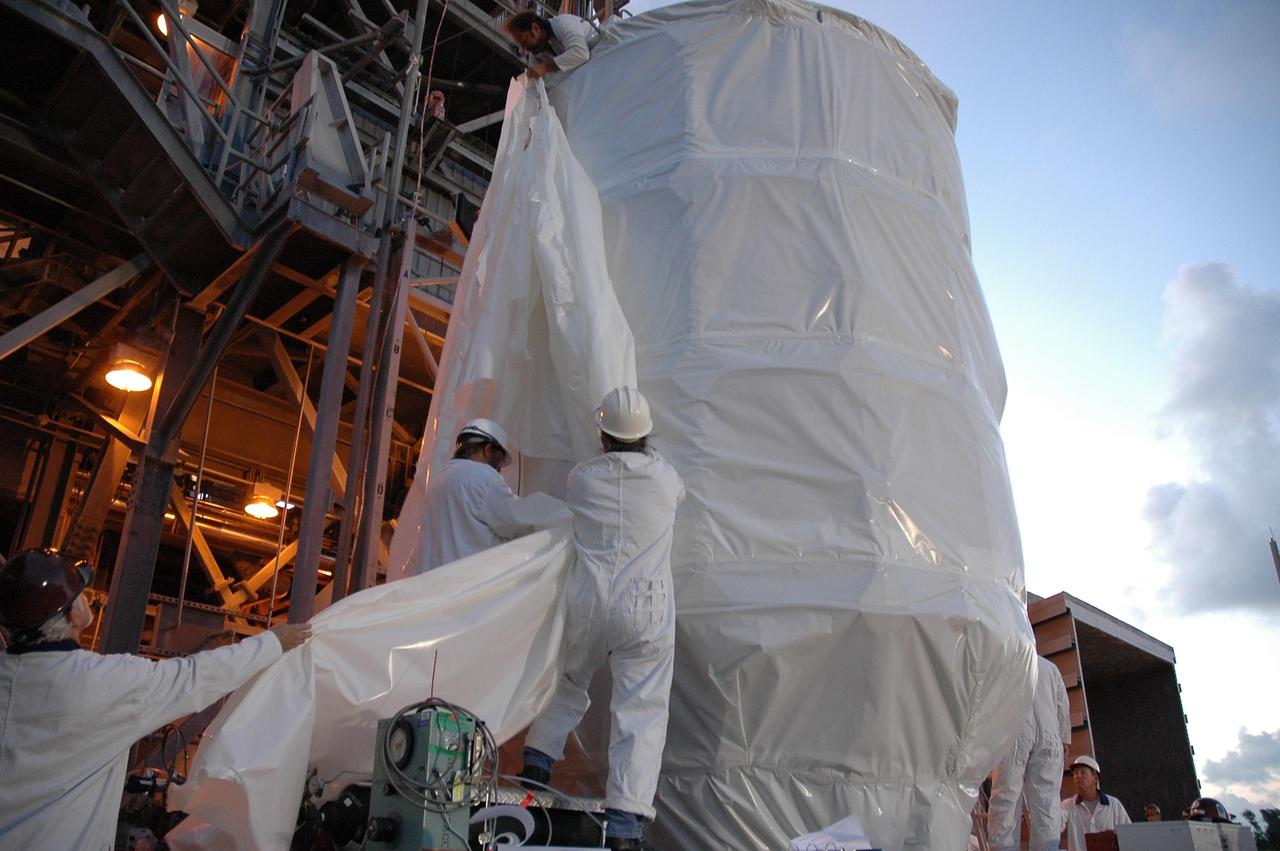
KENNEDY SPACE CENTER, FLA. -- In the mobile service tower on Launch Pad 17-B at Cape Canaveral Air Force Station, the upper transportation canister is lifted away from the Dawn spacecraft. After removal of the canister, Dawn will be mated with the waiting Delta II rocket. Dawn is scheduled for launch in a window from 7:25 to 7:54 a.m. EDT Sept. 26 from CCAFS. During its nearly decade-long mission, the Dawn mission will study the asteroid Vesta and dwarf planet Ceres, celestial bodies believed to have accreted early in the history of the solar system. To carry out its scientific mission, the Dawn spacecraft will carry a visible camera, a visible and infrared mapping spectrometer, and a gamma ray and neutron spectrometer, whose data will be used in combination to characterize these bodies. In addition to the three instruments, radiometric and optical navigation data will provide data relating to the gravity field and thus bulk properties and internal structure of the two bodies. Data returned from the Dawn spacecraft could provide opportunities for significant breakthroughs in our knowledge of how the solar system formed. Photo credit: NASA/Jim Grossmann
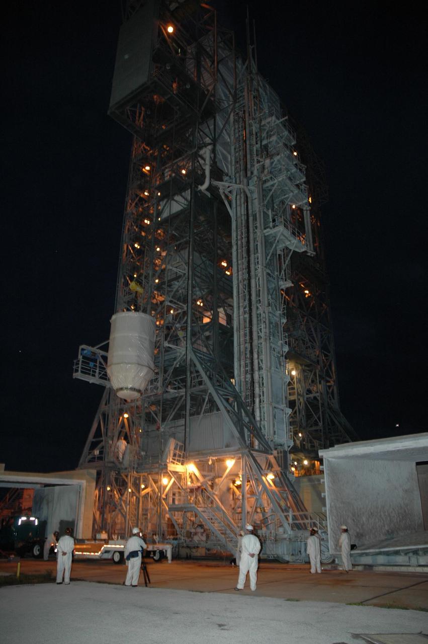
KENNEDY SPACE CENTER, FLA. -- On Launch Pad 17-B at Cape Canaveral Air Force Station, the Dawn spacecraft is lifted alongside the mobile service tower. At the top, Dawn will be prepared for mating with the awaiting Delta II rocket. Dawn is scheduled for launch in a window from 7:25 to 7:54 a.m. Sept. 26 from CCAFS. During its nearly decade-long mission, the Dawn mission will study the asteroid Vesta and dwarf planet Ceres, celestial bodies believed to have accreted early in the history of the solar system. To carry out its scientific mission, the Dawn spacecraft will carry a visible camera, a visible and infrared mapping spectrometer, and a gamma ray and neutron spectrometer, whose data will be used in combination to characterize these bodies. In addition to the three instruments, radiometric and optical navigation data will provide data relating to the gravity field and thus bulk properties and internal structure of the two bodies. Data returned from the Dawn spacecraft could provide opportunities for significant breakthroughs in our knowledge of how the solar system formed. Photo credit: NASA/Jack Pfaller
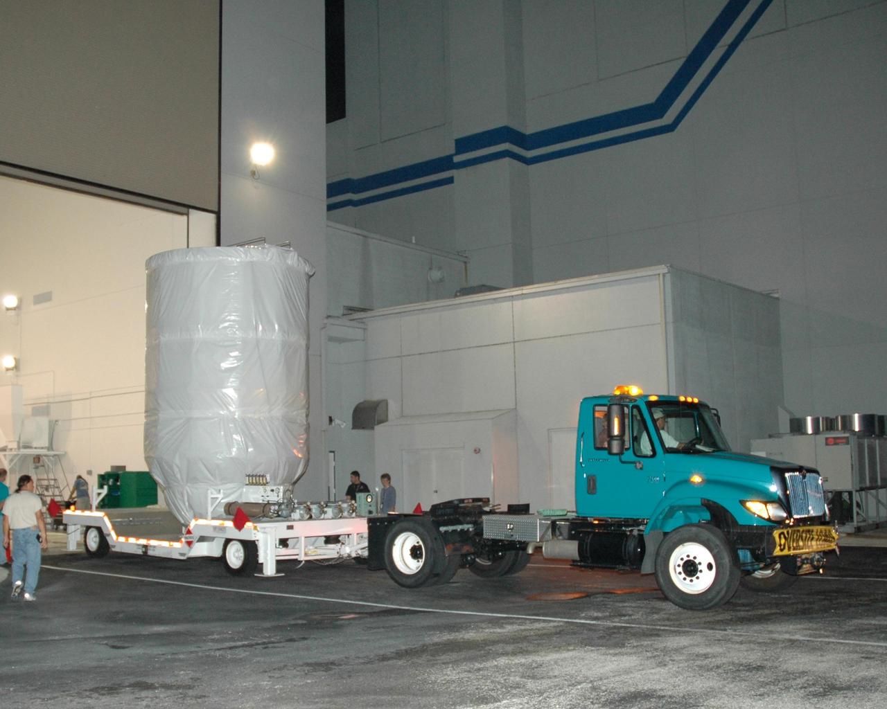
KENNEDY SPACE CENTER, FLA. -- The Dawn spacecraft is moved out of the Astrotech Space Operations facility, on its way to Launch Pad 17-B at Cape Canaveral Air Force Station. At the pad, Dawn will be lifted into the mobile service tower and prepared for mating with the awaiting Delta II rocket. Dawn is scheduled for launch in a window from 7:25 to 7:54 a.m. Sept. 26 from CCAFS. During its nearly decade-long mission, the Dawn mission will study the asteroid Vesta and dwarf planet Ceres, celestial bodies believed to have accreted early in the history of the solar system. To carry out its scientific mission, the Dawn spacecraft will carry a visible camera, a visible and infrared mapping spectrometer, and a gamma ray and neutron spectrometer, whose data will be used in combination to characterize these bodies. In addition to the three instruments, radiometric and optical navigation data will provide data relating to the gravity field and thus bulk properties and internal structure of the two bodies. Data returned from the Dawn spacecraft could provide opportunities for significant breakthroughs in our knowledge of how the solar system formed. Photo credit: NASA/Jack Pfaller

KENNEDY SPACE CENTER, FLA. -- On Launch Pad 17-B at Cape Canaveral Air Force Station, the Dawn spacecraft is lifted alongside the mobile service tower. At the top, Dawn will be prepared for mating with the awaiting Delta II rocket. Dawn is scheduled for launch in a window from 7:25 to 7:54 a.m. Sept. 26 from CCAFS. During its nearly decade-long mission, the Dawn mission will study the asteroid Vesta and dwarf planet Ceres, celestial bodies believed to have accreted early in the history of the solar system. To carry out its scientific mission, the Dawn spacecraft will carry a visible camera, a visible and infrared mapping spectrometer, and a gamma ray and neutron spectrometer, whose data will be used in combination to characterize these bodies. In addition to the three instruments, radiometric and optical navigation data will provide data relating to the gravity field and thus bulk properties and internal structure of the two bodies. Data returned from the Dawn spacecraft could provide opportunities for significant breakthroughs in our knowledge of how the solar system formed. Photo credit: NASA/Jack Pfaller
KENNEDY SPACE CENTER, FLA. -- At Launch Pad 17-B, at Cape Canaveral Air Force Station, workers attach a crane to NASA's Dawn spacecraft. It will be lifted into the mobile service tower for mating to the Delta II launch vehicle.Launch is scheduled for July 7. Dawn is the ninth mission in NASA's Discovery Program. The spacecraft will be the first to orbit two planetary bodies, asteroid Vesta and dwarf planet Ceres, during a single mission. Vesta and Ceres lie in the asteroid belt between Mars and Jupiter. It is also NASA's first purely scientific mission powered by three solar electric ion propulsion engines. Photo credit: NASA/Troy Cryder.
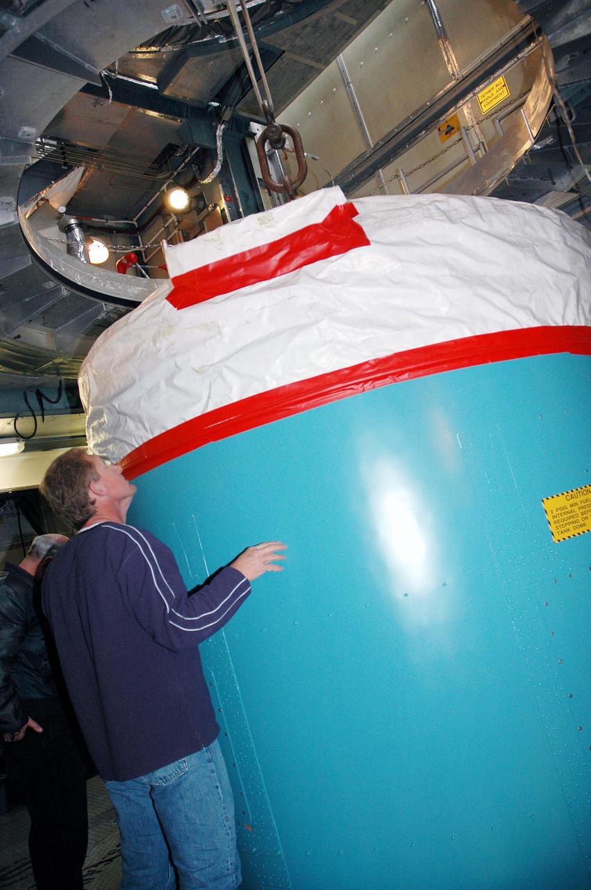
CAPE CANAVERAL, Fla. – Inside Orbiter Processing Facility-2 at NASA’s Kennedy Space Center in Florida, technicians help position a special crane in place to lift one of the three fuel cells away from space shuttle Atlantis’ payload bay. The fuel cells will be drained of all fluids. The hydrogen and oxygen dewars which feed reactants to the fuel cells remain in Atlantis’ mid-body and will be purged with inert gases and vented down. The work is part of the Space Shuttle Program’s transition and retirement processing of shuttle Atlantis. The orbiter is being prepared for display at the Kennedy Space Center Visitor Complex. Photo credit: NASA/Kim Shiflett
CAPE CANAVERAL, Fla. – Inside Orbiter Processing Facility-2 at NASA’s Kennedy Space Center in Florida, technicians monitor the progress as a special crane lifts one of the three fuel cells away from space shuttle Atlantis’ payload bay. The fuel cells will be drained of all fluids. The hydrogen and oxygen dewars which feed reactants to the fuel cells remain in Atlantis’ mid-body and will be purged with inert gases and vented down. The work is part of the Space Shuttle Program’s transition and retirement processing of shuttle Atlantis. The orbiter is being prepared for display at the Kennedy Space Center Visitor Complex. Photo credit: NASA/Kim Shiflett
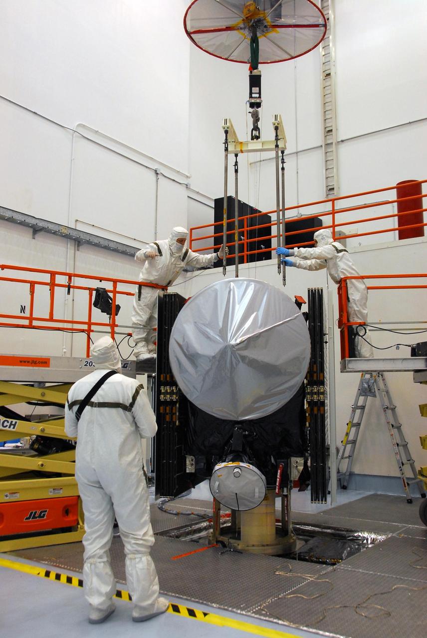
KENNEDY SPACE CENTER, FLA. -- At Astrotech, workers help guide an overhead crane to be attached to the Dawn spacecraft. Dawn will be lifted from its stand, moved and then mated to the upper stage booster for launch. Dawn is scheduled to launch July 7 from Pad 17-B on Cape Canaveral Air Force Station. Dawn's goal is to characterize the conditions and processes of the solar system's earliest epoch by investigating in detail the largest protoplanets that have remained intact since their formations: asteroid Vesta and the dwarf planet Ceres. They reside in the extensive zone between Mars and Jupiter together with many other smaller bodies, called the asteroid belt. Photo credit: NASA/George Shelton
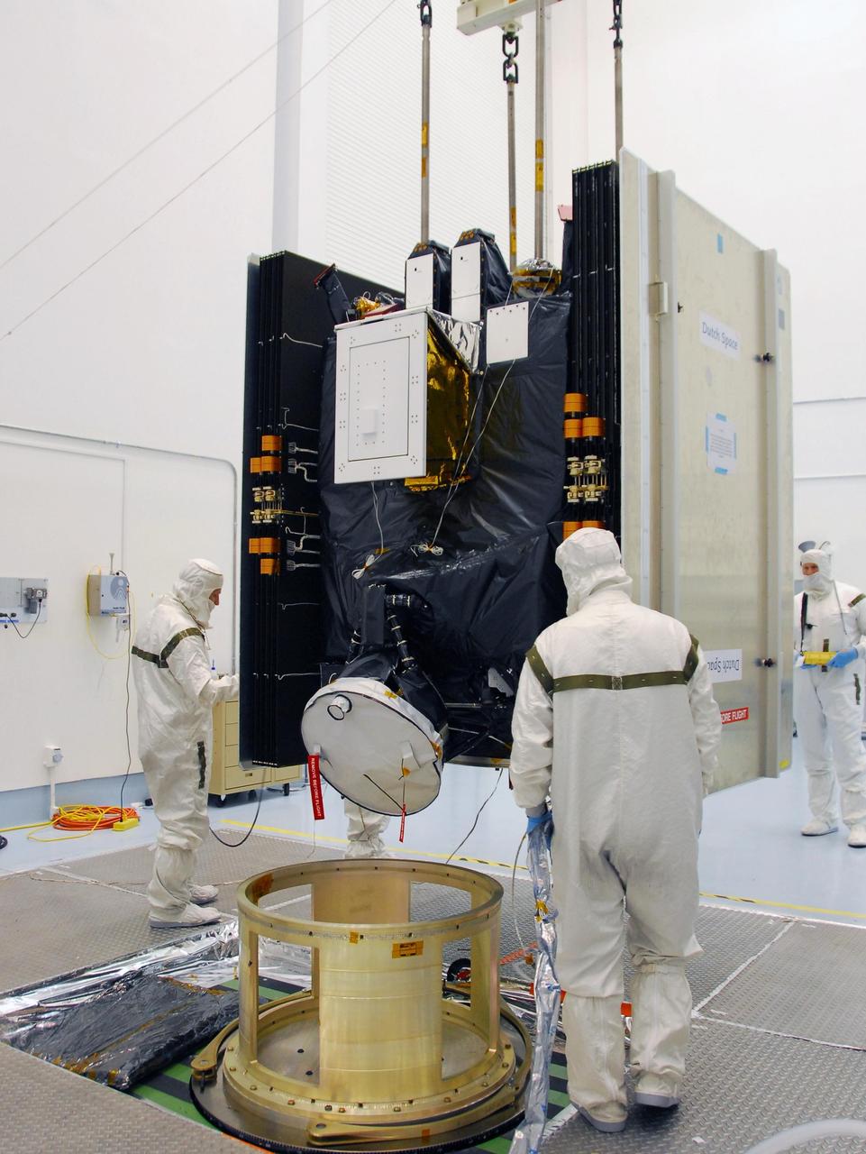
KENNEDY SPACE CENTER, FLA. -- At Astrotech, an overhead crane lifts the Dawn spacecraft from its stand to move it and mate it to the upper stage booster for launch. Dawn is scheduled to launch July 7 from Pad 17-B on Cape Canaveral Air Force Station. Dawn's goal is to characterize the conditions and processes of the solar system's earliest epoch by investigating in detail the largest protoplanets that have remained intact since their formations: asteroid Vesta and the dwarf planet Ceres. They reside in the extensive zone between Mars and Jupiter together with many other smaller bodies, called the asteroid belt. Photo credit: NASA/George Shelton
CAPE CANAVERAL, Fla. – Inside Orbiter Processing Facility-2 at NASA’s Kennedy Space Center in Florida, a technician assists as a special crane lifts one of the three fuel cells away from space shuttle Atlantis’ payload bay. The fuel cells will be drained of all fluids. The hydrogen and oxygen dewars which feed reactants to the fuel cells remain in Atlantis’ mid-body and will be purged with inert gases and vented down. The work is part of the Space Shuttle Program’s transition and retirement processing of shuttle Atlantis. The orbiter is being prepared for display at the Kennedy Space Center Visitor Complex. Photo credit: NASA/Kim Shiflett
KENNEDY SPACE CENTER, FLA. - The replacement interstage adapter for the Boeing Delta II launch vehicle for the Deep Impact spacecraft is ready to be lifted up the mobile service tower on Launch Pad 17-B, Cape Canaveral Air Force Station, Fla. Boeing workers will attach the adapter to the rocket’s center body section. Later the second stage, which was removed to allow access to the previous adapter, will be reattached. The first adapter was removed after it was found to be faulty during a review of launch vehicle hardware. Launch of Deep Impact is now scheduled no earlier than Jan. 12.
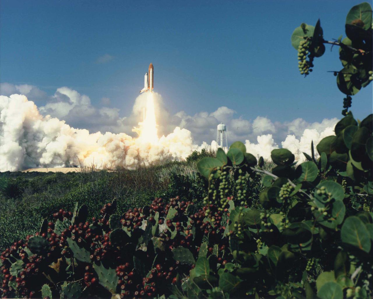
KENNEDY SPACE CENTER, FLA. - The Space Shuttle Columbia climbs a golden tower into a royal blue sky dusted with clouds. The 58th Shuttle flight lifted off from Launch Pad 39B at 10:53:10 a.m. EDT, beginning the longest mission planned in Shuttle program history: two weeks. The Extended Duration Orbiter STS-58 mission will allow the seven-member crew to delve extensively into a number of experiments investigating the adaptation of the human body to space. Spacelab Llife Sciences-2 is the second Spacelab mission dedicated solely to life sciences research.
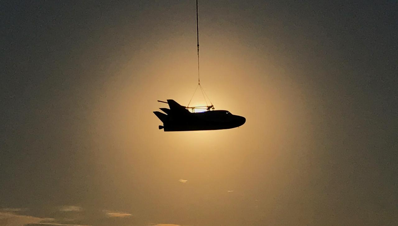
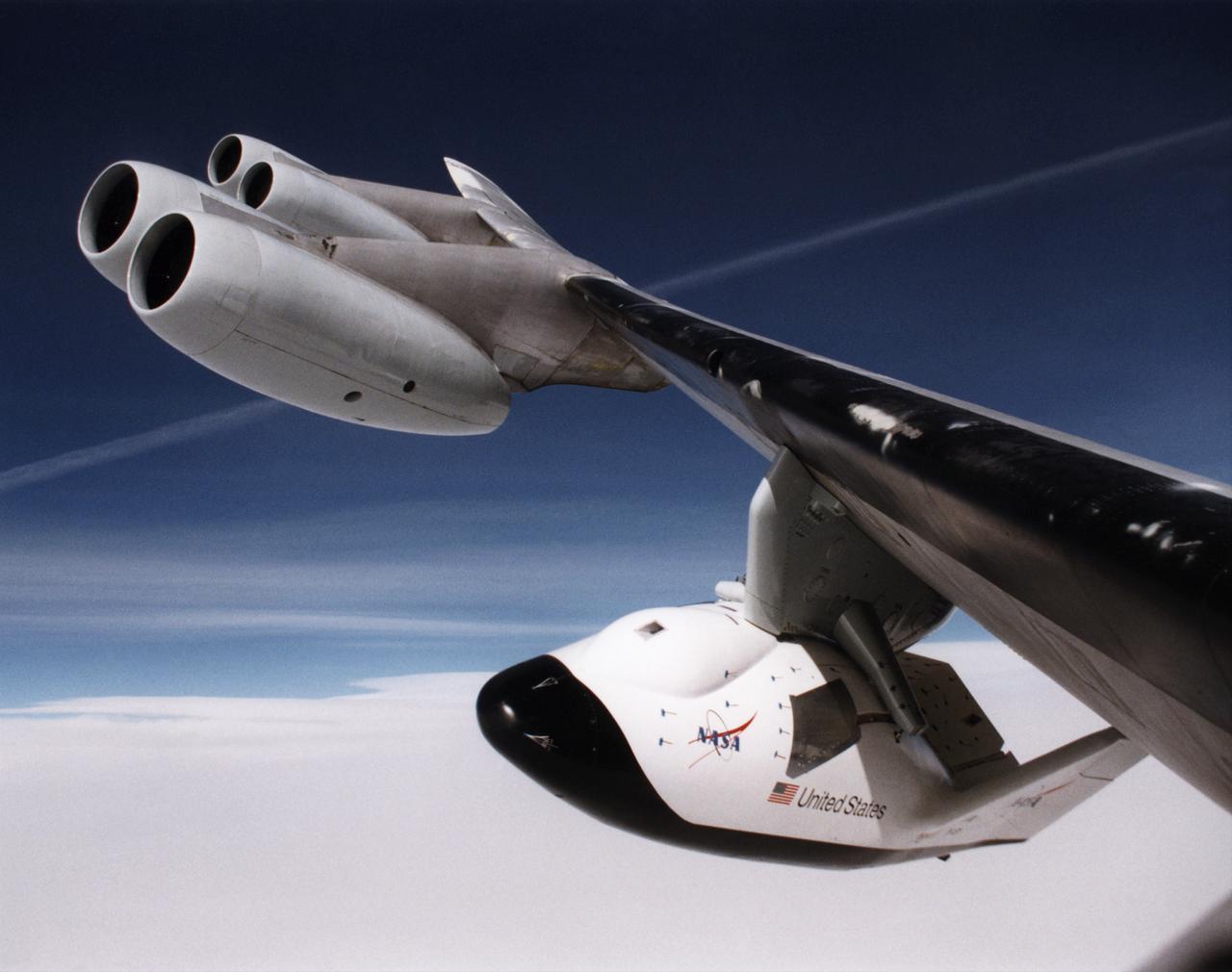
Sierra Nevada Corporation’s Dream Chaser completed an important step toward orbital flight with a successful captive carry test at NASA’s Armstrong Flight Research Center in California, located on Edwards Air Force Base. A helicopter successfully carried a Dream Chaser test article, which has the same specifications as a flight-ready spacecraft, to the same altitude and flight conditions of an upcoming free flight test. The Dream Chaser is a lifting-body, winged spacecraft that will fly back to Earth in a manner similar to NASA’s space shuttles. The successful captive carry test clears the way for a free flight test of the spacecraft later this year in which the uncrewed Dream Chaser will be released to glide on its own and land.
CAPE CANAVERAL, Fla. – Inside Orbiter Processing Facility-2 at NASA’s Kennedy Space Center in Florida, technicians monitor the progress as a special crane lifts one of the three fuel cells away from space shuttle Atlantis’ payload bay. The fuel cells will be drained of all fluids. The hydrogen and oxygen dewars which feed reactants to the fuel cells remain in Atlantis’ mid-body and will be purged with inert gases and vented down. The work is part of the Space Shuttle Program’s transition and retirement processing of shuttle Atlantis. The orbiter is being prepared for display at the Kennedy Space Center Visitor Complex. Photo credit: NASA/Kim Shiflett
CAPE CANAVERAL, Fla. – Inside Orbiter Processing Facility-2 at NASA’s Kennedy Space Center in Florida, technicians assist as a special crane is used to lift one of the three fuel cells away from space shuttle Atlantis’ payload bay. The fuel cells will be drained of all fluids. The hydrogen and oxygen dewars which feed reactants to the fuel cells remain in Atlantis’ mid-body and will be purged with inert gases and vented down. The work is part of the Space Shuttle Program’s transition and retirement processing of shuttle Atlantis. The orbiter is being prepared for display at the Kennedy Space Center Visitor Complex. Photo credit: NASA/Kim Shiflett
CAPE CANAVERAL, Fla. – Inside Orbiter Processing Facility-2 at NASA’s Kennedy Space Center in Florida, a technician assists as a special crane is used to lift one of the three fuel cells away from space shuttle Atlantis’ payload bay. The fuel cells will be drained of all fluids. The hydrogen and oxygen dewars which feed reactants to the fuel cells remain in Atlantis’ mid-body and will be purged with inert gases and vented down. The work is part of the Space Shuttle Program’s transition and retirement processing of shuttle Atlantis. The orbiter is being prepared for display at the Kennedy Space Center Visitor Complex. Photo credit: NASA/Kim Shiflett
CAPE CANAVERAL, Fla. – Inside Orbiter Processing Facility-2 at NASA’s Kennedy Space Center in Florida, technicians assist as a special crane is used to lift one of the three fuel cells away from space shuttle Atlantis’ payload bay. The fuel cells will be drained of all fluids. The hydrogen and oxygen dewars which feed reactants to the fuel cells remain in Atlantis’ mid-body and will be purged with inert gases and vented down. The work is part of the Space Shuttle Program’s transition and retirement processing of shuttle Atlantis. The orbiter is being prepared for display at the Kennedy Space Center Visitor Complex. Photo credit: NASA/Kim Shiflett
CAPE CANAVERAL, Fla. – Inside Orbiter Processing Facility-2 at NASA’s Kennedy Space Center in Florida, technicians monitor the progress as a special crane lifts one of the three fuel cells away from space shuttle Atlantis’ for securing on a special platform. The fuel cells will be drained of all fluids. The hydrogen and oxygen dewars which feed reactants to the fuel cells remain in Atlantis’ mid-body and will be purged with inert gases and vented down. The work is part of the Space Shuttle Program’s transition and retirement processing of shuttle Atlantis. The orbiter is being prepared for display at the Kennedy Space Center Visitor Complex. Photo credit: NASA/Kim Shiflett
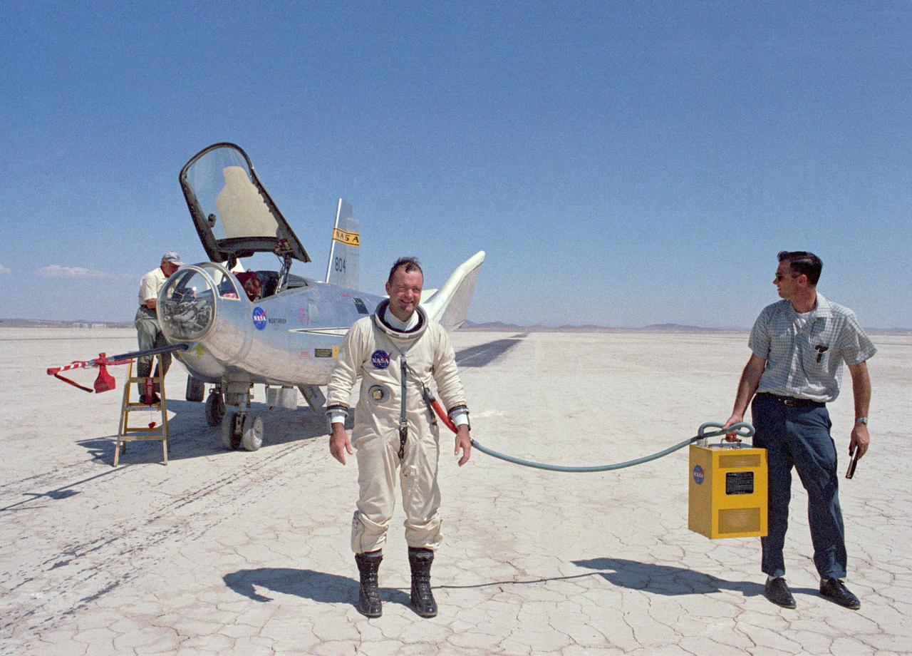
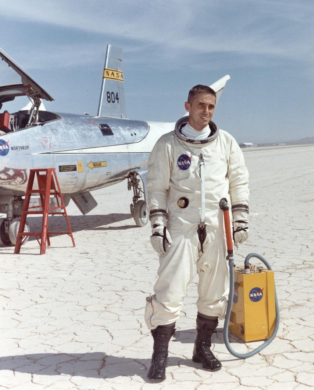
NASA research pilot Bill Dana after his fourth free flight (1 glide and 3 powered) in the HL-10. This particular flight reached a maximum speed of Mach 1.45. Dana made a total of nine HL-10 flights (1 glide and 8 powered), and his lifting body experience as a whole included several car tow and 1 air tow flights in the M2-F1; 4 glide and 15 powered flights in the M2-F3; and 2 powered flights in the X-24B. He is wearing a pressure suit for protection against the cockpit depressurizing at high altitudes. The air conditioner box held by the ground crewman provides cool air to prevent overheating.
Following the first M2-F1 airtow flight on 16 August 1963, the Flight Research Center used the vehicle for both research flights and to check out new lifting-body pilots. These included Bruce Peterson, Don Mallick, Fred Haise, and Bill Dana from NASA. Air Force pilots who flew the M2-F1 included Chuck Yeager, Jerry Gentry, Joe Engle, Jim Wood, and Don Sorlie, although Wood, Haise, and Engle only flew on car tows. In the three years between the first and last flights of the M2-F1, it made about 400 car tows and 77 air tows.
KENNEDY SPACE CENTER, FLA. -- At Astrotech, an overhead crane lifts the Dawn spacecraft from its stand to move and mate it to the upper stage booster for launch. Dawn is scheduled to launch July 7 from Pad 17-B on Cape Canaveral Air Force Station. Dawn's goal is to characterize the conditions and processes of the solar system's earliest epoch by investigating in detail the largest protoplanets that have remained intact since their formations: asteroid Vesta and the dwarf planet Ceres. They reside in the extensive zone between Mars and Jupiter together with many other smaller bodies, called the asteroid belt. Photo credit: NASA/George Shelton
KENNEDY SPACE CENTER, FLA. -- NASA's Dawn spacecraft, mated to the Delta II upper stage booster, arrives at Launch Pad 17-B at Cape Canaveral Air Force Station. It will be lifted into the mobile service tower for mating to the Delta II launch vehicle. Launch is scheduled for July 7. Dawn is the ninth mission in NASA's Discovery Program. The spacecraft will be the first to orbit two planetary bodies, asteroid Vesta and dwarf planet Ceres, during a single mission. Vesta and Ceres lie in the asteroid belt between Mars and Jupiter. It is also NASA's first purely scientific mission powered by three solar electric ion propulsion engines. Photo credit: NASA/Troy Cryder.