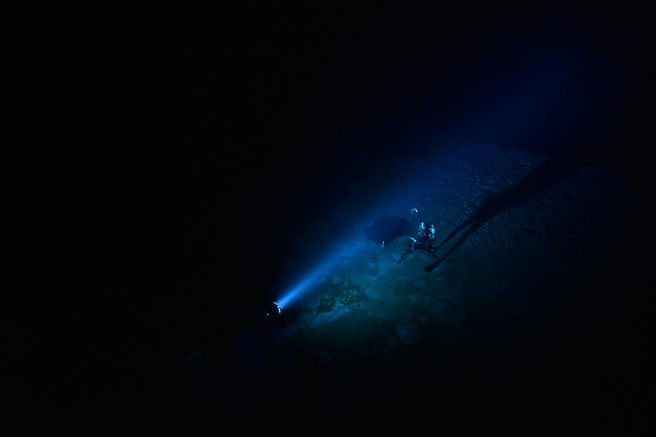
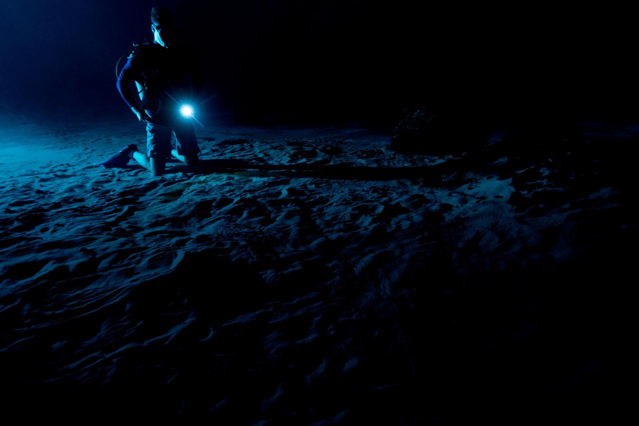
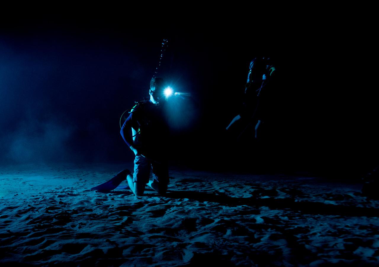
Quantitative evaluation of light source by NBL diver during NBL Preliminary Lunar Lighting Evaluation. Divers at the Neutral Buoyancy Laboratory (NBL) in Houston are setting the stage for future Moonwalk training by simulating lunar lighting conditions. At the Lunar South Pole, the Sun will remain no more than a few degrees above the horizon, resulting in extremely long and dark shadows. To prepare astronauts for these challenging lighting conditions, the team at the NBL has begun preliminary evaluations of lunar lighting solutions at the bottom of the 40-foot deep pool. This testing and evaluation involved turning off all the lights in the facility, installing black curtains on the pool walls to minimize reflections, and using a powerful underwater cinematic lamp, to get the conditions just right ahead of upcoming training for astronauts.
Quantitative evaluation of light source by NBL diver during NBL Preliminary Lunar Lighting Evaluation. Divers at the Neutral Buoyancy Laboratory (NBL) in Houston are setting the stage for future Moonwalk training by simulating lunar lighting conditions. At the Lunar South Pole, the Sun will remain no more than a few degrees above the horizon, resulting in extremely long and dark shadows. To prepare astronauts for these challenging lighting conditions, the team at the NBL has begun preliminary evaluations of lunar lighting solutions at the bottom of the 40-foot deep pool. This testing and evaluation involved turning off all the lights in the facility, installing black curtains on the pool walls to minimize reflections, and using a powerful underwater cinematic lamp, to get the conditions just right ahead of upcoming training for astronauts.
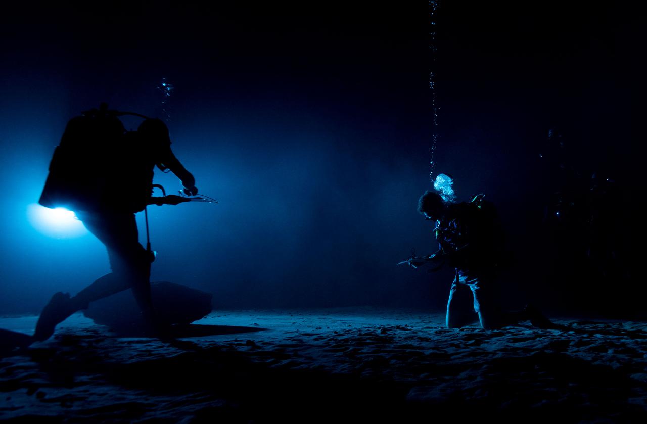
Test subjects performing mission-relevant tasks and evaluating shadow quality during NBL Preliminary Lunar Lighting Evaluation. Divers at the Neutral Buoyancy Laboratory (NBL) in Houston are setting the stage for future Moonwalk training by simulating lunar lighting conditions. At the Lunar South Pole, the Sun will remain no more than a few degrees above the horizon, resulting in extremely long and dark shadows. To prepare astronauts for these challenging lighting conditions, the team at the NBL has begun preliminary evaluations of lunar lighting solutions at the bottom of the 40-foot deep pool. This testing and evaluation involved turning off all the lights in the facility, installing black curtains on the pool walls to minimize reflections, and using a powerful underwater cinematic lamp, to get the conditions just right ahead of upcoming training for astronauts.
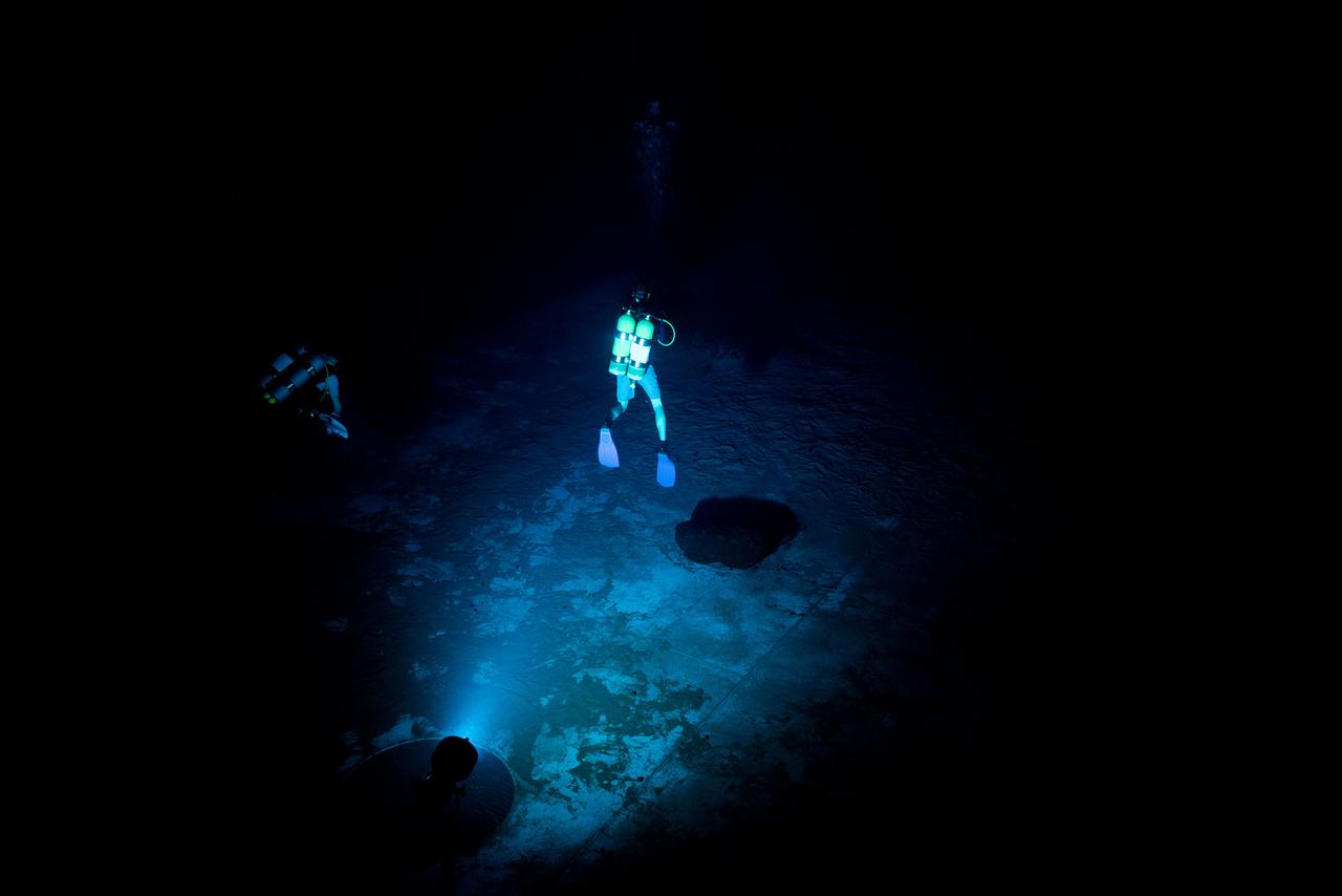
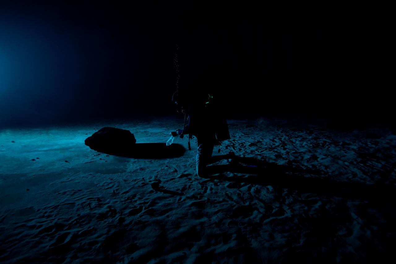
Test subjects performing subjective assessment of supplemental lighting during NBL Preliminary Lunar Lighting Evaluation. Divers at the Neutral Buoyancy Laboratory (NBL) in Houston are setting the stage for future Moonwalk training by simulating lunar lighting conditions. At the Lunar South Pole, the Sun will remain no more than a few degrees above the horizon, resulting in extremely long and dark shadows. To prepare astronauts for these challenging lighting conditions, the team at the NBL has begun preliminary evaluations of lunar lighting solutions at the bottom of the 40-foot deep pool. This testing and evaluation involved turning off all the lights in the facility, installing black curtains on the pool walls to minimize reflections, and using a powerful underwater cinematic lamp, to get the conditions just right ahead of upcoming training for astronauts.
Test subjects performing subjective assessment of supplemental lighting during NBL Preliminary Lunar Lighting Evaluation. Divers at the Neutral Buoyancy Laboratory (NBL) in Houston are setting the stage for future Moonwalk training by simulating lunar lighting conditions. At the Lunar South Pole, the Sun will remain no more than a few degrees above the horizon, resulting in extremely long and dark shadows. To prepare astronauts for these challenging lighting conditions, the team at the NBL has begun preliminary evaluations of lunar lighting solutions at the bottom of the 40-foot deep pool. This testing and evaluation involved turning off all the lights in the facility, installing black curtains on the pool walls to minimize reflections, and using a powerful underwater cinematic lamp, to get the conditions just right ahead of upcoming training for astronauts.
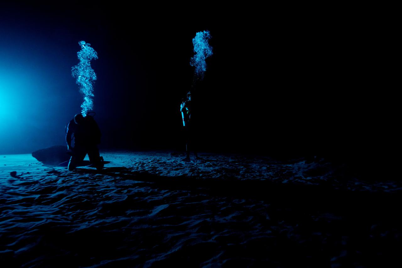
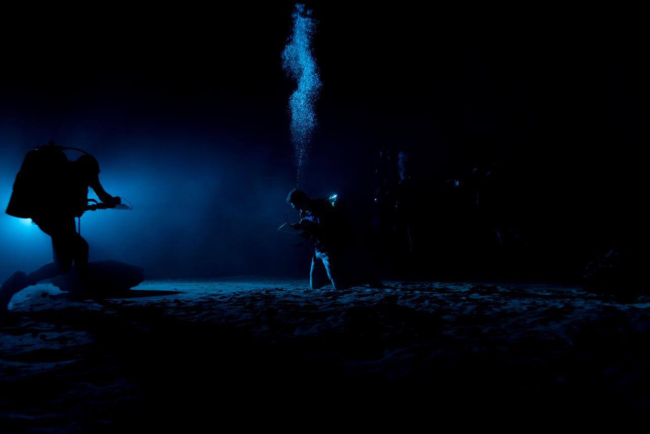
Test subjects performing subjective assessment of underwater lamp source during NBL Preliminary Lunar Lighting Evaluation. Divers at the Neutral Buoyancy Laboratory (NBL) in Houston are setting the stage for future Moonwalk training by simulating lunar lighting conditions. At the Lunar South Pole, the Sun will remain no more than a few degrees above the horizon, resulting in extremely long and dark shadows. To prepare astronauts for these challenging lighting conditions, the team at the NBL has begun preliminary evaluations of lunar lighting solutions at the bottom of the 40-foot deep pool. This testing and evaluation involved turning off all the lights in the facility, installing black curtains on the pool walls to minimize reflections, and using a powerful underwater cinematic lamp, to get the conditions just right ahead of upcoming training for astronauts.
Test subjects performing subjective assessment of underwater lamp source during NBL Preliminary Lunar Lighting Evaluation. Divers at the Neutral Buoyancy Laboratory (NBL) in Houston are setting the stage for future Moonwalk training by simulating lunar lighting conditions. At the Lunar South Pole, the Sun will remain no more than a few degrees above the horizon, resulting in extremely long and dark shadows. To prepare astronauts for these challenging lighting conditions, the team at the NBL has begun preliminary evaluations of lunar lighting solutions at the bottom of the 40-foot deep pool. This testing and evaluation involved turning off all the lights in the facility, installing black curtains on the pool walls to minimize reflections, and using a powerful underwater cinematic lamp, to get the conditions just right ahead of upcoming training for astronauts.
Test subjects performing subjective assessment of underwater lamp source during NBL Preliminary Lunar Lighting Evaluation. Divers at the Neutral Buoyancy Laboratory (NBL) in Houston are setting the stage for future Moonwalk training by simulating lunar lighting conditions. At the Lunar South Pole, the Sun will remain no more than a few degrees above the horizon, resulting in extremely long and dark shadows. To prepare astronauts for these challenging lighting conditions, the team at the NBL has begun preliminary evaluations of lunar lighting solutions at the bottom of the 40-foot deep pool. This testing and evaluation involved turning off all the lights in the facility, installing black curtains on the pool walls to minimize reflections, and using a powerful underwater cinematic lamp, to get the conditions just right ahead of upcoming training for astronauts.
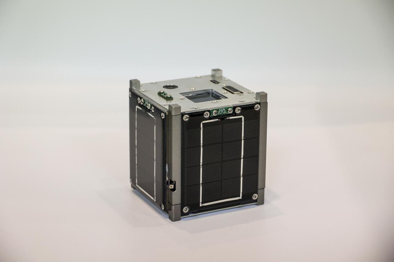
jsc2022e057881 (2/25/2022) --- Launch configuration of the HSU-SAT1 1-Unit (1U) CubeSat. HSU-SAT1 provides a demonstration that modulated infrared light emitted from a ground station can be used as a command transmission link. HSU-SAT1 also evaluates new technologies for electrical power supply, on board computing, and other satellite bus components. Image courtesy of Future Science Institute.
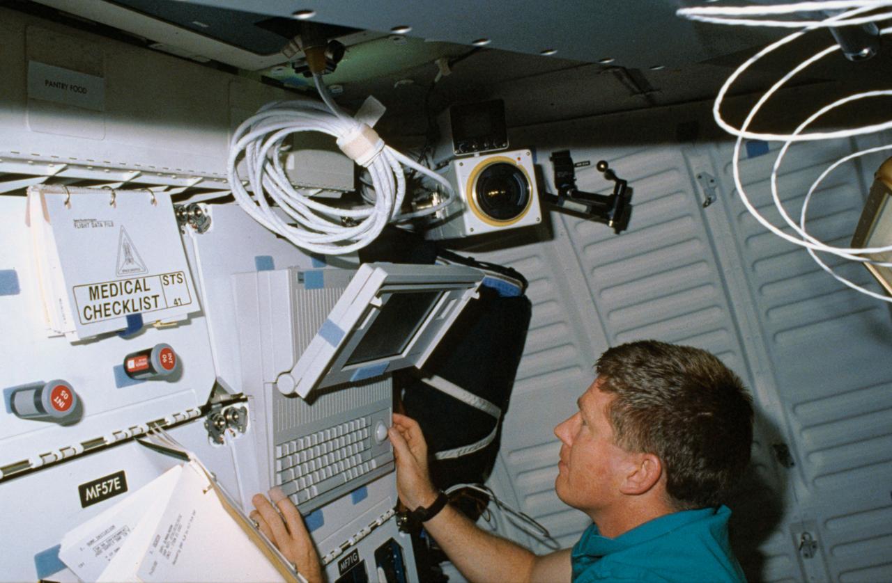
STS-41 Mission Specialist (MS) William M. Shepherd uses Detailed Test Objective (DTO) Space Station Cursor Control Device Evaluation MACINTOSH portable computer on the middeck of Discovery, Orbiter Vehicle (OV) 103. The computer is velcroed to forward lockers MF71C and MF71E. Surrounding Shepherd are checklists, the field sequential (FS) crew cabin camera, and a lighting fixture.
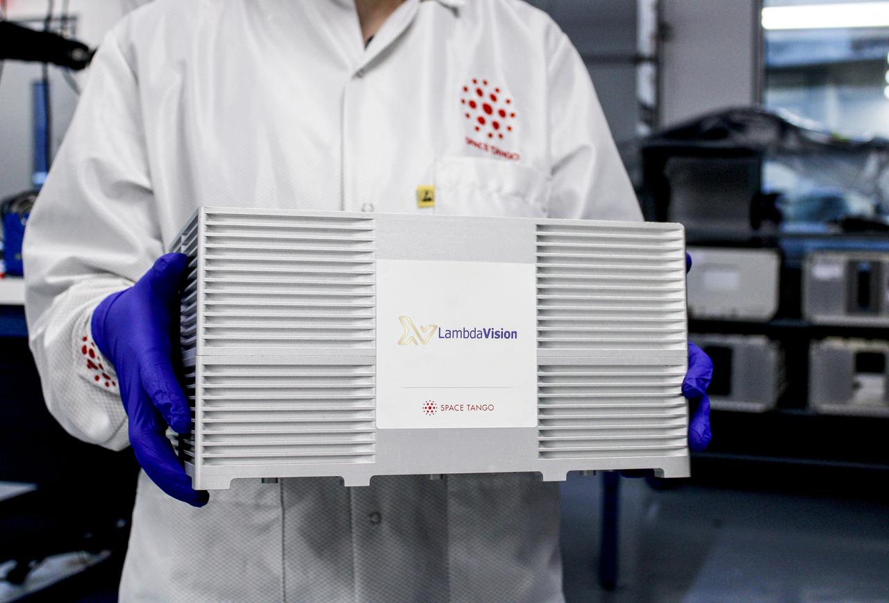
jsc2021e007776 (2/5/2021) --- Researchers move the CubeLab that contains a new LambdaVision investigation, Characterization of the Function and Stability of Bacteriorhodopsin Following Exposure to a Microgravity Environment (Protein-Based Artificial Retina Manufacturing). Protein-Based Artificial Retina Manufacturing evaluates a manufacturing system that uses a light-activated protein that replaces the function of damaged cells in the eye. Image courtesy of LambdaVision.
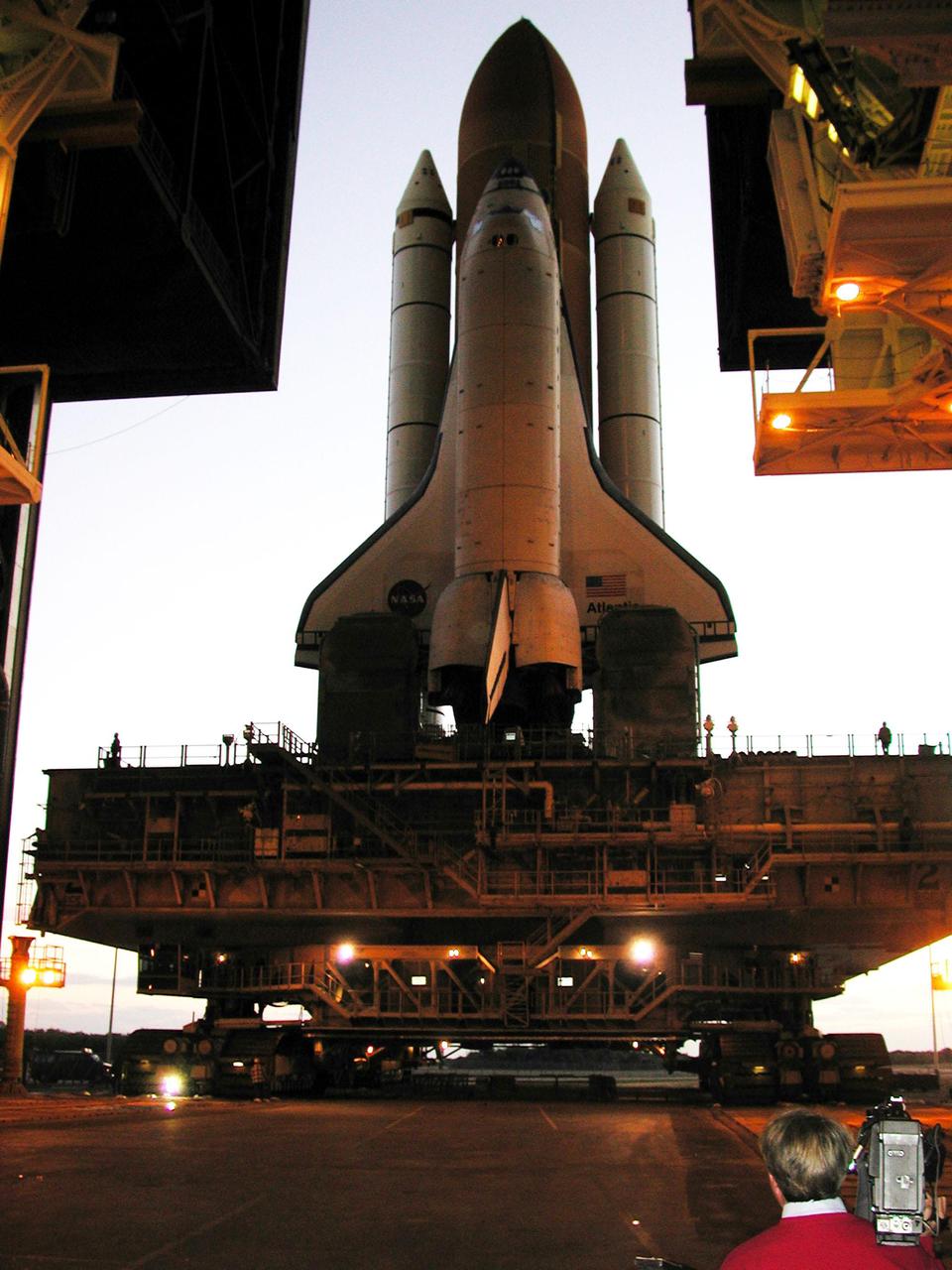
KENNEDY SPACE CENTER, Fla. -- Reflecting light from framework inside the Vehicle Assembly Building, Space Shuttle Atlantis begins rolling out of the VAB to Launch Pad 39A after tests were completed on the solid rocket booster cables. A prior extensive evaluation of NASA’s SRB cable inventory on the shelf revealed conductor damage in four (of about 200) cables. Shuttle managers decided to prove the integrity of the system tunnel cables already on Atlantis, causing return of the Shuttle to the VAB a week ago. Launch of Atlantis on STS-98 has been rescheduled to Feb. 7 at 6:11 p.m. EST
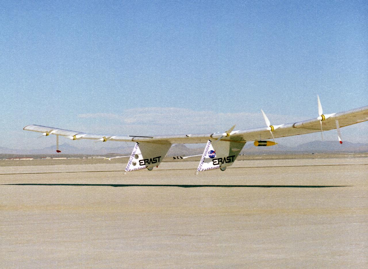
The Pathfinder solar-powered research aircraft settles in for landing on the bed of Rogers Dry Lake at the Dryden Flight Research Center, Edwards, California, after a successful test flight Nov. 19, 1996. The ultra-light craft flew a racetrack pattern at low altitudes over the flight test area for two hours while project engineers checked out various systems and sensors on the uninhabited aircraft. The Pathfinder was controlled by two pilots, one in a mobile control unit which followed the craft, the other in a stationary control station. Pathfinder, developed by AeroVironment, Inc., is one of several designs being evaluated under NASA's Environmental Research Aircraft and Sensor Technology (ERAST) program.
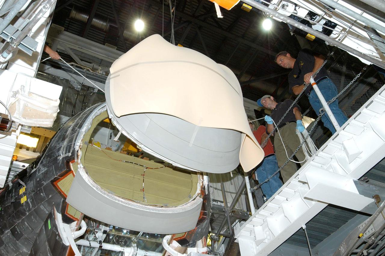
KENNEDY SPACE CENTER, FLA. - In the Orbiter Processing Facility, workers help install the nose cap on the orbiter Atlantis. The nose cap was removed from the vehicle in May and sent back to the vendor for thorough Non-Destructive Engineering evaluation and recoating. Thermography was also performed to check for internal flaws. This procedure uses high intensity light to heat areas that are immediately scanned with an infrared camera. White Thermal Protection System blankets were reinstalled on the nose cap before installation. Processing continues on Atlantis for its future mission to the International Space Station.

KENNEDY SPACE CENTER, FLA. - In the Orbiter Processing Facility, a newly installed nose cap on the orbiter Atlantis looks pristine amid the complexities of other equipment. The nose cap was removed from the vehicle in May and sent back to the vendor for thorough Non-Destructive Engineering evaluation and recoating. Thermography was also performed to check for internal flaws. This procedure uses high intensity light to heat areas that are immediately scanned with an infrared camera. White Thermal Protection System blankets were reinstalled on the nose cap before installation. Processing continues on Atlantis for its future mission to the International Space Station.
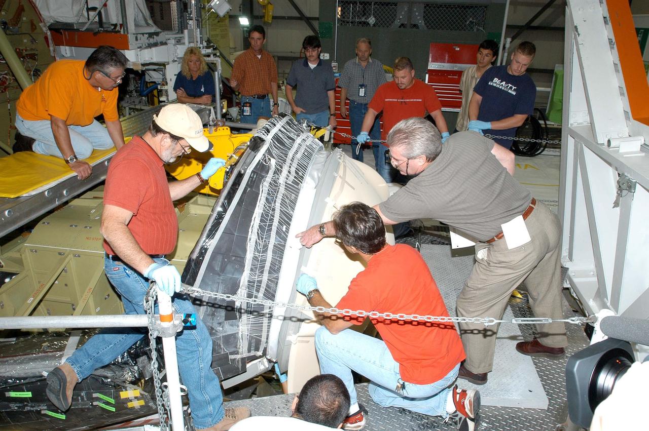
KENNEDY SPACE CENTER, FLA. - In the Orbiter Processing Facility, workers check the fit of the nose cap (right) after installation on the orbiter Atlantis. The nose cap was removed from the vehicle in May and sent back to the vendor for thorough Non-Destructive Engineering evaluation and recoating. Thermography was also performed to check for internal flaws. This procedure uses high intensity light to heat areas that are immediately scanned with an infrared camera. White Thermal Protection System blankets were reinstalled on the nose cap before installation. Processing continues on Atlantis for its future mission to the International Space Station.

KENNEDY SPACE CENTER, FLA. - In the Orbiter Processing Facility, workers lower the nose cap toward the orbiter Atlantis for installation. The nose cap was removed from the vehicle in May and sent back to the vendor for thorough Non-Destructive Engineering evaluation and recoating. Thermography was also performed to check for internal flaws. This procedure uses high intensity light to heat areas that are immediately scanned with an infrared camera. White Thermal Protection System blankets were reinstalled on the nose cap before installation. Processing continues on Atlantis for its future mission to the International Space Station.
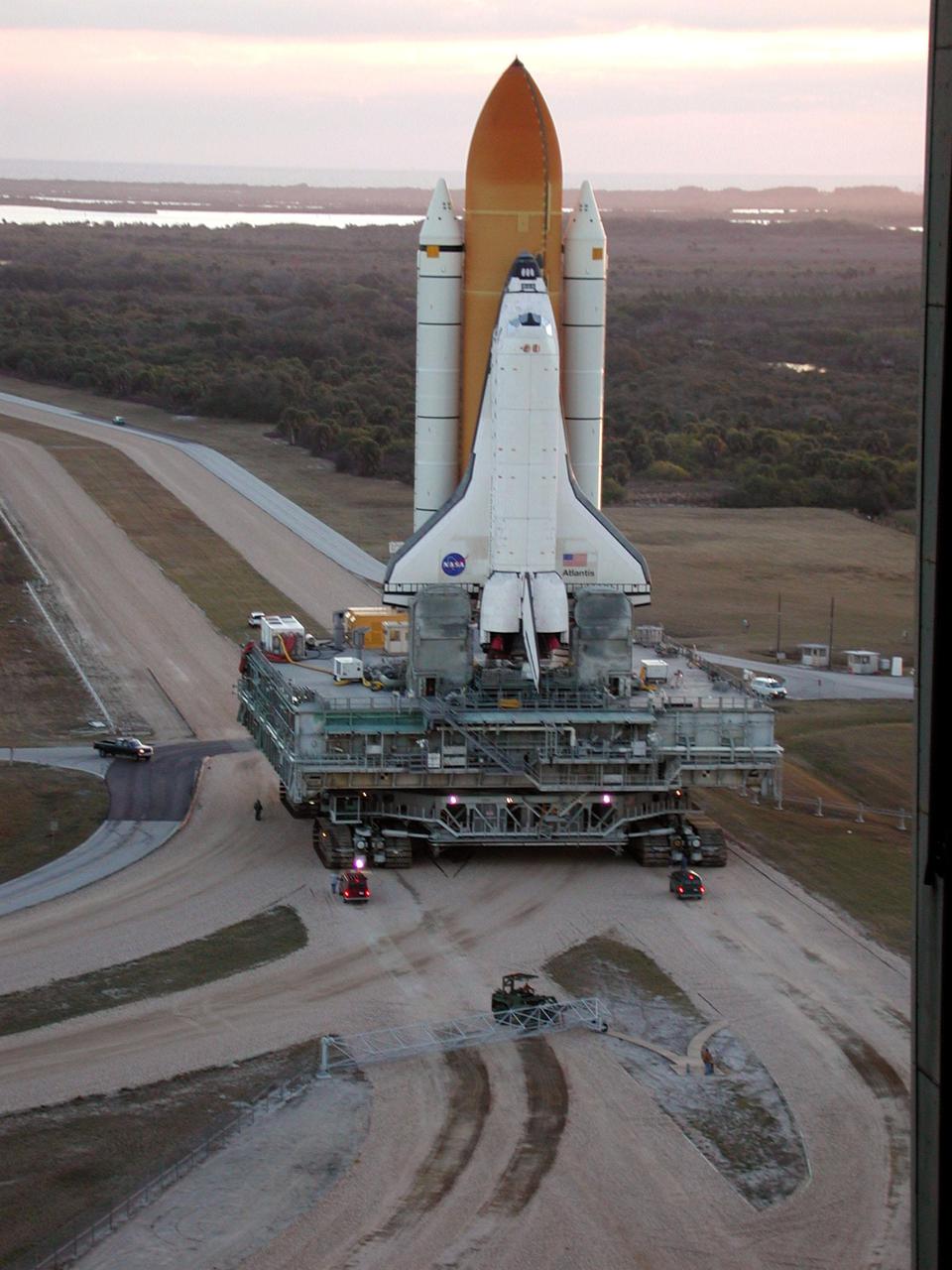
KENNEDY SPACE CENTER, Fla. -- In the early morning light, Space Shuttle Atlantis makes the turn from the Vehicle Assembly Building onto the crawlerway for the trek to Launch Pad 39A. The Shuttle has been in the VAB undergoing tests on the solid rocket booster cables. A prior extensive evaluation of NASA’s SRB cable inventory on the shelf revealed conductor damage in four (of about 200) cables. Shuttle managers decided to prove the integrity of the system tunnel cables already on Atlantis, causing return of the Shuttle to the VAB a week ago. Launch of Atlantis on STS-98 has been rescheduled to Feb. 7 at 6:11 p.m. EST
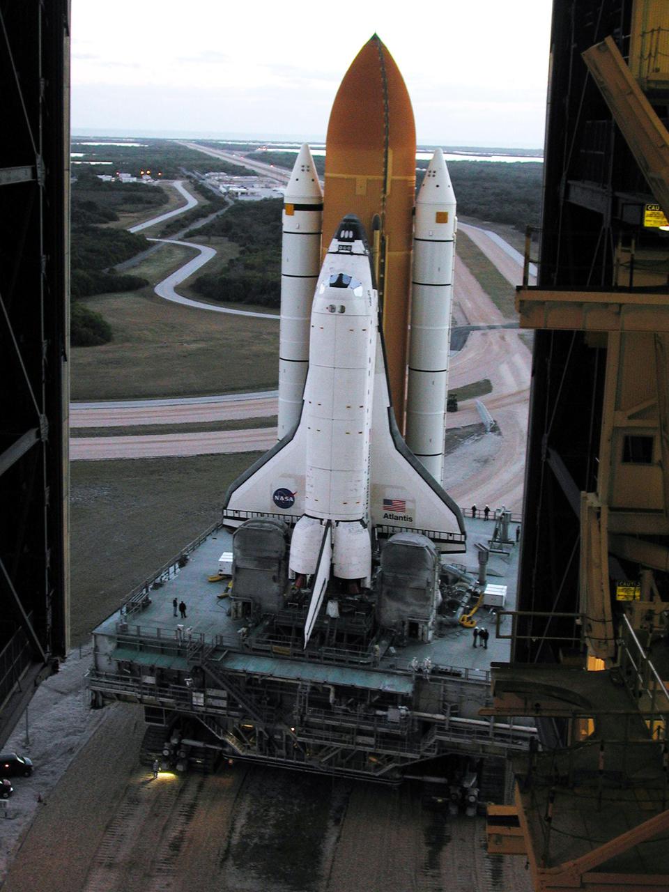
KENNEDY SPACE CENTER, Fla. -- Reflecting light from framework inside the Vehicle Assembly Building, Space Shuttle Atlantis begins rolling out of the VAB to Launch Pad 39A after tests were completed on the solid rocket booster cables. A prior extensive evaluation of NASA’s SRB cable inventory on the shelf revealed conductor damage in four (of about 200) cables. Shuttle managers decided to prove the integrity of the system tunnel cables already on Atlantis, causing return of the Shuttle to the VAB a week ago. Launch of Atlantis on STS-98 has been rescheduled to Feb. 7 at 6:11 p.m. EST

KENNEDY SPACE CENTER, FLA. - In the Orbiter Processing Facility, workers help install the nose cap (right) onto the orbiter Atlantis. The nose cap was removed from the vehicle in May and sent back to the vendor for thorough Non-Destructive Engineering evaluation and recoating. Thermography was also performed to check for internal flaws. This procedure uses high intensity light to heat areas that are immediately scanned with an infrared camera. White Thermal Protection System blankets were reinstalled on the nose cap before installation. Processing continues on Atlantis for its future mission to the International Space Station.
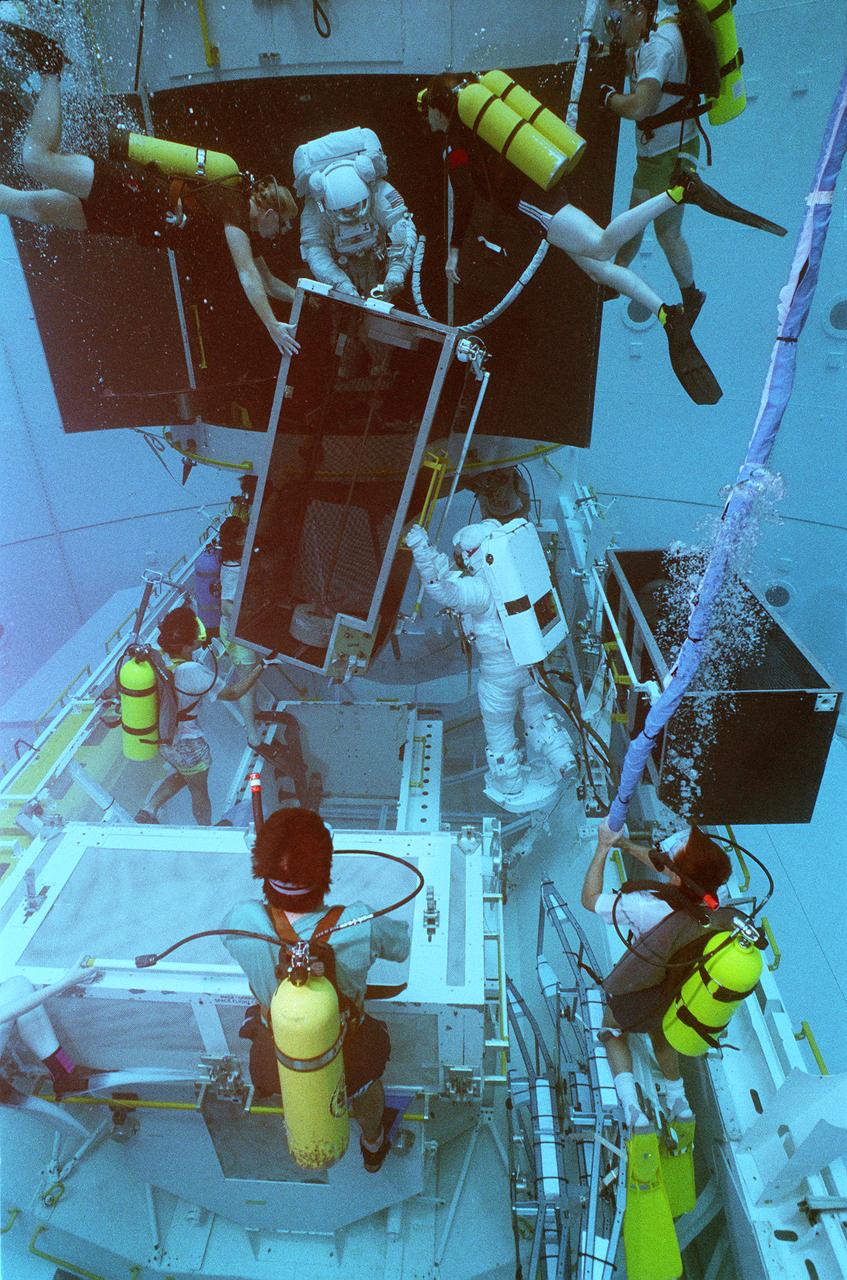
This photograph shows STS-61 crewmemmbers training for the Hubble Space Telescope (HST) servicing mission in the Marshall Space Flight Center's (MSFC's) Neutral Buoyancy Simulator (NBS). Two months after its deployment in space, scientists detected a 2-micron spherical aberration in the primary mirror of the HST that affected the telescope's ability to focus faint light sources into a precise point. This imperfection was very slight, one-fiftieth of the width of a human hair. A scheduled Space Service servicing mission (STS-61) in 1993 permitted scientists to correct the problem. The MSFC NBS provided an excellent environment for testing hardware to examine how it would operate in space and for evaluating techniques for space construction and spacecraft servicing.
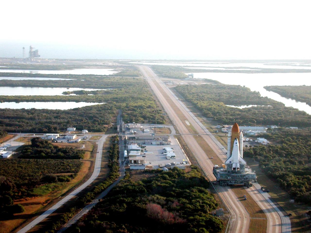
KENNEDY SPACE CENTER, Fla. -- As the early morning light casts a glow over the landscape, Space Shuttle Atlantis moves slowly along the crawlerway for the trek to Launch Pad 39A (upper left). The Shuttle has been in the VAB undergoing tests on the solid rocket booster cables. A prior extensive evaluation of NASA’s SRB cable inventory on the shelf revealed conductor damage in four (of about 200) cables. Shuttle managers decided to prove the integrity of the system tunnel cables already on Atlantis, causing return of the Shuttle to the VAB a week ago. Launch of Atlantis on STS-98 has been rescheduled to Feb. 7 at 6:11 p.m. EST

KENNEDY SPACE CENTER, Fla. -- Reflecting light from framework inside the Vehicle Assembly Building, Space Shuttle Atlantis begins rolling out of the VAB to Launch Pad 39A after tests were completed on the solid rocket booster cables. A prior extensive evaluation of NASA’s SRB cable inventory on the shelf revealed conductor damage in four (of about 200) cables. Shuttle managers decided to prove the integrity of the system tunnel cables already on Atlantis, causing return of the Shuttle to the VAB a week ago. Launch of Atlantis on STS-98 has been rescheduled to Feb. 7 at 6:11 p.m. EST
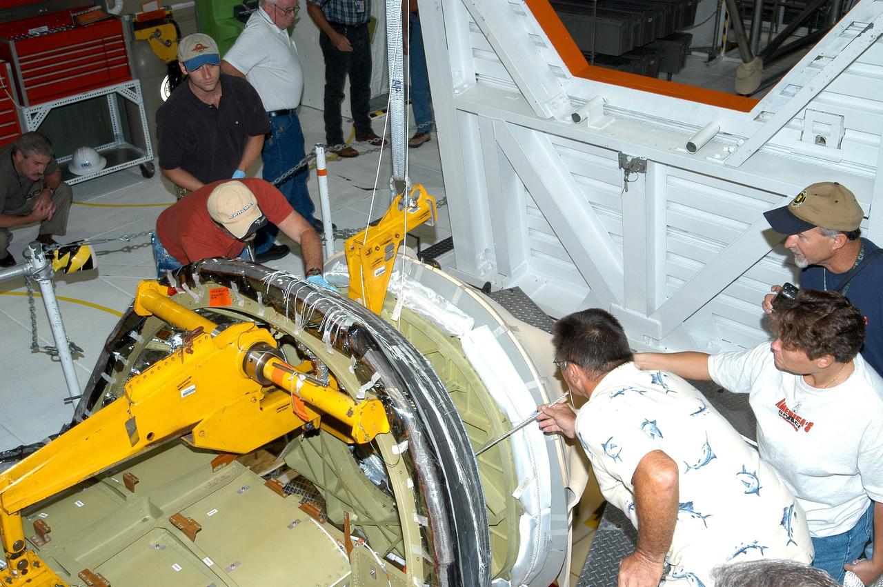
KENNEDY SPACE CENTER, FLA. - In the Orbiter Processing Facility, workers help guide the nose cap (right) toward the orbiter Atlantis for installation. The nose cap was removed from the vehicle in May and sent back to the vendor for thorough Non-Destructive Engineering evaluation and recoating. Thermography was also performed to check for internal flaws. This procedure uses high intensity light to heat areas that are immediately scanned with an infrared camera. White Thermal Protection System blankets were reinstalled on the nose cap before installation. Processing continues on Atlantis for its future mission to the International Space Station.

KENNEDY SPACE CENTER, Fla. -- Reflecting light from framework inside the Vehicle Assembly Building, Space Shuttle Atlantis begins rolling out of the VAB to Launch Pad 39A after tests were completed on the solid rocket booster cables. A prior extensive evaluation of NASA’s SRB cable inventory on the shelf revealed conductor damage in four (of about 200) cables. Shuttle managers decided to prove the integrity of the system tunnel cables already on Atlantis, causing return of the Shuttle to the VAB a week ago. Launch of Atlantis on STS-98 has been rescheduled to Feb. 7 at 6:11 p.m. EST
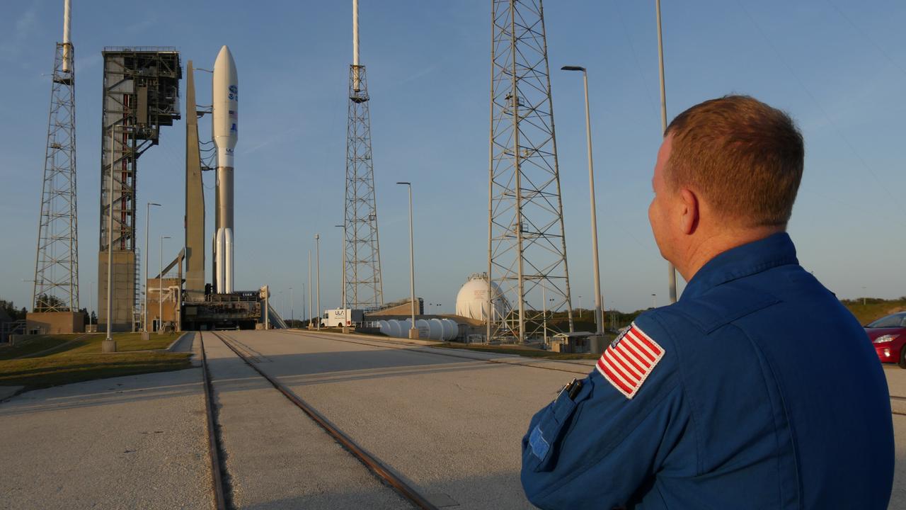
NASA astronaut Eric Boe, one of four astronauts working with the agency’s Commercial Crew Program, had the opportunity to check out the Crew Access Tower at Space Launch Complex 41 (SLC-41) Wednesday with a United Launch Alliance Atlas V on the pad. Boe, along with launch operations engineers from NASA, Boeing, and ULA, climbed the launch pad tower to evaluate lighting and spotlights after dark. The survey helped ensure crew members will have acceptable visibility as they prepare to launch aboard Boeing’s Starliner spacecraft on the Crew Flight Test to the International Space Station targeted for later this year.
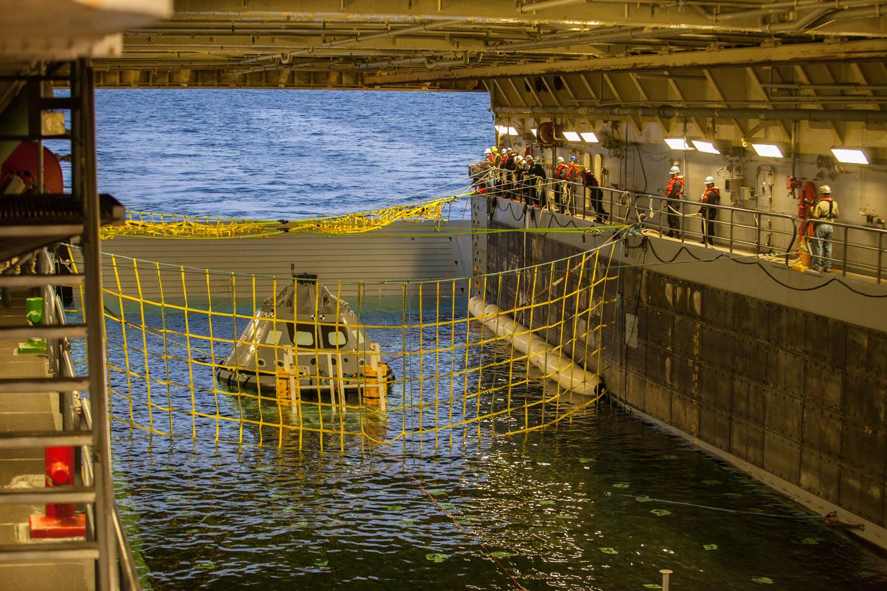
A golden sheen lights up a test version of the Orion crew module in the flooded well deck of the USS San Diego during Underway Recovery Test 5 in the Pacific Ocean off the coast of California on Oct. 26, 2016. Recovery team personnel have secured a net around the crew module. NASA's Ground Systems Development and Operations Program and the U.S. Navy will conduct a series of tests to prepare for recovery of Orion on its return from deep space missions. The testing will allow the team to demonstrate and evaluate recovery processes, procedures, hardware and personnel in open waters. Part of Batch images transfer from Flickr.
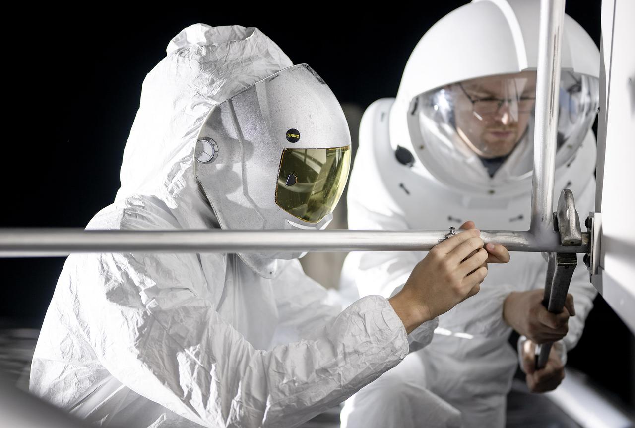
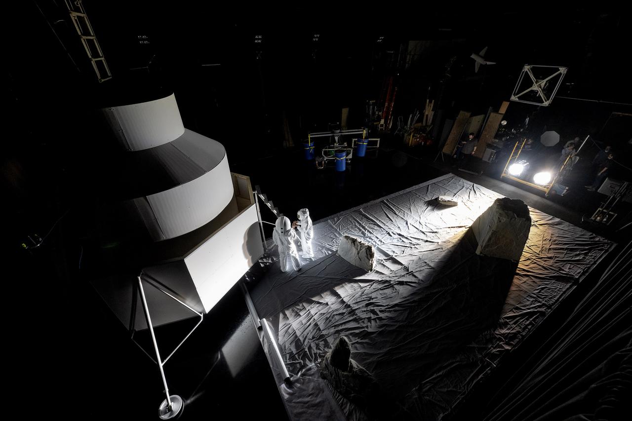
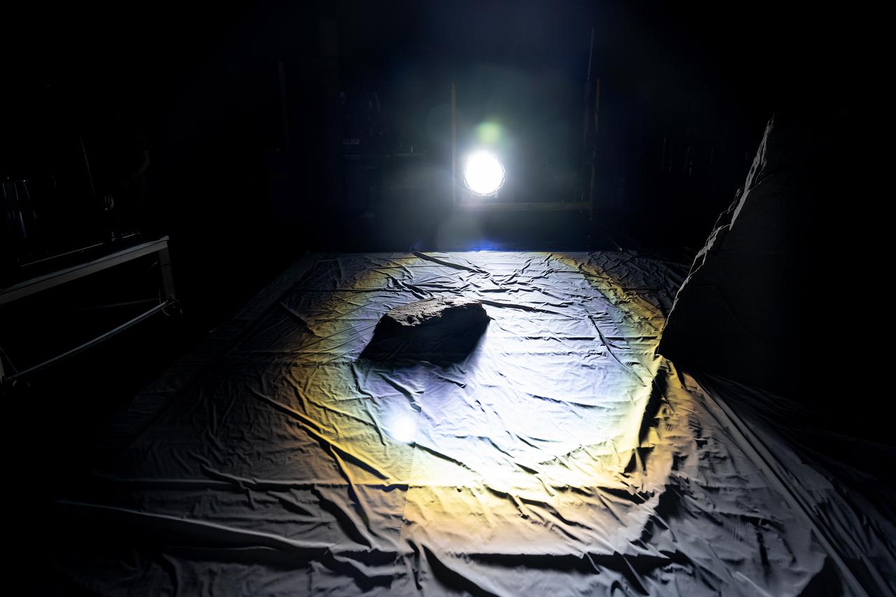
These photos show how teams at NASA’s Marshall Space Flight Center in Huntsville, Alabama, are using the Flat Floor Facility (Building 4619) to understand the lunar lighting environment in preparation for the Artemis III crewed lunar landing mission, slated for 2027. The Flat Floor Facility is an air-bearing floor, providing full-scale simulation capabilities for lunar surface systems by simulating zero gravity in two dimensions. Wearing low-fidelity materials, test engineers can understand how the extreme lighting of the Moon’s South Pole could affect surface operations during Artemis III. High-intensity lights are positioned at a low angle to replicate the strong shadows that are cast across the lunar South Pole by the Sun. Data and analysis from testing at NASA Marshall are improving models Artemis astronauts will use in preparation for lander and surface operations on the Moon during Artemis III. Testing in the facility is also helping cross-agency teams evaluate various tools astronauts may use. NASA Marshall manages the Human Landing System (HLS) Program. For more information, contact NASA Marshall’s Office of Communications at 256-544-0034.
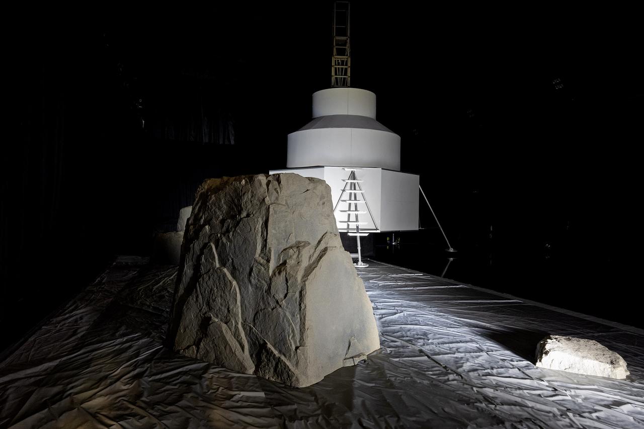
These photos show how teams at NASA’s Marshall Space Flight Center in Huntsville, Alabama, are using the Flat Floor Facility (Building 4619) to understand the lunar lighting environment in preparation for the Artemis III crewed lunar landing mission, slated for 2027. The Flat Floor Facility is an air-bearing floor, providing full-scale simulation capabilities for lunar surface systems by simulating zero gravity in two dimensions. Wearing low-fidelity materials, test engineers can understand how the extreme lighting of the Moon’s South Pole could affect surface operations during Artemis III. High-intensity lights are positioned at a low angle to replicate the strong shadows that are cast across the lunar South Pole by the Sun. Data and analysis from testing at NASA Marshall are improving models Artemis astronauts will use in preparation for lander and surface operations on the Moon during Artemis III. Testing in the facility is also helping cross-agency teams evaluate various tools astronauts may use. NASA Marshall manages the Human Landing System (HLS) Program. For more information, contact NASA Marshall’s Office of Communications at 256-544-0034.
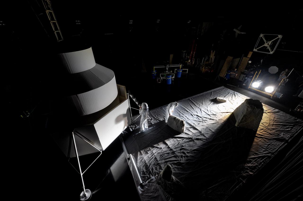
These photos show how teams at NASA’s Marshall Space Flight Center in Huntsville, Alabama, are using the Flat Floor Facility (Building 4619) to understand the lunar lighting environment in preparation for the Artemis III crewed lunar landing mission, slated for 2027. The Flat Floor Facility is an air-bearing floor, providing full-scale simulation capabilities for lunar surface systems by simulating zero gravity in two dimensions. Wearing low-fidelity materials, test engineers can understand how the extreme lighting of the Moon’s South Pole could affect surface operations during Artemis III. High-intensity lights are positioned at a low angle to replicate the strong shadows that are cast across the lunar South Pole by the Sun. Data and analysis from testing at NASA Marshall are improving models Artemis astronauts will use in preparation for lander and surface operations on the Moon during Artemis III. Testing in the facility is also helping cross-agency teams evaluate various tools astronauts may use. NASA Marshall manages the Human Landing System (HLS) Program. For more information, contact NASA Marshall’s Office of Communications at 256-544-0034.
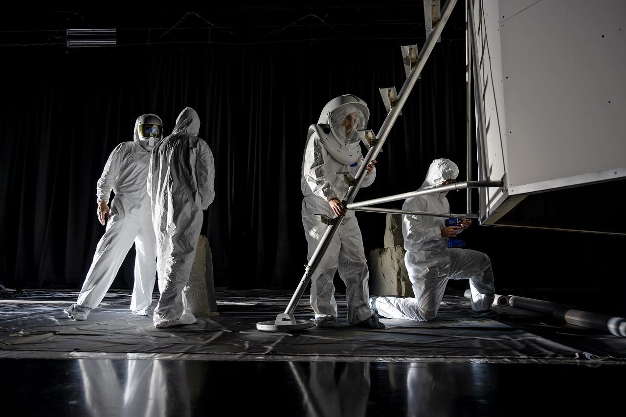
These photos show how teams at NASA’s Marshall Space Flight Center in Huntsville, Alabama, are using the Flat Floor Facility (Building 4619) to understand the lunar lighting environment in preparation for the Artemis III crewed lunar landing mission, slated for 2027. The Flat Floor Facility is an air-bearing floor, providing full-scale simulation capabilities for lunar surface systems by simulating zero gravity in two dimensions. Wearing low-fidelity materials, test engineers can understand how the extreme lighting of the Moon’s South Pole could affect surface operations during Artemis III. High-intensity lights are positioned at a low angle to replicate the strong shadows that are cast across the lunar South Pole by the Sun. Data and analysis from testing at NASA Marshall are improving models Artemis astronauts will use in preparation for lander and surface operations on the Moon during Artemis III. Testing in the facility is also helping cross-agency teams evaluate various tools astronauts may use. NASA Marshall manages the Human Landing System (HLS) Program. For more information, contact NASA Marshall’s Office of Communications at 256-544-0034.
These photos show how teams at NASA’s Marshall Space Flight Center in Huntsville, Alabama, are using the Flat Floor Facility (Building 4619) to understand the lunar lighting environment in preparation for the Artemis III crewed lunar landing mission, slated for 2027. The Flat Floor Facility is an air-bearing floor, providing full-scale simulation capabilities for lunar surface systems by simulating zero gravity in two dimensions. Wearing low-fidelity materials, test engineers can understand how the extreme lighting of the Moon’s South Pole could affect surface operations during Artemis III. High-intensity lights are positioned at a low angle to replicate the strong shadows that are cast across the lunar South Pole by the Sun. Data and analysis from testing at NASA Marshall are improving models Artemis astronauts will use in preparation for lander and surface operations on the Moon during Artemis III. Testing in the facility is also helping cross-agency teams evaluate various tools astronauts may use. NASA Marshall manages the Human Landing System (HLS) Program. For more information, contact NASA Marshall’s Office of Communications at 256-544-0034.

These photos show how teams at NASA’s Marshall Space Flight Center in Huntsville, Alabama, are using the Flat Floor Facility (Building 4619) to understand the lunar lighting environment in preparation for the Artemis III crewed lunar landing mission, slated for 2027. The Flat Floor Facility is an air-bearing floor, providing full-scale simulation capabilities for lunar surface systems by simulating zero gravity in two dimensions. Wearing low-fidelity materials, test engineers can understand how the extreme lighting of the Moon’s South Pole could affect surface operations during Artemis III. High-intensity lights are positioned at a low angle to replicate the strong shadows that are cast across the lunar South Pole by the Sun. Data and analysis from testing at NASA Marshall are improving models Artemis astronauts will use in preparation for lander and surface operations on the Moon during Artemis III. Testing in the facility is also helping cross-agency teams evaluate various tools astronauts may use. NASA Marshall manages the Human Landing System (HLS) Program. For more information, contact NASA Marshall’s Office of Communications at 256-544-0034.
These photos show how teams at NASA’s Marshall Space Flight Center in Huntsville, Alabama, are using the Flat Floor Facility (Building 4619) to understand the lunar lighting environment in preparation for the Artemis III crewed lunar landing mission, slated for 2027. The Flat Floor Facility is an air-bearing floor, providing full-scale simulation capabilities for lunar surface systems by simulating zero gravity in two dimensions. Wearing low-fidelity materials, test engineers can understand how the extreme lighting of the Moon’s South Pole could affect surface operations during Artemis III. High-intensity lights are positioned at a low angle to replicate the strong shadows that are cast across the lunar South Pole by the Sun. Data and analysis from testing at NASA Marshall are improving models Artemis astronauts will use in preparation for lander and surface operations on the Moon during Artemis III. Testing in the facility is also helping cross-agency teams evaluate various tools astronauts may use. NASA Marshall manages the Human Landing System (HLS) Program. For more information, contact NASA Marshall’s Office of Communications at 256-544-0034.
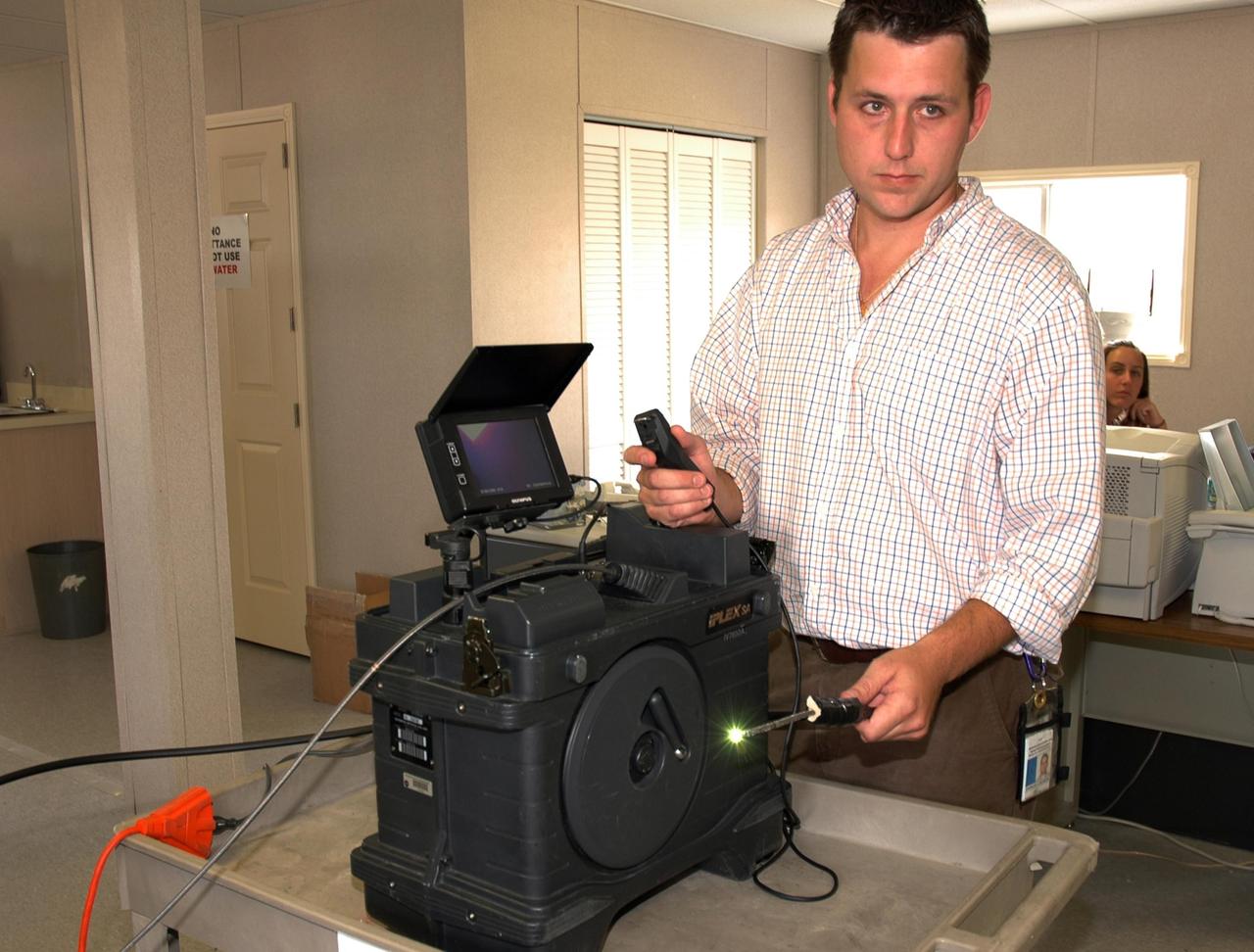
KENNEDY SPACE CENTER, FLA. - In the Press Site at NASA's Kennedy Space Center, Charles Wassen, with the United Space Alliance Micro Inspection Team, demonstrates the boroscope camera probe, with the light glowing, that was used to verify the condition of the foam on Space Shuttle Discovery's external tank. On July 2, a crack formed on a piece of insulation on a strut that attaches the liquid oxygen feedline to External Tank-119, being used to launch space shuttle mission STS-121. It was recovered by the Ice Team from the mobile launch platform at Pad 39B. The camera was used to get a closeup of the area for the mission management team to examine and evaluate if the launch attempt should proceed on July 4. Photo credit: NASA/Carl Winebarger
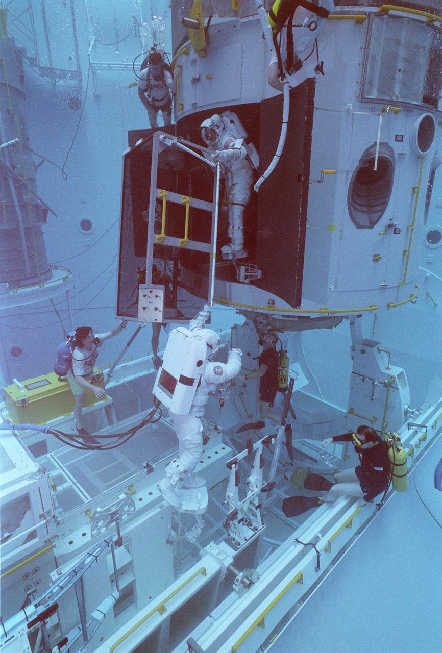
This photograph shows an STS-61 astronaut training for the Hubble Space Telescope (HST) servicing mission (STS-61) in the Marshall Space Flight Center's (MSFC's) Neutral Buoyancy Simulator (NBS). Two months after its deployment in space, scientists detected a 2-micron spherical aberration in the primary mirror of the HST that affected the telescope's ability to focus faint light sources into a precise point. This imperfection was very slight, one-fiftieth of the width of a human hair. A scheduled Space Service servicing mission (STS-61) in 1993 permitted scientists to correct the problem. The MSFC NBS provided an excellent environment for testing hardware to examine how it would operate in space and for evaluating techniques for space construction and spacecraft servicing.
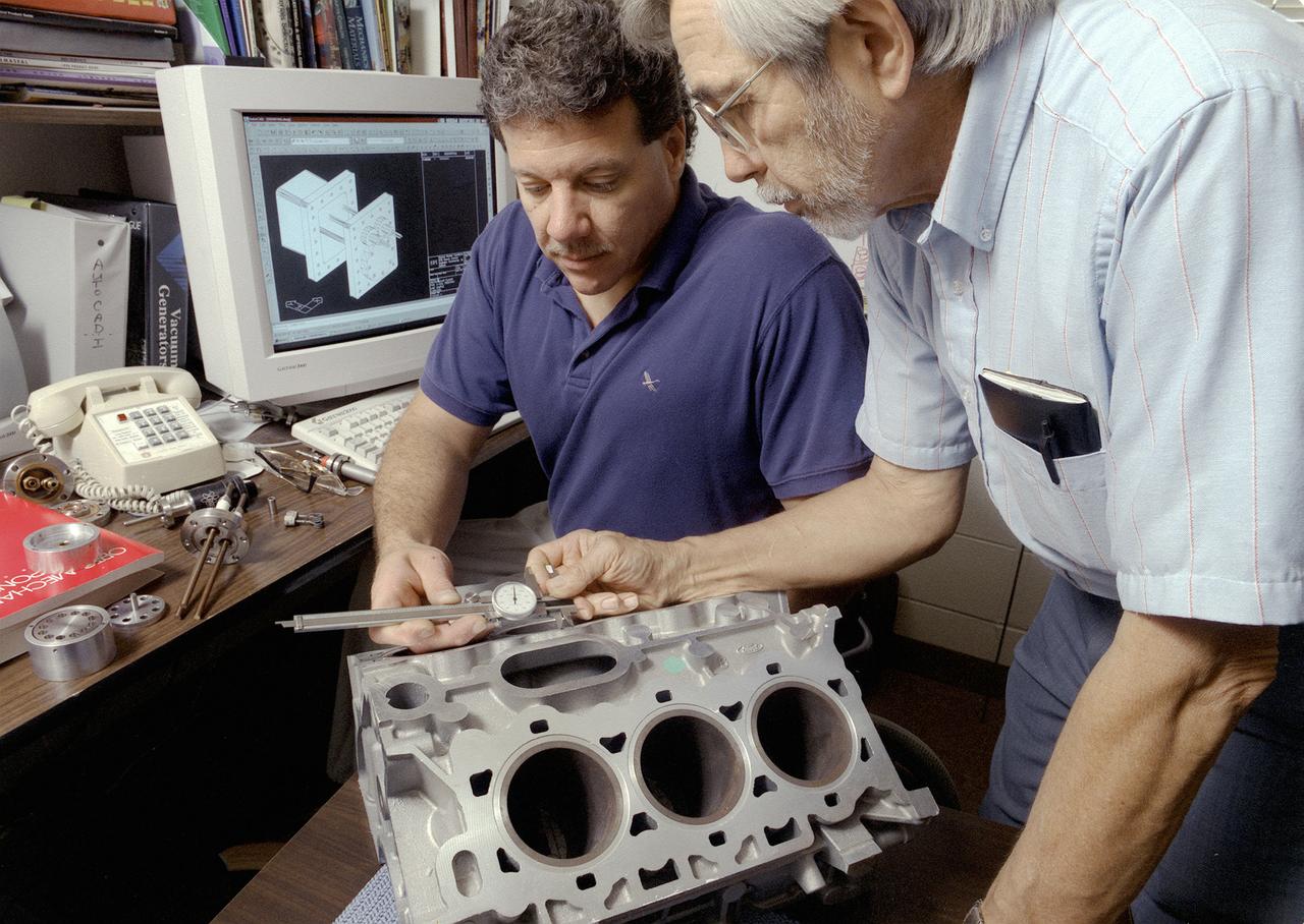
Don Sirois, an Auburn University research associate, and Bruce Strom, a mechanical engineering Co-Op Student, are evaluating the dimensional characteristics of an aluminum automobile engine casting. More accurate metal casting processes may reduce the weight of some cast metal products used in automobiles, such as engines. Research in low gravity has taken an important first step toward making metal products used in homes, automobiles, and aircraft less expensive, safer, and more durable. Auburn University and industry are partnering with NASA to develop one of the first accurate computer model predictions of molten metals and molding materials used in a manufacturing process called casting. Ford Motor Company's casting plant in Cleveland, Ohio is using NASA-sponsored computer modeling information to improve the casting process of automobile and light-truck engine blocks.
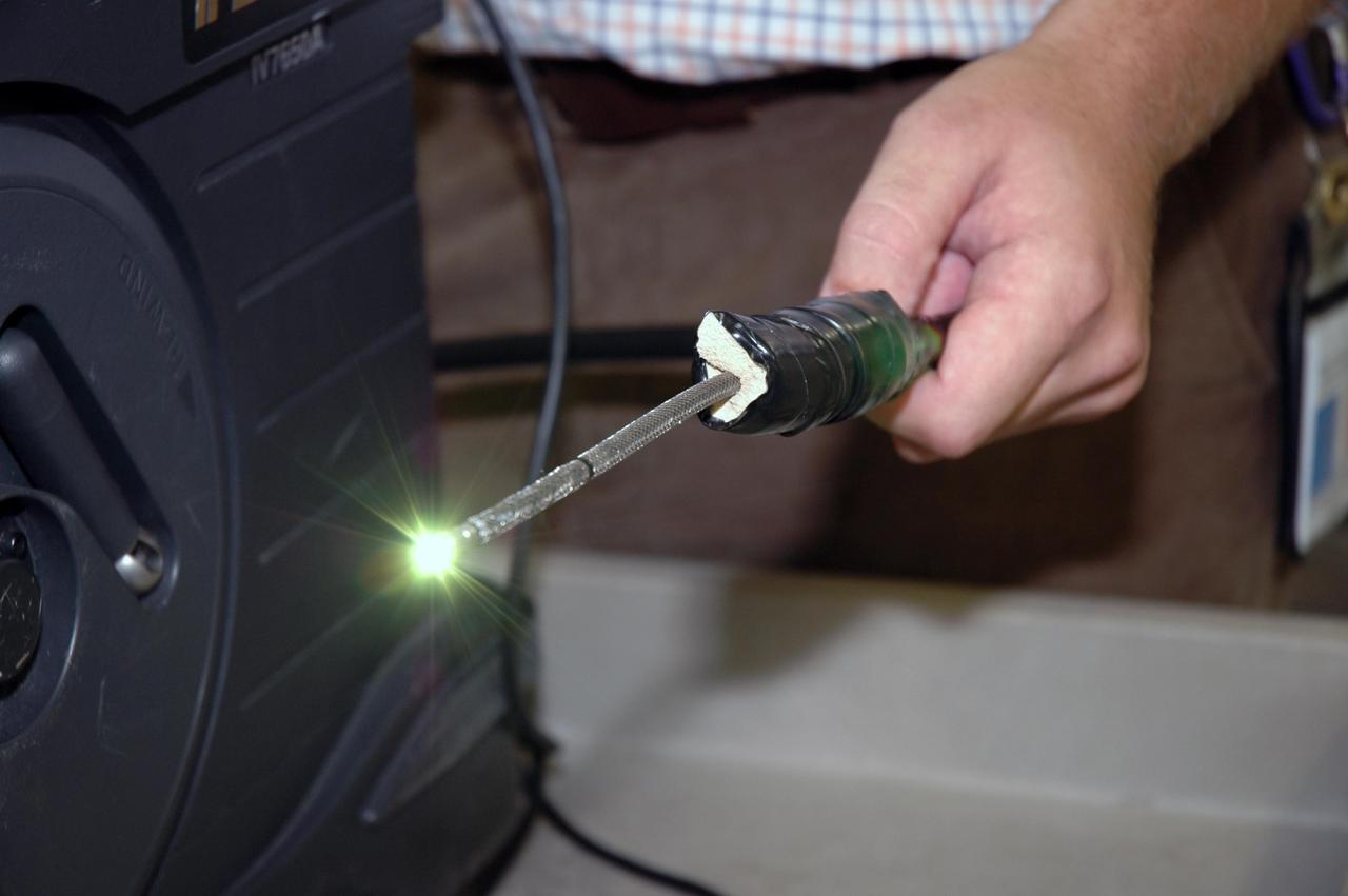
KENNEDY SPACE CENTER, FLA. - In the Press Site at NASA's Kennedy Space Center, Charles Wassen, with the United Space Alliance Micro Inspection Team, holds the boroscope camera probe, with the light glowing, that was used to verify the condition of the foam on Space Shuttle Discovery's external tank. On July 2, a crack formed on a piece of insulation on a strut that attaches the liquid oxygen feedline to External Tank-119, being used to launch space shuttle mission STS-121. It was recovered by the Ice Team from the mobile launch platform at Pad 39B. The camera was used to get a closeup of the area for the mission management team to examine and evaluate if the launch attempt should proceed on July 4. Photo credit: NASA/Carl Winebarger
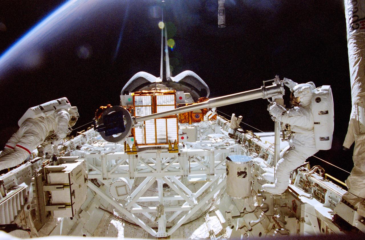
STS087-341-036 (3 Dec. 1997) --- Backdropped against a dark Earth and a light blue horizon, astronaut Takao Doi (right), international mission specialist representing Japan's National Space Development Agency (NASDA), works with a crane while astronaut Winston E. Scott looks on. This second extravehicular activity (EVA) of the mission continued the evaluation of techniques and hardware to be used in constructing the International Space Station (ISS). Near Scott can be seen the representation of a small Orbital Replacement Unit (ORU) in the grasp of the 156-pound crane operated by Doi. A similar crane could be used to transport various sized ORU’s from translation carts on the exterior of the ISS to various worksites on the truss structure. This view was captured, on 35mm film, by a crew mate in the shirt sleeve environment of the Space Shuttle Columbia's cabin. The SPARTAN-201 satellite is in its stowed position at frame center.
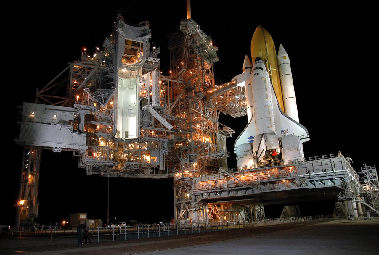
KENNEDY SPACE CENTER, FLA. -- The xenon lights on Launch Pad 39B illuminate Space Shuttle Discovery following the rollback of the Rotating Service Structure. A propellant-loading test of Discovery's External Tank (ET) is scheduled for April 14. During the test, the tank will be filled to launch levels with ultra-cold hydrogen and oxygen propellants, known as 'cryogenics.' The test is designed to evaluate how the tank, orbiter, Solid Rocket Boosters and ground systems are performing under full 'cryo-load.' Throughout testing, engineers will observe the effectiveness of key safety modifications made to the External Tank. NASA’s Return to Flight mission, STS-114 on Space Shuttle Discovery, is targeted for launch on May 15 with a launch window that extends to June 3.
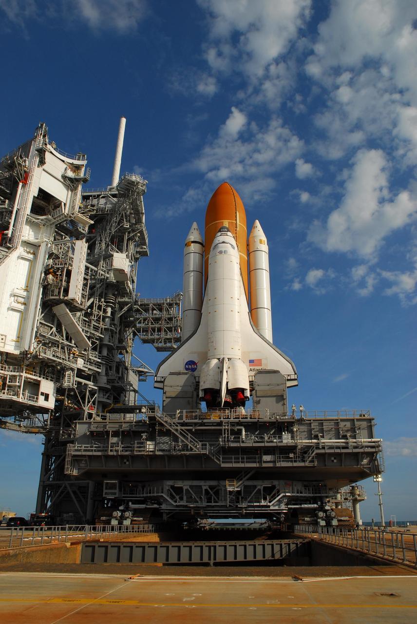
KENNEDY SPACE CENTER, FLA. -- In the early morning light on Launch Pad 39A, Space Shuttle Atlantis is revealed after rollback of the rotating service structure (at left). The shuttle is being rolled back to the Vehicle Assembly Building where it will be examined for hail damage. A severe thunderstorm with golf ball-sized hail caused divots in the giant tank's foam insulation and minor surface damage to about 26 heat shield tiles on the shuttle's left wing. Further evaluation of the tank is necessary to get an accurate accounting of foam damage and determine the type of repair required and the time needed for that work. A new target launch date has not been determined, but teams will focus on preparing Atlantis for liftoff in late April. Photo credit: NASA/Amanda Diller

Adolph Spakowski, head of the Photovoltaic Fundamentals Section at the National Aeronautics and Space Administration (NASA) Lewis Research Center, illustrated the difference between conventional silicon solar cells (rear panel) and the new thin-film cells. The larger, flexible thin-film cells in the foreground were evaluated by Lewis energy conversion specialists for possible future space use. The conventional solar cells used on most spacecraft at the time were both delicate and heavy. For example, the Mariner IV spacecraft required 28,000 these solar cells for its flyby of Mars in 1964. NASA Lewis began investigating cadmium sulfide thin-film solar cells in 1961. The thin-film cells were made by heating semiconductor material until it evaporated. The vapor was then condensed onto an electricity-producing film only one-thousandth of an inch thick. The physical flexibility of the new thin-film cells allowed them to be furled, or rolled up, during launch. Spakowski led an 18-month test program at Lewis to investigate the application of cadmium sulfide semiconductors on a light metallized substrate. The new thin-film solar cells were tested in a space simulation chamber at a simulated altitude of 200 miles. Sunlight was recreated by a 5000-watt xenon light. Two dozen cells were exposed to 15 minutes of light followed by 15 minutes of darkness to test their durability in the constantly changing illumination of Earth orbit.

NASA acquired November 24, 2011 From its vantage 824 kilometers (512 miles) above Earth, the Visible Infrared Imager Radiometer Suite (VIIRS) on the NPOESS Preparatory Project (NPP) satellite gets a complete view of our planet every day. This image from November 24, 2011, is the first complete global image from VIIRS. The NPP satellite launched on October 28, 2011, and VIIRS acquired its first measurements on November 21. To date, the images are preliminary, used to gauge the health of the sensor as engineers continue to power it up for full operation. Rising from the south and setting in the north on the daylight side of Earth, VIIRS images the surface in long wedges measuring 3,000 kilometers (1,900 miles) across. The swaths from each successive orbit overlap one another, so that at the end of the day, the sensor has a complete view of the globe. The Arctic is missing because it is too dark to view in visible light during the winter. The NPP satellite was placed in a Sun-synchronous orbit, a unique path that takes the satellite over the equator at the same local (ground) time in every orbit. So, when NPP flies over Kenya, it is about 1:30 p.m. on the ground. When NPP reaches Gabon—about 3,000 kilometers to the west—on the next orbit, it is close to 1:30 p.m. on the ground. This orbit allows the satellite to maintain the same angle between the Earth and the Sun so that all images have similar lighting. The consistent lighting is evident in the daily global image. Stripes of sunlight (sunglint) reflect off the ocean in the same place on the left side of every swath. The consistent angle is important because it allows scientists to compare images from year to year without worrying about extreme changes in shadows and lighting. The image also shows a band of haze along the right side of every orbit swath. When light travels through the atmosphere, it bounces off particles or scatters, making the atmosphere look hazy. The scattering effect is most pronounced along the edge of the swath, where the sensor is looking at an angle through more of the atmosphere. Scientists can correct for this scattering effect, but need measurements from a range of wavelengths to do so. The degree to which light scatters depends partly on the wavelength of the light. Blue light scatters more than red light, for example, which is why the sky is blue. VIIRS measures 22 different wavelengths of light, but not all of the sensor’s detectors are operating at peak performance yet. Those measuring thermal infrared light are not yet cold enough to collect reliable measurements. Once VIIRS begins full operations, it will produce a range of measurements from ocean temperature to clouds to the locations of fires. These measurements will help extend the record from earlier sensors like the Moderate Resolution Imaging Spectroradiometer (MODIS). VIIRS is very similar to MODIS, but flies at a higher altitude to measure the whole planet without gaps. (MODIS daily measurements have gaps at the equator. See the MODIS image from November 24.) VIIRS also sees the Earth in less detail, 375 meters per pixel, compared to 250 meters per pixel for MODIS. Image by NASA’s NPP Land Product Evaluation and Testing Element. Caption by Holli Riebeek. Credit: <b><a href="http://www.earthobservatory.nasa.gov/" rel="nofollow"> NASA Earth Observatory</a></b> <b><a href="http://www.nasa.gov/audience/formedia/features/MP_Photo_Guidelines.html" rel="nofollow">NASA image use policy.</a></b> <b><a href="http://www.nasa.gov/centers/goddard/home/index.html" rel="nofollow">NASA Goddard Space Flight Center</a></b> enables NASA’s mission through four scientific endeavors: Earth Science, Heliophysics, Solar System Exploration, and Astrophysics. Goddard plays a leading role in NASA’s accomplishments by contributing compelling scientific knowledge to advance the Agency’s mission. <b>Follow us on <a href="http://twitter.com/NASA_GoddardPix" rel="nofollow">Twitter</a></b> <b>Like us on <a href="http://www.facebook.com/pages/Greenbelt-MD/NASA-Goddard/395013845897?ref=tsd" rel="nofollow">Facebook</a></b> <b>Find us on <a href="http://instagrid.me/nasagoddard/?vm=grid" rel="nofollow">Instagram</a></b>
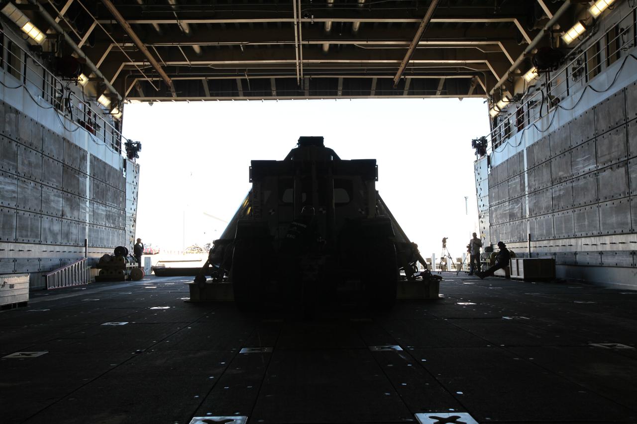
A contract of light and shadow. The test version of the Orion crew module has been transported into the well deck of the USS San Diego at Naval Base San Diego in California, as viewed from inside the ship. NASA, Orion manufacturer Lockheed Martin and the U.S. Navy will head out to sea with the Orion test spacecraft aboard for Underway Recovery Test 5 (URT-5) in the Pacific Ocean off the coast of California. During URT-5, the team will demonstrate and evaluate the recovery processes, procedures, hardware and personnel necessary for recovery of Orion on its return from a deep space mission. Orion is the exploration spacecraft designed to carry astronauts to destinations not yet explored by humans, including an asteroid and NASA Journey to Mars. It will have emergency abort capability, sustain the crew during space travel and provide safe re-entry from deep space return velocities. Orion is scheduled to launch atop NASA’s Space Launch System rocket in 2018. For more information, visit http://www.nasa.gov/orion.
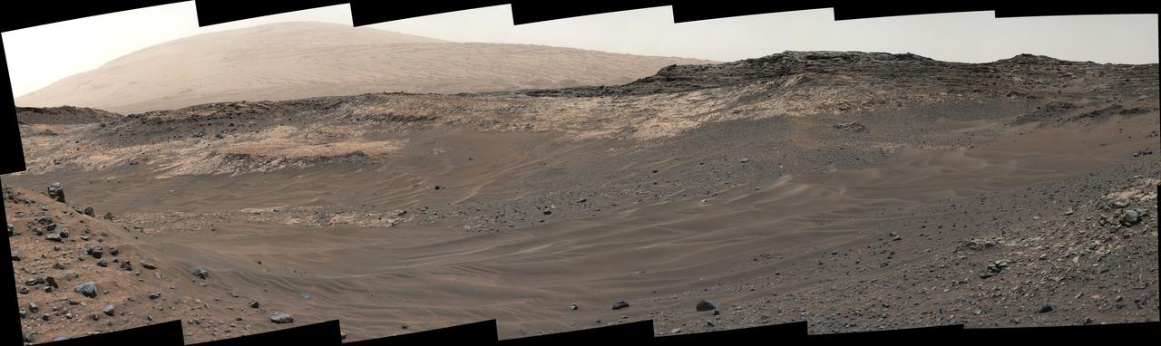
This view southeastward from Curiosity's Mast Camera (Mastcam) shows terrain judged difficult for traversing between the rover and an outcrop in the middle distance where a pale rock unit meets a darker rock unit above it. The Mastcam's left-eye camera captured the component images on May 10, 2015, during the 981st Martian day, or sol, of Curiosity's work on Mars. This observation helped the rover team evaluate routes for driving to that geological contact area where the two rock units meet. The outcrop exposing the contact is in the eastern portion of the "Logan Pass" area. The windblown ripples and the steep ground where ripples are lacking are both poor terrain for the rover to cross. The team subsequently chose to approach a different site where the pale and darker rock units are in contact with each other. That alternative site is in the northern portion of the Logan Pass area, outside of this scene. This panorama spans from east, at left, to south-southwest. The color has been approximately white-balanced to resemble how the scene would appear under daytime lighting conditions on Earth. http://photojournal.jpl.nasa.gov/catalog/PIA19662
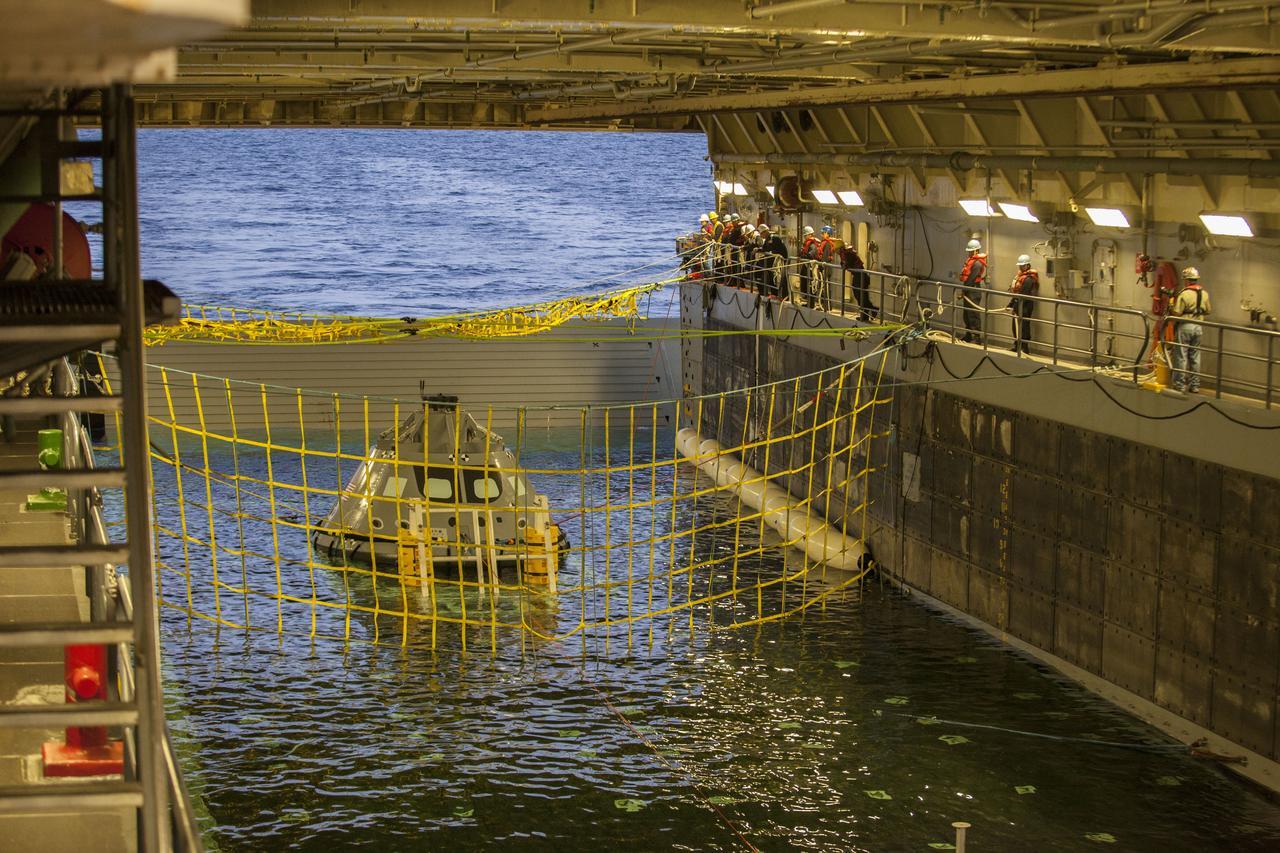
A golden sheen lights up a test version of the Orion crew module in the flooded well deck of the USS San Diego during Underway Recovery Test 5 in the Pacific Ocean off the coast of California. Recovery team personnel have secured a net around the crew module. NASA's Ground Systems Development and Operations Program and the U.S. Navy will conduct a series of tests to prepare for recovery of Orion on its return from deep space missions. The testing will allow the team to demonstrate and evaluate recovery processes, procedures, hardware and personnel in open waters. Orion is the exploration spacecraft designed to carry astronauts to destinations not yet explored by humans, including an asteroid and NASA's Journey to Mars. It will have emergency abort capability, sustain the crew during space travel and provide safe re-entry from deep space return velocities. Orion is scheduled to launch on NASA's Space Launch System in late 2018. For more information, visit http://www.nasa.gov/orion.
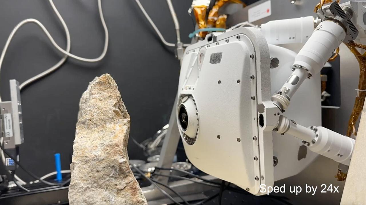
This time-lapse video, which has been sped up by 24 times, uses an engineering model of one of the instruments aboard NASA's Perseverance Mars rover to show how the instrument evaluates safe placement against a rock. If it's determined to be safe, the rover places the instrument, called the Planetary Instrument for X-ray Lithochemistry (PIXL), close to the targeted rock for science observations. This test occurred at NASA's Jet Propulsion Laboratory in Southern California on June 8, 2023. Located on the end of Perseverance's robotic arm, PIXL scans postage stamp-size areas on rocks with an X-ray beam the width of a human hair, determining which elements are present. Scientists use this information to infer what minerals and chemicals are in a rock and help decide whether Perseverance should collect a rock core using its drill. The X-ray beam exits the circular opening at the center of PIXL; colored LED lights around that circle can light up a surface, allowing an internal camera to take images. Those images allow PIXL to autonomously place itself – very slowly and precisely – as little as 1 inch (2.5 centimeters) away from a surface to collect its data. A key objective for Perseverance's mission on Mars is astrobiology, including the search for signs of ancient microbial life. The rover will characterize the planet's geology and past climate, pave the way for human exploration of the Red Planet, and be the first mission to collect and cache Martian rock and regolith (broken rock and dust). Subsequent NASA missions, in cooperation with ESA (European Space Agency), would send spacecraft to Mars to collect these sealed samples from the surface and return them to Earth for in-depth analysis. The Mars 2020 Perseverance mission is part of NASA's Moon to Mars exploration approach, which includes Artemis missions to the Moon that will help prepare for human exploration of the Red Planet. Animation available at https://photojournal.jpl.nasa.gov/catalog/PIA26204

These two radar images show the majestic Yellowstone National Park, Wyoming, the oldest national park in the United States and home to the world's most spectacular geysers and hot springs. The region supports large populations of grizzly bears, elk and bison. In 1988, the park was burned by one of the most widespread fires to occur in the northern Rocky Mountains in the last 50 years. Surveys indicated that 793,880 acres of land burned. Of that, 41 percent was burned forest, with tree canopies totally consumed by the fire; 35 percent was a combination of unburned, scorched and blackened trees; 13 percent was surface burn under an unburned canopy; 6 percent was non-forest burn; and 5 percent was undifferentiated burn. Six years later, the burned areas are still clearly visible in these false-color radar images obtained by the Spaceborne Imaging Radar-C/X-band Synthetic Aperture Radar on board the space shuttle Endeavour. The image at the left was obtained using the L-band radar channel, horizontally received and vertically transmitted, on the shuttle's 39th orbit on October 2, 1994. The area shown is 45 kilometers by 71 kilometers (28 miles by 44 miles) in size and centered at 44.6 degrees north latitude, 110.7 degrees west longitude. North is toward the top of the image (to the right). Most trees in this area are lodge pole pines at different stages of fire succession. Yellowstone Lake appears as a large dark feature at the bottom of the scene. At right is a map of the forest crown, showing its biomass, or amount of vegetation, which includes foliage and branches. The map was created by inverting SIR-C data and using in situ estimates of crown biomass gathered by the Yellowstone National Biological Survey. The map is displayed on a color scale from blue (rivers and lakes with no biomass) to brown (non-forest areas with crown biomass of less than 4 tons per hectare) to light brown (areas of canopy burn with biomass of between 4 and 12 tons per hectare). Yellow indicates areas of canopy burn and mixed burn with a biomass of between 12 to 20 tons per hectare; light green is mixed burn and on-burn forest with a biomass of 20 to 35 tons per hectare; and green is non-burned forest with a biomass of greater than 35 tons per hectare. Forest recovery from the fire seems to depend on fire intensity and soil conditions. In areas of severe canopy burn and poor soil conditions, crown biomass was still low in 1994 (indicated by the brown areas at the center left), whereas in areas of mixed burn with nutrient-rich soils, seen west of Yellowstone Lake, crown biomass has increased significantly in six years (indicated by the yellow and light green areas). Imaging fire-affected regions with spaceborne radar illustrates SIR-C/X-SAR's keen abilities to monitor regrowth after a fire. Knowing the amount of carbon accumulated in the atmosphere by regenerating forest in the 20 to 50 years following a fire disturbance is also a significant factor in understanding the global carbon cycle. Measuring crown biomass is necessary to evaluate the effects of past and future fires in specific regions. http://photojournal.jpl.nasa.gov/catalog/PIA01741
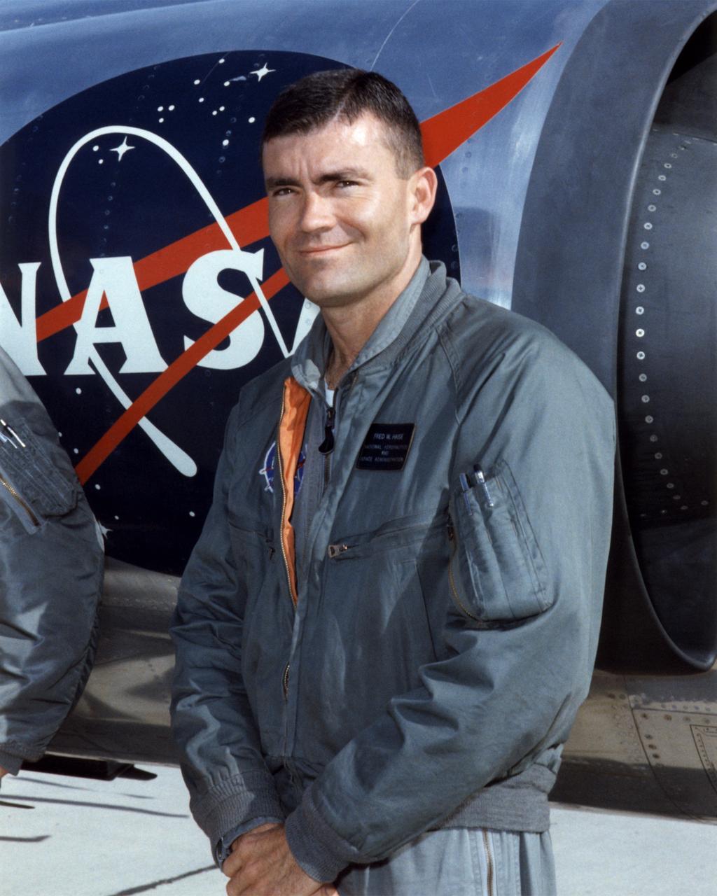
Fred W. Haise Jr. was a research pilot and an astronaut for the National Aeronautics and Space Administration from 1959 to 1979. He began flying at the Lewis Research Center in Cleveland, Ohio (today the Glenn Research Center), in 1959. He became a research pilot at the NASA Flight Research Center (FRC), Edwards, Calif., in 1963, serving NASA in that position for three years until being selected to be an astronaut in 1966 His best-known assignment at the FRC (later redesignated the Dryden Flight Research Center) was as a lifting body pilot. Shortly after flying the M2-F1 on a car tow to about 25 feet on April 22, 1966, he was assigned as an astronaut to the Johnson Space Center in Houston, Texas. While at the FRC he had also flown a variety of other research and support aircraft, including the variable-stability T-33A to simulate the M2-F2 heavyweight lifting body, some light aircraft including the Piper PA-30 to evaluate their handling qualities, the Apache helicopter, the Aero Commander, the Cessna 310, the Douglas F5D, the Lockheed F-104 and T-33, the Cessna T-37, and the Douglas C-47. After becoming an astronaut, Haise served as a backup crewmember for the Apollo 8, 11, and 16 missions. He flew on the aborted Apollo 13 lunar mission in 1970, spending 142 hours and 54 minutes in space before returning safely to Earth. In 1977, he was the commander of three free flights of the Space Shuttle prototype Enterprise when it flew its Approach and Landing Tests at Edwards Air Force Base, Calif. Meanwhile, from April 1973 to January 1976, Haise served as the Technical Assistant to the Manager of the Space Shuttle Orbiter Project. In 1979, he left NASA to become the Vice President for Space Programs with the Grumman Aerospace Corporation. He then served as President of Grumman Technical Services, an operating division of Northrop Grumman Corporation, from January 1992 until his retirement. Haise was born in Biloxi, Miss., on November 14, 1933. He underwent flight traini

This annotated image of Mars' Jezero Crater depicts the route NASA's Perseverance rover will take during its first science campaign – as well as its path to the location of its second science campaign. The image was provided by the High Resolution Imaging Experiment (HiRISE) aboard NASA's Mars Reconnaissance orbiter. Perseverance's first science campaign sends the rover south and west of the Octavia E. Butler Landing Site to investigate and sample several of the deepest, and potentially oldest, accessible geologic units in Jezero Crater – the "Séítah" unit (which in Navajo language means "amidst the sand"), and the "Cratered Floor Fractured Rough." At the completion of the science campaign, Perseverance will return to the "Octavia E. Butler" landing site on its way north, then head west toward the location where its second science campaign will begin. The first science campaign (depicted with yellow hash marks) begins with the rover performing an arching drive southward from its landing site to Séítah-North (Séítah-N). At that point the rover will travel west a short distance to an overlook where it can view much of the Séítah unit. The "Séítah-N Overlook" could also become an area of scientific interest – with Perseverance performing a "toe dip" into the unit to collect remote-sensing measurements of geologic targets. Once its time at the Séítah-N Overlook is complete, Perseverance will head east, then south toward a spot where the science team can study the Crater Floor Fractured Rough in greater detail. The first core sample collected by the mission will also take place at this location. After Cratered Floor Fractured Rough, the Perseverance rover team will evaluate whether additional exploration (depicted with light-yellow hash marks) farther south – and then west – is warranted. Whether Perseverance travels beyond the Cratered Floor Fractured Rough during this first science campaign, the rover will eventually retrace its steps. As Perseverance passes the Octavia B. Butler landing site, the first science campaign will conclude. At that point, several months of travel lay ahead as Perseverance makes its way to "Three Forks," where the second science campaign will begin. From Three Forks, Perseverance can access geologic locations at the base of the ancient delta (the fan-shaped remains of the confluence of an ancient river and a lake), as well as ascend the delta by driving up a valley wall to the northwest. https://photojournal.jpl.nasa.gov/catalog/PIA24596
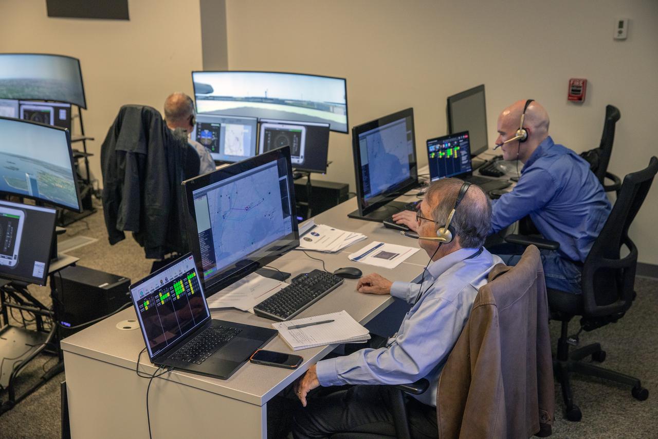
Focus on active photos –Class B Simulation Evaluation in the ATOL Lab at Langley (Also at FAA Tech Center) where team is working with one another in the lab, reviewing data on the monitors. Working the software, adjusting the software systems. Going over the shoulder to show the displays and screens as the software is running. John Foster (left) in the role of an air taxi pilot in the simulator chair with Jim Chamberlain and Terence McClain at the flight manager stations running virtual air taxi integration simulations focusing on urban air space at NASA’s Langley Research Center in Hampton, Virginia on Sept. 25, 2024.