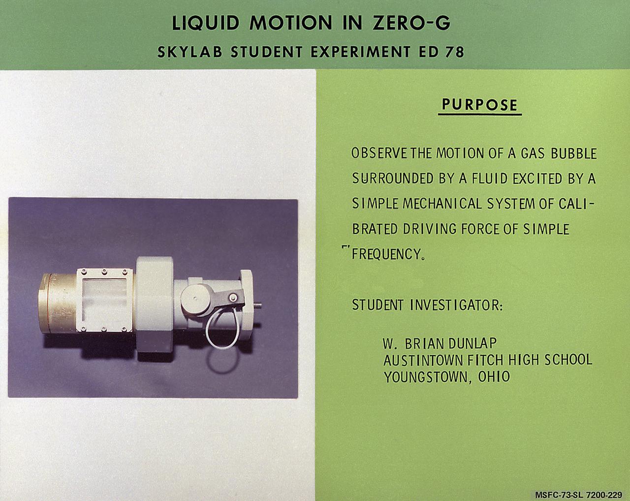
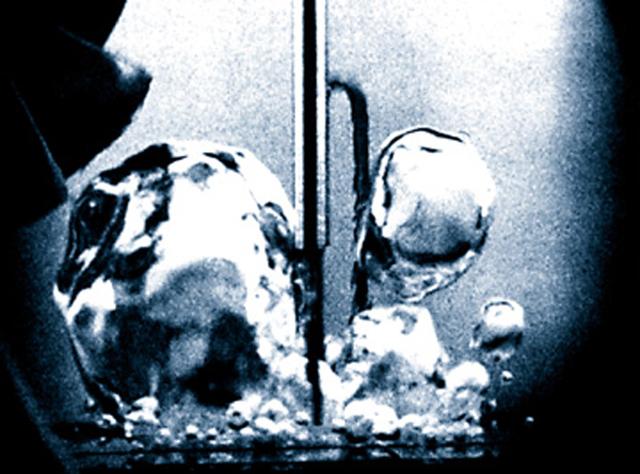
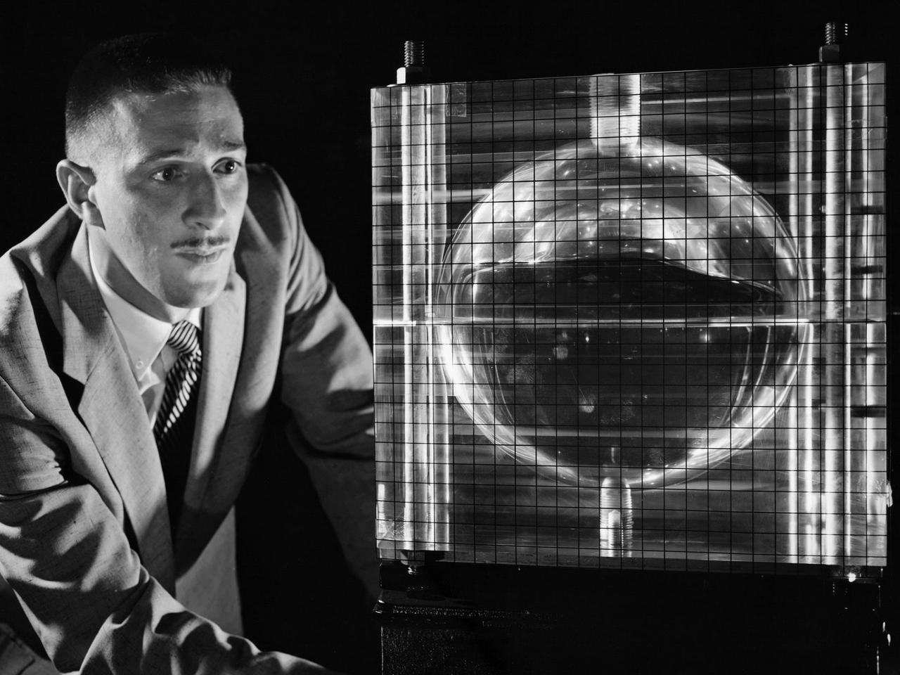
W. Brian Dunlap of Youngstown, Ohio, proposed Skylab student experiment ED-78, Liquid Motion in Zero-G, a study of wave motion in a liquid. He was particularly interested in comparing surface waves over a liquid in zero-gravity with those occurring on Earth. In space, with the absence of gravity, a liquid does not necessarily take the shape of its container as it does on Earth. Adhesion forces may hold the liquid in contact with its container, but the liquid can also assume a free-floating condition. It was in this latter state that Dunlap wished to examine the behavior of surface waves. Data were recorded on videotape and subsequently converted to 16-mm film. Dunlap analyzed these data to determine periods of oscillation of free-floating globules and found agreement with the theory to be much better than expected. In March 1972, NASA and the National Science Teachers Association selected 25 experiment proposals for flight on Skylab. Science advisors from the Marshall Space Flight Center aided and assisted the students in developing the proposals for flight on Skylab.
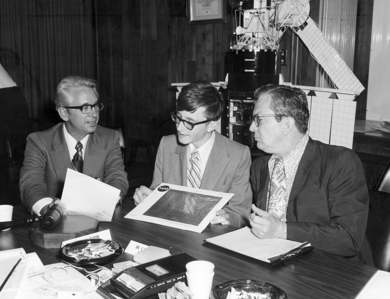
Youngstown, Ohio high school student, W. Brian Dunlap (center), discusses with Dr. Robert Head (right), and Henry Floyd, both of the Marshall Space Flight Center (MSFC), his experiment to be performed aboard the Skylab the following year. His experiment, “Wave Motion Trough A Liquid in Zero Gravity” used a container attached to the end of a leaf spring which was oscillated at specific rates using two thickness differentiated types of liquids. Dunlap was among 25 winners of a contest in which some 3,500 high school students proposed experiments for the following year’s Skylab mission. The nationwide scientific competition was sponsored by the National Science Teachers Association and the National Aeronautics and Space Administration (NASA). The winning students, along with their parents and sponsor teachers, visited MSFC where they met with scientists and engineers, participated in design reviews for their experiments, and toured MSFC facilities. Of the 25 students, 6 did not see their experiments conducted on Skylab because the experiments were not compatible with Skylab hardware and timelines. Of the 19 remaining, 11 experiments required the manufacture of additional equipment. The equipment for the experiments was manufactured at MSFC.
Fluid Physics is study of the motion of fluids and the effects of such motion. When a liquid is heated from the bottom to the boiling point in Earth's microgravity, small bubbles of heated gas form near the bottom of the container and are carried to the top of the liquid by gravity-driven convective flows. In the same setup in microgravity, the lack of convection and buoyancy allows the heated gas bubbles to grow larger and remain attached to the container's bottom for a significantly longer period.
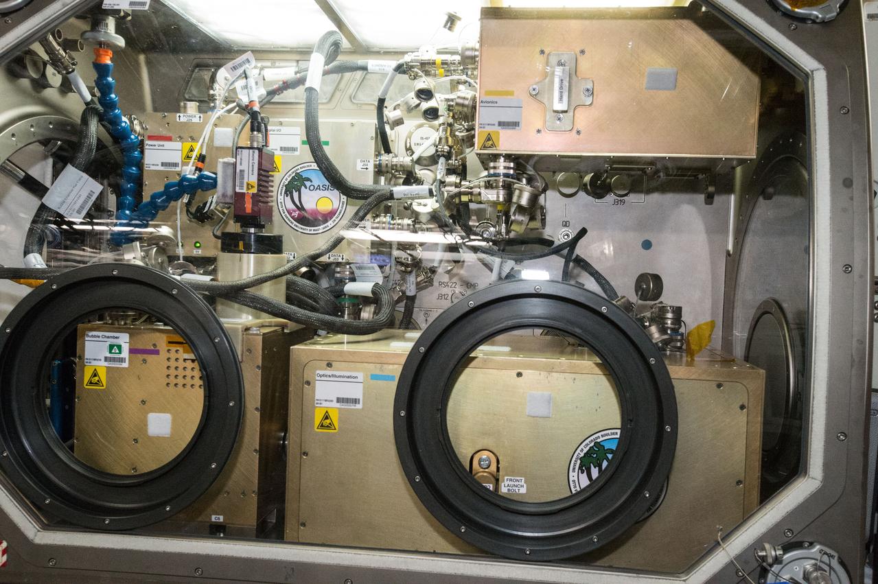
iss047e004376 (3/11/2016) --- A view during the installation and configuration of the Observation and Analysis of Smectic Islands in Space (OASIS) hardware into the Microgravity, in the U.S. Laboratory. OASIS studies the unique behavior of liquid crystals in microgravity, including their overall motion and the merging of crystal layers known as smectic islands. Liquid crystals are used for display screens in televisions and clocks and they also occur in soaps and in cell membranes. The experiment allows detailed studies of the behavior of these structures and how microgravity affects their unique ability to act like both a liquid and a solid crystal.
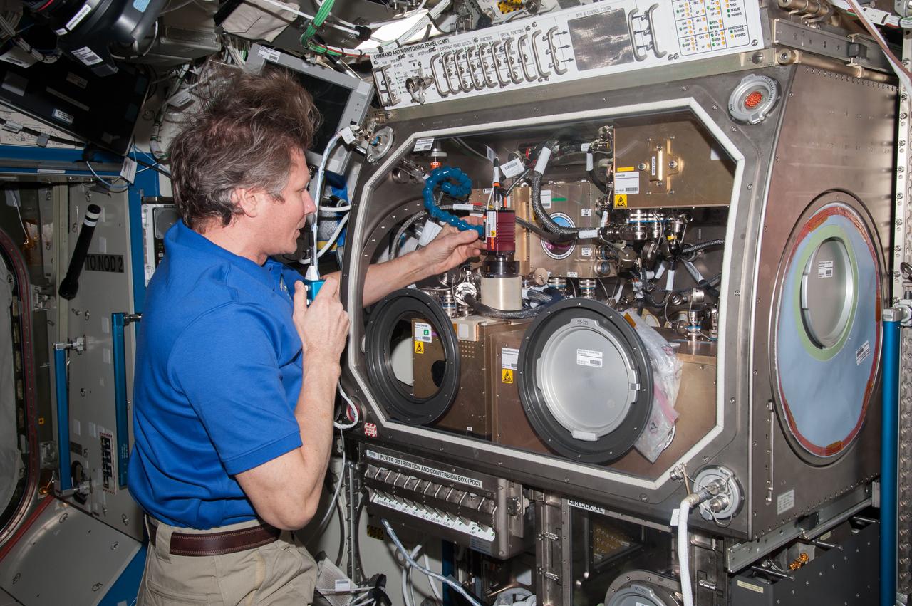
iss044e005118 (6/26/2015) --- Cosmonaut Gennady Padalka in the U.S. Laboratory in the process of aligning the Observation Analysis of Smectic Islands in Space (OASIS) Macro Camera. The Observation and Analysis of Smectic Islands In Space (OASIS) studies the unique behavior of liquid crystals in microgravity, including their overall motion and the merging of crystal layers known as smectic islands. Liquid crystals are used for display screens in televisions and clocks, and they also occur in soaps and in cell membranes. The experiment allows detailed studies of the behavior of these structures, and how microgravity affects their unique ability to act like both a liquid and a solid crystal.
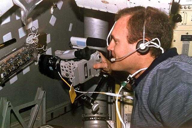
Astronaut James D. Halsell, Jr., mission commander, uses a Hi-8mm camcorder to videotape the Hand Held Diffusion Test Cells (HHDTC), in the Spacelab Science Module aboard the Earth-orbiting Space Shuttle Columbia (STS-94). Each test cell has three chambers containing a protein solution, a buffer solution and a precipitant solution chamber. Using the liquid-liquid diffusion method, the different fluids are brought into contact but not mixed. Over a period of time, the fluids will diffuse into each other through the random motion of molecules. The gradual increase in concentration of the precipitant within the protein solution causes the proteins to crystallize.
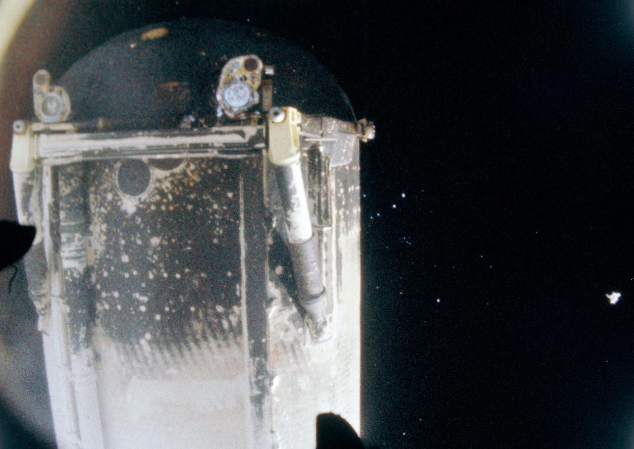
S81-30505 (12 April 1981) --- Separation of space shuttle Columbia?s external tank, photographed by motion picture cameras in the umbilical bays, occurred following the shutdown of the vehicle?s three main engines. Columbia?s cameras were able to record the bottom side of the tank as the orbiter headed toward its Earth-orbital mission with astronauts John W. Young and Robert L. Crippen aboard and the fuel tank fell toward Earth, passing through the atmosphere rapidly. Liquid oxygen and liquid hydrogen umbilical connectors can be seen at the bottom of the tank. For orientation, the photo should be held with the rounded end at bottom of the frame. Photo credit: NASA
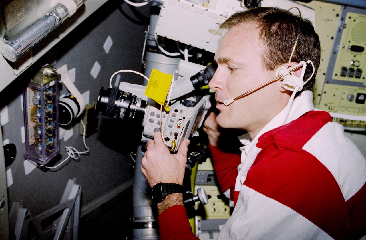
STS083-313-012 (4-8 April 1997) --- Astronaut James D. Halsell, Jr., mission commander, uses a Hi-8mm camcorder to videotape the Hand Held Diffusion Test Cells (HHDTC), in the Spacelab Module aboard the Earth-orbiting Space Shuttle Columbia. Each test cell has three chambers containing a protein solution, a buffer solution and a precipitant solution chamber. Using the liquid-liquid diffusion method, the different fluids are brought into contact but not mixed. Over a period of time, the fluids will diffuse into each other through the random motion of molecules. The gradual increase in concentration of the precipitant within the protein solution causes the proteins to crystallize.
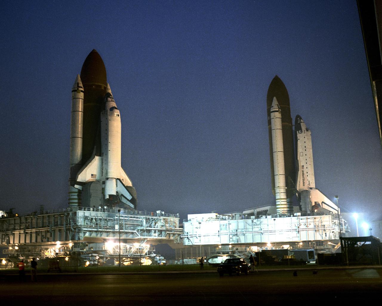
KENNEDY SPACE CENTER, FLA. -- The Space Shuttle Columbia (left), slated for mission STS-35, is rolled past the Space Shuttle Atlantis on its way to Pad 39A. Atlantis, slated for mission STS-38, is parked in front of bay three of the Vehicle Assembly Building following its rollback from Pad 39A for repairs to the liquid hydrogen lines. First motion of Atlantis from the pad was at 10:14 p.m. August 8. It arrived at the VAB at 4 a.m. August 9. First motion of Coumbia leaving the VAB for the pad was at 5:47 a.m. Columbia is due to arrive at the pad at noon August 9. Once Columbia is hard down at the pad, Atlantis will be moved into the VAB for destack operations. When Columbia reaches the pad, its payload bay doors will be opened and servicing of the ASTRO-1 payload will begin. Also, portions of the Shuttle interface verification test not completed in the VAB will be conducted.
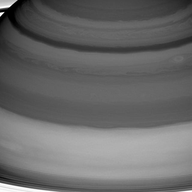
Saturn's clouds are full of raw beauty, but they also represent a playground for a branch of physics called fluid dynamics, which seeks to understand the motion of gases and liquids. Saturn's lack of a solid planetary surface (as on Earth, Mars or Venus) means that its atmosphere is free to flow around the planet essentially without obstruction. This is one factor that generates Saturn's pattern of alternating belts and zones -- one of the main features of its dynamic atmosphere. Winds in the belts blow at speeds different from those in the adjacent zones, leading to the formation of vortices along the boundaries between the two. And vigorous convection occasionally leads to storms and waves. Saturn's innermost rings are just visible at the bottom and in the upper left corner. This view is centered on clouds at 25 degrees north latitude on Saturn. The image was taken with the Cassini spacecraft wide-angle camera on July 20, 2016 using a spectral filter which preferentially admits wavelengths of near-infrared light centered at 728 nanometers. The view was obtained at a distance of approximately 752,000 miles (1.21 million kilometers) from Saturn and at a Sun-Saturn-spacecraft, or phase, angle of 6 degrees. Image scale is 45 miles (72 kilometers) per pixel. http://photojournal.jpl.nasa.gov/catalog/PIA20503

Atop the massive mobile launcher platform and crawler-transporter, Space Shuttle Atlantis begins rolling through the open door of the Vehicle Assembly Building for the journey to Launch Pad 39A. First motion was at 8:19 a.m. In front of each of Atlantis' wings are the tail masts, which provide several umbilical connections to the orbiter, including a liquid-oxygen line through one and a liquid-hydrogen line through another. The 3.4-mile trip to the pad along the crawlerway will take about 6 hours. The mission payload aboard Space Shuttle Atlantis is the S3/S4 integrated truss structure, along with a third set of solar arrays and batteries. The crew of six astronauts will install the truss to continue assembly of the International Space Station. Launch is targeted for March 15.
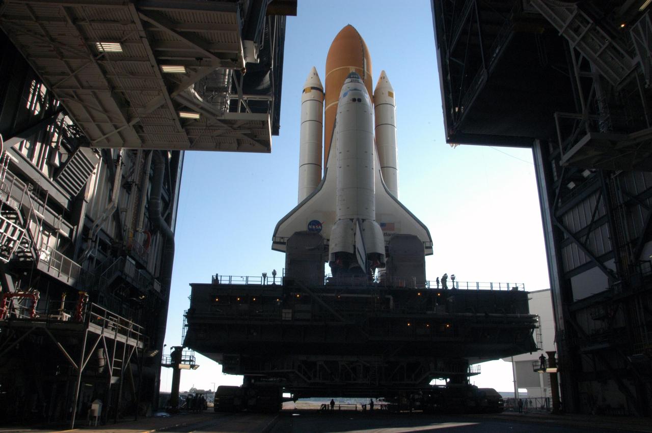
KENNEDY SPACE CENTER, FLA. -- Atop the massive mobile launcher platform and crawler-transporter, Space Shuttle Atlantis begins rolling through the open door of the Vehicle Assembly Building for the journey to Launch Pad 39A. First motion was at 8:19 a.m. In front of each of Atlantis' wings are the tail masts, which provide several umbilical connections to the orbiter, including a liquid-oxygen line through one and a liquid-hydrogen line through another. The 3.4-mile trip to the pad along the crawlerway will take about 6 hours. The mission payload aboard Space Shuttle Atlantis is the S3/S4 integrated truss structure, along with a third set of solar arrays and batteries. The crew of six astronauts will install the truss to continue assembly of the International Space Station. Launch is targeted for March 15. Photo credit: NASA/George Shelton
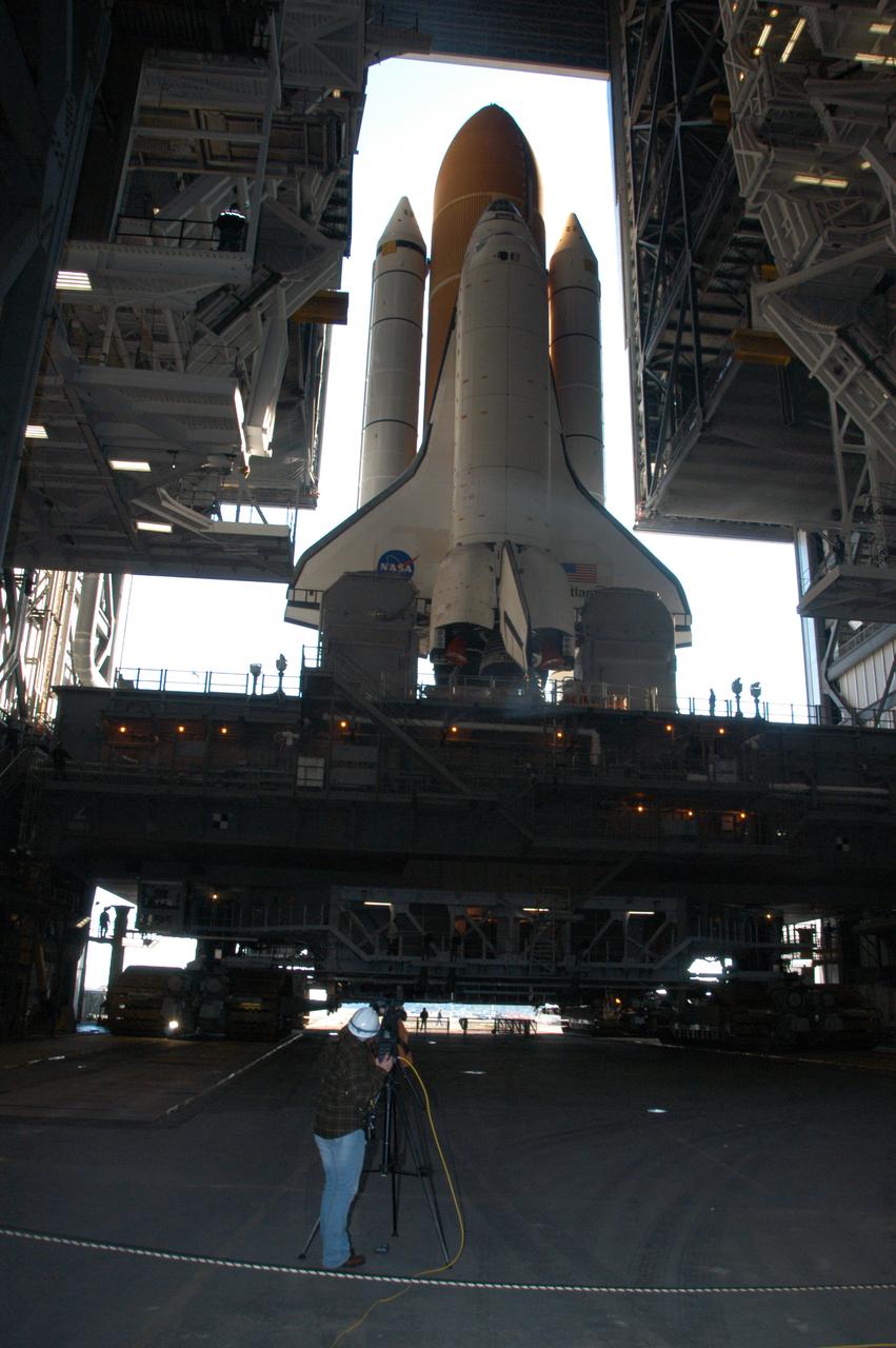
Andy Stofan views a small-scale tank built to study the sloshing characteristics of liquid hydrogen at the National Aeronautics and Space Administration (NASA) Lewis Research Center. Stofan was tasked with the study of propellant motion, or sloshing, in space vehicle propellant tanks. At the time, there was little knowledge of the behavior of fluids in microgravity or the effects of the launch on the propellant’s motion. Sloshing in the tank could alter a spacecraft’s trajectory or move the propellant away from the turbopump. Stofan became an expert and authored numerous technical reports on the subject. Stofan was assigned to the original Centaur Project Office in 1962 as a member of the Propellant Systems Section. Stofan was instrumental in solving a dynamic instability problem on the Centaur vehicle and served as the systems engineer for the development of the Centaur propellant utilization system. The solution was also applied to the upper-stages of Saturn. In 1966, Stofan was named Head of the Propellant Systems Section. Stofan continued rising through the managerial ranks at Lewis. In 1967 he became Project Manager of a test program that successfully demonstrated the use of a pressurization system for the Centaur vehicle; in 1969 the Assistant Project Manager on the Improved Centaur project; in 1970 Manager of the Titan/Centaur Project Office; in 1974 Director of the Launch Vehicles Division. In 1978, Stofan was appointed Deputy Associate Administrator for the Headquarters Office of Space Science. In 1982, he was named Director of Lewis Research Center.
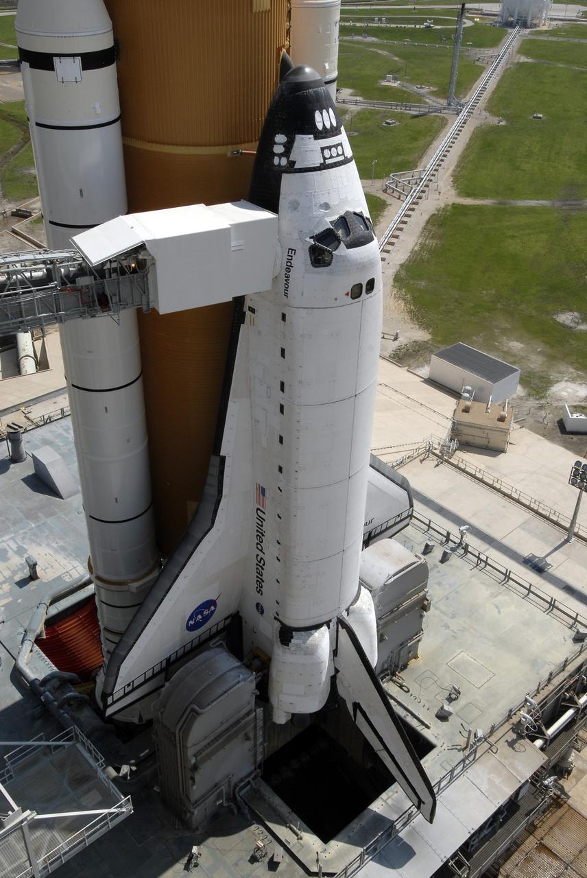
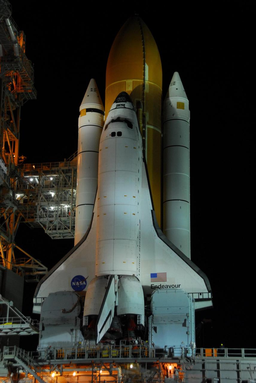
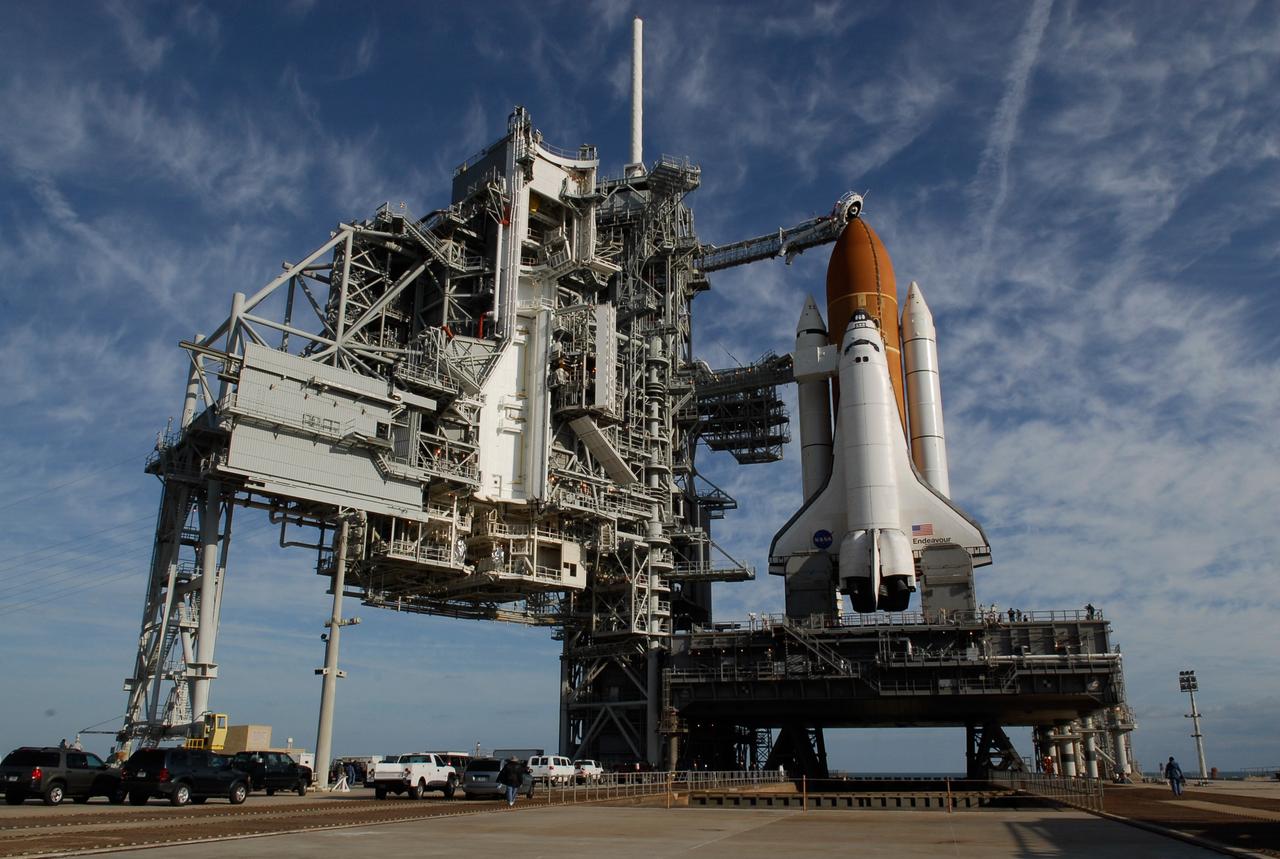
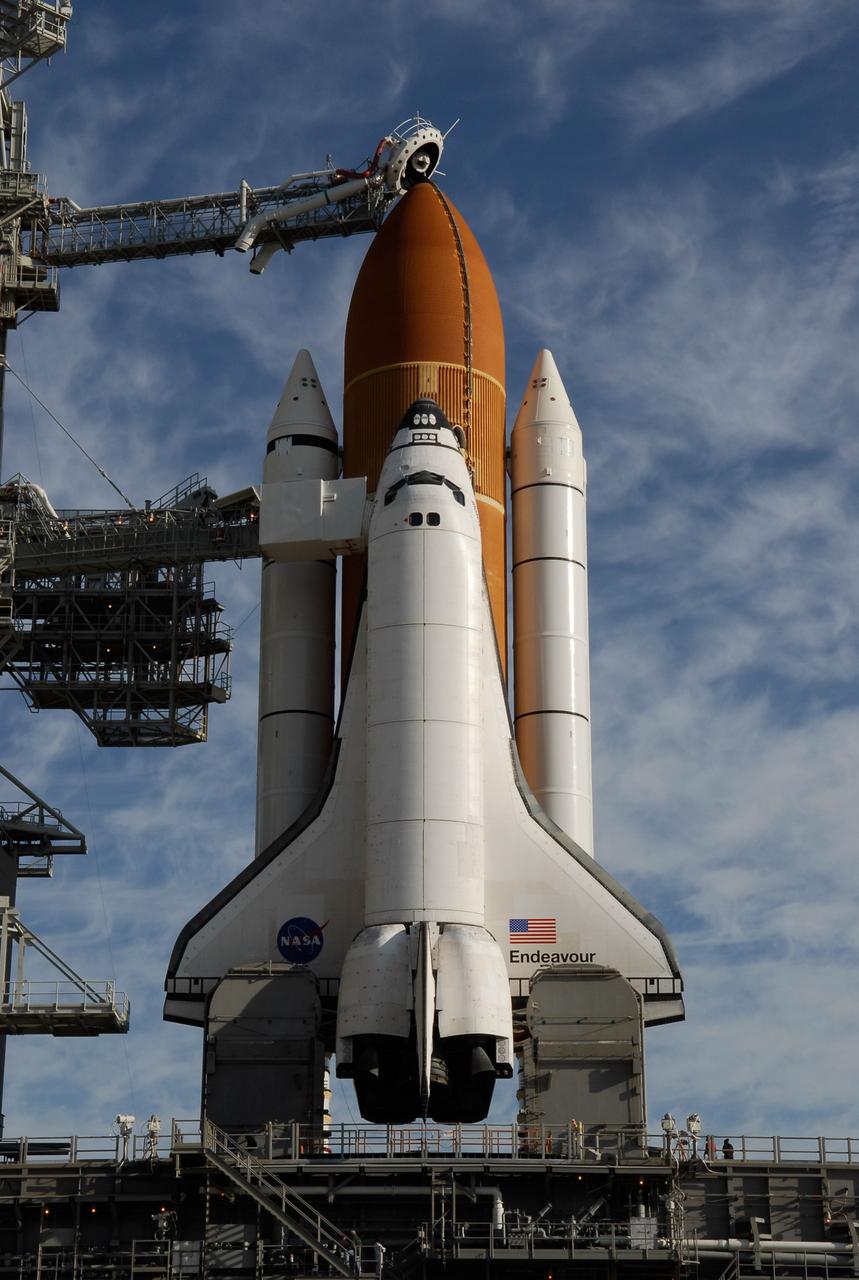
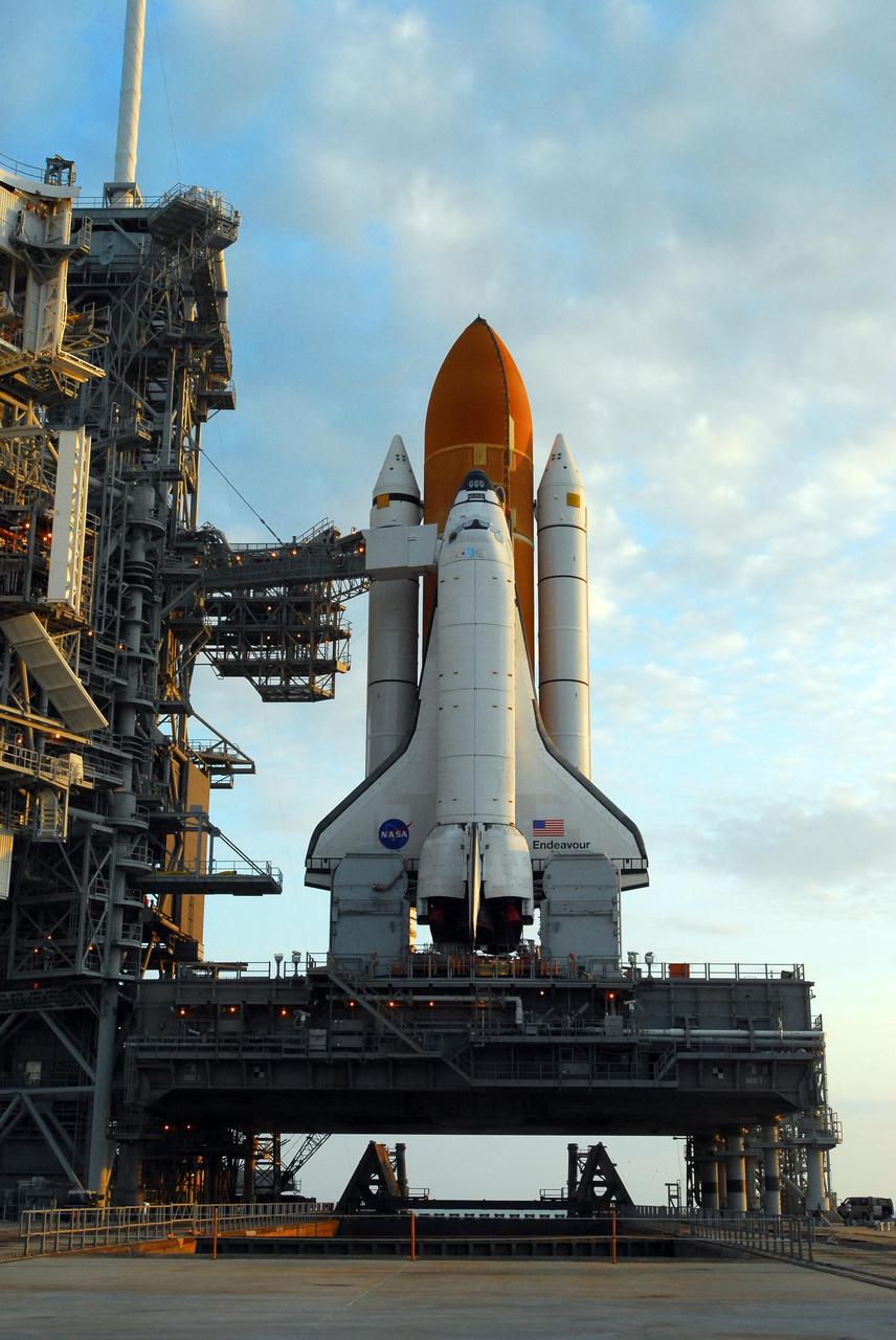
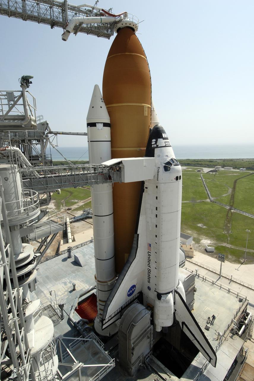
CAPE CANAVERAL, Fla. – After rollback of the rotating service structure, or RSS, on Launch Pad 39A at NASA's Kennedy Space Center in Florida, space shuttle Endeavour is closer to launch. Against Endeavour's cockpit is seen the White Room at the end of the orbiter access arm. The White Room provides the astronauts entry into the shuttle. Endeavour sits on the mobile launcher platform, which straddles the flame trench below. On either side of the engine nozzles are the tail masts, which provide several umbilical connections to the orbiter, including a liquid-oxygen line through one and a liquid-hydrogen line through another. First motion of the RSS was at 10:15 a.m. EDT. The rollback is in preparation for Endeavour's liftoff on the STS-127 mission with a crew of seven. This is the second launch attempt for Endeavour after the June 13 launch was scrubbed due to a hydrogen leak at the Ground Umbilical Carrier Plate during tanking June 12. The launch will be Endeavour's 23rd flight. The shuttle will carry the Japanese Experiment Module's Exposed Facility, or JEM-EF, and the Experiment Logistics Module-Exposed Section, or ELM-ES, on STS-127. The mission is the final of three flights dedicated to the assembly of the Japan Aerospace Exploration Agency's Kibo laboratory complex on the space station. Endeavour's launch is scheduled for June 17 at 5:40 a.m. EDT. Photo credit: NASA/Kim Shiflett
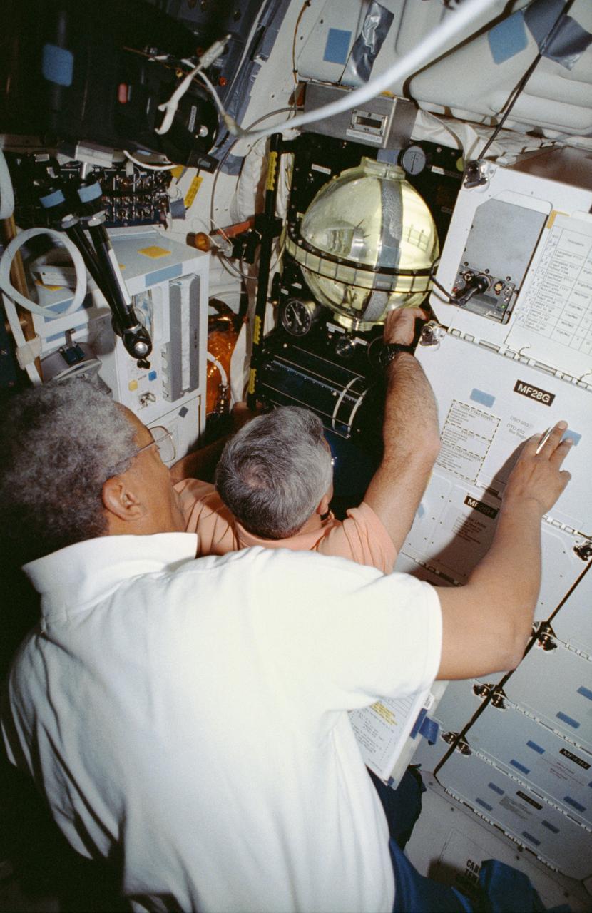
STS053-04-018 (2-9 Dec 1992) --- Astronauts Guion S. Bluford (left) and Michael R. U. (Rich) Clifford monitor the Fluid Acquisition and Resupply Equipment (FARE) onboard the Space Shuttle Discovery. Clearly visible in the mid-deck FARE setup is one of two 12.5-inch spherical tanks made of transparent acrylic, one to supply and one to receive fluids. The purpose of FARE is to investigate the dynamics of fluid transfer in microgravity and develop methods for transferring vapor-free propellants and other liquids that must be replenished in long-term space systems like satellites, Extended-Duration Orbiters (EDO), and Space Station Freedom. Eight times over an eight-hour test period, the mission specialists conducted the FARE experiment. A sequence of manual valve operations caused pressurized air from the bottles to force fluids from the supply tank to the receiver tank and back again to the supply tank. Baffles in the receiver tank controlled fluid motion during transfer, a fine-mesh screen filtered vapor from the fluid, and the overboard vent removed vapor from the receiver tank as the liquid rose. FARE is managed by NASA's Marshall Space Flight Center (MSFC) in Alabama. The basic equipment was developed by Martin Marietta for the Storable Fluid Management Demonstration. Susan L. Driscoll is the principal investigator.
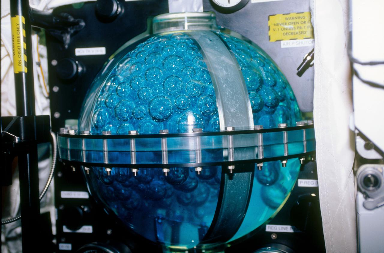
STS053-09-019 (2 - 9 Dec 1992) --- A medium close-up view of part of the Fluid Acquisition and Resupply Equipment (FARE) onboard the Space Shuttle Discovery. Featured in the mid-deck FARE setup is fluid activity in one of two 12.5-inch spherical tanks made of transparent acrylic. Pictured is the receiver tank. The other tank, out of frame below, is for supplying fluids. The purpose of FARE is to investigate the dynamics of fluid transfer in microgravity and develop methods for transferring vapor-free propellants and other liquids that must be replenished in long-term space systems like satellites, Extended-Duration Orbiters (EDO), and Space Station Freedom. Eight times over an eight-hour test period, the mission specialists conducted the FARE experiment. A sequence of manual valve operations caused pressurized air from the bottles to force fluids from the supply tank to the receiver tank and back again to the supply tank. Baffles in the receiver tank controlled fluid motion during transfer, a fine-mesh screen filtered vapor from the fluid, and the overboard vent removed vapor from the receiver tank as the liquid rose. FARE is managed by NASA's Marshall Space Flight Center (MSFC) in Alabama. The basic equipment was developed by Martin Marietta for the Storable Fluid Management Demonstration. Susan L. Driscoll is the principal investigator.

KENNEDY SPACE CENTER, FLA. -- Space Shuttle Atlantis, mounted on a mobile launch platform, finally rests on the hard stand of Launch Pad 39A after an early morning rollout. This is the second rollout for the shuttle. Seen on either side of the main engine exhaust hole on the launcher platform are the tail service masts. Their function is to provide umbilical connections for liquid oxygen and liquid hydrogen lines to fuel the external tank from storage tanks adjacent to the launch pad. Other umbilical lines carry helium and nitrogen, as well as ground electrical power and connections for vehicle data and communications. First motion out of the Vehicle Assembly Building was at 5:02 a.m. EDT. In late February, while Atlantis was on the launch pad, Atlantis' external tank received hail damage during a severe thunderstorm that passed through the Kennedy Space Center Launch Complex 39 area. The hail caused visible divots in the giant tank's foam insulation, as well as minor surface damage to about 26 heat shield tiles on the shuttle's left wing. The shuttle was returned to the VAB for repairs. The launch of Space Shuttle Atlantis on mission STS-117 is now targeted for June 8. A flight readiness review will be held on May 30 and 31. Photo credit: NASA/Troy Cryder
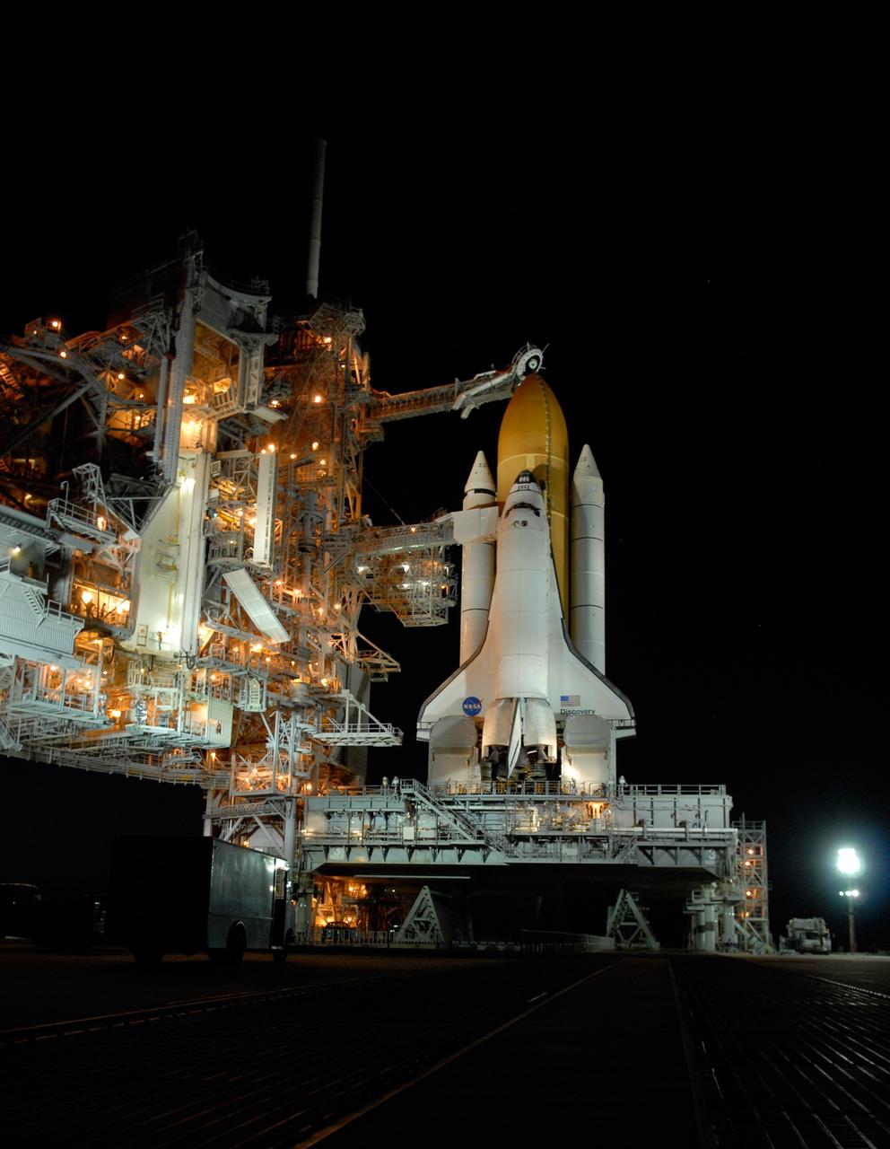
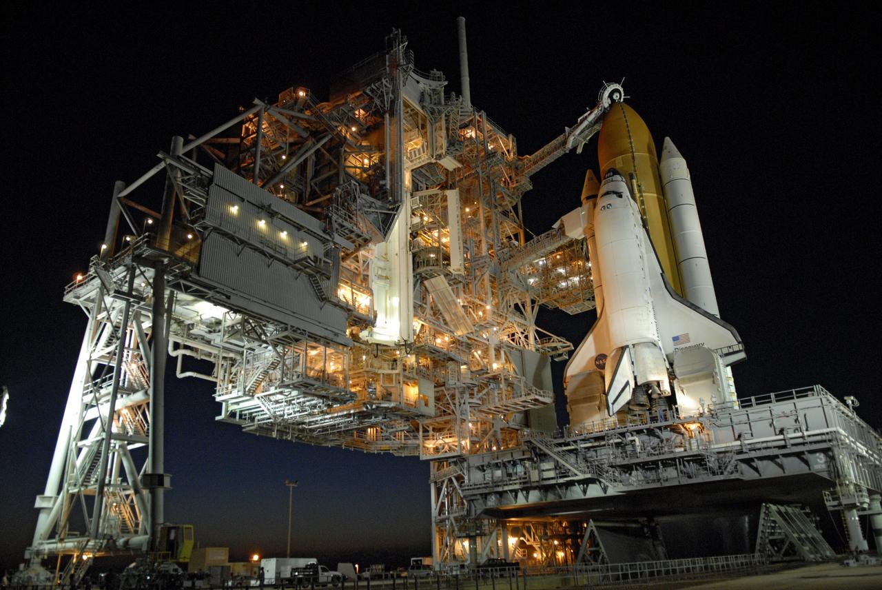
CAPE CANAVERAL, Fla. – Sitting on top of the mobile launcher platform, space shuttle Discovery arrives on top of Launch Pad 39A at NASA's Kennedy Space Center in Florida. Traveling from the Vehicle Assembly Building, the shuttle took nearly 12 hours on the journey as technicians stopped several times to clear mud from the crawler's treads and bearings caused by the waterlogged crawlerway. First motion out of the VAB was at 2:07 a.m. EDT Aug. 4. Rollout was delayed approximately 2 hours due to lightning in the area. In the foreground next to Discovery's main engines is one of the two tail masts, which provide several umbilical connections to the orbiter, including a liquid-oxygen line through one and a liquid-hydrogen line through another. Discovery's 13-day flight will deliver a new crew member and 33,000 pounds of equipment to the International Space Station. The equipment includes science and storage racks, a freezer to store research samples, a new sleeping compartment and the COLBERT treadmill. Launch of Discovery on its STS-128 mission is targeted for late August. Photo credit: NASA/Troy Cryder
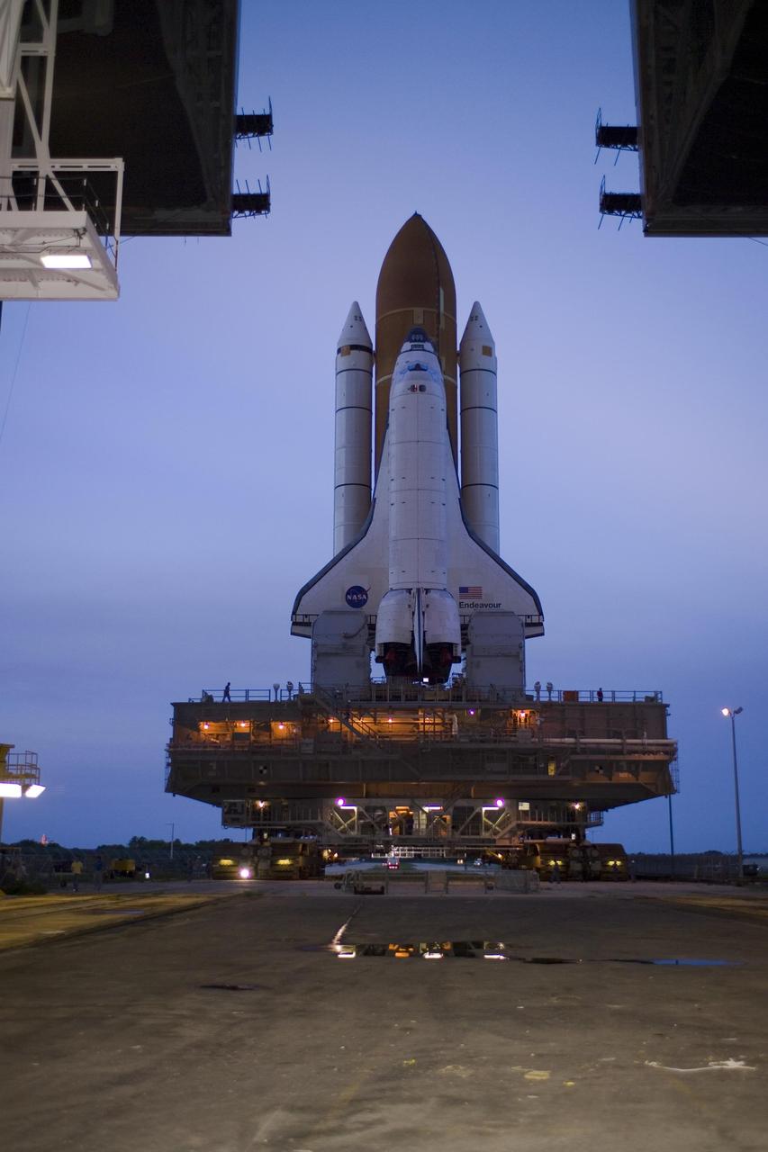
KENNEDY SPACE CENTER, FLA. -- At sunset, Space Shuttle Endeavour, atop the lighted mobile launcher platform, exits the Vehicle Assembly Building for rollout to Launch Pad 39A. First motion out of the VAB was at 8:10 p.m. July 10, and the shuttle was hard down on the pad at 3:02 a.m. July 11. Seen below the orbiter's wings and attached to the launcher platform are the tail masts, which provide several umbilical connections to the orbiter, including a liquid-oxygen line through one and a liquid-hydrogen line through another. The shuttle and platform are being carried by the crawler-transporter. The trip will take between six and eight hours. Endeavour is scheduled to launch on mission STS-118 on Aug. 7. During the mission, Endeavour will carry into orbit the S5 truss, SPACEHAB module and external stowage platform 3. The mission is the 22nd flight to the International Space Station and will mark the first flight of Mission Specialist Barbara Morgan, the teacher-turned-astronaut whose association with NASA began more than 20 years ago. STS-118 will be the first flight since 2002 for Endeavour, which has undergone extensive modifications, including the addition of safety upgrades already added to orbiters Discovery and Atlantis. Photo credit: NASA/Tom Farrar
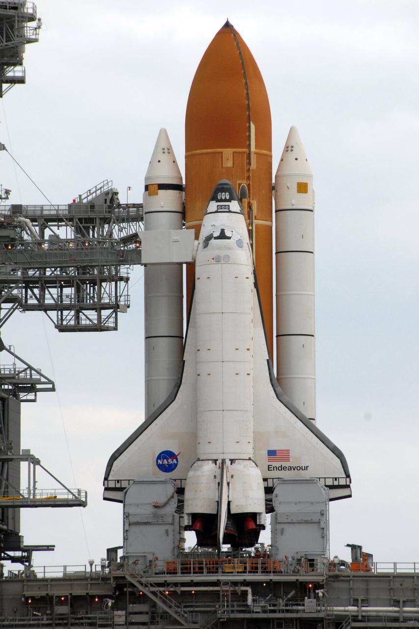
KENNEDY SPACE CENTER, FLA. - Space Shuttle Endeavour, atop the mobile launcher platform, is hard down on Launch Pad 39A after rolling out over night. First motion out of the Vehicle Assembly Building was at 8:10 p.m. July 10. The components of the shuttle are, first, the orbiter and then the solid rocket boosters flanking the external tank behind it. Attached to the platform and seen below the orbiter's wings are the tail masts, which provide several umbilical connections to the orbiter, including a liquid-oxygen line through one and a liquid-hydrogen line through another. Near the cockpit of Endeavour is the orbiter access arm, which provides access into the vehicle. Endeavour is scheduled to launch on mission STS-118 on Aug. 7. During the mission, Endeavour will carry into orbit the S5 truss, SPACEHAB module and external stowage platform 3. The mission is the 22nd flight to the International Space Station and will mark the first flight of Mission Specialist Barbara Morgan, the teacher-turned-astronaut whose association with NASA began more than 20 years ago. STS-118 will be the first flight since 2002 for Endeavour, which has undergone extensive modifications, including the addition of safety upgrades already added to orbiters Discovery and Atlantis. Photo credit: NASA/Ken Thornsley
KENNEDY SPACE CENTER, FLA. -- Near sunset, Space Shuttle Endeavour, atop the mobile launcher platform, begins moving through the doors of the Vehicle Assembly Building for rollout to Launch Pad 39A. First motion out of the VAB was at 8:10 p.m. July 10, and the shuttle was hard down on the pad at 3:02 a.m. July 11. Seen below the orbiter's wings and attached to the launcher platform are the tail masts, which provide several umbilical connections to the orbiter, including a liquid-oxygen line through one and a liquid-hydrogen line through another. Endeavour is scheduled to launch on mission STS-118 on Aug. 7. During the mission, Endeavour will carry into orbit the S5 truss, SPACEHAB module and external stowage platform 3. The mission is the 22nd flight to the International Space Station and will mark the first flight of Mission Specialist Barbara Morgan, the teacher-turned-astronaut whose association with NASA began more than 20 years ago. STS-118 will be the first flight since 2002 for Endeavour, which has undergone extensive modifications, including the addition of safety upgrades already added to orbiters Discovery and Atlantis. Photo credit: NASA/Tom Farrar
KENNEDY SPACE CENTER, FLA. -- After a nearly 7-hour trip, Space Shuttle Endeavour, atop the mobile launcher platform, is hard down on Launch Pad 39A at 3:02 a.m. First motion out of the Vehicle Assembly Building was at 8:10 p.m. July 10. The components of the shuttle are, first, the orbiter and then the solid rocket boosters flanking the external tank behind it. Seen below the orbiter's wings are the tail masts, which provide several umbilical connections to the orbiter, including a liquid-oxygen line through one and a liquid-hydrogen line through another. Endeavour is scheduled to launch on mission STS-118 on Aug. 7. During the mission, Endeavour will carry into orbit the S5 truss, SPACEHAB module and external stowage platform 3. The mission is the 22nd flight to the International Space Station and will mark the first flight of Mission Specialist Barbara Morgan, the teacher-turned-astronaut whose association with NASA began more than 20 years ago. STS-118 will be the first flight since 2002 for Endeavour, which has undergone extensive modifications, including the addition of safety upgrades already added to orbiters Discovery and Atlantis. Photo credit: NASA/George Shelton
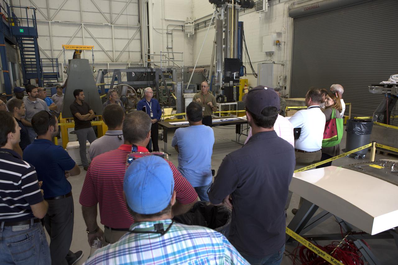
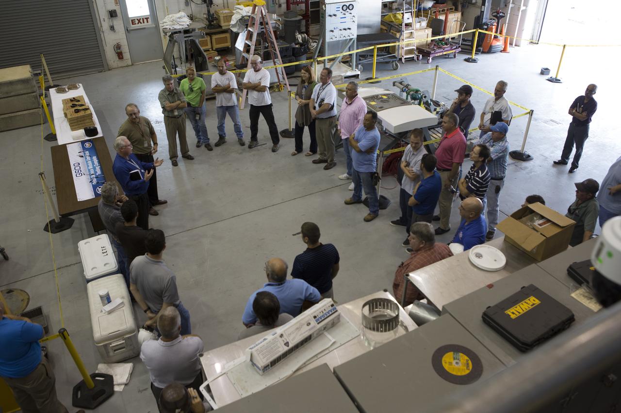
Testing of the Orion Service Module Umbilical (OSMU) was completed at the Launch Equipment Test Facility at NASA’s Kennedy Space Center in Florida. The OSMU was attached to Vehicle Motion Simulator 1 for a series of simulated launch tests to validate it for installation on the mobile launcher. Patrick Simpkins, director of Engineering, speaks to the test team during an event to mark the end of testing. The mobile launcher tower will be equipped with a number of lines, called umbilicals that will connect to the Space Launch System rocket and Orion spacecraft for Exploration Mission-1 (EM-1). The OSMU will be located high on the mobile launcher tower and, prior to launch, will transfer liquid coolant for the electronics and air for the Environmental Control System to the Orion service module that houses these critical systems to support the spacecraft. Kennedy's Engineering Directorate is providing support to the Ground Systems Development and Operations Program for testing of the OSMU. EM-1 is scheduled to launch in 2018.
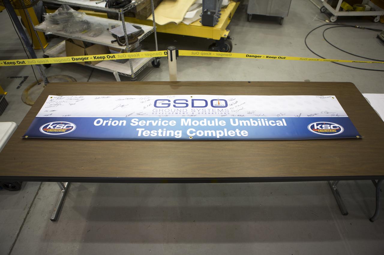
Testing of the Orion Service Module Umbilical (OSMU) was completed at the Launch Equipment Test Facility at NASA’s Kennedy Space Center in Florida. The OSMU was attached to Vehicle Motion Simulator 1 for a series of simulated launch tests to validate it for installation on the mobile launcher. The test team signed a special banner during an event to mark the end of testing. The mobile launcher tower will be equipped with a number of lines, called umbilicals that will connect to the Space Launch System rocket and Orion spacecraft for Exploration Mission-1 (EM-1). The OSMU will be located high on the mobile launcher tower and, prior to launch, will transfer liquid coolant for the electronics and air for the Environmental Control System to the Orion service module that houses these critical systems to support the spacecraft. Kennedy's Engineering Directorate is providing support to the Ground Systems Development and Operations Program for testing of the OSMU. EM-1 is scheduled to launch in 2018.
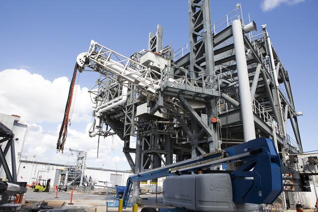
Testing of the Orion Service Module Umbilical (OSMU) was completed at the Launch Equipment Test Facility at NASA’s Kennedy Space Center in Florida. The OSMU was attached to Vehicle Motion Simulator 1 for a series of simulated launch tests to validate it for installation on the mobile launcher. The mobile launcher tower will be equipped with a number of lines, called umbilicals that will connect to the Space Launch System rocket and Orion spacecraft for Exploration Mission-1 (EM-1). The OSMU will be located high on the mobile launcher tower and, prior to launch, will transfer liquid coolant for the electronics and air for the Environmental Control System to the Orion service module that houses these critical systems to support the spacecraft. Kennedy's Engineering Directorate is providing support to the Ground Systems Development and Operations Program for testing of the OSMU. EM-1 is scheduled to launch in 2018.
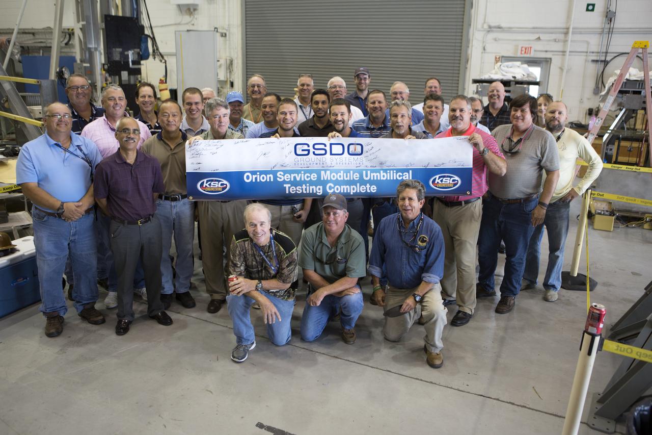
Testing of the Orion Service Module Umbilical (OSMU) was completed at the Launch Equipment Test Facility at NASA’s Kennedy Space Center in Florida. The OSMU was attached to Vehicle Motion Simulator 1 for a series of simulated launch tests to validate it for installation on the mobile launcher. The test team gathered with a special banner during an event to mark the end of testing. The mobile launcher tower will be equipped with a number of lines, called umbilicals that will connect to the Space Launch System rocket and Orion spacecraft for Exploration Mission-1 (EM-1). The OSMU will be located high on the mobile launcher tower and, prior to launch, will transfer liquid coolant for the electronics and air for the Environmental Control System to the Orion service module that houses these critical systems to support the spacecraft. Kennedy's Engineering Directorate is providing support to the Ground Systems Development and Operations Program for testing of the OSMU. EM-1 is scheduled to launch in 2018.

Testing of the Orion Service Module Umbilical (OSMU) was completed at the Launch Equipment Test Facility at NASA’s Kennedy Space Center in Florida. The OSMU was attached to Vehicle Motion Simulator 1 for a series of simulated launch tests to validate it for installation on the mobile launcher. One of the test team members signs a banner during an event to mark the end of testing. The mobile launcher tower will be equipped with a number of lines, called umbilicals that will connect to the Space Launch System rocket and Orion spacecraft for Exploration Mission-1 (EM-1). The OSMU will be located high on the mobile launcher tower and, prior to launch, will transfer liquid coolant for the electronics and air for the Environmental Control System to the Orion service module that houses these critical systems to support the spacecraft. Kennedy's Engineering Directorate is providing support to the Ground Systems Development and Operations Program for testing of the OSMU. EM-1 is scheduled to launch in 2018.
![ISS007-E-17842 (23 October 2003) --- European Space Agency (ESA) astronaut Pedro Duque (left) of Spain and cosmonaut Alexander Y. Kaleri, Expedition 8 flight engineer representing Rosaviakosmos, work with a scientific experiment in the Zvezda Service Module on the International Space Station (ISS). Duque and Kaleri performed the European educational VIDEO-2 (VID-01) experiment, which uses the Russian DSR PD-150P digital video camcorder for recording demos of several basic physical phenomena, viz., Isaac Newton's three motion laws, with narration. [The demo made use of a sealed bag containing coffee and a syringe to fill one of two hollow balls with the brown liquid (to provide "mass", as opposed to the other, "mass-less" ball).]](https://images-assets.nasa.gov/image/iss007e17842/iss007e17842~medium.jpg)
ISS007-E-17842 (23 October 2003) --- European Space Agency (ESA) astronaut Pedro Duque (left) of Spain and cosmonaut Alexander Y. Kaleri, Expedition 8 flight engineer representing Rosaviakosmos, work with a scientific experiment in the Zvezda Service Module on the International Space Station (ISS). Duque and Kaleri performed the European educational VIDEO-2 (VID-01) experiment, which uses the Russian DSR PD-150P digital video camcorder for recording demos of several basic physical phenomena, viz., Isaac Newton's three motion laws, with narration. [The demo made use of a sealed bag containing coffee and a syringe to fill one of two hollow balls with the brown liquid (to provide "mass", as opposed to the other, "mass-less" ball).]
![ISS007-E-17848 (23 October 2003) --- Cosmonaut Alexander Y. Kaleri (right), Expedition 8 flight engineer, uses a camera to film a scientific experiment performed by European Space Agency (ESA) astronaut Pedro Duque of Spain in the Zvezda Service Module on the International Space Station (ISS). Kaleri represents Rosaviakosmos. Duque and Kaleri performed the European educational VIDEO-2 (VID-01) experiment, which uses the Russian DSR PD-150P digital video camcorder for recording demos of several basic physical phenomena, viz., Isaac Newton's three motion laws, with narration. [The demo made use of a sealed bag containing coffee and a syringe to fill one of two hollow balls with the brown liquid (to provide "mass", as opposed to the other, "mass-less" ball).]](https://images-assets.nasa.gov/image/iss007e17848/iss007e17848~medium.jpg)
ISS007-E-17848 (23 October 2003) --- Cosmonaut Alexander Y. Kaleri (right), Expedition 8 flight engineer, uses a camera to film a scientific experiment performed by European Space Agency (ESA) astronaut Pedro Duque of Spain in the Zvezda Service Module on the International Space Station (ISS). Kaleri represents Rosaviakosmos. Duque and Kaleri performed the European educational VIDEO-2 (VID-01) experiment, which uses the Russian DSR PD-150P digital video camcorder for recording demos of several basic physical phenomena, viz., Isaac Newton's three motion laws, with narration. [The demo made use of a sealed bag containing coffee and a syringe to fill one of two hollow balls with the brown liquid (to provide "mass", as opposed to the other, "mass-less" ball).]
Testing of the Orion Service Module Umbilical (OSMU) was completed at the Launch Equipment Test Facility at NASA’s Kennedy Space Center in Florida. The OSMU was attached to Vehicle Motion Simulator 1 for a series of simulated launch tests to validate it for installation on the mobile launcher. The test team gathered for an event to mark the end of testing. The mobile launcher tower will be equipped with a number of lines, called umbilicals that will connect to the Space Launch System rocket and Orion spacecraft for Exploration Mission-1 (EM-1). The OSMU will be located high on the mobile launcher tower and, prior to launch, will transfer liquid coolant for the electronics and air for the Environmental Control System to the Orion service module that houses these critical systems to support the spacecraft. Kennedy's Engineering Directorate is providing support to the Ground Systems Development and Operations Program for testing of the OSMU. EM-1 is scheduled to launch in 2018.
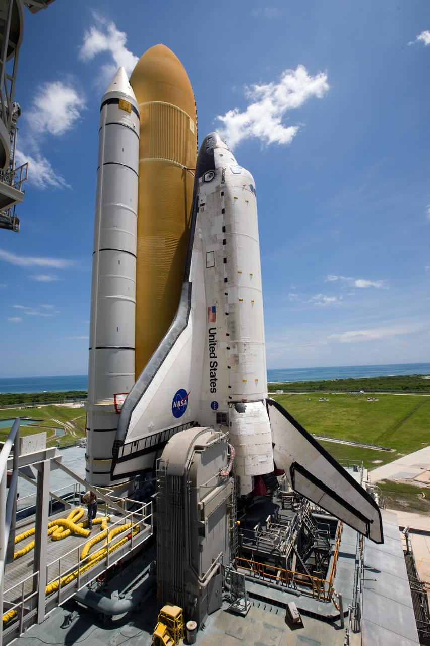
KENNEDY SPACE CENTER, FLA. -- On Launch Pad 39A at NASA's Kennedy Space Center, rollback of the rotating service structure (at left) reveals space shuttle Endeavour atop the mobile launcher platform. First motion was at 8:23 a.m. and rollback was complete at 8:55 a.m. Above the orange external tank is seen the "beanie cap" at the end of the gaseous oxygen vent arm, extending from the fixed service structure. Vapors are created as the liquid oxygen in the external tank boil off. The hood vents the gaseous oxygen vapors away from the space shuttle vehicle. Below is the orbiter access arm with the White Room at the end, flush against the shuttle. The crew gains access into the orbiter through the White Room. On either side of the main engines and below the wings are the tail service masts, which provide several umbilical connections to the orbiter, including a liquid-oxygen line through one and a liquid-hydrogen line through another. The rotating structure provides protected access to the orbiter for changeout and servicing of payloads at the pad. The structure is supported by a rotating bridge that pivots about a vertical axis on the west side of the pad's flame trench. After the RSS is rolled back, the orbiter is ready for fuel cell activation and external tank cryogenic propellant loading operations. The pad is cleared to the perimeter gate for operations to fill the external tank with about 500,000 gallons of cryogenic propellants used by the shuttle’s main engines. This is done at the pad approximately eight hours before the scheduled launch. Endeavour and its crew will deliver the first section of the Japan Aerospace Exploration Agency's Kibo laboratory and the Canadian Space Agency's two-armed robotic system, Dextre. Launch is scheduled for 2:28 a.m. EDT March 11. Photo credit: NASA/Kim Shiflett
KENNEDY SPACE CENTER, FLA. -- On Launch Pad 39A at NASA's Kennedy Space Center, rollback of the rotating service structure reveals space shuttle Endeavour atop the mobile launcher platform. First motion was at 8:23 a.m. and rollback was complete at 8:55 a.m. Above the orange external tank is seen the "beanie cap" at the end of the gaseous oxygen vent arm, extending from the fixed service structure. Vapors are created as the liquid oxygen in the external tank boil off. The hood vents the gaseous oxygen vapors away from the space shuttle vehicle. Below is the orbiter access arm with the White Room at the end, flush against the shuttle. The crew gains access into the orbiter through the White Room. On either side of the main engines and below the wings are the tail service masts, which provide several umbilical connections to the orbiter, including a liquid-oxygen line through one and a liquid-hydrogen line through another. The rotating structure provides protected access to the orbiter for changeout and servicing of payloads at the pad. The structure is supported by a rotating bridge that pivots about a vertical axis on the west side of the pad's flame trench. After the RSS is rolled back, the orbiter is ready for fuel cell activation and external tank cryogenic propellant loading operations. The pad is cleared to the perimeter gate for operations to fill the external tank with about 500,000 gallons of cryogenic propellants used by the shuttle’s main engines. This is done at the pad approximately eight hours before the scheduled launch. Endeavour and its crew will deliver the first section of the Japan Aerospace Exploration Agency's Kibo laboratory and the Canadian Space Agency's two-armed robotic system, Dextre. Launch is scheduled for 2:28 a.m. EDT March 11. Photo credit: NASA/Kim Shiflett
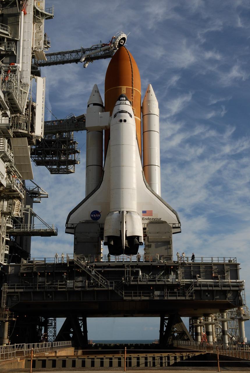
KENNEDY SPACE CENTER, FLA. -- On Launch Pad 39A at NASA's Kennedy Space Center, the rotating service structure has rolled away to uncover space shuttle Endeavour, resting on the mobile launcher platform. First motion was at 8:23 a.m. and rollback was complete at 8:55 a.m. Above the orange external tank is seen the "beanie cap" at the end of the gaseous oxygen vent arm, extending from the fixed service structure. Vapors are created as the liquid oxygen in the external tank boil off. The hood vents the gaseous oxygen vapors away from the space shuttle vehicle. Below is the orbiter access arm with the White Room at the end, flush against the shuttle. The crew gains access into the orbiter through the White Room. On either side of the main engines and below the wings are the tail service masts, which provide several umbilical connections to the orbiter, including a liquid-oxygen line through one and a liquid-hydrogen line through another. The rotating structure provides protected access to the orbiter for changeout and servicing of payloads at the pad. The structure is supported by a rotating bridge that pivots about a vertical axis on the west side of the pad's flame trench. After the RSS is rolled back, the orbiter is ready for fuel cell activation and external tank cryogenic propellant loading operations. The pad is cleared to the perimeter gate for operations to fill the external tank with about 500,000 gallons of cryogenic propellants used by the shuttle’s main engines. This is done at the pad approximately eight hours before the scheduled launch. Endeavour and its crew will deliver the first section of the Japan Aerospace Exploration Agency's Kibo laboratory and the Canadian Space Agency's two-armed robotic system, Dextre. Launch is scheduled for 2:28 a.m. EDT March 11. Photo credit: NASA/Kim Shiflett

KENNEDY SPACE CENTER, FLA. -- On Launch Pad 39A at NASA's Kennedy Space Center, the rotating service structure has rolled away to uncover space shuttle Endeavour. First motion was at 8:23 a.m. and rollback was complete at 8:55 a.m. Above the orange external tank is seen the "beanie cap" at the end of the gaseous oxygen vent arm, extending from the fixed service structure. Vapors are created as the liquid oxygen in the external tank boil off. The hood vents the gaseous oxygen vapors away from the space shuttle vehicle. The rotating structure provides protected access to the orbiter for changeout and servicing of payloads at the pad. The structure is supported by a rotating bridge that pivots about a vertical axis on the west side of the pad's flame trench. After the RSS is rolled back, the orbiter is ready for fuel cell activation and external tank cryogenic propellant loading operations. The pad is cleared to the perimeter gate for operations to fill the external tank with about 500,000 gallons of cryogenic propellants used by the shuttle’s main engines. This is done at the pad approximately eight hours before the scheduled launch. Endeavour and its crew will deliver the first section of the Japan Aerospace Exploration Agency's Kibo laboratory and the Canadian Space Agency's two-armed robotic system, Dextre. Launch is scheduled for 2:28 a.m. EDT March 11. Photo credit: NASA/Kim Shiflett
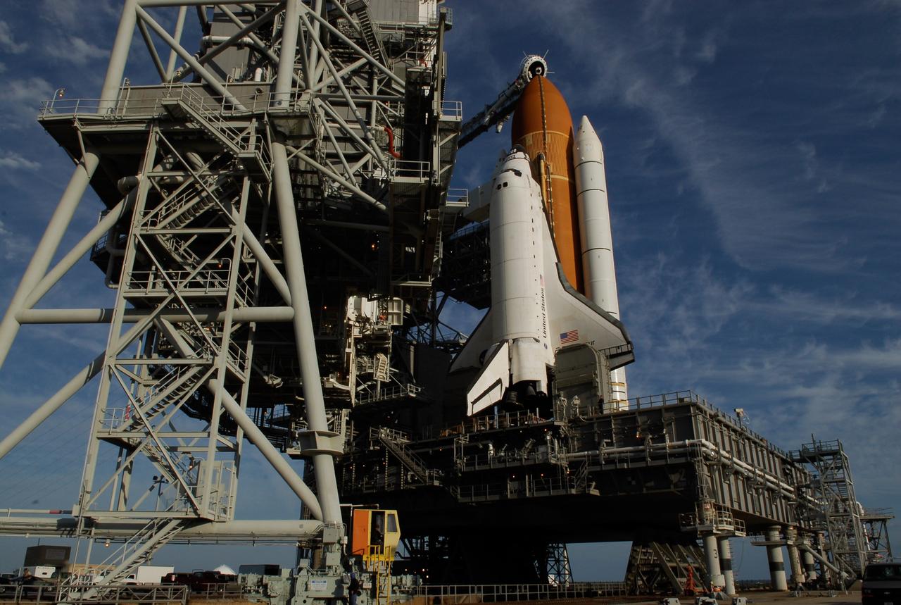
KENNEDY SPACE CENTER, FLA. -- On Launch Pad 39A at NASA's Kennedy Space Center, the rotating service structure is rolling on its axis to uncover space shuttle Endeavour. First motion was at 8:23 a.m. and rollback was complete at 8:55 a.m. Above the orange external tank is seen the "beanie cap" at the end of the gaseous oxygen vent arm, extending from the fixed service structure. Vapors are created as the liquid oxygen in the external tank boil off. The hood vents the gaseous oxygen vapors away from the space shuttle vehicle. The rotating structure provides protected access to the orbiter for changeout and servicing of payloads at the pad. The structure is supported by a rotating bridge that pivots about a vertical axis on the west side of the pad's flame trench. After the RSS is rolled back, the orbiter is ready for fuel cell activation and external tank cryogenic propellant loading operations. The pad is cleared to the perimeter gate for operations to fill the external tank with about 500,000 gallons of cryogenic propellants used by the shuttle’s main engines. This is done at the pad approximately eight hours before the scheduled launch. Endeavour and its crew will deliver the first section of the Japan Aerospace Exploration Agency's Kibo laboratory and the Canadian Space Agency's two-armed robotic system, Dextre. Launch is scheduled for 2:28 a.m. EDT March 11. Photo credit: NASA/Kim Shiflett
KENNEDY SPACE CENTER, FLA. -- Space Shuttle Endeavour is on Launch Pad 39A and ready for prelaunch processing after a nearly 7-hour trip from the Vehicle Assembly Building. First motion out of the VAB was at 8:10 p.m. July 10, and the shuttle was hard down on the pad at 3:02 a.m. July 11. The orbiter access arm is already extended to the orbiter from the fixed service structure at left. On top of the structure is the 80-foot-tall lightning mast that helps provide protection from lightning on the pad. The shuttle sits on a mobile launcher platform. Part of the platform and seen below the orbiter's wings are the tail masts, which provide several umbilical connections to the orbiter, including a liquid-oxygen line through one and a liquid-hydrogen line through another. Endeavour is scheduled to launch on mission STS-118 on Aug. 7. During the mission, Endeavour will carry into orbit the S5 truss, SPACEHAB module and external stowage platform 3. The mission is the 22nd flight to the International Space Station and will mark the first flight of Mission Specialist Barbara Morgan, the teacher-turned-astronaut whose association with NASA began more than 20 years ago. STS-118 will be the first flight since 2002 for Endeavour, which has undergone extensive modifications, including the addition of safety upgrades already added to orbiters Discovery and Atlantis. Photo credit: NASA/George Shelton
CAPE CANAVERAL, Fla. -- Bathed in lights surrounding Launch Pad 39A and its structures at NASA's Kennedy Space Center, space shuttle Discovery is poised for launch on the STS-124 mission after rollback of the rotating service structure. First motion was at 8:33 p.m. and rollback was complete at 9:07 p.m. The structure provides protected access to the shuttle for changeout and servicing of payloads at the pad. It is supported by a rotating bridge that pivots on a vertical axis on the west side of the pad's flame trench. After the RSS is rolled back, the orbiter is ready for fuel cell activation and external tank cryogenic propellant loading operations. The pad is cleared to the perimeter gate for operations to fill the external tank with about 500,000 gallons of cryogenic propellants used by the shuttle’s main engines. This is done at the pad approximately eight hours before the scheduled launch. Behind the shuttle is the orange external tank and the two solid rocket boosters (only one seen here). Beneath the shuttle's starboard wing is one of two tail service masts, which provide several umbilical connections to the orbiter, including a liquid-oxygen line through one and a liquid-hydrogen line through another. The STS-124 mission is the second of three flights launching components to complete the Japan Aerospace Exploration Agency's Kibo laboratory. The shuttle crew will install Kibo's large Japanese Pressurized Module and its remote manipulator system, or RMS. The 14-day flight includes three spacewalks. Launch is scheduled for 5:02 p.m. May 31. Photo credit: NASA/Troy Cryder
CAPE CANAVERAL, Fla. – After rollback of the rotating service structure, or RSS, on Launch Pad 39A at NASA's Kennedy Space Center in Florida, space shuttle Endeavour is closer to launch. Above the external tank is the "beanie cap," the oxygen vent hood that is designed to vent gaseous oxygen vapors away from the shuttle. At center against Endeavour's cockpit is seen the White Room at the end of the orbiter access arm. The White Room provides the astronauts entry into the shuttle. Endeavour sits on the mobile launcher platform, which straddles the flame trench below. On either side of the engine nozzles are the tail masts, which provide several umbilical connections to the orbiter, including a liquid-oxygen line through one and a liquid-hydrogen line through another. First motion of the RSS was at 10:15 a.m. EDT. The rollback is in preparation for Endeavour's liftoff on the STS-127 mission with a crew of seven. This is the second launch attempt for Endeavour after the June 13 launch was scrubbed due to a hydrogen leak at the Ground Umbilical Carrier Plate during tanking June 12. The launch will be Endeavour's 23rd flight. The shuttle will carry the Japanese Experiment Module's Exposed Facility, or JEM-EF, and the Experiment Logistics Module-Exposed Section, or ELM-ES, on STS-127. The mission is the final of three flights dedicated to the assembly of the Japan Aerospace Exploration Agency's Kibo laboratory complex on the space station. Endeavour's launch is scheduled for June 17 at 5:40 a.m. EDT. Photo credit: NASA/Kim Shiflett
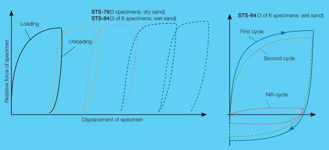
On STS-89, three Mechanics of Granular Materials (MGM) test cells were subjected to five cycles of compression and relief (left) and three were subjected to shorter displacement cycles that simulate motion during an earthquake (right). In the compression/relief tests, the sand particles rearranged themselves and slightly re-expanded the column during relief. In the short displacement tests, the specimen's resistance to compression decreases, even though the displacement remains the same. The specimens were cycled up to 100 times or until the resistive force was less than 1% that of the previous cycle. Sand and soil grains have faces that can cause friction as they roll and slide against each other, or even cause sticking and form small voids between grains. This complex behavior can cause soil to behave like a liquid under certain conditions such as earthquakes or when powders are handled in industrial processes. Mechanics of Granular Materials (MGM) experiments aboard the Space Shuttle use the microgravity of space to simulate this behavior under conditons that carnot be achieved in laboratory tests on Earth. MGM is shedding light on the behavior of fine-grain materials under low effective stresses. Applications include earthquake engineering, granular flow technologies (such as powder feed systems for pharmaceuticals and fertilizers), and terrestrial and planetary geology. Nine MGM specimens have flown on two Space Shuttle flights. Another three are scheduled to fly on STS-107. The principal investigator is Stein Sture of the University of Colorado at Boulder. Credit: NASA/Marshall Space Flight Center (MSFC)
CAPE CANAVERAL, Fla. -- Against the dark sky, lights bathe space shuttle Discovery, revealed after rollback of the rotating service structure in preparation for launch on the STS-124 mission. First motion was at 8:33 p.m. and rollback was complete at 9:07 p.m. The rotating structure provides protected access to the shuttle for changeout and servicing of payloads at the pad. It is supported by a rotating bridge that pivots on a vertical axis on the west side of the pad's flame trench. After the RSS is rolled back, the orbiter is ready for fuel cell activation and external tank cryogenic propellant loading operations. The pad is cleared to the perimeter gate for operations to fill the external tank with about 500,000 gallons of cryogenic propellants used by the shuttle’s main engines. This is done at the pad approximately eight hours before the scheduled launch. Above the orange external tank is the oxygen vent hood, called the "beanie cap," at the end of the gaseous oxygen vent arm extending from the fixed service structure. Vapors are created as the liquid oxygen in the external tank boil off. The hood vents the gaseous oxygen vapors away from the space shuttle vehicle. Below is the orbiter access arm with the White Room at the end, flush against the shuttle. The White Room provides access into the shuttle. The STS-124 mission is the second of three flights launching components to complete the Japan Aerospace Exploration Agency's Kibo laboratory. The shuttle crew will install Kibo's large Japanese Pressurized Module and its remote manipulator system, or RMS. The 14-day flight includes three spacewalks. Launch is scheduled for 5:02 p.m. May 31. Photo credit: NASA/Troy Cryder
CAPE CANAVERAL, Fla. -- On Launch Pad 39A at NASA's Kennedy Space Center, the rotating service structure, or RSS, has rolled back on its axis to uncover space shuttle Discovery, lighted against the night sky, in preparation for launch on the STS-124 mission. Support for the outer end of the bridge is provided by two eight-wheel, motor-driven trucks (one is seen at bottom left) that move along circular twin rails installed flush with the pad surface. First motion was at 8:33 p.m. and rollback was complete at 9:07 p.m. The structure provides protected access to the shuttle for changeout and servicing of payloads at the pad. It is supported by a rotating bridge that pivots on a vertical axis on the west side of the pad's flame trench. After the RSS is rolled back, the orbiter is ready for fuel cell activation and external tank cryogenic propellant loading operations. The pad is cleared to the perimeter gate for operations to fill the external tank with about 500,000 gallons of cryogenic propellants used by the shuttle’s main engines. This is done at the pad approximately eight hours before the scheduled launch. Above the orange external tank is the oxygen vent hood, called the "beanie cap," at the end of the gaseous oxygen vent arm extending from the fixed service structure. Vapors are created as the liquid oxygen in the external tank boil off. The hood vents the gaseous oxygen vapors away from the space shuttle vehicle. Below is the orbiter access arm with the White Room at the end, flush against the shuttle. The White Room provides access into the shuttle. The STS-124 mission is the second of three flights launching components to complete the Japan Aerospace Exploration Agency's Kibo laboratory. The shuttle crew will install Kibo's large Japanese Pressurized Module and its remote manipulator system, or RMS. The 14-day flight includes three spacewalks. Launch is scheduled for 5:02 p.m. May 31. Photo credit: NASA/Troy Cryder
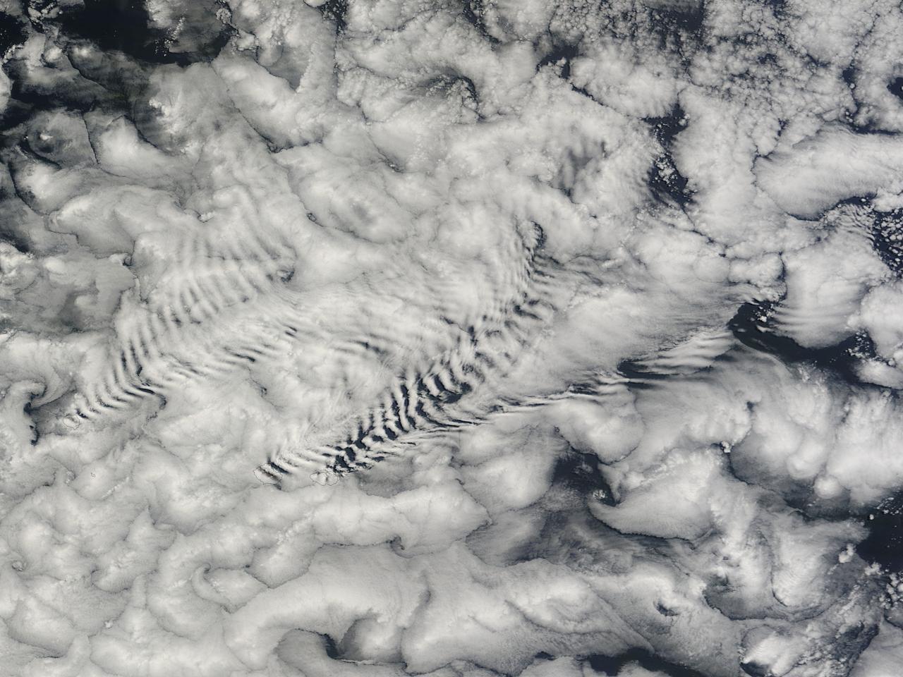
There are special places on Earth that sometimes write their personal signature in the clouds. The Crozet Islands are one such place, thanks to the tall volcanic peaks that grace the islands. When air flows around these tall peaks, it gets pushed around the islands as well as up and over the peak. The net effect of the flowing air flowing around the solid, tall peaks is much like the solid bow of a ship cutting through standing water. In each case v-shaped waves are formed behind the motion. In liquid, this is called a wake; in the atmosphere, when clouds are present or created, they are known as ship-wave-shaped clouds. The Moderate Resolution Imaging Spectroradiometer (MODIS) aboard NASA’s Terra satellite captured this true-color image as it passed over the Crozet Islands on November 26, 2014. Three distinct waves are seen behind the three largest islands. From west to east these are Pig Island, Possession Island and East Island. Credit: NASA/GSFC/Jeff Schmaltz/MODIS Land Rapid Response Team <b><a href="http://www.nasa.gov/audience/formedia/features/MP_Photo_Guidelines.html" rel="nofollow">NASA image use policy.</a></b> <b><a href="http://www.nasa.gov/centers/goddard/home/index.html" rel="nofollow">NASA Goddard Space Flight Center</a></b> enables NASA’s mission through four scientific endeavors: Earth Science, Heliophysics, Solar System Exploration, and Astrophysics. Goddard plays a leading role in NASA’s accomplishments by contributing compelling scientific knowledge to advance the Agency’s mission. <b>Follow us on <a href="http://twitter.com/NASAGoddardPix" rel="nofollow">Twitter</a></b> <b>Like us on <a href="http://www.facebook.com/pages/Greenbelt-MD/NASA-Goddard/395013845897?ref=tsd" rel="nofollow">Facebook</a></b> <b>Find us on <a href="http://instagram.com/nasagoddard?vm=grid" rel="nofollow">Instagram</a></b>

ISS016-E-027426 (5 Feb. 2008) --- Cumulonimbus Cloud over Africa is featured in this image photographed by an Expedition 16 crewmember on the International Space Station. Deemed by many meteorologists as one of the most impressive of cloud formations, cumulonimbus (from the Latin for "puffy" and "dark") clouds form due to vigorous convection of warm and moist unstable air. Surface air warmed by the Sun-heated ground surface rises, and if sufficient atmospheric moisture is present, water droplets will condense as the air mass encounters cooler air at higher altitudes. The air mass itself also expands and cools as it rises due to decreasing atmospheric pressure, a process known as adiabatic cooling. This type of convection is common in tropical latitudes year-round and during the summer season at higher latitudes. As water in the rising air mass condenses and changes from a gaseous to a liquid state, it releases energy to its surroundings, further heating the surrounding air and leading to more convection and rising of the cloud mass to higher altitudes. This leads to the characteristic vertical "towers" associated with cumulonimbus clouds, an excellent example of which is visible in this image (right). If enough moisture is present to condense and continue heating the cloud mass through several convective cycles, a tower can rise to altitudes of approximately 10 kilometers at high latitudes to 20 kilometers in the tropics -- before encountering a region of the atmosphere known as the tropopause. The tropopause is characterized by a strong temperature inversion where the atmosphere is dryer and no longer cools with altitude. This halts further vertical motion of the cloud mass, and causes flattening and spreading of the cloud tops into an anvil-shaped cloud as illustrated by this oblique photograph. The view direction is at an angle from the vertical, rather than straight "down" towards the Earth's surface. The image, photographed while the International Space Station was passing over western Africa near the Senegal-Mali border, shows a fully-formed anvil cloud with numerous smaller cumulonimbus towers rising near it. The high energetics of these storm systems typically make them hazardous due to associated heavy precipitation, lightning, high wind speeds and possible tornadoes.
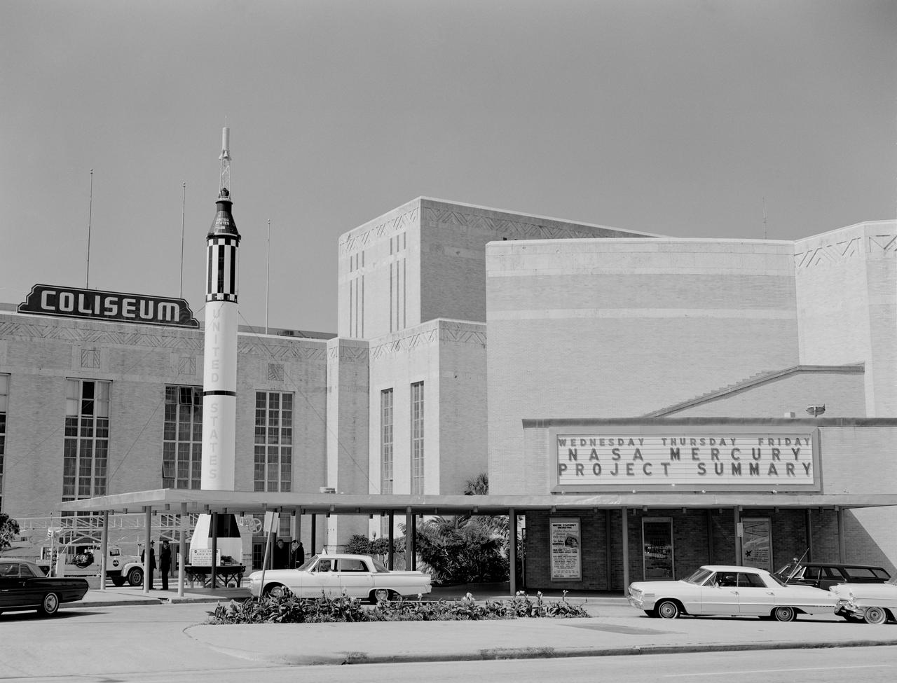
In October 1963, the Project Mercury Summary Conference was held in the Houston, TX, Coliseum. This series of 44 photos is documentation of that conference. A view of the Houston, TX, Coliseum, and parking area in front with a Mercury Redstone Rocket setup in the parking lot for display (S63-16451). A view of an Air Force Atlas Rocket, a Mercury Redstone Rocket, and a Mercury Spacecraft on a test booster on display in the front area of the Coliseum (S63-16452). A view an Air Force Atlas Rocket and a Mercury Redstone Rocket set up for display with the Houston City Hall in the background (S63- 16453). This view shows the Atlas Rocket, Mercury Redstone, and Mercury Test Rocket with the Houston, TX, Coliseum in the background (S63- 16454). A balcony view, from the audience right side, of the attendees looking at the stage (S63-16455). A view of the NASA Space Science Demonstration with equipment setup on a table, center stage and Space Science Specialist briefing the group as he pours Liquid Oxygen into a beaker (S63-16456). View of the audience from the balcony on the audience right showing the speakers lecturn on stage to the audience left (S63-16457). A view of attendees in the lobby. Bennet James, MSC Public Affairs Office is seen to the left of center (S63-16458). Another view of the attendees in the lobby (S63- 16459). In this view, Astronaut Neil Armstrong is seen writing as others look on (S63-16460). In this view of the attendees, Astronauts Buzz Aldrin and Walt Cunningham are seen in the center of the shot. The October Calendar of Events is visable in the background (S63-16461). Dr. Charles Berry is seen in this view to the right of center, seated in the audience (S63-16462). View of " Special Registration " and the five ladies working there (S63-16463). A view from behind the special registration table, of the attendees being registered (S63-16464). A view of a conference table with a panel seated. (R-L): Dr. Robert R. Gilruth, Hugh L. Dryden, Walter C. Williams, and an unidentified man (S63- 16465). A closeup of the panel at the table with Dr. Gilruth on the left (S63-16466). About the same shot as number S63-16462, Dr. Berry is seen in this shot as well (S63-16467). In this view the audio setup is seen. In the audience, (L-R): C. C. Kraft, Vernon E. (Buddy) Powell, Public Affairs Office (PAO); and, in the foreground mixing the audio is Art Tantillo; and, at the recorder is Doyle Hodges both of the audio people are contractors that work for PAO at MSC (S63-16468). In this view Maxime Faget is seen speaking at the lecturn (S63-16469). Unidentified person at the lecturn (S63-16470). In this view the motion picture cameras and personel are shown documenting the conference (S63-16471). A motion picture cameraman in the balcony is shown filming the audience during a break (S63- 16472). Family members enjoy an exhibit (S63-16473). A young person gets a boost to look in a Gemini Capsule on display (S63-16474). A young person looks at the Gemini Capsule on display (S63-16475). Dr. Robert R. Gilruth is seen at the conference table (S63-16476). Walt Williams is seen in this view at the conference table (S63-16477). Unidentified man sitting next to Walt Williams (S63-16478). (L-R): Seated at the conference table, Dr. Robert Gilruth, Hugh L. Dryden, and Walt Williams (S63- 16479). Group in lobby faces visable, (L-R): Walt Williams, unidentified person, Dr. Robert Gilruth, Congressman (S63-16480). Man in uniform at the lecturn (S63-16481). Astronaut Leroy Gordon Cooper at the lecturn (S63-16482). Astronaut Cooper at the lecturn with a picture on the screen with the title, " Astronaut Names for Spacecraft " (S63-16483). Dr. Gilruth at the lecturn (S63-16484). Walt Williams at the lecturn (S63-16485). Unidentified man at the lecturn (S63-16486). John H. Boynton addresses the Summary Conference (S63-16487). (L-R): Astronaut Leroy Gordon Cooper, Mrs. Cooper, Senator Cris Cole, and Mrs. Cole (S63- 16488). In this view in the lobby, Senator and Mrs. Cris Cole, with Astronaut Gordon Cooper standing near the heatshield, and Mrs. Cooper; next, on the right is a press photographer (S63-16489). (L-R): Astronaut L. Gordon Cooper and Mrs. Cooper, unidentified man, and Senator Walter Richter (S63-16490). (L-R): Eugene Horton, partially obscured, briefs a group on the Mercury Spacecraft, an unidentified person, Harold Ogden, a female senator, Senator Chris Cole, Mrs. Cole, an unidentified female, Senator Walter Richter, Jim Bower, and an unidentified female (S63-16491). In this view, Mrs. Jim Bates is seen in the center, and Senator Walter Richter to the right (S63- 16492). The next three (3) shots are 4X5 CN (S63-16493 - S63-16495). In this view a NASA Space Science Demonstration is seen (S63-16493). In this view a shot of the conference table is seen, and, (L-R): Dr. Robert R. Gilruth, Hugh L. Dryden, Mr. Walter Williams, and an unidentfied man (S63-16494 - S63-16495). HOUSTON, TX

The veils of Saturn's most mysterious moon have begun to lift in Cassini's eagerly awaited first glimpse of the surface of Titan, a world where scientists believe organic matter rains from hazy skies and seas of liquid hydrocarbons dot a frigid surface. Surface features previously observed only from Earth-based telescopes are now visible in images of Titan taken in mid-April by Cassini through one of the narrow angle camera's spectral filters specifically designed to penetrate the thick atmosphere. The image scale is 230 kilometers (143 miles) per pixel, and it rivals the best Earth-based images. The two images displayed here show Titan from a vantage point 17 degrees below its equator, yielding a view from 50 degrees north latitude all the way to its south pole. The image on the left was taken four days after the image on the right. Titan rotated 90 degrees in that time. The two images combined cover a region extending halfway around the moon. The observed brightness variations suggest a diverse surface, with variations in average reflectivity on scales of a couple hundred kilometers. The images were taken through a narrow filter centered at 938 nanometers, a spectral region in which the only obstacle to light is the carbon-based, organic haze. Despite the rather long 38-second exposure times, there is no noticeable smear due to spacecraft motion. The images have been magnified 10 times and enhanced in contrast to bring out details. No further processing to remove the effects of the overlying atmosphere has been performed. The superimposed grid over the images illustrates the orientation of Titan -- north is up and rotated 25 degrees to the left -- as well as the geographical regions of the satellite that are illuminated and visible. The yellow curve marks the position of the boundary between day and night on Titan. The enhanced image contrast makes the region within 20 degrees of this day and night division darker than usual. The Sun illuminates Titan from the right at a phase angle of 66 degrees. Because the Sun is in the southern hemisphere as seen from Titan, the north pole is canted relative to the boundary between day and night by 25 degrees. Also shown here is a map of relative surface brightness variations on Titan as measured in images taken in the 1080-nanometer spectral region in 1997 and 1998 by the Near Infrared Camera and Multi-Object Spectrometer on NASA's Hubble Space Telescope. These images have scales of 300 kilometers (186 miles) per pixel. The map colors indicate different surface reflectivities. From darkest to brightest, the color progression is: deep blue (darkest), light blue, green, yellow, red and deep red (brightest). The large, continent-sized, red feature extending from 60 degrees to 150 degrees west longitude is called Xanadu. It is unclear whether Xanadu is a mountain range, giant basin, smooth plain, or a combination of all three. It may be dotted with hydrocarbon lakes but that is also unknown. All that is presently known is that in Earth-based images, it is the brightest region on Titan. A comparison between the Cassini images and the Hubble map indicates that Xanadu is visible as a bright region in the Cassini image on the right. The dark blue northwest-southeast trending feature from 210 degrees to 250 degrees west longitude, and the bright yellow/green region to the east (right) and southeast of it at minus 50 degrees latitude and 180 to 230 degrees west longitude on the Hubble map, can both be seen in the image on the left. It is noteworthy that the surface is visible to Cassini from its present approach viewing geometry, which is not the most favourable for surface viewing. These early Cassini observations are promising for upcoming imaging sequences of Titan in which the resolution improves by a factor of five over the next two months. These results are encouraging for future, in-orbit observations of Titan that will be acquired from lower, more favorable phase angles. The first opportunity to view small-scale features (2 kilometers or 1.2 miles) on the surface comes during a 350,000 kilometer (217,500 mile) flyby over Titan's south pole on July 2, 2004, only 30 hours after Cassini's insertion into orbit around the ringed planet. http://photojournal.jpl.nasa.gov/catalog/PIA05390