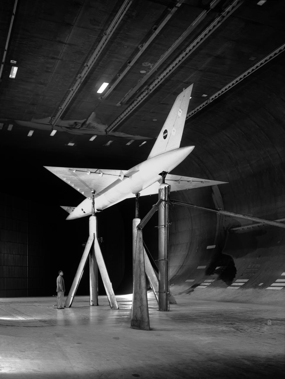
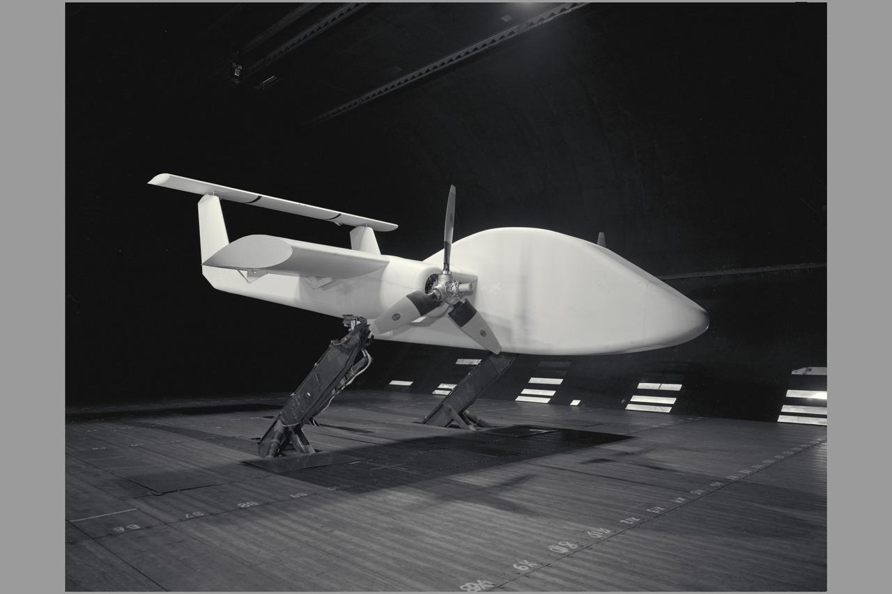
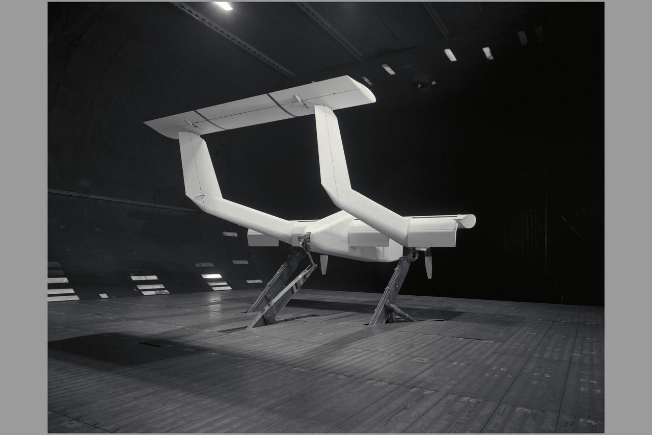
Low Speed investigation of a supersonic transport model with delta wing and delta conard, in the 40x80 Wind Tunnel. R 975 T Zero angel of attack. 3/4 rear view from below.
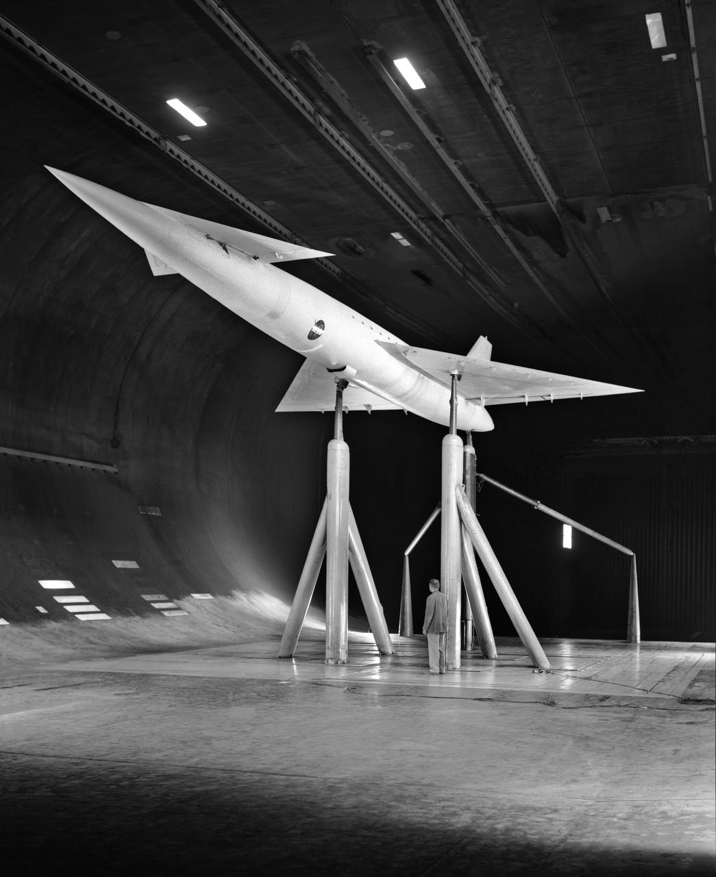
Low Speed investigation of a supersonic transport model in the 40x80 Wind Tunnel. 03/01/1961 R 975 T Zero angel of attack. Supersonic transport with delta wing and delta conard. 3/4 front view.
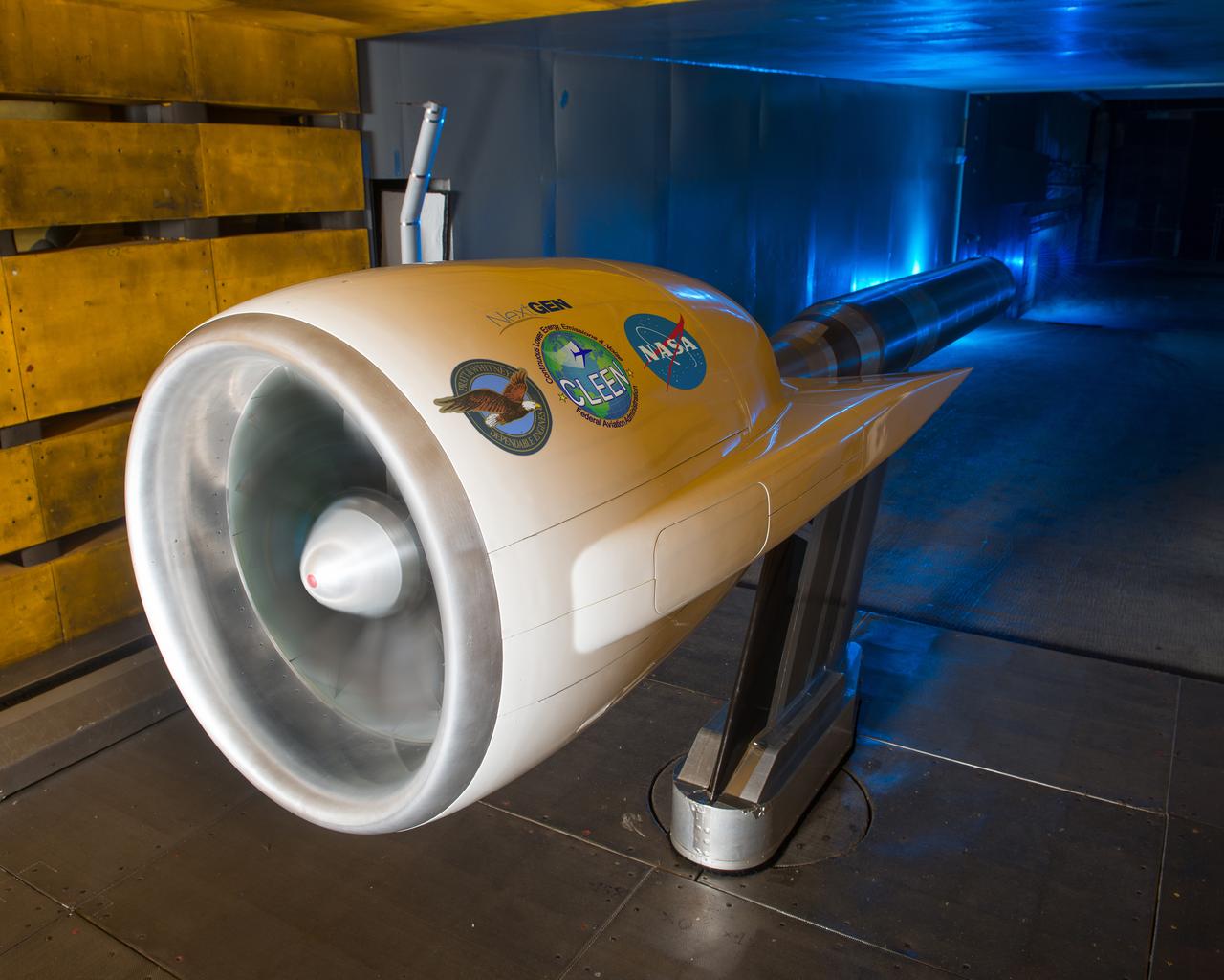
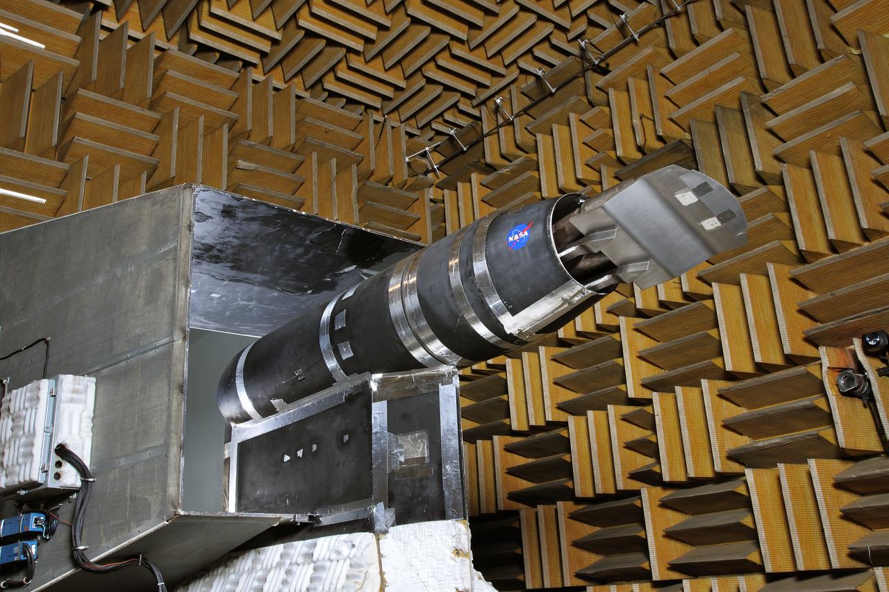
Ultra High Bypass Integrated System Test Testing of an Ultra High Bypass Ratio Turbofan model in the 9-by 15-Foot Low Speed Wind Tunnel. Pratt & Whitney designed the experimental engine to meet new efficiency and noise reduction targets for commercial aircraft set by NASA and the Federal Aviation Administration. The 9-by 15 tests analyzed two noise reduction technologies.
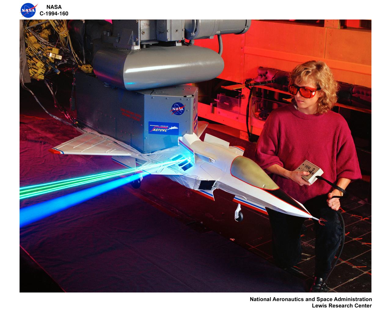
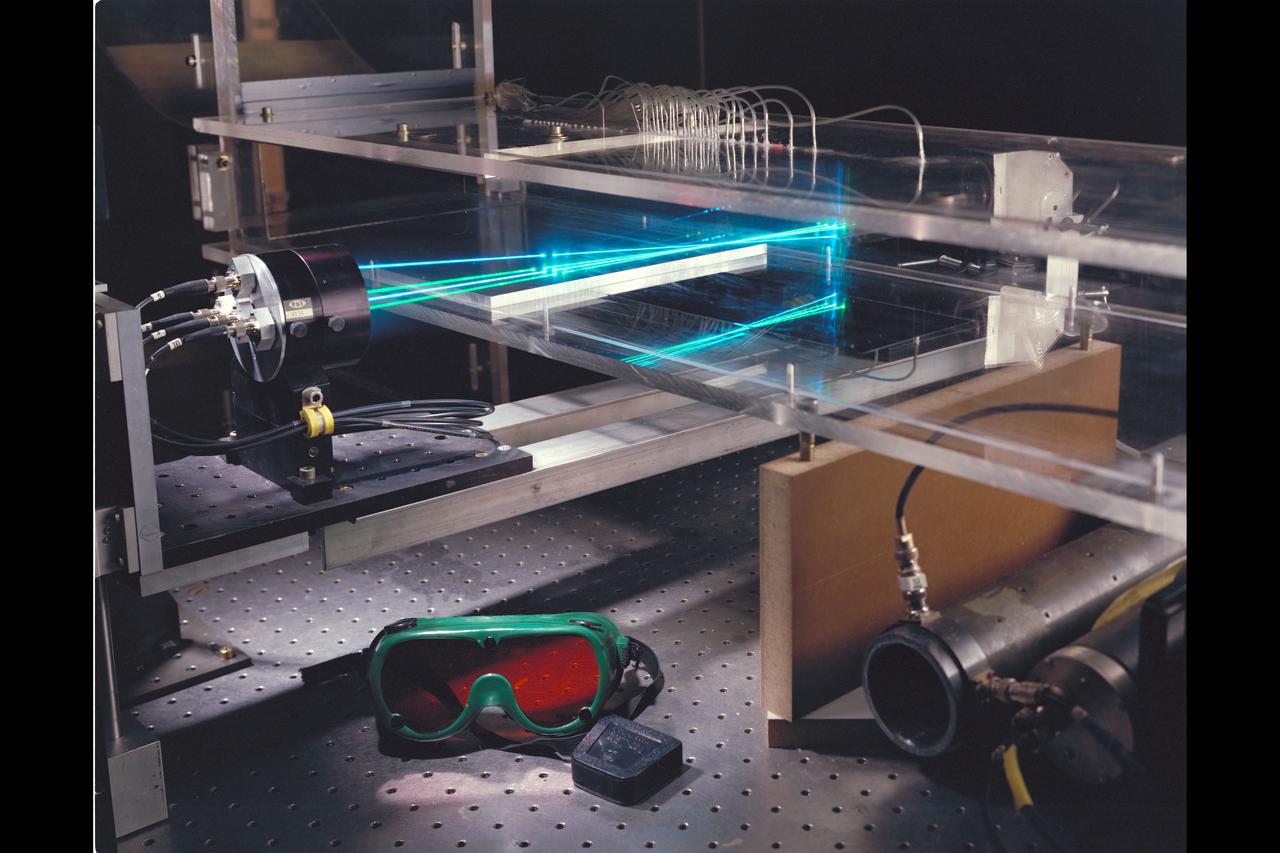
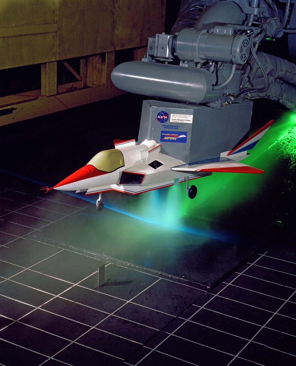
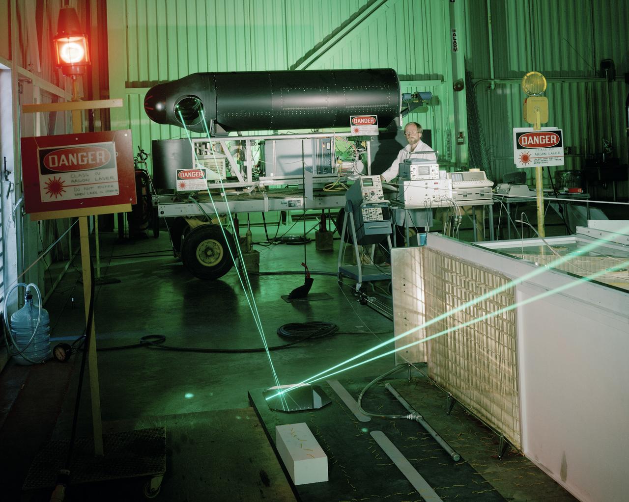
LASER Velocimetry System for Flow Measurement. Advanced Short Takeoff and Vertical Landing, ASTOVL model n the 9x15 foot Low Speed Wind Tunnel, LSWT
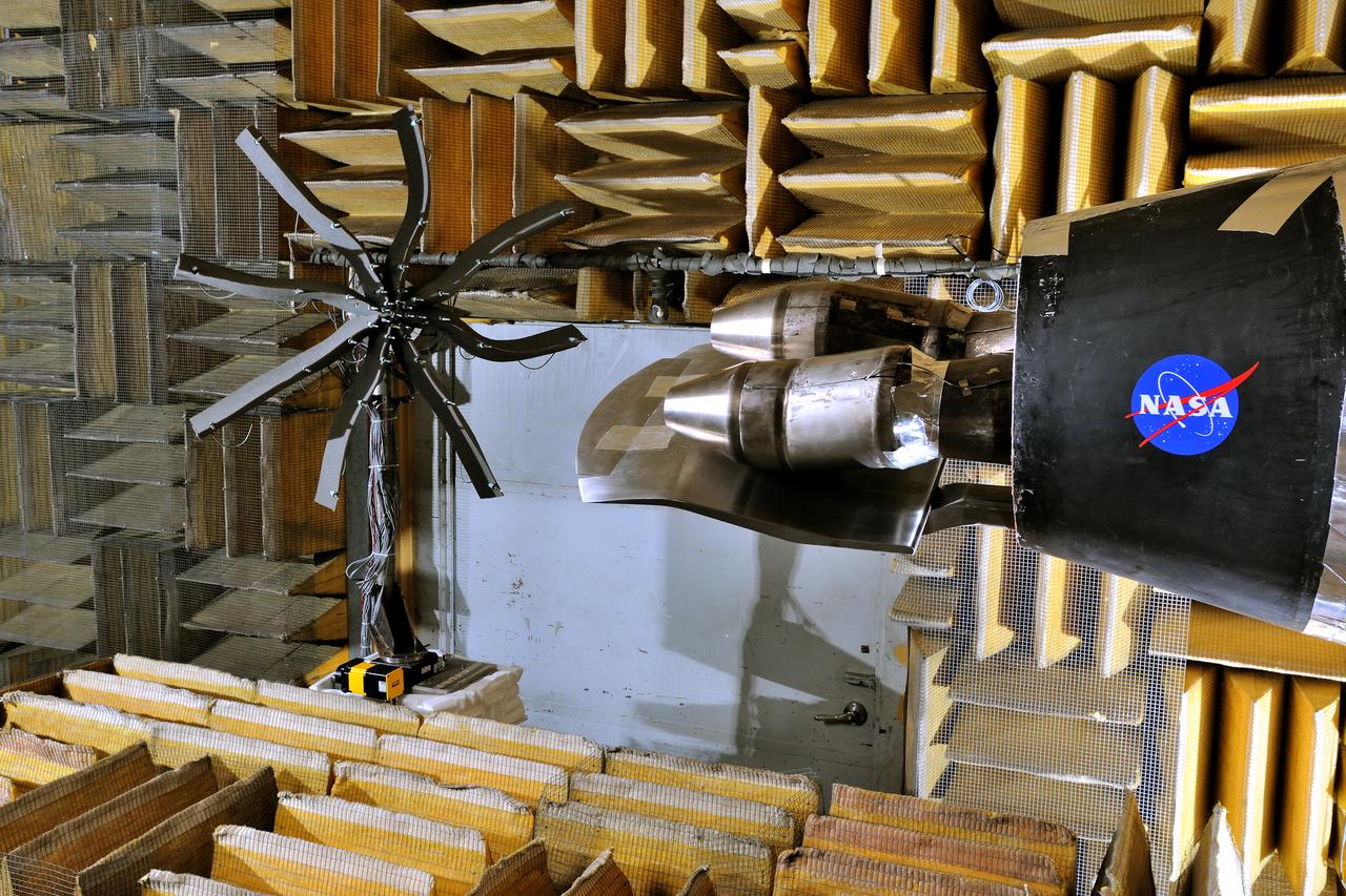
LSAWT\Twin Jet Test with HWB Model\JEDA Measurements Low Speed Aeroacoustic Wind Tunnel\Twin Jet Model System \Hybrid Wing Model Installed\ Measurement Technique: Jet Directional Array (JEDA)
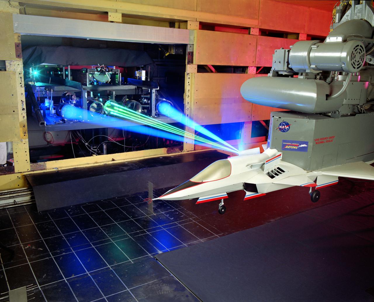
The 9x15 low speed tunnel tests take off and landing of aircraft. The laser velocimetry system for flow measurement show here, with the color blue and green lasers, measures engine exhaust that comes back up from the ground. The STOVL model n the 9x15 low speed wind tunnel, building 39, is similar to the British Harrier aircraft.
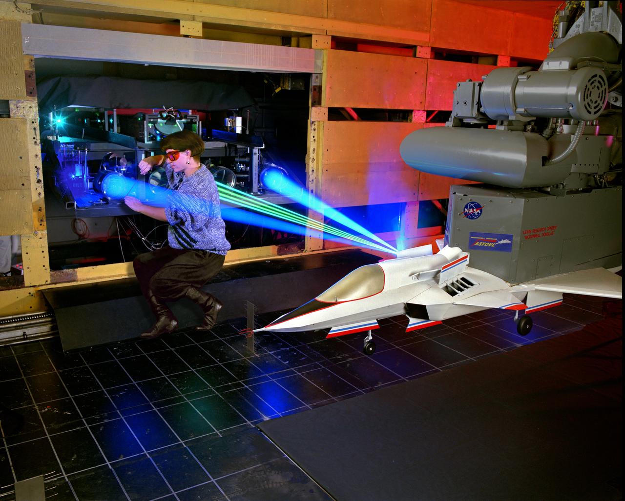
The 9x15 low speed tunnel tests take off and landing of aircraft. The laser velocimetry system for flow measurement show here, with the color blue and green lasers, measures engine exhaust that comes back up from the ground. The STOVL model n the 9x15 low speed wind tunnel, building 39, is similar to the British Harrier aircraft.
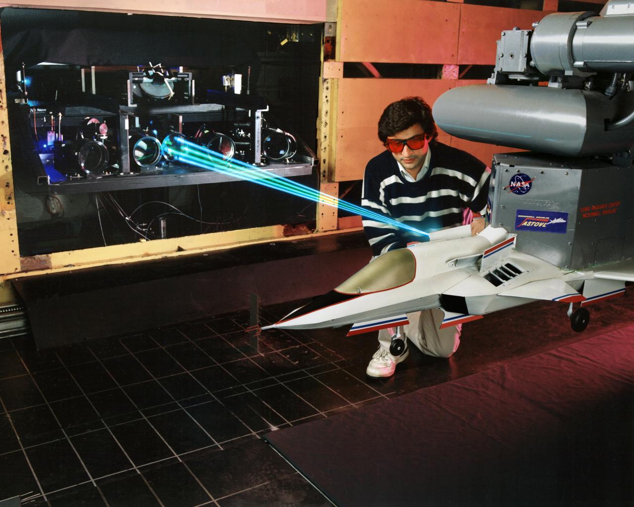
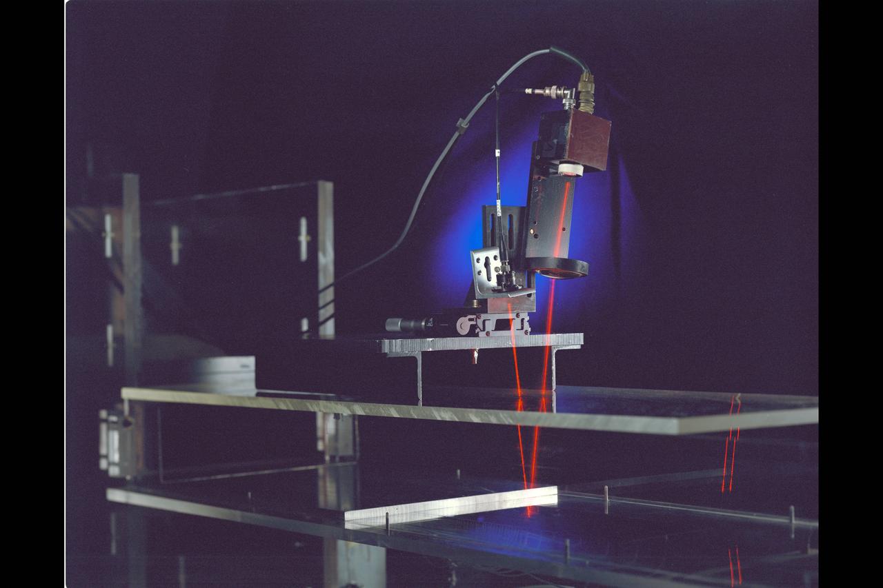
A spectrally resolved Rayleigh/Mie scattering diagnostic was developed to measure temperature and wing span wise velocity in the vicinity of an ASTOVL aircraft model tested in the Lewis, now Glenn, 9x15 Low Speed Wind Tunnel. Shown is a Fabry-Perot interferometer that uses only the blue light from a laser to measure static temperature and velocity near the lift nozzles and suction systems.
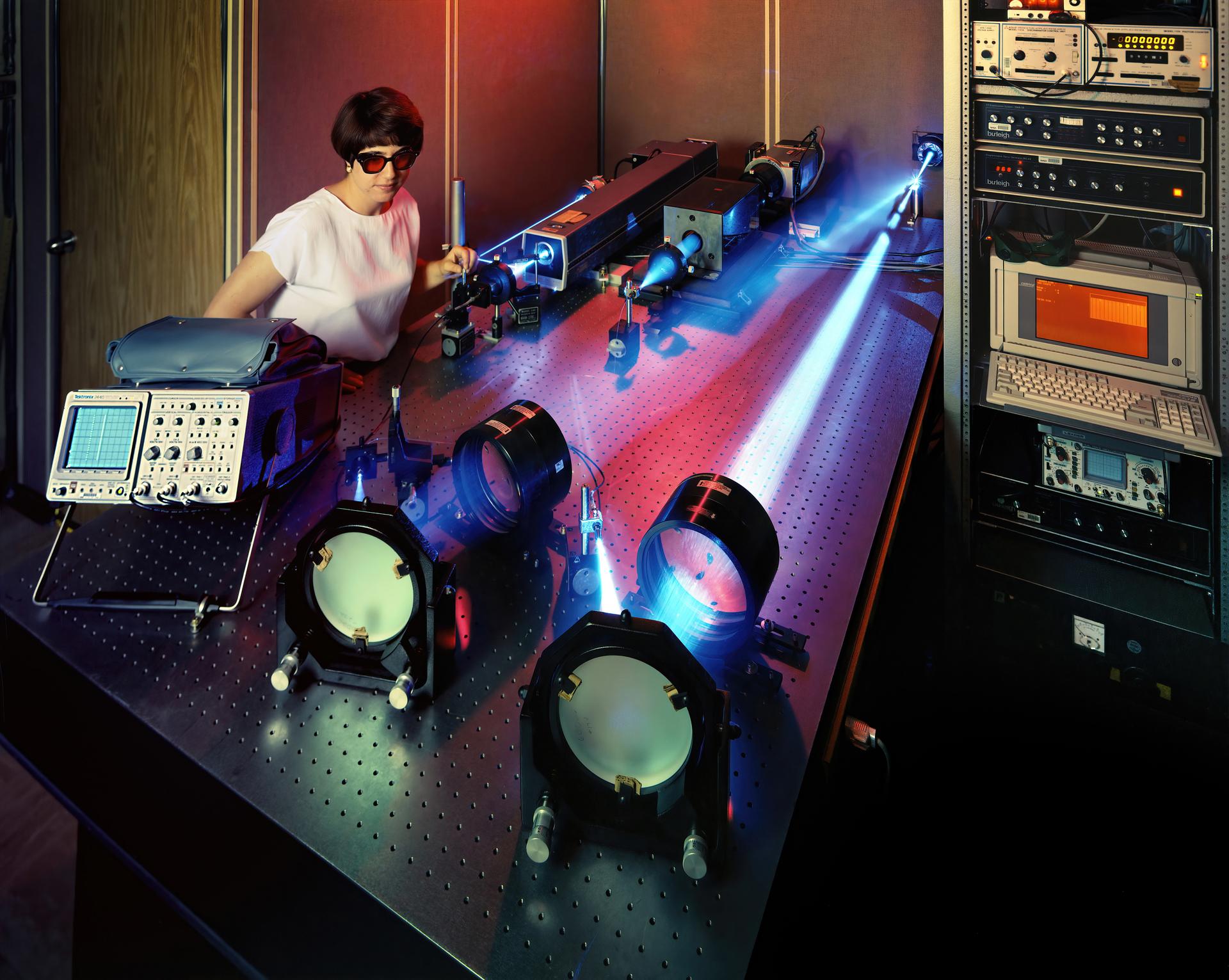
A spectrally resolved Rayleigh/Mie scattering diagnostic was developed to measure temperature and wingspan wise velocity in the vicinity of an ASTOVL aircraft model tested in the Lewis, now Glenn, 9x15 Low Speed Wind Tunnel. This was done for the Phase III hot gas ingestion study of ground-effect flow-field on such aircraft during hover or vertical landing.
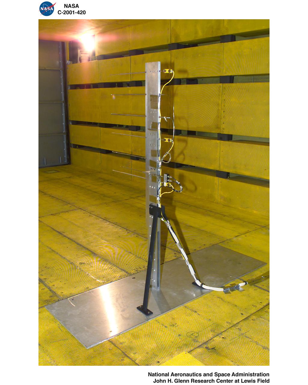
LOW SPEED WIND TUNNEL CALIBRATION HARDWARE IN 9X15 FOOT WIND TUNNEL TEST SECTION
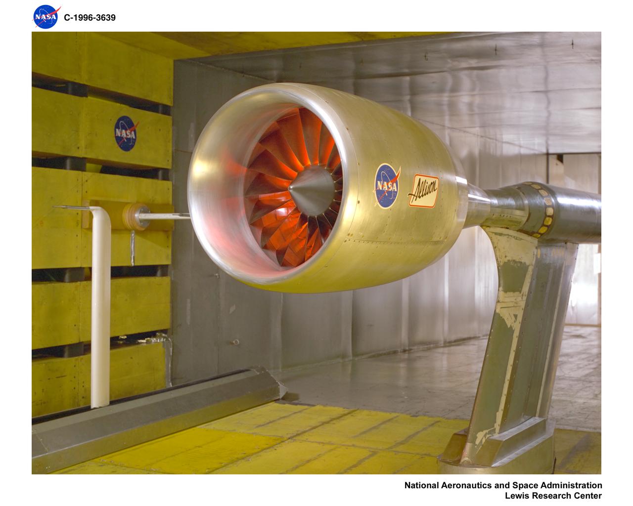
ALLISON LOW SPEED NOISE FAN WITH SWEPT / LEANED STATORS IN 9X15 FOOT LOW SPEED WIND TUNNEL
![Astronaut Neil Armstrong examines a Vertical and Short Takeoff and Landing test setup in the 9- by 15-Foot Low Speed Wind Tunnel at the National Aeronautics and Space Administration (NASA) Lewis Research Center. Armstrong spent February 6, 1970 at Lewis attending technical meetings and touring some facilities. Just six months after Armstrong had returned from the moon looming agency budget cuts were already a concern in his comments. He noted that NASA had to “find a balanced approach…and [make] aggressive use of available facilities.” Armstrong spent four months at the center as a research pilot in 1955. Armstrong had served as a Navy pilot during the Korean War then earned a degree in aeronautical engineering at Purdue University. He was recruited by Lewis while at Purdue and began at the center shortly after graduation. During his brief tenure in Cleveland Armstrong served as both a test pilot and research engineer, primarily involved with icing research. In his role as research pilot Armstrong also flew a North American F-82 Twin Mustang over the ocean near Wallops Island to launch small instrumented rockets from high altitudes down into the atmosphere to obtain high Mach numbers. After four months in Cleveland a position opened up at what is today the Dryden Flight Research Center. Armstrong’s career in Cleveland officially ended on June 30, 1955.](https://images-assets.nasa.gov/image/GRC-1970-C-00473/GRC-1970-C-00473~medium.jpg)
Astronaut Neil Armstrong examines a Vertical and Short Takeoff and Landing test setup in the 9- by 15-Foot Low Speed Wind Tunnel at the National Aeronautics and Space Administration (NASA) Lewis Research Center. Armstrong spent February 6, 1970 at Lewis attending technical meetings and touring some facilities. Just six months after Armstrong had returned from the moon looming agency budget cuts were already a concern in his comments. He noted that NASA had to “find a balanced approach…and [make] aggressive use of available facilities.” Armstrong spent four months at the center as a research pilot in 1955. Armstrong had served as a Navy pilot during the Korean War then earned a degree in aeronautical engineering at Purdue University. He was recruited by Lewis while at Purdue and began at the center shortly after graduation. During his brief tenure in Cleveland Armstrong served as both a test pilot and research engineer, primarily involved with icing research. In his role as research pilot Armstrong also flew a North American F-82 Twin Mustang over the ocean near Wallops Island to launch small instrumented rockets from high altitudes down into the atmosphere to obtain high Mach numbers. After four months in Cleveland a position opened up at what is today the Dryden Flight Research Center. Armstrong’s career in Cleveland officially ended on June 30, 1955.

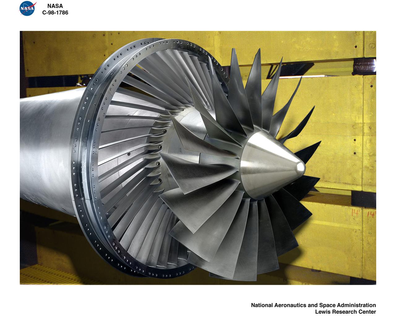
ALLISON DUCTED FAN IN 9X15 FOOT LOW SPEED WIND TUNNEL
ALLISON DUCTED FAN IN 9X15 FOOT LOW SPEED WIND TUNNEL
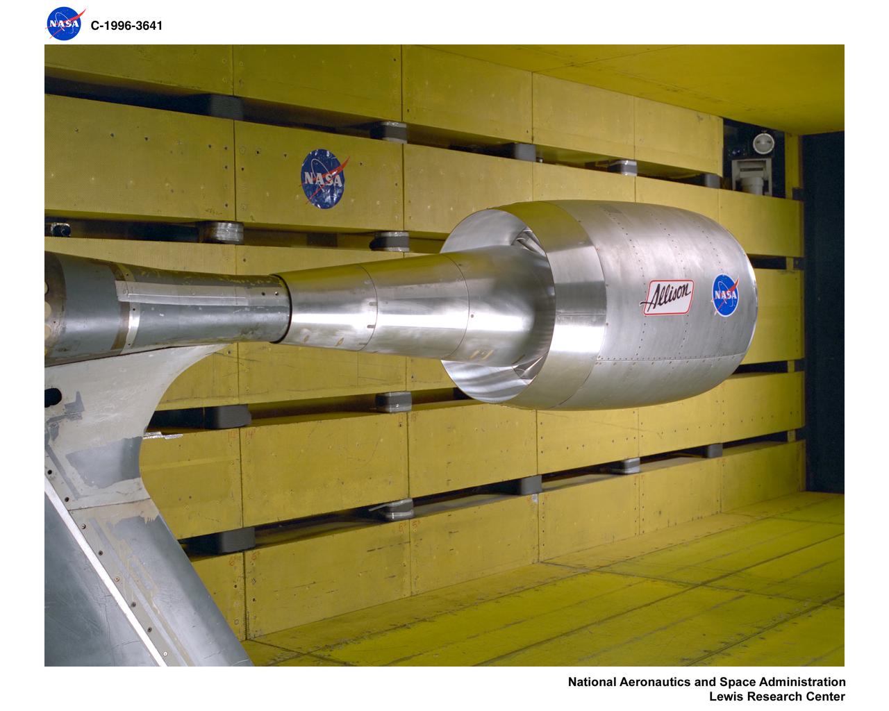
ALLISON DUCTED FAN IN 9X15 FOOT LOW SPEED WIND TUNNEL
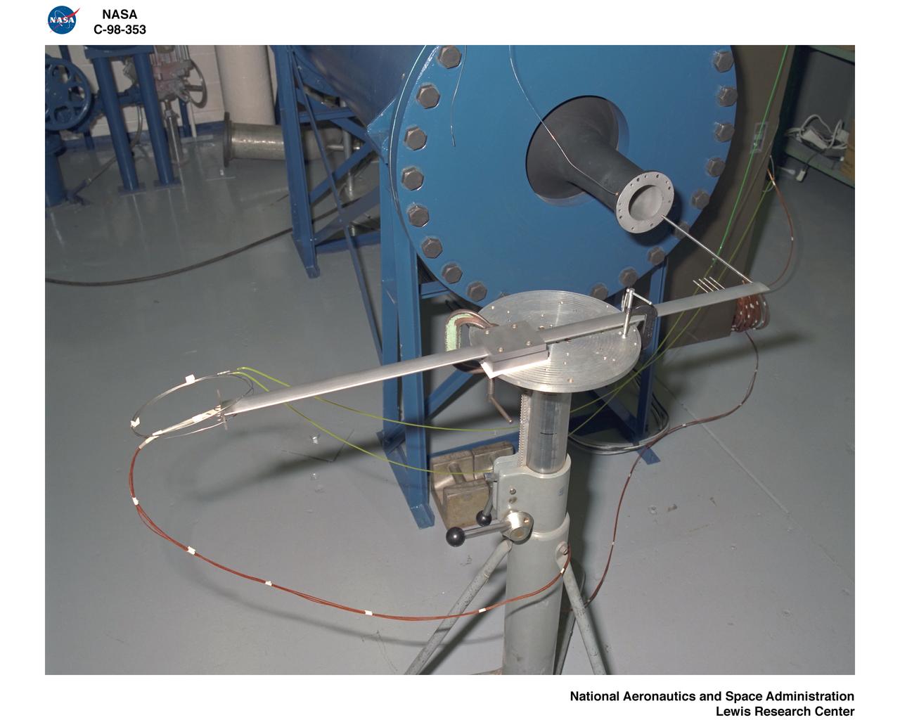
CALIBRATION OF THE 9X15 FOOT LOW SPEED WIND TUNNEL TEST SECTION RAKES
N-231 Low Speed Wind Tunnel Laser Doppler Velocemeter and Helium Neon Laser
N-231 Low Speed Wind Tunnel Laser Doppler Velocemeter and Helium Neon Laser
Supersonic Short Take Off Vertical Landing Hot Gas Ingestion Model Testing in the 9x15-foot Low Speed Wind Tunnel, LSWT
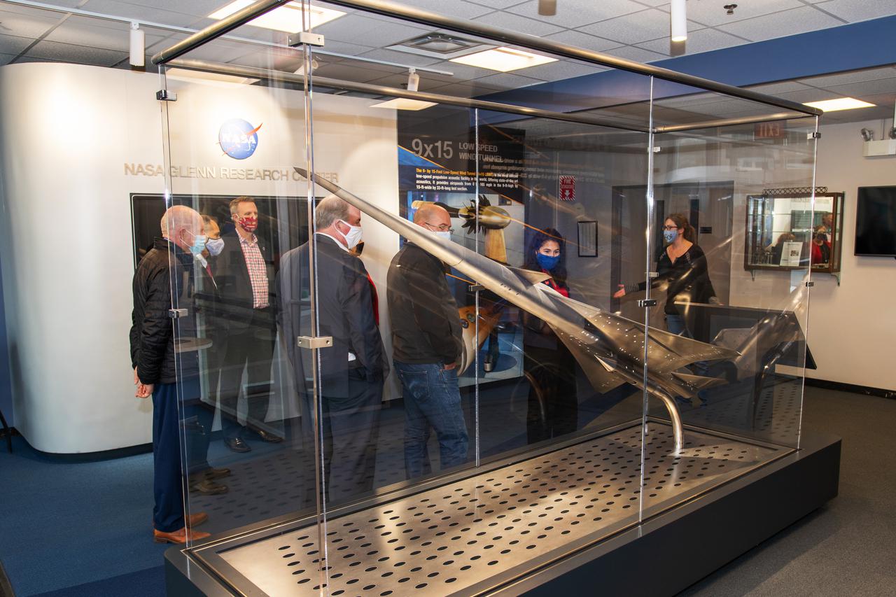
Tour of the Glenn Research Center’s 8x6 Supersonic wind tunnel and the 9x15 Low Speed wind tunnels by senior management. The tour group is the Dayton Development Coalition representing JobsOhio. Photo was taken in the lobby of building 54 with the display of the QueSST (Quiet, Efficient SuperSonic Transport) model in the foreground.
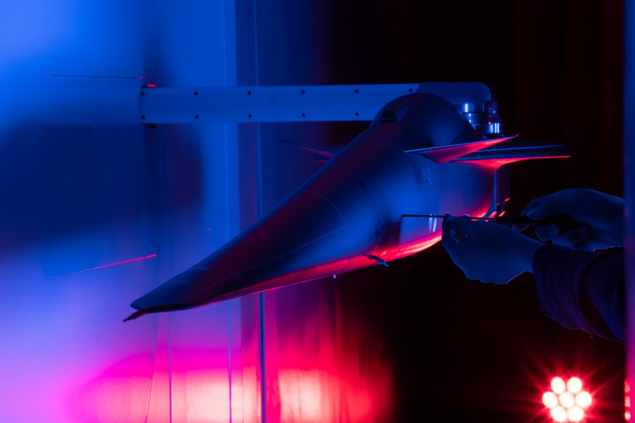
Event: Forebody and Nose - Windtunnel Testing A technician works on the X-59 model during testing in the low-speed wind tunnel at Lockheed Martin Skunk Works in Palmdale, California. These tests gave the team measurements of wind flow angle around the aircraft’s nose and confirmed computer predictions made using computational fluid dynamics (CFD) software tools. The data will be fed into the aircraft flight control system to tell the pilot the aircraft’s altitude, speed, and angle. This is part of NASA’s Quesst mission which plans to help enable supersonic air travel over land.
LSAWT\Twin Jet Test with HWB Model\JEDA Measurements Low Speed Aeroacoustic Wind Tunnel\Twin Jet Model System \Hybrid Wing Model Installed\ Measurement Technique: Jet Directional Array (JEDA)
3/4 front view of model with flaps up. V/STOL Aircraft: Wind tunnel investigation of rotating cylinder applied to training edge flaps for high lift & low-speed control.
3/4 rear view of model with flaps down. V/STOL Aircraft: Wind tunnel investigation of rotating cylinder applied to training edge flaps for high lift & low-speed control.
40x80x120 Foot Wind Tunnel at NASA's Ames Research Center Laser Velocimeter (LV) Long Range System. Requesting Organization: Low Speed Aircraft Photographed on May 18, 1983
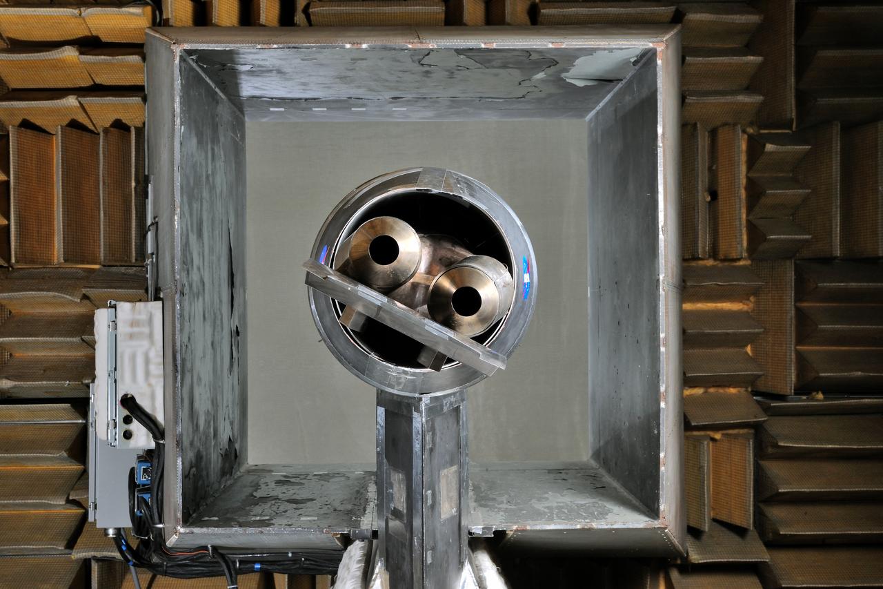
LSAWT\Twin Jet Test with HWB Model\JEDA Measurements Low Speed Aeroacoustic Wind Tunnel\Twin Jet Model System \Hybrid Wing Model Installed\ Measurement Technique: Jet Directional Array (JEDA)
LSAWT\Twin Jet Test with HWB Model\JEDA Measurements Low Speed Aeroacoustic Wind Tunnel\Twin Jet Model System \Hybrid Wing Model Installed\ Measurement Technique: Jet Directional Array (JEDA)

3/4 rear view of model with flaps down with Cecil E. MacDonald. V/STOL Aircraft: Wind tunnel investigation of rotating cylinder applied to training edge flaps for high lift & low-speed control.
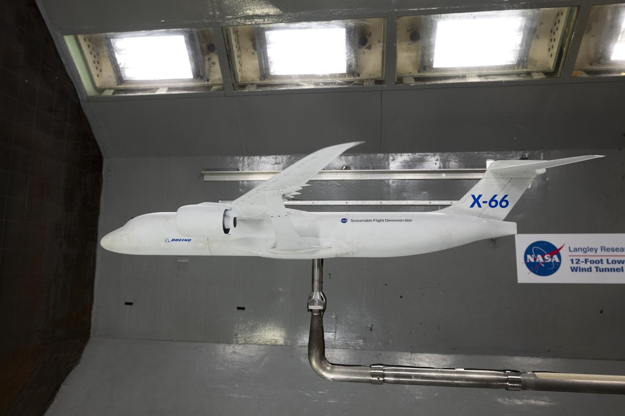
A model of the X-66 aircraft with a wingspan of almost 6 feet was placed in the 12-Foot Low-Speed Wind Tunnel at NASA’s Langley Research Center in Hampton, Virginia on October 30, 2024. During the tests, the team captured measurements of forces such as lift and drag over many aerodynamic configurations and flight conditions.
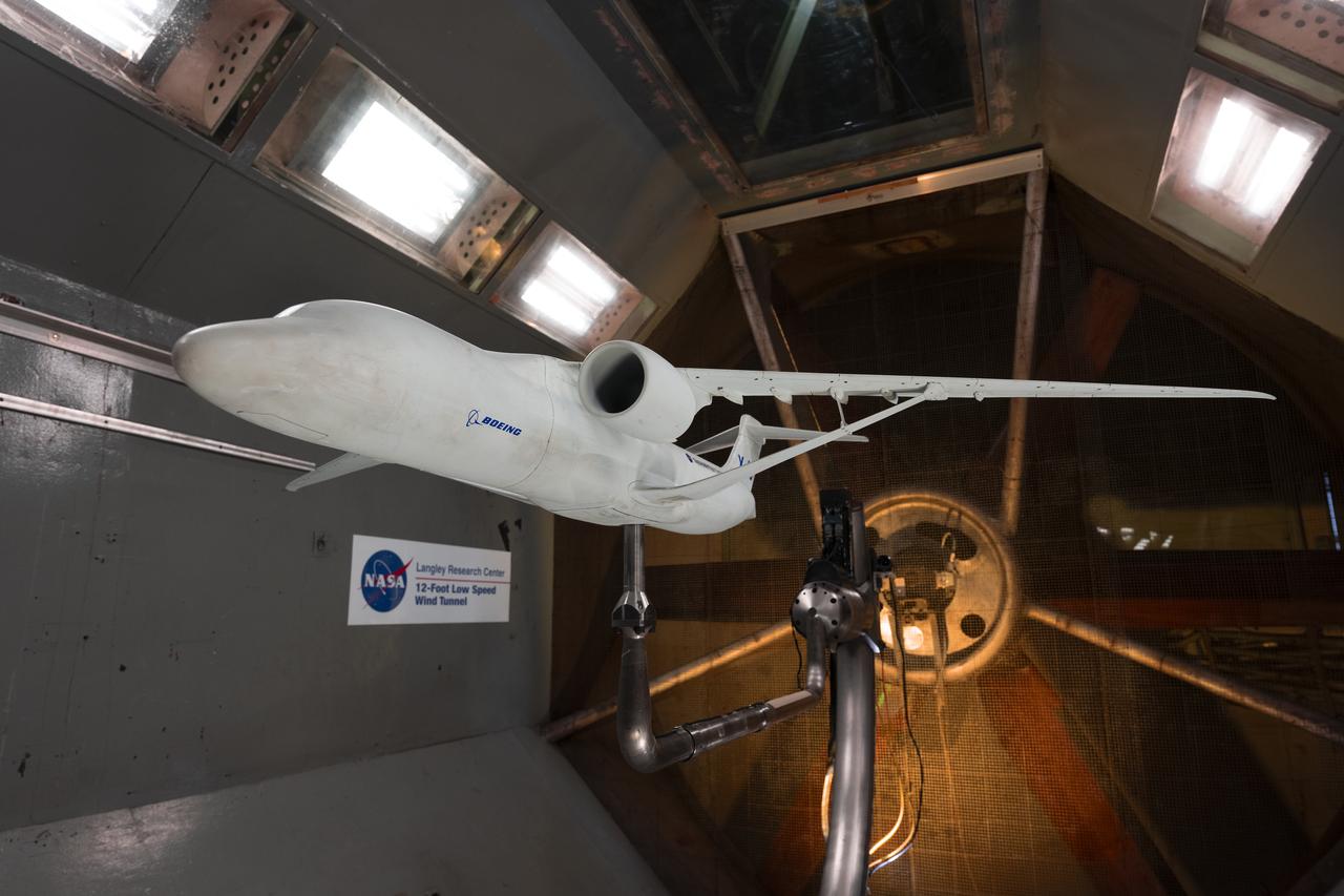
A model of the X-66 aircraft with a wingspan of almost 6 feet was placed in the 12-Foot Low-Speed Wind Tunnel at NASA’s Langley Research Center in Hampton, Virginia on October 30, 2024. During the tests, the team captured measurements of forces such as lift and drag over many aerodynamic configurations and flight conditions.
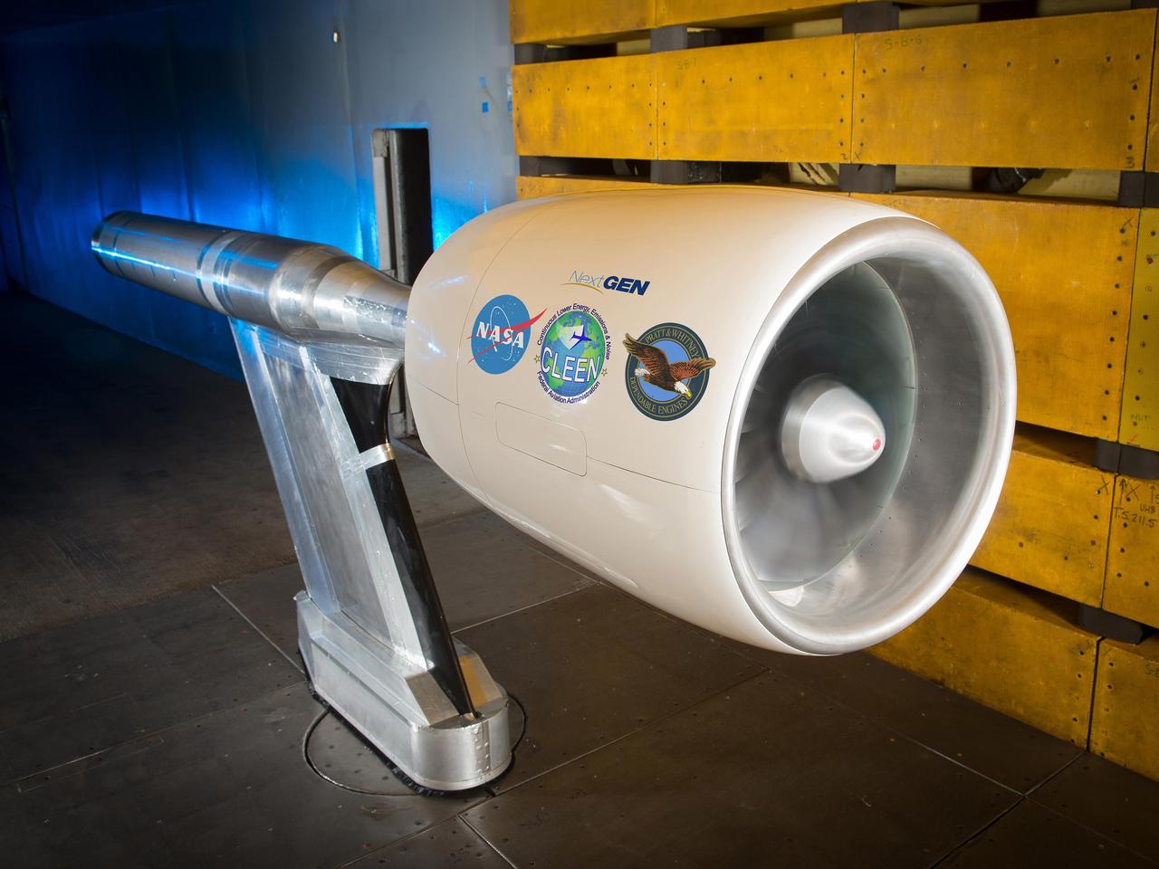
NASA’s Environmentally Responsible Aviation Project, in collaboration with the Federal Aviation Administration (FAA) and Pratt & Whitney, completed testing of an Ultra High Bypass Ratio Turbofan Model in the 9’ x 15’ Low Speed Wind Tunnel at NASA Glenn Research Center. The fan model is representative of the next generation of efficient and quiet Ultra High Bypass Ratio Turbofan Engine designs.

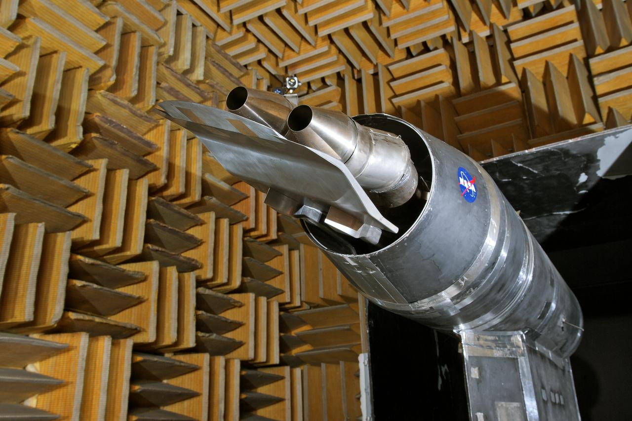
National Aeronautics and Space Administration (NASA) researcher John Carpenter inspects an aircraft model with a four-fan thrust reverser which would be studied in the 9- by 15-Foot Low Speed Wind Tunnel at the Lewis Research Center. Thrust reversers were introduced in the 1950s as a means for slowing high-speed jet aircraft during landing. Engineers sought to apply the technology to Vertical and Short Takeoff and Landing (VSTOL) aircraft in the 1970s. The new designs would have to take into account shorter landing areas, noise levels, and decreased thrust levels. A balance was needed between the thrust reverser’s efficiency, its noise generation, and the engine’s power setting. This model underwent a series of four tests in the 9- by 15-foot tunnel during April and May 1974. The model, with a high-wing configuration and no tail, was equipped with four thrust-reverser engines. The investigations included static internal aerodynamic tests on a single fan/reverser, wind tunnel isolated fan/reverser thrust tests, installation effects on a four-fan airplane model in a wind tunnel, and single reverser acoustic tests. The 9-by 15 was built inside the return leg of the 8- by 6-Foot Supersonic Wind Tunnel in 1968. The facility generates airspeeds from 0 to 175 miles per hour to evaluate the aerodynamic performance and acoustic characteristics of nozzles, inlets, and propellers, and investigate hot gas re-ingestion of advanced VSTOL concepts. John Carpenter was a technician in the Wind Tunnels Service Section of the Test Installations Division.
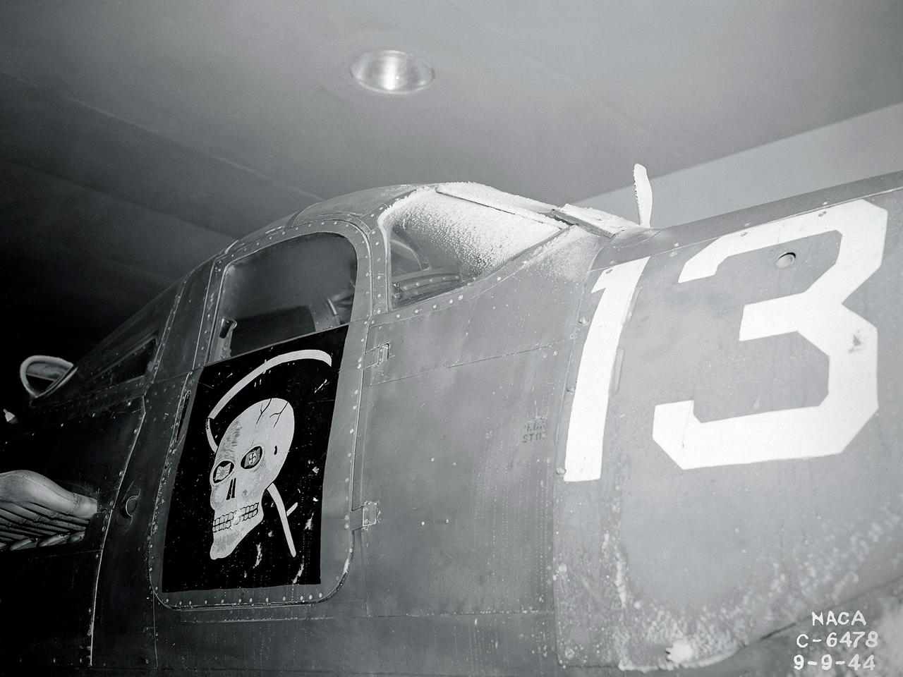
A Bell P-39 Airacobra in the NACA Aircraft Engine Research Laboratory’s Icing Research Tunnel for a propeller deicing study. The tunnel, which began operation in June 1944, was built to study the formation of ice on aircraft surfaces and methods of preventing or eradicating that ice. Ice buildup adds extra weight to aircraft, effects aerodynamics, and sometimes blocks airflow through engines. NACA design engineers added the Icing Research Tunnel to the new AERL’s original layout to take advantage of the massive refrigeration system being constructed for the Altitude Wind Tunnel. The Icing Research Tunnel is a closed-loop atmospheric wind tunnel with a 6- by 9-foot test section. The tunnel can produce speeds up to 300 miles per hour and temperatures from about 30 to –45⁰ F. During World War II AERL researchers analyzed different ice protection systems for propeller, engine inlets, antennae, and wings in the icing tunnel. The P-39 was a vital low-altitude pursuit aircraft of the US during the war. NACA investigators investigated several methods of preventing ice buildup on the P-39’s propeller, including the use of internal and external electrical heaters, alcohol, and hot gases. They found that continual heating of the blades expended more energy than the aircraft could supply, so studies focused on intermittent heating. The results of the wind tunnel investigations were then compared to actual flight tests on aircraft.
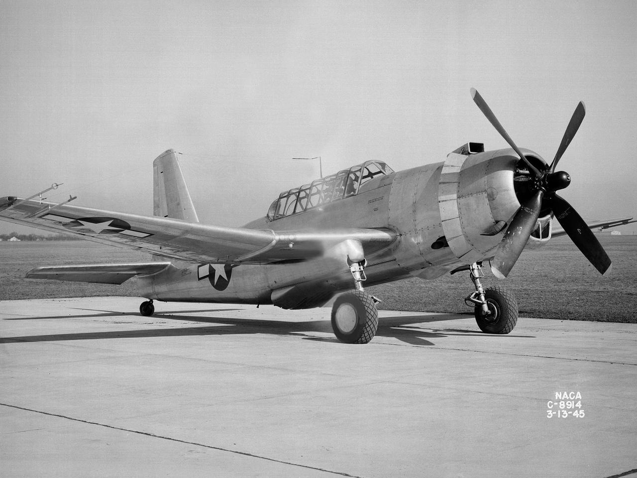
A Bell P-39 Airacobra in the NACA Aircraft Engine Research Laboratory’s Icing Research Tunnel for a propeller deicing study. The tunnel, which began operation in June 1944, was built to study the formation of ice on aircraft surfaces and methods of preventing or eradicating that ice. Ice buildup adds extra weight to aircraft, effects aerodynamics, and sometimes blocks airflow through engines. NACA design engineers added the Icing Research Tunnel to the new AERL’s original layout to take advantage of the massive refrigeration system being constructed for the Altitude Wind Tunnel. The Icing Research Tunnel is a closed-loop atmospheric wind tunnel with a 6- by 9-foot test section. The tunnel can produce speeds up to 300 miles per hour and temperatures from about 30 to -45⁰ F. During World War II AERL researchers analyzed different ice protection systems for propeller, engine inlets, antennae, and wings in the icing tunnel. The P-39 was a vital low-altitude pursuit aircraft of the US during the war. NACA investigators investigated several methods of preventing ice buildup on the P-39’s propeller, including the use of internal and external electrical heaters, alcohol, and hot gases. They found that continual heating of the blades expended more energy than the aircraft could supply, so studies focused on intermittent heating. The results of the wind tunnel investigations were then compared to actual flight tests on aircraft.
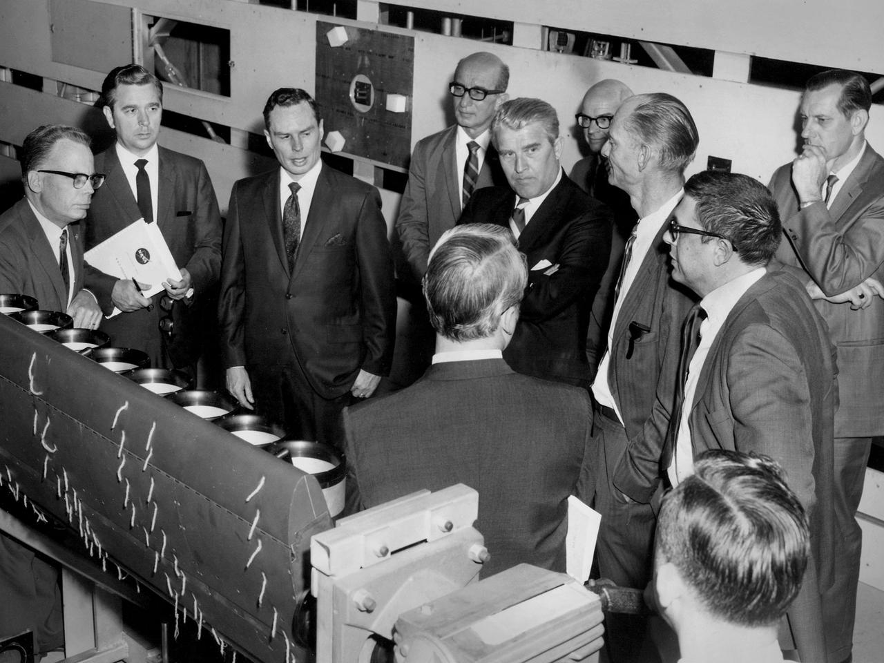
Werner von Braun, National Aeronautics and Space Administration (NASA) Deputy Associate Administrator for Planning, among a group from Headquarters touring the Lewis Research Center in Cleveland, Ohio. Lewis Special Projects Chief Newell Sanders, left, describes a Short Takeoff and Landing wing-propulsion model. Lewis had recently converted the return leg of its 8- by 6-Foot Supersonic Wind Tunnel into the 9- by 15-Foot Low Speed Wind Tunnel to investigate Vertical and Short Takeoff and Landing propulsion systems. Gathered from the left near Sanders are James Daniels, Headquarters Executive Secretary; Oran Hicks, Acting Associate Administrator for the Headquarters Office of Advanced Research and Technology; Eugene Manganiello, Lewis Deputy Director; von Braun; Dr. Walter Olson, Lewis Assistant Director; Bruce Lundin, Lewis Director and Dr. Bernard Lubarsky, Lewis Assistant Director. Just months before this photograph, NASA asked von Braun to give up his post as Director of the Marshall Space Flight Center after nearly ten years in order to head up the strategic planning effort for the agency from Washington DC. Von Braun retired from NASA two years later.
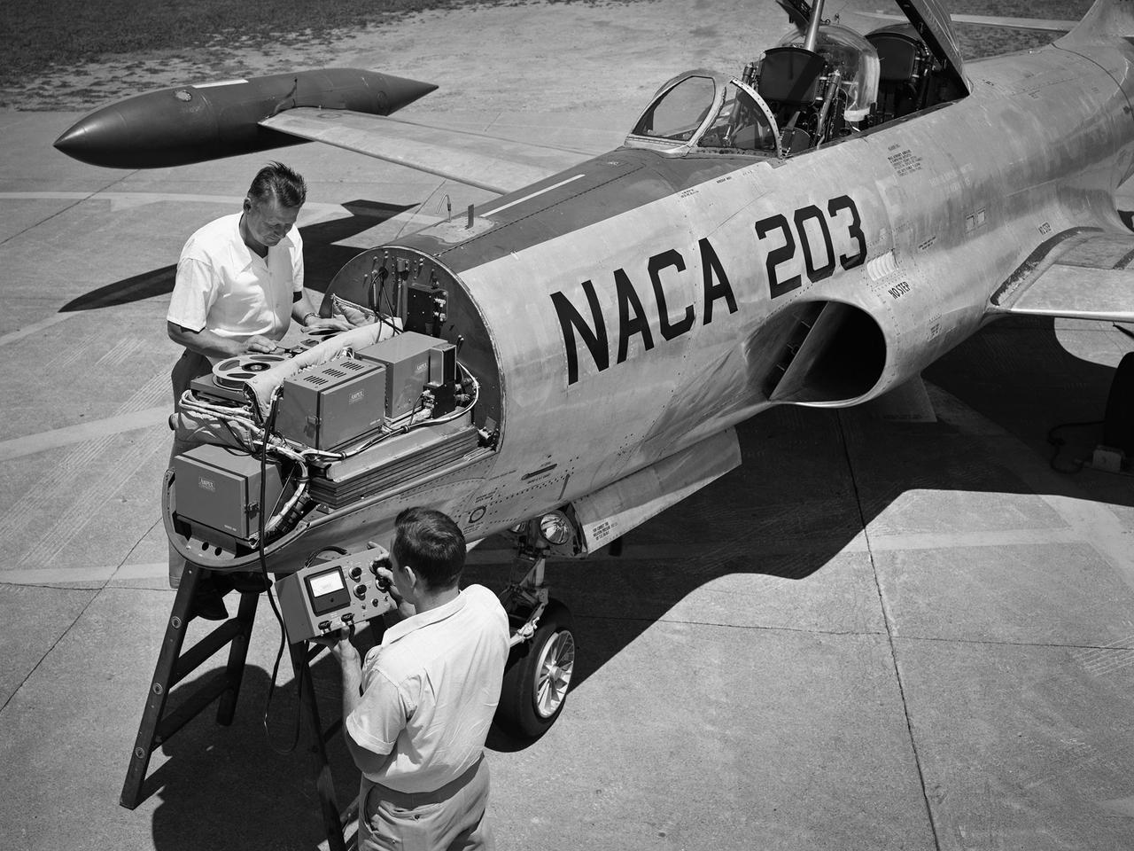
A Lockheed F-94B Starfire being equipped with an audio recording machine and sensors at the National Advisory Committee for Aeronautics (NACA) Lewis Flight Propulsion Laboratory. The NACA was investigating the acoustic effects caused by the engine’s nozzle and the air flowing along the fuselage. Airline manufacturers would soon be introducing jet engines on their passenger aircraft, and there was concern regarding the noise levels for both the passengers and public on the ground. NACA Lewis conducted a variety of noise reduction studies in its wind tunnels, laboratories, and on a F2H-2B Banshee aircraft. The F2H-2B Banshee’s initial test flights in 1955 and 1956 measured the noise emanating directly from airflow over the aircraft’s surfaces, particularly the wings. This problem was particularly pronounced at high subsonic speeds. The researchers found the majority of the noise occurred in the low and middle octaves. These investigations were enhanced with a series of flights using the F-94B Starfire. The missions measured wall-pressure, turbulence fluctuations, and mean velocity profiles. Mach 0.3 to 0.8 flights were flown at altitudes of 10,000, 20,000, and 30,000 feet with microphones mounted near the forward fuselage and on a wing. The results substantiated the wind tunnel findings. This photograph shows the tape recorder being installed in the F-94B’s nose.

Photo of Sue Grafton taken in advance of the Flight Dynamic Research Facility's (FDRF) ribbon cutting. Sue started as a researcher for the N.A.C.A. and worked in the vertical spin tunnel (VST). She has since worked in the 30x60 full-scale tunnel for many years before its closure and then returned to VST and 12ft (NASA’s oldest operational wind tunnels). She will also be onboard for the commissioning of the FDRF, NASA’s newest wind tunnel.

Sue Grafton, NASA engineer poses in advance of the Flight Dynamic Research Facility's (FDRF) grand opening. Sue started as a researcher for the N.A.C.A. and worked in the vertical spin tunnel (VST). She has since worked in the 30x60 full-scale tunnel for many years before its closure and then returned to VST and 12ft (NASA’s oldest operational wind tunnels). She will also be onboard for the commissioning of the FDRF, NASA’s newest wind tunnel.
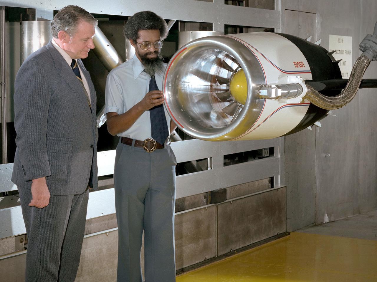
Center Director John McCarthy, left, and researcher Al Johns pose with a one-third scale model of a Grumman Aerospace tilt engine nacelle for Vertical and Short Takeoff and Landing (V/STOL) in the 9- by 15-Foot Low Speed Wind Tunnel at the National Aeronautics and Space Administration (NASA) Lewis Research Center. Lewis researchers had been studying tilt nacelle and inlet issues for several years. One area of concern was the inlet flow separation during the transition from horizontal to vertical flight. The separation of air flow from the inlet’s internal components could significantly stress the fan blades or cause a loss of thrust. In 1978 NASA researchers Robert Williams and Al Johns teamed with Grumman’s H.C. Potonides to develop a series of tests in the Lewis 9- by 15-foot tunnel to study a device designed to delay the flow separation by blowing additional air into the inlet. A jet of air, supplied through the hose on the right, was blown over the inlet surfaces. The researchers verified that the air jet slowed the flow separation. They found that the blowing on boundary layer control resulted in a doubling of the angle-of-attack and decreases in compressor blade stresses and fan distortion. The tests were the first time the concept of blowing air for boundary layer control was demonstrated. Boundary layer control devices like this could result in smaller and lighter V/STOL inlets.
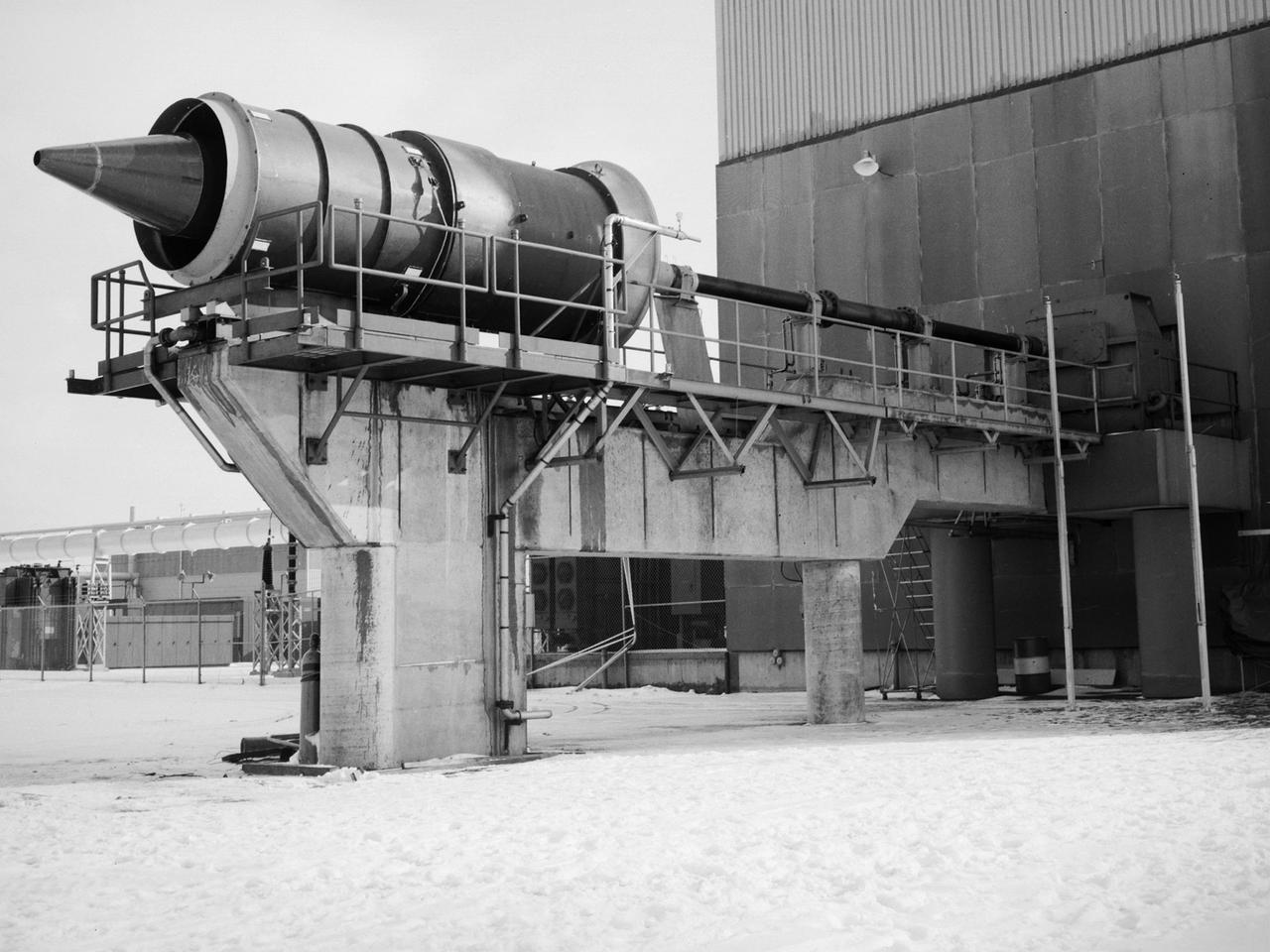
The Fan Noise Test Facility built at the Lewis Research Center to obtain far-field noise data for the National Aeronautics and Space Administration (NASA) and General Electric Quiet Engine Program. The engine incorporated existing noise reduction methods into an engine of similar power to those that propelled the Boeing 707 or McDonnell-Douglas DC-8 airliner. The new the low-bypass ratio turbofan engines of the 1960s were inherently quieter than their turbojet counterparts, researchers had a better grasp of the noise generation problem, and new acoustic technologies had emerged. Lewis contracted General Electric in 1969 to build and aerodynamically test three experimental engines with 72-inch diameter fans. The engines were then brought to Lewis and tested with an acoustically treated nacelle. This Fan Noise Test Facility was built off of the 10- by 10-Foot Supersonic Wind Tunnel’s Main Compressor and Drive Building. Lewis researchers were able to isolate the fan’s noise during these initial tests by removing the core of the engine. The Lewis test rig drove engines to takeoff tip speeds of 1160 feet per second. The facility was later used to test a series of full-scale model fans and fan noise suppressors to be used with the quiet engine. NASA researchers predicted low-speed single-stage fans without inlet guide vanes and with large spacing between rotors and stators would be quieter. General Electric modified a TF39 turbofan engine by removing the the outer protion of the fan and spacing the blade rows of the inner portion. The tests revealed that the untreated version of the engine generated less noise than was anticipated, and the acoustically treated nacelle substantially reduced engine noise.
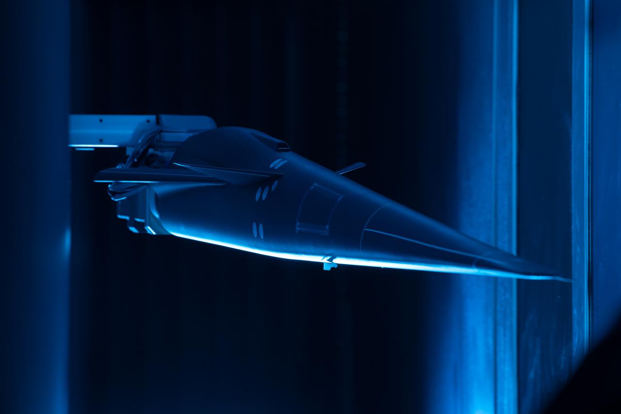
Event: Forebody and Nose - Windtunnel Testing A model of the X-59 forebody is shown in the Lockheed Martin Skunk Works’ wind tunnel in Palmdale, California. These tests gave the team measurements of wind flow angle around the aircraft’s nose and confirmed computer predictions made using computational fluid dynamics (CFD) software tools. The data will be fed into the aircraft flight control system to tell the pilot the aircraft’s altitude, speed and angle. This is part of NASA’s Quesst mission which plans to help enable supersonic air travel over land.
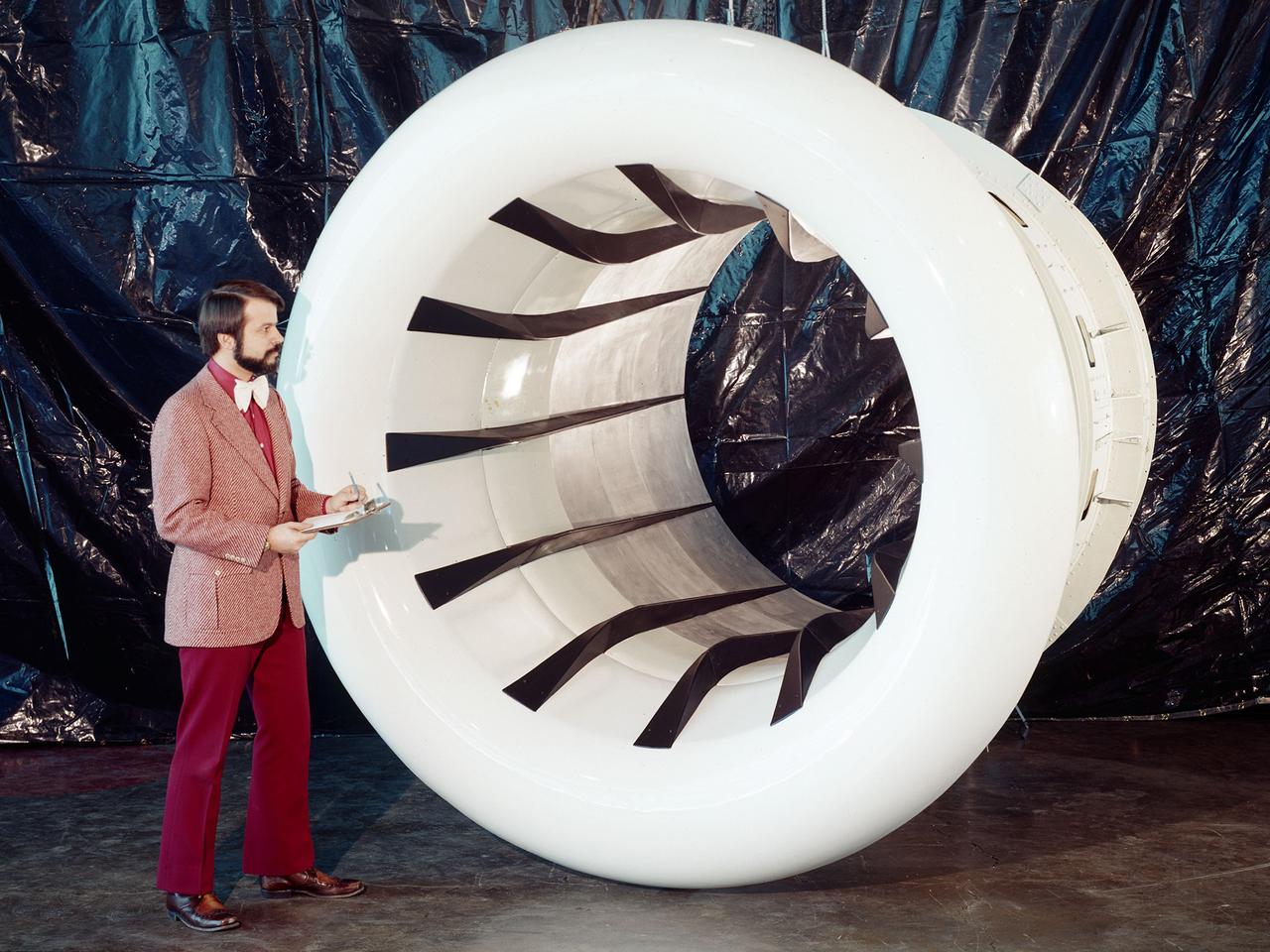
Brent Miller, of the V/STOL and Noise Division at the National Aeronautics and Space Administration (NASA) Lewis Research Center, poses with a sonic inlet for the NASA Quiet Engine Program. NASA Lewis had first investigated methods for reducing aircraft engine noise in the mid-1950s. Those efforts were resurrected and expanded in the late 1960s. The researchers found that the use of a sonic, or high-throat-Mach-number, inlet was effective at reducing the noise from the engine inlet. The device accelerated the inlet air to near-sonic speeds which kept the forward moving sound waves away from the inlet. The device also deflected the sound waves into the wall to further reduce the noise. NASA Lewis researchers tested models of the sonic inlet in their 9- by 15-Foot Low Speed Wind Tunnel. They found that the general level of aerodynamic performance was good. The tests during simulated takeoff and landing conditions demonstrated the sonic inlet’s ability to provide good aerodynamic and acoustic performance The researchers then successfully tested two full-scale sonic inlet designs, one from Pratt and Whitney and one from General Electric, with fans. A full-scale engine was installed on a thrust stand to determine the sonic inlet’s effect on the engine’s performance. The amount of noise reduction increased as the inlet flow velocity increased, but the full-scale tests did not produce as great a decrease in noise as the earlier small-scale tests.