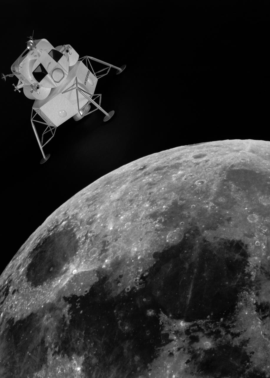
Artist rendering of the lunar excursion module approaching the moon. The lunar module design underwent gradual evolution from the first configuration proposed by Grumman in 1962. This model is a 1964 rendering. Langley had the task of building a simulator for the astronauts to practice lunar landings. The configuration of the initial vehicle used with the Lunar Landing Research Facility (LLRF) was changed in 1967 to more accurately reflect the standing position of the astronauts, cockpit arrangement, instrumentation, controls and field of view.
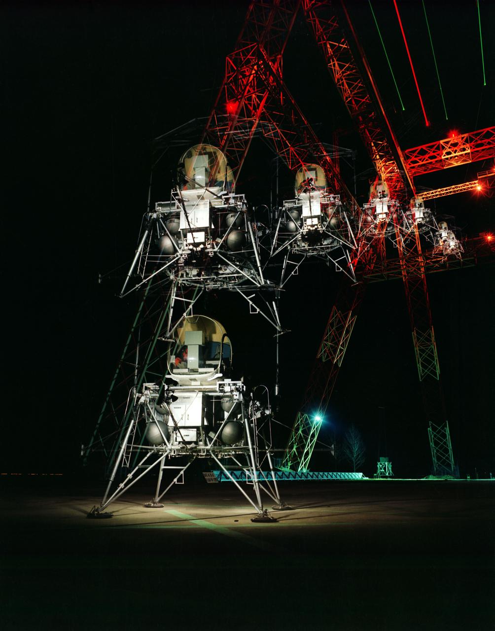
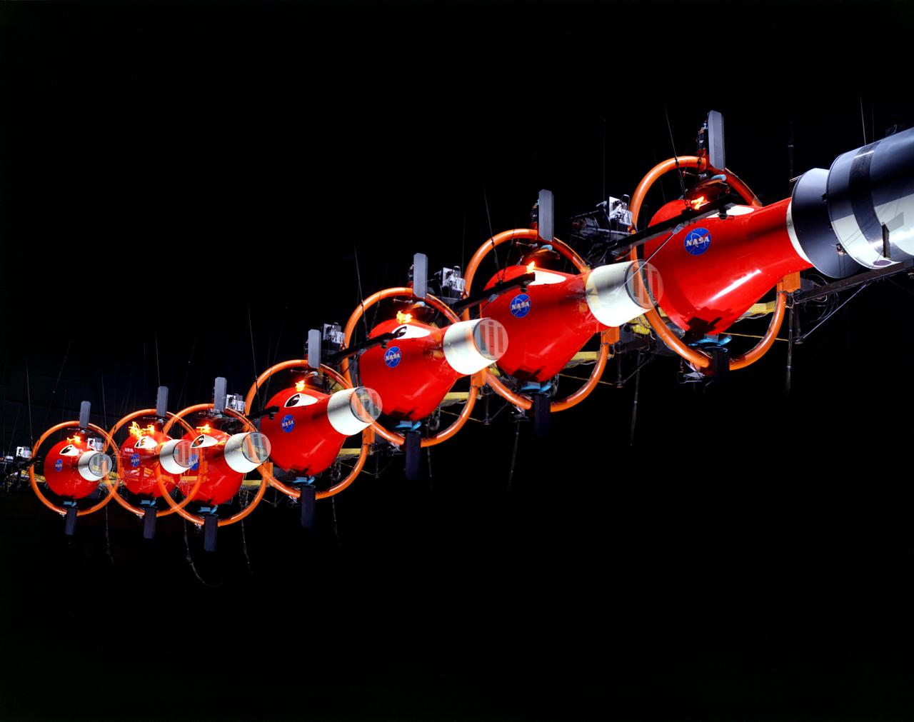
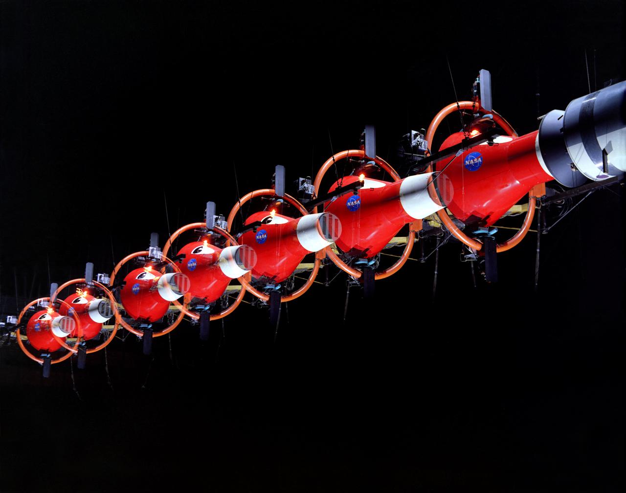
During a nighttime training session, a multiple exposure captures the movement of the Lunar Excursion Module Simulator (LEMS). The LEMS was a manned vehicle used to familiarize the Apollo astronauts with the handling characteristics of lunar-landing type vehicle. The Apollo Program is best known for the astronaut Neal Armstrong s first step on the Moon July 20, 1969. In its earliest test period, the LEMS featured a helicopter crew cabin atop the lunar landing module. Later, the helicopter crew cabin was replaced with a stand-up rectangular cabin which was more efficient for controlling maneuvers and for better viewing by the pilot. The vehicle was designed at Langley Research Center in Hampton, VA. This multiple exposure shows a simulated Moon landing of the (LEMS) trainer at Langley s Lunar Landing Research Facility. -- Photograph published in Winds of Change, 75th Anniversary NASA publication (page 70), by James Shultz. Also published in " A Century at Langley" by Joseph Chambers, pg. 93.
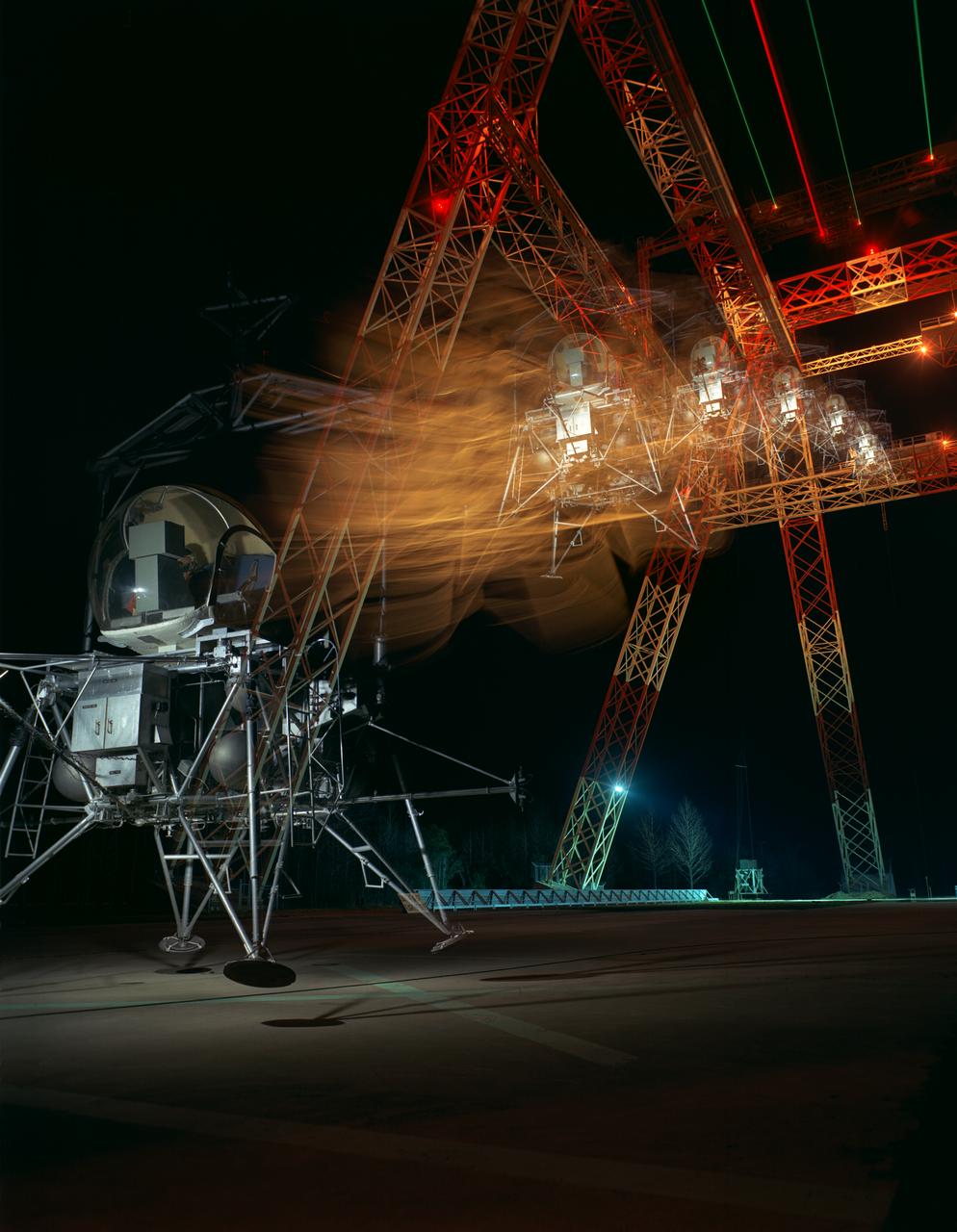
During a nighttime training session, a multiple exposure captures the movement of the Lunar Excursion Module Simulator (LEMS). The LEMS was a manned vehicle used to familiarize the Apollo astronauts with the handling characteristics of lunar-landing type vehicle. The Apollo Program is best known for the astronaut Neal Armstrong s first step on the Moon July 20, 1969. In its earliest test period, the LEMS featured a helicopter crew cabin atop the lunar landing module. Later, the helicopter crew cabin was replaced with a stand-up rectangular cabin which was more efficient for controlling maneuvers and for better viewing by the pilot. The vehicle was designed at Langley Research Center in Hampton, VA. This multiple exposure shows a simulated Moon landing of the (LEMS) trainer at Langley s Lunar Landing Research Facility. -- Photograph published in Winds of Change, 75th Anniversary NASA publication (page 70), by James Shultz. Also published in " A Century at Langley" by Joseph Chambers, pg. 93.
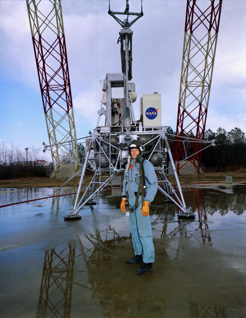
Neil Armstrong with the Lunar Excursion Module (LEM). Caption: "Not long after this photo was taken in front of the Lunar Landing Research Facility, astronaut Neil Armstrong became the first human to step upon the surface of the Moon." Photograph published in Winds of Change, 75th Anniversary NASA publication, by James Schultz, page 91. Also published in " A Century at Langley" by Joseph Chambers, pg. 95
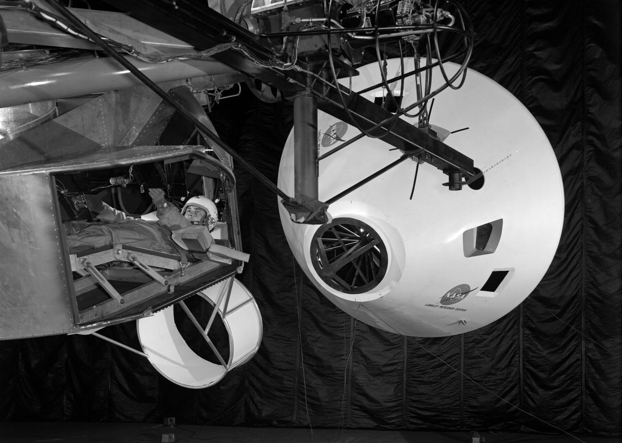
Originally the Rendezvous was used by the astronauts preparing for Gemini missions. The Rendezvous Docking Simulator was then modified and used to develop docking techniques for the Apollo program. The pilot is shown maneuvering the LEM into position for docking with a full-scale Apollo Command Module. From A.W. Vogeley, Piloted Space-Flight Simulation at Langley Research Center, Paper presented at the American Society of Mechanical Engineers, 1966 Winter Meeting, New York, NY, November 27 - December 1, 1966. The Rendezvous Docking Simulator and also the Lunar Landing Research Facility are both rather large moving-base simulators. It should be noted, however, that neither was built primarily because of its motion characteristics. The main reason they were built was to provide a realistic visual scene. A secondary reason was that they would provide correct angular motion cues (important in control of vehicle short-period motions) even though the linear acceleration cues would be incorrect. Apollo Rendezvous Docking Simulator: Langley s Rendezvous Docking Simulator was developed by NASA scientists to study the complex task of docking the Lunar Excursion Module with the Command Module in Lunar orbit.
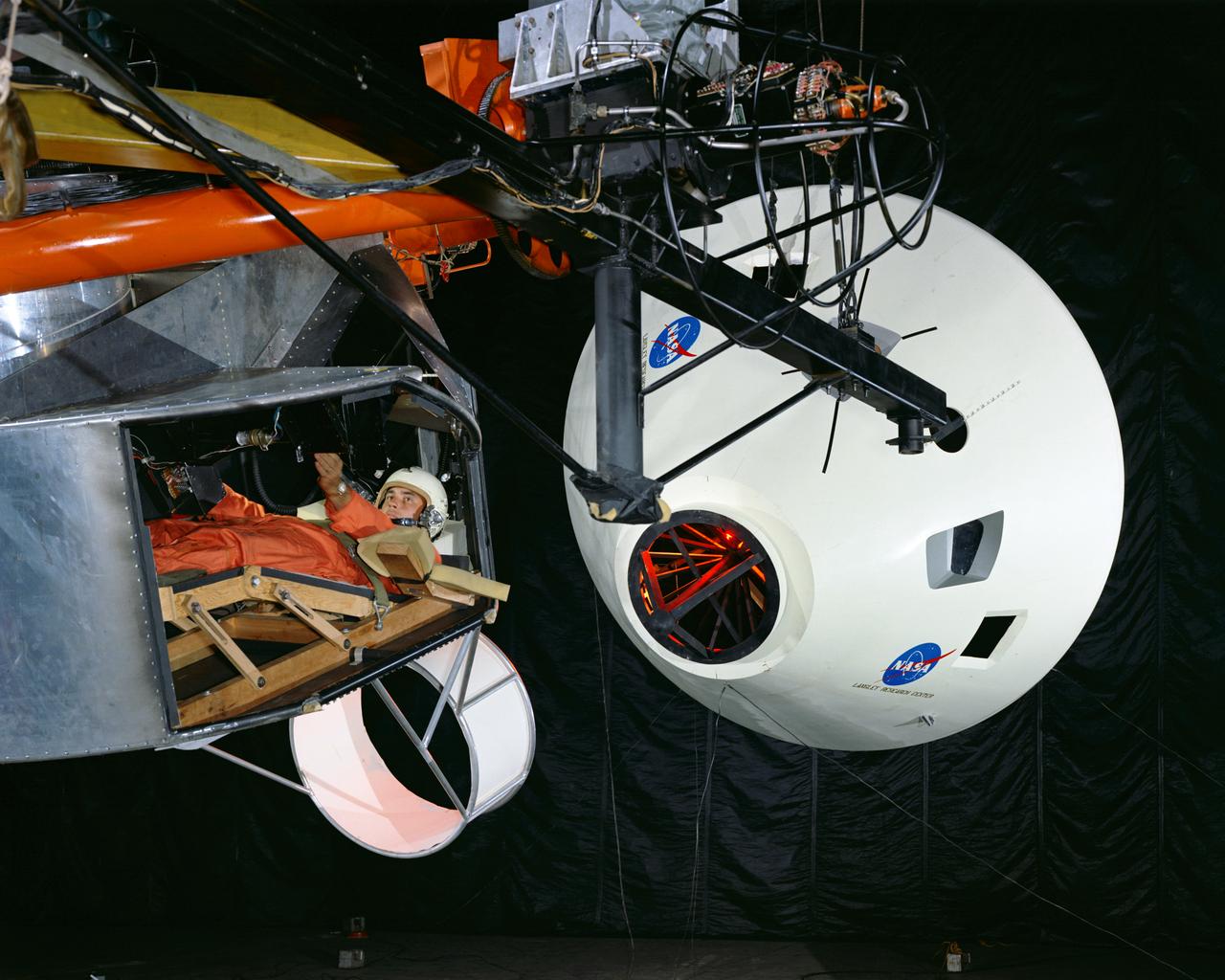
Simulator for Apollo Rendezvous Lunar Excursion Module (LEM)
Simulator for Apollo Rendezvous Lunar Excursion Module (LEM)
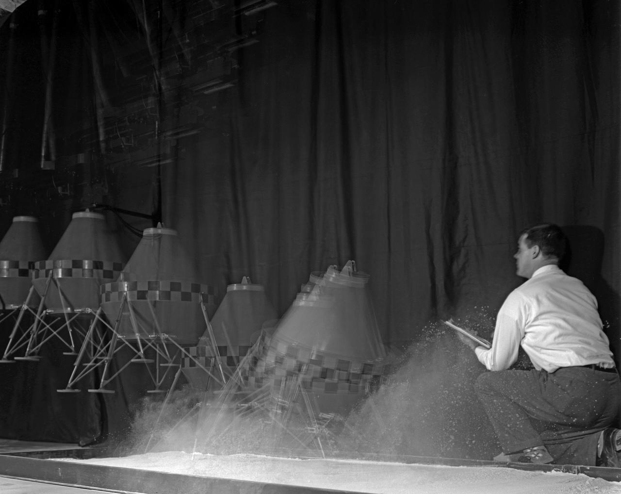
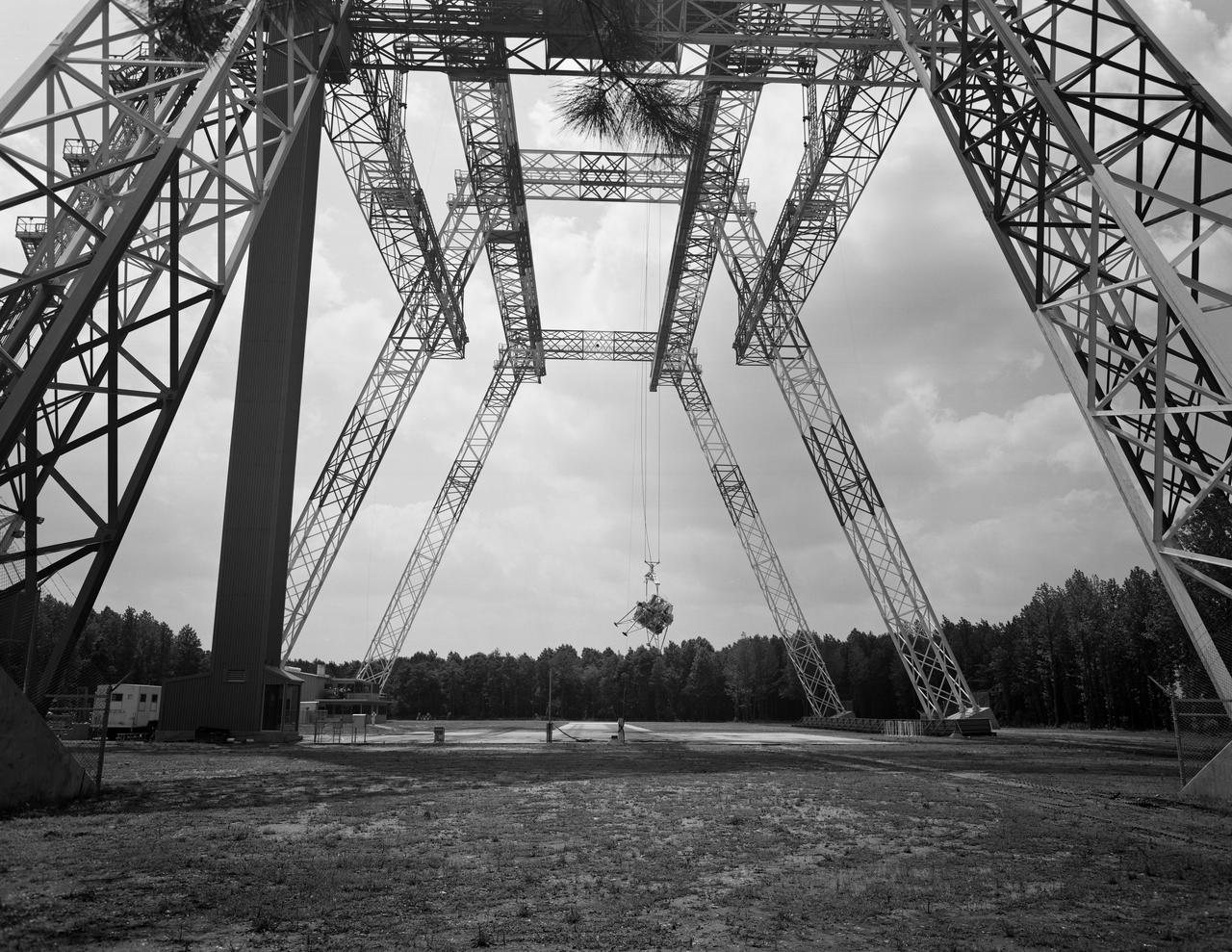
Multiple exposure of a test with a prototype Lunar Excursion Module. This test was one of many conducted at Langley of the structural dynamics of lunar landing.
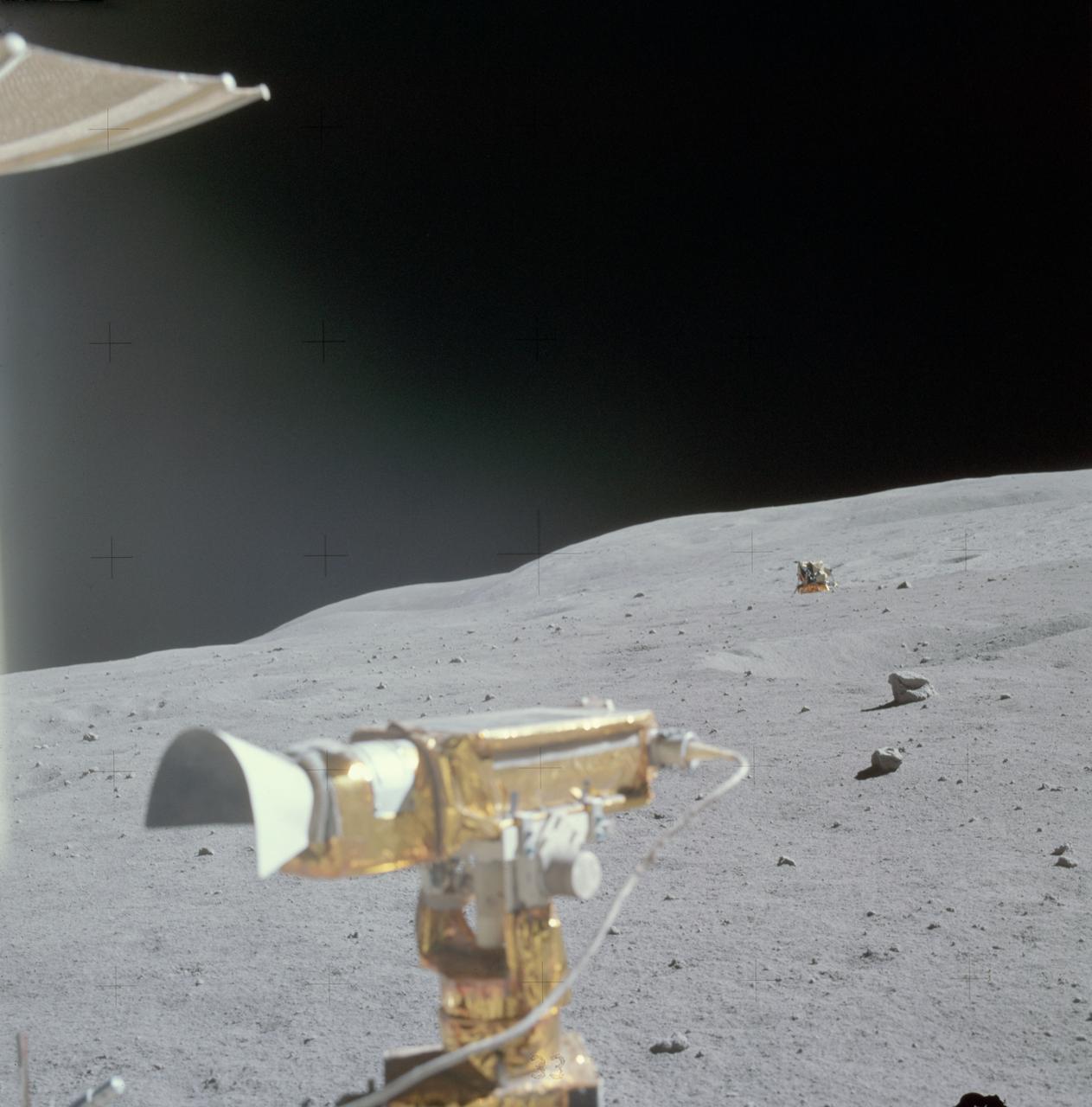
AS16-115-18549 (22 April 1972) --- The Apollo 16 Lunar Module (LM) "Orion" is photographed from a distance by astronaut Charles M. Duke Jr., lunar module pilot, aboard the moving Lunar Roving Vehicle (LRV). Astronauts Duke and John W. Young, commander, were returning from their excursion to Stone Mountain during the second Apollo 16 extravehicular activity (EVA). The RCA color television camera mounted on the LRV is in the foreground. A portion of the LRV's high-gain antenna is at top left. Smoky Mountain rises behind the LM in this north-looking view at the Descartes landing site. While astronauts Young and Duke descended in the "Orion" to explore the Descartes highlands landing site on the moon, astronaut Thomas K. Mattingly II, command module pilot, remained with the Command and Service Modules (CSM) "Casper" in lunar orbit.
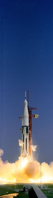
A/S 201 was launched from the Kennedy Space Center Launch Complex 34 at 11:12 a.m., 02/26/1966. The instrumented Apollo Command and Service Module, and, a spacecraft Lunar Excursion Module Adapter, was successfully launched on the unmanned suborbital mission by the Saturn 1B to check spacecraft launch vehicle mechanical compatibility and to test the spacecraft heat shield in a high-velocity re-entry mode. CAPE KENNEDY, FL
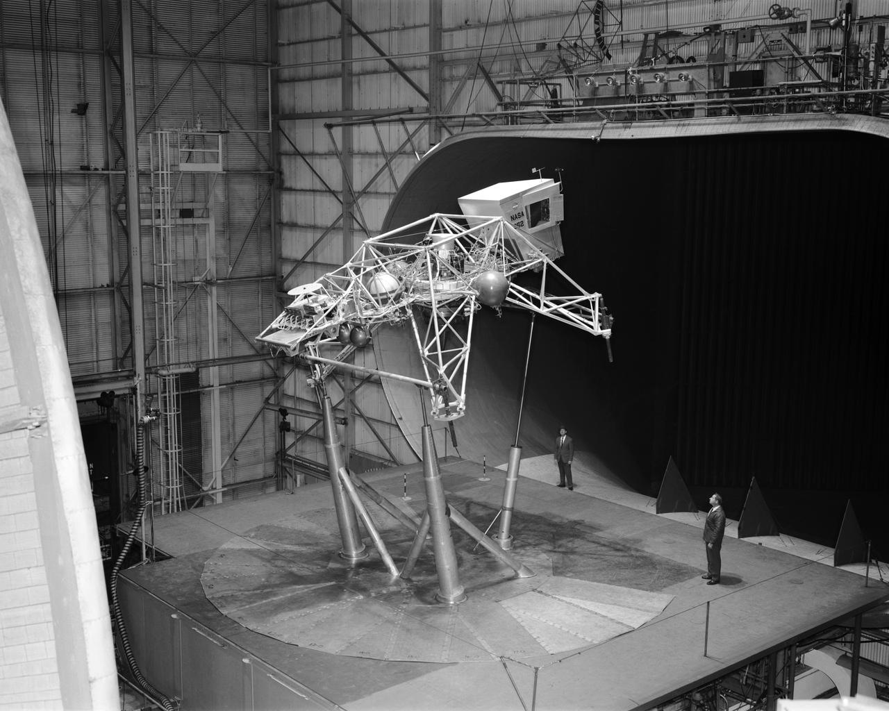
Concept model of the Lunar Excursion Module tested in the Full-Scale wind tunnel. -- Published in James R. Hansen, Spaceflight Revolution: NASA Langley Research Center From Sputnik to Apollo, (Washington: NASA, 1995), p. 356.-L69-670 Bell Lunar Landing Training Vehicle (LLTV): Following the crash of a sister Lunar Landing Training Vehicle at Ellington Field in Houston, Texas, the LLTV NASA 952 was sent from Houston to Langley for tests in the 30 x 60 Full Scale Tunnel. The LLTV was returned to Houston for further training use a short time later. NASA 952 is now on exhibit at the Johnson Space Center in Houston, Texas.
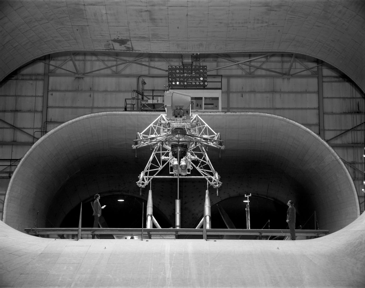
Concept model of the Lunar Excursion Module tested in the Full-Scale wind tunnel. -- Published in James R. Hansen, Spaceflight Revolution: NASA Langley Research Center From Sputnik to Apollo, (Washington: NASA, 1995), p. 356.-L69-670 Bell Lunar Landing Training Vehicle (LLTV): Following the crash of a sister Lunar Landing Training Vehicle at Ellington Field in Houston, Texas, the LLTV NASA 952 was sent from Houston to Langley for tests in the 30 x 60 Full Scale Tunnel. The LLTV was returned to Houston for further training use a short time later. NASA 952 is now on exhibit at the Johnson Space Center in Houston, Texas.
![Multiple exposure of Gemini rendezvous docking simulator. Francis B. Smith wrote in his paper "Simulators for Manned Space Research," "The rendezvous and docking operation of the Gemini spacecraft with the Agena and of the Apollo Command Module with the Lunar Excursion Module have been the subject of simulator studies for several years. [This figure] illustrates the Gemini-Agena rendezvous docking simulator at Langley. The Gemini spacecraft was supported in a gimbal system by an overhead crane and gantry arrangement which provided 6 degrees of freedom - roll, pitch, yaw, and translation in any direction - all controllable by the astronaut in the spacecraft. Here again the controls fed into a computer which in turn provided an input to the servos driving the spacecraft so that it responded to control motions in a manner which accurately simulated the Gemini spacecraft." A.W. Vogeley further described the simulator in his paper "Discussion of Existing and Planned Simulators For Space Research," "Docking operations are considered to start when the pilot first can discern vehicle target size and aspect and terminate, of course, when soft contact is made. ... This facility enables simulation of the docking operation from a distance of 200 feet to actual contact with the target. A full-scale mock-up of the target vehicle is suspended near one end of the track. ... On [the Agena target] we have mounted the actual Agena docking mechanism and also various types of visual aids. We have been able to devise visual aids which have made it possible to accomplish nighttime docking with as much success as daytime docking." -- Published in Barton C. Hacker and James M. Grimwood, On the Shoulders of Titans: A History of Project Gemini, NASA SP-4203; Francis B. Smith, "Simulators for Manned Space Research," Paper presented at the 1966 IEEE International convention, March 21-25, 1966; A.W. Vogeley, "Discussion of Existing and Planned Simulators For Space Research," Paper presented at the Conference on the Role of Simulation in Space Technology, August 17-21, 1964.](https://images-assets.nasa.gov/image/LRC-1963-B701_P-08973/LRC-1963-B701_P-08973~medium.jpg)
Multiple exposure of Gemini rendezvous docking simulator. Francis B. Smith wrote in his paper "Simulators for Manned Space Research," "The rendezvous and docking operation of the Gemini spacecraft with the Agena and of the Apollo Command Module with the Lunar Excursion Module have been the subject of simulator studies for several years. [This figure] illustrates the Gemini-Agena rendezvous docking simulator at Langley. The Gemini spacecraft was supported in a gimbal system by an overhead crane and gantry arrangement which provided 6 degrees of freedom - roll, pitch, yaw, and translation in any direction - all controllable by the astronaut in the spacecraft. Here again the controls fed into a computer which in turn provided an input to the servos driving the spacecraft so that it responded to control motions in a manner which accurately simulated the Gemini spacecraft." A.W. Vogeley further described the simulator in his paper "Discussion of Existing and Planned Simulators For Space Research," "Docking operations are considered to start when the pilot first can discern vehicle target size and aspect and terminate, of course, when soft contact is made. ... This facility enables simulation of the docking operation from a distance of 200 feet to actual contact with the target. A full-scale mock-up of the target vehicle is suspended near one end of the track. ... On [the Agena target] we have mounted the actual Agena docking mechanism and also various types of visual aids. We have been able to devise visual aids which have made it possible to accomplish nighttime docking with as much success as daytime docking." -- Published in Barton C. Hacker and James M. Grimwood, On the Shoulders of Titans: A History of Project Gemini, NASA SP-4203; Francis B. Smith, "Simulators for Manned Space Research," Paper presented at the 1966 IEEE International convention, March 21-25, 1966; A.W. Vogeley, "Discussion of Existing and Planned Simulators For Space Research," Paper presented at the Conference on the Role of Simulation in Space Technology, August 17-21, 1964.
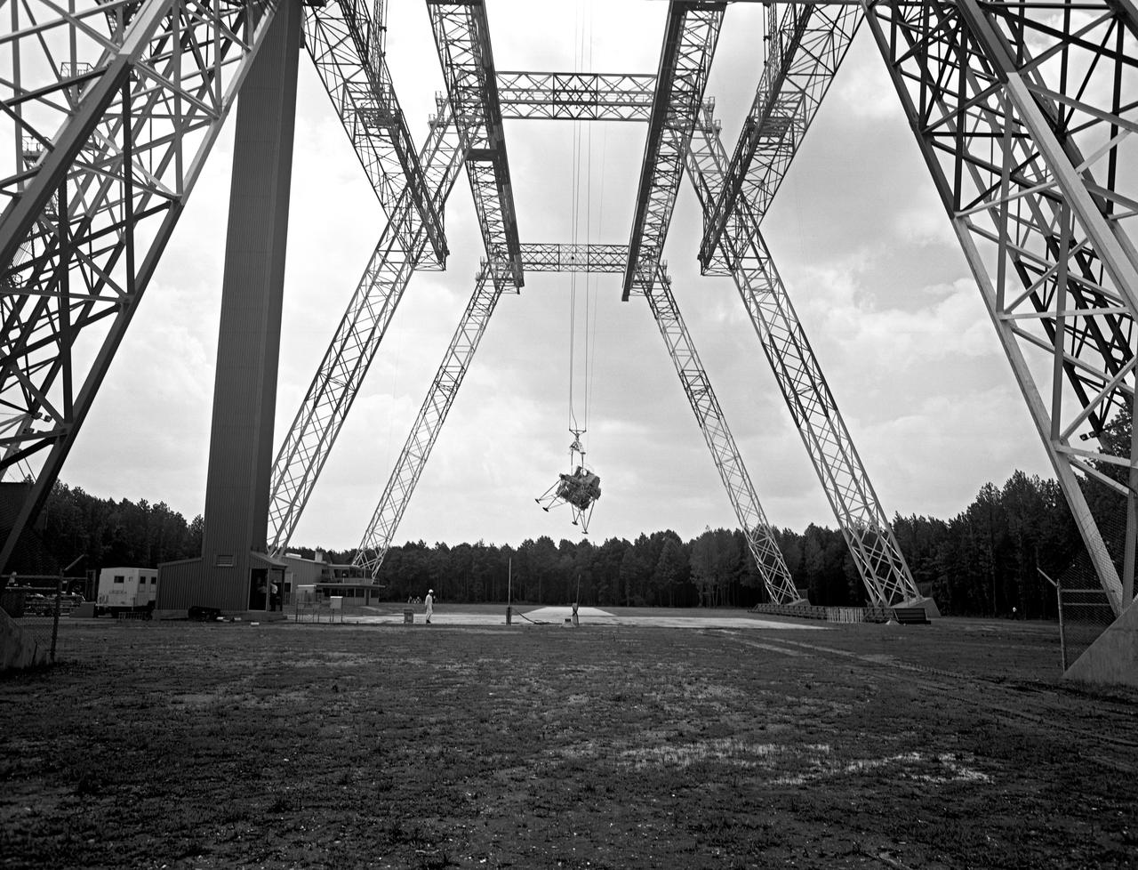
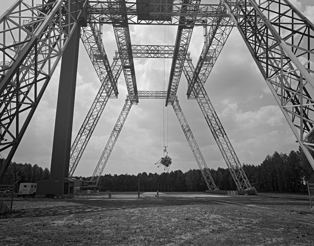
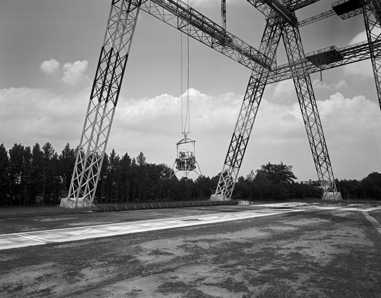
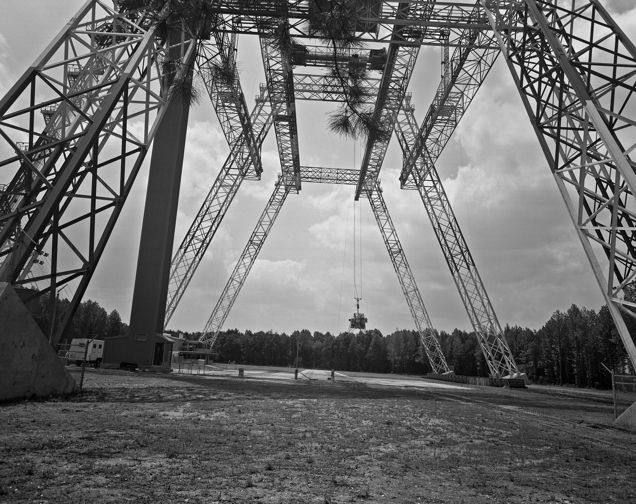
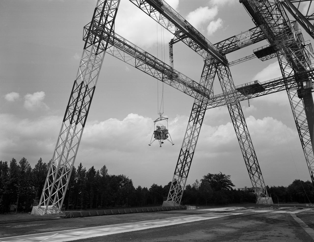
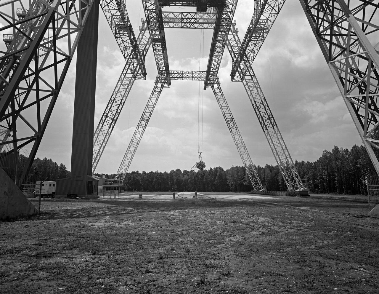
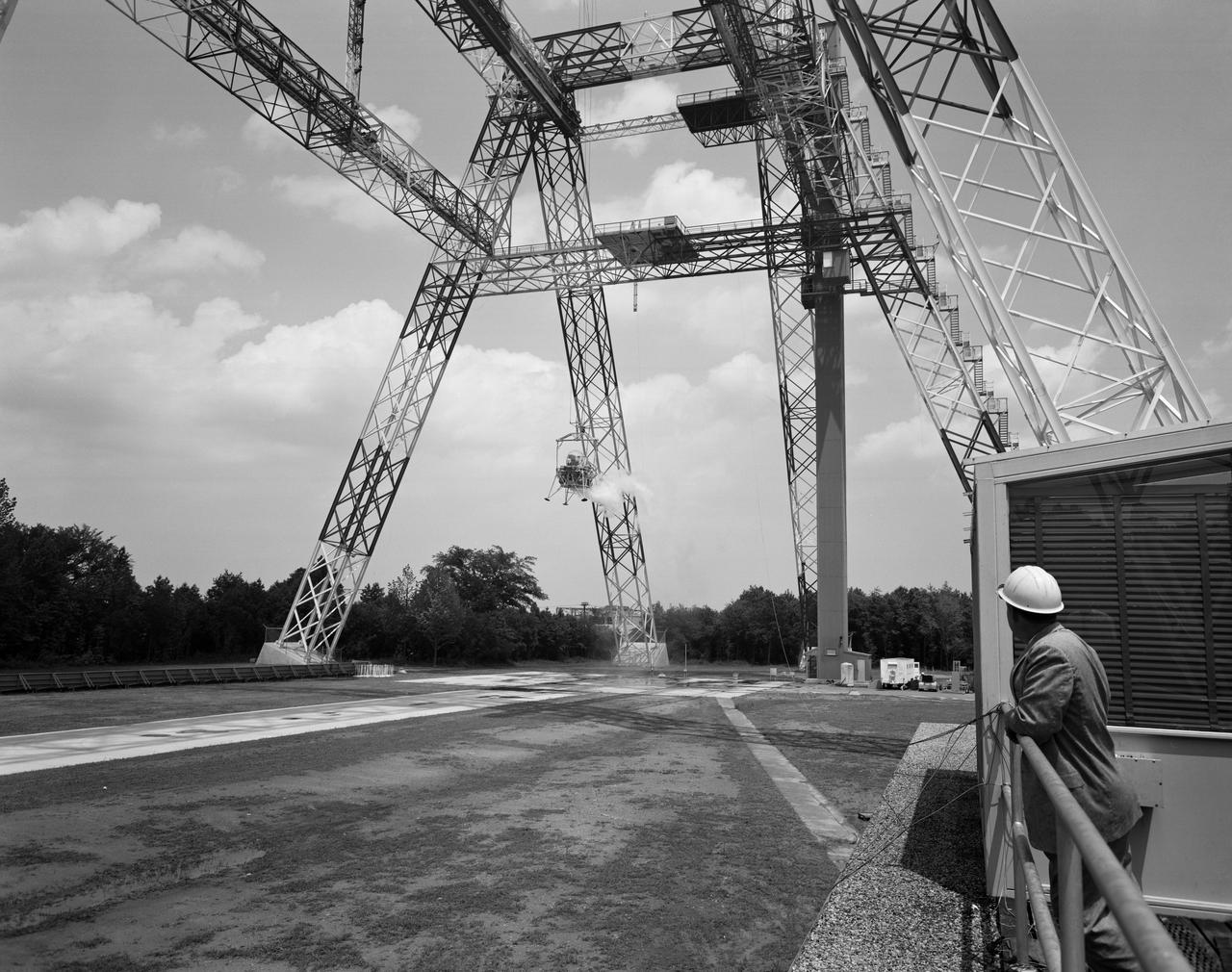
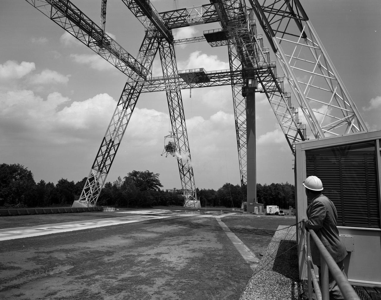
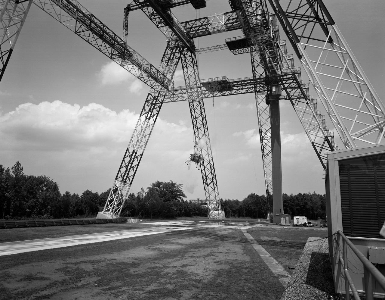
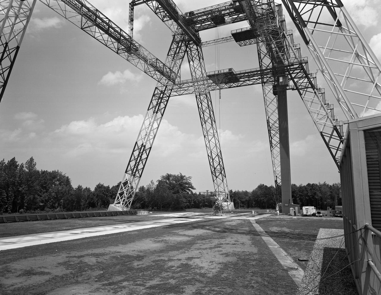
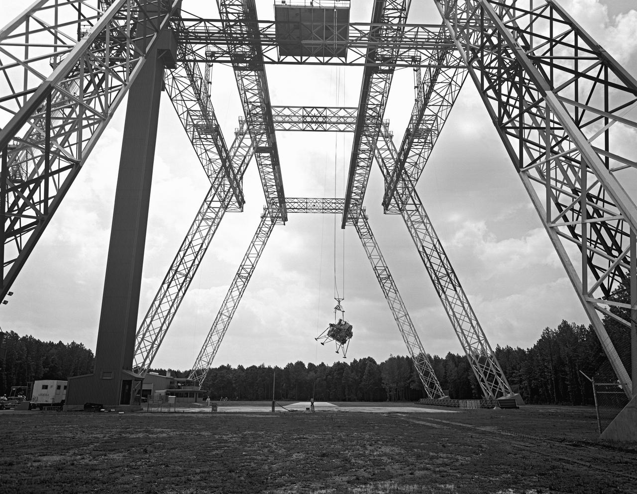
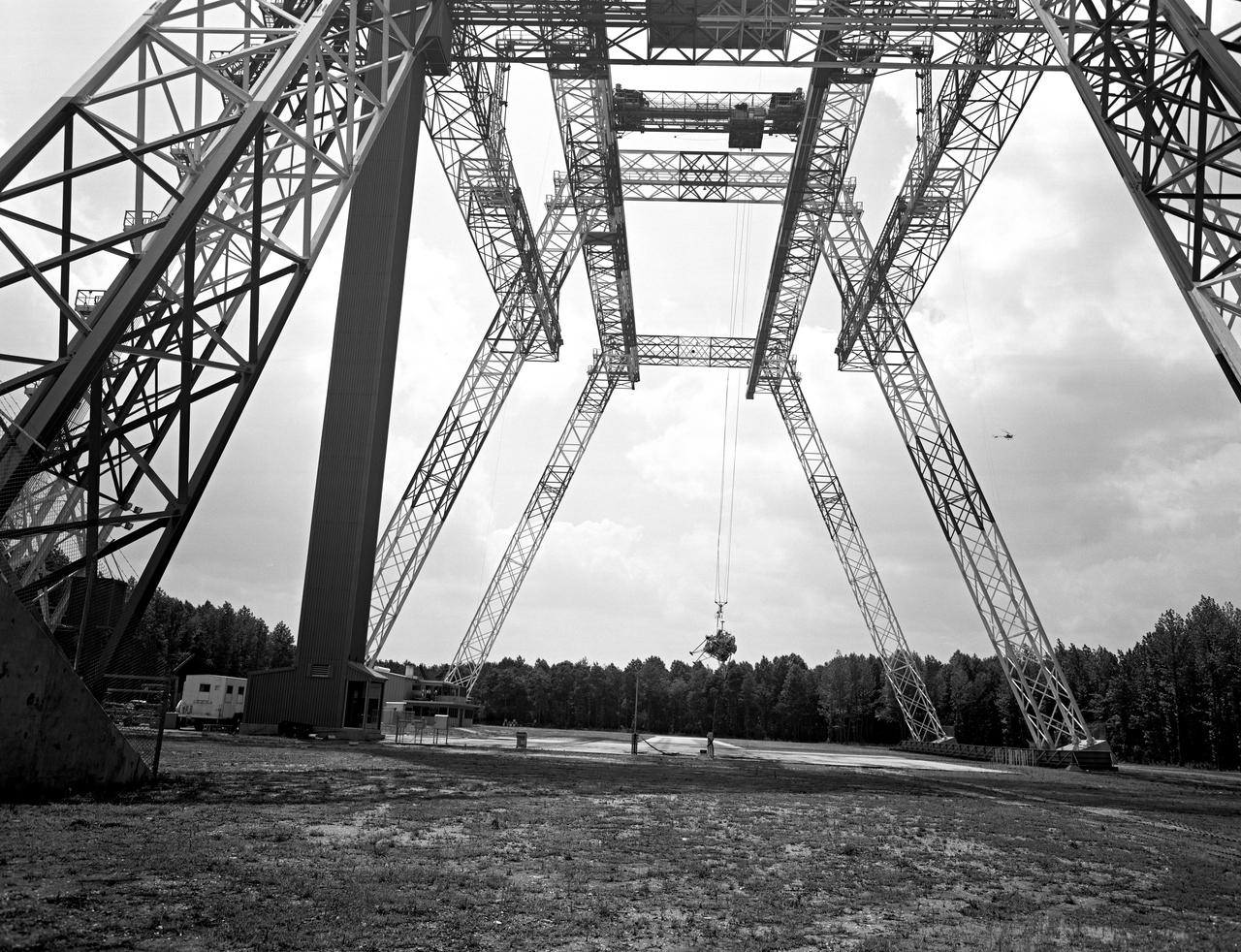
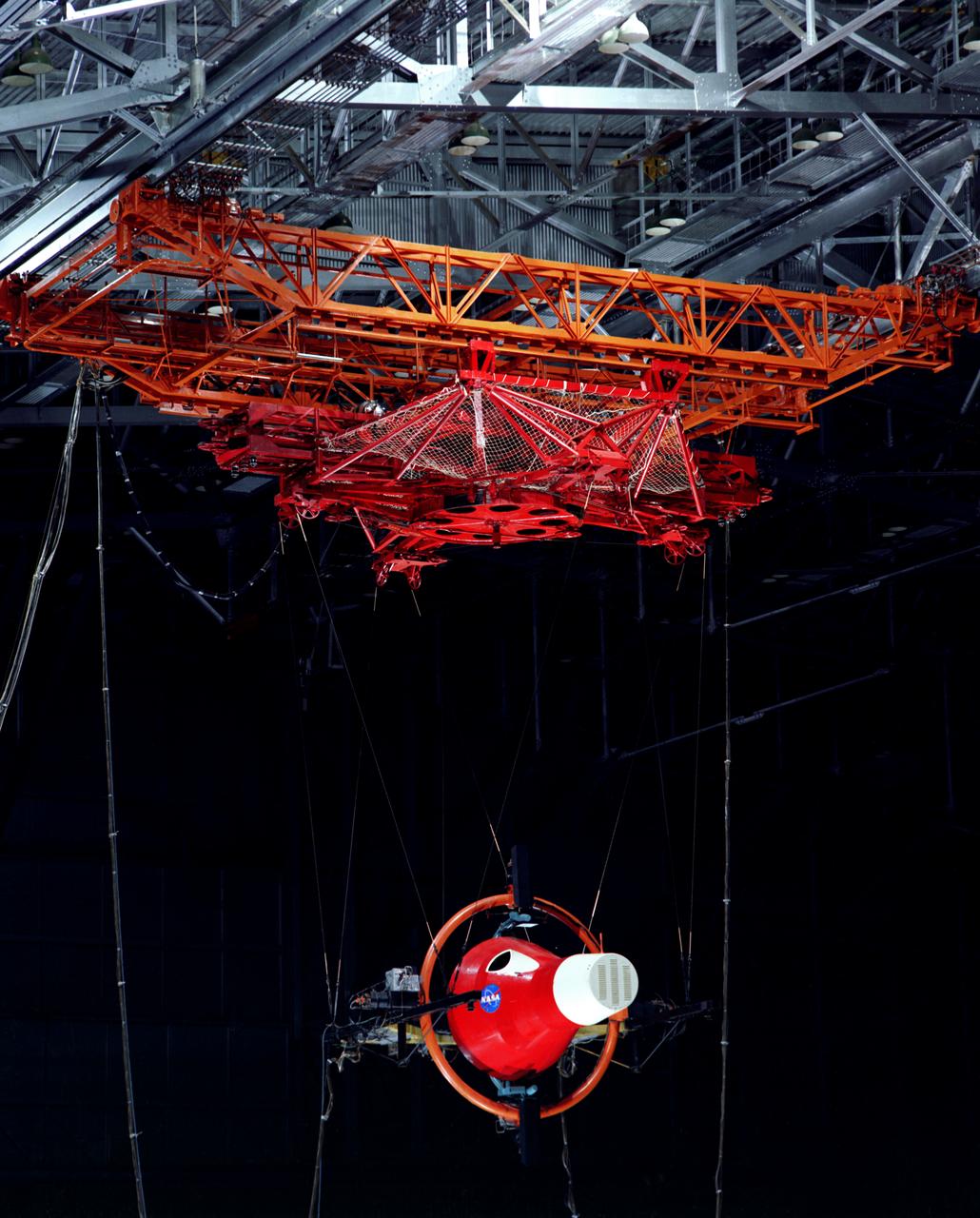
Lunar Landing Testing at NASA Langley. Lunar Landing Testing at NASA Langley. A simulated environment that contributed in a significant way to the success of Apollo project was the Lunar Landing Research Facility, an imposing 250 foot high, 400 foot long gantry structure that became operational in 1965. Published in the book "Space Flight Revolution" NASA SP-4308 pg. 376
Lunar Landing Testing at NASA Langley. Lunar Landing Testing at NASA Langley. A simulated environment that contributed in a significant way to the success of Apollo project was the Lunar Landing Research Facility, an imposing 250 foot high, 400 foot long gantry structure that became operational in 1965. Published in the book "Space Flight Revolution" NASA SP-4308 pg. 376
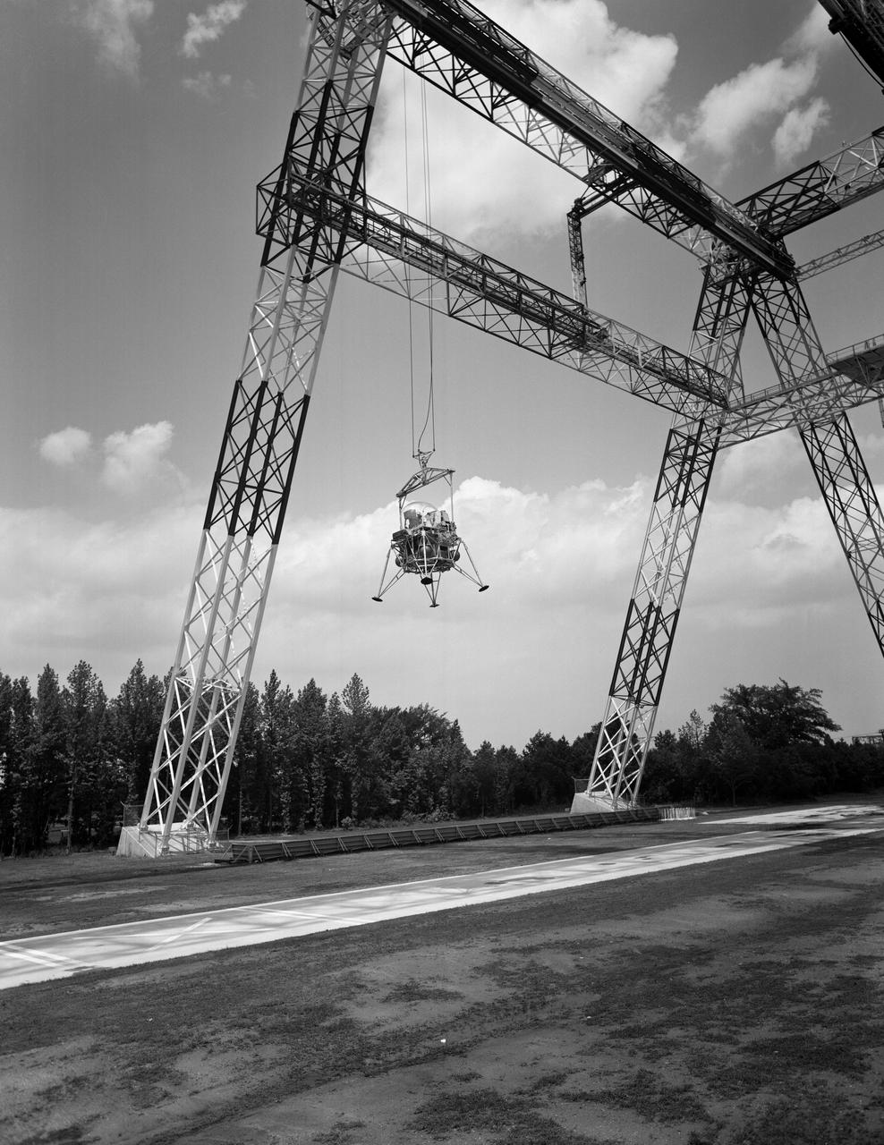
Lunar Landing Testing at NASA Langley. Lunar Landing Testing at NASA Langley. A simulated environment that contributed in a significant way to the success of Apollo project was the Lunar Landing Research Facility, an imposing 250 foot high, 400 foot long gantry structure that became operational in 1965. Published in the book "Space Flight Revolution" NASA SP-4308 pg. 376
Lunar Landing Testing at NASA Langley. Lunar Landing Testing at NASA Langley. A simulated environment that contributed in a significant way to the success of Apollo project was the Lunar Landing Research Facility, an imposing 250 foot high, 400 foot long gantry structure that became operational in 1965. Published in the book "Space Flight Revolution" NASA SP-4308 pg. 376
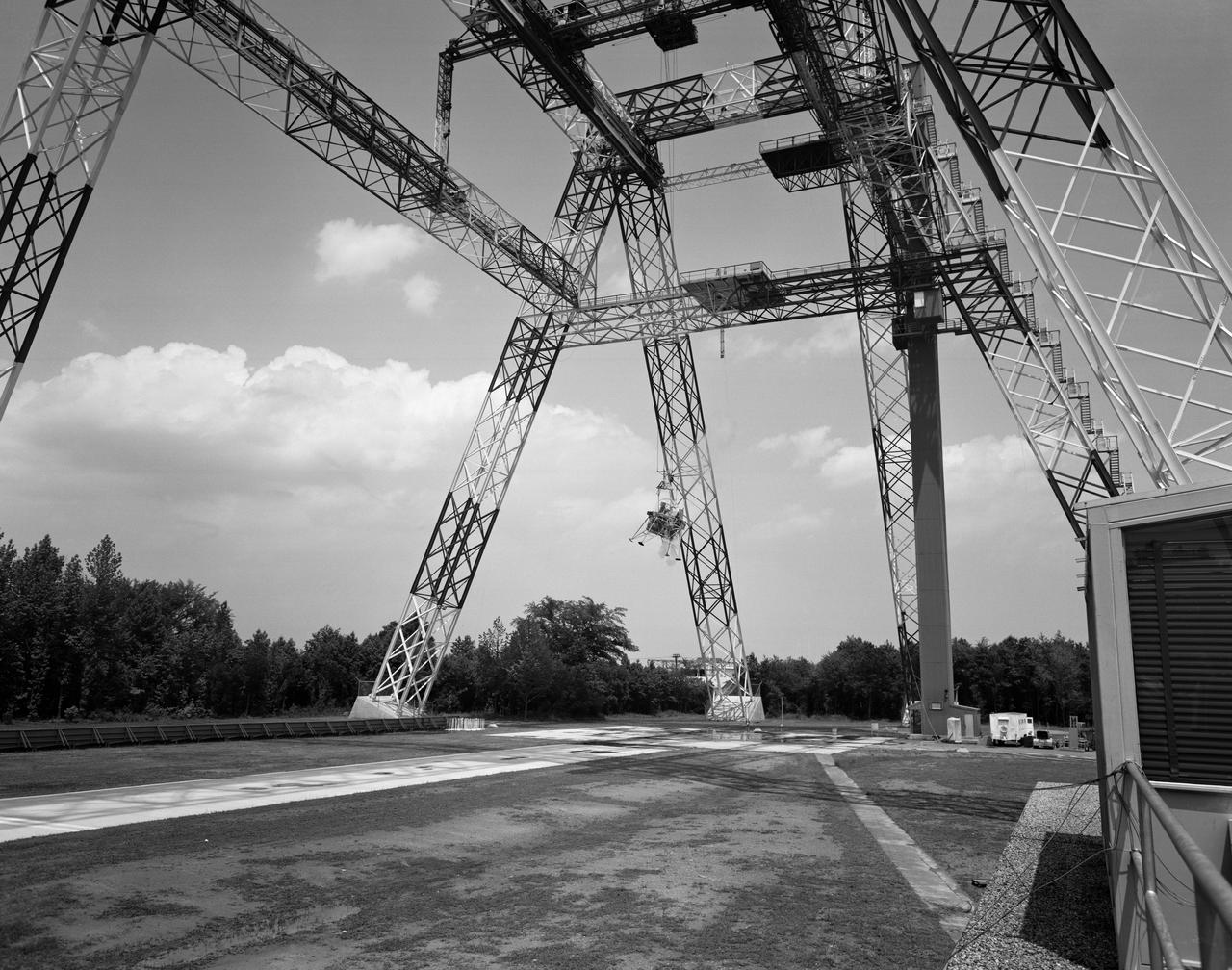
Lunar Landing Testing at NASA Langley. Lunar Landing Testing at NASA Langley. A simulated environment that contributed in a significant way to the success of Apollo project was the Lunar Landing Research Facility, an imposing 250 foot high, 400 foot long gantry structure that became operational in 1965. Published in the book "Space Flight Revolution" NASA SP-4308 pg. 376
Lunar Landing Testing at NASA Langley. Lunar Landing Testing at NASA Langley. A simulated environment that contributed in a significant way to the success of Apollo project was the Lunar Landing Research Facility, an imposing 250 foot high, 400 foot long gantry structure that became operational in 1965. Published in the book "Space Flight Revolution" NASA SP-4308 pg. 376
Lunar Landing Testing at NASA Langley. Lunar Landing Testing at NASA Langley. A simulated environment that contributed in a significant way to the success of Apollo project was the Lunar Landing Research Facility, an imposing 250 foot high, 400 foot long gantry structure that became operational in 1965. Published in the book "Space Flight Revolution" NASA SP-4308 pg. 376
Lunar Landing Testing at NASA Langley. Lunar Landing Testing at NASA Langley. A simulated environment that contributed in a significant way to the success of Apollo project was the Lunar Landing Research Facility, an imposing 250 foot high, 400 foot long gantry structure that became operational in 1965. Published in the book "Space Flight Revolution" NASA SP-4308 pg. 376
Lunar Landing Testing at NASA Langley. Lunar Landing Testing at NASA Langley. A simulated environment that contributed in a significant way to the success of Apollo project was the Lunar Landing Research Facility, an imposing 250 foot high, 400 foot long gantry structure that became operational in 1965. Published in the book "Space Flight Revolution" NASA SP-4308 pg. 376
Lunar Landing Testing at NASA Langley. Lunar Landing Testing at NASA Langley. A simulated environment that contributed in a significant way to the success of Apollo project was the Lunar Landing Research Facility, an imposing 250 foot high, 400 foot long gantry structure that became operational in 1965. Published in the book "Space Flight Revolution" NASA SP-4308 pg. 376
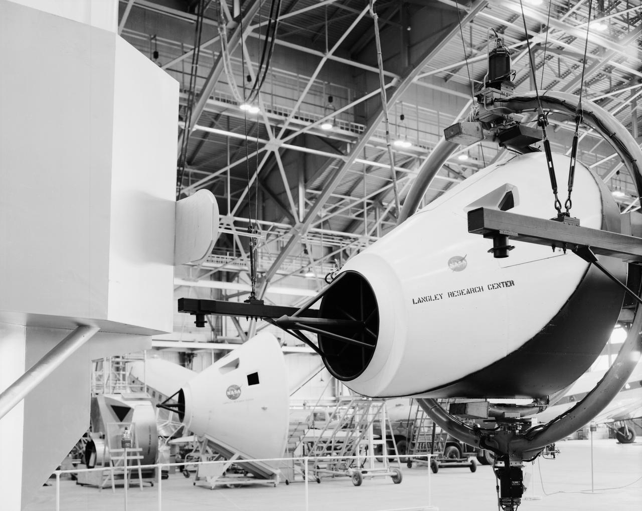
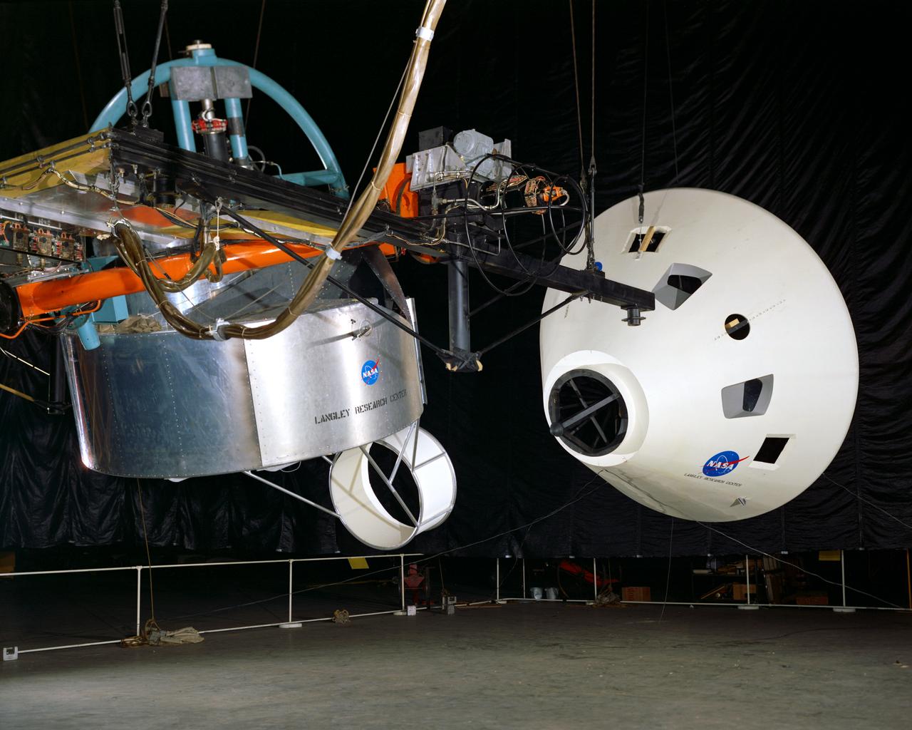
Originally the Rendezvous was used by the astronauts preparing for Gemini missions. The Rendezvous Docking Simulator was then modified and used to develop docking techniques for the Apollo program. This picture shows a later configuration of the Apollo docking with the LEM target. A.W. Vogeley described the simulator as follows: The Rendezvous Docking Simulator and also the Lunar Landing Research Facility are both rather large moving-base simulators. It should be noted, however, that neither was built primarily because of its motion characteristics. The main reason they were built was to provide a realistic visual scene. A secondary reason was that they would provide correct angular motion cues (important in control of vehicle short-period motions) even though the linear acceleration cues would be incorrect. -- Published in A.W. Vogeley, Piloted Space-Flight Simulation at Langley Research Center, Paper presented at the American Society of Mechanical Engineers, 1966 Winter Meeting, New York, NY, November 27 - December 1, 1966.
Lunar Landing Testing at NASA Langley. Lunar Landing Testing at NASA Langley. A simulated environment that contributed in a significant way to the success of Apollo project was the Lunar Landing Research Facility, an imposing 250 foot high, 400 foot long gantry structure that became operational in 1965. Published in the book "Space Flight Revolution" NASA SP-4308 pg. 376
Lunar Landing Testing at NASA Langley. Lunar Landing Testing at NASA Langley. A simulated environment that contributed in a significant way to the success of Apollo project was the Lunar Landing Research Facility, an imposing 250 foot high, 400 foot long gantry structure that became operational in 1965. Published in the book "Space Flight Revolution" NASA SP-4308 pg. 376
Lunar Landing Testing at NASA Langley. Lunar Landing Testing at NASA Langley. A simulated environment that contributed in a significant way to the success of Apollo project was the Lunar Landing Research Facility, an imposing 250 foot high, 400 foot long gantry structure that became operational in 1965. Published in the book "Space Flight Revolution" NASA SP-4308 pg. 376
Lunar Landing Testing at NASA Langley. Lunar Landing Testing at NASA Langley. A simulated environment that contributed in a significant way to the success of Apollo project was the Lunar Landing Research Facility, an imposing 250 foot high, 400 foot long gantry structure that became operational in 1965. Published in the book "Space Flight Revolution" NASA SP-4308 pg. 376
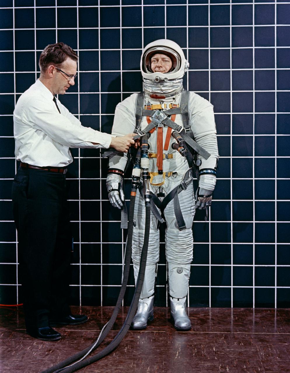
Engineer Bill Peterson fits test pilot Bob Smyth in spacesuit A-3H-024 with the LEM Astronaut restraint harness during suit evaluation study.
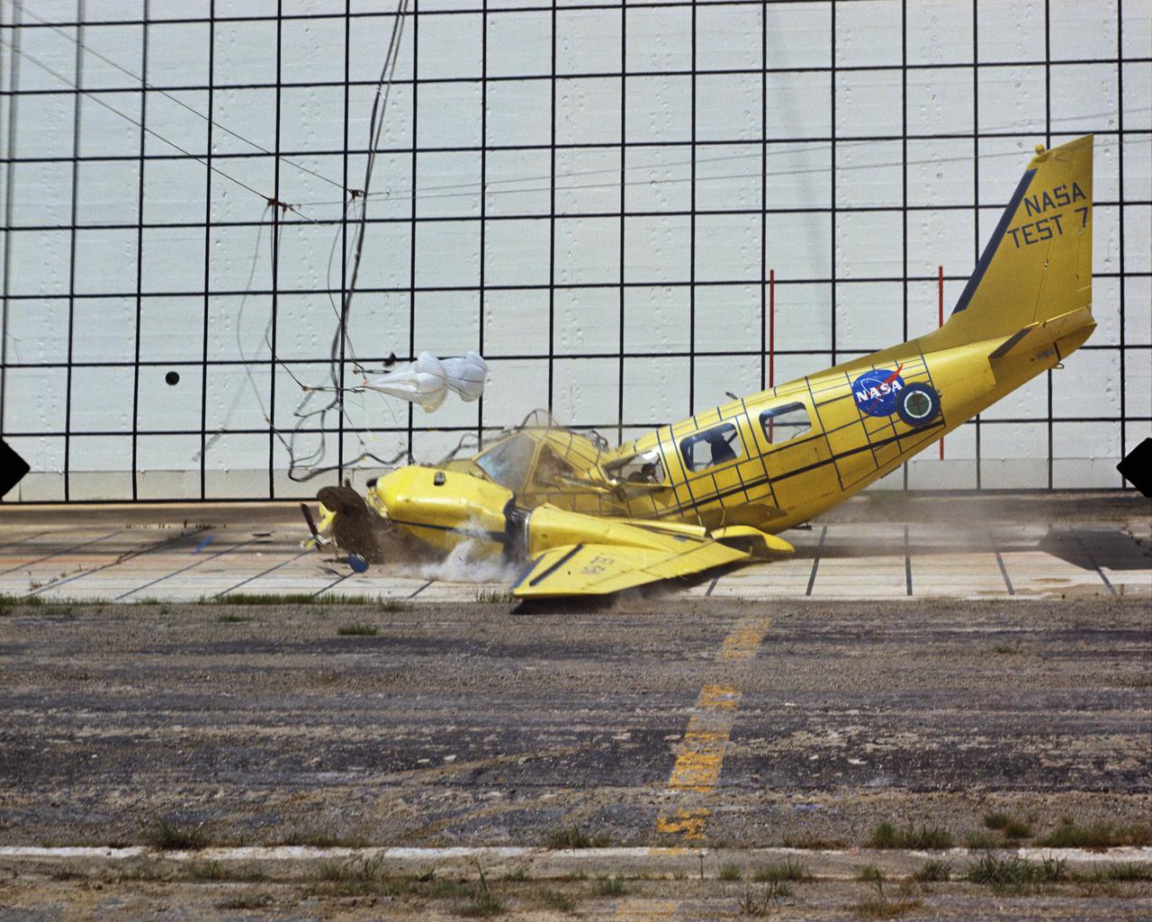
Photographed on: 08/03/75. -- By 1972 the Lunar Landing Research Facility was no longer in use for its original purpose. The 400-foot high structure was swiftly modified to allow engineers to study the dynamics of aircraft crashes. "The Impact Dynamics Research Facility is used to conduct crash testing of full-scale aircraft under controlled conditions. The aircraft are swung by cables from an A-frame structure that is approximately 400 ft. long and 230 foot high. The impact runway can be modified to simulate other grand crash environments, such as packed dirt, to meet a specific test requirement." "In 1972, NASA and the FAA embarked on a cooperative effort to develop technology for improved crashworthiness and passenger survivability in general aviation aircraft with little or no increase in weight and acceptable cost. Since then, NASA has "crashed" dozens of GA aircraft by using the lunar excursion module (LEM) facility originally built for the Apollo program." This photograph shows Crash Test No. 7. Crash Test: Test #7
Multiple exposure of Rendezvous Docking Simulator. Francis B. Smith, described the simulator as follows: The rendezvous and docking operation of the Gemini spacecraft with the Agena and of the Apollo Command Module with the Lunar Excursion Module have been the subject of simulator studies for several years. This figure illustrates the Gemini-Agena rendezvous docking simulator at Langley. The Gemini spacecraft was supported in a gimbal system by an overhead crane and gantry arrangement which provided 6 degrees of freedom - roll, pitch, yaw, and translation in any direction - all controllable by the astronaut in the spacecraft. Here again the controls fed into a computer which in turn provided an input to the servos driving the spacecraft so that it responded to control motions in a manner which accurately simulated the Gemini spacecraft. -- Published in Barton C. Hacker and James M. Grimwood, On the Shoulders of Titans: A History of Project Gemini, NASA SP-4203 Francis B. Smith, Simulators for Manned Space Research, Paper presented at the 1966 IEEE International convention, March 21-25, 1966.
Gemini Rendezvous Docking Simulator suspended from the roof of the Langley Research Center s aircraft hangar. Francis B. Smith wrote: The rendezvous and docking operation of the Gemini spacecraft with the Agena and of the Apollo Command Module with the Lunar Excursion Module have been the subject of simulator studies for several years. This figure illustrates the Gemini-Agena rendezvous docking simulator at Langley. The Gemini spacecraft was supported in a gimbal system by an overhead crane and gantry arrangement which provided 6 degrees of freedom - roll, pitch, yaw, and translation in any direction - all controllable by the astronaut in the spacecraft. Here again the controls fed into a computer which in turn provided an input to the servos driving the spacecraft so that it responded to control motions in a manner which accurately simulated the Gemini spacecraft. -- Published in Barton C. Hacker and James M. Grimwood, On the Shoulders of Titans: A History of Project Gemini, NASA SP-4203 Francis B. Smith, Simulators for Manned Space Research, Paper presented at the 1966 IEEE International convention, March 21-25, 1966.
Multiple exposure of Rendezvous Docking Simulator. Francis B. Smith, described the simulator as follows: The rendezvous and docking operation of the Gemini spacecraft with the Agena and of the Apollo Command Module with the Lunar Excursion Module have been the subject of simulator studies for several years. This figure illustrates the Gemini-Agena rendezvous docking simulator at Langley. The Gemini spacecraft was supported in a gimbal system by an overhead crane and gantry arrangement which provided 6 degrees of freedom - roll, pitch, yaw, and translation in any direction - all controllable by the astronaut in the spacecraft. Here again the controls fed into a computer which in turn provided an input to the servos driving the spacecraft so that it responded to control motions in a manner which accurately simulated the Gemini spacecraft. -- Published in Barton C. Hacker and James M. Grimwood, On the Shoulders of Titans: A History of Project Gemini, NASA SP-4203 Francis B. Smith, Simulators for Manned Space Research, Paper presented at the 1966 IEEE International convention, March 21-25, 1966.
Lunar Landing Testing at NASA Langley. Lunar Landing Testing at NASA Langley. A simulated environment that contributed in a significant way to the success of Apollo project was the Lunar Landing Research Facility, an imposing 250 foot high, 400 foot long gantry structure that became operational in 1965. Published in the book "Space Flight Revolution" NASA SP-4308 pg. 376
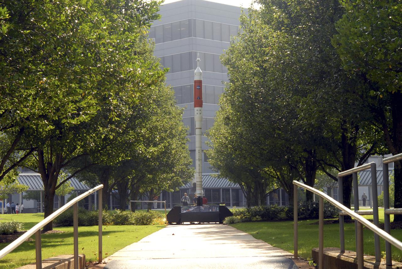
A model of the new Aries I crew launch vehicle, for which NASA is designing, testing and evaluating hardware and related systems, is seen here on display at the Marshall Space Fight Center (MSFC), in Huntsville, Alabama. The Ares I crew launch vehicle is the rocket that will carry a new generation of space explorers into orbit. Under the goals of the Vision for Space Exploration, Ares I is a chief component of the cost-effective space transportation infrastructure being developed by NASA’s Constellation Program. These transportation systems will safely and reliably carry human explorers back to the moon, and then onward to Mars and other destinations in the solar system. The Ares I effort includes multiple project element teams at NASA centers and contract organizations around the nation, and is led by the Exploration Launch Projects Office at NASA’s MFSC. Together, these teams are developing vehicle hardware, evolving proven technologies, and testing components and systems. Their work builds on powerful, reliable space shuttle propulsion elements and nearly a half-century of NASA space flight experience and technological advances. Ares I is an inline, two-stage rocket configuration topped by the Crew Exploration Vehicle, its service module and a launch abort system. The launch vehicle’s first stage is a single, five-segment reusable solid rocket booster derived from the Space Shuttle Program’s reusable solid rocket motor that burns a specially formulated and shaped solid propellant called polybutadiene acrylonitrile (PBAN). The second or upper stage will be propelled by a J-2X main engine fueled with liquid oxygen and liquid hydrogen. In addition to its primary mission of carrying crews of four to six astronauts to Earth orbit, the launch vehicle’s 25-ton payload capacity might be used for delivering cargo to space, bringing resources and supplies to the International Space Station or dropping payloads off in orbit for retrieval and transport to exploration teams on the moon. Crew transportation to the space station is planned to begin no later than 2014. The first lunar excursion is scheduled for the 2020 timeframe.