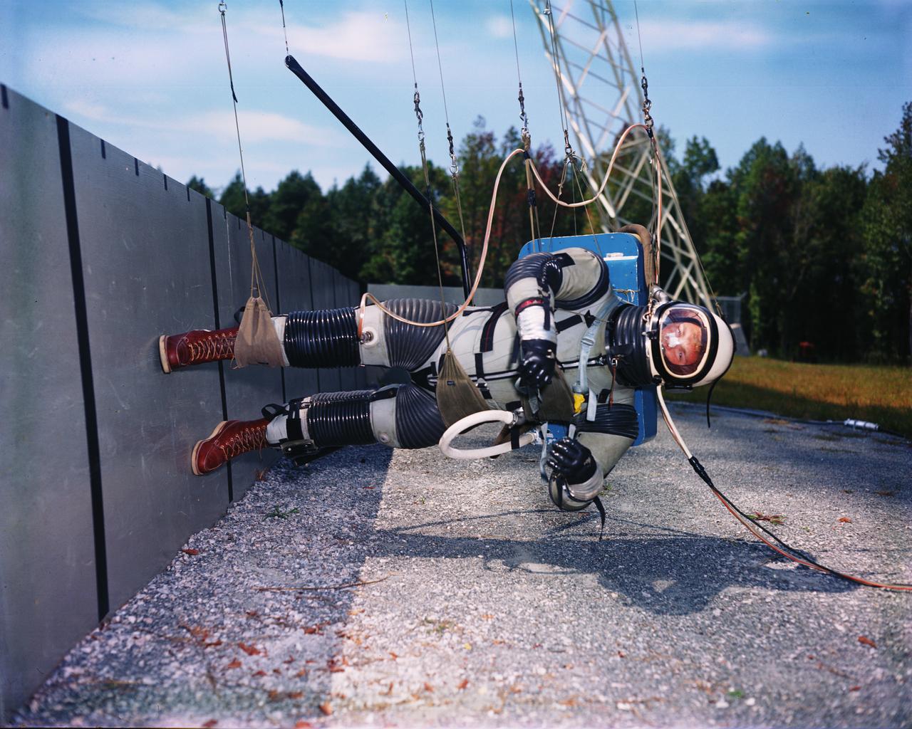
Lunar Landing Walking Simulator: Researchers at Langley study the ability of astronauts to walk, run and perform other tasks required during lunar exploration. The Reduced Gravity Simulator gave researchers the opportunity to look at the effects of one-sixth normal gravity on self-locomotion. Several Apollo astronauts practiced lunar waling at the facility.
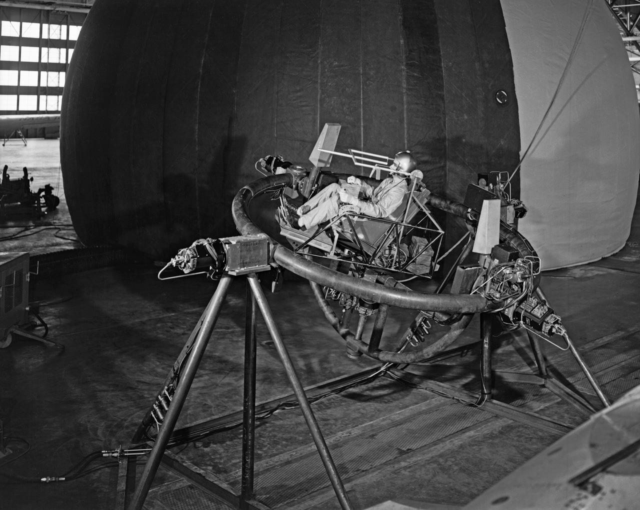
Lunar Take Off Simulator: This simulator is used by scientists at the Langley Research Center ... to help determine human ability to control a lunar launch vehicle in vertical alignment during takeoff from the moon for rendezvous with a lunar satellite vehicle on the return trip to earth. The three-axis chair, a concept which allows the pilot to sit upright during launch, gives the navigator angular motion (pitch, role, and yaw) cues as he operates the vehicle through a sidearm control system. The sight apparatus in front of the pilot's face enables him to align the vehicle on a course toward a chosen star, which will be followed as a guidance reference during the lunar launch. The pilot's right hand controls angular motions, while his left hand manipulates the thrust lever. The simulator is designed for operation inside an artificial planetarium, where a star field will be projected against the ceiling during "flights". The tests are part of an extensive NASA program at Langley in the study of problems relating to a manned lunar mission. (From a NASA Langley, photo release caption.)
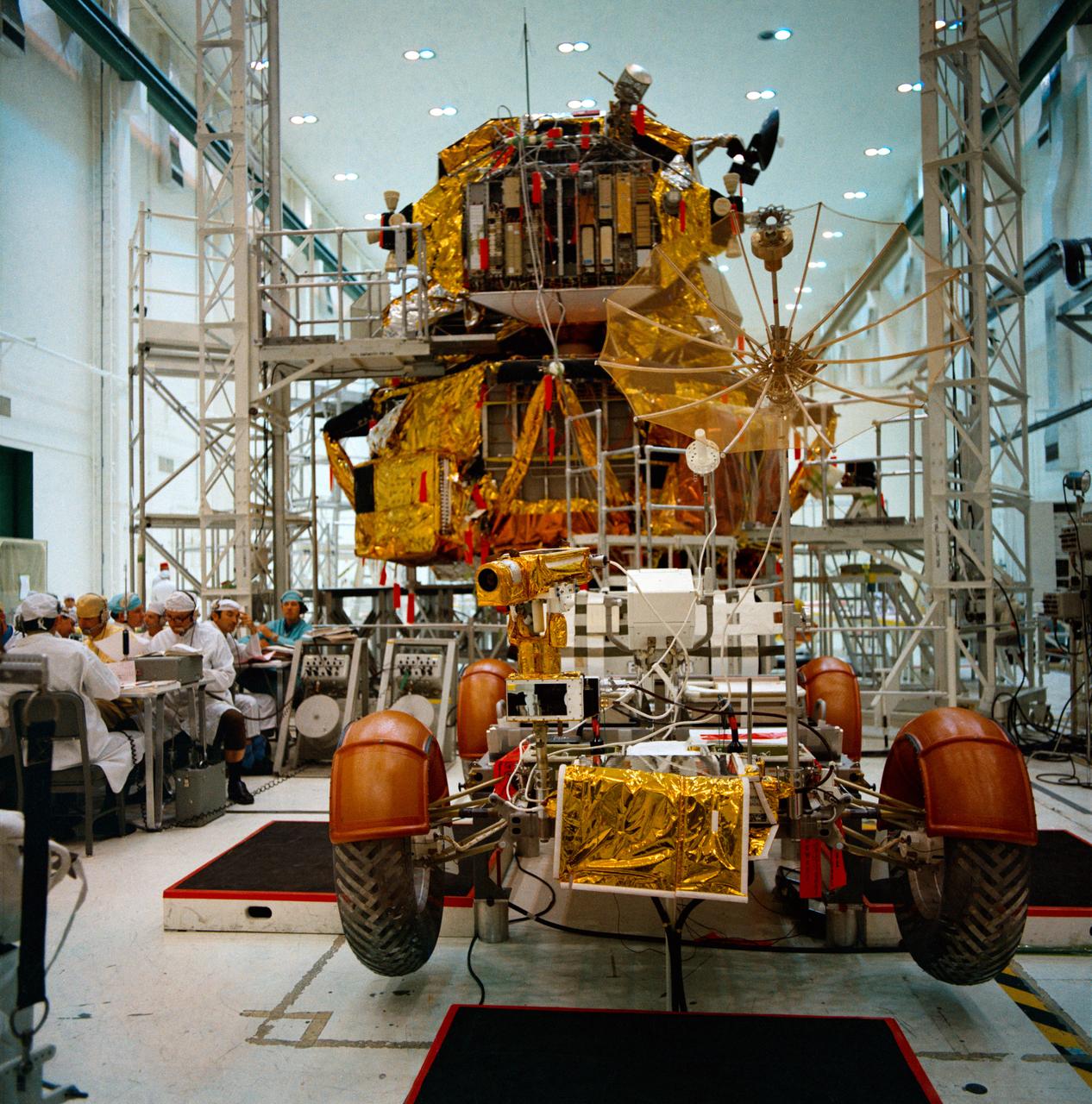
S71-30542 (21 April 1971) --- An overall view of the Apollo 15 Lunar Roving Vehicle (LRV) and the Lunar Module (LM) during simulations at the Kennedy Space Center (KSC). Astronauts David R. Scott, commander, and James B. Irwin, lunar module pilot, will man the LRV on the lunar surface during their August 1971 traverses. Rover 1 will permit the astronauts to cover a larger area of the moon for exploration and sample collecting than on previous missions.
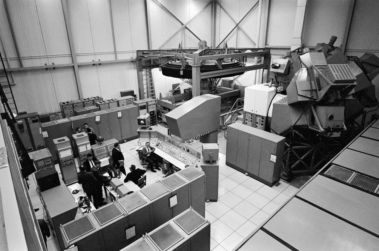
Overall view of the Lunar Module Mission Simulator, an astronaut training facility located in bldg 5.
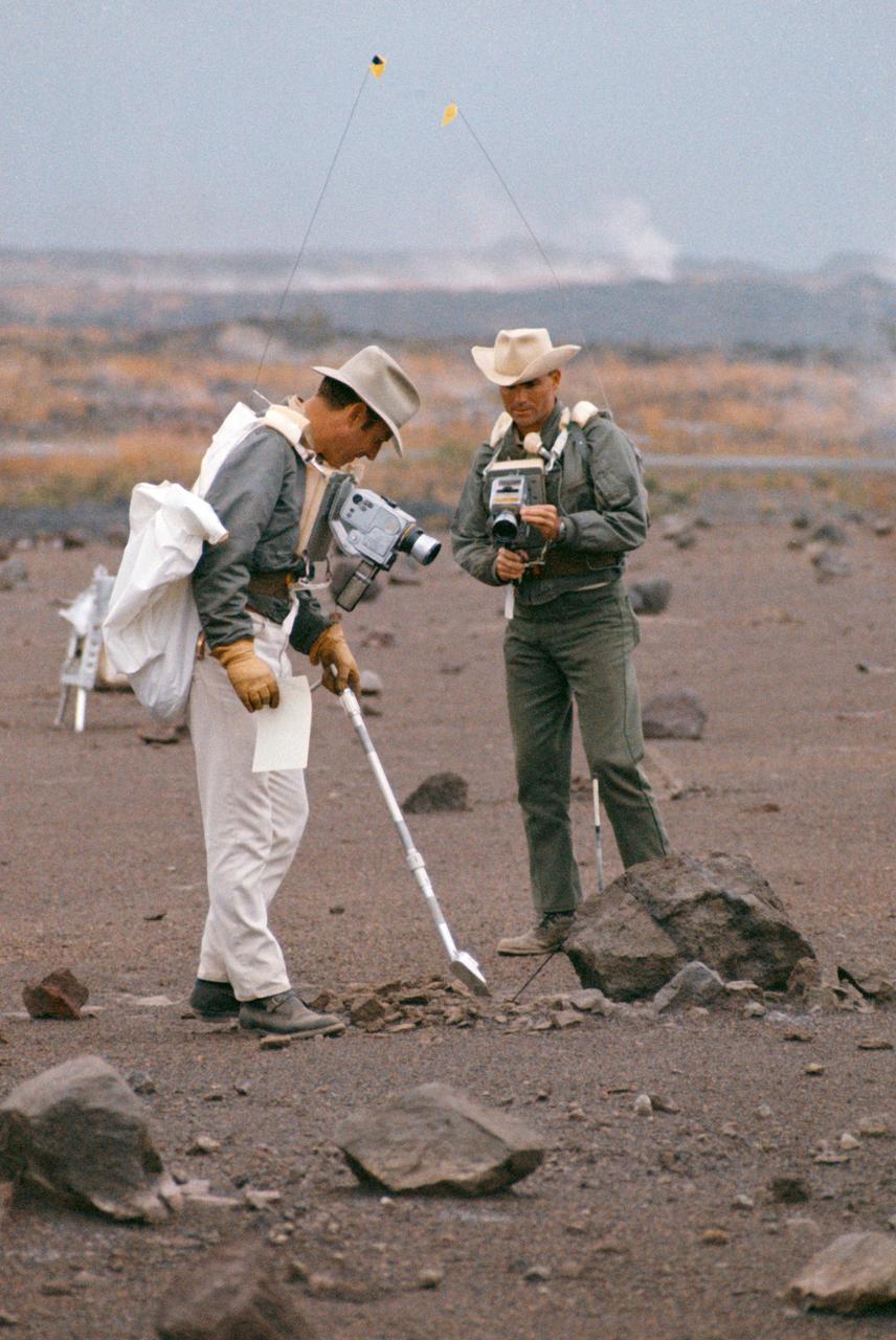
S70-20253 (December 1969) --- Astronauts James A. Lovell Jr. (left) commander, and Fred W. Haise Jr., lunar module pilot, carry out a simulation of a lunar traverse at Kilauea, Hawaii, site. Both crew members of NASA's third team of moon explorers were carrying cameras and communications equipment during the simulated traverse. They maintained contact with men in the roles of spacecraft throughout the traverse. Lovell holds a scoop for the Apollo Lunar Hand Tools (ALHT) and a gnomon, also for the ALHT is deployed in front of Haise. The ALHT carrier is at left background, (almost obscured by Lovell).
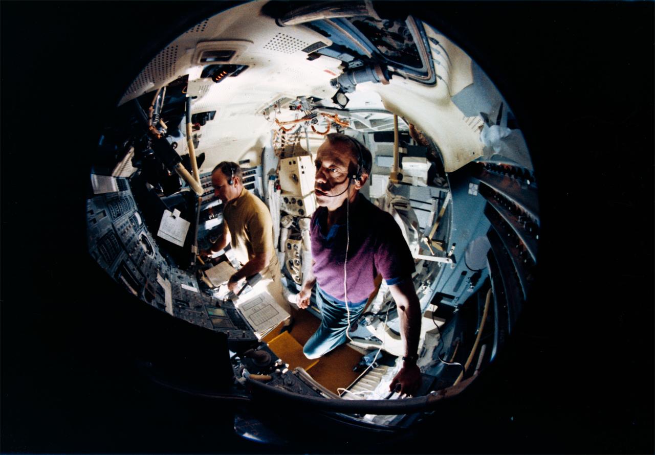
S70-45555 (July 1970) --- A fish-eye lens view showing astronauts Alan B. Shepard Jr. (foreground) and Edgar D. Mitchell in the Apollo lunar module mission simulator at the Kennedy Space Center during preflight training for the Apollo 14 lunar landing mission. Shepard is the Apollo 14 commander; and Mitchell is the lunar module pilot.
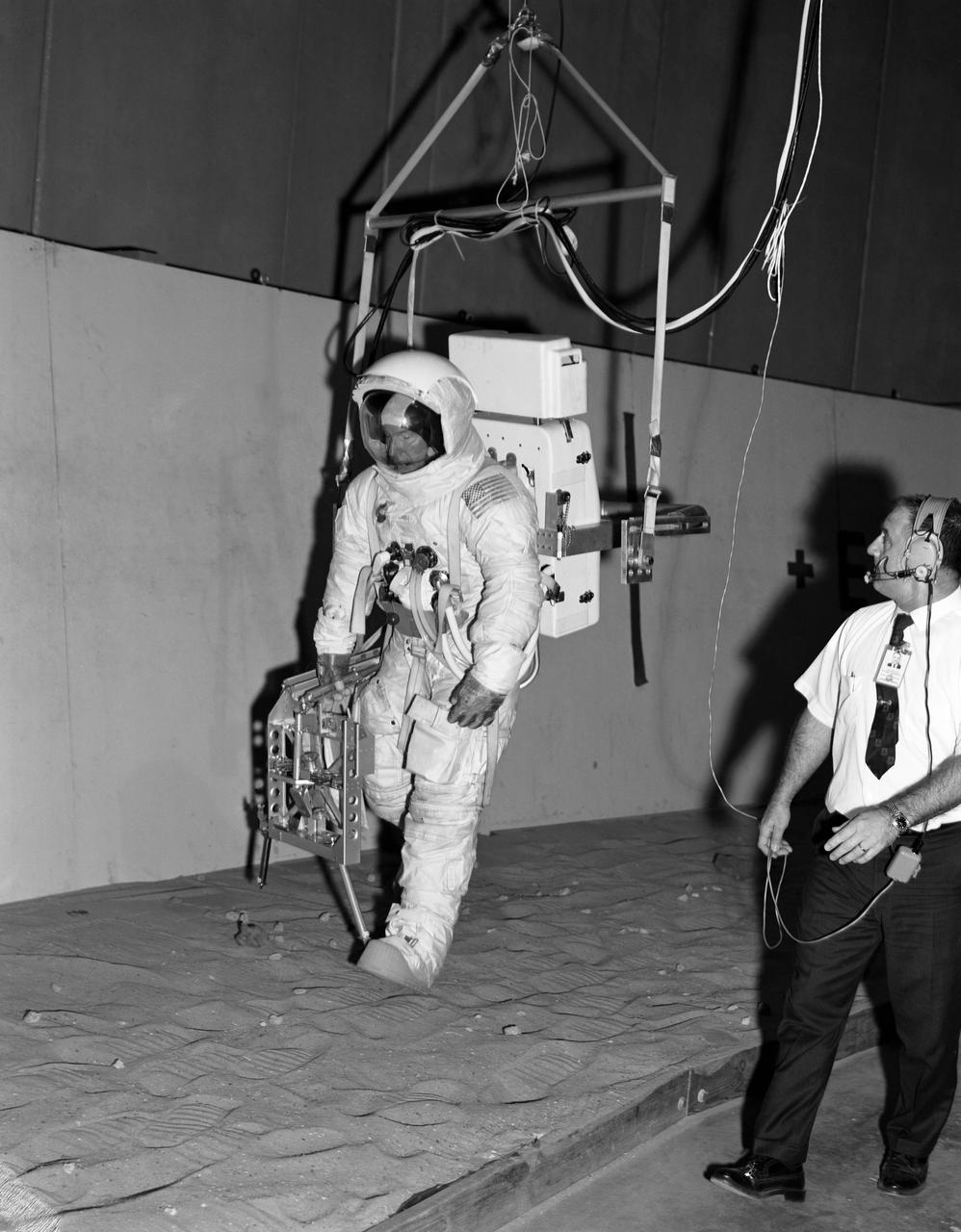
S70-28229 (16 Jan. 1970) --- Astronaut James A. Lovell Jr., commander of the Apollo 13 lunar landing mission, participates in lunar surface simulation training at the Manned Spacecraft Center. Lovell is attached to a Six Degrees of Freedom Simulator. He is carrying an Apollo Lunar Hand Tools carrier in his right hand.
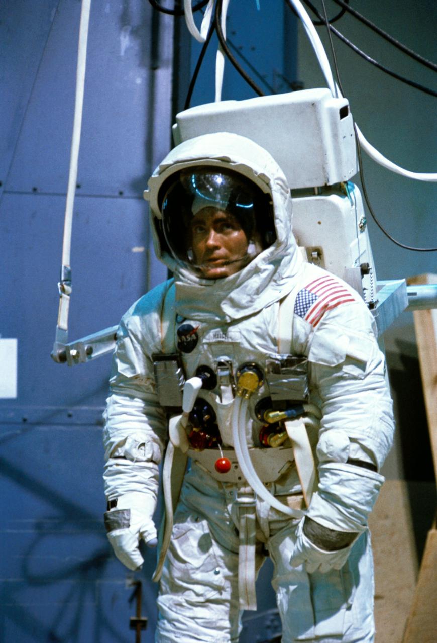
S70-24012 (19 Jan. 1970) --- Astronaut Fred W. Haise Jr., lunar module pilot of the Apollo 13 lunar landing mission, participates in lunar surface simulation training at the Manned Spacecraft Center (MSC). Haise is attached to a Six Degrees of Freedom Simulator.

Astronaut John W. Young, Apollo 16 prime crew commander (right), takes a drive in the One-G Lunar Roving Vehicle (LRV) trainer in the Lunar Topgraphic Simulation area at the Manned Spacecraft Center (MSC). He is accompanied by John Omstead, with General Electric, MSC.
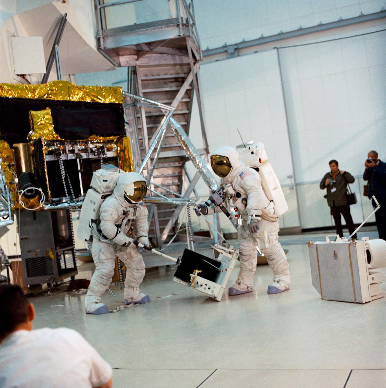
S70-27036 (4 Feb. 1970) --- Two crew men of the Apollo 13 lunar landing mission simulate lunar surface extravehicular activity (EVA) during training exercises in the Kennedy Space Center's (KSC) Flight Crew Training Building. They are astronauts James A. Lovell Jr. commander; and Fred W. Haise Jr., lunar module pilot.
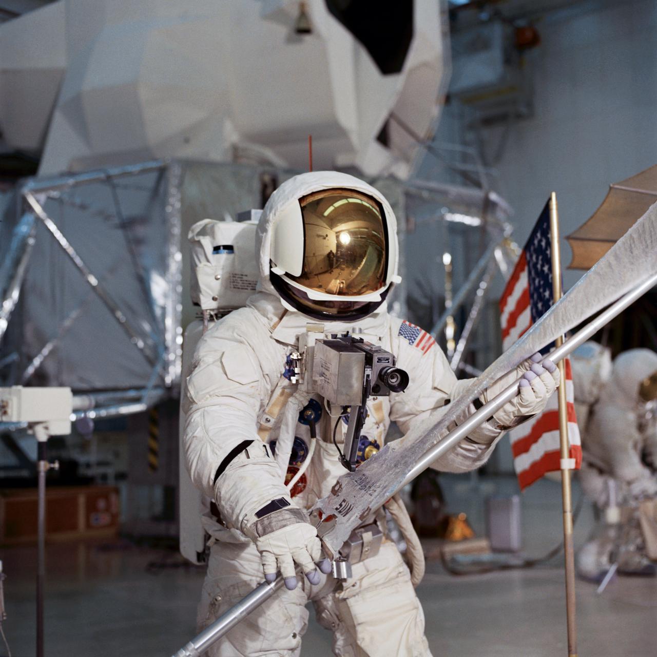
S70-27034 (4 Feb. 1970) --- Astronaut Fred W. Haise Jr., lunar module pilot of the Apollo 13 lunar landing mission, simulates lunar surface extravehicular activity (EVA) during training exercises in the Kennedy Space Center's (KSC) Flight Crew Training Building (FCTB). Haise, wearing an Extravehicular Mobility Unit (EMU), is holding a Solar Wind Composition (SWC) experiment.
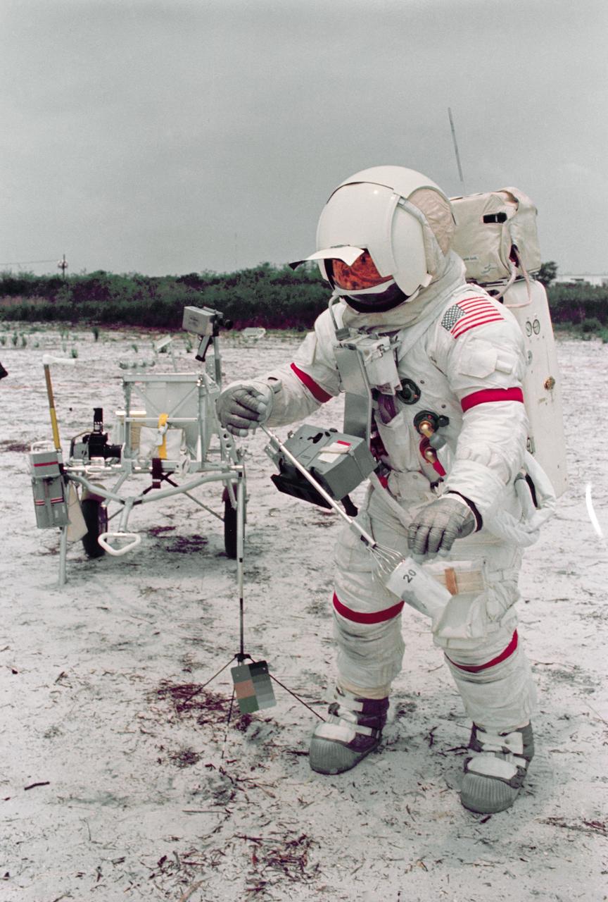
S70-46157 (July 1970) --- Astronaut Alan B. Shepard Jr., commander of the Apollo 14 lunar landing mission, participates in lunar surface simulation training at the Kennedy Space Center (KSC). The modular equipment transporter (MET) is in the left background, in the center foreground is a gnomon. The MET, nicknamed the "Rickshaw", will serve as a portable work bench with a place for the Apollo lunar hand tools and their carrier, three cameras, two sample container bags, a special environment sample container, spare magazines, and a lunar surface Penetrometer. Shepard is wearing an Extravehicular Mobility Unit (EMU).
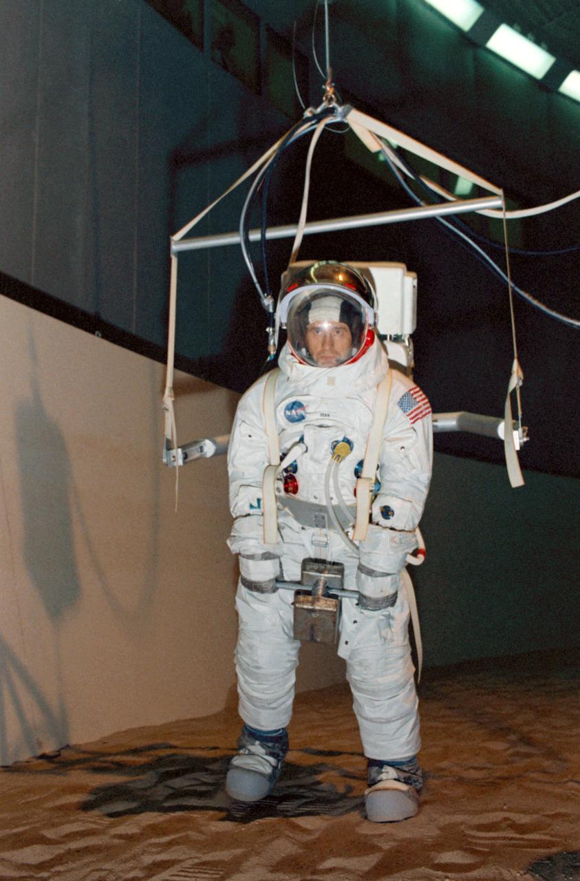
S69-56059 (24 Oct. 1969) --- Astronaut Alan L. Bean, lunar module pilot of the Apollo 12 lunar landing mission, participates in lunar surface simulation training in Building 29 at the Manned Spacecraft Center (MSC). Bean is strapped to a one-sixth gravity simulator.
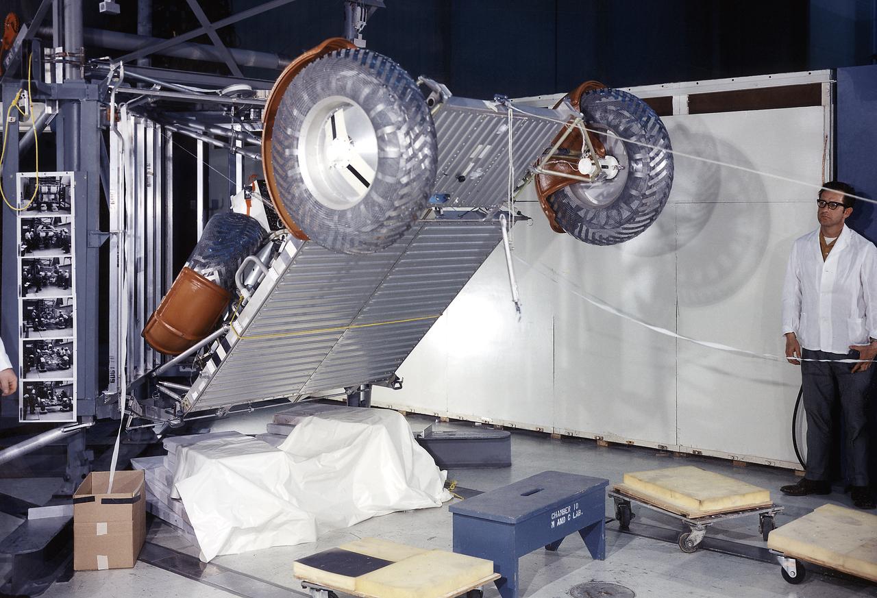
This photograph was taken during a deployment simulation of the Lunar Roving Vehicle (LRV). The LRV was built to give Apollo astronauts a greater range of mobility during the last three lunar exploration missions; Apollo 15, Apollo 16, and Apollo 17. It was designed and developed by the Marshall Space Flight Center and built by the Boeing Company.
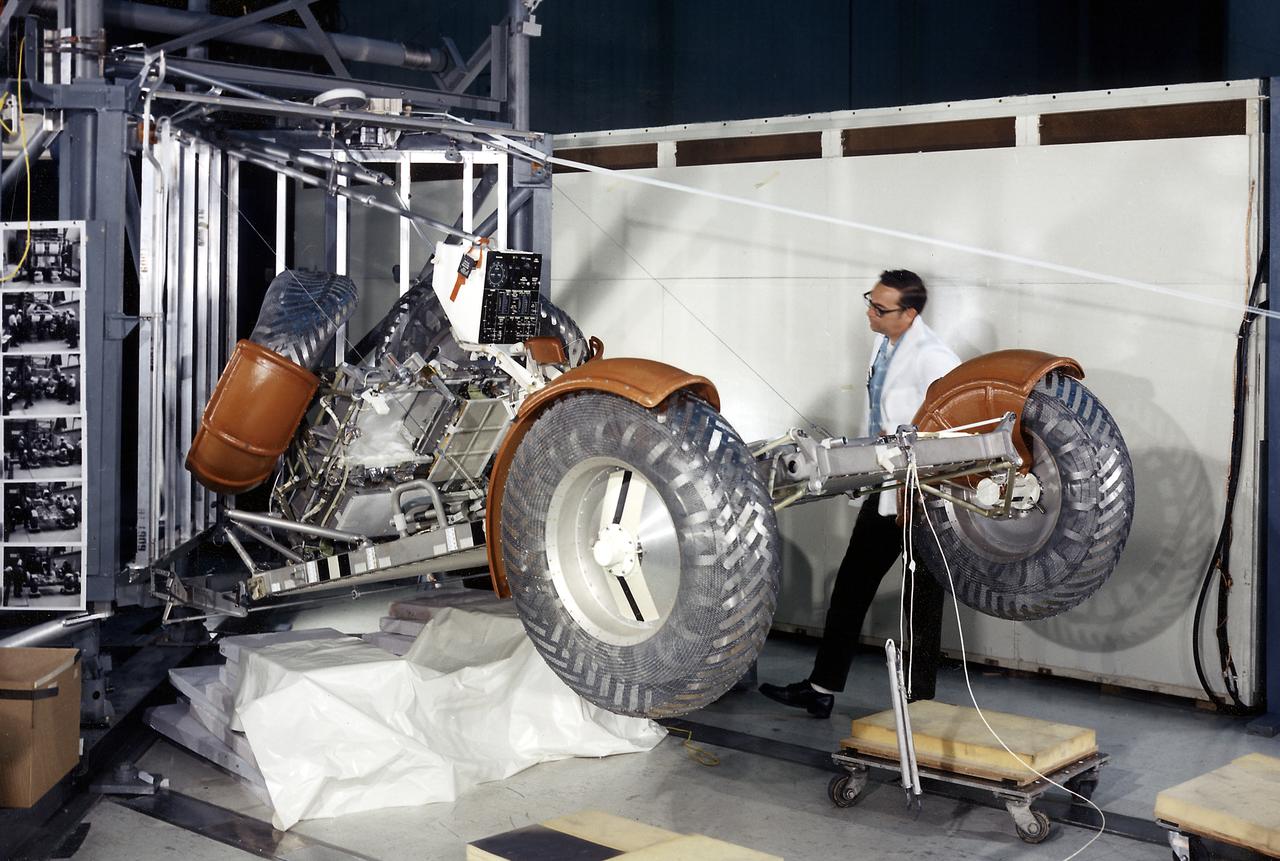
This photograph was taken during a deployment simulation of the Lunar Roving Vehicle (LRV). The LRV was built to give Apollo astronauts a greater range of mobility during the last three lunar exploration missions; Apollo 15, Apollo 16, and Apollo 17. It was designed and developed by the Marshall Space Flight Center and built by the Boeing Company.

This photograph was taken during a deployment simulation of the Lunar Roving Vehicle (LRV). The LRV was built to give Apollo astronauts a greater range of mobility during the last three lunar exploration missions; Apollo 15, Apollo 16, and Apollo 17. It was designed and developed by the Marshall Space Flight Center and built by the Boeing Company.

This in an aerial view (looking north) of a Lunar Roving Vehicle (LRV), often referrd to as “Moonbuggy”, simulator area built at the Marshall Space Flight Center (MSFC) where tesing was performed. The LRV was developed under the direction of MSFC to provide astronauts with greater mobility on the lunar surface.
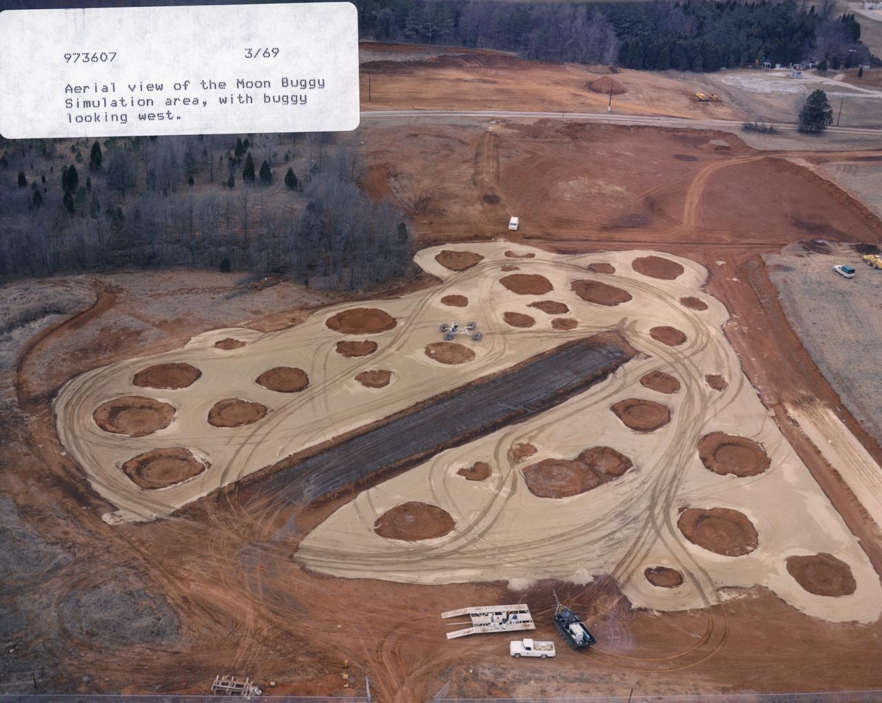
This in an aerial view (looking west) of a Lunar Roving Vehicle (LRV), often referred to as “Moonbuggy”, simulator area built at the Marshall Space Flight Center (MSFC) where tesing was performed. The LRV was developed under the direction of MSFC to provide astronauts with greater mobility on the lunar surface.
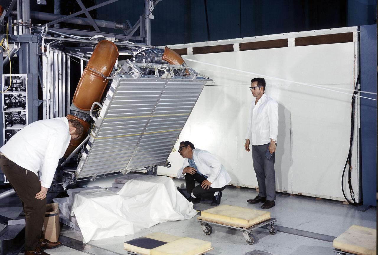
This photograph was taken during a deployment simulation of the Lunar Roving Vehicle (LRV). The LRV was built to give Apollo astronauts a greater range of mobility during the last three lunar exploration missions; Apollo 15, Apollo 16, and Apollo 17. It was designed and developed by the Marshall Space Flight Center and built by the Boeing Company.
The Simulated Lunar Operations Lab at NASA Glenn Research Center serve to test planetary roving vehicle systems and components in simulated planetary and lunar conditions such as the VIPER Rover.

This in an aerial view (looking east) of a Lunar Roving Vehicle (LRV), often referred to as “Moonbuggy”, simulator area built at the Marshall Space Flight Center (MSFC) where testing was performed. The LRV was developed under the direction of MSFC to provide astronauts with greater mobility on the lunar surface. Visible in the background is the 18-acre facility known as the Random Motion/ Lift-Off Simulator or ‘Arm Farm’ which was developed to test the Saturn swingarm mechanisms that were used to hold the rocket in position until lift-off.
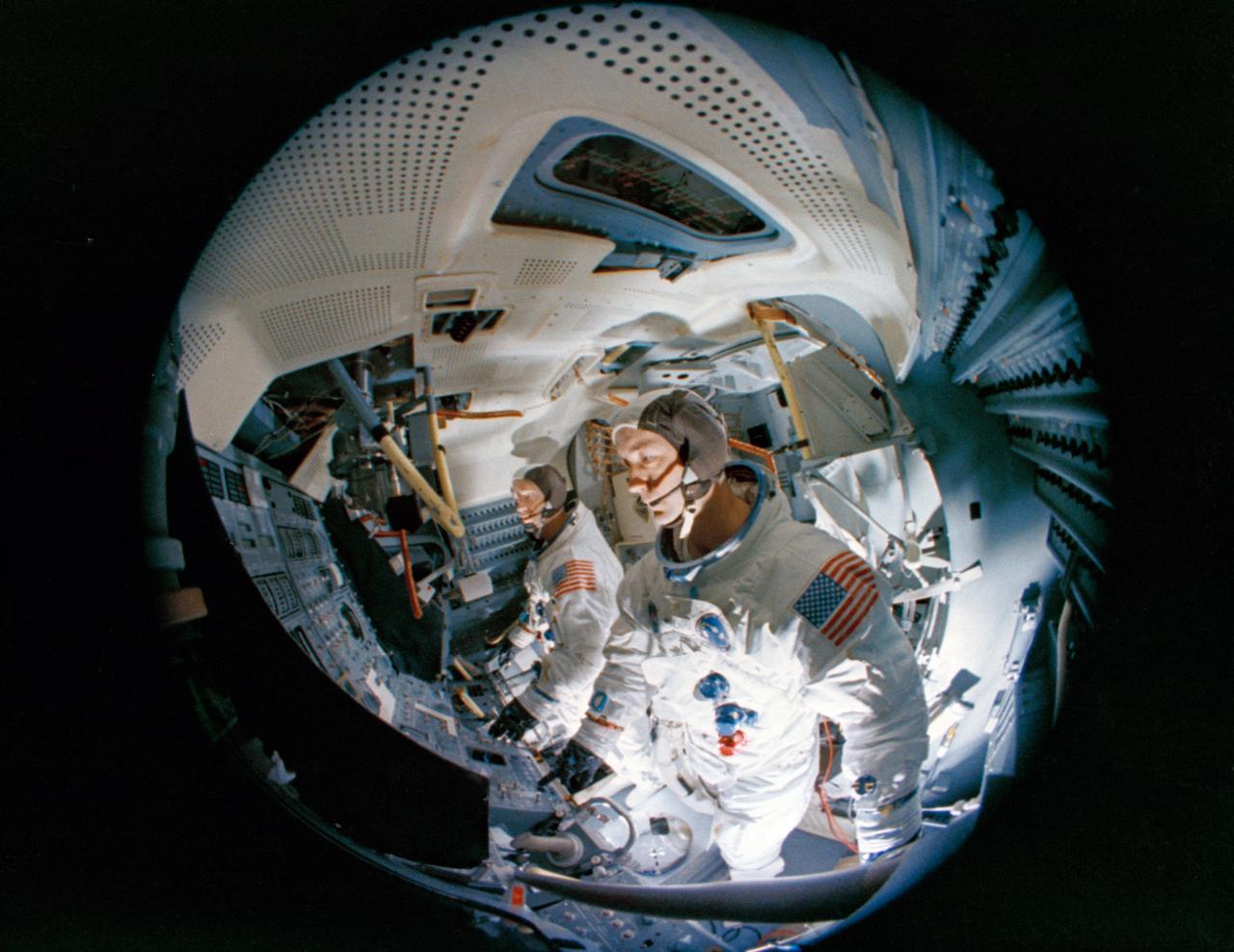
S69-19981 (23 Feb. 1969) --- Fish-eye camera lens view of the interior of the Apollo Lunar Module Mission Simulator (LMMS) at the Kennedy Space Center (KSC) during Apollo 9 simulation training. In the foreground is astronaut James A. McDivitt, prime crew commander; and in background is astronaut Russell L. Schweickart, lunar module pilot.
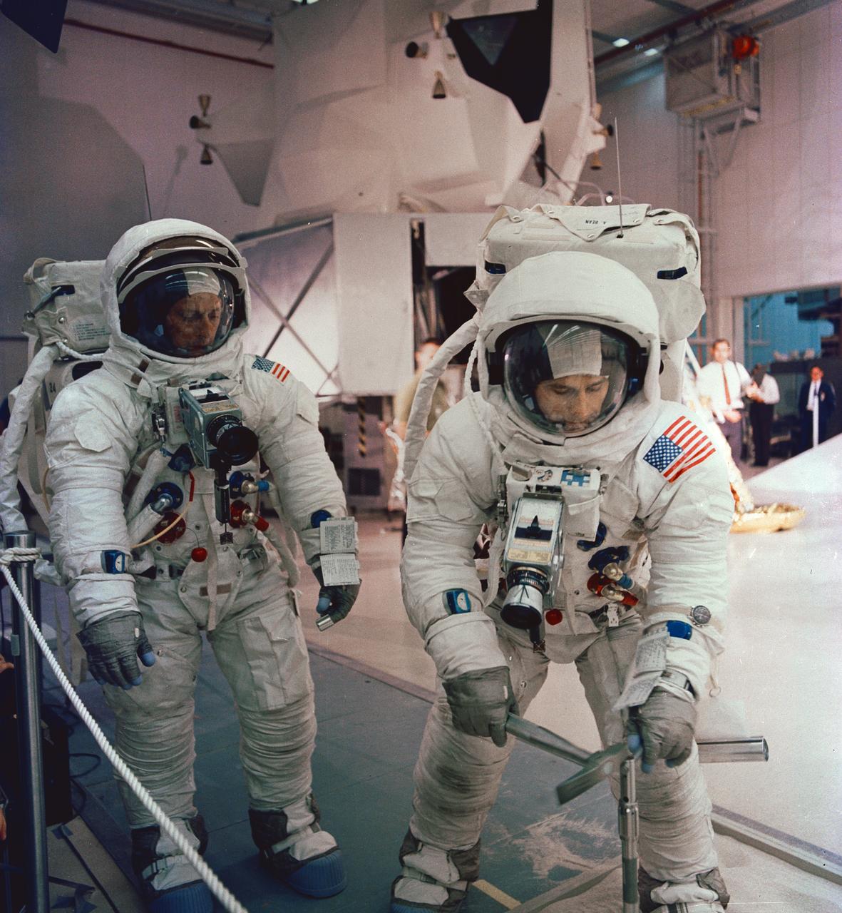
S69-55362 (6 Oct. 1969) --- The two assigned moon-walking crew members for the Apollo 12 lunar landing mission participate in lunar surface extravehicular activity simulations in the Kennedy Space Center's Flight Crew Training Building. Here, astronaut Alan L. Bean, lunar module pilot, simulates driving core tube into lunar surface to obtain a sample. Astronaut Charles Conrad Jr., commander, looks on. A Lunar Module mock-up is in the center background. Photo credit: NASA or National Aeronautics and Space Administration
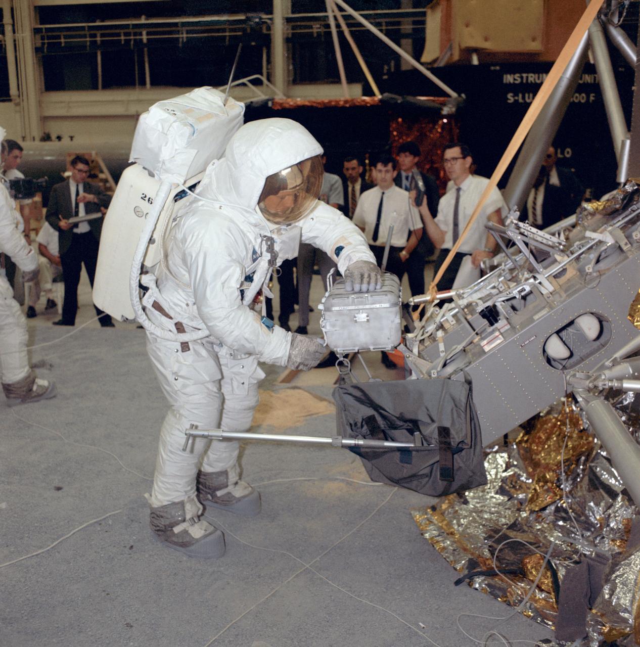
S69-31080 (18 April 1969) --- Suited astronaut Neil A. Armstrong, wearing an Extravehicular Mobility Unit (EMU), participates in lunar surface simulation training on April 18, 1969 in building 9, Manned Spacecraft Center (MSC). Armstrong is prime crew commander of the Apollo 11 lunar landing mission. Here, he is opening a sample return container. On the right is the Modular Equipment Stowage Assembly (MESA) and the Lunar Module (LM) mock-up.
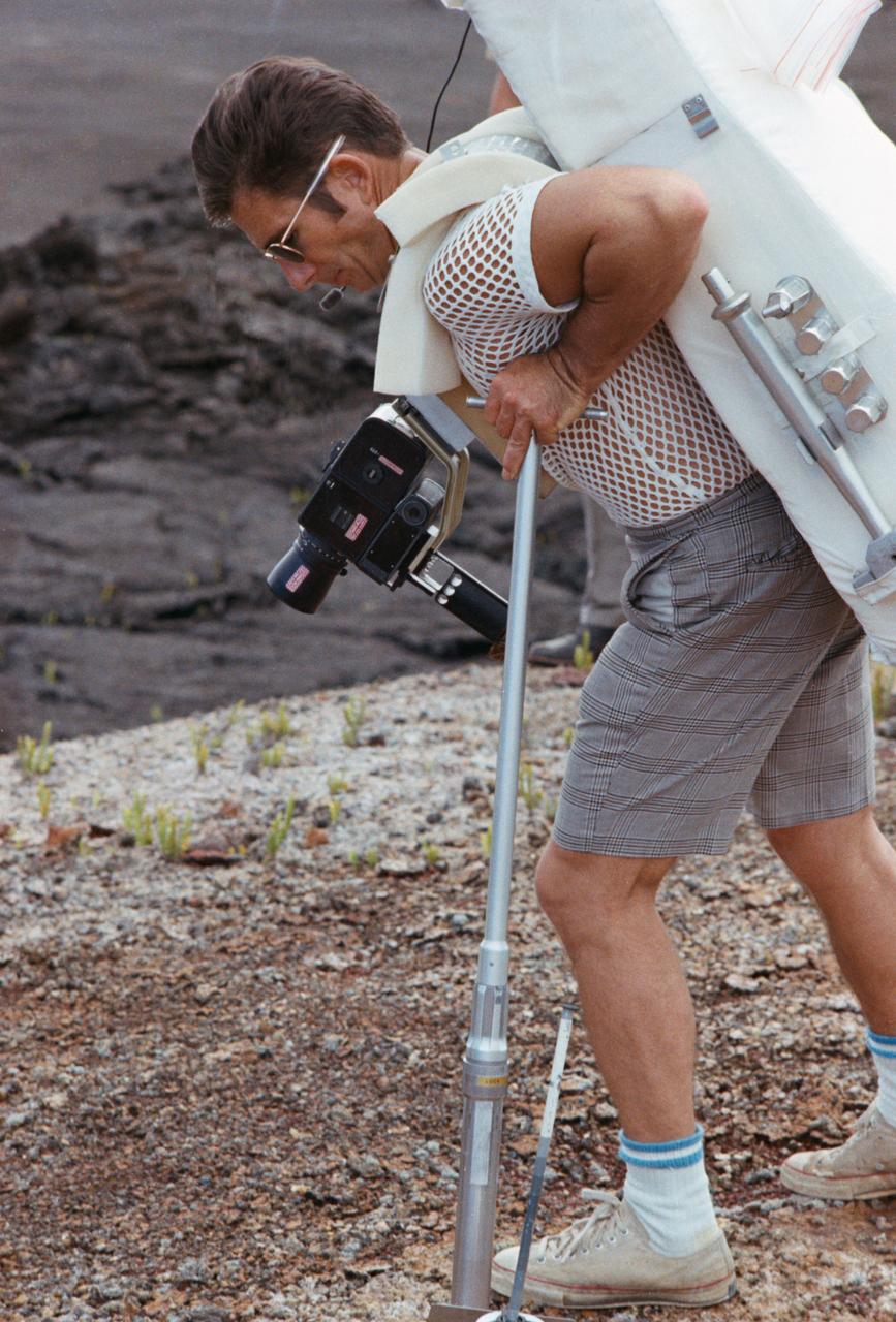
S70-56433 (December 1970) --- Astronaut James B. Irwin, lunar module pilot of the Apollo 15 lunar landing mission, participates in lunar surface extravehicular activity (EVA) training during a visit to Hawaii. He is simulating using lunar surface geological tools to collect a core sample.
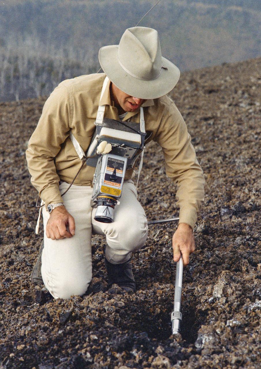
S70-20272 (December 1969) --- Astronaut James A. Lovell Jr., commander of the upcoming Apollo 13 lunar landing mission, uses a scoop from the Apollo Lunar Hand Tools (ALHT) during a simulated lunar surface traverse at the Kapoho, Hawaii training site. While at the Hawaii training sites, Lovell and Haise are participating in thorough rehearsals of their extravehicular activity (EVA). Photo credit: NASA
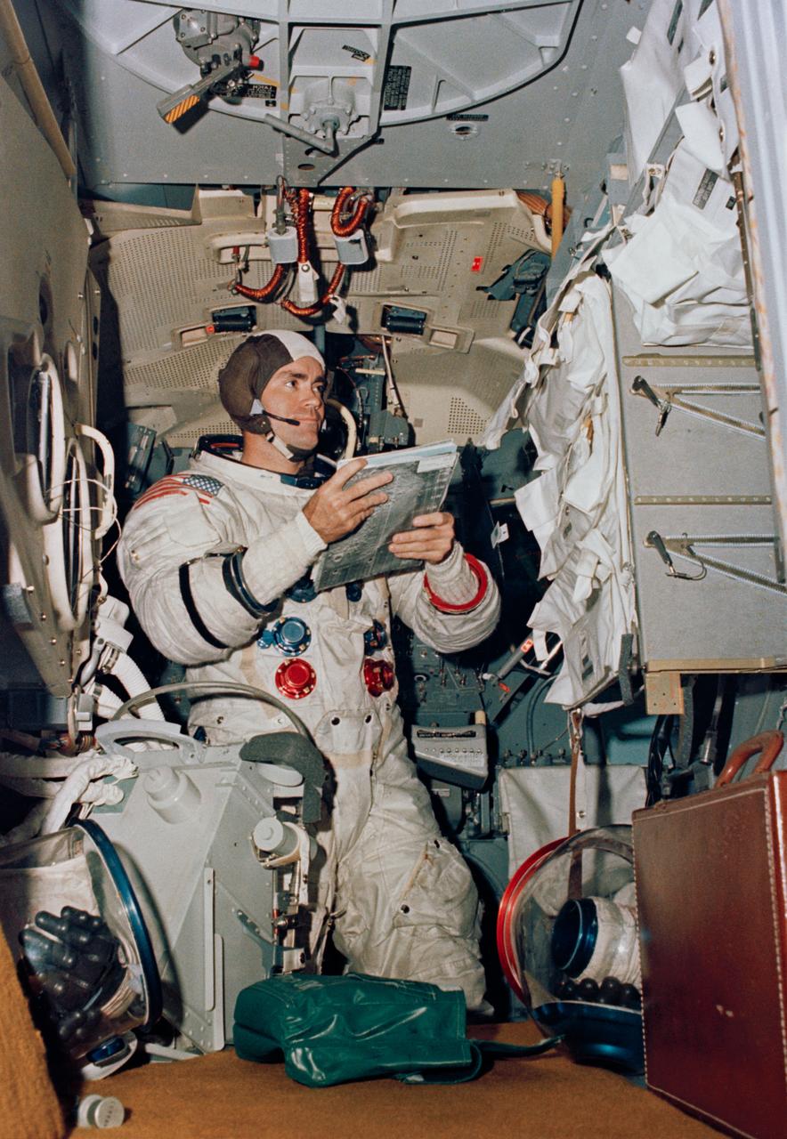
S70-34412 (4 April 1970) --- Astronaut Fred W. Haise Jr., Apollo 13 lunar module pilot, participates in simulation training in preparation for the scheduled lunar landing mission. He is in the Apollo Lunar Module Mission Simulator in the Kennedy Space Center's Flight Crew Training building.
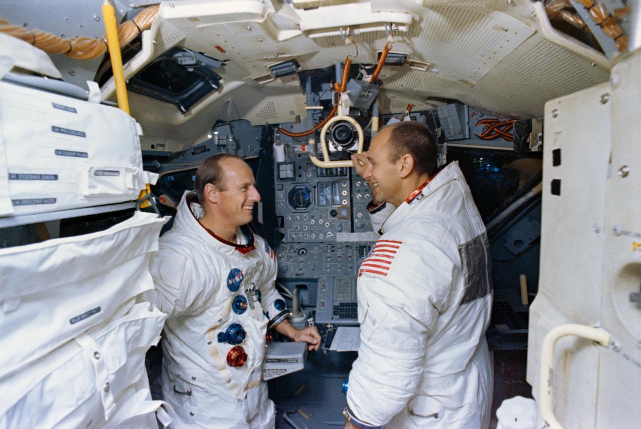
S69-56699 (22 Oct. 1969) --- Astronauts Charles Conrad Jr. (left), Apollo 12 commander; and Alan L. Bean, lunar module pilot, are shown in the Apollo Lunar Module Mission Simulator during simulator training at the Kennedy Space Center (KSC). Apollo 12 will be the National Aeronautics and Space Administration's (NASA) second lunar landing mission. The third Apollo 12 crewmember will be astronaut Richard F. Gordon Jr., command module pilot.
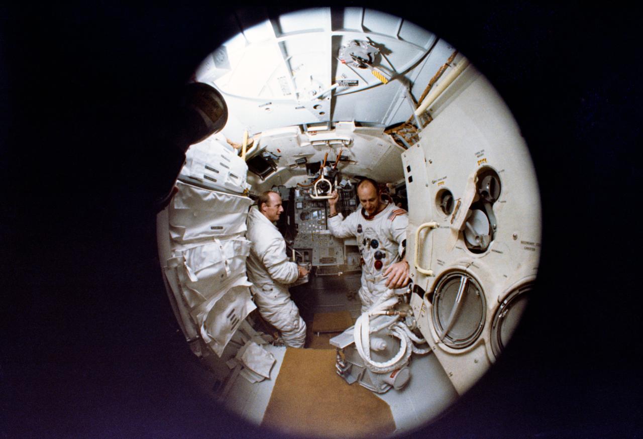
S69-56700 (22 Oct. 1969) --- A fish-eye lens view of astronauts Charles Conrad Jr. (on left), Apollo 12 commander, and Alan L. Bean, lunar module pilot, inside the Apollo Lunar Module Mission Simulator during simulator training at the Kennedy Space Center (KSC). Apollo 12 will be the National Aeronautics and Space Administration's (NASA) second lunar landing mission. The third Apollo 12 crewmember will be astronaut Richard F. Gordon Jr., command module pilot.
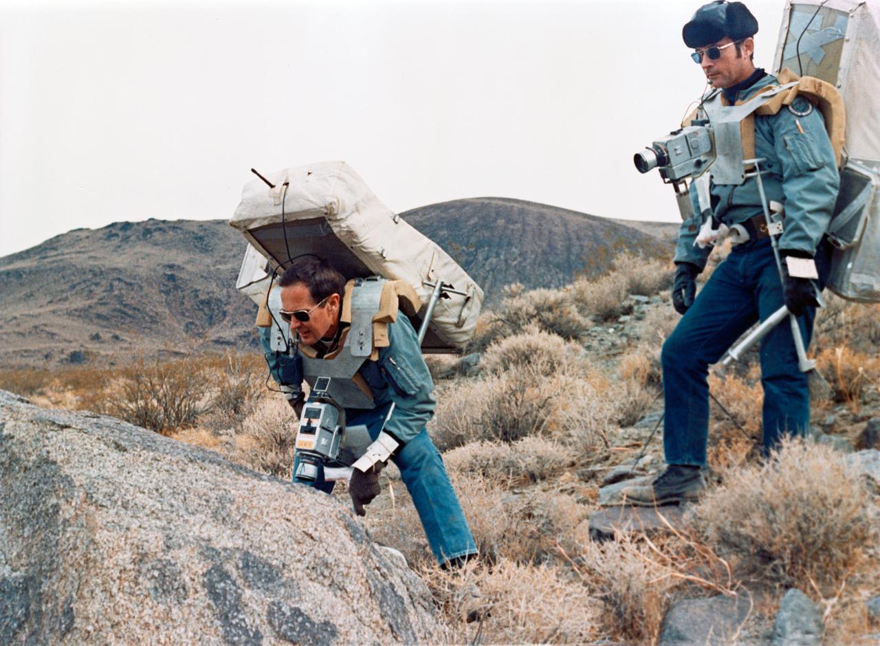
S71-59355 (17-18 Nov. 1971) --- Astronauts John W. Young, right, prime crew commander for Apollo 16, and Charles M. Duke Jr., lunar module pilot, study rock formations along their simulated lunar traverse route. The prime and backup commanders and lunar module pilots for Apollo 16 took part in the two-day geology field trip and simulations in the Coso Range, near Ridgecrest, California, about 160 miles north by northeast of Los Angeles. The training and simulations were conducted Nov. 17 and 18, 1971, at the U.S. Naval Ordnance Test Station.
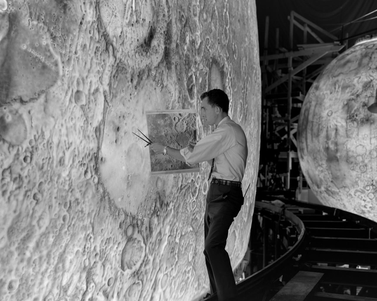
Artists used paintbrushes and airbrushes to recreate the lunar surface on each of the four models comprising the LOLA simulator. Project LOLA or Lunar Orbit and Landing Approach was a simulator built at Langley to study problems related to landing on the lunar surface. It was a complex project that cost nearly 2 million dollars. James Hansen wrote: This simulator was designed to provide a pilot with a detailed visual encounter with the lunar surface the machine consisted primarily of a cockpit, a closed-circuit TV system, and four large murals or scale models representing portions of the lunar surface as seen from various altitudes. The pilot in the cockpit moved along a track past these murals which would accustom him to the visual cues for controlling a spacecraft in the vicinity of the moon. Unfortunately, such a simulation--although great fun and quite aesthetic--was not helpful because flight in lunar orbit posed no special problems other than the rendezvous with the LEM, which the device did not simulate. Not long after the end of Apollo, the expensive machine was dismantled. (p. 379) Ellis J. White described the simulator as follows: Model 1 is a 20-foot-diameter sphere mounted on a rotating base and is scaled 1 in. 9 miles. Models 2,3, and 4 are approximately 15x40 feet scaled sections of model 1. Model 4 is a scaled-up section of the Crater Alphonsus and the scale is 1 in. 200 feet. All models are in full relief except the sphere. -- Published in James R. Hansen, Spaceflight Revolution: NASA Langley Research Center From Sputnik to Apollo, (Washington: NASA, 1995), p. 379 Ellis J. White, Discussion of Three Typical Langley Research Center Simulation Programs, Paper presented at the Eastern Simulation Council (EAI s Princeton Computation Center), Princeton, NJ, October 20, 1966.
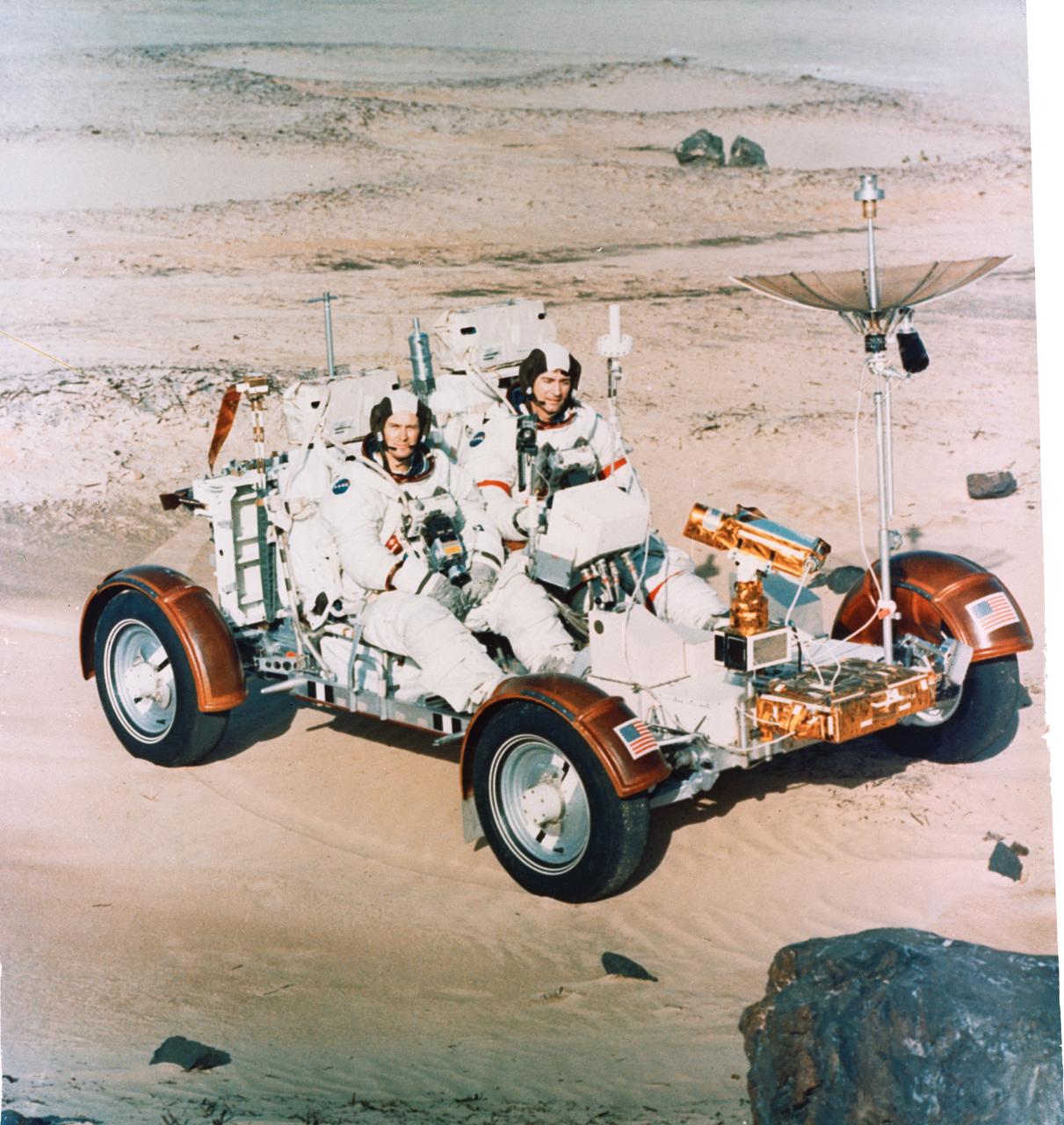
S72-30695 (22 Dec. 1971) --- Astronauts John W. Young, right, Apollo 16 commander, and Charles M. Duke Jr., lunar module pilot, maneuver a training version of the Lunar Roving Vehicle (LRV) about a field at Kennedy Space Center (KSC) simulated to represent the lunar surface. The LRV is planned to transport the two crew men around the Descartes area on the lunar surface while astronaut Thomas K. Mattingly II, command module pilot, orbits the moon in the Command and Service Modules (CSM).
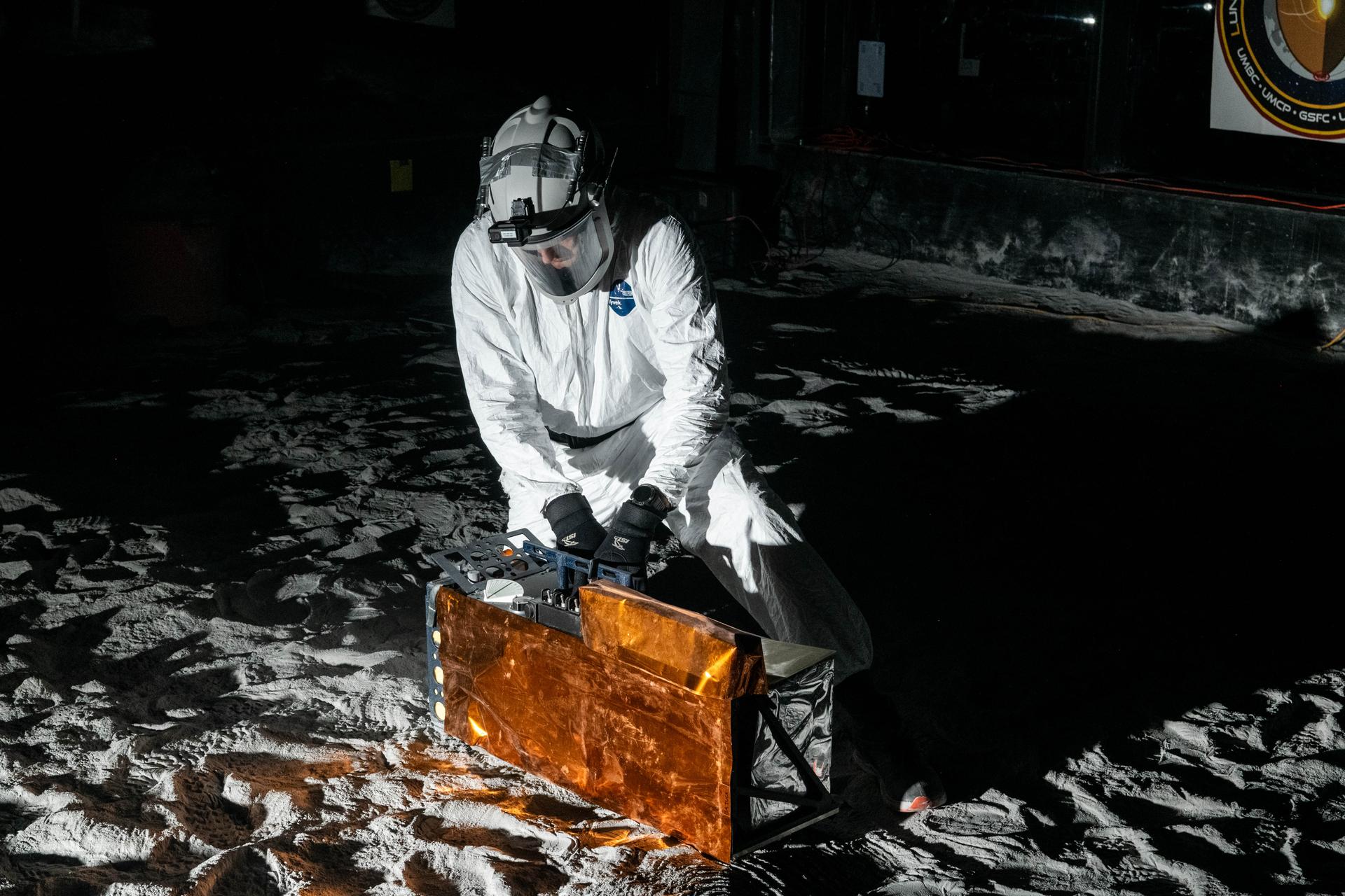
Artemis Scientist, Trevor Graff, performs instrument deployment exercises with a medium fidelity mock up of the Lunar Environment Monitoring Station (LEMS) in the lunar simulant bin at the Florida Space Institute Exolith Lab, Orlando, Fl., Aug 6, 2025. LEMS is a compact, autonomous, and self-sustaining seismometer suite designed to carry out continuous, long-term, monitoring of the lunar seismic environment at the South Polar region. Photo Credit: NASA/Katie Mellos.
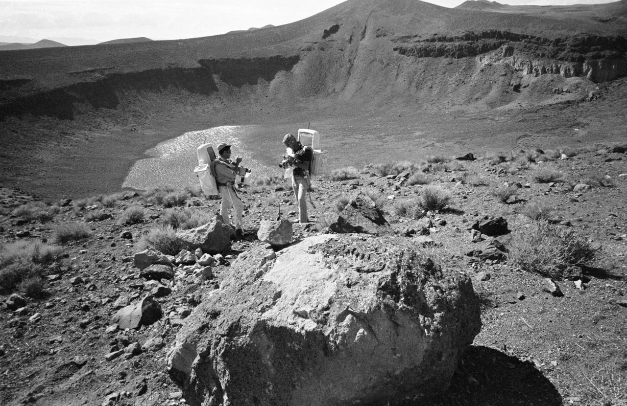
S72-48854 (6 Sept. 1972) --- Two members of the prime crew of the Apollo 17 lunar landing mission examine rock specimens during lunar surface extravehicular activity simulation training on a geological field trip to the Pancake Range area of south-central Nevada. They are astronaut Eugene A. Cernan (right), commander; and scientist-astronaut Harrison H. Schmitt, lunar module pilot. They are standing on the rim of Lunar Crater, which is about 600 feet deep and five-eighths of a mile in diameter. It is a volcanic crater.
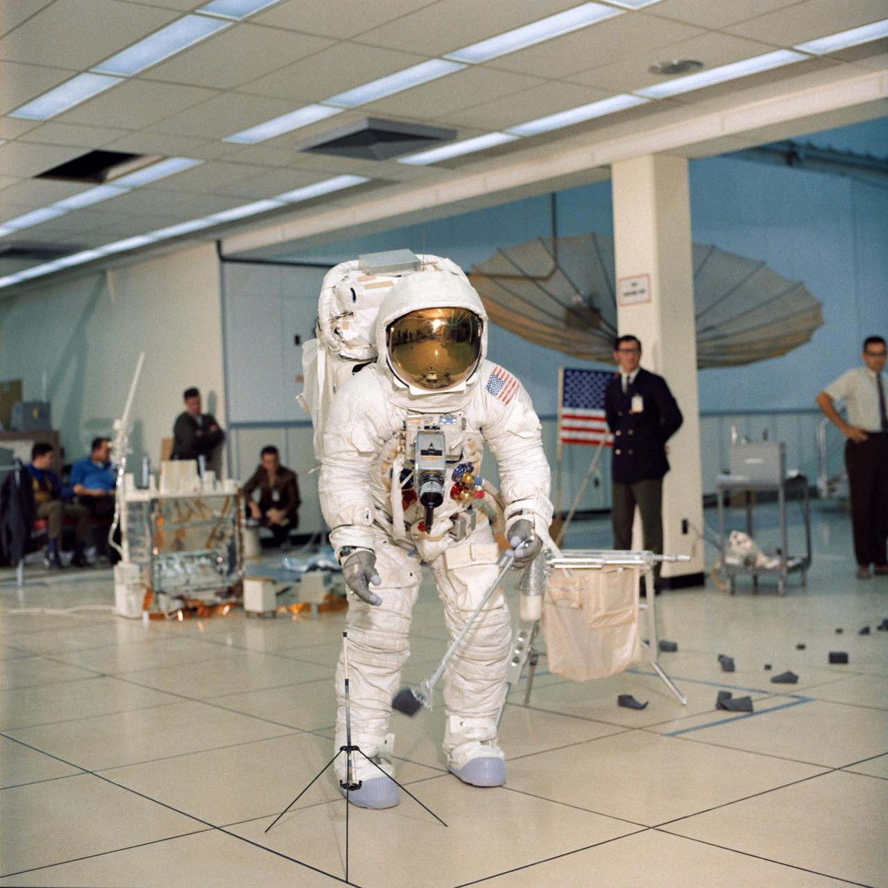
S70-27037 (4 Feb. 1970) --- Astronaut James A. Lovell Jr., commander of the Apollo 13 lunar landing mission, simulates lunar surface extravehicular activity during training exercises in the Kennedy Space Center’s Flight Crew Training Building. Lovell, wearing an Extravehicular Mobility Unit (EMU), is holding an Apollo Lunar Hand Tool (a set of tongs) in his left hand. A gnomon is in front of his right foot. A tool carrier is in the right background.
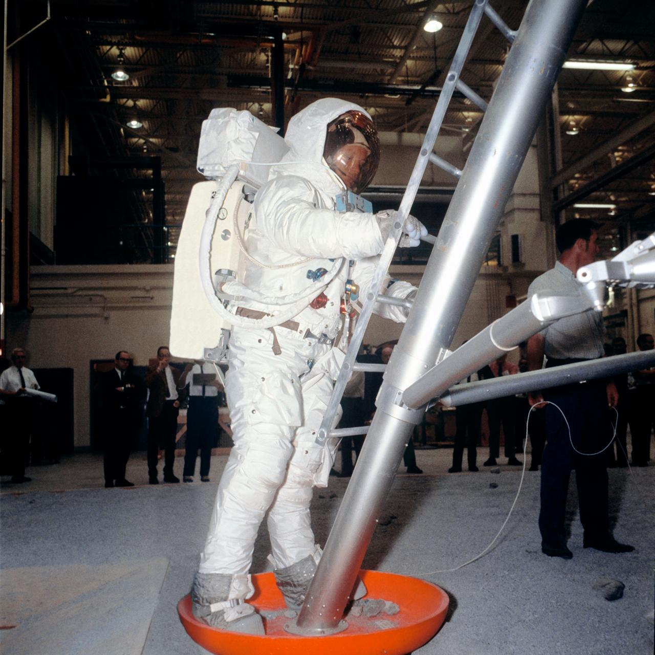
S69-31042 (18 April 1969) --- Suited astronaut Neil A. Armstrong, wearing an Extravehicular Mobility Unit (EMU), participates in lunar surface simulation training on April 18, 1969, in Building 9, Manned Spacecraft Center (MSC). Armstrong is the prime crew commander of the Apollo 11 lunar landing mission. Here, he is standing on Lunar Module (LM) mockup foot pad preparing to ascend steps.
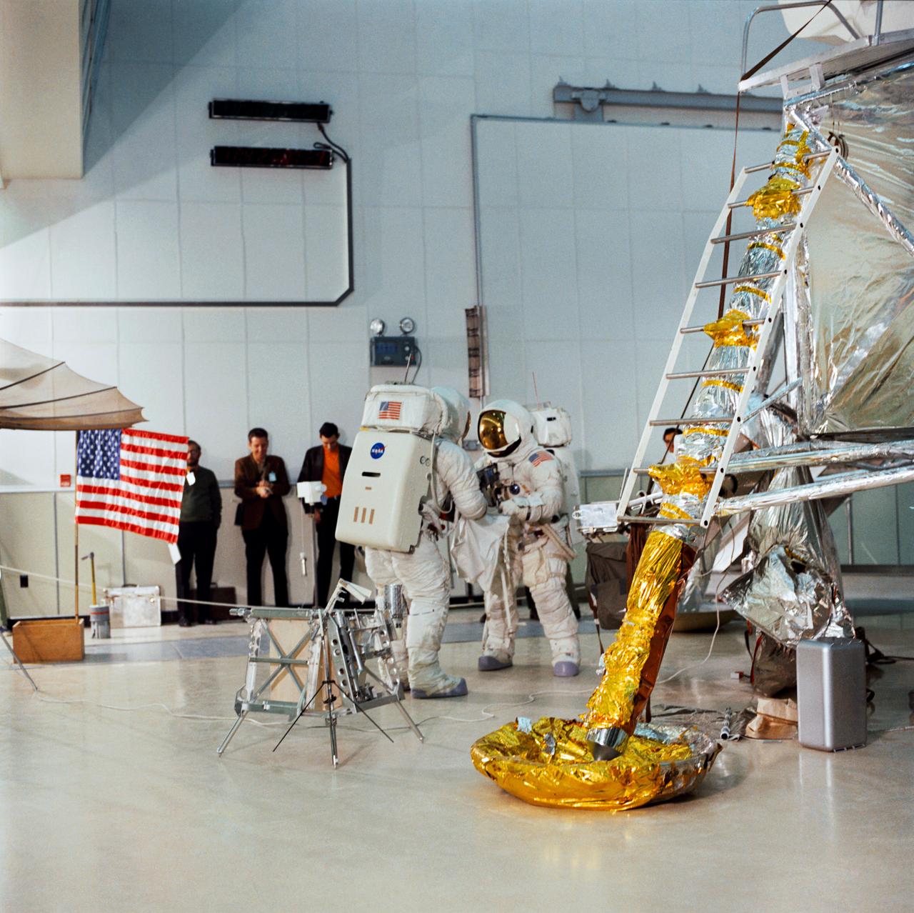
S70-27038 (4 Feb. 1970) --- Two crew men of the Apollo 13 lunar landing mission simulate lunar surface Extravehicular Activity (EVA) during training exercises in the Kennedy Space Center's (KSC) Flight Crew Training Building. They are astronauts James A. Lovell Jr. (on left, back to camera) commander; and Fred W. Haise Jr., lunar module pilot.
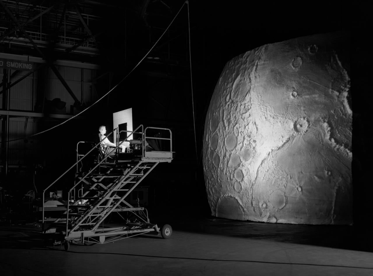
Test subject sitting at the controls: Project LOLA or Lunar Orbit and Landing Approach was a simulator built at Langley to study problems related to landing on the lunar surface. It was a complex project that cost nearly $2 million dollars. James Hansen wrote: "This simulator was designed to provide a pilot with a detailed visual encounter with the lunar surface; the machine consisted primarily of a cockpit, a closed-circuit TV system, and four large murals or scale models representing portions of the lunar surface as seen from various altitudes. The pilot in the cockpit moved along a track past these murals which would accustom him to the visual cues for controlling a spacecraft in the vicinity of the moon. Unfortunately, such a simulation--although great fun and quite aesthetic--was not helpful because flight in lunar orbit posed no special problems other than the rendezvous with the LEM, which the device did not simulate. Not long after the end of Apollo, the expensive machine was dismantled." (p. 379) Ellis J. White further described this simulator in his paper , "Discussion of Three Typical Langley Research Center Simulation Programs," (Paper presented at the Eastern Simulation Council (EAI's Princeton Computation Center), Princeton, NJ, October 20, 1966.) "A typical mission would start with the first cart positioned on model 1 for the translunar approach and orbit establishment. After starting the descent, the second cart is readied on model 2 and, at the proper time, when superposition occurs, the pilot's scene is switched from model 1 to model 2. then cart 1 is moved to and readied on model 3. The procedure continues until an altitude of 150 feet is obtained. The cabin of the LM vehicle has four windows which represent a 45 degree field of view. The projection screens in front of each window represent 65 degrees which allows limited head motion before the edges of the display can be seen. The lunar scene is presented to the pilot by rear projection on the screens with four Schmidt television projectors. The attitude orientation of the vehicle is represented by changing the lunar scene through the portholes determined by the scan pattern of four orthicons. The stars are front projected onto the upper three screens with a four-axis starfield generation (starball) mounted over the cabin and there is a separate starball for the low window." -- Published in James R. Hansen, Spaceflight Revolution: NASA Langley Research Center From Sputnik to Apollo, (Washington: NASA, 1995), p. 379.
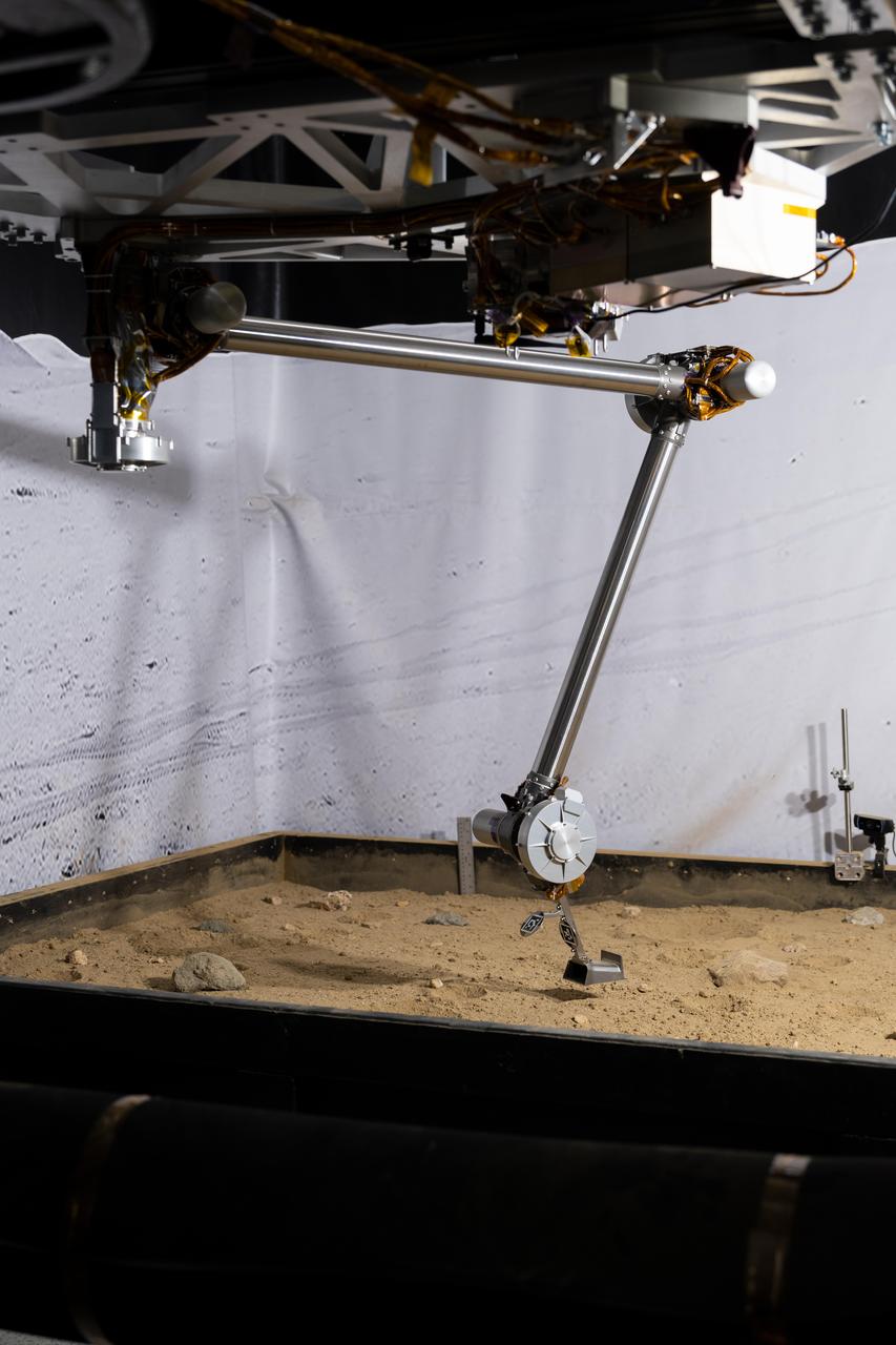
The 3D-printed titanium scoop of the Cold Operable Lunar Deployable Arm (COLDArm) robotic arm system is poised above a test bed filled with material to simulate lunar regolith (broken rocks and dust) at NASA's Jet Propulsion Laboratory in Southern California. COLDArm can function in temperatures as cold as minus 280 degrees Fahrenheit (minus 173 degrees Celsius). COLDArm is designed to go on a Moon lander and operate during lunar night, a period that lasts about 14 Earth days. Frigid temperatures during lunar night would stymie current spacecraft, which must rely on energy-consuming heaters to stay warm. To operate in the cold, the 6-foot-6-inch (2-meter) arm combines several key new technologies: gears made of bulk metallic glass that require no lubrication or heating, cold motor controllers that don't need to be kept warm in an electronics box near the core of the spacecraft, and a cryogenic six-axis force torque sensor that lets the arm "feel" what it's doing and make adjustments. A variety of attachments and small instruments could go on the end of the arm, including the scoop, which could be used for collecting samples from a planet's surface. Like the arm on NASA's InSight Mars lander, COLDArm could deploy science instruments to the surface. https://photojournal.jpl.nasa.gov/catalog/PIA25317

S71-39867 (June 1971) --- Astronauts David R. Scott (right), commander, and James B. Irwin, lunar module pilot, are shown on the Lunar Roving Vehicle (LRV) at the Kennedy Space Center (KSC), Florida, during Apollo 15 lunar surface extravehicular activity (EVA) simulations. While astronauts Scott and Irwin descend in the Lunar Module (LM) "Falcon" to explore the moon, astronaut Alfred M. Worden, command module pilot, will remain with the Command and Service Modules (CSM) in lunar orbit.
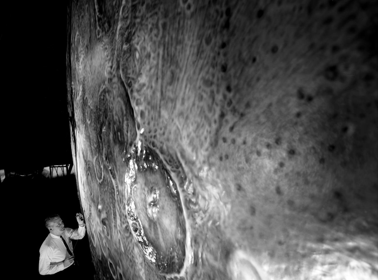
Artists used paintbrushes and airbrushes to recreate the lunar surface on each of the four models comprising the LOLA simulator. Project LOLA or Lunar Orbit and Landing Approach was a simulator built at Langley to study problems related to landing on the lunar surface. It was a complex project that cost nearly $2 million dollars. James Hansen wrote: "This simulator was designed to provide a pilot with a detailed visual encounter with the lunar surface; the machine consisted primarily of a cockpit, a closed-circuit TV system, and four large murals or scale models representing portions of the lunar surface as seen from various altitudes. The pilot in the cockpit moved along a track past these murals which would accustom him to the visual cues for controlling a spacecraft in the vicinity of the moon. Unfortunately, such a simulation--although great fun and quite aesthetic--was not helpful because flight in lunar orbit posed no special problems other than the rendezvous with the LEM, which the device did not simulate. Not long after the end of Apollo, the expensive machine was dismantled." (p. 379) Ellis J. White further described LOLA in his paper "Discussion of Three Typical Langley Research Center Simulation Programs," "Model 1 is a 20-foot-diameter sphere mounted on a rotating base and is scaled 1 in. = 9 miles. Models 2,3, and 4 are approximately 15x40 feet scaled sections of model 1. Model 4 is a scaled-up section of the Crater Alphonsus and the scale is 1 in. = 200 feet. All models are in full relief except the sphere." -- Published in James R. Hansen, Spaceflight Revolution: NASA Langley Research Center From Sputnik to Apollo, (Washington: NASA, 1995), p. 379; Ellis J. White, "Discussion of Three Typical Langley Research Center Simulation Programs," Paper presented at the Eastern Simulation Council (EAI's Princeton Computation Center), Princeton, NJ, October 20, 1966.
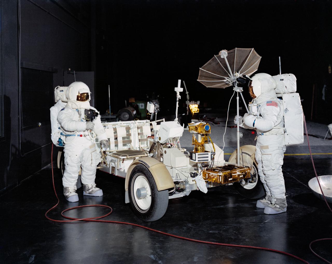
S71-16722 (January 1971) --- Two members of the prime crew of the Apollo 15 lunar landing mission are shown with the Lunar Roving Vehicle "one G" trainer in Building 5, Mission Simulation and Training Facility, Manned Spacecraft Center. Astronaut David R. Scott (on right) is the Apollo 15 commander; and astronaut James B. Irwin is the lunar module pilot. A Lunar Roving Vehicle similar to this trainer will be used by Scott and Irwin during their Apollo 15 lunar surface extravehicular activity.
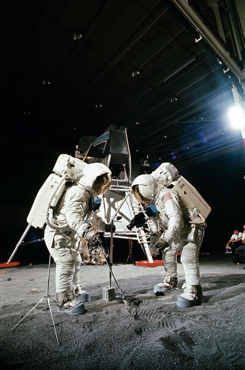
Two members of the Apollo 11 lunar landing mission participate in a simulation of deploying and using lunar tools on the surface of the moon during a training exercise in bldg 9 on April 22, 1969. Astronaut Edwin E. Aldrin Jr. (on left), lunar module pilot, uses scoop and tongs to pick up sample. Astronaut Neil A. Armstrong, Apollo 11 commander, holds bag to receive sample. In the background is a Lunar Module mockup. Both men are wearing Extravehicular Mobility Units (EMU).
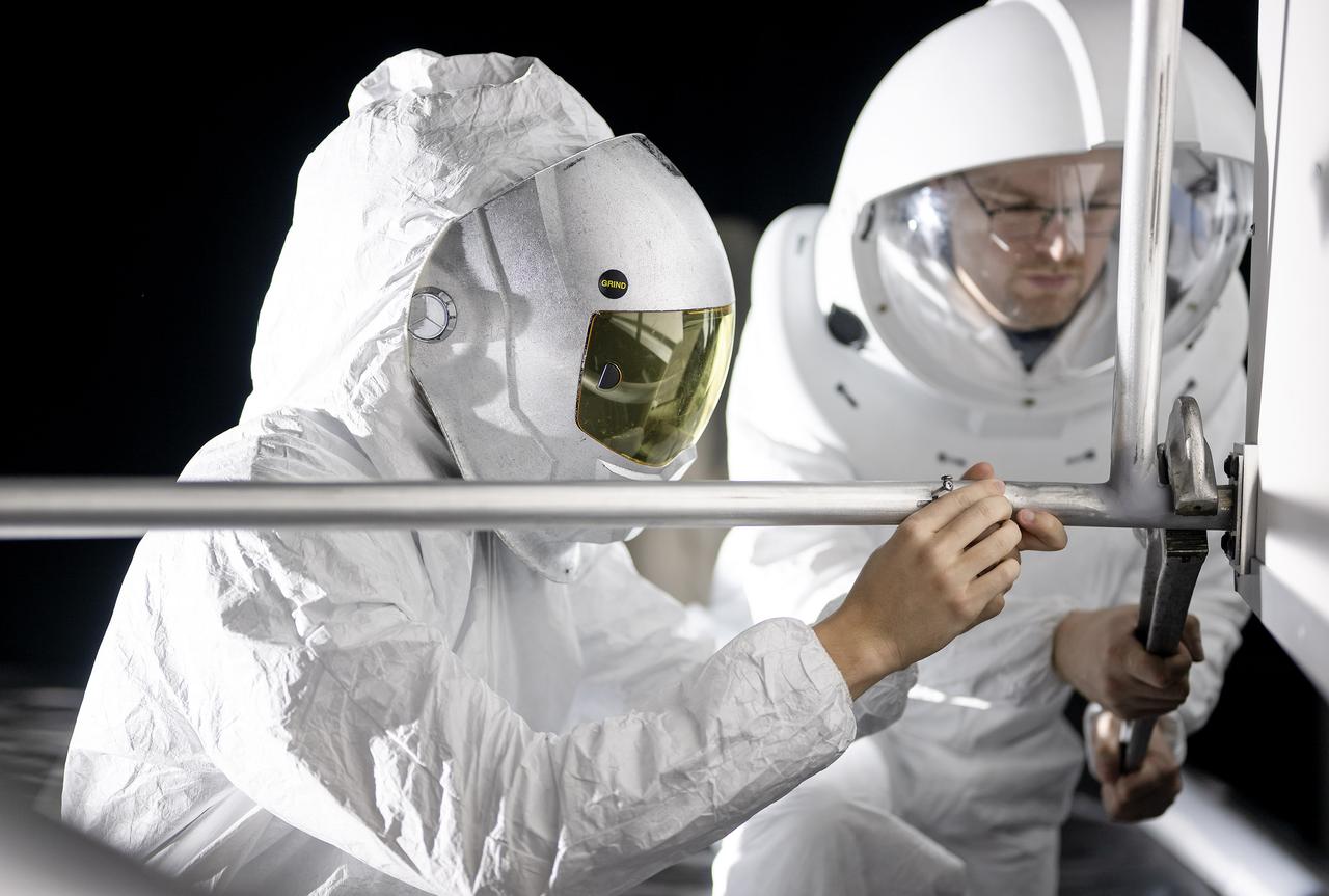
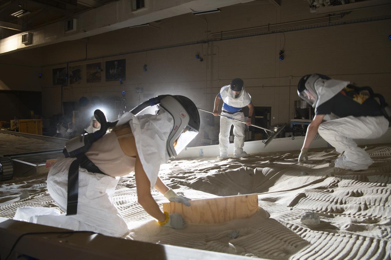
These photos show how teams at NASA’s Marshall Space Flight Center in Huntsville, Alabama, are using the Flat Floor Facility (Building 4619) to understand the lunar lighting environment in preparation for the Artemis III crewed lunar landing mission, slated for 2027. The Flat Floor Facility is an air-bearing floor, providing full-scale simulation capabilities for lunar surface systems by simulating zero gravity in two dimensions. Wearing low-fidelity materials, test engineers can understand how the extreme lighting of the Moon’s South Pole could affect surface operations during Artemis III. High-intensity lights are positioned at a low angle to replicate the strong shadows that are cast across the lunar South Pole by the Sun. Data and analysis from testing at NASA Marshall are improving models Artemis astronauts will use in preparation for lander and surface operations on the Moon during Artemis III. Testing in the facility is also helping cross-agency teams evaluate various tools astronauts may use. NASA Marshall manages the Human Landing System (HLS) Program. For more information, contact NASA Marshall’s Office of Communications at 256-544-0034.
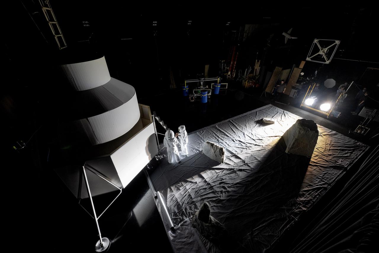
These photos show how teams at NASA’s Marshall Space Flight Center in Huntsville, Alabama, are using the Flat Floor Facility (Building 4619) to understand the lunar lighting environment in preparation for the Artemis III crewed lunar landing mission, slated for 2027. The Flat Floor Facility is an air-bearing floor, providing full-scale simulation capabilities for lunar surface systems by simulating zero gravity in two dimensions. Wearing low-fidelity materials, test engineers can understand how the extreme lighting of the Moon’s South Pole could affect surface operations during Artemis III. High-intensity lights are positioned at a low angle to replicate the strong shadows that are cast across the lunar South Pole by the Sun. Data and analysis from testing at NASA Marshall are improving models Artemis astronauts will use in preparation for lander and surface operations on the Moon during Artemis III. Testing in the facility is also helping cross-agency teams evaluate various tools astronauts may use. NASA Marshall manages the Human Landing System (HLS) Program. For more information, contact NASA Marshall’s Office of Communications at 256-544-0034.
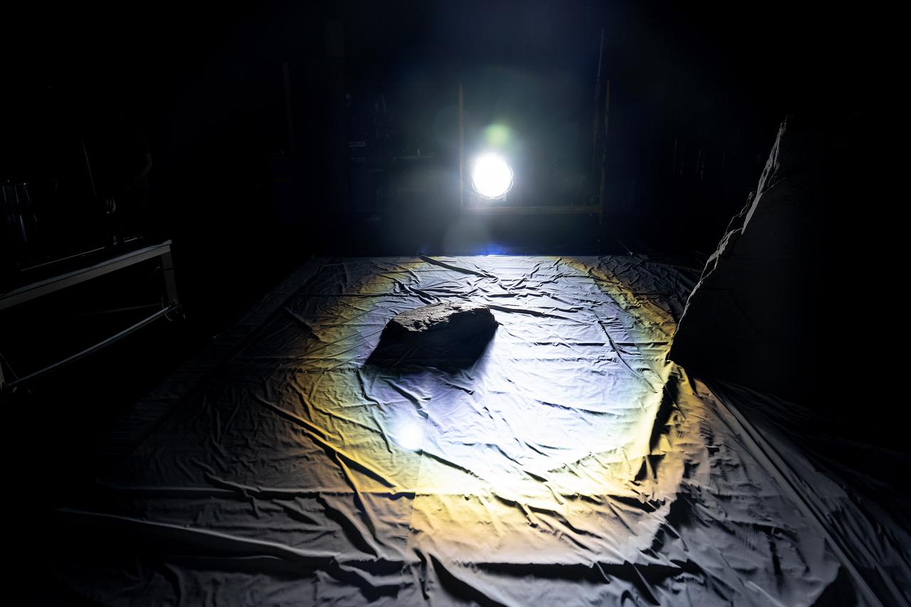
These photos show how teams at NASA’s Marshall Space Flight Center in Huntsville, Alabama, are using the Flat Floor Facility (Building 4619) to understand the lunar lighting environment in preparation for the Artemis III crewed lunar landing mission, slated for 2027. The Flat Floor Facility is an air-bearing floor, providing full-scale simulation capabilities for lunar surface systems by simulating zero gravity in two dimensions. Wearing low-fidelity materials, test engineers can understand how the extreme lighting of the Moon’s South Pole could affect surface operations during Artemis III. High-intensity lights are positioned at a low angle to replicate the strong shadows that are cast across the lunar South Pole by the Sun. Data and analysis from testing at NASA Marshall are improving models Artemis astronauts will use in preparation for lander and surface operations on the Moon during Artemis III. Testing in the facility is also helping cross-agency teams evaluate various tools astronauts may use. NASA Marshall manages the Human Landing System (HLS) Program. For more information, contact NASA Marshall’s Office of Communications at 256-544-0034.
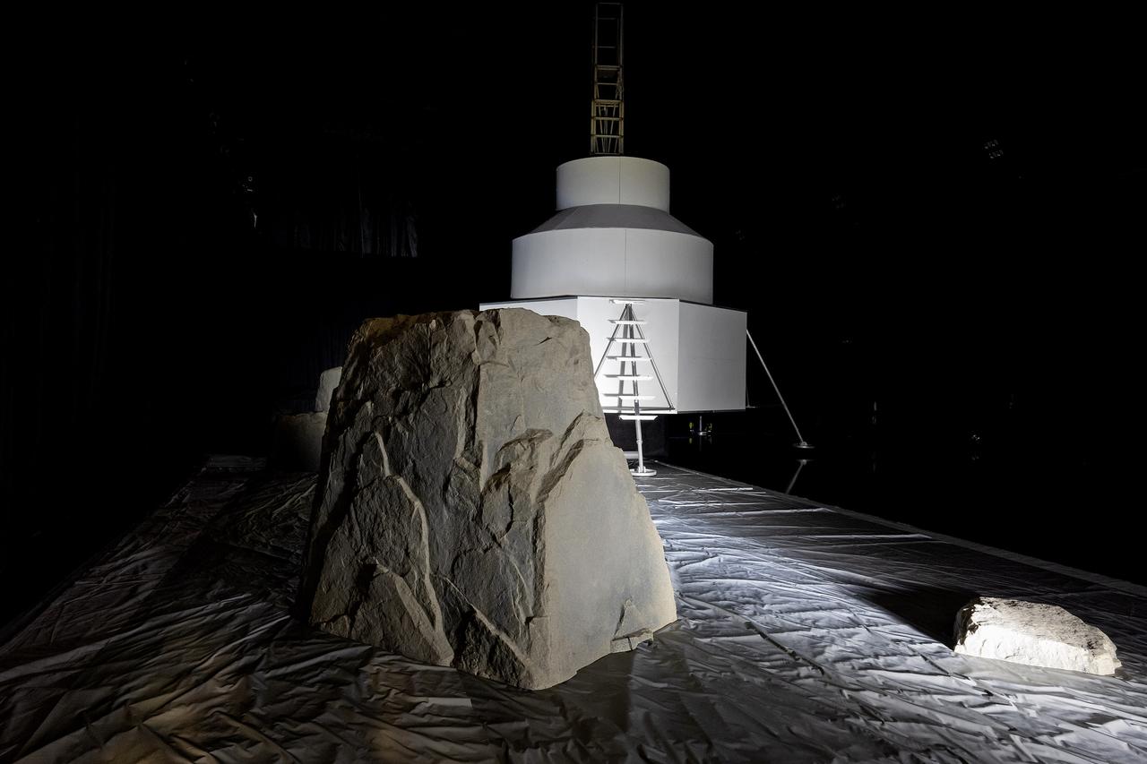
These photos show how teams at NASA’s Marshall Space Flight Center in Huntsville, Alabama, are using the Flat Floor Facility (Building 4619) to understand the lunar lighting environment in preparation for the Artemis III crewed lunar landing mission, slated for 2027. The Flat Floor Facility is an air-bearing floor, providing full-scale simulation capabilities for lunar surface systems by simulating zero gravity in two dimensions. Wearing low-fidelity materials, test engineers can understand how the extreme lighting of the Moon’s South Pole could affect surface operations during Artemis III. High-intensity lights are positioned at a low angle to replicate the strong shadows that are cast across the lunar South Pole by the Sun. Data and analysis from testing at NASA Marshall are improving models Artemis astronauts will use in preparation for lander and surface operations on the Moon during Artemis III. Testing in the facility is also helping cross-agency teams evaluate various tools astronauts may use. NASA Marshall manages the Human Landing System (HLS) Program. For more information, contact NASA Marshall’s Office of Communications at 256-544-0034.
These photos show how teams at NASA’s Marshall Space Flight Center in Huntsville, Alabama, are using the Flat Floor Facility (Building 4619) to understand the lunar lighting environment in preparation for the Artemis III crewed lunar landing mission, slated for 2027. The Flat Floor Facility is an air-bearing floor, providing full-scale simulation capabilities for lunar surface systems by simulating zero gravity in two dimensions. Wearing low-fidelity materials, test engineers can understand how the extreme lighting of the Moon’s South Pole could affect surface operations during Artemis III. High-intensity lights are positioned at a low angle to replicate the strong shadows that are cast across the lunar South Pole by the Sun. Data and analysis from testing at NASA Marshall are improving models Artemis astronauts will use in preparation for lander and surface operations on the Moon during Artemis III. Testing in the facility is also helping cross-agency teams evaluate various tools astronauts may use. NASA Marshall manages the Human Landing System (HLS) Program. For more information, contact NASA Marshall’s Office of Communications at 256-544-0034.

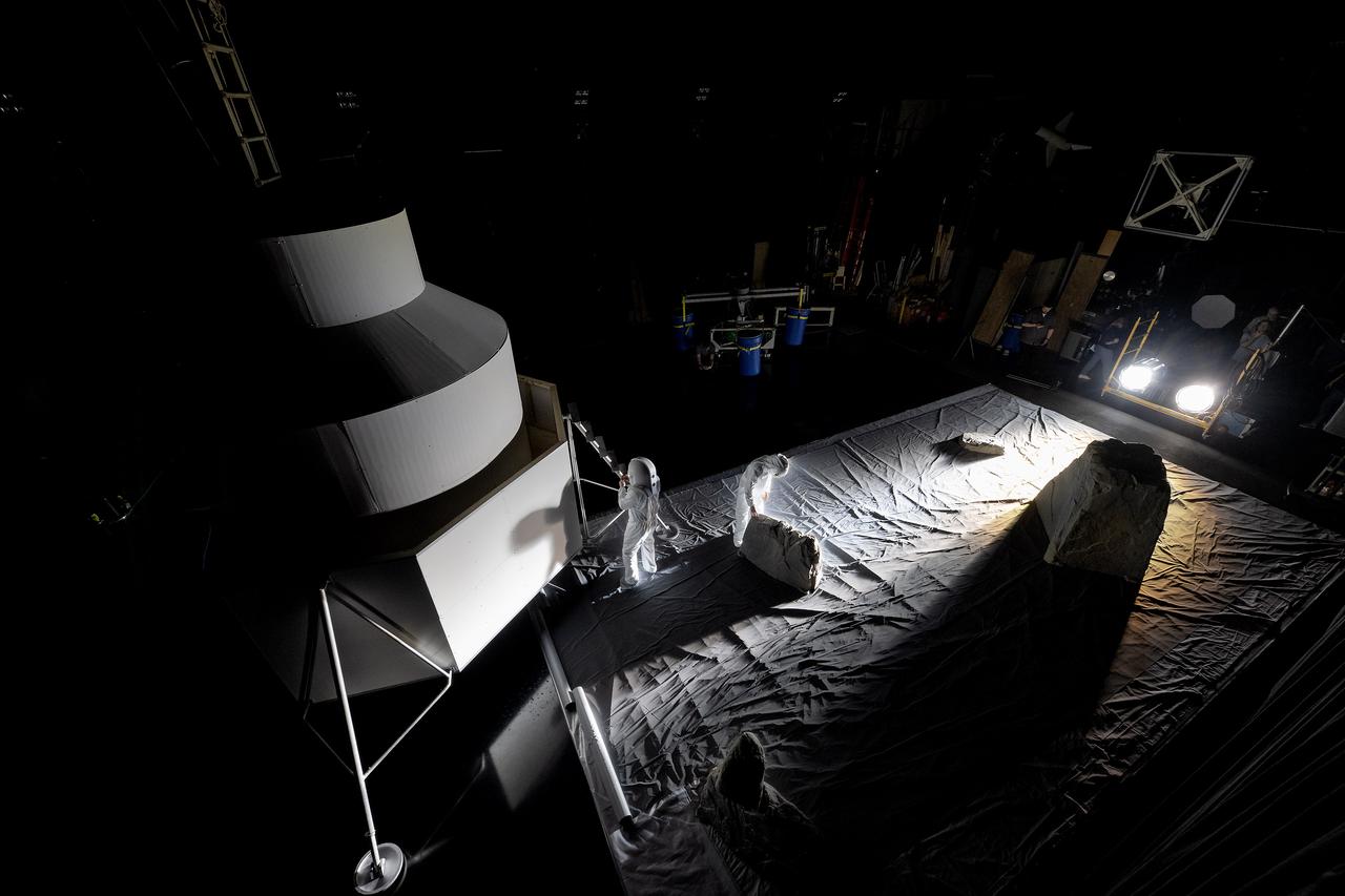
These photos show how teams at NASA’s Marshall Space Flight Center in Huntsville, Alabama, are using the Flat Floor Facility (Building 4619) to understand the lunar lighting environment in preparation for the Artemis III crewed lunar landing mission, slated for 2027. The Flat Floor Facility is an air-bearing floor, providing full-scale simulation capabilities for lunar surface systems by simulating zero gravity in two dimensions. Wearing low-fidelity materials, test engineers can understand how the extreme lighting of the Moon’s South Pole could affect surface operations during Artemis III. High-intensity lights are positioned at a low angle to replicate the strong shadows that are cast across the lunar South Pole by the Sun. Data and analysis from testing at NASA Marshall are improving models Artemis astronauts will use in preparation for lander and surface operations on the Moon during Artemis III. Testing in the facility is also helping cross-agency teams evaluate various tools astronauts may use. NASA Marshall manages the Human Landing System (HLS) Program. For more information, contact NASA Marshall’s Office of Communications at 256-544-0034.
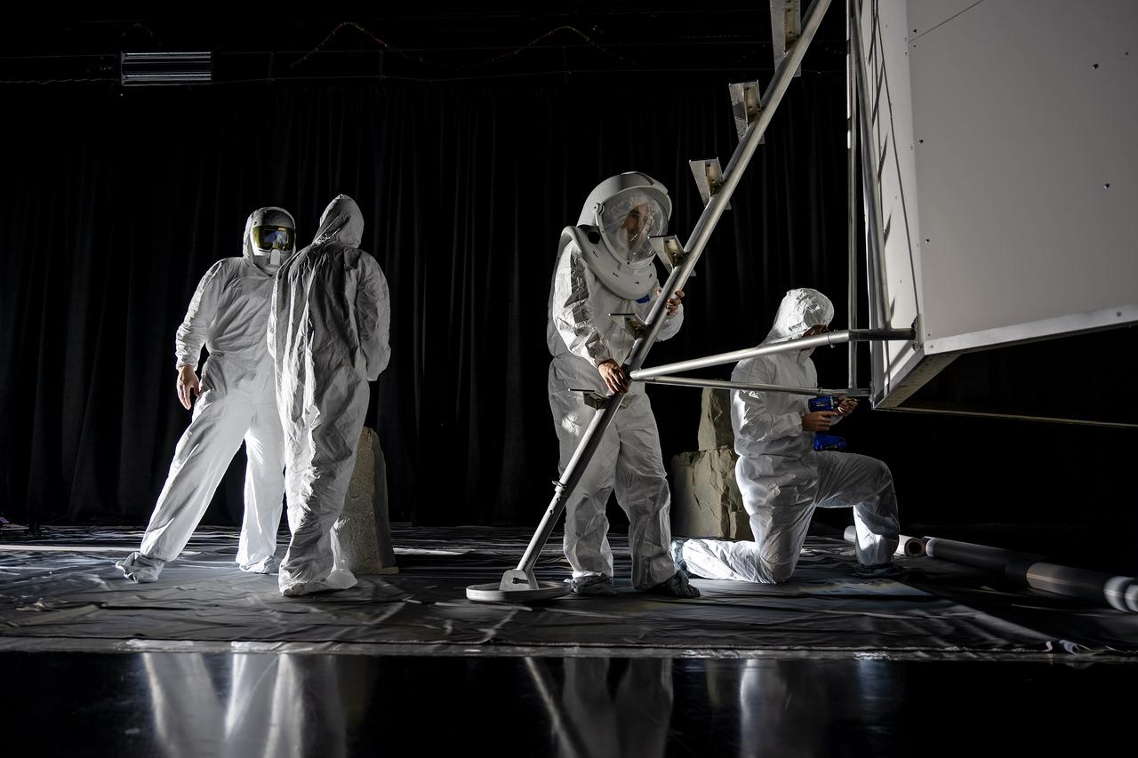
These photos show how teams at NASA’s Marshall Space Flight Center in Huntsville, Alabama, are using the Flat Floor Facility (Building 4619) to understand the lunar lighting environment in preparation for the Artemis III crewed lunar landing mission, slated for 2027. The Flat Floor Facility is an air-bearing floor, providing full-scale simulation capabilities for lunar surface systems by simulating zero gravity in two dimensions. Wearing low-fidelity materials, test engineers can understand how the extreme lighting of the Moon’s South Pole could affect surface operations during Artemis III. High-intensity lights are positioned at a low angle to replicate the strong shadows that are cast across the lunar South Pole by the Sun. Data and analysis from testing at NASA Marshall are improving models Artemis astronauts will use in preparation for lander and surface operations on the Moon during Artemis III. Testing in the facility is also helping cross-agency teams evaluate various tools astronauts may use. NASA Marshall manages the Human Landing System (HLS) Program. For more information, contact NASA Marshall’s Office of Communications at 256-544-0034.
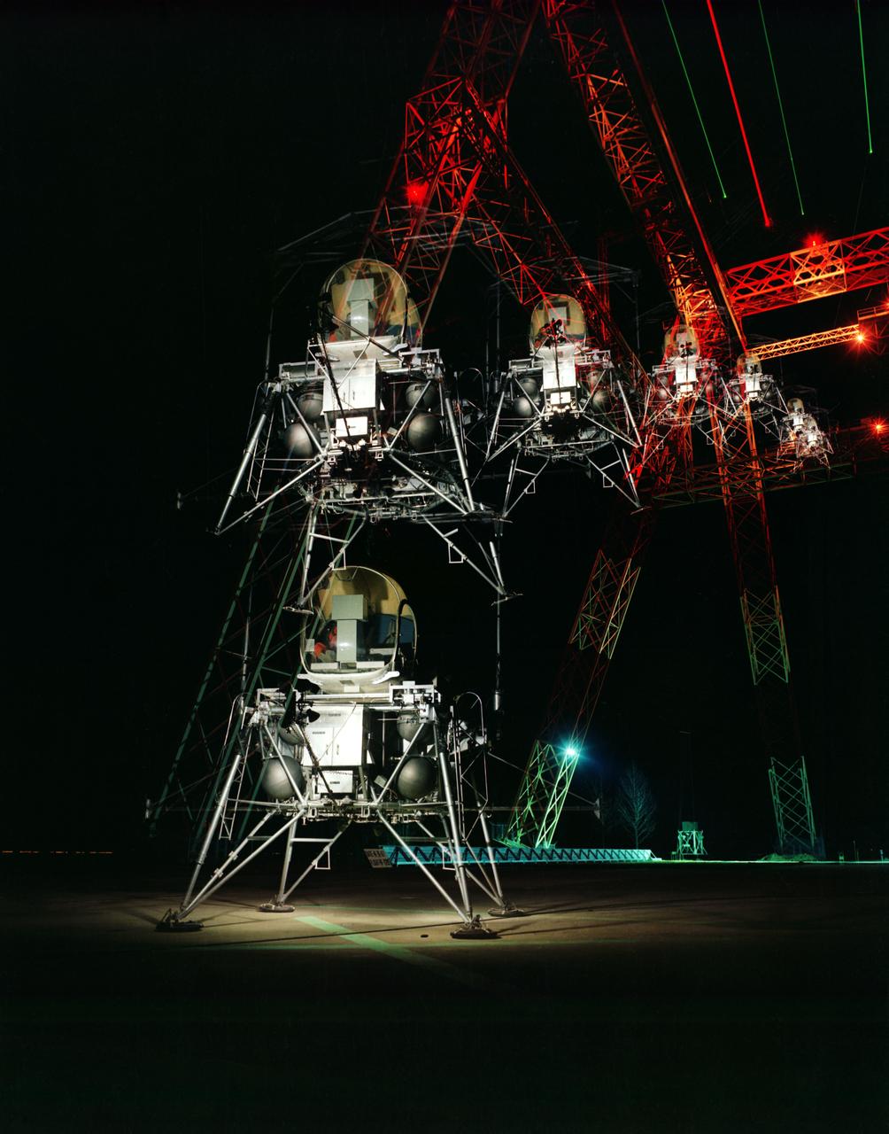
During a nighttime training session, a multiple exposure captures the movement of the Lunar Excursion Module Simulator (LEMS). The LEMS was a manned vehicle used to familiarize the Apollo astronauts with the handling characteristics of lunar-landing type vehicle. The Apollo Program is best known for the astronaut Neal Armstrong s first step on the Moon July 20, 1969. In its earliest test period, the LEMS featured a helicopter crew cabin atop the lunar landing module. Later, the helicopter crew cabin was replaced with a stand-up rectangular cabin which was more efficient for controlling maneuvers and for better viewing by the pilot. The vehicle was designed at Langley Research Center in Hampton, VA. This multiple exposure shows a simulated Moon landing of the (LEMS) trainer at Langley s Lunar Landing Research Facility. -- Photograph published in Winds of Change, 75th Anniversary NASA publication (page 70), by James Shultz. Also published in " A Century at Langley" by Joseph Chambers, pg. 93.
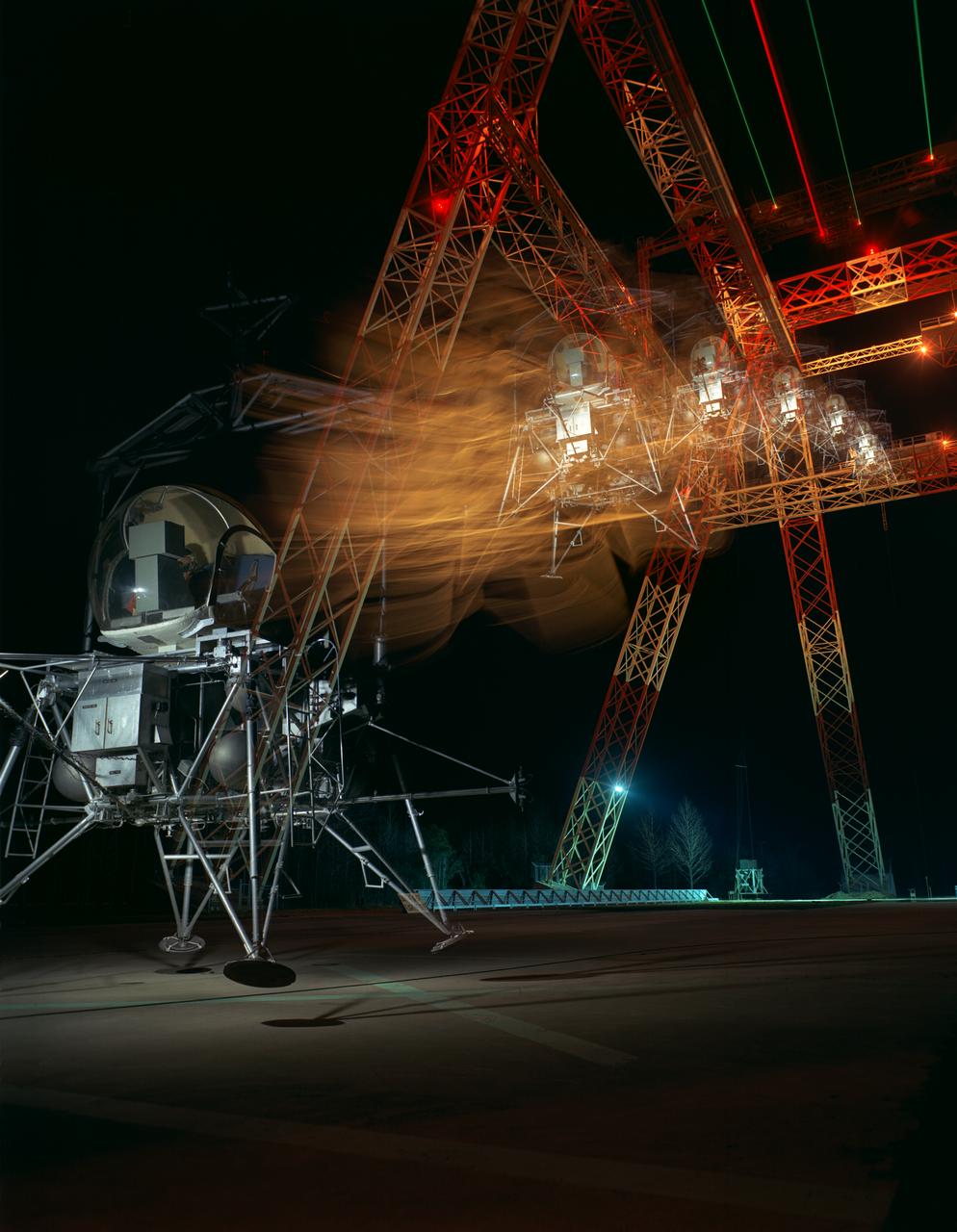
During a nighttime training session, a multiple exposure captures the movement of the Lunar Excursion Module Simulator (LEMS). The LEMS was a manned vehicle used to familiarize the Apollo astronauts with the handling characteristics of lunar-landing type vehicle. The Apollo Program is best known for the astronaut Neal Armstrong s first step on the Moon July 20, 1969. In its earliest test period, the LEMS featured a helicopter crew cabin atop the lunar landing module. Later, the helicopter crew cabin was replaced with a stand-up rectangular cabin which was more efficient for controlling maneuvers and for better viewing by the pilot. The vehicle was designed at Langley Research Center in Hampton, VA. This multiple exposure shows a simulated Moon landing of the (LEMS) trainer at Langley s Lunar Landing Research Facility. -- Photograph published in Winds of Change, 75th Anniversary NASA publication (page 70), by James Shultz. Also published in " A Century at Langley" by Joseph Chambers, pg. 93.
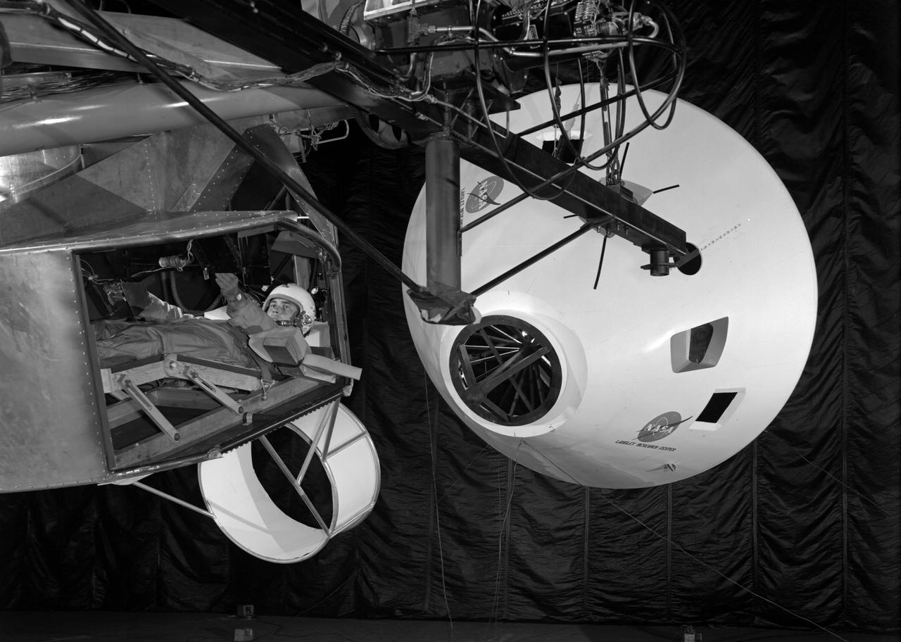
Originally the Rendezvous was used by the astronauts preparing for Gemini missions. The Rendezvous Docking Simulator was then modified and used to develop docking techniques for the Apollo program. The pilot is shown maneuvering the LEM into position for docking with a full-scale Apollo Command Module. From A.W. Vogeley, Piloted Space-Flight Simulation at Langley Research Center, Paper presented at the American Society of Mechanical Engineers, 1966 Winter Meeting, New York, NY, November 27 - December 1, 1966. The Rendezvous Docking Simulator and also the Lunar Landing Research Facility are both rather large moving-base simulators. It should be noted, however, that neither was built primarily because of its motion characteristics. The main reason they were built was to provide a realistic visual scene. A secondary reason was that they would provide correct angular motion cues (important in control of vehicle short-period motions) even though the linear acceleration cues would be incorrect. Apollo Rendezvous Docking Simulator: Langley s Rendezvous Docking Simulator was developed by NASA scientists to study the complex task of docking the Lunar Excursion Module with the Command Module in Lunar orbit.
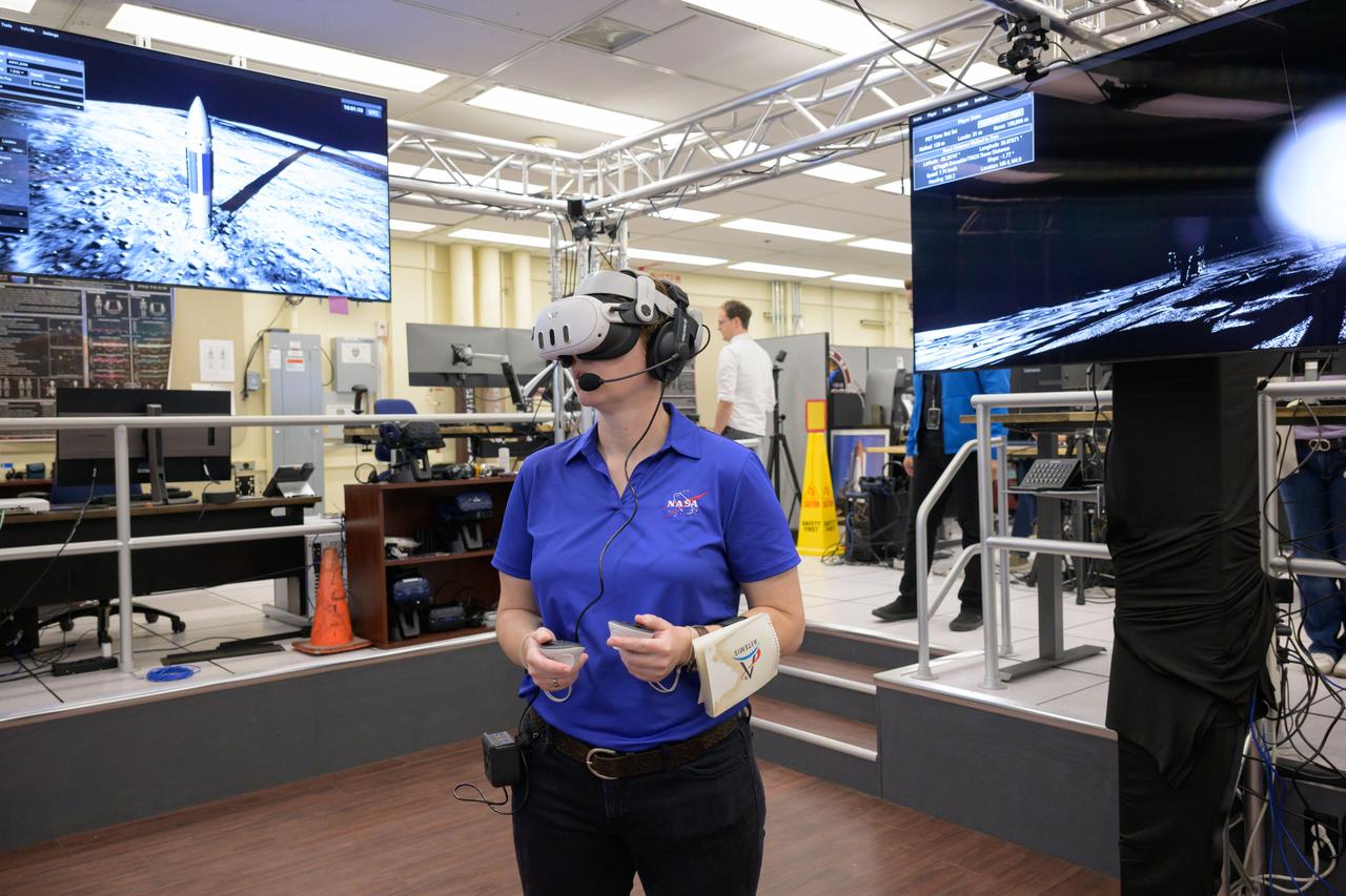
jsc2024e076628 – Tess Caswell, a crew stand-in for the Artemis III Virtual Reality Mini-Simulation, executes a moonwalk in the Prototype Immersive Technology (PIT) lab at NASA’s Johnson Space Center in Houston. The simulation was a test of using VR as a training method for flight controllers and science teams’ collaboration on science-focused traverses on the lunar surface. Credit: NASA/Robert Markowitz
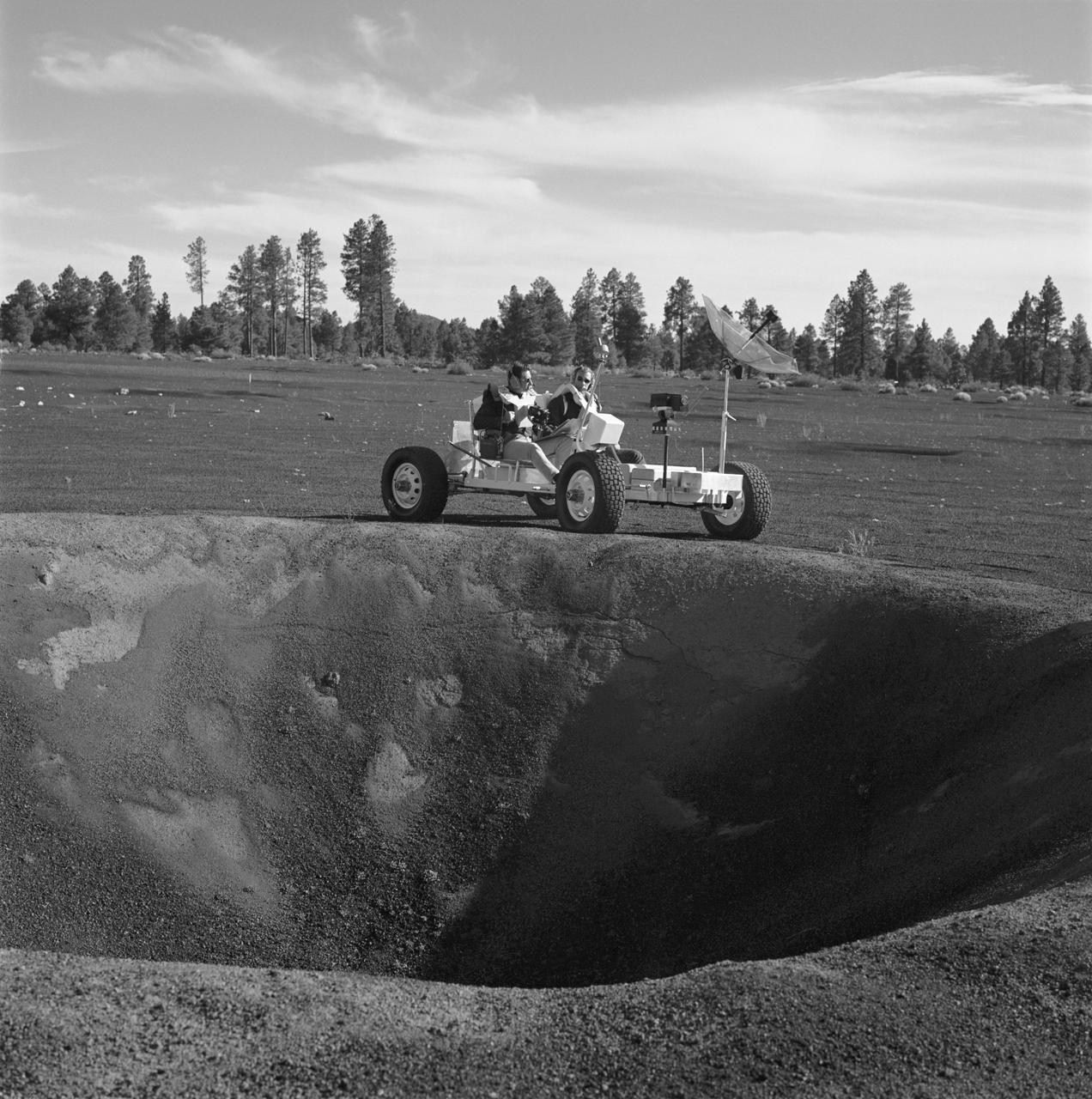
S70-53300 (2-3 Nov. 1970) --- Two Apollo 15 crew members, riding a Lunar Roving Vehicle (LRV) simulator, participate in geology training at the Cinder Lake crater field in Arizona. Astronaut David R. Scott, Apollo 15 commander, seated on the left; and to Scott's right is astronaut James B. Irwin, lunar module pilot. They have stopped at the rim of a 30-feet deep crater to look over the terrain. The simulator, called "Grover", was built by the United States Geological Survey.
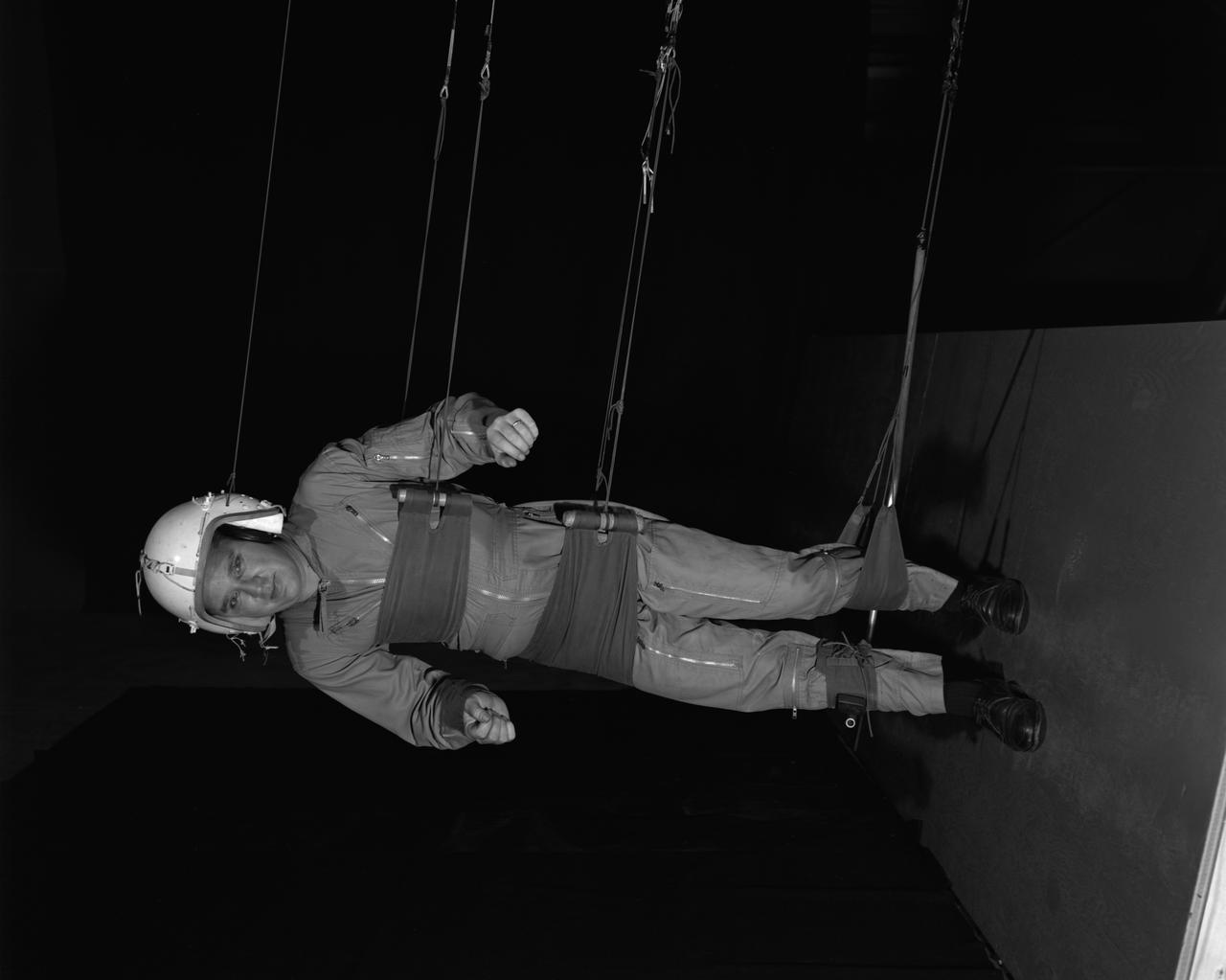
Reduced Gravity Walking Simulator located in the hangar at Langley Research Center. The initial version of this simulator was located inside the hangar. Later a larger version would be located at the Lunar Landing Facility. The purpose of this simulator was to study the subject while walking, jumping or running. Researchers conducted studies of various factors such as fatigue limit, energy expenditure, and speed of locomotion. A.W. Vigil wrote in his paper Discussion of Existing and Planned Simulators for Space Research, When the astronauts land on the moon they will be in an unfamiliar environment involving, particularly, a gravitational field only one-sixth as strong as on earth. A novel method of simulating lunar gravity has been developed and is supported by a puppet-type suspension system at the end of a long pendulum. A floor is provided at the proper angle so that one-sixth of the subject' s weight is supported by the floor with the remainder being supported by the suspension system. This simulator allows almost complete freedom in vertical translation and pitch and is considered to be a very realistic simulation of the lunar walking problem. For this problem this simulator suffers only slightly from the restrictions in lateral movement it puts on the test subject. This is not considered a strong disadvantage for ordinary walking problems since most of the motions do, in fact, occur in the vertical plane. However, this simulation technique would be severely restrictive if applied to the study of the extra-vehicular locomotion problem, for example, because in this situation complete six degrees of freedom are rather necessary. This technique, in effect, automatically introduces a two-axis attitude stabilization system into the problem. The technique could, however, be used in preliminary studies of extra-vehicular locomotion where, for example, it might be assumed that one axis of the attitude control system on the astronaut maneuvering unit may have failed. -- Published in James R. Hansen, Spaceflight Revolution: NASA Langley Research Center From Sputnik to Apollo, NASA SP-4308, p. 377 A.W. Vigil, Discussion of Existing and Planned Simulators for Space Research, Paper presented at Conference on the Role of Simulation in Space Technology, Blacksburg, VA, August 17-21, 1964.
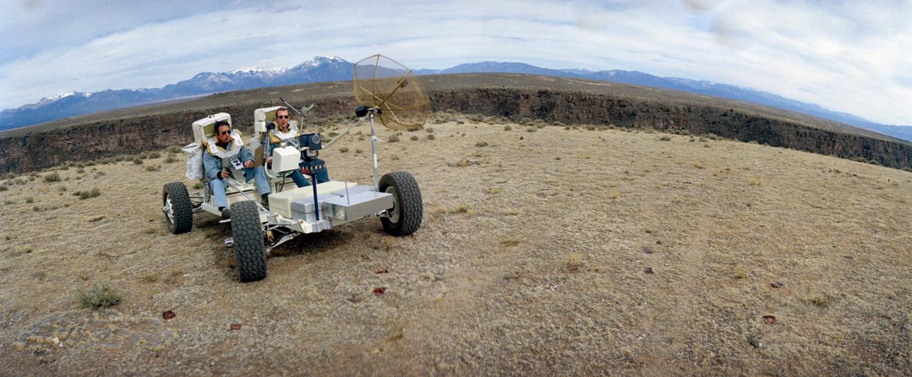
S71-23774 (11-12 March 1971) --- A wide-angle view showing two members of the prime crew of the Apollo 15 lunar landing mission riding in a Lunar Roving Vehicle trainer called "Grover" during a simulation of lunar surface extravehicular activity in the Taos, New Mexico area. They are astronauts David R. Scott (riding in left side seat), commander; and James B. Irwin, lunar module pilot. Apollo 15 will be the first mission to the moon to carry a Lunar Roving Vehicle, which will permit the astronauts to cover a larger area for exploration and sample collecting than on previous missions.
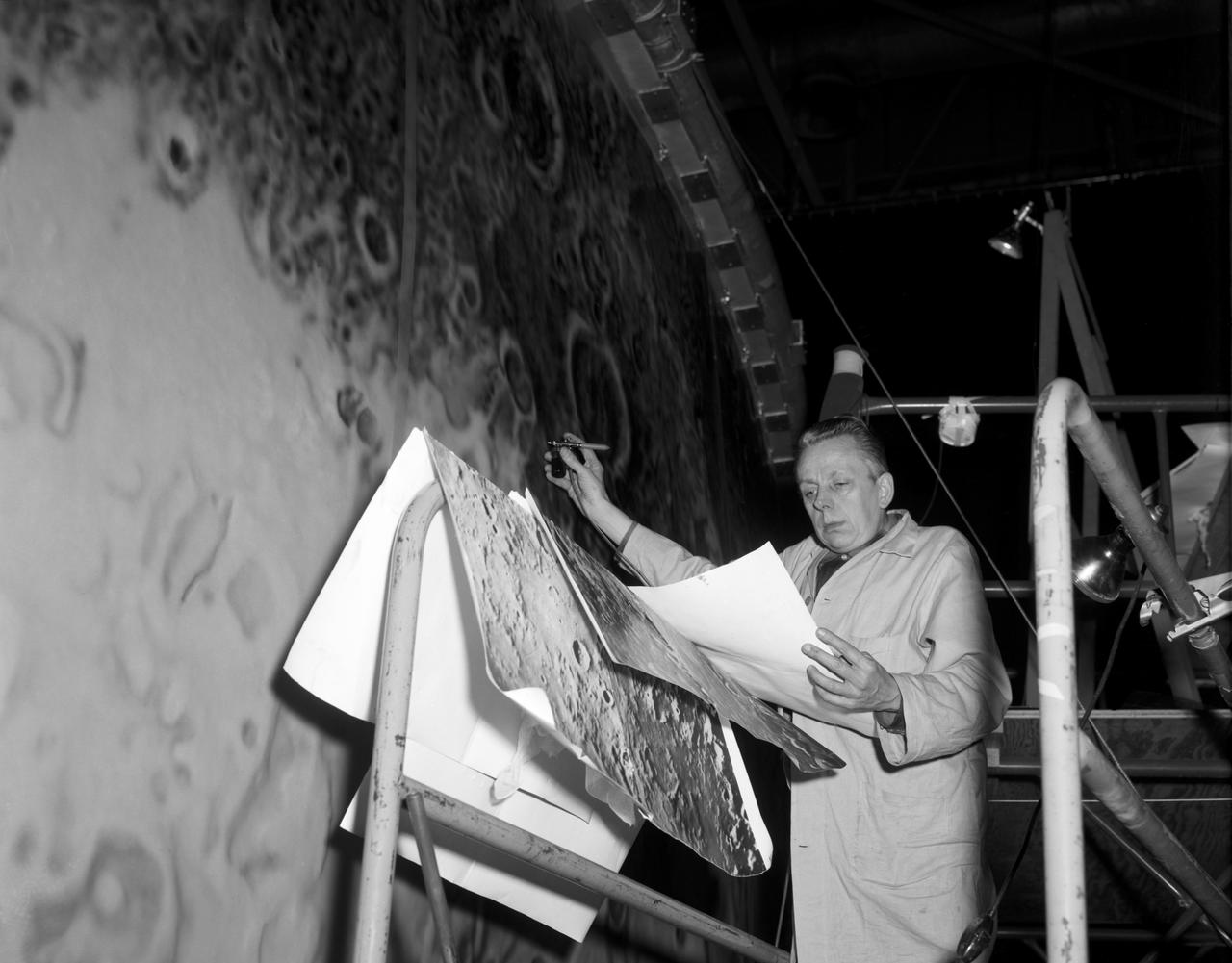
Artists used paintbrushes and airbrushes to recreate the lunar surface on each of the four models comprising the LOLA simulator. Project LOLA or Lunar Orbit and Landing Approach was a simulator built at Langley to study problems related to landing on the lunar surface. It was a complex project that cost nearly $2 million dollars. James Hansen wrote: "This simulator was designed to provide a pilot with a detailed visual encounter with the lunar surface; the machine consisted primarily of a cockpit, a closed-circuit TV system, and four large murals or scale models representing portions of the lunar surface as seen from various altitudes. The pilot in the cockpit moved along a track past these murals which would accustom him to the visual cues for controlling a spacecraft in the vicinity of the moon. Unfortunately, such a simulation--although great fun and quite aesthetic--was not helpful because flight in lunar orbit posed no special problems other than the rendezvous with the LEM, which the device did not simulate. Not long after the end of Apollo, the expensive machine was dismantled." (p. 379) Ellis J. White further described LOLA in his paper "Discussion of Three Typical Langley Research Center Simulation Programs," "Model 1 is a 20-foot-diameter sphere mounted on a rotating base and is scaled 1 in. = 9 miles. Models 2,3, and 4 are approximately 15x40 feet scaled sections of model 1. Model 4 is a scaled-up section of the Crater Alphonsus and the scale is 1 in. = 200 feet. All models are in full relief except the sphere." -- Published in James R. Hansen, Spaceflight Revolution, NASA SP-4308, p. 379; Ellis J. White, "Discussion of Three Typical Langley Research Center Simulation Programs," Paper presented at the Eastern Simulation Council (EAI's Princeton Computation Center), Princeton, NJ, October 20, 1966.
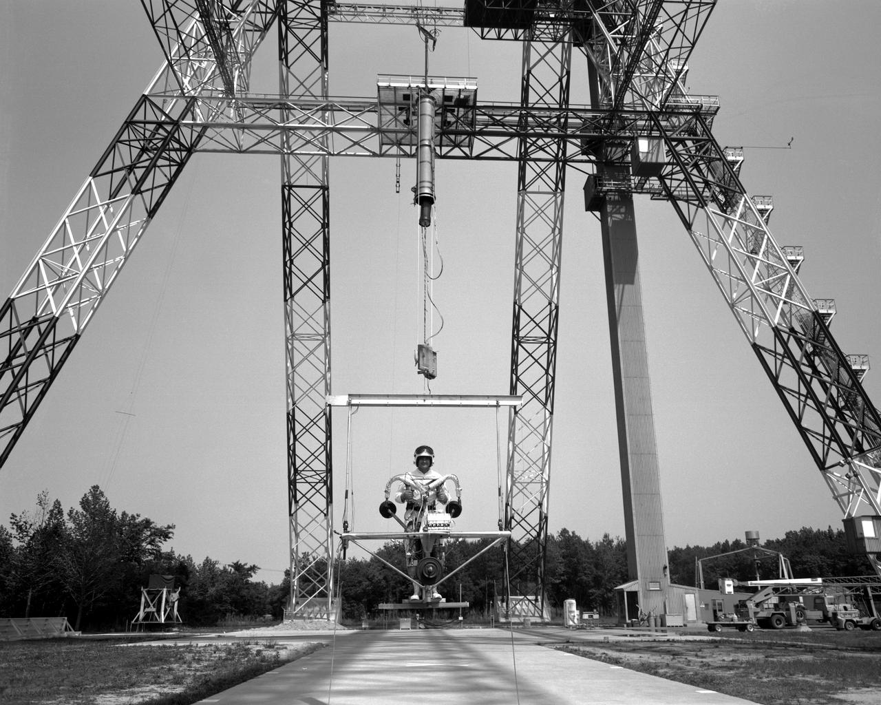
POGO is a device that uses cables connected to the ceiling to suspend an astronaut. POGO supports five-sixths of a person's weight; it mimics the one-sixth gravity of the moon. An astronaut walking around on POGO has the sensation of walking on the moon. POGO has been around since the Apollo days - in fact, the device gets its name from the way Apollo astronauts tended to bounce when suspended from it. The real name for POGO is the Partial Gravity Simulator.
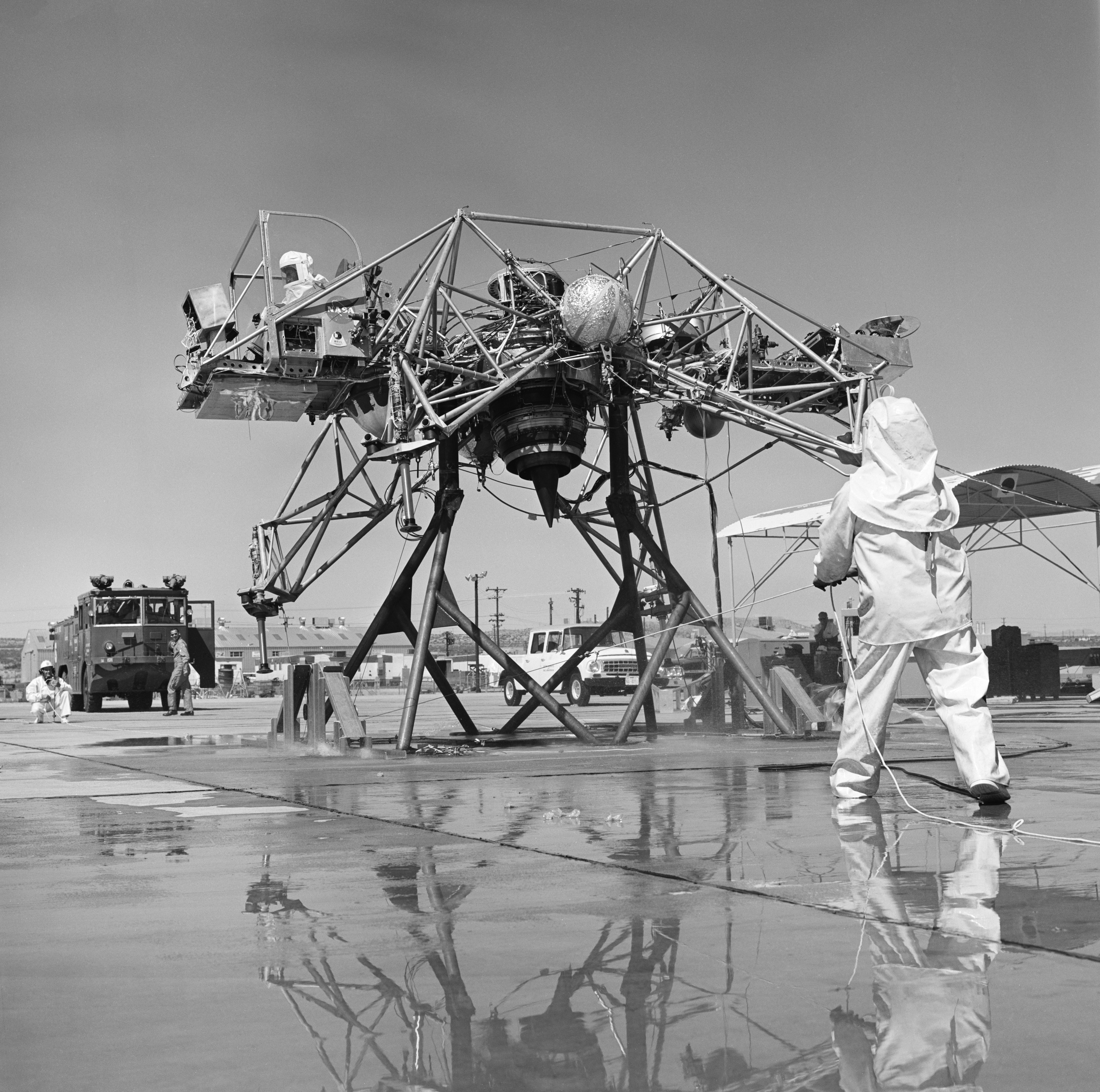
Mechanics are dressed in fire suits because the Lunar Landing Research Vehicle, a simulator to train astronauts for a moon landing, had 90% pure hydrogen peroxide thrusters.
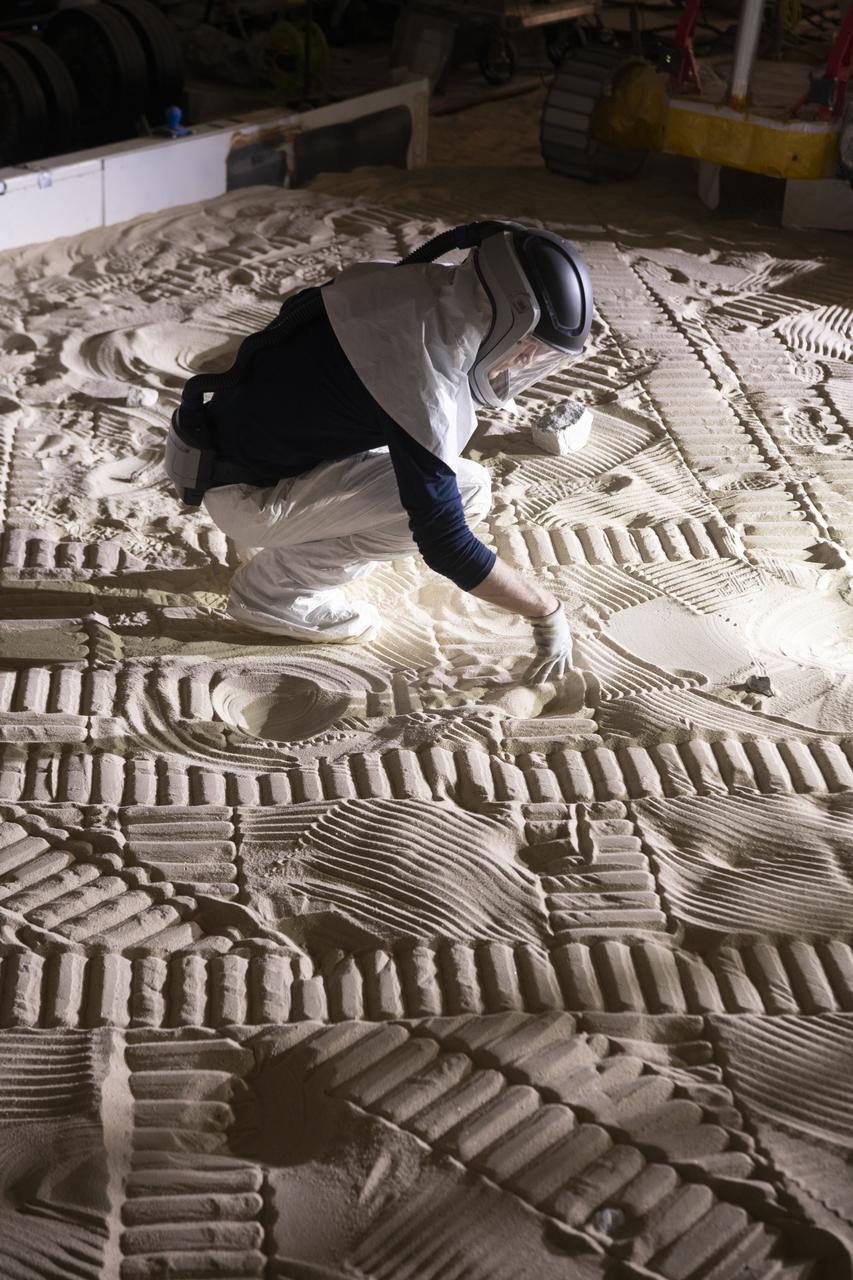
An Engineer maps out the position of rocks during VIPER testing at The NASA Glenn Research Center. A test version of the VIPER rover continues to show how well it moves through a simulated lunar surface in our SLOPE lab. This is a critical step toward ensuring the rover is ready for its 2023 mission to find water ice at the Moon’s South pole.
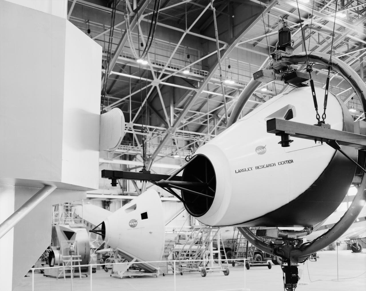
Originally the Rendezvous was used by the astronauts preparing for Gemini missions. The Rendezvous Docking Simulator was then modified and used to develop docking techniques for the Apollo program. This picture shows a later configuration of the Apollo docking with the LEM target. A.W. Vogeley described the simulator as follows: The Rendezvous Docking Simulator and also the Lunar Landing Research Facility are both rather large moving-base simulators. It should be noted, however, that neither was built primarily because of its motion characteristics. The main reason they were built was to provide a realistic visual scene. A secondary reason was that they would provide correct angular motion cues (important in control of vehicle short-period motions) even though the linear acceleration cues would be incorrect. -- Published in A.W. Vogeley, Piloted Space-Flight Simulation at Langley Research Center, Paper presented at the American Society of Mechanical Engineers, 1966 Winter Meeting, New York, NY, November 27 - December 1, 1966.
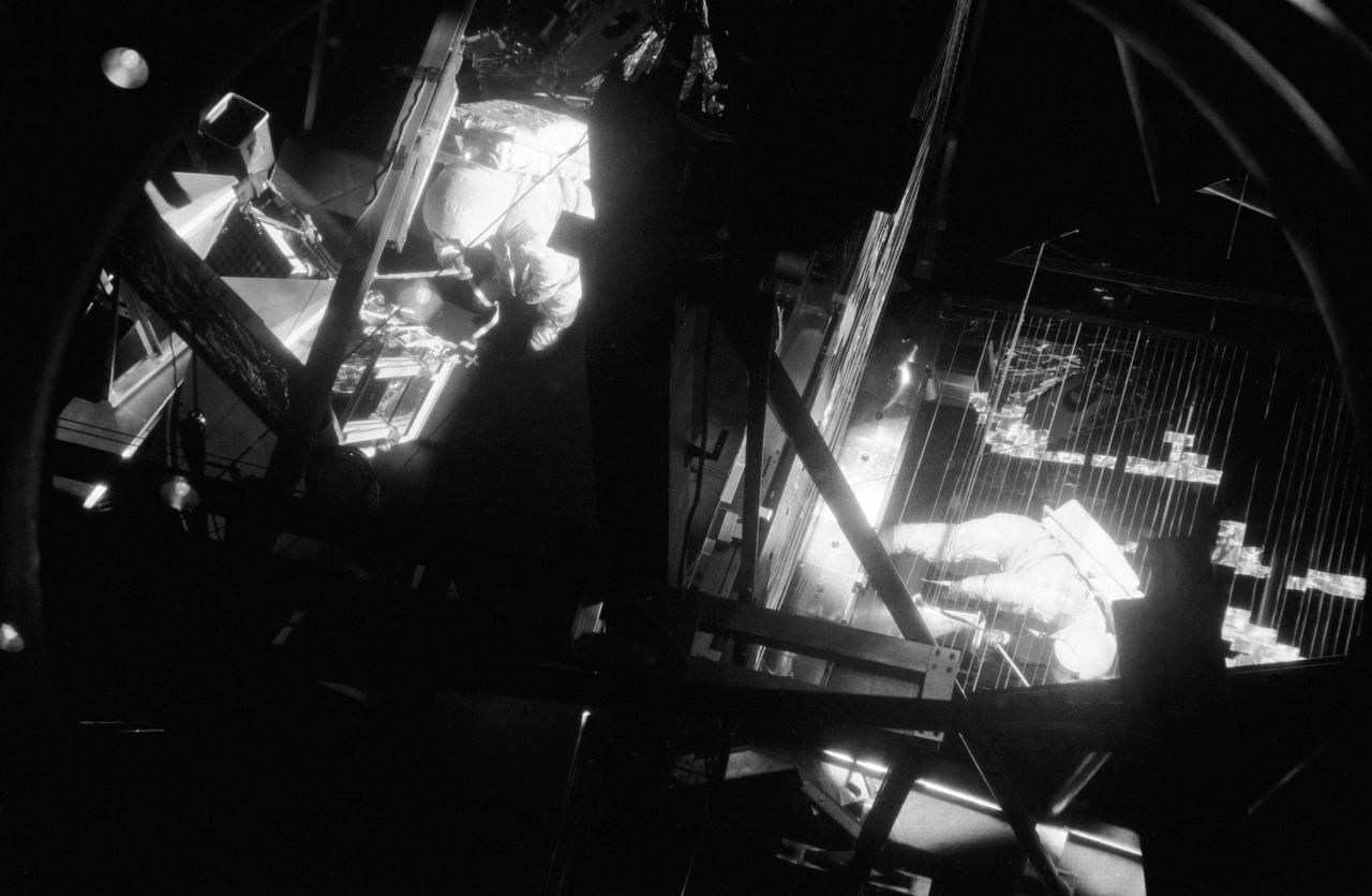
Astronaut Neil A. Armstrong, commander of the Apollo 11 lunar landing mission, is photographed during thermovacuum training in Chamber B of the Space Environment Simulation Laboratory, Building 32, Manned Spacecraft Center. He is wearing an Extravehicular Mobility Unit. The training simulated lunar surface vacuum and thermal conditions during astronaut operations outside the Lunar Module on the moon's surface. The mirror was used to reflect solar light.
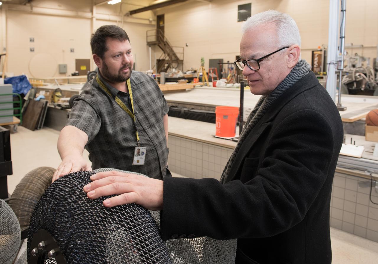
A Co-inventor of the Shape Memory Alloy, Spring Tire, shows the NASA Chief Technologist the first SMA Spring Tire Prototype during a tour of the Glenn Research Center, Simulated Lunar Operations Laboratory (SLOPE).

Project LOLA. Test subject sitting at the controls: Project LOLA or Lunar Orbit and Landing Approach was a simulator built at Langley to study problems related to landing on the lunar surface. It was a complex project that cost nearly 2 million dollars. James Hansen wrote: This simulator was designed to provide a pilot with a detailed visual encounter with the lunar surface the machine consisted primarily of a cockpit, a closed-circuit TV system, and four large murals or scale models representing portions of the lunar surface as seen from various altitudes. The pilot in the cockpit moved along a track past these murals which would accustom him to the visual cues for controlling a spacecraft in the vicinity of the moon. Unfortunately, such a simulation--although great fun and quite aesthetic--was not helpful because flight in lunar orbit posed no special problems other than the rendezvous with the LEM, which the device did not simulate. Not long after the end of Apollo, the expensive machine was dismantled. (p. 379) Ellis J. White wrote in his paper, Discussion of Three Typical Langley Research Center Simulation Programs : A typical mission would start with the first cart positioned on model 1 for the translunar approach and orbit establishment. After starting the descent, the second cart is readied on model 2 and, at the proper time, when superposition occurs, the pilot s scene is switched from model 1 to model 2. then cart 1 is moved to and readied on model 3. The procedure continues until an altitude of 150 feet is obtained. The cabin of the LM vehicle has four windows which represent a 45 degree field of view. The projection screens in front of each window represent 65 degrees which allows limited head motion before the edges of the display can be seen. The lunar scene is presented to the pilot by rear projection on the screens with four Schmidt television projectors. The attitude orientation of the vehicle is represented by changing the lunar scene through the portholes determined by the scan pattern of four orthicons. The stars are front projected onto the upper three screens with a four-axis starfield generation (starball) mounted over the cabin and there is a separate starball for the low window. -- Published in James R. Hansen, Spaceflight Revolution: NASA Langley Research Center From Sputnik to Apollo, (Washington: NASA, 1995), p. 379 Ellis J. White, Discussion of Three Typical Langley Research Center Simulation Programs, Paper presented at the Eastern Simulation Council (EAI s Princeton Computation Center), Princeton, NJ, October 20, 1966.
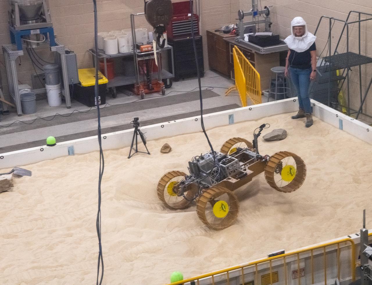
Volatiles Investigating Polar Exploration Rover, VIPER Testing in the Simulated Lunar Operations Lab, SLOPE Laboratory
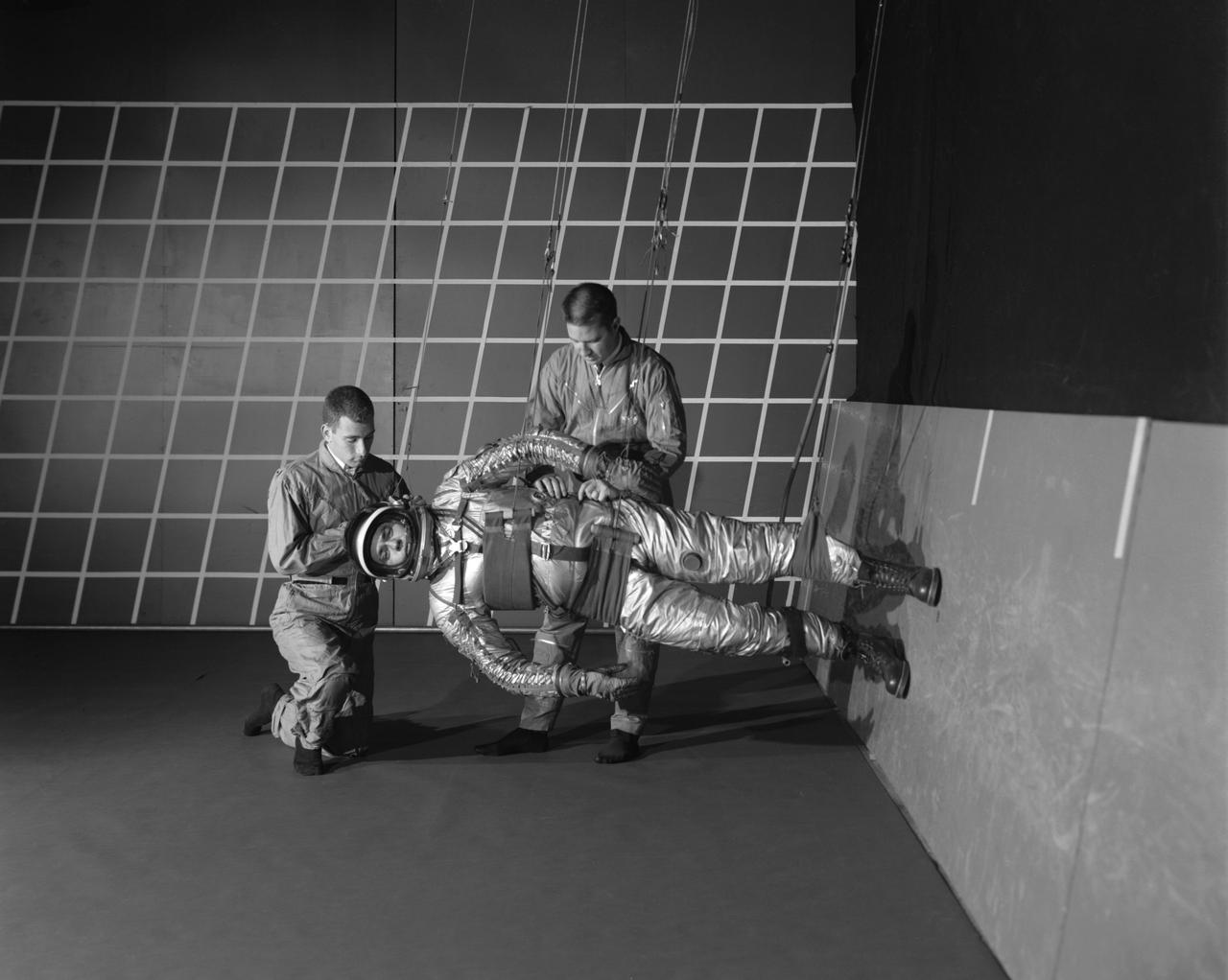
A test subject being suited up for studies on the Reduced Gravity Walking Simulator located in the hangar at Langley Research Center. The initial version of this simulator was located inside the hangar. Later a larger version would be located at the Lunar Landing Facility. The purpose of this simulator was to study the subject while walking, jumping or running. Researchers conducted studies of various factors such as fatigue limit, energy expenditure, and speed of locomotion. Francis B. Smith wrote in his paper "Simulators For Manned Space Research," "I would like to conclude this talk with a discussion of a device for simulating lunar gravity which is very effective and yet which is so simple that its cost is in the order of a few thousand dollars at most, rather than hundreds of thousands. With a little ingenuity, one could almost build this type simulator in his backyard for children to play on. The principle is ...if a test subject is suspended in a sling so that his body axis makes an angle of 9 1/2 degrees with the horizontal and if he then "stands" on a platform perpendicular to his body axis, the component of the earth's gravity forcing him toward the platform is one times the sine of 9 1/2 degrees or approximately 1/6 of the earth's normal gravity field. That is, a 180 pound astronaut "standing" on the platform would exert a force of only 30 pounds - the same as if he were standing upright on the lunar surface." -- Published in James R. Hansen, Spaceflight Revolution: NASA Langley Research Center From Sputnik to Apollo, NASA SP-4308; Francis B. Smith, "Simulators For Manned Space Research," Paper for 1966 IEEE International Convention, New York, NY, March 21-25, 1966
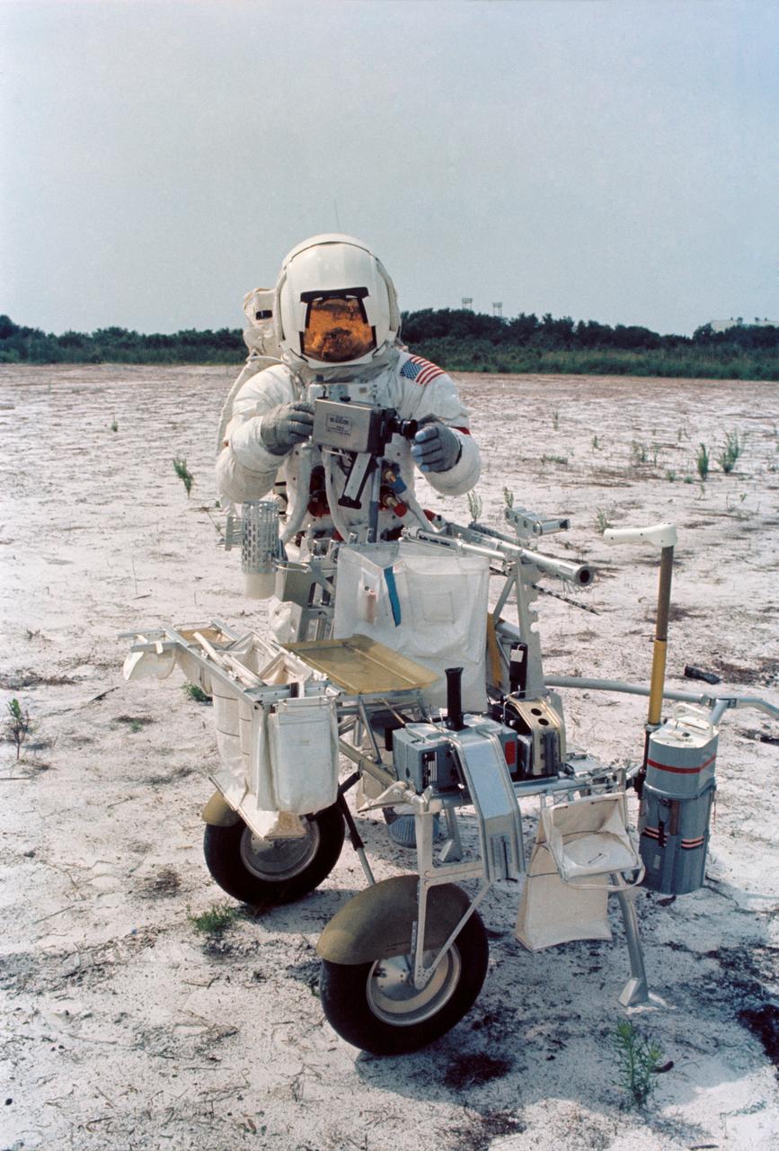
S70-46191 (July 1970) --- Astronaut Alan B. Shepard Jr., commander of the Apollo 14 lunar landing mission, participates in lunar surface training at the Kennedy Space Center (KSC). Shepard is adjusting a camera mounted to the modular equipment transporter (MET). The MET, nicknamed the "Rickshaw", will serve as a portable work bench with a place for the Apollo lunar hand tools and their carrier, three cameras, two sample container bags, a special environment sample container, spare magazines, and a lunar surface Penetrometer. Shepard is wearing an Extravehicular Mobility Unit (EMU).
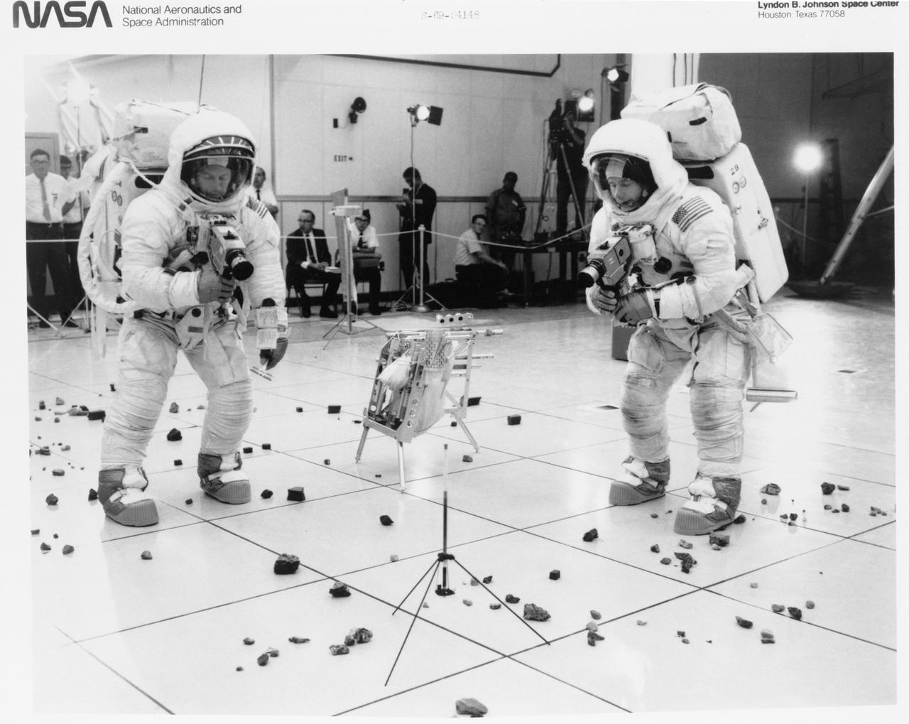
S69-54148 (October 1969) --- Two members of the Apollo 12 lunar landing mission participates in lunar surface extravehicular activity (EVA) simulations in the Kennedy Space Center's (KSC) Flight Crew Training Building. Here, astronauts Charles Conrad Jr. (on left), commander, and Alan L. Bean, lunar module pilot, simulate the photographic documentation of lunar rock samples. The simulations were part of a run-through of the Apollo 12 lunar surface "timeline".
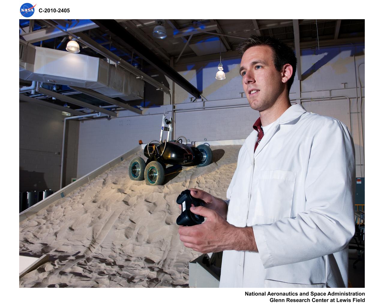
Simulated Lunar Operations Laboratory (SLOPE) Lab; Scarab Lunar Rover
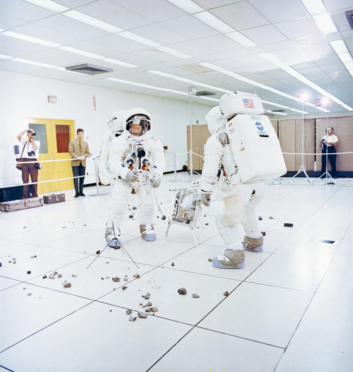
S69-55368 (6 Oct. 1969) --- Two members of the Apollo 12 lunar landing mission participate in lunar surface extravehicular activity (EVA) simulations in the Flight Crew Training Building at the Kennedy Space Center (KSC). Astronaut Charles Conrad Jr., commander (facing camera), simulates picking up samples. Astronaut Alan L. Bean, lunar module pilot, simulates photographic lunar rock sample documentation.
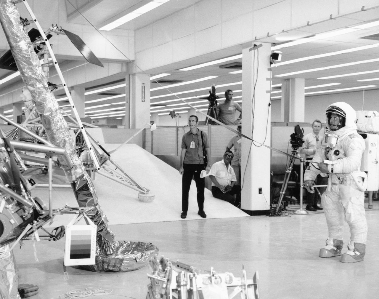
S69-54147 (October 1969) --- Two members of the Apollo 12 lunar landing mission participates in lunar surface extravehicular activity (EVA) simulations in the Kennedy Space Center's (KSC) Flight Crew Training Building. Here, astronauts Charles Conrad Jr., commander, is holding the bottom end of the lunar equipment conveyor. Inside the Lunar Module (LM) and out of view is astronaut Alan L. Bean, lunar module pilot. The simulations were part of a run-through of the Apollo 12 lunar surface "timeline".

Simulated Lunar Operations Facility, SLOPE
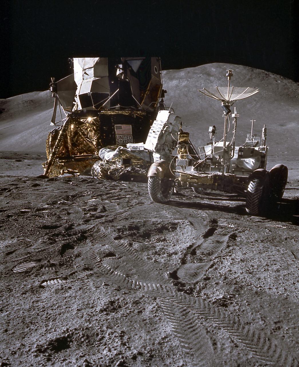
This photograph of an astronaut getting the Lunar Roving Vehicle (LRV) ready for exploration of the lunar surface was taken during activities of the Apollo 15 mission. Designed and developed by the Marshall Space Flight Center and built by the Boeing Company, the LRV was first used on the Apollo 15 mission and increased the range of astronauts' mobility and productivity on the lunar surface.
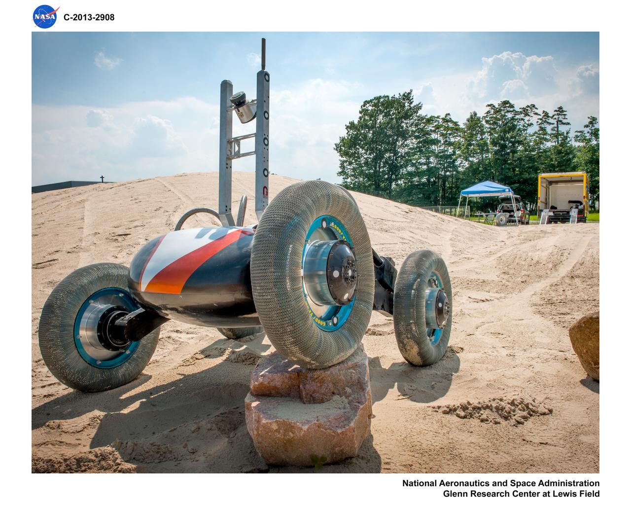
Photos of test hardware, Scarab Lunar Exploration Rover at the DUNE, outdoor Simulated Lunar Operations Laboratory, SLOPE
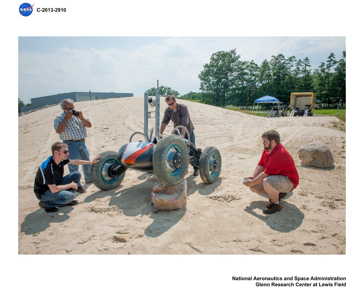
Photos of test hardware, Scarab Lunar Exploration Rover at the DUNE, outdoor Simulated Lunar Operations Laboratory, SLOPE

Views of Astronaut Dr. Philip K. Chapman training in the Lunar Module (LM) Simulator, Centrifuge, and the Apollo Mission Simulator. MSC
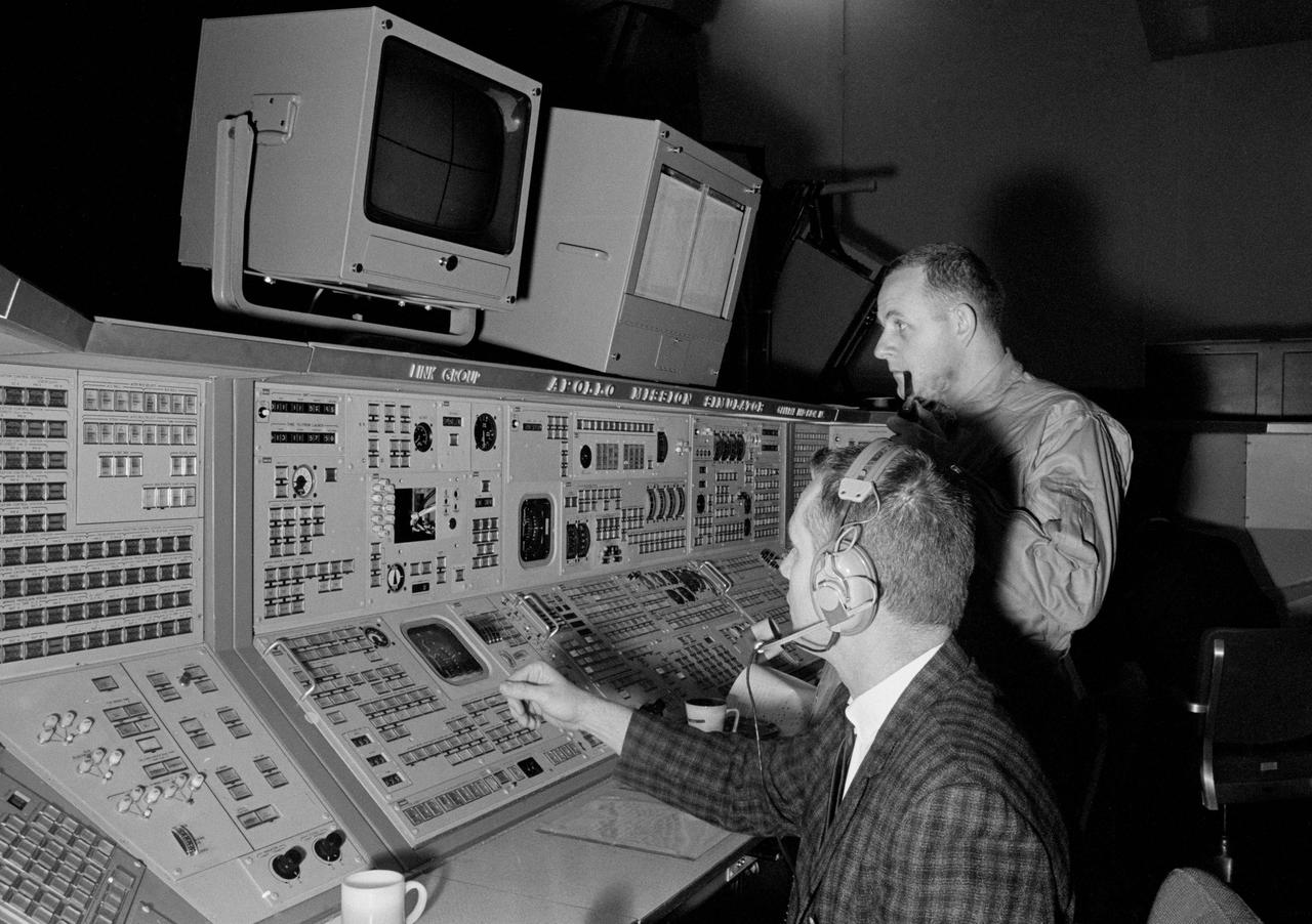
Views of Astronaut Dr. Philip K. Chapman training in the Lunar Module (LM) Simulator, Centrifuge, and the Apollo Mission Simulator. MSC
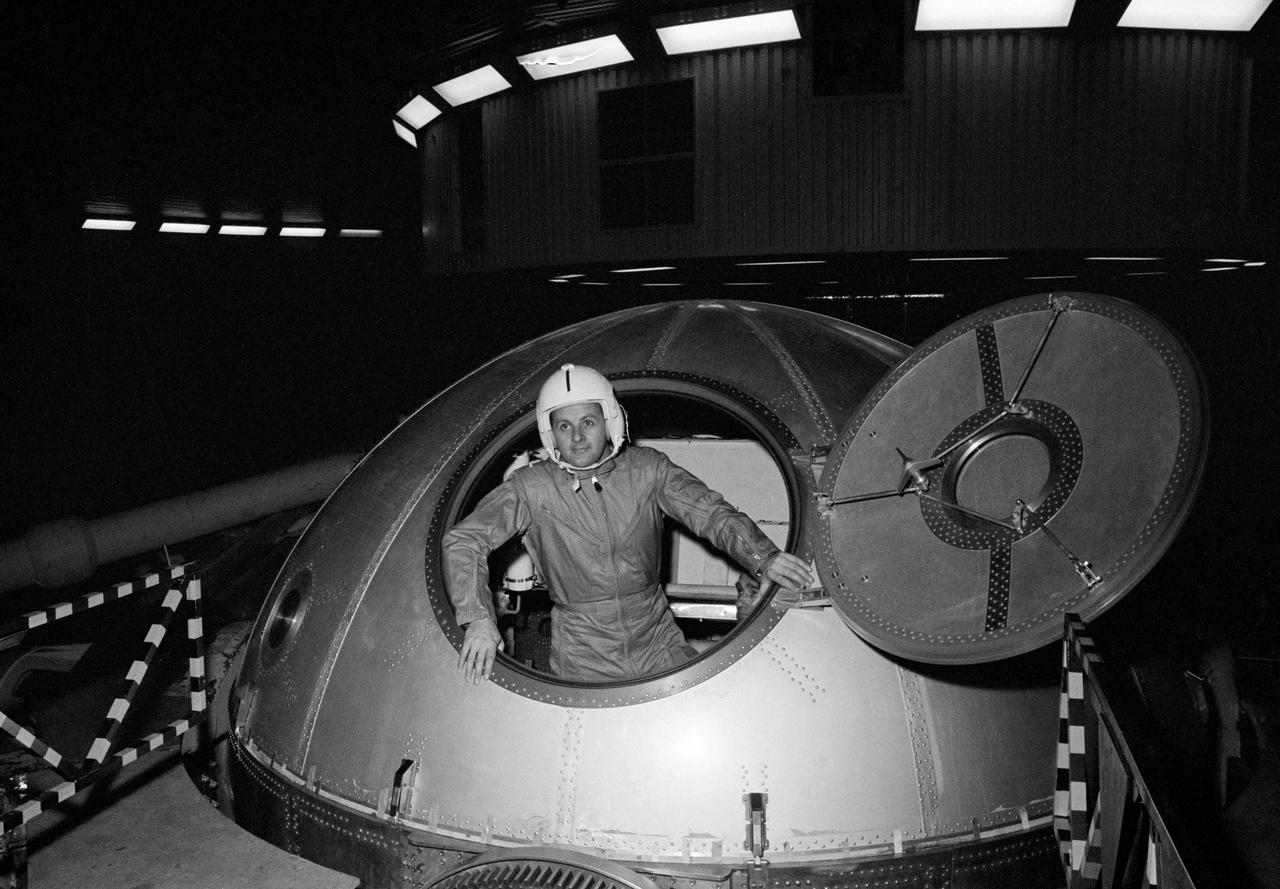
Views of Astronaut Dr. Philip K. Chapman training in the Lunar Module (LM) Simulator, Centrifuge, and the Apollo Mission Simulator. MSC
![Multiple exposure of Gemini rendezvous docking simulator. Francis B. Smith wrote in his paper "Simulators for Manned Space Research," "The rendezvous and docking operation of the Gemini spacecraft with the Agena and of the Apollo Command Module with the Lunar Excursion Module have been the subject of simulator studies for several years. [This figure] illustrates the Gemini-Agena rendezvous docking simulator at Langley. The Gemini spacecraft was supported in a gimbal system by an overhead crane and gantry arrangement which provided 6 degrees of freedom - roll, pitch, yaw, and translation in any direction - all controllable by the astronaut in the spacecraft. Here again the controls fed into a computer which in turn provided an input to the servos driving the spacecraft so that it responded to control motions in a manner which accurately simulated the Gemini spacecraft." A.W. Vogeley further described the simulator in his paper "Discussion of Existing and Planned Simulators For Space Research," "Docking operations are considered to start when the pilot first can discern vehicle target size and aspect and terminate, of course, when soft contact is made. ... This facility enables simulation of the docking operation from a distance of 200 feet to actual contact with the target. A full-scale mock-up of the target vehicle is suspended near one end of the track. ... On [the Agena target] we have mounted the actual Agena docking mechanism and also various types of visual aids. We have been able to devise visual aids which have made it possible to accomplish nighttime docking with as much success as daytime docking." -- Published in Barton C. Hacker and James M. Grimwood, On the Shoulders of Titans: A History of Project Gemini, NASA SP-4203; Francis B. Smith, "Simulators for Manned Space Research," Paper presented at the 1966 IEEE International convention, March 21-25, 1966; A.W. Vogeley, "Discussion of Existing and Planned Simulators For Space Research," Paper presented at the Conference on the Role of Simulation in Space Technology, August 17-21, 1964.](https://images-assets.nasa.gov/image/LRC-1963-B701_P-08973/LRC-1963-B701_P-08973~medium.jpg)
Multiple exposure of Gemini rendezvous docking simulator. Francis B. Smith wrote in his paper "Simulators for Manned Space Research," "The rendezvous and docking operation of the Gemini spacecraft with the Agena and of the Apollo Command Module with the Lunar Excursion Module have been the subject of simulator studies for several years. [This figure] illustrates the Gemini-Agena rendezvous docking simulator at Langley. The Gemini spacecraft was supported in a gimbal system by an overhead crane and gantry arrangement which provided 6 degrees of freedom - roll, pitch, yaw, and translation in any direction - all controllable by the astronaut in the spacecraft. Here again the controls fed into a computer which in turn provided an input to the servos driving the spacecraft so that it responded to control motions in a manner which accurately simulated the Gemini spacecraft." A.W. Vogeley further described the simulator in his paper "Discussion of Existing and Planned Simulators For Space Research," "Docking operations are considered to start when the pilot first can discern vehicle target size and aspect and terminate, of course, when soft contact is made. ... This facility enables simulation of the docking operation from a distance of 200 feet to actual contact with the target. A full-scale mock-up of the target vehicle is suspended near one end of the track. ... On [the Agena target] we have mounted the actual Agena docking mechanism and also various types of visual aids. We have been able to devise visual aids which have made it possible to accomplish nighttime docking with as much success as daytime docking." -- Published in Barton C. Hacker and James M. Grimwood, On the Shoulders of Titans: A History of Project Gemini, NASA SP-4203; Francis B. Smith, "Simulators for Manned Space Research," Paper presented at the 1966 IEEE International convention, March 21-25, 1966; A.W. Vogeley, "Discussion of Existing and Planned Simulators For Space Research," Paper presented at the Conference on the Role of Simulation in Space Technology, August 17-21, 1964.
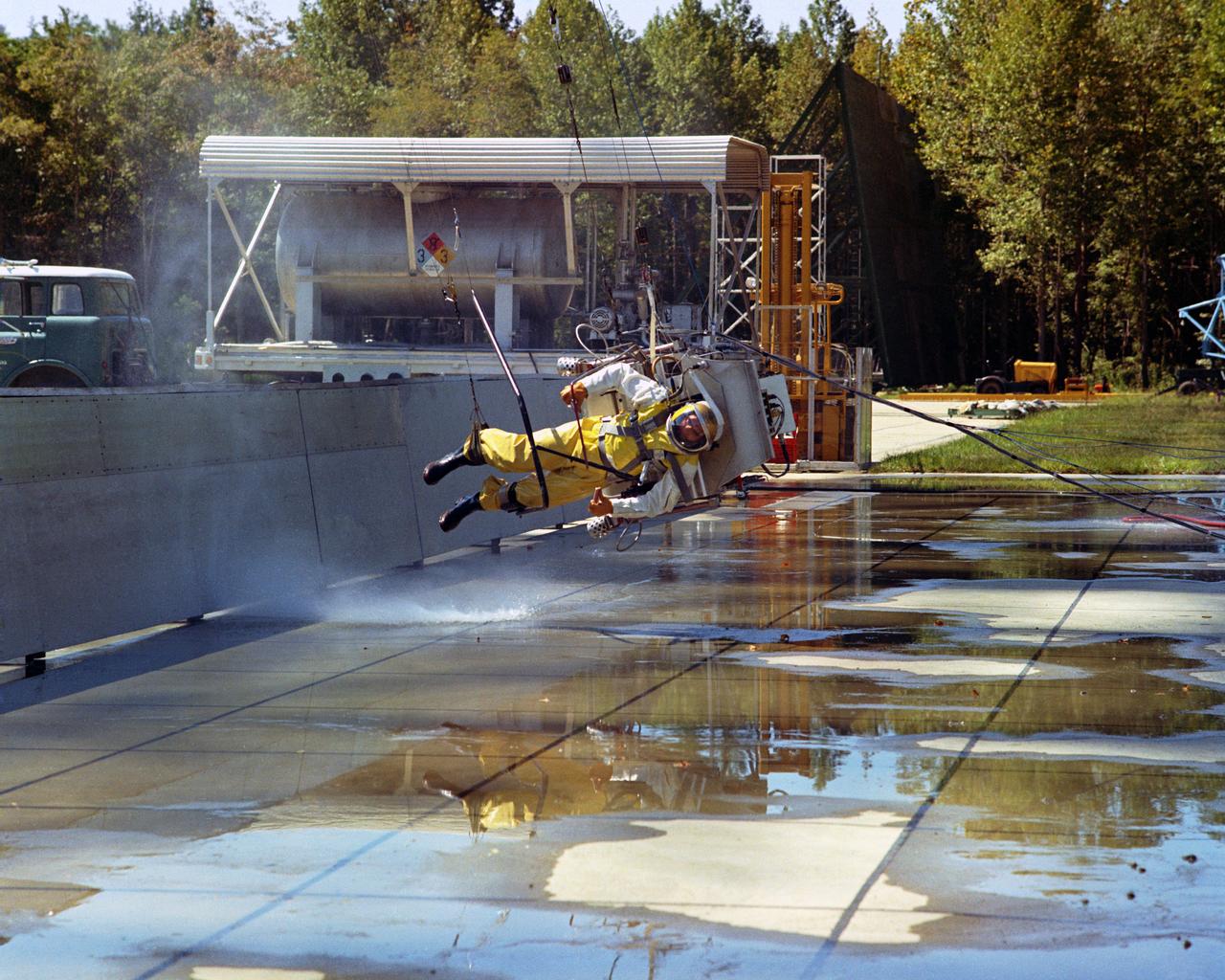
Icarus Lunar Walker,Lunar Landing Research Facility. Langley study of the backpack propulsion unit, by Bell Aerosystems. Icarus full scale test at Lunar Landing Research Facility - low gravity simulator. A NASA Langley researcher moon walks under the Lunar Landing Research Facility's gantry. More information on this can be read in the Document. "STUDIES OF PILOTING PROBLEMS OF ONE-MAN FLYING UNITS OPERATED IN SIMULATED LUNAR GRAVITY" BY Donald E. Hewes
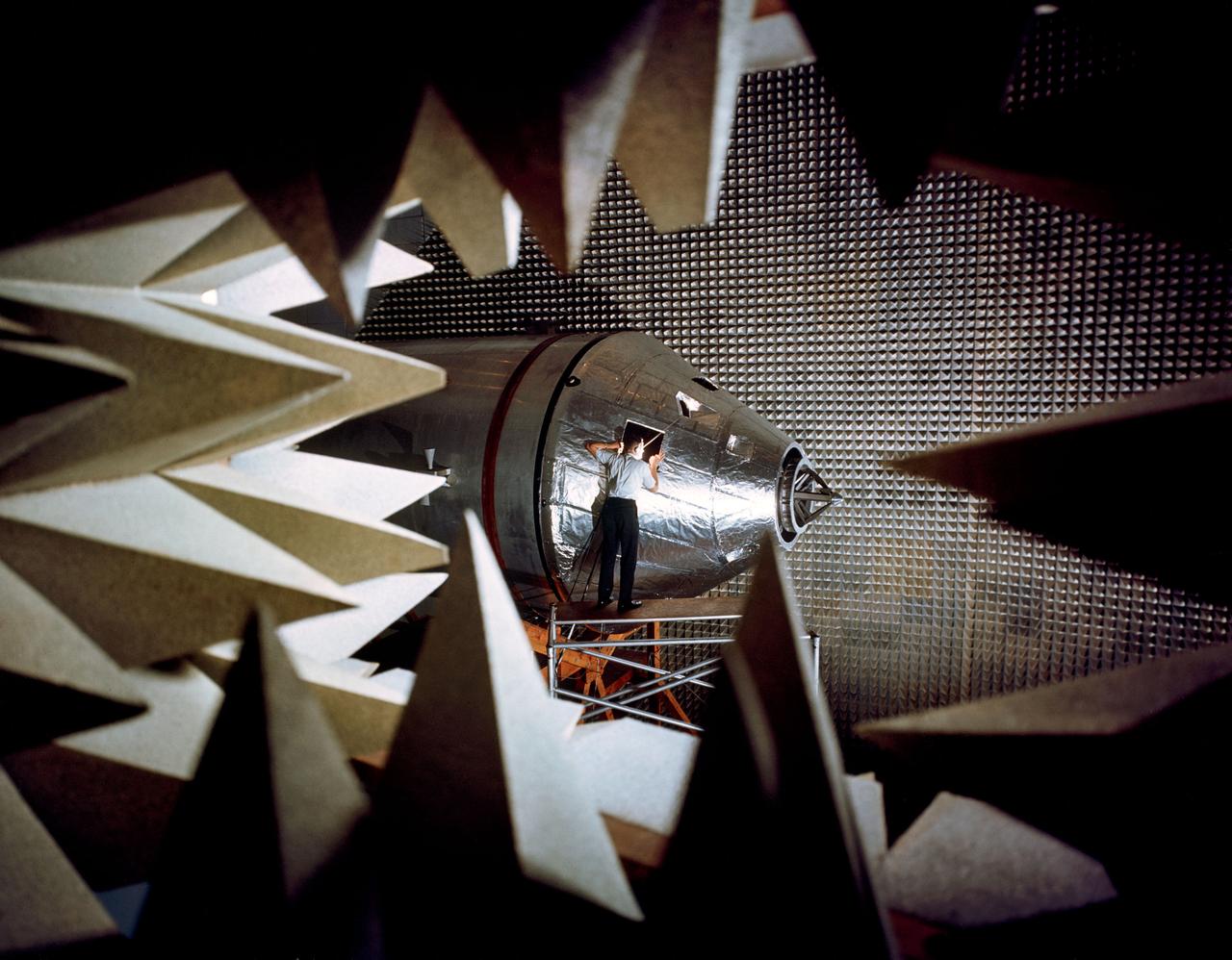
ASTRONAUT TRAINING APOLLO - LEM APOLLO MISSION SIMULATOR; NEUTRAL BOUYANCY FACILITY TANK; DYNAMIC CREW SIMULATOR; LUNAR MODULE SIMULATOR; CM PROCEDURES SIMULATOR; ANECHOIC CHAMBER;
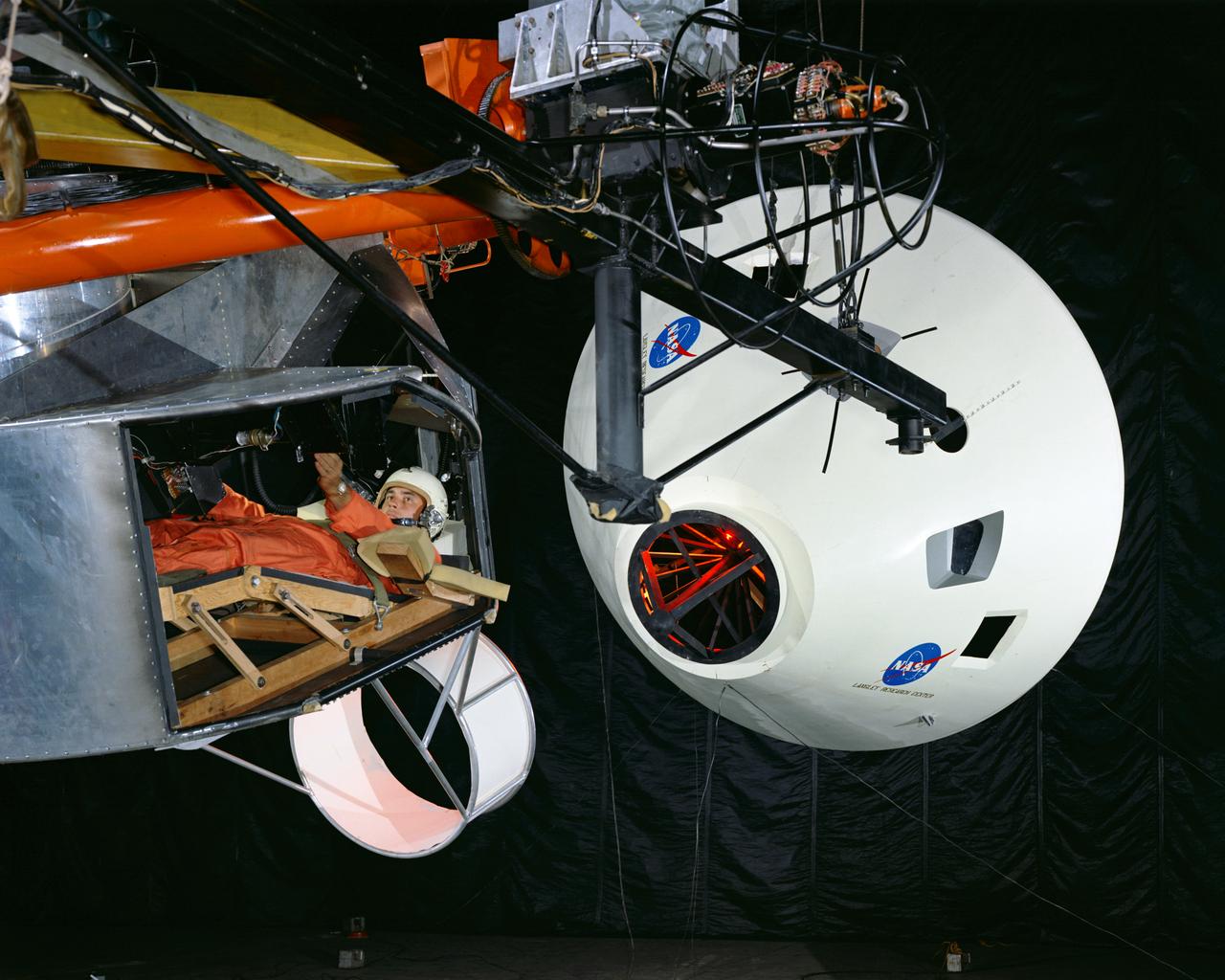
Simulator for Apollo Rendezvous Lunar Excursion Module (LEM)
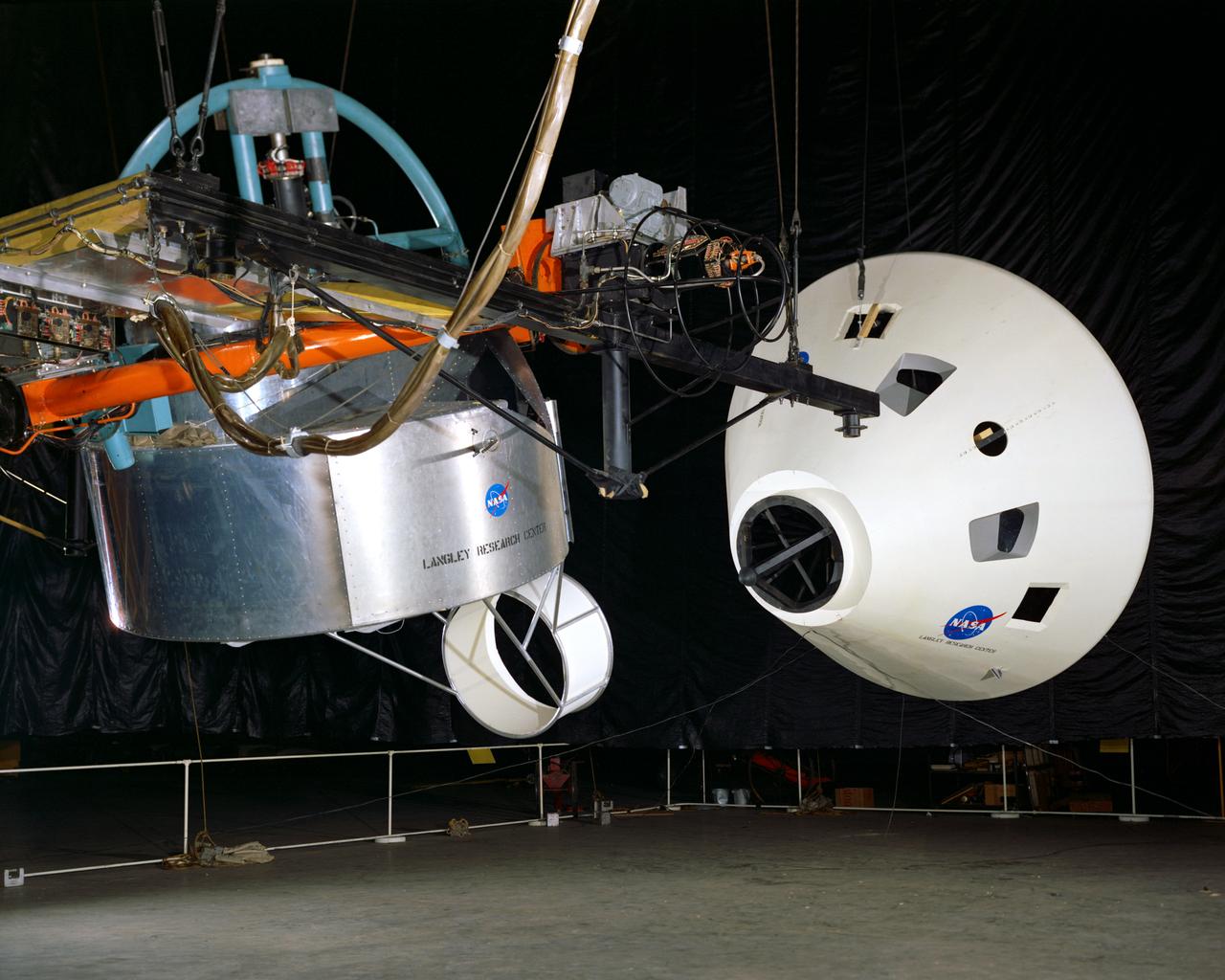
Simulator for Apollo Rendezvous Lunar Excursion Module (LEM)
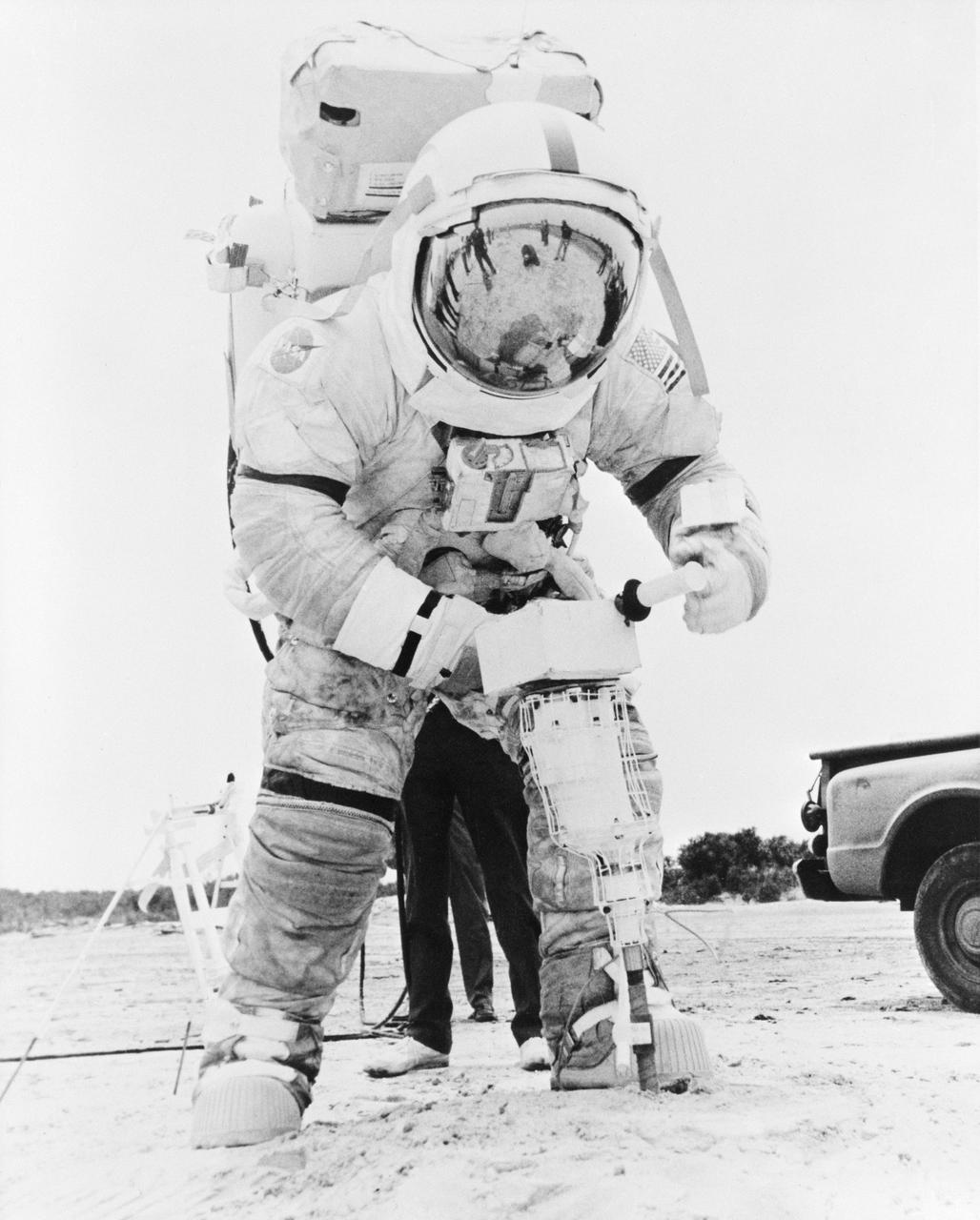
S72-44421 (June 1972) --- Astronaut Eugene A. Cernan, commander of the Apollo 17 lunar landing mission, practices with a lunar drill during lunar surface EVA simulations.
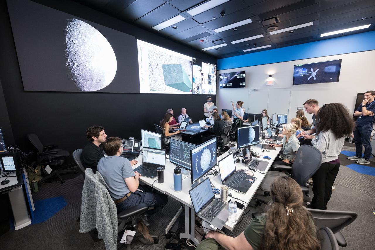
jsc2025e056603 --- The Artemis II Lunar Science Team runs a simulation of lunar observation operations in the new Science Evaluation Room (SER) that serves as a backroom to Mission Control.
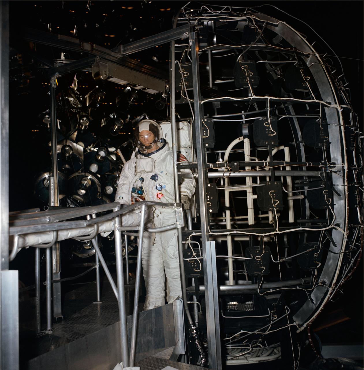
S68-55391 (11 Dec. 1968) --- Astronaut Russell L. Schweickart, lunar module pilot of the Apollo 9 (Spacecraft 104/Lunar Module 3/Saturn 504) space mission, is seen inside Chamber "A," Space Environment Simulation Laboratory, Building 32, participating in dry run activity in preparation for extravehicular activity which is scheduled in Chamber "A." The purpose of the scheduled training is to familiarize the crewmen with the operation of EVA equipment in a simulated space environment. In addition, metabolic and workload profiles will be simulated on each crewman. Astronauts Schweickart and Alan L. Bean, backup lunar module pilot, are scheduled to receive thermal-vacuum training simulating Earth-orbital EVA.
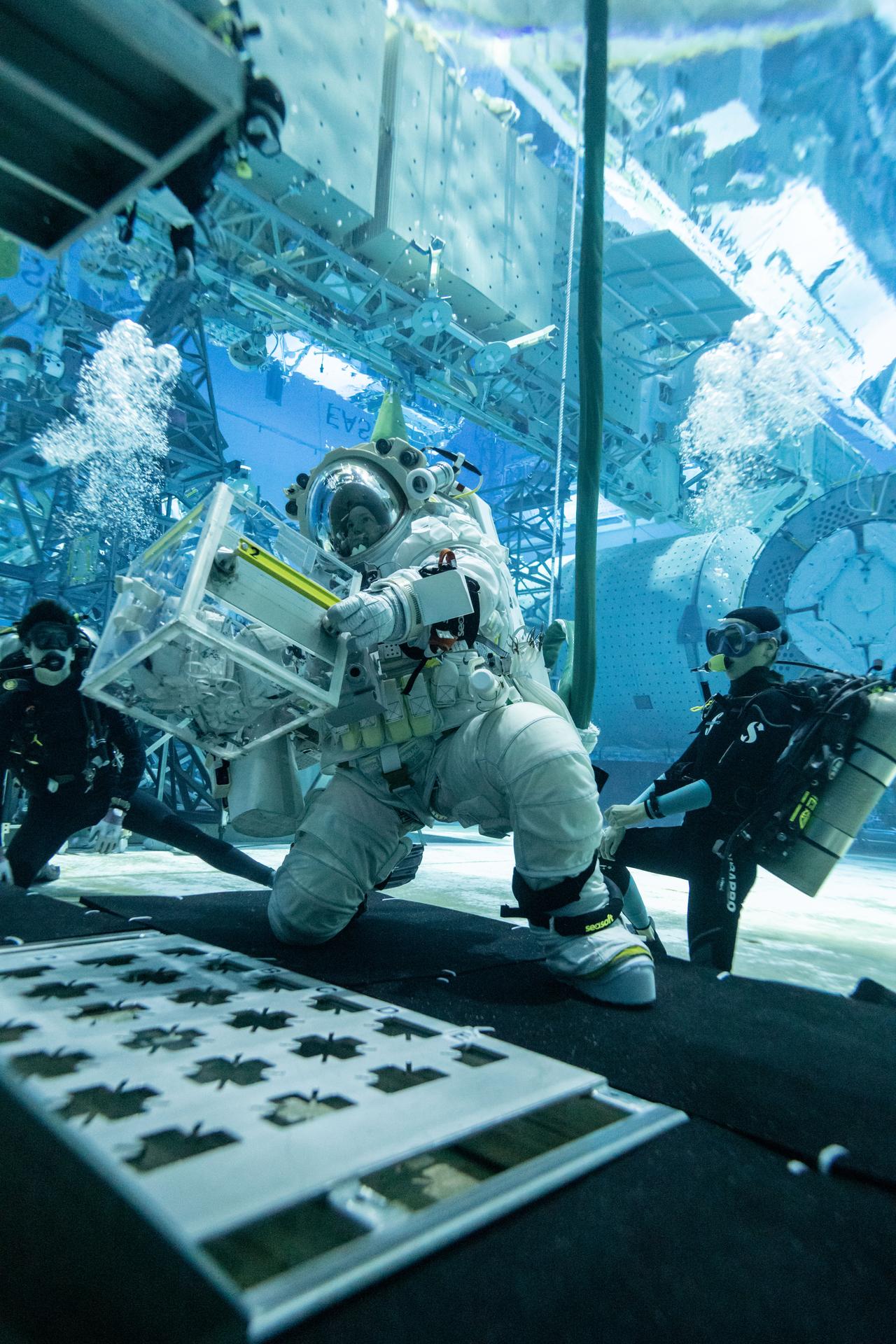
Canadian Space Agency astronaut Jenni Gibbons practices simulated lunar tasks under water while wearing Axiom Space’s lunar spacesuit at NASA’s Neutral Buoyancy Laboratory in Houston. During a recent test series, NASA engineers and crewmembers wore the lunar spacesuit under water and conducted numerous tasks during simulated lunar operations to test its mobility and functionality and ensure the spacesuit is prepped and ready for Artemis training.
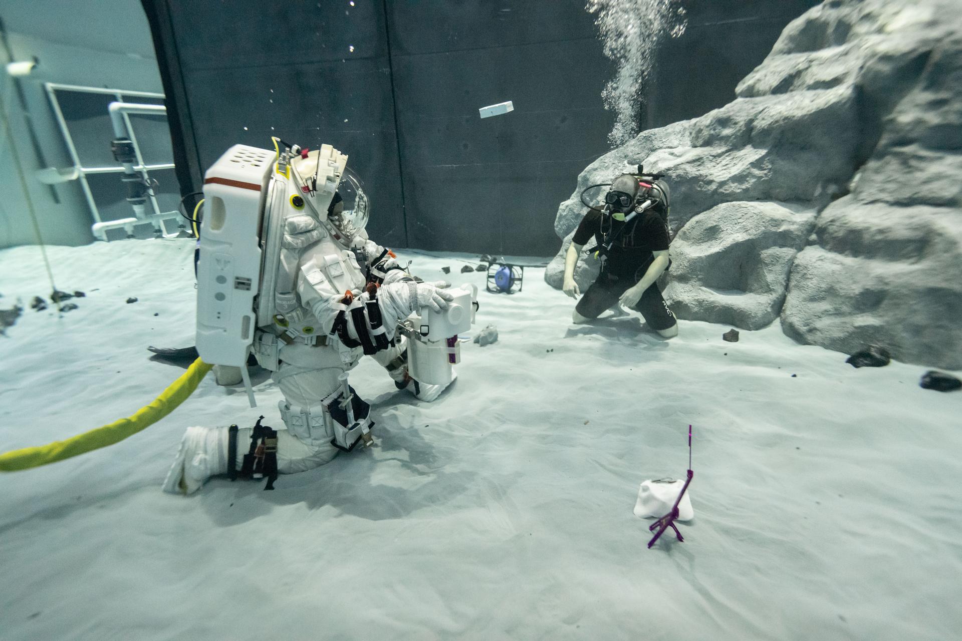
Canadian Space Agency astronaut Jenni Gibbons practices simulated lunar tasks under water while wearing Axiom Space’s lunar spacesuit at NASA’s Neutral Buoyancy Laboratory in Houston. During a recent test series, NASA engineers and crewmembers wore the lunar spacesuit under water and conducted numerous tasks during simulated lunar operations to test its mobility and functionality and ensure the spacesuit is prepped and ready for Artemis training.
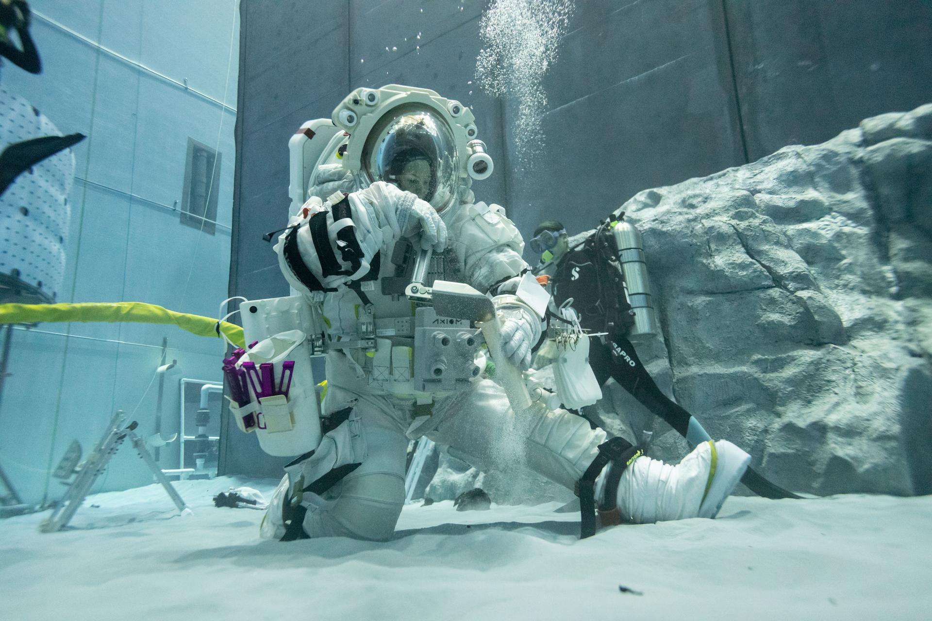
Canadian Space Agency astronaut Jenni Gibbons practices simulated lunar tasks under water while wearing Axiom Space’s lunar spacesuit at NASA’s Neutral Buoyancy Laboratory in Houston. During a recent test series, NASA engineers and crewmembers wore the lunar spacesuit under water and conducted numerous tasks during simulated lunar operations to test its mobility and functionality and ensure the spacesuit is prepped and ready for Artemis training.
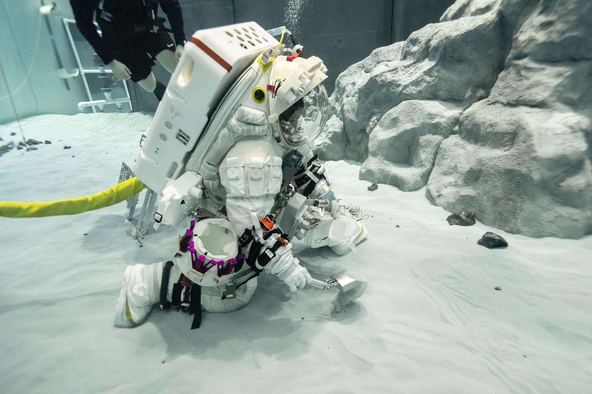
Canadian Space Agency astronaut Jenni Gibbons practices simulated lunar tasks under water while wearing Axiom Space’s lunar spacesuit at NASA’s Neutral Buoyancy Laboratory in Houston. During a recent test series, NASA engineers and crewmembers wore the lunar spacesuit under water and conducted numerous tasks during simulated lunar operations to test its mobility and functionality and ensure the spacesuit is prepped and ready for Artemis training.
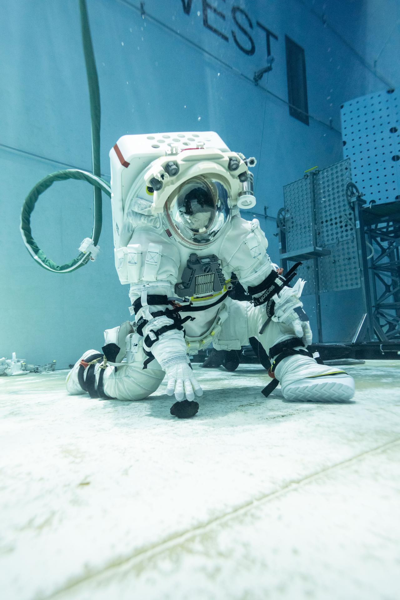
Canadian Space Agency astronaut Jenni Gibbons practices simulated lunar tasks under water while wearing Axiom Space’s lunar spacesuit at NASA’s Neutral Buoyancy Laboratory in Houston. During a recent test series, NASA engineers and crewmembers wore the lunar spacesuit under water and conducted numerous tasks during simulated lunar operations to test its mobility and functionality and ensure the spacesuit is prepped and ready for Artemis training.
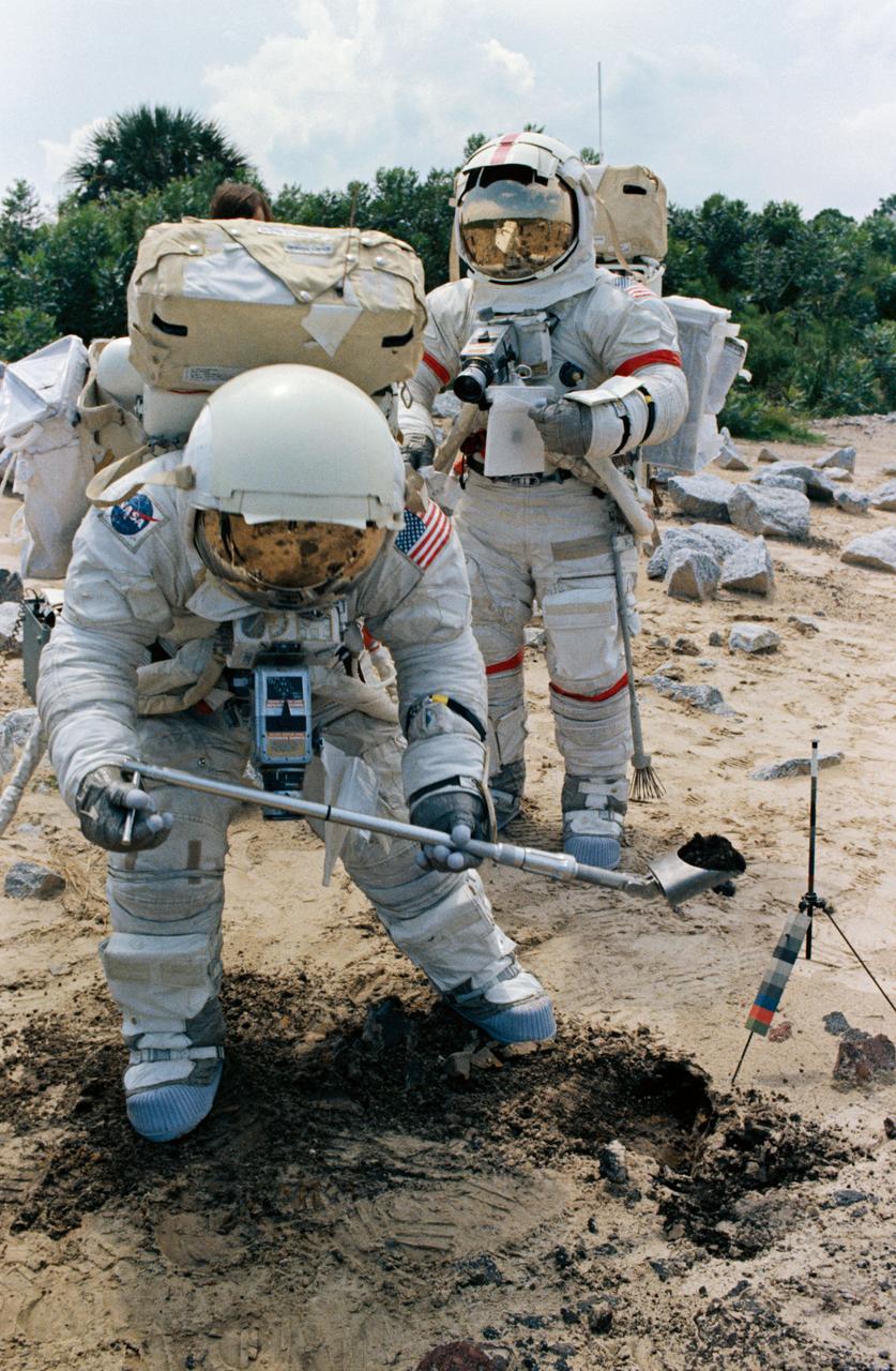
S72-48891 (September 1972) --- Two members of the prime crew of the Apollo 17 lunar landing mission participate in lunar surface extravehicular activity simulation training at the Kennedy Space Center, Florida. Scientist-astronaut Harrison H. Schmitt (foreground), lunar module pilot, simulates scooping up lunar sample material. Astronaut Eugene A. Cernan (background), commander, holds a sample bag.
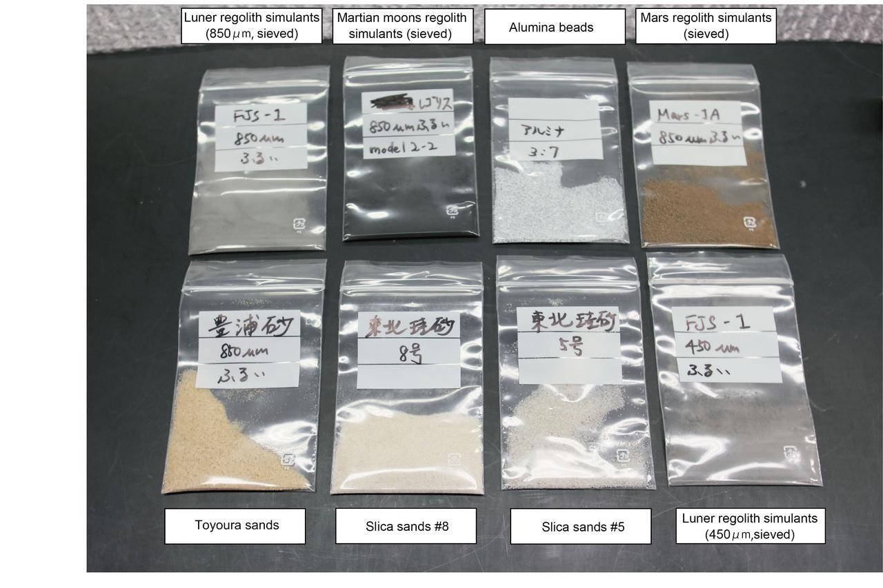
View of Hourglass samples including Lunar regolith simulants, Martian moons regolith simulants, Alumina beads, Mars regolith simulants, Toyoura sands and Slica sands. (Image courtesy of: JAXA)
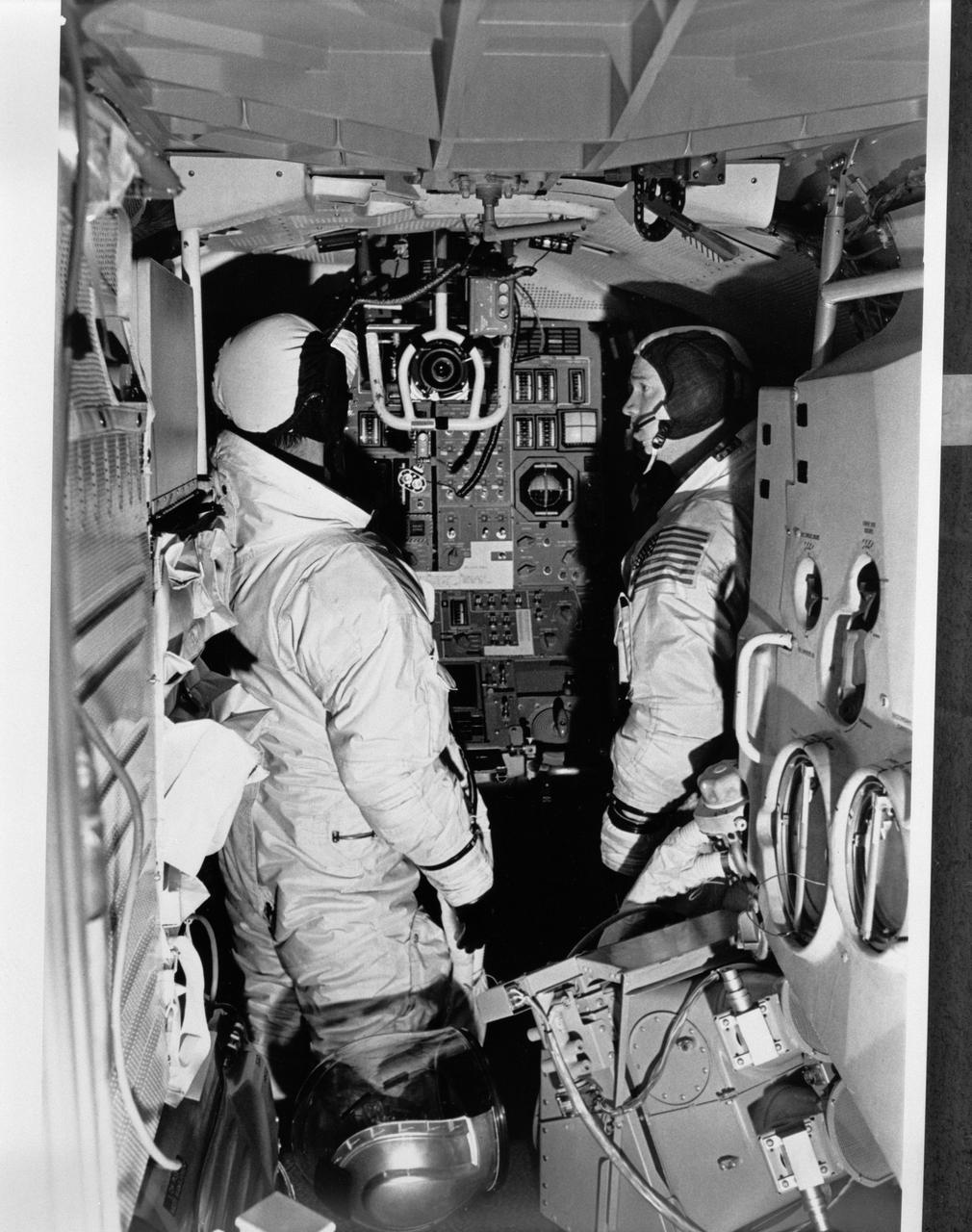
S69-19858 (December 1968) --- Two members of the Apollo 9 prime crew participate in simulation training in the Apollo Lunar Module Mission Simulator (LMMS) at the Kennedy Space Center (KSC). On the left is astronaut James A. McDivitt, commander; and on the right is astronaut Russell L. Schweickart, lunar module pilot.
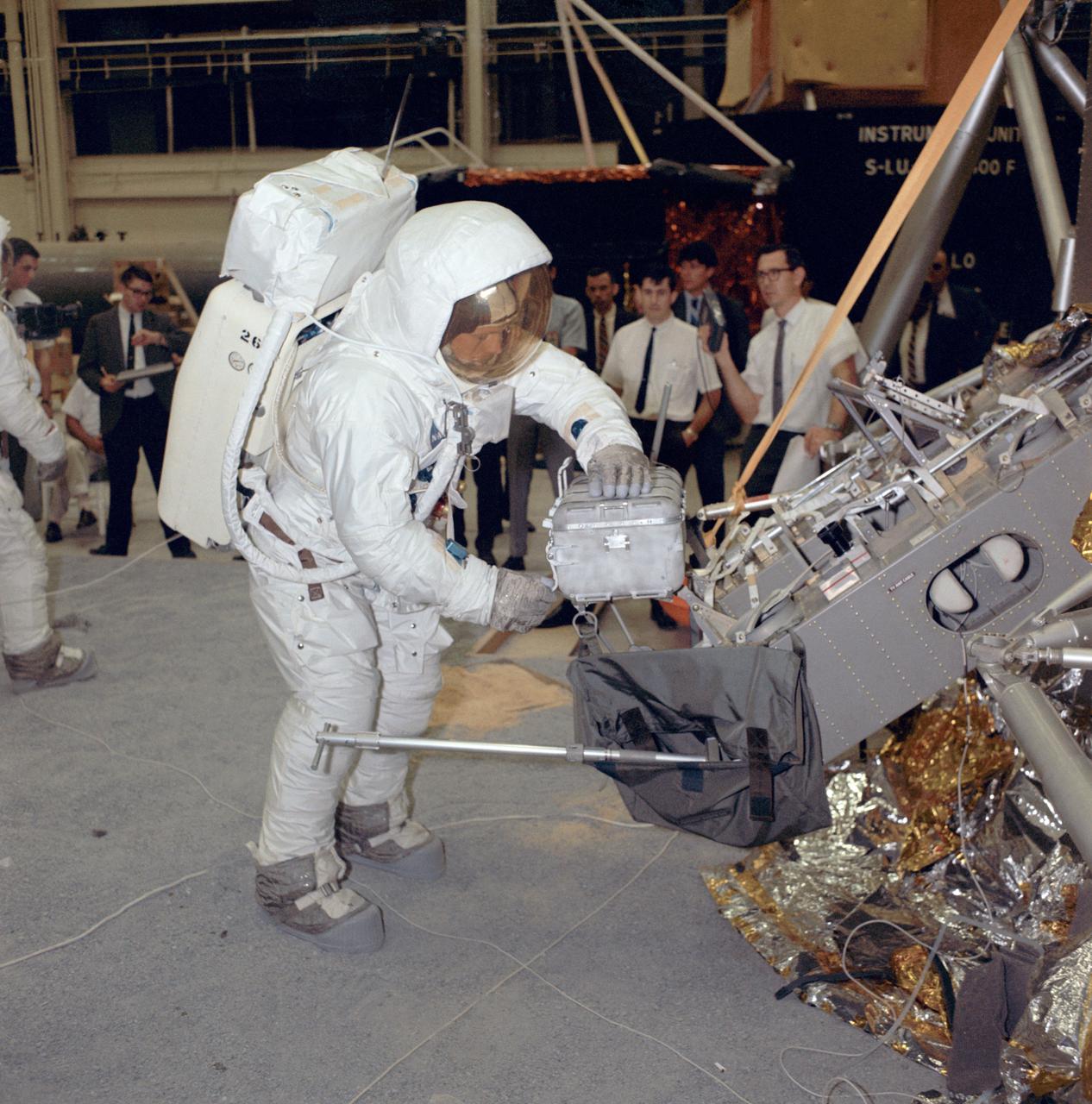
Apollo 11 commander Neil Armstrong works with an Apollo Lunar Sample Return Container during a two-and-a-half-hour lunar surface simulation training exercise. The image was taken on Apr. 18, 1969, in Building 9 at the Manned Spacecraft Center in Houston, Texas. The sample tubes carried by NASA's Mars 2020 Perseverance rover are destined to carry the first samples in history from another planet back to Earth. Future scientists will use these carefully selected representatives of Martian rock and regolith (broken rock and dust), to look for evidence of potential microbial life present in Mars' ancient past and to answer other key questions about Mars and its history. Perseverance will land at Mars' Jezero Crater on Feb. 18, 2021. https://photojournal.jpl.nasa.gov/catalog/PIA24297
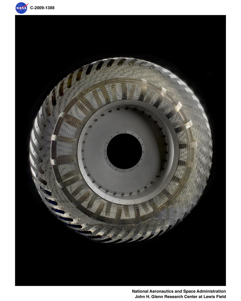
Wire Mesh Tire from the Simulated Lunar Operations Laboratory (SLOPE Lab)
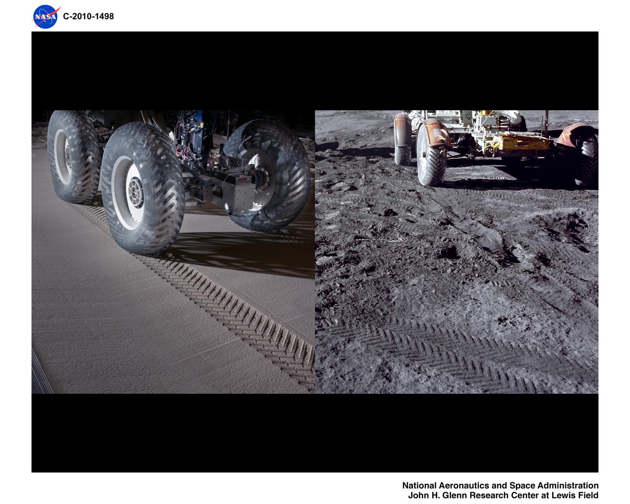
Simulated Lunar Operations Laboratory (SLOPE), Surface Mobility Research
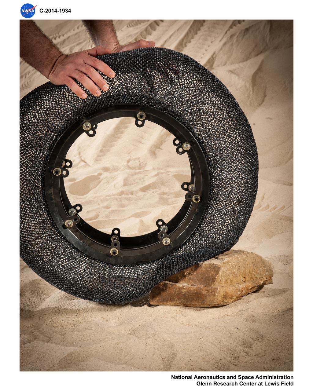
Airless Spring Wheel Prototype in the Simulated Lunar Operations Laboratory, SLOPE Lab
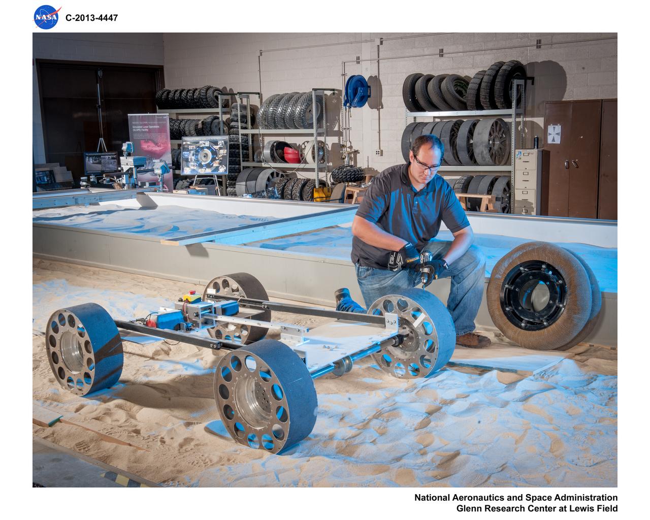
Fabrication of rover spring tires in the Simulated Lunar Operations, SLOPe Lab, Laboratory