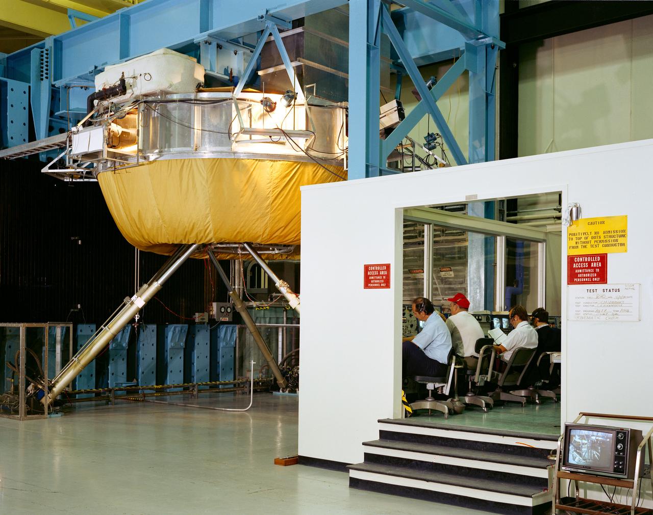
S74-27049 (4 Aug. 1974) --- Overall view of test set-up in Building 23 at the Johnson Space Center during testing of the docking mechanisms for the joint U.S.-USSR Apollo-Soyuz Test Project. The cinematic check was being made when this picture was taken. The test control room is on the right. The Soviet-developed docking system is atop the USA-NASA developed docking system. Both American and Soviet engineers can be seen taking part in the docking testing. The ASTP docking mission in Earth orbit is scheduled for July 1975.
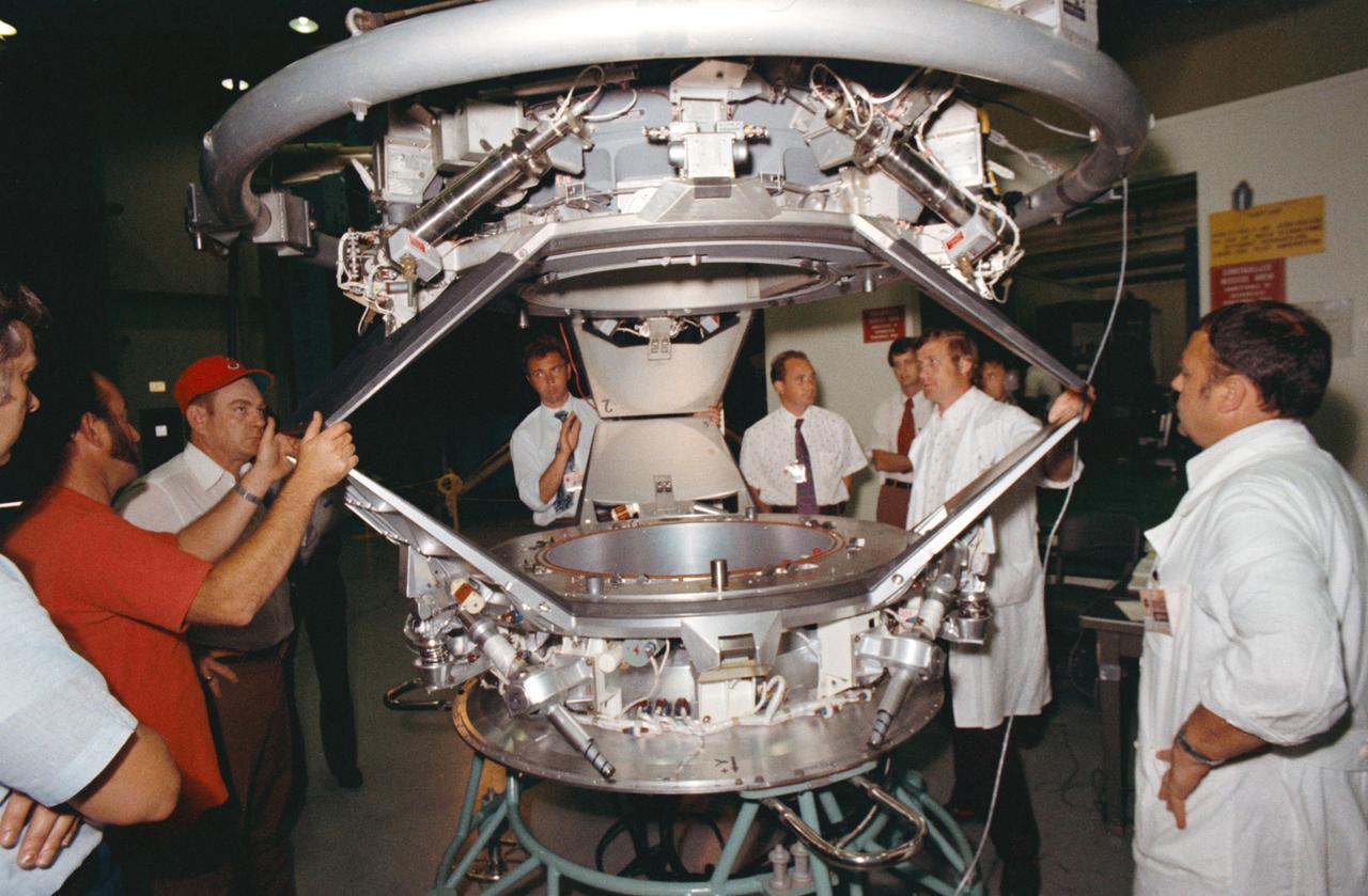
S74-25394 (10 July 1974) --- A group of American and Soviet engineers of the Apollo-Soyuz Test Project working group three examines an ASTP docking set-up following a docking mechanism fitness test conducted in Building 13 at the Johnson Space Center. Working Group No. 3 is concerned with ASTP docking problems and techniques. The joint U.S.-USSR ASTP docking mission in Earth orbit is scheduled for the summer of 1975. The Apollo docking mechanism is atop the Soyuz docking mechanism.
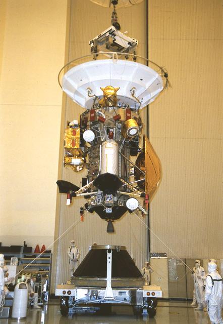
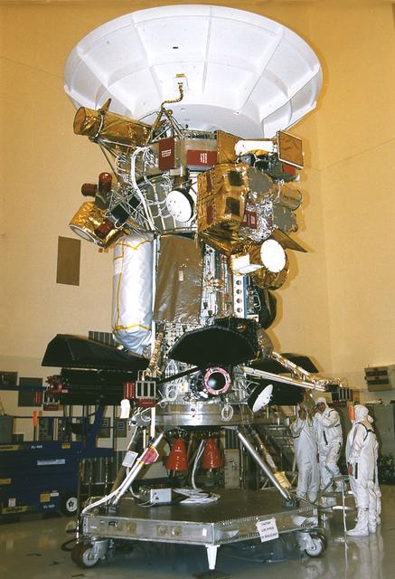
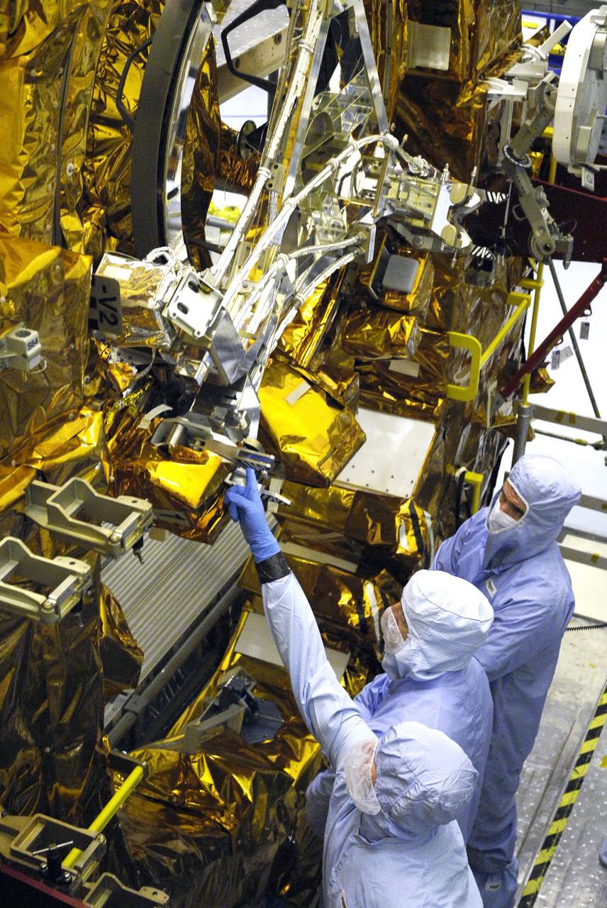
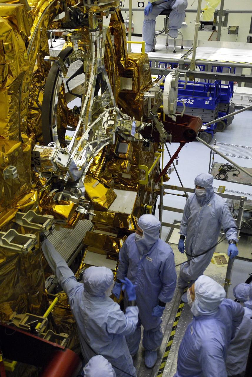
Jet Propulsion Research Lab (JPL) workers use a borescope to verify the pressure relief device bellow's integrity on a radioisotope thermoelectric generator (RTG) that has been installed on the Cassini spacecraft in the Payload Hazardous Servicing Facility. The activity is part of the mechanical and electrical verification testing of RTGs during prelaunch processing. RTGs use heat from the natural decay of plutonium to generate electrical power. The three RTGs on Cassini will enable the spacecraft to operate far from the Sun where solar power systems are not feasible. They will provide electrical power to Cassini on it seven year trip to the Saturnian system and during its four year mission at Saturn.
Jet Propulsion Research Lab (JPL) workers use a borescope to verify the pressure relief device bellow's integrity on a radioisotope thermoelectric generator (RTG) that has been installed on the Cassini spacecraft in the Payload Hazardous Servicing Facility. The activity is part of the mechanical and electrical verification testing of RTGs during prelaunch processing. RTGs use heat from the natural decay of plutonium to generate electrical power. The three RTGs on Cassini will enable the spacecraft to operate far from the Sun where solar power systems are not feasible. They will provide electrical power to Cassini on it seven year trip to the Saturnian system and during its four year mission at Saturn.
CAPE CANAVERAL, Fla. – In the Payload Hazardous Servicing Facility at NASA’s Kennedy Space Center, crew members with the STS-125 mission get a close look at some of the equipment associated with their mission to service NASA’s Hubble Space Telescope. Looking at the Soft Capture Mechanism on the Flight Support Structure are a technician (pointing) and Mission Specialists Mike Massimino and Michael Good. The mechanism will enable the future rendezvous, capture and safe disposal of NASA's Hubble Space Telescope by either a crewed or robotic mission. The ring-like device attaches to Hubble’s aft bulkhead. The STS-125 crew is taking part in a crew equipment interface test, which provides experience handling tools, equipment and hardware they will use on their mission. Space shuttle Atlantis is targeted to launch on the STS-125 mission Oct. 10. Photo credit: NASA/Kim Shiflett
CAPE CANAVERAL, Fla. – In the Payload Hazardous Servicing Facility at NASA’s Kennedy Space Center, crew members with the STS-125 mission get a close look at some of the equipment associated with their mission to service NASA’s Hubble Space Telescope. A technician, at left, provides information about the Soft Capture Mechanism on the Flight Support Structure to Mission Specialists Michael Good, Andrew Feustel and Mike Massimino. The mechanism will enable the future rendezvous, capture and safe disposal of NASA's Hubble Space Telescope by either a crewed or robotic mission. The ring-like device attaches to Hubble’s aft bulkhead. The STS-125 crew is taking part in a crew equipment interface test, which provides experience handling tools, equipment and hardware they will use on their mission. Space shuttle Atlantis is targeted to launch on the STS-125 mission Oct. 10. Photo credit: NASA/Kim Shiflett

CAPE CANAVERAL, Fla. – In the Payload Hazardous Servicing Facility at NASA’s Kennedy Space Center, crew members with the STS-125 mission get a close look at some of the equipment associated with their mission to service NASA’s Hubble Space Telescope. Mission Specialist Michael Good points out part of the Flight Support Structure to Mission Specialist Andrew Feustel, right. The Soft Capture Mechanism is above him. The mechanism will enable the future rendezvous, capture and safe disposal of NASA's Hubble Space Telescope by either a crewed or robotic mission. The ring-like device attaches to Hubble’s aft bulkhead. The STS-125 crew is taking part in a crew equipment interface test, which provides experience handling tools, equipment and hardware they will use on their mission. Space shuttle Atlantis is targeted to launch on the STS-125 mission Oct. 10. Photo credit: NASA/Kim Shiflett
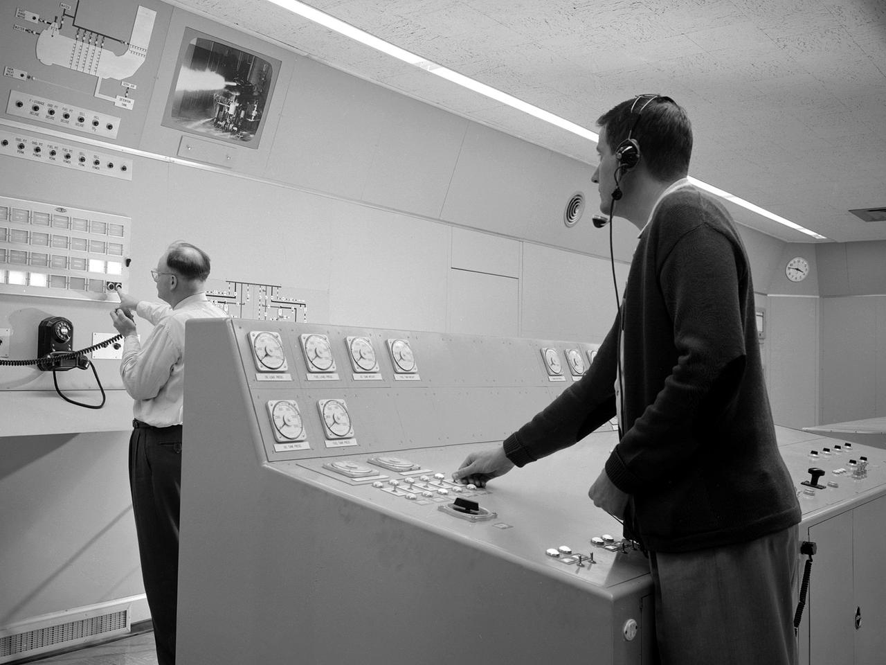
Test engineers monitor an engine firing from the control room of the Rocket Engine Test Facility at the National Advisory Committee for Aeronautics (NACA) Lewis Flight Propulsion Laboratory. The Rocket Engine Test Facility, built in the early 1950s, had a rocket stand designed to evaluate high-energy propellants and rocket engine designs. The facility was used to study numerous different types of rocket engines including the Pratt and Whitney RL-10 engine for the Centaur rocket and Rocketdyne’s F-1 and J-2 engines for the Saturn rockets. The Rocket Engine Test Facility was built in a ravine at the far end of the laboratory because of its use of the dangerous propellants such as liquid hydrogen and liquid fluorine. The control room was located in a building 1,600 feet north of the test stand to protect the engineers running the tests. The main control and instrument consoles were centrally located in the control room and surrounded by boards controlling and monitoring the major valves, pumps, motors, and actuators. A camera system at the test stand allowed the operators to view the tests, but the researchers were reliant on data recording equipment, sensors, and other devices to provide test data. The facility’s control room was upgraded several times over the years. Programmable logic controllers replaced the electro-mechanical control devices. The new controllers were programed to operate the valves and actuators controlling the fuel, oxidant, and ignition sequence according to a predetermined time schedule.
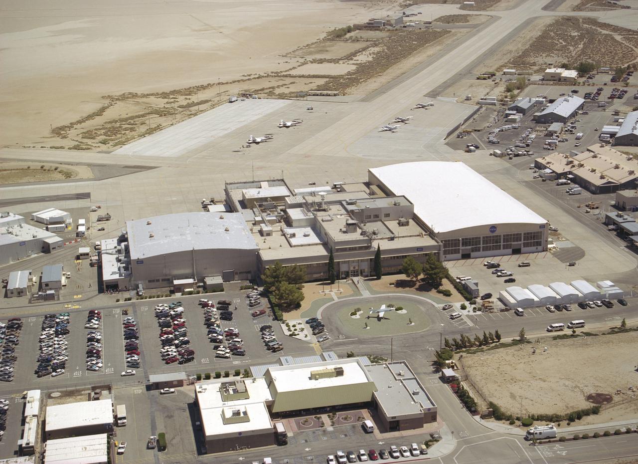
Since the 1940s the Dryden Flight Research Center, Edwards, California, has developed a unique and highly specialized capability for conducting flight research programs. The organization, made up of pilots, scientists, engineers, technicians, and mechanics, has been and will continue to be leaders in the field of advanced aeronautics. Located on the northwest "shore" of Rogers Dry Lake, the complex was built around the original administrative-hangar building constructed in 1954. Since then many additional support and operational facilities have been built including a number of unique test facilities such as the Thermalstructures Research Facility, Flow Visualization Facility, and the Integrated Test Facility. One of the most prominent structures is the space shuttle program's Mate-Demate Device and hangar in Area A to the north of the main complex. On the lakebed surface is a Compass Rose that gives pilots an instant compass heading. The Dryden complex originated at Edwards Air Force Base in support of the X-1 supersonic flight program. As other high-speed aircraft entered research programs, the facility became permanent and grew from a staff of five engineers in 1947 to a population in 2006 of nearly 1100 full-time government and contractor employees.
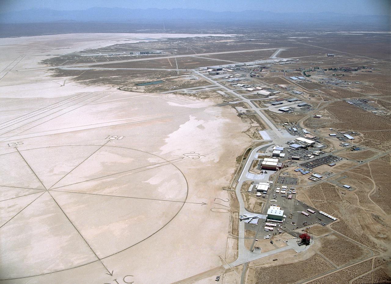
Since the 1940s the Dryden Flight Research Center, Edwards, California, has developed a unique and highly specialized capability for conducting flight research programs. The organization, made up of pilots, scientists, engineers, technicians, and mechanics, has been and will continue to be leaders in the field of advanced aeronautics. Located on the northwest "shore" of Rogers Dry Lake, the complex was built around the original administrative-hangar building constructed in 1954. Since then many additional support and operational facilities have been built including a number of unique test facilities such as the Thermalstructures Research Facility, Flow Visualization Facility, and the Integrated Test Facility. One of the most prominent structures is the space shuttle program's Mate-Demate Device and hangar in Area A to the north of the main complex. On the lakebed surface is a Compass Rose that gives pilots an instant compass heading. The Dryden complex originated at Edwards Air Force Base in support of the X-1 supersonic flight program. As other high-speed aircraft entered research programs, the facility became permanent and grew from a staff of five engineers in 1947 to a population in 2006 of nearly 1100 full-time government and contractor employees.
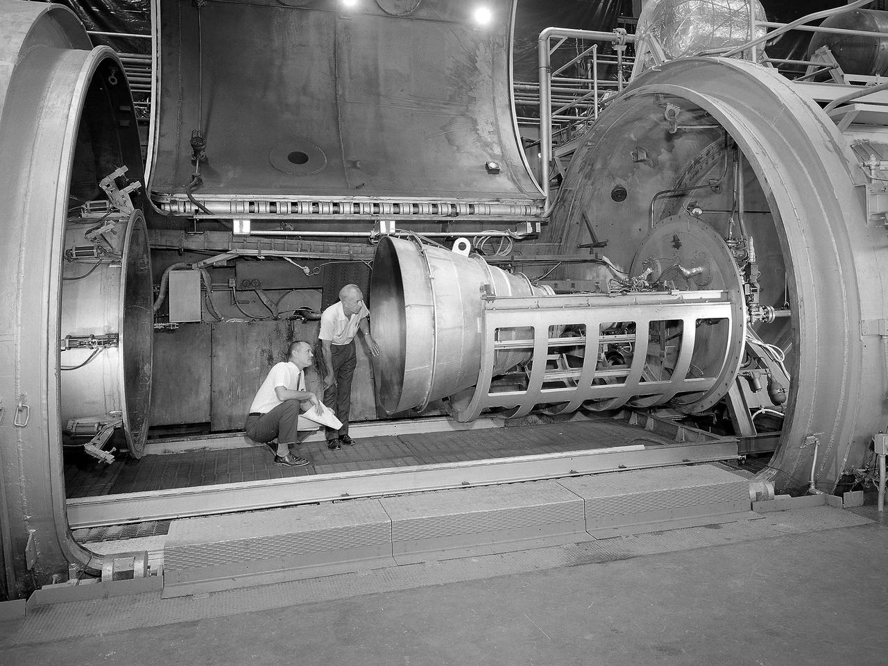
Bill Harrison and Bud Meilander check the setup of an Apollo Contour rocket nozzle in the Propulsion Systems Laboratory at the National Aeronautics and Space Administration (NASA) Lewis Research Center. The Propulsion Systems Laboratory contained two 14-foot diameter test chambers that could simulate conditions found at very high altitudes. The facility was used in the 1960s to study complex rocket engines such as the Pratt and Whitney RL-10 and rocket components such as the Apollo Contour nozzle, seen here. Meilander oversaw the facility’s mechanics and the installation of test articles into the chambers. Harrison was head of the Supersonic Tunnels Branch in the Test Installations Division. Researchers sought to determine the impulse value of the storable propellant mix, classify and improve the internal engine performance, and compare the results with analytical tools. A special setup was installed in the chamber that included a device to measure the thrust load and a calibration stand. Both cylindrical and conical combustion chambers were examined with the conical large area ratio nozzles. In addition, two contour nozzles were tested, one based on the Apollo Service Propulsion System and the other on the Air Force’s Titan transtage engine. Three types of injectors were investigated, including a Lewis-designed model that produced 98-percent efficiency. It was determined that combustion instability did not affect the nozzle performance. Although much valuable information was obtained during the tests, attempts to improve the engine performance were not successful.
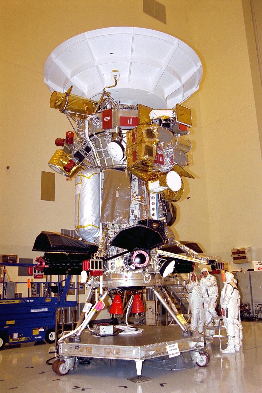
Jet Propulsion Laboratory (JPL) workers use a borescope to verify pressure relief device bellows integrity on a radioisotope thermoelectric generator (RTG) which has been installed on the Cassini spacecraft in the Payload Hazardous Servicing Facility. The activity is part of the mechanical and electrical verification testing of RTGs during prelaunch processing. RTGs use heat from the natural decay of plutonium to generate electric power. The three RTGs on Cassini will enable the spacecraft to operate far from the Sun where solar power systems are not feasible. They will provide electrical power to Cassini on its 6.7-year trip to the Saturnian system and during its four-year mission at Saturn. The Cassini mission is scheduled for an Oct. 6 launch aboard a Titan IVB/Centaur expendable launch vehicle. Cassini is built and managed for NASA by JPL

An inlet duct lowered into the 20-foot diameter test section of the Altitude Wind Tunnel at the National Advisory Committee for Aeronautics (NACA) Lewis Flight Propulsion Laboratory. Engines and hardware were prepared in the facility’s shop area. The test articles were lifted by a two-rail Shaw box crane through the high-bay and the second-story test chamber before being lowered into the test section. Technicians then spent days or weeks hooking up the supply lines and data recording telemetry. The engines were mounted on wingspans that stretched across the test section. The wingtips attached to the balance frame’s trunnions, which could adjust the angle of attack. The balance frame included six devices that recorded data and controlled the engine. The measurements were visible in banks of manometer boards next to the control room. Photographs recorded the pressure levels in the manometer tubes, and the computing staff manually converted the data into useful measurements. A mechanical pulley system was used to raise and lower the tunnel’s large clamshell lid into place. The lid was sealed into place using hand-turned locks accessible from the viewing platform. The lid had viewing windows above and below the test article, which permitted the filming and visual inspection of the tests.
![Test subject wearing jet-shoe apparatus and resting in sling support. The cables are not attached. From A.W. Vogeley, "Piloted Space-Flight Simulation at Langley Research Center," Paper presented at the American Society of Mechanical Engineers, 1966 Winter Meeting, New York, NY, November 27 - December 1, 1966. "As mentioned previously, Langley is conducting in-house and contract studies of extra-vehicular activities wherein zero gravity is simulated by the water-immersion technique. ... Water immersion is a very useful technique where motions are slow. When more rapid motion is required, as in studying one-man propulsion systems, other approaches are required. For these studies Langley has been using the RDS [Rendezvous Docking Simulator] in a manner similar to the LLRF [Lunar Landing Research Facility] technique. The test subjects are suspended in a sling support from a single RDS cable. As they translate about, the RDS tracks them, keeping the cable vertical. The test subjects operate in an effectively zero g environment in the horizontal plane. Tracking was originally done visually using closed-circuit TV, but recently a fast-response servo system using cable angle sensors has provided better operation. Some results of tests where subjects moved about merely by jumping and also where propulsion in the form of simple "jet-shoes" was provided are given in reference 20. Both methods, within limits, appear feasible. Full six-degree-of-freedom equipment for studies of more sophisticated one-man propulsion systems is now being procured. Called OMPRA (One-Man Propulsion Research Apparatus), the device will provide a gimbal system for rotational freedom, a quick response vertical servo for this translational freedom that is not now feasible with the RDS, and a versatile maneuvering unit."](https://images-assets.nasa.gov/image/LRC-1967-B701_P-01373/LRC-1967-B701_P-01373~medium.jpg)
Test subject wearing jet-shoe apparatus and resting in sling support. The cables are not attached. From A.W. Vogeley, "Piloted Space-Flight Simulation at Langley Research Center," Paper presented at the American Society of Mechanical Engineers, 1966 Winter Meeting, New York, NY, November 27 - December 1, 1966. "As mentioned previously, Langley is conducting in-house and contract studies of extra-vehicular activities wherein zero gravity is simulated by the water-immersion technique. ... Water immersion is a very useful technique where motions are slow. When more rapid motion is required, as in studying one-man propulsion systems, other approaches are required. For these studies Langley has been using the RDS [Rendezvous Docking Simulator] in a manner similar to the LLRF [Lunar Landing Research Facility] technique. The test subjects are suspended in a sling support from a single RDS cable. As they translate about, the RDS tracks them, keeping the cable vertical. The test subjects operate in an effectively zero g environment in the horizontal plane. Tracking was originally done visually using closed-circuit TV, but recently a fast-response servo system using cable angle sensors has provided better operation. Some results of tests where subjects moved about merely by jumping and also where propulsion in the form of simple "jet-shoes" was provided are given in reference 20. Both methods, within limits, appear feasible. Full six-degree-of-freedom equipment for studies of more sophisticated one-man propulsion systems is now being procured. Called OMPRA (One-Man Propulsion Research Apparatus), the device will provide a gimbal system for rotational freedom, a quick response vertical servo for this translational freedom that is not now feasible with the RDS, and a versatile maneuvering unit."