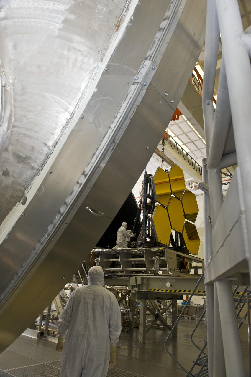
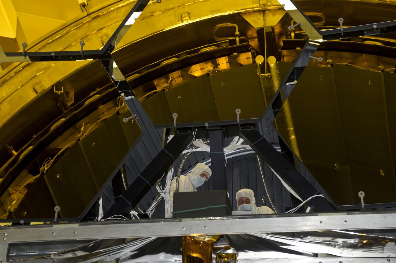
MARSHALL TEST ENGINEER HARLAN HAIGHT HELPS PULL JWST MIRROR ARRAY FROM CRYOGENICS CHAMBER.
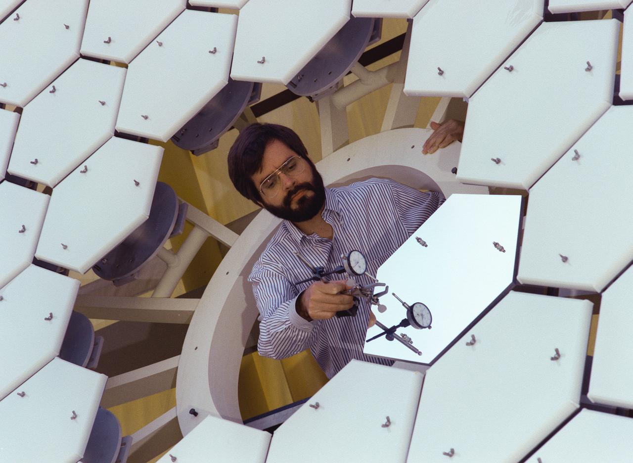
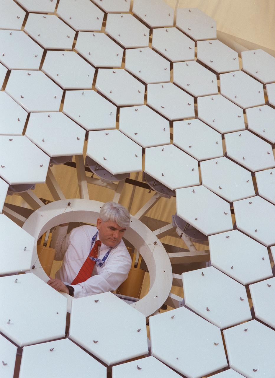
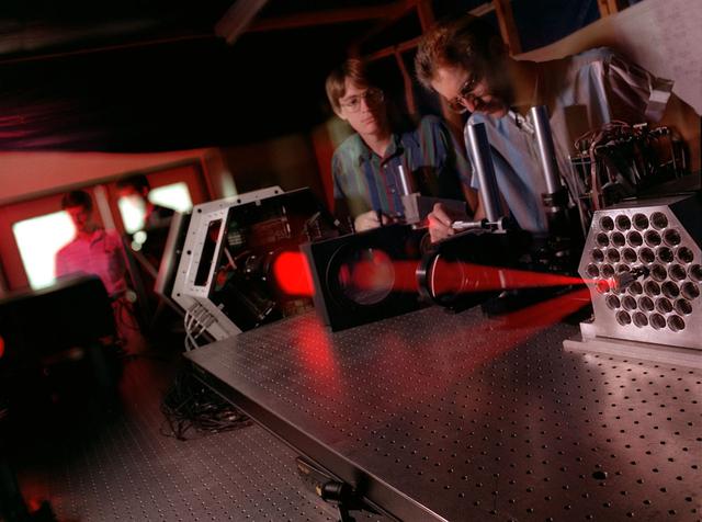
NASA's Space Optics Manufacturing Technology Center has been working to expand our view of the universe via sophisticated new telescopes. The Optics Center's goal is to develop low-cost, advanced space optics technologies for the NASA program in the 21st century, including the long-term goal of imaging Earth-like planets in distant solar systems. A segmented array of mirrors was designed by the Space Optics Manufacturing Technology Center for the solar concentrator test stand at the Marshall Space Flight Center (MSFC) for powering solar thermal propulsion engines. Each hexagon mirror has a spherical surface to approximate a parabolic concentrator when combined into the entire 18-foot diameter array. The aluminum mirrors were polished with a diamond turning machine that creates a glass-like reflective finish on metal. The precision fabrication machinery at the Space Optics Manufacturing Technology Center at MSFC can polish specialized optical elements to a world class quality of smoothness. This image shows optics physicist, Vince Huegele, examining one of the 144-segment hexagonal mirrors of the 18-foot diameter array at the MSFC solar concentrator test stand.
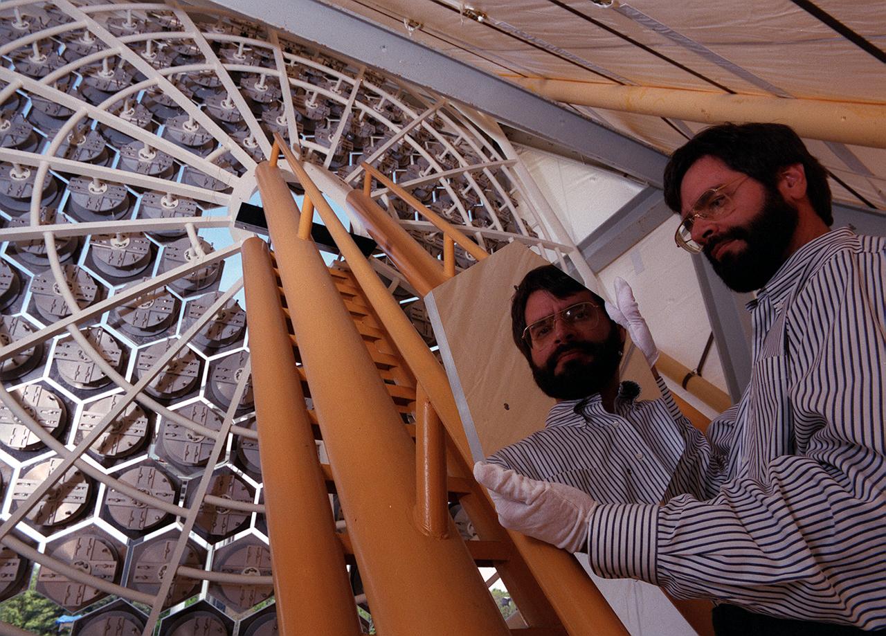
NASA's Space Optics Manufacturing Technology Center has been working to expand our view of the universe via sophisticated new telescopes. The Optics Center's goal is to develop low-cost, advanced space optics technologies for the NASA program in the 21st century, including the long-term goal of imaging Earth-like planets in distant solar systems. A segmented array of mirrors was designed by the Space Optics Manufacturing Technology Center for solar the concentrator test stand at the Marshall Space Flight Center (MSFC) for powering solar thermal propulsion engines. Each hexagon mirror has a spherical surface to approximate a parabolic concentrator when combined into the entire 18-foot diameter array. The aluminum mirrors were polished with a diamond turning machine, that creates a glass-like reflective finish on metal. The precision fabrication machinery at the Space Optics Manufacturing Technology Center at MSFC can polish specialized optical elements to a world class quality of smoothness. This image shows optics physicist, Vince Huegele, examining one of the 144-segment hexagonal mirrors of the 18-foot diameter array at the MSFC solar concentrator test stand.
NASA Nuclear Spectroscopic Telescope Array, or NuSTAR, has a complex set of mirrors, or optics, that will help it see high-energy X-ray light in greater detail than ever before.
A team of engineers at Marshall Space Flight Center (MSFC) has designed, fabricated, and tested the first solar thermal engine, a non-chemical rocket that produces lower thrust but has better thrust efficiency than the chemical combustion engines. This segmented array of mirrors is the solar concentrator test stand at MSFC for firing the thermal propulsion engines. The 144 mirrors are combined to form an 18-foot diameter array concentrator. The mirror segments are aluminum hexagons that have the reflective surface cut into it by a diamond turning machine, which is developed by MSFC Space Optics Manufacturing Technology Center.
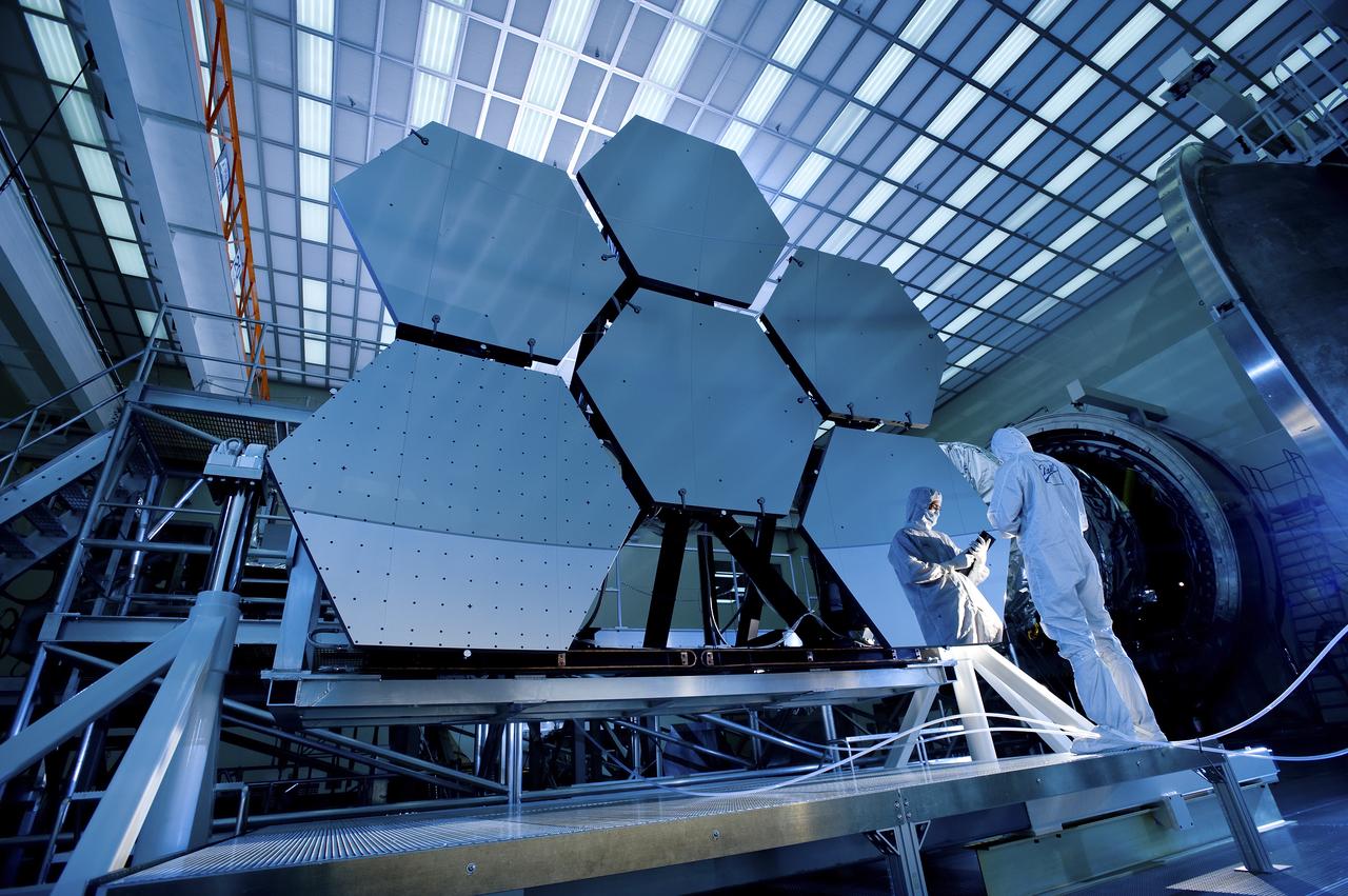
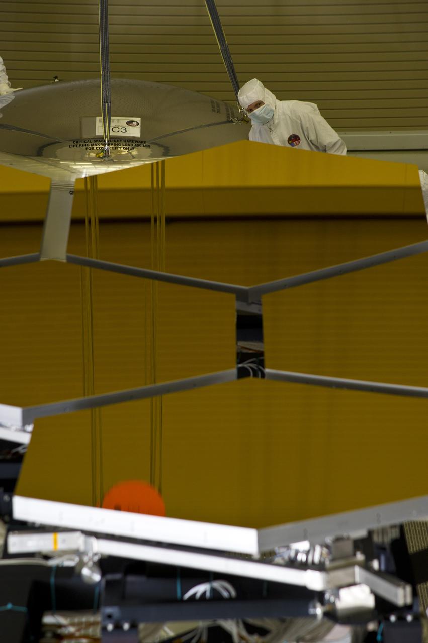
BALL AEROSPACE'S JAKE LEWIS IS REFLECTED IN ONE OF THE MIRRORS ON A JAMES WEBB SPACE TELESCOPE ARRAY THAT WAS IN THE X-RAY AND CRYOGENIC FACILITY FOR TESTING
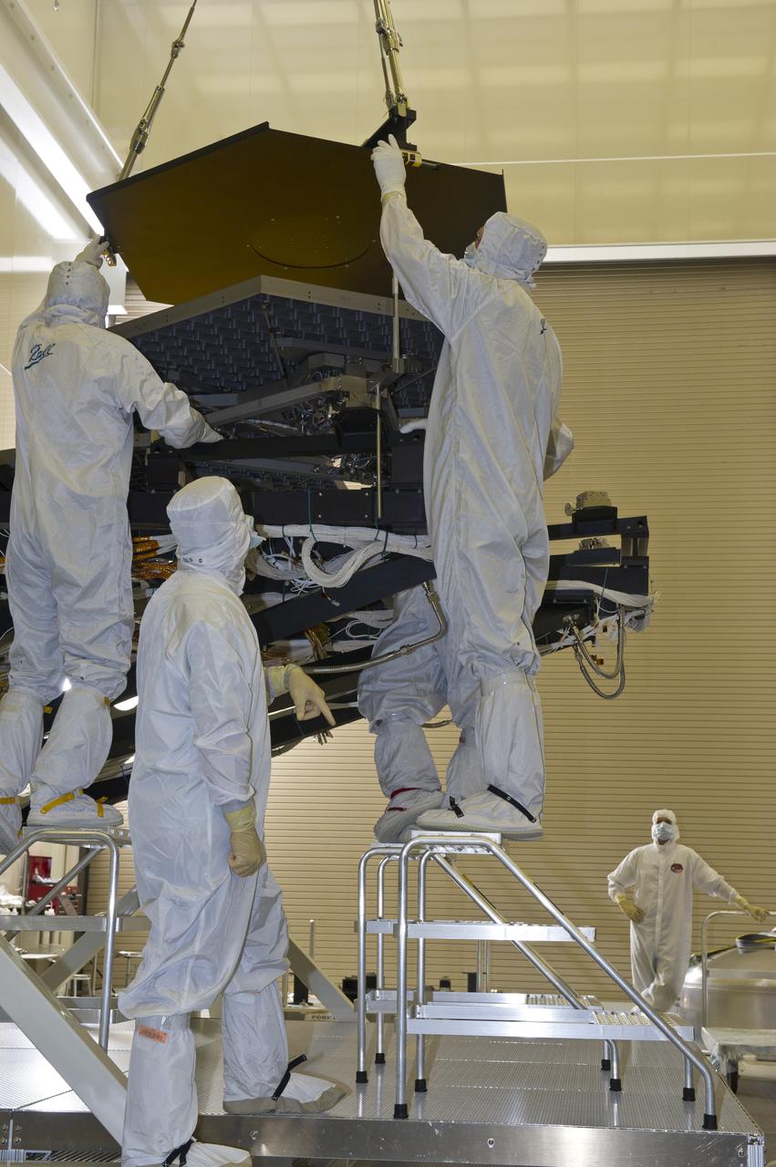
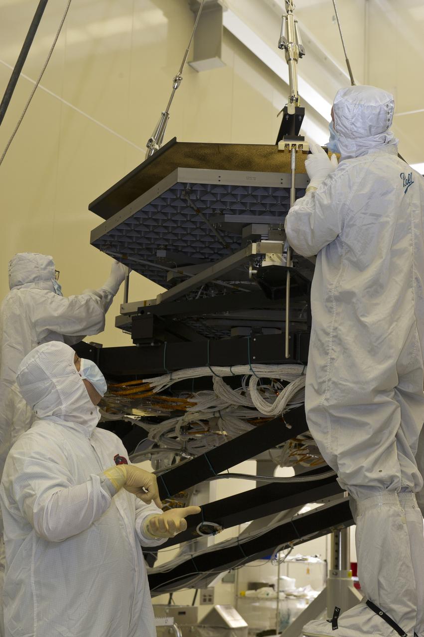
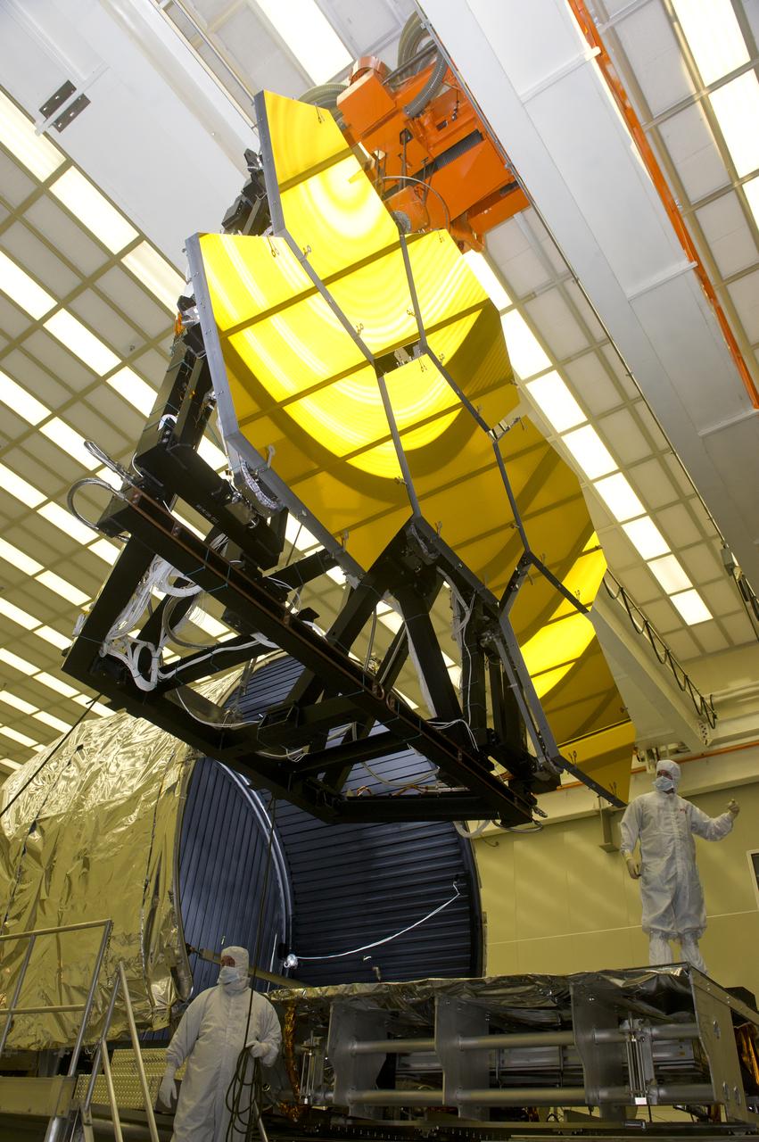
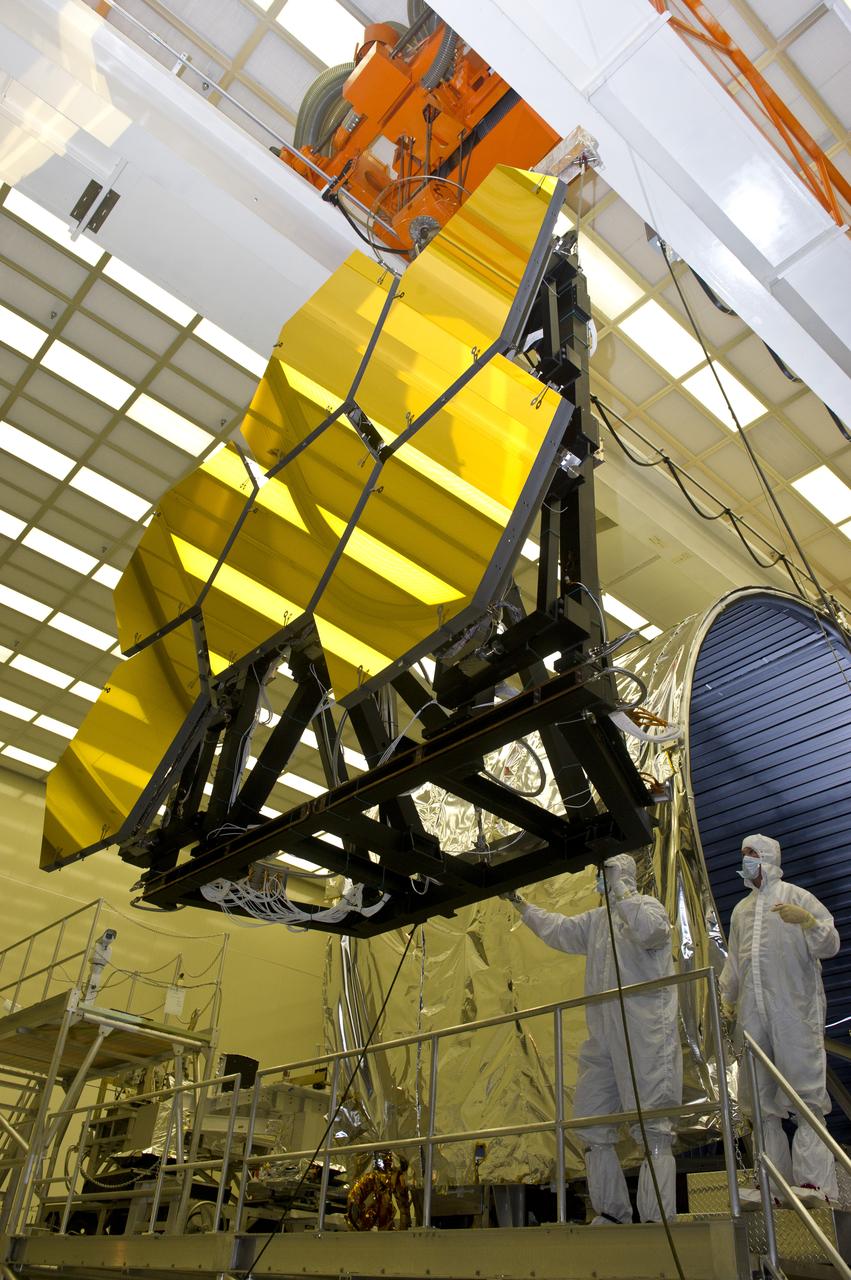
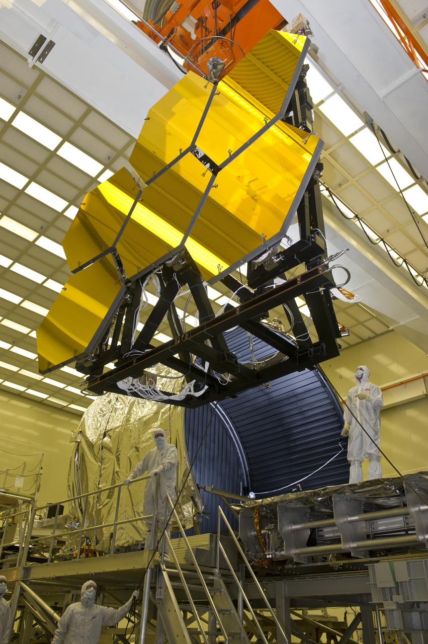
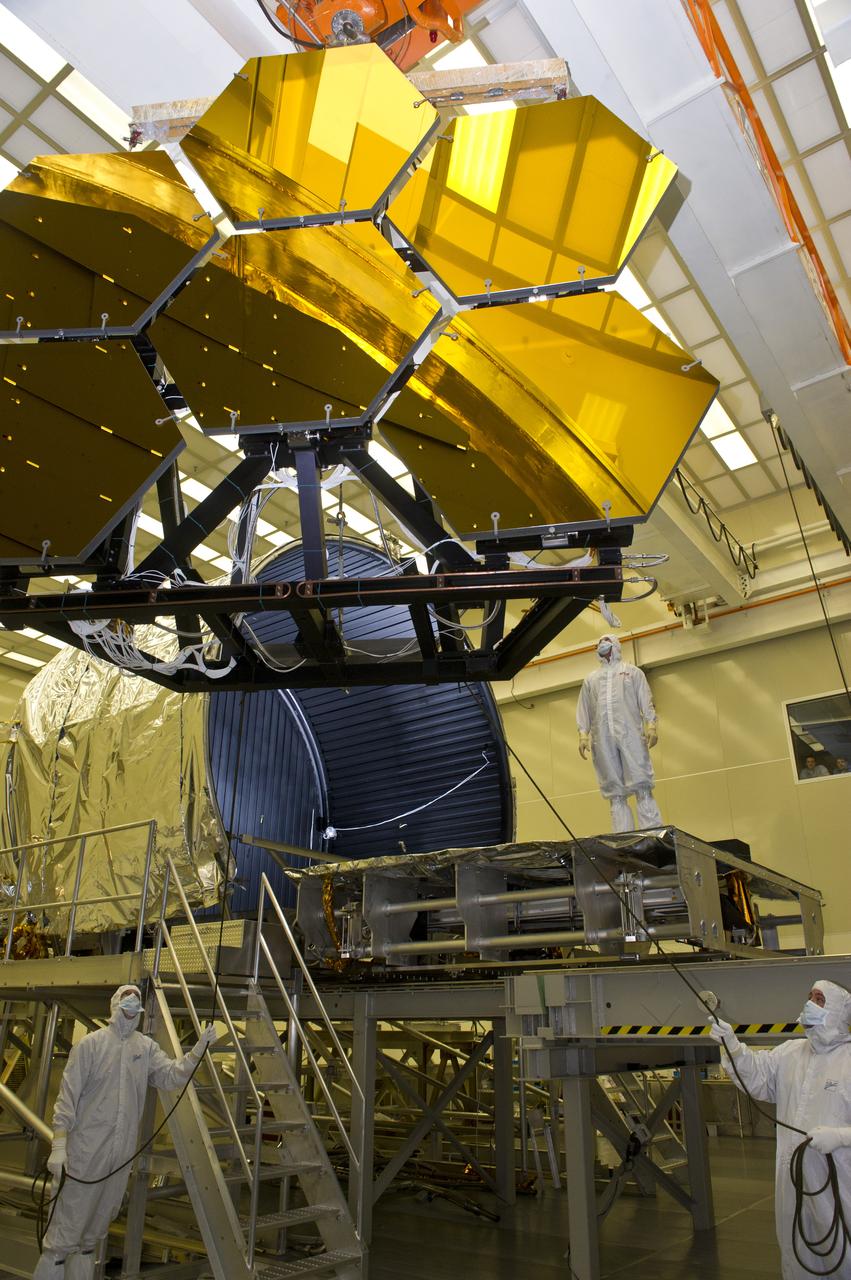
BALL ENGINEERS DISMANTLE ARRAY OF SIX GOLD-PLATED JAMES WEBB SPACE TELESCOPE MIRRORS FOR TRANSPORT TO BALL AEROSPACE AFTER CRYOGENIC TESTING AT MARSHALL'S X-RAY AND CRYOGENIC FACILITY.
BALL ENGINEERS DISMANTLE ARRAY OF SIX GOLD-PLATED JAMES WEBB SPACE TELESCOPE MIRRORS FOR TRANSPORT TO BALL AEROSPACE AFTER CRYOGENIC TESTING AT MARSHALL'S X-RAY AND CRYOGENIC FACILITY.
BALL ENGINEERS DISMANTLE ARRAY OF SIX GOLD-PLATED JAMES WEBB SPACE TELESCOPE MIRRORS FOR TRANSPORT TO BALL AEROSPACE AFTER CRYOGENIC TESTING AT MARSHALL'S X-RAY AND CRYOGENIC FACILITY.
BALL ENGINEERS DISMANTLE ARRAY OF SIX GOLD-PLATED JAMES WEBB SPACE TELESCOPE MIRRORS FOR TRANSPORT TO BALL AEROSPACE AFTER CRYOGENIC TESTING AT MARSHALL'S X-RAY AND CRYOGENIC FACILITY.
BALL ENGINEERS DISMANTLE ARRAY OF SIX GOLD-PLATED JAMES WEBB SPACE TELESCOPE MIRRORS FOR TRANSPORT TO BALL AEROSPACE AFTER CRYOGENIC TESTING AT MARSHALL'S X-RAY AND CRYOGENIC FACILITY.
BALL ENGINEERS DISMANTLE ARRAY OF SIX GOLD-PLATED JAMES WEBB SPACE TELESCOPE MIRRORS FOR TRANSPORT TO BALL AEROSPACE AFTER CRYOGENIC TESTING AT MARSHALL'S X-RAY AND CRYOGENIC FACILITY.
Scientists at Marshall's Adaptive Optics Lab demonstrate the Wave Front Sensor alignment using the Phased Array Mirror Extendible Large Aperture (PAMELA) optics adjustment. The primary objective of the PAMELA project is to develop methods for aligning and controlling adaptive optics segmented mirror systems. These systems can be used to acquire or project light energy. The Next Generation Space Telescope is an example of an energy acquisition system that will employ segmented mirrors. Light projection systems can also be used for power beaming and orbital debris removal. All segmented optical systems must be adjusted to provide maximum performance. PAMELA is an on going project that NASA is utilizing to investigate various methods for maximizing system performance.
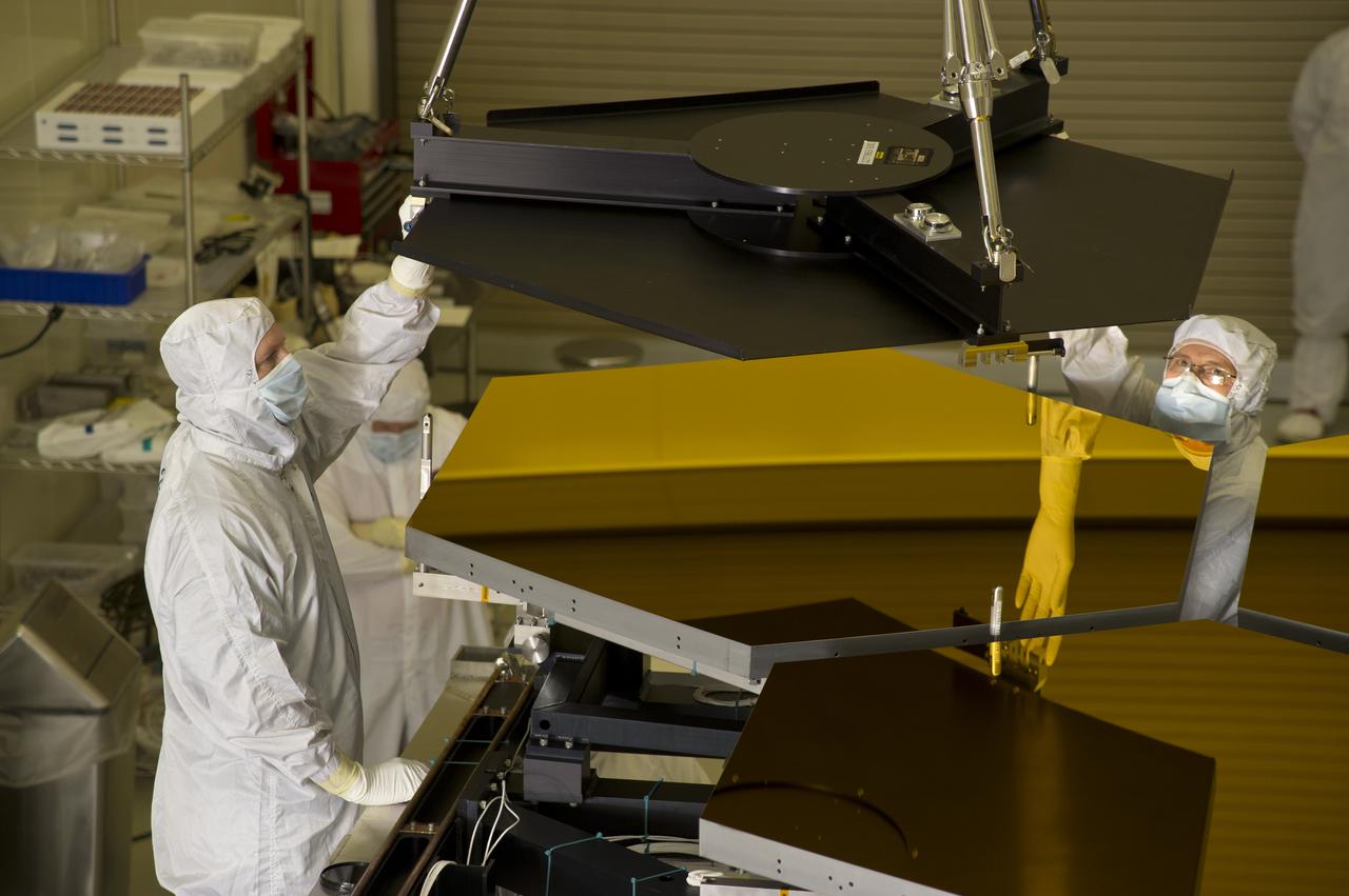
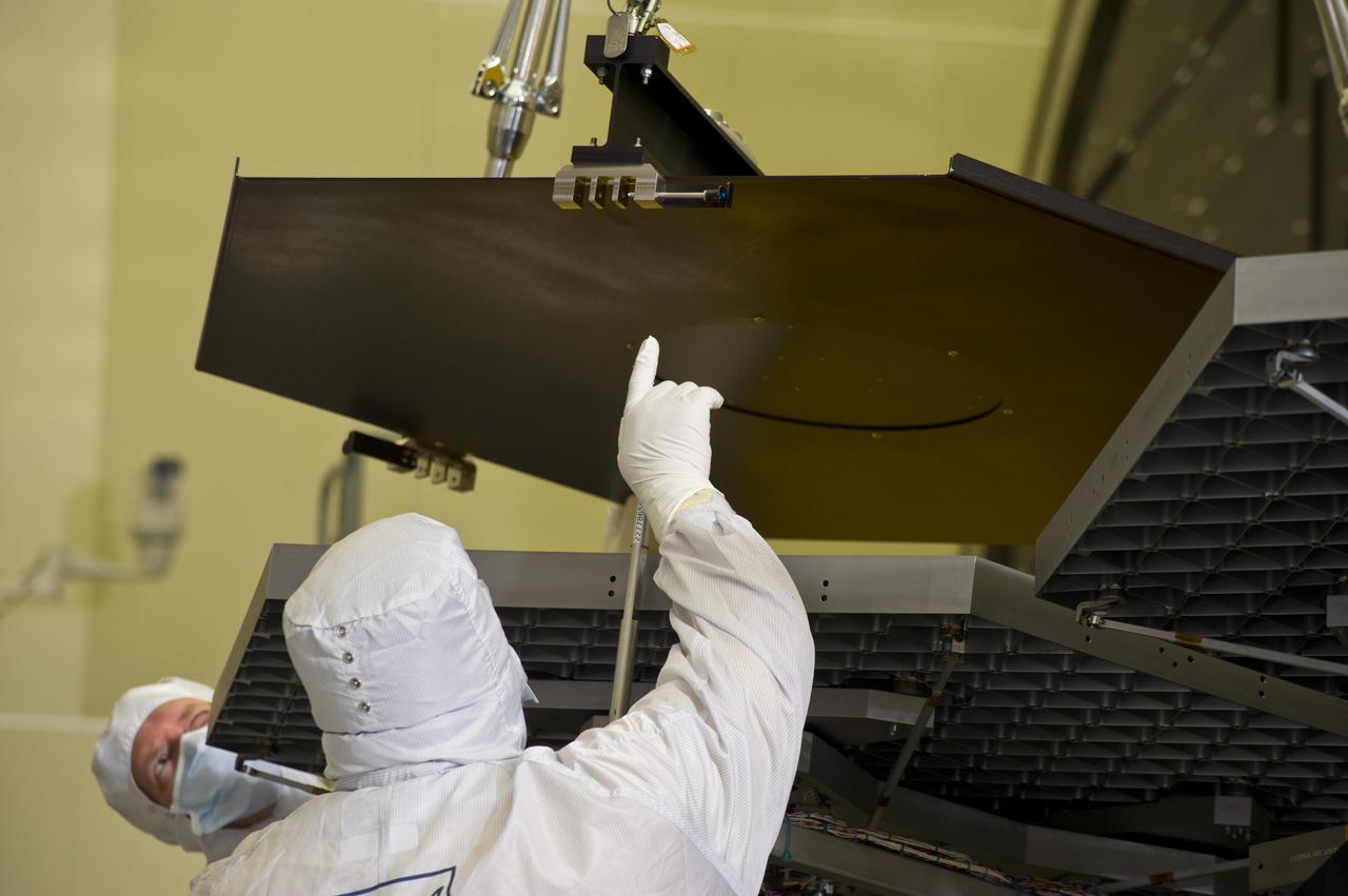
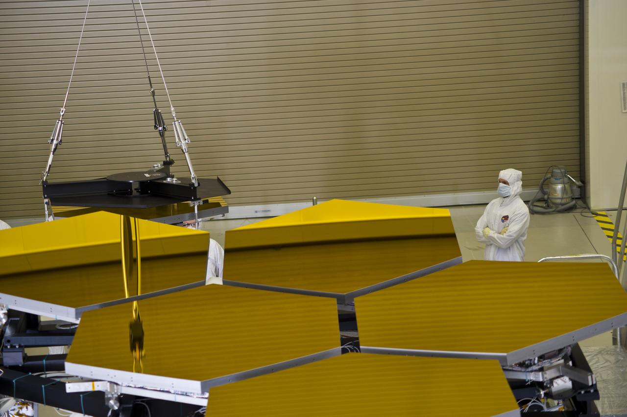
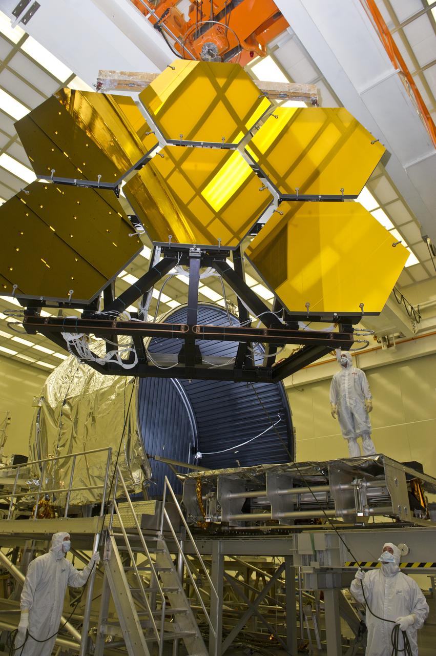
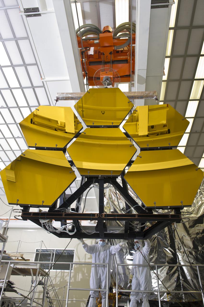
BALL AEROSPACE ENGINEER DAVE CHANEY, (L), AND MARSHALL ENGINEER HARLAN HAIGHT, (R), GUIDE ARRAY OF SIX GOLD-PLATED JAMES WEBB SPACE TELESCOPE MIRRORS AFTER FINAL ACCEPTANCE TESTING AT MARSHALL'S X-RAY AND CRYOGENIC FACILITY
BALL AEROSPACE ENGINEER DAVE CHANEY, (L), AND MARSHALL ENGINEER HARLAN HAIGHT, (R), GUIDE ARRAY OF SIX GOLD-PLATED JAMES WEBB SPACE TELESCOPE MIRRORS AFTER FINAL ACCEPTANCE TESTING AT MARSHALL'S X-RAY AND CRYOGENIC FACILITY
BALL AEROSPACE ENGINEER DAVE CHANEY, (L), AND MARSHALL ENGINEER HARLAN HAIGHT, (R), GUIDE ARRAY OF SIX GOLD-PLATED JAMES WEBB SPACE TELESCOPE MIRRORS AFTER FINAL ACCEPTANCE TESTING AT MARSHALL'S X-RAY AND CRYOGENIC FACILITY
BALL AEROSPACE ENGINEER DAVE CHANEY, (L), AND MARSHALL ENGINEER HARLAN HAIGHT, (R), GUIDE ARRAY OF SIX GOLD-PLATED JAMES WEBB SPACE TELESCOPE MIRRORS AFTER FINAL ACCEPTANCE TESTING AT MARSHALL'S X-RAY AND CRYOGENIC FACILITY
BALL AEROSPACE ENGINEER DAVE CHANEY, (L), AND MARSHALL ENGINEER HARLAN HAIGHT, (R), GUIDE ARRAY OF SIX GOLD-PLATED JAMES WEBB SPACE TELESCOPE MIRRORS AFTER FINAL ACCEPTANCE TESTING AT MARSHALL'S X-RAY AND CRYOGENIC FACILITY
BALL AEROSPACE ENGINEER DAVE CHANEY, (L), AND MARSHALL ENGINEER HARLAN HAIGHT, (R), GUIDE ARRAY OF SIX GOLD-PLATED JAMES WEBB SPACE TELESCOPE MIRRORS AFTER FINAL ACCEPTANCE TESTING AT MARSHALL'S X-RAY AND CRYOGENIC FACILITY
BALL AEROSPACE ENGINEER DAVE CHANEY, (L), AND MARSHALL ENGINEER HARLAN HAIGHT, (R), GUIDE ARRAY OF SIX GOLD-PLATED JAMES WEBB SPACE TELESCOPE MIRRORS AFTER FINAL ACCEPTANCE TESTING AT MARSHALL'S X-RAY AND CRYOGENIC FACILITY
BALL AEROSPACE ENGINEER DAVE CHANEY, (L), AND MARSHALL ENGINEER HARLAN HAIGHT, (R), GUIDE ARRAY OF SIX GOLD-PLATED JAMES WEBB SPACE TELESCOPE MIRRORS AFTER FINAL ACCEPTANCE TESTING AT MARSHALL'S X-RAY AND CRYOGENIC FACILITY
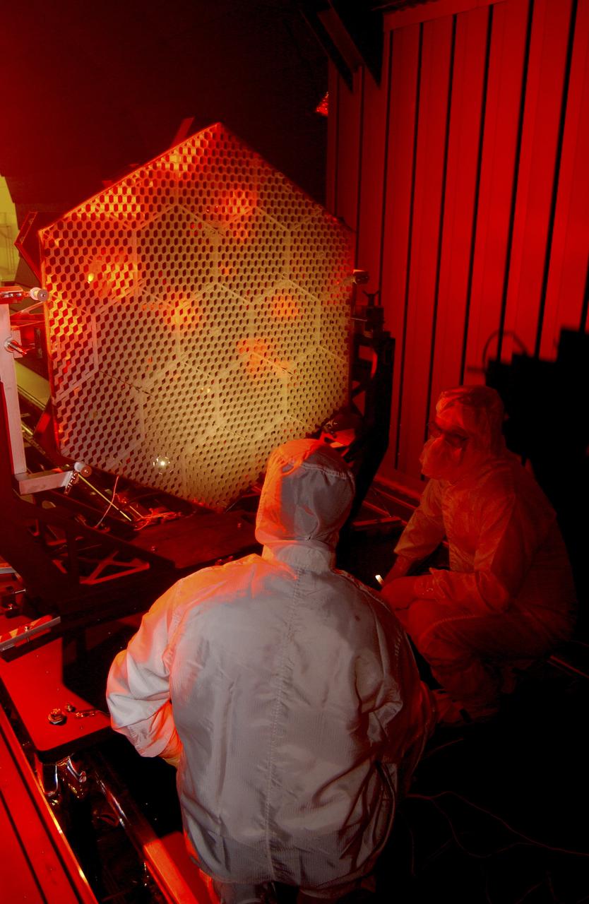
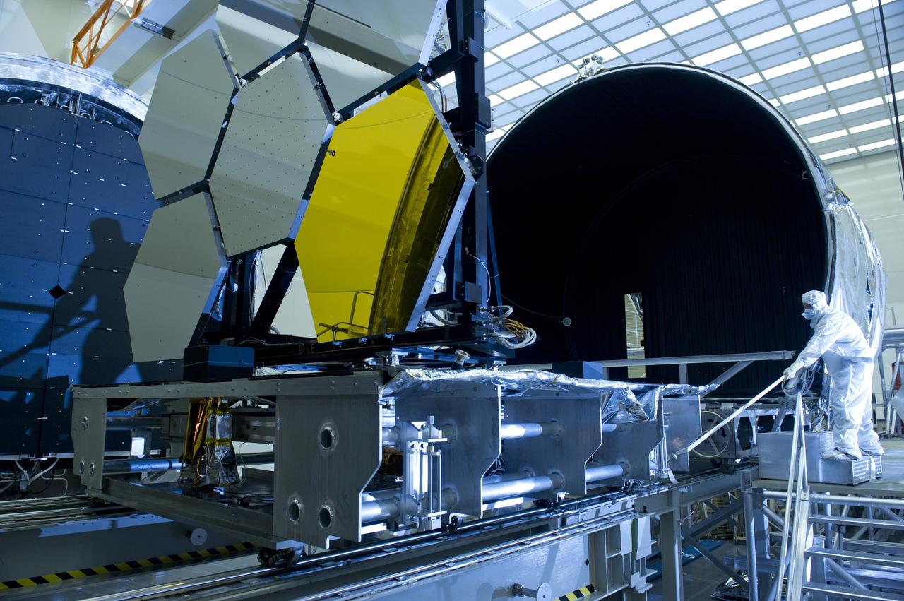
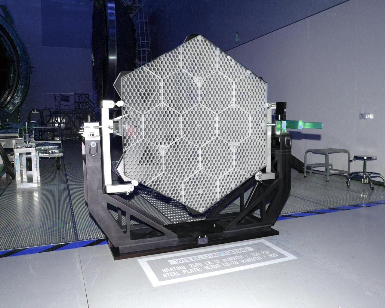
The Eastman-Kodak mirror assembly is being tested for the James Webb Space Telescope (JWST) project at the X-Ray Calibration Facility at Marshall Space Flight Center (MSFC). In this photo, one of many segments of the mirror assembly is being set up inside the 24-ft vacuum chamber where it will undergo x-ray calibration tests. MSFC is supporting Goddard Space Flight Center (GSFC) in developing the JWST by taking numerous measurements to predict its future performance. The tests are conducted in a vacuum chamber cooled to approximate the super cold temperatures found in space. During its 27 years of operation, the facility has performed testing in support of a wide array of projects, including the Hubble Space Telescope (HST), Solar A, Chandra technology development, Chandra High Resolution Mirror Assembly and science instruments, Constellation X-Ray Mission, and Solar X-Ray Imager, currently operating on a Geostationary Operational Environment Satellite. The JWST is NASA's next generation space telescope, a successor to the Hubble Space Telescope, named in honor of NASA's second administrator, James E. Webb. It is scheduled for launch in 2010 aboard an expendable launch vehicle. It will take about 3 months for the spacecraft to reach its destination, an orbit of 940,000 miles in space.
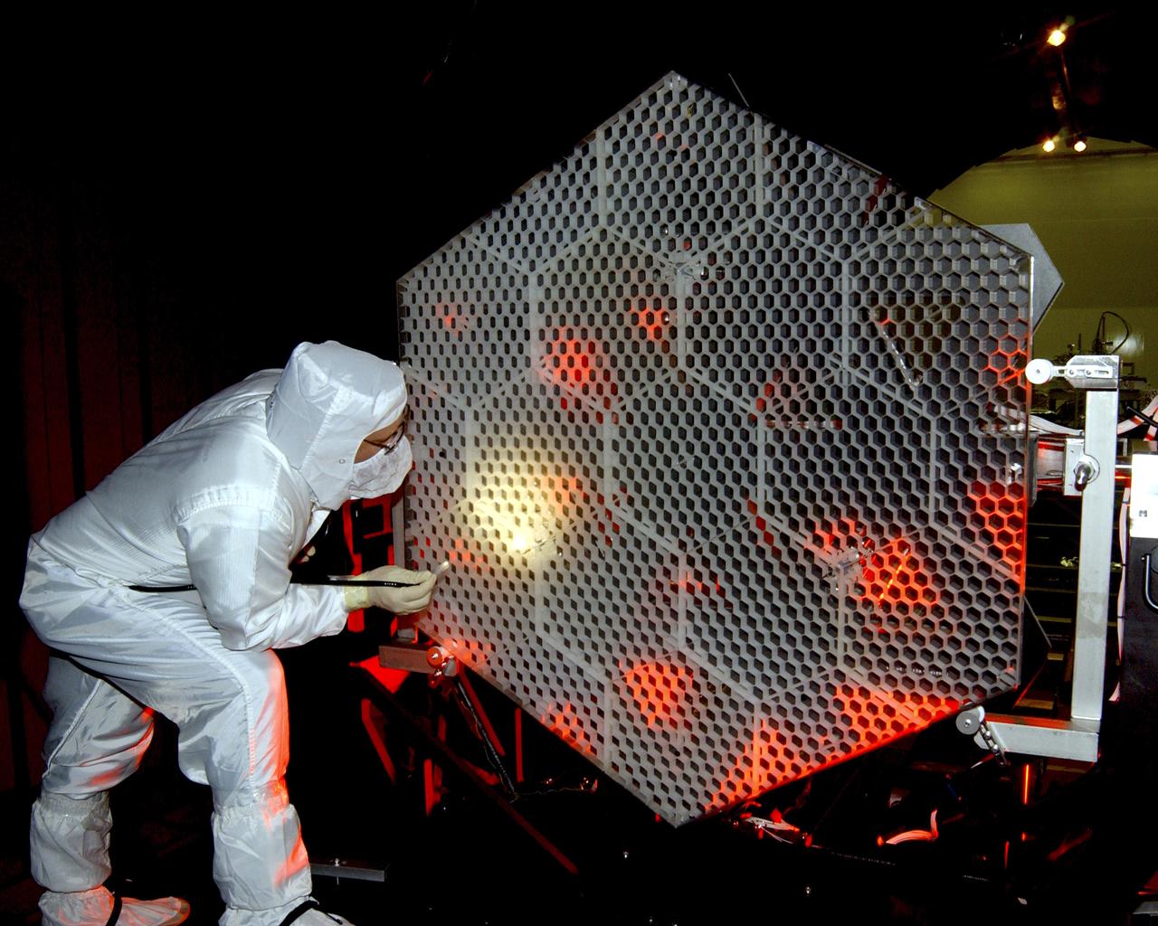
The Eastman-Kodak mirror assembly is being tested for the James Webb Space Telescope (JWST) project at the X-Ray Calibration Facility at Marshall Space Flight Center (MSFC). In this photo, an MSFC employee is inspecting one of many segments of the mirror assembly for flaws. MSFC is supporting Goddard Space Flight Center (GSFC) in developing the JWST by taking numerous measurements to predict its future performance. The tests are conducted in a vacuum chamber cooled to approximate the super cold temperatures found in space. During its 27 years of operation, the facility has performed testing in support of a wide array of projects, including the Hubble Space Telescope (HST), Solar A, Chandra technology development, Chandra High Resolution Mirror Assembly and science instruments, Constellation X-Ray Mission, and Solar X-Ray Imager, currently operating on a Geostationary Operational Environment Satellite. The JWST is NASA's next generation space telescope, a successor to the Hubble Space Telescope, named in honor of NASA's second administrator, James E. Webb. It is scheduled for launch in 2010 aboard an expendable launch vehicle. It will take about 3 months for the spacecraft to reach its destination, an orbit of 940,000 miles in space.
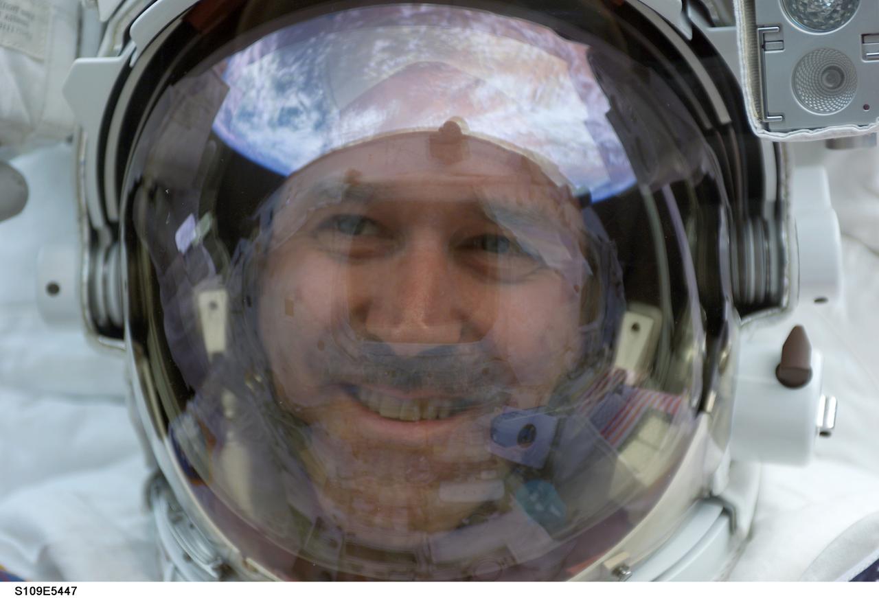
STS109-E-5447 (4 March 2002) --- Astronaut John M. Grunsfeld, payload commander, peers into the crew cabin of the Space Shuttle Columbia during the first STS-109 extravehicular activity (EVA-1) on March 4, 2002. Grunsfeld's helmet visor displays a mirrored image of the Earth's hemisphere. Astronauts Grunsfeld and Richard M. Linnehan replaced the starboard solar array on the Hubble Space Telescope (HST) on the first of five scheduled STS-109 space walks. The image was recorded with a digital still camera by a crewmate on shuttle's aft flight deck.
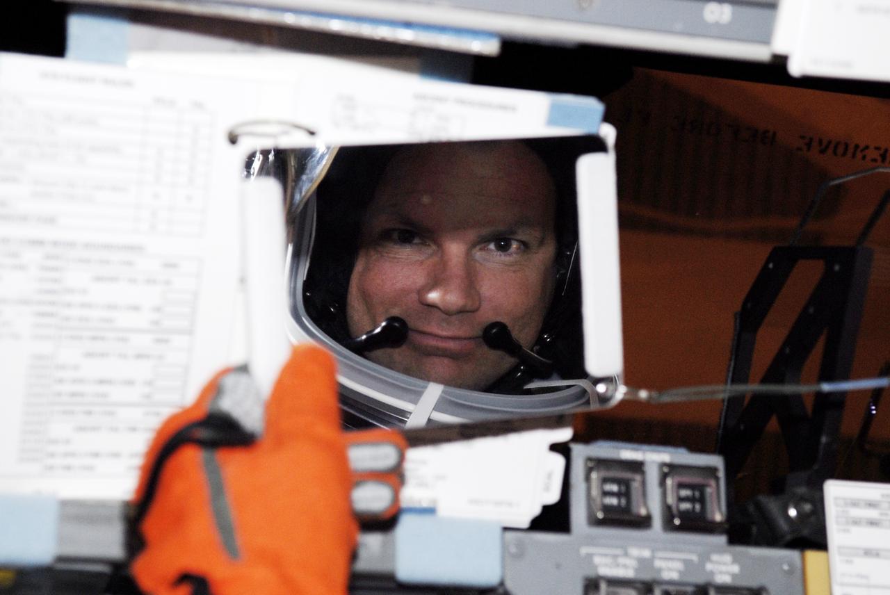
CAPE CANAVERAL, Fla. – Seated in space shuttle Discovery on Launch Pad 39A at NASA's Kennedy Space Center in Florida, STS-119 Pilot Tony Antonelli checks a mirror as he prepares for a simulated launch countdown as part of the prelaunch preparation known as Terminal Countdown Demonstration Test. The TCDT also includes equipment familiarization. Discovery is targeted to launch on the STS-119 mission Feb. 12. During the 14-day mission, the crew will install the S6 truss segment and solar arrays to the starboard side of the International Space Station, completing the station's truss, or backbone. Photo credit: NASA/Kim Shiflett
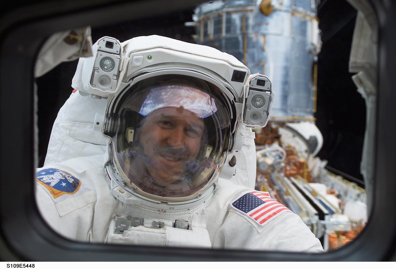
STS109-E-5448 (4 March 2002) --- Astronaut John M. Grunsfeld, payload commander, peers into the crew cabin of the Space Shuttle Columbia during the first STS-109 extravehicular activity (EVA-1) on March 4, 2002. Grunsfeld's helmet visor displays a mirrored image of the Earth's hemisphere. Astronauts Grunsfeld and Richard M. Linnehan replaced the starboard solar array on the Hubble Space Telescope (HST) on the first of five scheduled STS-109 space walks. The lower portion of the giant telescope can be seen over Grunsfeld's left shoulder. The image was recorded with a digital still camera by a crewmate on shuttle's aft flight deck.
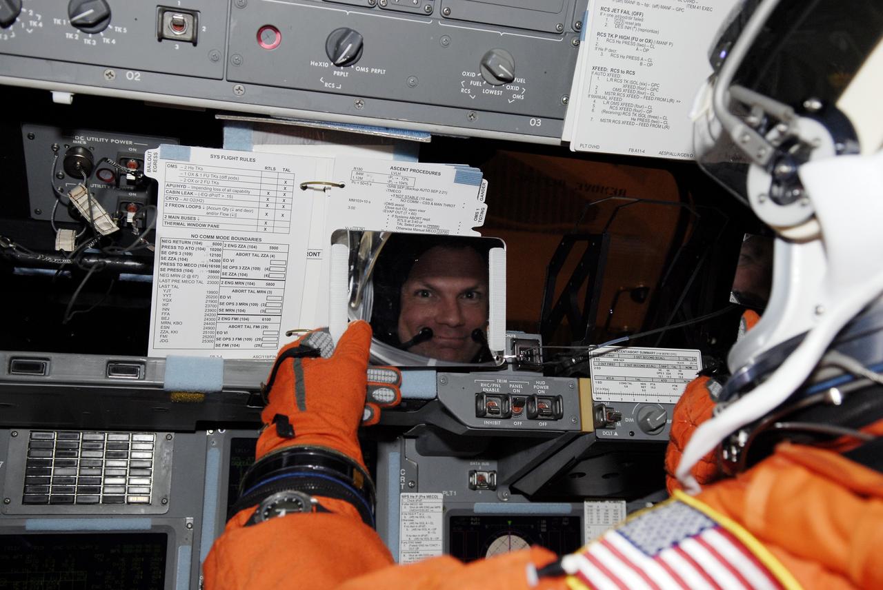
CAPE CANAVERAL, Fla. – Seated in space shuttle Discovery on Launch Pad 39A at NASA's Kennedy Space Center in Florida, STS-119 Pilot Tony Antonelli checks a mirror as he prepares for a simulated launch countdown as part of the prelaunch preparation known as Terminal Countdown Demonstration Test. The TCDT also includes equipment familiarization. Discovery is targeted to launch on the STS-119 mission Feb. 12. During the 14-day mission, the crew will install the S6 truss segment and solar arrays to the starboard side of the International Space Station, completing the station's truss, or backbone. Photo credit: NASA/Kim Shiflett
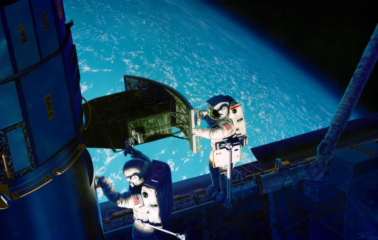
S93-48826 (November 1993) --- This artist's rendition of the 1993 Hubble Space Telescope (HST) servicing mission shows astronauts installing the new Wide Field/Planetary Camera (WF/PC 2). The instruments to replace the original camera and contains corrective optics that compensate for the telescope's flawed primary mirror. During the 11-plus day mission, astronauts are also scheduled to install the Corrective Optics Space Telescope Axial Replacement (COSTAR) -- an optics package that focuses and routes light to the other three instruments aboard the observatory -- a new set of solar array panels, and other hardware and components. The artwork was done for JPL by Paul Hudson.
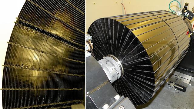
This photo (a frontal view) is of one of many segments of the Eastman-Kodak mirror assembly being tested for the James Webb Space Telescope (JWST) project at the X-Ray Calibration Facility at Marshall Space Flight Center (MSFC). MSFC is supporting Goddard Space Flight Center (GSFC) in developing the JWST by taking numerous measurements to predict its future performance. The tests are conducted in a vacuum chamber cooled to approximate the super cold temperatures found in space. During its 27 years of operation, the facility has performed testing in support of a wide array of projects, including the Hubble Space Telescope (HST), Solar A, Chandra technology development, Chandra High Resolution Mirror Assembly and science instruments, Constellation X-Ray Mission, and Solar X-Ray Imager, currently operating on a Geostationary Operational Environment Satellite. The JWST is NASA's next generation space telescope, a successor to the Hubble Space Telescope, named in honor of NASA's second administrator, James E. Webb. It is scheduled for launch in 2010 aboard an expendable launch vehicle. It will take about 3 months for the spacecraft to reach its destination, an orbit of 940,000 miles in space.
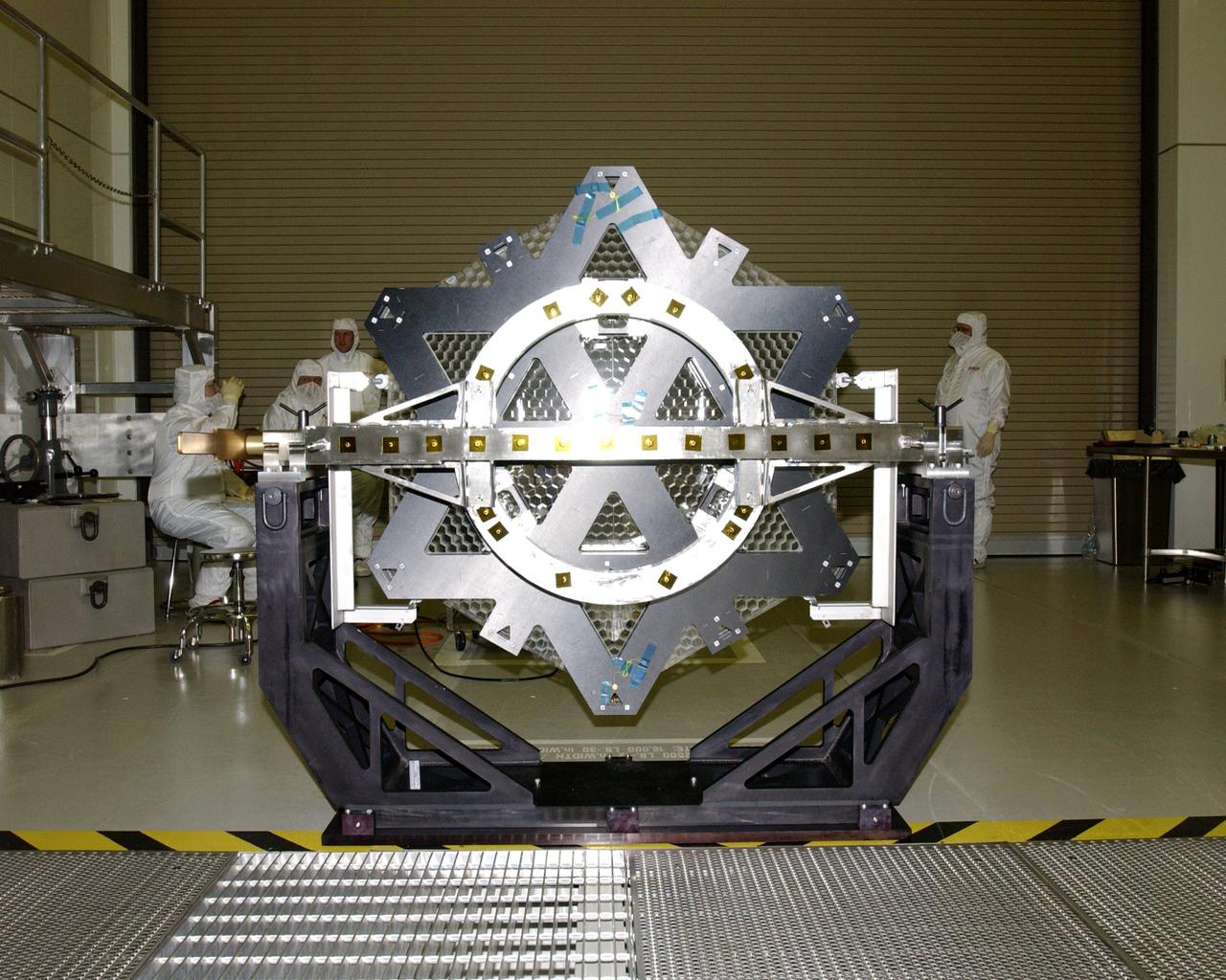
This photo (rear view) is of one of many segments of the Eastman-Kodak mirror assembly being tested for the James Webb Space Telescope (JWST) project at the X-Ray Calibration Facility at Marshall Space Flight Center (MSFC). MSFC is supporting Goddard Space Flight Center (GSFC) in developing the JWST by taking numerous measurements to predict its future performance. The tests are conducted in a vacuum chamber cooled to approximate the super cold temperatures found in space. During its 27 years of operation, the facility has performed testing in support of a wide array of projects, including the Hubble Space Telescope (HST), Solar A, Chandra technology development, Chandra High Resolution Mirror Assembly and science instruments, Constellation X-Ray Mission, and Solar X-Ray Imager, currently operating on a Geostationary Operational Environment Satellite. The JWST is NASA's next generation space telescope, a successor to the Hubble Space Telescope, named in honor of NASA's second administrator, James E. Webb. It is scheduled for launch in 2010 aboard an expendable launch vehicle. It will take about 3 months for the spacecraft to reach its destination, an orbit of 940,000 miles in space.
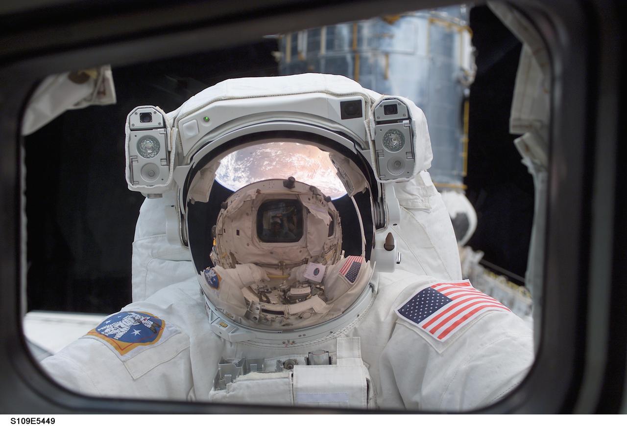
STS109-E-5449 (4 March 2002) --- Astronaut John M. Grunsfeld, payload commander, peers into the crew cabin of the Space Shuttle Columbia during the first STS-109 extravehicular activity (EVA-1) on March 4, 2002. Grunsfeld's helmet visor, with the sunshield now in place, displays mirrored images of the Earth's hemisphere and the Space Shuttle Columbia's aft cabin. The distorted reflection gives the crew cabin a cyclops-like appearance. Astronauts Grunsfeld and Richard M. Linnehan replaced the starboard solar array on the Hubble Space Telescope (HST) on the first of five scheduled STS-109 space walks. The lower portion of the giant telescope can be seen behind the payload commander. The image was recorded with a digital still camera by a crewmate on shuttle's aft flight deck.
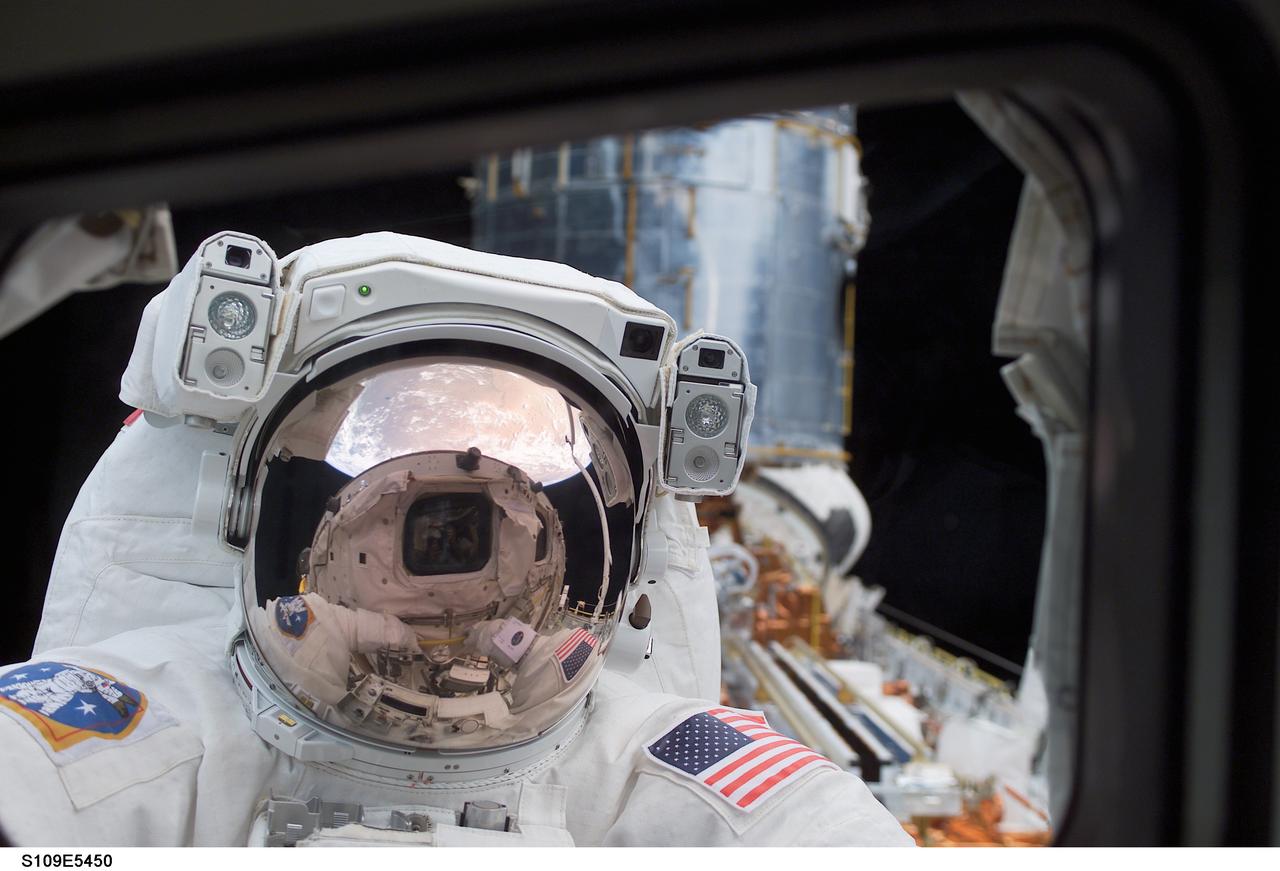
STS109-E-5450 (4 March 2002) --- Astronaut John M. Grunsfeld, payload commander, peers into the crew cabin of the Space Shuttle Columbia during the first STS-109 extravehicular activity (EVA-1) on March 4, 2002. Grunsfeld's helmet visor, with the sunshield now in place, displays mirrored images of the Earth's hemisphere and the Space Shuttle Columbia's aft cabin. The distorted reflection gives the crew cabin a cyclops-like appearance. Astronauts Grunsfeld and Richard M. Linnehan replaced the starboard solar array on the Hubble Space Telescope (HST) on the first of five scheduled STS-109 space walks. The lower portion of the giant telescope can be seen behind the payload commander. The image was recorded with a digital still camera by a crewmate on shuttle's aft flight deck.

NASA Associate Administrator for the Science Mission Directorate Thomas Zurbuchen, left, and Centre National d’Etudes Spatiales (CNES) Chairman and CEO Philippe Baptiste, celebrate after hearing confirmation that the James Webb Space Telescope successfully deployed it’s solar arrays and the telescope had positive power, Saturday, Dec. 25, 2021, in the Jupiter Hall of the Guiana Space Centre in Kourou, French Guiana. The James Webb Space Telescope (sometimes called JWST or Webb) is a large infrared telescope with a 21.3 foot (6.5 meter) primary mirror. The observatory will study every phase of cosmic history—from within our solar system to the most distant observable galaxies in the early universe. Photo Credit: (NASA/Bill Ingalls)
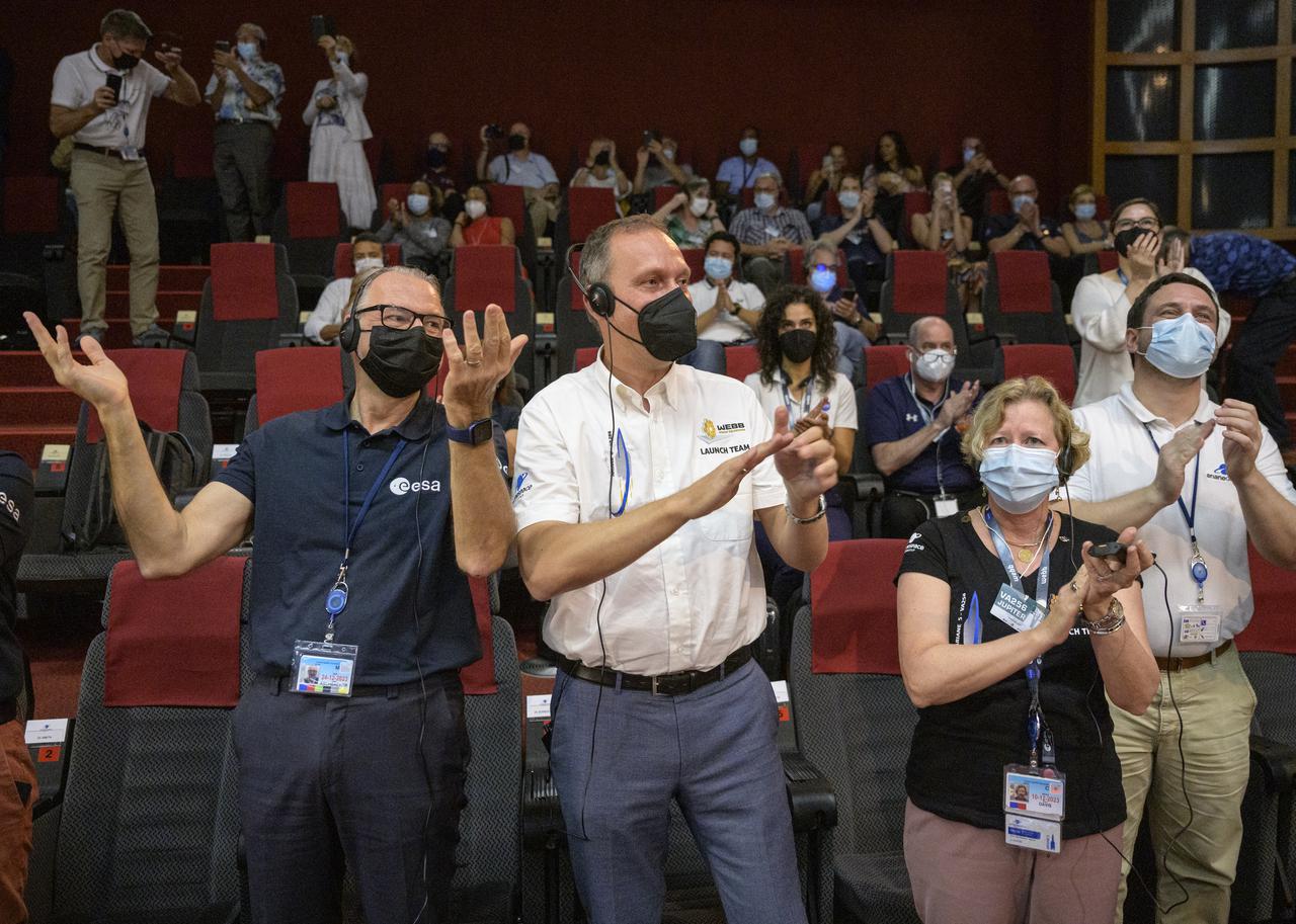
ESA (European Space Agency) Director-General Dr. Josef Aschbacher, left, NASA Associate Administrator for the Science Mission Directorate Thomas Zurbuchen, and NASA James Webb Space Telescope Program Manager Jeanne Davis, celebrate after hearing confirmation that the James Webb Space Telescope successfully deployed it’s solar arrays and the telescope had positive power, Saturday, Dec. 25, 2021, in the Jupiter Hall of the Guiana Space Centre in Kourou, French Guiana. The James Webb Space Telescope (sometimes called JWST or Webb) is a large infrared telescope with a 21.3 foot (6.5 meter) primary mirror. The observatory will study every phase of cosmic history—from within our solar system to the most distant observable galaxies in the early universe. Photo Credit: (NASA/Bill Ingalls)

Thousands of galaxies flood this near-infrared image of galaxy cluster SMACS 0723. High-resolution imaging from NASA’s James Webb Space Telescope combined with a natural effect known as gravitational lensing made this finely detailed image possible. First, focus on the galaxies responsible for the lensing: the bright white elliptical galaxy at the center of the image and smaller white galaxies throughout the image. Bound together by gravity in a galaxy cluster, they are bending the light from galaxies that appear in the vast distances behind them. The combined mass of the galaxies and dark matter act as a cosmic telescope, creating magnified, contorted, and sometimes mirrored images of individual galaxies. Clear examples of mirroring are found in the prominent orange arcs to the left and right of the brightest cluster galaxy. These are lensed galaxies – each individual galaxy is shown twice in one arc. Webb’s image has fully revealed their bright cores, which are filled with stars, along with orange star clusters along their edges. Not all galaxies in this field are mirrored – some are stretched. Others appear scattered by interactions with other galaxies, leaving trails of stars behind them. Webb has refined the level of detail we can observe throughout this field. Very diffuse galaxies appear like collections of loosely bound dandelion seeds aloft in a breeze. Individual “pods” of star formation practically bloom within some of the most distant galaxies – the clearest, most detailed views of star clusters in the early universe so far. One galaxy speckled with star clusters appears near the bottom end of the bright central star’s vertical diffraction spike – just to the right of a long orange arc. The long, thin ladybug-like galaxy is flecked with pockets of star formation. Draw a line between its “wings” to roughly match up its star clusters, mirrored top to bottom. Because this galaxy is so magnified and its individual star clusters are so crisp, researchers will be able to study it in exquisite detail, which wasn’t previously possible for galaxies this distant. The galaxies in this scene that are farthest away – the tiniest galaxies that are located well behind the cluster – look nothing like the spiral and elliptical galaxies observed in the local universe. They are much clumpier and more irregular. Webb’s highly detailed image may help researchers measure the ages and masses of star clusters within these distant galaxies. This might lead to more accurate models of galaxies that existed at cosmic “spring,” when galaxies were sprouting tiny “buds” of new growth, actively interacting and merging, and had yet to develop into larger spirals. Ultimately, Webb’s upcoming observations will help astronomers better understand how galaxies form and grow in the early universe. NIRCam was built by a team at the University of Arizona and Lockheed Martin’s Advanced Technology Center. For a full array of Webb’s first images and spectra, including downloadable files, please visit: https://webbtelescope.org/news/first-images
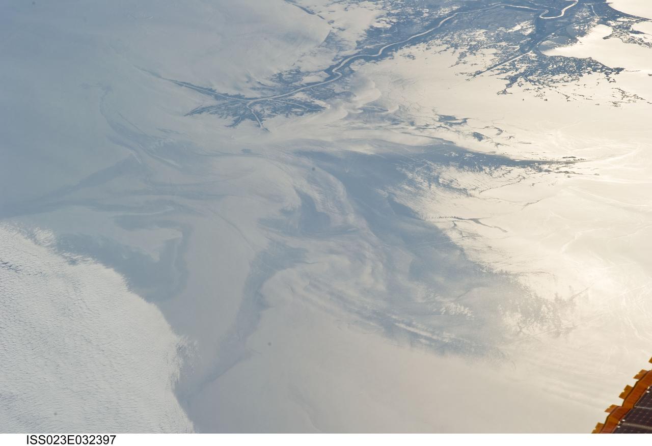
ISS023-E-032397 (4 May 2010) --- The Gulf of Mexico oil spill is featured in this image photographed by an Expedition 23 crew member on the International Space Station. On April 20, 2010 the oil rig Deepwater Horizon suffered an explosion and sank two days later. Shortly thereafter oil began leaking into the Gulf of Mexico from ruptured pipes as safety cutoff mechanisms failed to operate. Automated nadir-viewing orbital NASA sensors have been tracking the growth of the oil spill as it has spread towards the northern Gulf Coast. This detailed photograph provides a different viewing perspective on the ongoing event. The image is oblique, meaning that it was taken with a sideways viewing angle from the space station, rather than the ?straight down? or nadir view typical of automated satellite sensors. The view is towards the west; the ISS was located over the eastern edge of the Gulf of Mexico when the image was taken. The Mississippi River Delta and nearby Louisiana coast (top) appear dark in the sunglint that illuminates most of the image. This phenomenon is caused by sunlight reflecting off the water surface ? much like a mirror ? directly back towards the astronaut observer onboard the orbital complex. The sunglint improves the identification of the oil spill (colored dark to light gray) which is creating a different water texture, and therefore a contrast, between the smooth and rougher water of the reflective ocean surface (colored silver to white). Wind and water current patterns have modified the oil spill?s original shape into streamers and elongated masses. Efforts are ongoing to contain the spill and protect fragile coastal ecosystems and habitats such as the Chandeleur Islands (right center). Other features visible in the image include a solid field of low cloud cover at the lower left corner of the image. A part of one of the ISS solar arrays is visible at lower right. Wave patterns at lower right are most likely caused by tidal effects.
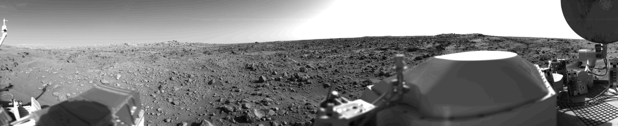
First panoramic view by NASA's Viking 1 from the surface of Mars. The out of focus spacecraft component toward left center is the housing for the Viking sample arm, which is not yet deployed. Parallel lines in the sky are an artifact and are not real features. However, the change of brightness from horizon towards zenith and towards the right (west) is accurately reflected in this picture, taken in late Martian afternoon. At the horizon to the left is a plateau-like prominence much brighter than the foreground material between the rocks. The horizon features are approximately three kilometers (1.8 miles) away. At left is a collection of fine-grained material reminiscent of sand dunes. The dark sinuous markings in left foreground are of unknown origin. Some unidentified shapes can be perceived on the hilly eminence at the horizon towards the right. A horizontal cloud stratum can be made out halfway from the horizon to the top of the picture. At left is seen the low gain antenna for receipt of commands from the Earth. The projections on or near the horizon may represent the rims distant impact craters. In right foreground are color charts for Lander camera calibration, a mirror for the Viking magnetic properties experiment and part of a grid on the top of the Lander body. At upper right is the high gain dish antenna for direct communication between landed spacecraft and Earth. Toward the right edge is an array of smooth fine-grained material which shows some hint of ripple structure and may be the beginning of a large dune field off to the right of the picture, which joins with dunes seen at the top left in this 300 degree panoramic view. Some of the rocks appear to be undercut on one side and partially buried by drifting sand on the other. http://photojournal.jpl.nasa.gov/catalog/PIA00383
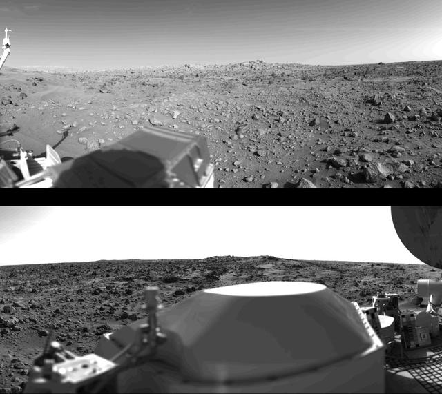
First panoramic view by Viking 1 from the surface of Mars. (Top): The out-of-focus spacecraft component toward left center is the housing for the Viking sample arm, which is not yet deployed. Parallel lines in the sky are an artifact and are not real features. However, the change of brightness from horizon towards zenith and towards the right (west) is accurately reflected in this picture, taken in late Martian afternoon. At the horizon to the left is a plateau-like prominence much brighter than the foreground material between the rocks. The horizon features are approximately three kilometers (1.8 miles) away. At left is a collection of fine-grained material reminiscent of sand dunes. The dark sinuous markings in left foreground are of unknown origin. Some unidentified shapes can be perceived on the hilly eminence at the horizon towards the right. Patches of bright sand can be discerned among the rocks and boulders in middle distance. In right fore-ground are two peculiarly shaped rocks which may possibly be ventifacts produced by wind abrasion on Mars. A horizontal cloud stratum can be made out halfway from the horizon to the top of the picture. (Bottom): At left is seen the low gain antenna for receipt of commands from the Earth. The projections on or near the horizon may represent the rims distant impact craters. In right foreground are color charts for Lander camera calibration, a mirror for the Viking magnetic properties experiment and part of a grid on the top of the Lander body. At upper right is the high-gain dish antenna for direct communication between landed space-craft and Earth. Toward the right edge is an array of smooth fine-grained material which shows some hint of ripple structure and may be the beginning of a large dune field off to the right of the picture, which joins with dunes seen at the top left in this 300 panoramic view. Some of the rocks appear to be undercut on one side and partially buried by drifting sand on the other. http://photojournal.jpl.nasa.gov/catalog/PIA00382