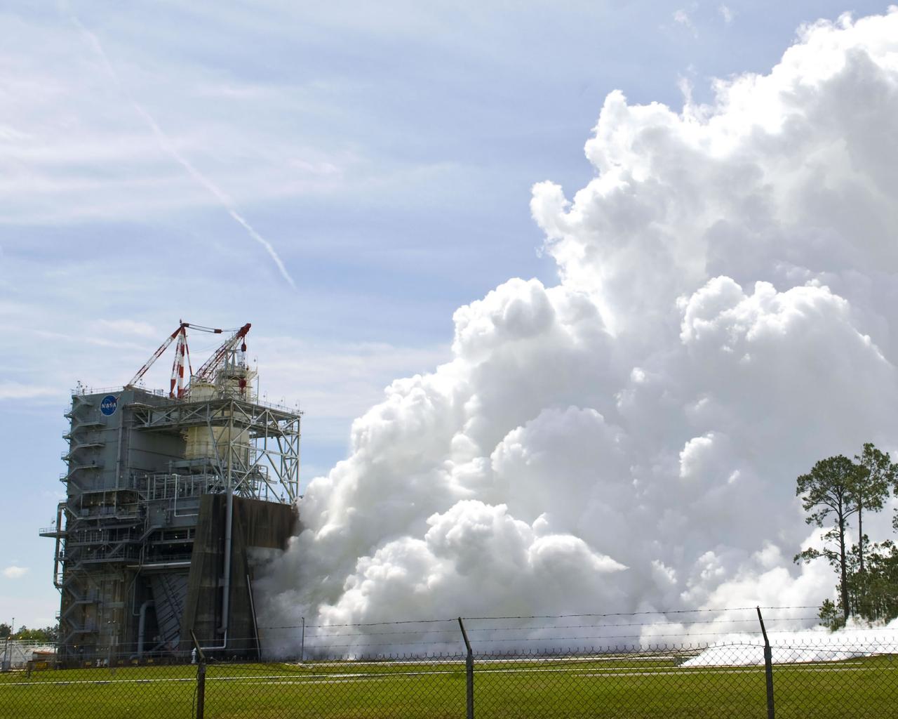
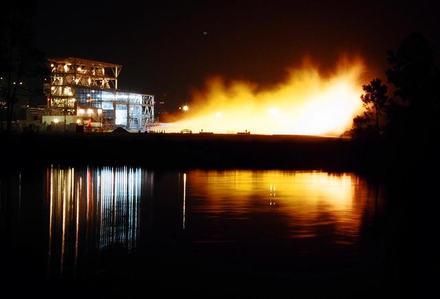
Stennis engineers conduct a test of a space shuttle main engine on March 30, 2009.
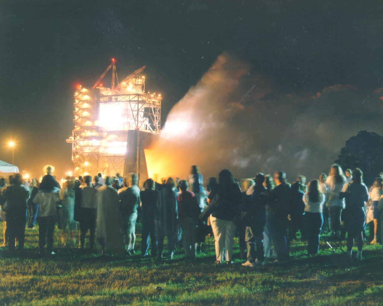
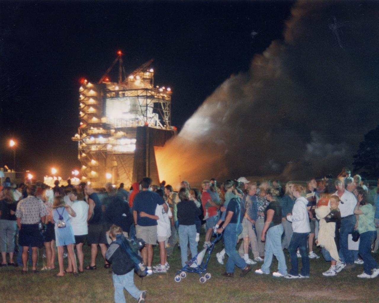
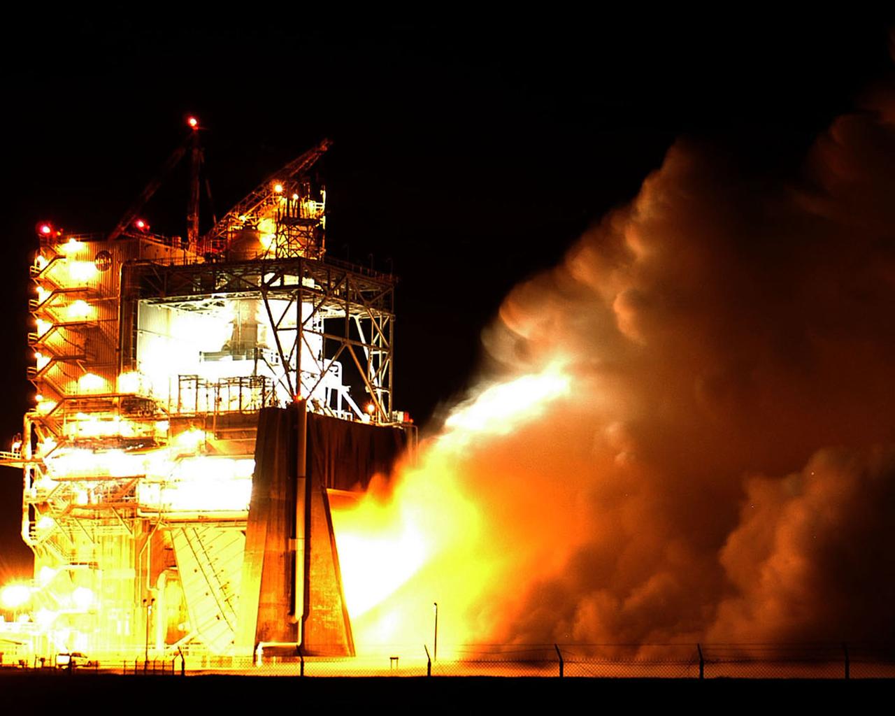
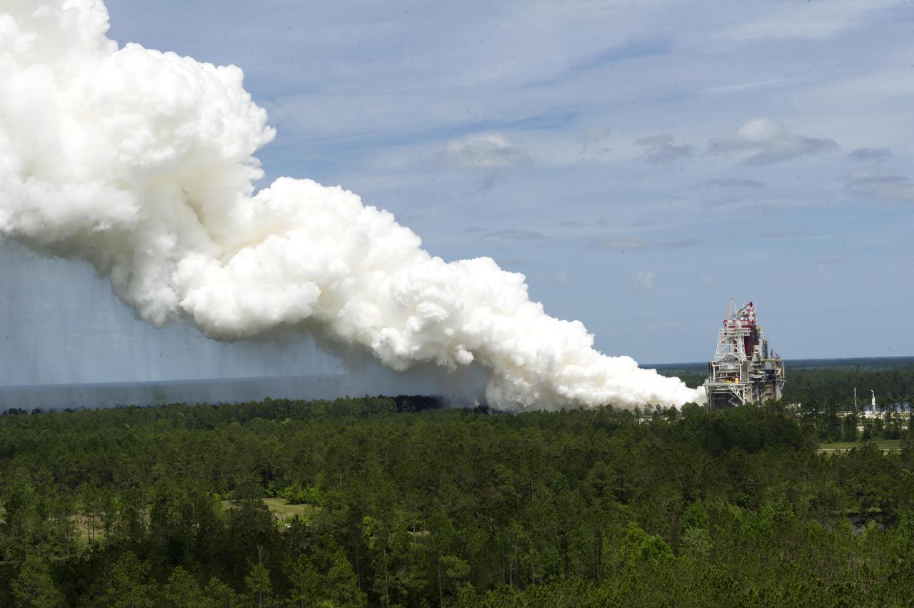
Thousands of people watch the first-ever evening public engine test of a Space Shuttle Main Engine at NASA's John C. Stennis Space Center. The spectacular test marked Stennis Space Center's 20th anniversary celebration of the first Space Shuttle mission.

Approximately 13,000 people fill the grounds at NASA's John C. Stennis Space Center for the first-ever evening public engine test of a Space Shuttle Main Engine. The test marked Stennis Space Center's 20th anniversary celebration of the first Space Shuttle mission.
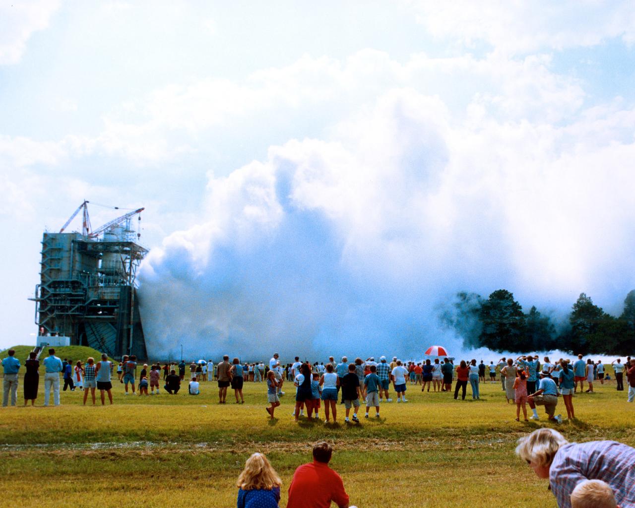
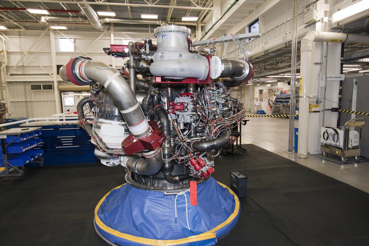
A new NASA Space Shuttle Main Engine (SSME) roars to the approval of more than 2,000 people who came to John C. Stennis Space Center in Hancock County, Miss., on July 25 for a flight-certification test of the SSME Block II configuration. The engine, a new and significantly upgraded shuttle engine, was delivered to NASA's Kennedy Space Center in Florida for use on future shuttle missions. Spectators were able to experience the 'shake, rattle and roar' of the engine, which ran for 520 seconds - the length of time it takes a shuttle to reach orbit.
Over the past year, more than 20,000 people came to Stennis Space Center to witness the 'shake, rattle and roar' of one of the world's most sophisticated engines. Stennis Space Center in south Mississippi is NASA's lead center for rocket propulsion testing. StenniSphere, the visitor center for Stennis Space Center, hosted more than 250,000 visitors in its first year of operation. Of those visitors, 26.4 percent were from Louisiana.
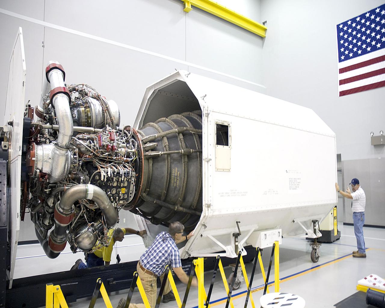
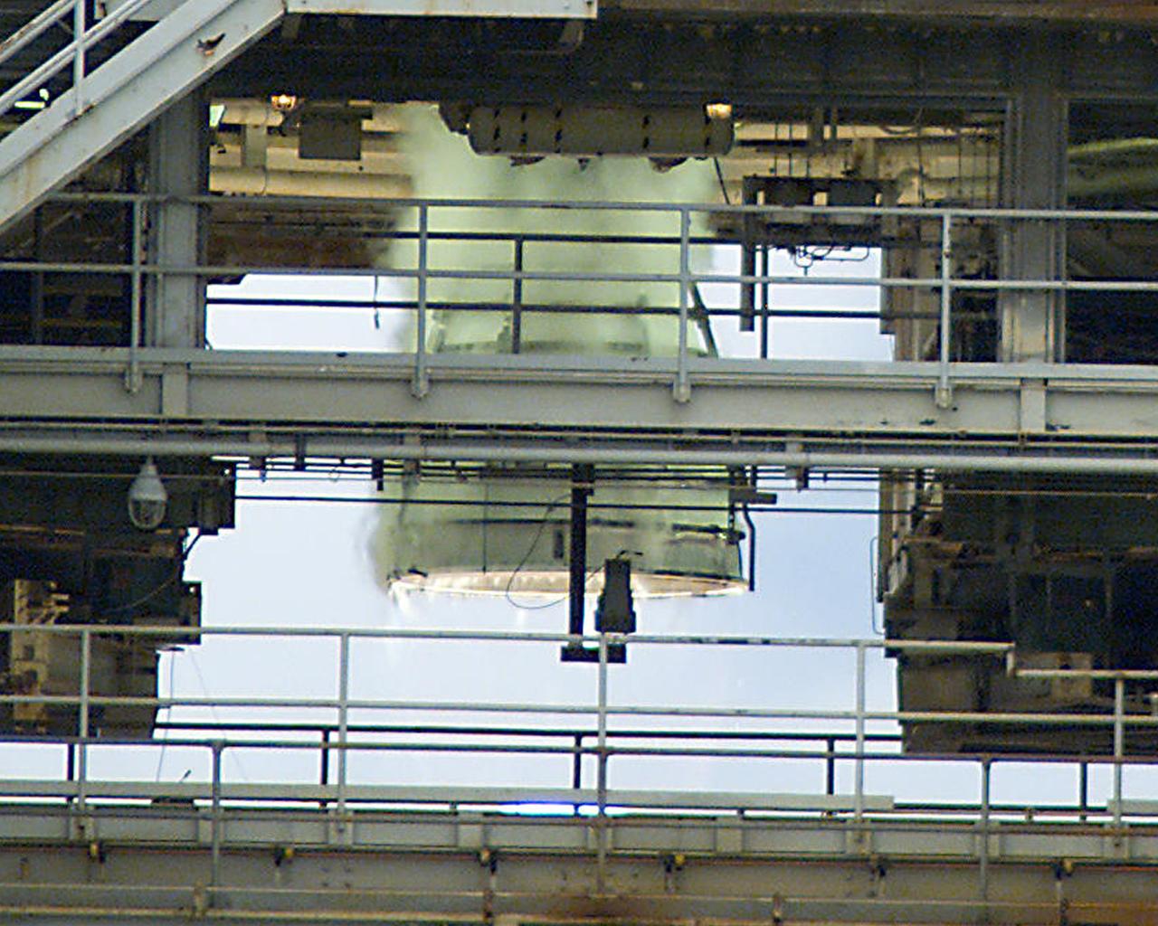
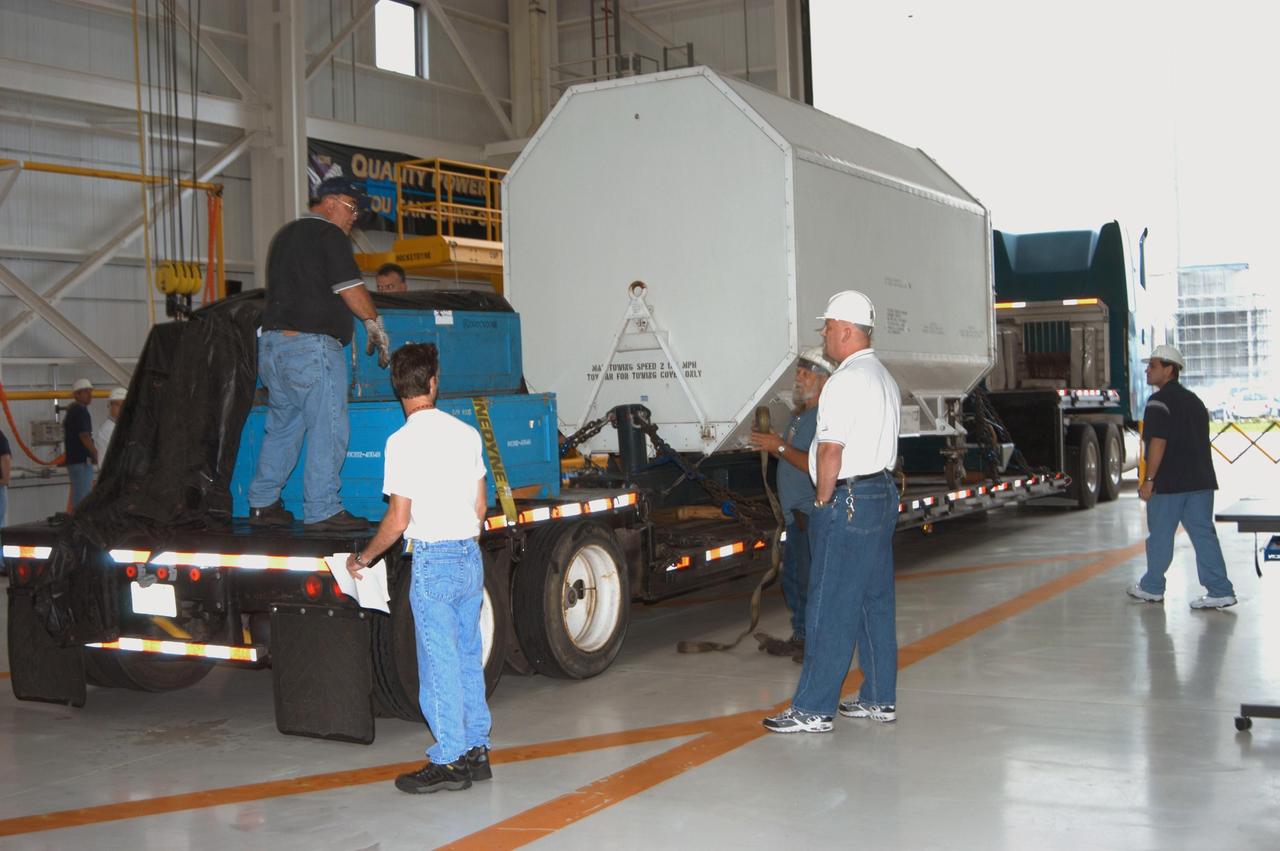
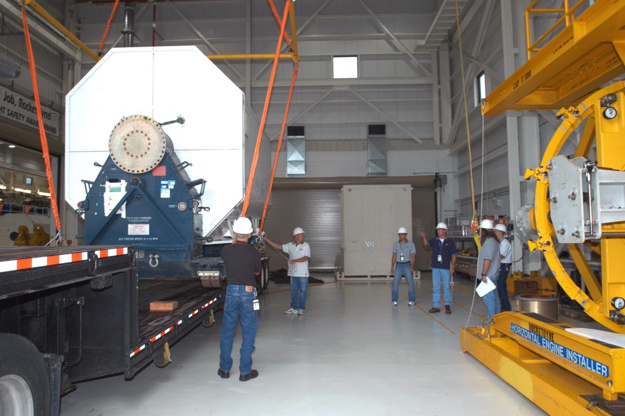
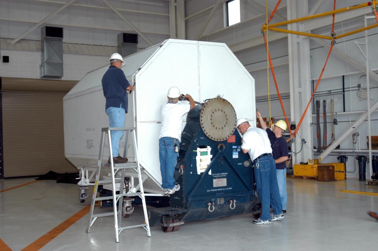
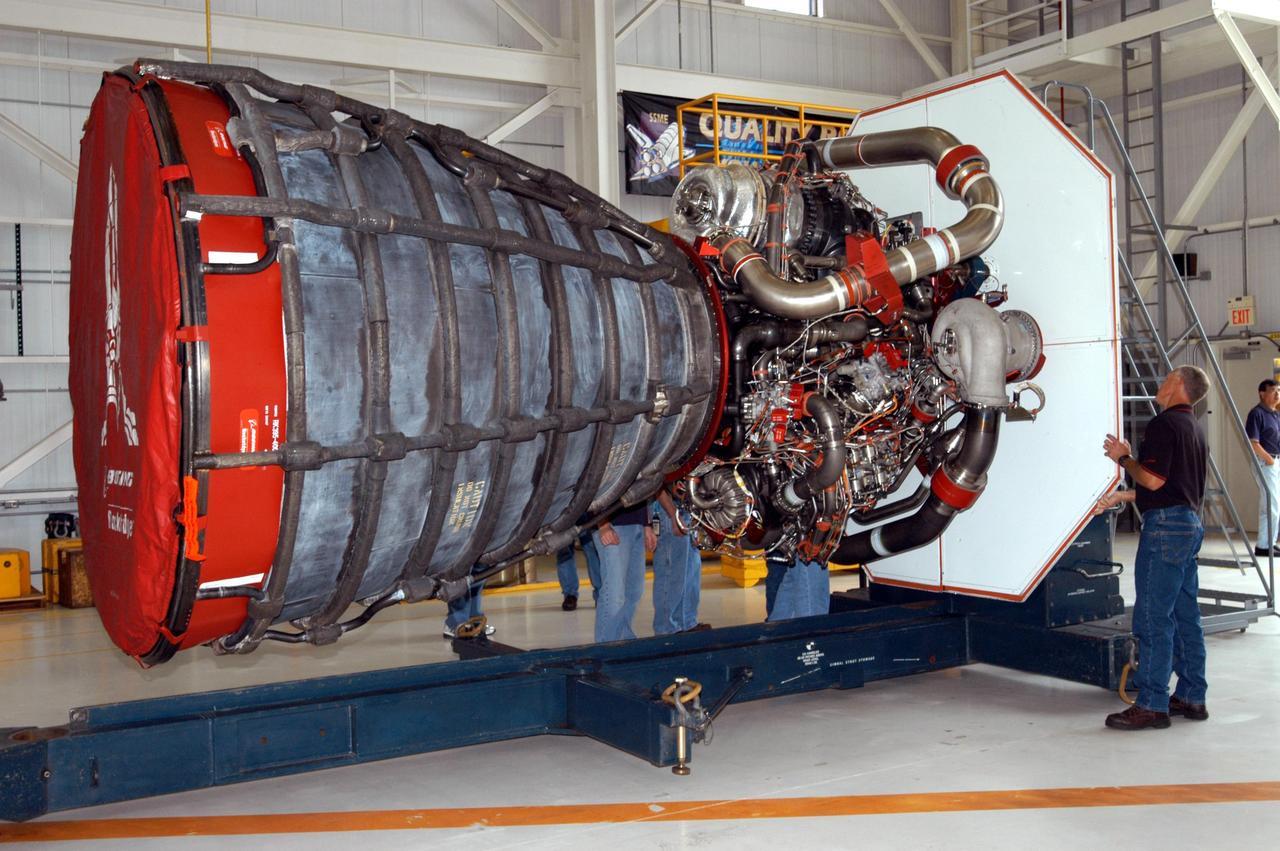
Workers at Stennis Space Center examine space shuttle main engine 2061 upon its arrival Oct. 1. The engine was to be the last shuttle flight engine to be scheduled for testing at Stennis.

Workers at Stennis Space Center examine space shuttle main engine 2061 upon its arrival Oct. 1. The engine was to be the last shuttle flight engine to be scheduled for testing at Stennis.

Employees watch the last planned space shuttle main engine test firing.
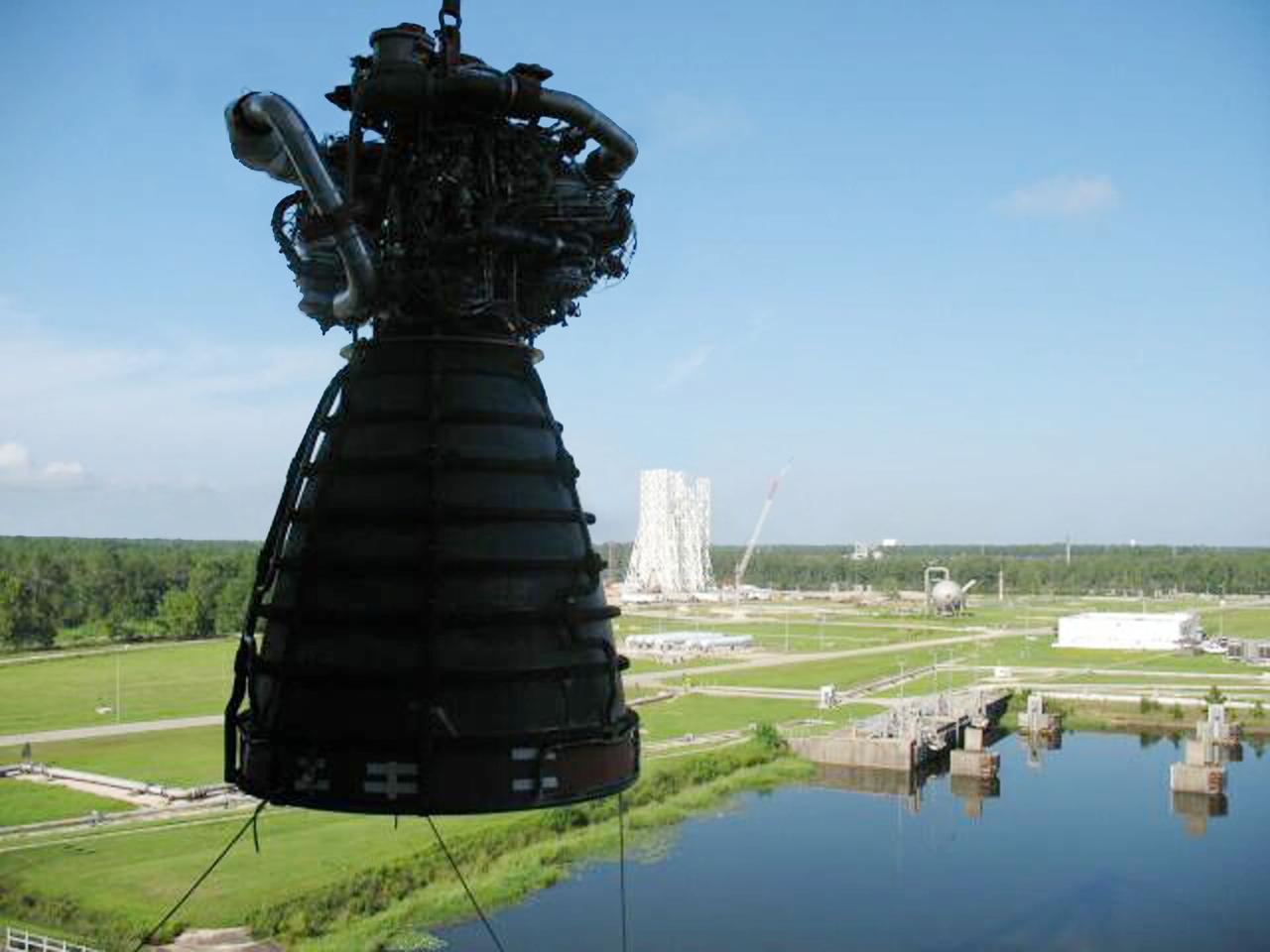
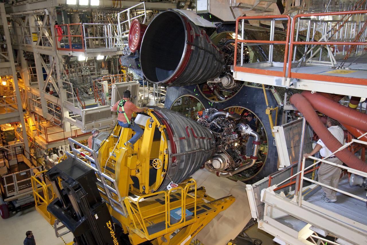
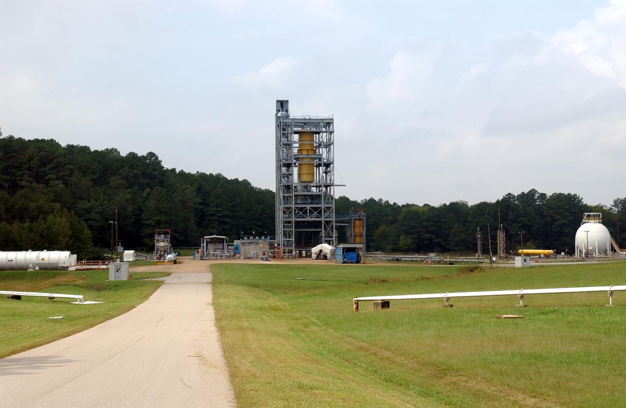
Space shuttle main engine No. 0525 is lifted from the A-2 Test Stand at Stennis Space Center against the backdrop of the new A-3 Test Stand under construction, offering a glimpse of the past and future in the nation's space exploration program. With the shuttle program set to end in 2010, Stennis conducted the last planned space shuttle main engine test on July 29 and now is deactivating the A-2 Test Stand to a safe 'standby' status.
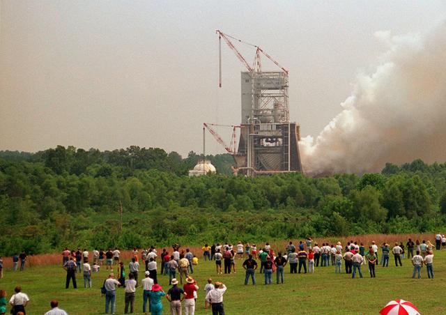
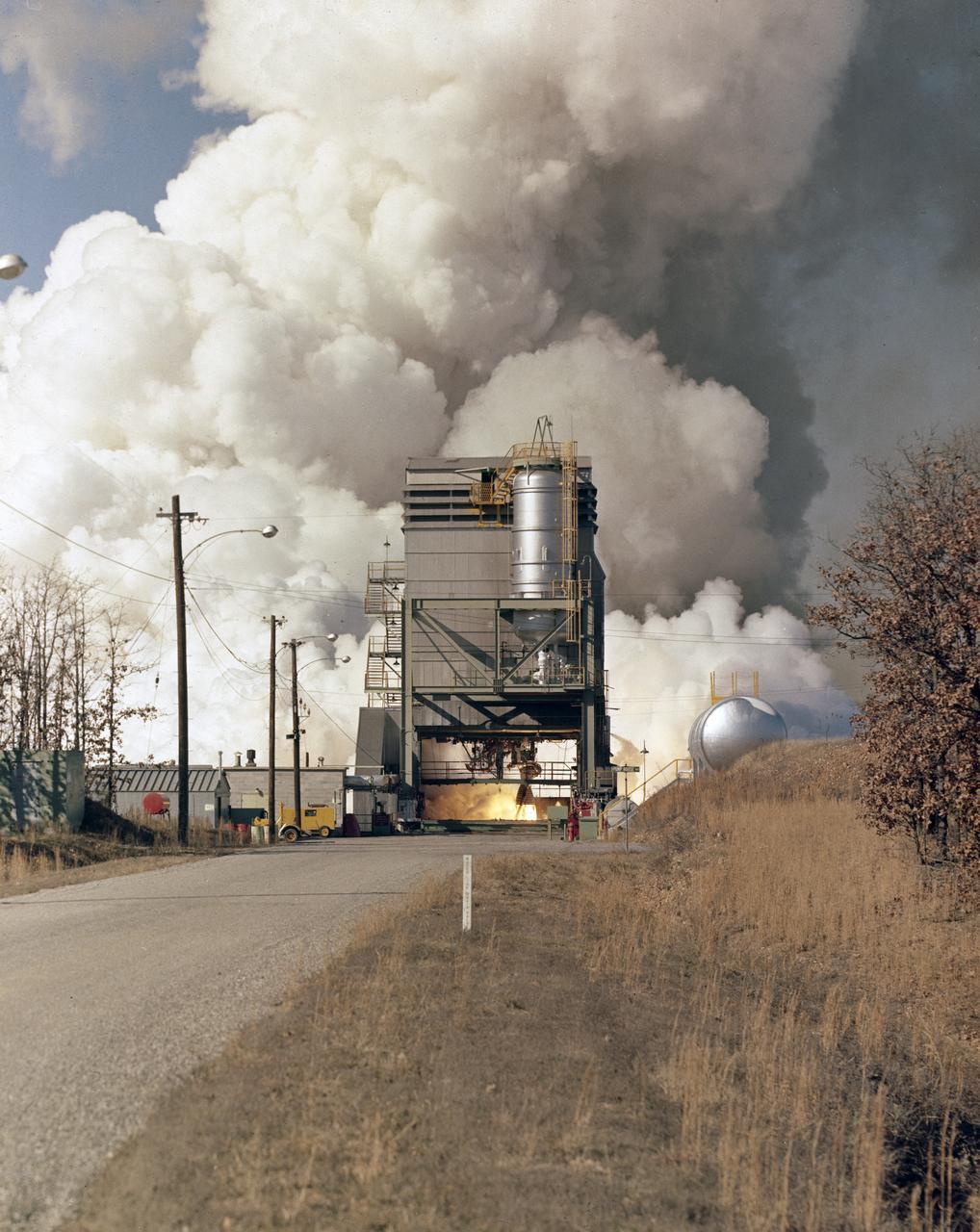
On the 25th Anniversary of the Apollo-11 space launch, Marshall celebrated with a test firing of the Space Shuttle Main Engine at the Technology Test Bed (SSME-TTB). This drew a large crowd who stood in the fields around the test site and watched as plumes of white smoke verified ignition.

The last planned space shuttle main engine test firing takes place on July 29, 2009.

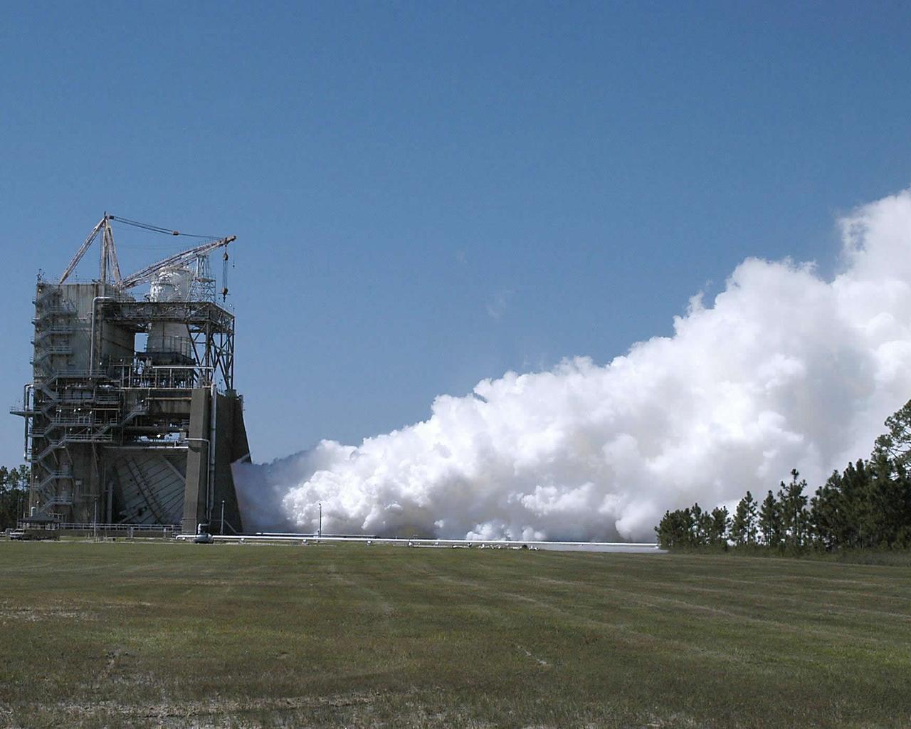
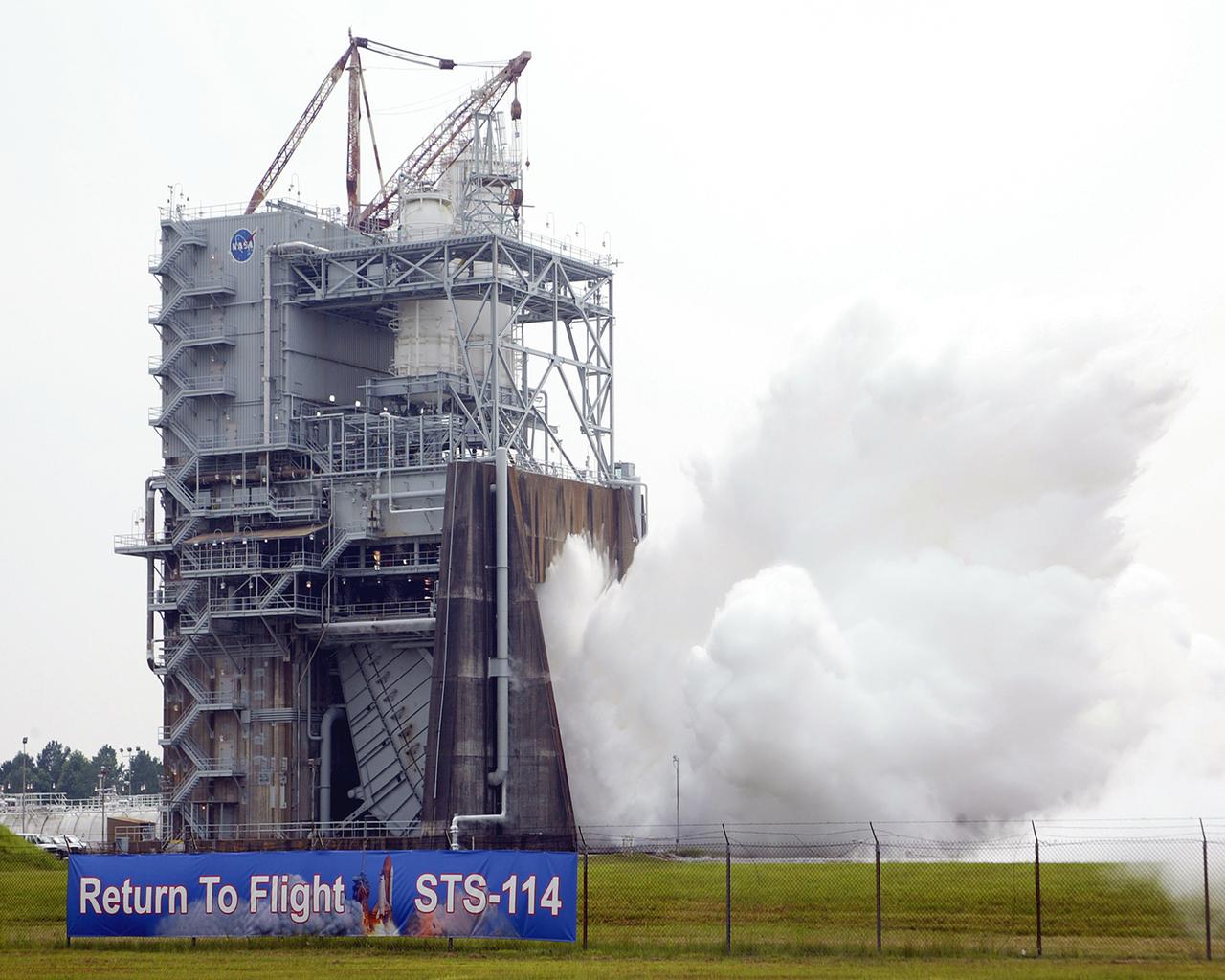
Steam blasts out of the A-2 Test Stand at Stennis Space Center on Oct. 22 as engineers begin a certification test on engine 2061, the last space shuttle main flight engine scheduled to be built. Since 1975, Stennis has tested every space shuttle main engine used in the program - about 50 engines in all. Those engines have powered more than 120 shuttle missions - and no mission has failed as a result of engine malfunction. For the remainder of 2008 and throughout 2009, Stennis will continue testing of various space shuttle main engine components.
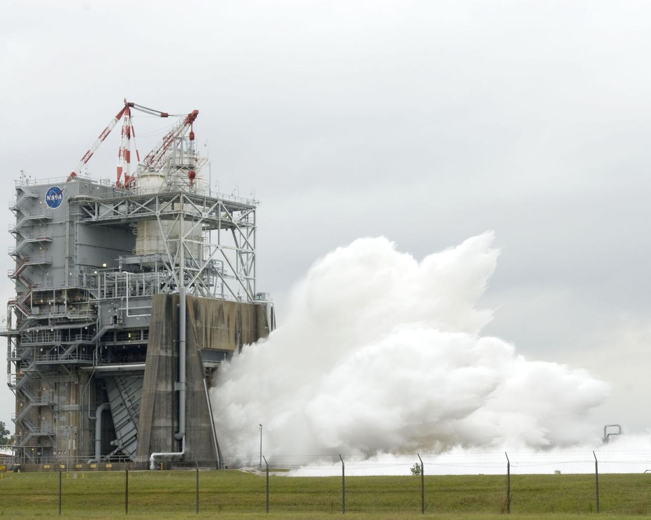
Steam blasts out of the A-2 Test Stand at Stennis Space Center on Oct. 22 as engineers begin a certification test on engine 2061, the last space shuttle main flight engine scheduled to be built. Since 1975, Stennis has tested every space shuttle main engine used in the program - about 50 engines in all. Those engines have powered more than 120 shuttle missions - and no mission has failed as a result of engine malfunction. For the remainder of 2008 and throughout 2009, Stennis will continue testing of various space shuttle main engine components.
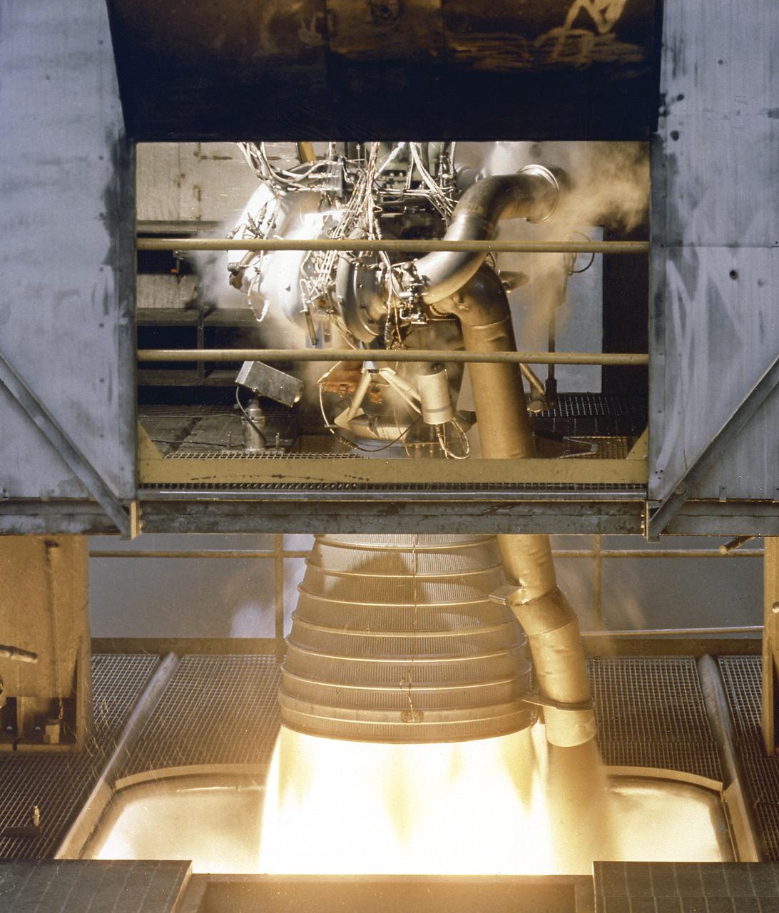
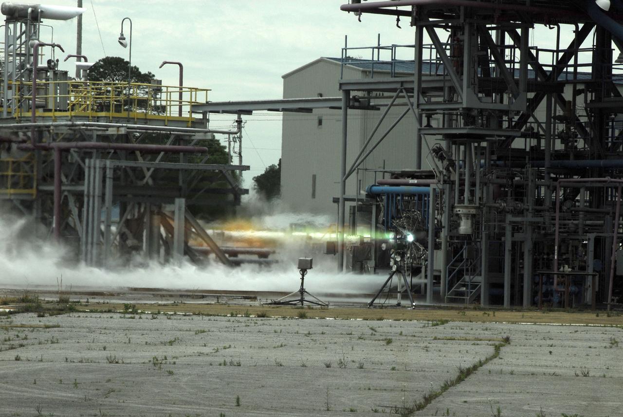
This close-up photo was taken during testing of a Space Shuttle Main Engine on the A-1 Test Stand at Stennis Space Center near Bay St. Louis, Miss. The test was conducted June 19, 2003.
Water vapor surges from the flame deflector of the A-2 Test Stand at NASA's Stennis Space Center on Jan. 9 during the first space shuttle main engine test of the year. The test was an engine acceptance test of flight engine 2058. It's the first space shuttle main engine to be completely assembled at Kennedy Space Center. Objectives also included first-time (green run) tests of a high-pressure oxidizer turbo pump and an Advanced Health System Monitor engine controller. The test ran for the planned duration of 520 seconds.
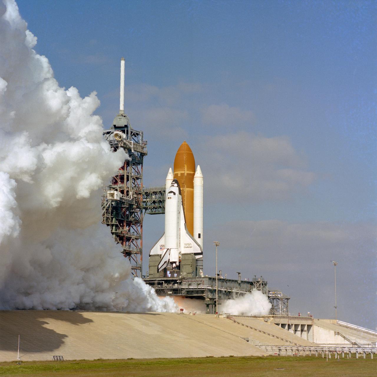
The Space shuttle orbiter Challenger is given a 20-second test firing of its new main engines on December 18, 1982 on pad 39A at the Kennedy Space Center. This test was the first time these engines ahd been tested in the clustered flight configuration.

A space shuttle main engine test April 21, 2006, at NASA Stennis Space Center marked the 40th anniversary of the first rocket engine test at the site. The firing also marked the 25th anniversary of NASA's STS-1, the first space shuttle mission. Then called the Mississippi Test Facility, the center conducted its first test on April 23, 1966. That historic test was on an S-II (second) stage, a cluster of five J-2 engines that powered the Saturn V rockets that took America's Apollo missions to the moon.
The Stennis Space Center conducted the final space shuttle main engine test on its A-1 Test Stand Friday. The A-1 Test Stand was the site of the first test on a shuttle main engine in 1975. Stennis will continue testing shuttle main engines on its A-2 Test Stand through the end of the Space Shuttle Program in 2010. The A-1 stand begins a new chapter in its operational history in October. It will be temporarily decommissioned to convert it for testing the J-2X engine, which will power the upper stage of NASA's new crew launch vehicle, the Ares I. Although this ends the stand's work on the Space Shuttle Program, it will soon be used for the rocket that will carry America's next generation human spacecraft, Orion.
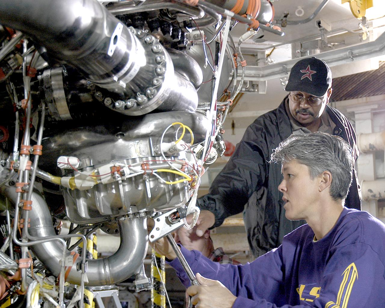
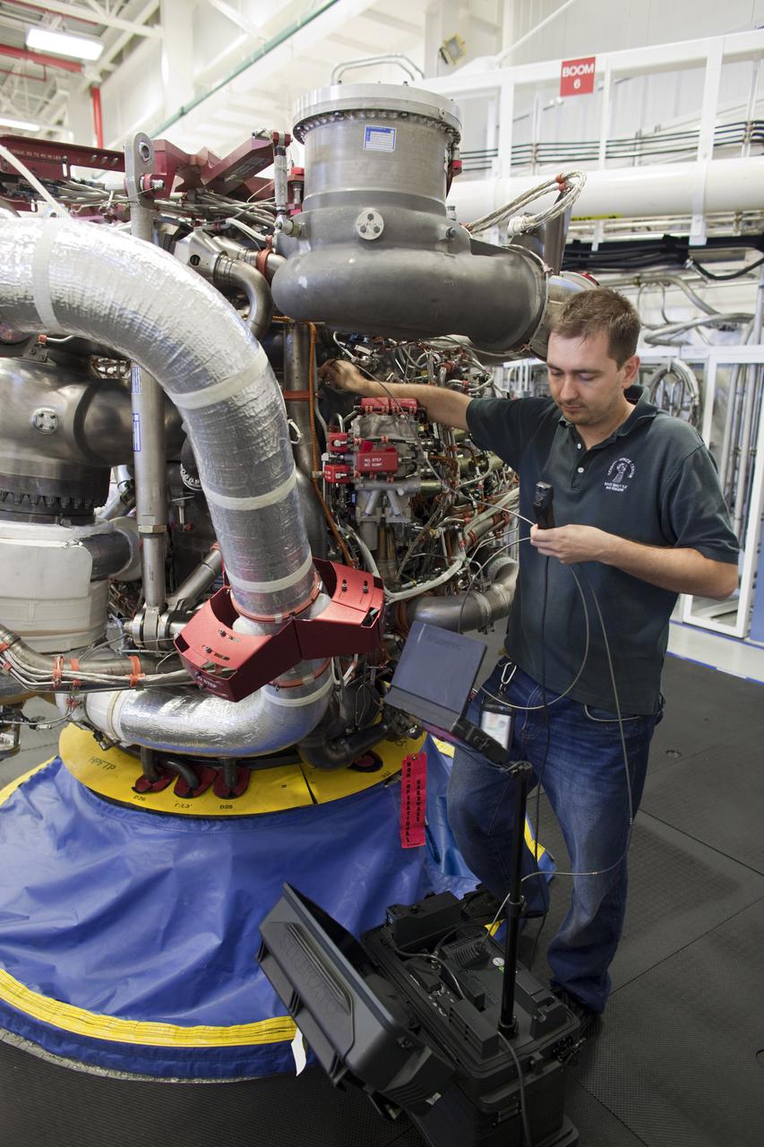
Alvin Pittman Sr., lead electronics technician with Pratt & Whitney Rocketdyne, and Janine Cuevas, a mechanical technician with PWR, perform final preparations on the space shuttle main engine tested Oct. 25, 2005, at NASA's Stennis Space Center. It was the first main engine test since Hurricane Katrina hit the Gulf Coast on Aug. 29.
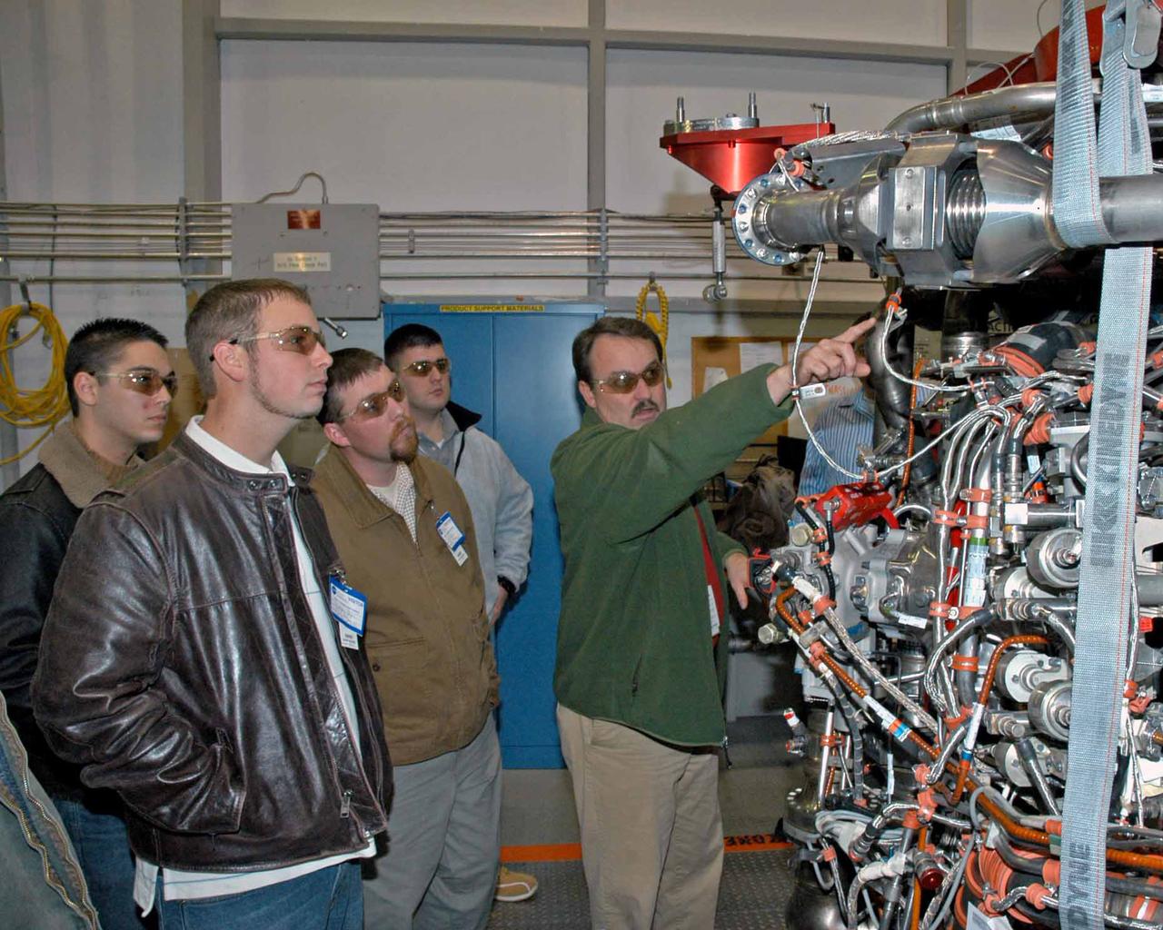
Pratt & Whitney Rocketdyne's Jeff Hansell, right, explains functions of a space shuttle main engine to Pearl River Community College Aviation Maintenance Technology Program students. Christopher Bryon, left, of Bay St. Louis, Ret Tolar of Kiln, Dan Holston of Baxterville and Billy Zugg of Long Beach took a recent tour of the SSME Processing Facility and the E-1 Test Complex at Stennis Space Center in South Mississippi. The students attend class adjacent to the Stennis International Airport tarmac in Kiln, where they get hands-on experience. PRCC's program prepares students to be responsible for the inspection, repair and maintenance of technologically advanced aircraft. A contractor to NASA, Pratt & Whitney Rocketdyne in Canoga Park, Calif., manufactures the space shuttle main engine and its high-pressure turbo pumps. SSC was established in the 1960s to test the huge engines for the Saturn V moon rockets. Now 40 years later, the center tests every main engine for the space shuttle, and is America's largest rocket engine test complex. SSC will soon begin testing the rocket engines that will power spacecraft carrying Americans back to the moon and on to Mars.
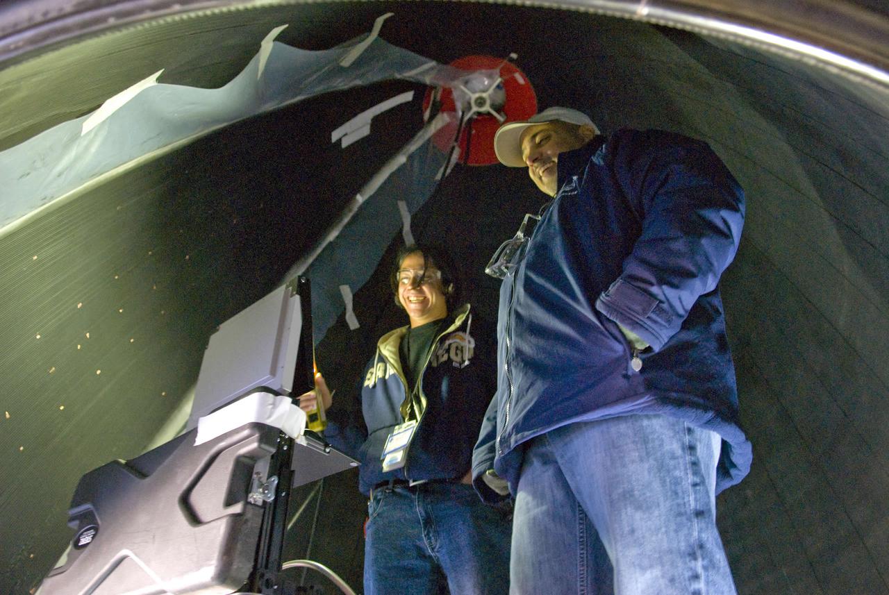
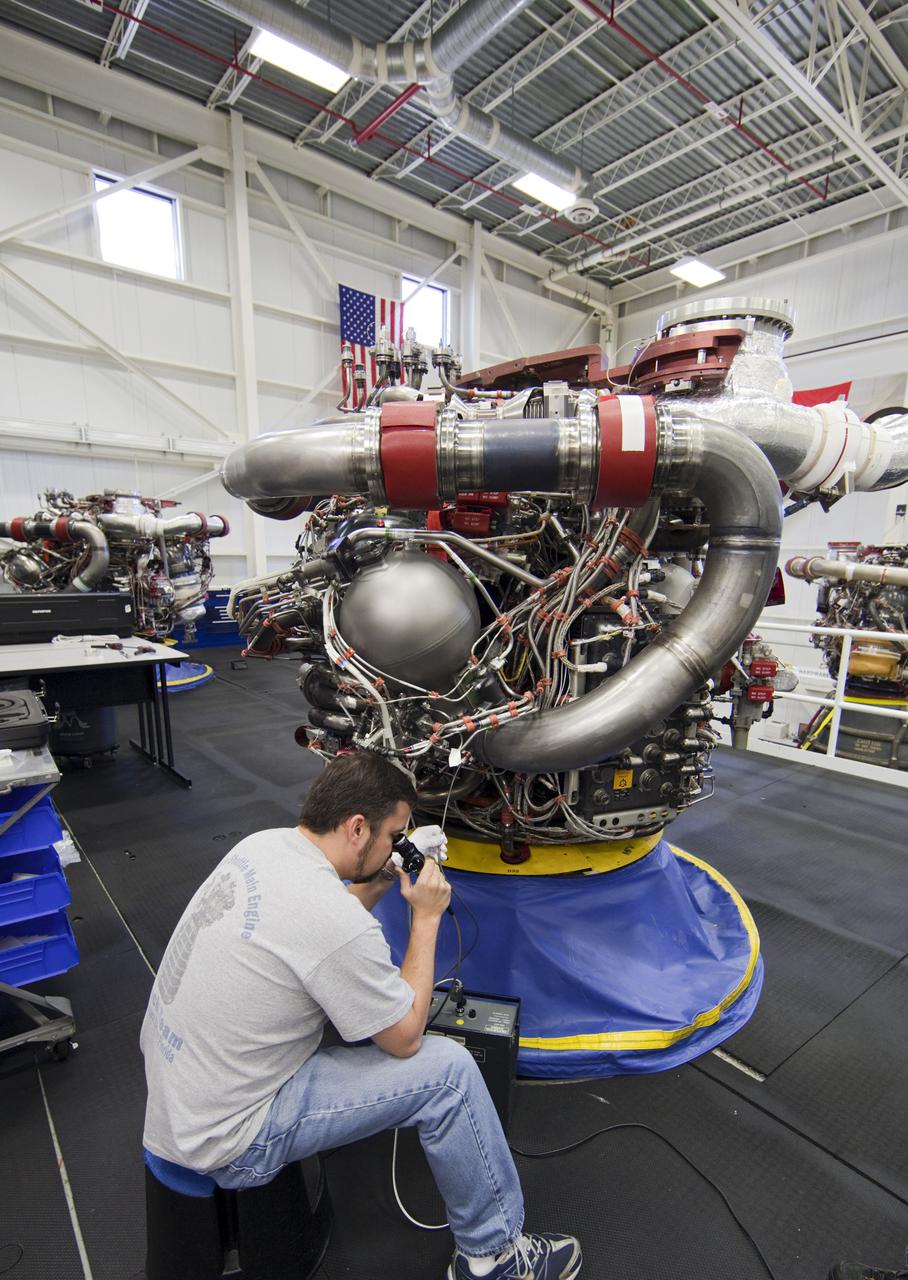
Joel Perez (left) and Jay Labat, both of Pratt & Whitney Rocketdyne, are in close quarters as they check for leaks inside the nozzle of a space shuttle main engine mounted on the A-2 Test Stand.
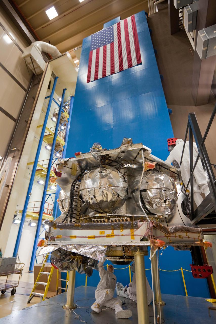
Technicians prepare NASA Juno spacecraft for a functional test of its main engine cover.
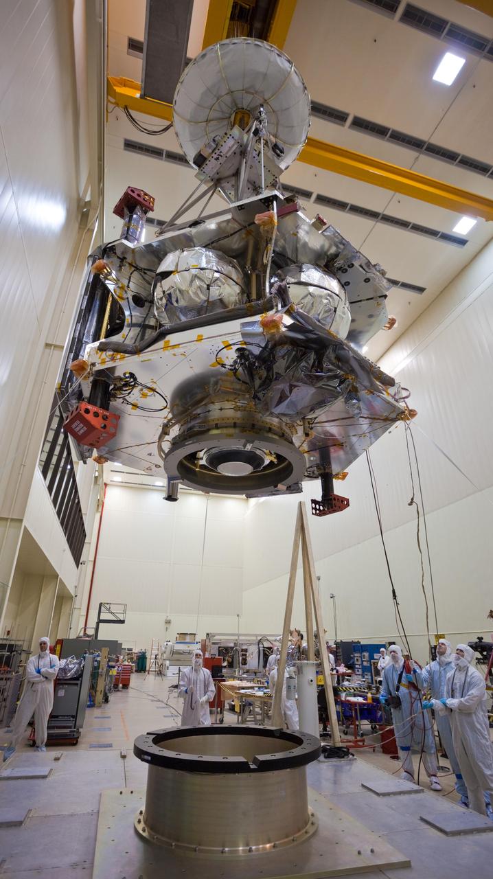
Technicians transfer NASA Juno spacecraft from its rotation fixture to the base of its shipping container in preparation for a move to environmental testing facilities. Juno’s main engine, its cover closed, is visible on the spacecraft’s underside.
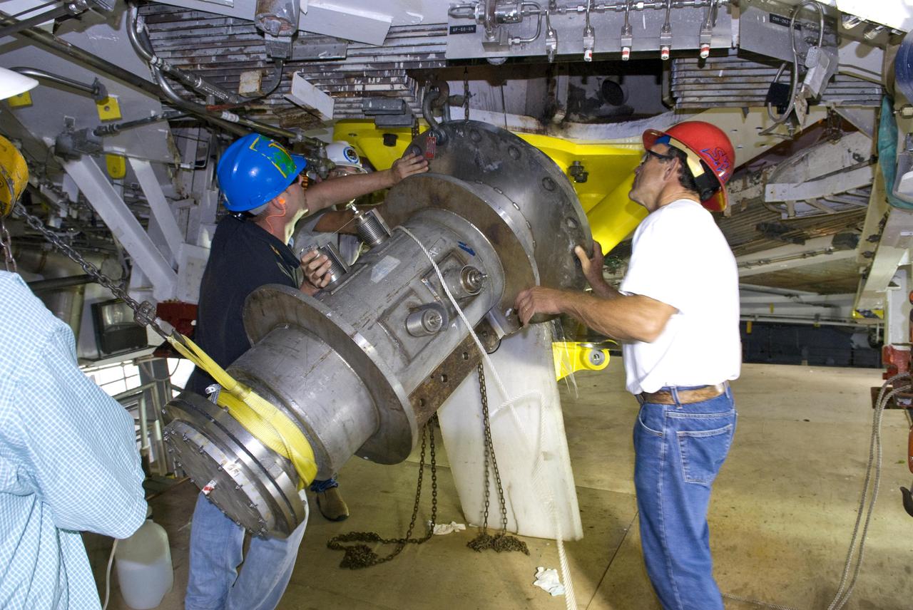
John C. Stennis Space Center employees remove space shuttle main engine run ducts from the A-2 Test Stand engine deck Oct. 25, 2010. Testing of space shuttle main engines concluded in July 2009. Stennis is preparing the A-2 Test Stand for testing the next-generation J-2X rocket engine being developed. Testing of the new engine is scheduled to begin in 2011.
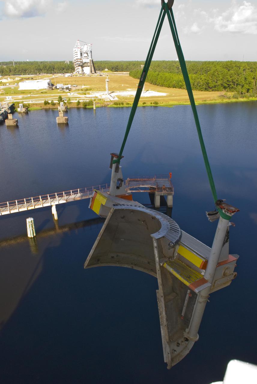
John C. Stennis Space Center employees remove one-half of the A-2 Test Stand clamshell used for testing space shuttle main engines. Space shuttle main engine testing concluded July 2009; the A-2 stand now is being prepared for testing the next-generation J-2X rocket engine in development. Testing of the J-2X engine is scheduled to begin in 2011.

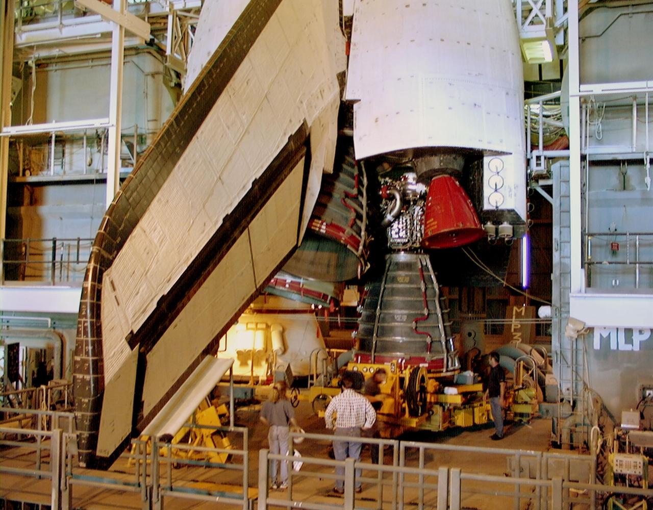
KENNEDY SPACE CENTER, FLA. -- This close-up of Space Shuttle Endeavour's main engines shows the replacement for main engine No. 3 (lower right) ready to be installed. Following routine testing procedures on a separate test engine, analysis revealed delamination on the wall of the engine's main combustion chamber. When data revealed that one of Endeavour's engines had undergone similar testing procedures, managers opted to replace the suspect engine as a precaution. Space Shuttle Endeavour is targeted for launch at 1:11 p.m. EST Jan. 13, 2000, on mission STS-99. It will be Endeavour's 14th flight. STS-99 is the Shuttle Radar Topography Mission
A close-up image of the single H-1 engine was test-fired at Canoga Park, California. Initial development of testing for the H-1 engine took place in the engineering facilities at Rocketdyne's main plant in Canoga Park, California.
In this photograph, the single H-1 engine was test-fired at Canoga Park, California. Initial development of testing for the H-1 engine took place in the engineering facilities at Rocketdyne's main plant in Canoga Park, California.
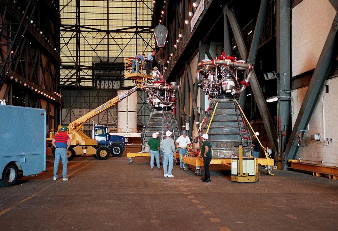
KENNEDY SPACE CENTER, FLA. -- Workers in the Vehicle Assembly Building move orbiter Endeavour's main engine No. 3 (in front) out of the way before moving the replacement engine into place. Following routine testing procedures on a separate test engine, analysis revealed delamination on the wall of the engine's main combustion chamber. When data revealed that one of Endeavour's engines had undergone similar testing procedures, managers opted to replace the suspect engine as a precaution. Space Shuttle Endeavour is targeted for launch on mission STS-99 on Jan. 13, 2000, at 1:11 p.m. EST. STS-99 is the Shuttle Radar Topography Mission

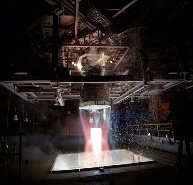
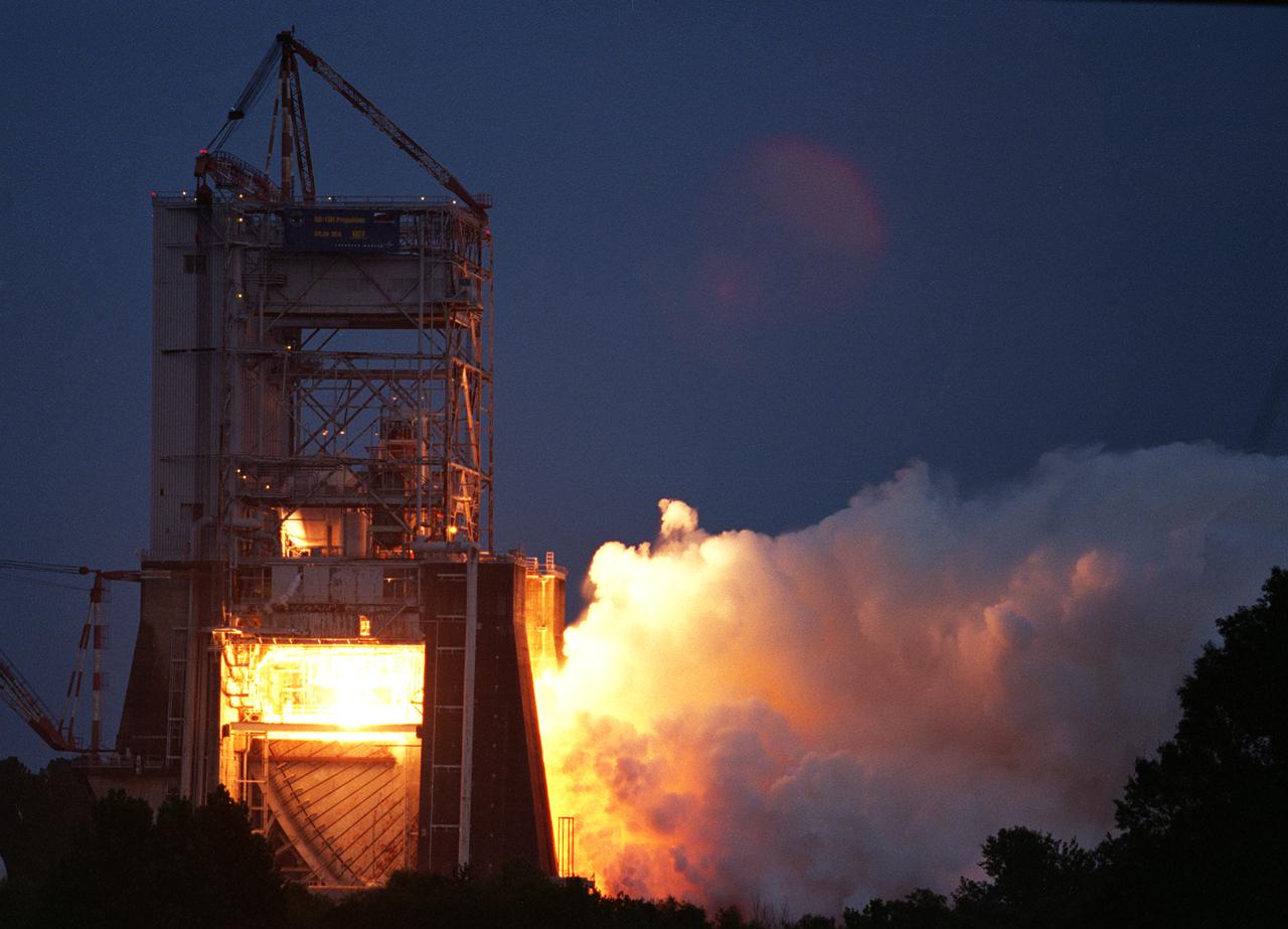
A Space Shuttle Main Engine undergoes test-firing at the National Space Technology Laboratories (now the Sternis Space Center) in Mississippi. The Marshall Space Flight Center had management responsibility of Space Shuttle propulsion elements, including the Main Engines.

NASA's Pegasus barge arrived at Stennis Space Center on Nov. 16, delivering space shuttle main engine ground support equipment to the south Mississippi facility. Stennis tested every main engine used on all 135 space shuttle flights.

A Space Shuttle Main Engine (SSME) - hot and cold cycles turbine blade test firing.

A modified Space Shuttle Main Engine is static fired at Marshall's Technology Test Bed.
A modified Space Shuttle Main Engine is static fired at Marshall's Technology Test Bed.

A modified Space Shuttle Main Engine is static fired at Marshall's Technology Test Bed.
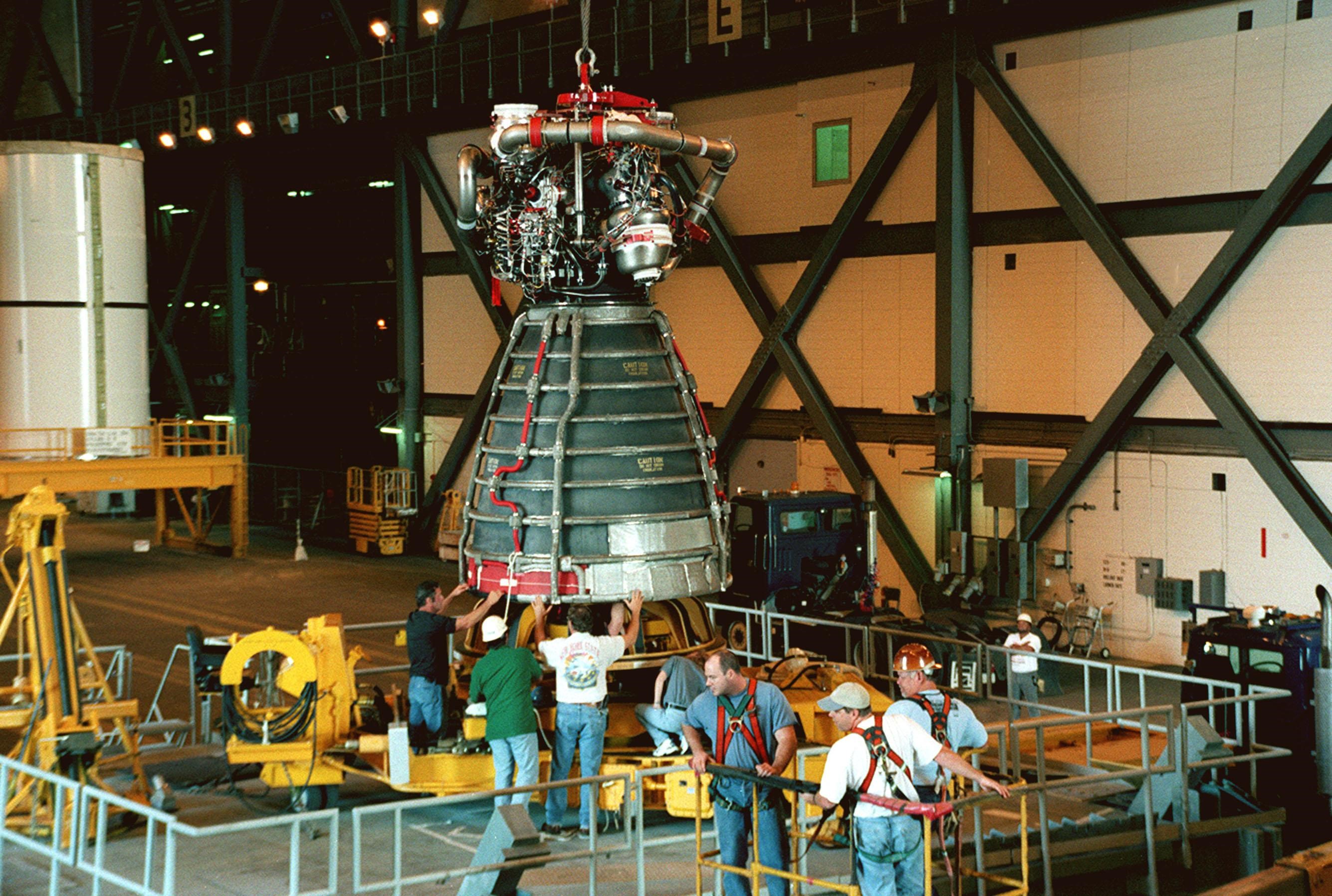
KENNEDY SPACE CENTER, FLA. -- Workers in the Vehicle Assembly Building move orbiter Endeavour's replacement main engine No. 3 onto a work stand to prepare it for installation in the orbiter. Following routine testing procedures on a separate test engine, analysis revealed delamination on the wall of the engine's main combustion chamber. When data revealed that one of Endeavour's engines had undergone similar testing procedures, managers opted to replace the suspect engine as a precaution. Space Shuttle Endeavour is targeted for launch on mission STS-99 on Jan. 13, 2000, at 1:11 p.m. EST. STS-99 is the Shuttle Radar Topography Mission
KENNEDY SPACE CENTER, FLA. -- Endeavour's replacement main engine No. 3 is moved underneath the orbiter for installation. Following routine testing procedures on a separate test engine, analysis revealed delamination on the wall of the engine's main combustion chamber. When data revealed that one of Endeavour's engines had undergone similar testing procedures, managers opted to replace the suspect engine as a precaution. Space Shuttle Endeavour is targeted for launch at 1:11 p.m. EST Jan. 13, 2000, on mission STS-99. It will be Endeavour's 14th flight. STS-99 is the Shuttle Radar Topography Mission
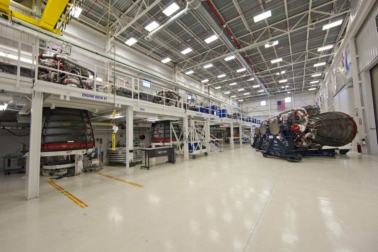
CAPE CANAVERAL, Fla. – At NASA’s Kennedy Space Center in Florida, all six Pratt Whitney Rocketdyne space shuttle main engines (SSMEs) from space shuttle Endeavour's STS-134 and space shuttle Atlantis' STS-135 missions sit in test cells inside the Engine Shop. To the right are three more main engines on platforms. For the first time, all 15 main engines are in the Engine Shop at the same time. They are being prepared for shipment to NASA's Stennis Space Center in Mississippi for storage following the completion of the Space Shuttle Program. The engines are being repurposed for use on NASA’s Space Launch System heavy lift rocket. Photo credit: NASA_Dimitri Gerondidakis
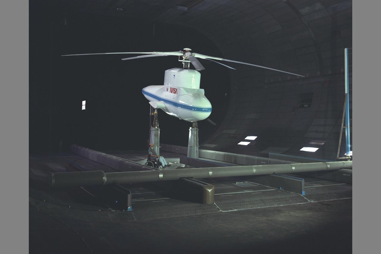
Sikorsky Bearingless Main rotor (SBMR) mounted on the Ames Rotor Test Apparatus (RTA) for testing in the NASA Ames 40x80ft Subsonic Wind Tunnel, test-584. Shown with NASA engineer Bob McMahon
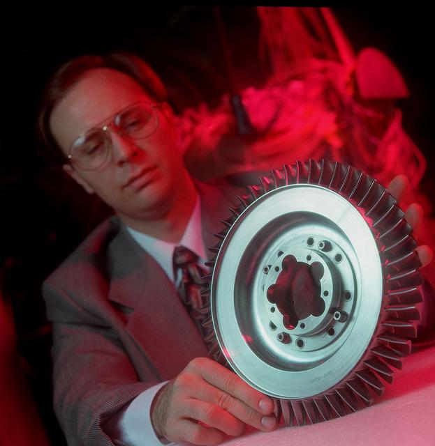
A NASA scientist displays Space Shuttle Main Engine (SSME) turbine component which underwent air flow tests at Marshall's Structures and Dynamics Lab. Such studies could improve efficiency of aircraft engines, and lower operational costs.
CAPE CANAVERAL, Fla. – Inside the Engine Shop at NASA’s Kennedy Space Center in Florida, a technician performs a boroscope test on a high pressure oxidizer pump on one of the Pratt Whitney Rocketdyne space shuttle main engines (SSMEs) positioned in a test cell. For the first time, all 15 main engines are in the Engine Shop at the same time. They are being prepared for shipment to NASA's Stennis Space Center in Mississippi for storage following the completion of the Space Shuttle Program. The engines are being repurposed for use on NASA’s Space Launch System heavy lift rocket. Photo credit: NASA_Dimitri Gerondidakis
CAPE CANAVERAL, Fla. – Inside the Engine Shop at NASA’s Kennedy Space Center in Florida, a technician performs a boroscope test on a high pressure oxidizer pump on one of the Pratt Whitney Rocketdyne space shuttle main engines (SSMEs) positioned in a test cell. For the first time, all 15 main engines are in the Engine Shop at the same time. They are being prepared for shipment to NASA's Stennis Space Center in Mississippi for storage following the completion of the Space Shuttle Program. The engines are being repurposed for use on NASA’s Space Launch System heavy lift rocket. Photo credit: NASA_Dimitri Gerondidakis
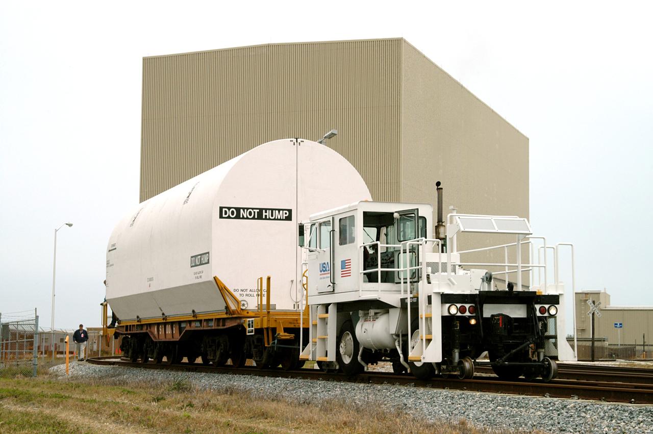
KENNEDY SPACE CENTER, FLA. - An engine pulls the container enclosing a segment of a solid rocket booster from the Rotation Processing and Surge Facility. The container will join others on the main track for a trip to Utah where the segments will undergo firing. The segments were part of the STS-114 stack. It is the first time actual flight segments that had been stacked for flight in the VAB are being returned for testing. They will undergo firing, which will enable inspectors to check the viability of the solid and verify the life expectancy for stacked segments.

This test conducted in May 1988 shows what happens during launch if a space shuttle main engine fails. The test was conducted in the 10X10 supersonic wind tunnel at the John H. Glenn Research Center.
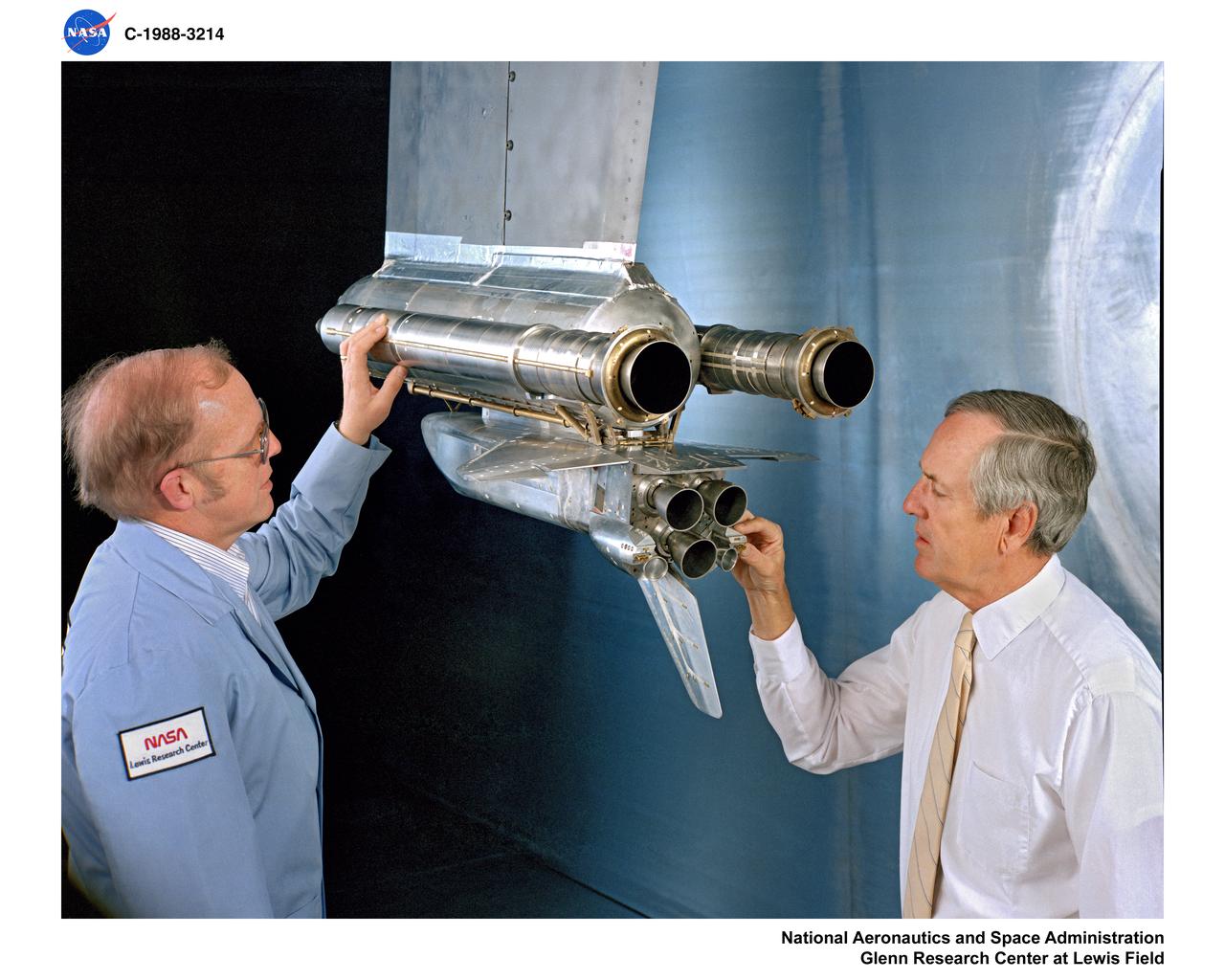
This test conducted in May 1988 shows what happens during launch if a space shuttle main engine fails. The test was conducted in the 10X10 supersonic wind tunnel at the John H. Glenn Research Center.

This test conducted in May 1988 shows what happens during launch if a space shuttle main engine fails. The test was conducted in the 10X10 supersonic wind tunnel at the John H. Glenn Research Center.
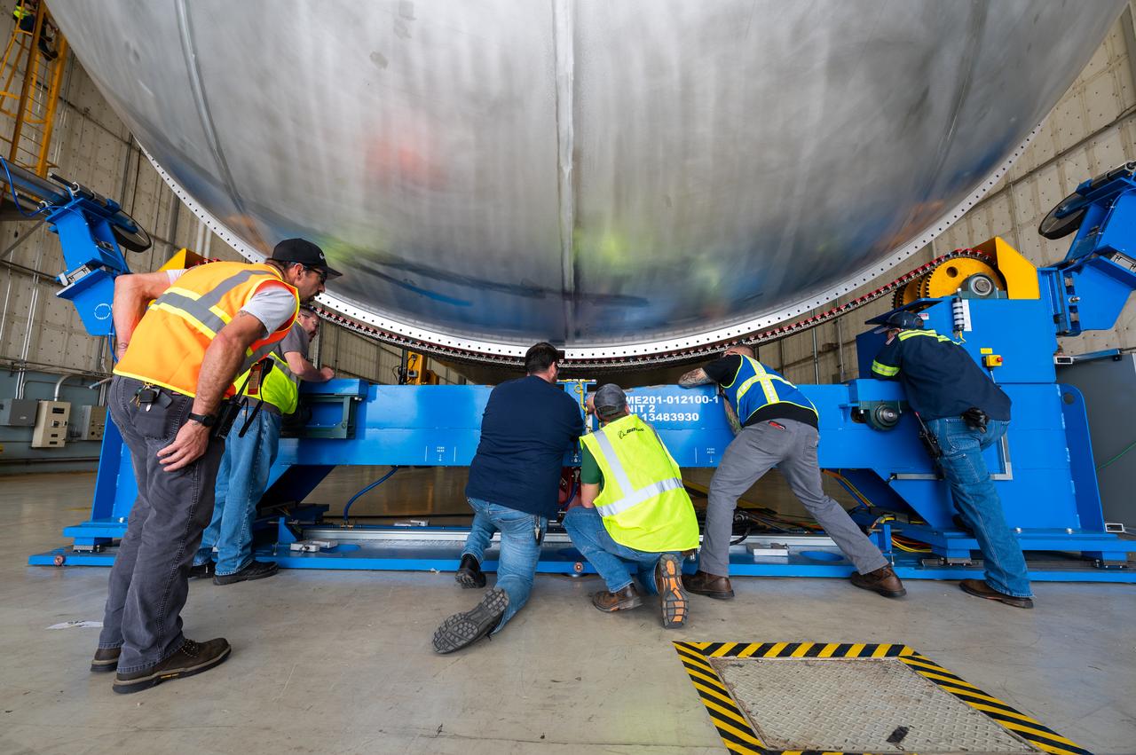
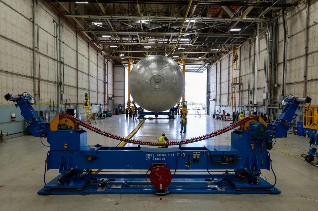
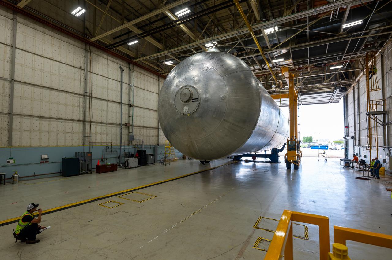
The core stage liquid hydrogen tank for the Artemis III mission completed proof testing, and technicians returned it to the main factory building at NASA’s Michoud Assembly Facility in New Orleans where it will undergo more outfitting. As part of proof testing, technicians apply a simple soap solution and check for leaks by observing any bubble formation on the welds. The technician removed the bubble solution with distilled water and then dried the area of application to prevent corrosion. To build the Space Launch System (SLS) rocket’s 130-foot core stage liquid hydrogen tank, engineers use robotic tools to weld five-barrel segments. This process results in a tank with around 1,900 feet, or more than six football fields, of welds that must be tested by hand. After the leak tests, the core stage lead, Boeing, pressurized the SLS tank to further ensure there were no leaks. After it passed proof testing, technicians moved the Artemis III liquid hydrogen tank to Michoud’s main factory. Soon, the technicians will prime and apply a foam-based thermal protection system that protects the tank during launch. Later, the tank will be joined with other parts of the core stage to form the entire 212-foot rocket stage with its four RS-25 engines that produce 2 million pounds of thrust to help launch the rocket. Artemis III will land the first astronauts on the lunar surface.
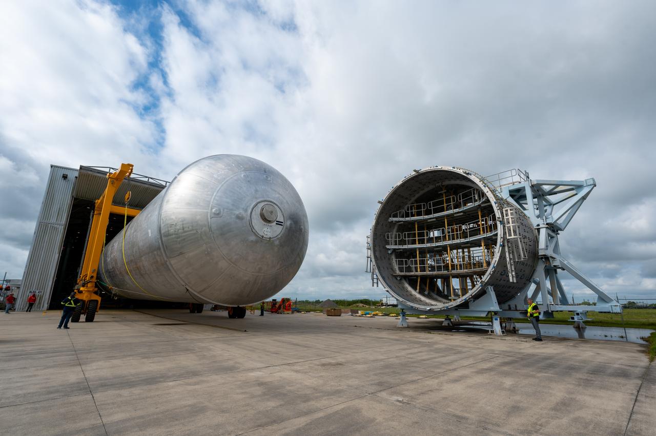
The core stage liquid hydrogen tank for the Artemis III mission completed proof testing, and technicians returned it to the main factory building at NASA’s Michoud Assembly Facility in New Orleans where it will undergo more outfitting. As part of proof testing, technicians apply a simple soap solution and check for leaks by observing any bubble formation on the welds. The technician removed the bubble solution with distilled water and then dried the area of application to prevent corrosion. To build the Space Launch System (SLS) rocket’s 130-foot core stage liquid hydrogen tank, engineers use robotic tools to weld five-barrel segments. This process results in a tank with around 1,900 feet, or more than six football fields, of welds that must be tested by hand. After the leak tests, the core stage lead, Boeing, pressurized the SLS tank to further ensure there were no leaks. After it passed proof testing, technicians moved the Artemis III liquid hydrogen tank to Michoud’s main factory. Soon, the technicians will prime and apply a foam-based thermal protection system that protects the tank during launch. Later, the tank will be joined with other parts of the core stage to form the entire 212-foot rocket stage with its four RS-25 engines that produce 2 million pounds of thrust to help launch the rocket. Artemis III will land the first astronauts on the lunar surface.
The core stage liquid hydrogen tank for the Artemis III mission completed proof testing, and technicians returned it to the main factory building at NASA’s Michoud Assembly Facility in New Orleans where it will undergo more outfitting. As part of proof testing, technicians apply a simple soap solution and check for leaks by observing any bubble formation on the welds. The technician removed the bubble solution with distilled water and then dried the area of application to prevent corrosion. To build the Space Launch System (SLS) rocket’s 130-foot core stage liquid hydrogen tank, engineers use robotic tools to weld five-barrel segments. This process results in a tank with around 1,900 feet, or more than six football fields, of welds that must be tested by hand. After the leak tests, the core stage lead, Boeing, pressurized the SLS tank to further ensure there were no leaks. After it passed proof testing, technicians moved the Artemis III liquid hydrogen tank to Michoud’s main factory. Soon, the technicians will prime and apply a foam-based thermal protection system that protects the tank during launch. Later, the tank will be joined with other parts of the core stage to form the entire 212-foot rocket stage with its four RS-25 engines that produce 2 million pounds of thrust to help launch the rocket. Artemis III will land the first astronauts on the lunar surface.
The core stage liquid hydrogen tank for the Artemis III mission completed proof testing, and technicians returned it to the main factory building at NASA’s Michoud Assembly Facility in New Orleans where it will undergo more outfitting. As part of proof testing, technicians apply a simple soap solution and check for leaks by observing any bubble formation on the welds. The technician removed the bubble solution with distilled water and then dried the area of application to prevent corrosion. To build the Space Launch System (SLS) rocket’s 130-foot core stage liquid hydrogen tank, engineers use robotic tools to weld five-barrel segments. This process results in a tank with around 1,900 feet, or more than six football fields, of welds that must be tested by hand. After the leak tests, the core stage lead, Boeing, pressurized the SLS tank to further ensure there were no leaks. After it passed proof testing, technicians moved the Artemis III liquid hydrogen tank to Michoud’s main factory. Soon, the technicians will prime and apply a foam-based thermal protection system that protects the tank during launch. Later, the tank will be joined with other parts of the core stage to form the entire 212-foot rocket stage with its four RS-25 engines that produce 2 million pounds of thrust to help launch the rocket. Artemis III will land the first astronauts on the lunar surface.
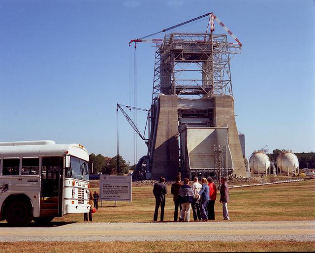
Constructed in 1964, the S-IC Static Test Stand was designed to develop and test the first stage (S-IC) of the Saturn V launch vehicle. In the 1974 the test stand was modified to test the liquid hydrogen tank on the Space Shuttle External Tank. The facility was again modified in 1986 and its name was changed to the Advanced Engine Test Facility. These modifications were made to accommodate the Technology Test Bed engine which is a derivative of the Space Shuttle Main Engine.
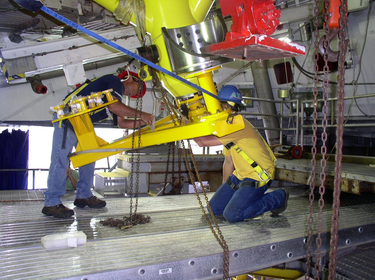
John C. Stennis Space Center employees install a new master interface tool on the A-2 Test Stand on Oct. 27, 2010. Until July 2009, the stand had been used for testing space shuttle main engines. With that test series complete, employees are preparing the stand for testing the next-generation J-2X rocket engine being developed. Testing of the new engine is scheduled to begin in 2011.
CAPE CANAVERAL, Fla. -- In the Space Shuttle Main Engine Processing Facility at NASA's Kennedy Space Center in Florida, space shuttle main engine No. 1 is outfitted with a new turbopump. A suspect turbopump experienced an issue during torque testing and had to be removed and replaced for Discovery's STS-133 mission to the International Space Station. Next, all three main engines will be transported back to Orbiter Processing Facility-3 and reinstalled. The shuttle and its STS-133 crew are targeted to deliver the Express Logistics Carrier-4 filled with external payloads and experiments, as well as critical spare components to the station later this year. Photo credit: NASA_Jack Pfaller
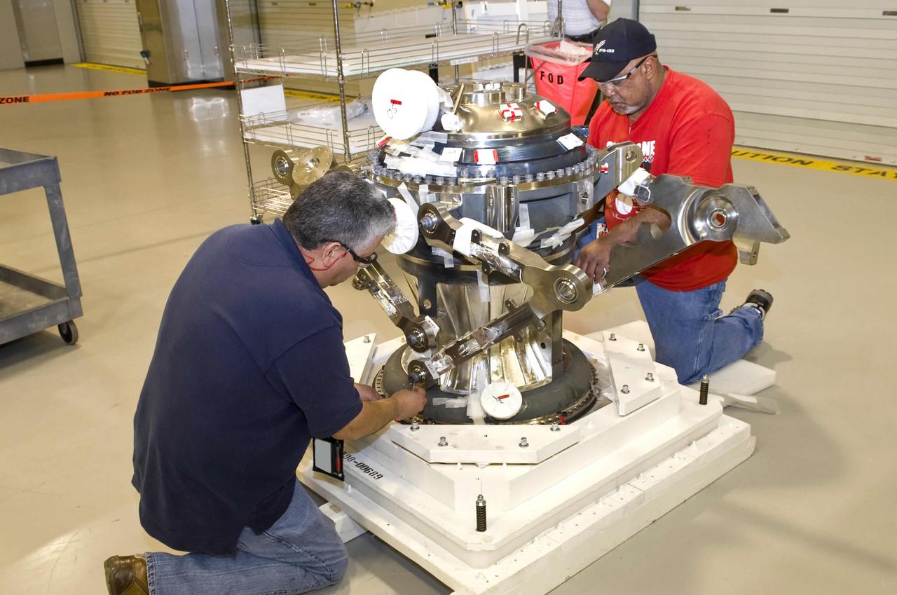
Pratt & Whitney Rocketdyne employees Carlos Alfaro (l) and Oliver Swanier work on the main combustion element of the J-2X rocket engine at their John C. Stennis Space Center facility. Assembly of the J-2X rocket engine to be tested at the site is under way, with completion and delivery to the A-2 Test Stand set for June. The J-2X is being developed as a next-generation engine that can carry humans into deep space. Stennis Space Center is preparing a trio of stands to test the new engine.

Pratt & Whitney Rocketdyne employees Carlos Alfaro (l) and Oliver Swanier work on the main combustion element of the J-2X rocket engine at their John C. Stennis Space Center facility. Assembly of the J-2X rocket engine to be tested at the site is under way, with completion and delivery to the A-2 Test Stand set for June. The J-2X is being developed as a next-generation engine that can carry humans into deep space. Stennis Space Center is preparing a trio of stands to test the new engine.
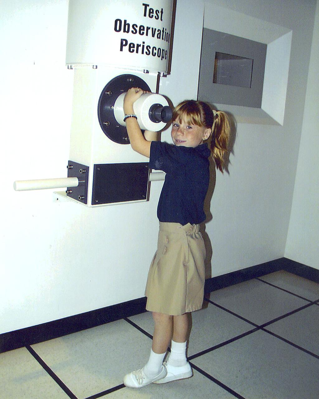
At the test observation periscope in the Test Control Center exhibit in StenniSphere at the John C. Stennis Space Center in Hancock County, Miss., visitors can observe a test of a Space Shuttle Main Engine exactly as test engineers might see it during a real engine test. The Test Control Center exhibit exactly simulates not only the test control environment, but also the procedure of testing a rocket engine. Designed to entertain while educating, StenniSphere includes informative dispays and exhibits from NASA's lead center for rocket propulsion and remote sensing applications. StenniSphere is open free of charge from 9 a.m. to 5 p.m. daily.
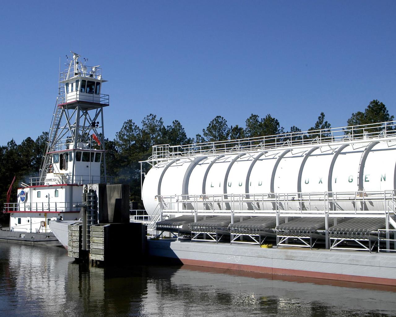
The crew of the NASA tugboat Clermont II navigates a barge of super-cool liquid oxygen through the 7 -mile canal system at SSC prior to a Space Shuttle Main Engine test.
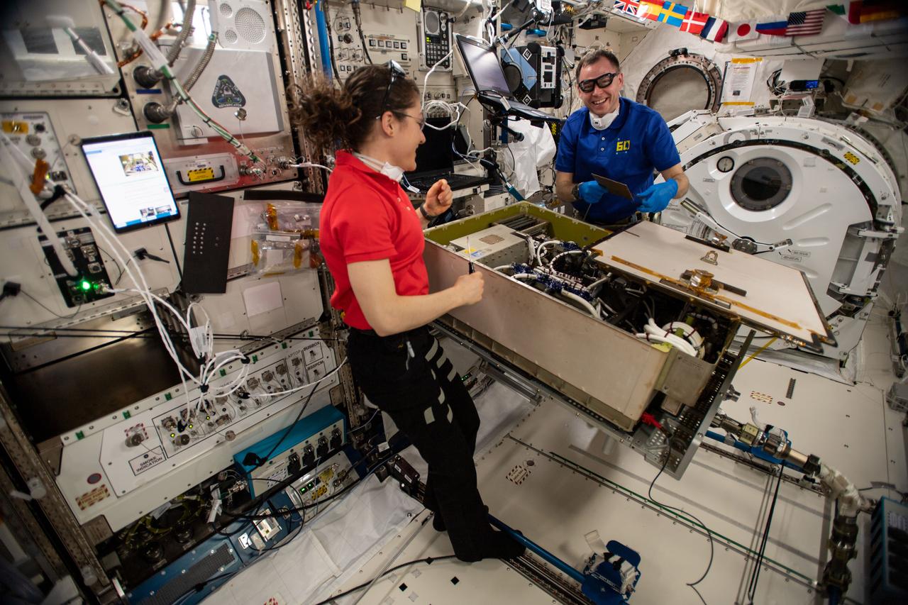
Expedition 60 flight engineers Christina Koch and Nick Hague of NASA work together on the Main Bus Switching Unit aboard the space station to replace a failed circuit card before performing a test to ensure its functionality.
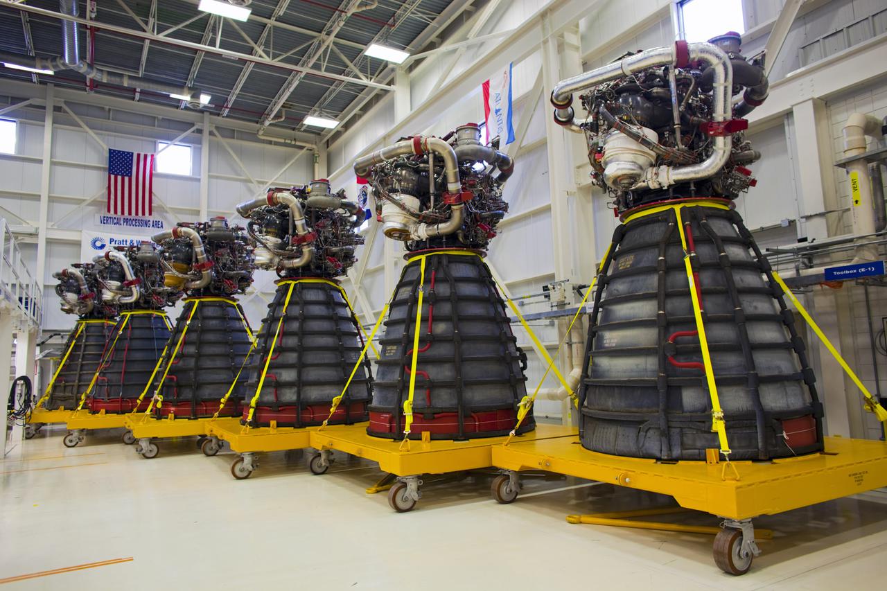
CAPE CANAVERAL, Fla. – At NASA’s Kennedy Space Center in Florida, all six Pratt Whitney Rocketdyne space shuttle main engines (SSMEs) from space shuttle Endeavour's STS-134 and space shuttle Atlantis' STS-135 missions sit in test cells inside the Engine Shop. For the first time, all 15 main engines are in the Engine Shop at the same time. They are being prepared for shipment to NASA's Stennis Space Center in Mississippi for storage following the completion of the Space Shuttle Program. The engines are being repurposed for use on NASA’s Space Launch System heavy lift rocket. Photo credit: NASA_Dimitri Gerondidakis
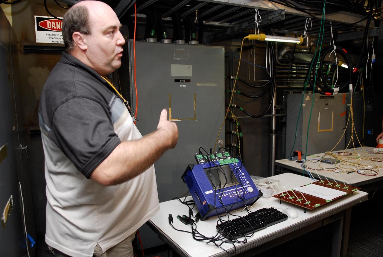
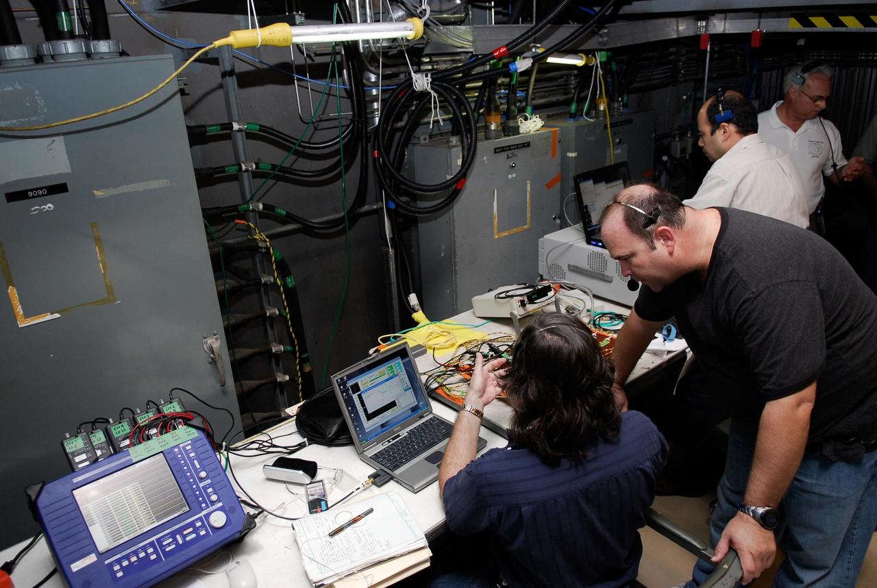
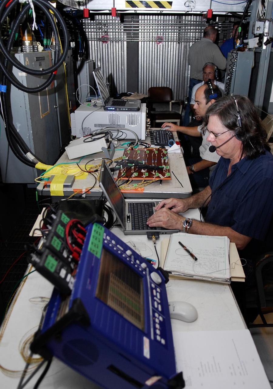
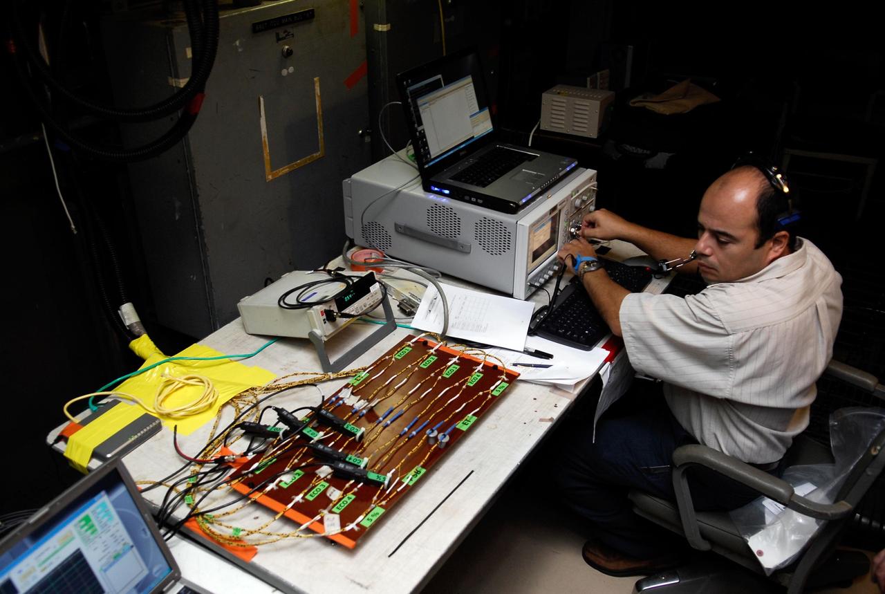
KENNEDY SPACE CENTER, FLA. -- On Launch Pad 39A, a technician explains how test equipment -- the blue monitor -- will be used to validate the circuit on test wiring from the electrical harness in space shuttle Atlantis' aft main engine compartment connected with the engine cut-off system. The test wiring leads from the tail mast on the mobile launcher platform to the interior where the Time Domain Reflectometry, or TDR, test equipment will be located to test the sensor system. Photo credit: NASA/Kim Shiflett
What better way to mark 50 years of rocket engine testing than with a rocket engine test? Stennis Space Center employees enjoyed a chance to view an RS-68 engine test at the B-1 Test Stand on April 19, almost 50 years to the day that the first test was conducted at the south Mississippi site in 1966. The test viewing was part of a weeklong celebration of the 50th year of rocket engine testing at Stennis. The first test at the site occurred April 23, 1966, with a 15-second firing of a Saturn V second stage prototype (S-II-C) on the A-2 Test Stand. The center subsequently tested Apollo rocket stages that carried humans to the moon and every main engine used to power 135 space shuttle missions. It currently tests engines for NASA’s new Space Launch System vehicle.
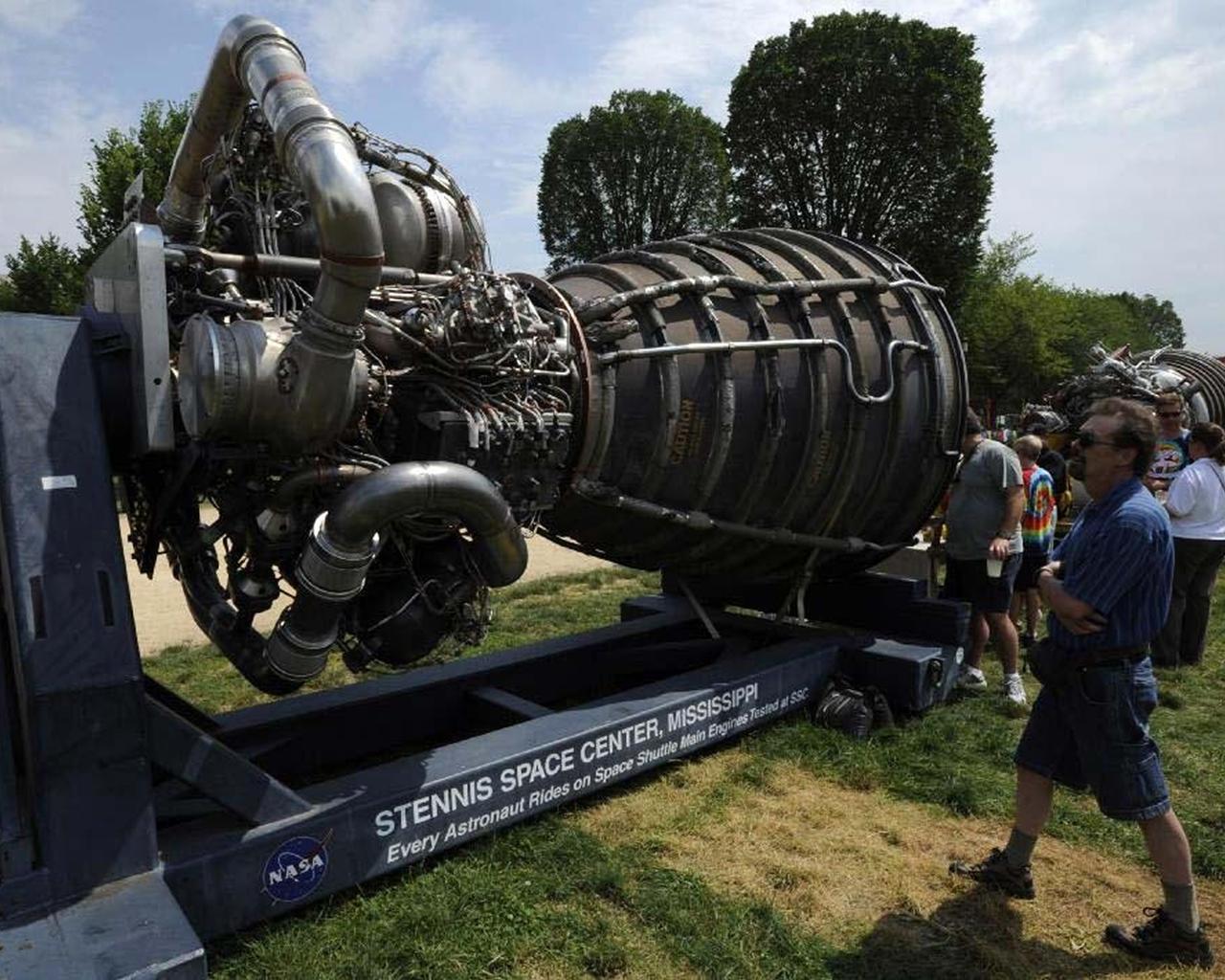
A visitor to the Smithsonian Folklife Festival in Washington, D.C., examines a space shuttle main engine display provided by Stennis Space Center. Since 1975, Stennis has been responsible for testing every engine used in NASA's Space Shuttle Program.
NASA engineers successfully tested a Russian-built rocket engine on November 4, 1998 at the Marshall Space Flight Center (MSFC) Advanced Engine Test Facility, which had been used for testing the Saturn V F-1 engines and Space Shuttle Main engines. The MSFC was under a Space Act Agreement with Lockheed Martin Astronautics of Denver to provide a series of test firings of the Atlas III propulsion system configured with the Russian-designed RD-180 engine. The tests were designed to measure the performance of the Atlas III propulsion system, which included avionics and propellant tanks and lines, and how these components interacted with the RD-180 engine. The RD-180 is powered by kerosene and liquid oxygen, the same fuel mix used in Saturn rockets. The RD-180, the most powerful rocket engine tested at the MSFC since Saturn rocket tests in the 1960s, generated 860,000 pounds of thrust.
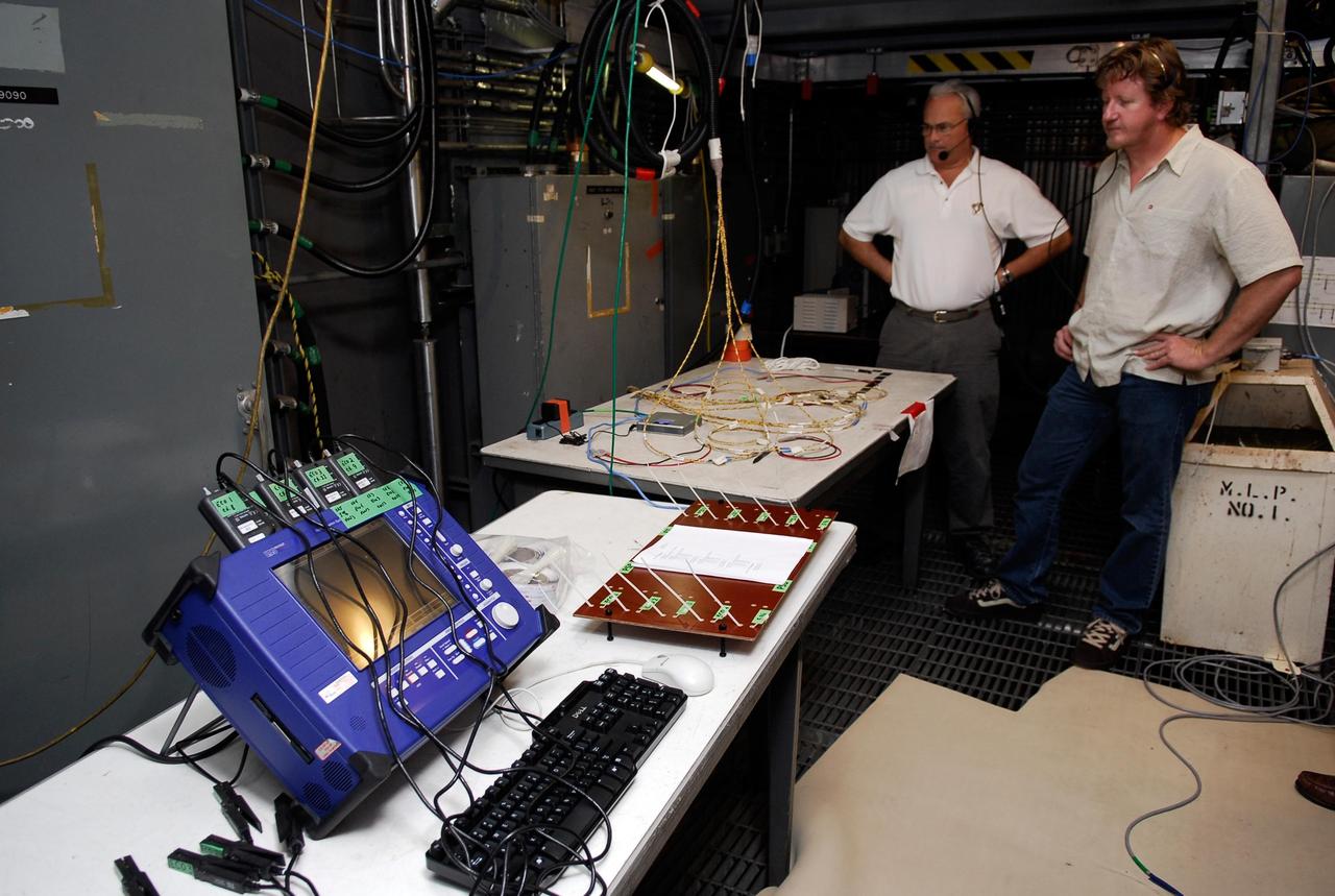
KENNEDY SPACE CENTER, FLA. -- On Launch Pad 39A, technicians overlook wires and monitoring equipment that will be used to validate the circuit on the test wiring from the electrical harness in space shuttle Atlantis' aft main engine compartment connected with the engine cut-off system. The test wiring leads from the tail mast on the mobile launcher platform to the interior where the Time Domain Reflectometry, or TDR, test equipment will be located to test the sensor system. Photo credit: NASA/Kim Shiflett
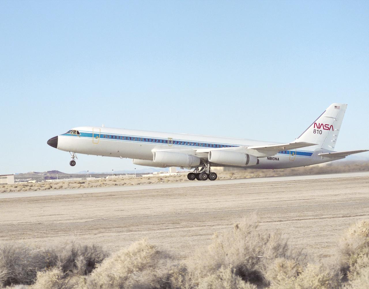
Taking off on a flight from NASA's Dryden Flight Research Center, Edwards, California, is NASA's Landing Systems Research Aircraft (LSRA), a modified Convair (CV) 990. A new landing gear test fixture representative of the shuttle's landing gear system had been installed in the lower fuselage of the CV-990 test aircraft between the aircraft's normal main landing gear. Following initial flights, static loads testing and calibration of the test gear were conducted at Dryden. Tests allowed engineers to assess the performance of the space shuttle's main and nose landing gear systems under varying conditions.
The Space Shuttle Main Engine (SSME) reached a historic milestone July 16, 2004, when a successful flight acceptance test was conducted at NASA Stennis Space Center (SSC). The engine tested today is the first complete engine to be tested and shipped in its entirety to Kennedy Space Center for installation on Space Shuttle Discovery for STS-114, NASA's Return to Flight mission. The engine test, which began about 3:59 p.m. CDT, ran for 520 seconds (8 minutes), the length of time it takes for the Space Shuttle to reach orbit.
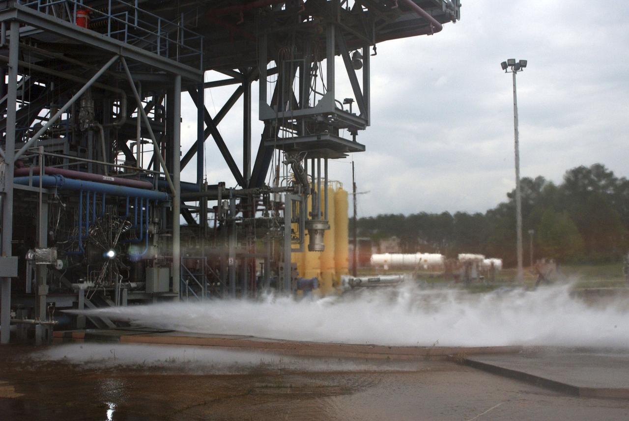
Gaseous hydrogen is burned off at the E1 Test Stand the night of Oct. 7 during a cold-flow test of the fuel turbopump of the Integrated Powerhead Demonstrator (IPD) at NASA Stennis Space Center (SSC). The gaseous hydrogen spins the pump's turbine during the test, which was conducted to verify the pump's performance. Engineers plan one more test before sending the pump to The Boeing Co. for inspection. It will then be returned to SSC for engine system assembly. The IPD is the first reusable hydrogen-fueled advanced engine in development since the Space Shuttle Main Engine.
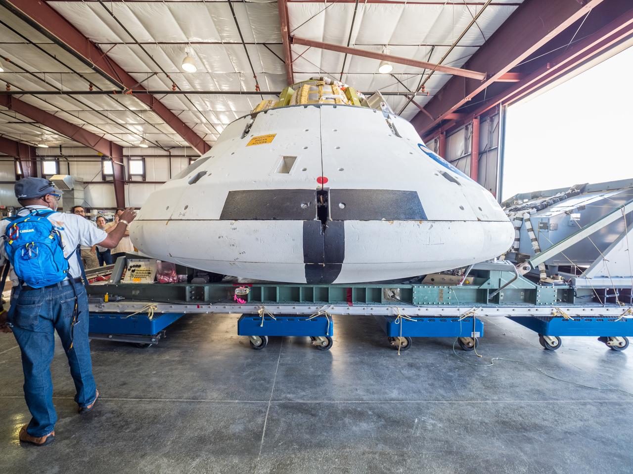
NASA engineers prepare for the test of the Orion spacecraft’s parachutes on Wednesday, Aug. 26 at the U.S. Army’s Yuma Proving Ground in Arizona on Aug. 24, 2015. An engineering model of the spacecraft will drop from an airplane 35,000 feet up to evaluate how it fares when the parachute system does not perform as expected...During the test, Orion engineers will carry out a scenario in which one of the spacecraft’s two drogue parachutes and one of its three main parachutes fail. This high-risk assessment is the penultimate drop test of the scheduled engineering evaluations leading up to next year’s tests to qualify the parachute system for crewed flights. Part of Batch image transfer from Flickr.
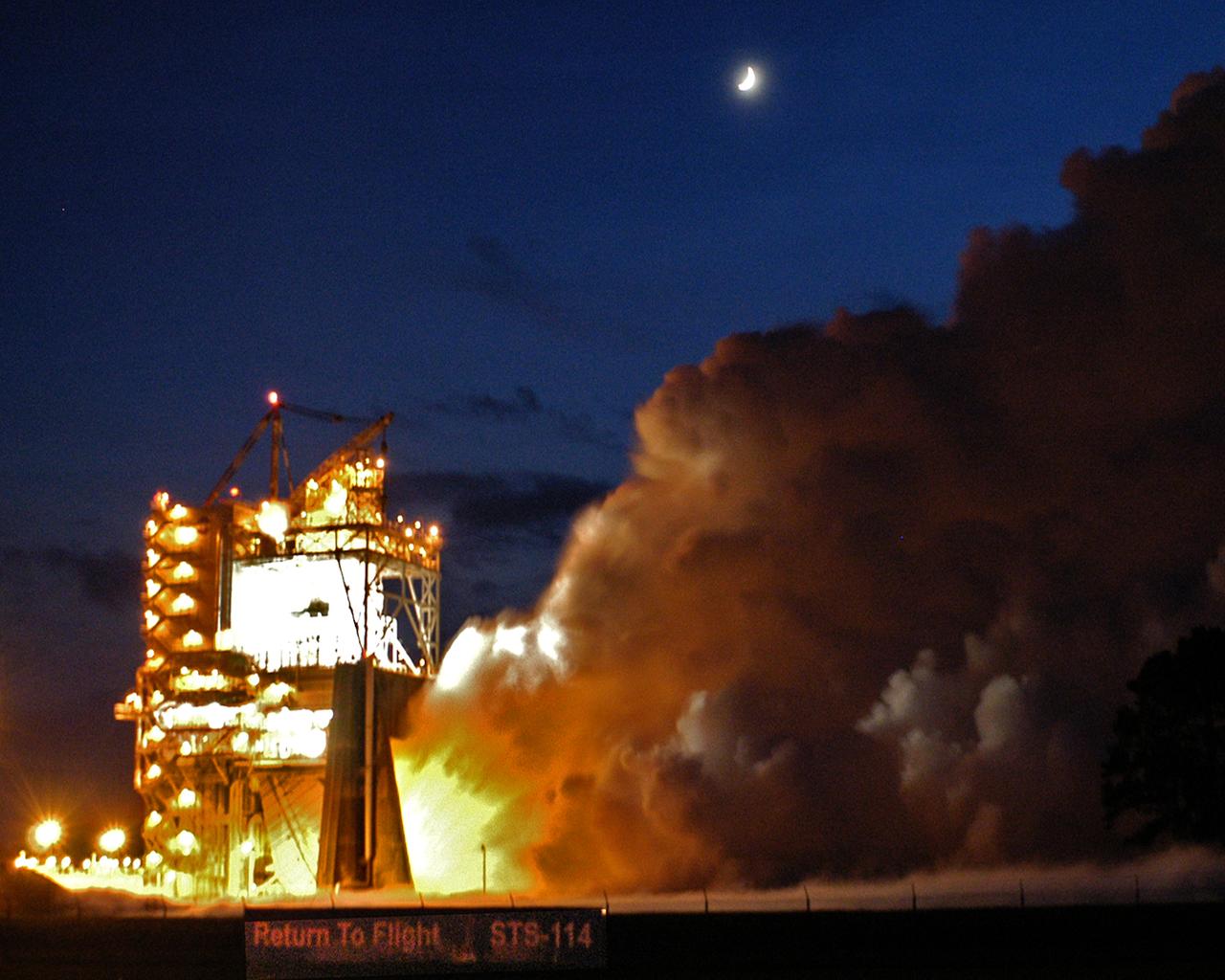
The Space Shuttle's Main Engine (SSME) reached another milestone Aug. 19, 2004, when a successful flight acceptance test was conducted at NASA Stennis Space Center (SSC). The engine tested was the final of three engines that will carry the next Space Shuttle into orbit. The engine will be shipped to NASA Kennedy Space Center in Florida for installation on Space Shuttle Discovery for STS-114, NASA's Return to Flight mission. The engine test, which began about 8:10 p.m. CDT, ran for 520 seconds (8 minutes), the length of time it takes for the Space Shuttle to reach orbit.

KENNEDY SPACE CENTER, FLA. -- On Launch Pad 39A at NASA's Kennedy Space Center, the wiring is checked and validated before the tanking test on space shuttle Atlantis' external tank set for Dec. 18. The test wiring has been spliced into an electrical harness in the aft main engine compartment connected with the engine cut-off, or ECO, sensor system. The attached wiring leads to the interior of the mobile launcher platform where the time domain reflectometry, or TDR, test equipment is located. Photo credit: NASA/Kim Shiflett
KENNEDY SPACE CENTER, FLA. -- On Launch Pad 39A at NASA's Kennedy Space Center, the wiring is checked and validated before the tanking test on space shuttle Atlantis' external tank set for Dec. 18. The test wiring has been spliced into an electrical harness in the aft main engine compartment connected with the engine cut-off, or ECO, sensor system. The attached wiring leads to the interior of the mobile launcher platform where the time domain reflectometry, or TDR, test equipment is located. Photo credit: NASA/Kim Shiflett
KENNEDY SPACE CENTER, FLA. -- On Launch Pad 39A at NASA's Kennedy Space Center, the wiring is checked and validated before the tanking test on space shuttle Atlantis' external tank set for Dec. 18. The test wiring has been spliced into an electrical harness in the aft main engine compartment connected with the engine cut-off, or ECO, sensor system. The attached wiring leads to the interior of the mobile launcher platform where the time domain reflectometry, or TDR, test equipment is located. Photo credit: NASA/Kim Shiflett
KENNEDY SPACE CENTER, FLA. -- On Launch Pad 39A at NASA's Kennedy Space Center, the wiring is checked and validated before the tanking test on space shuttle Atlantis' external tank set for Dec. 18. The test wiring has been spliced into an electrical harness in the aft main engine compartment connected with the engine cut-off, or ECO, sensor system. The attached wiring leads to the interior of the mobile launcher platform where the time domain reflectometry, or TDR, test equipment is located. Photo credit: NASA/Kim Shiflett
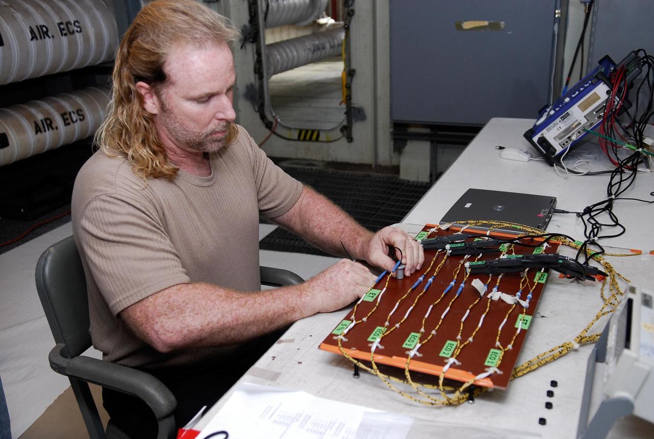
KENNEDY SPACE CENTER, FLA. -- On Launch Pad 39A at NASA's Kennedy Space Center, a technician sets up wiring for the tanking test on space shuttle Atlantis' external tank set for Dec. 18. The test wiring has been spliced into an electrical harness in the aft main engine compartment connected with the engine cut-off, or ECO, sensor system. The attached wiring leads to the interior of the mobile launcher platform where the time domain reflectometry, or TDR, test equipment is located. Photo credit: NASA/Kim Shiflett
KENNEDY SPACE CENTER, FLA. -- On Launch Pad 39A at NASA's Kennedy Space Center, the wiring is checked and validated before the tanking test on space shuttle Atlantis' external tank set for Dec. 18. The test wiring has been spliced into an electrical harness in the aft main engine compartment connected with the engine cut-off, or ECO, sensor system. The attached wiring leads to the interior of the mobile launcher platform where the time domain reflectometry, or TDR, test equipment is located. Photo credit: NASA/Kim Shiflett
CAPE CANAVERAL, Fla. -- In Orbiter Processing Facility-3 at NASA's Kennedy Space Center in Florida, space shuttle main engine No. 3 is installed in shuttle Discovery. The engine was removed to give technicians time to replace a suspect turbopump in main engine No. 1, which encountered an issue during torque testing. Discovery and its STS-133 crew are targeted to deliver the Express Logistics Carrier-4 filled with external payloads and experiments, as well as critical spare components to the International Space Station later this year. Photo credit: NASA_Jack Pfaller
This is a ground level view of Test Stand 500 at the east test area of the Marshall Space Flight Center. Originally constructed in 1966, Test Stand 500 is a multipurpose, dual-position test facility. The stand was utilized to test liquid hydrogen/liquid oxygen turbopumps and combustion devices for the J-2 engine. One test position has a high superstructure with lines and tankage for testing liquid hydrogen and liquid oxygen turbopumps while the other position is adaptable to pressure-fed test programs such as turbo machinery bearings or seals. The facility was modified in 1980 to support Space Shuttle main engine (SSME) bearing testing.
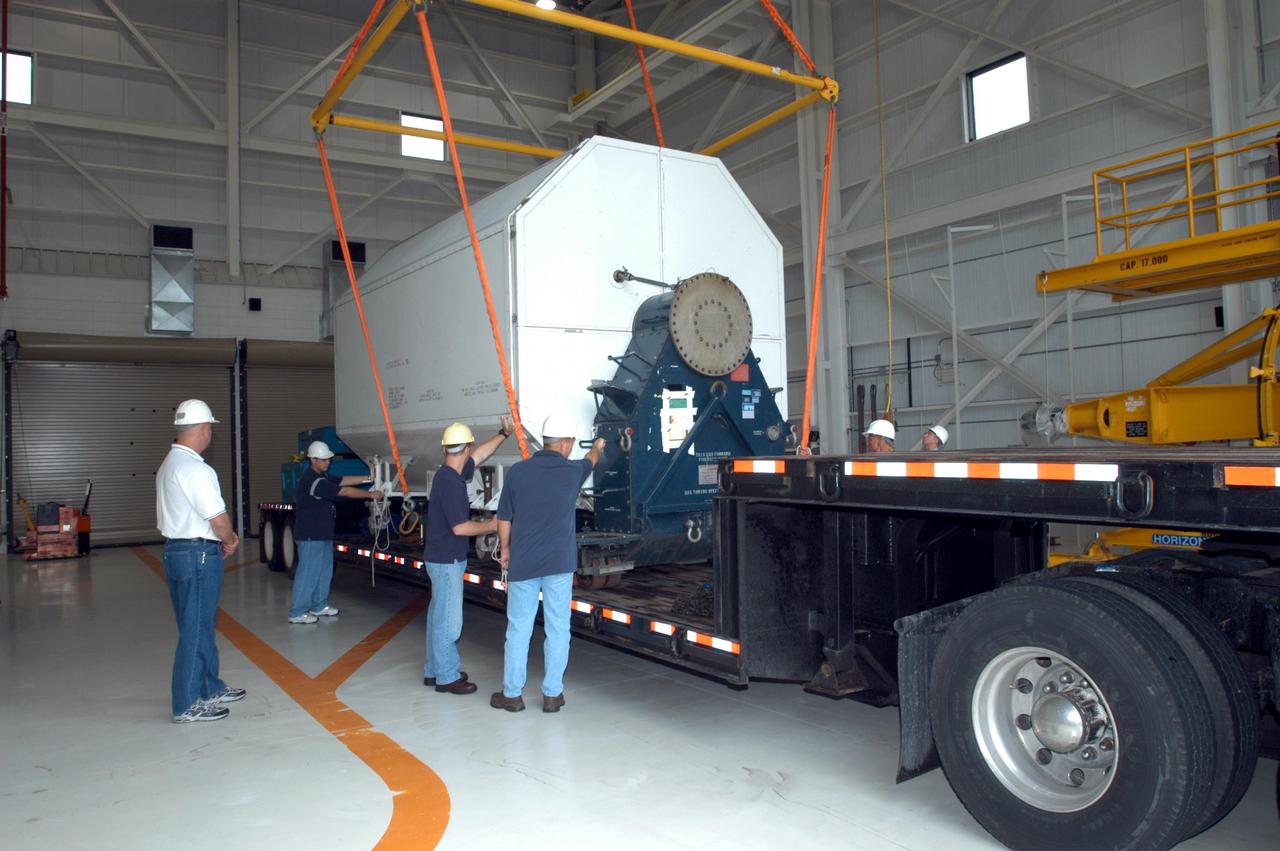
KENNEDY SPACE CENTER, FLA. - Inside the KSC Engine Shop, Boeing-Rocketdyne technicians attach an overhead crane to the container enclosing the third Space Shuttle Main Engine for Discovery’s Return to Flight mission STS-114 arrives at the KSC Engine Shop aboard a trailer. The engine is returning from NASA’s Stennis Space Center in Mississippi where it underwent a hot fire acceptance test. Typically, the engines are installed on an orbiter in the Orbiter Processing Facility approximately five months before launch.
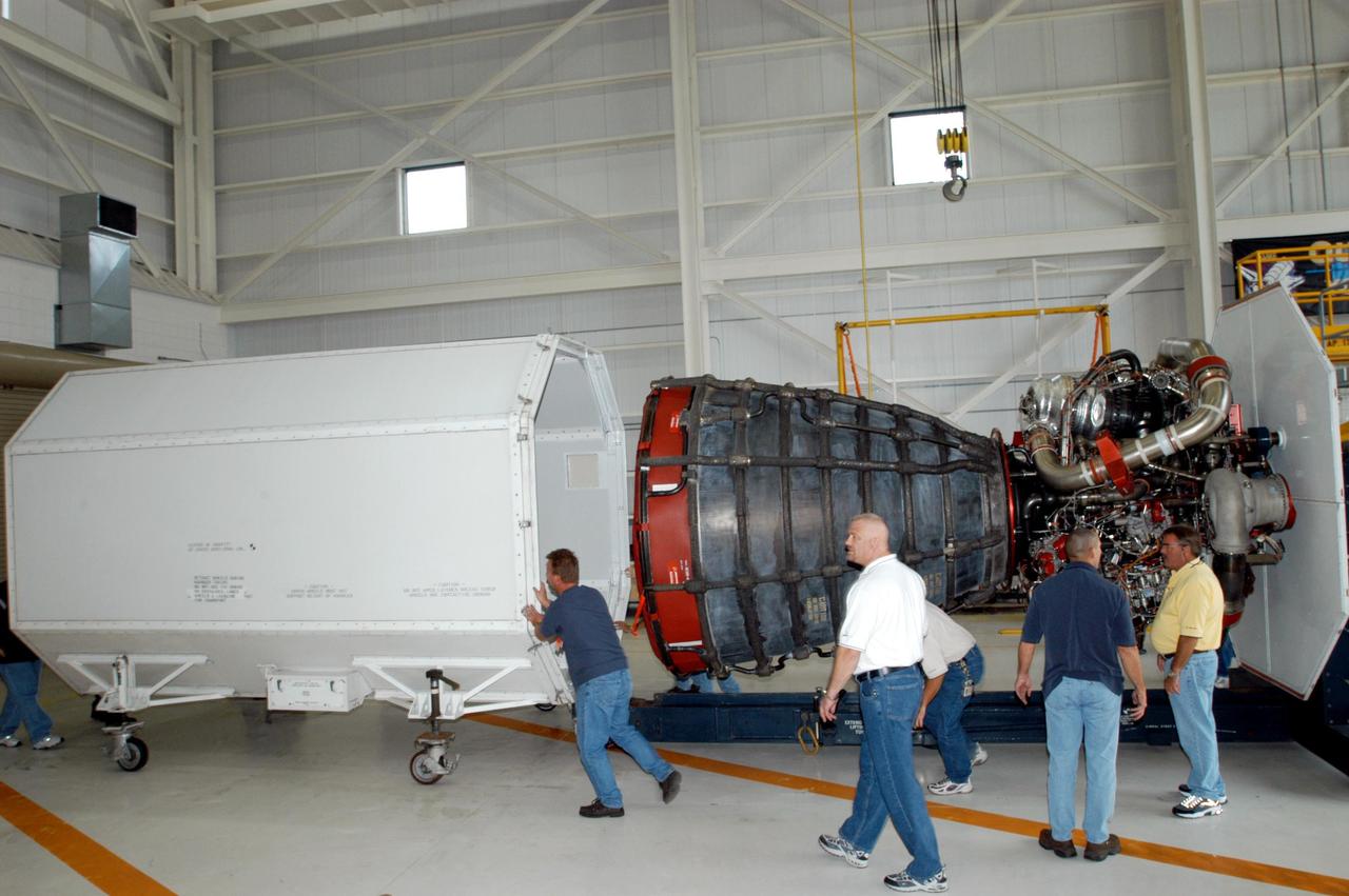
KENNEDY SPACE CENTER, FLA. - Inside the KSC Engine Shop, Boeing-Rocketdyne technicians remove the container that enclosed the third Space Shuttle Main Engine for Discovery’s Return to Flight mission STS-114. The engine is returning from NASA’s Stennis Space Center in Mississippi where it underwent a hot fire acceptance test. Typically, the engines are installed on an orbiter in the Orbiter Processing Facility approximately five months before launch.
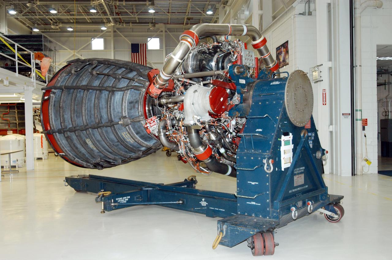
KENNEDY SPACE CENTER, FLA. - Inside the KSC Engine Shop, the third Space Shuttle Main Engine for Discovery’s Return to Flight mission STS-114 is secure on a stand. The engine has been returned from NASA’s Stennis Space Center in Mississippi where it underwent a hot fire acceptance test. Typically, the engines are installed on an orbiter in the Orbiter Processing Facility approximately five months before launch.
KENNEDY SPACE CENTER, FLA. - Enclosed inside the shipping container, the third Space Shuttle Main Engine for Discovery’s Return to Flight mission STS-114 arrives at the KSC Engine Shop aboard a trailer. The engine is returning from NASA’s Stennis Space Center in Mississippi where it underwent a hot fire acceptance test. Typically, the engines are installed on an orbiter in the Orbiter Processing Facility approximately five months before launch.
KENNEDY SPACE CENTER, FLA. - Inside the KSC Engine Shop, the third Space Shuttle Main Engine for Discovery’s Return to Flight mission STS-114 is ready to be lifted off the trailer. The engine is returning from NASA’s Stennis Space Center in Mississippi where it underwent a hot fire acceptance test. Typically, the engines are installed on an orbiter in the Orbiter Processing Facility approximately five months before launch.
KENNEDY SPACE CENTER, FLA. - Inside the KSC Engine Shop, Boeing-Rocketdyne technicians begin removing the end of the container enclosing the third Space Shuttle Main Engine for Discovery’s Return to Flight mission STS-114. The engine is returning from NASA’s Stennis Space Center in Mississippi where it underwent a hot fire acceptance test. Typically, the engines are installed on an orbiter in the Orbiter Processing Facility approximately five months before launch.
KENNEDY SPACE CENTER, FLA. - Inside the KSC Engine Shop, Boeing-Rocketdyne technicians secure on a stand the third Space Shuttle Main Engine for Discovery’s Return to Flight mission STS-114. The engine is returning from NASA’s Stennis Space Center in Mississippi where it underwent a hot fire acceptance test. Typically, the engines are installed on an orbiter in the Orbiter Processing Facility approximately five months before launch.

KENNEDY SPACE CENTER, FLA. - Patricia Slinger (left), a test engineer, and Monica Hagley, an avionics test engineer, look at a replacement orbiter point sensor chassis. Components are being tested to determine why one of the four liquid hydrogen tank low-level fuel cut-off sensors failed in a routine prelaunch check during the launch countdown July 13. The failure caused mission managers to scrub Discovery's first launch attempt. The sensor protects the Shuttle's main engines by triggering their shutdown in the event fuel runs unexpectedly low. The sensor is one of four inside the liquid hydrogen section of the External Tank (ET).
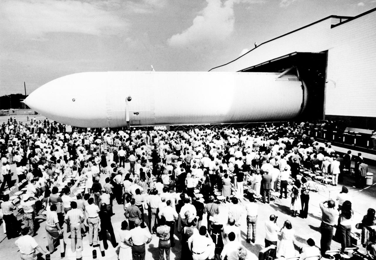
The first Space Shuttle External Tank, the Main Propulsion Test Article (MPTA), rolls off the assembly line September 9, 1977 at the Michoud Assembly Facility in New Orleans. The MPTA was then transported to the National Space Technology Laboratories in southern Mississippi where it was used in the first static firing of the three main engines. Marshall Space Flight Center had management responsibility for Space Shuttle propulsion elements, including the External Tank. Martin Marietta was the prime contractor who designed and assembled the tanks at Michoud.
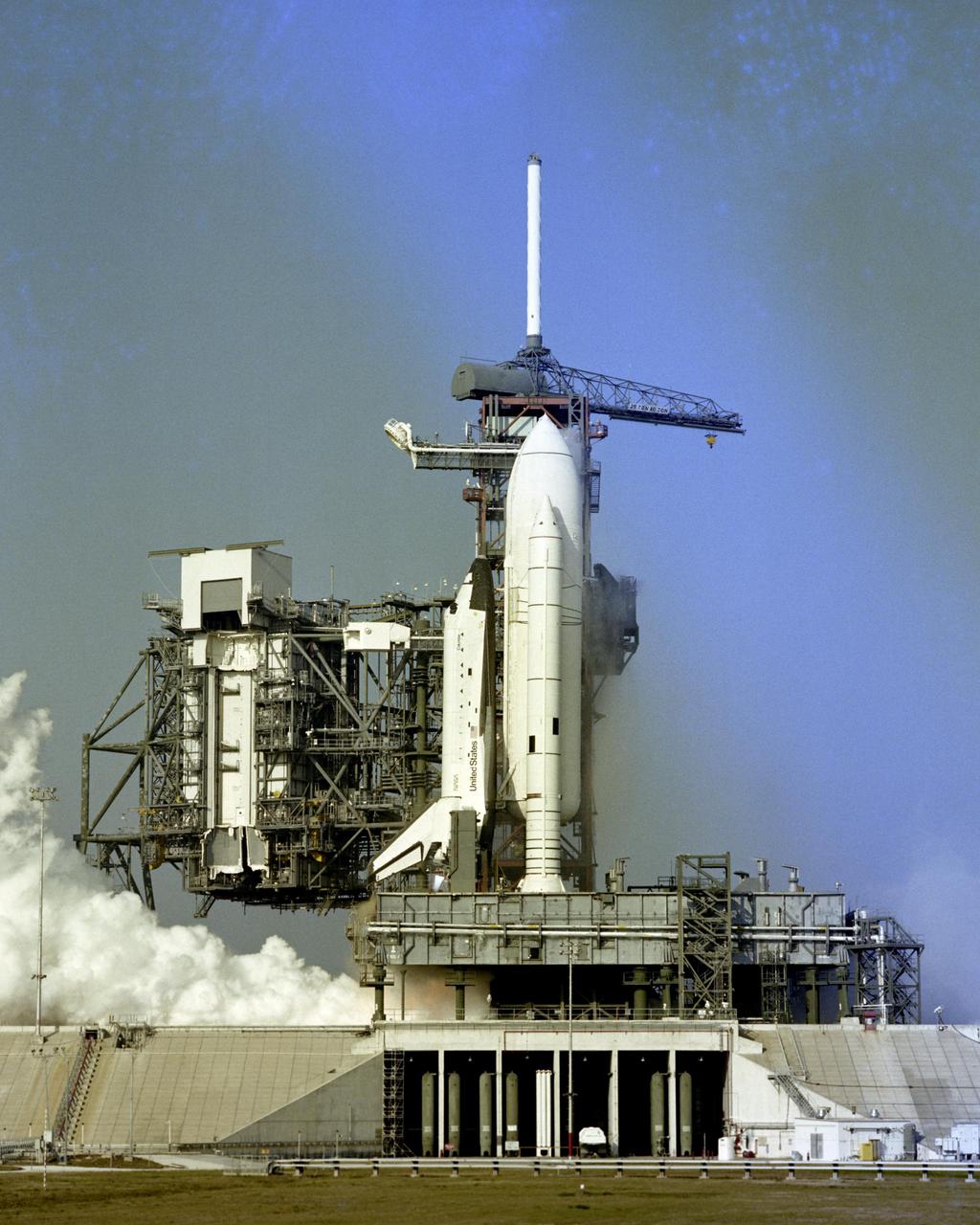
KENNEDY SPACE CENTER, FLA. - Flames shoot from the nozzles of Space Shuttle Columbia's three main engines during the successful 20-second static firing which capped a formal rehearsal for the maiden flight of Columbia, scheduled for early April. Remotely operated cameras inside the pad perimeter snapped closeup views of the milestone event, which took place at 8:45 a.m. on February 20, 1981. The three main engines reached 100 percent power -- over 1 million pounds of thrust -- during the test. Hold-down bolts secured the vehicle to its mobile launcher platform.
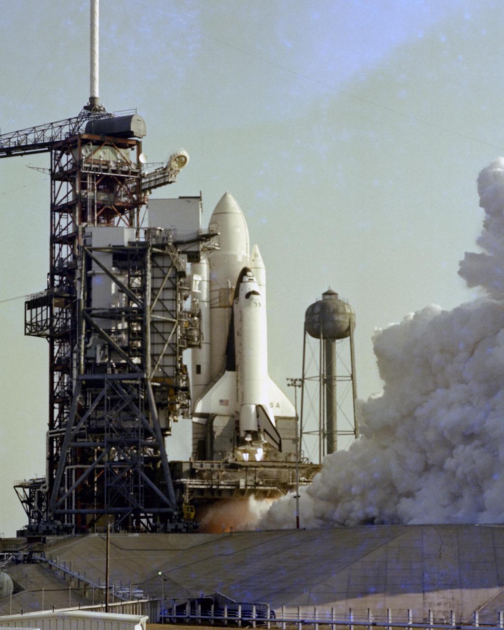
KENNEDY SPACE CENTER, FLA. - Flames shoot from the nozzles of Space Shuttle Columbia's three main engines during the successful 20-second static firing which capped a formal rehearsal for the maiden flight of Columbia, scheduled for early April. Remotely-operated cameras inside the pad perimeter snapped closeup views of the milestone event, which took place at 8:45 a.m. on February 20, 1981. The three main engines reach 100 percent power -- over 1 million pounds of thrust -- during the test. Hold-down bolts secured the vehicle to its mobile launcher platform.
Chosen to power the upper stages of the new Ares I Crew Launch Vehicle (CLV) and the Ares V cargo segment, the J-2X engine is a stepped up version of the hydrogen/oxygen-fuelled Apollo-era J-2 engine. It was developed for NASA by Pratt & Whitney Rocketdyne (PWR), a business unit of United Technologies Corporation of Canoga Park, California. As seen in this photograph, the engine underwent a series of hot fire tests, performed on sub scale main injector hardware in the Test Stand 116 at Marshall Space Flight Center (MSFC). The injector is a major component of the engine that injects and mixes propellants in the combustion chamber, where they are ignited and burned to produce thrust.
Chosen to power the upper stages of the new Ares I Crew Launch Vehicle (CLV) and the Ares V cargo segment, the J-2X engine is a stepped up version of the hydrogen/oxygen-fuelled Apollo-era J-2 engine. It was developed for NASA by Pratt & Whitney Rocketdyne (PWR), a business unit of United Technologies Corporation of Canoga Park, California. As seen in this photograph, the engine underwent a series of hot fire tests, performed on sub scale main injector hardware in the Test Stand 116 at Marshall Space Flight Center (MSFC). The injector is a major component of the engine that injects and mixes propellants in the combustion chamber, where they are ignited and burned to produce thrust.

Stennis Space Center Director Patrick Scheuermann welcomes Roy S. Estess family members and guests May 2 to the ceremony dedicating and naming the main NASA administration building for the late Stennis director. Estess served as director of the rocket engine test facility from 1989 to 2002.
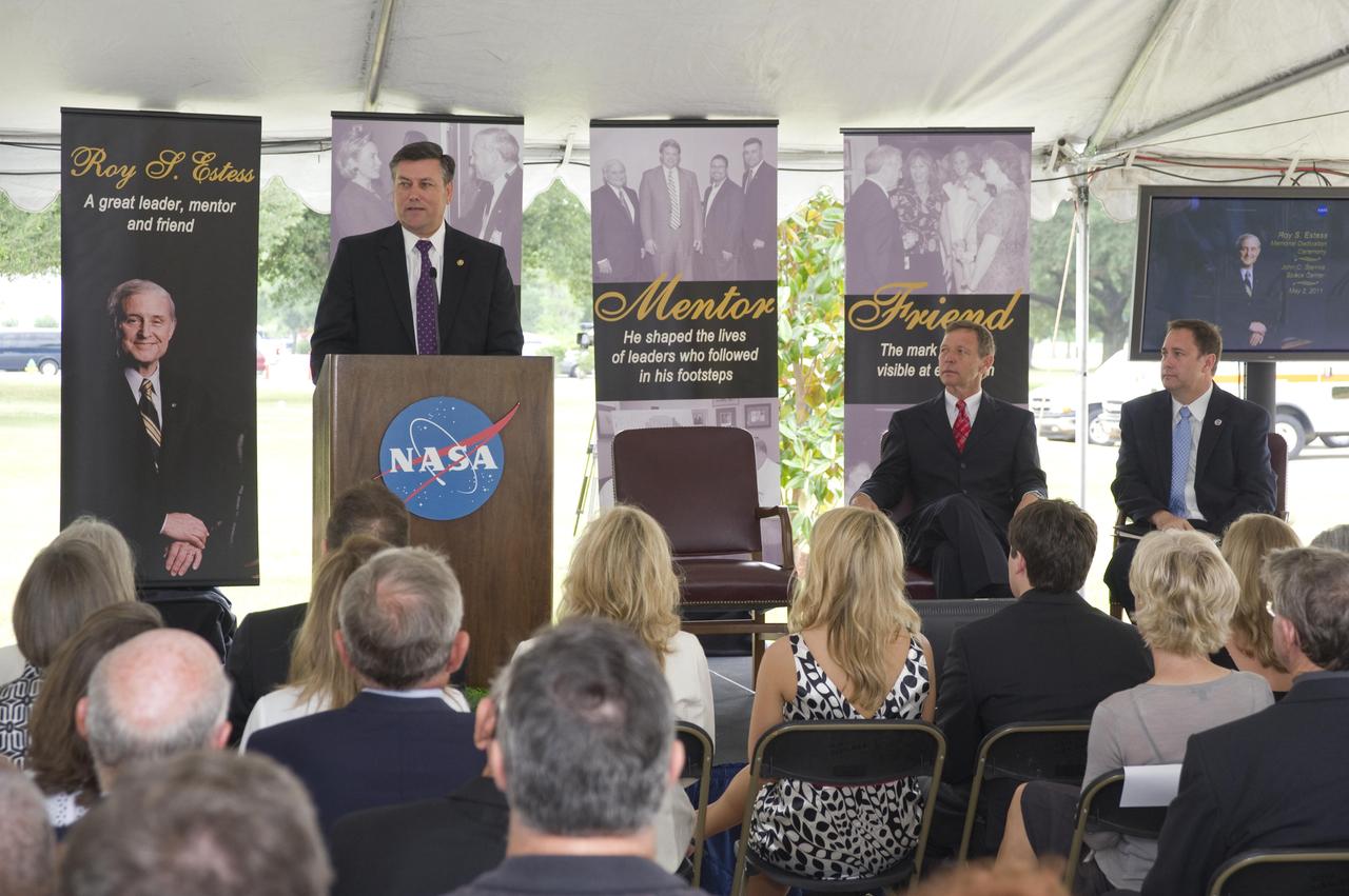
Stennis Space Center Director Patrick Scheuermann welcomes Roy S. Estess family members and guests May 2 to the ceremony dedicating and naming the main NASA administration building for the late Stennis director. Estess served as director of the rocket engine test facility from 1989 to 2002.

Stennis Space Center Director Gene Goldman (r to l) presents a commemorative photo of a space shuttle main engine test firing to STS-119 Mission Commander Lee Archambault, Pilot Tony Antonelli and Mission Specialists Steve Swanson and Richard Arnold during the crew's May 5 visit to the facility.
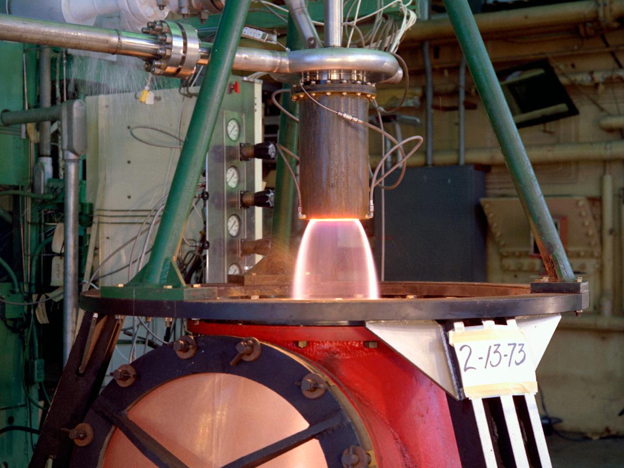
The thrust stand in the Rocket Engine Test Facility at the National Aeronautics and Space Administration (NASA) Lewis Research Center in Cleveland, Ohio. The Rocket Engine Test Facility was constructed in the mid-1950s to expand upon the smaller test cells built a decade before at the Rocket Laboratory. The $2.5-million Rocket Engine Test Facility could test larger hydrogen-fluorine and hydrogen-oxygen rocket thrust chambers with thrust levels up to 20,000 pounds. Test Stand A, seen in this photograph, was designed to fire vertically mounted rocket engines downward. The exhaust passed through an exhaust gas scrubber and muffler before being vented into the atmosphere. Lewis researchers in the early 1970s used the Rocket Engine Test Facility to perform basic research that could be utilized by designers of the Space Shuttle Main Engines. A new electronic ignition system and timer were installed at the facility for these tests. Lewis researchers demonstrated the benefits of ceramic thermal coatings for the engine’s thrust chamber and determined the optimal composite material for the coatings. They compared the thermal-coated thrust chamber to traditional unlined high-temperature thrust chambers. There were more than 17,000 different configurations tested on this stand between 1973 and 1976. The Rocket Engine Test Facility was later designated a National Historic Landmark for its role in the development of liquid hydrogen as a propellant.
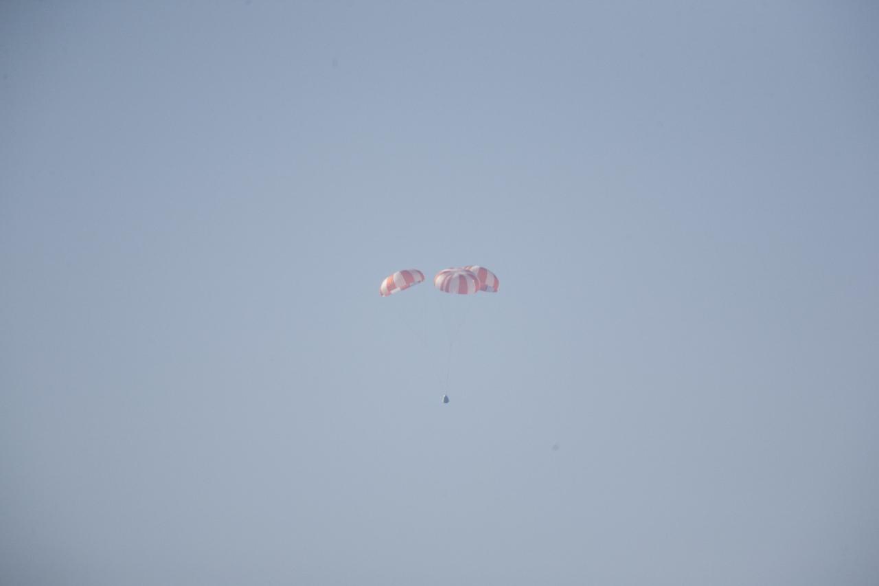
MORRO BAY, Calif. – The SpaceX main parachutes control the descent of the Dragon test article following a test over the Pacific Ocean, off the coast of Morro Bay, Calif. The test enabled SpaceX engineers to evaluate the spacecraft's parachute deployment system as part of a milestone under its Commercial Crew Integrated Capability agreement with NASA's Commercial Crew Program. The parachute test took place at Marro Bay, Calif. Photo credit: NASA/Kim Shiflett
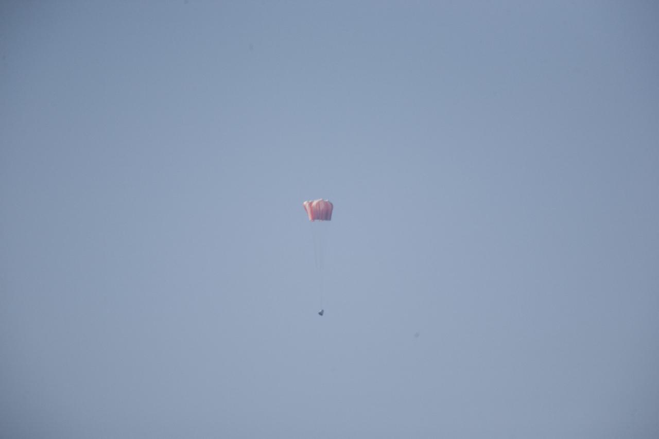
MORRO BAY, Calif. – The main parachutes open above a the Dragon test article during a test over the Pacific Ocean, off the coast of Morro Bay, Calif. The test enabled SpaceX engineers to evaluate the spacecraft's parachute deployment system as part of a milestone under its Commercial Crew Integrated Capability agreement with NASA's Commercial Crew Program. The parachute test took place at Marro Bay, Calif. Photo credit: NASA/Kim Shiflett
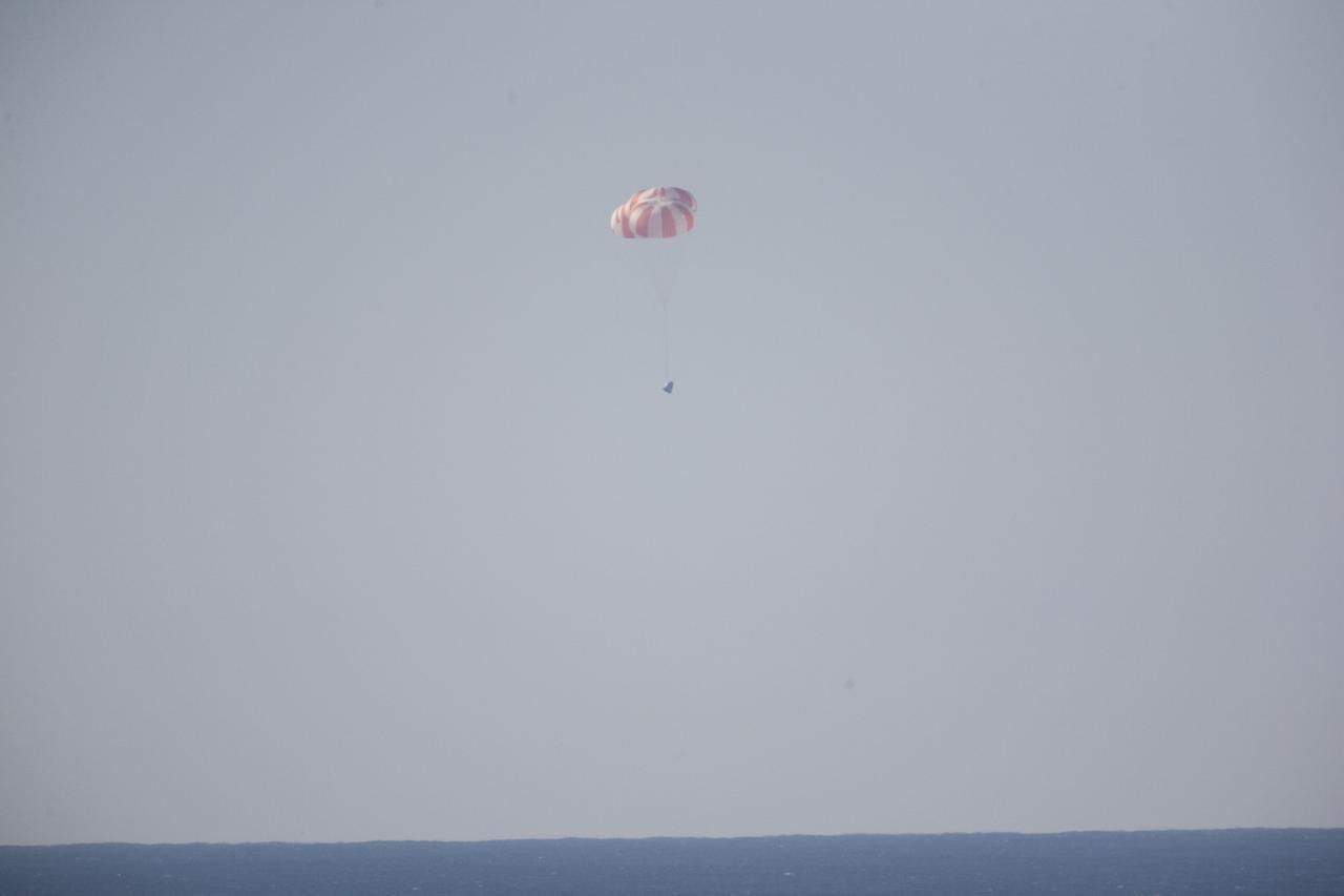
MORRO BAY, Calif. – The SpaceX main parachutes control the descent of the Dragon test article following a test over the Pacific Ocean, off the coast of Morro Bay, Calif. The test enabled SpaceX engineers to evaluate the spacecraft's parachute deployment system as part of a milestone under its Commercial Crew Integrated Capability agreement with NASA's Commercial Crew Program. The parachute test took place at Marro Bay, Calif. Photo credit: NASA/Kim Shiflett

MORRO BAY, Calif. – The SpaceX main parachutes control the descent of the Dragon test article following a test over the Pacific Ocean, off the coast of Morro Bay, Calif. The test enabled SpaceX engineers to evaluate the spacecraft's parachute deployment system as part of a milestone under its Commercial Crew Integrated Capability agreement with NASA's Commercial Crew Program. The parachute test took place at Marro Bay, Calif. Photo credit: NASA/Kim Shiflett
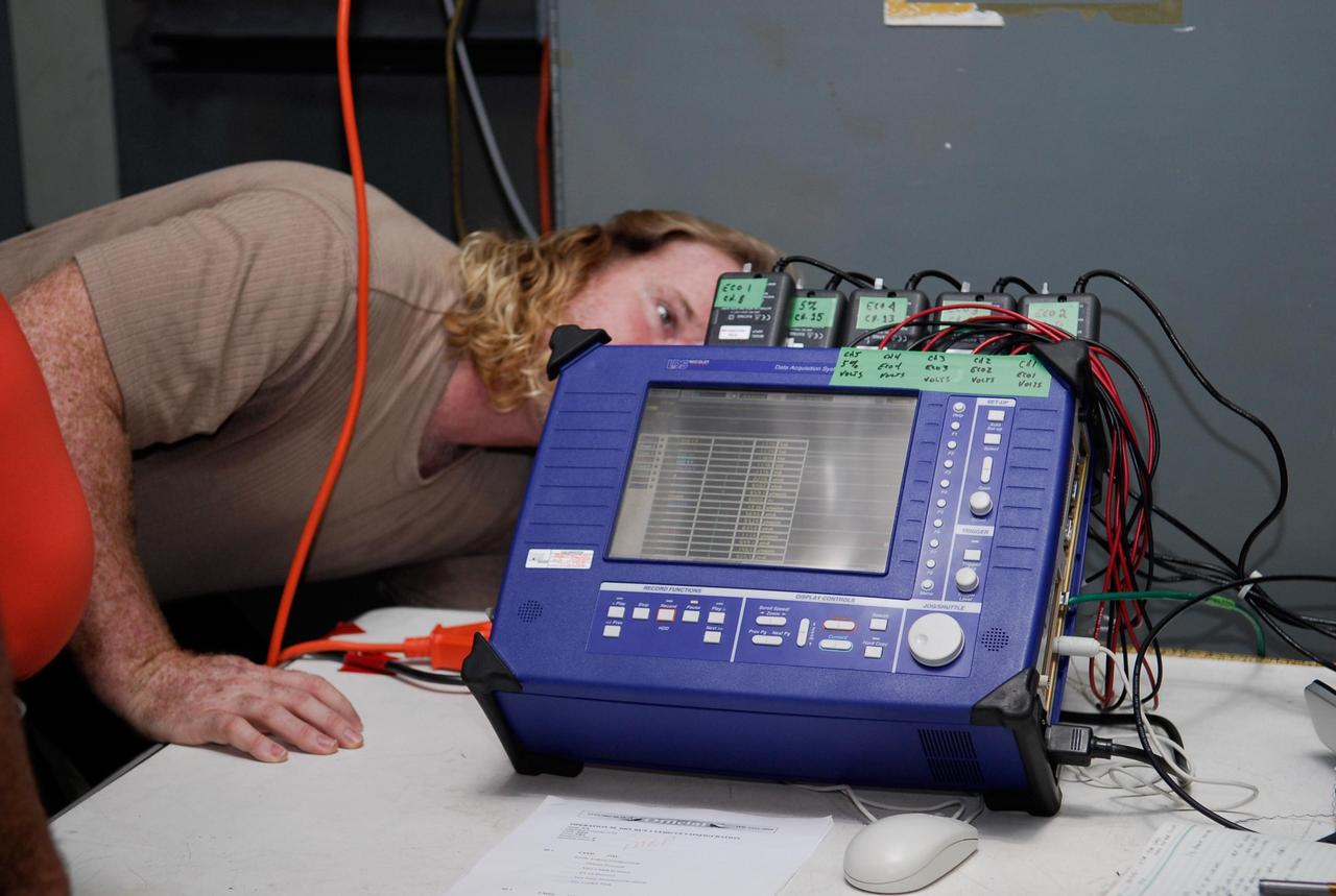
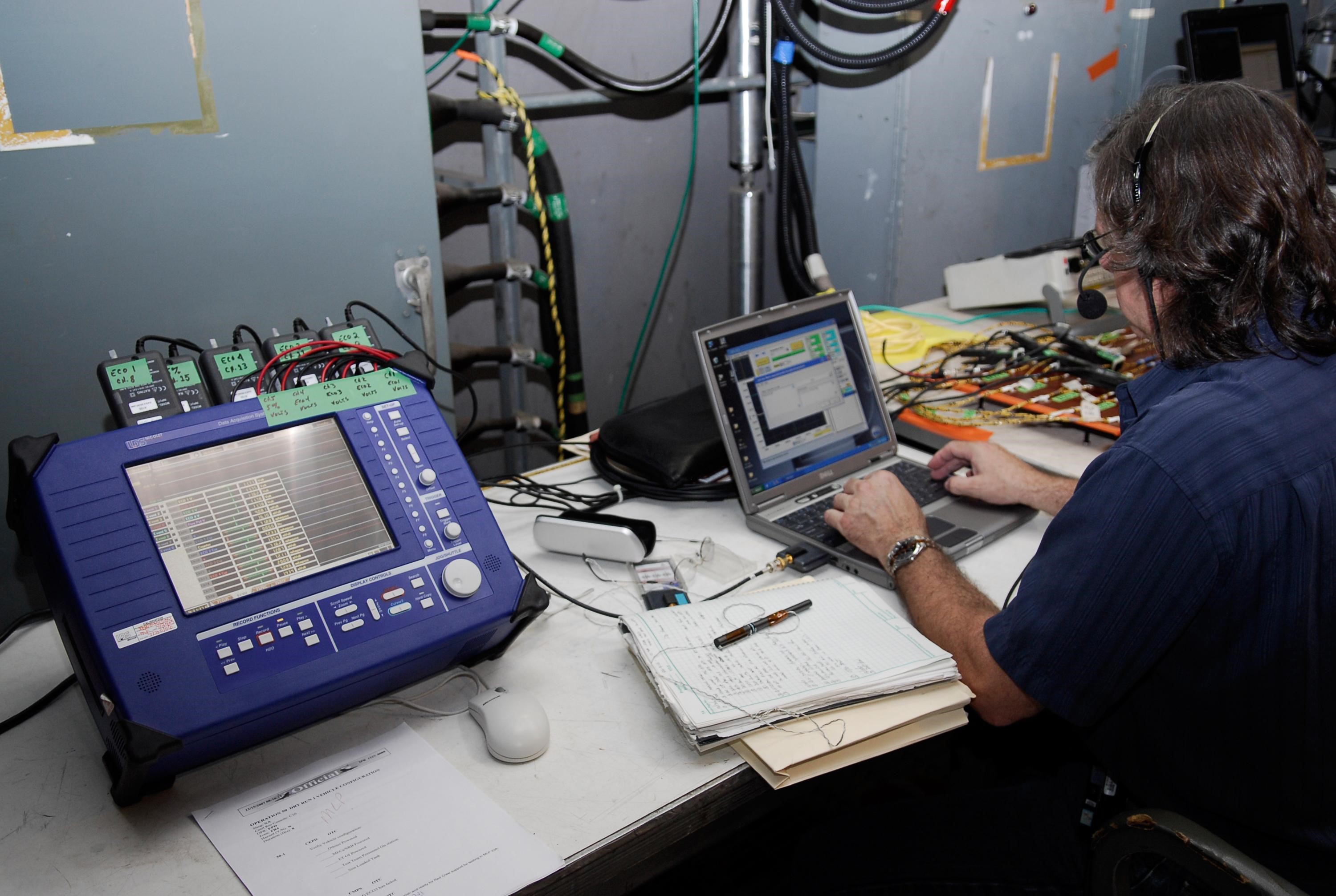
KENNEDY SPACE CENTER, FLA. -- On Launch Pad 39A at NASA's Kennedy Space Center, a technician checks the blue monitor that will be used to validate the circuit on test wiring during the tanking test on space shuttle Atlantis' external tank. The test wiring has been spliced into an electrical harness in the aft main engine compartment connected with the engine cut-off, or ECO, sensor system. The attached wiring leads to the interior of the mobile launcher platform where the time domain reflectometry, or TDR, test equipment is located. Photo credit: NASA/Kim Shiflett
KENNEDY SPACE CENTER, FLA. - The third Space Shuttle Main Engine (SSME) arrives in the Orbiter Processing Facility for installation on Discovery. Discovery is designated as the Return to Flight vehicle for mission STS-114. Recent improvements to the SSME include the introduction of redesigned high-pressure turbopumps into the SSME fleet. The new pumps are designed and built by Pratt and Whitney at West Palm Beach, Fla. SSMEs and the Pratt and Whitney turbopumps are tested at Stennis Space Center in Mississippi. Engines and engine components are delivered to Kennedy Space Center to be prepared for flight.