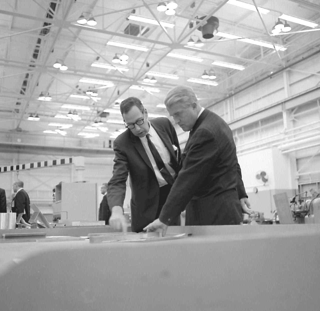
Dr. von Braun examining a welding device during the tour of the MSFC Manufacturing and Engineering (ME) Laboratory on October 17, 1967.
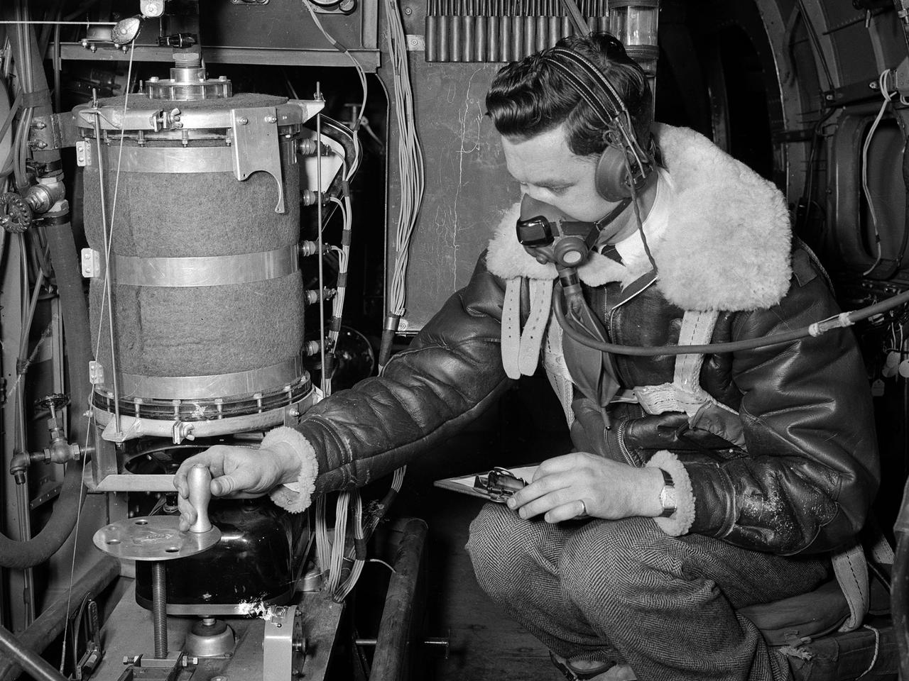
During his tenure as Director of the Marshall Space Flight Center (MSFC), Dr. von Braun enjoyed personally touring the Center's many space-related laboratories and facilities. This photo taken about 1961 shows him examining a test set up in the Center's Manufacturing Engineering Laboratory.
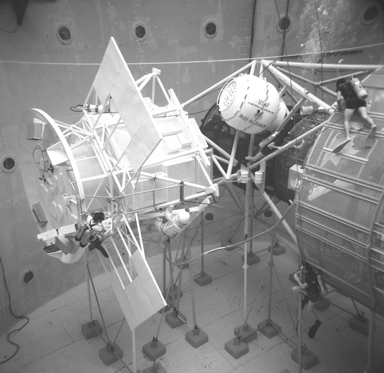
Dr. von Braun tried out a floating platform in the Marshall Space Flight Center Manufacturing Engineering Laboratory. This was a test rig to help determine how future astronauts will be able to perform maintenance tasks in the weightlessness in space. This photograph is believed to have been taken in 1961.
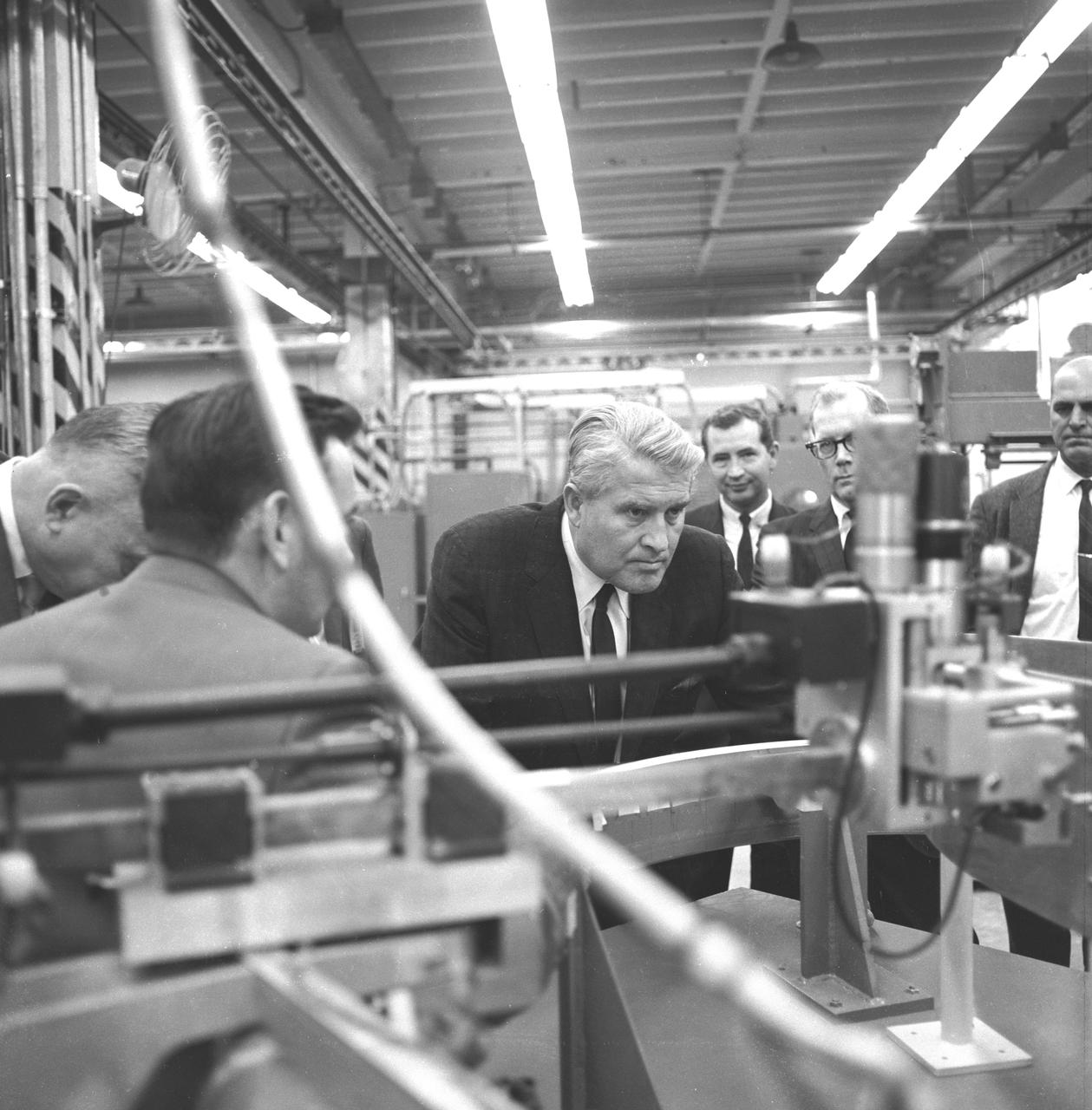
Dr. von Braun encouraged his laboratory directors and other managers at the Marshall Space Flight Center (MSFC) to adopt a "hands-on" approach to managing the technical challenges they confronted in developing the Saturn rockets for the Marned Lunar Landing Program. He is shown here asking a question about welding in an MSFC manufacturing and engineering laboratory. This photograph was made on or about October 17, 1967.
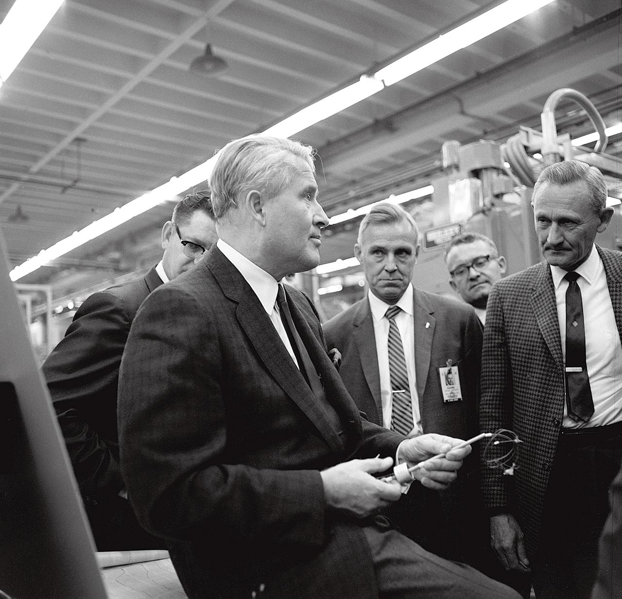
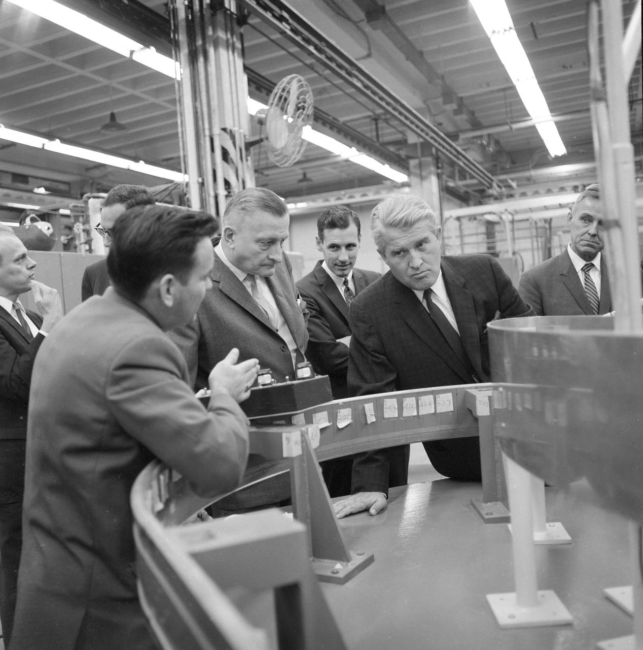
Dr. von Braun, Director of the Marshall Space Flight Center, listens attentively to a briefing on the metal forming techniques by Dr. Mathias Siebel of the Manufacturing and Engineering Laboratory at MSFC on October 17, 1967.
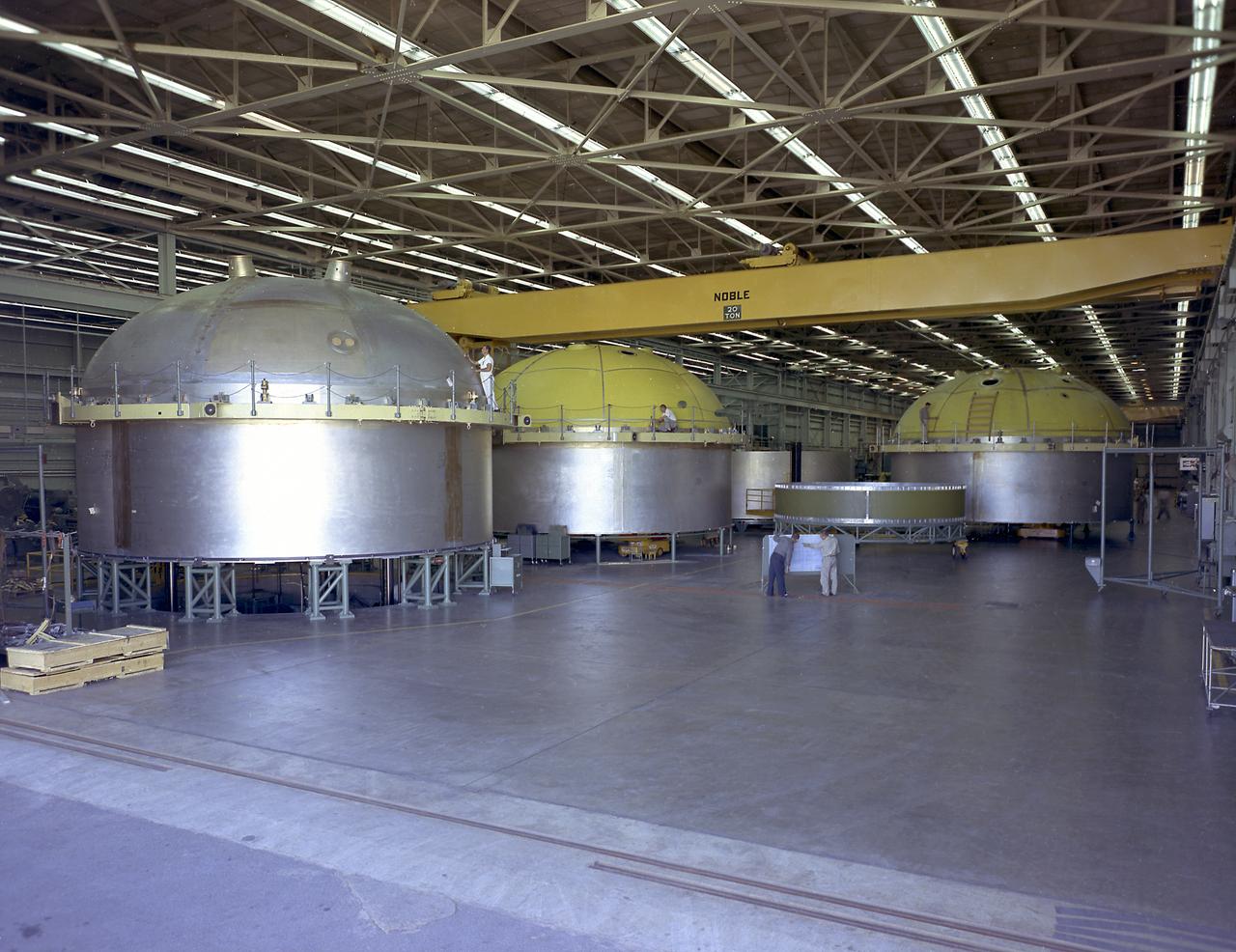
This photograph depicts engineers and technicians moving the Saturn V S-IC (First) stage liquid oxygen (LOX) tank from the Manufacturing Engineering Laboratory for load testing under simulated firing loads at the Propulsion and Vehicle Engineering Laboratory at the Marshall Space Flight Center.
Dr. von Braun, Dr. Weidner, and Ed Weaver examining a welding device during a tour of the MSFC Manufacturing and Engineering (ME) Laboratory on October 17, 1967.
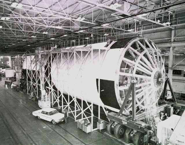
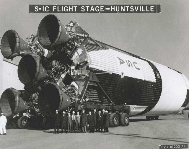
This photograph shows a Saturn V first stage (S-1C). This stage was assembled at the Manufacturing Engineering Laboratory at NASA's Marshall Space Flight Center. With assistance by the Boeing Company, the manufacturer, this first stage was assembled using components made by Boeing in Wichita, Kansas and New Orleans.
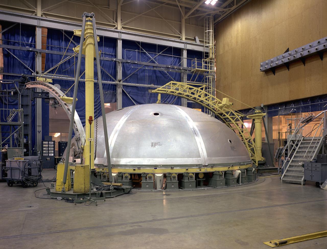
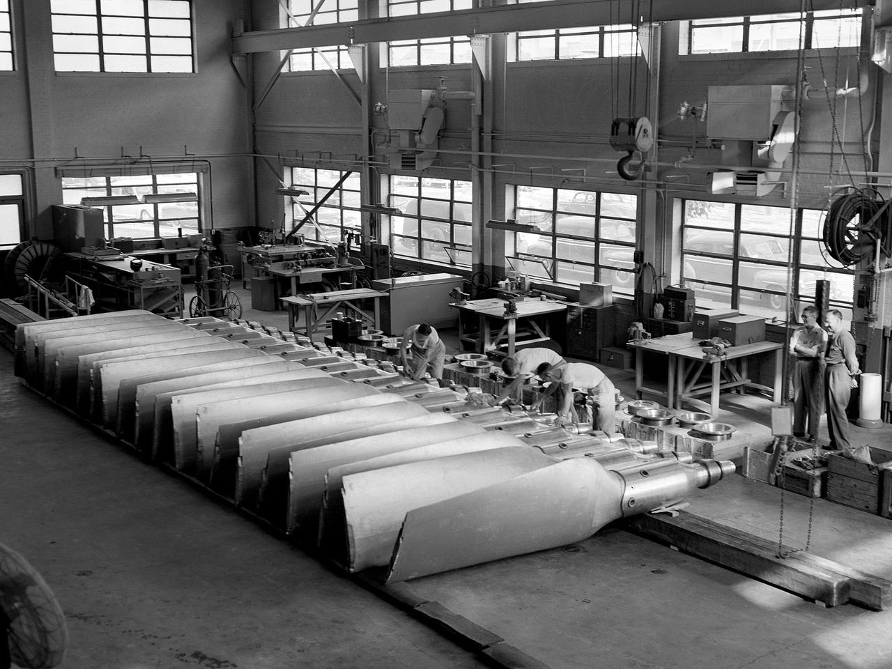
This photograph shows a bulkhead for the Saturn V S-IC stage fuel tank being fabricated at the Manufacturing Engineering Laboratory, building 4704, at the Marshall Space Flight Center.
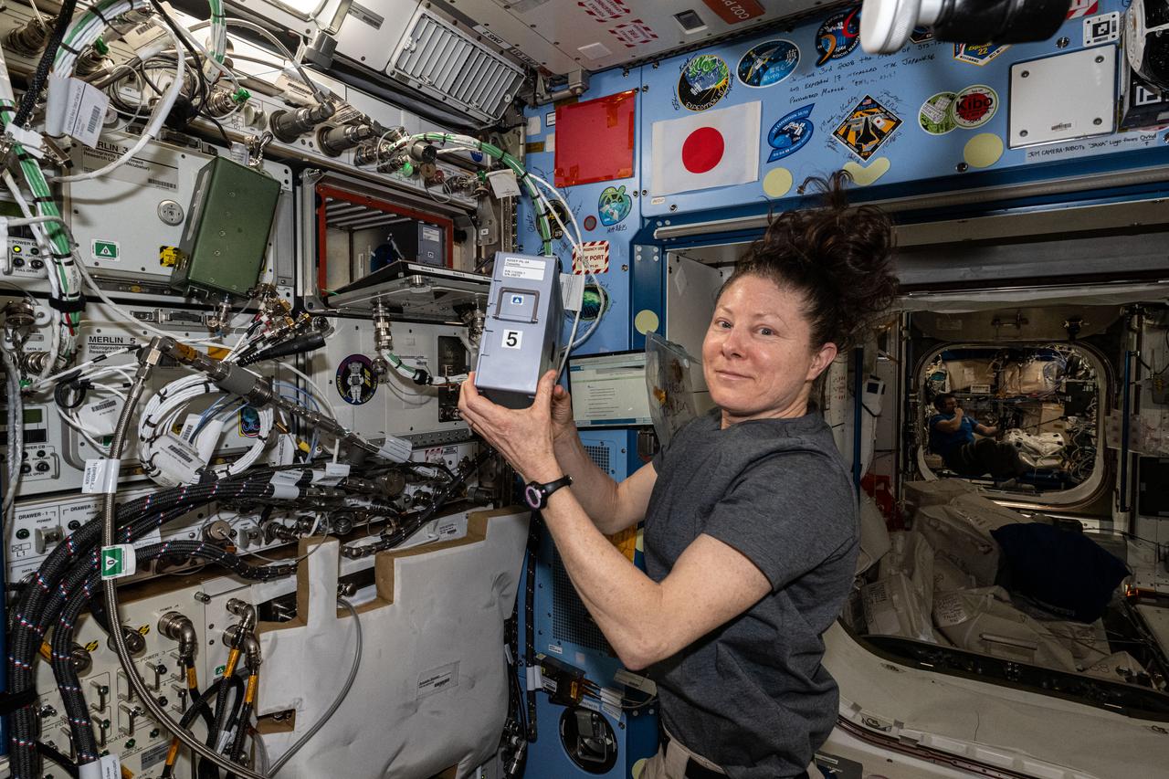
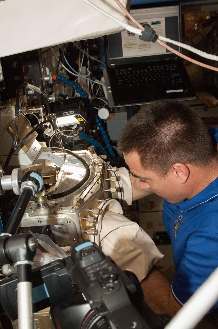
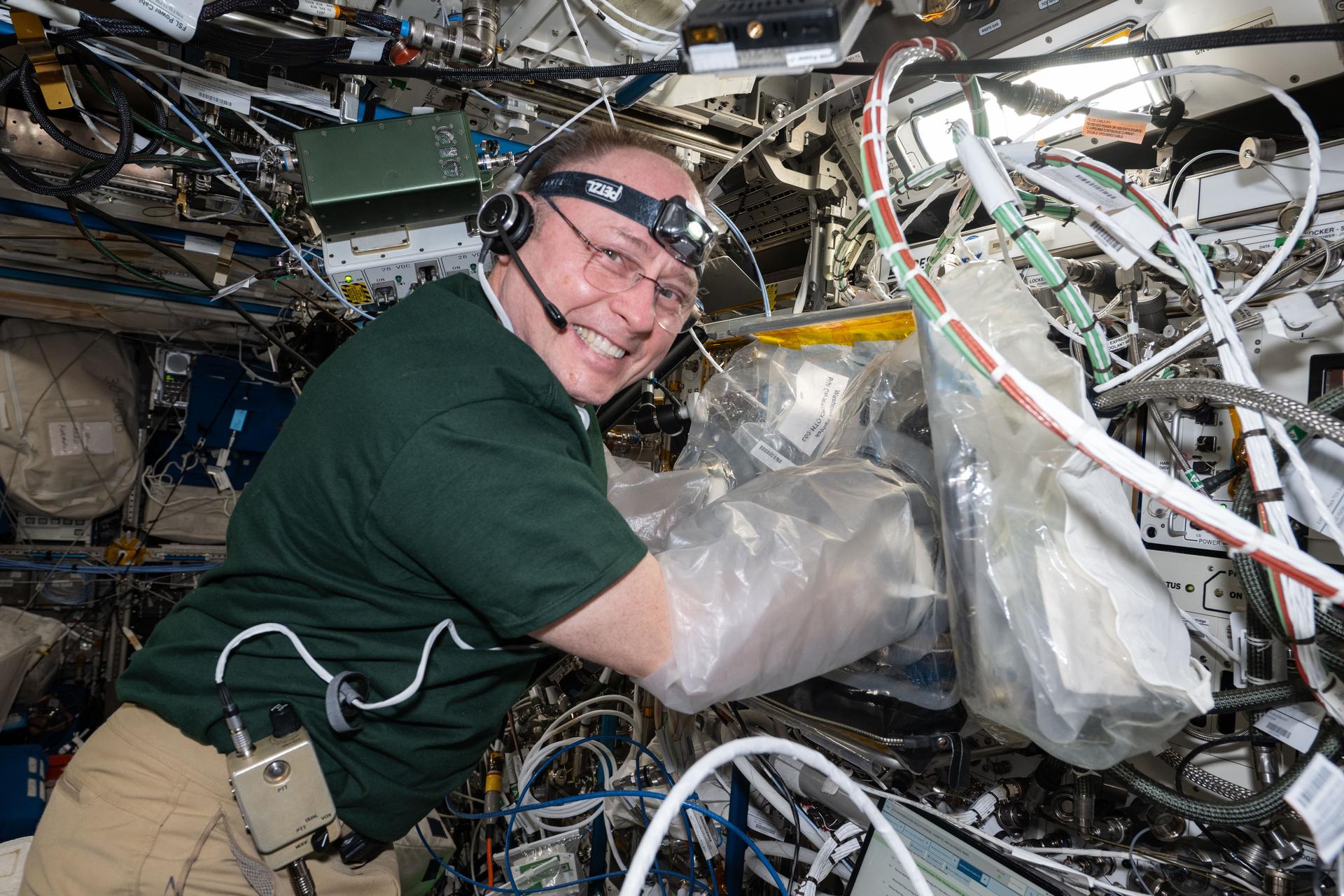
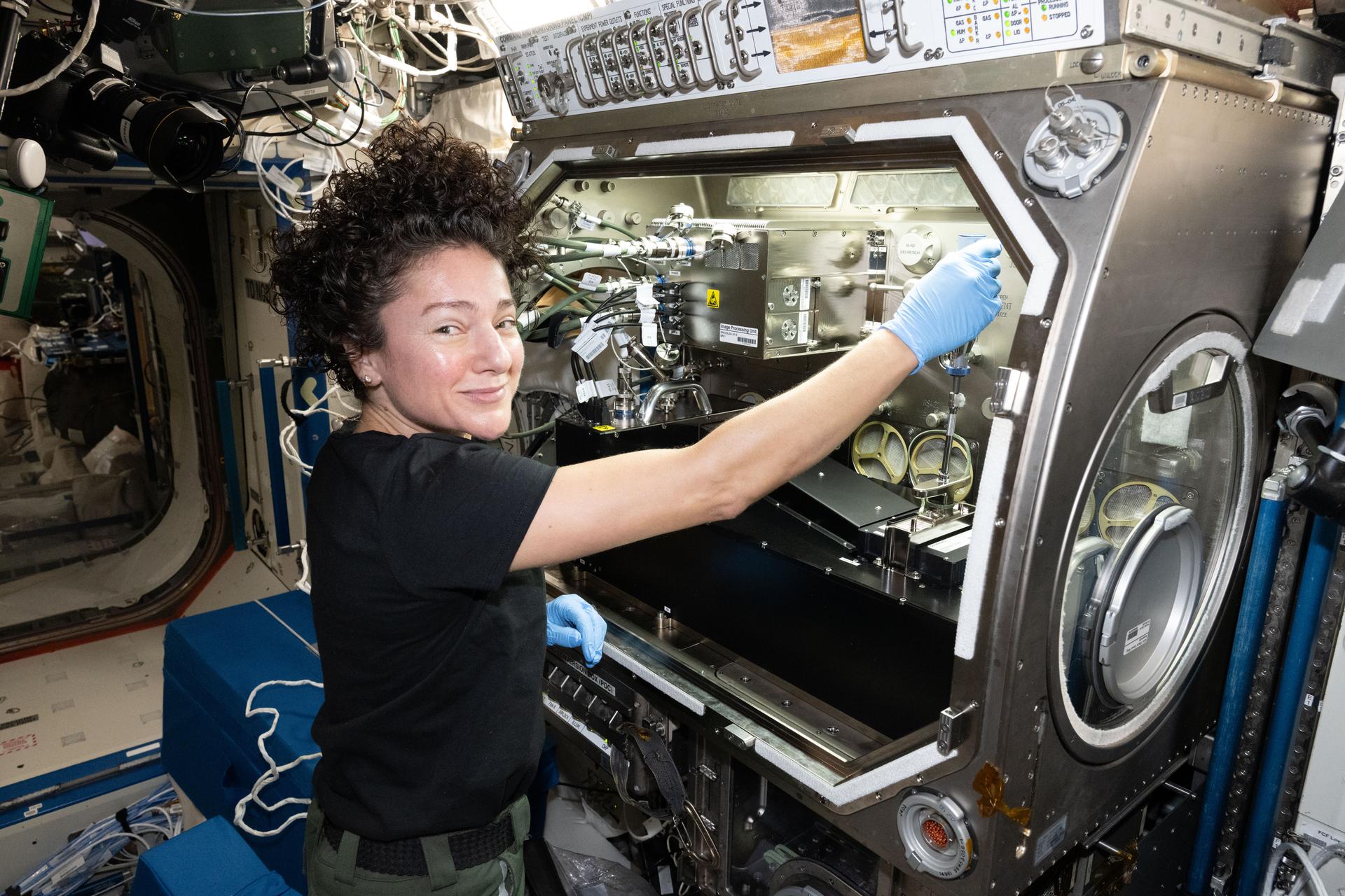
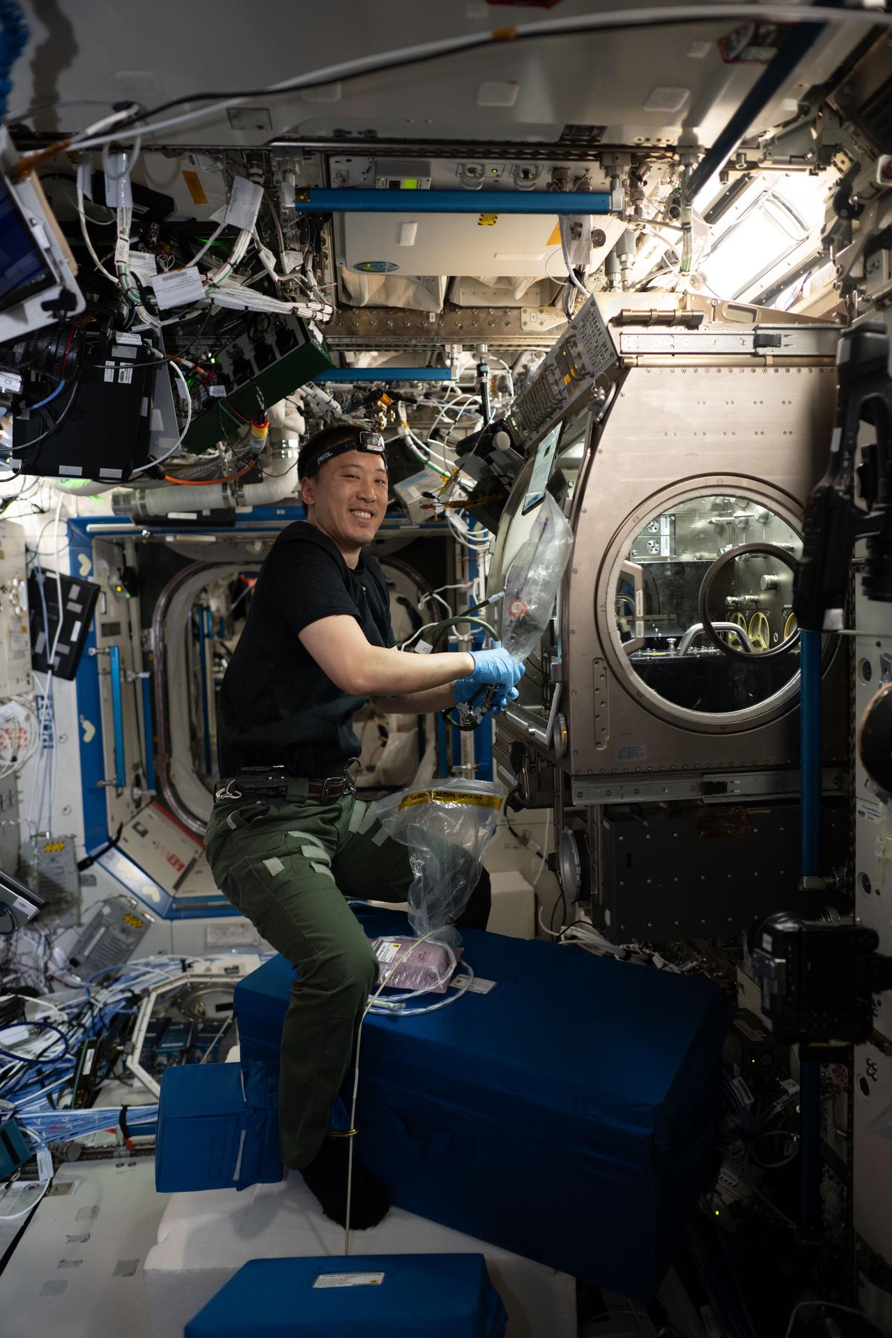
iss071e522127 (Aug. 21, 2024) --- NASA astronaut and Expedition 71 Flight Engineer Jeanette Epps configures the Metal 3D printer that manufactures experimental samples printed with stainless steel aboard the International Space Station's Columbus laboratory module. Researchers are exploring how the Metal 3D printer operates in the microgravity conditions of weightlessness and radiation as well as its ability to manufacture tools and parts on demand during space missions.
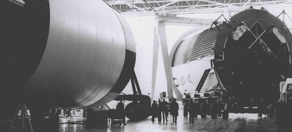
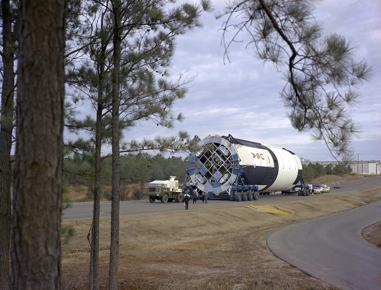
This photograph shows the Saturn V assembled LOX (Liquid Oxygen) and fuel tanks ready for transport from the Manufacturing Engineering Laboratory at Marshall Space Flight Center in Huntsville, Alabama. The tanks were then shipped to the launch site at Kennedy Space Center for a flight. The towering 363-foot Saturn V was a multi-stage, multi-engine launch vehicle standing taller than the Statue of Liberty. Altogether, the Saturn V engines produced as much power as 85 Hoover Dams.
This small group of unidentified officials is dwarfed by the gigantic size of the Saturn V first stage (S-1C) at the shipping area of the Manufacturing Engineering Laboratory at Marshall Space Flight Center in Huntsville, Alabama. The towering 363-foot Saturn V was a multi-stage, multi-engine launch vehicle standing taller than the Statue of Liberty. Altogether, the Saturn V engines produced as much power as 85 Hoover Dams.
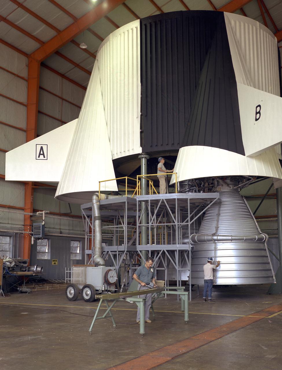
This image illustrates technicians working on a full scale engineering mock-up of a Saturn V S-IC stage thrust structure nearing completion at the Manufacturing Engineering Laboratory at Marshall Space Flight Center. The booster, 33 feet in diameter and 138 feet long, was powered by five F-1 engines that provided 7,500,000 pounds of thrust to start the monstrous vehicle on its journey into space.
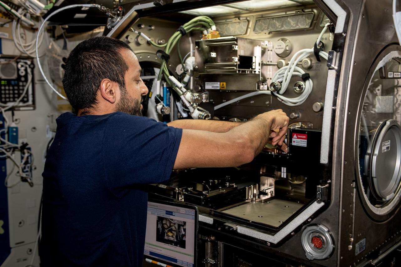
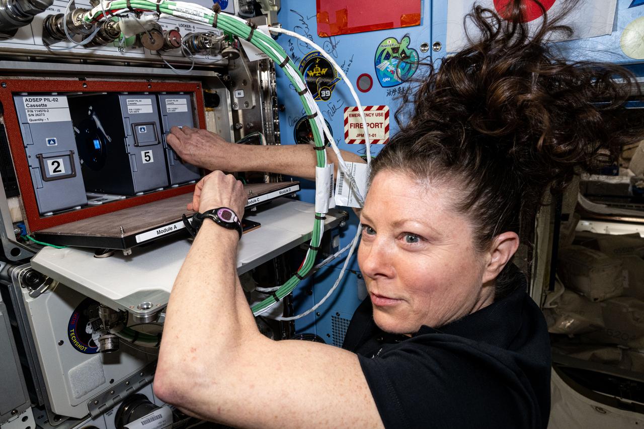
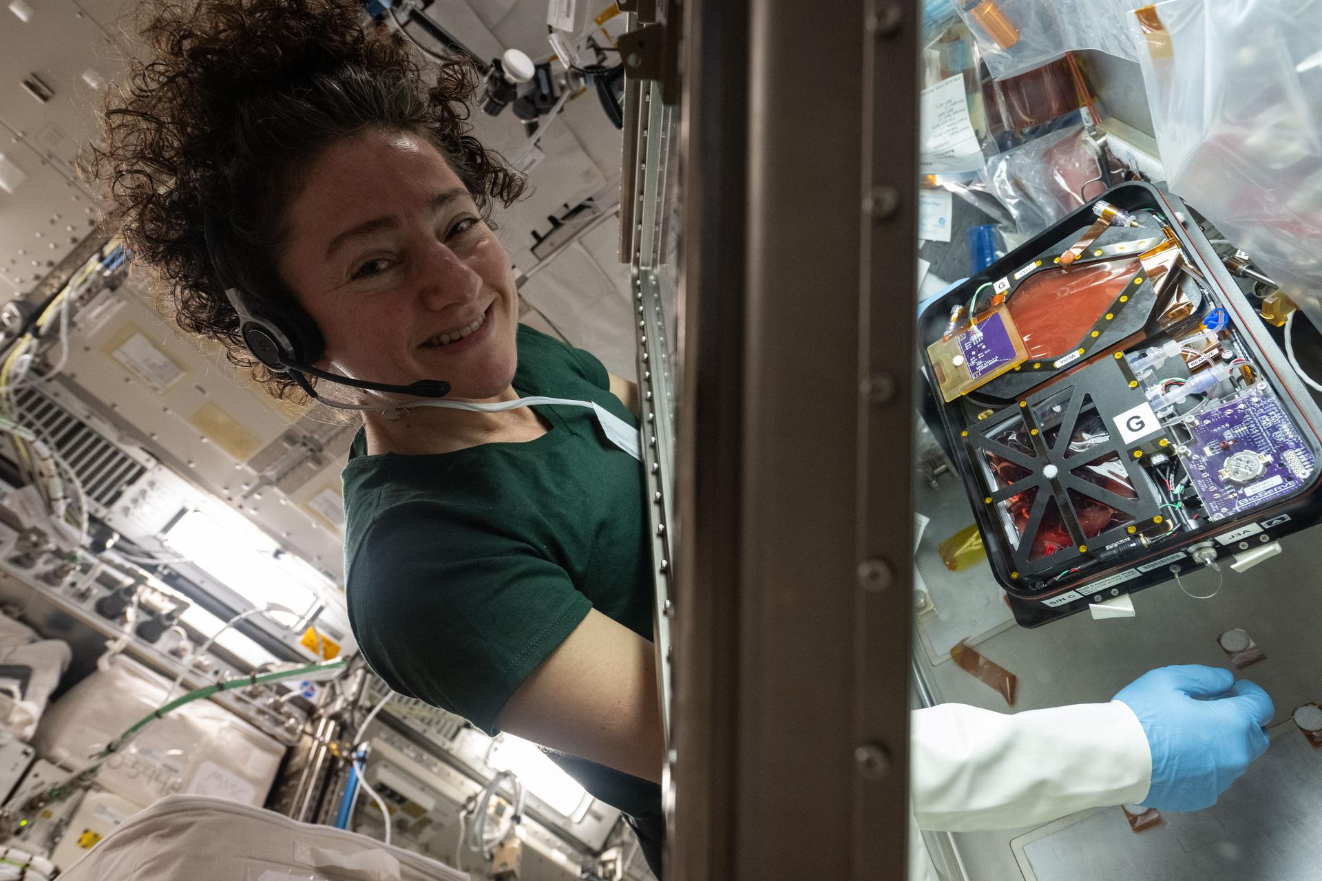
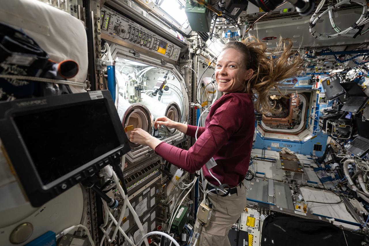
iss073e0817247 (Sept. 30, 2025) --- NASA astronaut and Expedition 73 Flight Engineer Zena Cardman installs sample cassettes into the ADSEP-4 (Advanced Space Experiment Processor) located inside the International Space Station's Destiny laboratory module. She was conducting research operations for the Pharmaceutical In-space Laboratory biotechnology experiment, which is investigating methods to advance pharmaceutical manufacturing in microgravity.
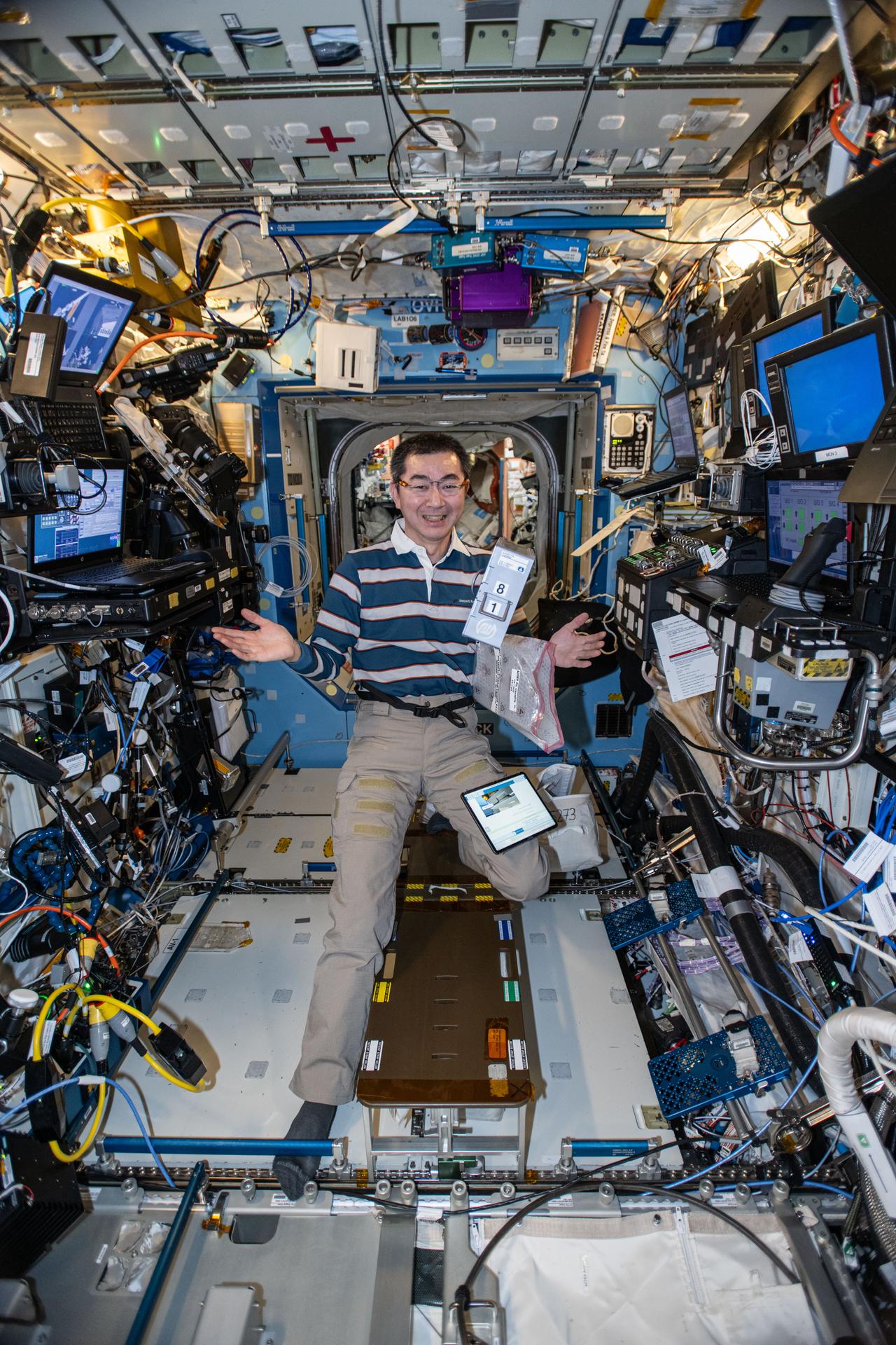
iss074e0043601 (Jan. 5, 2026) --- JAXA (Japan Aerospace Exploration Agency) astronaut and Expedition 74 Flight Engineer Kimiya Yui appears to juggle research hardware inside the International Space Station's Destiny laboratory. The science gear includes a computer tablet and a cassette designed to hold protein crystal samples, both supporting the Pharmaceutical In-Space Laboratory set of experiments that is exploring ways to develop and manufacture medicines in space.
iss071e523326 (Aug. 21, 2024) --- NASA astronauts (from left) Suni Williams, Pilot for Boeing's Crew Flight Test, and Jeanette Epps, Expedition 71 Flight Engineer, configure the Metal 3D printer inside the Columbus laboratory module. They retrieved an experimental sample printed with stainless steel, replaced a substrate in the advanced manufacturing hardware, then reinstalled the 3D printer back in Columbus' European Drawer Rack-2. Researchers are exploring how the Metal 3D printer operates in the microgravity conditions of weightlessness and radiation as well as its ability to manufacture tools and parts on demand during space missions.
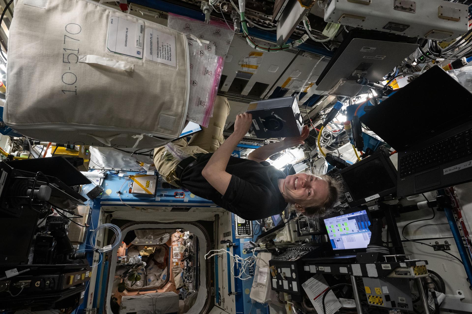
iss071e515505 (Aug. 20, 2024) --- NASA astronaut and Expedition 71 Flight Engineer Tracy C. Dyson displays a sample processor for the Pharmaceutical In-space Laboratory experiment that is exploring the production and manufacturing of medicines to benefit astronauts in space and humans on Earth. She installed the processor in the Advanced Space Experiment Processor, or ADSEP, that can house a variety of research samples and be delivered to the International Space Station and returned to Earth aboard the SpaceX Dragon cargo craft.
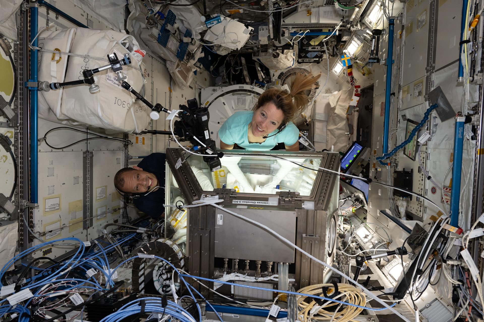
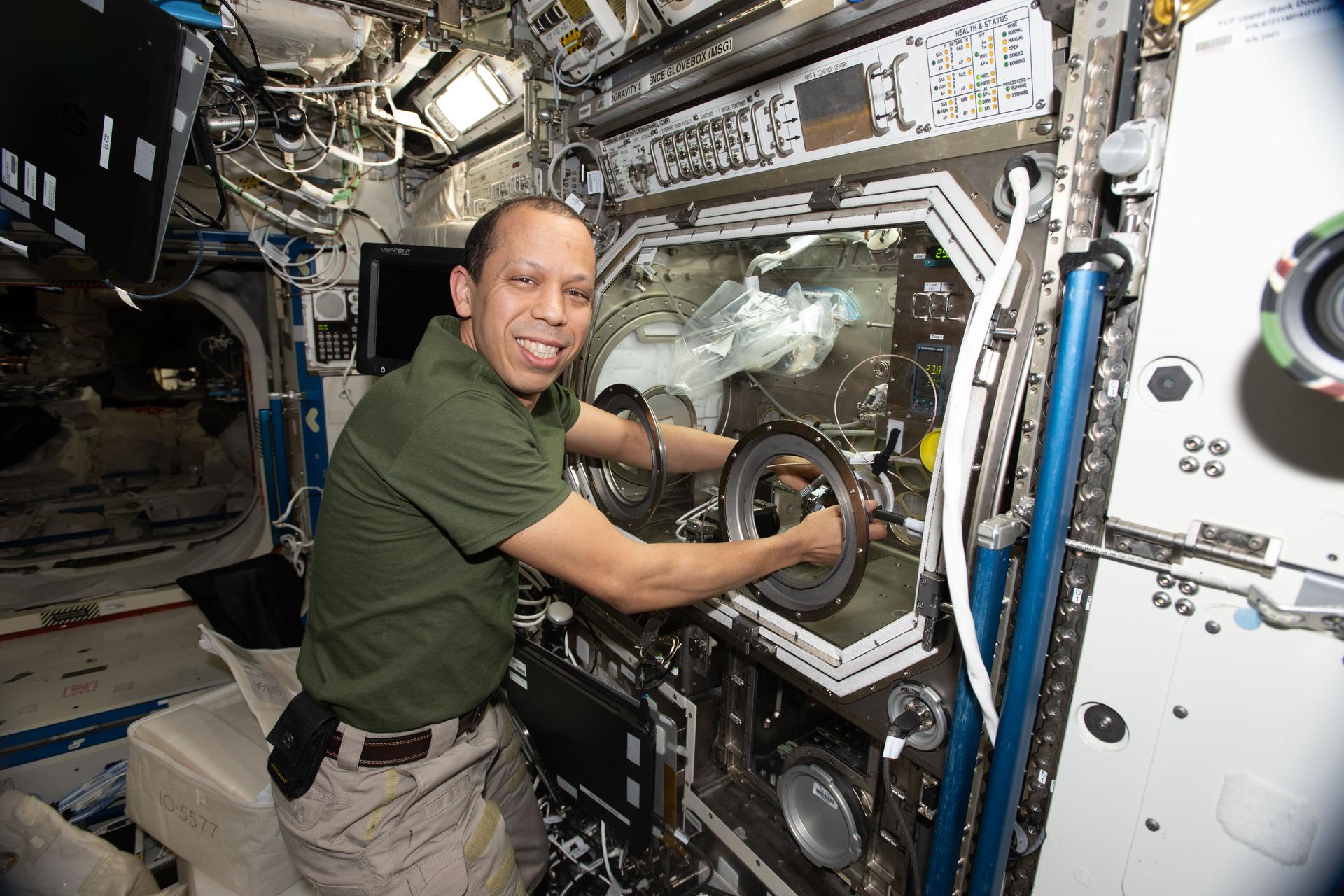
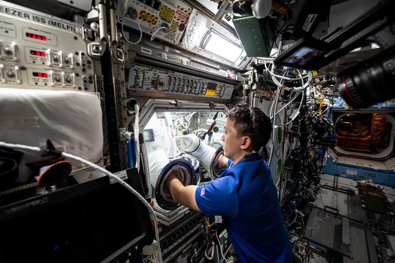
iss069e008883 (May 5, 2023) --- UAE (United Arab Emirates) astronaut and Expedition 69 Flight Engineer Sultan Alneyadi removes physics research hardware from inside the Destiny laboratory module's Microgravity Science Glovebox. The Particle Vibrations experiment investigated the self-organization mechanisms of particles in fluids potentially providing insights into new manufacturing techniques and the formation of planets and asteroids.
iss073e0253839 (July 1, 2025) --- NASA astronaut and Expedition 73 Flight Engineer Nichole Ayers removes physics research hardware from inside the Microgravity Science Glovebox located inside the International Space Station's Destiny laboratory module. Ayers was completing operations with the Ring Sheared Drop investigation that may benefit pharmaceutical manufacturing techniques and 3D printing in space.
iss068e053964 (Feb. 14, 2023) --- NASA astronaut and Expedition 68 Flight Engineer Josh Cassada uses a plastic glovebox attached to the BioFabrication Facility (BFF) and tests the research device's performance. The BFF is located in the International Space Station's Columbus laboratory module and seeks to take advantage of the microgravity environment and demonstrate the printing of organ-like tissues in space which may lead to the future manufacturing of human organs.
The Saturn V S-IC-T stage (static testing stage) was enroute from the Manufacturing Engineering Laboratory to the newly-built S-1C Static Test Stand at the Marshall Space Flight Center west test area. Known as S-IC-T, the stage was a static test vehicle not intended for flight. It was ground tested repeatedly over a period of many months proving the vehicle's propulsion system.
iss071e486706 (Aug. 15, 2024) --- NASA astronaut and Expedition 71 Flight Engineer Tracy C. Dyson swaps out sample processors for the Pharmaceutical In-space Laboratory experiment that is exploring the production and manufacturing of medicines to benefit astronauts in space and humans on Earth. The processors were installed in the Advanced Space Experiment Processor, or ADSEP, that can process a variety of research samples and be delivered to the International Space Station and returned to Earth aboard the SpaceX Dragon cargo craft.
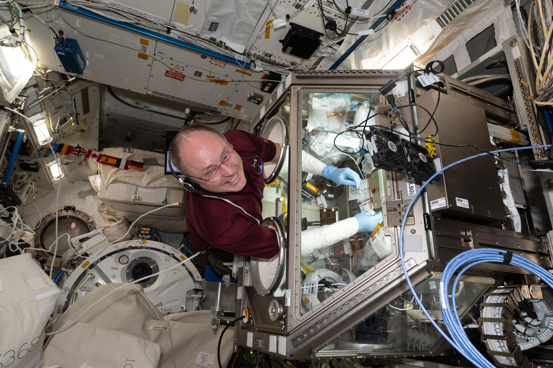
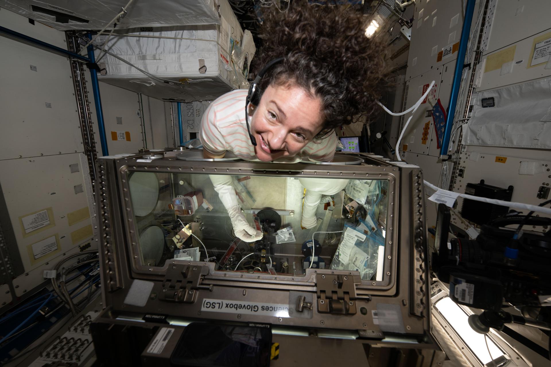
iss071e485590 (Aug. 14, 2024) --- NASA astronaut and Expedition 71 Flight Engineer Tracy C. Dyson cleans the inside of the Life Science Glovebox located aboard the International Space Station's Kibo laboratory. Dyson had earlier completed stem cell research operations exploring ways to advance cellular manufacturing and improve human health.
iss073e0253837 (July 1, 2025) --- NASA astronaut and Expedition 73 Flight Engineer Nichole Ayers poses for a portrait as she removes physics research hardware from inside the Microgravity Science Glovebox located inside the International Space Station's Destiny laboratory module. Ayers was completing operations with the Ring Sheared Drop investigation that may benefit pharmaceutical manufacturing techniques and 3D printing in space.

iss072e747124 (March 18, 2025) --- NASA astronaut and Expedition 72 Flight Engineer Nichole Ayers works inside the International Space Station's Kibo laboratory module loading software onto an Astrobee robotic free-flyer. The software is part of a technology investigation demonstrating an adaptor for docking and close approach sensing to connect both active and passive objects in space. Results may enable applications such as satellite servicing, orbital refueling, spacecraft repair and upgrade, and in-orbit manufacturing.
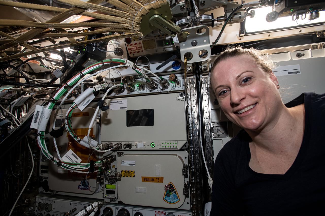
iss064e037167 (Feb. 23, 2021) --- NASA astronaut and Expedition 64 Flight Engineer Kate Rubins poses next to the TangoLab Facility that she had finished installing into an EXPRESS rack located inside the International Space Station's U.S. Destiny laboratory module. The TangoLab is a small research facility that enables a variety of microgravity science, research and development, and pilot manufacturing opportunities.
iss074e0364909 (March 6, 2026) --- NASA astronaut and Expedition 74 flight engineer Jessica Meir works inside the International Space Station’s Kibo laboratory, processing samples for the StarSteel materials research experiment. Meir investigated stainless‑steel spheres produced in Kibo’s Electrostatic Levitation Furnace to observe and understand metallic solidification behavior in microgravity, potentially benefiting Earth‑based and space‑based metallurgy and manufacturing techniques. Credit: NASA/Jessica Meir
iss074e0364965 (March 6, 2026) --- NASA astronaut and Expedition 74 flight engineer Jessica Meir works inside the International Space Station’s Kibo laboratory, configuring hardware for the StarSteel materials research experiment. Meir was preparing to investigate stainless‑steel spheres produced inside Kibo’s Electrostatic Levitation Furnace to observe and understand metallic solidification behavior in microgravity, potentially benefiting both Earth-based and space-based metallurgy and manufacturing techniques. Credit: NASA/Jessica Meir
Performance Acceptance Test of a prototype-model NEXT (NASA Evolutionary Xenon Thruster) ion engine that was delivered to NASA Glenn Research Center by Aerojet. The test dates were May 10 - May 17, 2006. The test was conducted in the Vacuum Facility 6 test facility located in the Electric Power Laboratory. The test successfully demonstrated the PM manufacturing process carried out by Aerojet under the guidance of NASA Glenn Research Center and PM1 acceptable functionality
iss073e1046752 (Oct. 31, 2025) --- NASA astronaut and Expedition 73 Flight Engineer Mike Fincke conducts research operations inside the Life Science Glovebox aboard the International Space Station’s Kibo laboratory module. Fincke was assisting scientists in studying the behavior, growth, and differentiation of stem cells, and how they can be converted into brain or heart cells in microgravity. The results could lead to advancements in crew health monitoring and drug manufacturing in space, as well as new treatments for heart and neurodegenerative diseases on Earth.
iss069e086005 (Sept. 6, 2023) --- JAXA (Japan Aerospace Exploration Agency) astronaut and Expedition 69 Flight Engineer Satoshi Furukawa replaces components on the BioFabrication Facility (BFF). The 3D biological printer, located in the International Space Station's Columbus laboratory module, is testing printing organ-like tissues in microgravity with an eye to manufacturing whole human organs in space in the future.
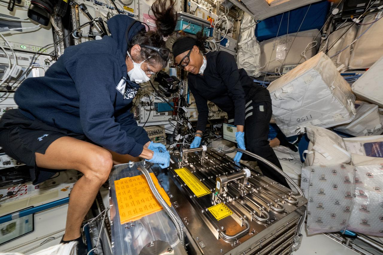
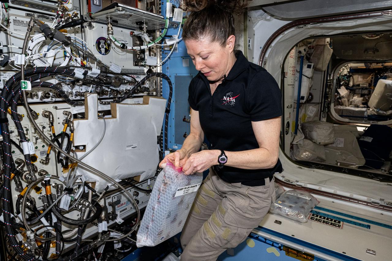
iss073e0865452 (Oct. 7, 2025) --- NASA astronaut and Expedition 73 Flight Engineer Zena Cardman inspects sample cassettes for installation into the Advanced Space Experiment Processor-4 (ADSEP-4) at the maintenance work area inside the International Space Station's Harmony module. She was conducting research operations for the Pharmaceutical In-space Laboratory biotechnology experiment, which is investigating methods to advance pharmaceutical manufacturing in microgravity.
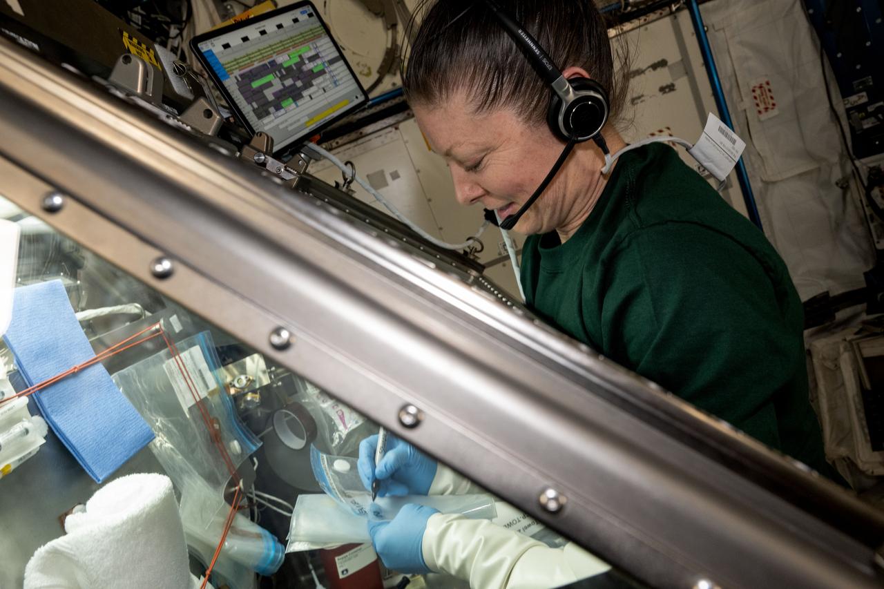
iss073e0606528 (Sept. 4, 2025) --- NASA astronaut and Expedition 73 Flight Engineer Mike Fincke sets up the Colloidal Solids research hardware inside the Destiny laboratory module’s Microgravity Science Glovebox aboard the International Space Station. The physics study is investigating pharmaceutical manufacturing and 3D printing techniques in space potentially advancing human health on and off the Earth.
iss073e0253842 (July 1, 2025) --- NASA astronaut and Expedition 73 Flight Engineer Nichole Ayers stows physics research hardware from inside the Microgravity Science Glovebox located inside the International Space Station's Destiny laboratory module. Ayers was completing operations with the Ring Sheared Drop investigation that may benefit pharmaceutical manufacturing techniques and 3D printing in space.
iss071e486657 (Aug. 15, 2024) --- NASA astronaut and Expedition 71 Flight Engineer Tracy C. Dyson swaps out sample processors for the Pharmaceutical In-space Laboratory experiment that is exploring the production and manufacturing of medicines to benefit astronauts in space and humans on Earth. The processors were installed in the Advanced Space Experiment Processor, or ADSEP, that can process a variety of research samples and be delivered to the International Space Station and returned to Earth aboard the SpaceX Dragon cargo craft.
iss073e1193970 (Nov. 25, 2025) --- NASA astronaut and Expedition 73 Flight Engineer Mike Fincke smiles for a portrait during research operations for the Droplets fluid physics investigation. Fincke was inside the International Space Station's Destiny laboratory module exploring how particles behave inside fluids. The microgravity study may inform commercial in-space manufacturing techniques and improve optical materials and pollution removal operations.
iss073e0865458 (Oct. 7, 2025) --- NASA astronaut and Expedition 73 Flight Engineer Zena Cardman inspects sample cassettes for installation into the Advanced Space Experiment Processor-4 (ADSEP-4) at the maintenance work area inside the International Space Station's Harmony module. She was conducting research operations for the Pharmaceutical In-space Laboratory biotechnology experiment, which is investigating methods to advance pharmaceutical manufacturing in microgravity.
ISS036-E-023770 (22 July 2013) --- NASA astronaut Chris Cassidy, Expedition 36 flight engineer, conducts science work with the ongoing experiment Advanced Colloids Experiment-1 (ACE-1) inside the Fluids Integrated Rack. The experiment observes colloids, microscopic particles evenly dispersed throughout materials, with the potential for manufacturing improved materials and products on Earth. Cassidy is working at the Light Microscopy Module (LMM) in the Destiny laboratory of the International Space Station.
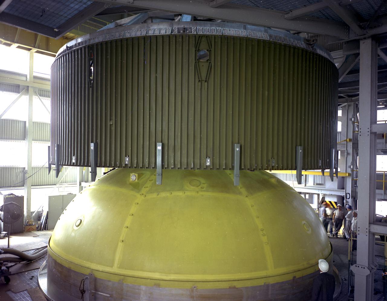
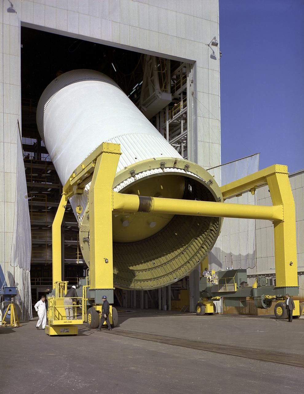
This photograph depicts a forward skirt being placed on the liquid oxygen tank for Saturn V S-IC (first) stage in the Manufacturing Engineering Laboratory at the Marshall Space Flight Center. Thirty-three feet in diameter, the fuel tanks hold a total of 4,400,000 pounds of fuel. Although this tankage was assembled at MSFC, the elements were made by the Boeing Company at Wichita and the Michoud Operations at New Orleans.
iss073e0880232 (Oct. 14, 2025) --- NASA astronaut and Expedition 73 Flight Engineer Mike Fincke smiles for a portrait during maintenance on the BioFabrication Facility inside the International Space Station's Columbus laboratory module. This advanced 3D bioprinter is designed to print organ-like tissues in microgravity, demonstrating the potential to manufacture fully functional human organs using a patient’s own cells.

iss068e045093 (Feb. 3, 2023) --- NASA astronaut and Expedition 68 Flight Engineer Frank Rubio sets up the new Particle Vibration experiment inside the Destiny laboratory module’s Microgravity Science Glovebox. The physics study will investigate how particles organize themselves in fluids possibly advancing manufacturing techniques and providing new insights on astrophysics.
iss066e156064 (March 2, 2022) --- NASA astronaut and Expediiton 66 Flight Engineer Kayla Barron sets up hardware for the Intelligent Glass Optics investigation in the International Space Station's Microgravity Science Glovebox located in the U.S. Destiny laboratory. The advanced physics study may provide insights into manufacturing systems for Earth and space including communications, aerospace, and medical diagnostics.
iss073e0880239 (Oct. 14, 2025) --- NASA astronaut and Expedition 73 Flight Engineer Mike Fincke conducts maintenance on the BioFabrication Facility inside the International Space Station's Columbus laboratory module. The advanced 3D bioprinter is designed to print organ-like tissues in microgravity, demonstrating the potential to manufacture fully functional human organs using a patient’s own cells.
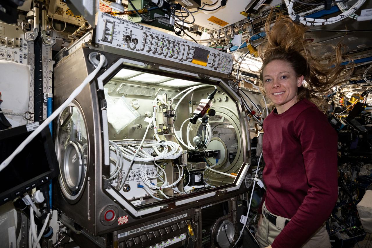
iss073e0606547 (Sept. 4, 2025) --- NASA astronaut and Expedition 73 Flight Engineer Mike Fincke poses for a portrait in front of the Microgravity Science Glovebox (MSG) inside the International Space Station’s Destiny laboratory. Fincke installed the Colloidal Solids research hardware in the MSG to explore pharmaceutical manufacturing and 3D printing techniques in microgravity—research that could advance human health both in space and on Earth.
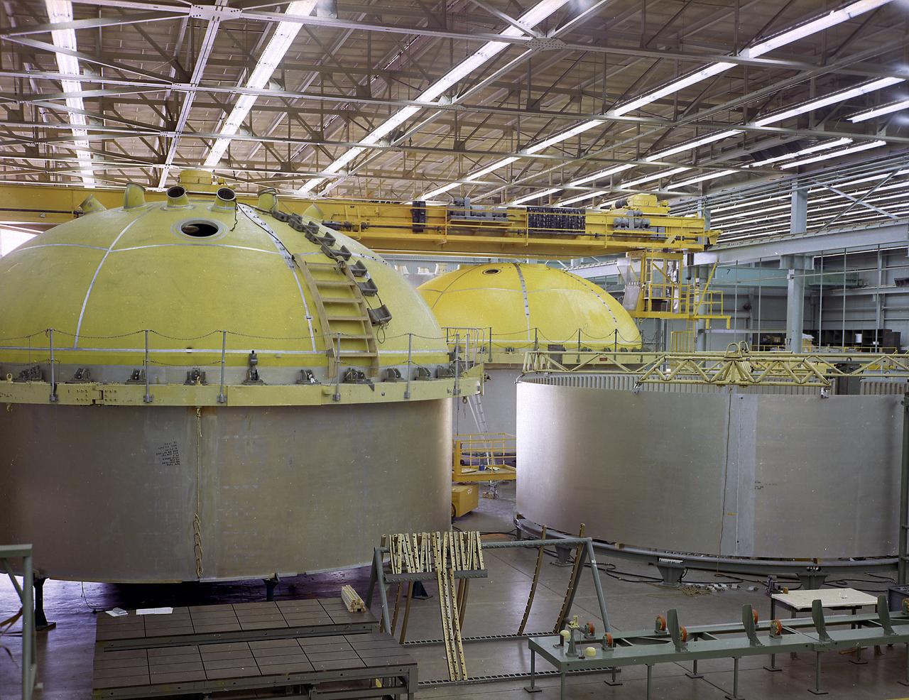
This photograph shows the components for the Saturn V S-IC stage fuel tank assembly in the Manufacturing Engineering Laboratory, building 4707, at the Marshall Space Flight Center (MSFC). Left to right are upper head, lower head, and forward skirt assembly. Thirty-three feet in diameter, they will hold a total of 4,400,000 pounds of fuel. Although this tankage was assembled at MSFC, the elements were made by the Boeing Company at Wichita and the Michould Operations at New Orleans.
iss074e0503941 (April 22, 2026) --- Expedition 74 flight engineers Chris Williams of NASA and Sophie Adenot of the European Space Agency work together in the Kibo laboratory module’s Life Science Glovebox, processing genetic-material samples for the DNA Nano Therapeutics‑3 experiment. The investigation is exploring DNA‑inspired assembly techniques as a way to manufacture treatments—such as chemotherapy and immunotherapy—that can kill cancer cells and activate the immune system. Credit: NASA/Jessica Meir
iss074e0541212 (April 29, 2026) --- NASA astronaut and Expedition 74 flight engineer Jessica Meir configures research gear inside the Destiny laboratory module's Microgravity Science Glovebox aboard the International Space Station. Meir was exploring how weightlessness affects tiny particles floating in a gelatin-like substance, known as a colloidal solid. Results may lead to advanced manufacturing techniques leading to new medicines, better food textures, and improved personal care products on Earth and in space. Credit: NASA/Jessica Meir
iss074e0604163 (May 21, 2026) --- NASA astronaut and Expedition 74 flight engineer Jessica Meir nourishes stem cell samples inside the Kibo laboratory module’s Life Science Glovebox aboard the International Space Station. The stem cell samples were incubated to help researchers learn how to manufacture space‑designed therapies to treat cancer and blood disorders. Credit: NASA/Chris Williams
iss074e0603672 (May 20, 2026) --- NASA astronaut and Expedition 74 flight engineer Jessica Meir processes stem cell samples inside the Life Science Glovebox aboard the International Space Station’s Kibo laboratory module. Meir nourished the stem cells being incubated to learn how to manufacture space-designed therapies to treat cancer and blood conditions. Credit: NASA/Jessica Meir
iss074e0603697 (May 20, 2026) --- NASA astronaut and Expedition 74 flight engineer Jessica Meir processes stem cell samples inside the Life Science Glovebox aboard the International Space Station’s Kibo laboratory module. Meir nourished the stem cells being incubated to learn how to manufacture space-designed therapies to treat cancer and blood conditions. Credit: NASA/Jessica Meir
iss074e0620142 (May 28, 2026) --- NASA astronaut and Expedition 74 Flight Engineer Chris Williams replaces sample hardware inside the Destiny laboratory module’s Microgravity Science Glovebox aboard the International Space Station to support semiconductor crystal research. Growing crystals in weightlessness may enable future large-scale semiconductor manufacturing, advancing the commercial space economy and supporting Earth-based industries. Credit: NASA/Jack Hathaway
iss074e0669779 (June 4, 2026) --- NASA astronaut and Expedition 74 flight engineer Jessica Meir works inside the Kibo laboratory module's Life Science Glovebox setting up research hardware for a blood stem cell investigation. Meir would later nourish the stem cells that are growing inside a research incubator to help doctors learn how to manufacture and commercialize space-designed therapies for a variety of blood cancers and immune diseases. Credit: NASA/Jack Hathaway
Researchers Robert Cummings, left, and Harold Gold with the small Low Cost Engine in the shadow of the much larger Quiet Engine at the National Aeronautics and Space Administration (NASA) Lewis Research Center. The two engines were being studied in different test cells at the Propulsion Systems Laboratory. Jet engines had proven themselves on military and large transport aircraft, but their use on small general aviation aircraft was precluded by cost. Lewis undertook a multiyear effort to develop a less expensive engine to fill this niche using existing technologies. Lewis researchers designed a four-stage, axial-flow engine constructed from sheet metal. It was only 11.5 inches in diameter and weighed 100 pounds. The final design specifications were turned over to a manufacturer in 1972. Four engines were created, and, as expected, the fabrication and assembly of the engine were comparatively inexpensive. In 1973 the Low Cost Engine had its first realistic analysis in the Propulsion Systems Laboratory altitude tank. The engine successfully operated at speeds up to Mach 1.24 and simulated altitudes of 30,000 feet. NASA released the engine to private industry in the hope that design elements would be incorporated into future projects and reduce the overall cost of small jet aircraft. Small jet and turboprop engines became relatively common in general aviation aircraft by the late 1970s.
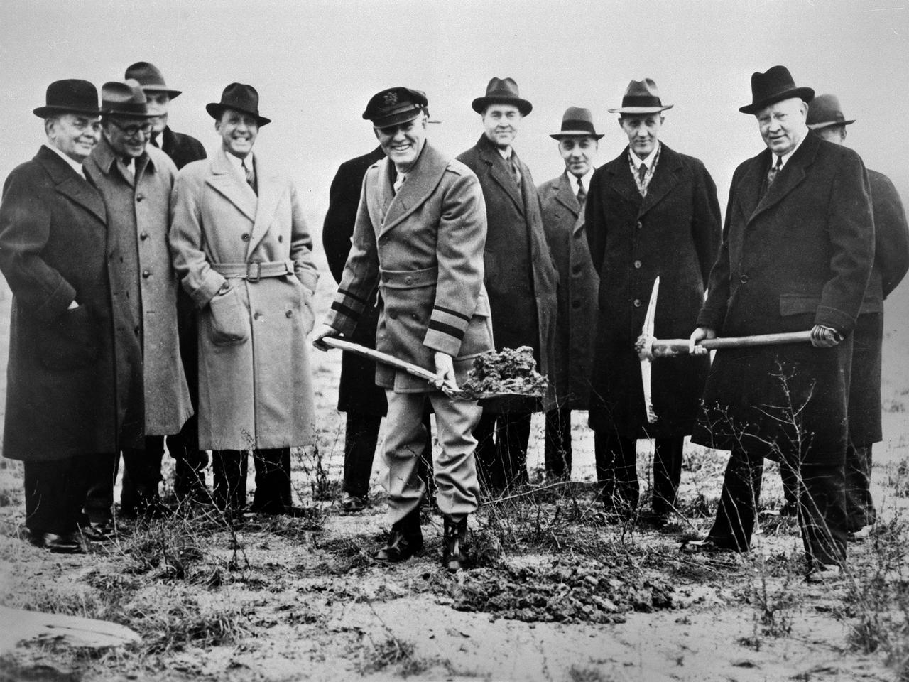
Local politicians and National Advisory Committee for Aeronautics (NACA) officials were on hand for the January 23, 1941 groundbreaking for the NACA’s Aircraft Engine Research Laboratory (AERL). The NACA was established in 1915 to coordinate the nation’s aeronautical research. The committee opened a research laboratory at Langley Field in 1920. By the late 1930s, however, European nations, Germany in particular, were building faster and higher flying aircraft. The NACA decided to expand with a new Ames Aeronautical Laboratory dedicated to high-speed flight and the AERL to handle engine-related research. The NACA examined a number of Midwest locations for its new engine lab before deciding on Cleveland. At the time, Cleveland possessed the nation’s most advanced airport, several key aircraft manufacturing companies, and was home to the National Air Races. Local officials were also able to broker a deal with the power company to discount its electricity rates if the large wind tunnels were operated overnight. The decision was made in October 1940, and the groundbreaking alongside the airport took place on January 23, 1941. From left to right: William Hopkins, John Berry, Ray Sharp, Frederick Crawford, George Brett, Edward Warner, Sydney Kraus, Edward Blythin, and George Lewis

iss073e0178587 (June 16, 2025) --- NASA astronaut and Expedition 73 Flight Engineer Nichole Ayers conducts research operations inside the Destiny laboratory module's Microgravity Science Glovebox aboard the International Space Station. Ayers swapped syringes containing protein samples and installed test cells inside the glovebox for the Ring-Sheared Drop Interfacial Bioprocessing of Pharmaceuticals investigation that explores using surface tension to contain liquids and study proteins without contacting solid walls. Results may benefit pharmaceutical manufacturing and 3D printing techniques on and off the Earth.
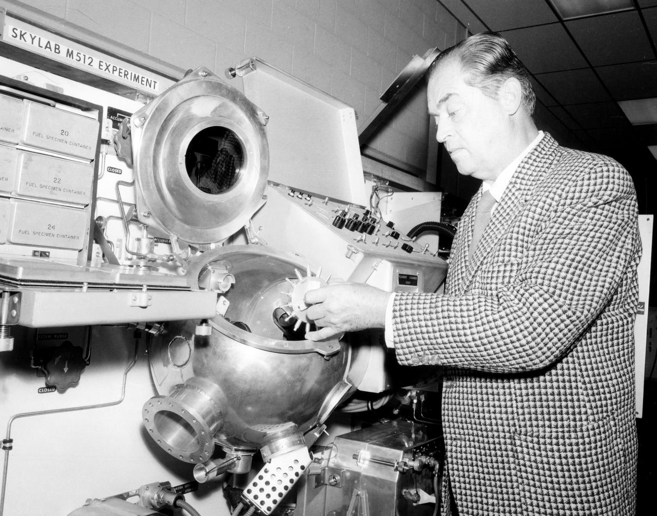
Hans F. Wuenscher, assistant director for Advanced Space Projects Engineering Laboratory at Marshall Space Flight Center (MSFC), examined the facility to be used by Skylab astronauts in performing a number of experiments in material science and manufacturing in space. The equipment shown here is a duplicate of the M512 Experiment hardware flown in the Multiple Docking Adapter section of the Sky lab. This equipment, itself an experiment, was be used for conducting 5 other experiments in the round vacuum chamber. Inside was a cavity which held the M518 Multipurpose Electric Furnace, a facility which was used for conducting other experiments. In all, a total of 17 experiments were conducted using this facility and furnace.
The components of the Saturn V booster (S-IC stage) fuel tank are shown in this photograph. The liquid oxygen tank bulkhead on the left and both halves of the fuel tank were in the Marshall Space Flight Center (MSFC) Manufacturing Engineering Laboratory, building 4707. These components were used at MSFC in structural testing to prove that they could withstand the forces to which they were subjected in flight. Each S-IC stage has two tanks, one for kerosene and one for liquid oxygen, made from such components as these. Thirty-three feet in diameter, they hold a total of 4,400,000 pounds of fuel. Although this tankage was assembled at MSFC, the elements were made by the Boeing Company at Wichita and the Michoud Operations at New Orleans.
iss073e0248499 (June 25, 2025) --- NASA astronaut and Expedition 73 Flight Engineer Nichole Ayers conducts research operations inside the Destiny laboratory module's Microgravity Science Glovebox aboard the International Space Station. Ayers swapped syringes containing protein samples and installed test cells inside the glovebox for the Ring-Sheared Drop Interfacial Bioprocessing of Pharmaceuticals investigation that explores using surface tension to contain liquids and study proteins without contacting solid walls. Results may benefit pharmaceutical manufacturing and 3D printing techniques on and off the Earth.
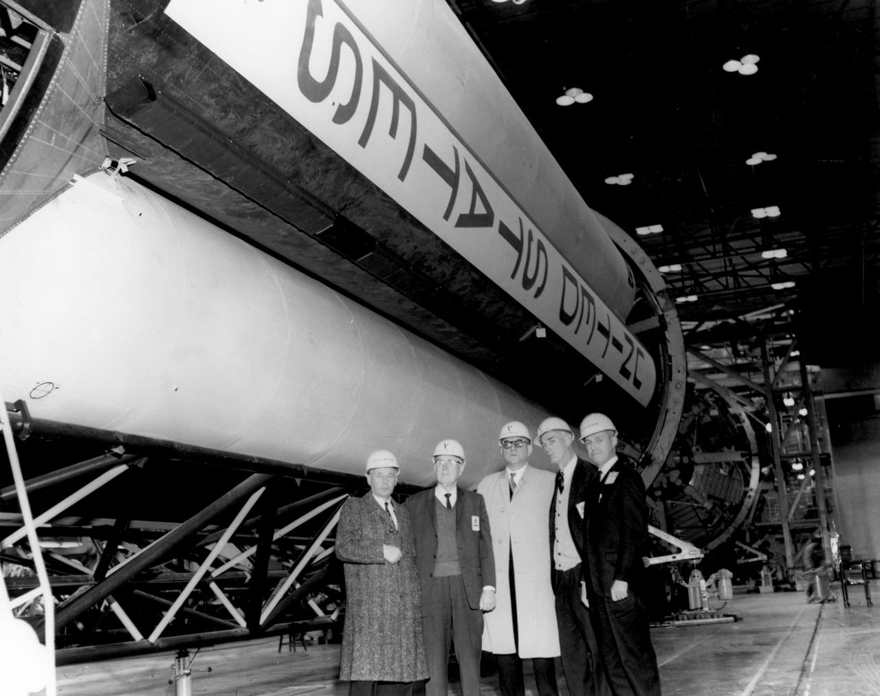
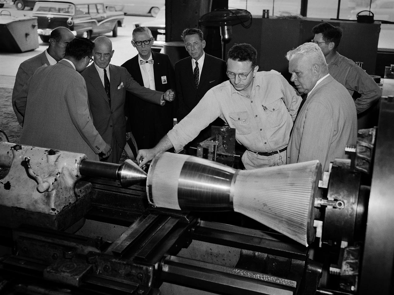
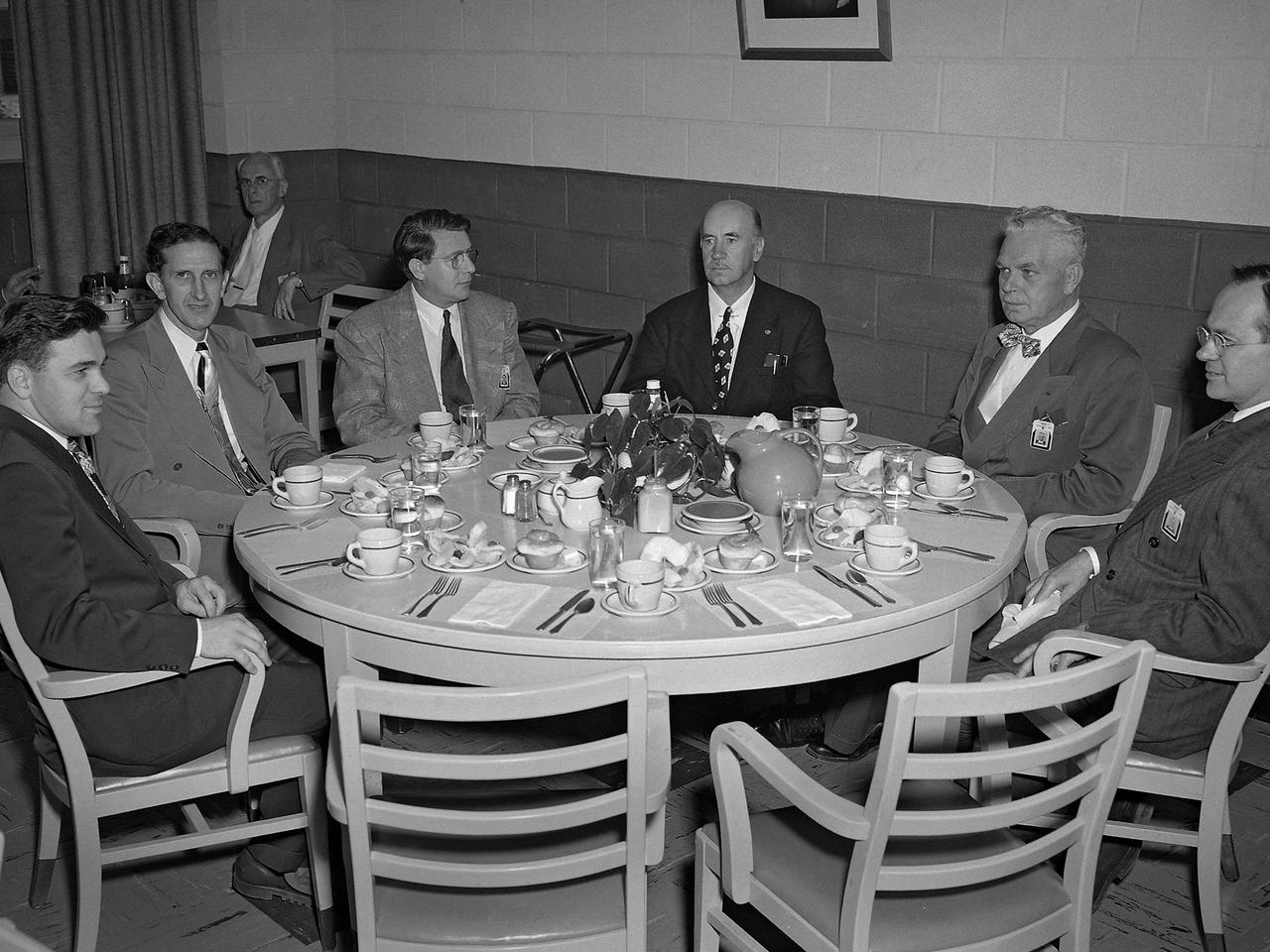
Members of the House Committee on Science and Astronautics visited the Marshall Space Flight Center (MSFC) on January 3, 1962 to gather firsthand information of the nation’s space exploration program. The congressional group was composed of members of the Subcommittee on Manned Space Flight. Shown here at MSFC’s Manufacturing Engineering Laboratory are (left to right): Dr. Eberhard Rees, MSFC; Congressman George P. Miller, Democratic representative of California; Congressman F. Edward Hebert, Democratic representative of Louisiana; Congressman Robert R. Casey, Democratic representative of Texas; and Werner Kuers, MSFC.
iss073e0886402 (Oct. 17) --- NASA astronaut and Expedition 73 Flight Engineer Jonny Kim works inside the Microgravity Science Glovebox (MSG) aboard the International Space Station’s Destiny laboratory module. Kim is seen stowing research hardware used in the Colloidal Solids physics experiment, which investigates how tiny particles—colloids—and proteins suspended in water behave in microgravity. The results may inform plant growth techniques, 3D printing technologies, and pharmaceutical manufacturing in space. On Earth, the findings could benefit the food, personal care, and healthcare industries.
iss073e0177791 (June 12, 2025) --- NASA astronaut and Expedition 73 Flight Engineer Jonny Kim conducts research operations inside the Destiny laboratory module's Microgravity Science Glovebox aboard the International Space Station. Kim swapped syringes containing protein samples and installed test cells inside the glovebox for the Ring-Sheared Drop Interfacial Bioprocessing of Pharmaceuticals investigation that explores using surface tension to contain liquids and study proteins without contacting solid walls. Results may benefit pharmaceutical manufacturing and 3D printing techniques on and off the Earth.
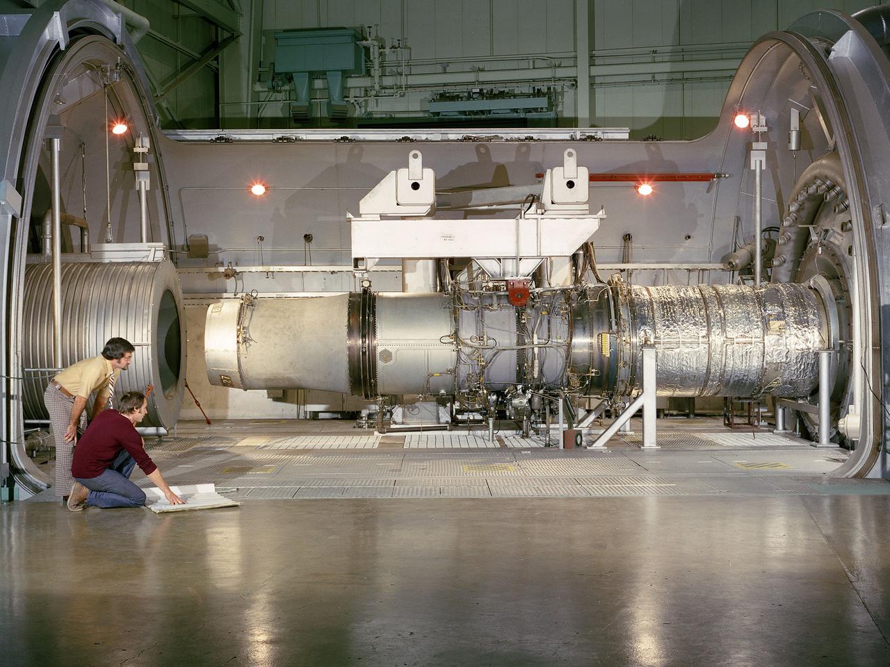
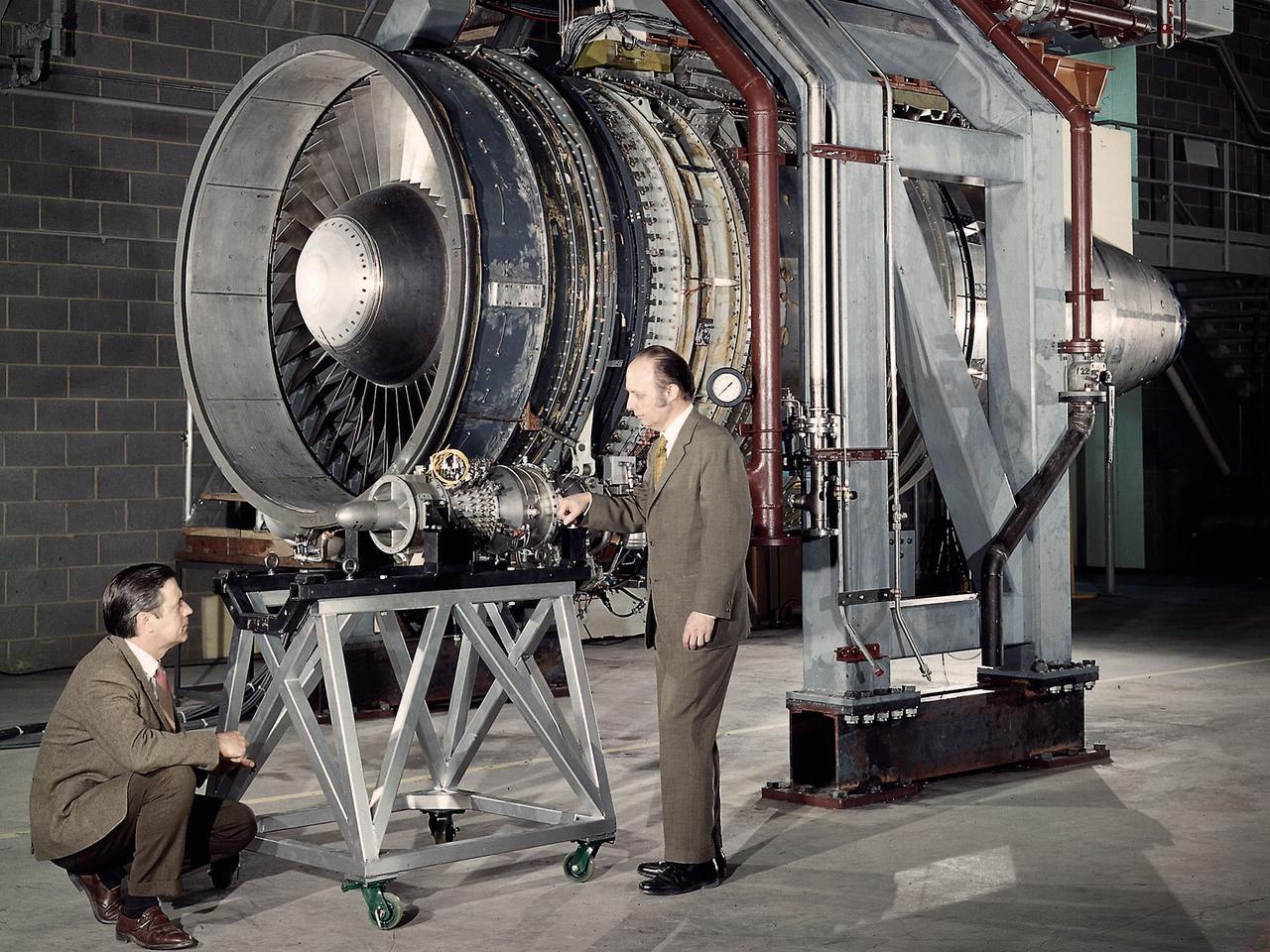
A refanned Pratt and Whitney JT-8D-109 turbofan engine installed in Cell 4 of the Propulsion Systems Laboratory at the National Aeronautics and Space Administration (NASA) Lewis Research Center. NASA Lewis’ Refan Program sought to demonstrate that noise reduction modifications could be applied to existing aircraft engines with minimal costs and without diminishing the engine’s performance or integrity. At the time, Pratt and Whitney’s JT-8D turbofans were one of the most widely used engines in the commercial airline industry. The engines powered Boeing’s 727 and 737 and McDonnell Douglas’ DC-9 aircraft. Pratt and Whitney worked with the airline manufacturers on a preliminary study that verified feasibility of replacing the JT-8D’s two-stage fan with a larger single-stage fan. The new fan slowed the engine’s exhaust, which significantly reduced the amount of noise it generated. Booster stages were added to maintain the proper level of airflow through the engine. Pratt and Whitney produced six of the modified engines, designated JT-8D-109, and performed the initial testing. One of the JT-8D-109 engines, seen here, was tested in simulated altitude conditions in NASA Lewis’ Propulsion Systems Laboratory. The Refan engine was ground-tested on an actual aircraft before making a series of flight tests on 727 and DC-9 aircraft in early 1976. The Refan Program reduced the JT-8D’s noise by 50 percent while increasing the fuel efficiency. The retro-fit kits were estimated to cost between $1 million and $1.7 million per aircraft.
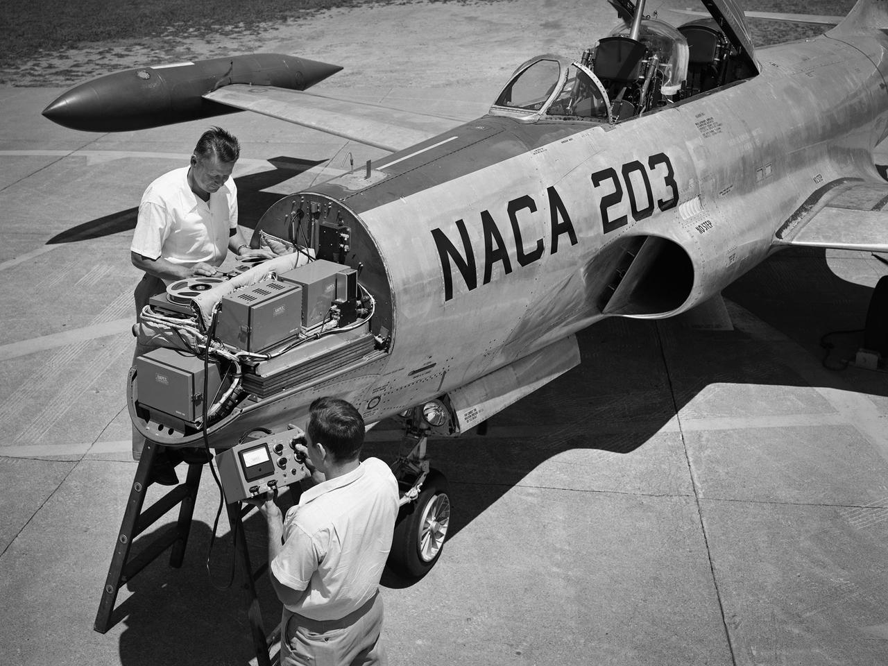
A Lockheed F-94B Starfire being equipped with an audio recording machine and sensors at the National Advisory Committee for Aeronautics (NACA) Lewis Flight Propulsion Laboratory. The NACA was investigating the acoustic effects caused by the engine’s nozzle and the air flowing along the fuselage. Airline manufacturers would soon be introducing jet engines on their passenger aircraft, and there was concern regarding the noise levels for both the passengers and public on the ground. NACA Lewis conducted a variety of noise reduction studies in its wind tunnels, laboratories, and on a F2H-2B Banshee aircraft. The F2H-2B Banshee’s initial test flights in 1955 and 1956 measured the noise emanating directly from airflow over the aircraft’s surfaces, particularly the wings. This problem was particularly pronounced at high subsonic speeds. The researchers found the majority of the noise occurred in the low and middle octaves. These investigations were enhanced with a series of flights using the F-94B Starfire. The missions measured wall-pressure, turbulence fluctuations, and mean velocity profiles. Mach 0.3 to 0.8 flights were flown at altitudes of 10,000, 20,000, and 30,000 feet with microphones mounted near the forward fuselage and on a wing. The results substantiated the wind tunnel findings. This photograph shows the tape recorder being installed in the F-94B’s nose.
A flight engineer at the National Advisory Committee for Aeronautics (NACA) Aircraft Engine Research Laboratory monitors test equipment in the rear of the Lockheed RA–29 Hudson. Lockheed manufactured several variations of the light bomber in the late 1930s. The Hudson was one of the few military aircraft models available in large quantities during the early years of World War II, and both the US and British air forces utilized it as a patrol aircraft. The RA–29s were soon superseded by newer aircraft, but continued to serve as crew trainers, light cargo carriers and staff transports. The NACA flight engineers in the Planning and Analysis Section were responsible for working with researchers to install and monitor the experimental equipment on the NACA’s research aircraft. This process could require weeks or months. When larger aircraft, like the RA–29 Hudson, were utilized the flight engineers often participated in the flights. The NACA acquired their RA–29 in November 1943, and used the aircraft for fuel blend studies and instrumentation development. The Hudson also frequently served as a transportation vehicle for the staff and visitors. The RA–29 was transferred from the NACA in July 1945.
Researcher John Sloop briefs visitors on his latest rocket engine research during the 1947 Inspection at the National Advisory Committee for Aeronautics (NACA) Lewis Flight Propulsion Laboratory. The NACA had been hosting annual Aircraft Engineering Conferences, better known as Inspections, since 1926. Individuals from the manufacturing industry, military, and university settings were invited to tour the NACA laboratories. There were a series of stops on the tour, mostly at test facilities, where researchers would brief the group on the latest efforts in their particular field. The Inspections grew in size and scope over the years and by the mid-1940s required multiple days. The three-day 1947 Inspection was the first time the event was held at NACA Lewis. Over 800 scientists, industrialists, and military leaders attended the three-day event. Talks were given at the Altitude Wind Tunnel, Four Burner Area, Engine Research Building, and other facilities. An array of topics were discussed, including full-scale engine testing, ramjets, axial-flow compressors, turbojets, fuels, icing, and materials. The NACA Lewis staff and their families were able to view the same presentations after the Inspection was over. Sloop, a researcher in the Fuels and Thermodynamics Division, briefed visitors on NACA Lewis’ early research in rocket engine propellants, combustion, and cooling. This early NACA Lewis work led to the development of liquid hydrogen as a viable propellant in the late 1950s.
New wooden fan blades being prepared for installation in the Altitude Wind Tunnel at the National Advisory Committee for Aeronautics (NACA) Lewis Flight Propulsion Laboratory. The facility underwent a major upgrade in 1951 to increase its operating capacities in order to handle the new, more powerful turbojet engines being manufactured in the 1950s. The fan blades were prepared in the shop area, seen in this photograph, before being lowered through a hole in the tunnel and attached to the drive shaft. A new drive bearing and tail faring were also installed on the fan as part of this rehab project. A 12-bladed 31-foot-diameter spruce wood fan generated the 300 to 500 mile-per-hour airflow through the tunnel. An 18,000-horsepower General Electric induction motor located in the rear corner of the Exhauster Building drove the fan at 410 revolutions per minute. An extension shaft, sealed in the tunnel’s shell with flexible couplings that allowed for the movement of the shell, connected the motor to the fan. A bronze screen secured to the turning vanes protected the fan against damage from any engine parts sailing through the tunnel. Despite this screen the blades did become worn or cracked over time and had to be replaced.
National Advisory Committee for Aeronautics (NACA) Chairman James Doolittle and Thompson Products Chairman of the Board Frederick Crawford receive a tour of the Lewis Flight Propulsion Laboratory during the last few months of the NACA. Lewis mechanic Leonard Tesar demonstrates the machining of a 20,000-pound thrust rocket engine for the group in the Fabrication Shop. From left to right, Associate Director Eugene Manganiello, researcher Edward Baehr, Doolittle, NACA Executive Secretary John Victory, Crawford, Tesar, Lewis Director Raymond Sharp, and mechanic Curtis Strawn. Doolittle began his career as a test pilot and air racer. In 1942 he famously flew a B-25 Mitchell on a daring raid over Tokyo. Doolittle also worked with the aviation industry on the development of aircraft fuels and instrumentation. After the war he served as vice president of Shell Oil and as a key government advisor. In this capacity he also served on the NACA’s Executive Committee for a number of years and served as its Chairman in 1957 and 1958. Tesar was a supervisor at the Sheet Metal Shop in the Fabrication Building. He joined the laboratory in 1948 and enrolled in their Apprentice Program. He graduated from the school three years later as an aviation metalsmith. The Fabrication Branch created a wide variety of hardware for the laboratory’s research projects. Requests from research divisions ranged from sheetmetal manufacturing for aircraft to fabrication of rocket engines. Tesar retired in 1982 after 37 years of service.
Dr. Igor Sikorsky, fourth from the left, visits the National Advisory Committee for Aeronautics (NACA) Lewis Flight Propulsion Laboratory in Cleveland, Ohio. The legendary Russian-born aviation pioneer visited NACA Lewis several times during the 1940s and 1950s. In 1946 Sikorsky arrived at Lewis for the 1946 National Air Races, which included demonstrations by five of his helicopters. NACA flight mechanic Joseph Sikosky personally escorted Sikorsky during the visit. Sikorsky frequently addressed local professional organizations, such as the American Society of Mechanical Engineers, during his visits. Sikorsky built and flew the first multi-engine aircraft as a youth in Russia. In his mid-20s Sikorsky designed and oversaw the manufacturing of 75 four-engine bombers. During the Bolshevik Revolution he fled to New York City where he worked jobs outside of aviation. In 1923 Sikorsky obtained funding to build a twin-engine water aircraft. This aircraft was the first US twin-engine flying machine and a world-wide success. In 1939 Sikorsky designed the first successful US helicopter. He then put all of his efforts into helicopters, and built some of the most successful helicopters in use today. Sikorsky passed away in 1972. From left to right: unknown; John Collins, Chief of the Engine Performance and Materials Division; Abe Silverstein, Chief of Research; Sikorsky; lab Director Ray Sharp; and Executive Officer Robert Sessions.
A 3670-horsepower Armstrong-Siddeley Python turboprop being prepared for tests in the Altitude Wind Tunnel at the National Advisory Committee for Aeronautics (NACA) Lewis Flight Propulsion Laboratory. In 1947 Lewis researcher Walter Olsen led a group of representatives from the military, industry, and the NACA on a fact finding mission to investigate the technological progress of British turbojet manufacturers. Afterwards several British engines, including the Python, were brought to Cleveland for testing in Lewis’s altitude facilities. The Python was a 14-stage axial-flow compressor turboprop with a fixed-area nozzle and contra-rotating propellers. Early turboprops combined the turbojet and piston engine technologies. They could move large quantities of air so required less engine speed and thus less fuel. This was very appealing to the military for some applications. The military asked the NACA to compare the Python’s performance at sea to that at high altitudes. The NACA researchers studied the Python in the Altitude Wind Tunnel from July 1949 through January 1950. It was the first time the tunnel was used to study an engine with the sole purpose of learning about, not improving it. They analyzed the engine’s dynamic response using a frequency response method at altitudes between 10,000 to 30,000 feet. Lewis researchers found that they could predict the dynamic response characteristics at any altitude from the data obtained from any other specific altitude. This portion of the testing was completed during a single test run.
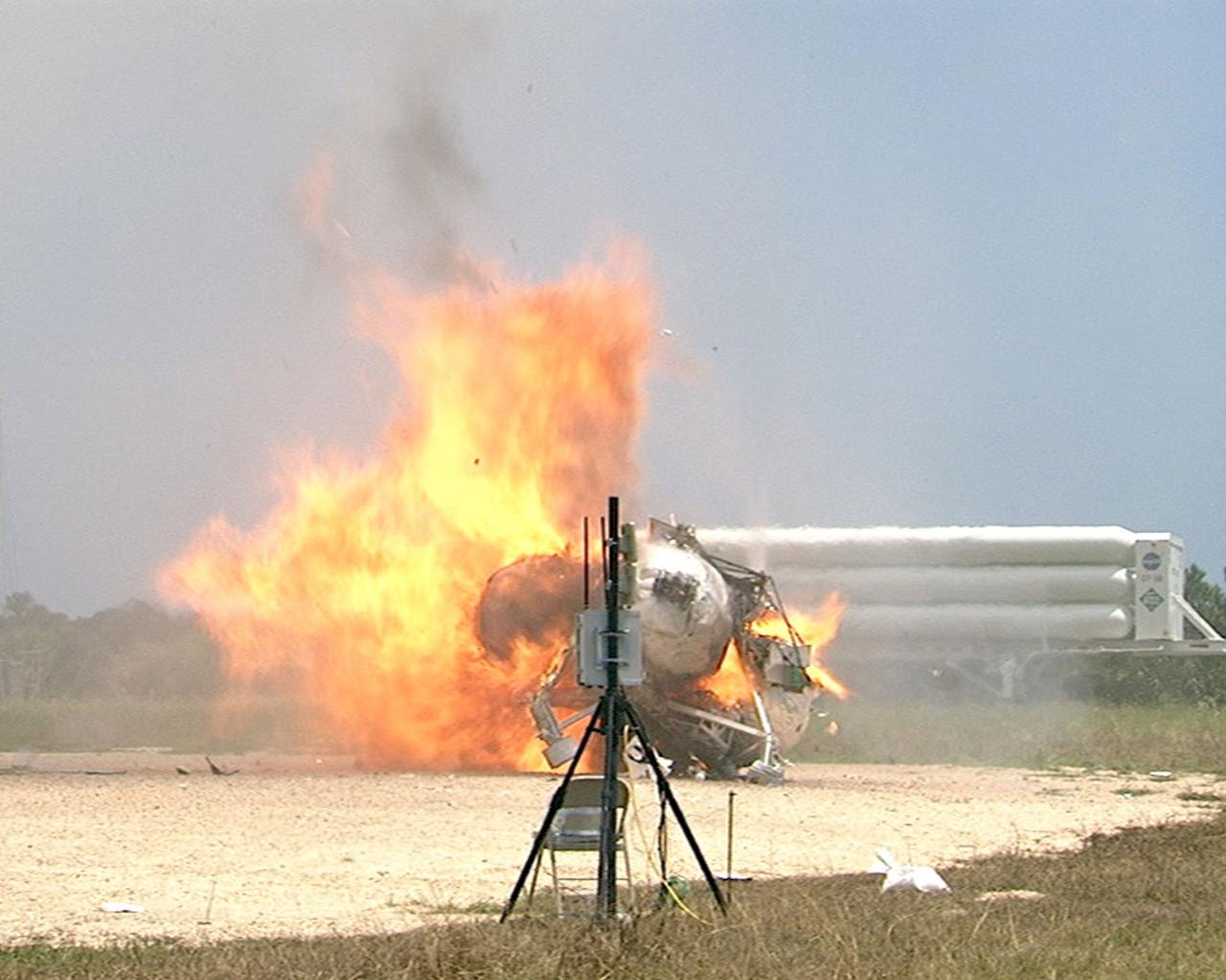
CAPE CANAVERAL, Fla. – During a free-flight test of the Project Morpheus vehicle at the Shuttle Landing Facility at NASA’s Kennedy Space Center in Florida, the vehicle lifted off the ground and then experienced a hardware component failure, which prevented it from maintaining stable flight. Engineers are looking into the test data and the agency will release information as it becomes available. Failures such as these were anticipated prior to the test, and are part of the development process for any complex spaceflight hardware. Testing of the prototype lander had been ongoing at NASA’s Johnson Space Center in Houston in preparation for its first free-flight test at Kennedy Space Center. Morpheus was manufactured and assembled at JSC and Armadillo Aerospace. Morpheus is large enough to carry 1,100 pounds of cargo to the moon – for example, a humanoid robot, a small rover, or a small laboratory to convert moon dust into oxygen. The primary focus of the test is to demonstrate an integrated propulsion and guidance, navigation and control system that can fly a lunar descent profile to exercise the Autonomous Landing and Hazard Avoidance Technology, or ALHAT, safe landing sensors and closed-loop flight control. For more information on Project Morpheus, visit http://morpheuslander.jsc.nasa.gov/. Photo credit: NASA
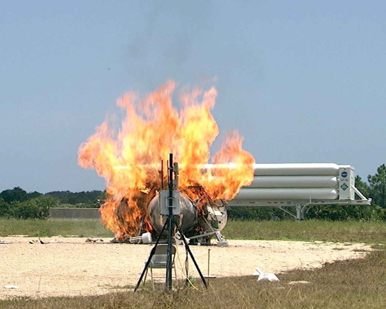
CAPE CANAVERAL, Fla. – During a free-flight test of the Project Morpheus vehicle at the Shuttle Landing Facility at NASA’s Kennedy Space Center in Florida, the vehicle lifted off the ground and then experienced a hardware component failure, which prevented it from maintaining stable flight. No one was injured and the resulting fire was extinguished by Kennedy fire personnel. Engineers are looking into the test data and the agency will release information as it becomes available. Failures such as these were anticipated prior to the test, and are part of the development process for any complex spaceflight hardware. Testing of the prototype lander had been ongoing at NASA’s Johnson Space Center in Houston in preparation for its first free-flight test at Kennedy Space Center. Morpheus was manufactured and assembled at JSC and Armadillo Aerospace. Morpheus is large enough to carry 1,100 pounds of cargo to the moon – for example, a humanoid robot, a small rover, or a small laboratory to convert moon dust into oxygen. The primary focus of the test is to demonstrate an integrated propulsion and guidance, navigation and control system that can fly a lunar descent profile to exercise the Autonomous Landing and Hazard Avoidance Technology, or ALHAT, safe landing sensors and closed-loop flight control. For more information on Project Morpheus, visit http://morpheuslander.jsc.nasa.gov/. Photo credit: NASA
After the end of the Apollo missions, NASA's next adventure into space was the marned spaceflight of Skylab. Using an S-IVB stage of the Saturn V launch vehicle, Skylab was a two-story orbiting laboratory, one floor being living quarters and the other a work room. The objectives of Skylab were to enrich our scientific knowledge of the Earth, the Sun, the stars, and cosmic space; to study the effects of weightlessness on living organisms, including man; to study the effects of the processing and manufacturing of materials utilizing the absence of gravity; and to conduct Earth resource observations. At the Marshall Space Flight Center (MSFC), astronauts and engineers spent hundreds of hours in an MSFC Neutral Buoyancy Simulator (NBS) rehearsing procedures to be used during the Skylab mission, developing techniques, and detecting and correcting potential problems. The NBS was a 40-foot deep water tank that simulated the weightlessness environment of space. This photograph shows astronaut Ed Gibbon (a prime crew member of the Skylab-4 mission) during the neutral buoyancy Skylab extravehicular activity training at the Apollo Telescope Mount (ATM) mockup. One of Skylab's major components, the ATM was the most powerful astronomical observatory ever put into orbit to date.
CAPE CANAVERAL, Fla. – During a free-flight test of the Project Morpheus vehicle at the Shuttle Landing Facility at NASA’s Kennedy Space Center in Florida, the vehicle lifted off the ground and then experienced a hardware component failure, which prevented it from maintaining stable flight. No one was injured and the resulting fire was extinguished by Kennedy fire personnel. Engineers are looking into the test data and the agency will release information as it becomes available. Failures such as these were anticipated prior to the test, and are part of the development process for any complex spaceflight hardware. Testing of the prototype lander had been ongoing at NASA’s Johnson Space Center in Houston in preparation for its first free-flight test at Kennedy Space Center. Morpheus was manufactured and assembled at JSC and Armadillo Aerospace. Morpheus is large enough to carry 1,100 pounds of cargo to the moon – for example, a humanoid robot, a small rover, or a small laboratory to convert moon dust into oxygen. The primary focus of the test is to demonstrate an integrated propulsion and guidance, navigation and control system that can fly a lunar descent profile to exercise the Autonomous Landing and Hazard Avoidance Technology, or ALHAT, safe landing sensors and closed-loop flight control. For more information on Project Morpheus, visit http://morpheuslander.jsc.nasa.gov/. Photo credit: NASA
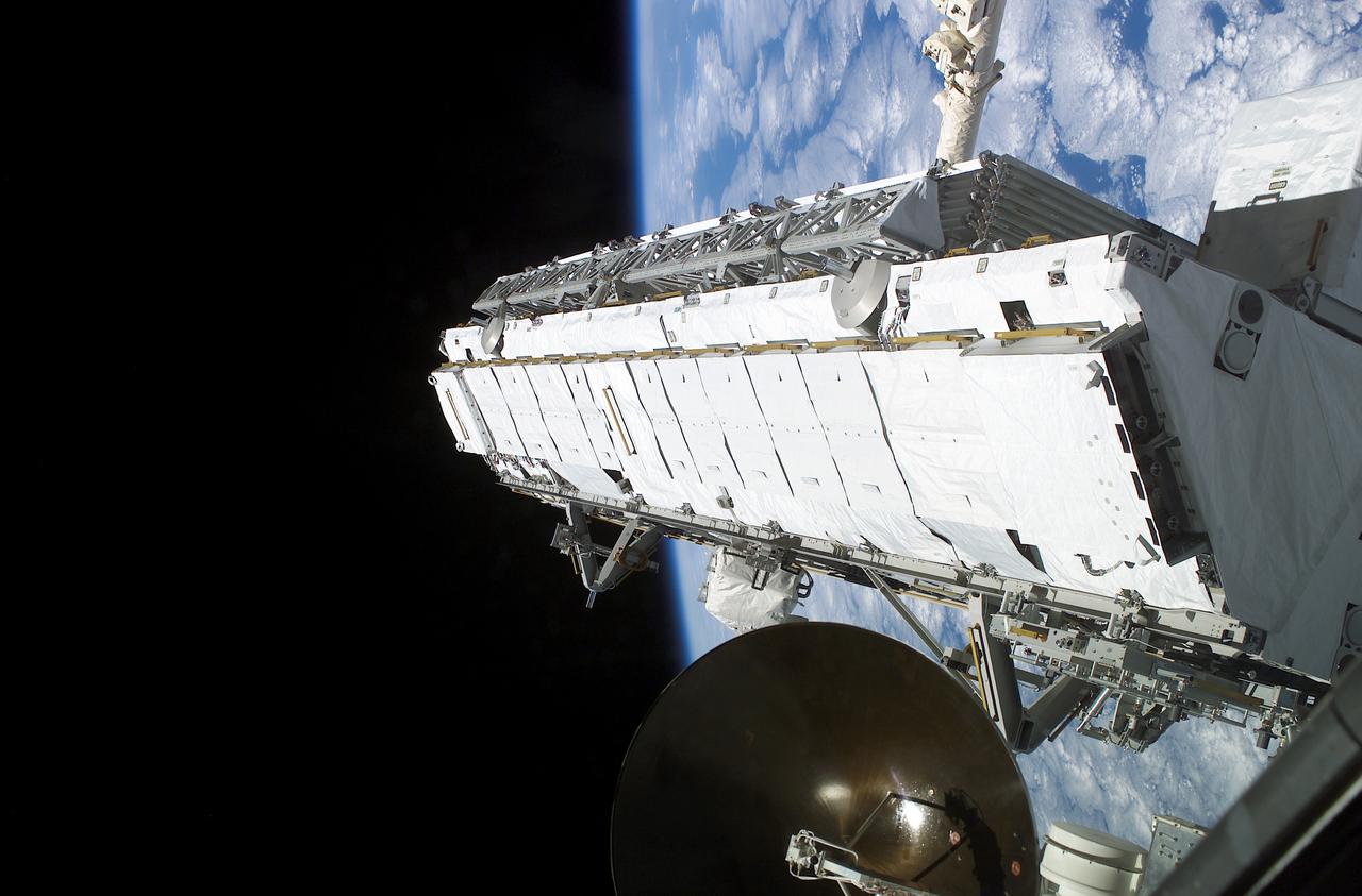
Being attached to the Canadarm2 on the International Space Station (ISS), the Remote Manipulator System arm built by the Canadian Space Agency, the Integrated Truss Assembly (S1) Truss is suspended over the Space Shuttle Orbiter Atlantis' cargo bay. Astronauts Sandra H. Magnus, STS-112 mission specialist, and Peggy A. Whitson, Expedition Five flight engineer, used the Canadarm2 from inside the Destiny laboratory on the ISS to lift the S1 truss out of the orbiter's cargo bay and move it into position prior to its installation on the ISS. The primary payloads of this mission, ISS Assembly Mission 9A, were the Integrated Truss Assembly S1 (S One), the starboard side thermal radiator truss, and the Crew Equipment Translation Aid (CETA) cart to the ISS. The S1 truss provides structural support for the orbiting research facility's radiator panels, which use ammonia to cool the Station's complex power system. The S1 truss was attached to the S0 (S Zero) truss, which was launched on April 8, 2002 aboard the STS-110, and flows 637 pounds of anhydrous ammonia through three heat-rejection radiators. The truss is 45-feet long, 15-feet wide, 10-feet tall, and weighs approximately 32,000 pounds. The CETA cart was attached to the Mobil Transporter and will be used by assembly crews on later missions. Manufactured by the Boeing Company in Huntington Beach, California, the truss primary structure was transferred to the Marshall Space Flight Center in February 1999 for hardware installations and manufacturing acceptance testing. The launch of the STS-112 mission occurred on October 7, 2002, and its 11-day mission ended on October 18, 2002.
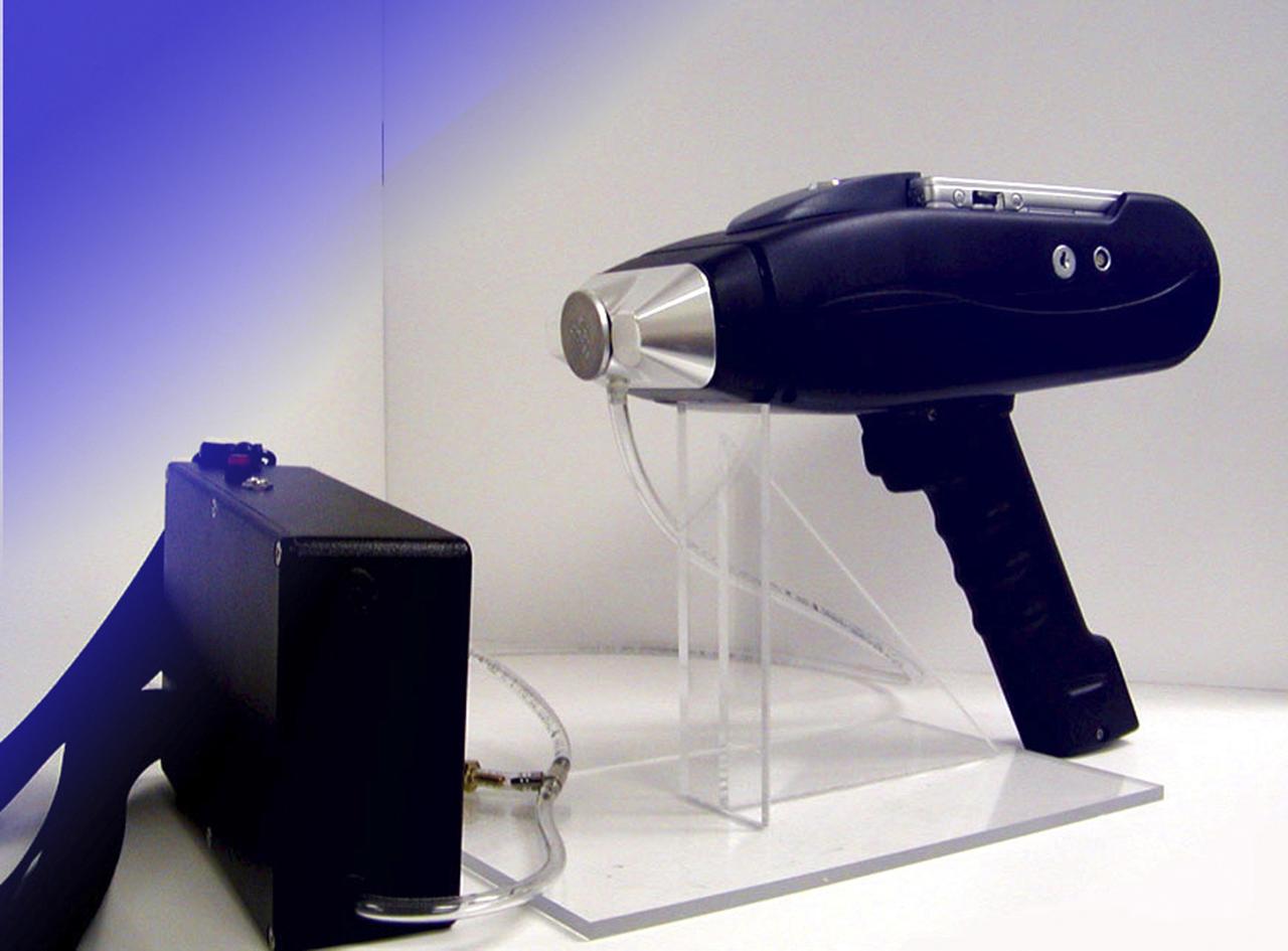
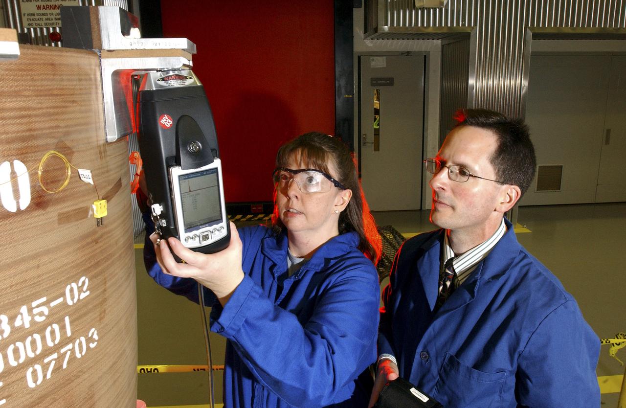
Marshall Space Flight Center engineers have teamed with KeyMaster Technologies, Kennewick, Washington, to develop a portable vacuum analyzer that performs on-the-spot chemical analyses under field conditions, a task previously only possible in a chemical laboratory. The new capability is important not only to the aerospace industry, but holds potential for broad applications in any industry that depends on materials analysis, such as the automotive and pharmaceutical industries. Weighing in at a mere 4 pounds, the newly developed handheld vacuum X-ray fluorescent analyzer can identify and characterize a wide range of elements, and is capable of detecting chemical elements with low atomic numbers, such as sodium, aluminum and silicon. It is the only handheld product on the market with that capability. Aluminum alloy verification is of particular interest to NASA because vast amounts of high-strength aluminum alloys are used in the Space Shuttle propulsion system such as the External Tank, Main Engine, and Solid Rocket Boosters. This capability promises to be a boom to the aerospace community because of unique requirements, for instance, the need to analyze Space Shuttle propulsion systems on the launch pad. Those systems provide the awe-inspiring rocket power that propels the Space Shuttle from Earth into orbit in mere minutes. The scanner development also marks a major improvement in the quality assurance field, because screws, nuts, bolts, fasteners, and other items can now be evaluated upon receipt and rejected if found to be substandard. The same holds true for aluminum weld rods. The ability to validate the integrity of raw materials and partially finished products before adding value to them in the manufacturing process will be of benefit not only to businesses, but also to the consumer, who will have access to a higher value product at a cheaper price. Three vacuum X-ray scanners are already being used in the Space Shuttle Program. The External Tank Project Office is using one for aluminum alloy analysis, while a Marshall contractor is evaluating alloys with another unit purchased for the Space Shuttle Main Engine Office. The Reusable Solid Rocket Motor Project Office has obtained a scanner that is being used to test hardware and analyze materials.
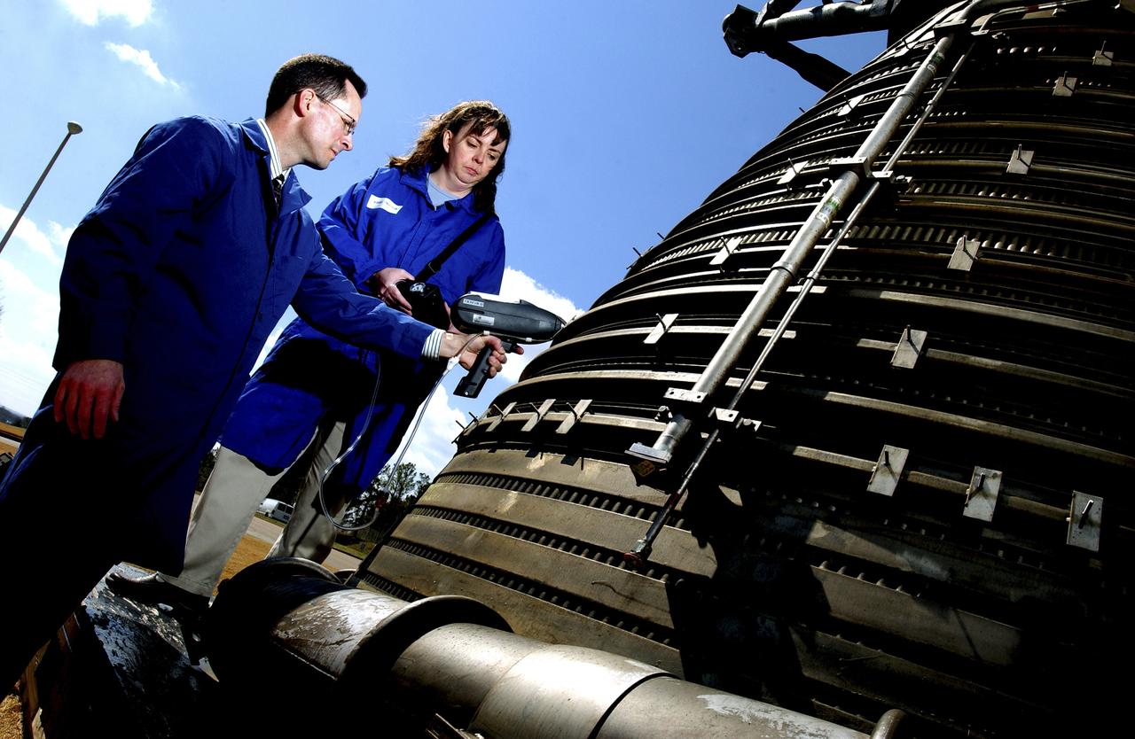
Teamed with KeyMaster Technologies, Kennewick, Washington, the Marshall Space Flight Center engineers have developed a portable vacuum analyzer that performs on-the-spot chemical analyses under field conditions— a task previously only possible in a chemical laboratory. The new capability is important not only to the aerospace industry, but holds potential for broad applications in any industry that depends on materials analysis, such as the automotive and pharmaceutical industries. Weighing in at a mere 4 pounds, the newly developed handheld vacuum X-ray fluorescent analyzer can identify and characterize a wide range of elements, and is capable of detecting chemical elements with low atomic numbers, such as sodium, aluminum and silicon. It is the only handheld product on the market with that capability. Aluminum alloy verification is of particular interest to NASA because vast amounts of high-strength aluminum alloys are used in the Space Shuttle propulsion system such as the External Tank, Main Engine, and Solid Rocket Boosters. This capability promises to be a boom to the aerospace community because of unique requirements, for instance, the need to analyze Space Shuttle propulsion systems on the launch pad. Those systems provide the awe-inspiring rocket power that propels the Space Shuttle from Earth into orbit in mere minutes. The scanner development also marks a major improvement in the quality assurance field, because screws, nuts, bolts, fasteners, and other items can now be evaluated upon receipt and rejected if found to be substandard. The same holds true for aluminum weld rods. The ability to validate the integrity of raw materials and partially finished products before adding value to them in the manufacturing process will be of benefit not only to businesses, but also to the consumer, who will have access to a higher value product at a cheaper price. Three vacuum X-ray scanners are already being used in the Space Shuttle Program. The External Tank Project Office is using one for aluminum alloy analysis, while a Marshall contractor is evaluating alloys with another unit purchased for the Space Shuttle Main Engine Office. The Reusable Solid Rocket Motor Project Office has obtained a scanner that is being used to test hardware and analyze materials. In this photograph, Richard Booth, Marshall Engineering Directorate, and Wanda Hudson, ATK Thiokol, use an enhanced vacuum X-ray fluorescent scanner to analyze materials in an F-1 engine, which was used to boost the Saturn V rocket from Earth’s orbit that carried astronauts to the moon in the 1960s.
From December 10, 1966, until his retirement on February 27, 1976, Stanley P. Butchart served as Chief (later, Director) of Flight Operations at NASA's Flight Research Center (renamed on March 26, 1976, the Hugh L. Dryden Flight Research Center). Initially, his responsibilities in this position included the Research Pilots Branch, a Maintenance and Manufacturing Branch, and an Operations Engineering Branch, the last of which not only included propulsion and electrical/electronic sections but project engineers for the X-15 and lifting bodies. During his tenure, however, the responsibilities of his directorate came to include not only Flight Test Engineering Support but Flight Systems and Loads laboratories. Before becoming Chief of Flight Operations, Butchart had served since June of 1966 as head of the Research Pilots Branch (Chief Pilot) and then as acting chief of Flight Operations. He had joined the Center (then known as the National Advisory Committee for Aeronautics' High-Speed Flight Research Station) as a research pilot on May 10, 1951. During his career as a research pilot, he flew a great variety of research and air-launch aircraft including the D-558-I, D-558-II, B-29 (plus its Navy version, the P2B), X-4, X-5, KC-135, CV-880, CV-990, B-47, B-52, B-747, F-100A, F-101, F-102, F-104, PA-30 Twin Comanche, JetStar, F-111, R4D, B-720, and B-47. Although previously a single-engine pilot, he became the Center's principal multi-engine pilot during a period of air-launches in which the pilot of the air-launch aircraft (B-29 or P2B) basically directed the operations. It was he who called for the chase planes before each drop, directed the positioning of fire rescue vehicles, and released the experimental aircraft after ensuring that all was ready for the drop. As pilot of the B-29 and P2B, Butchart launched the X-1A once, the X-1B 13 times, the X-1E 22 times, and the D-558-II 102 times. In addition, he towed the M2-F1 lightweight lifting body 14 times behind an R4
Teamed with KeyMaster Technologies, Kennewick, Washington, the Marshall Space Flight Center engineers have developed a portable vacuum analyzer that performs on-the-spot chemical analyses under field conditions— a task previously only possible in a chemical laboratory. The new capability is important not only to the aerospace industry, but holds potential for broad applications in any industry that depends on materials analysis, such as the automotive and pharmaceutical industries. Weighing in at a mere 4 pounds, the newly developed handheld vacuum X-ray fluorescent analyzer can identify and characterize a wide range of elements, and is capable of detecting chemical elements with low atomic numbers, such as sodium, aluminum and silicon. It is the only handheld product on the market with that capability. Aluminum alloy verification is of particular interest to NASA because vast amounts of high-strength aluminum alloys are used in the Space Shuttle propulsion system such as the External Tank, Main Engine, and Solid Rocket Boosters. This capability promises to be a boom to the aerospace community because of unique requirements, for instance, the need to analyze Space Shuttle propulsion systems on the launch pad. Those systems provide the awe-inspiring rocket power that propels the Space Shuttle from Earth into orbit in mere minutes. The scanner development also marks a major improvement in the quality assurance field, because screws, nuts, bolts, fasteners, and other items can now be evaluated upon receipt and rejected if found to be substandard. The same holds true for aluminum weld rods. The ability to validate the integrity of raw materials and partially finished products before adding value to them in the manufacturing process will be of benefit not only to businesses, but also to the consumer, who will have access to a higher value product at a cheaper price. Three vacuum X-ray scanners are already being used in the Space Shuttle Program. The External Tank Project Office is using one for aluminum alloy analysis, while a Marshall contractor is evaluating alloys with another unit purchased for the Space Shuttle Main Engine Office. The Reusable Solid Rocket Motor Project Office has obtained a scanner that is being used to test hardware and analyze materials. In this photograph, Wanda Hudson, left, ATK Thiokol, and Richard Booth, Marshall Engineering Directorate, use an enhanced vacuum X-ray fluorescent scanner to evaluate Reusable Solid Rocket Motor hardware.
Developed by Boeing, at the Marshall Space Flight Center (MSFC) Space Station Manufacturing building, the Window Observational Rack Facility (WORF) will help Space Station crews take some of the best photographs ever snapped from an orbiting spacecraft by eliminating glare and allowing researchers to control their cameras and other equipment from the ground. The WORF is designed to make the best possible use of the high-quality research window in the Space Station's U.S. Destiny laboratory module. Engineers at the MSFC proposed a derivative of the EXPRESS (Expedite the Processing of Experiments to the Space Station) Rack already used on the Space Station and were given the go-ahead. The EXPRESS rack can hold a wide variety of experiments and provide them with power, communications, data, cooling, fluids, and other utilities - all the things that Earth-observing experiment instruments would need. WORF will supply payloads with power, data, cooling, video downlink, and stable, standardized interfaces for mounting imaging instruments. Similar to specialized orbital observatories, the interior of the rack is sealed against light and coated with a special low-reflectant black paint, so payloads will be able to observe low-light-level subjects such as the faint glow of auroras. Cameras and remote sensing instruments in the WORF can be preprogrammed, controlled from the ground, or operated by a Station crewmember by using a flexible shroud designed to cinch tightly around the crewmember's waist. The WORF is scheduled to be launched aboard the STS-114 Space Shuttle mission in the year 2003.
CAPE CANAVERAL, Fla. - At the Shuttle Landing Facility at NASA's Kennedy Space Center in Florida, James Cawby, director of Manufacturing and Processing, Launch and Recovery Systems, United Space Alliance, congratulates STS-131 Commander Alan Poindexter on a successful mission following the landing of space shuttle Discovery on Runway 33. On Cawby's right in the receiving line is Mike Orr, director of Launch and Recovery Systems Engineering, United Space Alliance. Pete Nickolenko, NASA's STS-131 launch director is on Cawby's left. The astronauts are, from left, Mission Specialists Naoko Yamazaki of the Japan Aerospace Exploration Agency, Dorothy Metcalf-Lindenburger and Rick Mastracchio; Pilot James P. Dutton Jr.; and Poindexter. Discovery landed at Kennedy after 15 days in space, completing the more than 6.2-million-mile STS-131 mission on orbit 238. Main gear touchdown was at 9:08:35 a.m. EDT followed by nose gear touchdown at 9:08:47 a.m. and wheelstop at 9:09:33 a.m. The seven-member STS-131 crew carried the multi-purpose logistics module Leonardo, filled with supplies, a new crew sleeping quarters and science racks that were transferred to the International Space Station's laboratories. The crew also switched out a gyroscope on the station’s truss, installed a spare ammonia storage tank and retrieved a Japanese experiment from the station’s exterior. STS-131 is the 33rd shuttle mission to the station and the 131st shuttle mission overall. For information on the STS-131 mission and crew, visit http:__www.nasa.gov_mission_pages_shuttle_shuttlemissions_sts131_index.html. Photo credit: NASA_Jim Grossmann
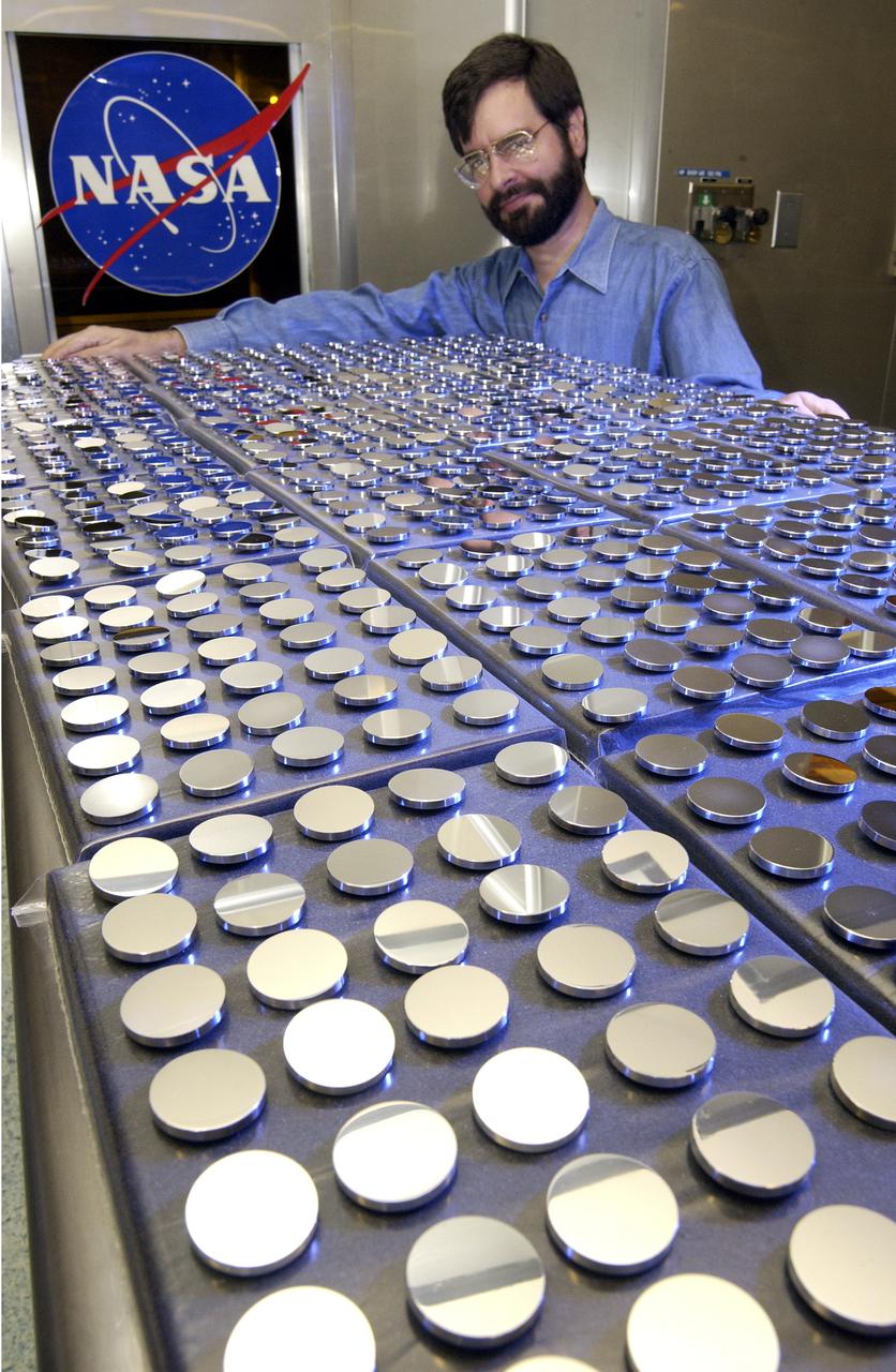
In this photograph, Vince Huegele of the Marshall Space Flight Center's (MSFC's) Space Optics Manufacturing Technology Center (SOMTC) inspects the coating on the mirrors for Starshine 3, a satellite that resembles a high-tech disco ball that was placed into Earth orbit. The sphere, which is covered by hundreds of quarter-sized mirrors that reflect sunlight to observers on the ground, helps students study the effects of solar activity on the Earth's atmosphere. Ed White Middle School in Huntsville, Alabama is among 500 schools worldwide whose students helped grind and polish mirrors for the Starshine 3 satellite as a part of the Starshine Project. The total of up to 1,500 mirrors will improve the sunlight flash rate and make the satellite more visible at twilight as it orbits the Earth. These mirrors have been coated with a scratch-resistant, anti-oxidizing layer of silicon dioxide by optical engineers and technicians at the Hill Air Force Base in Utah and MSFC. Starshine-3 was launched on an Athena I unmarned launch vehicle out of the Kodiak Launch Complex, Alaska, on September 29, 2001. Starshine 3 is nearly 37 inches (1 meter) in diameter, weighs 200 pounds (91 kilograms), and carries 1500 mirrors that were polished by approximately 40,000 students in 1,000 schools in 30 countries. Three small, optically-reflective spherical Starshine student satellites have been designed by the U.S. Naval Research Laboratory and built by an informal volunteer coalition of organizations and individuals in the U.S. and Canada. This coalition, called Project Starshine, is headquartered in Monument, Colorado.