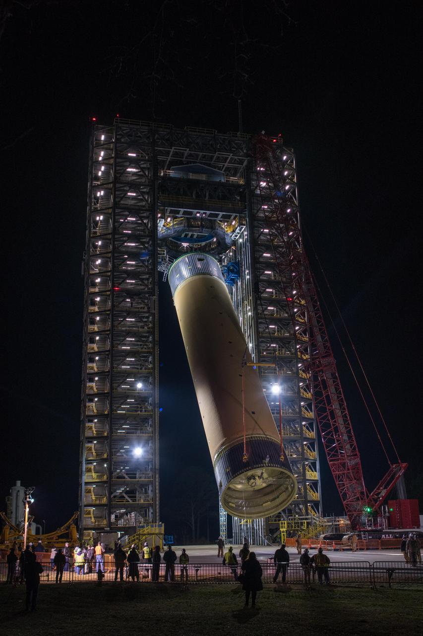
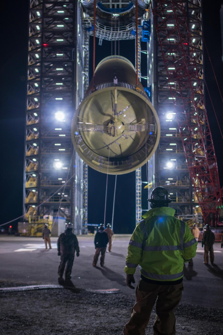
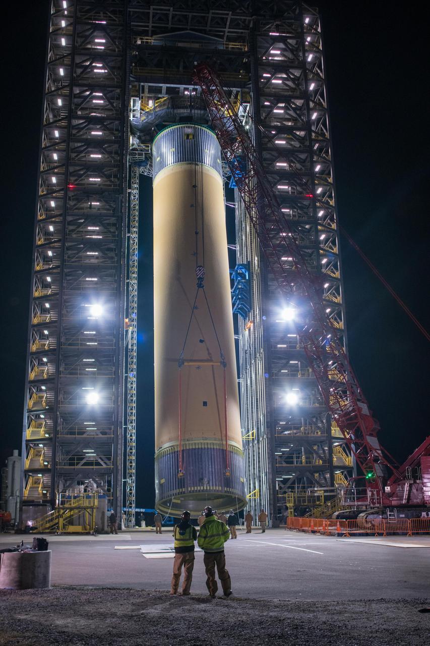
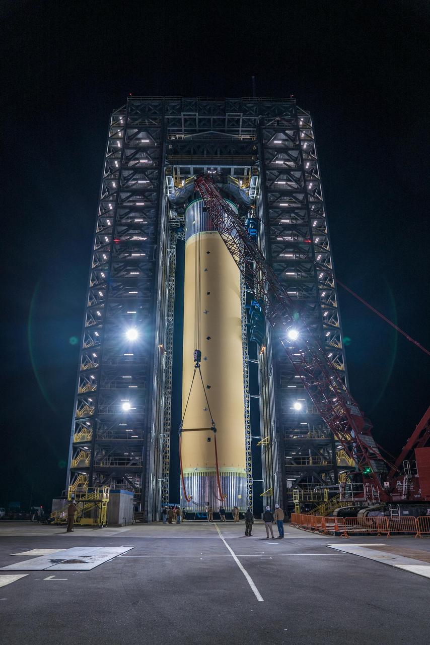
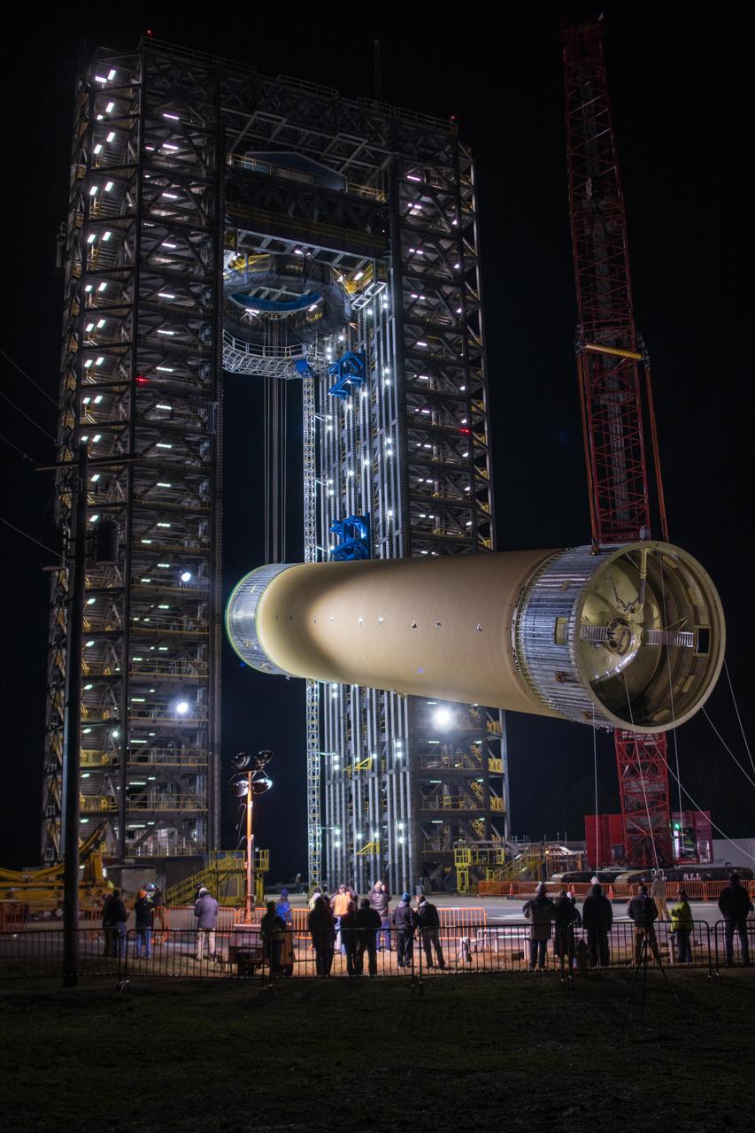
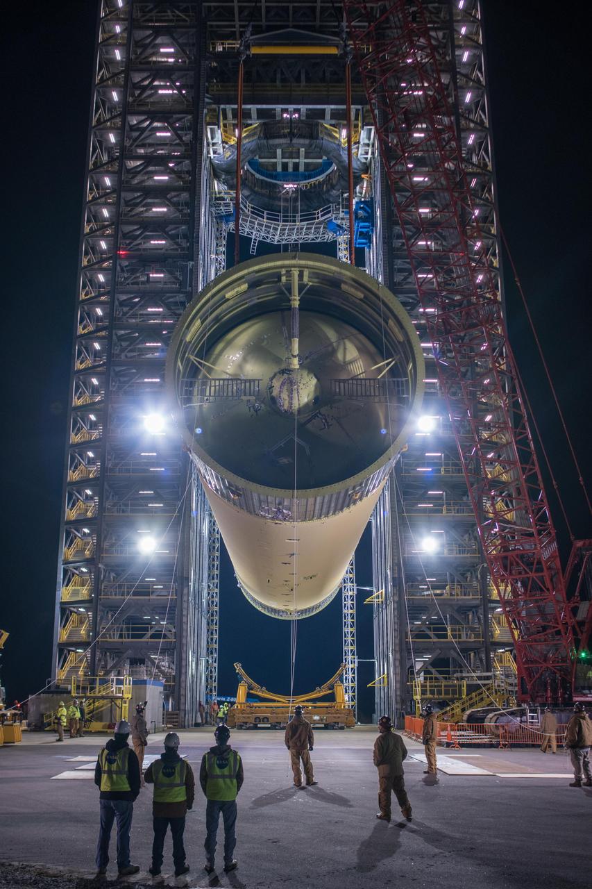
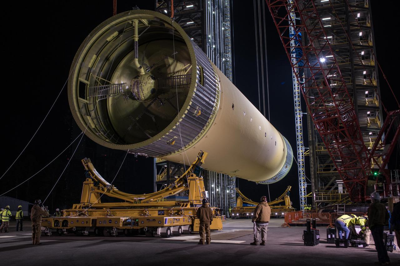
The Space Launch System (SLS) liquid hydrogen tank structural test article is loaded into Test Stand 4693 at NASA’s Marshall Space Flight Center in Huntsville, Alabama, on Jan. 14, 2019. The 149-foot piece of test hardware is the largest piece of structural hardware for the SLS core stage for America’s new deep space rocket Itis structurally identical to the flight version of the tank. It will undergo a series of tests in Test Stand 4693 to simulate the stresses and loads of liftoff and flight. These tests will help ensure designs are adequate for successful SLS missions to the Moon and beyond.
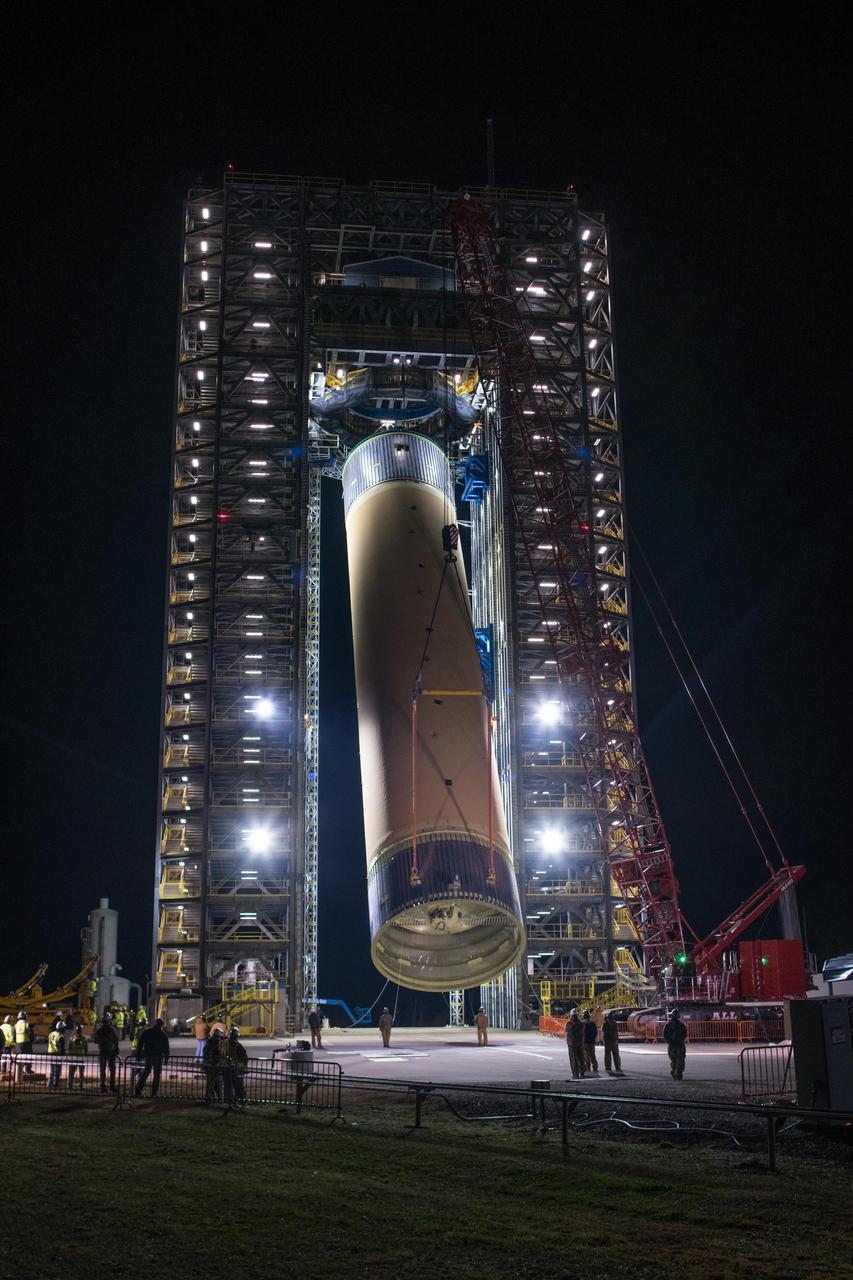
The Space Launch System (SLS) liquid hydrogen tank structural test article is loaded into Test Stand 4693 at NASA’s Marshall Space Flight Center in Huntsville, Alabama, on Jan. 14, 2019. The 149-foot piece of test hardware is the largest piece of structural hardware for the SLS core stage for America’s new deep space rocket Itis structurally identical to the flight version of the tank. It will undergo a series of tests in Test Stand 4693 to simulate the stresses and loads of liftoff and flight. These tests will help ensure designs are adequate for successful SLS missions to the Moon and beyond.
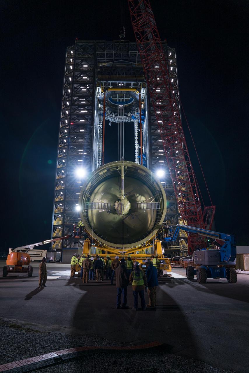
The Space Launch System (SLS) liquid hydrogen tank structural test article is loaded into Test Stand 4693 at NASA’s Marshall Space Flight Center in Huntsville, Alabama, on Jan. 14, 2019. The 149-foot piece of test hardware is the largest piece of structural hardware for the SLS core stage for America’s new deep space rocket Itis structurally identical to the flight version of the tank. It will undergo a series of tests in Test Stand 4693 to simulate the stresses and loads of liftoff and flight. These tests will help ensure designs are adequate for successful SLS missions to the Moon and beyond.
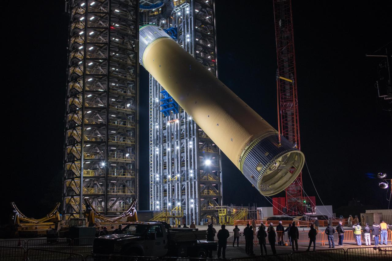
The Space Launch System (SLS) liquid hydrogen tank structural test article is loaded into Test Stand 4693 at NASA’s Marshall Space Flight Center in Huntsville, Alabama, on Jan. 14, 2019. The 149-foot piece of test hardware is the largest piece of structural hardware for the SLS core stage for America’s new deep space rocket Itis structurally identical to the flight version of the tank. It will undergo a series of tests in Test Stand 4693 to simulate the stresses and loads of liftoff and flight. These tests will help ensure designs are adequate for successful SLS missions to the Moon and beyond.
The Space Launch System (SLS) liquid hydrogen tank structural test article is loaded into Test Stand 4693 at NASA’s Marshall Space Flight Center in Huntsville, Alabama, on Jan. 14, 2019. The 149-foot piece of test hardware is the largest piece of structural hardware for the SLS core stage for America’s new deep space rocket Itis structurally identical to the flight version of the tank. It will undergo a series of tests in Test Stand 4693 to simulate the stresses and loads of liftoff and flight. These tests will help ensure designs are adequate for successful SLS missions to the Moon and beyond.
The Space Launch System (SLS) liquid hydrogen tank structural test article is loaded into Test Stand 4693 at NASA’s Marshall Space Flight Center in Huntsville, Alabama, on Jan. 14, 2019. The 149-foot piece of test hardware is the largest piece of structural hardware for the SLS core stage for America’s new deep space rocket Itis structurally identical to the flight version of the tank. It will undergo a series of tests in Test Stand 4693 to simulate the stresses and loads of liftoff and flight. These tests will help ensure designs are adequate for successful SLS missions to the Moon and beyond.
The Space Launch System (SLS) liquid hydrogen tank structural test article is loaded into Test Stand 4693 at NASA’s Marshall Space Flight Center in Huntsville, Alabama, on Jan. 14, 2019. The 149-foot piece of test hardware is the largest piece of structural hardware for the SLS core stage for America’s new deep space rocket Itis structurally identical to the flight version of the tank. It will undergo a series of tests in Test Stand 4693 to simulate the stresses and loads of liftoff and flight. These tests will help ensure designs are adequate for successful SLS missions to the Moon and beyond.
The Space Launch System (SLS) liquid hydrogen tank structural test article is loaded into Test Stand 4693 at NASA’s Marshall Space Flight Center in Huntsville, Alabama, on Jan. 14, 2019. The 149-foot piece of test hardware is the largest piece of structural hardware for the SLS core stage for America’s new deep space rocket Itis structurally identical to the flight version of the tank. It will undergo a series of tests in Test Stand 4693 to simulate the stresses and loads of liftoff and flight. These tests will help ensure designs are adequate for successful SLS missions to the Moon and beyond.
The Space Launch System (SLS) liquid hydrogen tank structural test article is loaded into Test Stand 4693 at NASA’s Marshall Space Flight Center in Huntsville, Alabama, on Jan. 14, 2019. The 149-foot piece of test hardware is the largest piece of structural hardware for the SLS core stage for America’s new deep space rocket Itis structurally identical to the flight version of the tank. It will undergo a series of tests in Test Stand 4693 to simulate the stresses and loads of liftoff and flight. These tests will help ensure designs are adequate for successful SLS missions to the Moon and beyond.
The Space Launch System (SLS) liquid hydrogen tank structural test article is loaded into Test Stand 4693 at NASA’s Marshall Space Flight Center in Huntsville, Alabama, on Jan. 14, 2019. The 149-foot piece of test hardware is the largest piece of structural hardware for the SLS core stage for America’s new deep space rocket Itis structurally identical to the flight version of the tank. It will undergo a series of tests in Test Stand 4693 to simulate the stresses and loads of liftoff and flight. These tests will help ensure designs are adequate for successful SLS missions to the Moon and beyond.
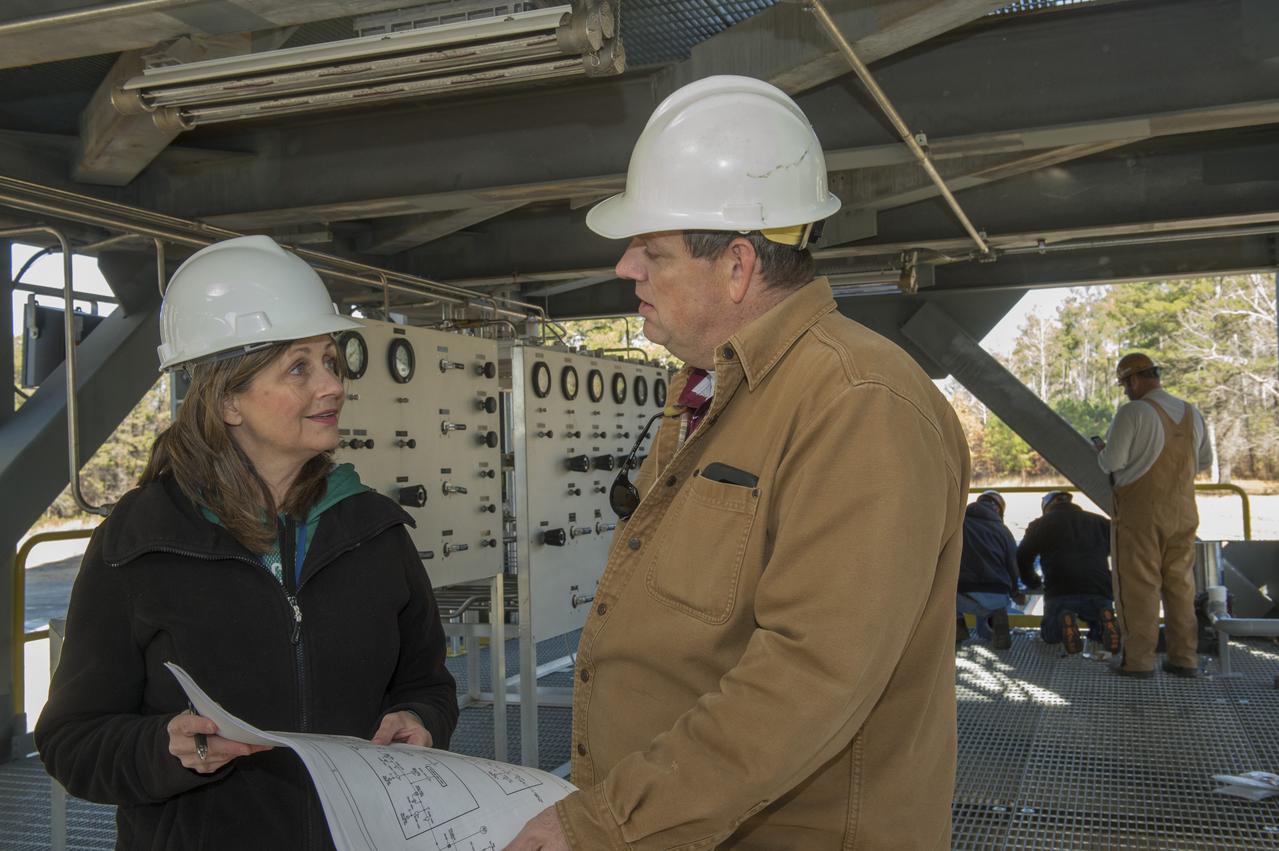
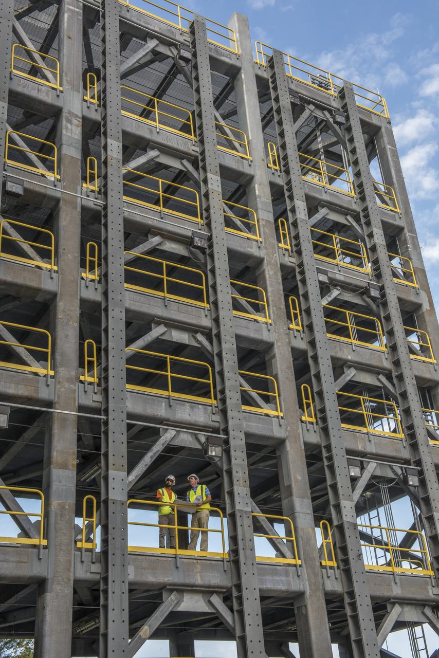
TARA MARSHALL, LEFT, A MARSHALL ENGINEER, TALKS ABOUT THE INSTALLATION OF A PRESSURIZATION CONTROL PANEL AT TEST STAND 4693 WITH MIKE NICHOLS, LEAD TEST ENGINEER FOR THE SPACE LAUNCH SYSTEM LIQUID HYDROGEN TANK STRUCTURAL TEST ARTICLE.
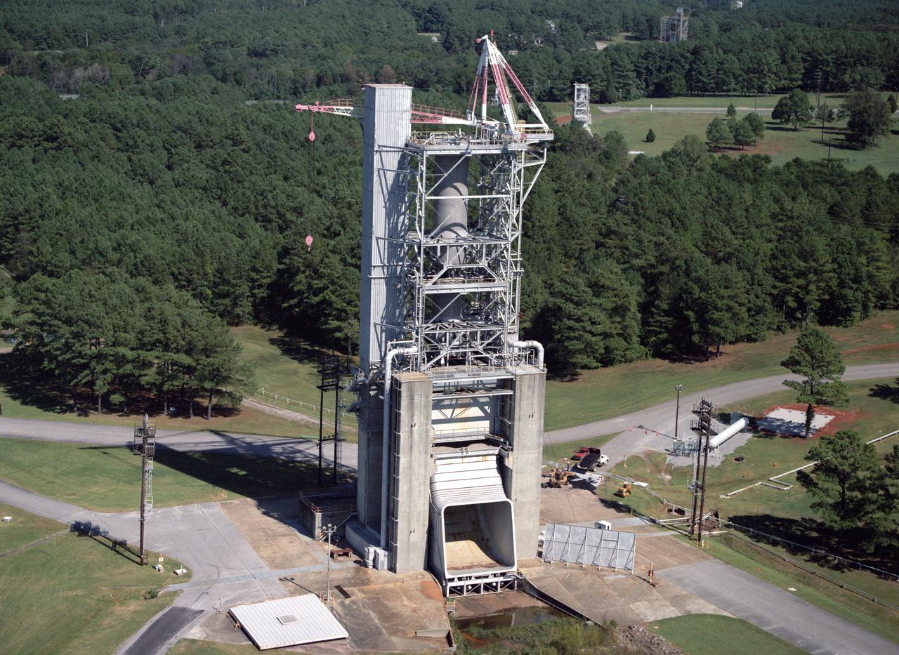
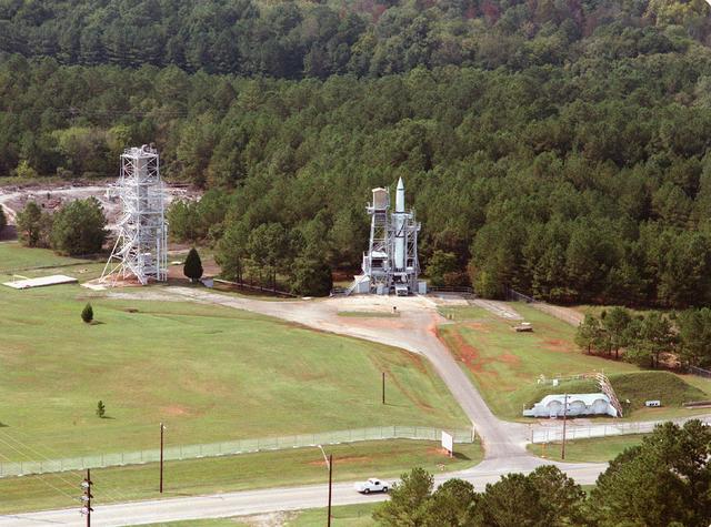
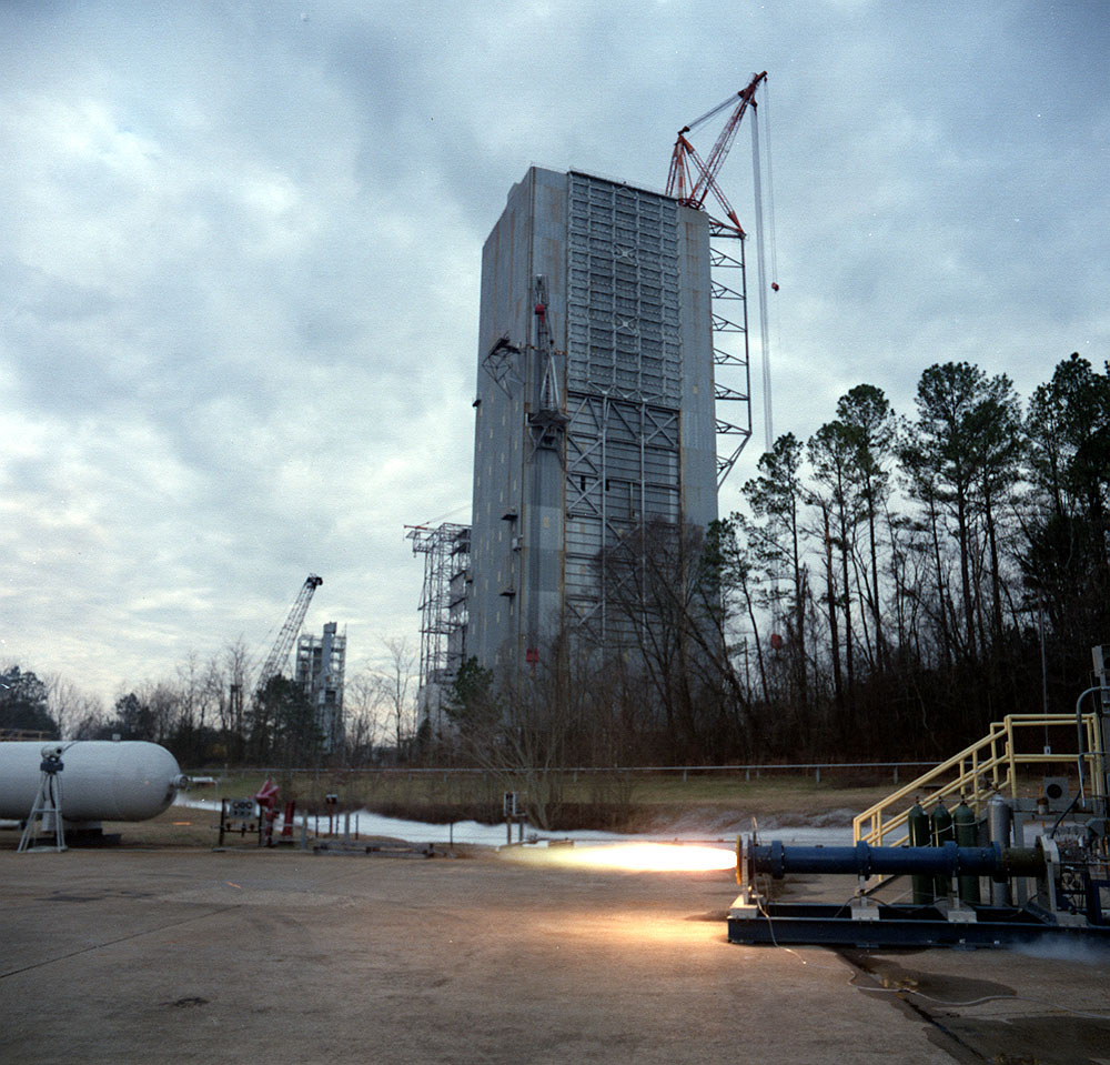
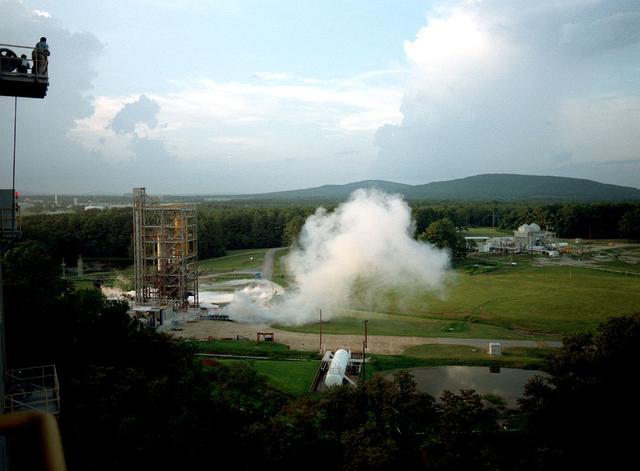
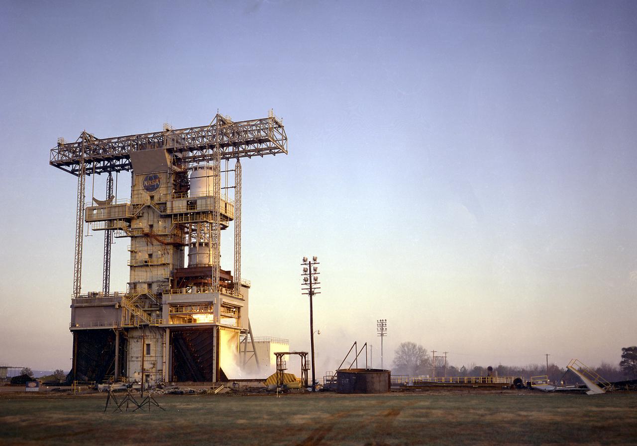
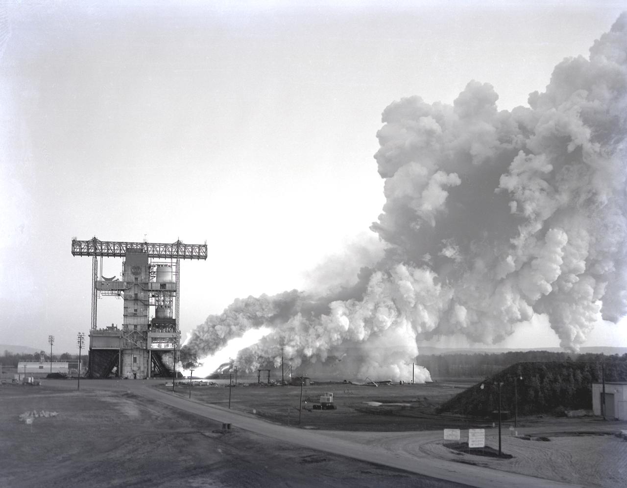
Marshall Space Flight Center's F-1 Engine Test Stand is shown in this picture. Constructed in 1963, the test stand is a vertical engine firing test stand, 239 feet in elevation and 4,600 square feet in area at the base, and was designed to assist in the development of the F-1 Engine. Capability is provided for static firing of 1.5 million pounds of thrust using liquid oxygen and kerosene. The foundation of the stand is keyed into the bedrock approximately 40 feet below grade.
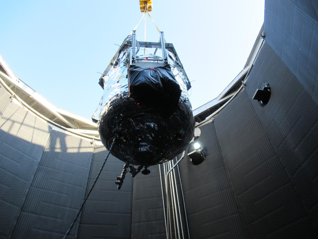
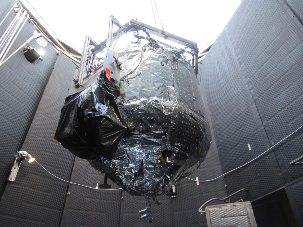
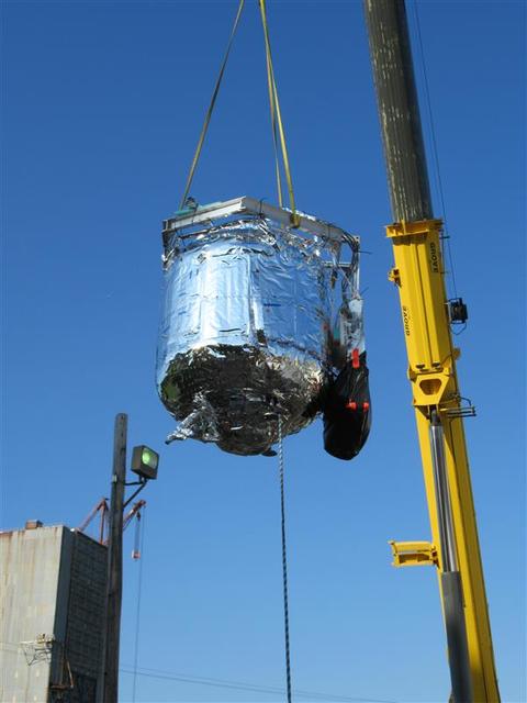
These photos show how teams at NASA’s Marshall Space Flight Center in Huntsville, Alabama, are testing an innovative approach to achieve zero boiloff storage of liquid hydrogen using two stages of active cooling, which could prevent the loss of valuable propellant during future long-duration spaceflight missions. Test teams installed the propellant tank in Test Stand 300 at NASA Marshall in early June, and the 90-day test campaign is scheduled to conclude in September. The tank is wrapped in a multi-layer insulation blanket that includes a thin aluminum heat shield fitted between layers. A second set of tubes, carrying helium at about minus 298 Fahrenheit, is integrated into the shield. This intermediate cooling layer intercepts and rejects incoming heat before it reaching the tank, easing the heat load on the tube-on-tank system. The Cryogenic Fluid Management Portfolio Project is a cross-agency team based at NASA Marshall and the agency’s Glenn Research Center in Cleveland. The cryogenic portfolio’s work is under NASA’s Technology Demonstration Missions Program, part of NASA’s Space Technology Mission Directorate, and is comprised of more than 20 individual technology development activities. For more information, contact NASA Marshall’s Office of Communications at 256-544-0034.
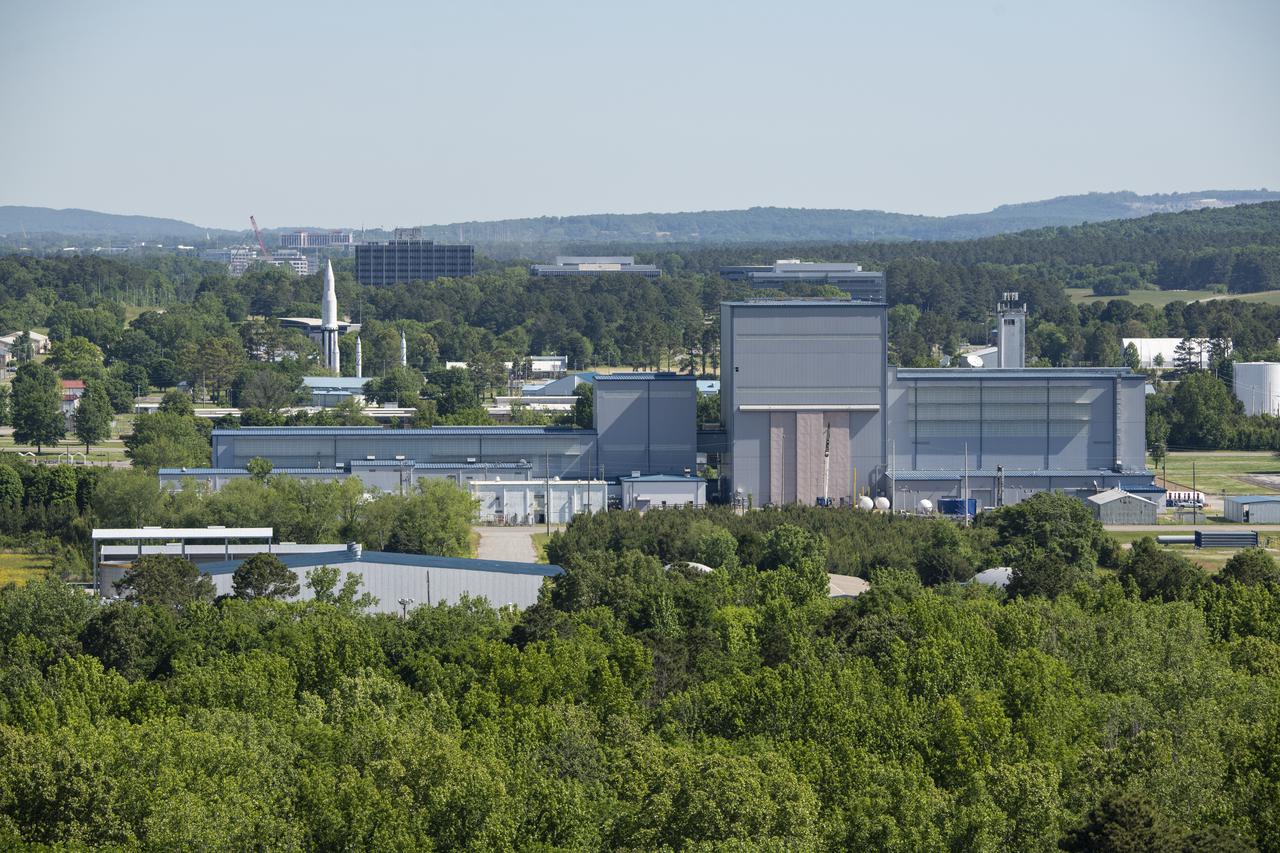
Pictured is a view of Marshall Space Flight Center’s campus from atop test stand Building 4693.
These photos show how teams at NASA’s Marshall Space Flight Center in Huntsville, Alabama, are testing an innovative approach to achieve zero boiloff storage of liquid hydrogen using two stages of active cooling, which could prevent the loss of valuable propellant during future long-duration spaceflight missions. Test teams installed the propellant tank in Test Stand 300 at NASA Marshall in early June, and the 90-day test campaign is scheduled to conclude in September. The tank is wrapped in a multi-layer insulation blanket that includes a thin aluminum heat shield fitted between layers. A second set of tubes, carrying helium at about minus 298 Fahrenheit, is integrated into the shield. This intermediate cooling layer intercepts and rejects incoming heat before it reaching the tank, easing the heat load on the tube-on-tank system. The Cryogenic Fluid Management Portfolio Project is a cross-agency team based at NASA Marshall and the agency’s Glenn Research Center in Cleveland. The cryogenic portfolio’s work is under NASA’s Technology Demonstration Missions Program, part of NASA’s Space Technology Mission Directorate, and is comprised of more than 20 individual technology development activities. For more information, contact NASA Marshall’s Office of Communications at 256-544-0034.

These photos show how teams at NASA’s Marshall Space Flight Center in Huntsville, Alabama, are testing an innovative approach to achieve zero boiloff storage of liquid hydrogen using two stages of active cooling, which could prevent the loss of valuable propellant during future long-duration spaceflight missions. Test teams installed the propellant tank in Test Stand 300 at NASA Marshall in early June, and the 90-day test campaign is scheduled to conclude in September. The tank is wrapped in a multi-layer insulation blanket that includes a thin aluminum heat shield fitted between layers. A second set of tubes, carrying helium at about minus 298 Fahrenheit, is integrated into the shield. This intermediate cooling layer intercepts and rejects incoming heat before it reaching the tank, easing the heat load on the tube-on-tank system. The Cryogenic Fluid Management Portfolio Project is a cross-agency team based at NASA Marshall and the agency’s Glenn Research Center in Cleveland. The cryogenic portfolio’s work is under NASA’s Technology Demonstration Missions Program, part of NASA’s Space Technology Mission Directorate, and is comprised of more than 20 individual technology development activities. For more information, contact NASA Marshall’s Office of Communications at 256-544-0034.
These photos show how teams at NASA’s Marshall Space Flight Center in Huntsville, Alabama, are testing an innovative approach to achieve zero boiloff storage of liquid hydrogen using two stages of active cooling, which could prevent the loss of valuable propellant during future long-duration spaceflight missions. Test teams installed the propellant tank in Test Stand 300 at NASA Marshall in early June, and the 90-day test campaign is scheduled to conclude in September. The tank is wrapped in a multi-layer insulation blanket that includes a thin aluminum heat shield fitted between layers. A second set of tubes, carrying helium at about minus 298 Fahrenheit, is integrated into the shield. This intermediate cooling layer intercepts and rejects incoming heat before it reaching the tank, easing the heat load on the tube-on-tank system. The Cryogenic Fluid Management Portfolio Project is a cross-agency team based at NASA Marshall and the agency’s Glenn Research Center in Cleveland. The cryogenic portfolio’s work is under NASA’s Technology Demonstration Missions Program, part of NASA’s Space Technology Mission Directorate, and is comprised of more than 20 individual technology development activities. For more information, contact NASA Marshall’s Office of Communications at 256-544-0034.
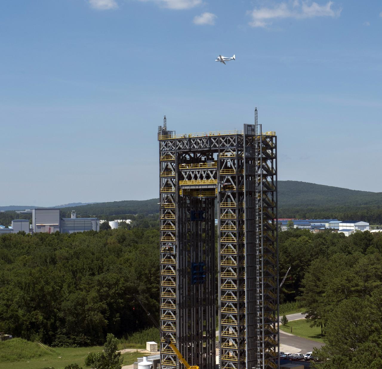
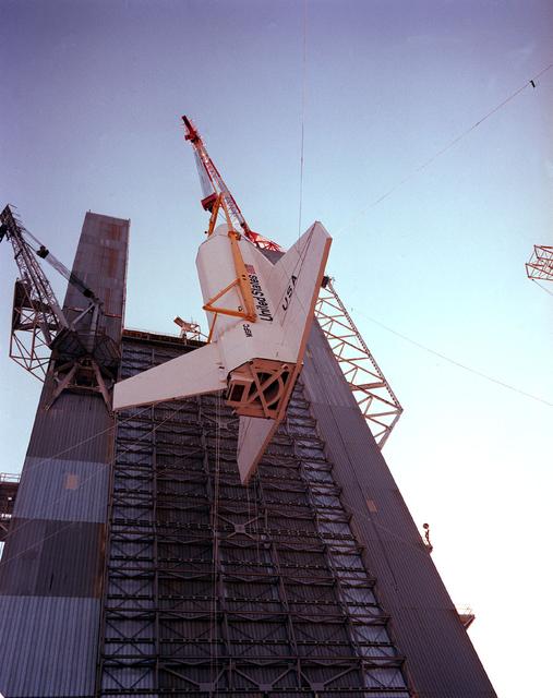
NASA's Super Guppie flies over Marshall Space Flight Center's test stand 4693 in the west test area.
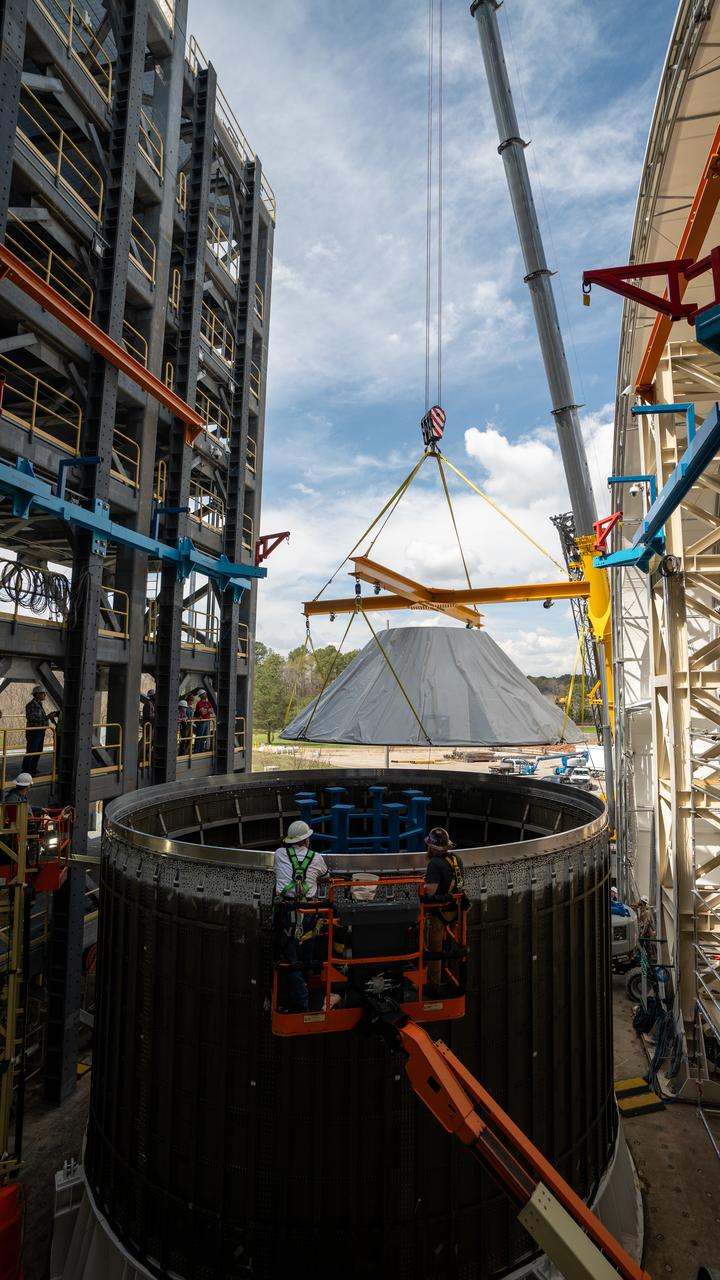
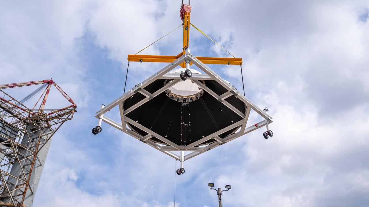
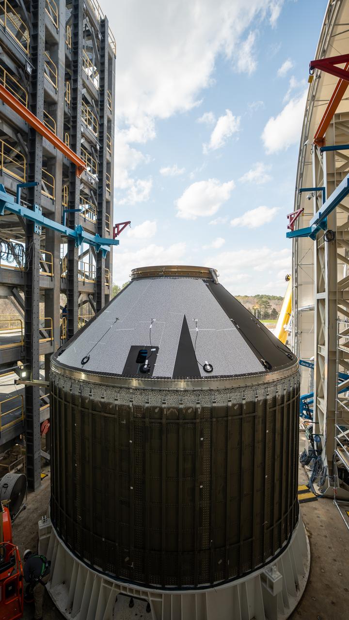
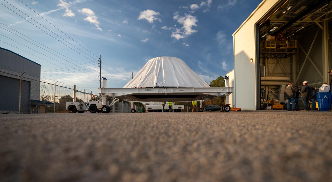
These photos and videos show how crews at NASA’s Marshall Space Flight Center in Huntsville, Alabama, moved and installed the payload adapter that will be used in the Block 1B configuration of the SLS (Space Launch System) rocket from Building 4708, where it was manufactured, into Structural Test Stand 4697 at NASA’s Marshall Space Flight Center on March 13. Teams at Marshall will begin structural testing the engineering development unit of the payload adapter – an exact replica of the flight version of the hardware – this spring. The cone-shaped payload adapter is about 8.5 feet tall and features two metal rings and eight composite panels. The adapter, which will debut on NASA’s Artemis IV mission, is an evolution from the Orion stage adapter used in the Block 1 configuration of the first three Artemis missions. It will be housed inside the universal stage adapter atop the rocket’s more powerful in-space stage, called the exploration upper stage. The payload adapter, like the launch vehicle stage adapter and the Orion stage adapter, is fully manufactured and tested at Marshall, which manages the SLS Program. NASA is working to land the first woman, first person of color, and its first international partner astronaut on the Moon under Artemis. SLS is part of NASA’s backbone for deep space exploration, along with the Orion spacecraft and Gateway in orbit around the Moon and commercial human landing systems, next-generational spacesuits, and rovers on the lunar surface. SLS is the only rocket that can send Orion, astronauts, and supplies to the Moon in a single launch.
Crews at NASA’s Marshall Space Flight Center in Huntsville, Alabama, moved and installed the payload adapter that will be used in the Block 1B configuration of the SLS (Space Launch System) rocket from Building 4708, where it was manufactured, into Structural Test Stand 4697 at NASA’s Marshall Space Flight Center on March 13.
These photos and videos show how crews at NASA’s Marshall Space Flight Center in Huntsville, Alabama, moved and installed the payload adapter that will be used in the Block 1B configuration of the SLS (Space Launch System) rocket from Building 4708, where it was manufactured, into Structural Test Stand 4697 at NASA’s Marshall Space Flight Center on March 13. Teams at Marshall will begin structural testing the engineering development unit of the payload adapter – an exact replica of the flight version of the hardware – this spring. The cone-shaped payload adapter is about 8.5 feet tall and features two metal rings and eight composite panels. The adapter, which will debut on NASA’s Artemis IV mission, is an evolution from the Orion stage adapter used in the Block 1 configuration of the first three Artemis missions. It will be housed inside the universal stage adapter atop the rocket’s more powerful in-space stage, called the exploration upper stage. The payload adapter, like the launch vehicle stage adapter and the Orion stage adapter, is fully manufactured and tested at Marshall, which manages the SLS Program. NASA is working to land the first woman, first person of color, and its first international partner astronaut on the Moon under Artemis. SLS is part of NASA’s backbone for deep space exploration, along with the Orion spacecraft and Gateway in orbit around the Moon and commercial human landing systems, next-generational spacesuits, and rovers on the lunar surface. SLS is the only rocket that can send Orion, astronauts, and supplies to the Moon in a single launch.
These photos and videos show how crews at NASA’s Marshall Space Flight Center in Huntsville, Alabama, moved and installed the payload adapter that will be used in the Block 1B configuration of the SLS (Space Launch System) rocket from Building 4708, where it was manufactured, into Structural Test Stand 4697 at NASA’s Marshall Space Flight Center on March 13. Teams at Marshall will begin structural testing the engineering development unit of the payload adapter – an exact replica of the flight version of the hardware – this spring. The cone-shaped payload adapter is about 8.5 feet tall and features two metal rings and eight composite panels. The adapter, which will debut on NASA’s Artemis IV mission, is an evolution from the Orion stage adapter used in the Block 1 configuration of the first three Artemis missions. It will be housed inside the universal stage adapter atop the rocket’s more powerful in-space stage, called the exploration upper stage. The payload adapter, like the launch vehicle stage adapter and the Orion stage adapter, is fully manufactured and tested at Marshall, which manages the SLS Program. NASA is working to land the first woman, first person of color, and its first international partner astronaut on the Moon under Artemis. SLS is part of NASA’s backbone for deep space exploration, along with the Orion spacecraft and Gateway in orbit around the Moon and commercial human landing systems, next-generational spacesuits, and rovers on the lunar surface. SLS is the only rocket that can send Orion, astronauts, and supplies to the Moon in a single launch.
The Redstone Test Stand, shown here, was used throughout the 1950s to test the Redstone missionile, including the modified Redstone that launched America's first astronaut, Alan Shepard. The U. S. Department of the Interior's Park Services designated the Test Stand as a National Historic Landmark January 22, 1986.
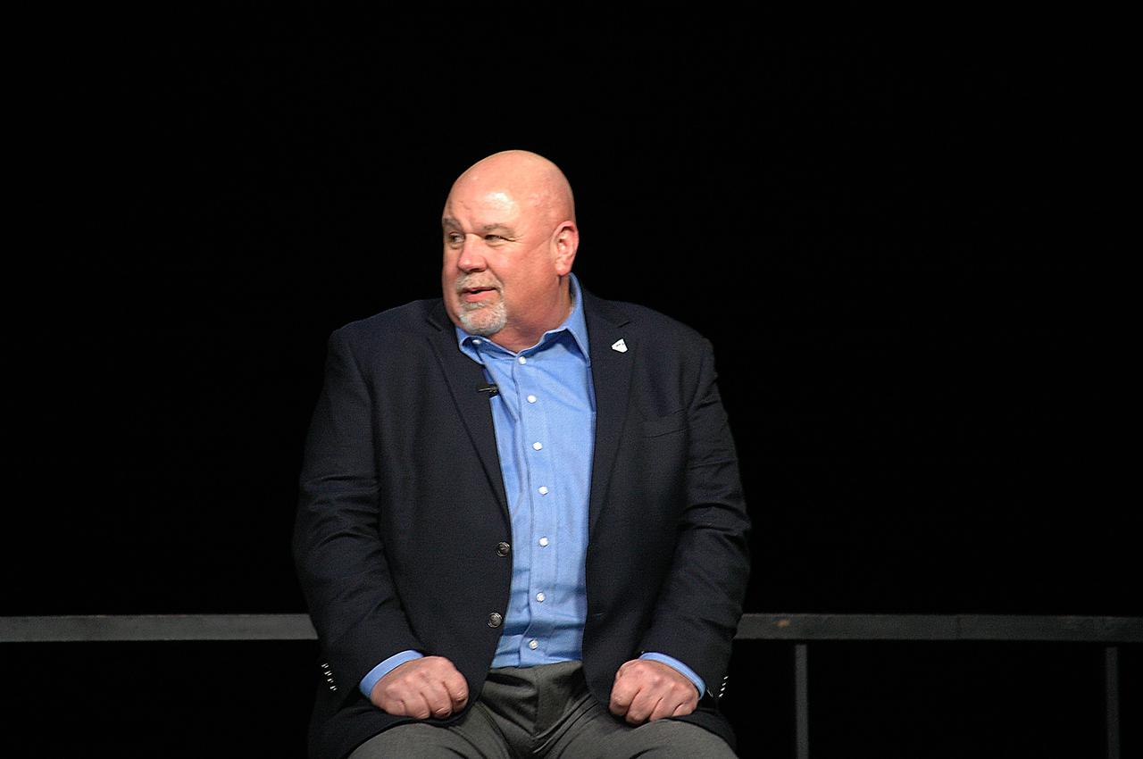
SLS Program Manager John Honeycutt from NASA’s Marshall Space Flight Center participates in a press conference following the Green Run hot fire test of the core stage for NASA’s Space Launch System (SLS) rocket on Saturday, January 16, 2021. NASA conducted a hot fire test of the core stage’s four RS-25 engines on the B-2 Test Stand at Stennis Space Center near Bay St. Louis, Mississippi. Scheduled for as long as eight minutes, the engines fired for a little more than one minute to generate a combined 1.6 million pounds of thrust, just as will occur during an actual launch. The hot fire is the final test of the Green Run test series, a comprehensive assessment of the SLS core stage prior to launching the Artemis I mission to the Moon.
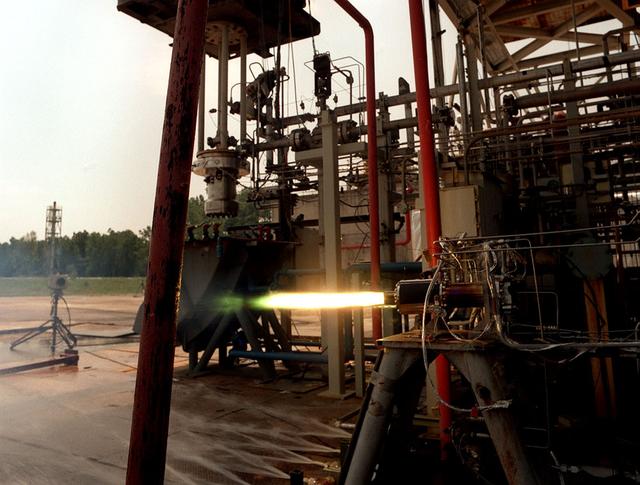
A 40K Pratt Whitney engine for the National Launch System is test fired at Marshall's Test Stand 116.
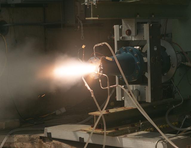
Solid fuel test performed on the Fastrac II engine cell at Marshall's Test Stand 116.

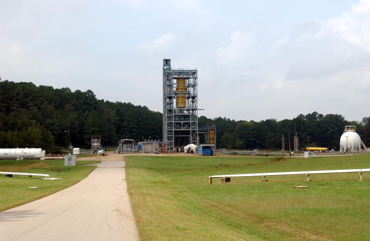
LH2 STA in NASA Marshall Space Flight Center West Test Area Test Stand.

LH2 STA in NASA Marshall Space Flight Center West Test Area Test Stand.

LH2 STA in NASA Marshall Space Flight Center West Test Area Test Stand.
A J-2 Gas Generator (GG) engine's duration test at Marshall's Test Stand-116.

LH2 STA in NASA Marshall Space Flight Center West Test Area Test Stand.
An 11 inch (11) hybrid motor fuel grain variation test firing at Marshall's Test Stand 500.

LH2 STA in NASA Marshall Space Flight Center West Test Area Test Stand.
750 K motor is test fired at Marshall Test Stand 116 for the Air Force Expendable Launch Vehicle (ELV) project.

LH2 STA in NASA Marshall Space Flight Center West Test Area Test Stand.
A 60 K Bantam Fastrac Gas Generator test at Marshall's Test Stand-116.
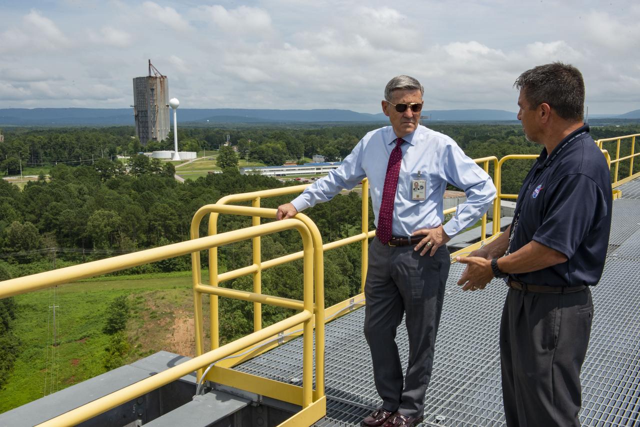
NASA's Kennedy Space Center Director Robert Cabana visited Marshall Space Flight Center July 16. With the Dynamic Test Stand in the background, Cabana, left, talks with Tim Flores, integration manager for stages in the Space Launch System Program Office, on top of Test Stand 4693, NASA’s largest SLS structural test stand. In addition to viewing SLS hardware, Cabana spoke to the Marshall Association and National Space Club Huntsville during his visit.
Pictured is a dual position Saturn I/IB test at the T-Stand at Marshall Space Flight Center. This stand was built to test two articles at the same time, thus providing engineers at MSFC with the opportunity to compare identical burns.
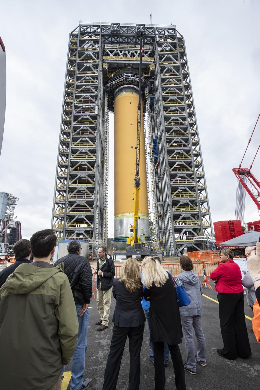
More than 700 NASA Marshall Space Flight Center team members, Boeing employees, Team Redstone participants and local officials filled 17 buses Feb. 6 to view the liquid hydrogen tank structural test article installed in Test Stand 4693 at Marshall. The 149-foot liquid hydrogen tank structural test article is the largest piece of structural test hardware for the core stage of NASA’s Space Launch System (SLS). At 221 feet tall, Test Stand 4693 is the largest test stand at Marshall -- as well as one of the newest. During testing, dozens of hydraulic cylinders in the test stand will push and pull on the tank to simulate the stresses and loads it will endure during liftoff and flight for lunar missions.
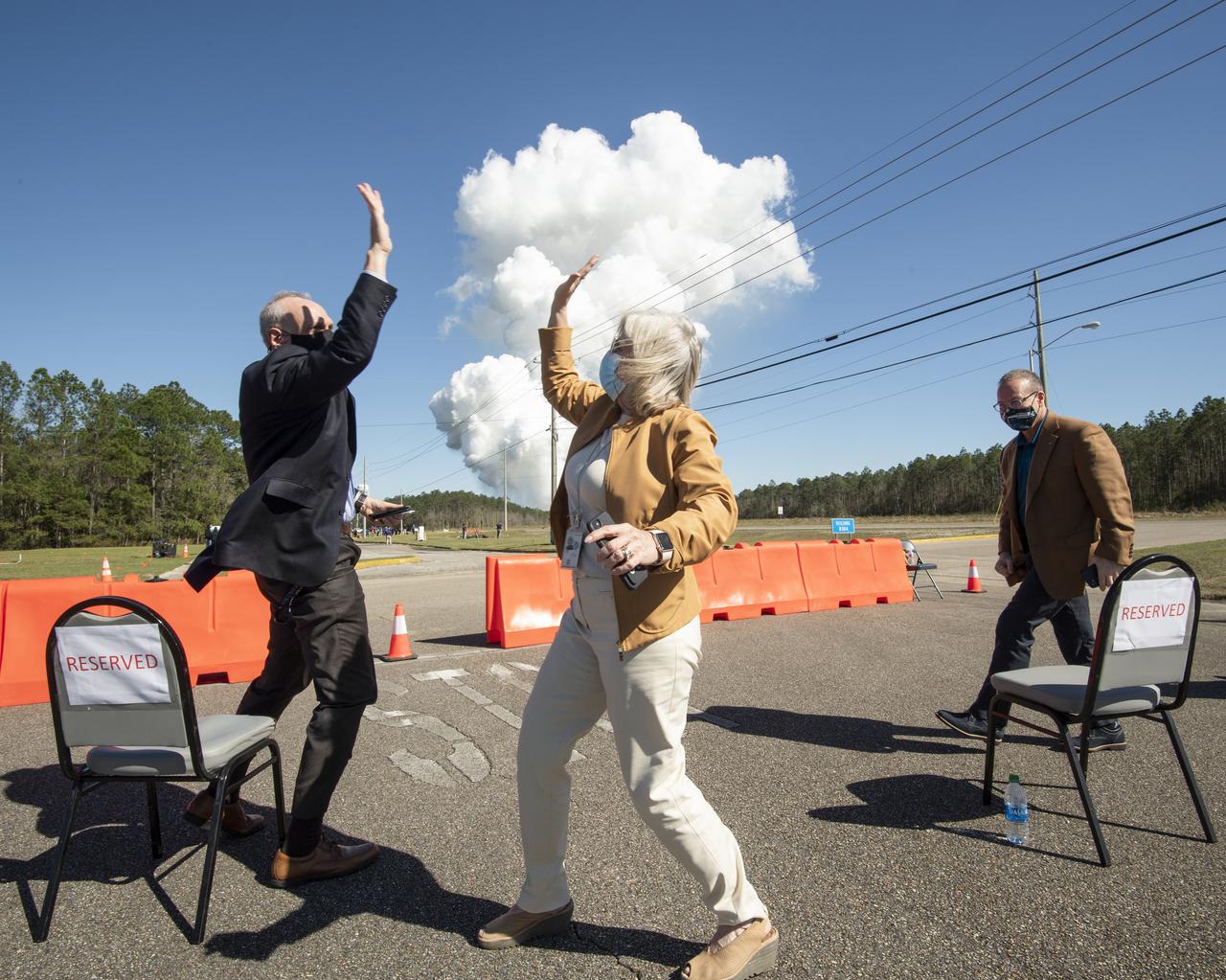
Acting NASA Administrator Steve Jurczyk, left, and Jody Singer, director of NASA's Marshall Space Flight Center, right, high five following a second hot fire test of the core stage for the first flight of NASA’s Space Launch System rocket in the B-2 Test Stand, Thursday, March 18, 2021, at NASA’s Stennis Space Center near Bay St. Louis, Mississippi. The four RS-25 engines fired for the full-duration of 8 minutes during the test and generated 1.6 million pounds of thrust. The hot fire test is the final stage of the Green Run test series, a comprehensive assessment of the Space Launch System’s core stage prior to launching the Artemis I mission to the Moon. Photo Credit: (NASA/Robert Markowitz)
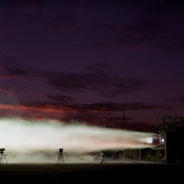
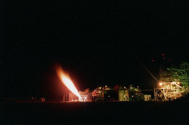
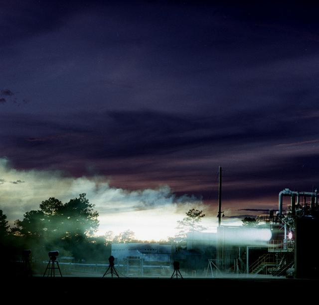
As the sun sets across the Alabama country side, engineers at Marshall's Test Stand 116 perform an endurance test on a 750K experimental engine.
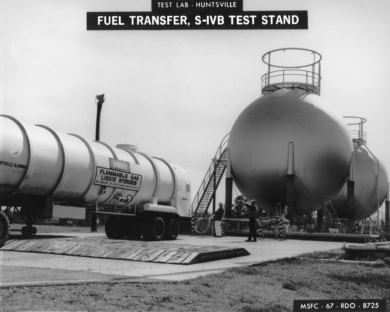
Marshall Space Flight Center (MSFC) workers fill fuel tanks with liquid hydrogen used for test firing at the S-IVB (Dynamic) Test Stand.

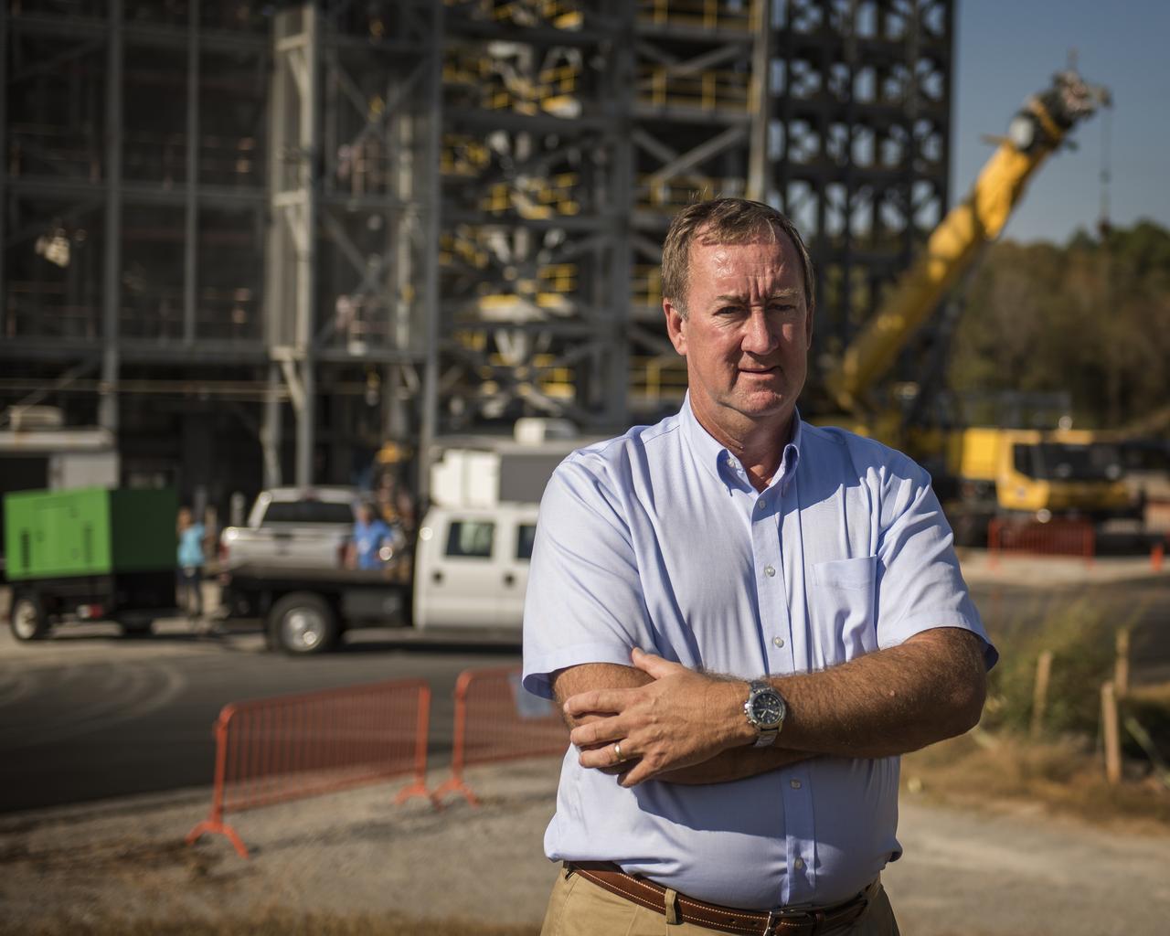
Retiring Marshall Space Flight Center Director Todd May on top of test stand 4693 in MSFC's west test area with MSFC in the background
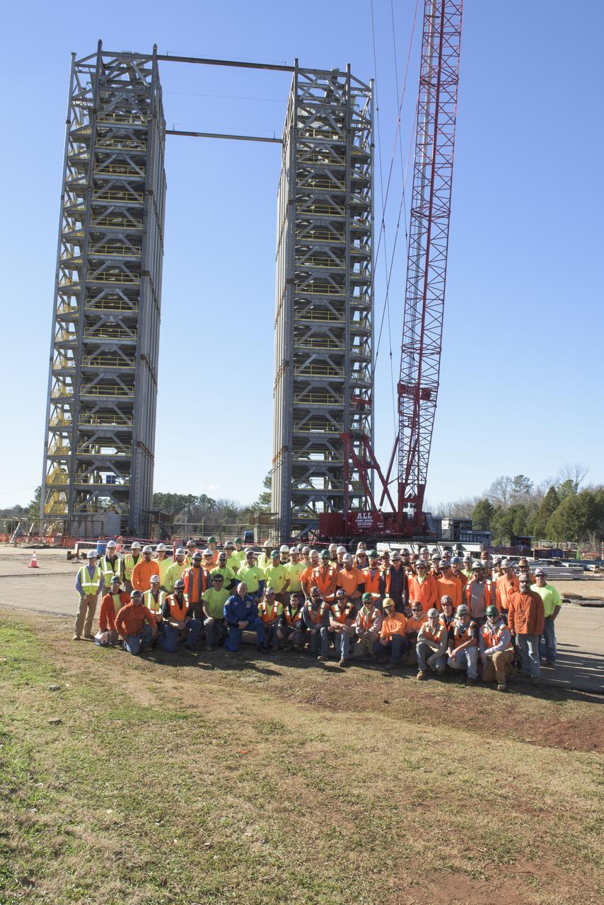
NASA astronaut Butch Wilmore in a group photograph with construction workers building SLS test stand 4693 in the West test area of the Marshall Space Flight Center

As the sun sets across the Alabama country side, engineers at Marshall's Test Stand 116 perform an endurance test on a 750K experimental engine.
A sub-scale Vernier hydrogen engine firing at Marshall's Test Stand 116. The Vernier engine is being tested for sub-orbital flight use.
This photodepicts a 15 K Fastrac motor ignition test performed at Marshall Test Stand-116. The Fastrac motor is an alternative low-cost engine which is being developed and tested at Marshall. This engine was to eventually be used on an X-34 launchvehicle. The X-34 program was cancelled in 2001.
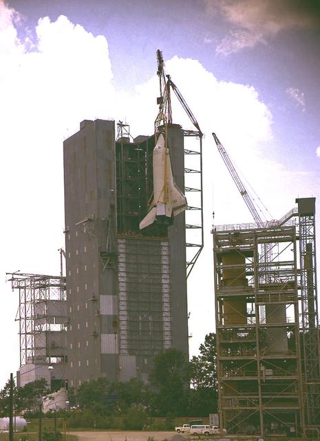
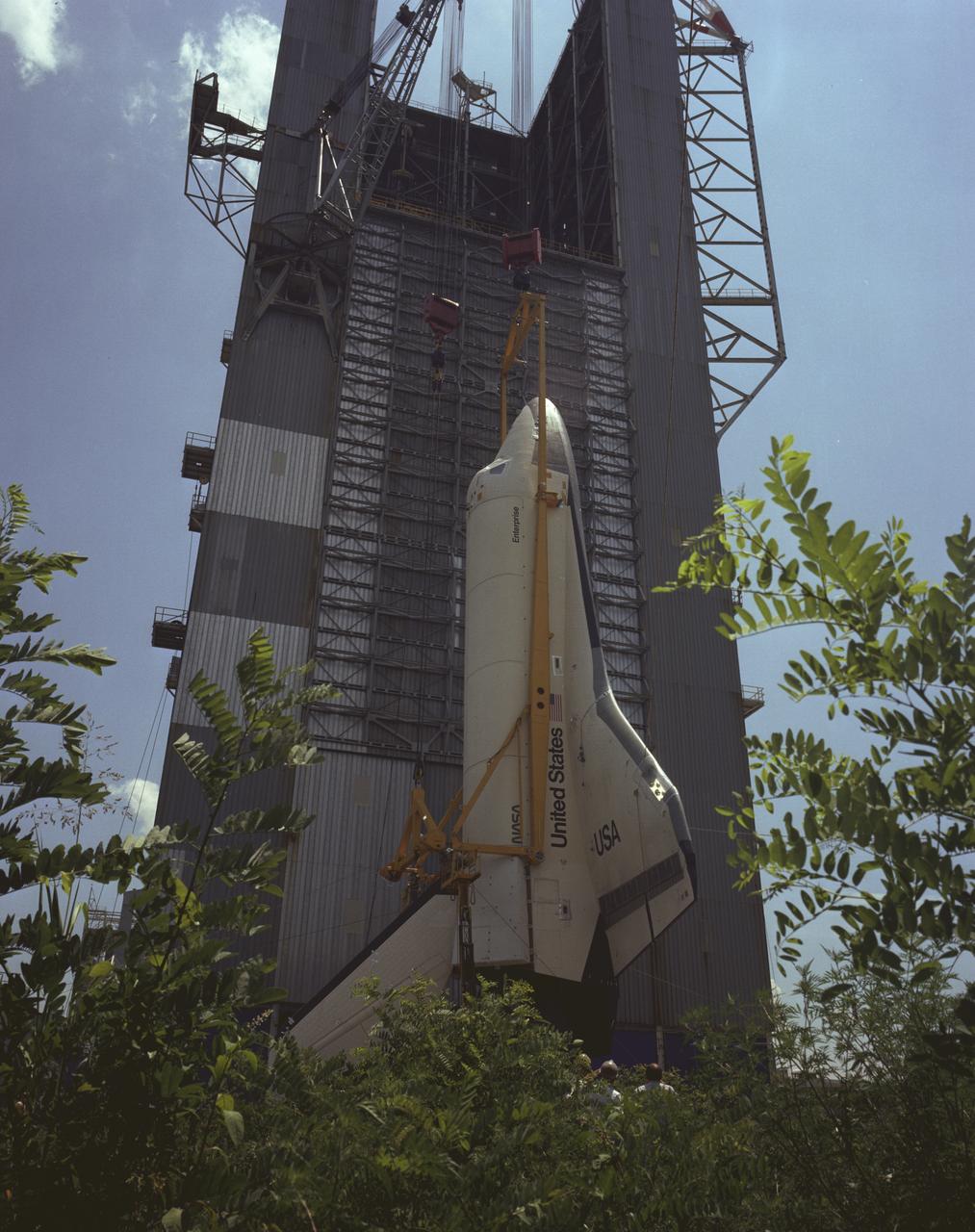
In preparation for the Mated Vertical Ground Vibration Test (MVGVT), the Shuttle Orbiter Enterprise is being erected just prior to installation into the Marshall Space Flight Center's Dynamic Test Stand for testing. This particular view is from Test Stand 500.
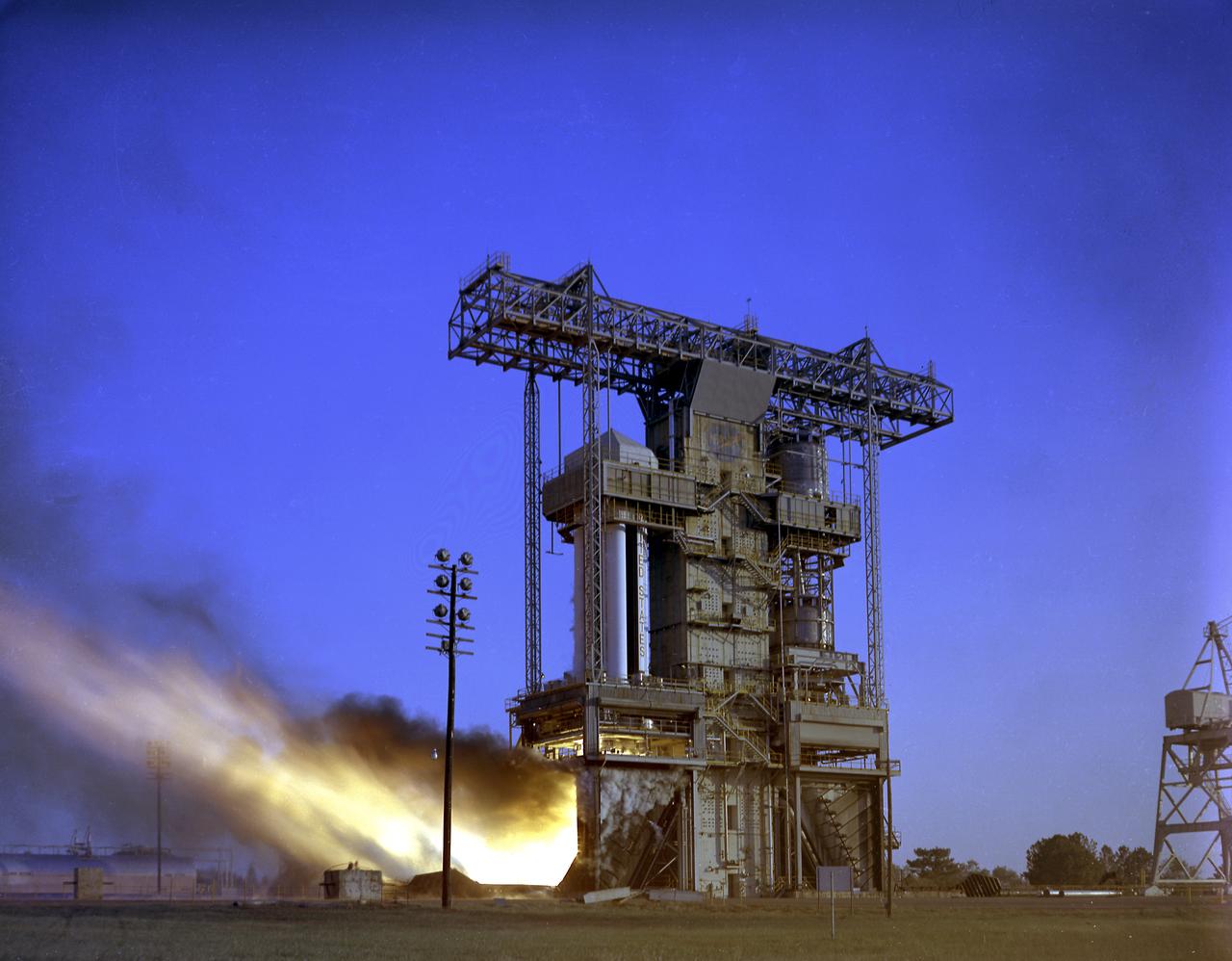
Test firing of the Saturn I S-I Stage (S-1-10) at the Marshall Space Flight Center. This test stand was originally constructed in 1951 and sometimes called the Redstone or T tower. In l961, the test stand was modified to permit static firing of the S-I/S-IB stages, which produced a total thrust of 1,600,000 pounds. The name of the stand was then changed to the S-IB Static Test Stand.
750 K motor test firing at Marshall's Test Stand 116 developing 650 pounds of thrust. The motor was tested for the Air Force Expendable Launch Vehicle (ELV) project.
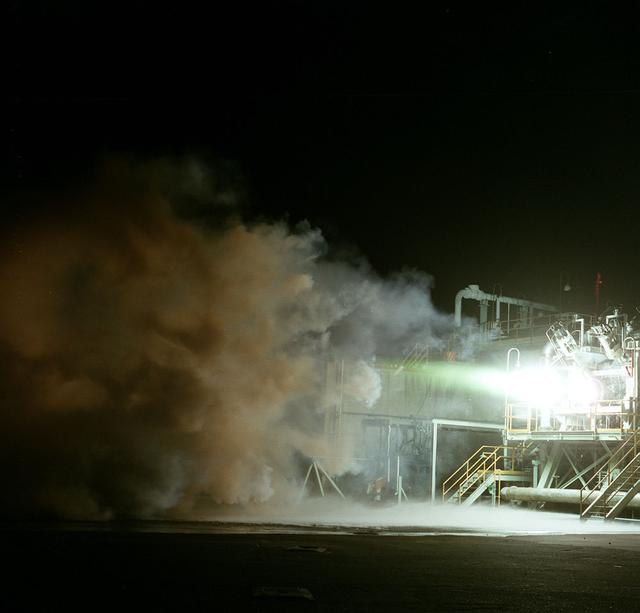
750 K motor test firing at Marshall's Test Stand 116 developing 650 pounds of thrust. The motor was tested for the Air Force Expendable Launch Vehicle (ELV) project.
A 40 K Fastrac II duration test performed at Marshall Test Stand 116. The purpose of this test was to gauge the length of time between contact of TEA (Triethylenealuminum) and LOX (liquid oxygen) as an ignitor for the Fastrac engine.
BALL AEROSPACE AND NASA ENGINEERS & TECHNICIANS INSTALL MIRRORS ON THE ROTATABLE CRYOGENIC OPTICAL TEST STAND IN MARSHALL SPACE FLIGHT CENTER’S XRCF CLEAN ROOM
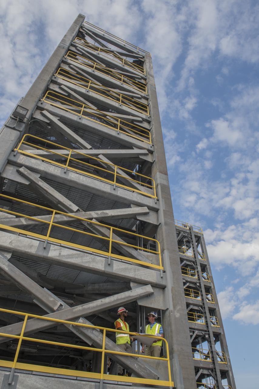
AS THE END OF CONSTRUCTION ON TEST STAND 4697, THE LIQUID OXYGEN TANK TEST STAND AT MARSHALL SPACE FLIGHT CENTER, PROJECT ENGINEERS PHIL HENDRIX, FROM MSFC, AND CURTNEY WALTERS FROM THE U.S. CORP OF ENGINEERS, STUDY PLANS AND PROGRESS.
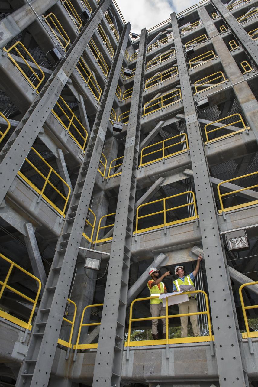
AS THE END OF CONSTRUCTION ON TEST STAND 4697, THE LIQUID OXYGEN TANK TEST STAND AT MARSHALL SPACE FLIGHT CENTER, PROJECT ENGINEERS PHIL HENDRIX, FROM MSFC, AND CURTNEY WALTERS FROM THE U.S. CORP OF ENGINEERS, STUDY PLANS AND PROGRESS.
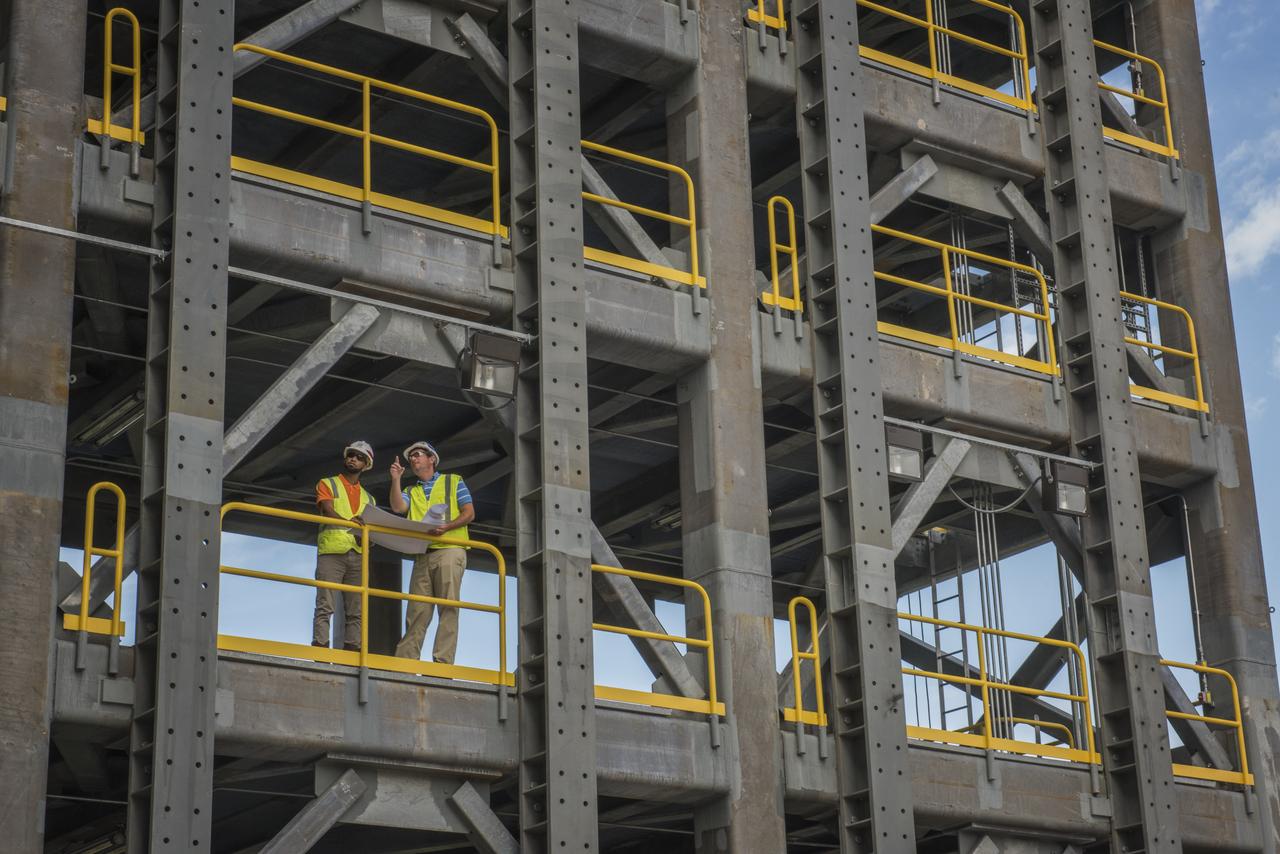
AS THE END OF CONSTRUCTION ON TEST STAND 4697, THE LIQUID OXYGEN TANK TEST STAND AT MARSHALL SPACE FLIGHT CENTER, PROJECT ENGINEERS PHIL HENDRIX, FROM MSFC, AND CURTNEY WALTERS FROM THE U.S. CORP OF ENGINEERS, STUDY PLANS AND PROGRESS.
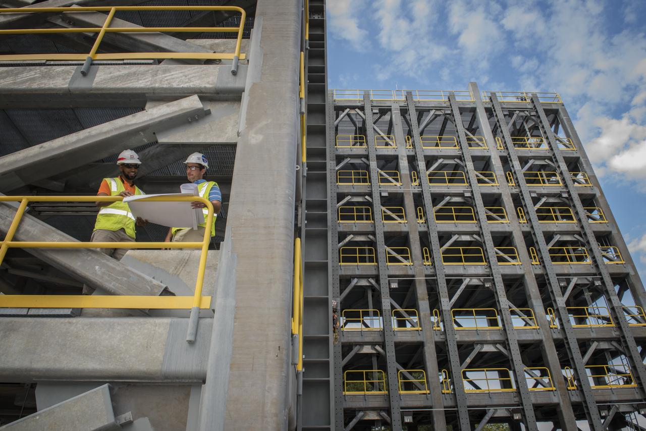
AS THE END OF CONSTRUCTION ON TEST STAND 4697, THE LIQUID OXYGEN TANK TEST STAND AT MARSHALL SPACE FLIGHT CENTER, PROJECT ENGINEERS PHIL HENDRIX, FROM MSFC, AND CURTNEY WALTERS FROM THE U.S. CORP OF ENGINEERS, STUDY PLANS AND PROGRESS.
AS THE END OF CONSTRUCTION ON TEST STAND 4697, THE LIQUID OXYGEN TANK TEST STAND AT MARSHALL SPACE FLIGHT CENTER, PROJECT ENGINEERS PHIL HENDRIX, FROM MSFC, AND CURTNEY WALTERS FROM THE U.S. CORP OF ENGINEERS, STUDY PLANS AND PROGRESS.
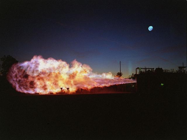
This shot offers a bird's eye-view of a Fastrac II engine duration test at Marshall's Test Stand 116. The Fastrac II engine was designed as a part of the low cost X-34 Reusable Launch Vehicle (RLV). The purpose for these tests was to test the different types of metal alloys in the nozzle. Beside the engine were six additional nozzels which spray a continuous stream of water onto the test stand to reduce damage to the test stand and the engines. The X-34 program was cancelled in 2001.
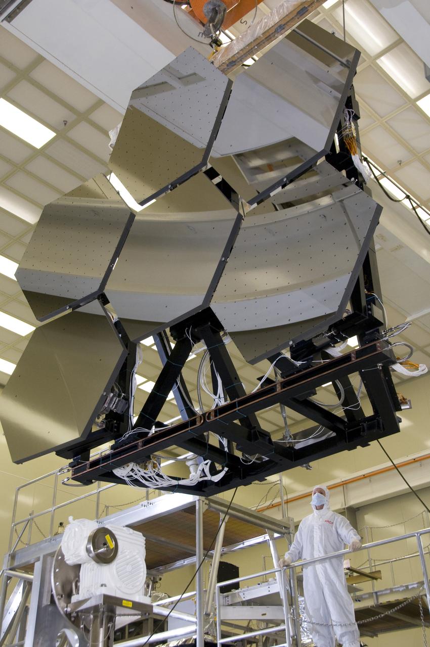
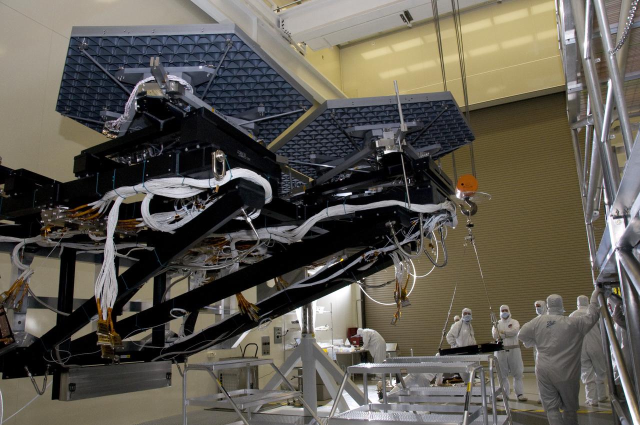
ERNIE WRIGHT, TEST DIRECTOR, MONITORS MOVE OF TEST STAND WITH SIX JWST (JAMES WEBB SPACE TELESCOPE) PRIMARY MIRROR SEGMENT ASSEMBLIES AT MARSHALL'S X-RAY AND CRYOGENIC FACILITY.
24 inch Hybrid motor test firing at Marshall's Test Stand 500. Liquid/gas are mixed with solid propellents to investigate materials, propellents, and nozzle stability characteristics.
24 inch Hybrid motor test firing at Marshall's Test Stand 500. Liquid/gas are mixed with solid propellents to investigate materials, propellents, and nozzle stability characteristics.
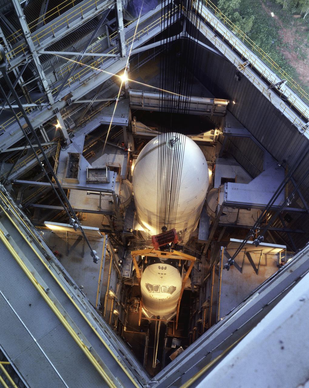
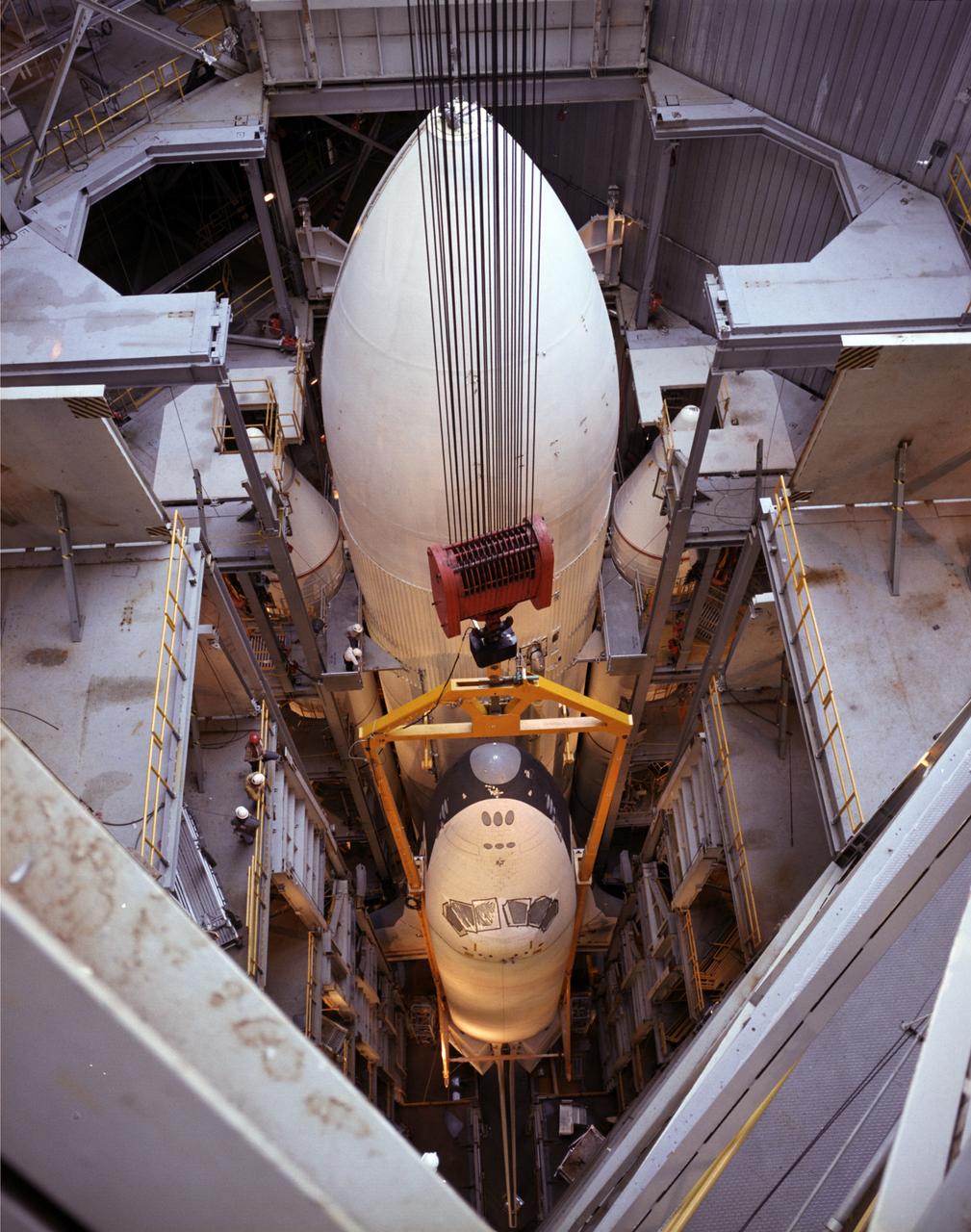
This photo is of the removal of the Orbiter Enterprise from the Marshall Space Flight Center's Dynamic Test Stand after its first Mated Vertical Ground Vibration Test (MVGVT).
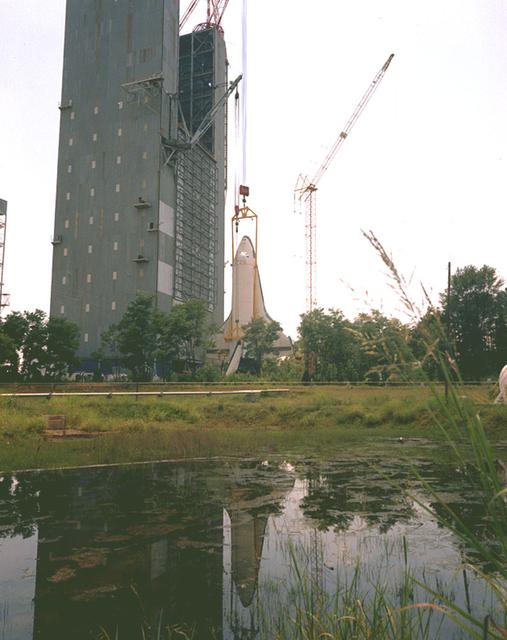
Shown here is the Shuttle Orbiter Enterprise being erected, just prior to installation into the Marshall Space Flight Center (MSFC) Dynamic Test Stand, for a Mated Vertical Ground Vibration Test (MVGVT).
This is a photo of the removal of the Orbiter Enterprise from the Marshall Space Flight Center Dynamic Test Stand after its first Mated Vertical Ground Vibration Test (MVGVT).
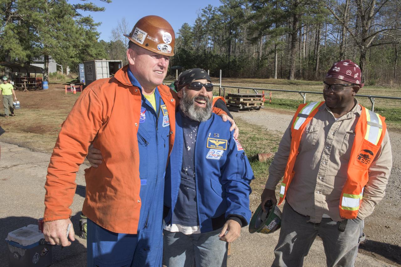
NASA astronaut Butch Wilmore exchanges jacket and hard hat with one of the construction workers building SLS test stand 4693 in the West test area of the Marshall Space Flight Center
This photograph was taken of the Orbiter Enterprise installation, in its liftoff configuration, into the Marshall Space Flight Center Dynamic Test Stand for a Mated Vertical Ground Vibration Test (MVGVT).
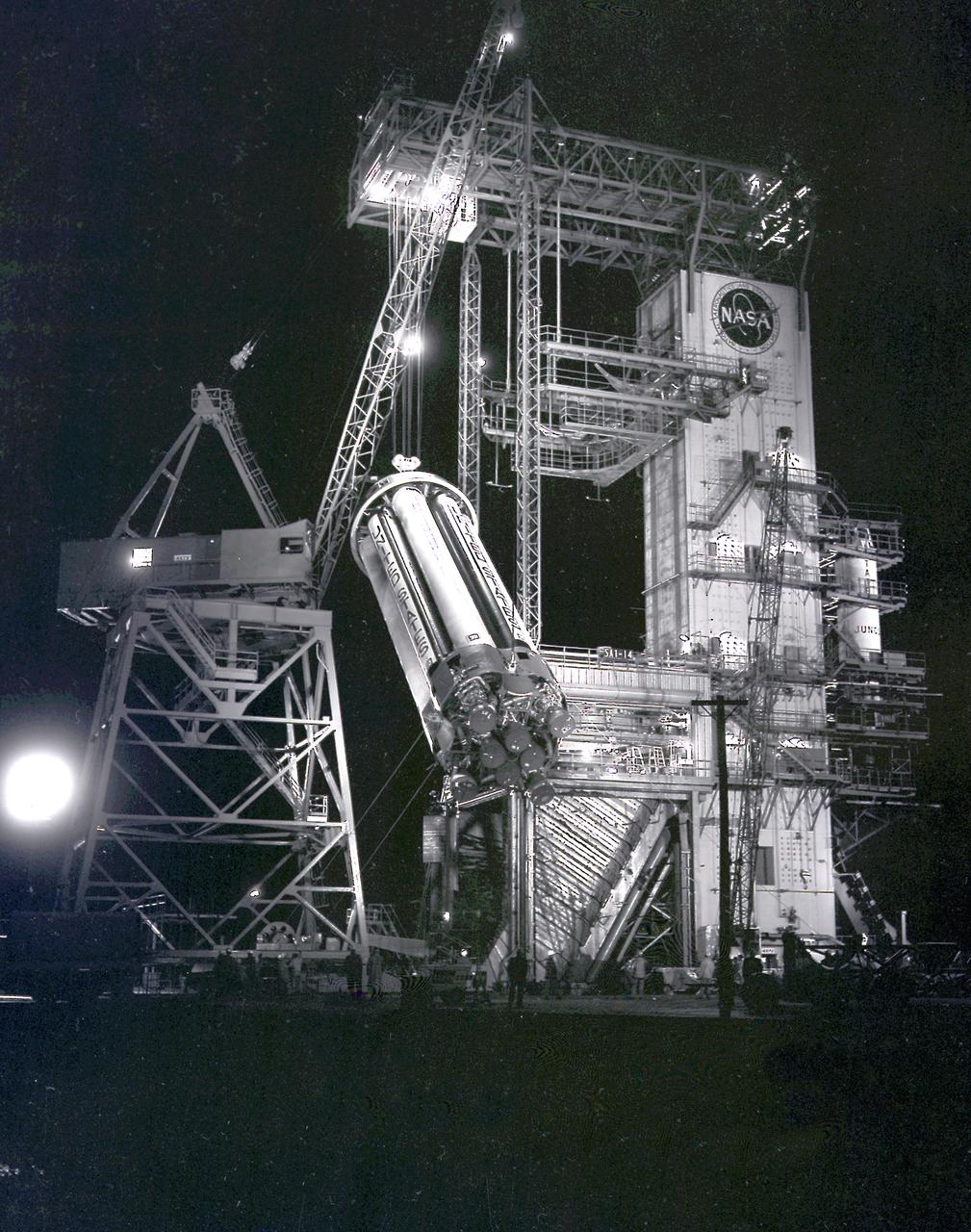
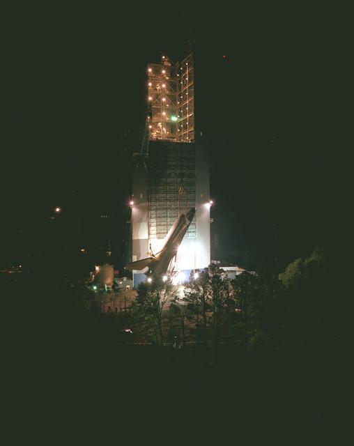
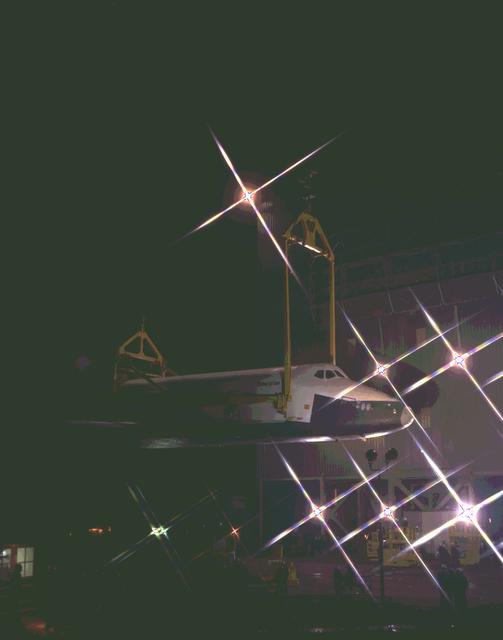
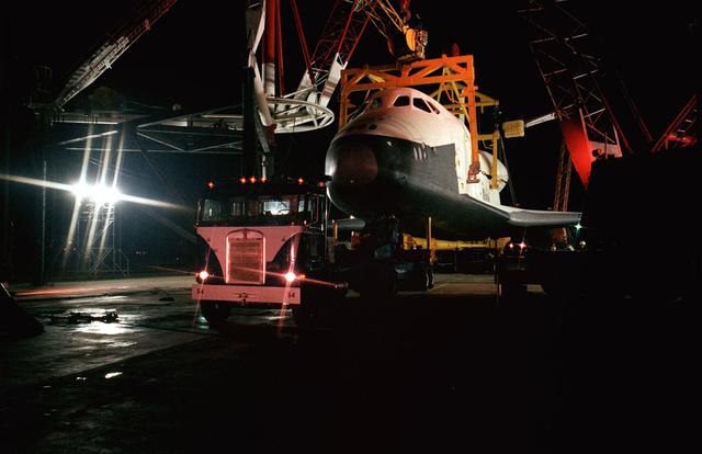
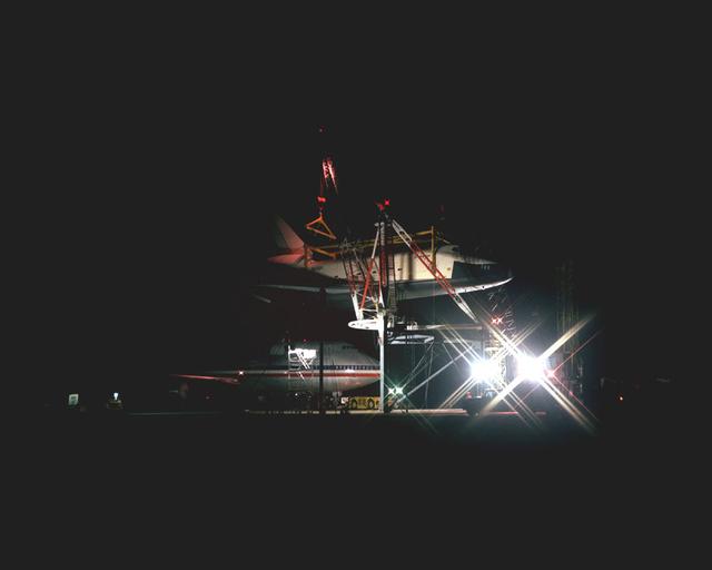
This night photograph depicts the SA-1 booster (Saturn I S-I stage) being removed from the test stand after the first flight qualification testing at the Marshall Space Flight Center (MSFC).
This photograph was taken at the Orbiter Enterprise installation, in its liftoff configuration, into the Marshall Space Flight Center Dynamic Test Stand for a Mated Vertical Ground Vibration Test (MVGVT).
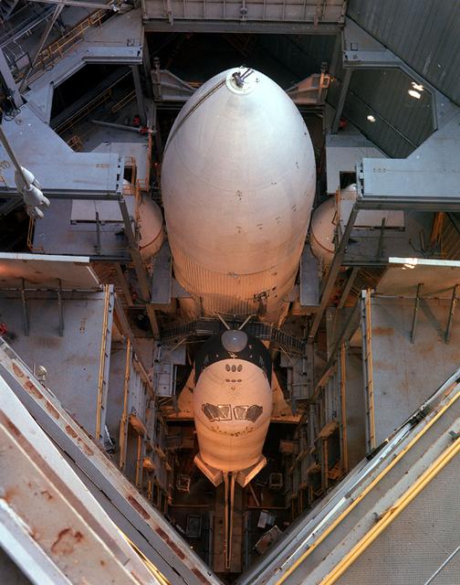
In its mated liftoff configuration of External Tank (ET) and Solid Rocket Boosters (SRB's), the Orbiter Enterprise (OV101) is pictured in the Marshall Space Flight Center Dynamic Test Stand for a Mated Vertical Ground Vibration Test (MVGVT).
This photo depicts the removal of the Orbiter Enterprise from The Marshall Space Flight Center's Dynamic Test Stand after its first Mated Vertical Ground Vibration Test (MVGVT).
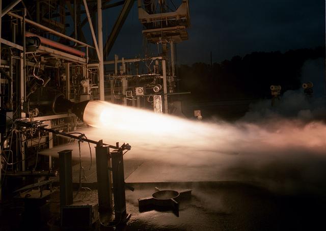
This is a photo of a 40 K Test of a single thrust cell of the Fastrac engine for the X-33, an alternate light-weight launch vehicle, at Marshall Test Stand-116. The X-33 program was cancelled in 2001.
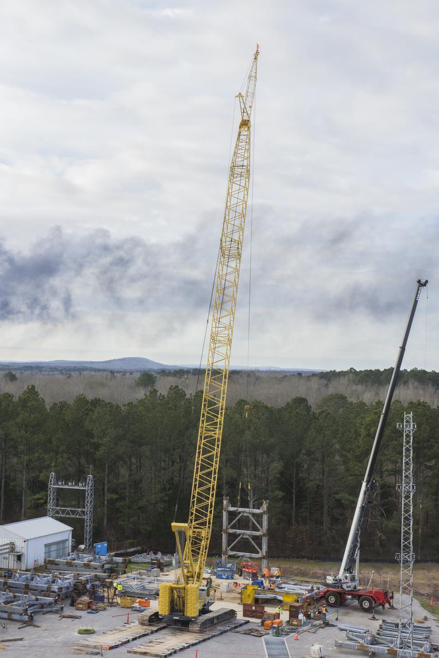
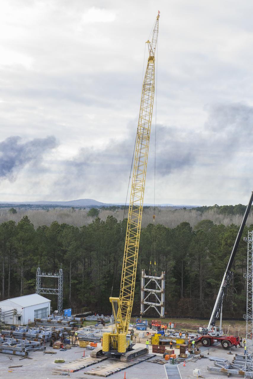
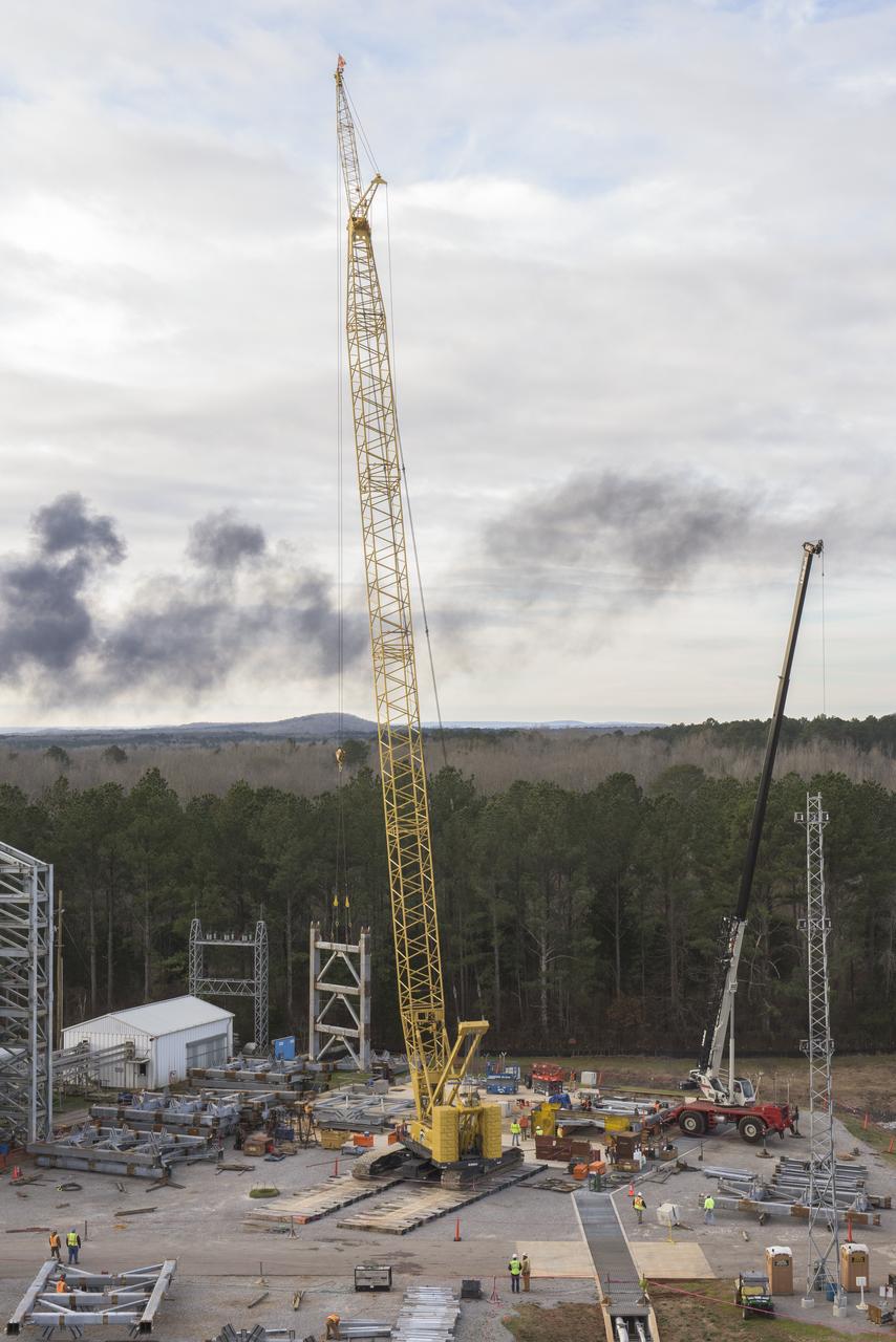
A CRANE MOVES THE FIRST STEEL TIER TO BE BOLTED INTO PLACE ON JAN. 6, FOR WELDING OF A SECOND NEW STRUCTURAL TEST STAND AT NASA'S MARSHALL SPACE FLIGHT CENTER IN HUNTSVILLE, ALABAMA -- CRITICAL TO DEVELOPMENT OF NASA'S SPACE LAUNCH SYSTEM. WHEN COMPLETED THIS SUMMER, THE 85-FOOT-TALL TEST STAND 4697 WILL USE HYDRAULIC CYLINDERS TO SUBJECT THE LIQUID OXYGEN TANK AND HARDWARE OF THE MASSIVE SLS CORE STAGE TO THE SAME LOADS AND STRESSES IT WILL ENDURE DURING A LAUNCH. THE STAND IS RISING IN MARSHALL'S WEST TEST AREA, WHERE WORK IS ALSO UNDERWAY ON THE 215-FOOT-TALL TOWERS OF TEST STAND 4693, WHICH WILL CONDUCT SIMILAR STRUCTURAL TESTS ON THE SLS CORE STAGE'S LIQUID HYDROGEN TANK. SLS, THE MOST POWERFUL ROCKET EVER BUILT, WILL CARRY ASTRONAUTS IN NASA'S ORION SPACECRAFT ON DEEP SPACE MISSIONS, INCLUDING THE JOURNEY TO MARS.
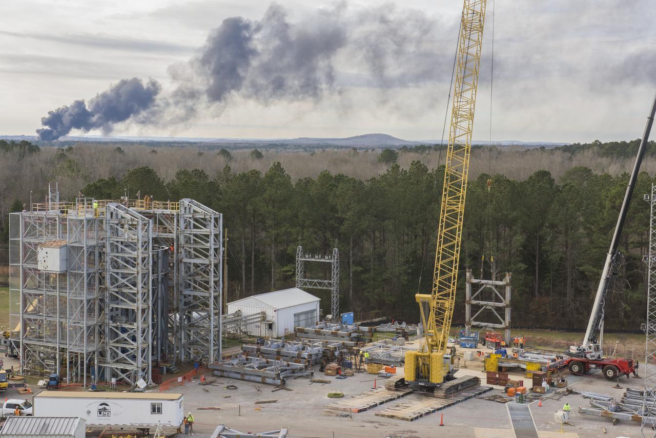
A CRANE MOVES THE FIRST STEEL TIER TO BE BOLTED INTO PLACE ON JAN. 6, FOR WELDING OF A SECOND NEW STRUCTURAL TEST STAND AT NASA'S MARSHALL SPACE FLIGHT CENTER IN HUNTSVILLE, ALABAMA -- CRITICAL TO DEVELOPMENT OF NASA'S SPACE LAUNCH SYSTEM. WHEN COMPLETED THIS SUMMER, THE 85-FOOT-TALL TEST STAND 4697 WILL USE HYDRAULIC CYLINDERS TO SUBJECT THE LIQUID OXYGEN TANK AND HARDWARE OF THE MASSIVE SLS CORE STAGE TO THE SAME LOADS AND STRESSES IT WILL ENDURE DURING A LAUNCH. THE STAND IS RISING IN MARSHALL'S WEST TEST AREA, WHERE WORK IS ALSO UNDERWAY ON THE 215-FOOT-TALL TOWERS OF TEST STAND 4693, WHICH WILL CONDUCT SIMILAR STRUCTURAL TESTS ON THE SLS CORE STAGE'S LIQUID HYDROGEN TANK. SLS, THE MOST POWERFUL ROCKET EVER BUILT, WILL CARRY ASTRONAUTS IN NASA'S ORION SPACECRAFT ON DEEP SPACE MISSIONS, INCLUDING THE JOURNEY TO MARS.
A CRANE MOVES THE FIRST STEEL TIER TO BE BOLTED INTO PLACE ON JAN. 6, FOR WELDING OF A SECOND NEW STRUCTURAL TEST STAND AT NASA'S MARSHALL SPACE FLIGHT CENTER IN HUNTSVILLE, ALABAMA -- CRITICAL TO DEVELOPMENT OF NASA'S SPACE LAUNCH SYSTEM. WHEN COMPLETED THIS SUMMER, THE 85-FOOT-TALL TEST STAND 4697 WILL USE HYDRAULIC CYLINDERS TO SUBJECT THE LIQUID OXYGEN TANK AND HARDWARE OF THE MASSIVE SLS CORE STAGE TO THE SAME LOADS AND STRESSES IT WILL ENDURE DURING A LAUNCH. THE STAND IS RISING IN MARSHALL'S WEST TEST AREA, WHERE WORK IS ALSO UNDERWAY ON THE 215-FOOT-TALL TOWERS OF TEST STAND 4693, WHICH WILL CONDUCT SIMILAR STRUCTURAL TESTS ON THE SLS CORE STAGE'S LIQUID HYDROGEN TANK. SLS, THE MOST POWERFUL ROCKET EVER BUILT, WILL CARRY ASTRONAUTS IN NASA'S ORION SPACECRAFT ON DEEP SPACE MISSIONS, INCLUDING THE JOURNEY TO MARS.
A CRANE MOVES THE FIRST STEEL TIER TO BE BOLTED INTO PLACE ON JAN. 6, FOR WELDING OF A SECOND NEW STRUCTURAL TEST STAND AT NASA'S MARSHALL SPACE FLIGHT CENTER IN HUNTSVILLE, ALABAMA -- CRITICAL TO DEVELOPMENT OF NASA'S SPACE LAUNCH SYSTEM. WHEN COMPLETED THIS SUMMER, THE 85-FOOT-TALL TEST STAND 4697 WILL USE HYDRAULIC CYLINDERS TO SUBJECT THE LIQUID OXYGEN TANK AND HARDWARE OF THE MASSIVE SLS CORE STAGE TO THE SAME LOADS AND STRESSES IT WILL ENDURE DURING A LAUNCH. THE STAND IS RISING IN MARSHALL'S WEST TEST AREA, WHERE WORK IS ALSO UNDERWAY ON THE 215-FOOT-TALL TOWERS OF TEST STAND 4693, WHICH WILL CONDUCT SIMILAR STRUCTURAL TESTS ON THE SLS CORE STAGE'S LIQUID HYDROGEN TANK. SLS, THE MOST POWERFUL ROCKET EVER BUILT, WILL CARRY ASTRONAUTS IN NASA'S ORION SPACECRAFT ON DEEP SPACE MISSIONS, INCLUDING THE JOURNEY TO MARS.
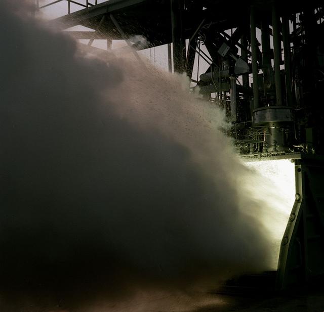
The test laboratory of the Marshall Space Flight Center (MSFC) tested the F-1 engine, the most powerful rocket engine ever fired at MSFC. The engine was tested on the newly modified Saturn IB static test stand that had been used for three years to test the Saturn I eight-engine booster, S-I (first) stage. In 1961, the test stand was modified to permit static firing of the S-I/S-IB stage and the name of the stand was then changed to the S-IB Static Test Stand. Producing a combined thrust of 7,500,000 pounds, five F-1 engines powered the S-IC (first) stage of the Saturn V vehicle for the marned lunar mission.
The test laboratory of the Marshall Space Flight Center (MSFC) tested the F-1 engine, the most powerful rocket engine ever fired at MSFC. The engine was tested on the newly modified Saturn IB Static Test Stand which had been used for three years to test the Saturn I eight-engine booster, S-I (first) stage. In 1961 the test stand was modified to permit static firing of the S-I/S-IB stage and the name of the stand was then changed to the S-IB Static Test Stand. Producing a combined thrust of 7,500,000 pounds, five F-1 engines powered the S-IC (first) stage of the Saturn V vehicle for the marned lunar mission.
MSFC, Ala. -- The Space Shuttle Orbiter simulator is hoisted into the giant dynamics test stand at NASA's Marshall Space Flight Center, Huntsville, Ala. The simulator was built at the Marshall Center for use in pathfinder activities, such as checking roadway clearances, crane capabilities and fits within structures. It is the same size, shape and weight of an actual Orbiter.
KEITH HIGGINBOTHAM, STRUCTURAL TEST LEAD FOR THE SLS SPACECRAFT PAYLOAD INTEGRATION AND EVOLUTION OFFICE, IS SHOWN BESIDE TEST STAND 4699 AT THE MARSHALL SPACE FLIGHT CENTER’S WEST TEST AREA. HIGGINBOTHAM WILL BE LEADING STRUCTURAL LOADS TESTING AT TEST STAND 4699 FOR THE CORE STAGE SIMULATER AND THE LAUNCH VEHICLE STAGE ADAPTER. THE TEST SERIES WILL ENSURE EACH STRUCTURE CAN WITHSTAND THE INCREDIBLE STRESSES OF LAUNCH.
This is a ground level view of Test Stand 500 at the east test area of the Marshall Space Flight Center. Originally constructed in 1966, Test Stand 500 is a multipurpose, dual-position test facility. The stand was utilized to test liquid hydrogen/liquid oxygen turbopumps and combustion devices for the J-2 engine. One test position has a high superstructure with lines and tankage for testing liquid hydrogen and liquid oxygen turbopumps while the other position is adaptable to pressure-fed test programs such as turbo machinery bearings or seals. The facility was modified in 1980 to support Space Shuttle main engine (SSME) bearing testing.
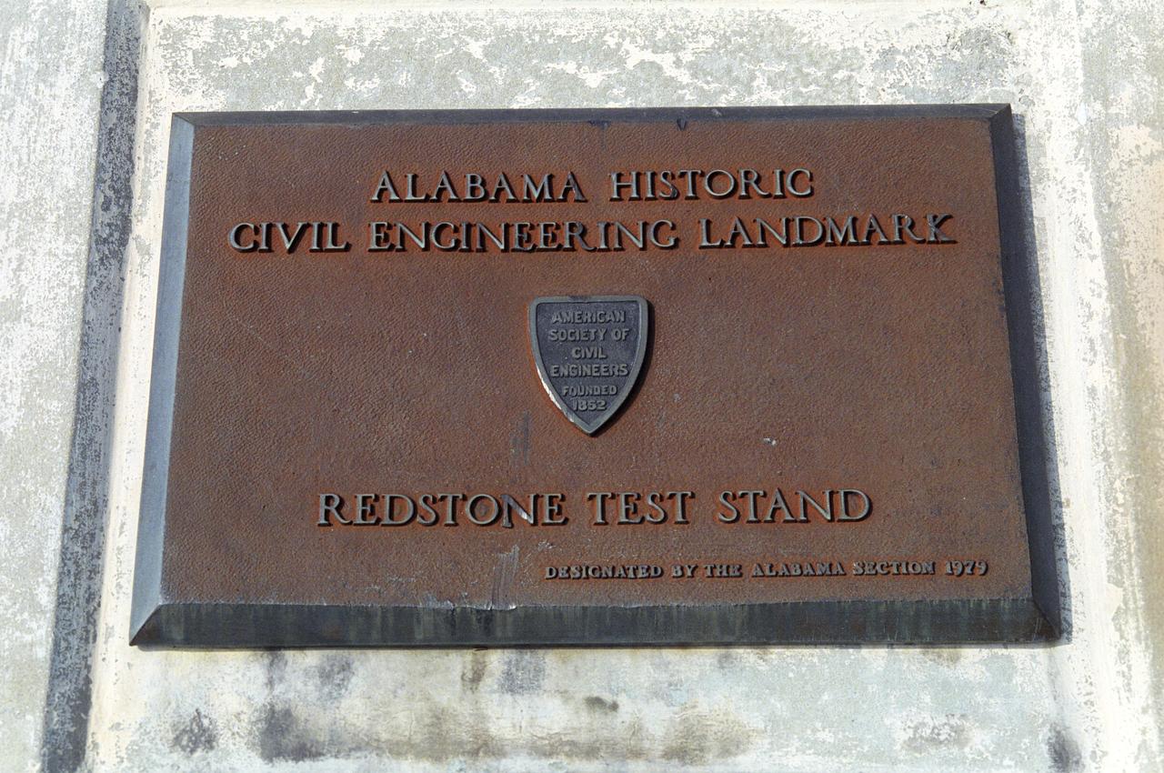
This plaque, displayed on the grounds of Marshall Space Flight Center in Huntsville, Alabama, commemorates the Redstone Test Stand as an Alabama Historic Civil Engineering Landmark. The site was desinated as such in 1979.
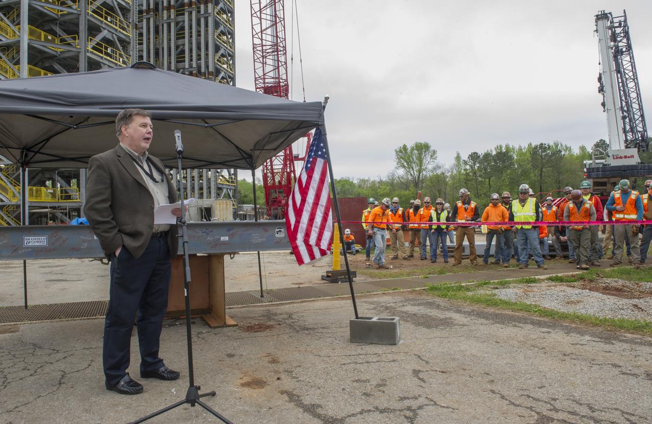
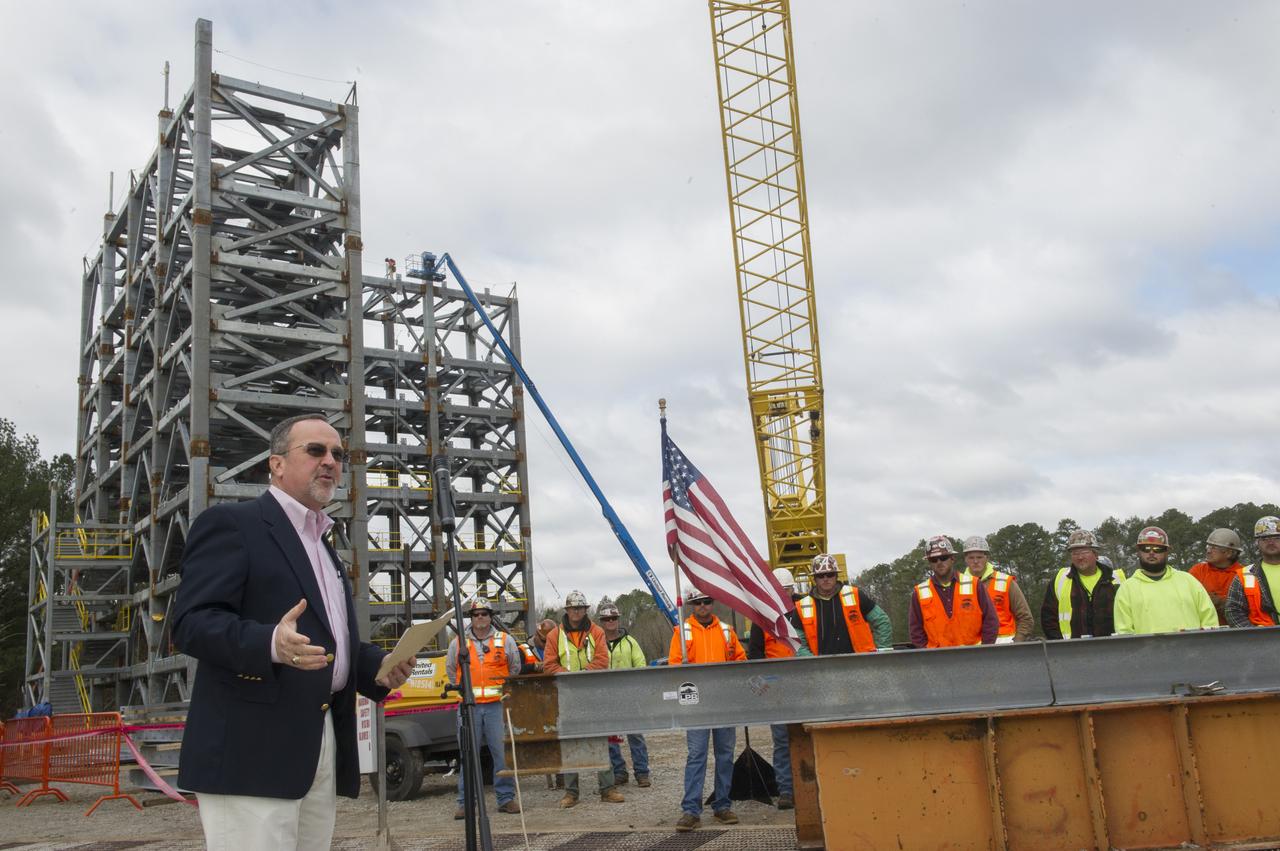
BOB DEVLIN, DEPUTY DIRECTOR OF MARSHALL'S OFFICE OF CENTER OPERATIONS, SPEAKS TO THE CROWD IN FRONT OF A STEEL BEAM DESTINED FOR TEST STAND 4693 DURING THE STRUCTURE'S TOPPING OUT CEREMONY APRIL 12.
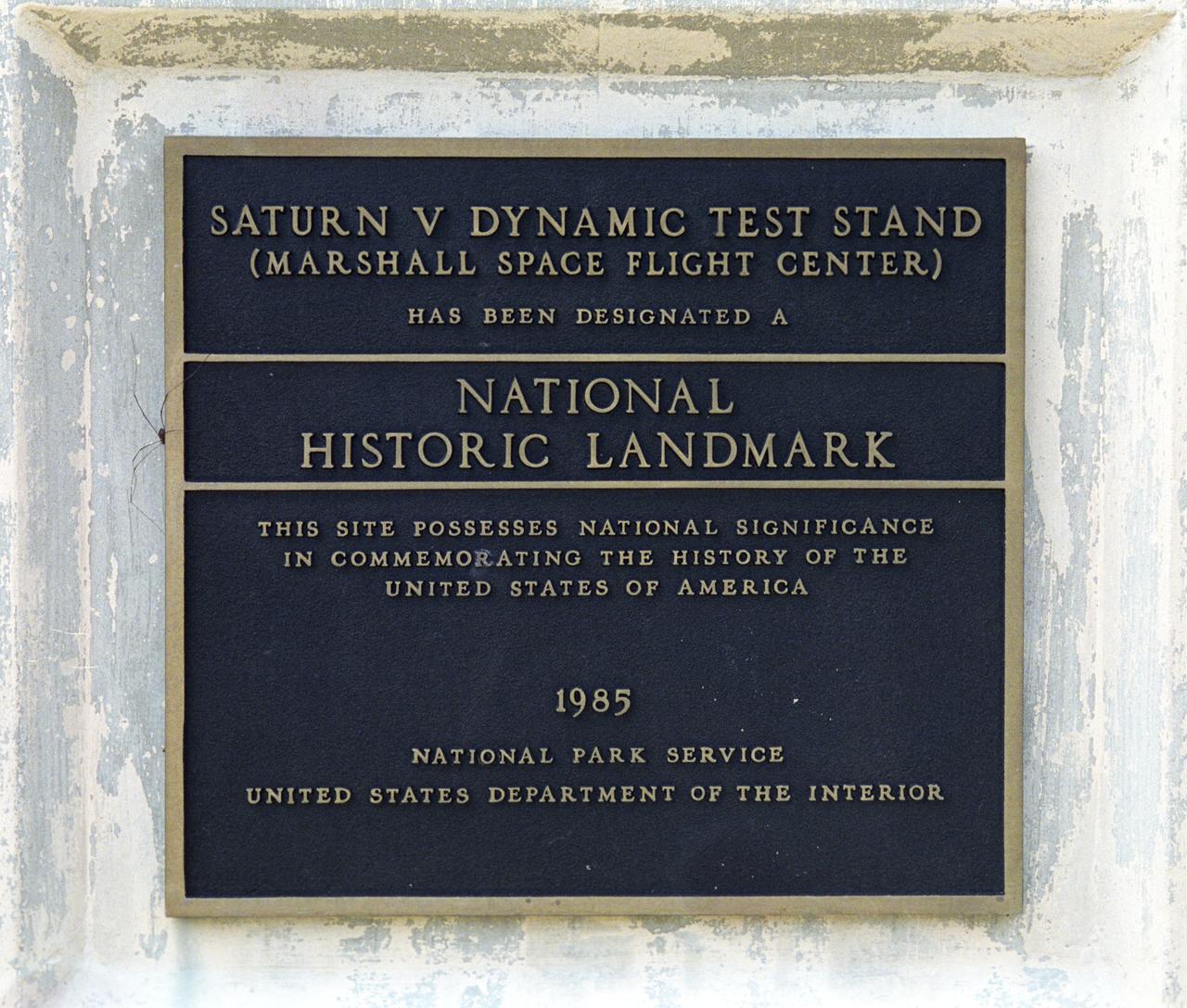
This plaque, displayed on the grounds of Marshall Space Flight Center in Huntsville, Alabama, commemorates the Saturn V Dynamic Test Stand as a National Historic Landmark. The site was designated as such in 1985 by the National Park Service of the United States Department of the Interior.
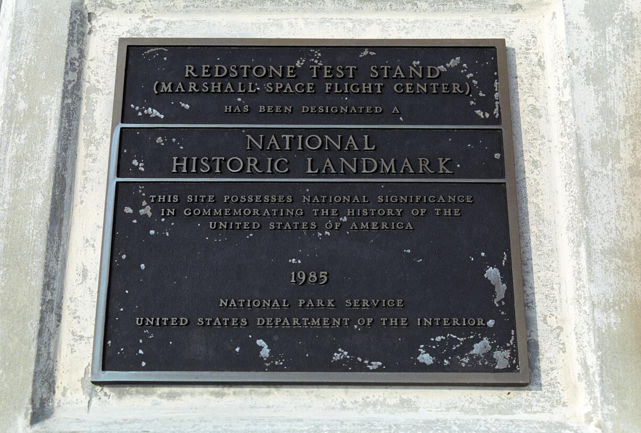
This plaque, displayed on the grounds of Marshall Space Flight Center in Huntsville, Alabama, commemorates the Redstone Test Stand as a National Historic Landmark. The site was designated as such in 1985 by the National Park Service of the United States Department of the Interior.
"YOUR WORK IS CRITICAL TO THE JOURNEY TO MARS," SAID SLS DEPUTY PROGRAM MANAGER JERRY COOK TO THE CONSTRUCTION CREW AT THE "TOP OUT" CEREMONY FOR TEST STAND 4697 AT MARSHALL.
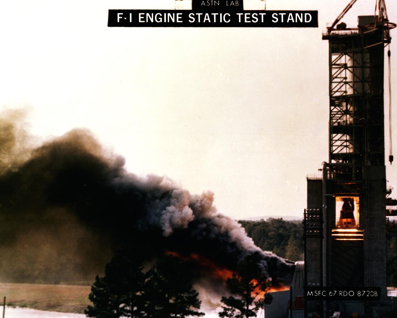
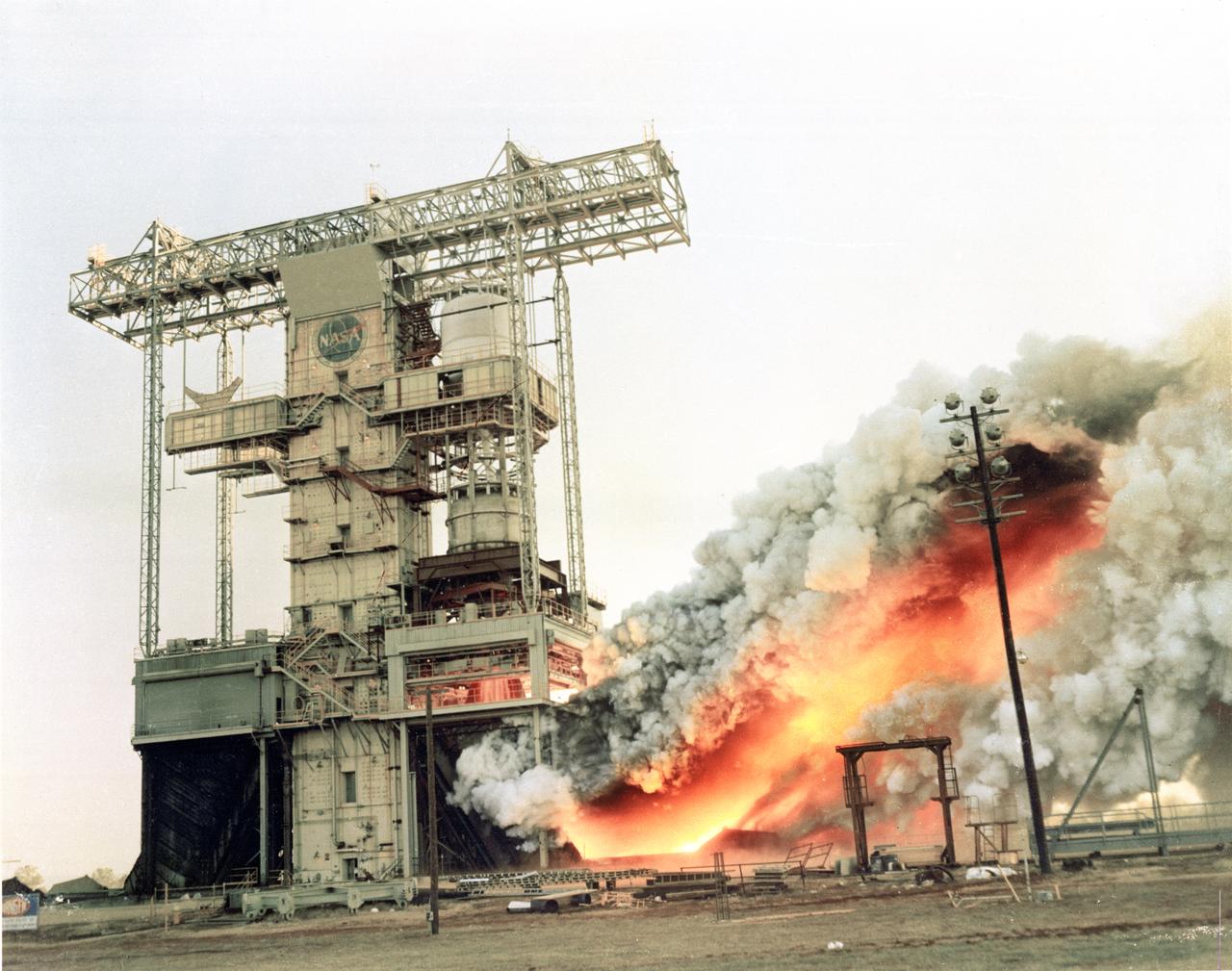
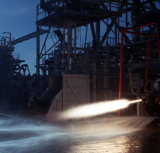
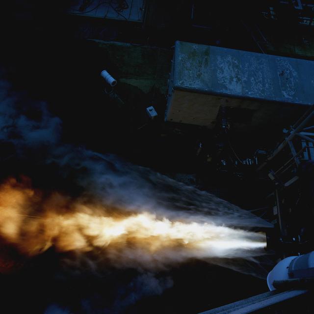
This photograph depicts the F-1 engine firing in the Marshall Space Flight Center’s F-1 Engine Static Test Stand. Construction of the S-IC Static test stand complex began in 1961 in the west test area of MSFC, and was completed in 1964. It is a vertical engine firing test stand, 239 feet in elevation and 4,600 square feet in area at the base, designed to assist in the development of the F-1 Engine. Capability is provided for static firing of 1.5 million pounds of thrust using liquid oxygen and kerosene. The foundation of the stand is keyed into the bedrock approximately 40 feet below grade.
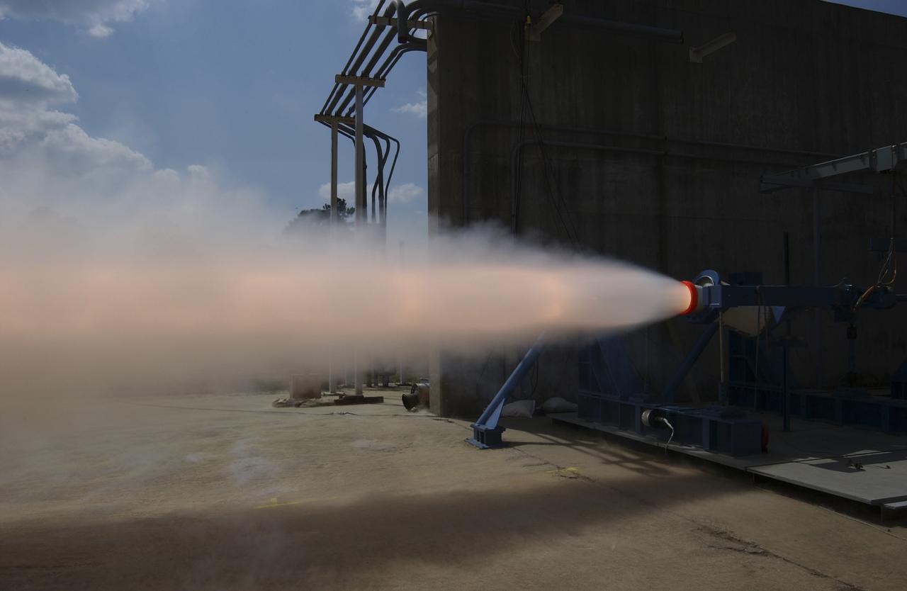
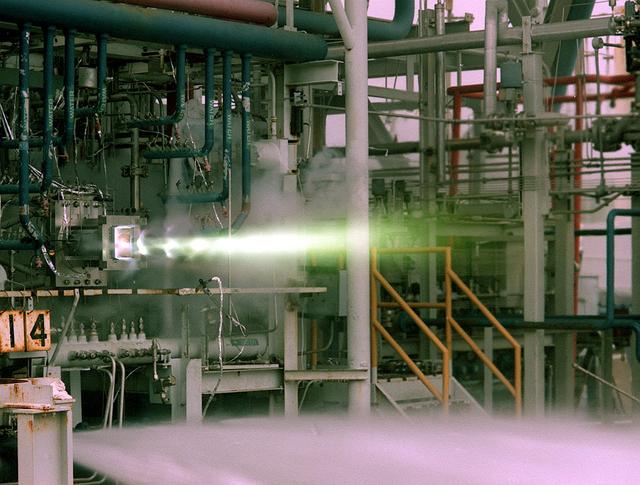
This photograph depicts a hot fire test of the Shuttle Booster Separation Motor (BSM) at the Marshall Space Flight Center (MSFC) test stand 116. The objective of the test was to test the aft heat seal in flight configuration. The function of the motor is to separate the Shuttle vehicle from the boosters that carry it into space.
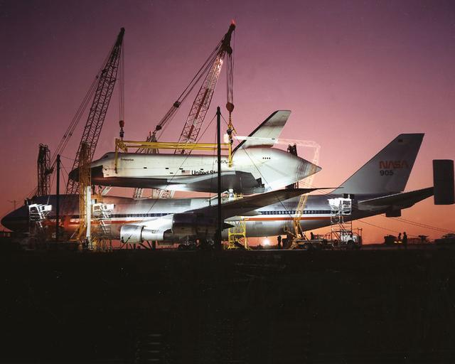
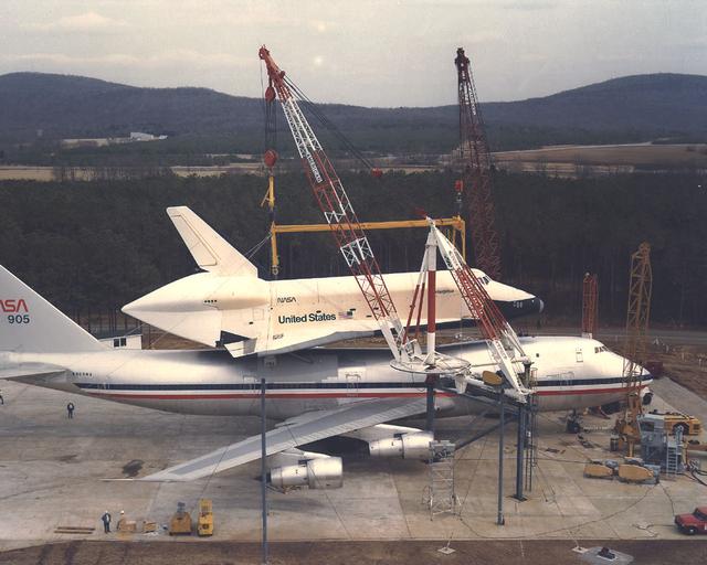
The Shuttle Orbiter Enterprise is off-loaded at Redstone Arsenal Airfield for later Mated Vertical Ground Vibration tests (MVGVT) at Marshall Space Flight Center's Dynamic Test Stand. The tests marked the first time ever that the entire shuttle complement (including orbiter, external tank, and solid rocket boosters) were mated vertically.
The Shuttle Orbiter Enterprise is off-loaded at Redstone Arsenal Airfield for later Mated Vertical Ground Vibration tests (MVGVT) at Marshall Space Flight Center's Dynamic Test Stand. The tests marked the first time ever that the entire shuttle complement including orbiter, external tank, and solid rocket boosters were vertically mated.
The Shuttle Orbiter Enterprise is off-loaded at Redstone Arsenal Airfield for later Mated Vertical Ground Vibration tests (MVGVT) at Marshall Space Flight Center's Dynamic Test Stand. The tests marked the first time ever that the entire shuttle complement (including orbiter, external tank, and solid rocket boosters) were mated vertically.
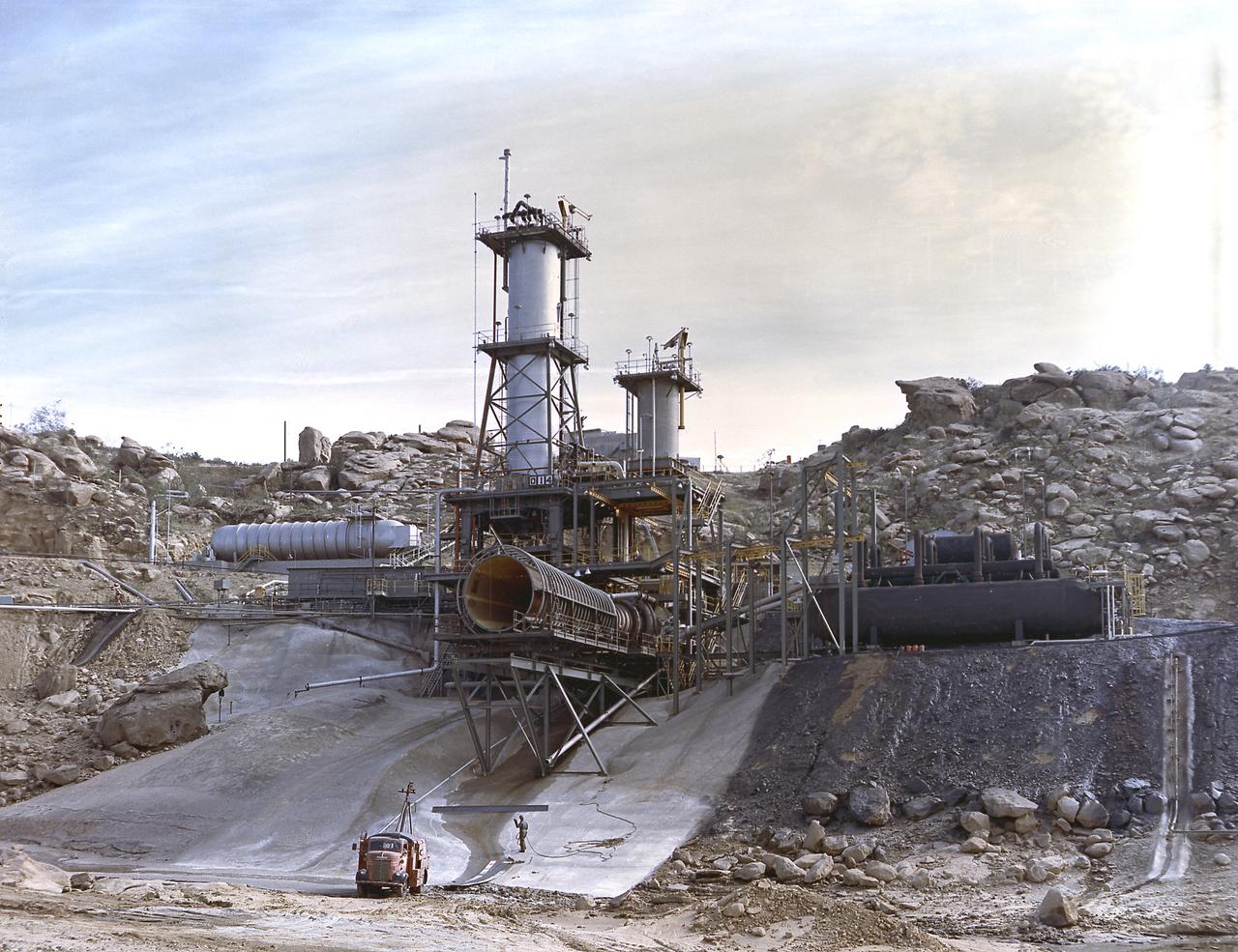
This image depicts an overall view of the vertical test stand for testing the J-2 engine at Rocketdyne's Propulsion Field Laboratory, in the Santa Susana Mountains, near Canoga Park, California. The J-2 engines were assembled and tested at Rocketdyne under the direction of the Marshall Space Flight Center.
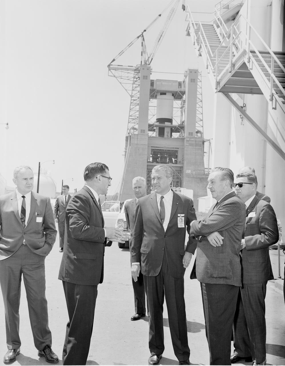
Walt Disney toured the West Test Area during his visit to the Marshall Space Flight Center on April 13, 1965. The three in center foreground are Karl Heimburg, Director, Test Division; Dr. von Braun, Director, MSFC; and Walt Disney. The Dynamic Test Stand with the S-1C stage being installed is in the background.
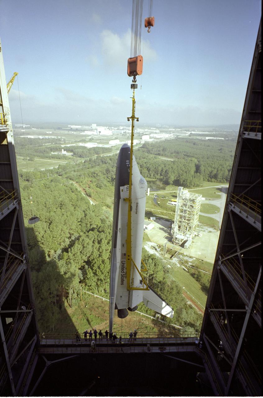
The Shuttle Orbiter Enterprise is being installed into liftoff configuration at Marshall Space Flight Center's Dynamic Test Stand for Mated Vertical Ground Vibration tests (MVGVT). The tests marked the first time ever that the entire shuttle complement (including Orbiter, external tank, and solid rocket boosters) were mated vertically.
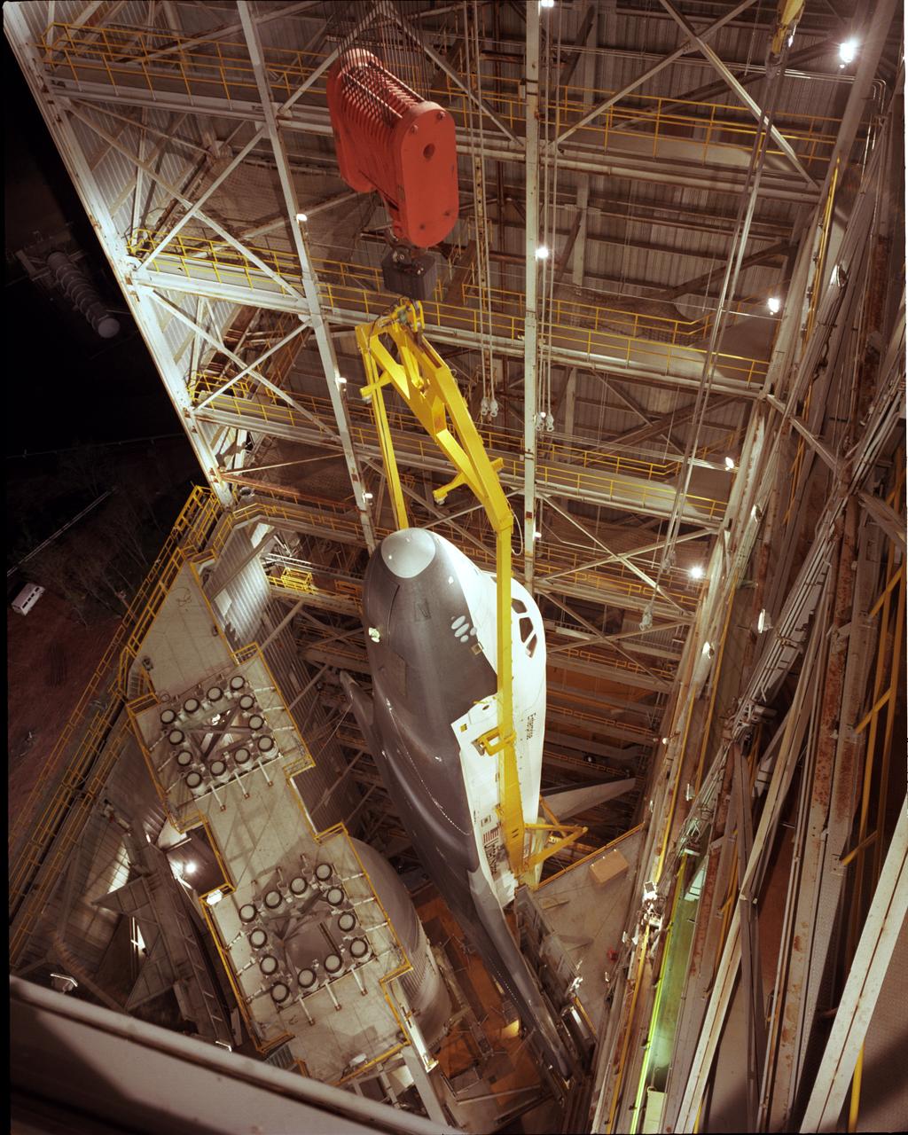
The Shuttle Orbiter Enterprise is lowered into the Dynamic Test Stand for Mated Vertical Ground Vibration tests (MVGVT) at the Marshall Space Flight Center. The tests marked the first time ever that the entire shuttle complement (including Orbiter, external tank, and solid rocket boosters) were mated vertically.
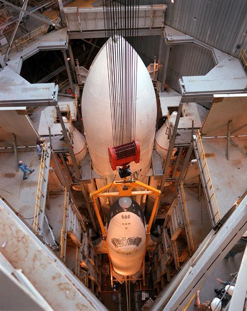
The Shuttle Orbiter Enterprise inside of Marshall Space Flight Center's Dynamic Test Stand for Mated Vertical Ground Vibration tests (MVGVT). The tests marked the first time ever that the entire shuttle complement including Orbiter, external tank, and solid rocket boosters were vertically mated.
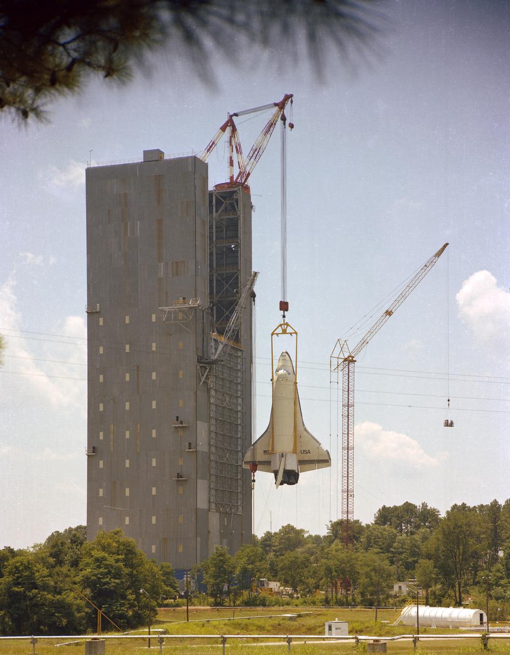
The Shuttle Orbiter Enterprise is removed from Marshall Space Flight Center's Dynamic Test Stand following its first Mated Vertical Ground Vibration test (MVGVT). The tests marked the first time ever that the entire shuttle complement (including Orbiter, external tank, and solid rocket boosters) were mated vertically.
The Shuttle Orbiter Enterprise is off-loaded Redstone Arsenal Airfield for later Mated Vertical Ground Vibration tests (MVGVT) at Marshall Space Flight Center's Dynamic Test Stand. The tests marked the first time ever that the entire shuttle complement (including orbiter, external tank, and solid rocket boosters) were mated vertically.
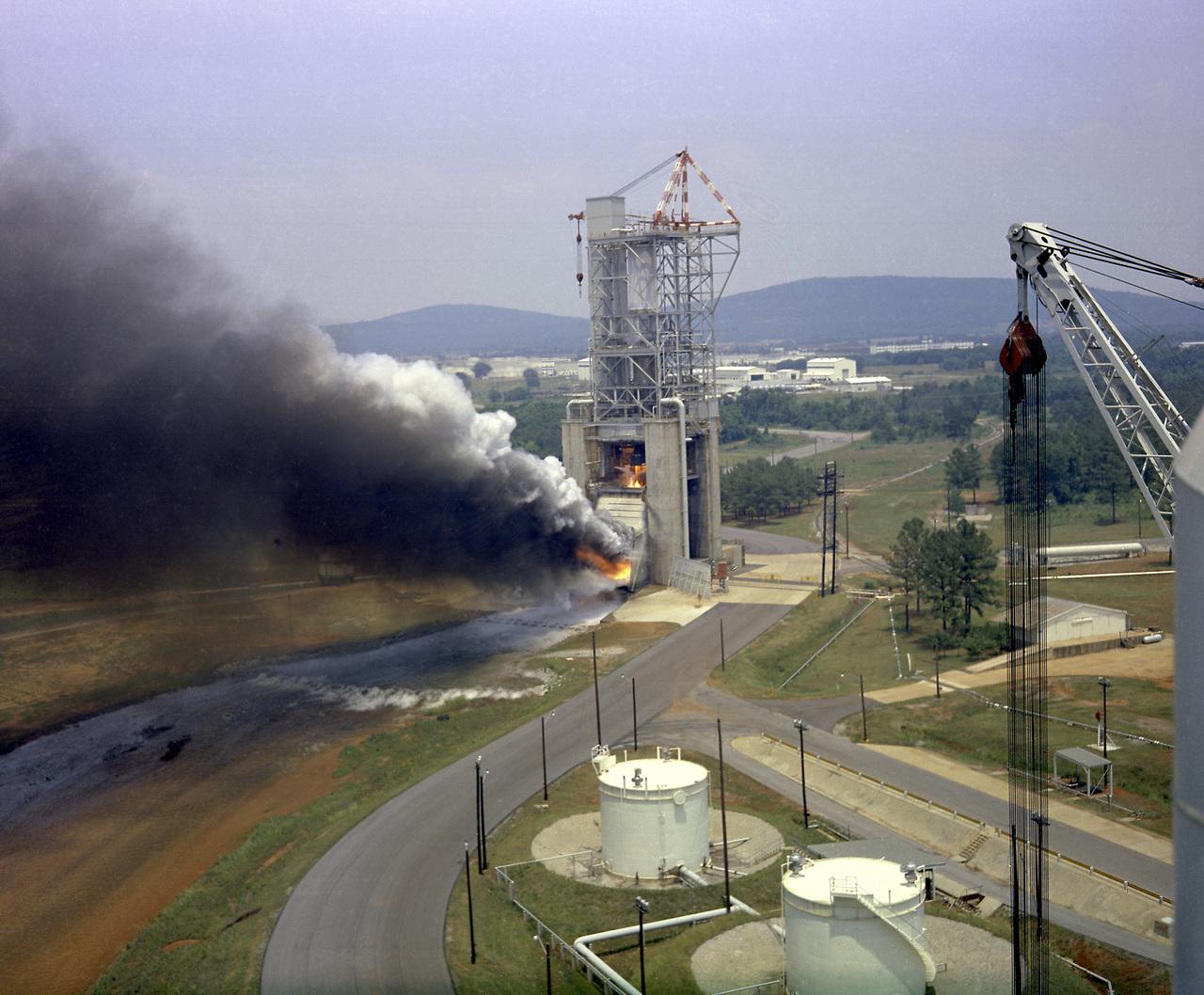
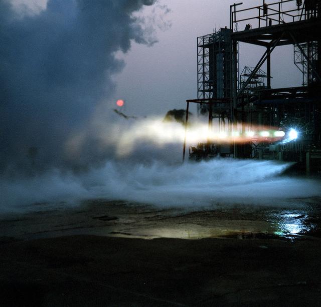
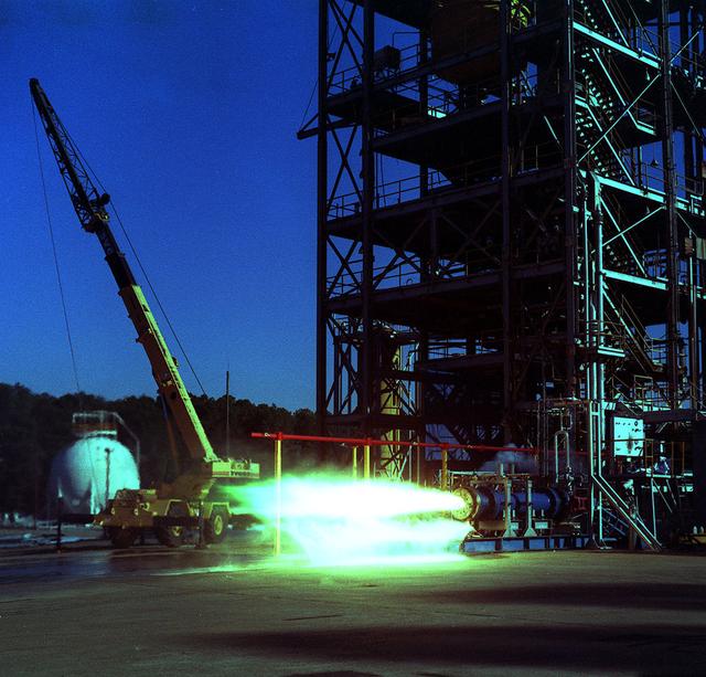
This photograph depicts a test firing of an F-1 engine at the F-1 engine test stand in the west test area of the Marshall Space Flight Center. This engine produced 1,500,000 pounds of thrust using liquid oxygen and RP-1, which is a derivative of kerosene. The F-1 engine test stand was constructed in 1963 to assist in the development of the F-1 engine.
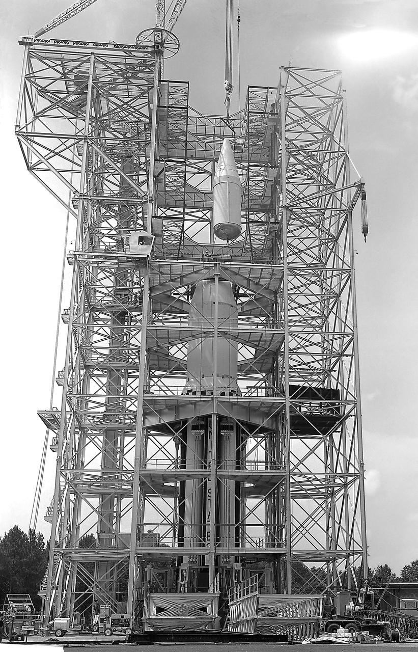
This image depicts the Saturn I launch vehicle placed in the dynamic test stand at the Marshall Space Flight Center (MSFC). A dummy booster was moved to the dynamic test stand early in June, and, for the first time, vertically mated with dummy S-I and S-IV stages. The assembled vehicle was readied for dynamic testing to investigate the integrity of the support structure.