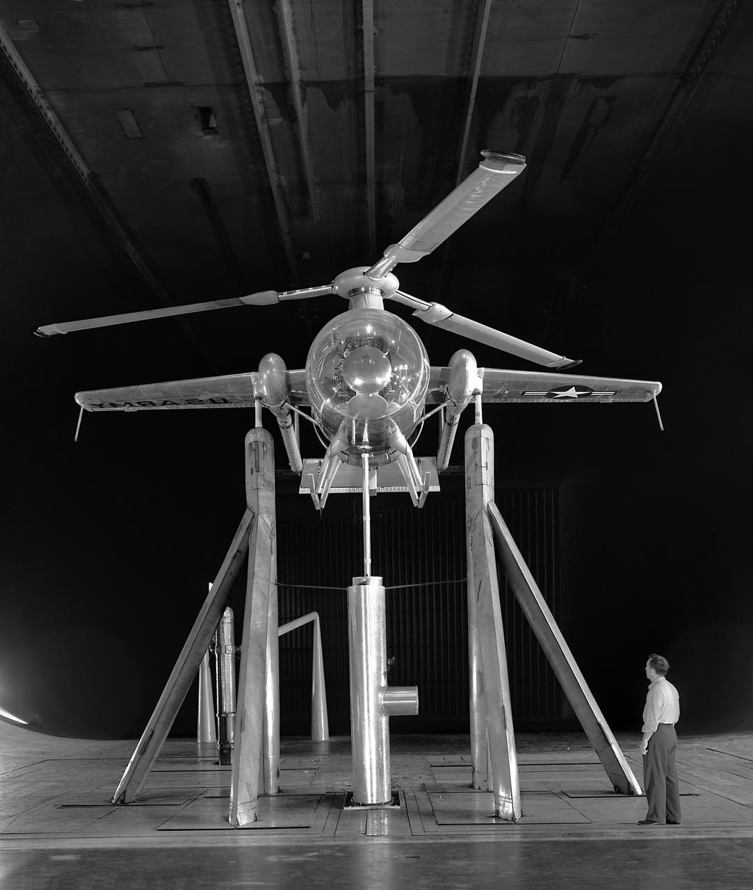
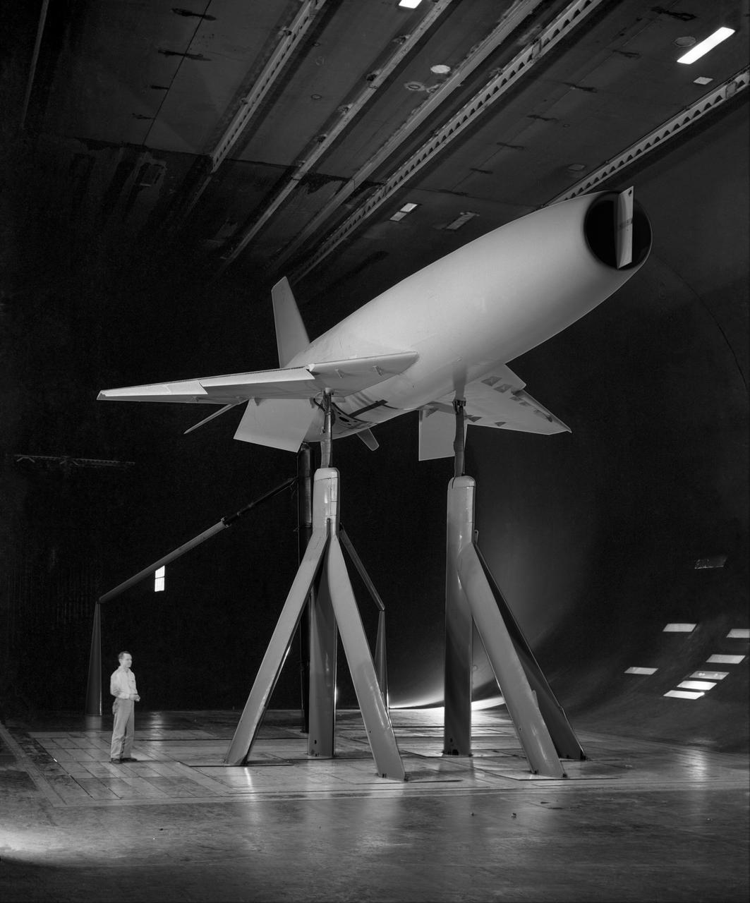
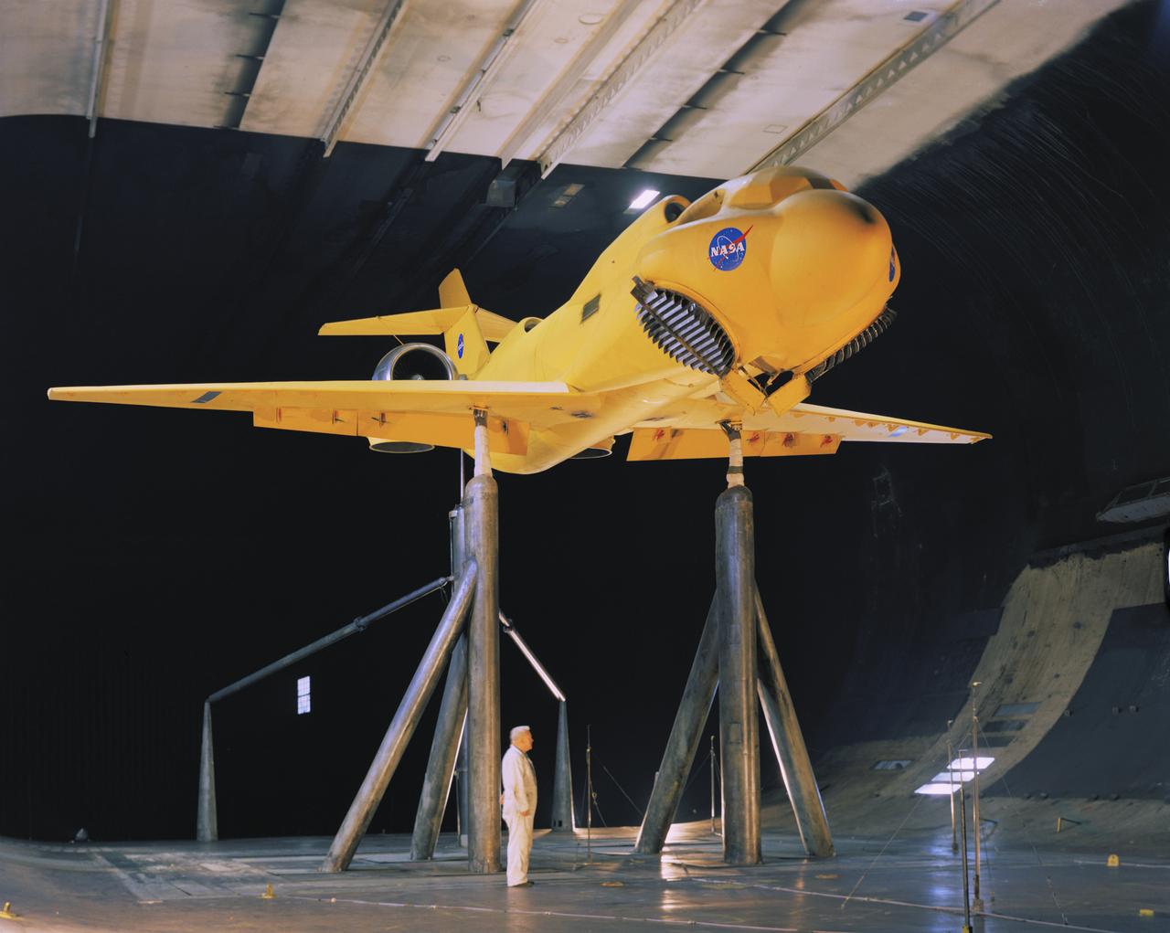
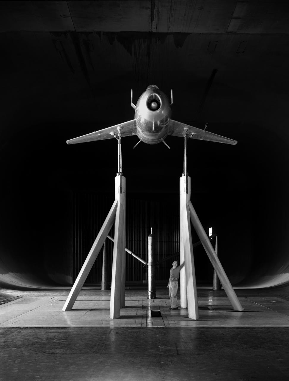
Foreword, front view of McDonnell Model XV-1 Convertiplane in the Ames 40x80 Foot Wind Tunnel. The McDonnell XV-1 was an experimental compound gyroplane developed for a joint research program between the United States Air Force and the United States Army to explore technologies to develop an aircraft that could take off and land like a helicopter but fly at faster airspeeds, similar to a conventional airplane. The XV-1 would reach a speed of 200 mph (322 km/h), faster than any previous rotorcraft, but the program was terminated due to the tip-jet noise and complexity of the technology which gave only a modest gain in performance.
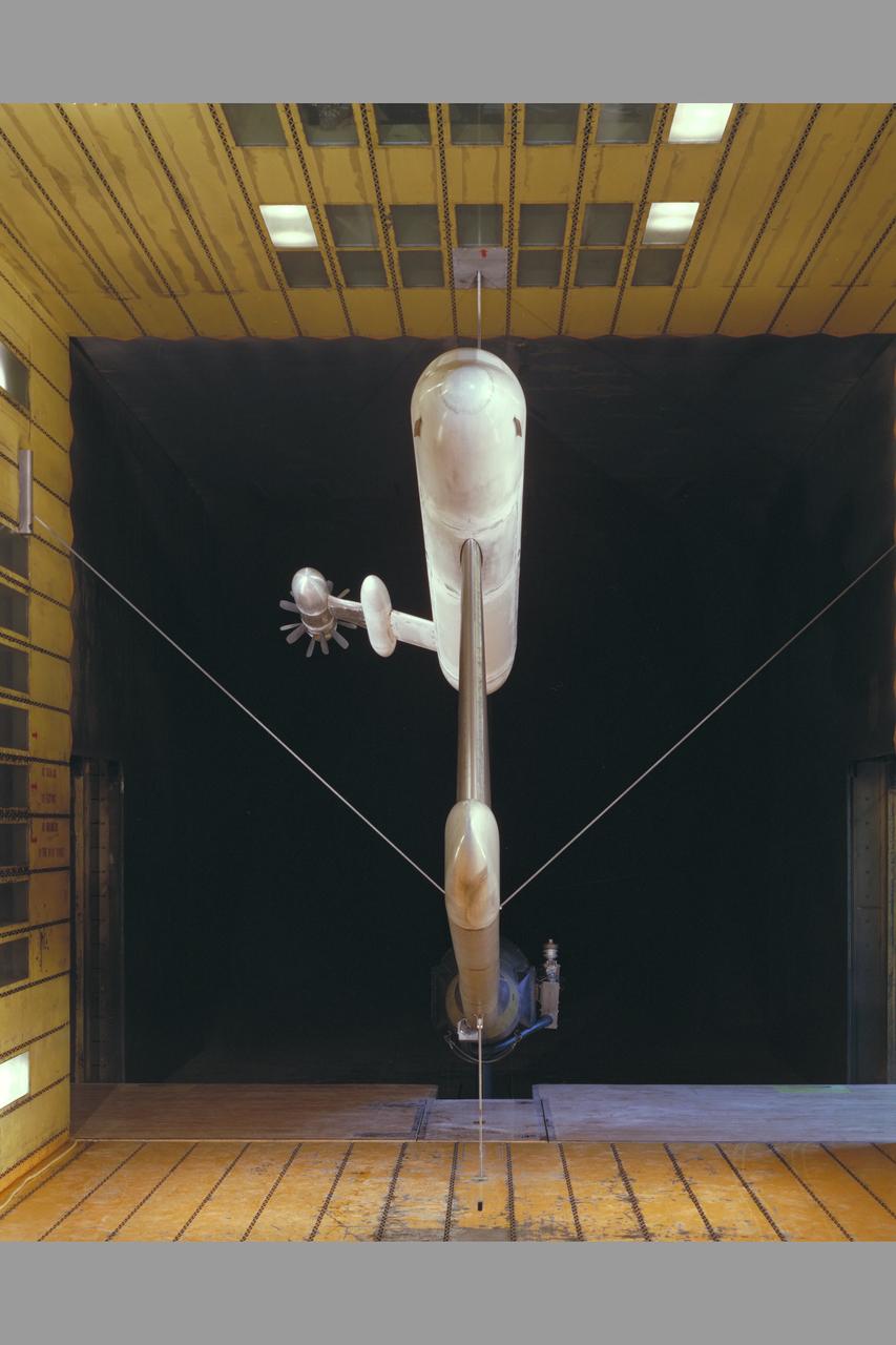
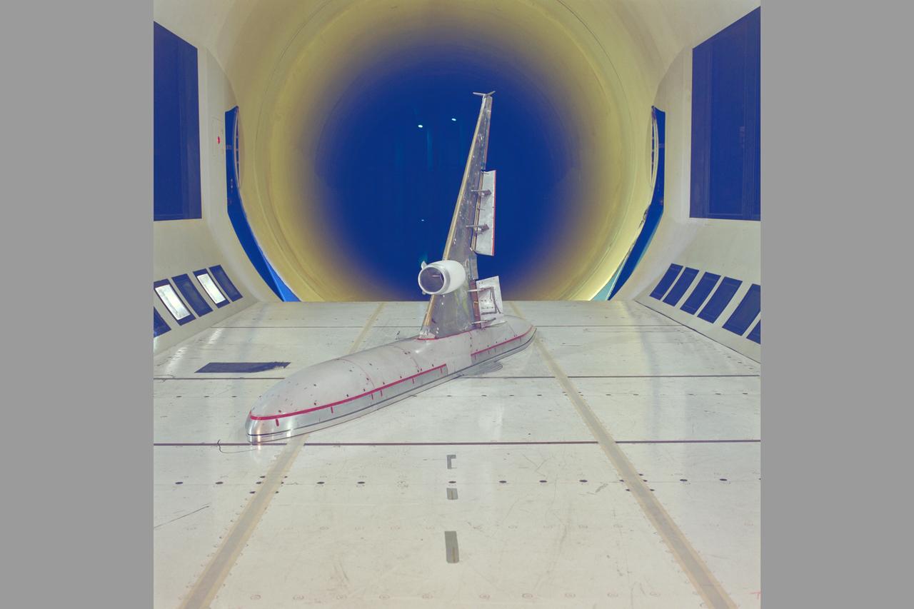
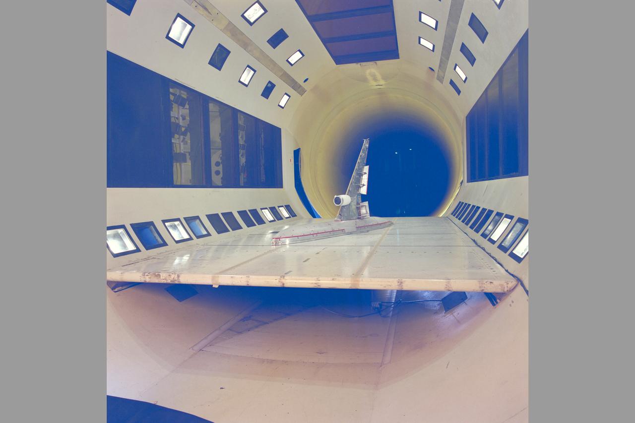
McDonnell Douglas Hub (Ultra-High Bypass) Model and SAAB Wake Rake Test 14ft W.T. Test-060-1-14, Turbo Fan Configuration
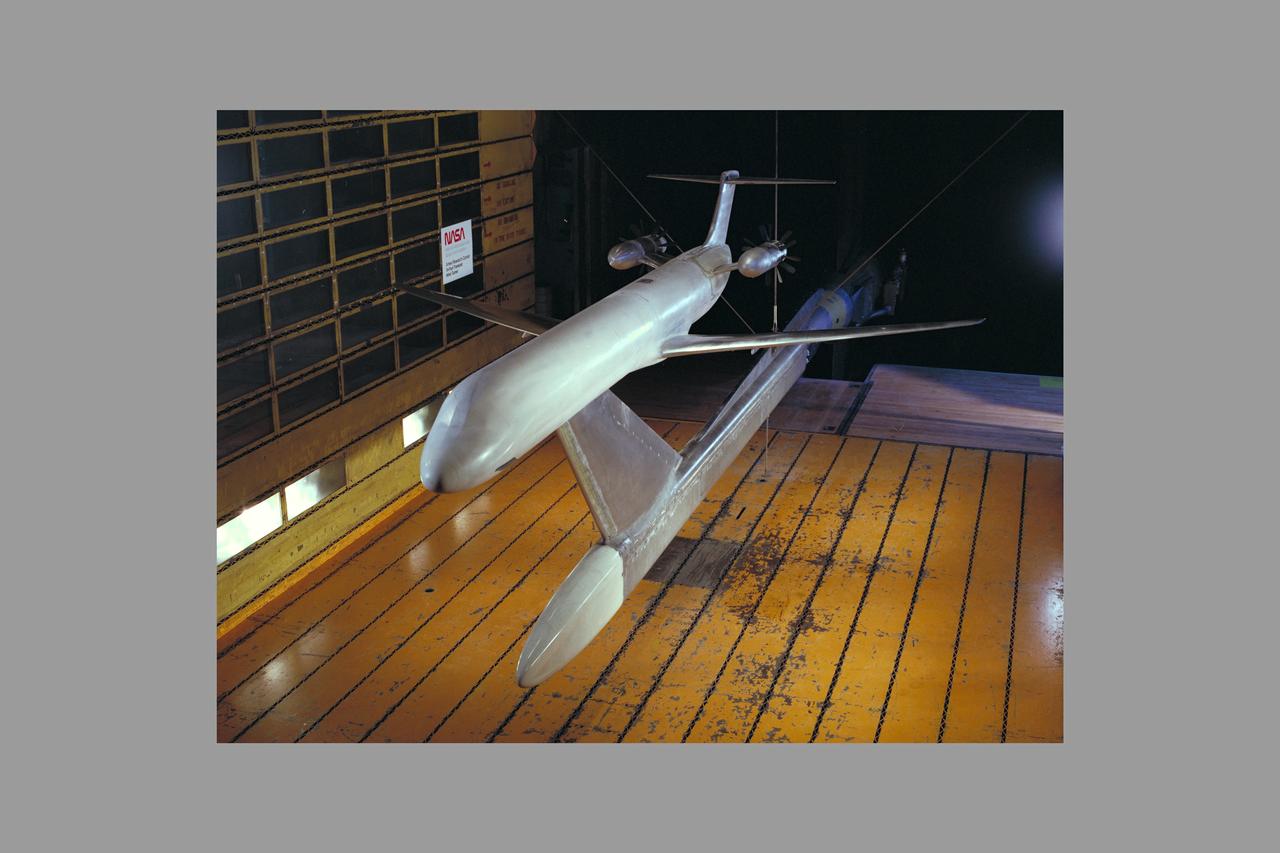
McDonnell Douglas Hub (Ultra-High Bypass) Model and SAAB Wake Rake Test 14ft W.T. Test-060-1-14, Turbo Fan Configuration
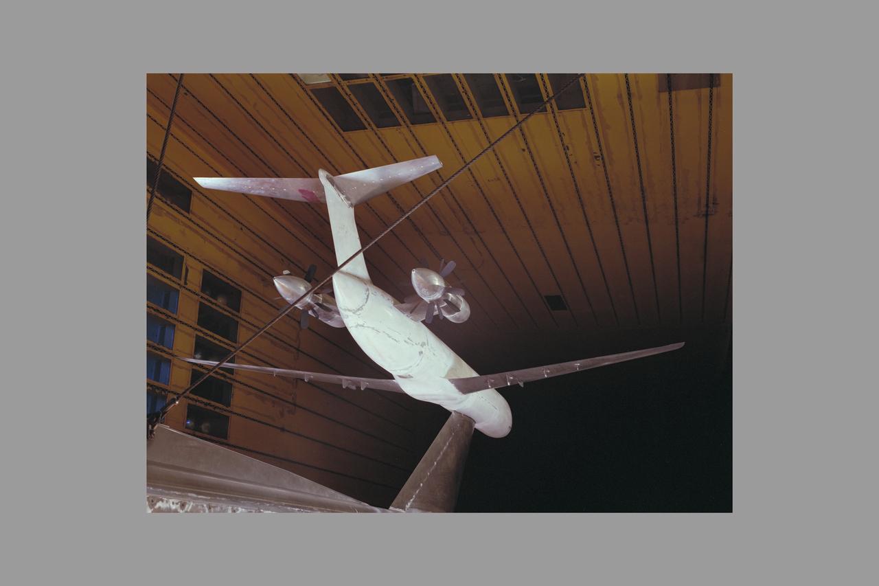
McDonnell Douglas Hub (Ultra-High Bypass) Model and SAAB Wake Rake Test 14ft W.T. Test-060-1-14, Turbo Fan Configuration
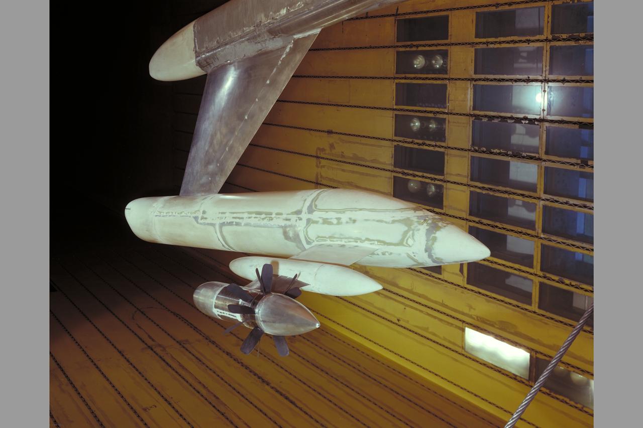
McDonnell Douglas Hub (Ultra-High Bypass) Model and SAAB Wake Rake Test 14ft W.T. Test-060-1-14, Turbo Fan Configuration

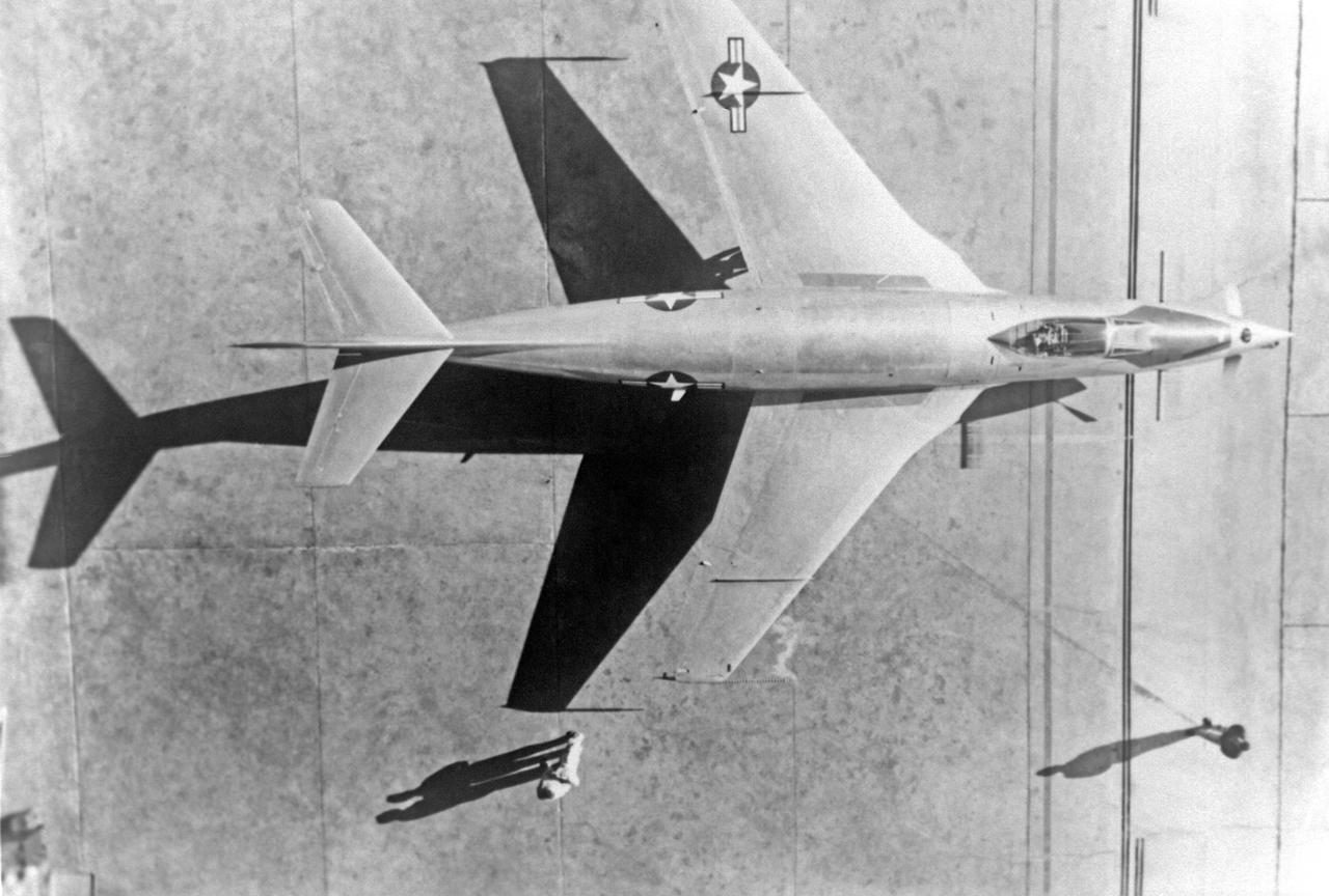
McDonnell F2H-3 Banshee: To more clearly mark the operators of this McDonnell F2H-3 Banshee, the VY of Navy has been painted out and the appropriate lettering to spell NACA has been applied. Note that the second A is of a different shape than the first. The Banjo retained Navy titles on the wings, however.
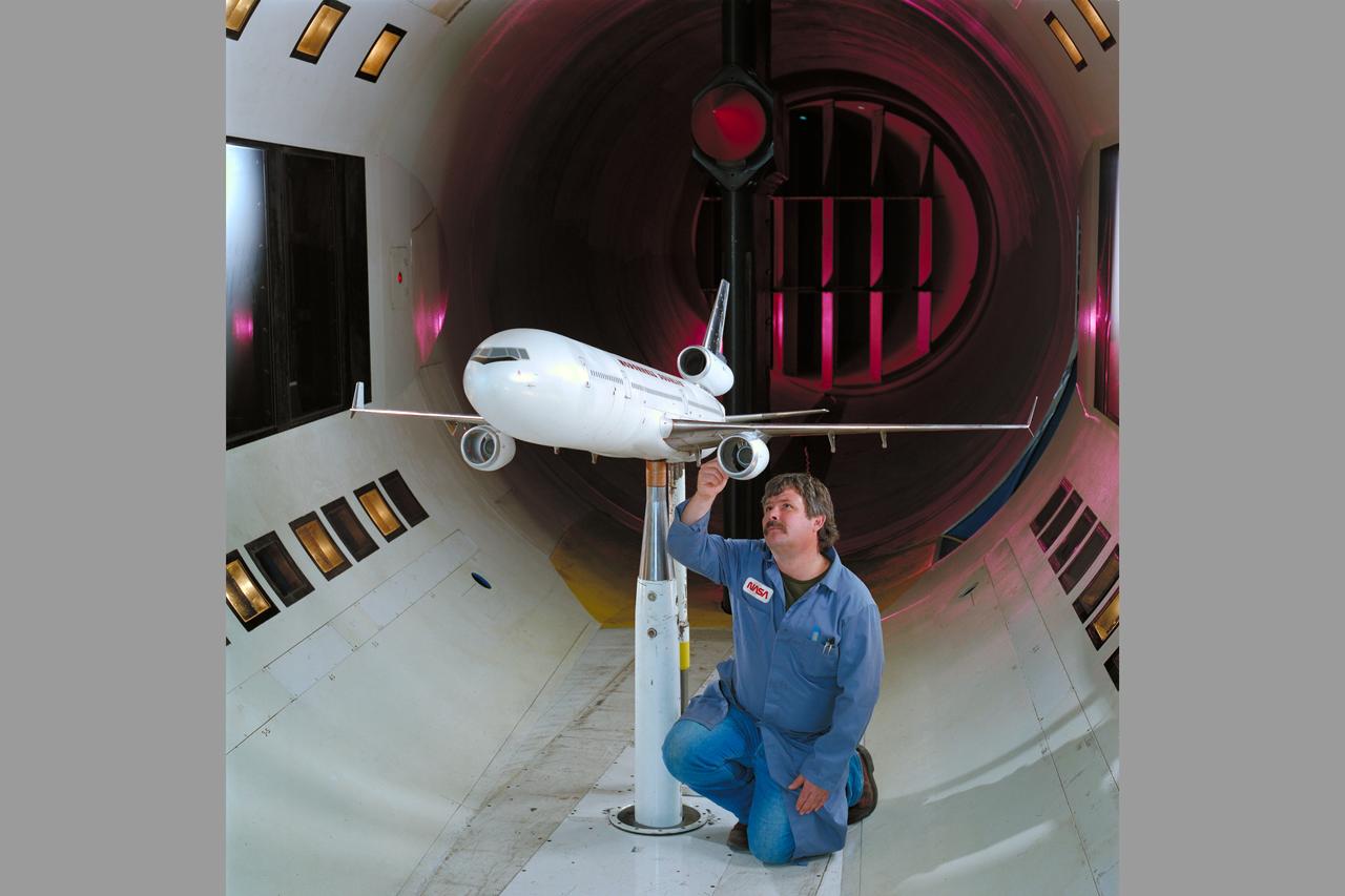
McDonnell-Douglas MD-11 Semi-span model test-12-0016 in 12ft WT
McDonnell-Douglas MD-11 Semi-span model test-12-0016 in 12ft WT
Application of blowing type boundry-layer control to the leading and trailing edge flaps of a 52 deg swept wing. 3/4 view of Aspect Ratio 2.8, taper ratio .17, 45 deg swept back wing model -3/4 front view
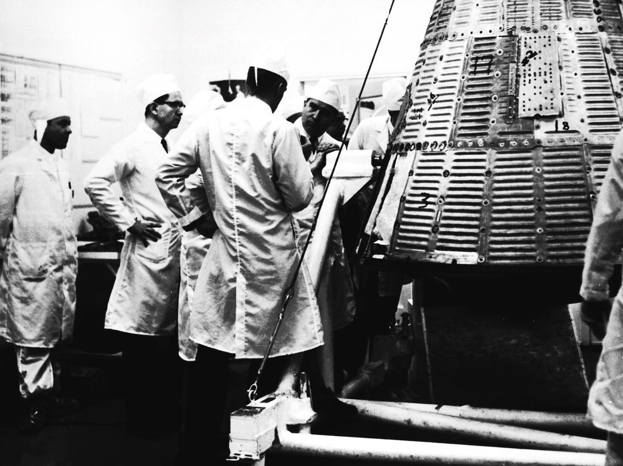
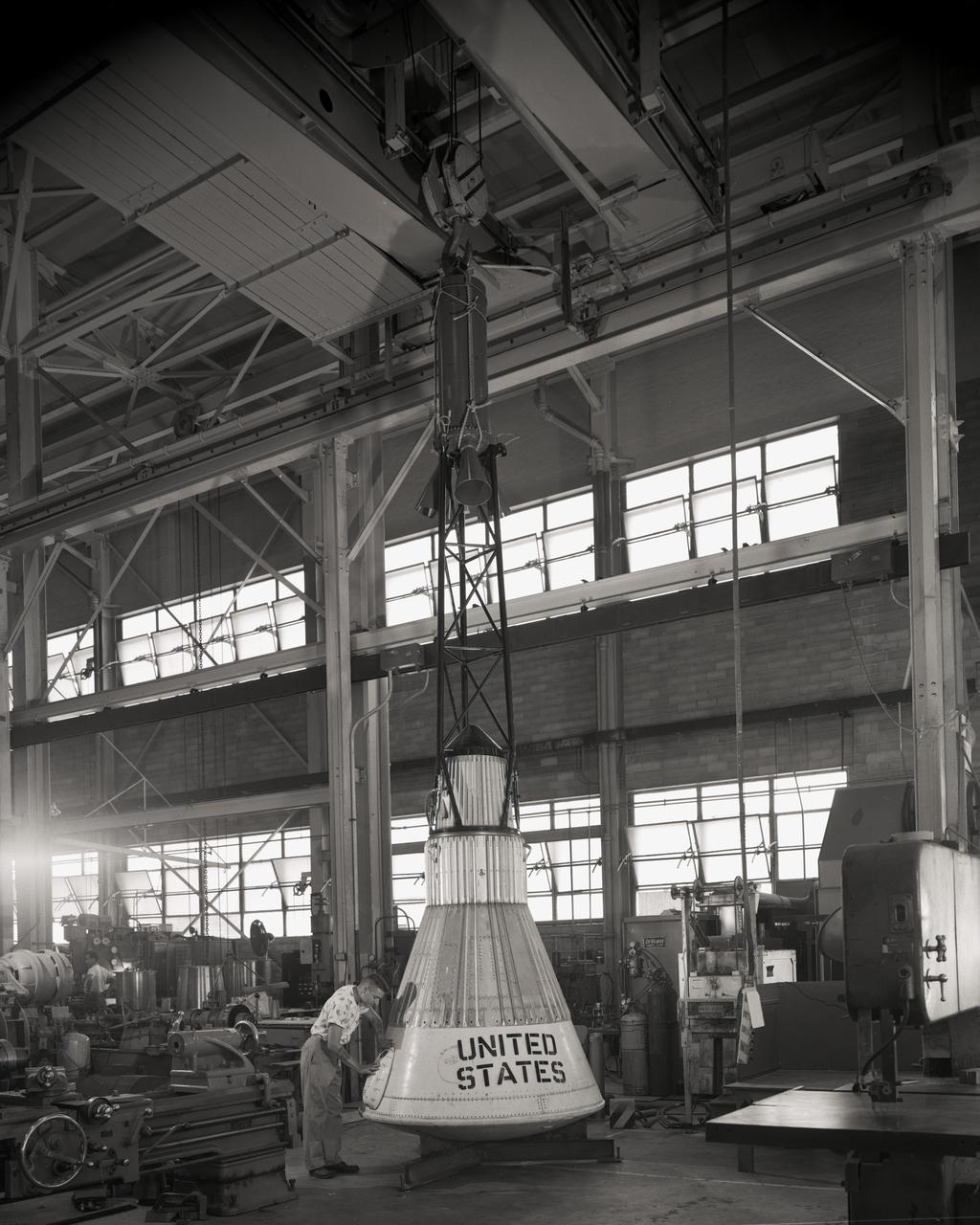
In this undated photograph, Dr. von Braun is shown during a visit to McDonnell Aircraft to inspect Mercury spacecraft manufacturing.
3/4 front view of McDonnell-Douglas Large-Scale lift fan, vertical and/or short take-off and landing (V/STOL), transport model. Francis Malerick in photograph. The McDonnell Douglas DC-9 (initially known as the Douglas DC-9) is a twin-engine, single-aisle jet airliner.
91,591 Overhead view. McDonnell XF-88B Experimental Jet Fighter. Langley used this aircraft in the mid-1950s to explore the potential of a supersonic propeller. Photographed in Engineer in Charge A History of the Langley Aeronautical Laboratory, 1917-1958 by James R. Hansen. Page 508. **Note see L57-2259 for eye level view.
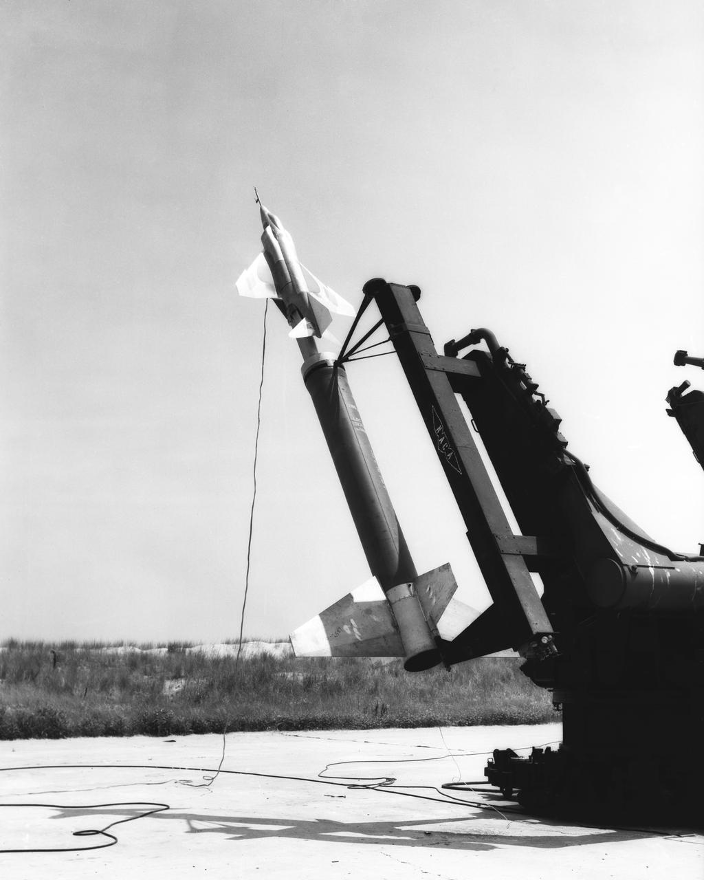
L57-2809 Rocket model of McDonnell F4-H1 airplane on Terrier launcher with Nike booster, June 17, 1957. Photograph published in A New Dimension Wallops Island Flight Test Range: The First Fifteen Years by Joseph Shortal. A NASA publication. Page 500.
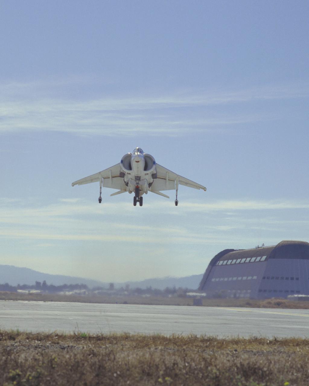
McDonnell Douglas YAV-8B (Bu. No. 158394 NASA 704 VSRA) Harrier V/STOL Systems Research Aircraft hover Note: Used in publication in Flight Research at Ames; 57 Years of Development and Validation of Aeronautical Technology NASA SP-1998-3300 fig.125
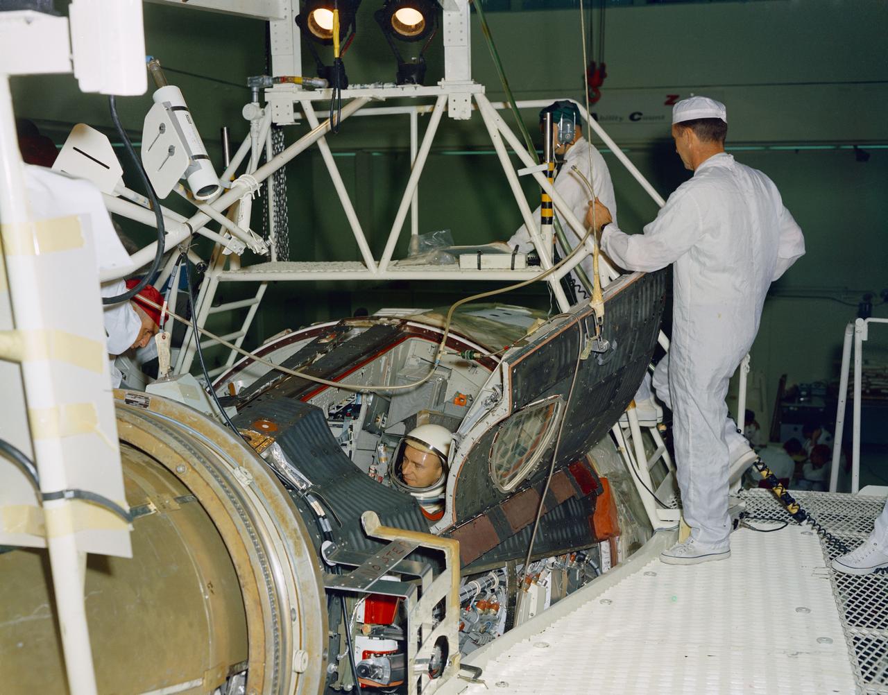
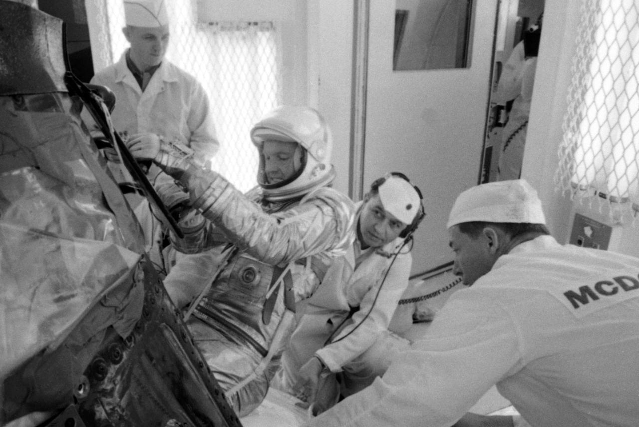
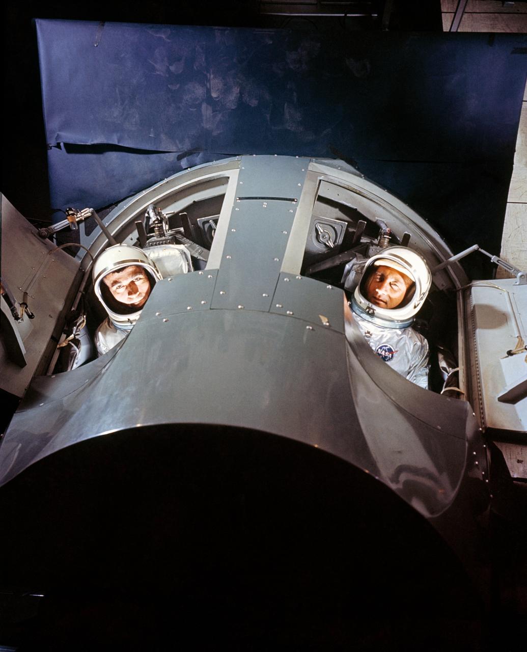
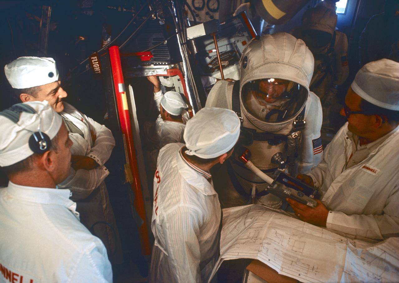
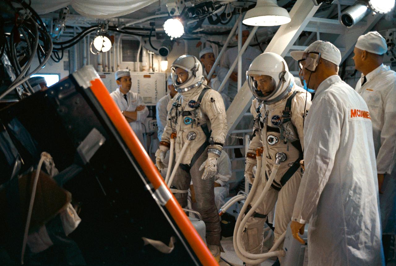
S66-34167 (21 April 1966) --- Astronauts John W. Young (right), command pilot, and Michael Collins, pilot, the prime crew of the Gemini-10 spaceflight, prepare for a Manned Altitude Test Run in the Gemini-10 spacecraft. They are in McDonnell Aircraft's 30-foot altitude chamber. Photo credit: NASA
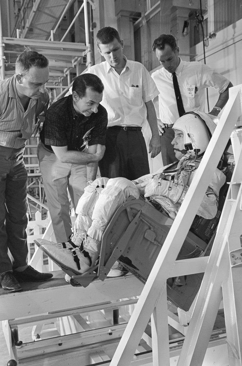
S66-23592 (8 Feb. 1966) --- Astronaut Thomas P. Stafford, command pilot of the Gemini-9 prime crew, undergoes familiarization training with the Gemini-9 spacecraft at the McDonnell plant in St. Louis. Photo credit: NASA

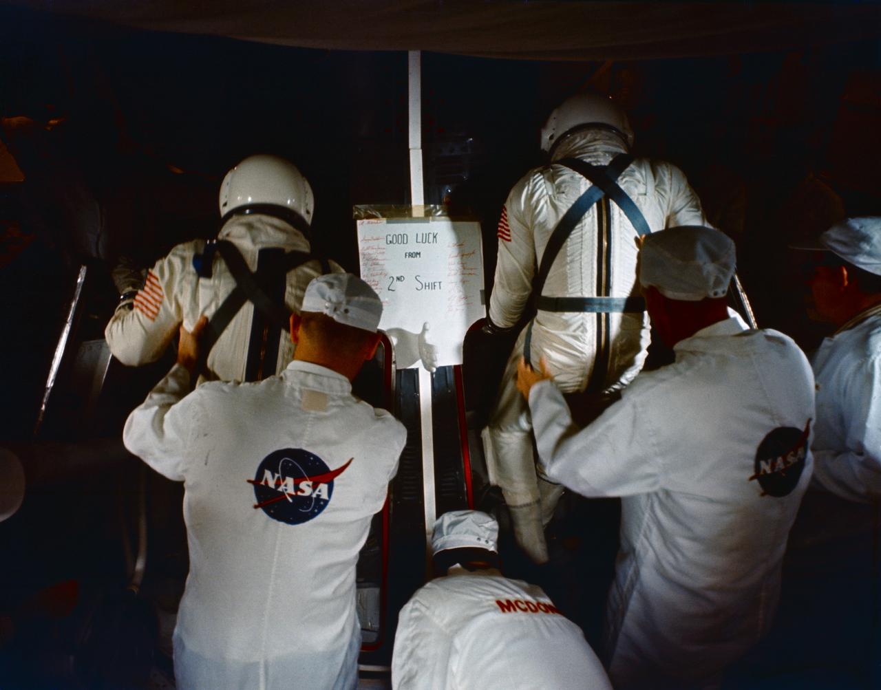
S66-32530 (14 April 1966) --- Astronauts John W. Young (right), command pilot, and Michael Collins, pilot, the prime crew of the Gemini-10 spaceflight, prepare for a Manned Altitude Test Run in the Gemini-10 spacecraft. They are in McDonnell Aircraft's 30-feet altitude chamber. Photo credit: NASA
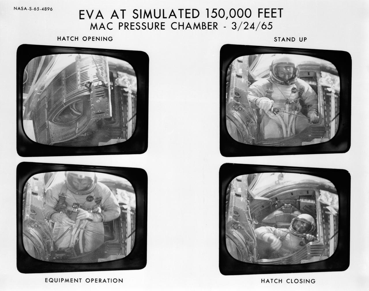
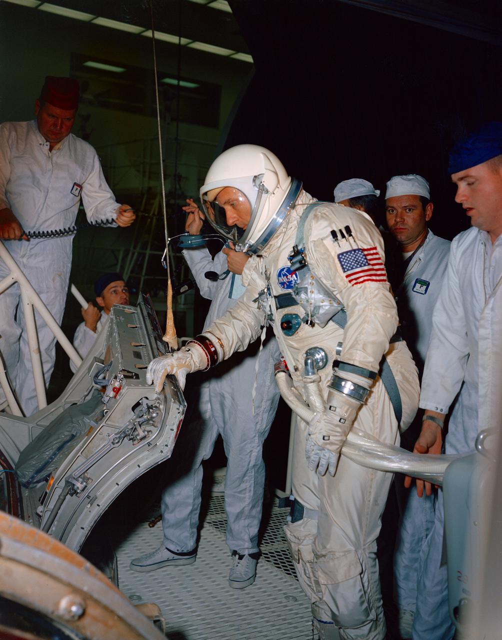
S65-04896 (24 March 1965) --- Astronaut Edward H. White II, pilot of the Gemini-Titan 4 prime crew, is shown in the pressure chamber at McDonnell Aircraft Corp, St. Louis, Mo. during the simulation of extravehicular activity (EVA) at an altitude of 150,000 feet.
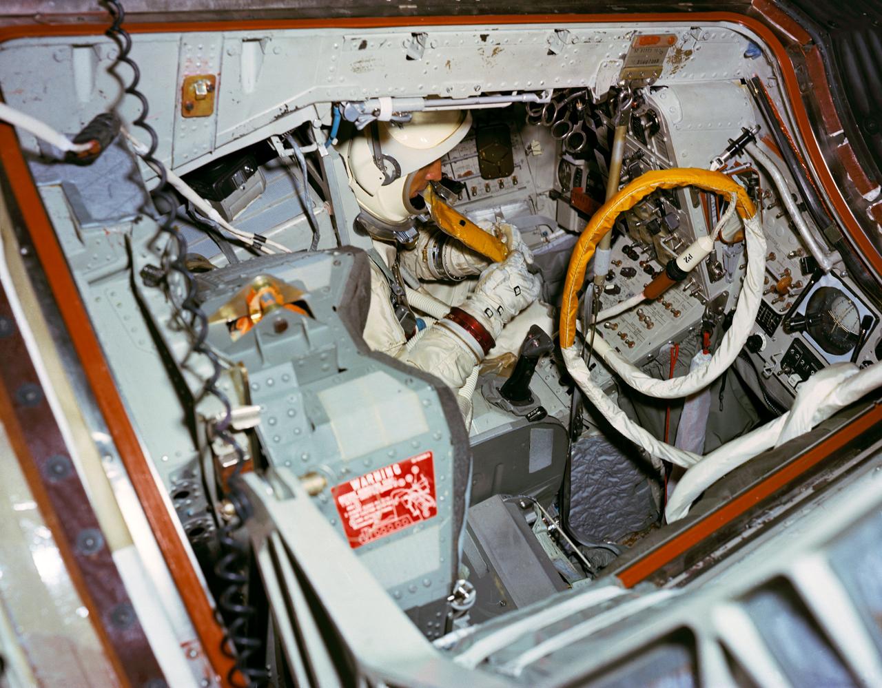
S66-51054 (15 Aug. 1966) --- Astronaut James A. Lovell Jr., prime crew command pilot of the Gemini-12 space mission, simulates using space food packet while seated in the Gemini-12 spacecraft in the 30-feet Altitude Chamber at McDonnell Aircraft Corporation, St. Louis, Missouri. Photo credit: NASA
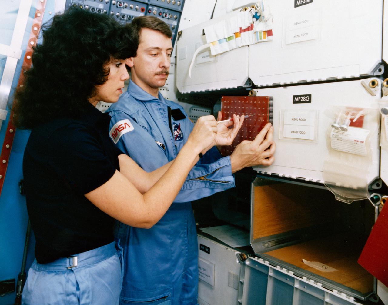
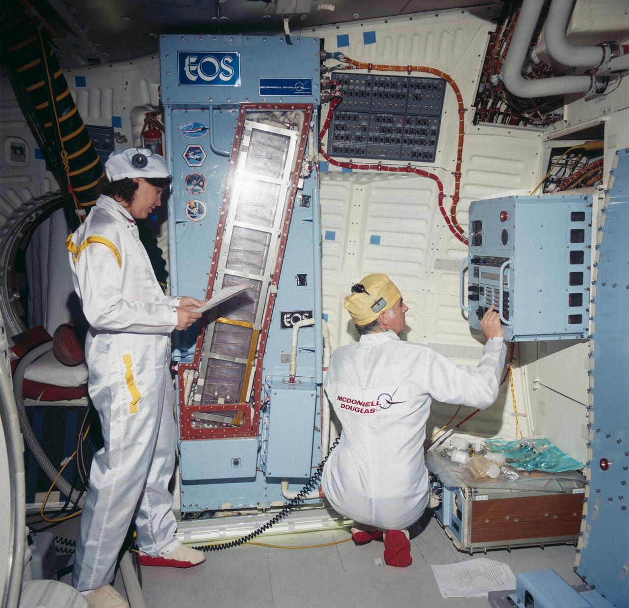
S84-35757 (May 1984) --- Astronaut Judith A. Resnik, 41-D mission specialist, and Charles Walker, payload specialist for that June 1984 flight, prepare for some scheduled intravehicular activity involving the continuous flow electrophoresis systems (CFES) experiment. CFES will join the six-member crew aboard the Earth-orbiting Discovery for a seven day mission. The two share in preparing a sample to be processed by the CFES. In the background are stowage lockers and a CFES trainer-- part of the Shuttle one-g trainer at NASA's Johnson Space Center (JSC). Walker, an engineer at McDonnell Douglas Astronautics Co. in St. Louis, Missouri, will be the first Shuttle payload specialist to represent a project designed for commercial purposes. As payload specialist, his job will be to run the materials electrophoresis-operations-in-space project. The project is aimed at separating large quantities of biological materials in space for ultimate use in new pharmaceuticals. The photo was taken by a McDonnell Douglas photographer.
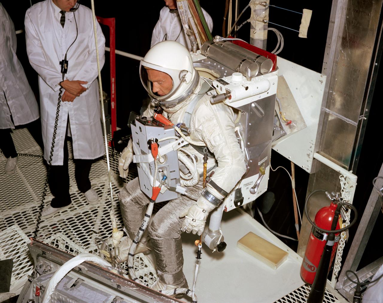
S66-51073 (15 Aug. 1966) --- Astronaut Edwin E. Aldrin Jr., prime crew pilot of the Gemini-12 spaceflight, undergoes evaluation procedures with the Astronaut Maneuvering Unit in the 30-foot altitude chamber at McDonnell. The suited Aldrin is wearing an AMU backpack and an Extravehicular Life Support System (ELSS) chest pack. Photo credit: NASA
Mc Donnell Douglas MD-11 Model in Ames 12ft. W.T. (1st Non-NASA customer of the refurbished W.T.)
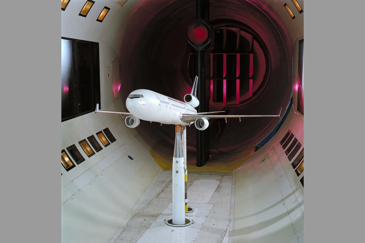
Mc Donnell Douglas MD-11 Model in Ames 12ft. W.T. (1st Non-NASA customer of the refurbished W.T.)

Mc Donnell Douglas MD-11 Model in Ames 12ft. W.T. (1st Non-NASA customer of the refurbished W.T.)
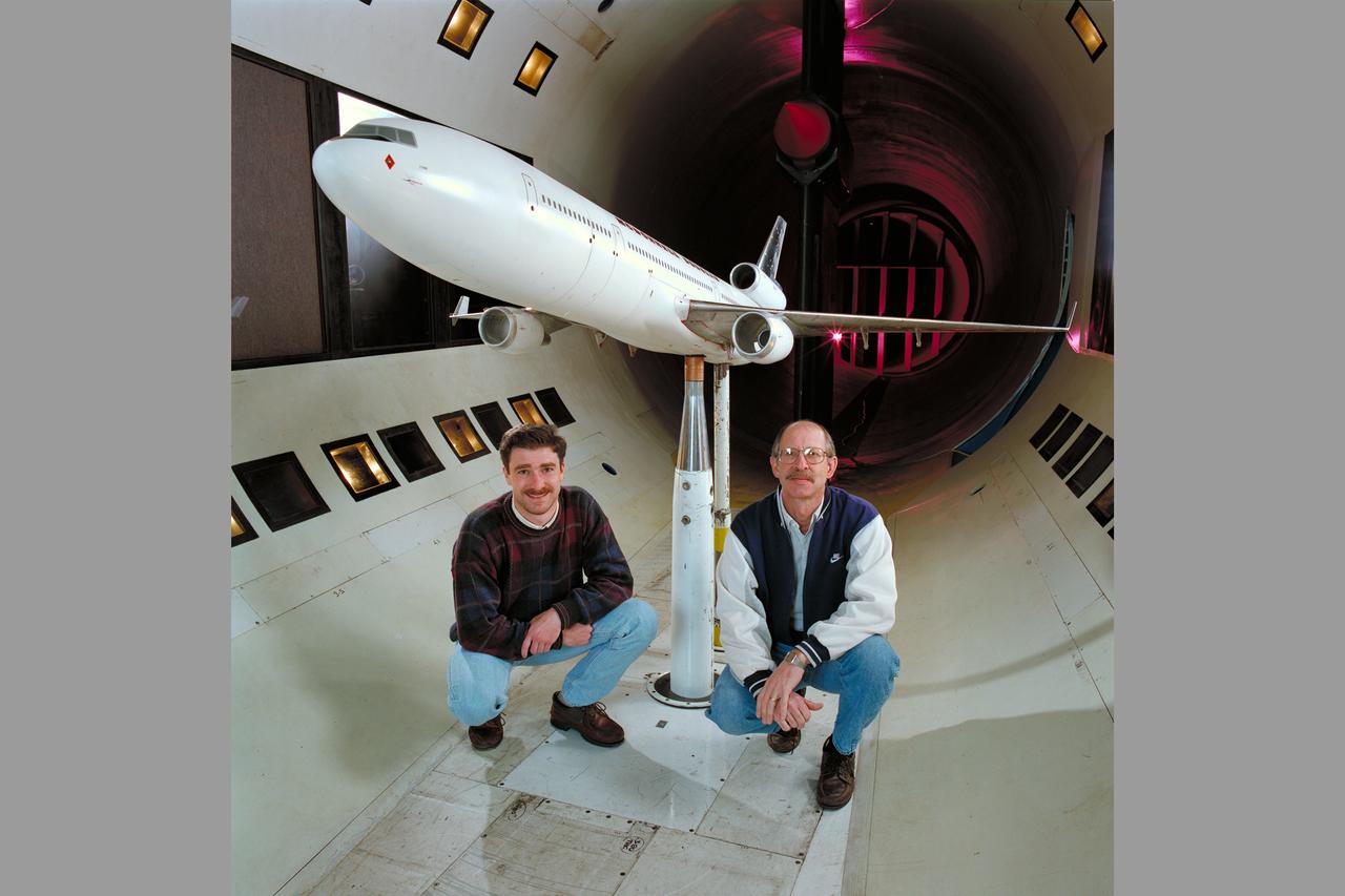
Mc Donnell Douglas MD-11 Model in Ames 12ft. W.T. with members of the MC Donnell Douglas crew (1st Non-NASA customer of the refurbished W.T.)
Mc Donnell Douglas MD-11 Model in Ames 12ft. W.T. (1st Non-NASA customer of the refurbished W.T.)

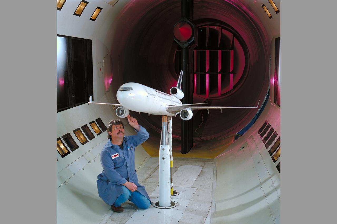
Mc Donnell Douglas MD-11 Model in Ames 12ft. W.T. with Ron Strong (1st Non-NASA customer of the refurbished W.T.)
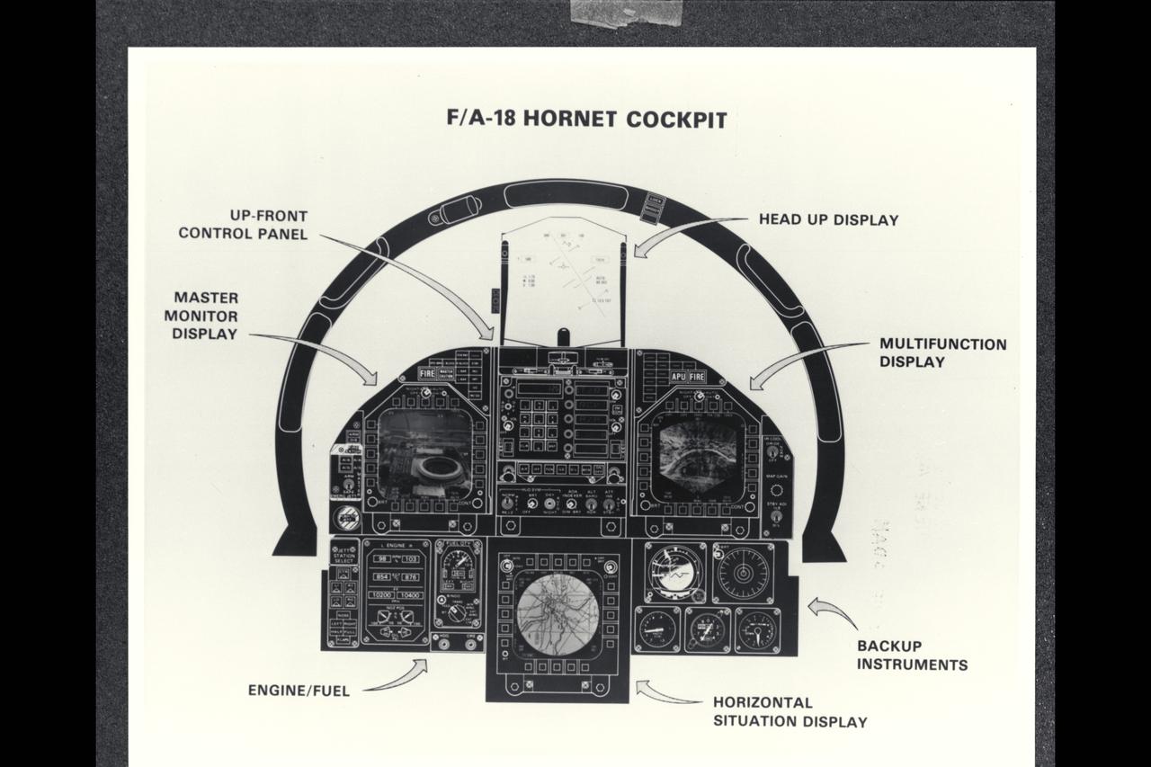
McDonnell Douglas F/A-18A Hornet cockpit drawing
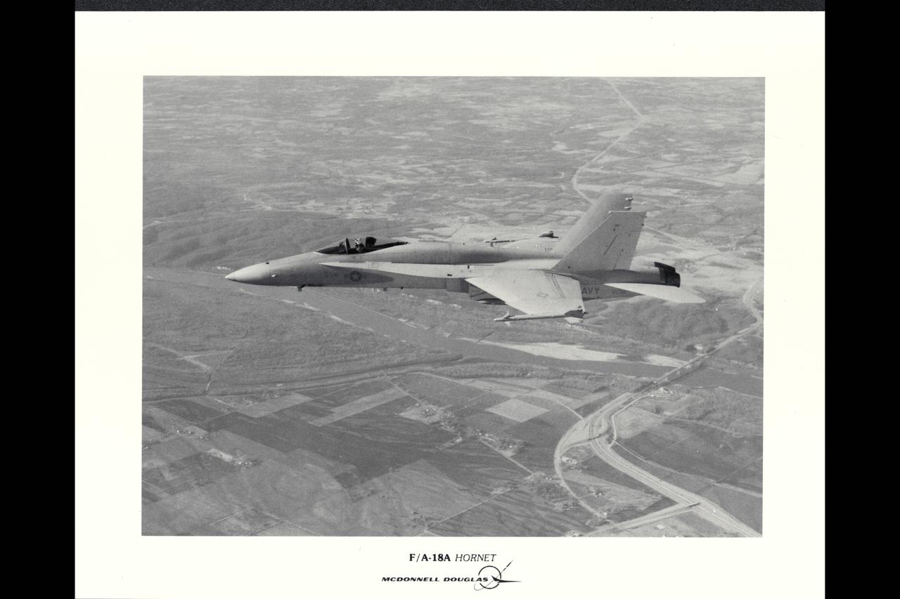
McDonnell Douglas F/A-18A Hornet in flight
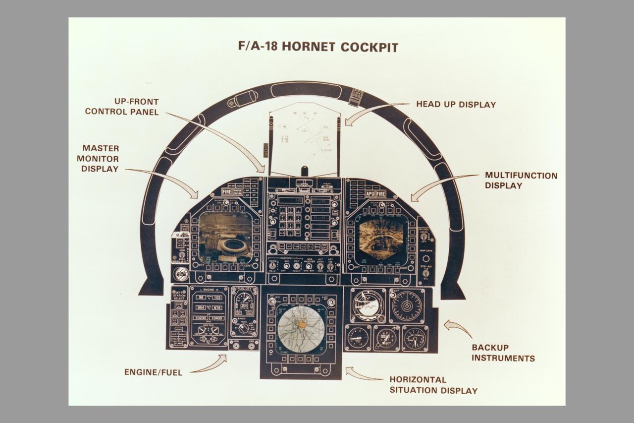
McDonnell Douglas F/A-18A Hornet cockpit drawing
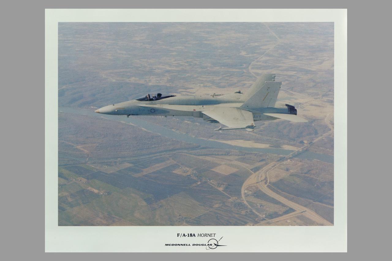
McDonnell Douglas F/A-18A Hornet in flight
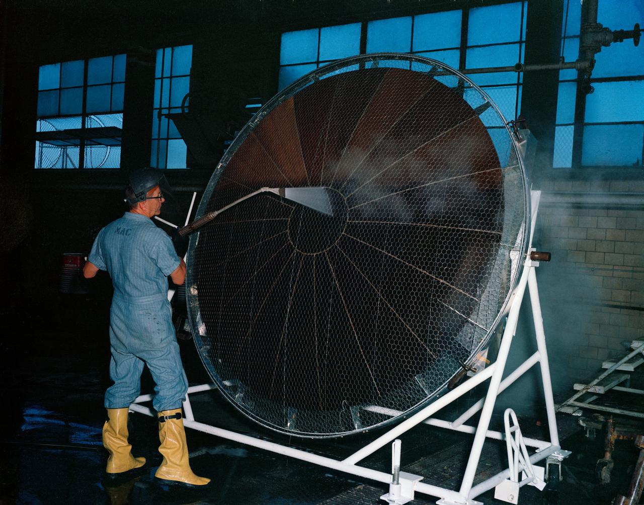
S63-16250 (1963) --- Workman cleaning metal framed heat shield to be used on Mercury spacecraft. Photo credit: NASA
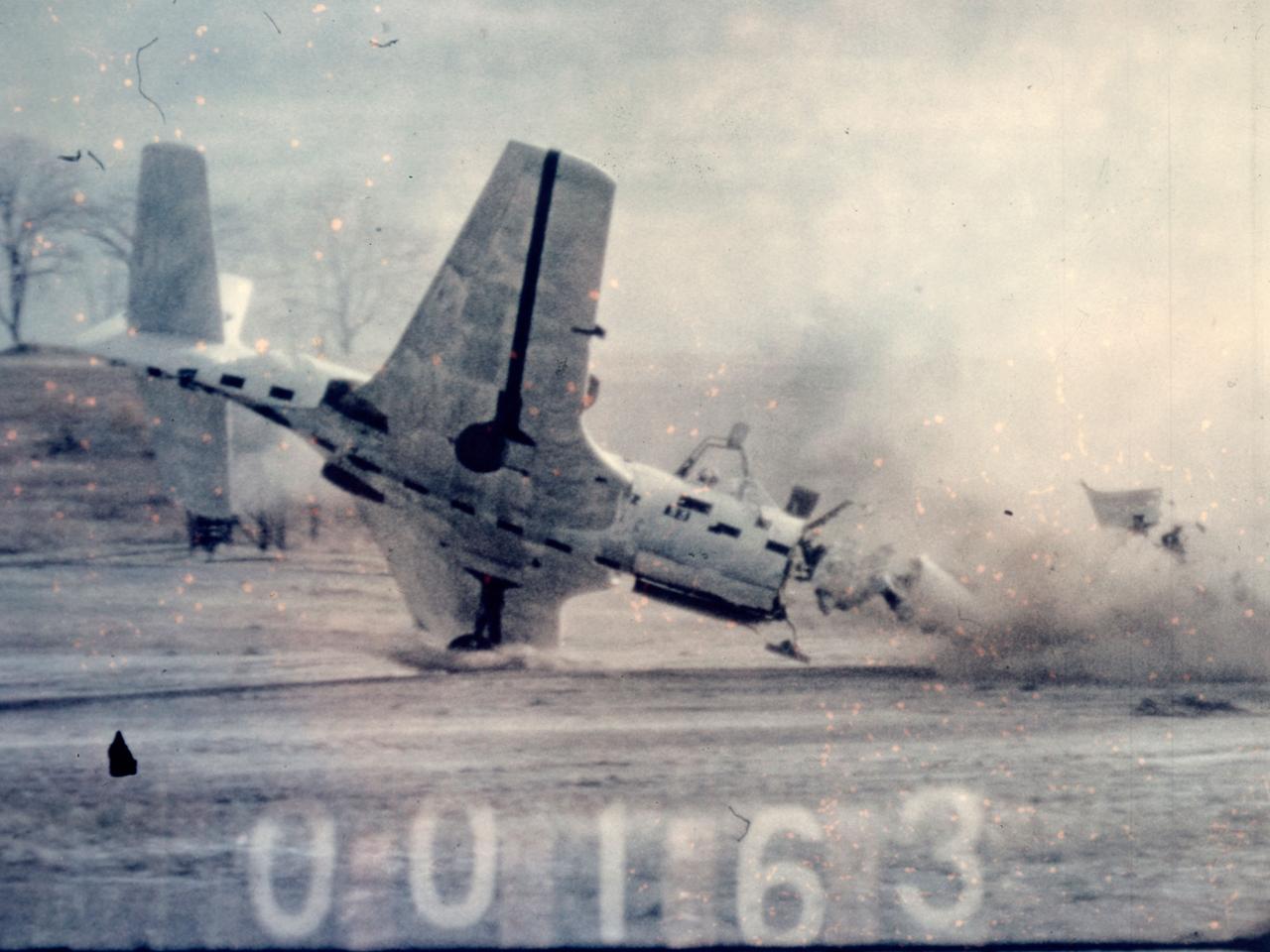
Researchers at the National Advisory Committee for Aeronautics (NACA) Lewis Flight Propulsion Laboratory purposely wreck a McDonnell FH-1 Phantom as part of the laboratory’s Crash Fire Program. NACA Lewis researchers created the program in 1949 to investigate methods for improving survival rates for take-off and landing-type crashes. In these types of crashes, the passengers often survived the impact only to perish in the ensuing fire. Previously there had been little information on the nature of post-crash fires, and it was difficult to use analytical studies in this area. Irving Pinkel, Chief of the Lewis Flight Propulsion Division, was the primary researcher. He enlisted flight safety specialist and aeronautics researchers G. Merritt Preston and Gerard Pesman, mechanical engineer Dugald Black, and others. The tests were conducted at the nearby Ravenna Arsenal using decommissioned Air Force fighter and transport aircraft. The pilotless aircraft were accelerated down a rail on a 1700-foot track at take-off speeds and run into barriers to simulate a variety of different types of crashes. The first barrier stripped off the landing gears and another briefly sent the aircraft off the ground before it crashed into a dirt mound. Telemetry and high-speed cameras were crucial elements in these studies. NACA Lewis photographer Bill Wynne developed a method for inserting timekeeping devices on test film that were able to show time to one thousandth of a second.
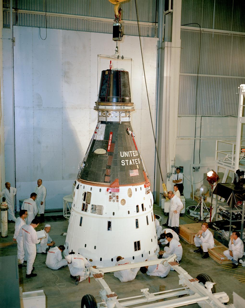
S65-43449 (19 Aug. 1965) --- Photograph of the Gemini-5 spacecraft in the McDonnell test facility during stowage review.
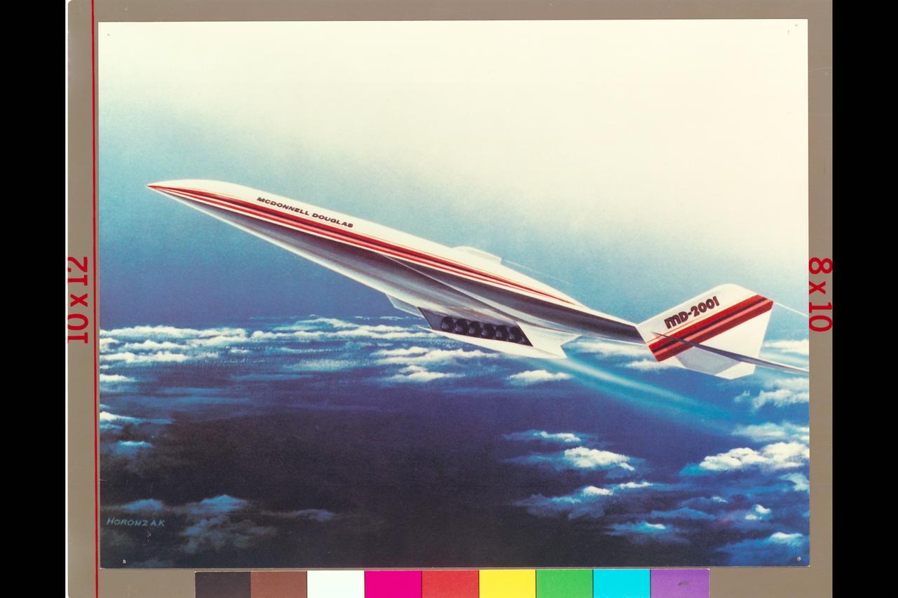
Art from McDonnell Douglas National Aerospace Plane (NASP) Md Donnell Douglas MD-2001 (artist: Horonzak)
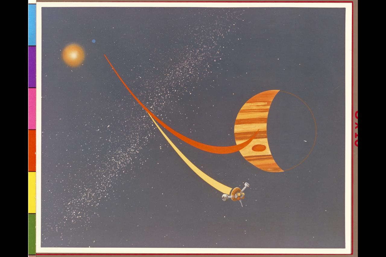
Pioneer Galileo mission trajectory artwork (ref: McDonnell Douglas May, 77 # D4C-117575-4)
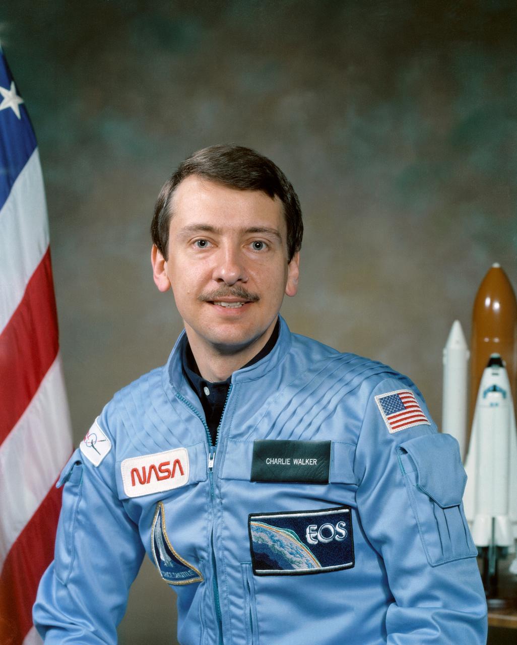
S84-27269 (16 Feb 1984) --- Astronaut Charles (Charlie) D. Walker, payload specialist and McDonnell-Douglas Civilian Engineer.
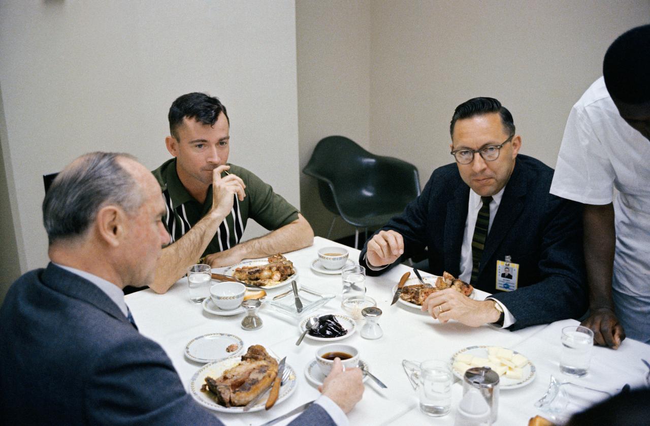
S65-20428 (23 March 1965) --- Astronaut John W. Young (center), pilot of the Gemini-Titan 3 flight, is shown during a steak breakfast which he was served about two hours prior to the 9:24 a.m. (EST) GT-3 launch. At left is J.S. McDonnell, board chairman and Chief Executive Officer of the McDonnell Aircraft Corporation. Dr. Charles A. Berry, chief of Center Medical Programs, is at right.
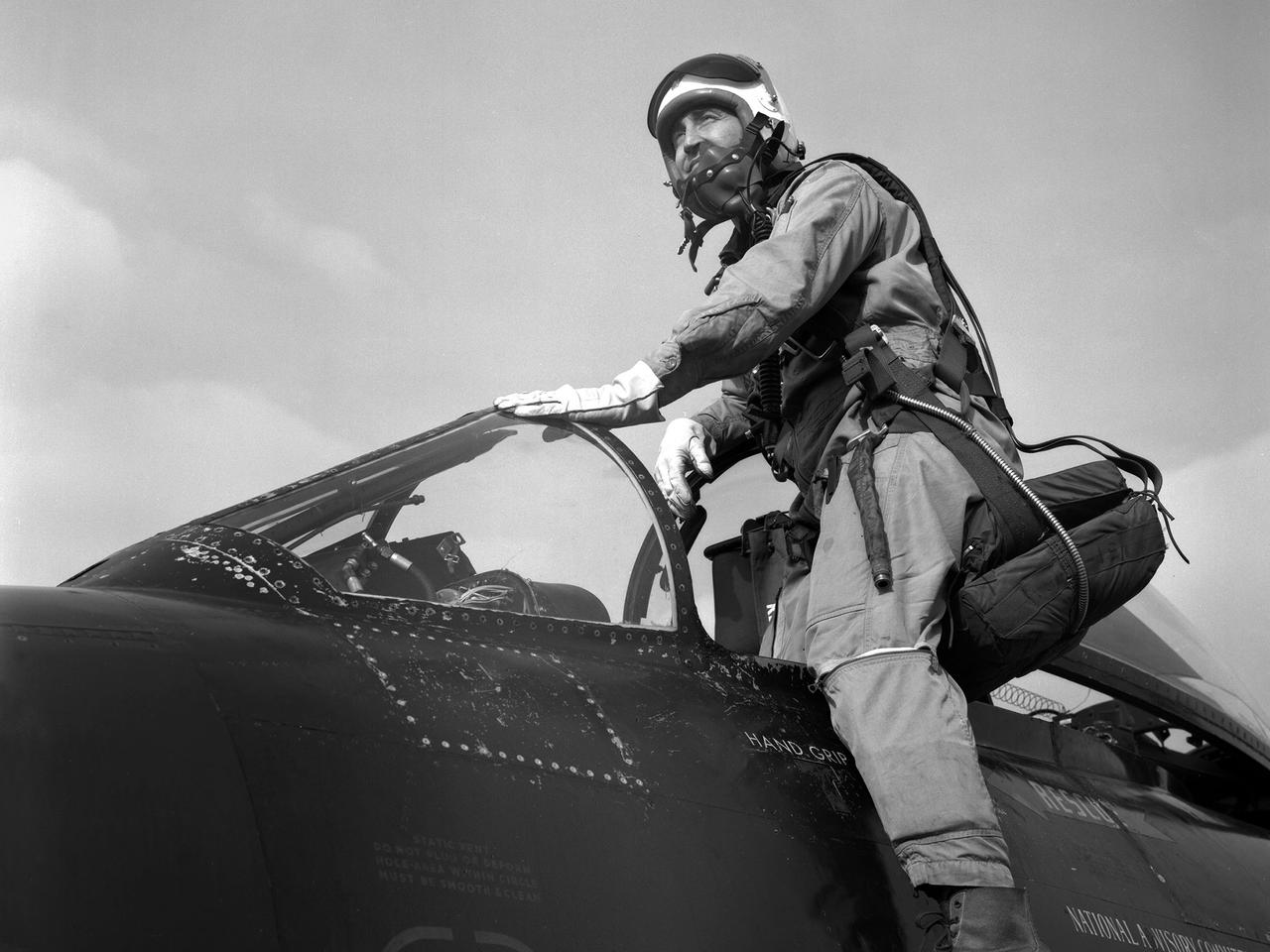
Pilot Joe Algranti climbs into the cockpit of a McDonnell F2H-2B Banshee on the tarmac at the National Advisory Committee for Aeronautics (NACA) Lewis Flight Propulsion Laboratory. Nine months later the laboratory became part of the new National Aeronautics and Space Administration, and the NACA logo was permanently removed from the hangar. Algranti served as a Navy fighter pilot from 1946 to 1947 and earned a Physics degree from the University of North Carolina. He joined the NACA Lewis staff in 1951 witnessed the technological transformation from high speed flight to space. At Lewis Algranti piloted icing research flights, operated the liquid-hydrogen pump system for Project Bee, and served as the primary test subject for the Multi-Axis Space Test Inertia Facility (MASTIF). The MASTIF was a device used to train the Mercury astronauts how to control a spinning capsule. In 1960, Algranti and fellow Lewis pilots Warren North and Harold Ream transferred to NASA’s Space Task Group at Langley to actively participate in the space program. Two years later, Algranti became the Chief of Aircraft Operations and Chief Test Pilot at NASA’s new Manned Space Center in Houston. Algranti earned notoriety in 1968 when he test flew the first Lunar Landing Training Vehicle. He operated the vehicle four minutes before being forced to eject moments before it impacted the ground. Algranti also flew the NASA’s modified Boeing 747 Shuttle Carrier Aircraft, the Super Guppy, and the KC-135 "Vomit Comet" training aircraft. He retired in 1992 with over 40 years of NASA service.

KENNEDY SPACE CENTER, FLA. -- CHAMBER TEST - Project Mercury astronaut Virgil I. 'Gus' Grissom, assisted by McDonnell technicians, leaves Mercury spacecraft, dubbed Liberty Bell 7, following simulated flight.
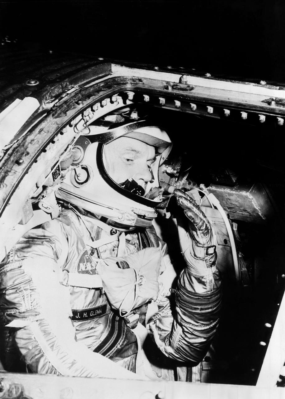
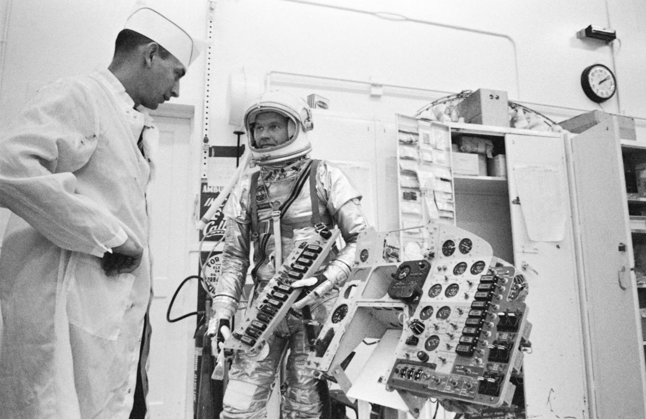
S62-01021 (1962) --- Astronaut John H. Glenn Jr. during training procedures in a trainer at the McDonnell Douglas training facility in St. Louis, Missouri. Photo credit: NASA
Front View of McDonald XP-85 Plan Model. Parasite Airplane designed to be carried in the B-36 bombay (never built) At the time it was the smallest Jet powered airplane. The McDonnell XF-85 Goblin was an American prototype fighter aircraft conceived during World War II by McDonnell Aircraft. It was intended to be deployed from the bomb bay of the giant Convair B-36 bomber as a parasite fighter. The XF-85's intended role was to defend bombers from hostile interceptor aircraft, a need demonstrated during World War II
S63-03957 (1963) --- NASA and McDonnell Aircraft Corp. spacecraft technicians assist astronaut L. Gordon Cooper Jr. into his spacecraft prior to undergoing tests in the altitude chamber. These tests are used to determine the operating characteristcs of the overall environmental control system. Photo credit: NASA
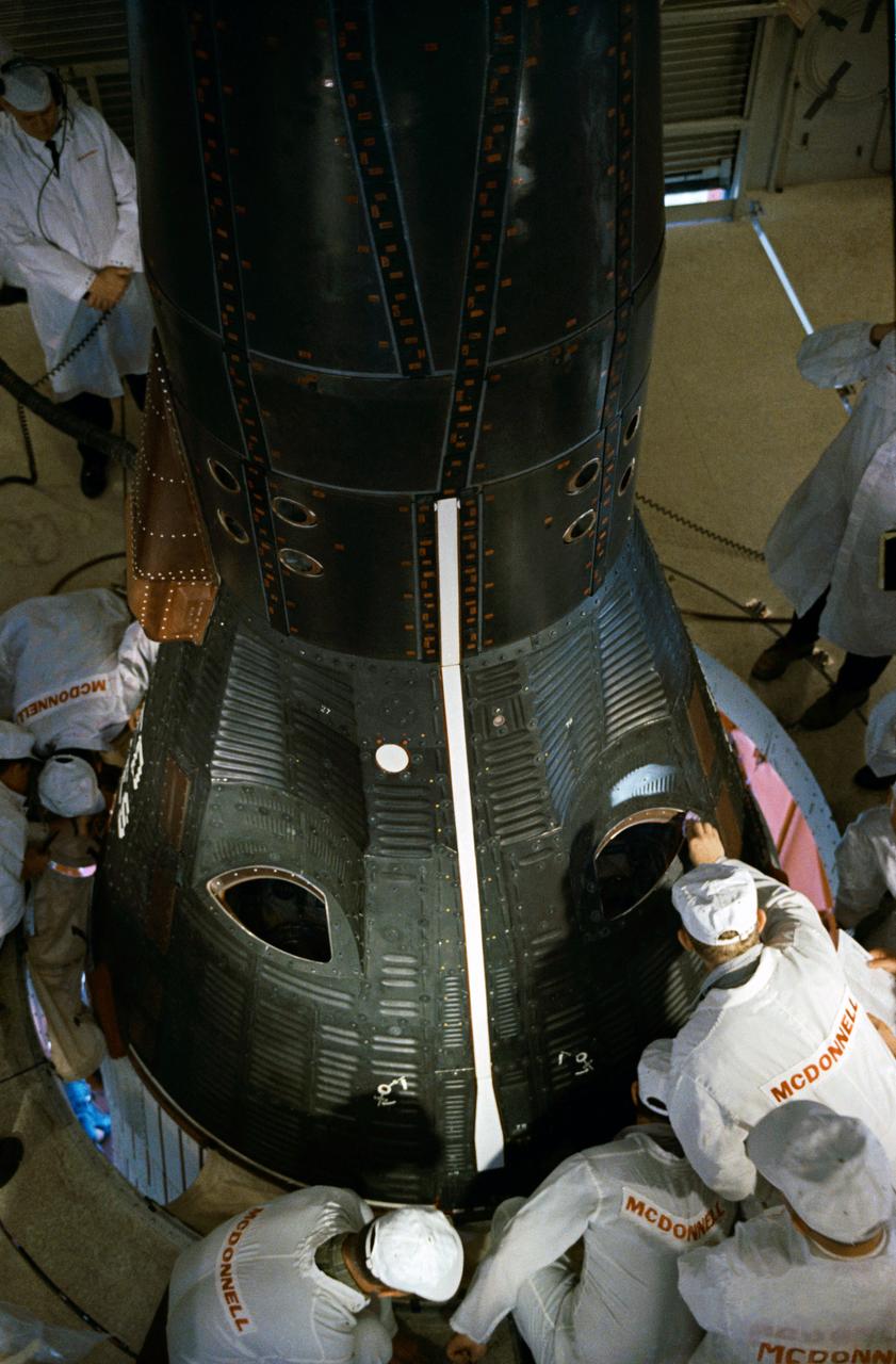
S66-47635 (21 July 1966) --- McDonnell Aircraft Corporation personnel bolt the Gemini-11 spacecraft to a support ring for bore sighting in the Pyrotechnic Installation Building, Merritt Island, during checkout and preflight preparations at the Kennedy Space Center. Photo credit: NASA
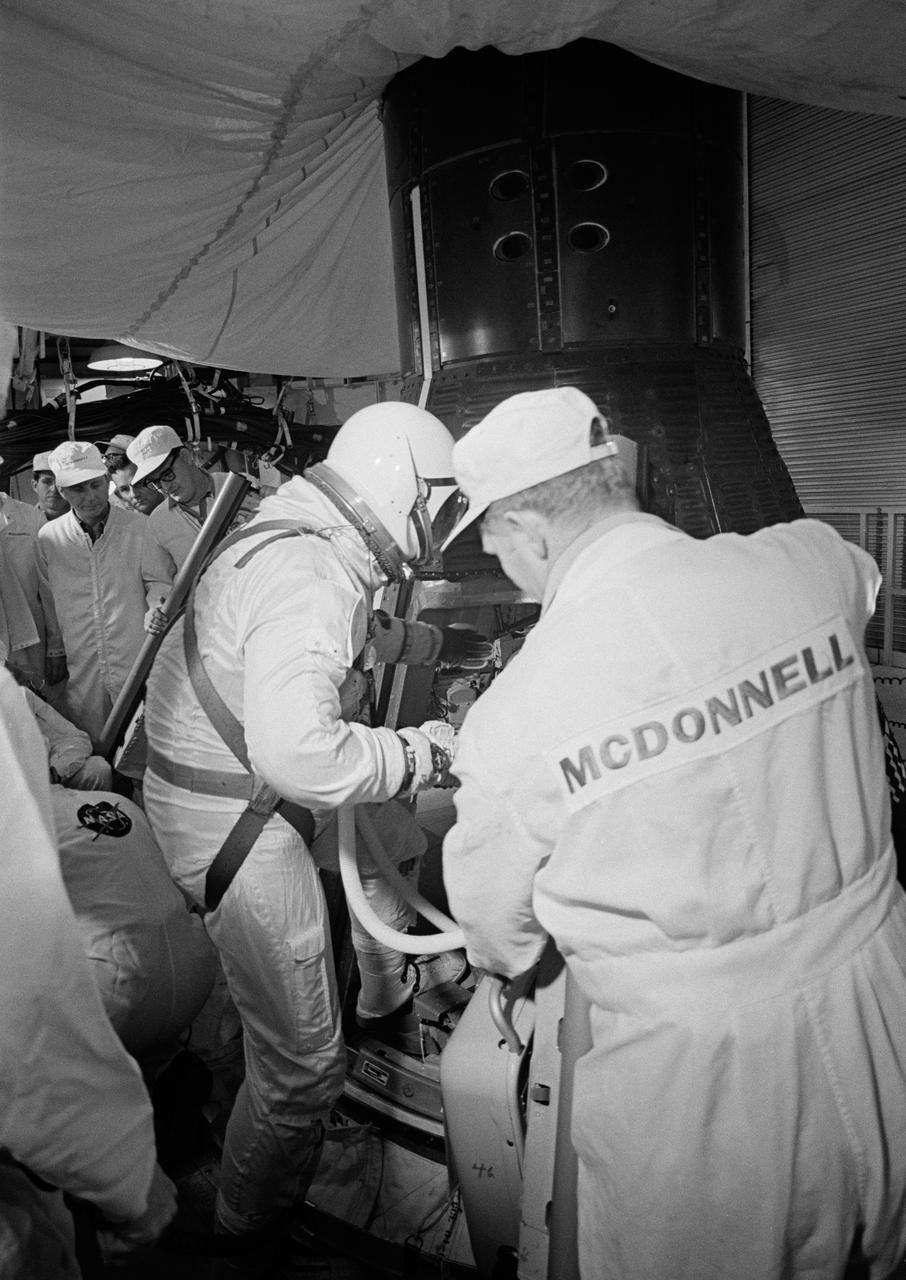
S65-20604 (23 March 1965) --- Astronaut John W. Young, the pilot of the Gemini-Titan 3 three-orbit mission, is assisted by a McDonnell Aircraft Corp. engineer as he enters the Gemini spacecraft in the white room atop the Gemini launch vehicle.
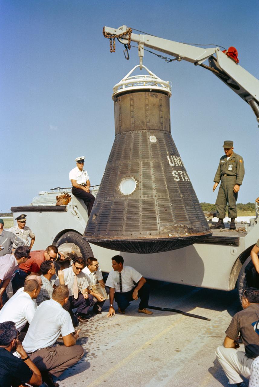
S64-14861 (1962) --- Department of Defense (DOD) recovery personnel and spacecraft technicians from NASA and McDonnell Aircraft Corp., inspect astronaut John Glenn's Mercury spacecraft, Friendship 7, following its return to Cape Canaveral after recovery in the Atlantic Ocean. Photo credit: NASA
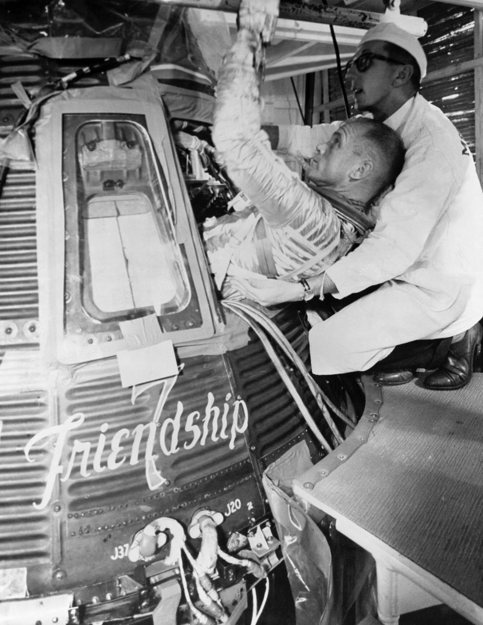
S62-00994 (1962) --- Astronaut John H. Glenn Jr., pilot of the Mercury-Atlas 6 mission, practices insertion into the Mercury "Friendship 7? spacecraft, with help of a McDonnell Aircraft Corporation technician, during MA-6 preflight training activity at Cape Canaveral, Florida. He is wearing the full pressure suit. Photo credit: NASA
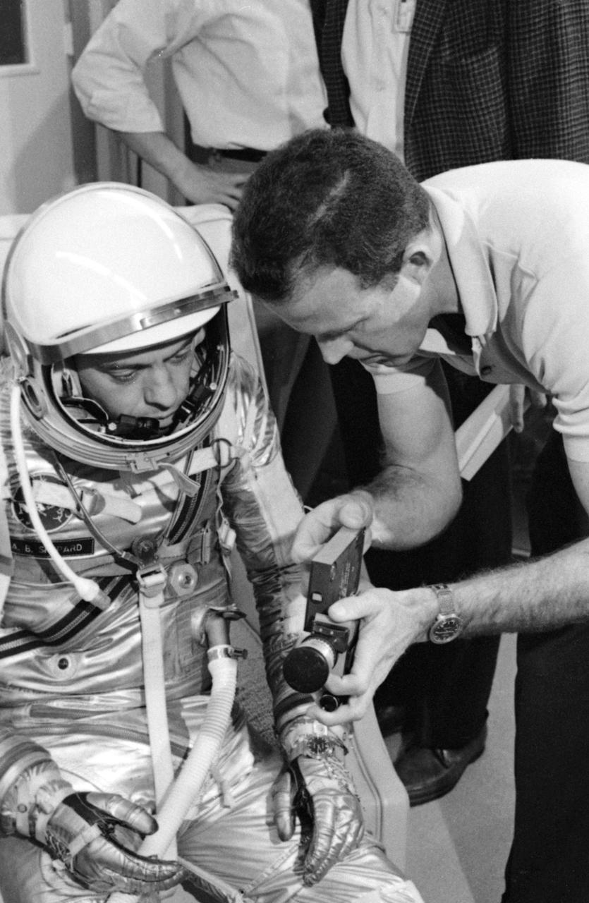
S63-03952 (1963) --- Astronaut L. Gordon Cooper Jr. explains the 16mm handheld spacecraft camera to his backup pilot astronaut Alan Shepard. The camera, designed by J.R. Hereford of McDonnell Aircraft Corp., will be used by Cooper during the Mercury-Atlas 9 (MA-9) mission to photograph experiments in space for M.I.T. and the Weather Bureau. Photo credit: NASA
KSC-84PC-248 (For release Aug. 27, 1984) --- The Continuous Flow Electrophoresis System (CFES) is being installed in the middeck of the Orbiter Discovery in preparation for the flight of mission STS-41D in June. The CFES, originating from the McDonnell Douglas Astronautics Co. includes a fluid systems module, and experiment control and monitoring module, a sample storage module and a pump/accumulator package along with miscellaneous equipment stored in a middeck locker. Photo credit: NASA
S64-25295 (March 1964) --- Astronauts Virgil I. (Gus) Grissom (right) and John W. Young, prime crew for the first manned Gemini mission (GT-3), are shown inside a Gemini mission simulator at McDonnell Aircraft Corp., St. Louis, MO. The simulator will provide Gemini astronauts and ground crews with realistic mission simulation during intensive training prior to actual launch.
S65-57481 (25 Oct. 1965) --- Astronaut James A. Lovell Jr., pilot of the Gemini-7 spaceflight, undergoes weight and balance tests in the Pyrotechnic Installation Building, Merritt Island, Kennedy Space Center. Talking with Lovell are (left to right) Charlie Beaty, McDonnell Aircraft Corporation; Karl Stoien, MAC; NASA suit technician Al Rochferd; and Norm Batterson, Weber Aircraft Corporation. Photo credit: NASA
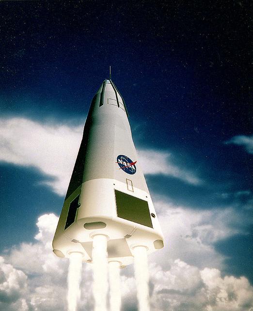
This is the McDornell Douglas CD-XA Reusable Launch Vehicle (RLV) concept. The Delta Clipper-Experimental (DC-X) was originally developed by McDonnell Douglas for the DOD. The DC-XA is a single-stage-to-orbit, vertical takeoff/vertical landing, launch vehicle concept, whose development is geared to significantly reduce launch cost and provided a test bed for NASA Reusable Launch Vehicle (RLV) technology as the Delta Clipper-Experimental Advanced (DC-XA). The program was discontinued in 2003.

A Delta II rocket carrying the Geomagnetic Tail Lab (GEOTAIL) spacecraft lifts off at Launch Complex 17, Kennedy Space Center (KSC) into a cloud-dappled sky. This liftoff marks the first Delta launch under the medium expendable launch vehicle services contract between NASA and McDonnell Douglas Space Systems Co. The GEOTAIL mission, a joint US/Japanese project, is the first in a series of five satellites to study the interactions between the Sun, the Earth's magnetic field, and the Van Allen radiation belts.
S65-21090 (23 March 1965) --- Astronauts Virgil I. Grissom, command pilot; and John W. Young, pilot, wait inside their Gemini-3 spacecraft just after the hatches were closed prior to liftoff. McDonnell Aircraft Corp. technicians can be seen making final adjustments and inspection prior to leaving the white room atop the Titan launch vehicle at Pad 19, Cape Kennedy, Florida. The Gemini-Titan 3 spacecraft is being prepared for launch.
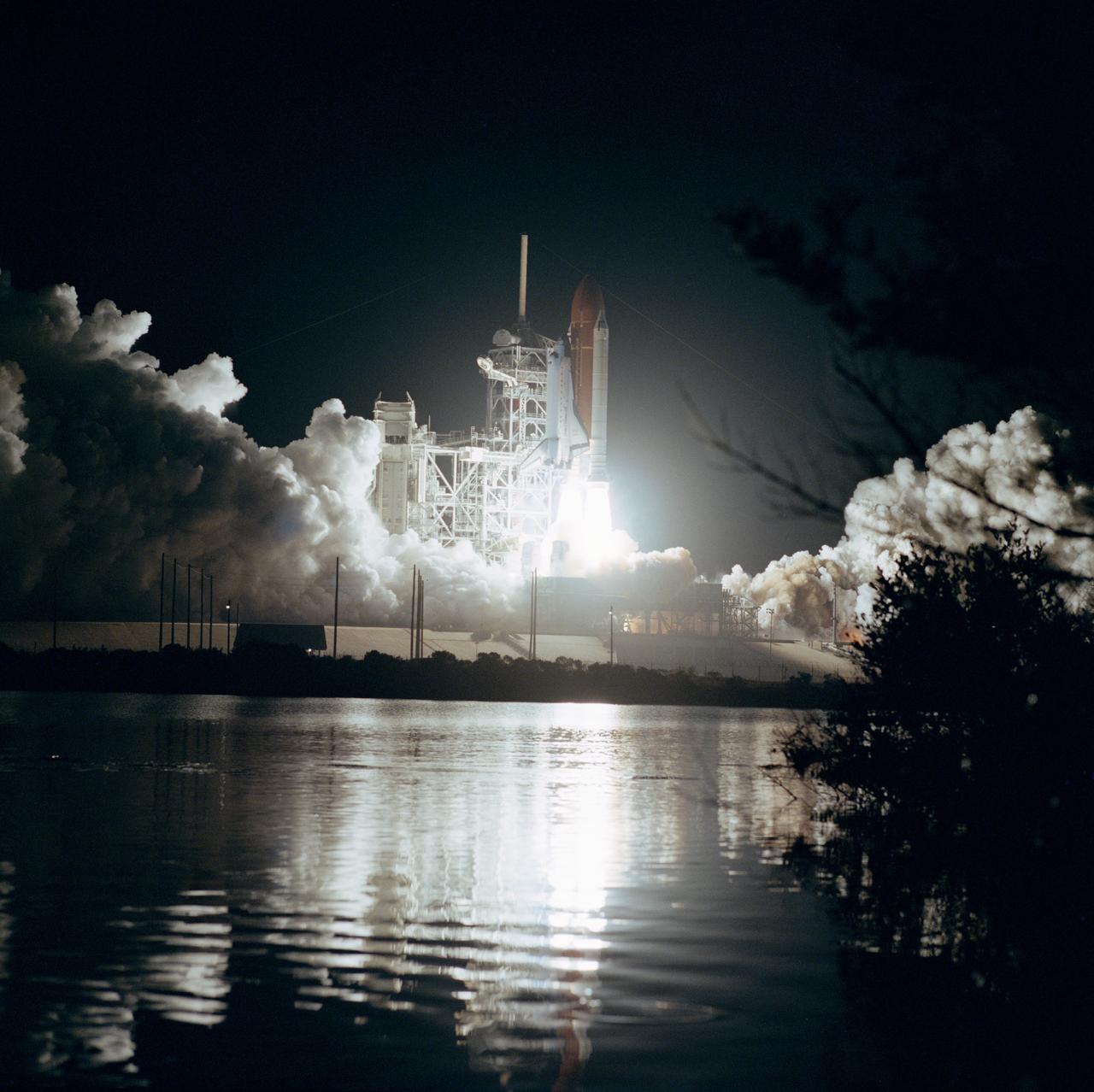
61B-S-067 (26 Nov 1985) --- Space Shuttle Atlantis ascends into the night sky at 7:29 p.m. (EST), November 26, with a seven member crew and three communications satellites aboard. The STS 61-B crewmembers are Brewster Shaw Jr., Bryan D. O?Connor, Mary L. Cleave, Sherwood C. Spring, Jerry L. Ross and Payload Specialists Rodolfo Neri of Mexico (Morelos) and Charles D. Walker of McDonnell Douglas.
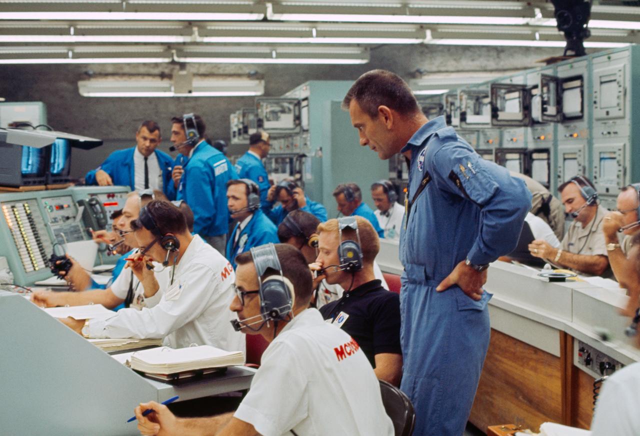
S65-28742 (21 Aug. 1965) --- View of Mission Control Center at Cape Kennedy, Florida, moments after the Gemini-5 spacecraft was launched from Pad 19 on Aug. 21, 1965. Standing at right is astronaut Donald K. Slayton, assistant director for Flight Crew Operations, Manned Spacecraft Center. Seated (wearing dark shirt) is astronaut Russell L. Schweickart. Other NASA and McDonnell Aircraft Col. personnel also monitor the progress of the flight.
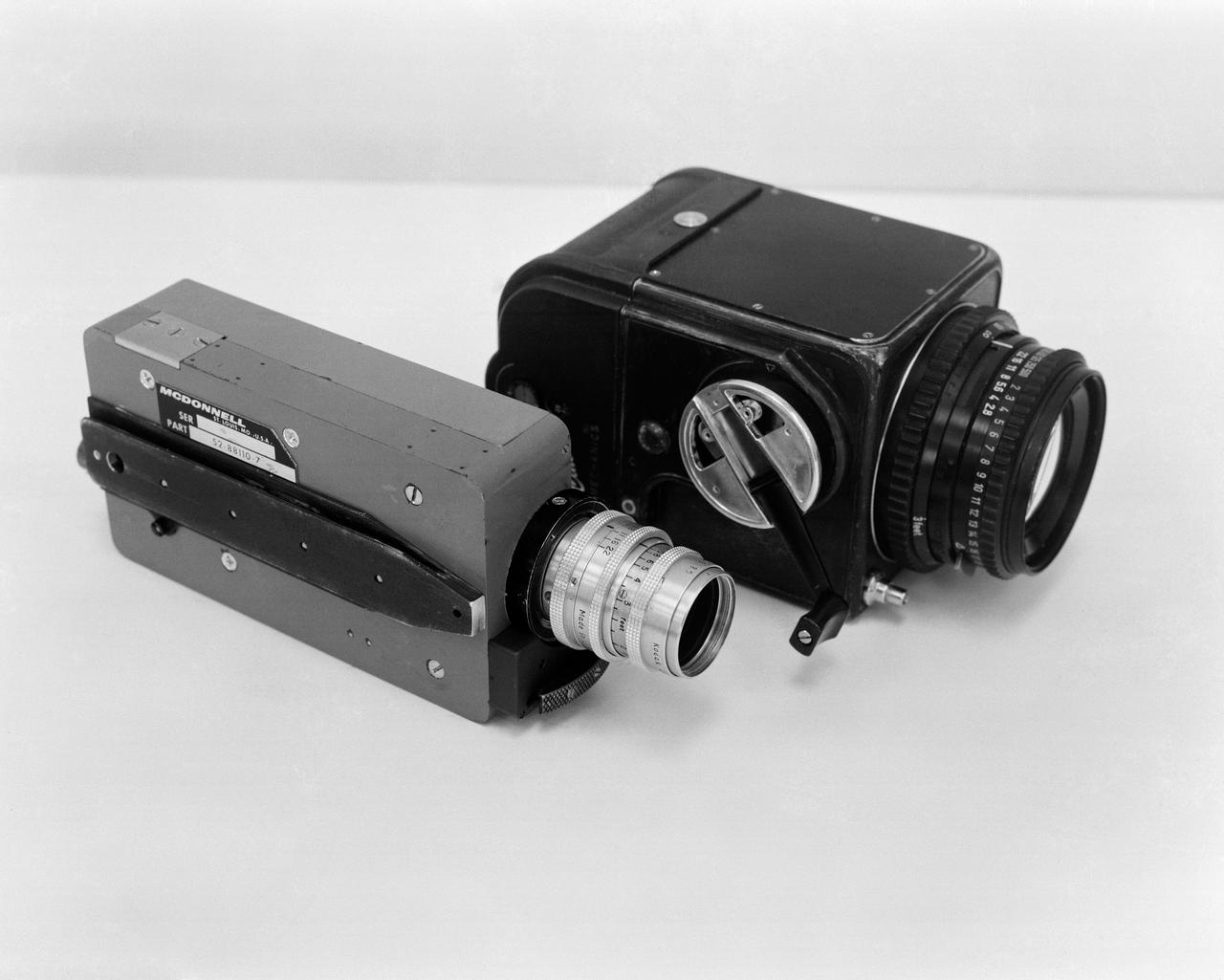
S65-17399 (March 1965) --- Two cameras which will be used on the Gemini-Titan 3 orbital flight. The lighter colored one is a McDonnell 16mm sequential camera, having a 120-feet film capacity, and a 25mm f/1.9 lens. The black camera is a modified Hasselblad, hand-held, with a 70mm flimback, using an 80mm f/2.8 lens.
S63-03960 (1 Feb. 1963) --- Astronaut L. Gordon Cooper Jr., prime pilot for the Mercury-Atlas 9 (MA-9) mission, checks over the instrument panel from Mercury spacecraft #20 with Robert Graham, McDonnell Aircraft Corp. spacecraft engineer. It contains the instruments necessary to monitor spacecraft systems and sequencing, the controls required to initiate primary sequences manually, and flight control displays. Photo credit: NASA
S65-61837 (27 Nov. 1965) --- The Gemini-7 backup crew seen in the White Room atop Pad 19 during Gemini-7 simulation flight activity. McDonnell Aircraft Corporation technicians assist in the exercise. Astronaut Edward H. White II (in foreground) is the Gemini-7 backup crew command pilot; and astronaut Michael Collins (right background) is the backup crew pilot. Photo credit: NASA
S65-59984 (15 Dec. 1965) --- NASA and McDonnell technicians assist the Gemini-6 prime crew into the spacecraft in the white room atop Pad 19 during the Gemini-6 prelaunch countdown at Cape Kennedy, Florida. Astronaut Walter M. Schirra Jr., command pilot, is on the left; and astronaut Thomas P. Stafford, pilot, is on the right. Liftoff was at 8:37 a.m. (EST) on Dec. 15, 1965. Photo credit: NASA or National Aeronautics and Space Administration
S66-33407 (10 May 1966) --- Astronauts Thomas P. Stafford (right foreground), command pilot; and Eugene A. Cernan, pilot, prepare to enter the Gemini-9 spacecraft in the white room atop Pad 19 during a Gemini-9/Agena simultaneous launch demonstration. This test is a coordinated countdown of the Atlas-Agena and the Gemini-Titan vehicles. NASA and McDonnell Aircraft Corporation personnel stand by to assist with the insertion of the astronauts into the spacecraft. Photo credit: NASA
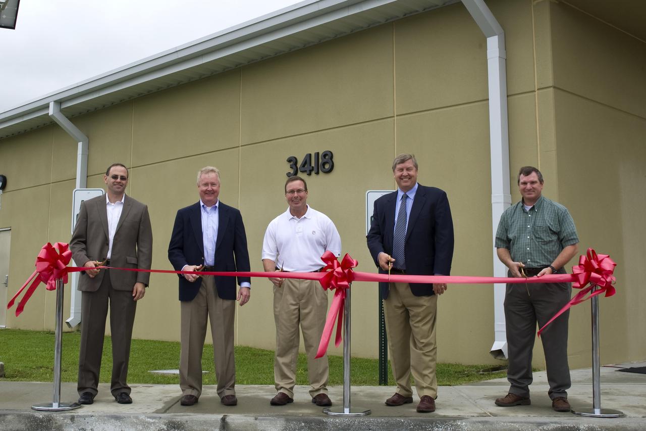
NASA cut the ribbon on a new cryogenics control center at John C. Stennis Space Center on March 30. The new facility is part of a project to strengthen Stennis facilities to withstand the impacts of future storms like hurricane Katrina in 2005. Participants in the ribbon-cutting included (l to r): Jason Zuckerman, director of project management for The McDonnel Group; Keith Brock, director of the NASA Project Directorate at Stennis; Stennis Deputy Director Rick Gilbrech; Steve Jackson, outgoing program manager of the Jacobs Technology NASA Test Operations Group; and Troy Frisbie, Cryo Control Center Construction project manager for NASA Center Operations at Stennis.

Roy D. Bridges Jr., KSC's next center director, at right, poses in the firing room of the Launch Control Center with two top contractor officials at Kennedy Space Center during the STS-82 launch of Discovery on the second Hubble Space Telescope servicing mission. From left, are Michael J. McCulley, vice president and associate program manager for ground operations for United Space Alliance at KSC; and Bruce Melnick, vice president of McDonnell Douglas Space and Defense Systems-KSC. Bridges is slated to become KSC's seventh center director on March 2, succeeding Jay F. Honeycutt
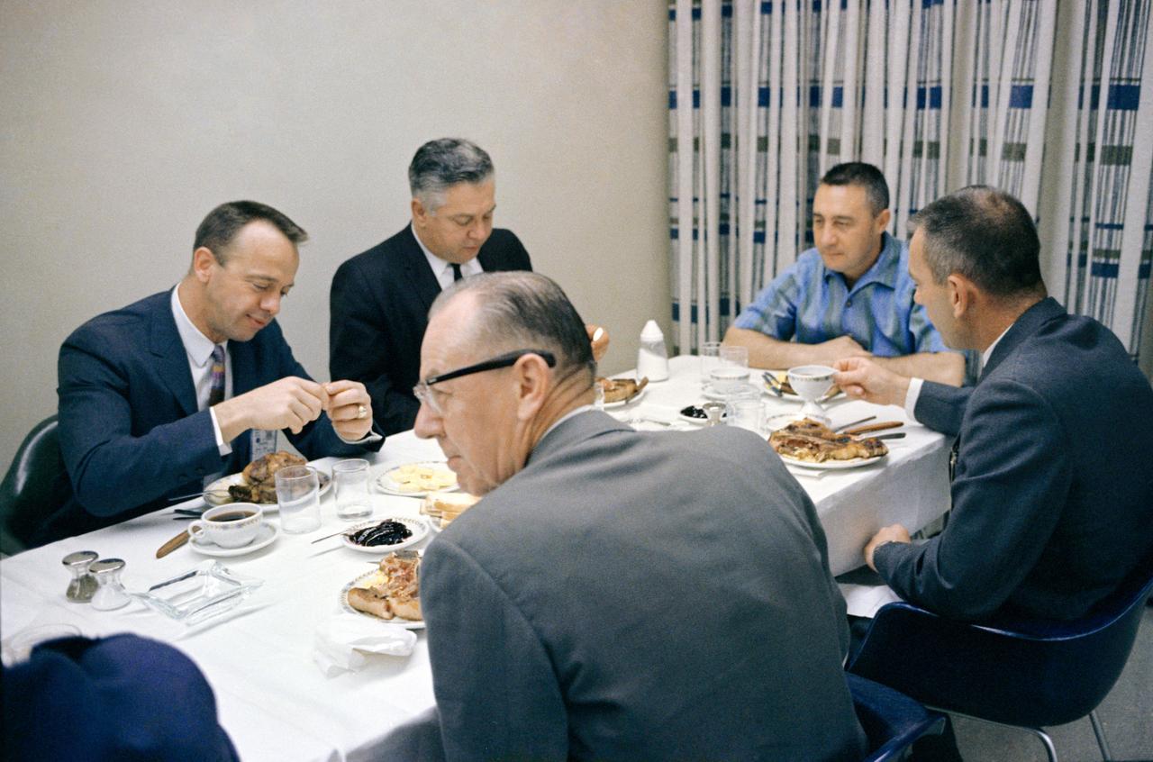
S65-21093 (23 March 1965) --- Astronaut Virgil I. Grissom (facing camera at right), command pilot of the Gemini-Titan 3 flight, is shown during a steak breakfast which he was served about two hours prior to the 9:24 a.m. (EST) GT-3 launch on March 23, 1965. Pictured in the foreground are Donald K. Slayton (right), assistant director for Flight Crew Operations; and Walter Burke, general manager of McDonnell Aircraft Corporation Spacecraft and Missiles. Pictured in the background are astronaut Alan B. Shepard Jr. (left) and Walter C. Williams, former deputy director of the Manned Spacecraft Center, now with a private aerospace firm.
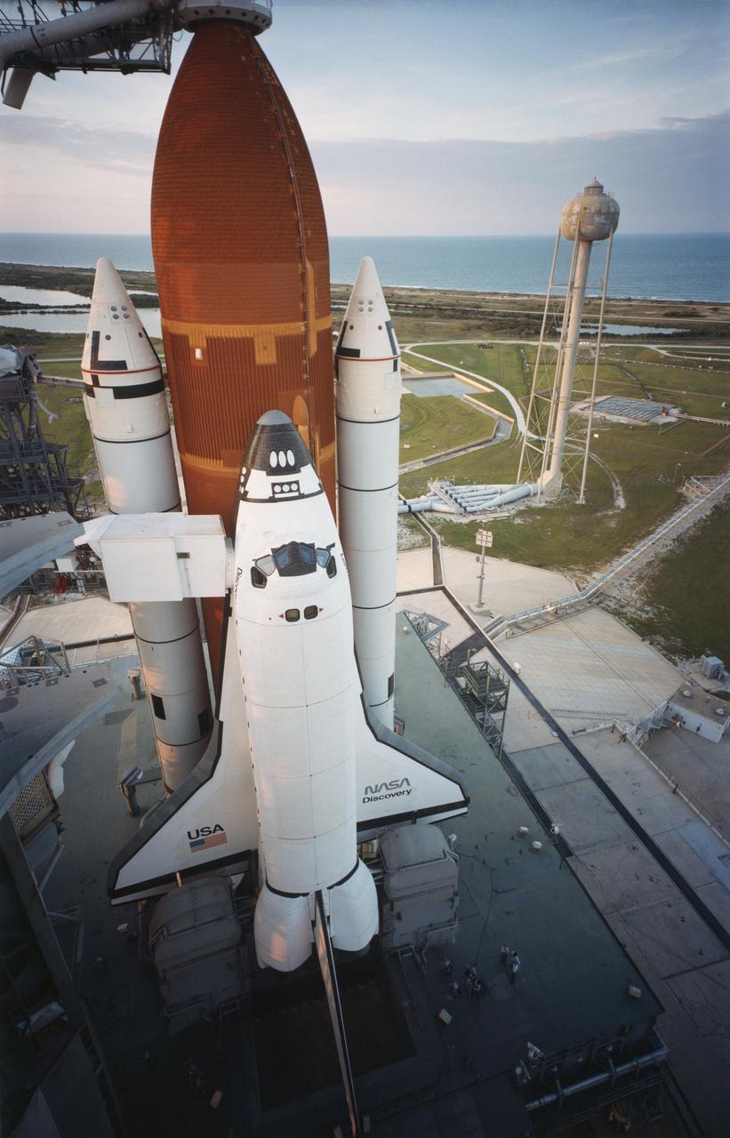
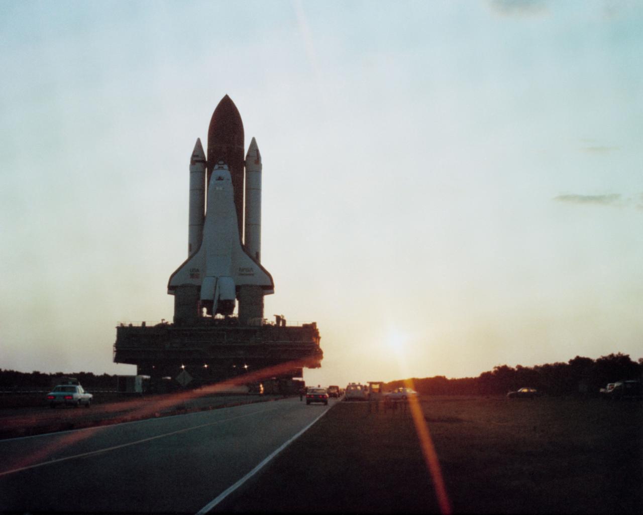
KSC-84PC-476 (For release Aug. 29, 1984) --- Orbiter Discovery is poised on Launch Pad 39A as the sun sets the evening prior to its maiden launch. Space shuttle Discovery (STS-41D) was successfully launched at 8:41 a.m. Aug. 30, 1984, after two failed attempts in June. Carrying a crew of six astronauts and three satellites, Discovery is the third in NASA?s stable of four Space Transportation System orbiters. The six-person crew includes Commander Henry Hartsfield, Pilot Michael Coats, Mission Specialists Judith Resnik, Mike Mullane and Steve Hawley and the first commercial payload specialist, Charles Walker of McDonnell Douglas. Photo credit: NASA

NASA cut the ribbon on a new cryogenics control center at John C. Stennis Space Center on March 30. The new facility is part of a project to strengthen Stennis facilities to withstand the impacts of future storms like hurricane Katrina in 2005. Participants in the ribbon-cutting included (l to r): Jason Zuckerman, director of project management for The McDonnel Group; Keith Brock, director of the NASA Project Directorate at Stennis; Stennis Deputy Director Rick Gilbrech; Steve Jackson of Jacobs Technology; and Troy Frisbie, Cryo Control Center Construction project manager for NASA Center Operations at Stennis.
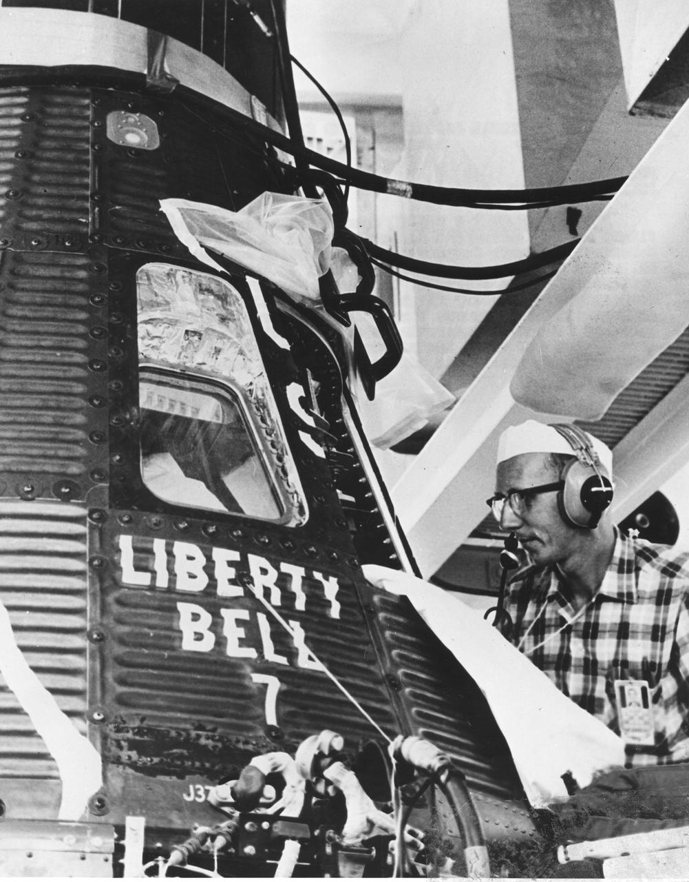
KENNEDY SPACE CENTER, FLA. -- PROJECT MERCURY'S SECOND suborbital astronaut training flight will be attempted during the week of July 16 with McDonnell Aircraft Corporation's production spacecraft number 11, which has been named 'Liberty Bell 7.' The number seven stresses the team effort of the seven Mercury pilots necessary for conducting Mercury flights. Mission pilot for the MR-4 launch will be astronaut Virgil I. 'Gus' Grissom. His spacecraft is seen here undergoing systems checks in the National Aeronautics and Space Administration's Mercury Hangar at Cape Canaveral, Florida, weeks before the planned launch
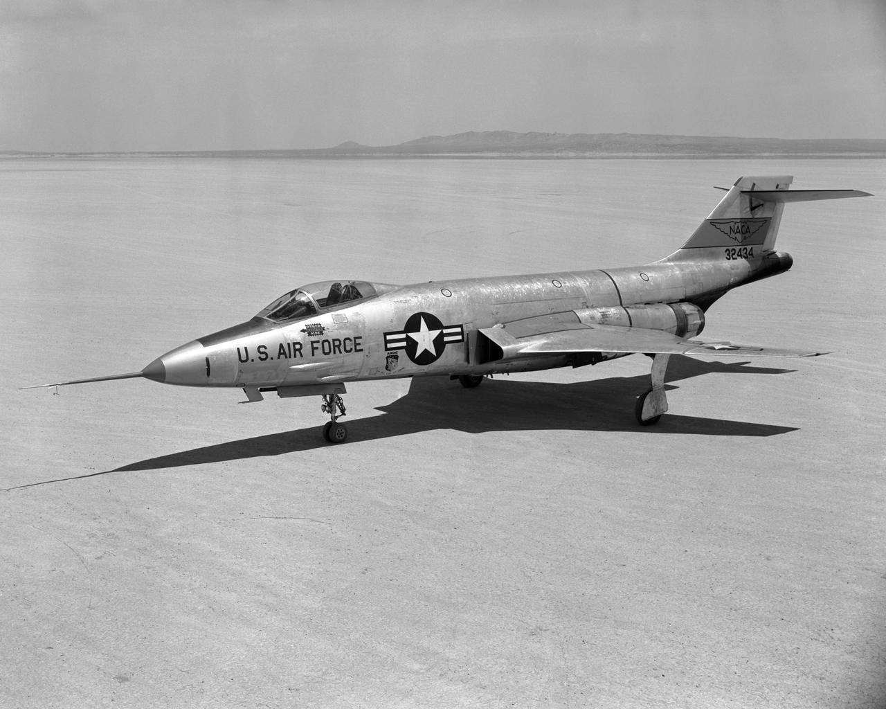
F-101A Front quarter view on Edwards Lakebed Aug. 10, 1956
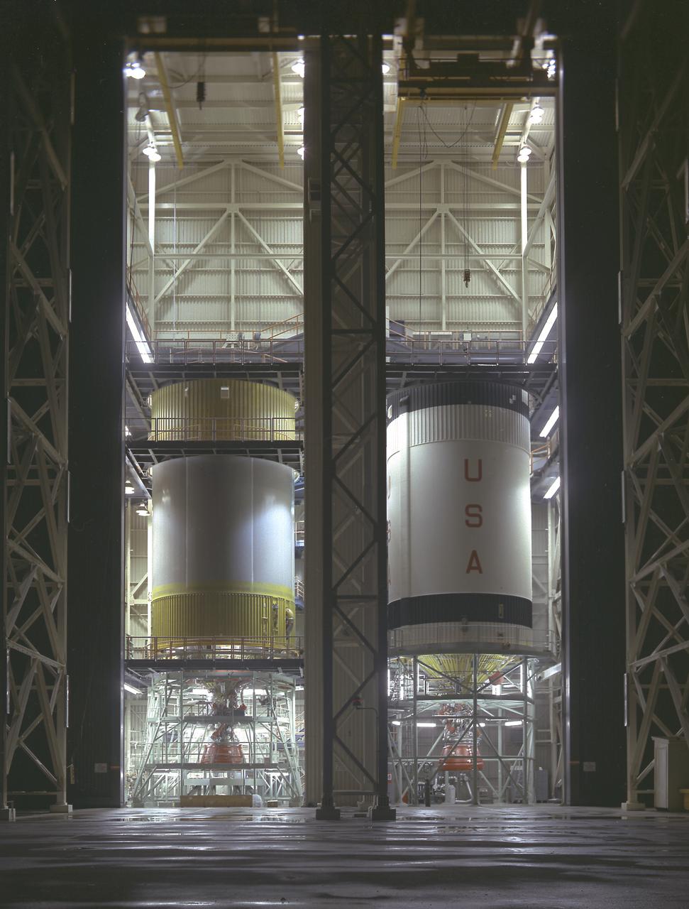
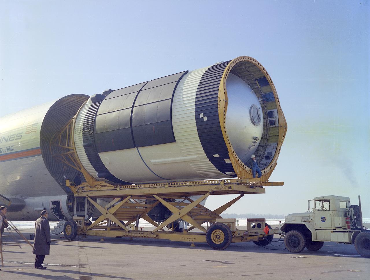
S-IVB-505 and S-IVB-211, the flight version of the S-IVB stages, in the McDornell Douglas' S-IVB Assembly and Checkout Tower in Huntington Beach, California. As a part of the Marshall Space Flight Center `s "building block" approach to the Saturn vehicle development, the S-IVB stage, in its 200 series, was utilized as the Saturn IB launch vehicle's second stage, and, in its 500 series, the Saturn V's third stage. The S-IVB was powered by a single J-2 engine, initially capable of 200,000 pounds of thrust.
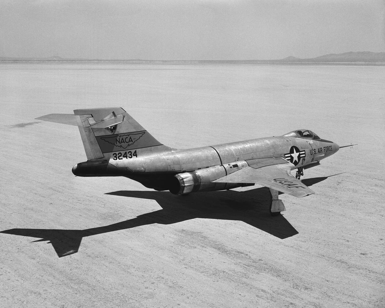
F-101A Rear quarter view on Edwards Lakebed. Aug. 10, 1956
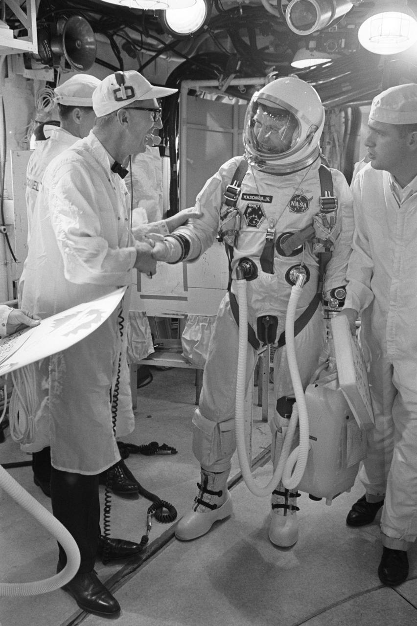
S65-61912 (12 Dec. 1965) --- Astronaut Walter M. Schirra Jr., command pilot, accepts the best wishes of G.F. Wendt, McDonnell Aircraft Corporation pad leader, as he arrives in the white room atop Pad 19. Moments later, Schirra and astronaut Thomas P. Stafford, pilot, entered the spacecraft for their planned two-day mission. At right is NASA suit technician Al Rochford. NASA attempted to launch Gemini-6 at 9:54 a.m. (EST) on Dec. 12, 1965. However, seconds after ignition the first stage engine of the Gemini-6 launch vehicle shut down due to a faulty release of a liftoff umbilical plug. Photo credit: NASA or National Aeronautics and Space Administration

S85-28647 (28 Feb 1985) --- The seven members of the STS-51D mission are pictured in the midst of a busy training schedule in preparation for NASA's 16th Space Shuttle flight, currently planned for April of this year. The crewmembers are (front row, left to right), Karol J. Bobko, commander; Donald E. Williams, pilot; Rhea Seddon and Jeffrey A. Hoffman, mission specialists; and (back row) S. David Griggs, mission specialist; and Charles D. Walker and United States Senator Jake Garn (Republican - Utah) both payload specialists. Walker represents McDonnell-Douglas Corporation. EDITOR'S NOTE: Mission specialist S. David Griggs died June 17, 1989, near Earle, Arkansas, in the crash of a World-War-II-era training plane.
KENNEDY SPACE CENTER, FLA. -- McDonnell Douglas-SPACEHAB technicians prepare to place a Russian-made oxygen generator into position for transport in a SPACEHAB Double Module being processed for flight on Space Shuttle Mission STS-84. The module is undergoing preflight preparations in the SPACEHAB Payload Processing Facility just outside of Gate 1 on Cape Canaveral Air Station. The Space Shuttle Atlantis will carry the oxygen generator to the Russian Space Station Mir to replace one of two Mir units that have been malfunctioning recently. The nearly 300-pound generator functions by electrolysis, which separates water into its oxygen and hydrogen components. The hydrogen is vented and the oxygen is used for breathing by the Mir crew. The generator is 4.2 feet long with a diameter of 1.4 feet. STS-84, which is planned to include a Mir crew exchange of astronaut C. Michael Foale for Jerry M. Linenger, is targeted for a May 15 launch. It will be the sixth Shuttle-Mir docking
This photograph was taken at the Redstone airfield, Huntsville, Alabama, during the unloading of the Saturn V S-IVB stage that housed the Orbital Workshop (OWS) from the Super Guppy, the NASA plane that was specially built to carry oversized cargo. The OWS measured 22 feet (6.7 m) in diameter, and 48 feet (14.6 m) in length. The Saturn V S-IVB stage was modified at the McDornell Douglas facility at Huntington Beach, California, for a new role, which was to house the OWS. In addition to the test articles, engineering mockups, and flight equipment, both McDonnell Douglas and Martin Marietta built 0-G trainers, neutral buoyancy trainers, and high-fidelity mockups for the 1-G trainer to be used in the KC-135 aircraft. The Marshall Space Flight Center had program management responsibility for the development of Skylab hardware and experiments.
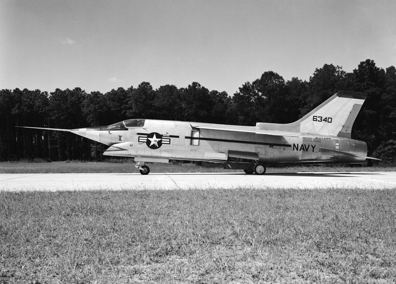
Crusader on runway. Navy aircraft number 6340. L59-6101 caption: The Navy's Vought XF8U-3 Supersonic Fighter was an entirely new design as compared to the earlier F8U Crusader series. This jet plane lost in competition with the McDonnell F4H, however, and was never put into production. Langley used the XF8U-3 in some of the first flight measurements of sonic boom intensity. Photograph published in Engineer in Charge A History of the Langley Aeronautical Laboratory, 1917-1958 by James R. Hansen. Page 507. Caption: Chance Vought F8U-3 airplane used in sonic boom investigation at Wallops, June-August 1959. Photograph published in A New Dimension Wallops Island Flight Test Range: The First Fifteen Years by Joseph Shortal. A NASA publication. Page 672.
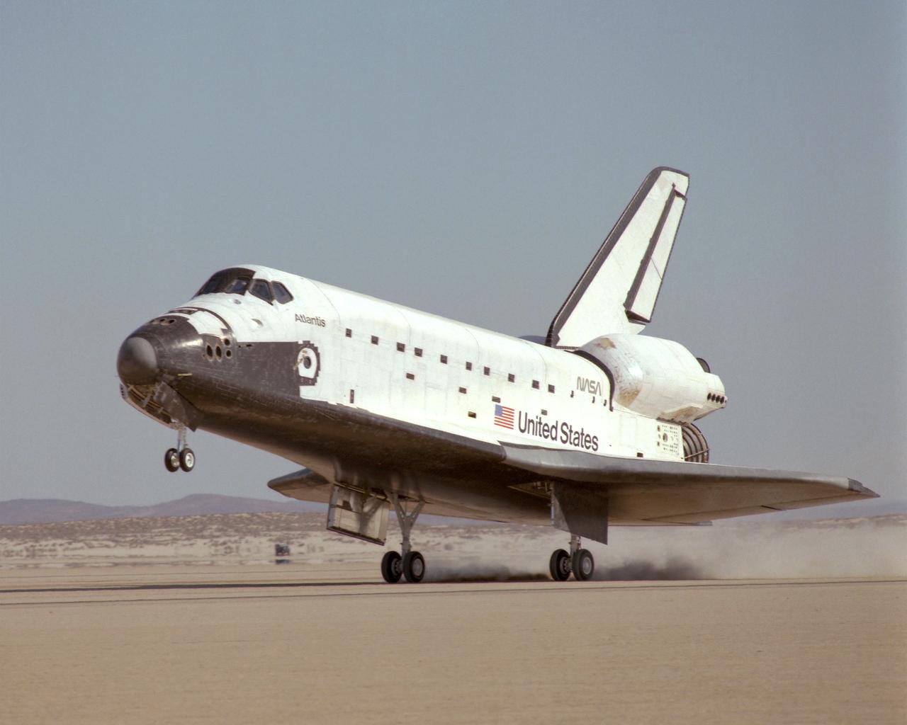
NASA's Space Shuttle Atlantis touched down on the lakebed runway at Edwards Air Force Base in California's Mojave Desert Tuesday, 3 December 1985 at 1:33:49 p.m. Pacific Standard Time, concluding the STS 61-B international mission. The eight-day mission successfully deployed three communications satellites including the Mexican Morelos B, the Australian Aussat 2 and an RCA Satcom K-2 satellite. In addition, two spacewalks were performed to experiment with construction of structures in space. Crew of the 61-B mission included Commander Brewster H. Shaw, Jr.; Pilot Bryan D. O'Connor; Mission Specialists Mary L. Cleave, Sherwood C. Spring and Jerry L. Ross; and Payload Specialists Rudolfo Neri Vela of Mexico and Charles Walker of McDonnell Douglas Astronautics Co.
S86-41700 (19 May 1984) --- The Space Shuttle Discovery moves towards Pad A on the crawler transporter for its maiden flight. Discovery will be launched on its first mission no earlier than June 19, 1984. Flight 41-D will carry a crew of six; Commander Henry Hartsfield, Pilot Mike Coats, Mission Specialists Dr. Judith Resnik, Dr. Steven Hawley and Richard Mullane and Payload Specialist Charles Walker. Walker is the first payload specialist to fly aboard a space shuttle. He will be running the materials processing device developed by McDonnell Douglas as part of its Electrophoresis Operations in Space project. Mission 41-D is scheduled to be a seven-day flight and to land at Edwards Air Force Base in California. The Syncom IV-1 (LEASAT) will be deployed from Discovery's cargo bay and the OAST-1, Large Format Camera, IMAX and Cinema 360 cameras will be aboard.

McDonnell Douglas-SPACEHAB technicians oversee the move of a Russian-made oxygen generator to a SPACEHAB Double Module, at rear, in the SPACEHAB Payload Processing Facility. In foreground, from left, are Marc Tuttle, Dan Porter and Mike Vawter. The oxygen generator, manufactured in Russia by RSC Energia, will be carried aboard the Space Shuttle Atlantis on Mission STS-84 for the Shuttle’s scheduled docking with the Russian Space Station Mir next month. The nearly 300-pound generator will replace one of two Mir units that have been malfunctioning recently. The generator functions by electrolysis, which separates water into its oxygen and hydrogen components. The hydrogen is vented and the oxygen is used for breathing by the Mir crew. The generator is 4.2 feet in length and 1.4 feet in diameter. STS-84, which is planned to include a Mir crew exchange of astronaut C. Michael Foale for Jerry M. Linenger, is targeted for a May 15 liftoff
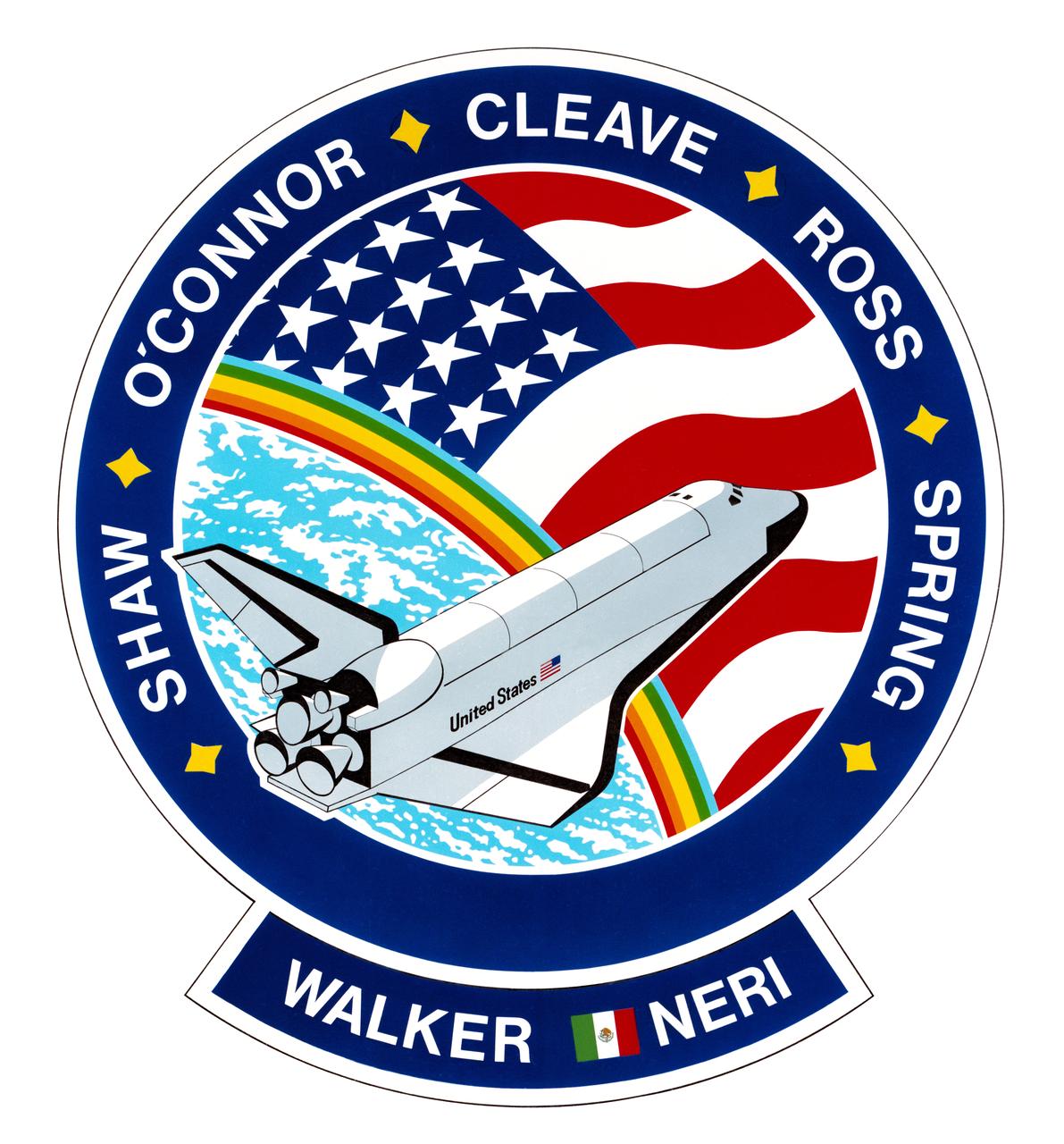
S85-36635 (October 1985) --- This is the insignia designed by the STS-61B crew members to represent their November 1985 mission aboard the space shuttle Atlantis, depicted here in Earth orbit, making only its second spaceflight. The design is surrounded by the surnames of the seven crew members. They are astronauts Brewster Shaw Jr., commander; Bryan D. O'Conner, pilot; Mary L. Cleave, Jerry L. Ross and Sherwood C. Spring, all mission specialists; and payload specialists Charles D. Walker, representing McDonnell Douglas, and Rodolfo Neri, representing Morelos of Mexico (note flag). The NASA insignia design for space shuttle flights is reserved for use by the astronauts and for other official use as the NASA Administrator may authorize. Public availability has been approved only in the forms of illustrations by the various news media. When and if there is any change in this policy, which is not anticipated, the change will be publicly announced. Photo credit: NASA
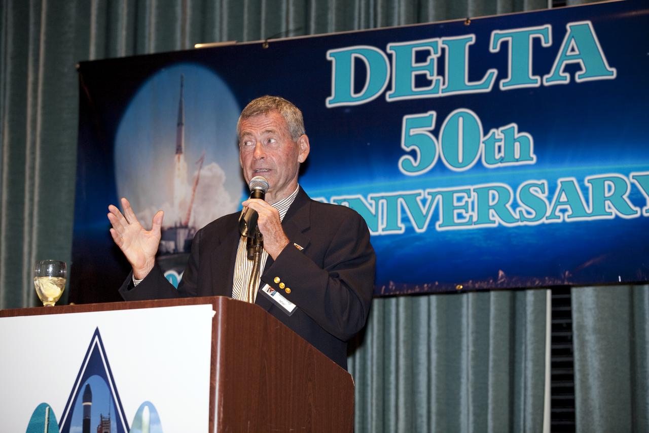
CAPE CANAVERAL, Fla. - Lyle Holloway, former director of launch sites originally for McDonnell Douglas, helps NASA, the U.S. Air Force, United Launch Alliance, Boeing, Pratt and Whitney Rocketdyne, Aerojet and the NASA Alumni League celebrate the Delta expendable launch vehicle program's 50th anniversary at the Radisson Resort in Cape Canaveral, Fla., on May 16. NASA launched the first Delta rocket, which only was intended to be an interim launch vehicle, on May 13, 1960. A half-century later, more than 300 Delta rockets have launched to place crucial weather and environmental satellites into Earth orbit. The vehicles also have sent spacecraft on missions to other planets and comets, and to study the universe. Currently, the Delta II and Delta IV are in use by NASA's Launch Services Program based at Kennedy Space Center in Florida, and are launched by United Launch Alliance. Photo credit: NASA_Amanda Diller
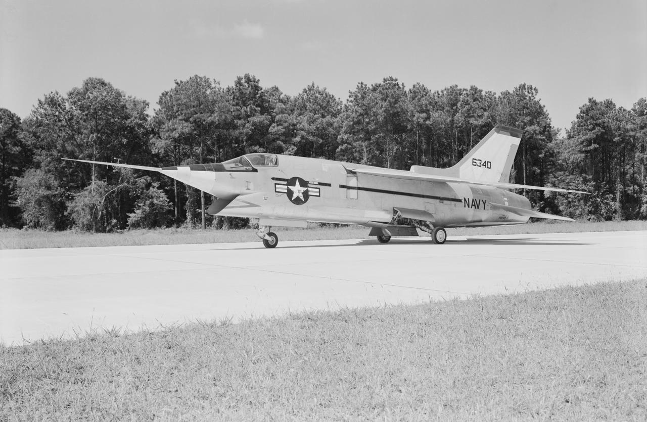
Crusader on runway. Navy aircraft number 6340. L59-6101 caption: The Navy's Vought XF8U-3 Supersonic Fighter was an entirely new design as compared to the earlier F8U Crusader series. This jet plane lost in competition with the McDonnell F4H, however, and was never put into production. Langley used the XF8U-3 in some of the first flight measurements of sonic boom intensity. Photograph published in Engineer in Charge A History of the Langley Aeronautical Laboratory, 1917-1958 by James R. Hansen. Page 507. Caption: Chance Vought F8U-3 airplane used in sonic boom investigation at Wallops, June-August 1959. Photograph published in A New Dimension Wallops Island Flight Test Range: The First Fifteen Years by Joseph Shortal. A NASA publication. Page 672.
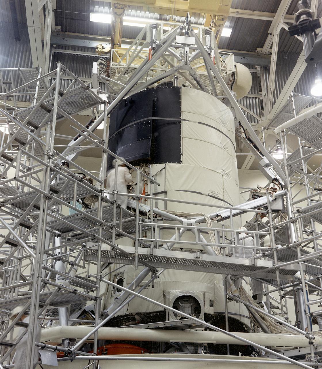
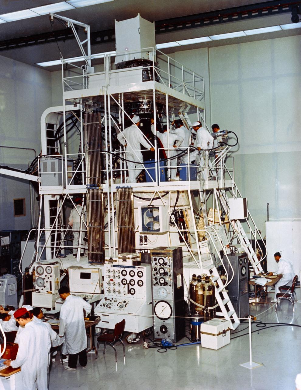
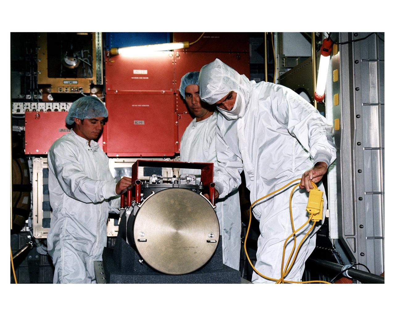
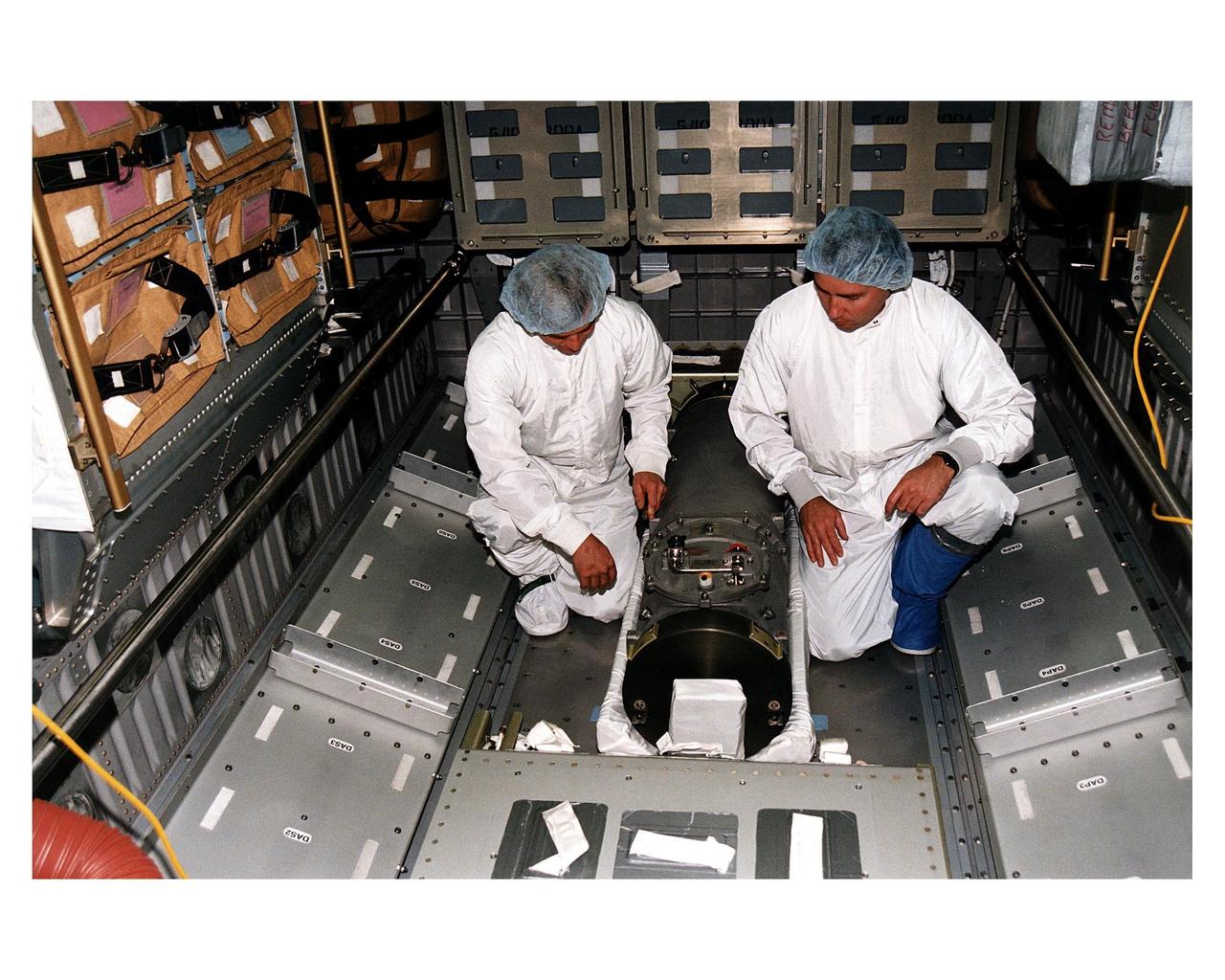
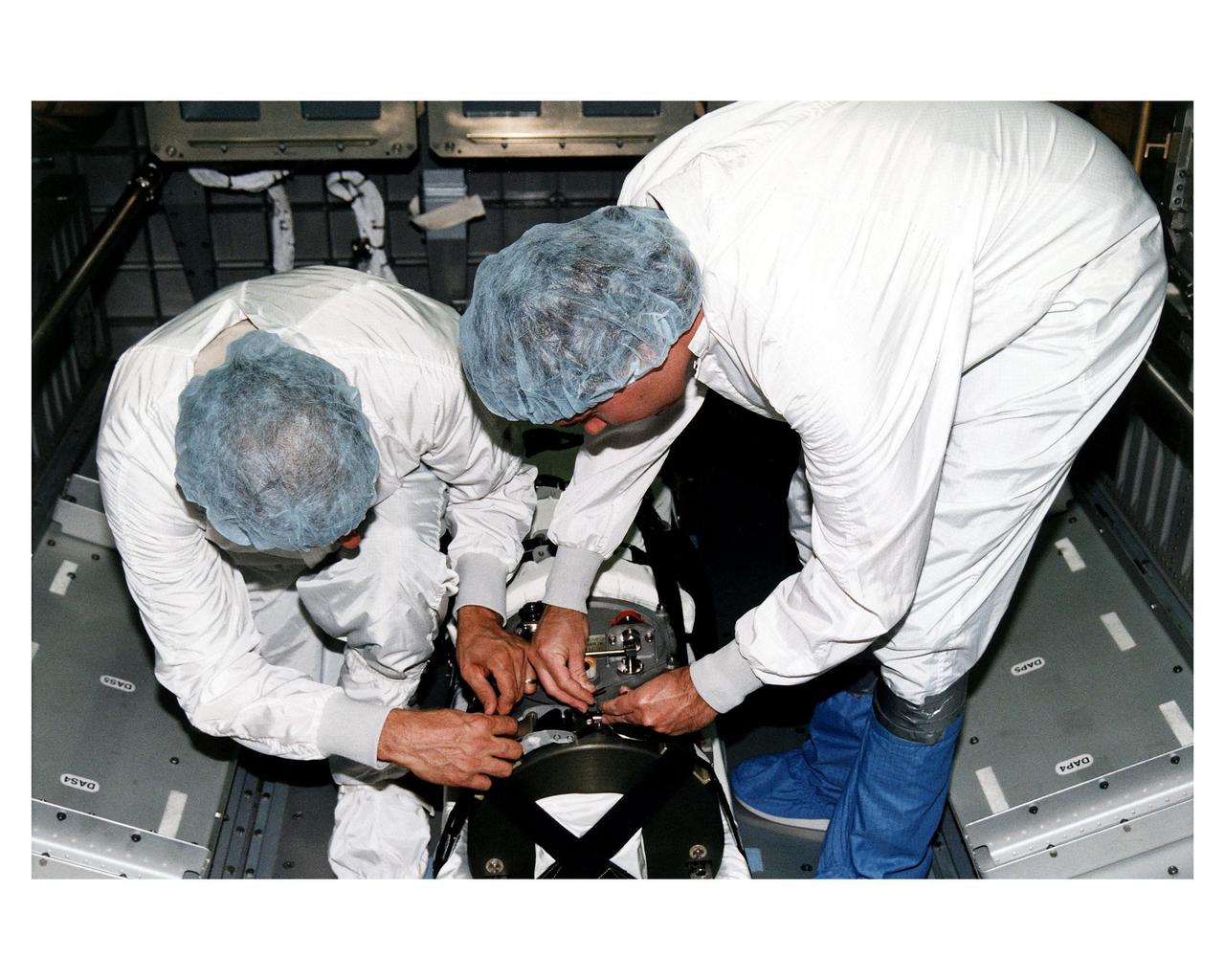
This photograph shows the flight article of the Airlock Module (AM)/Multiple Docking Adapter (MDA) assembly being readied for testing in a clean room at the McDornell Douglas Plant in St. Louis, Missouri. Although the AM and the MDA were separate entities, they were in many respects simply two components of a single module. The AM enabled crew members to conduct extravehicular activities outside Skylab as required for experiment support. Oxygen and nitrogen storage tanks needed for Skylab's life support system were mounted on the external truss work of the AM. Major components in the AM included Skylab's electric power control and distribution station, environmental control system, communication system, and data handling and recording systems. The MDA, forward of the AM, provided docking facilities for the Command and Service Module. It also accommodated several experiment systems, among them the Earth Resource Experiment Package, the materials processing facility, and the control and display console needed for the Apollo Telescope Mount solar astronomy studies. The AM was built by McDonnell Douglas and the MDA was built by Martin Marietta. The Marshall Space Flight Center was responsible for the design and development of the Skylab hardware and experiment management.

This is an illustration of the Space Base concept. In-house work of the Marshall Space Flight Center, as well as a Phase B contract with the McDornel Douglas Astronautics Company, resulted in a preliminary design for a space station in 1969 and l970. The Marshall-McDonnel Douglas approach envisioned the use of two common modules as the core configuration of a 12-man space station. Each common module was 33 feet in diameter and 40 feet in length and provided the building blocks, not only for the space station, but also for a 50-man space base. Coupled together, the two modules would form a four-deck facility: two decks for laboratories and two decks for operations and living quarters. Zero-gravity would be the normal mode of operation, although the station would have an artificial-gravity capability. This general-purpose orbital facility was to provide wide-ranging research capabilities. The design of the facility was driven by the need to accommodate a broad spectrum of activities in support of astronomy, astrophysics, aerospace medicine, biology, materials processing, space physics, and space manufacturing. To serve the needs of Earth observations, the station was to be placed in a 242-nautical-mile orbit at a 55-degree inclination. An Intermediate-21 vehicle (comprised of Saturn S-IC and S-II stages) would have launched the station in 1977.
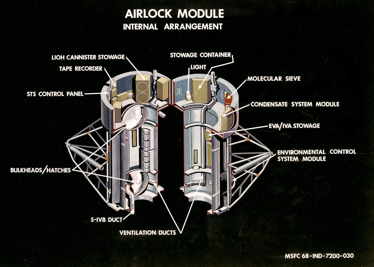
This illustration is a cutaway view of the internal arrangement of the Airlock Module (AM). The aft end of the Docking Adapter mated to the AM, and served as the environmental, electrical, and communications control center. The docking adapter also contained the port through which the astronauts exited to perform extravehicular activity. The AM contained a turnel section through which Skylab crewmen could move between the workshop and the forward end of the airlock. It was encircled, for part of its length, at its aft end by the fixed Airlock Shroud (FAS), that had the same diameter as the workshop (22 feet) and was attached to the workshop's forward end. High pressure containers for oxygen and nitrogen providing Skylab's atmosphere, were mounted in the annular space between the outside of the tunnel and the inside of the shroud. The forward end of the FAS was the base on which the tubular structure supporting the solar observatory was mounted. Many of the supplies, and most of the control systems for Skylab were located in the AM; this module could well be the "utility center" of the Skylab cluster. McDonnell Douglas fabricated the module with close Marshall Space Flight Center's involvement in design, development, and test activities.
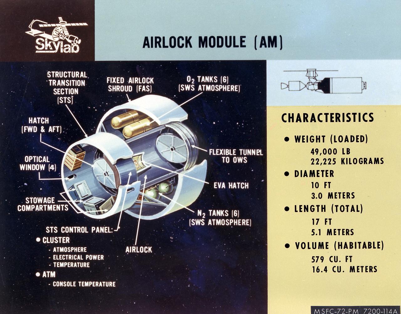
This artist's concept is a cutaway illustration of the Skylab Airlock Module and its characteristics. The aft end of the Docking Adapter mated to the Airlock Module (AM), and served as the environmental, electrical, and communications control center. The docking adapter also contained the port through which the astronauts exited to perform extravehicular activity. The AM contained a turnel section through which Skylab crewmen could move between the workshop and the forward end of the airlock. It was encircled, for part of its length, at its aft end by the fixed Airlock Shroud (FAS), that had the same diameter as the workshop (22 feet) and was attached to the workshop's forward end. High pressure containers for oxygen and nitrogen providing Skylab's atmosphere, were mounted in the annular space between the outside of the tunnel and the inside of the shroud. The forward end of the FAS was the base on which the tubular structure supporting the solar observatory was mounted. Many of the supplies, and most of the control systems for Skylab were located in the AM; this module could well be the "utility center" of the Skylab cluster. McDonnell Douglas fabricated the module with close Marshall Space Flight Center's involvement in design, development, and test activities.
KENNEDY SPACE CENTER, FLA. -- McDonnell Douglas-SPACEHAB technicians look over a Russian-made oxygen generator which has just been placed on the floor of a SPACEHAB Double Module being prepared for flight on Space Shuttle Mission STS-84. The module is being processed in the SPACEHAB Payload Processing Facility just outside of Gate 1 on Cape Canaveral Air Station. The Space Shuttle Atlantis will transport the oxygen generator to the Russian Space Station Mir to replace one of two Mir units that have been malfunctioning recently. The nearly 300-pound generator functions by electrolysis, which separates water into its oxygen and hydrogen components. The hydrogen is vented and the oxygen is used for breathing by the Mir crew. The generator is 4.2 feet long with a diameter of 1.4 feet. STS-84, which is planned to include a Mir crew exchange of astronaut C. Michael Foale for Jerry M. Linenger, is targeted for a May 15 launch. It will be the sixth Shuttle-Mir docking
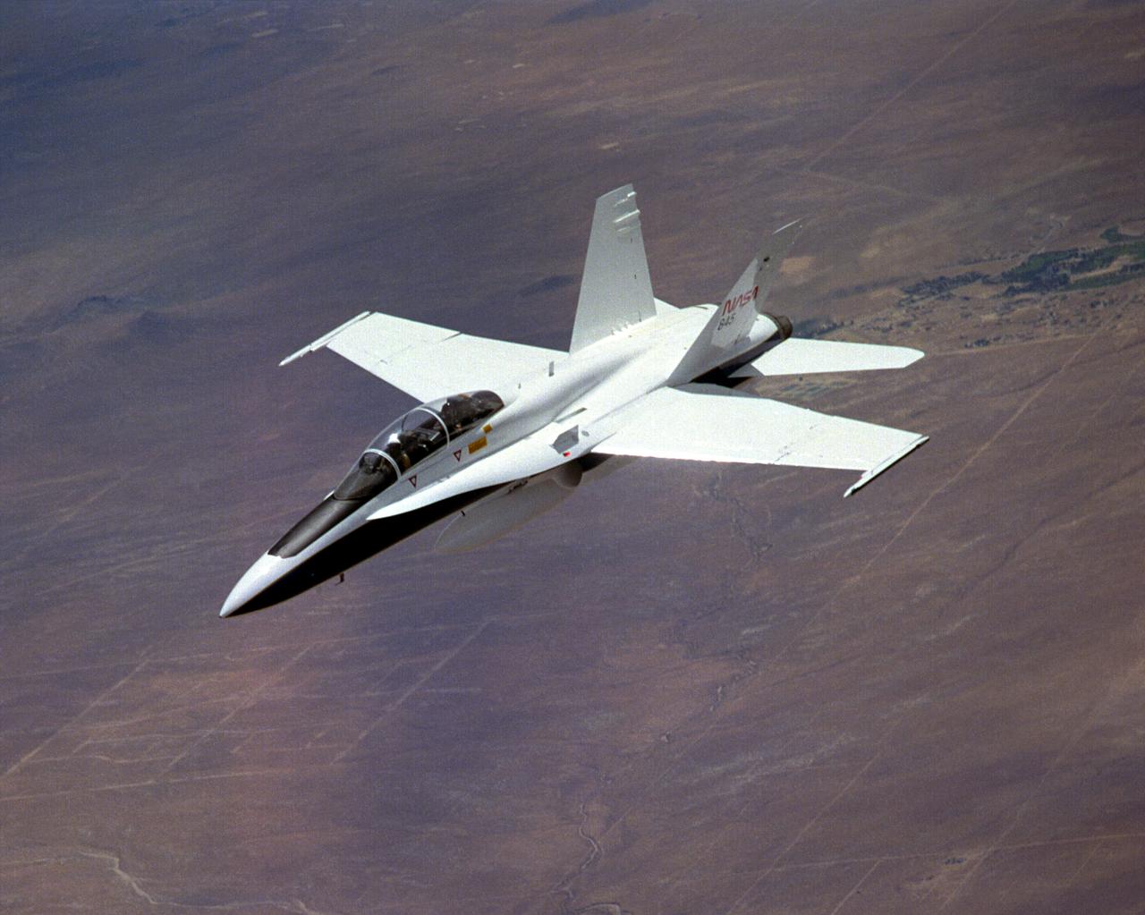
The National Aeronautics and Space Administration's Systems Research Aircraft (SRA), a highly modified F-18 jet fighter, during a research flight. The former Navy aircraft was flown by NASA's Dryden Flight Research Center at Edwards Air Force Base, California, to evaluate a number of experimental aerospace technologies in a multi-year, joint NASA/DOD/industry program. Among the more than 20 experiments flight-tested were several involving fiber optic sensor systems. Experiments developed by McDonnell-Douglas and Lockheed-Martin centered on installation and maintenace techniques for various types of fiber-optic hardware proposed for use in military and commercial aircraft, while a Parker-Hannifin experiment focused in alternative fiber-optic designs for position measurement sensors as well as operational experience in handling optical sensor systems. Other experiments flown on this testbed aircraft included electronically-controlled control surface actuators, flush air data collection systems, "smart" skin antennae and laser-based systems. Incorporation of one or more of these technologies in future aircraft and spacecraft could result in signifigant savings in weight, maintenance and overall cost.
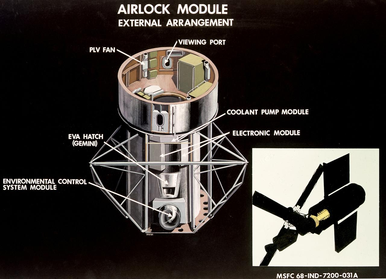
This illustration is a cutaway view of the external arrangement of the Airlock Module (AM). The aft end of the Docking Adapter mated to the AM, and served as the environmental, electrical, and communications control center. The docking adapter also contained the port through which the astronauts exited to perform extravehicular activity. The AM contained a turnel section through which Skylab crewmen could move between the workshop and the forward end of the airlock. It was encircled, for part of its length, at its aft end by the fixed Airlock Shroud (FAS), that had the same diameter as the workshop (22 feet) and was attached to the workshop's forward end. High pressure containers for oxygen and nitrogen providing Skylab's atmosphere, were mounted in the annular space between the outside of the tunnel and the inside of the shroud. The forward end of the FAS was the base on which the tubular structure supporting the solar observatory was mounted. Many of the supplies, and most of the control systems for Skylab were located in the AM; this module could well be the "utility center" of the Skylab cluster. McDonnell Douglas fabricated the module with close Marshall Space Flight Center's involvement in design, development, and test activities.
KENNEDY SPACE CENTER, FLA. -- McDonnell Douglas-SPACEHAB technicians strap in place a Russian-made oxygen generator on the floor of a SPACEHAB Double Module, being prepared for flight in the SPACEHAB Payload Processing Facility. From left, are Mark Halavin and Marc Tuttle. The oxygen generator, manufactured in Russia by RSC Energia, will be carried aboard the Space Shuttle Atlantis on Mission STS-84 for the Shuttle’s scheduled docking with the Russian Space Station Mir next month. The nearly 300-pound generator will replace one of two Mir units that have been malfunctioning recently. The generator functions by electrolysis, which separates water into its oxygen and hydrogen components. The hydrogen is vented and the oxygen is used for breathing by the Mir crew. The generator is 4.2 feet in length and 1.4 feet in diameter. STS-84, which is planned to include a Mir crew exchange of astronaut C. Michael Foale for Jerry M. Linenger, is targeted for a May 15 liftoff. It will be the sixth Shuttle-Mir docking
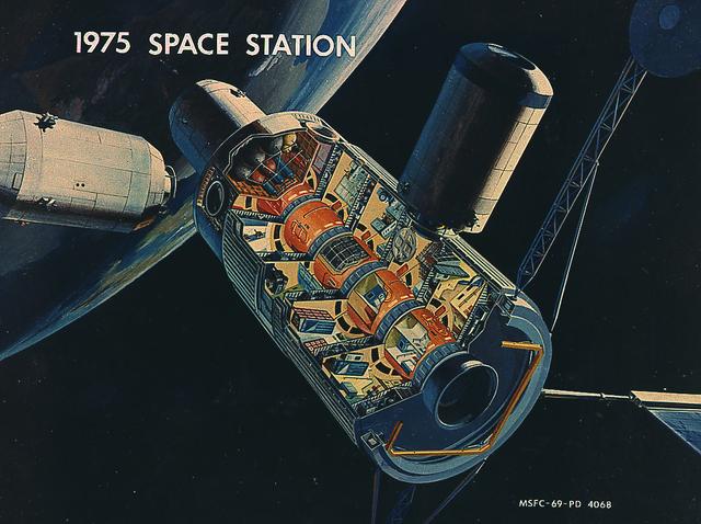
This picture illustrates a concept of a 33-Foot-Diameter Space Station Leading to a Space Base. In-house work of the Marshall Space Flight Center, as well as a Phase B contract with the McDornel Douglas Astronautics Company, resulted in a preliminary design for a space station in 1969 and l970. The Marshall-McDonnel Douglas approach envisioned the use of two common modules as the core configuration of a 12-man space station. Each common module was 33 feet in diameter and 40 feet in length and provided the building blocks, not only for the space station, but also for a 50-man space base. Coupled together, the two modules would form a four-deck facility: two decks for laboratories and two decks for operations and living quarters. Zero-gravity would be the normal mode of operation, although the station would have an artificial gravity capability. This general-purpose orbital facility was to provide wide-ranging research capabilities. The design of the facility was driven by the need to accommodate a broad spectrum of activities in support of astronomy, astrophysics, aerospace medicine, biology, materials processing, space physics, and space manufacturing. To serve the needs of Earth observations, the station was to be placed in a 242-nautical-mile orbit at a 55-degree inclination. An Intermediate-21 vehicle (comprised of Saturn S-IC and S-II stages) would have launched the station in 1977.
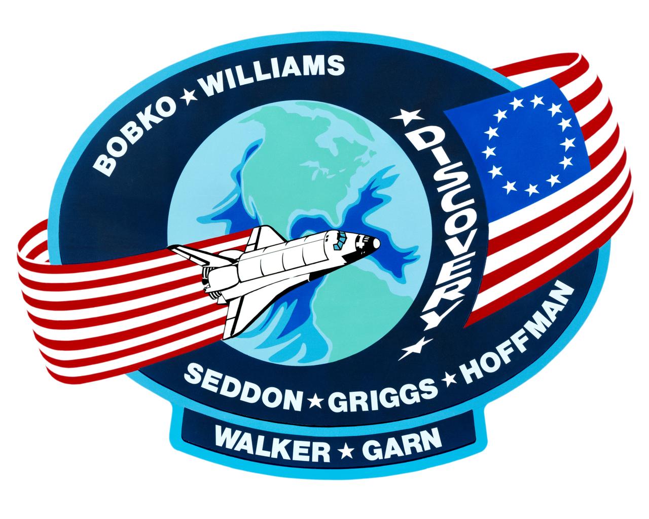
S85-28989 (March 1985) --- The dominant features of the STS-51D emblem are an orbit formed by a Colonial American flag and a space shuttle. The flag in orbit signifies the U.S. flag to indicate that it comes from this country and the American people. The original 13-star flag is used to symbolize a continuity of technical achievement and progress since colonial times. The name Discovery preceding the flag represents the spirit of Discovery and exploration of new frontiers which have been a hallmark of American people even before they were formed together as a nation. The crew members are Karol J. Bobko, Donald E. Williams, Rhea Seddon, S. David Griggs and Jeffrey A. Hoffman of NASA; and Charles D. Walker, representing McDonnell Douglas Corporation; and U. S. Senator Jake Garn. The NASA insignia design for space shuttle flights is reserved for use by the astronauts and for other official use as the NASA Administrator may authorize. Public availability has been approved only in the forms of illustrations by the various news media. When and if there is any change in this policy, which is not anticipated, the change will be publicly announced. Photo credit: NASA
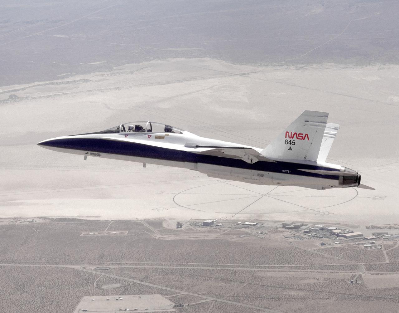
The National Aeronautics and Space Administration's Systems Research Aircraft (SRA), a highly modified F-18 jet fighter, on an early research flight over Rogers Dry Lake. The former Navy aircraft was flown by NASA's Dryden Flight Research Center at Edwards Air Force Base, California, to evaluate a number of experimental aerospace technologies in a multi-year, joint NASA/DOD/industry program. Among the more than 20 experiments flight-tested were several involving fiber optic sensor systems. Experiments developed by McDonnell-Douglas and Lockheed-Martin centered on installation and maintenace techniques for various types of fiber-optic hardware proposed for use in military and commercial aircraft, while a Parker-Hannifin experiment focused on alternative fiber-optic designs for postion measurement sensors as well as operational experience in handling optical sensor systems. Other experiments flown on this testbed aircraft included electronically-controlled control surface actuators, flush air data collection systems, "smart" skin antennae and laser-based systems. Incorporation of one or more of these technologies in future aircraft and spacecraft could result in signifigant savings in weight, maintenance and overall cost.
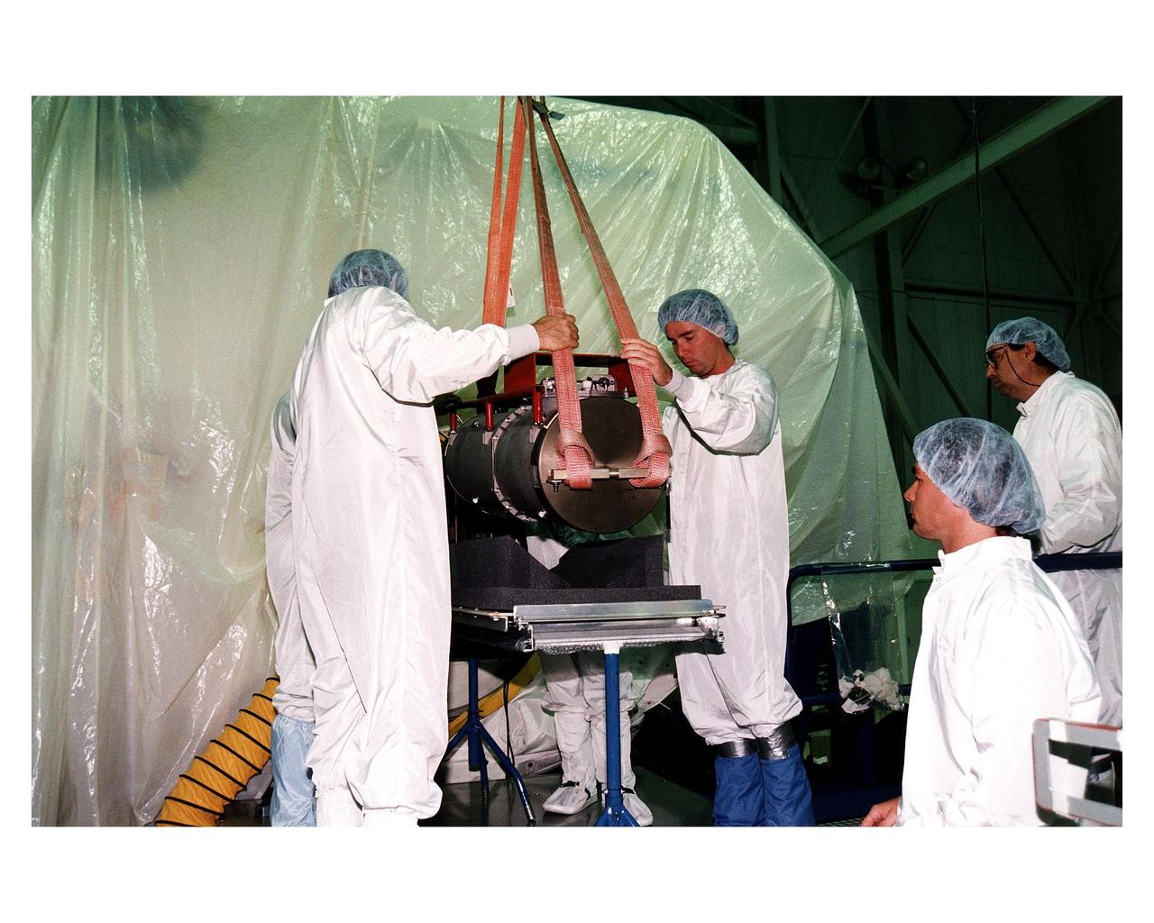
KENNEDY SPACE CENTER, FLA. -- McDonnell Douglas-SPACEHAB technicians oversee the move of a Russian-made oxygen generator to a SPACEHAB Double Module, at rear, in the SPACEHAB Payload Processing Facility. With faces visible in center foreground, from left, are Mark Halavin and Marc Tuttle; Mike Vawter is at far right. The oxygen generator, manufactured in Russia by RSC Energia, will be carried aboard the Space Shuttle Atlantis on Mission STS-84 for the Shuttle’s scheduled docking with the Russian Space Station Mir next month. The nearly 300-pound generator will replace one of two Mir units that have been malfunctioning recently. The generator functions by electrolysis, which separates water into its oxygen and hydrogen components. The hydrogen is vented and the oxygen is used for breathing by the Mir crew. The generator is 4.2 feet in length and 1.4 feet in diameter. STS-84, which is planned to include a Mir crew exchange of astronaut C. Michael Foale for Jerry M. Linenger, is targeted for a May 15 liftoff. It will be the sixth Shuttle-Mir docking
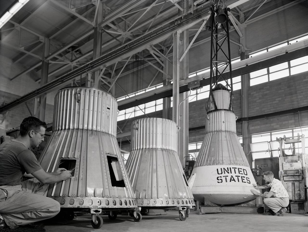
Assembling the Little Joe capsules. The capsules were manufactured in-house by Langley technicians. Three capsules are shown here in various stages of assembly. The escape tower and rocket motors shown on the completed capsule would be removed before shipping and finally assembly for launching at Wallops Island. Joseph Shortal wrote (vol. 3, p. 32): Design of the Little Joe capsules began at Langley before McDonnell started on the design of the Mercury capsule and was, therefore, a separate design. Although it was not designed to carry a man, it did have to carry a monkey. It had to meet the weight and center of gravity requirements of Mercury and withstand the same aerodynamic loads during the exit trajectory. Although in comparison with the overall Mercury Project, Little Joe was a simple undertaking, the fact that an attempt was made to condense a normal two-year project into a 6-month one with in house labor turned it into a major undertaking for Langley. Project Mercury: Little Joe: Boilerplate Mercury spacecraft undergo fabrication at the shops of the Langley Research Center. They will launched atop Little Joe rockets to test the spacecraft recovery systems. -- Published in Joseph A. Shortal, History of Wallops Station: Origins and Activities Through 1949, (Wallops Island, VA: National Aeronautics and Space Administration, Wallops Station, nd), Comment Edition. L59-4947 Technicians prepare a Little Joe launch vehicle prototype for the Mercury space program, 1959. Photograph published in Winds of Change, 75th Anniversary NASA publication, page 76, by James Schultz
The Fan Noise Test Facility built at the Lewis Research Center to obtain far-field noise data for the National Aeronautics and Space Administration (NASA) and General Electric Quiet Engine Program. The engine incorporated existing noise reduction methods into an engine of similar power to those that propelled the Boeing 707 or McDonnell-Douglas DC-8 airliner. The new the low-bypass ratio turbofan engines of the 1960s were inherently quieter than their turbojet counterparts, researchers had a better grasp of the noise generation problem, and new acoustic technologies had emerged. Lewis contracted General Electric in 1969 to build and aerodynamically test three experimental engines with 72-inch diameter fans. The engines were then brought to Lewis and tested with an acoustically treated nacelle. This Fan Noise Test Facility was built off of the 10- by 10-Foot Supersonic Wind Tunnel’s Main Compressor and Drive Building. Lewis researchers were able to isolate the fan’s noise during these initial tests by removing the core of the engine. The Lewis test rig drove engines to takeoff tip speeds of 1160 feet per second. The facility was later used to test a series of full-scale model fans and fan noise suppressors to be used with the quiet engine. NASA researchers predicted low-speed single-stage fans without inlet guide vanes and with large spacing between rotors and stators would be quieter. General Electric modified a TF39 turbofan engine by removing the the outer protion of the fan and spacing the blade rows of the inner portion. The tests revealed that the untreated version of the engine generated less noise than was anticipated, and the acoustically treated nacelle substantially reduced engine noise.

Assembling the Little Joe capsules. The capsules were manufactured in-house by Langley technicians. Three capsules are shown here in various stages of assembly. The escape tower and rocket motors shown on the completed capsule would be removed before shipping and finally assembly for launching at Wallops Island. Joseph Shortal wrote (vol. 3, p. 32): Design of the Little Joe capsules began at Langley before McDonnell started on the design of the Mercury capsule and was, therefore, a separate design. Although it was not designed to carry a man, it did have to carry a monkey. It had to meet the weight and center of gravity requirements of Mercury and withstand the same aerodynamic loads during the exit trajectory. Although in comparison with the overall Mercury Project, Little Joe was a simple undertaking, the fact that an attempt was made to condense a normal two-year project into a 6-month one with in house labor turned it into a major undertaking for Langley. Project Mercury: Little Joe: Boilerplate Mercury spacecraft undergo fabrication at the shops of the Langley Research Center. They will launched atop Little Joe rockets to test the spacecraft recovery systems. -- Published in Joseph A. Shortal, History of Wallops Station: Origins and Activities Through 1949, (Wallops Island, VA: National Aeronautics and Space Administration, Wallops Station, nd), Comment Edition. L59-4947 Technicians prepare a Little Joe launch vehicle prototype for the Mercury space program, 1959. Photograph published in Winds of Change, 75th Anniversary NASA publication, page 76, by James Schultz
Assembling the Little Joe capsules. The capsules were manufactured in-house by Langley technicians. Three capsules are shown here in various stages of assembly. The escape tower and rocket motors shown on the completed capsule would be removed before shipping and finally assembly for launching at Wallops Island. Joseph Shortal wrote (vol. 3, p. 32): Design of the Little Joe capsules began at Langley before McDonnell started on the design of the Mercury capsule and was, therefore, a separate design. Although it was not designed to carry a man, it did have to carry a monkey. It had to meet the weight and center of gravity requirements of Mercury and withstand the same aerodynamic loads during the exit trajectory. Although in comparison with the overall Mercury Project, Little Joe was a simple undertaking, the fact that an attempt was made to condense a normal two-year project into a 6-month one with in house labor turned it into a major undertaking for Langley. Project Mercury: Little Joe: Boilerplate Mercury spacecraft undergo fabrication at the shops of the Langley Research Center. They will launched atop Little Joe rockets to test the spacecraft recovery systems. -- Published in Joseph A. Shortal, History of Wallops Station: Origins and Activities Through 1949, (Wallops Island, VA: National Aeronautics and Space Administration, Wallops Station, nd), Comment Edition. L59-4947 Technicians prepare a Little Joe launch vehicle prototype for the Mercury space program, 1959. Photograph published in Winds of Change, 75th Anniversary NASA publication, page 76, by James Schultz
The Westinghouse 19XB turbojet seen from the side in the Altitude Wind Tunnel (AWT) test section at the National Advisory Committee for Aeronautics (NACA) Aircraft Engine Research Laboratory. Westinghouse started the development of a series of relatively small axial-flow turbojets for the Navy shortly after Pearl Harbor. In 1943 the 19A engine became both the first operational US-designed jet engine and the only U.S. turbojet incorporated into an aircraft during the war in Europe. In March 1943 Westinghouse agreed to create an improved six-stage 1400-pound thrust version, the 19B. The engine underwent its first test run a year later in March 1944. Almost immediately the navy agreed to Westinghouse’s proposal for the even larger 10-stage, 1600-pound-thrust 19XB prototype. By July 1944 the navy had contracted with the NACA for the testing of both engines in the AWT. The tunnel was the nation’s only facility for studying full-scale engines in simulated altitude conditions. The wind tunnel investigations, which began on September 9, 1944, revealed the superiority of the previously untested 19XB over the 19B. The 19B engines failed to restart consistently and suffered combustion blowouts above 17,000 feet. The 19XB, however, performed well and restarted routinely at twice that altitude. Two months later on January 26, 1945, two 19Bs powered a McDonnell XFD–1 Phantom, the US Navy’s first fighter jet, on its initial flight. Following its exceptional performance in the AWT, the 19XB engines soon replaced the 19Bs in the Phantom.
Astronaut John Young (above) was one of 14 astronauts, 8 NASA test pilots, and 2 McDonnell test pilots who took part in simulator studies. Young piloted the simulator on November 12, 1963 Arthur Vogeley wrote: "Many of the astronauts have flown this simulator in support of the Gemini studies and they, without exception, appreciated the realism of the visual scene. The simulator has also been used in the development of pilot techniques to handle certain jet malfunctions in order that aborts could be avoided. In these situations large attitude changes are sometimes necessary and the false motion cues that were generated due to earth gravity were somewhat objectionable; however, the pilots were readily able to overlook these false motion cues in favor of the visual realism." Roy F. Brissenden wrote: "The basic Gemini control studies developed the necessary techniques and demonstrated the ability of human pilots to perform final space docking with the specified Gemini-Agena systems using only visual references. ... Results... showed that trained astronauts can effect the docking with direct acceleration control and even with jet malfunctions as long as good visual conditions exist.... Probably more important than data results was the early confidence that the astronauts themselves gained in their ability to perform the maneuver in the ultimate flight mission." -- Published in Barton C. Hacker and James M. Grimwood, On the Shoulders of Titans: A History of Project Gemini, NASA SP-4203; A.W. Vogeley, "Discussion of Existing and Planned Simulators For Space Research," Paper presented at the Conference on the Role of Simulation in Space Technology, August 17-21, 1964; Roy F. Brissenden, "Initial Operations with Langley's Rendezvous Docking Facility," Langley Working Paper, LWP-21, 1964.

Assembling the Little Joe capsules. The capsules were manufactured in-house by Langley technicians. Three capsules are shown here in various stages of assembly. The escape tower and rocket motors shown on the completed capsule would be removed before shipping and finally assembly for launching at Wallops Island. Joseph Shortal wrote (vol. 3, p. 32): Design of the Little Joe capsules began at Langley before McDonnell started on the design of the Mercury capsule and was, therefore, a separate design. Although it was not designed to carry a man, it did have to carry a monkey. It had to meet the weight and center of gravity requirements of Mercury and withstand the same aerodynamic loads during the exit trajectory. Although in comparison with the overall Mercury Project, Little Joe was a simple undertaking, the fact that an attempt was made to condense a normal two-year project into a 6-month one with in house labor turned it into a major undertaking for Langley. Project Mercury: Little Joe: Boilerplate Mercury spacecraft undergo fabrication at the shops of the Langley Research Center. They will launched atop Little Joe rockets to test the spacecraft recovery systems. -- Published in Joseph A. Shortal, History of Wallops Station: Origins and Activities Through 1949, (Wallops Island, VA: National Aeronautics and Space Administration, Wallops Station, nd), Comment Edition. L59-4947 Technicians prepare a Little Joe launch vehicle prototype for the Mercury space program, 1959. Photograph published in Winds of Change, 75th Anniversary NASA publication, page 76, by James Schultz