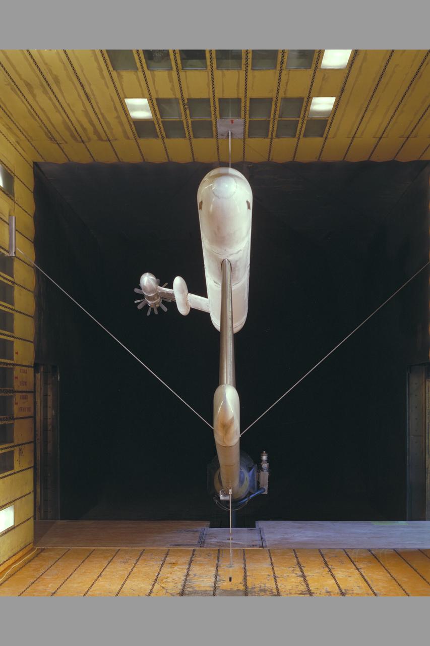
McDonnell Douglas Hub (Ultra-High Bypass) Model and SAAB Wake Rake Test 14ft W.T. Test-060-1-14, Turbo Fan Configuration
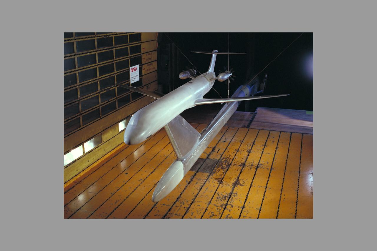
McDonnell Douglas Hub (Ultra-High Bypass) Model and SAAB Wake Rake Test 14ft W.T. Test-060-1-14, Turbo Fan Configuration
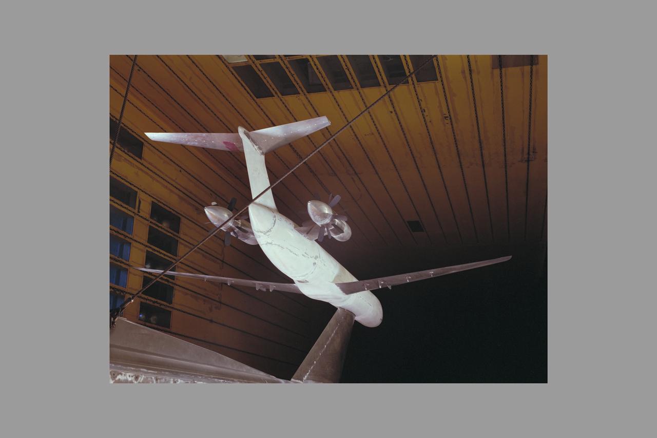
McDonnell Douglas Hub (Ultra-High Bypass) Model and SAAB Wake Rake Test 14ft W.T. Test-060-1-14, Turbo Fan Configuration
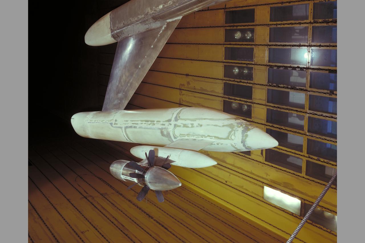
McDonnell Douglas Hub (Ultra-High Bypass) Model and SAAB Wake Rake Test 14ft W.T. Test-060-1-14, Turbo Fan Configuration
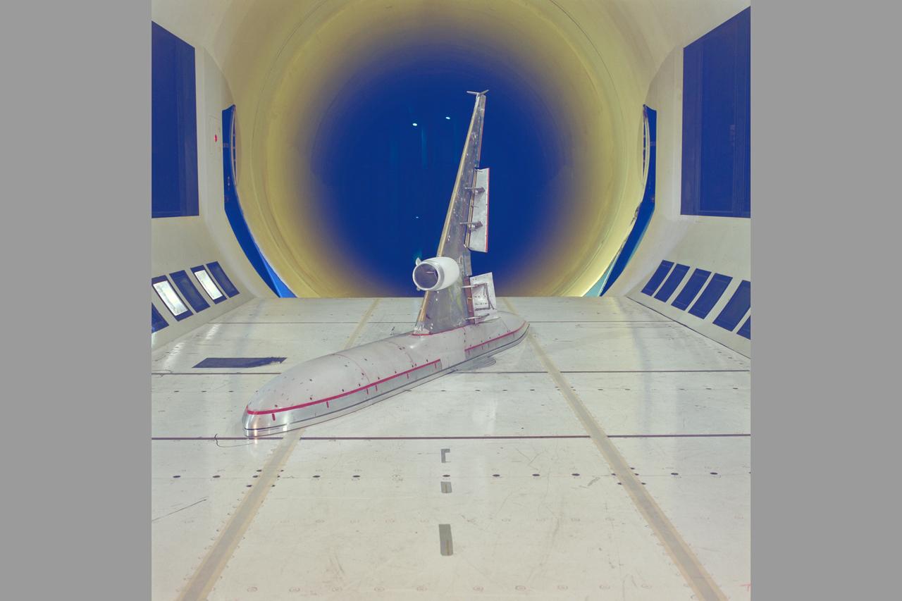
McDonnell-Douglas MD-11 Semi-span model test-12-0016 in 12ft WT
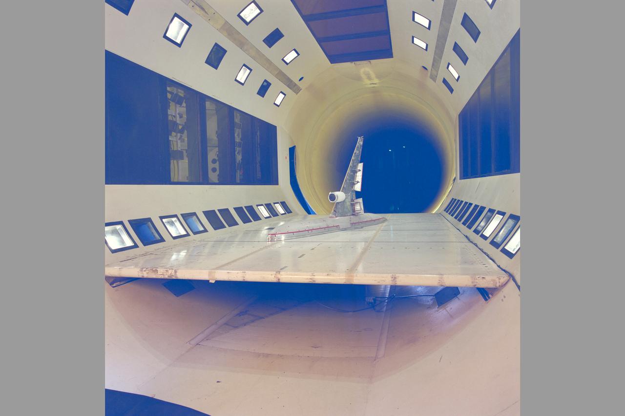
McDonnell-Douglas MD-11 Semi-span model test-12-0016 in 12ft WT
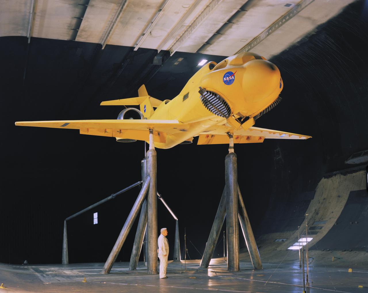
3/4 front view of McDonnell-Douglas Large-Scale lift fan, vertical and/or short take-off and landing (V/STOL), transport model. Francis Malerick in photograph. The McDonnell Douglas DC-9 (initially known as the Douglas DC-9) is a twin-engine, single-aisle jet airliner.
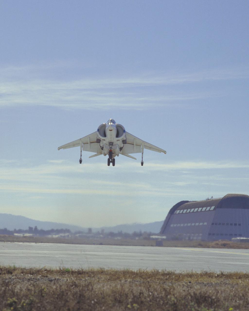
McDonnell Douglas YAV-8B (Bu. No. 158394 NASA 704 VSRA) Harrier V/STOL Systems Research Aircraft hover Note: Used in publication in Flight Research at Ames; 57 Years of Development and Validation of Aeronautical Technology NASA SP-1998-3300 fig.125
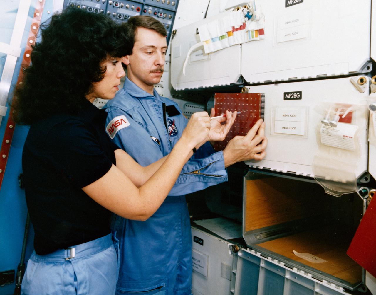
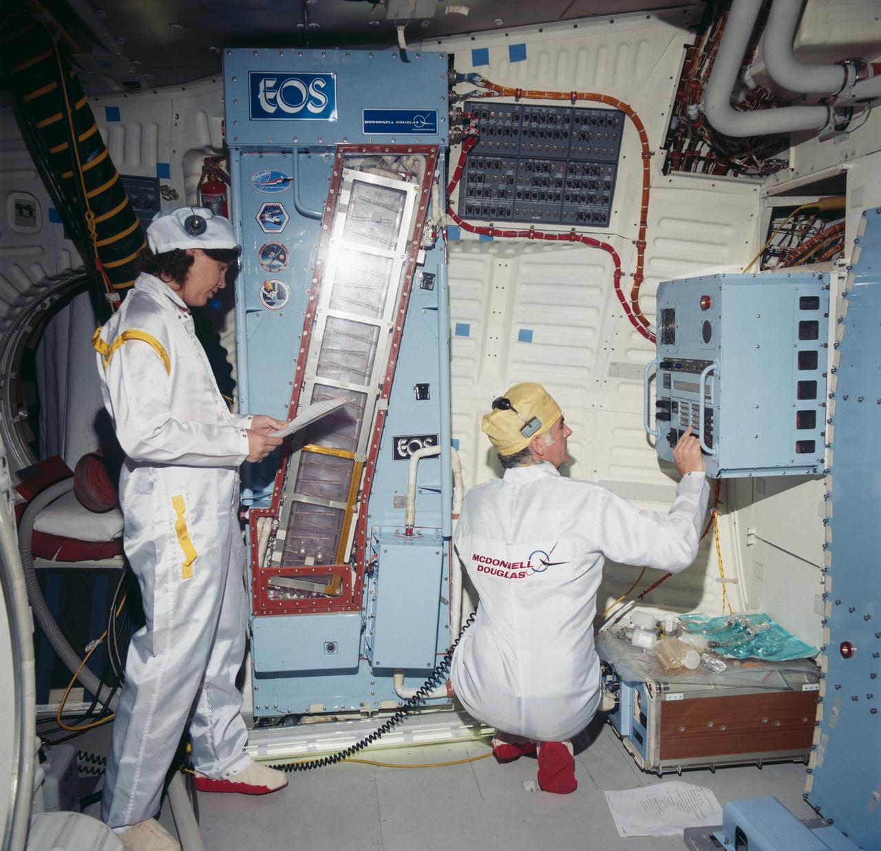
S84-35757 (May 1984) --- Astronaut Judith A. Resnik, 41-D mission specialist, and Charles Walker, payload specialist for that June 1984 flight, prepare for some scheduled intravehicular activity involving the continuous flow electrophoresis systems (CFES) experiment. CFES will join the six-member crew aboard the Earth-orbiting Discovery for a seven day mission. The two share in preparing a sample to be processed by the CFES. In the background are stowage lockers and a CFES trainer-- part of the Shuttle one-g trainer at NASA's Johnson Space Center (JSC). Walker, an engineer at McDonnell Douglas Astronautics Co. in St. Louis, Missouri, will be the first Shuttle payload specialist to represent a project designed for commercial purposes. As payload specialist, his job will be to run the materials electrophoresis-operations-in-space project. The project is aimed at separating large quantities of biological materials in space for ultimate use in new pharmaceuticals. The photo was taken by a McDonnell Douglas photographer.
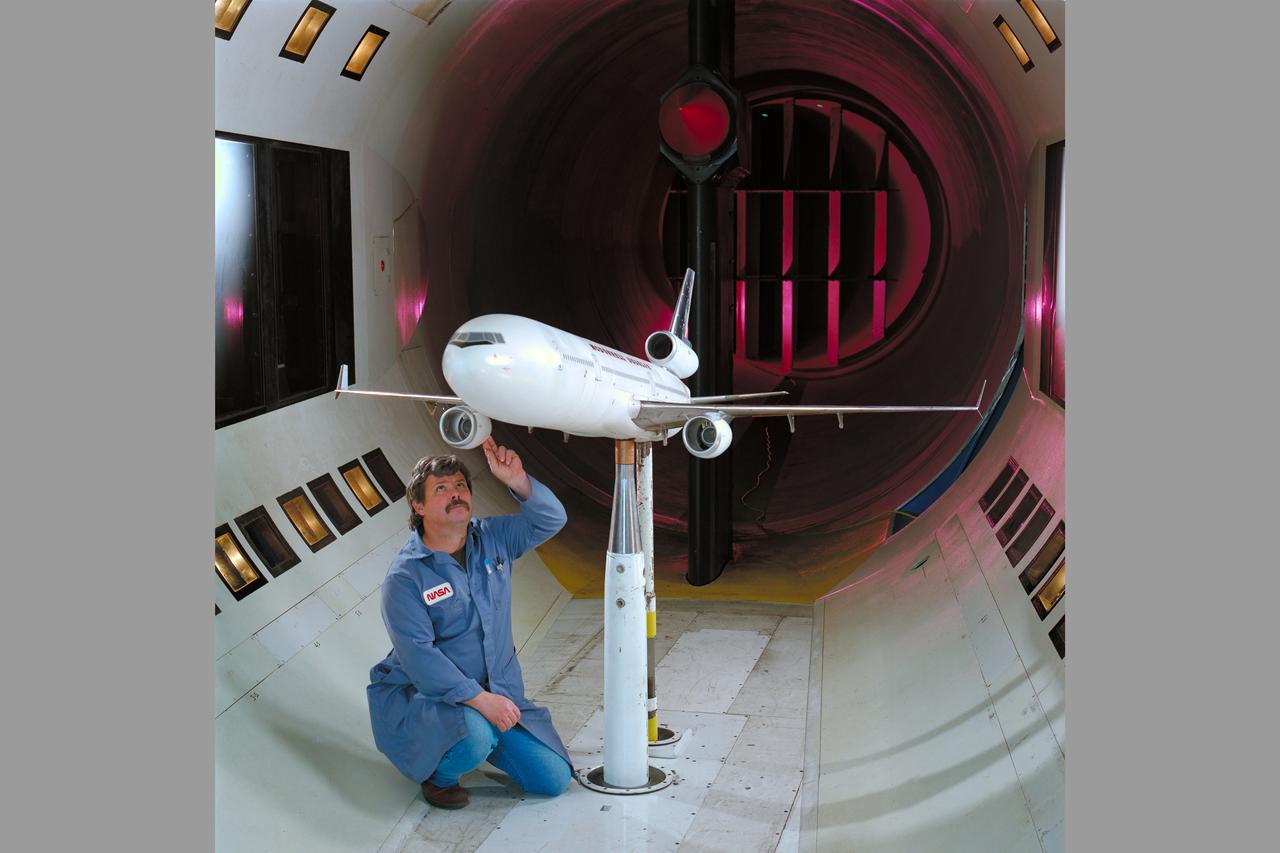
Mc Donnell Douglas MD-11 Model in Ames 12ft. W.T. (1st Non-NASA customer of the refurbished W.T.)
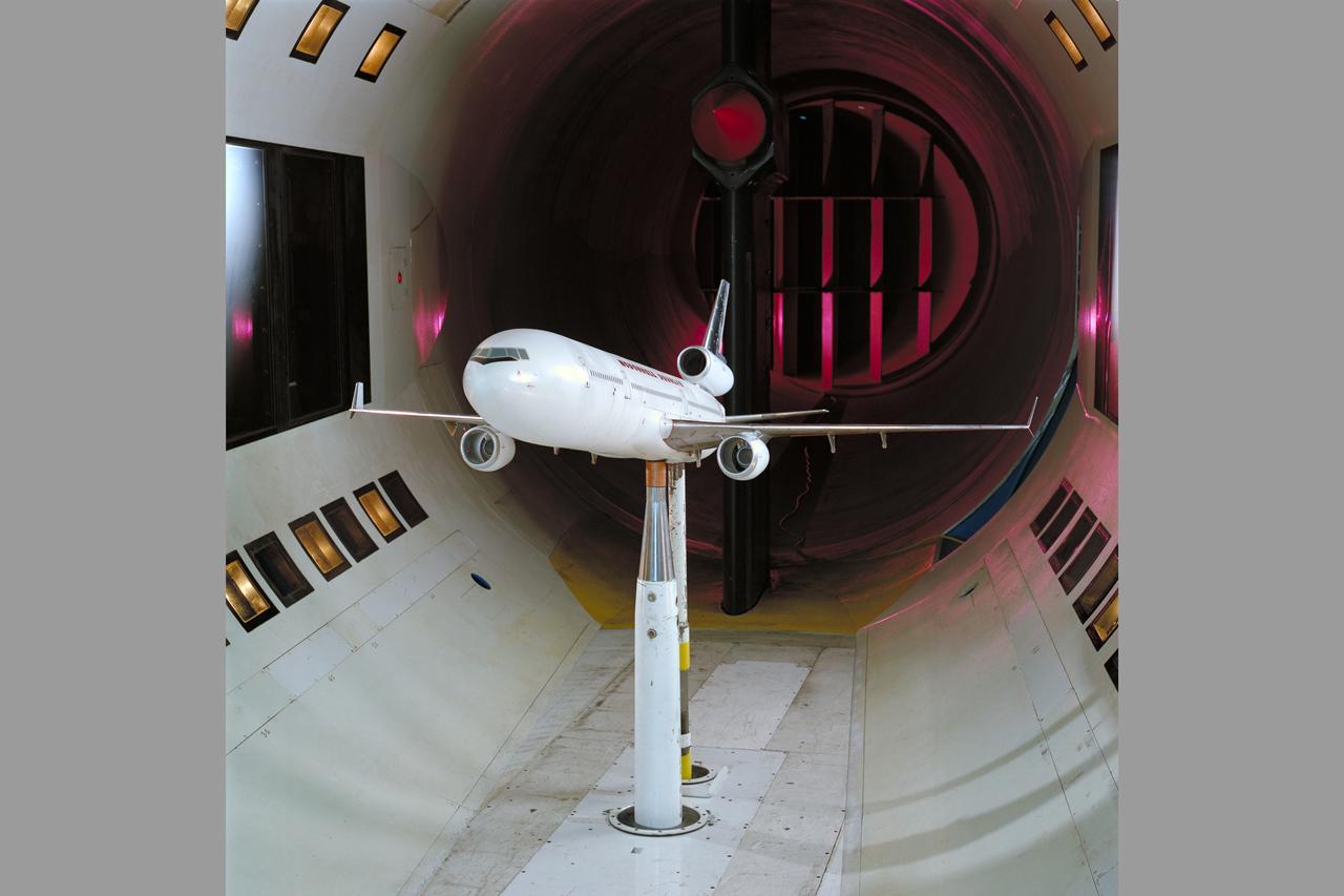
Mc Donnell Douglas MD-11 Model in Ames 12ft. W.T. (1st Non-NASA customer of the refurbished W.T.)

Mc Donnell Douglas MD-11 Model in Ames 12ft. W.T. (1st Non-NASA customer of the refurbished W.T.)
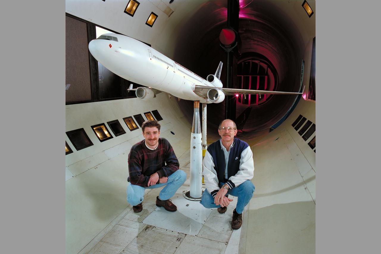
Mc Donnell Douglas MD-11 Model in Ames 12ft. W.T. with members of the MC Donnell Douglas crew (1st Non-NASA customer of the refurbished W.T.)
Mc Donnell Douglas MD-11 Model in Ames 12ft. W.T. (1st Non-NASA customer of the refurbished W.T.)

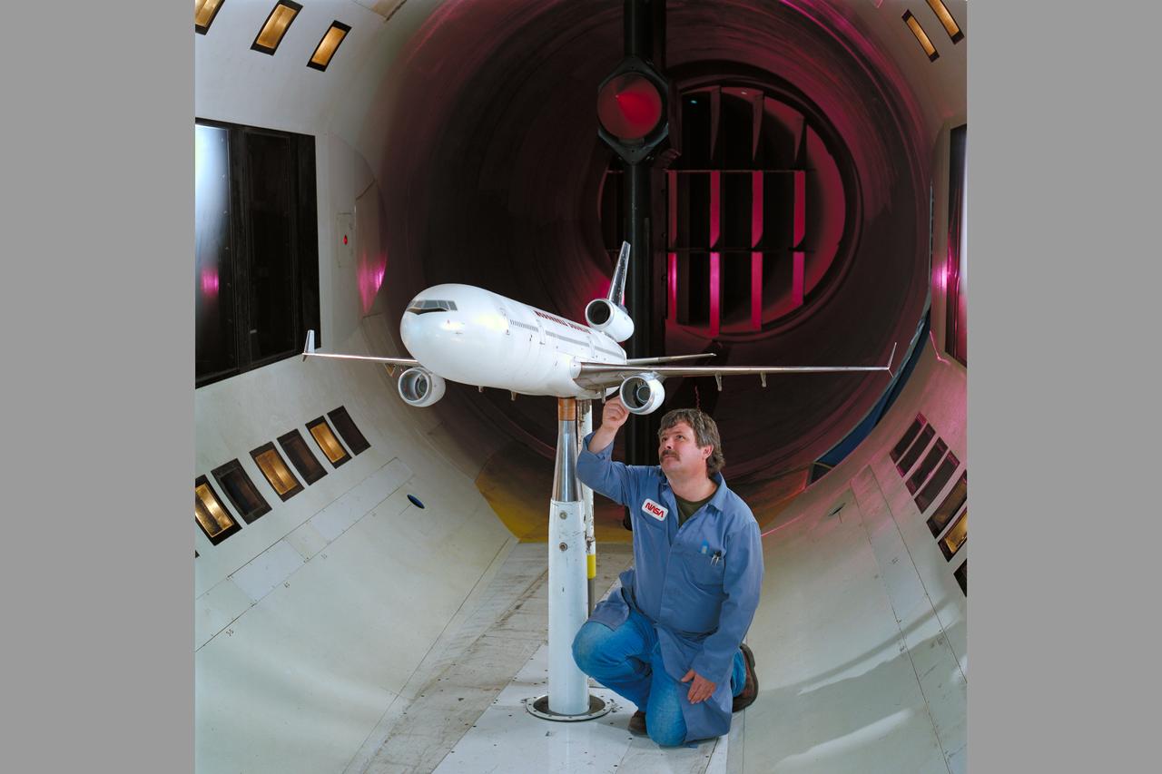
Mc Donnell Douglas MD-11 Model in Ames 12ft. W.T. with Ron Strong (1st Non-NASA customer of the refurbished W.T.)
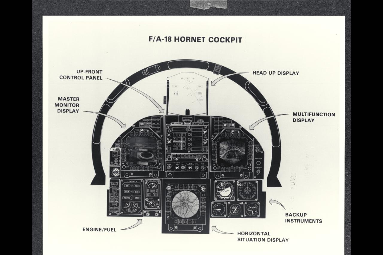
McDonnell Douglas F/A-18A Hornet cockpit drawing
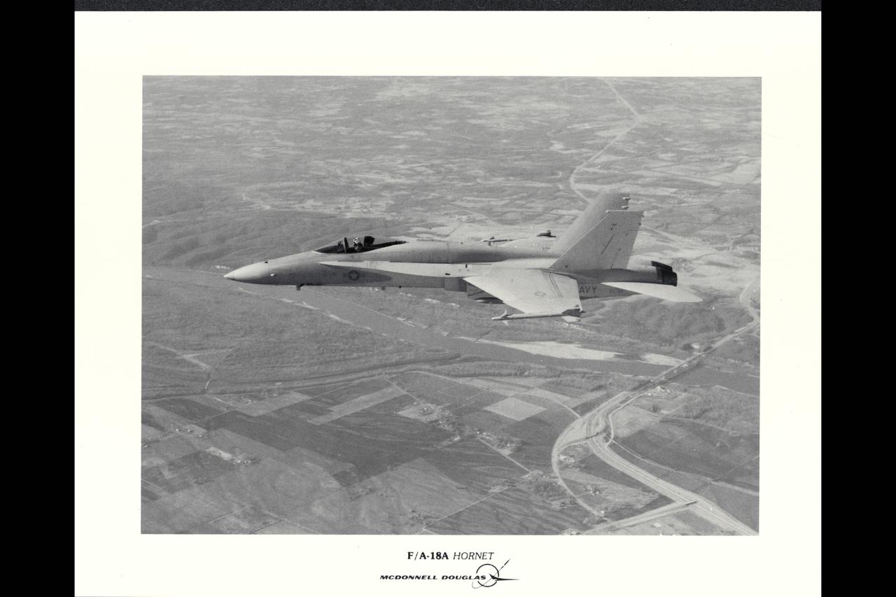
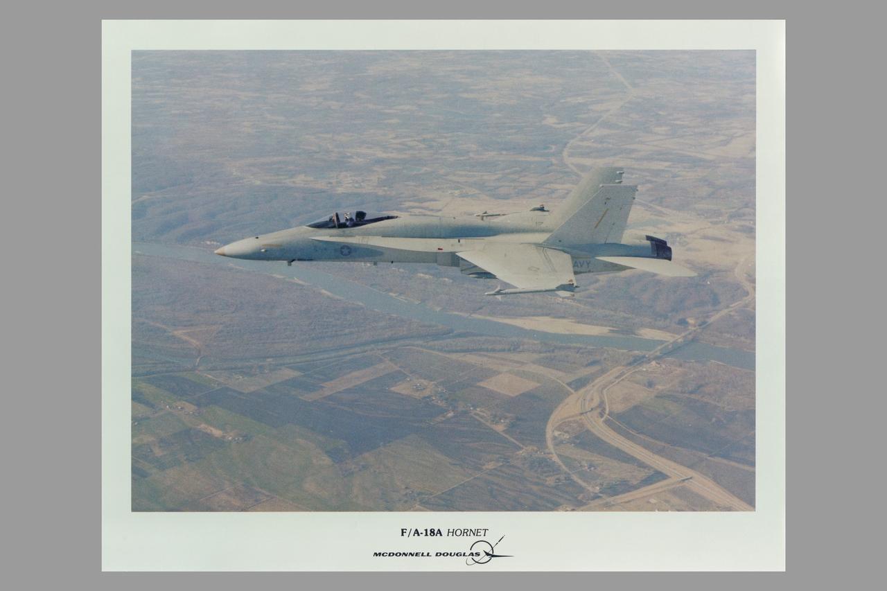
McDonnell Douglas F/A-18A Hornet in flight
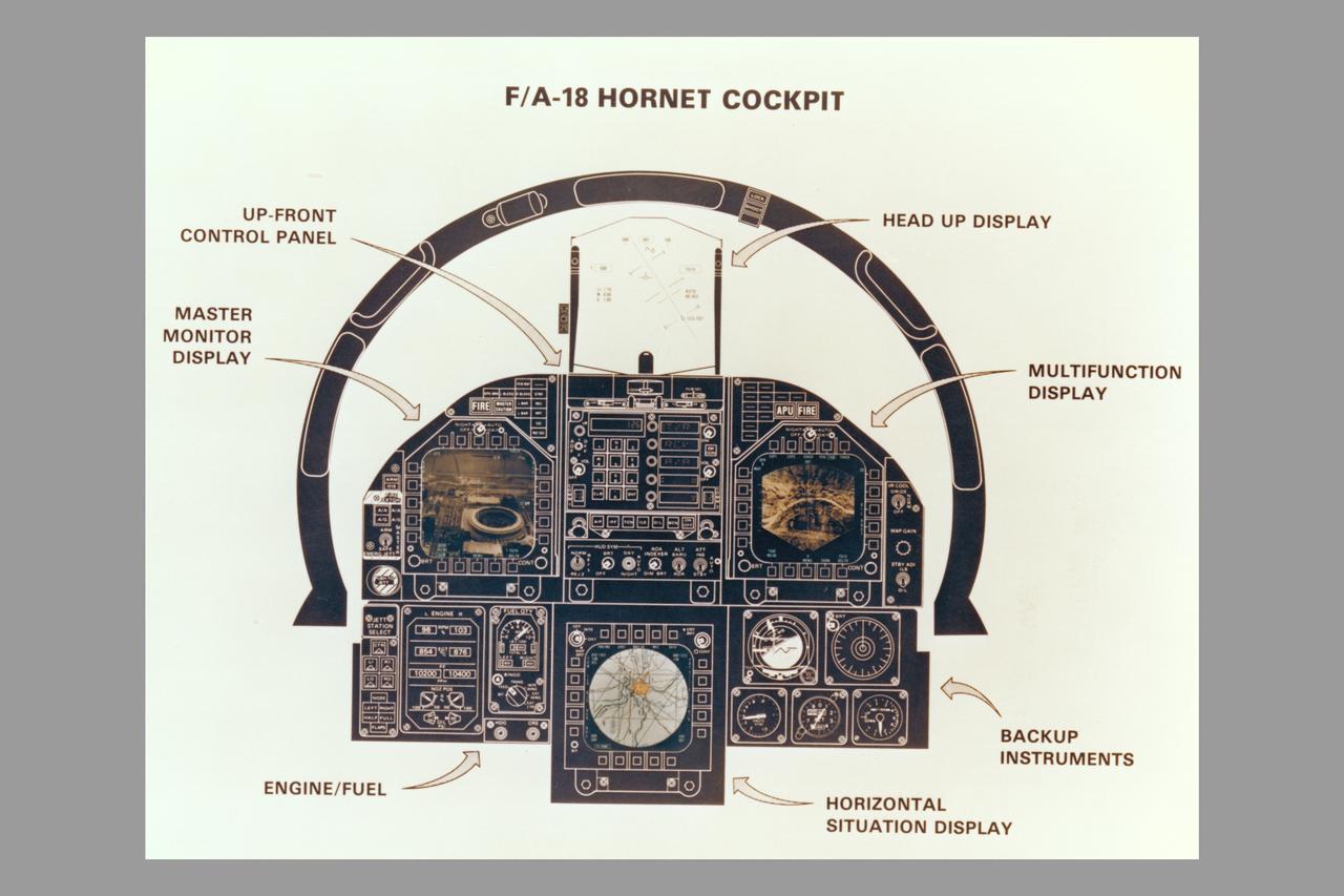
McDonnell Douglas F/A-18A Hornet cockpit drawing
McDonnell Douglas F/A-18A Hornet in flight
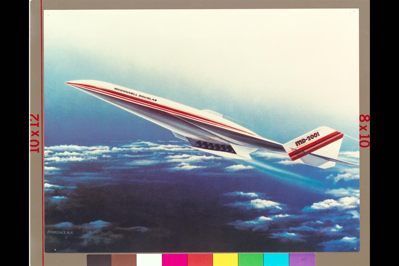
Art from McDonnell Douglas National Aerospace Plane (NASP) Md Donnell Douglas MD-2001 (artist: Horonzak)
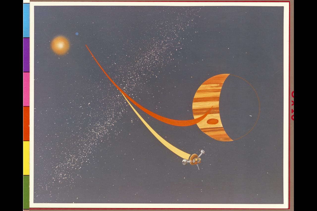
Pioneer Galileo mission trajectory artwork (ref: McDonnell Douglas May, 77 # D4C-117575-4)
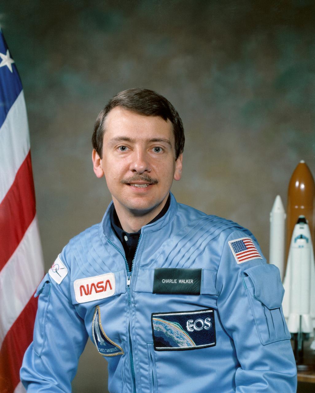
S84-27269 (16 Feb 1984) --- Astronaut Charles (Charlie) D. Walker, payload specialist and McDonnell-Douglas Civilian Engineer.
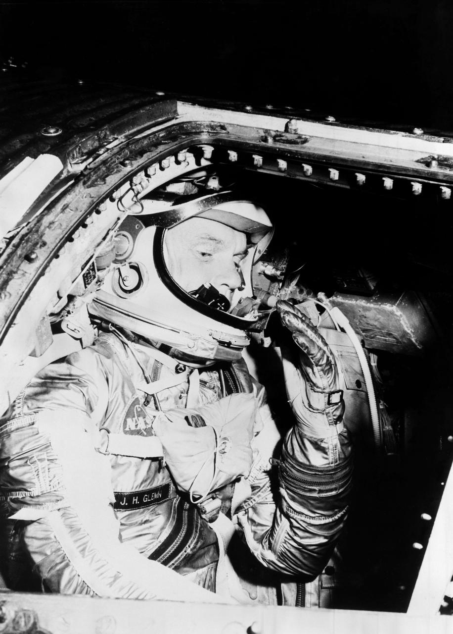
S62-01021 (1962) --- Astronaut John H. Glenn Jr. during training procedures in a trainer at the McDonnell Douglas training facility in St. Louis, Missouri. Photo credit: NASA
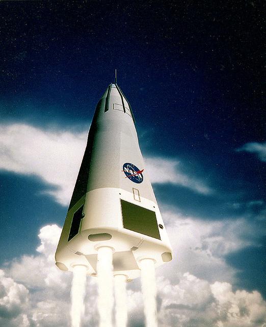
This is the McDornell Douglas CD-XA Reusable Launch Vehicle (RLV) concept. The Delta Clipper-Experimental (DC-X) was originally developed by McDonnell Douglas for the DOD. The DC-XA is a single-stage-to-orbit, vertical takeoff/vertical landing, launch vehicle concept, whose development is geared to significantly reduce launch cost and provided a test bed for NASA Reusable Launch Vehicle (RLV) technology as the Delta Clipper-Experimental Advanced (DC-XA). The program was discontinued in 2003.
KSC-84PC-248 (For release Aug. 27, 1984) --- The Continuous Flow Electrophoresis System (CFES) is being installed in the middeck of the Orbiter Discovery in preparation for the flight of mission STS-41D in June. The CFES, originating from the McDonnell Douglas Astronautics Co. includes a fluid systems module, and experiment control and monitoring module, a sample storage module and a pump/accumulator package along with miscellaneous equipment stored in a middeck locker. Photo credit: NASA

A Delta II rocket carrying the Geomagnetic Tail Lab (GEOTAIL) spacecraft lifts off at Launch Complex 17, Kennedy Space Center (KSC) into a cloud-dappled sky. This liftoff marks the first Delta launch under the medium expendable launch vehicle services contract between NASA and McDonnell Douglas Space Systems Co. The GEOTAIL mission, a joint US/Japanese project, is the first in a series of five satellites to study the interactions between the Sun, the Earth's magnetic field, and the Van Allen radiation belts.
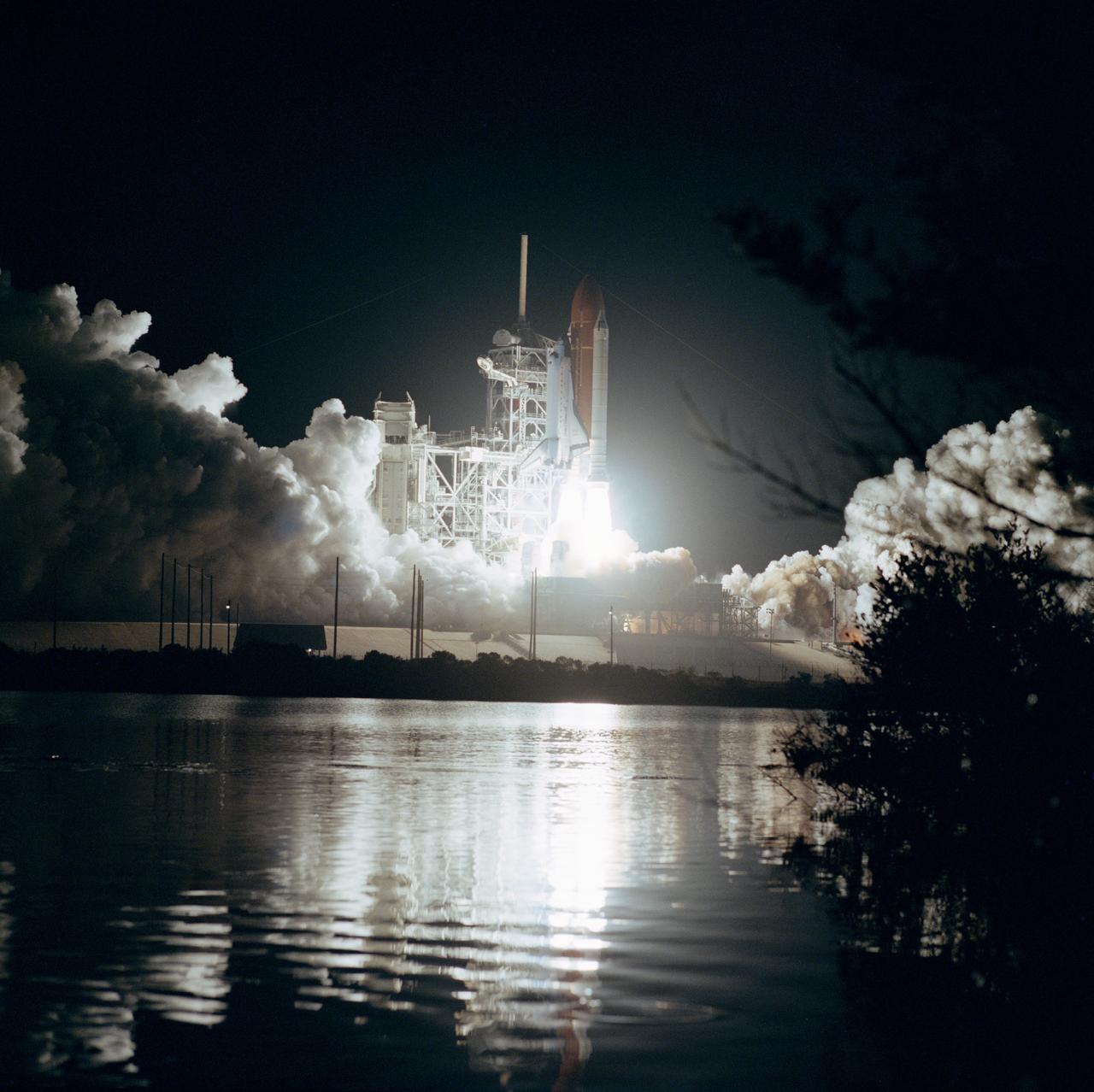
61B-S-067 (26 Nov 1985) --- Space Shuttle Atlantis ascends into the night sky at 7:29 p.m. (EST), November 26, with a seven member crew and three communications satellites aboard. The STS 61-B crewmembers are Brewster Shaw Jr., Bryan D. O?Connor, Mary L. Cleave, Sherwood C. Spring, Jerry L. Ross and Payload Specialists Rodolfo Neri of Mexico (Morelos) and Charles D. Walker of McDonnell Douglas.
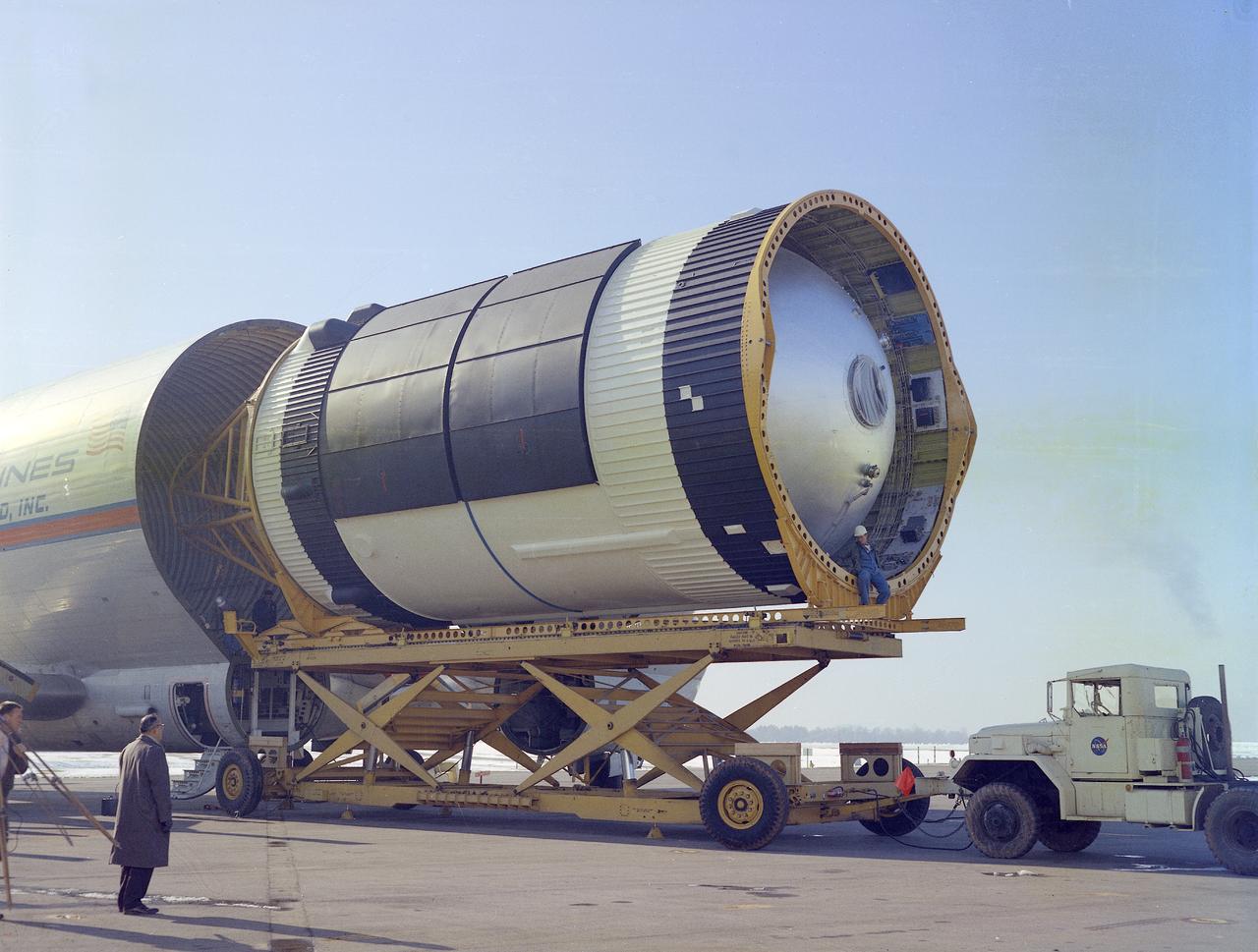
This photograph was taken at the Redstone airfield, Huntsville, Alabama, during the unloading of the Saturn V S-IVB stage that housed the Orbital Workshop (OWS) from the Super Guppy, the NASA plane that was specially built to carry oversized cargo. The OWS measured 22 feet (6.7 m) in diameter, and 48 feet (14.6 m) in length. The Saturn V S-IVB stage was modified at the McDornell Douglas facility at Huntington Beach, California, for a new role, which was to house the OWS. In addition to the test articles, engineering mockups, and flight equipment, both McDonnell Douglas and Martin Marietta built 0-G trainers, neutral buoyancy trainers, and high-fidelity mockups for the 1-G trainer to be used in the KC-135 aircraft. The Marshall Space Flight Center had program management responsibility for the development of Skylab hardware and experiments.

Roy D. Bridges Jr., KSC's next center director, at right, poses in the firing room of the Launch Control Center with two top contractor officials at Kennedy Space Center during the STS-82 launch of Discovery on the second Hubble Space Telescope servicing mission. From left, are Michael J. McCulley, vice president and associate program manager for ground operations for United Space Alliance at KSC; and Bruce Melnick, vice president of McDonnell Douglas Space and Defense Systems-KSC. Bridges is slated to become KSC's seventh center director on March 2, succeeding Jay F. Honeycutt
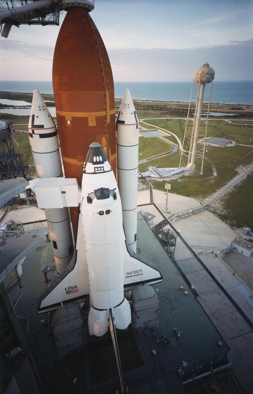
KSC-84PC-476 (For release Aug. 29, 1984) --- Orbiter Discovery is poised on Launch Pad 39A as the sun sets the evening prior to its maiden launch. Space shuttle Discovery (STS-41D) was successfully launched at 8:41 a.m. Aug. 30, 1984, after two failed attempts in June. Carrying a crew of six astronauts and three satellites, Discovery is the third in NASA?s stable of four Space Transportation System orbiters. The six-person crew includes Commander Henry Hartsfield, Pilot Michael Coats, Mission Specialists Judith Resnik, Mike Mullane and Steve Hawley and the first commercial payload specialist, Charles Walker of McDonnell Douglas. Photo credit: NASA
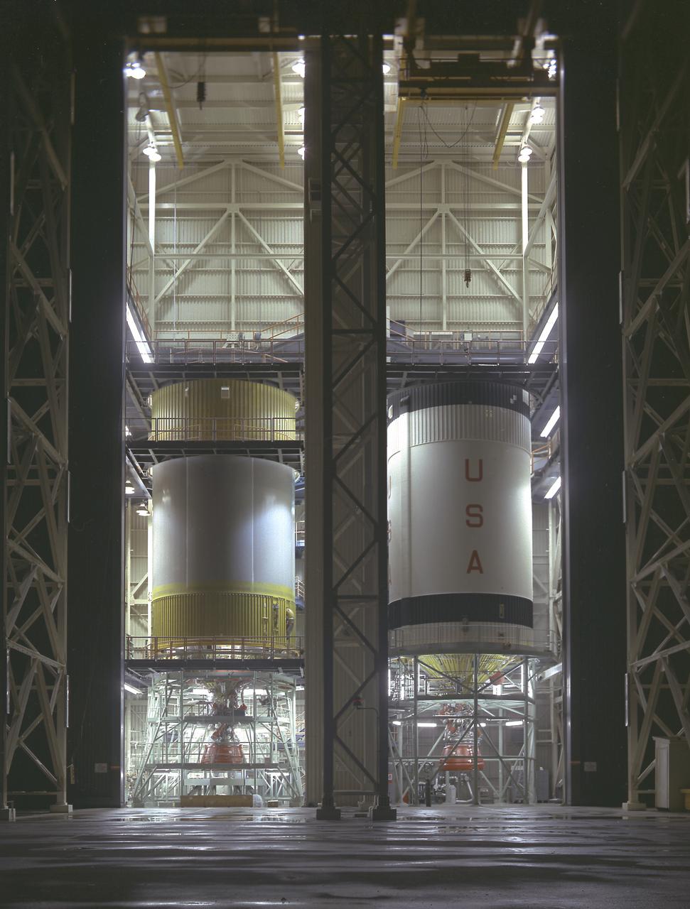
S-IVB-505 and S-IVB-211, the flight version of the S-IVB stages, in the McDornell Douglas' S-IVB Assembly and Checkout Tower in Huntington Beach, California. As a part of the Marshall Space Flight Center `s "building block" approach to the Saturn vehicle development, the S-IVB stage, in its 200 series, was utilized as the Saturn IB launch vehicle's second stage, and, in its 500 series, the Saturn V's third stage. The S-IVB was powered by a single J-2 engine, initially capable of 200,000 pounds of thrust.

S85-28647 (28 Feb 1985) --- The seven members of the STS-51D mission are pictured in the midst of a busy training schedule in preparation for NASA's 16th Space Shuttle flight, currently planned for April of this year. The crewmembers are (front row, left to right), Karol J. Bobko, commander; Donald E. Williams, pilot; Rhea Seddon and Jeffrey A. Hoffman, mission specialists; and (back row) S. David Griggs, mission specialist; and Charles D. Walker and United States Senator Jake Garn (Republican - Utah) both payload specialists. Walker represents McDonnell-Douglas Corporation. EDITOR'S NOTE: Mission specialist S. David Griggs died June 17, 1989, near Earle, Arkansas, in the crash of a World-War-II-era training plane.
KENNEDY SPACE CENTER, FLA. -- McDonnell Douglas-SPACEHAB technicians prepare to place a Russian-made oxygen generator into position for transport in a SPACEHAB Double Module being processed for flight on Space Shuttle Mission STS-84. The module is undergoing preflight preparations in the SPACEHAB Payload Processing Facility just outside of Gate 1 on Cape Canaveral Air Station. The Space Shuttle Atlantis will carry the oxygen generator to the Russian Space Station Mir to replace one of two Mir units that have been malfunctioning recently. The nearly 300-pound generator functions by electrolysis, which separates water into its oxygen and hydrogen components. The hydrogen is vented and the oxygen is used for breathing by the Mir crew. The generator is 4.2 feet long with a diameter of 1.4 feet. STS-84, which is planned to include a Mir crew exchange of astronaut C. Michael Foale for Jerry M. Linenger, is targeted for a May 15 launch. It will be the sixth Shuttle-Mir docking
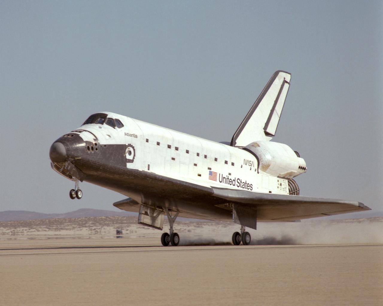
NASA's Space Shuttle Atlantis touched down on the lakebed runway at Edwards Air Force Base in California's Mojave Desert Tuesday, 3 December 1985 at 1:33:49 p.m. Pacific Standard Time, concluding the STS 61-B international mission. The eight-day mission successfully deployed three communications satellites including the Mexican Morelos B, the Australian Aussat 2 and an RCA Satcom K-2 satellite. In addition, two spacewalks were performed to experiment with construction of structures in space. Crew of the 61-B mission included Commander Brewster H. Shaw, Jr.; Pilot Bryan D. O'Connor; Mission Specialists Mary L. Cleave, Sherwood C. Spring and Jerry L. Ross; and Payload Specialists Rudolfo Neri Vela of Mexico and Charles Walker of McDonnell Douglas Astronautics Co.
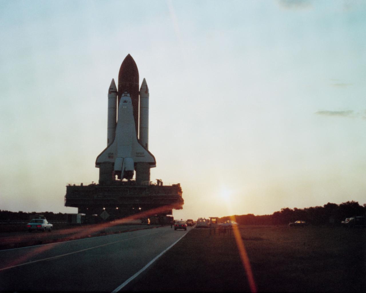
S86-41700 (19 May 1984) --- The Space Shuttle Discovery moves towards Pad A on the crawler transporter for its maiden flight. Discovery will be launched on its first mission no earlier than June 19, 1984. Flight 41-D will carry a crew of six; Commander Henry Hartsfield, Pilot Mike Coats, Mission Specialists Dr. Judith Resnik, Dr. Steven Hawley and Richard Mullane and Payload Specialist Charles Walker. Walker is the first payload specialist to fly aboard a space shuttle. He will be running the materials processing device developed by McDonnell Douglas as part of its Electrophoresis Operations in Space project. Mission 41-D is scheduled to be a seven-day flight and to land at Edwards Air Force Base in California. The Syncom IV-1 (LEASAT) will be deployed from Discovery's cargo bay and the OAST-1, Large Format Camera, IMAX and Cinema 360 cameras will be aboard.

McDonnell Douglas-SPACEHAB technicians oversee the move of a Russian-made oxygen generator to a SPACEHAB Double Module, at rear, in the SPACEHAB Payload Processing Facility. In foreground, from left, are Marc Tuttle, Dan Porter and Mike Vawter. The oxygen generator, manufactured in Russia by RSC Energia, will be carried aboard the Space Shuttle Atlantis on Mission STS-84 for the Shuttle’s scheduled docking with the Russian Space Station Mir next month. The nearly 300-pound generator will replace one of two Mir units that have been malfunctioning recently. The generator functions by electrolysis, which separates water into its oxygen and hydrogen components. The hydrogen is vented and the oxygen is used for breathing by the Mir crew. The generator is 4.2 feet in length and 1.4 feet in diameter. STS-84, which is planned to include a Mir crew exchange of astronaut C. Michael Foale for Jerry M. Linenger, is targeted for a May 15 liftoff
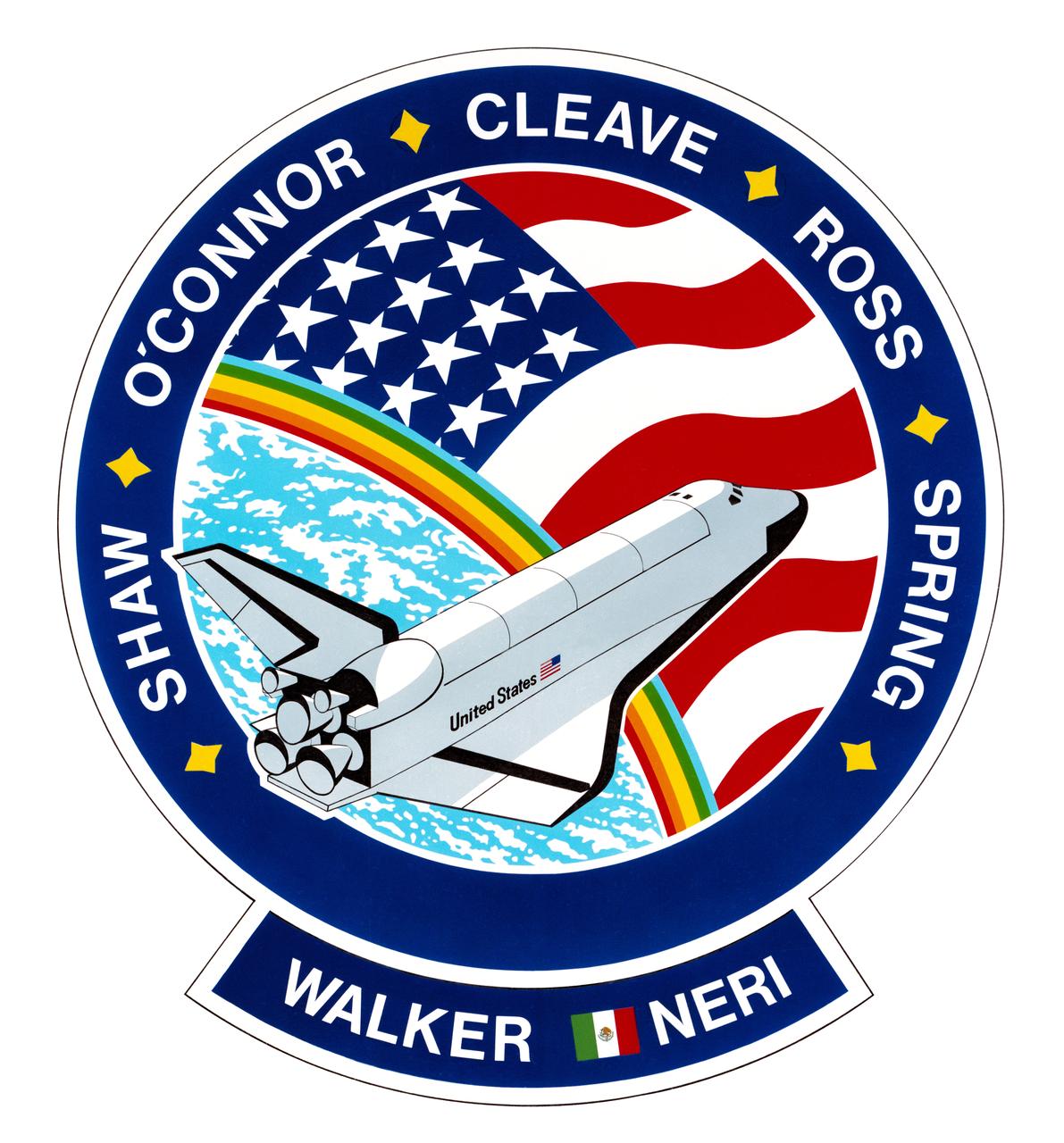
S85-36635 (October 1985) --- This is the insignia designed by the STS-61B crew members to represent their November 1985 mission aboard the space shuttle Atlantis, depicted here in Earth orbit, making only its second spaceflight. The design is surrounded by the surnames of the seven crew members. They are astronauts Brewster Shaw Jr., commander; Bryan D. O'Conner, pilot; Mary L. Cleave, Jerry L. Ross and Sherwood C. Spring, all mission specialists; and payload specialists Charles D. Walker, representing McDonnell Douglas, and Rodolfo Neri, representing Morelos of Mexico (note flag). The NASA insignia design for space shuttle flights is reserved for use by the astronauts and for other official use as the NASA Administrator may authorize. Public availability has been approved only in the forms of illustrations by the various news media. When and if there is any change in this policy, which is not anticipated, the change will be publicly announced. Photo credit: NASA
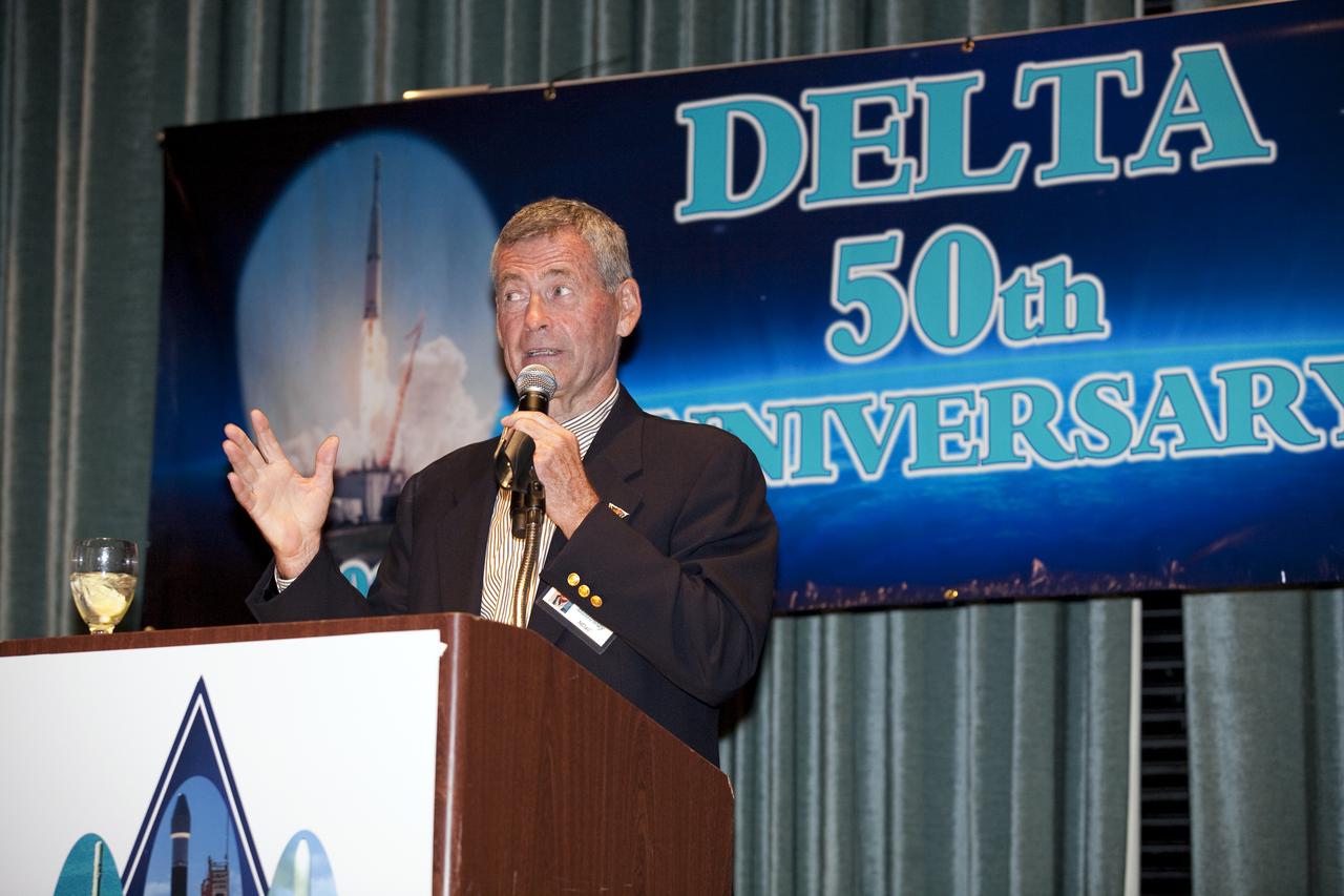
CAPE CANAVERAL, Fla. - Lyle Holloway, former director of launch sites originally for McDonnell Douglas, helps NASA, the U.S. Air Force, United Launch Alliance, Boeing, Pratt and Whitney Rocketdyne, Aerojet and the NASA Alumni League celebrate the Delta expendable launch vehicle program's 50th anniversary at the Radisson Resort in Cape Canaveral, Fla., on May 16. NASA launched the first Delta rocket, which only was intended to be an interim launch vehicle, on May 13, 1960. A half-century later, more than 300 Delta rockets have launched to place crucial weather and environmental satellites into Earth orbit. The vehicles also have sent spacecraft on missions to other planets and comets, and to study the universe. Currently, the Delta II and Delta IV are in use by NASA's Launch Services Program based at Kennedy Space Center in Florida, and are launched by United Launch Alliance. Photo credit: NASA_Amanda Diller
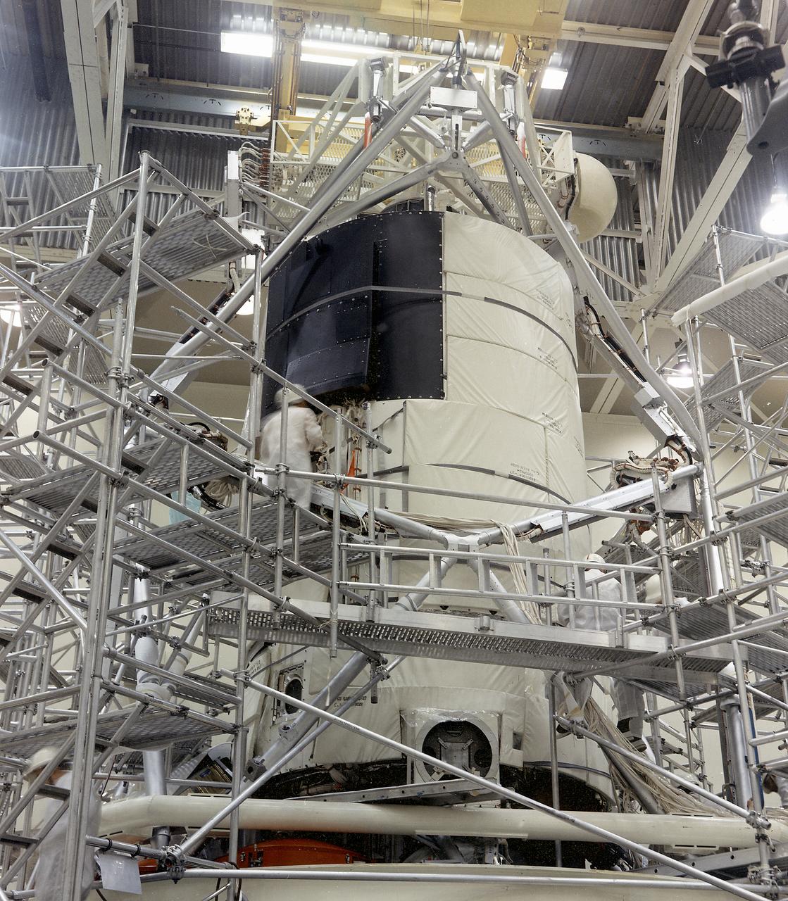
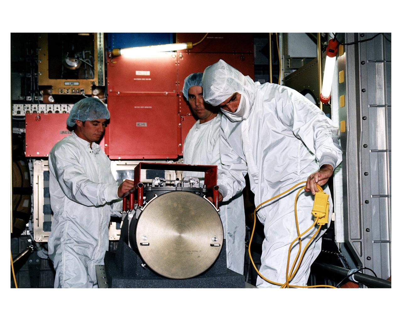
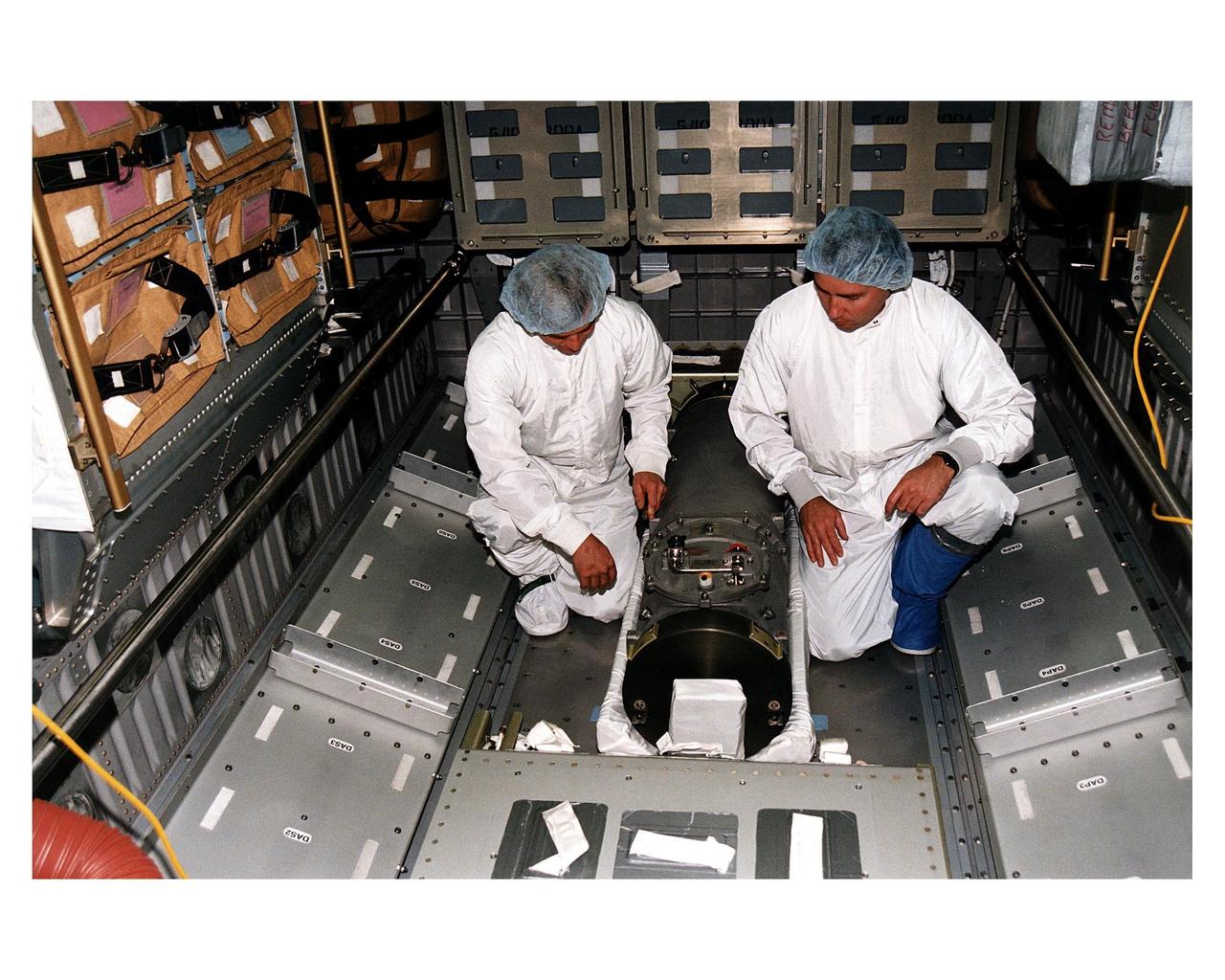
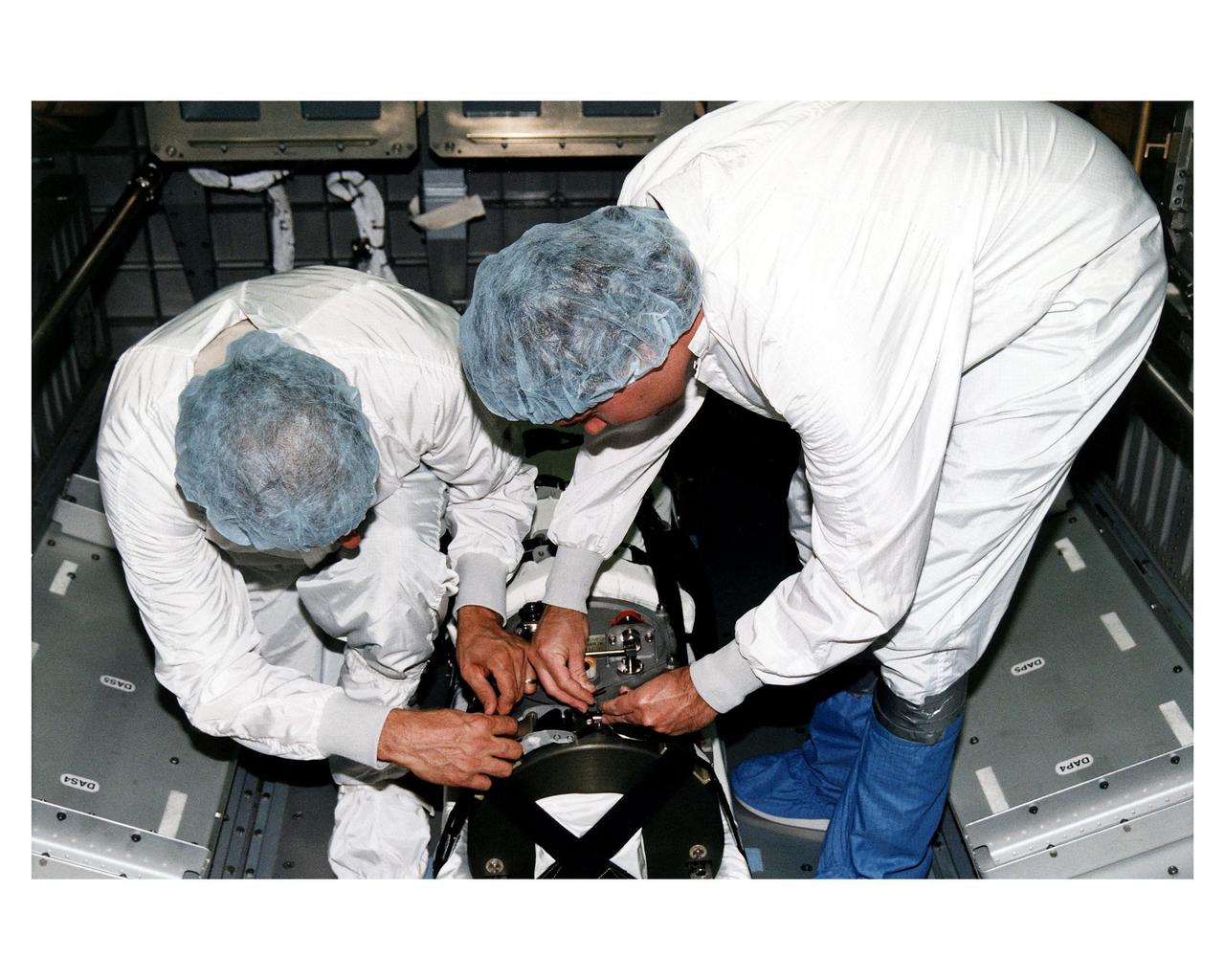
This photograph shows the flight article of the Airlock Module (AM)/Multiple Docking Adapter (MDA) assembly being readied for testing in a clean room at the McDornell Douglas Plant in St. Louis, Missouri. Although the AM and the MDA were separate entities, they were in many respects simply two components of a single module. The AM enabled crew members to conduct extravehicular activities outside Skylab as required for experiment support. Oxygen and nitrogen storage tanks needed for Skylab's life support system were mounted on the external truss work of the AM. Major components in the AM included Skylab's electric power control and distribution station, environmental control system, communication system, and data handling and recording systems. The MDA, forward of the AM, provided docking facilities for the Command and Service Module. It also accommodated several experiment systems, among them the Earth Resource Experiment Package, the materials processing facility, and the control and display console needed for the Apollo Telescope Mount solar astronomy studies. The AM was built by McDonnell Douglas and the MDA was built by Martin Marietta. The Marshall Space Flight Center was responsible for the design and development of the Skylab hardware and experiment management.

This is an illustration of the Space Base concept. In-house work of the Marshall Space Flight Center, as well as a Phase B contract with the McDornel Douglas Astronautics Company, resulted in a preliminary design for a space station in 1969 and l970. The Marshall-McDonnel Douglas approach envisioned the use of two common modules as the core configuration of a 12-man space station. Each common module was 33 feet in diameter and 40 feet in length and provided the building blocks, not only for the space station, but also for a 50-man space base. Coupled together, the two modules would form a four-deck facility: two decks for laboratories and two decks for operations and living quarters. Zero-gravity would be the normal mode of operation, although the station would have an artificial-gravity capability. This general-purpose orbital facility was to provide wide-ranging research capabilities. The design of the facility was driven by the need to accommodate a broad spectrum of activities in support of astronomy, astrophysics, aerospace medicine, biology, materials processing, space physics, and space manufacturing. To serve the needs of Earth observations, the station was to be placed in a 242-nautical-mile orbit at a 55-degree inclination. An Intermediate-21 vehicle (comprised of Saturn S-IC and S-II stages) would have launched the station in 1977.
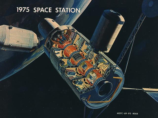
This picture illustrates a concept of a 33-Foot-Diameter Space Station Leading to a Space Base. In-house work of the Marshall Space Flight Center, as well as a Phase B contract with the McDornel Douglas Astronautics Company, resulted in a preliminary design for a space station in 1969 and l970. The Marshall-McDonnel Douglas approach envisioned the use of two common modules as the core configuration of a 12-man space station. Each common module was 33 feet in diameter and 40 feet in length and provided the building blocks, not only for the space station, but also for a 50-man space base. Coupled together, the two modules would form a four-deck facility: two decks for laboratories and two decks for operations and living quarters. Zero-gravity would be the normal mode of operation, although the station would have an artificial gravity capability. This general-purpose orbital facility was to provide wide-ranging research capabilities. The design of the facility was driven by the need to accommodate a broad spectrum of activities in support of astronomy, astrophysics, aerospace medicine, biology, materials processing, space physics, and space manufacturing. To serve the needs of Earth observations, the station was to be placed in a 242-nautical-mile orbit at a 55-degree inclination. An Intermediate-21 vehicle (comprised of Saturn S-IC and S-II stages) would have launched the station in 1977.
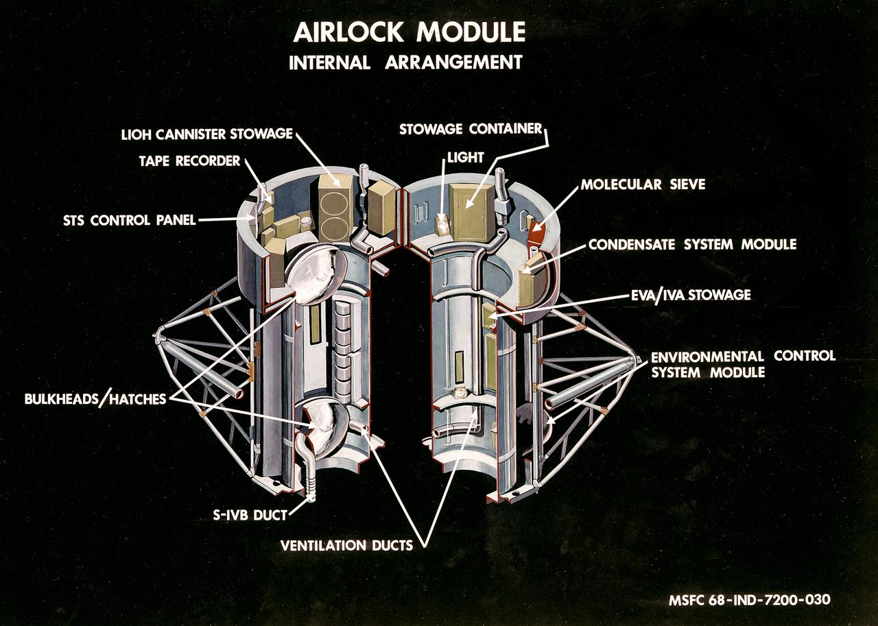
This illustration is a cutaway view of the internal arrangement of the Airlock Module (AM). The aft end of the Docking Adapter mated to the AM, and served as the environmental, electrical, and communications control center. The docking adapter also contained the port through which the astronauts exited to perform extravehicular activity. The AM contained a turnel section through which Skylab crewmen could move between the workshop and the forward end of the airlock. It was encircled, for part of its length, at its aft end by the fixed Airlock Shroud (FAS), that had the same diameter as the workshop (22 feet) and was attached to the workshop's forward end. High pressure containers for oxygen and nitrogen providing Skylab's atmosphere, were mounted in the annular space between the outside of the tunnel and the inside of the shroud. The forward end of the FAS was the base on which the tubular structure supporting the solar observatory was mounted. Many of the supplies, and most of the control systems for Skylab were located in the AM; this module could well be the "utility center" of the Skylab cluster. McDonnell Douglas fabricated the module with close Marshall Space Flight Center's involvement in design, development, and test activities.
This artist's concept is a cutaway illustration of the Skylab Airlock Module and its characteristics. The aft end of the Docking Adapter mated to the Airlock Module (AM), and served as the environmental, electrical, and communications control center. The docking adapter also contained the port through which the astronauts exited to perform extravehicular activity. The AM contained a turnel section through which Skylab crewmen could move between the workshop and the forward end of the airlock. It was encircled, for part of its length, at its aft end by the fixed Airlock Shroud (FAS), that had the same diameter as the workshop (22 feet) and was attached to the workshop's forward end. High pressure containers for oxygen and nitrogen providing Skylab's atmosphere, were mounted in the annular space between the outside of the tunnel and the inside of the shroud. The forward end of the FAS was the base on which the tubular structure supporting the solar observatory was mounted. Many of the supplies, and most of the control systems for Skylab were located in the AM; this module could well be the "utility center" of the Skylab cluster. McDonnell Douglas fabricated the module with close Marshall Space Flight Center's involvement in design, development, and test activities.
KENNEDY SPACE CENTER, FLA. -- McDonnell Douglas-SPACEHAB technicians look over a Russian-made oxygen generator which has just been placed on the floor of a SPACEHAB Double Module being prepared for flight on Space Shuttle Mission STS-84. The module is being processed in the SPACEHAB Payload Processing Facility just outside of Gate 1 on Cape Canaveral Air Station. The Space Shuttle Atlantis will transport the oxygen generator to the Russian Space Station Mir to replace one of two Mir units that have been malfunctioning recently. The nearly 300-pound generator functions by electrolysis, which separates water into its oxygen and hydrogen components. The hydrogen is vented and the oxygen is used for breathing by the Mir crew. The generator is 4.2 feet long with a diameter of 1.4 feet. STS-84, which is planned to include a Mir crew exchange of astronaut C. Michael Foale for Jerry M. Linenger, is targeted for a May 15 launch. It will be the sixth Shuttle-Mir docking
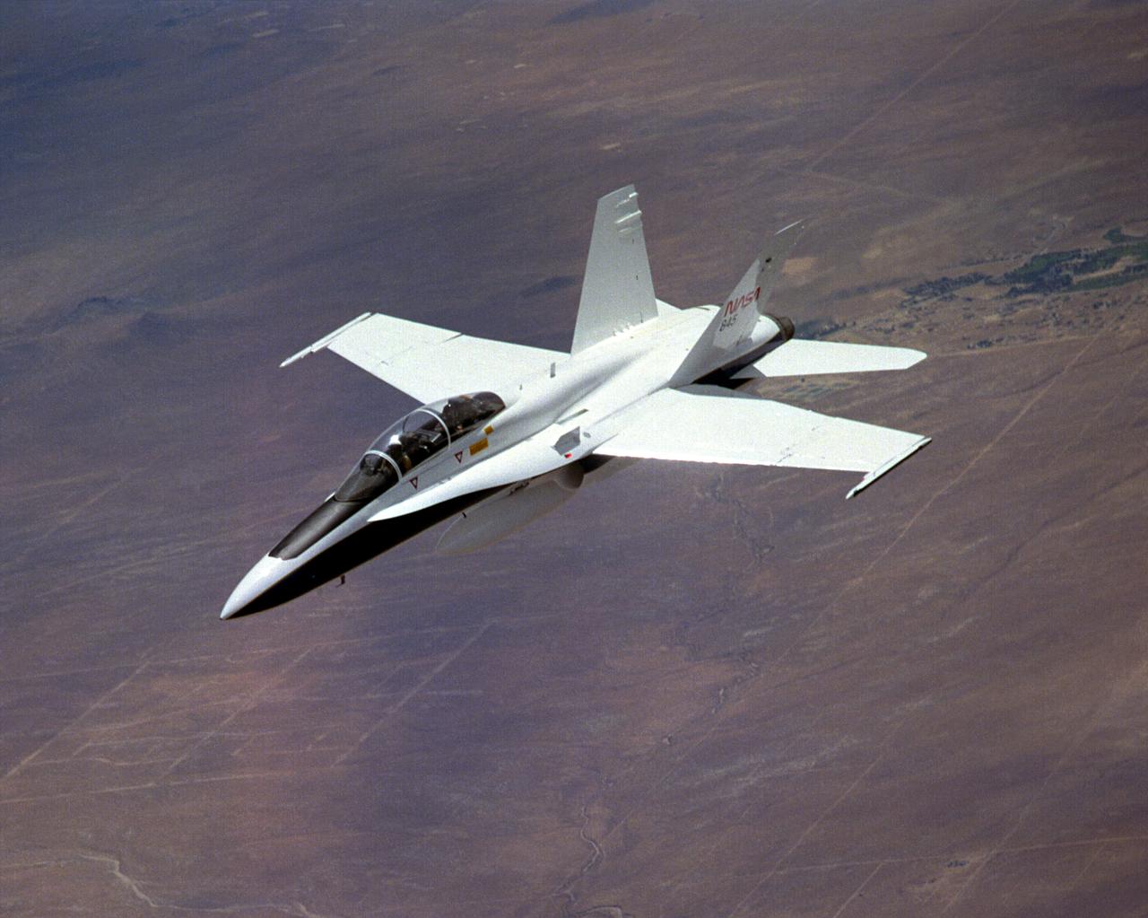
The National Aeronautics and Space Administration's Systems Research Aircraft (SRA), a highly modified F-18 jet fighter, during a research flight. The former Navy aircraft was flown by NASA's Dryden Flight Research Center at Edwards Air Force Base, California, to evaluate a number of experimental aerospace technologies in a multi-year, joint NASA/DOD/industry program. Among the more than 20 experiments flight-tested were several involving fiber optic sensor systems. Experiments developed by McDonnell-Douglas and Lockheed-Martin centered on installation and maintenace techniques for various types of fiber-optic hardware proposed for use in military and commercial aircraft, while a Parker-Hannifin experiment focused in alternative fiber-optic designs for position measurement sensors as well as operational experience in handling optical sensor systems. Other experiments flown on this testbed aircraft included electronically-controlled control surface actuators, flush air data collection systems, "smart" skin antennae and laser-based systems. Incorporation of one or more of these technologies in future aircraft and spacecraft could result in signifigant savings in weight, maintenance and overall cost.
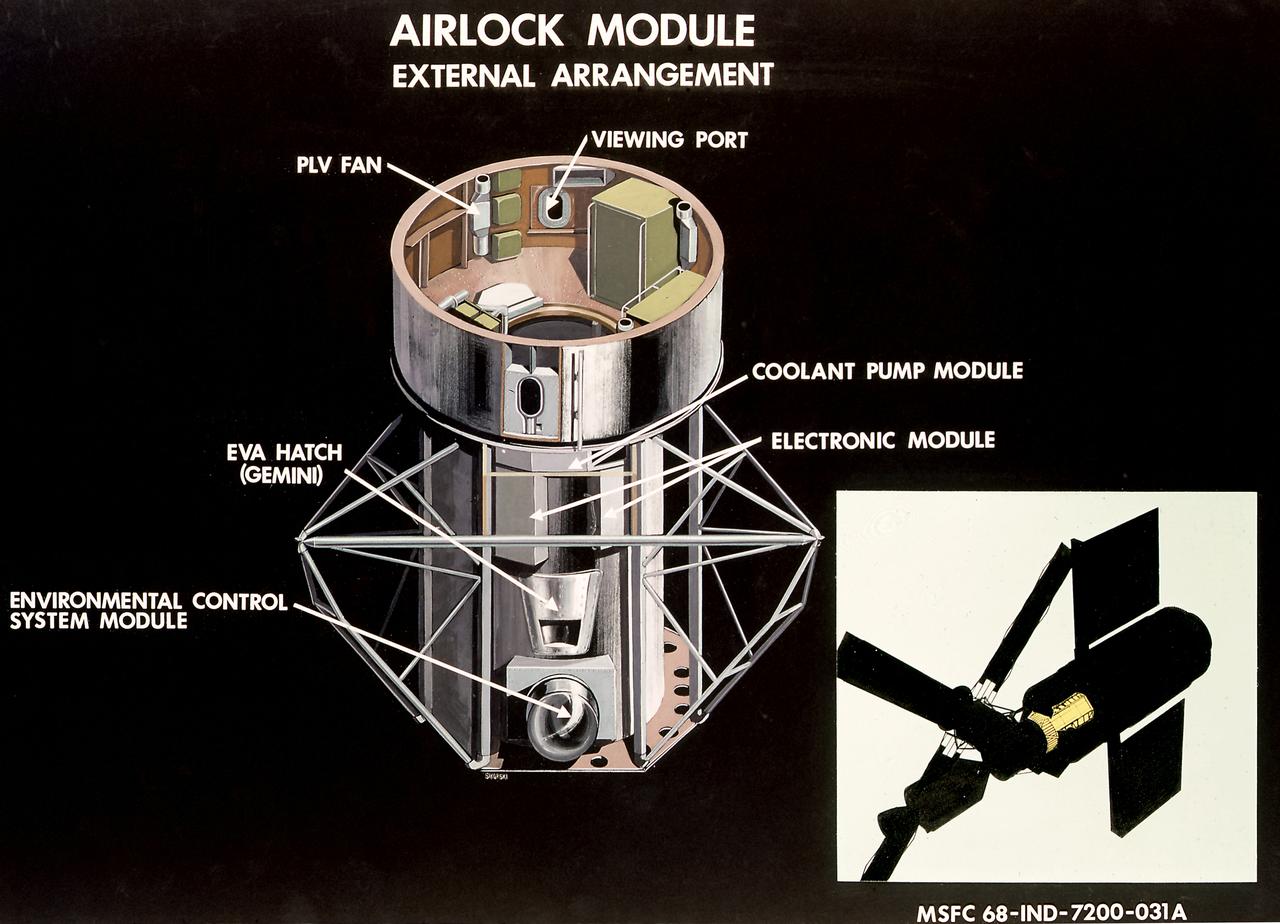
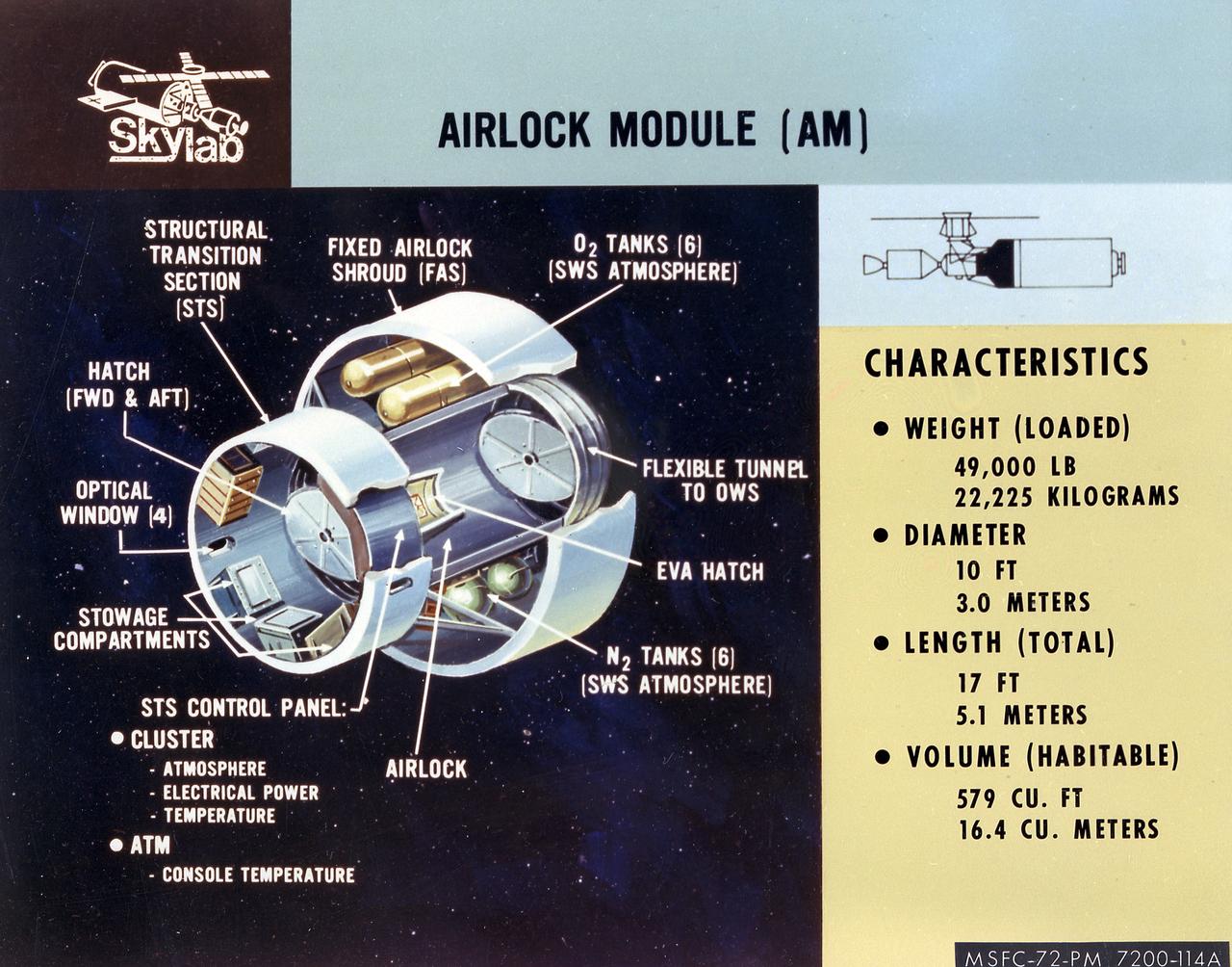
This illustration is a cutaway view of the external arrangement of the Airlock Module (AM). The aft end of the Docking Adapter mated to the AM, and served as the environmental, electrical, and communications control center. The docking adapter also contained the port through which the astronauts exited to perform extravehicular activity. The AM contained a turnel section through which Skylab crewmen could move between the workshop and the forward end of the airlock. It was encircled, for part of its length, at its aft end by the fixed Airlock Shroud (FAS), that had the same diameter as the workshop (22 feet) and was attached to the workshop's forward end. High pressure containers for oxygen and nitrogen providing Skylab's atmosphere, were mounted in the annular space between the outside of the tunnel and the inside of the shroud. The forward end of the FAS was the base on which the tubular structure supporting the solar observatory was mounted. Many of the supplies, and most of the control systems for Skylab were located in the AM; this module could well be the "utility center" of the Skylab cluster. McDonnell Douglas fabricated the module with close Marshall Space Flight Center's involvement in design, development, and test activities.
KENNEDY SPACE CENTER, FLA. -- McDonnell Douglas-SPACEHAB technicians strap in place a Russian-made oxygen generator on the floor of a SPACEHAB Double Module, being prepared for flight in the SPACEHAB Payload Processing Facility. From left, are Mark Halavin and Marc Tuttle. The oxygen generator, manufactured in Russia by RSC Energia, will be carried aboard the Space Shuttle Atlantis on Mission STS-84 for the Shuttle’s scheduled docking with the Russian Space Station Mir next month. The nearly 300-pound generator will replace one of two Mir units that have been malfunctioning recently. The generator functions by electrolysis, which separates water into its oxygen and hydrogen components. The hydrogen is vented and the oxygen is used for breathing by the Mir crew. The generator is 4.2 feet in length and 1.4 feet in diameter. STS-84, which is planned to include a Mir crew exchange of astronaut C. Michael Foale for Jerry M. Linenger, is targeted for a May 15 liftoff. It will be the sixth Shuttle-Mir docking
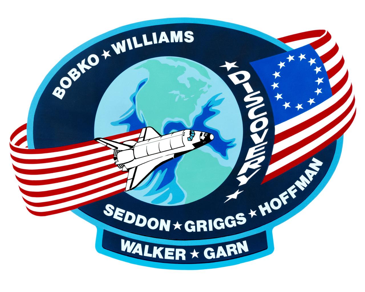
S85-28989 (March 1985) --- The dominant features of the STS-51D emblem are an orbit formed by a Colonial American flag and a space shuttle. The flag in orbit signifies the U.S. flag to indicate that it comes from this country and the American people. The original 13-star flag is used to symbolize a continuity of technical achievement and progress since colonial times. The name Discovery preceding the flag represents the spirit of Discovery and exploration of new frontiers which have been a hallmark of American people even before they were formed together as a nation. The crew members are Karol J. Bobko, Donald E. Williams, Rhea Seddon, S. David Griggs and Jeffrey A. Hoffman of NASA; and Charles D. Walker, representing McDonnell Douglas Corporation; and U. S. Senator Jake Garn. The NASA insignia design for space shuttle flights is reserved for use by the astronauts and for other official use as the NASA Administrator may authorize. Public availability has been approved only in the forms of illustrations by the various news media. When and if there is any change in this policy, which is not anticipated, the change will be publicly announced. Photo credit: NASA
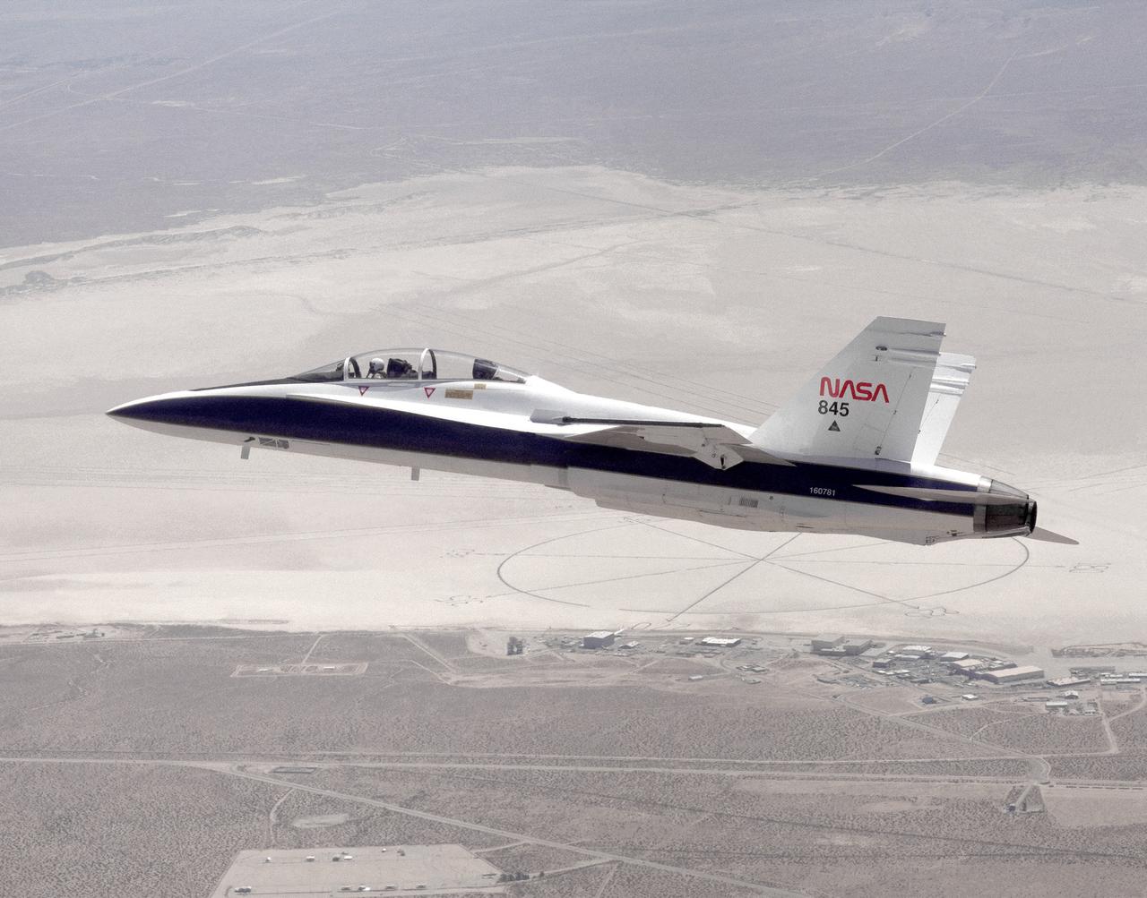
The National Aeronautics and Space Administration's Systems Research Aircraft (SRA), a highly modified F-18 jet fighter, on an early research flight over Rogers Dry Lake. The former Navy aircraft was flown by NASA's Dryden Flight Research Center at Edwards Air Force Base, California, to evaluate a number of experimental aerospace technologies in a multi-year, joint NASA/DOD/industry program. Among the more than 20 experiments flight-tested were several involving fiber optic sensor systems. Experiments developed by McDonnell-Douglas and Lockheed-Martin centered on installation and maintenace techniques for various types of fiber-optic hardware proposed for use in military and commercial aircraft, while a Parker-Hannifin experiment focused on alternative fiber-optic designs for postion measurement sensors as well as operational experience in handling optical sensor systems. Other experiments flown on this testbed aircraft included electronically-controlled control surface actuators, flush air data collection systems, "smart" skin antennae and laser-based systems. Incorporation of one or more of these technologies in future aircraft and spacecraft could result in signifigant savings in weight, maintenance and overall cost.
KENNEDY SPACE CENTER, FLA. -- McDonnell Douglas-SPACEHAB technicians oversee the move of a Russian-made oxygen generator to a SPACEHAB Double Module, at rear, in the SPACEHAB Payload Processing Facility. With faces visible in center foreground, from left, are Mark Halavin and Marc Tuttle; Mike Vawter is at far right. The oxygen generator, manufactured in Russia by RSC Energia, will be carried aboard the Space Shuttle Atlantis on Mission STS-84 for the Shuttle’s scheduled docking with the Russian Space Station Mir next month. The nearly 300-pound generator will replace one of two Mir units that have been malfunctioning recently. The generator functions by electrolysis, which separates water into its oxygen and hydrogen components. The hydrogen is vented and the oxygen is used for breathing by the Mir crew. The generator is 4.2 feet in length and 1.4 feet in diameter. STS-84, which is planned to include a Mir crew exchange of astronaut C. Michael Foale for Jerry M. Linenger, is targeted for a May 15 liftoff. It will be the sixth Shuttle-Mir docking
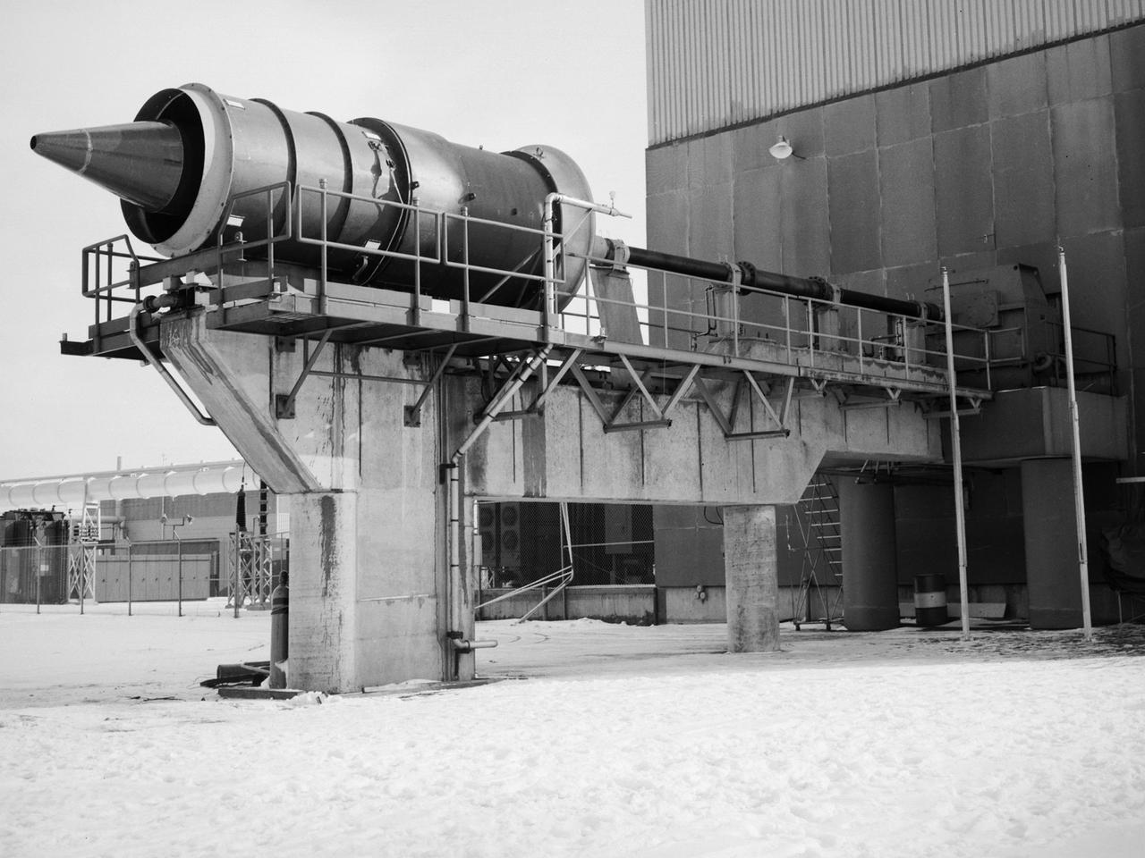
The Fan Noise Test Facility built at the Lewis Research Center to obtain far-field noise data for the National Aeronautics and Space Administration (NASA) and General Electric Quiet Engine Program. The engine incorporated existing noise reduction methods into an engine of similar power to those that propelled the Boeing 707 or McDonnell-Douglas DC-8 airliner. The new the low-bypass ratio turbofan engines of the 1960s were inherently quieter than their turbojet counterparts, researchers had a better grasp of the noise generation problem, and new acoustic technologies had emerged. Lewis contracted General Electric in 1969 to build and aerodynamically test three experimental engines with 72-inch diameter fans. The engines were then brought to Lewis and tested with an acoustically treated nacelle. This Fan Noise Test Facility was built off of the 10- by 10-Foot Supersonic Wind Tunnel’s Main Compressor and Drive Building. Lewis researchers were able to isolate the fan’s noise during these initial tests by removing the core of the engine. The Lewis test rig drove engines to takeoff tip speeds of 1160 feet per second. The facility was later used to test a series of full-scale model fans and fan noise suppressors to be used with the quiet engine. NASA researchers predicted low-speed single-stage fans without inlet guide vanes and with large spacing between rotors and stators would be quieter. General Electric modified a TF39 turbofan engine by removing the the outer protion of the fan and spacing the blade rows of the inner portion. The tests revealed that the untreated version of the engine generated less noise than was anticipated, and the acoustically treated nacelle substantially reduced engine noise.
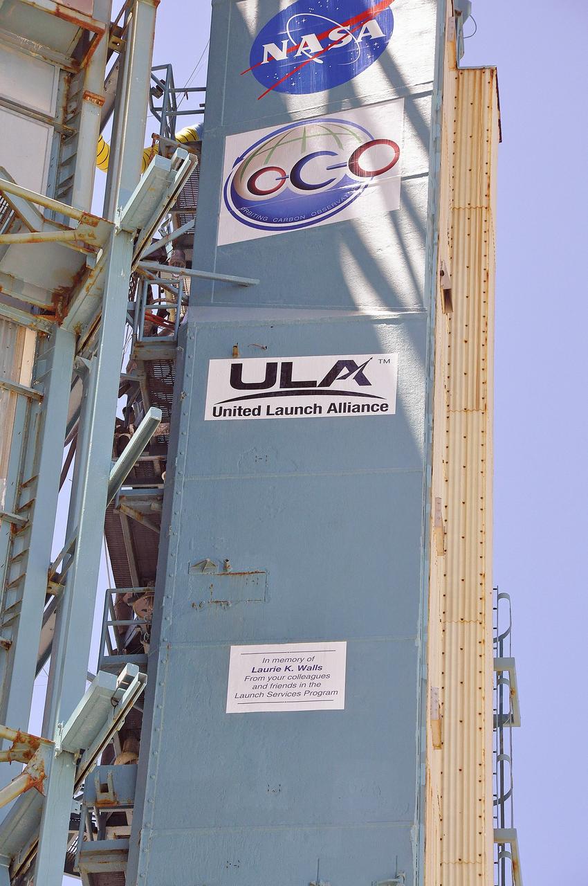
VANDENBERG AIR FORCE BASE, Calif. – A memorial plaque honoring Laurie K. Walls is affixed to the umbilical tower on Space Launch Complex 2 at Vandenberg Air Force Base in California for the launch of NASA's Orbiting Carbon Observatory-2, or OCO-2. Walls, a thermal analysis engineer with the Launch Services Program, or LSP, at NASA's Kennedy Space Center, died June 4. This dedication to Walls from the members of the launch team was read during the OCO-2 countdown commentary: "The OCO-2 mission has special meaning to NASA's Launch Services Program as we have dedicated it to one of our LSP Teammates, Laurie Walls. Laurie began her career over 30 years ago as a thermal engineer for McDonnell Douglas in Huntsville, Alabama, supporting NASA's Marshall Space Flight Center. She moved to Florida in 1985. Shortly after coming to Florida, Laurie became a civil servant working on the Shuttle program return to flight effort post-Challenger. In 1998, Laurie joined the newly formed Launch Services Program as one of the founding members of the flight analysis group. She served in LSP as the thermal discipline expert until her untimely death earlier this month. Laurie worked thermal issues for numerous NASA Delta II and Atlas V missions. Additionally, she provided key thermal support for both Delta II Heavy development and Atlas V Certification. Laurie was an integral member of LSP's family and she was truly dedicated to NASA and the LSP team. She will be greatly missed. We honor Laurie with a special memorial placed on the SLC-2 umbilical tower, and we thank ULA for helping to make this happen." Launch of OCO-2 is scheduled for 5:56 a.m. EDT on July 1. To learn more about NASA's Launch Services Program, visit http://www.nasa.gov/centers/kennedy/launchingrockets/index.html. Photo credit: NASA/Randy Beaudoin
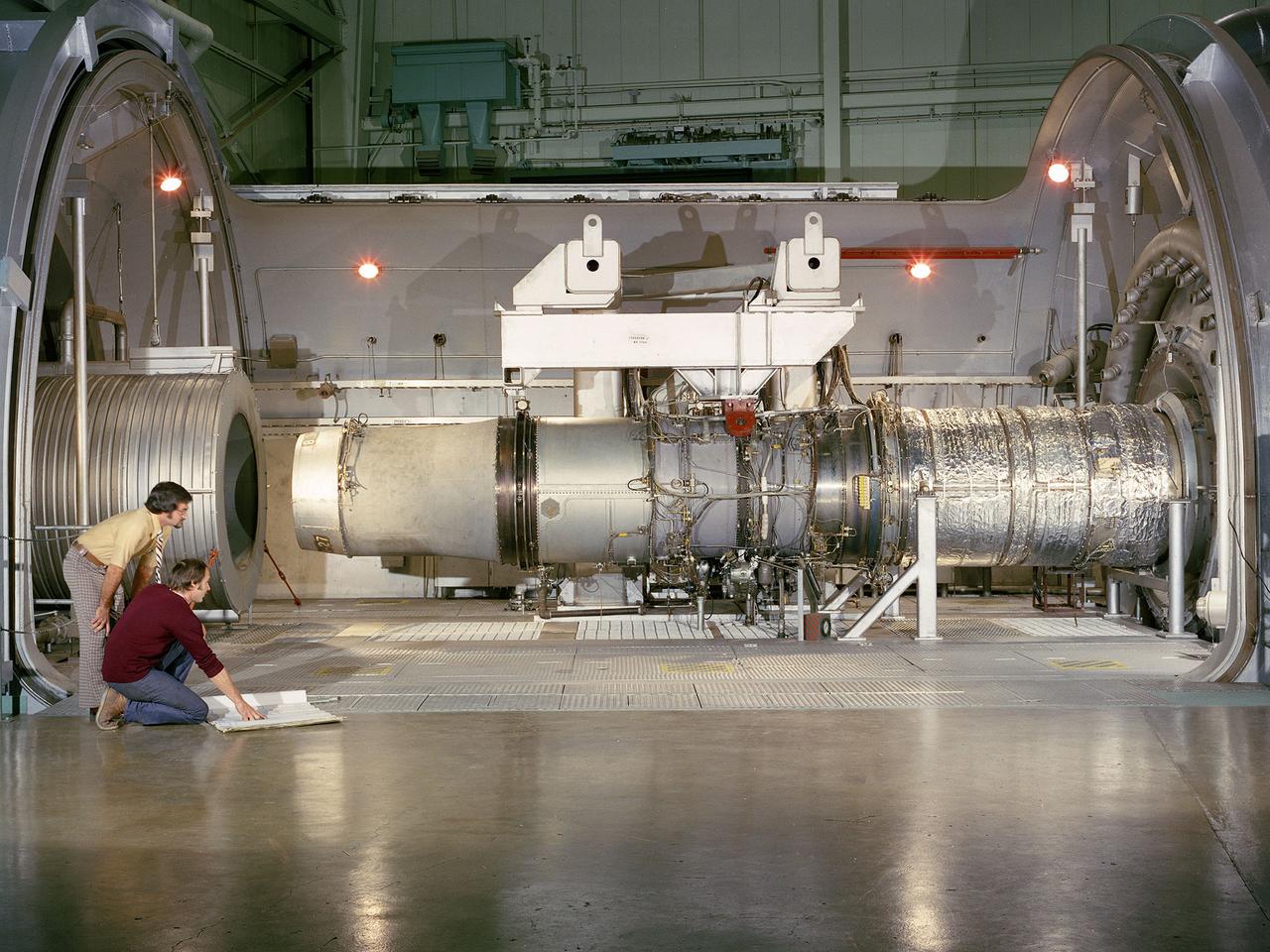
A refanned Pratt and Whitney JT-8D-109 turbofan engine installed in Cell 4 of the Propulsion Systems Laboratory at the National Aeronautics and Space Administration (NASA) Lewis Research Center. NASA Lewis’ Refan Program sought to demonstrate that noise reduction modifications could be applied to existing aircraft engines with minimal costs and without diminishing the engine’s performance or integrity. At the time, Pratt and Whitney’s JT-8D turbofans were one of the most widely used engines in the commercial airline industry. The engines powered Boeing’s 727 and 737 and McDonnell Douglas’ DC-9 aircraft. Pratt and Whitney worked with the airline manufacturers on a preliminary study that verified feasibility of replacing the JT-8D’s two-stage fan with a larger single-stage fan. The new fan slowed the engine’s exhaust, which significantly reduced the amount of noise it generated. Booster stages were added to maintain the proper level of airflow through the engine. Pratt and Whitney produced six of the modified engines, designated JT-8D-109, and performed the initial testing. One of the JT-8D-109 engines, seen here, was tested in simulated altitude conditions in NASA Lewis’ Propulsion Systems Laboratory. The Refan engine was ground-tested on an actual aircraft before making a series of flight tests on 727 and DC-9 aircraft in early 1976. The Refan Program reduced the JT-8D’s noise by 50 percent while increasing the fuel efficiency. The retro-fit kits were estimated to cost between $1 million and $1.7 million per aircraft.
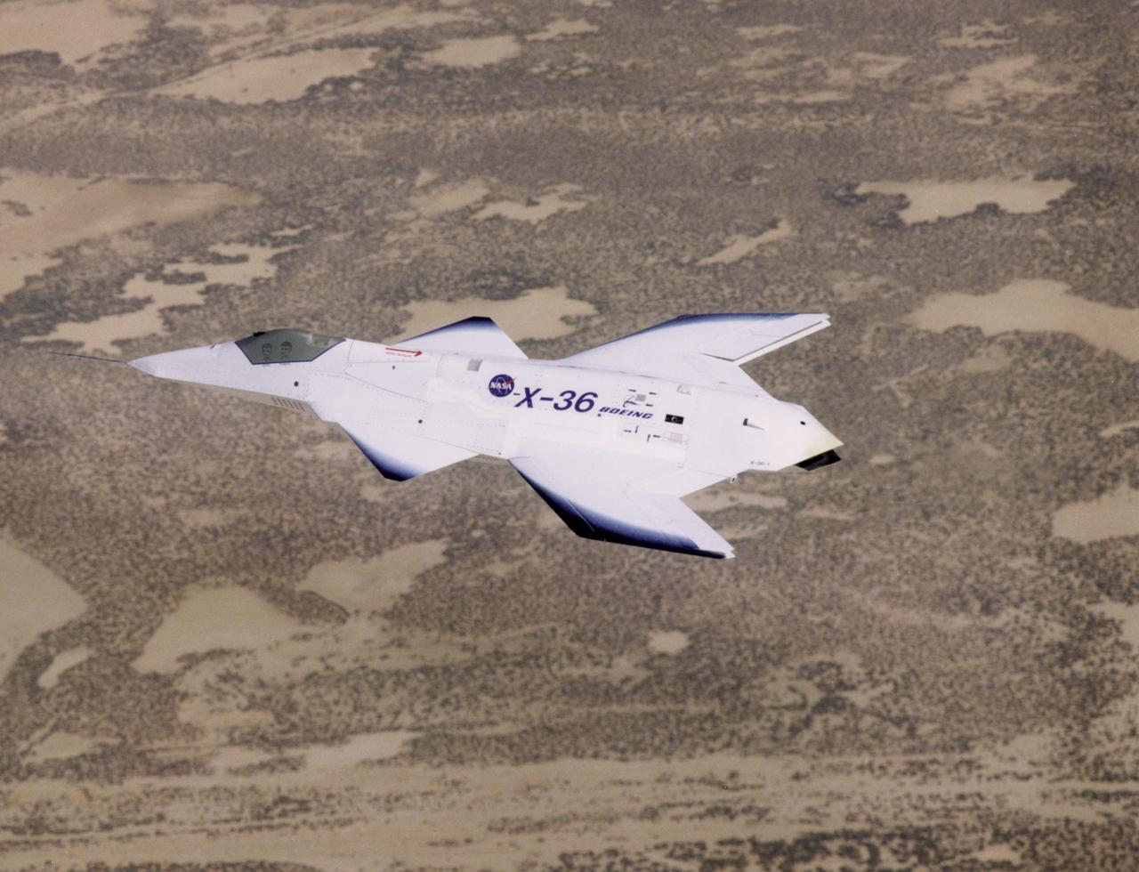
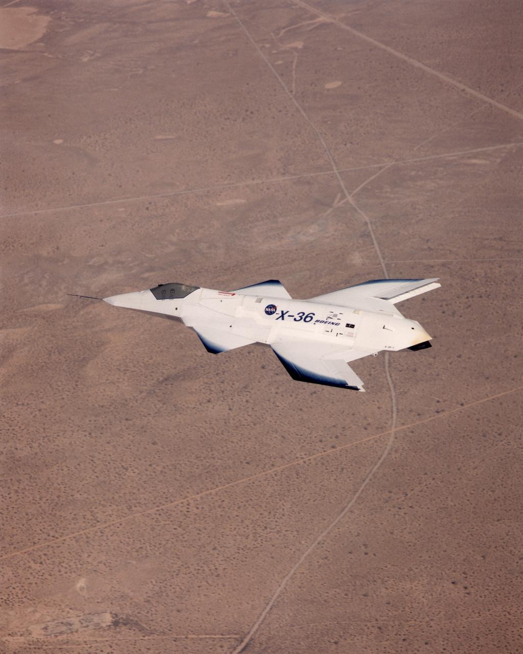
The unusual lines of the X-36 technology demonstrator contrast sharply with the desert floor as the remotely piloted aircraft scoots across the California desert at low altitude during a research flight on October 30, 1997.
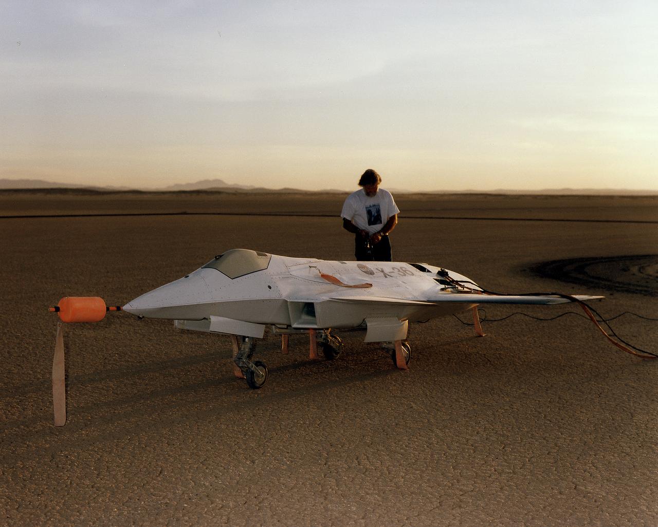
Lit by the rays of the morning sunrise on Rogers Dry Lake, adjacent to NASA's Dryden Flight Research Center, Edwards, California, a technician prepares the remotely-piloted X-36 Tailless Fighter Agility Research Aircraft for its first flight on May 17, 1997.
The tailless X-36 technology demonstrator research aircraft cruises over the California desert at low altitude during a 1997 research flight.
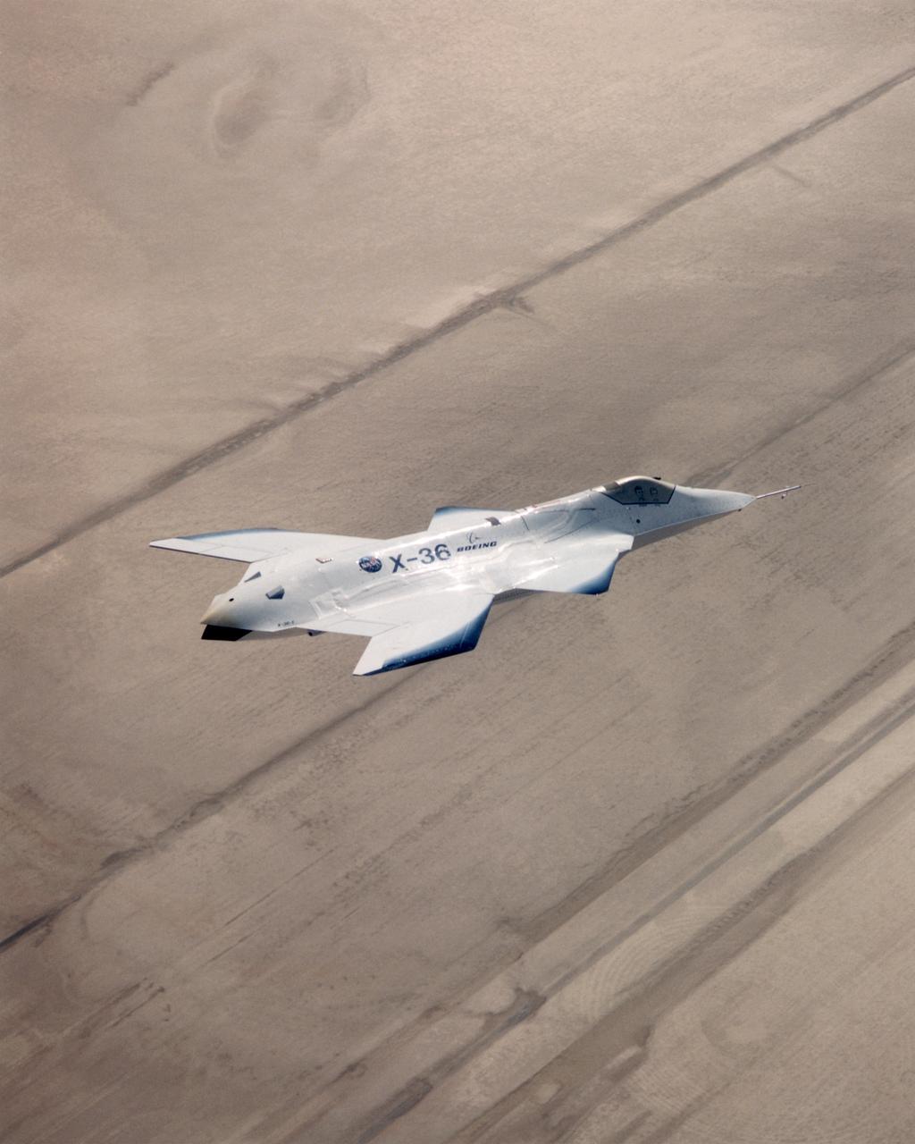
The X-36 technology demonstrator shows off its distinctive shape as the remotely piloted aircraft flies a research mission over the Southern California desert on October 30, 1997.
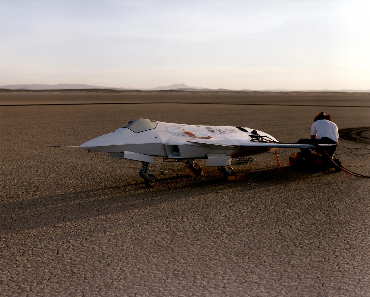
Lit by the rays of the morning sunrise on Rogers Dry Lake, adjacent to NASA's Dryden Flight Research Center, Edwards, California, technicians prepare the remotely-piloted X-36 Tailless Fighter Agility Research Aircraft for its first flight in May 1997.
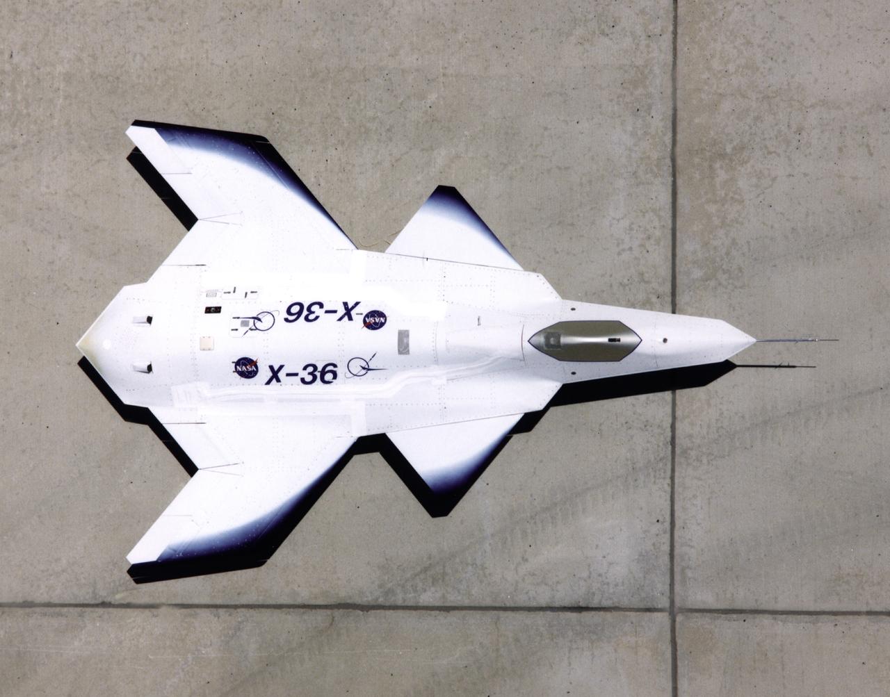
This look-down view of the X-36 Tailless Fighter Agility Research Aircraft on the ramp at NASA’s Dryden Flight Research Center, Edwards, California, clearly shows the unusual wing and canard design of the remotely-piloted aircraft.
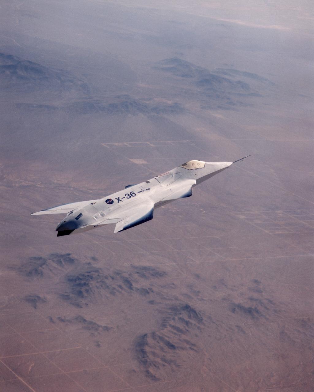
The X-36 technology demonstrator shows off its distinctive shape as the remotely piloted aircraft flies a research mission over the Southern California desert on October 30, 1997.
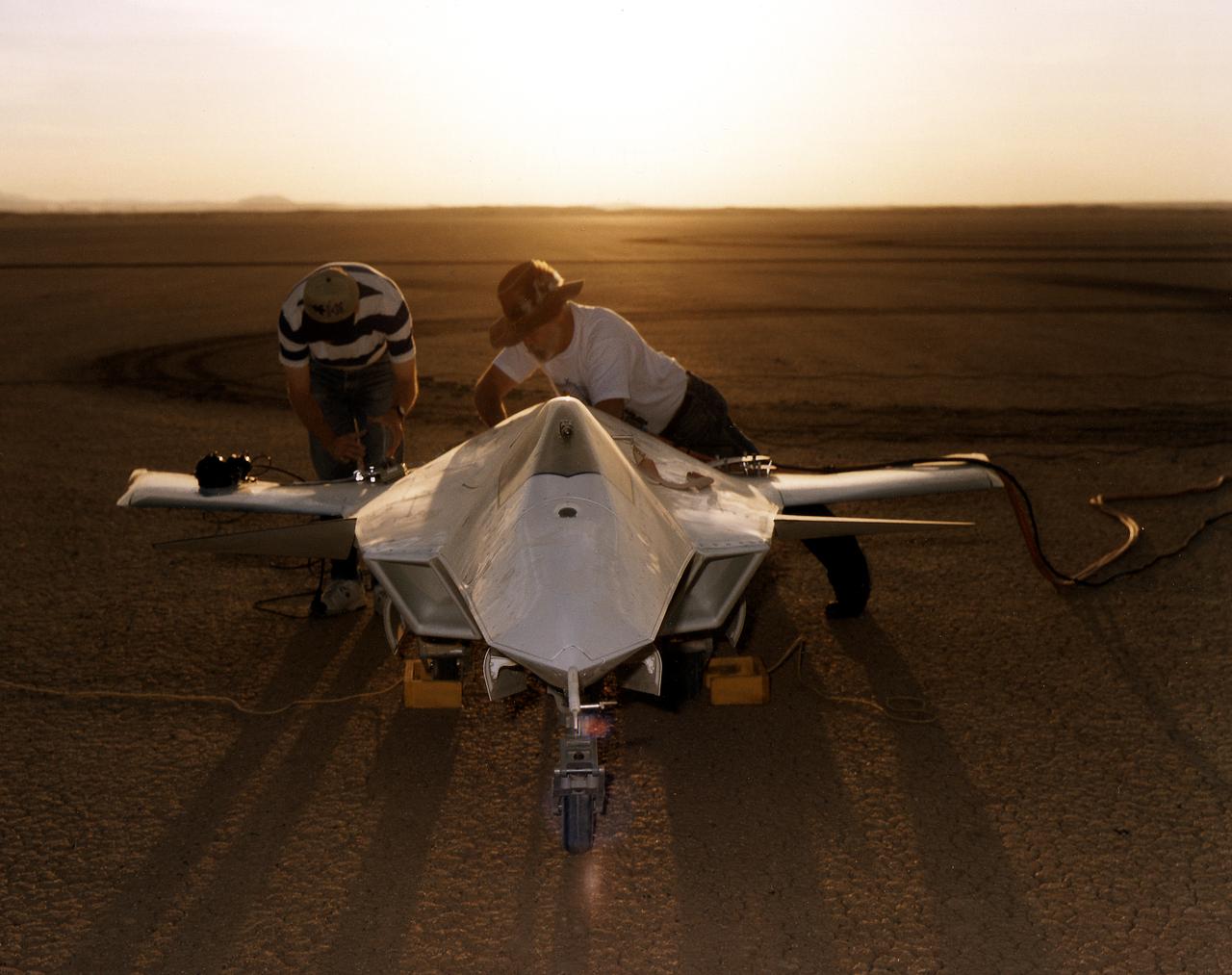
As the sun creeps above the horizon of Rogers Dry Lake at NASA's Dryden Flight Research Center, Edwards, California, technicians make final preparations for the first flight of the X-36 Tailless Fighter Agility Research Aircraft.
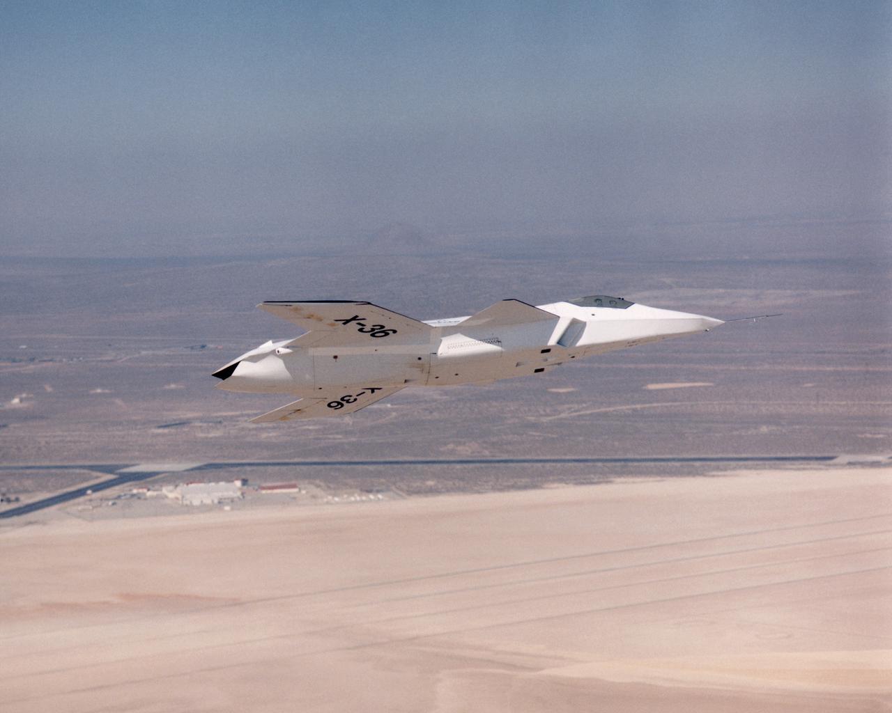
The lack of a vertical tail on the X-36 technology demonstrator is evident as the remotely piloted aircraft flies a low-altitude research flight above Rogers Dry Lake at Edwards Air Force Base in the California desert on October 30, 1997.
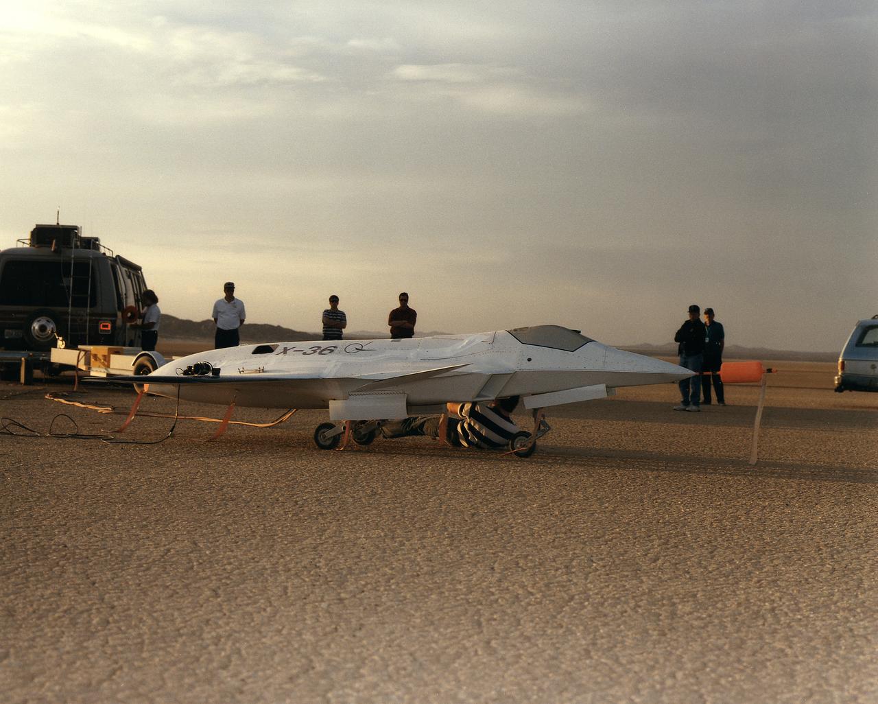
Lit by the rays of the morning sunrise on Rogers Dry Lake, adjacent to NASA's Dryden Flight Research Center, Edwards, California, technicians prepares the remotely-piloted X-36 Tailless Fighter Agility Research Aircraft for its first flight on May 17, 1997.
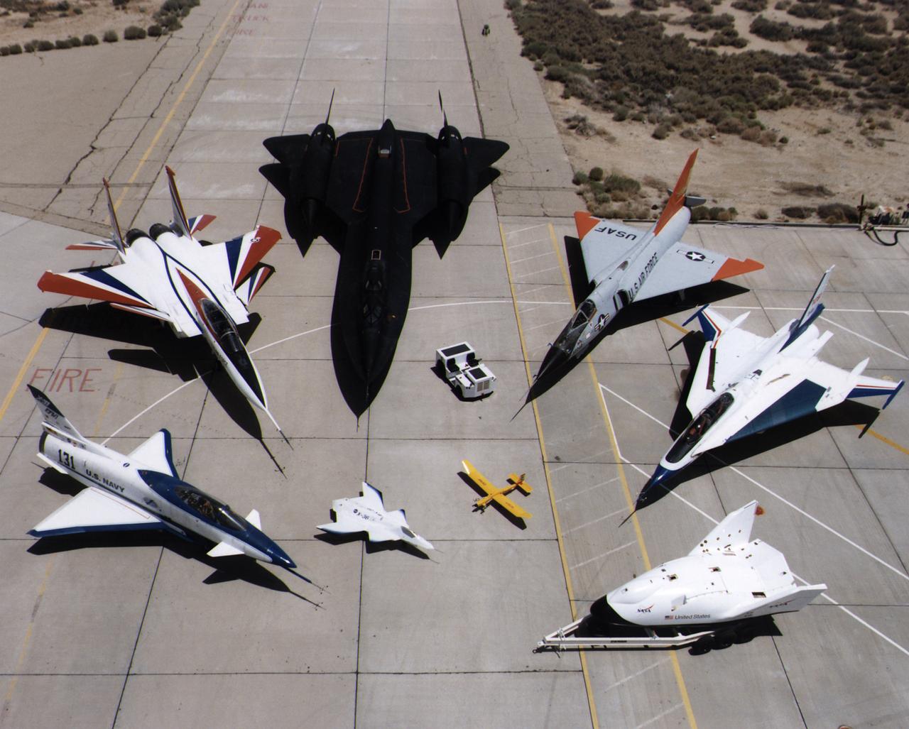
A collection of NASA's research aircraft on the ramp at the Dryden Flight Research Center in July 1997: X-31, F-15 ACTIVE, SR-71, F-106, F-16XL Ship #2, X-38, Radio Controlled Mothership and X-36.