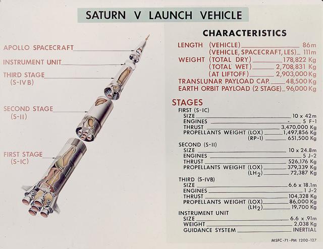
This is a good cutaway diagram of the Saturn V launch vehicle showing the three stages, the instrument unit, and the Apollo spacecraft. The chart on the right presents the basic technical data in clear metric detail. The Saturn V is the largest and most powerful launch vehicle in the United States. The towering, 111 meter, Saturn V was a multistage, multiengine launch vehicle standing taller than the Statue of Liberty. Altogether, the Saturn V engines produced as much power as 85 Hoover Dams. Development of the Saturn V was the responsibility of the Marshall Space Flight Center at Huntsville, Alabama, directed by Dr. Wernher von Braun.

Technicians check out the mounting structure of the 20-metric-ton infrared telescope installed in NASA's Stratospheric Observatory for Infrared Astronomy (SOFIA).
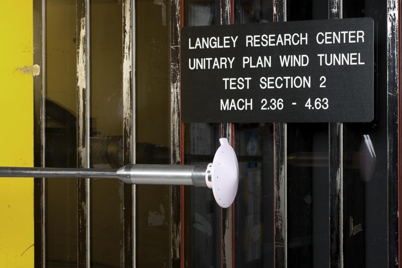
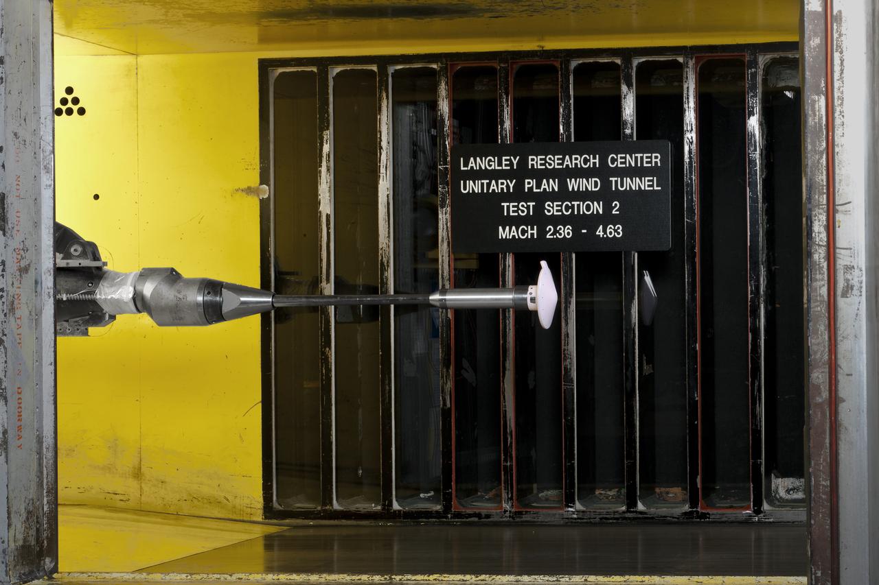
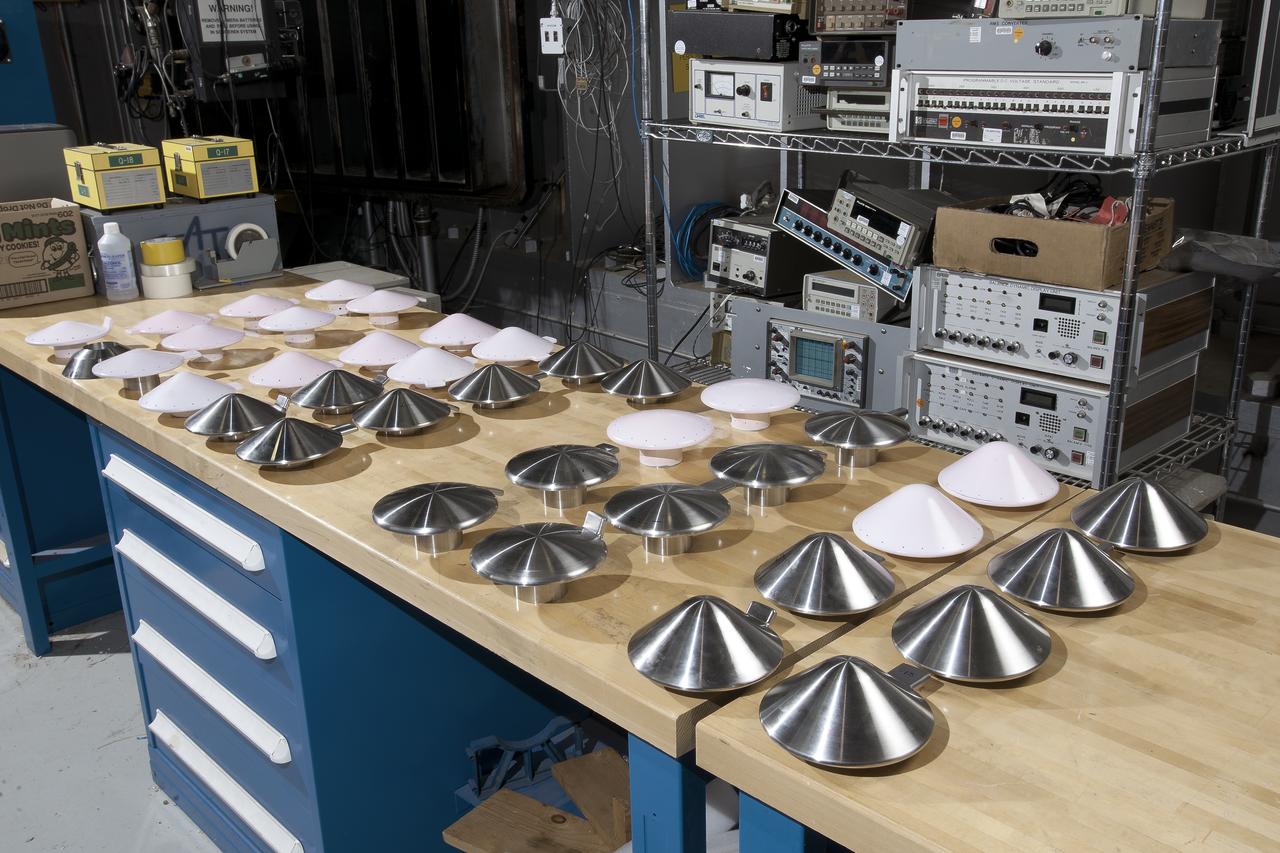
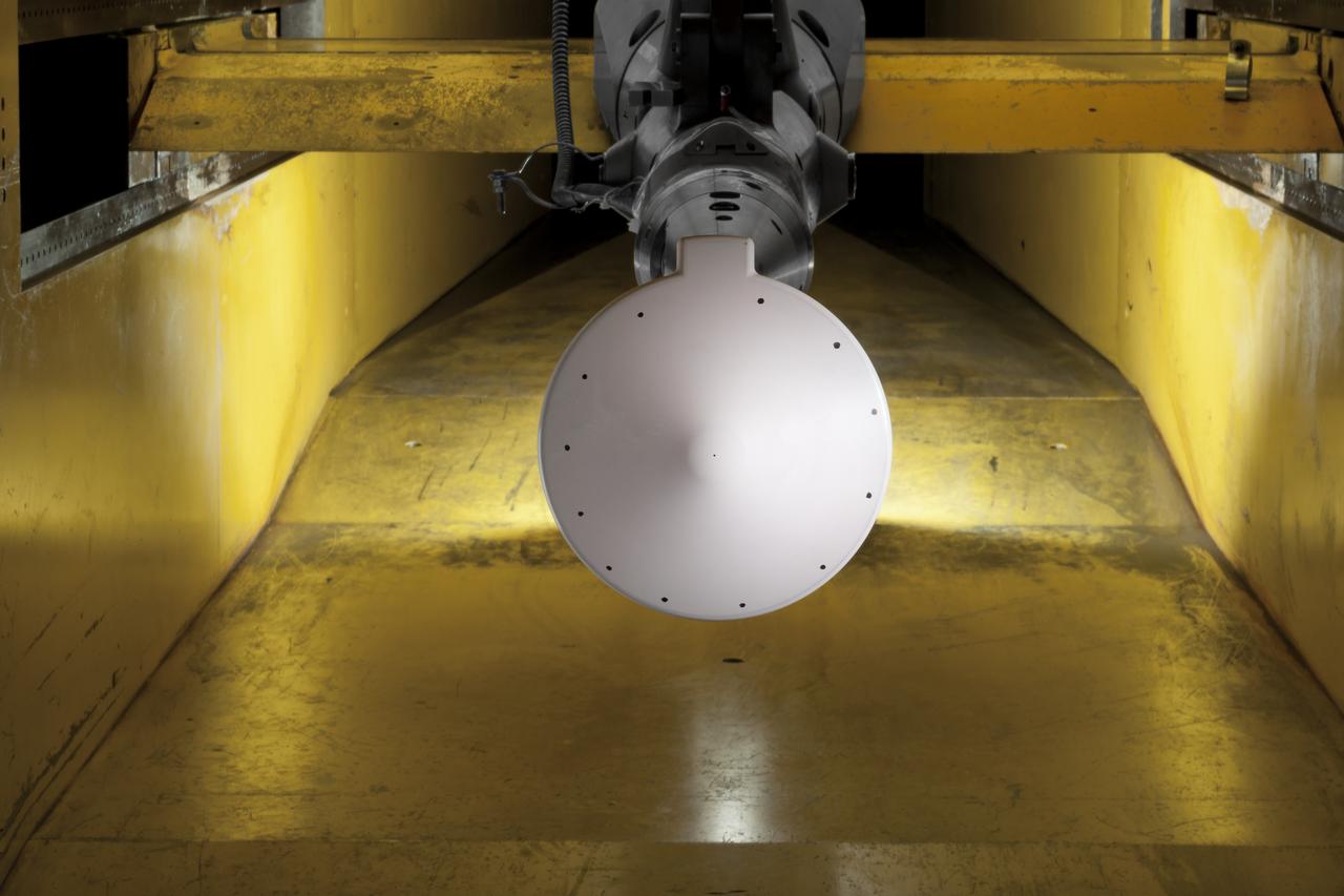
Test 1875 in Unitary Plan Wind Tunnel (UPWT) HIADS TTPM: Trim Tab study on various cone angled heat shields (TTPM) Technology Technical Performance Metric (HIADS) Hypersonic inflatable aerodynamic decelerators
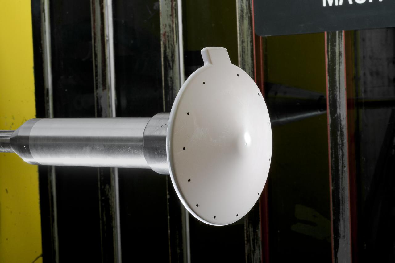
Test 1875 in Unitary Plan Wind Tunnel (UPWT) HIADS TTPM: Trim Tab study on various cone angled heat shields (TTPM) Technology Technical Performance Metric (HIADS) Hypersonic inflatable aerodynamic decelerators
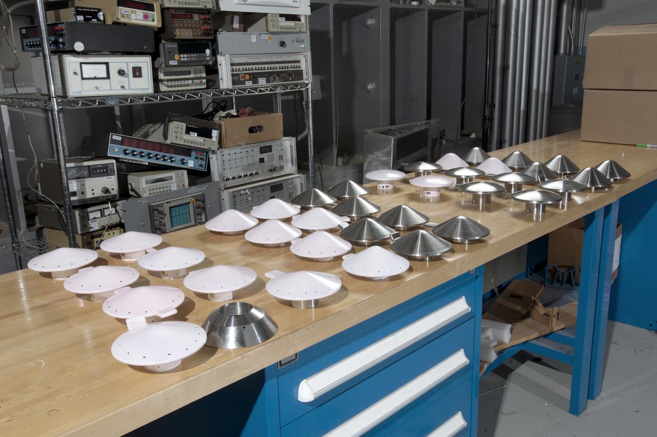
Test 1875 in Unitary Plan Wind Tunnel (UPWT) HIADS TTPM: Trim Tab study on various cone angled heat shields (TTPM) Technology Technical Performance Metric (HIADS) Hypersonic inflatable aerodynamic decelerators
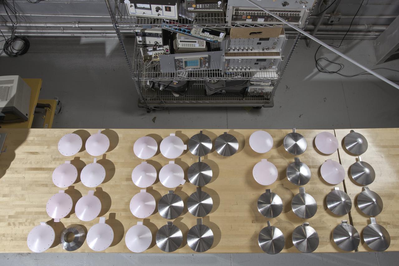
Test 1875 in Unitary Plan Wind Tunnel (UPWT) HIADS TTPM: Trim Tab study on various cone angled heat shields (TTPM) Technology Technical Performance Metric (HIADS) Hypersonic inflatable aerodynamic decelerators
Test 1875 in Unitary Plan Wind Tunnel (UPWT) HIADS TTPM: Trim Tab study on various cone angled heat shields (TTPM) Technology Technical Performance Metric (HIADS) Hypersonic inflatable aerodynamic decelerators
Test 1875 in Unitary Plan Wind Tunnel (UPWT) HIADS TTPM: Trim Tab study on various cone angled heat shields (TTPM) Technology Technical Performance Metric (HIADS) Hypersonic inflatable aerodynamic decelerators
Test 1875 in Unitary Plan Wind Tunnel (UPWT) HIADS TTPM: Trim Tab study on various cone angled heat shields (TTPM) Technology Technical Performance Metric (HIADS) Hypersonic inflatable aerodynamic decelerators
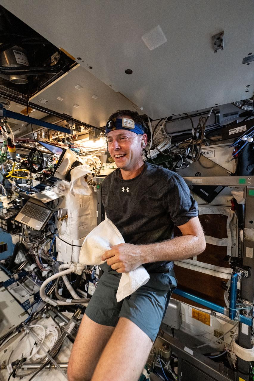
iss072e031342 (10/9/2024) --- NASA astronaut Nick Hague works out wearing T-mini, a headband with a thermosensor that tracks core body temperature. Scientists can use body and environment metrics to study the body’s adaptions to and function in microgravity.
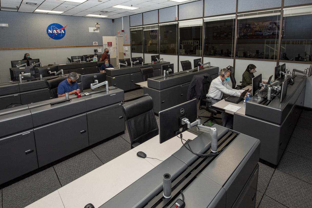
Ames Research Center researchers on the Advanced Air Mobility National Campaign project's Airspace Test Infrastructure (ATI) team monitor surveillance data and metrics from the helicopter in real time during the NC Integrated Dry Run Test team the first week of December 2020 at NASA's Armstrong Flight Research Center in California.
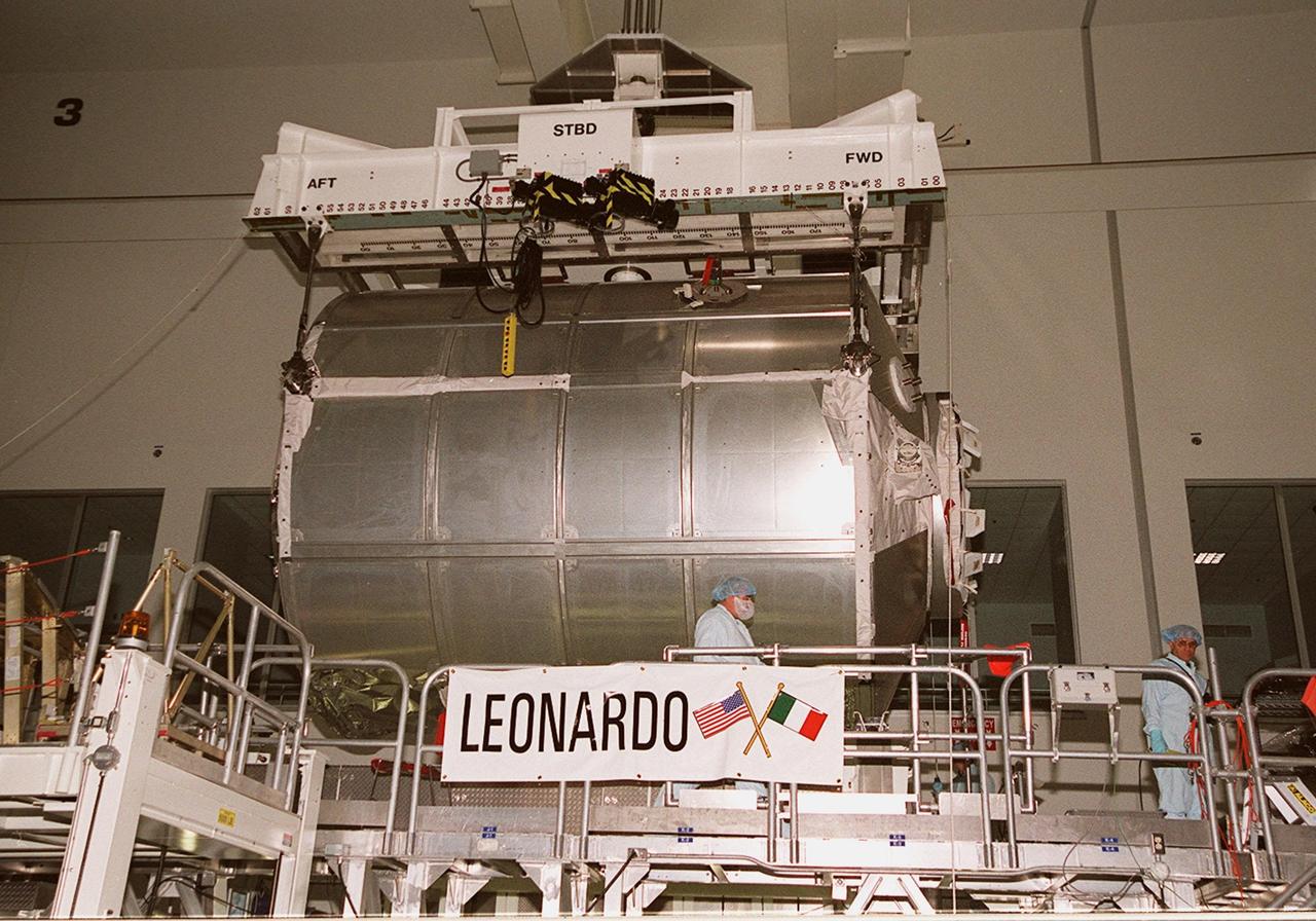
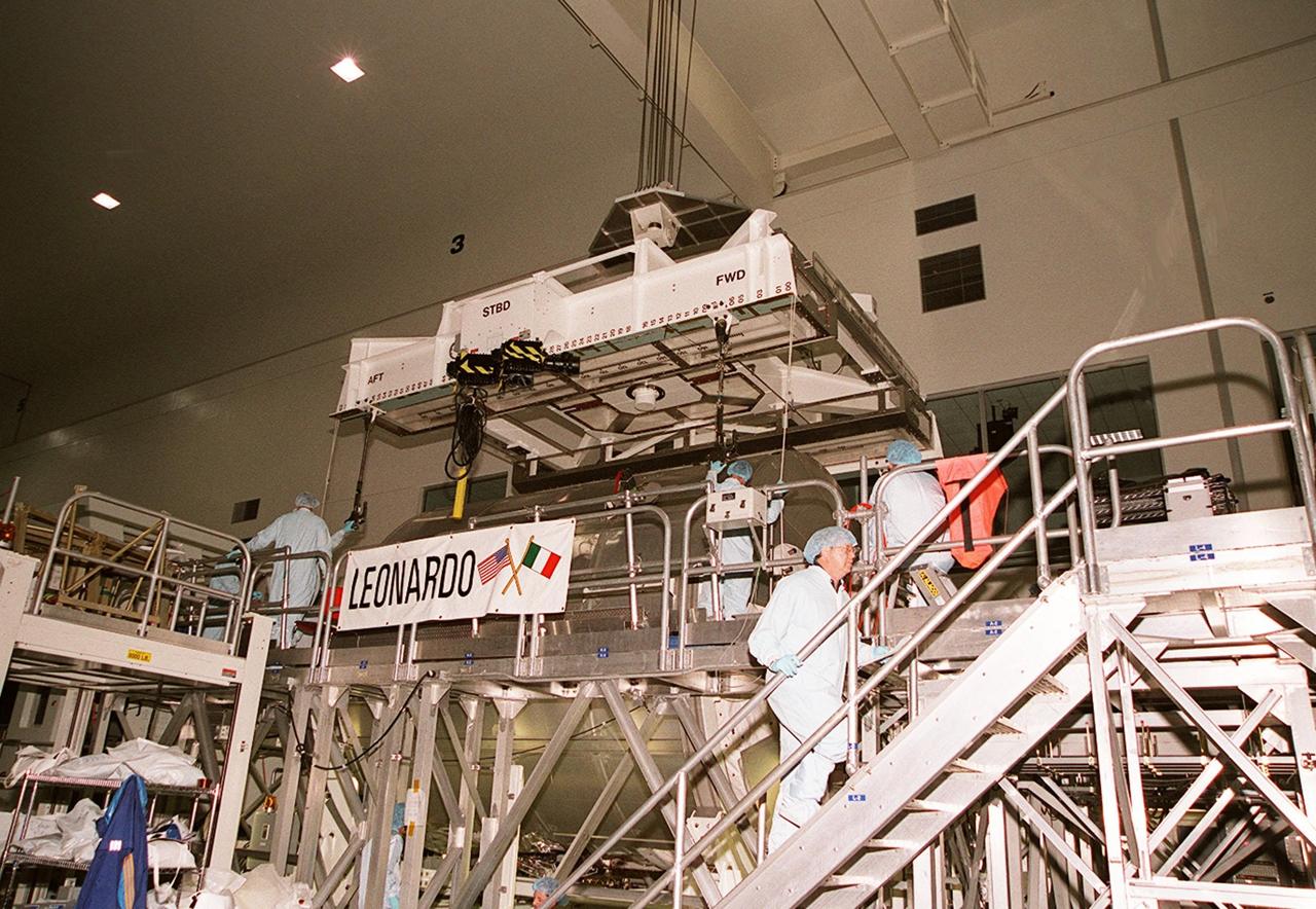
The Multi-Purpose Logistics Module Leonardo is lifted from its stand in the Space Station Processing Facility to move it to the weight and balance scale. The Italian-built MPLM is one of three such pressurized modules that will serve as the International Space Station's "moving vans," carrying laboratory racks filled with equipment, experiments and supplies to and from the station aboard the Space Shuttle. The cylindrical module is approximately 21 feet long and 15 feet in diameter, weighing almost 4.1 metric tons. It can carry up to 9.1 metric tons of cargo packed into 16 standard space station equipment racks. The Leonardo will be launched on mission STS-102 March 8. On that flight, Leonardo will be filled with equipment and supplies to outfit the U.S. laboratory module, to be carried to the ISS on the Feb. 7 launch of STS-98
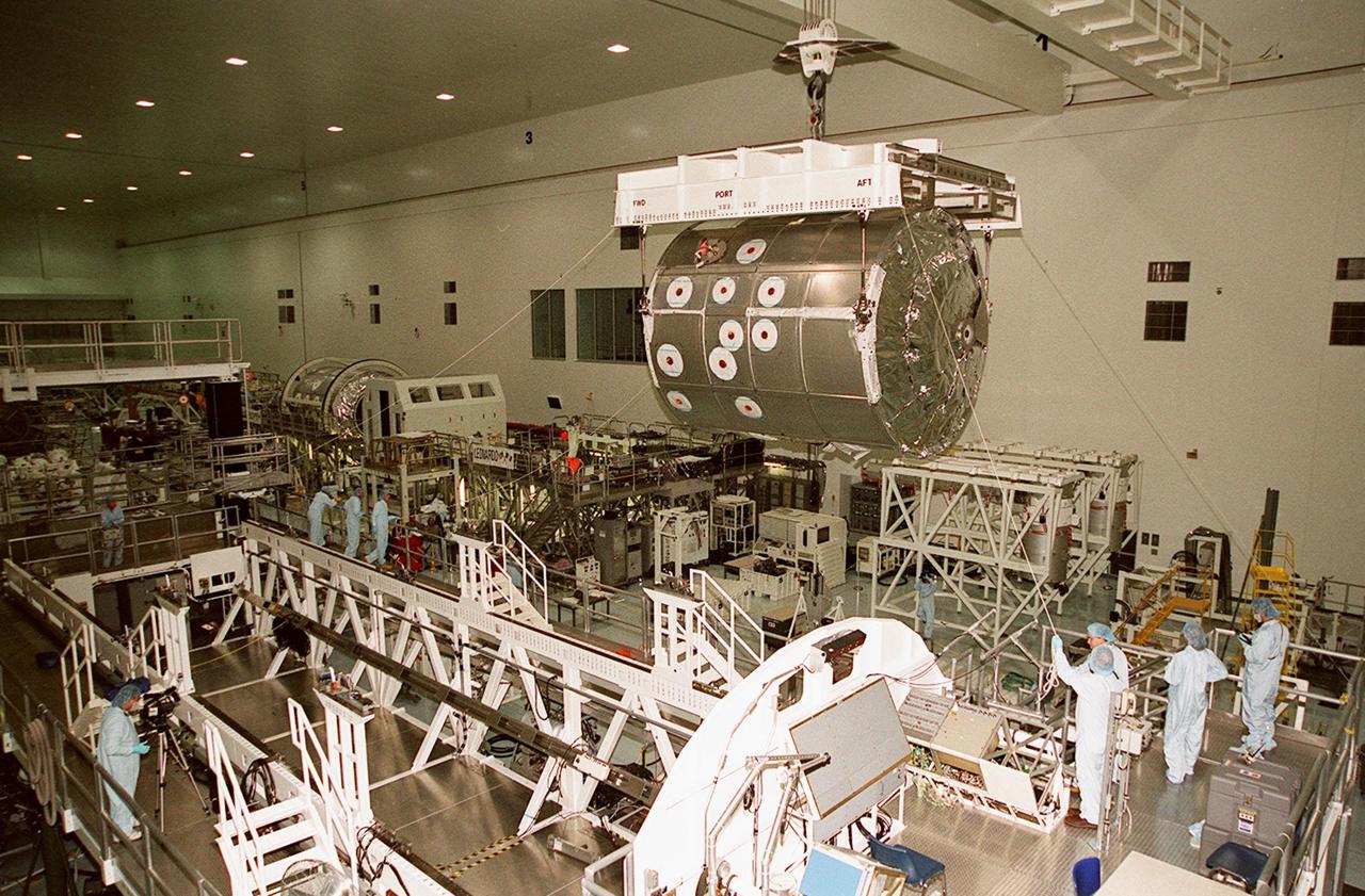
In the Space Station Processing Facility, workers help guide the Multi-Purpose Logistics Module Leonardo as it moves toward the weight and balance scale. The Italian-built MPLM is one of three such pressurized modules that will serve as the International Space Station's "moving vans," carrying laboratory racks filled with equipment, experiments and supplies to and from the station aboard the Space Shuttle. The cylindrical module is approximately 21 feet long and 15 feet in diameter, weighing almost 4.1 metric tons. It can carry up to 9.1 metric tons of cargo packed into 16 standard space station equipment racks. The Leonardo will be launched on mission STS-102 March 8. On that flight, Leonardo will be filled with equipment and supplies to outfit the U.S. laboratory module, to be carried to the ISS on the Feb. 7 launch of STS-98
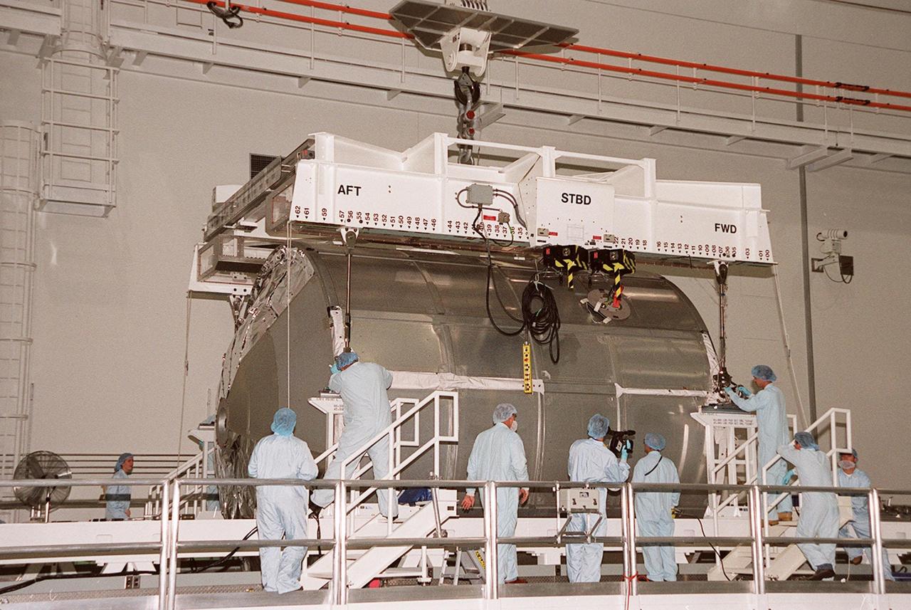
On a workstand in the Space Station Processing Facility, workers stand by while an overhead crane is ready to lift the Multi-Purpose Logistics Module Leonardo to move it to the weight and balance scale. The Italian-built MPLM is one of three such pressurized modules that will serve as the International Space Station's "moving vans," carrying laboratory racks filled with equipment, experiments and supplies to and from the station aboard the Space Shuttle. The cylindrical module is approximately 21 feet long and 15 feet in diameter, weighing almost 4.1 metric tons. It can carry up to 9.1 metric tons of cargo packed into 16 standard space station equipment racks. The Leonardo will be launched on mission STS-102 March 8. On that flight, Leonardo will be filled with equipment and supplies to outfit the U.S. laboratory module, to be carried to the ISS on the Feb. 7 launch of STS-98

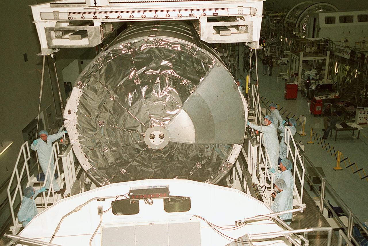
Workers in the Space Station Processing Facility help guide the Multi-Purpose Logistics Module Leonardo as it is lowered toward the weight and balance scale. The Italian-built MPLM is one of three such pressurized modules that will serve as the International Space Station's "moving vans," carrying laboratory racks filled with equipment, experiments and supplies to and from the station aboard the Space Shuttle. The cylindrical module is approximately 21 feet long and 15 feet in diameter, weighing almost 4.1 metric tons. It can carry up to 9.1 metric tons of cargo packed into 16 standard space station equipment racks. The Leonardo will be launched on mission STS-102 March 8. On that flight, Leonardo will be filled with equipment and supplies to outfit the U.S. laboratory module, to be carried to the ISS on the Feb. 7 launch of STS-98
In the Space Station Processing Facility, the Multi-Purpose Logistics Module Leonardo finally rests on the weight and balance scale. The Italian-built MPLM is one of three such pressurized modules that will serve as the International Space Station's "moving vans," carrying laboratory racks filled with equipment, experiments and supplies to and from the station aboard the Space Shuttle. The cylindrical module is approximately 21 feet long and 15 feet in diameter, weighing almost 4.1 metric tons. It can carry up to 9.1 metric tons of cargo packed into 16 standard space station equipment racks. The Leonardo will be launched on mission STS-102 March 8. On that flight, Leonardo will be filled with equipment and supplies to outfit the U.S. laboratory module, to be carried to the ISS on the Feb. 7 launch of STS-98
Workers in the Space Station Processing Facility steady the Multi-Purpose Logistics Module Leonardo as it is lowered toward the weight and balance scale. The Italian-built MPLM is one of three such pressurized modules that will serve as the International Space Station's "moving vans," carrying laboratory racks filled with equipment, experiments and supplies to and from the station aboard the Space Shuttle. The cylindrical module is approximately 21 feet long and 15 feet in diameter, weighing almost 4.1 metric tons. It can carry up to 9.1 metric tons of cargo packed into 16 standard space station equipment racks. The Leonardo will be launched on mission STS-102 March 8. On that flight, Leonardo will be filled with equipment and supplies to outfit the U.S. laboratory module, to be carried to the ISS on the Feb. 7 launch of STS-98

Satellite images from 2022 (Main image) and 1999 (Figure A) capture the retreat of Zachariae Isstrom, a glacier in northeast Greenland, as icebergs broke off its edge over the course of 23 years. In a recent study in Nature, researchers from NASA's Jet Propulsion Laboratory in Southern California calculated that Zachariae lost an estimated 176 billion tons (160 billion metric tons) of ice in the period between 1985 and 2022. That was the greatest mass lost for the period of any of the 207 glaciers analyzed in the paper. The earlier image was taken by the Enhanced Thematic Mapper Plus on the Landsat 7 satellite on Aug. 5, 1999, while the later image was captured by the Operational Land Imager on the Landsat 8 satellite on Aug. 22, 2022. The study took a comprehensive look at glacial retreat around the edges of the entire Greenland Ice Sheet from 1985 to 2022 and found that 179 glaciers retreated significantly since 1985, 27 held steady, and just one advanced slightly. The study found that overall the ice sheet shed about 1,140 billion tons (1,034 billion metric tons) of ice from 1985 to 2022, one-fifth more mass than previously estimated, as icebergs fell into the ocean at an accelerating rate. Most of the ice loss came from below sea level, in fjords on Greenland's periphery. Once occupied by ancient glacial ice, many of these deep coastal valleys have filled with seawater – meaning the ice that broke off made little net contribution to sea level. But the loss likely accelerated the movement of ice flowing down from higher elevations, which in turn added to sea level rise. It also added previously unaccounted-for fresh water to the North Atlantic Ocean, which could have impacts on global ocean currents. https://photojournal.jpl.nasa.gov/catalog/PIA26118

Satellite images from 2022 (Main image) and 1985 (Figure A) capture the retreat of Jakobshavn Isbrae, a glacier on Greenland's western coast, as icebergs broke off its edge over nearly four decades. In a recent study in Nature, researchers from NASA's Jet Propulsion Laboratory in Southern California calculated that Jakobshavn lost an estimated 97 billion tons (88 billion metric tons) of ice in the period between the two images. The earlier image was taken by the Thematic Mapper instrument on the Landsat 5 satellite on Sept. 5, 1985, while the later image was captured by the Operational Land Imager on the Landsat 8 satellite on Sept. 4, 2022. Of the 207 glaciers analyzed in the study, Jakobshavn lost the second most ice mass, trailing only Zachariae Isstrom, a glacier in northeast Greenland. The study took a comprehensive look at glacial retreat around the edges of the entire Greenland Ice Sheet from 1985 to 2022 and found that 179 glaciers retreated significantly since 1985, 27 held steady, and just one advanced slightly. The study found that overall the ice sheet shed about 1,140 billion tons (1,034 billion metric tons) of ice from 1985 to 2022, one-fifth more mass than previously estimated, as icebergs fell into the ocean at an accelerating rate. Most of the ice loss came from below sea level, in fjords on Greenland's periphery. Once occupied by ancient glacial ice, many of these deep coastal valleys have filled with seawater – meaning the ice that broke off made little net contribution to sea level. But the loss likely accelerated the movement of ice flowing down from higher elevations, which in turn added to sea level rise. It also added previously unaccounted-for fresh water to the North Atlantic Ocean, which could have impacts on global ocean currents. https://photojournal.jpl.nasa.gov/catalog/PIA26117
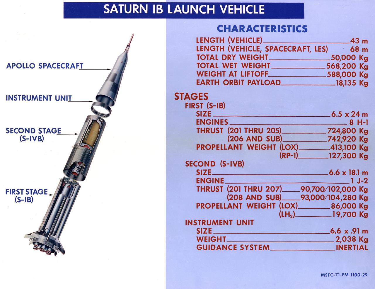
This 1968 cutaway drawing illustrates the Saturn IB launch vehicle with its two booster stages, the S-IB (first stage) and S-IVB (second stage), and provides the vital statistics in metric units. Developed by the Marshall Space Flight Center (MSFC) as an interim vehicle in MSFC's "building block" approach to the Saturn rocket development, the Saturn IB utilized Saturn I technology to further develop and refine the larger boosters and the Apollo spacecraft capabilities required for the marned lunar missions.
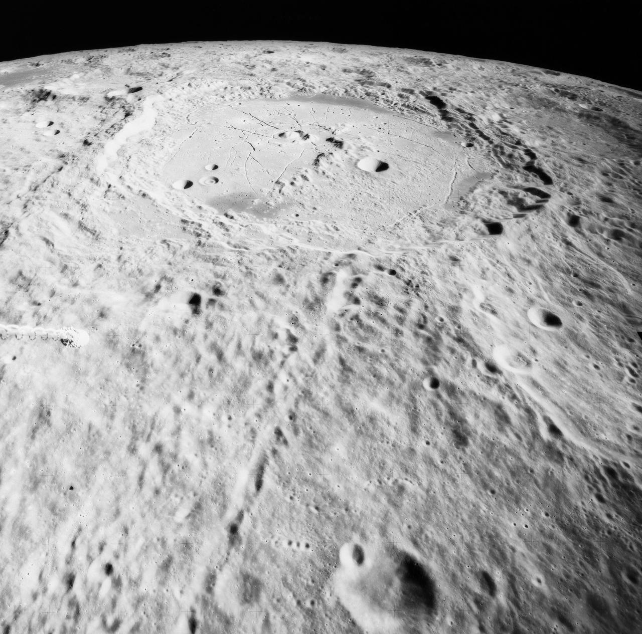
S71-44668 (31 July-2 Aug. 1971) --- An oblique view of the crater Humboldt, as photographed by the Fairchild metric camera in the Scientific Instrument Module (SIM) bay of the Apollo 15 Command and Service Modules (CSM) in lunar orbit. This view is looking southerly. Humboldt, which is 200 kilometers (124 statute miles) in diameter, is located at 81 degrees east longitude and 27 degrees south latitude. The three-inch mapping camera was one of eight lunar orbital science experiments located in the SIM bay.
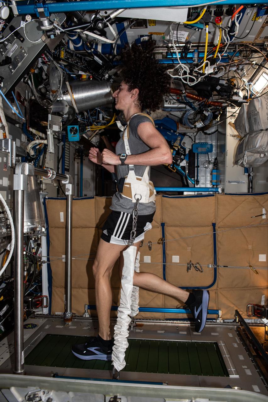
iss070e100775 (2/25/2024) --- NASA astronaut Jasmin Moghbeli runs on the T2 treadmill system on space station. Daily exercise is an important component of staying healthy in space. Without Earth’s gravity, bone and muscle atrophy or become smaller and weaker. On her left wrist, Moghbeli wears Actiwatch, a monitor that measures body metrics like sleep and heart rate.
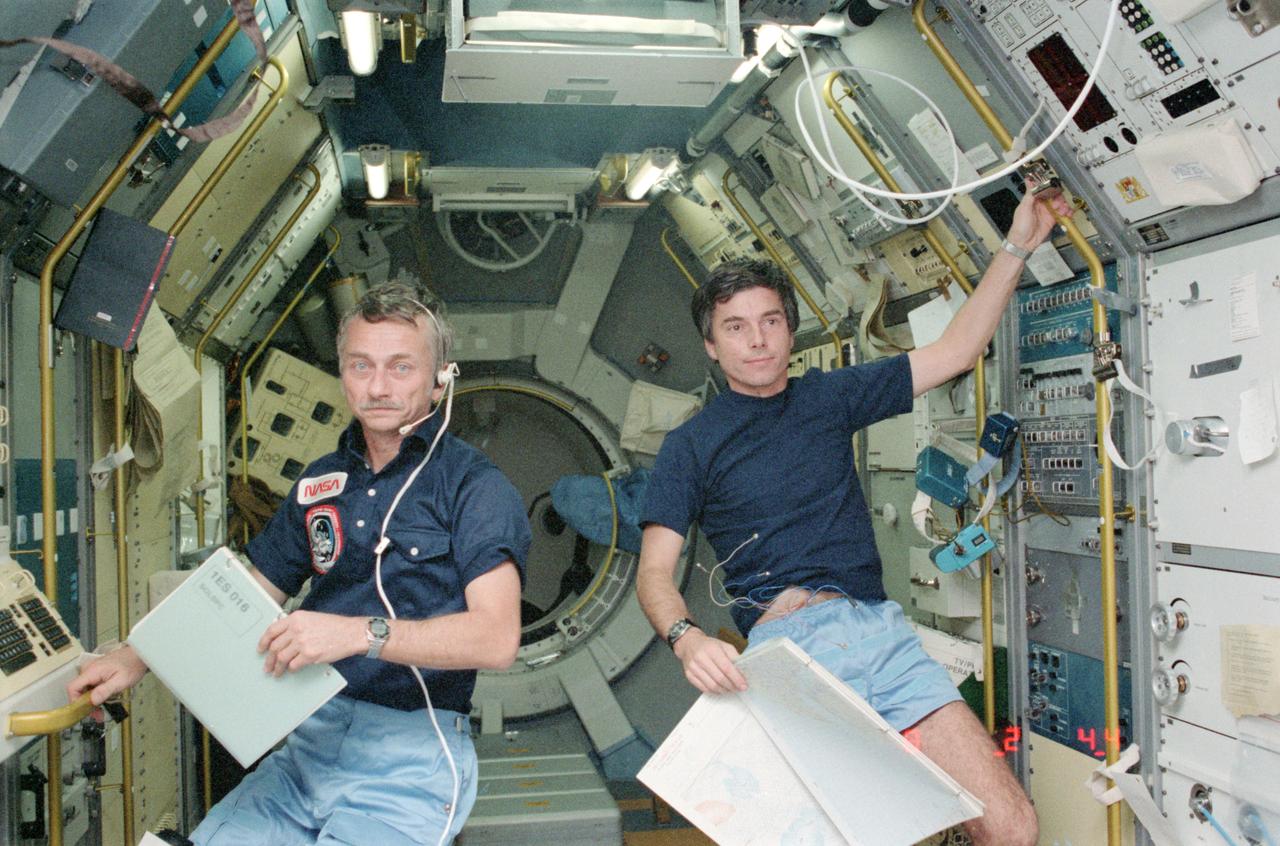
STS009-123-340 (28 Nov 1983) --- Astronaut Owen K. Garriott, STS-9 mission specialist, left, and Ulf Merbold, payload specialist, take a break from monitoring experimentation aboard Spacelab to be photographed. Dr. Garriott, holds in his left hand a data/log book for the solar spectrum experiment. Dr. Merbold, holds a map in his left hand for the monitoring of ground objectives of the metric camera.
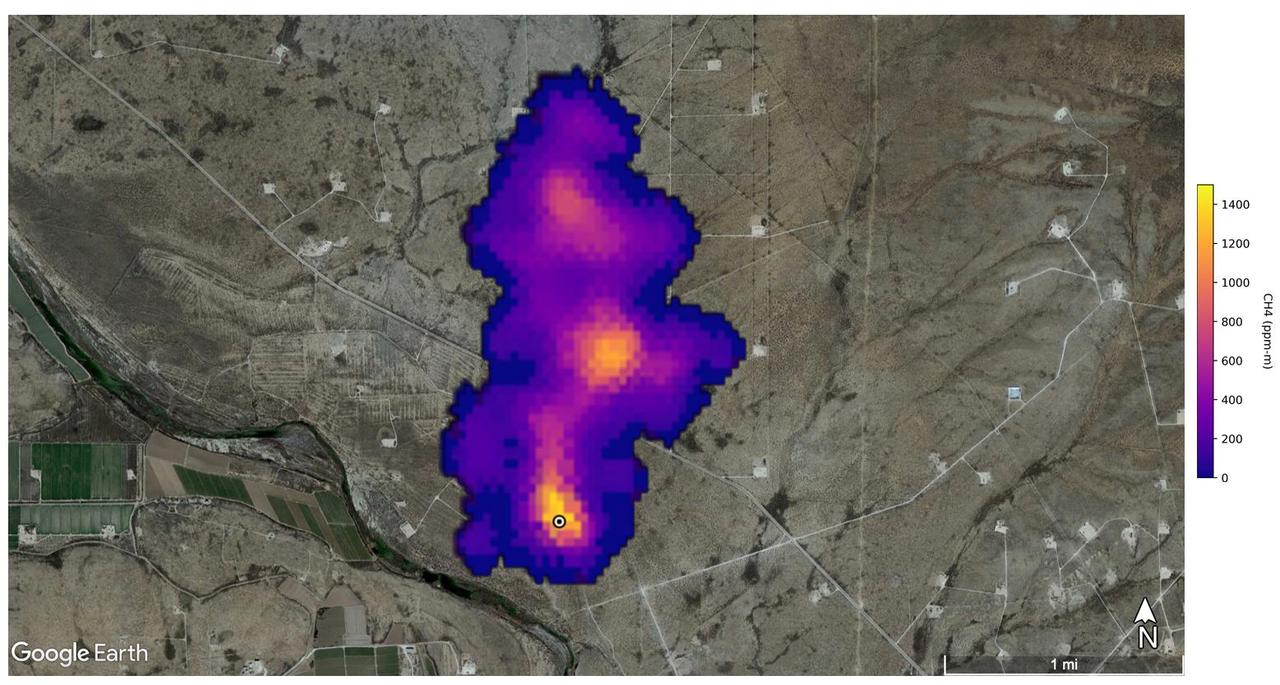
A plume of methane – a potent greenhouse gas about 80 times more effective at trapping heat in the atmosphere than carbon dioxide – is detected flowing from an area southeast of Carlsbad, New Mexico, in an image that uses data from NASA's Earth Surface Mineral Dust Source Investigation (EMIT) mission. The 2-mile (3.3-kilometer) long plume originates in an area known as the Permian Basin, which spans parts of southeastern New Mexico and western Texas and is one of the largest oilfields in the world. EMIT uses an imaging spectrometer to detect the unique pattern of reflected and absorbed light – called a spectral fingerprint – from various materials on Earth's surface and in its atmosphere. Perched on the International Space Station, EMIT was originally intended to map the prevalence of minerals in Earth's arid regions, such as the deserts of Africa and Australia. Scientists verified that EMIT could also detect methane and carbon dioxide when they were checking the accuracy of the image spectrometer's mineral data. The data for these images was collected by EMIT in August 2022. Scientists estimate flow rates of 20.2 tons (18.3 metric tons) per hour at the Permian site, 55.6 tons (50.4 metric tons) per hour in total for the Turkmenistan sources, and 9.4 tons (8.5 metric tons) per hour at the Iran site. While quite large, these emission rates are broadly consistent with previous studies of locations like the Permian Basin, as well as emission source types like landfills. The Turkmenistan example has a similar magnitude to the 2015 Aliso Canyon Blowout. https://photojournal.jpl.nasa.gov/catalog/PIA25592
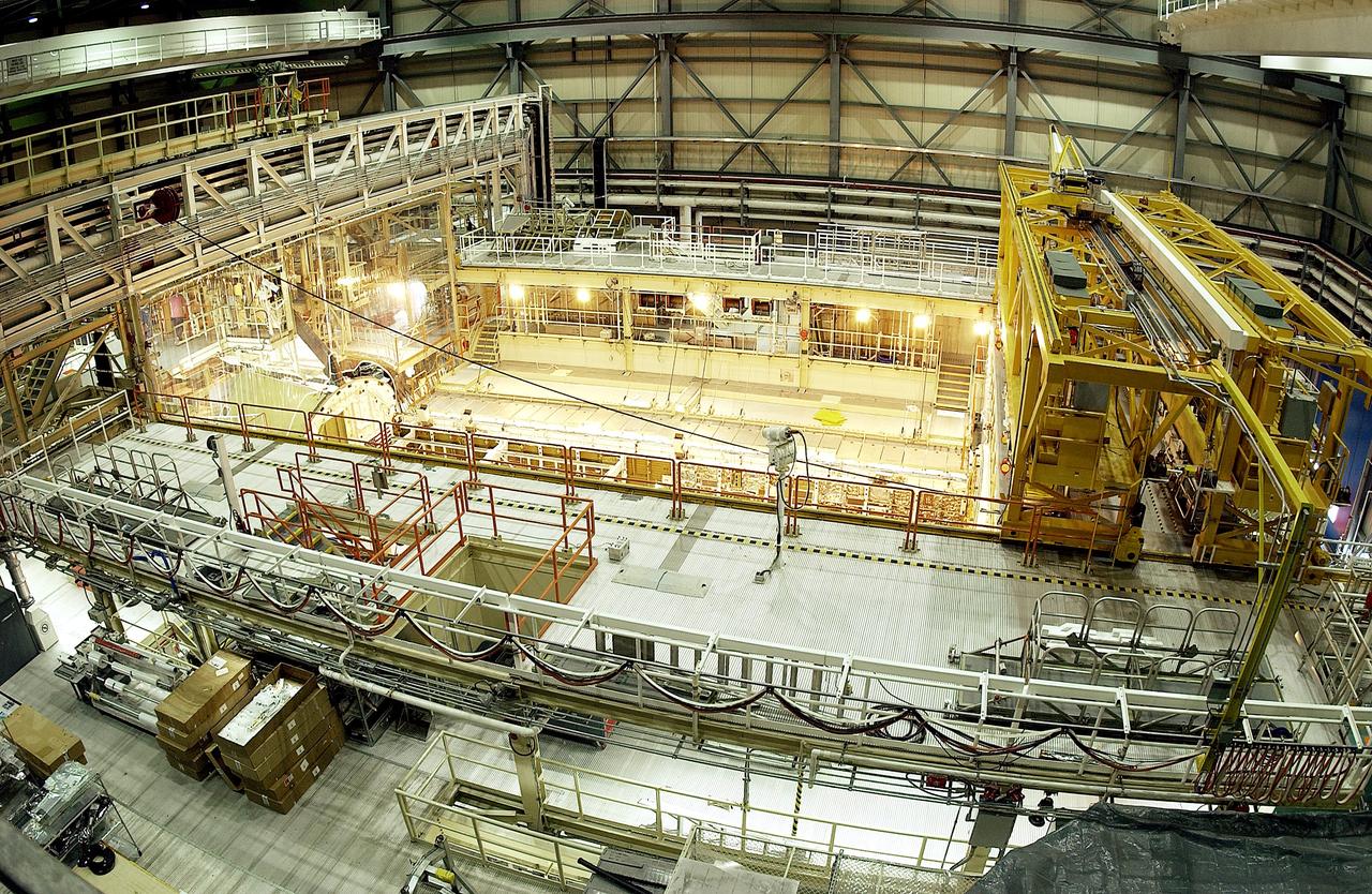
KENNEDY SPACE CENTER, FLA. - This bird's-eye view of a high bay in the Orbiter Processing Facility (OPF) shows the open payload bay of Space Shuttle Discovery surrounded by the standard platforms and equipment required to process a Space Shuttle orbiter. The high bay is 197 feet (60 meters) long, 150 feet (46 meters) wide, 95 feet (29 meters) high, and encompasses a 29,000-square-foot (2,694-meter) area. The 30-ton (27-metric-ton) bridge crane (yellow device, right) has a hook height of approximately 66 feet (20 meters). Platforms, a main access bridge, and two rolling bridges with trucks provide access to various parts of the orbiter. In addition to routine servicing and checkout, the inspections and modifications made to enhance Discovery's performance and upgrade its systems were performed in the OPF during its recently completed Orbiter Major Modification (OMM) period.
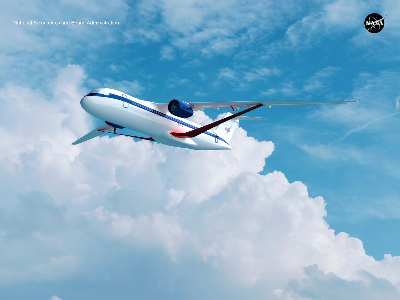
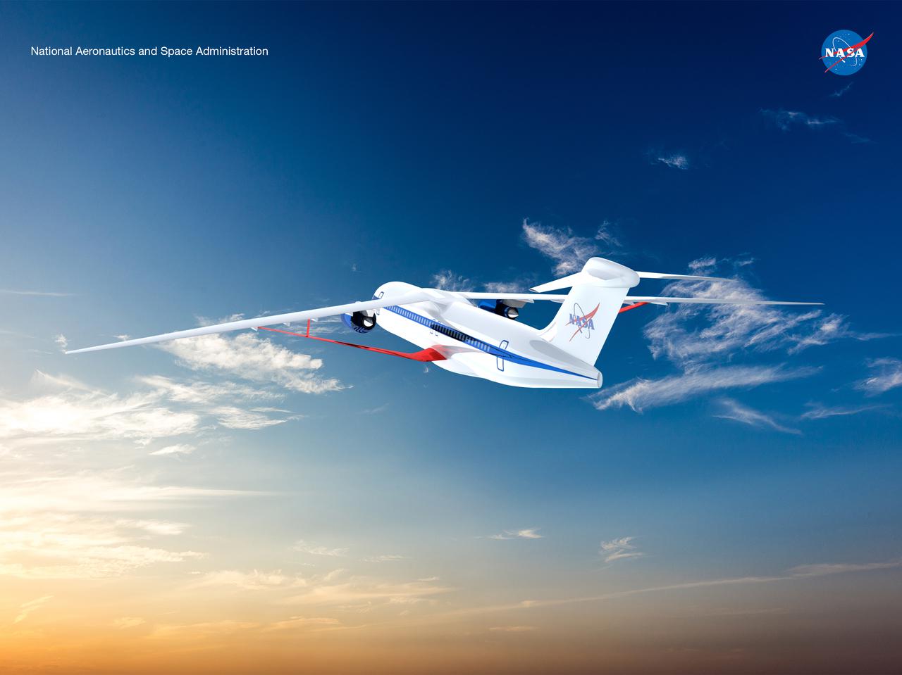
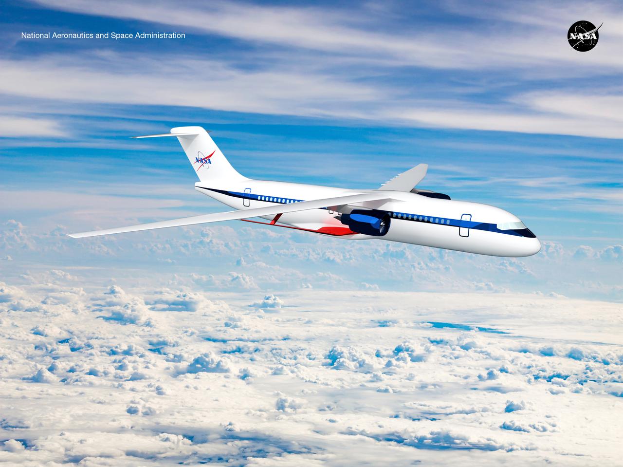
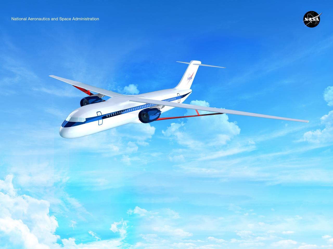
Notice anything different about the wings on this airliner? This conceptual truss-braced wing narrowbody is an aircraft with a 170ft span folding wing. By utilizing trusses, the aircraft can have longer, thinner wings with greater aspect ratios. This, in turn, translates into less drag and 5-10% less fuel burned. The Transonic Truss-Braced Wing aircraft originated from a joint effort by NASA and Boeing to develop subsonic commercial transport concepts – meeting NASA-defined metrics in terms of reduced noise, emissions, and fuel consumption. The design is currently undergoing wind tunnel testing and other studies by NASA researchers.
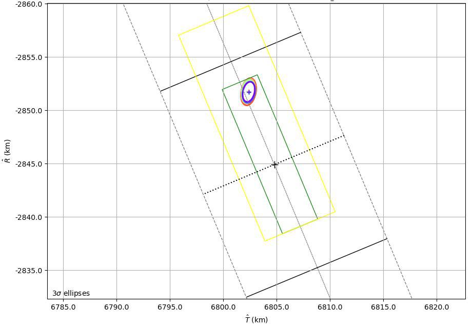
This graphic shows the B-Plane for NASA's Mars 2020 Perseverance rover mission as of February 15, 2021. A B-Plane is a key performance metric that navigators for interplanetary missions use to determine the accuracy of their spacecraft's trajectory. The entry target on the lower right of the image (black cross) depicts the point where mission navigators are targeting the Mars 2020 spacecraft to enter the Red Planet's atmosphere. Higher up, the red, orange, green, and blue ovals depict the estimated "entry uncertainty ellipse" for the spacecraft as determined by previous navigation solutions. The inner-most ring (purple) depicts the most recent trajectory path. https://photojournal.jpl.nasa.gov/catalog/PIA24296
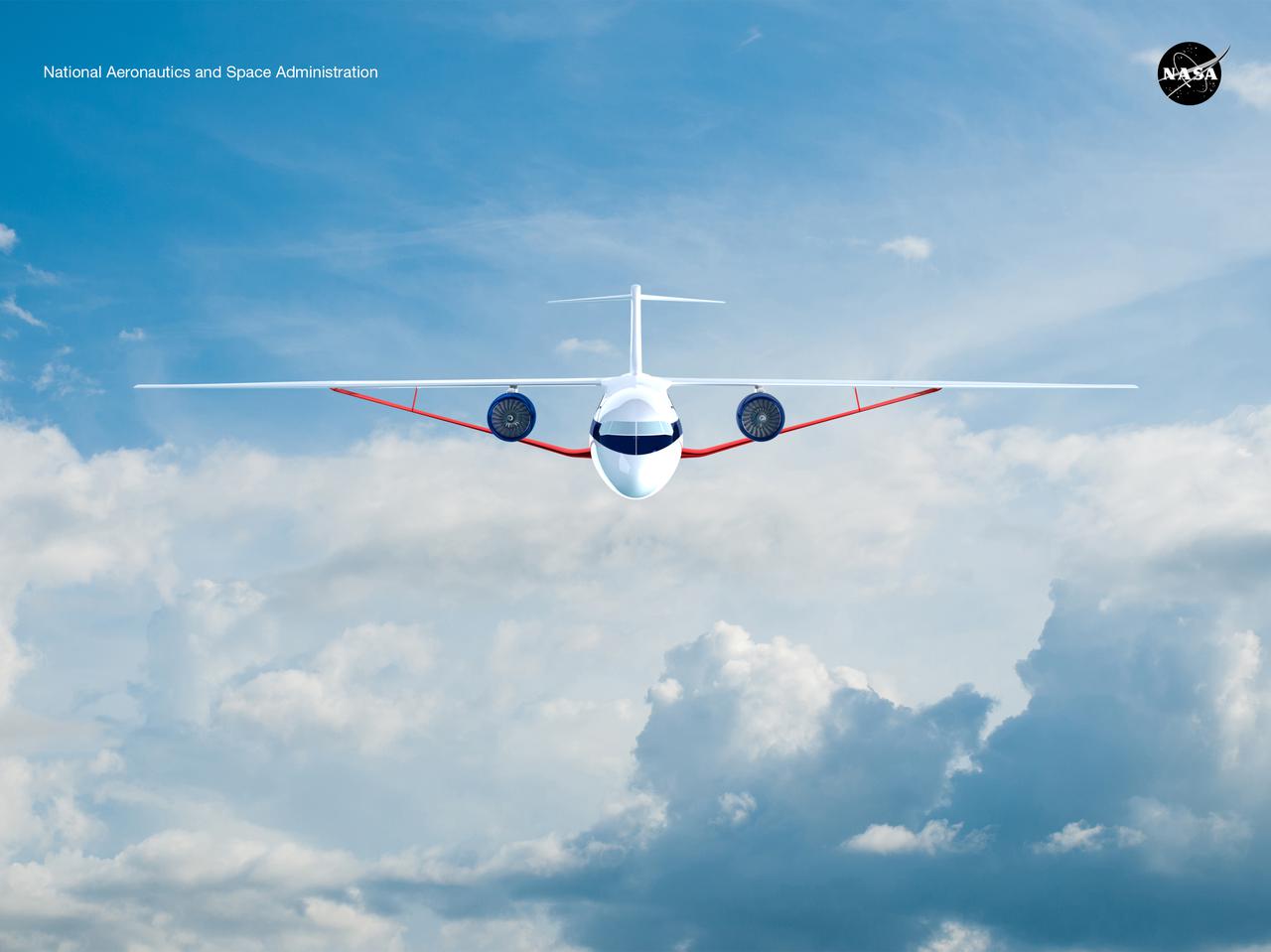
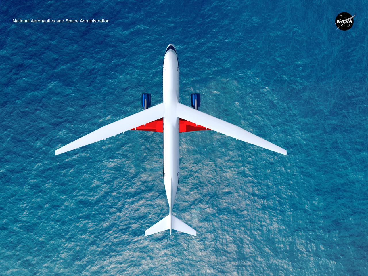
Notice anything different about the wings on this airliner? This conceptual truss-braced wing narrowbody is an aircraft with a 170ft span folding wing. By utilizing trusses, the aircraft can have longer, thinner wings with greater aspect ratios. This, in turn, translates into less drag and 5-10% less fuel burned. The Transonic Truss-Braced Wing aircraft originated from a joint effort by NASA and Boeing to develop subsonic commercial transport concepts – meeting NASA-defined metrics in terms of reduced noise, emissions, and fuel consumption. The design is currently undergoing wind tunnel testing and other studies by NASA researchers.
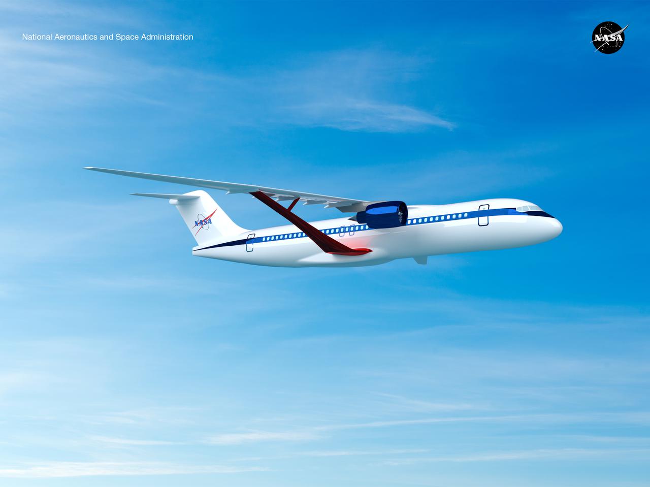
Notice anything different about the wings on this airliner? This conceptual truss-braced wing narrowbody is an aircraft with a 170ft span folding wing. By utilizing trusses, the aircraft can have longer, thinner wings with greater aspect ratios. This, in turn, translates into less drag and 5-10% less fuel burned. The Transonic Truss-Braced Wing aircraft originated from a joint effort by NASA and Boeing to develop subsonic commercial transport concepts – meeting NASA-defined metrics in terms of reduced noise, emissions, and fuel consumption. The design is currently undergoing wind tunnel testing and other studies by NASA researchers.
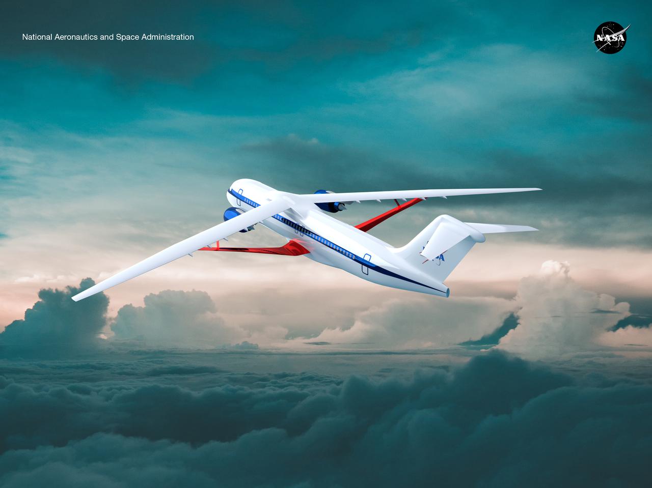
Notice anything different about the wings on this airliner? This conceptual truss-braced wing narrowbody is an aircraft with a 170ft span folding wing. By utilizing trusses, the aircraft can have longer, thinner wings with greater aspect ratios. This, in turn, translates into less drag and 5-10% less fuel burned. The Transonic Truss-Braced Wing aircraft originated from a joint effort by NASA and Boeing to develop subsonic commercial transport concepts – meeting NASA-defined metrics in terms of reduced noise, emissions, and fuel consumption. The design is currently undergoing wind tunnel testing and other studies by NASA researchers.
Notice anything different about the wings on this airliner? This conceptual truss-braced wing narrowbody is an aircraft with a 170ft span folding wing. By utilizing trusses, the aircraft can have longer, thinner wings with greater aspect ratios. This, in turn, translates into less drag and 5-10% less fuel burned. The Transonic Truss-Braced Wing aircraft originated from a joint effort by NASA and Boeing to develop subsonic commercial transport concepts – meeting NASA-defined metrics in terms of reduced noise, emissions, and fuel consumption. The design is currently undergoing wind tunnel testing and other studies by NASA researchers.
Notice anything different about the wings on this airliner? This conceptual truss-braced wing narrowbody is an aircraft with a 170ft span folding wing. By utilizing trusses, the aircraft can have longer, thinner wings with greater aspect ratios. This, in turn, translates into less drag and 5-10% less fuel burned. The Transonic Truss-Braced Wing aircraft originated from a joint effort by NASA and Boeing to develop subsonic commercial transport concepts – meeting NASA-defined metrics in terms of reduced noise, emissions, and fuel consumption. The design is currently undergoing wind tunnel testing and other studies by NASA researchers.
Notice anything different about the wings on this airliner? This conceptual truss-braced wing narrowbody is an aircraft with a 170ft span folding wing. By utilizing trusses, the aircraft can have longer, thinner wings with greater aspect ratios. This, in turn, translates into less drag and 5-10% less fuel burned. The Transonic Truss-Braced Wing aircraft originated from a joint effort by NASA and Boeing to develop subsonic commercial transport concepts – meeting NASA-defined metrics in terms of reduced noise, emissions, and fuel consumption. The design is currently undergoing wind tunnel testing and other studies by NASA researchers.
Notice anything different about the wings on this airliner? This conceptual truss-braced wing narrowbody is an aircraft with a 170ft span folding wing. By utilizing trusses, the aircraft can have longer, thinner wings with greater aspect ratios. This, in turn, translates into less drag and 5-10% less fuel burned. The Transonic Truss-Braced Wing aircraft originated from a joint effort by NASA and Boeing to develop subsonic commercial transport concepts – meeting NASA-defined metrics in terms of reduced noise, emissions, and fuel consumption. The design is currently undergoing wind tunnel testing and other studies by NASA researchers.
Notice anything different about the wings on this airliner? This conceptual truss-braced wing narrowbody is an aircraft with a 170ft span folding wing. By utilizing trusses, the aircraft can have longer, thinner wings with greater aspect ratios. This, in turn, translates into less drag and 5-10% less fuel burned. The Transonic Truss-Braced Wing aircraft originated from a joint effort by NASA and Boeing to develop subsonic commercial transport concepts – meeting NASA-defined metrics in terms of reduced noise, emissions, and fuel consumption. The design is currently undergoing wind tunnel testing and other studies by NASA researchers.
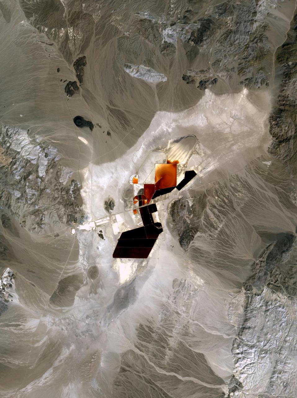
In Clayton Valley, Nevada, lithium has been produced since 1966. Currently it is produced by pumping lithium-rich brine to the surface to evaporate, or processed through direct lithium extraction. About 5,000 metric tons of lithium carbonate are produced annually at Nevada's only lithium-producing site. In the future, newly discovered deposits will produce more lithium than any other state. The image was acquired April 23, 2023, covers an area of 21.5 by 28.8 km, and is located at 37.75 degrees north, 117.6 degrees west. https://photojournal.jpl.nasa.gov/catalog/PIA26505
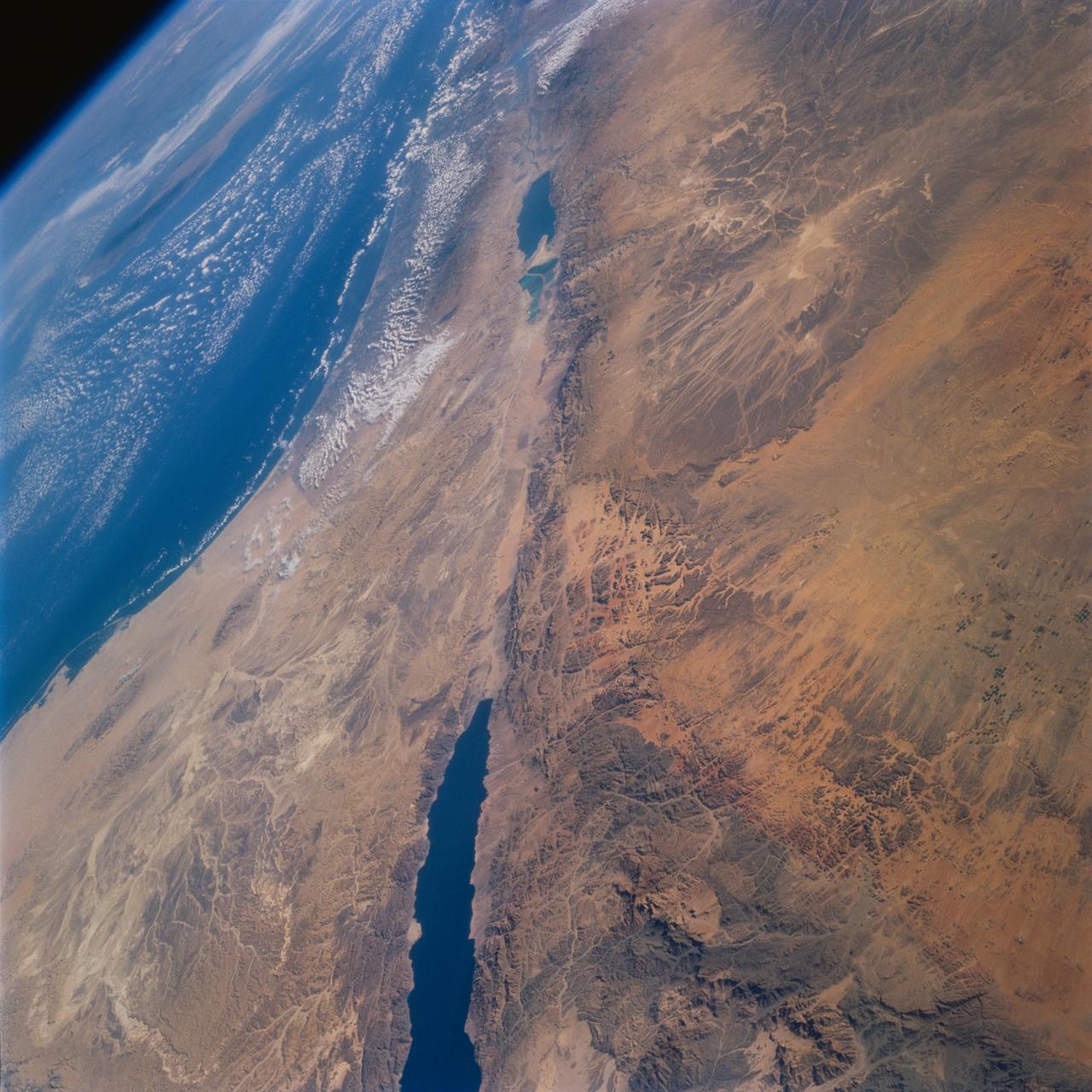
STS077-732-093 (19-29 May 1996) --- This high oblique perspective from the Space Shuttle Endeavour shows the Dead Sea Rift Valley and the surrounding deserts. North is to the right side of the frame. The vegetation line on the coast between Egypt and Israel is clearly visible. Crete is visible in the Mediterranean Sea. The Dead Sea was formed approximately 3 million years ago. A passage opened up to the sea and the water poured in. It is about 1,300 feet below sea level. It is fed by the Jordan River and numerous mineral springs from the surrounding hills. It is estimated to contain 43 million metric tons of salt. The salinity is 32 percent.
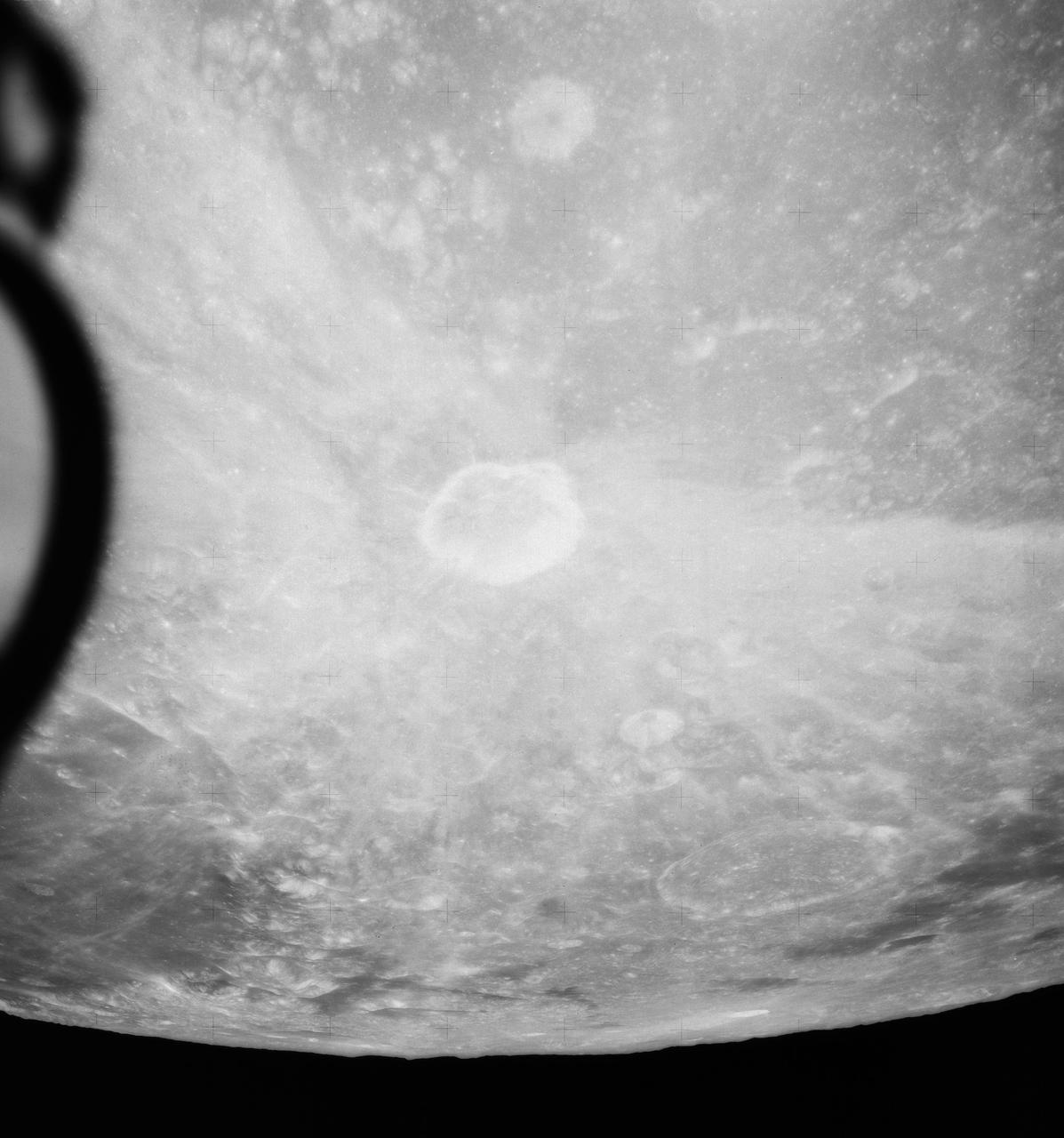
S71-44669 (31 July-2 Aug. 1971) --- An oblique view of the rayed crater Proclus on the lunar nearside, as photographed by the Fairchild metric camera in the SIM bay of the Apollo 15 Command and Service Modules (CSM) in lunar orbit. This view is looking north. The Sea of Crisis is at upper right. Proclus, which is 28 kilometers (16.58 statute miles) in diameter, is located at 47 degrees east longitude and 16 degrees north latitude. The Marsh of Sleep is at lower left. A small portion of the Sea of Tranquility can be seen at upper left. The crater Macrobius is located at upper left. The three-inch mapping camera was one of eight lunar orbital science experiments mounted in the SIM bay.
Notice anything different about the wings on this airliner? This conceptual truss-braced wing narrowbody is an aircraft with a 170ft span folding wing. By utilizing trusses, the aircraft can have longer, thinner wings with greater aspect ratios. This, in turn, translates into less drag and 5-10% less fuel burned. The Transonic Truss-Braced Wing aircraft originated from a joint effort by NASA and Boeing to develop subsonic commercial transport concepts – meeting NASA-defined metrics in terms of reduced noise, emissions, and fuel consumption. The design is currently undergoing wind tunnel testing and other studies by NASA researchers.
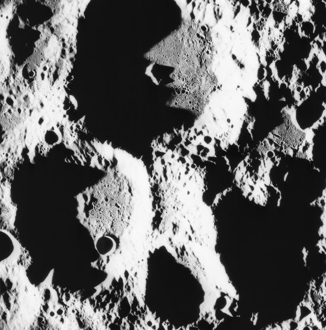
S71-44672 (30 July 1971) --- A near vertical view of the crater Paracelsus (formerly called I.A.U. Crater 365) on the lunar farside, as photographed by the Fairchild metric camera in the Scientific Instrumentation Module (SIM) bay of the Apollo 15 Command and Service Modules (CSM) in lunar orbit. Note mountain peak in center of Paracelsus. The coordinates of the center of Paracelsus are 163 degrees east longitude and 23 degrees south latitude. The second largest crater in the picture is identified as number 364 by the I.A.U. North will be at the top of the picture if held with Paracelsus at top center. The three-inch mapping camera was one of eight lunar orbital science experiments mounted in the SIM bay.
Notice anything different about the wings on this airliner? This conceptual truss-braced wing narrowbody is an aircraft with a 170ft span folding wing. By utilizing trusses, the aircraft can have longer, thinner wings with greater aspect ratios. This, in turn, translates into less drag and 5-10% less fuel burned. The Transonic Truss-Braced Wing aircraft originated from a joint effort by NASA and Boeing to develop subsonic commercial transport concepts – meeting NASA-defined metrics in terms of reduced noise, emissions, and fuel consumption. The design is currently undergoing wind tunnel testing and other studies by NASA researchers.
Notice anything different about the wings on this airliner? This conceptual truss-braced wing narrowbody is an aircraft with a 170ft span folding wing. By utilizing trusses, the aircraft can have longer, thinner wings with greater aspect ratios. This, in turn, translates into less drag and 5-10% less fuel burned. The Transonic Truss-Braced Wing aircraft originated from a joint effort by NASA and Boeing to develop subsonic commercial transport concepts – meeting NASA-defined metrics in terms of reduced noise, emissions, and fuel consumption. The design is currently undergoing wind tunnel testing and other studies by NASA researchers.
Notice anything different about the wings on this airliner? This conceptual truss-braced wing narrowbody is an aircraft with a 170ft span folding wing. By utilizing trusses, the aircraft can have longer, thinner wings with greater aspect ratios. This, in turn, translates into less drag and 5-10% less fuel burned. The Transonic Truss-Braced Wing aircraft originated from a joint effort by NASA and Boeing to develop subsonic commercial transport concepts – meeting NASA-defined metrics in terms of reduced noise, emissions, and fuel consumption. The design is currently undergoing wind tunnel testing and other studies by NASA researchers.
Notice anything different about the wings on this airliner? This conceptual truss-braced wing narrowbody is an aircraft with a 170ft span folding wing. By utilizing trusses, the aircraft can have longer, thinner wings with greater aspect ratios. This, in turn, translates into less drag and 5-10% less fuel burned. The Transonic Truss-Braced Wing aircraft originated from a joint effort by NASA and Boeing to develop subsonic commercial transport concepts – meeting NASA-defined metrics in terms of reduced noise, emissions, and fuel consumption. The design is currently undergoing wind tunnel testing and other studies by NASA researchers.
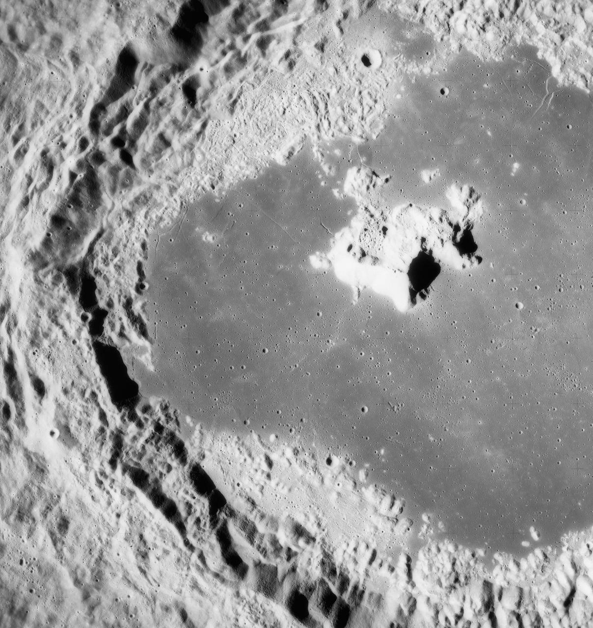
S71-44670 (31 July 1971) --- A near vertical view of the crater Tsiolkovsky on the lunar farside, as photographed by the Fairchild metric camera in the Scientific Instrument Module (SIM) bay of the Apollo 15 Command and Service Modules (CSM) in lunar orbit. This view is looking northerly. The coordinates of the crater's central peaks are 128 degrees east longitude and 20 degrees south latitude. The mare area measured from east to west is approximately 145 kilometers (90 statute miles) across. The three-inch mapping camera was one of eight lunar orbital science experiments mounted in the SIM bay.
Notice anything different about the wings on this airliner? This conceptual truss-braced wing narrowbody is an aircraft with a 170ft span folding wing. By utilizing trusses, the aircraft can have longer, thinner wings with greater aspect ratios. This, in turn, translates into less drag and 5-10% less fuel burned. The Transonic Truss-Braced Wing aircraft originated from a joint effort by NASA and Boeing to develop subsonic commercial transport concepts – meeting NASA-defined metrics in terms of reduced noise, emissions, and fuel consumption. The design is currently undergoing wind tunnel testing and other studies by NASA researchers.
Notice anything different about the wings on this airliner? This conceptual truss-braced wing narrowbody is an aircraft with a 170ft span folding wing. By utilizing trusses, the aircraft can have longer, thinner wings with greater aspect ratios. This, in turn, translates into less drag and 5-10% less fuel burned. The Transonic Truss-Braced Wing aircraft originated from a joint effort by NASA and Boeing to develop subsonic commercial transport concepts – meeting NASA-defined metrics in terms of reduced noise, emissions, and fuel consumption. The design is currently undergoing wind tunnel testing and other studies by NASA researchers.
This video still depicts the recently deployed starboard and port solar arrays towering over the International Space Station (ISS). The video was recorded on STS-97's 65th orbit. Delivery, assembly, and activation of the solar arrays was the main mission objective of STS-97. The electrical power system, which is built into a 73-meter (240-foot) long solar array structure consists of solar arrays, radiators, batteries, and electronics, and will provide the power necessary for the first ISS crews to live and work in the U.S. segment. The entire 15.4-metric ton (17-ton) package is called the P6 Integrated Truss Segment, and is the heaviest and largest element yet delivered to the station aboard a space shuttle. The STS-97 crew of five launched aboard the Space Shuttle Orbiter Endeavor on November 30, 2000 for an 11 day mission.
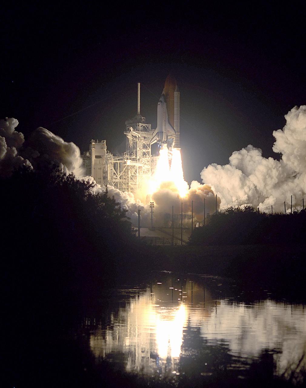
Nearby waters reflect the flames of the Space Shuttle Endeavor as she lifts off November 30, 2000 carrying the STS-97 crew of five. The STS-97 mission's primary objective was the delivery, assembly, and activation of the U.S. electrical power system onboard the International Space Station (ISS). The electrical power system, which is built into a 73-meter (240-foot) long solar array structure, consists of solar arrays, radiators, batteries, and electronics. The entire 15.4-metric ton (17-ton) package is called the P6 Integrated Truss Segment, and is the heaviest and largest element yet delivered to the station aboard a space shuttle. The electrical system will eventually provide the power necessary for the first ISS crews to live and work in the U.S. segment.
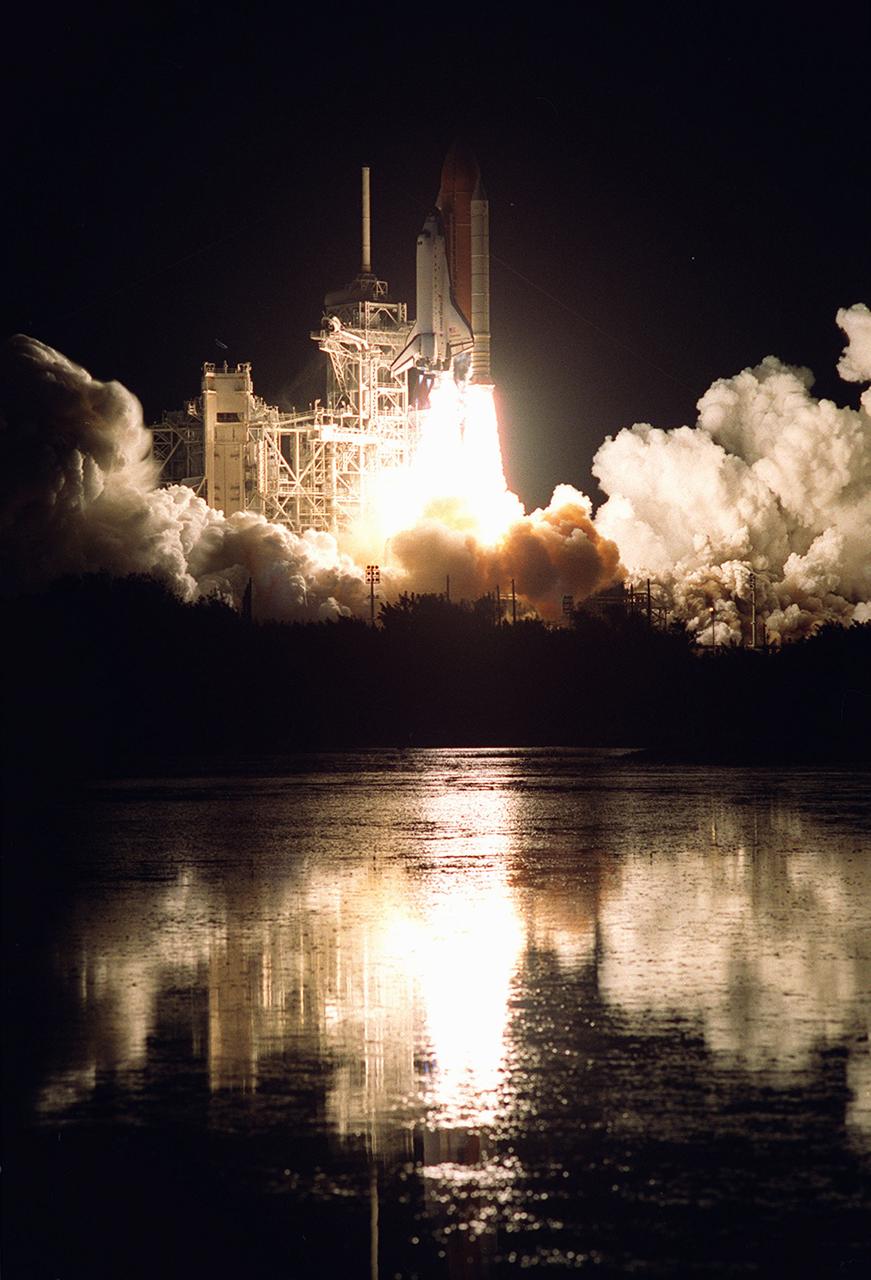
Nearby waters reflect the flames of the Space Shuttle Endeavor as she lifts off November 30, 2000, carrying the STS-97 crew of five. The STS-97 mission's primary objective was the delivery, assembly, and activation of the U.S. electrical power system onboard the International Space Station (ISS). The electrical power system, which is built into a 73-meter (240-foot) long solar array structure, consists of solar arrays, radiators, batteries, and electronics. The entire 15.4-metric ton (17-ton) package is called the P6 Integrated Truss Segment and is the heaviest and largest element yet delivered to the station aboard a space shuttle. The electrical system will eventually provide the power necessary for the first ISS crews to live and work in the U.S. segment.
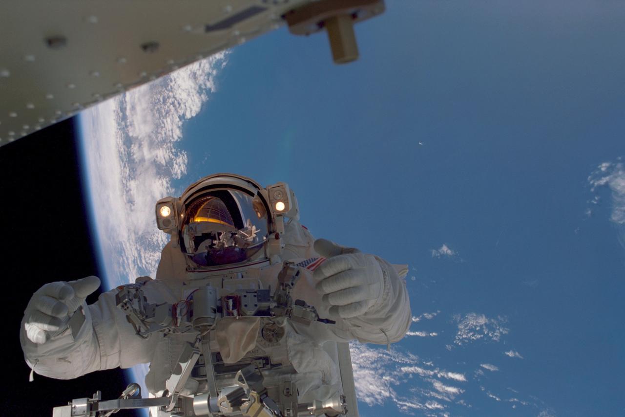
In this image, planet Earth, some 235 statute miles away, forms the back drop for this photo of STS-97 astronaut and mission specialist Joseph R. Tanner, taken during the third of three space walks. The mission's goal was to perform the delivery, assembly, and activation of the U.S. electrical power system onboard the International Space Station (ISS). The electrical power system, which is built into a 73-meter (240-foot) long solar array structure consists of solar arrays, radiators, batteries, and electronics. The entire 15.4-metric ton (17-ton) package is called the P6 Integrated Truss Segment, and is the heaviest and largest element yet delivered to the station aboard a space shuttle. The electrical system will eventually provide the power necessary for the first ISS crews to live and work in the U.S. segment. The STS-97 crew of five launched aboard the Space Shuttle Orbiter Endeavor on November 30, 2000 for an 11 day mission.

S71-44671 (30 July 1971) --- A near vertical view of the Hadley-Apennine area, as photographed by the Fairchild metric camera in the Scientific Instrumentation Module (SIM) bay of the Apollo 15 Command and Service Modules (CSM) in lunar orbit. This picture was taken shortly after the Lunar Module (LM) touched down on the moon. Hadley Rille meanders through the lower center of the picture. The Apennine Mountains dominate the picture. The LM landing site is on the east side of the rille's "chicken beak" in the center of the picture. The crater Hadley C is near the center of the photograph at the west edge of the rille. North will be at the top if the photo is held with the dark mare are on the left. The smooth, dark area is the Marsh of Decay. The three-inch mapping camera was one of eight lunar orbital science experiments mounted in the SIM bay.
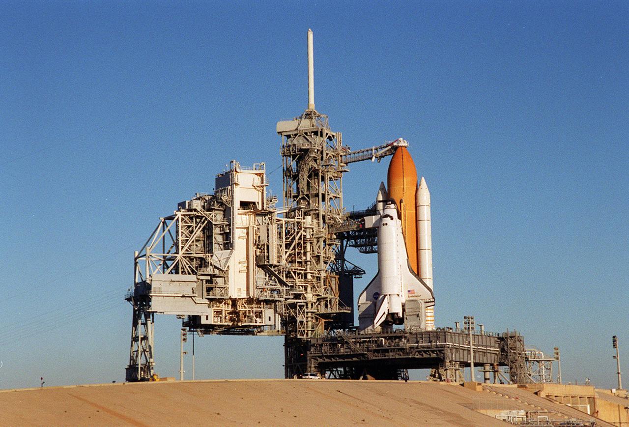
Back dropped by a cloudless blue sky, Space Shuttle Endeavor stands ready for launch after the rollback of the Rotating Service Structure, at left. The orbiter launched that night carrying the STS-97 crew of five. The STS-97 mission's primary objective was the delivery, assembly, and activation of the U.S. electrical power system onboard the International Space Station (ISS). The electrical power system, which is built into a 73-meter (240-foot) long solar array structure, consists of solar arrays, radiators, batteries, and electronics. The entire 15.4-metric ton (17-ton) package is called the P6 Integrated Truss Segment, and is the heaviest and largest element yet delivered to the station aboard a space shuttle. The electric system will eventually provide the power necessary for the first ISS crews to live and work in the U.S. segment.
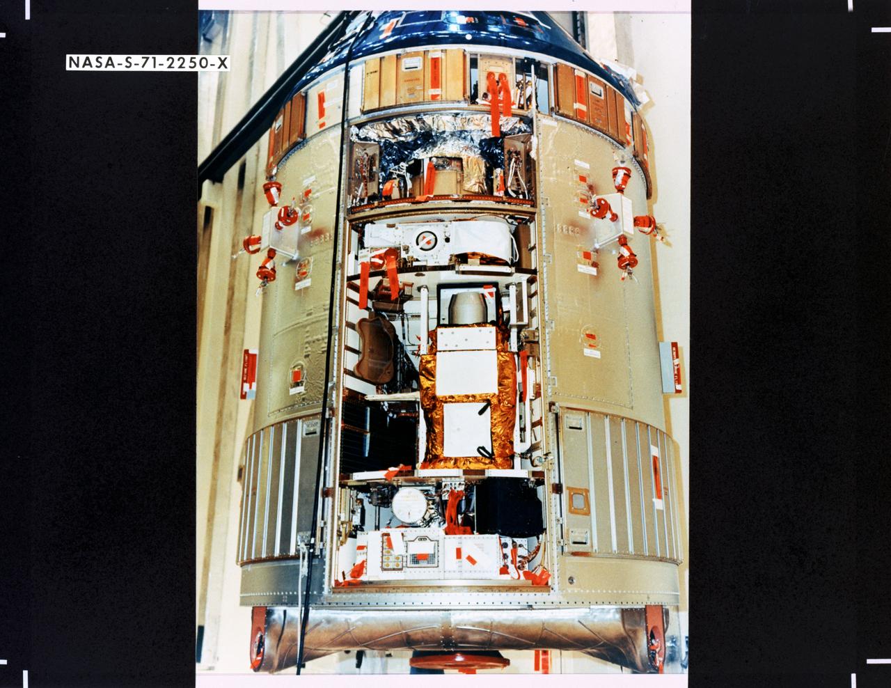
S71-2250X (June 1971) --- A close-up view of the Scientific Instrument Module (SIM) to be flown for the first time on the Apollo 15 lunar landing mission. Mounted in a previously vacant sector of the Apollo Service Module (SM), the SIM carries specialized cameras and instrumentation for gathering lunar orbit scientific data. SIM equipment includes a laser altimeter for accurate measurement of height above the lunar surface; a large-format panoramic camera for mapping, correlated with a metric camera and the laser altimeter for surface mapping; a gamma ray spectrometer on a 25-feet extendible boom; a mass spectrometer on a 21-feet extendible boom; X-ray and alpha particle spectrometers; and a subsatellite which will be injected into lunar orbit carrying a particle and magnetometer, and the S-Band transponder.
S71-44666 (31 July-2 Aug. 1971) --- An oblique view of Schroeter's Valley and the crater Aristarchus, as photographed by the Fairchild metric camera in the Scientific Instrumentation Module (SIM) bay of the Apollo 15 Command and Service Module (CSM) in lunar orbit. This view is looking south. The large, bright-appearing crater to the left of the head of meandering Schroeter's Valley is Aristarchus, the center of which is located at 48 degrees west longitude and 214 degrees north latitude. The crater Aristarchus approximately 35 kilometers (about 21.75 statute miles) in diameter. The head of Schroeter's Valley, a sinuous rille in the Aristarchus Plateau in the Ocean of Storms, is called Cobra Head. Herodotus the crater just above and to the right of Cobra Head in upper center. The three-inch mapping camera was one of eight lunar orbital science experiments mounted in the SIM bay.

This illustration shows the events that occur in the final minutes of the nearly seven-month journey that NASA's Perseverance rover takes to Mars. Hundreds of critical events must execute perfectly and exactly on time for the rover to land on Mars safely on Feb. 18, 2021. A metric version of this illustration is also available (Figure 1). Entry, Descent, and Landing, or "EDL," begins when the spacecraft reaches the top of the Martian atmosphere, traveling nearly 12,500 mph (20,000 kph). It ends about seven minutes later, with Perseverance stationary on the Martian surface. Perseverance handles everything on its own during this process. It takes more than 11 minutes to get a radio signal back from Mars, so by the time the mission team hears that the spacecraft has entered the atmosphere, in reality, the rover is already on the ground. https://photojournal.jpl.nasa.gov/catalog/PIA24285
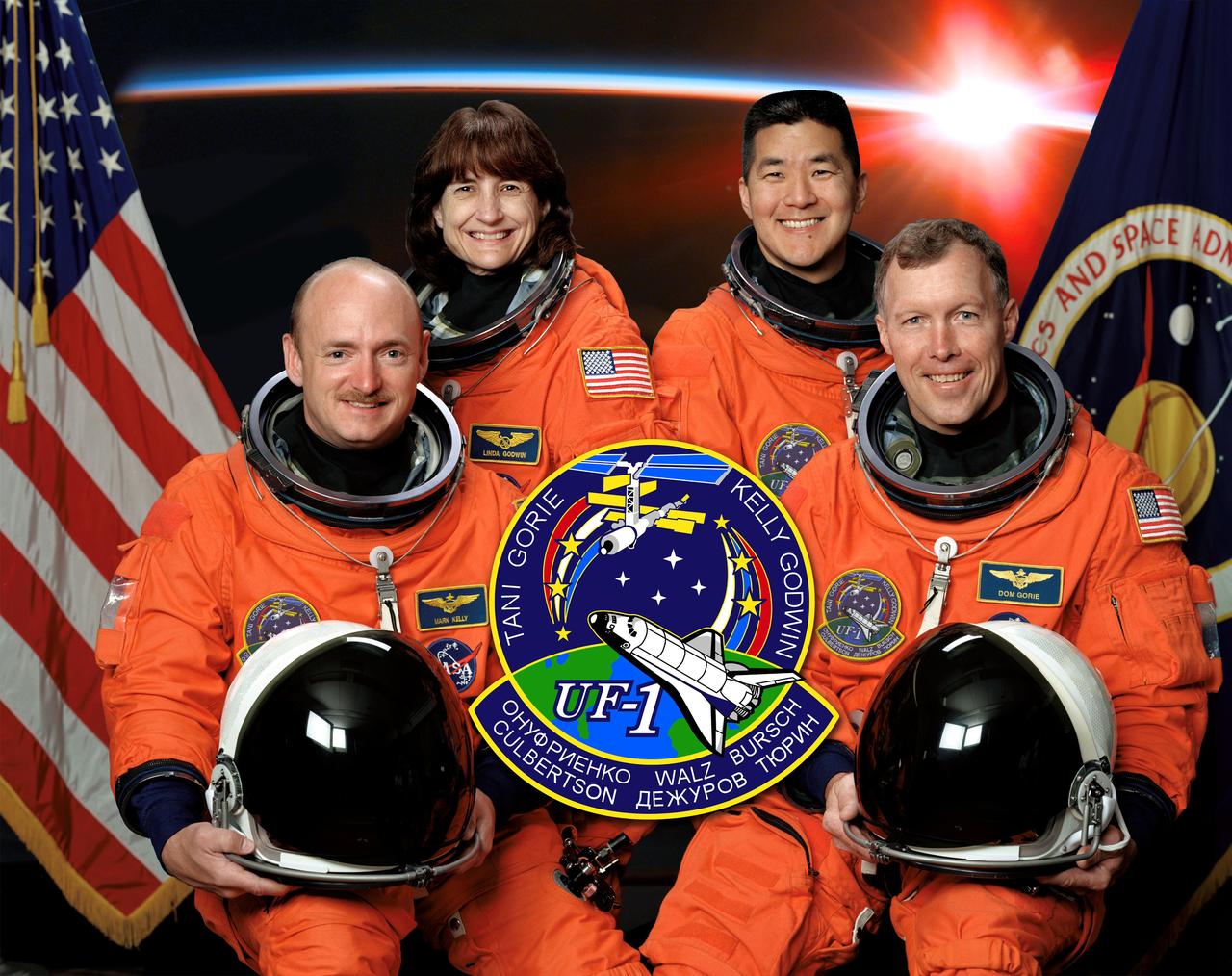
The STS-108 crew members take a break from their training to pose for their preflight portrait. Astronauts Dominic L. Gorie right) and Mark E. Kelly, commander and pilot, respectively, are seated in front. In the rear are astronauts Linda M. Godwin and Daniel L. Tani, both mission specialists. The 12th flight to the International Space Station (ISS) and final flight of 2001, the STS-108 mission launched aboard the Space Shuttle Endeavour on December 5, 2001. They were accompanied to the ISS by the Expedition Four crew, which remained on board the orbital outpost for several months. The Expedition Three crew members returned home with the STS-108 astronauts. In addition to the Expedition crew exchange, STS-108 crew deployed the student project STARSHINE, and delivered 2.7 metric tons (3 tons) of equipment and supplies to the ISS.
In this image, STS-97 astronaut and mission specialist Carlos I. Noriega waves at a crew member inside Endeavor's cabin during the mission's final session of Extravehicular Activity (EVA). Launched aboard the Space Shuttle Orbiter Endeavor on November 30, 2000, the STS-97 mission's primary objective was the delivery, assembly, and activation of the U.S. electrical power system onboard the International Space Station (ISS). The electrical power system, which is built into a 73-meter (240-foot) long solar array structure consists of solar arrays, radiators, batteries, and electronics. The entire 15.4-metric ton (17-ton) package is called the P6 Integrated Truss Segment, and is the heaviest and largest element yet delivered to the station aboard a space shuttle. The electrical system will eventually provide the power necessary for the first ISS crews to live and work in the U.S. segment.

An expanded view of comet C/2006 W3 (Christensen) is shown here. The WISE spacecraft observed this comet on April 20th, 2010 as it traveled through the constellation Sagittarius. Comet Christensen was nearly 370 million miles (600 million kilometers) from Earth at the time. The extent of the dust, about a tenth of a degree across in this image, is about 2/3rds the diameter of the sun. The red contours show the signal from the gas emission observed by the WISE spacecraft in the 4.6 micron wavelength channel, which contains carbon monoxide (CO) and carbon dioxide (CO2) emission lines. The strength of the 4.6 micron signal indicates over half a metric ton per second of CO or CO2 was emitted from this comet at the time of the observations. The WISE spacecraft was put into hibernation in 2011 upon completing its goal of surveying the entire sky in infrared light. WISE cataloged three quarters of a billion objects, including asteroids, stars and galaxies. In August 2013, NASA decided to reinstate the spacecraft on a mission to find and characterize more asteroids. http://photojournal.jpl.nasa.gov/catalog/PIA20119
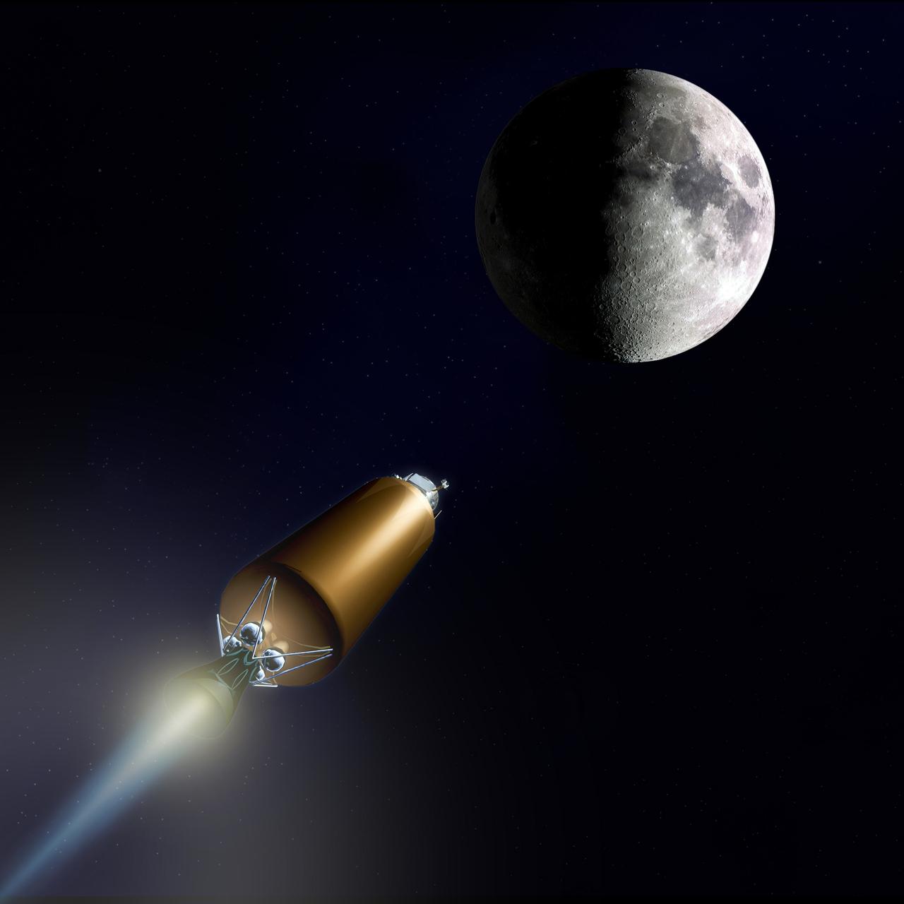
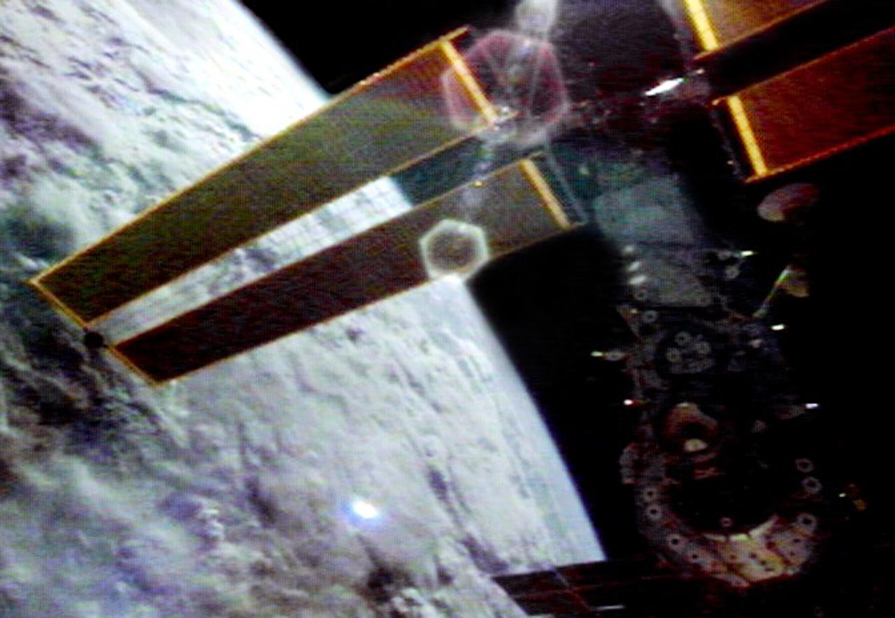
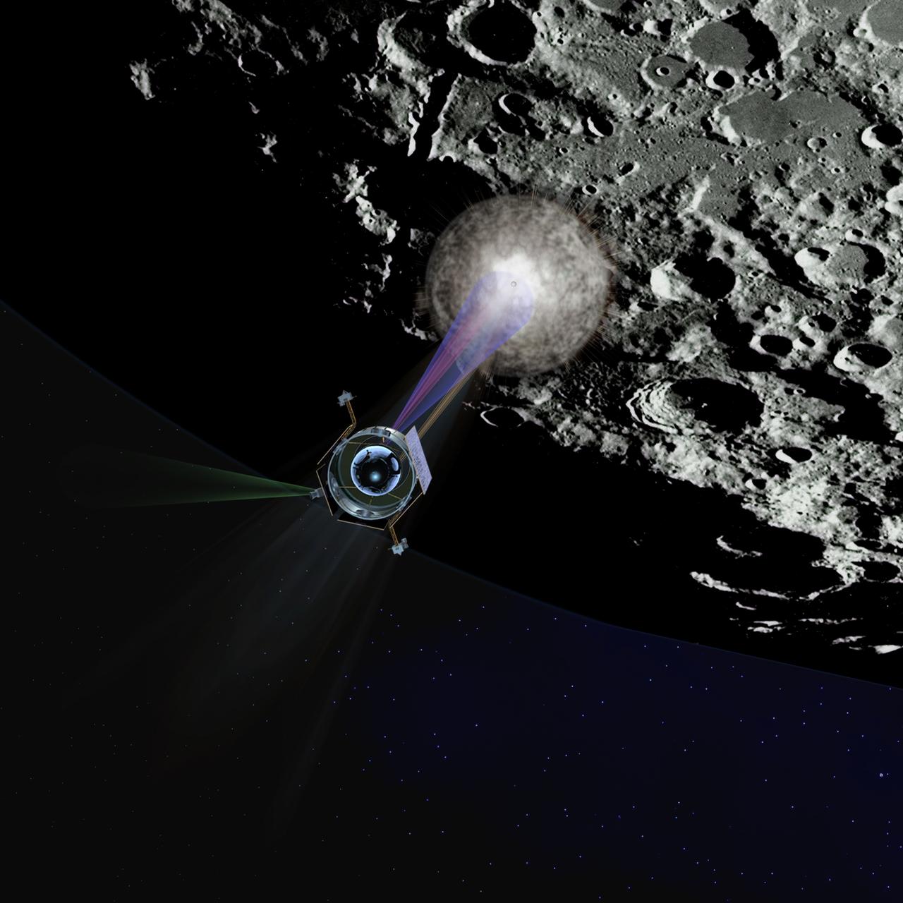
LCROSS (Lunar CRater Observation and Sensing Satellite) Mission Art IMAGES COURTESY OF NORTHROP GRUMMAN, WILLIAM FURLONG, ARTIST This NASA Ames spacecraft is a small 'secondary payload' spacecraft that will travel with Lunar Reconnaissance Obriter (LRO) satellite to the moon on the same rocket, the Evolved Expendable Launch Vehicle (EELV) to be launched from Kennedy Space Center, Florida in a search for water ice on the moon's south polar region. As the spacecraft approaches the moon's south pole, the upper stge will separate, and then will impact a crater in the south pole area. A plume from the upper stage crash will develope as the Shepherding Spacecraft heads in toward the moon. The Shepherding Spacecrat will fly through the plume, and instruments on the spacecraft wil analyze the cloud to look for signs of water and other compounds. Additional space and Earth-based instruments will study the 2.2-millon-pound (1000-metric-ton) plume. 'The LCROSS mission will help us to determine if there is water hidden in the permanently dark craters on the moon's south pole.' said Marvin( (Chris) Christensen, Robotic Lunar Exploration Program (RLEP) manager, and Deputy Director of NASA Ames.
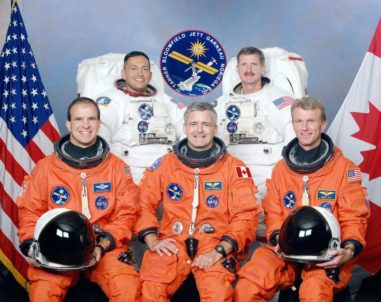
These five STS-97 crew members posed for a traditional portrait during training. On the front row, left to right, are astronauts Michael J. Bloomfield, pilot; Marc Garneau, mission specialist representing the Canadian Space Agency (CSA); and Brent W. Jett, Jr., commander. In the rear, wearing training versions of the extravehicular mobility unit (EMU) space suits, (left to right) are astronauts Carlos I. Noriega, and Joseph R. Tarner, both mission specialists. The primary objective of the STS-97 mission was the delivery, assembly, and activation of the U.S. electrical power system onboard the International Space Station (ISS). The electrical power system, which is built into a 73-meter (240-foot) long solar array structure consists of solar arrays, radiators, batteries, and electronics. The entire 15.4-metric ton (17-ton) package is called the P6 Integrated Truss Segment and is the heaviest and largest element yet delivered to the station aboard a space shuttle. The electrical system will eventually provide the power necessary for the first ISS crews to live and work in the U.S. segment. The STS-97 crew of five launched aboard the Space Shuttle Orbiter Endeavor on November 30, 2000 for an 11 day mission.
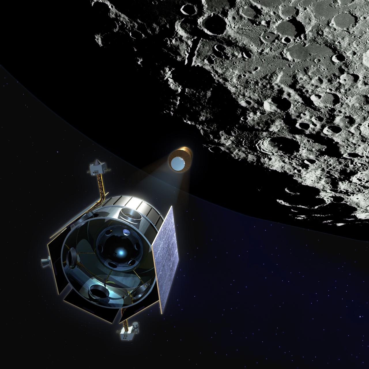
LCROSS (Lunar CRater Observation and Sensing Satellite) Mission Art IMAGES COURTESY OF NORTHROP GRUMMAN, WILLIAM FURLONG, ARTIST This NASA Ames spacecraft is a small 'secondary payload' spacecraft that will travel with Lunar Reconnaissance Obriter (LRO) satellite to the moon on the same rocket, the Evolved Expendable Launch Vehicle (EELV) to be launched from Kennedy Space Center, Florida in a search for water ice on the moon's south polar region. As the spacecraft approaches the moon's south pole, the upper stge will separate, and then will impact a crater in the south pole area. A plume from the upper stage crash will develope as the Shepherding Spacecraft heads in toward the moon. The Shepherding Spacecrat will fly through the plume, and instruments on the spacecraft wil analyze the cloud to look for signs of water and other compounds. Additional space and Earth-based instruments will study the 2.2-millon-pound (1000-metric-ton) plume. 'The LCROSS mission will help us to determine if there is water hidden in the permanently dark craters on the moon's south pole.' said Marvin( (Chris) Christensen, Robotic Lunar Exploration Program (RLEP) manager, and Deputy Director of NASA Ames.
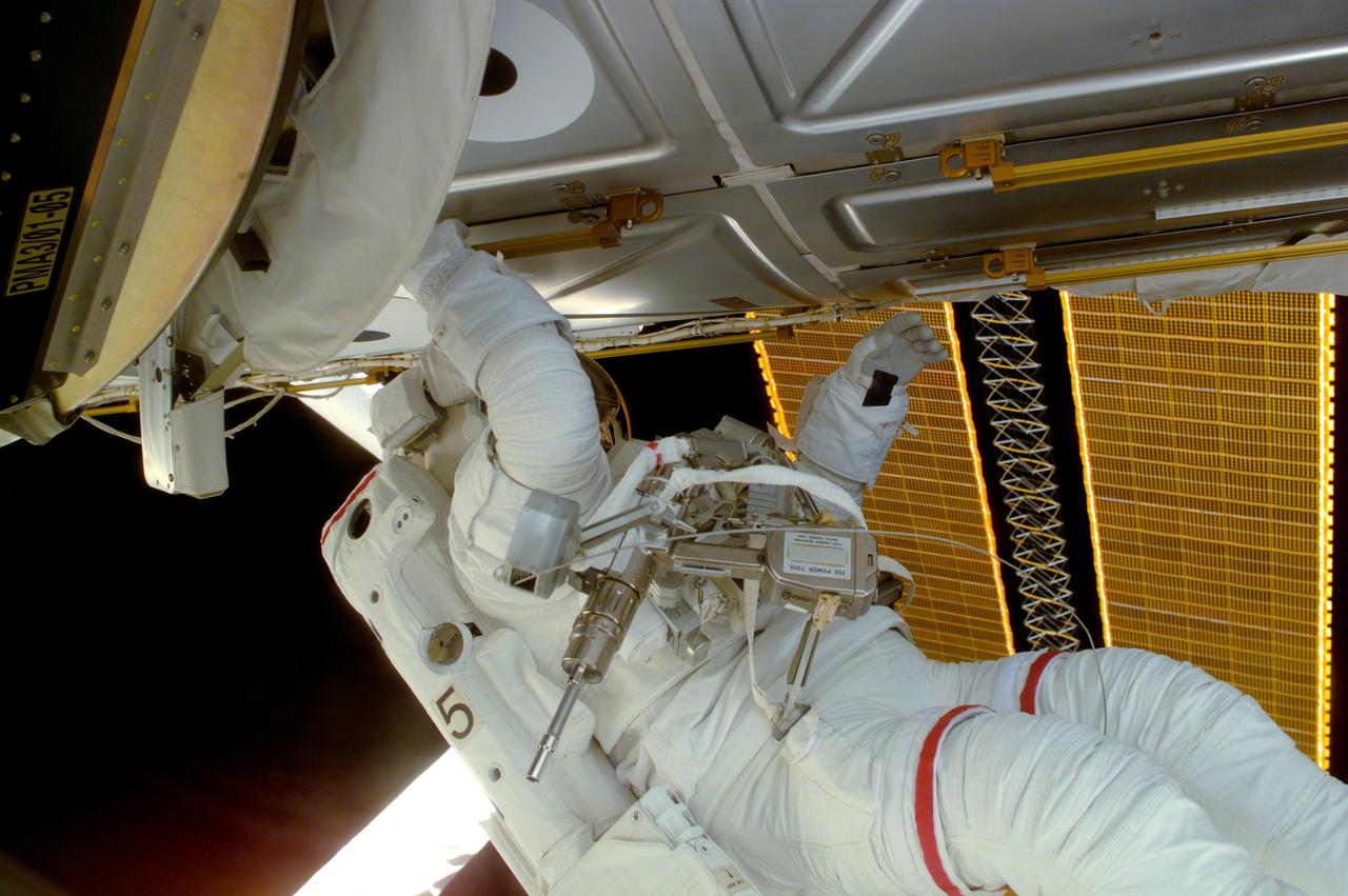
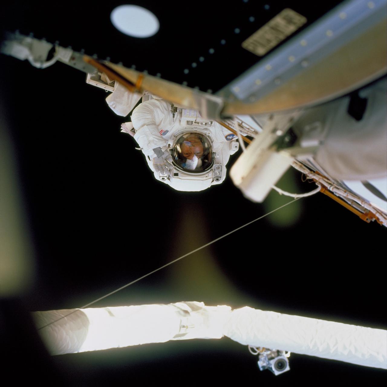
Astronaut Joseph R. Tanner, STS-97 mission specialist, is seen during a session of Extravehicular Activity (EVA), performing work on the International Space Station (ISS). Part of the Remote Manipulator System (RMS) arm and a section of the newly deployed solar array panel are in the background. The primary objective of the STS-97 mission was the delivery, assembly, and activation of the U.S. electrical power system on board the ISS. The electrical power system, which is built into a 73-meter (240-foot) long solar array structure consists of solar arrays, radiators, batteries, and electronics. The entire 15.4-metric ton (17-ton) package is called the P6 Integrated Truss Segment and is the heaviest and largest element yet delivered to the station aboard a space shuttle. The electrical system will eventually provide the power necessary for the first ISS crews to live and work in the U.S. segment. The STS-97 crew of five launched aboard the Space Shuttle Orbiter Endeavor on November 30, 2000 for an 11 day mission.
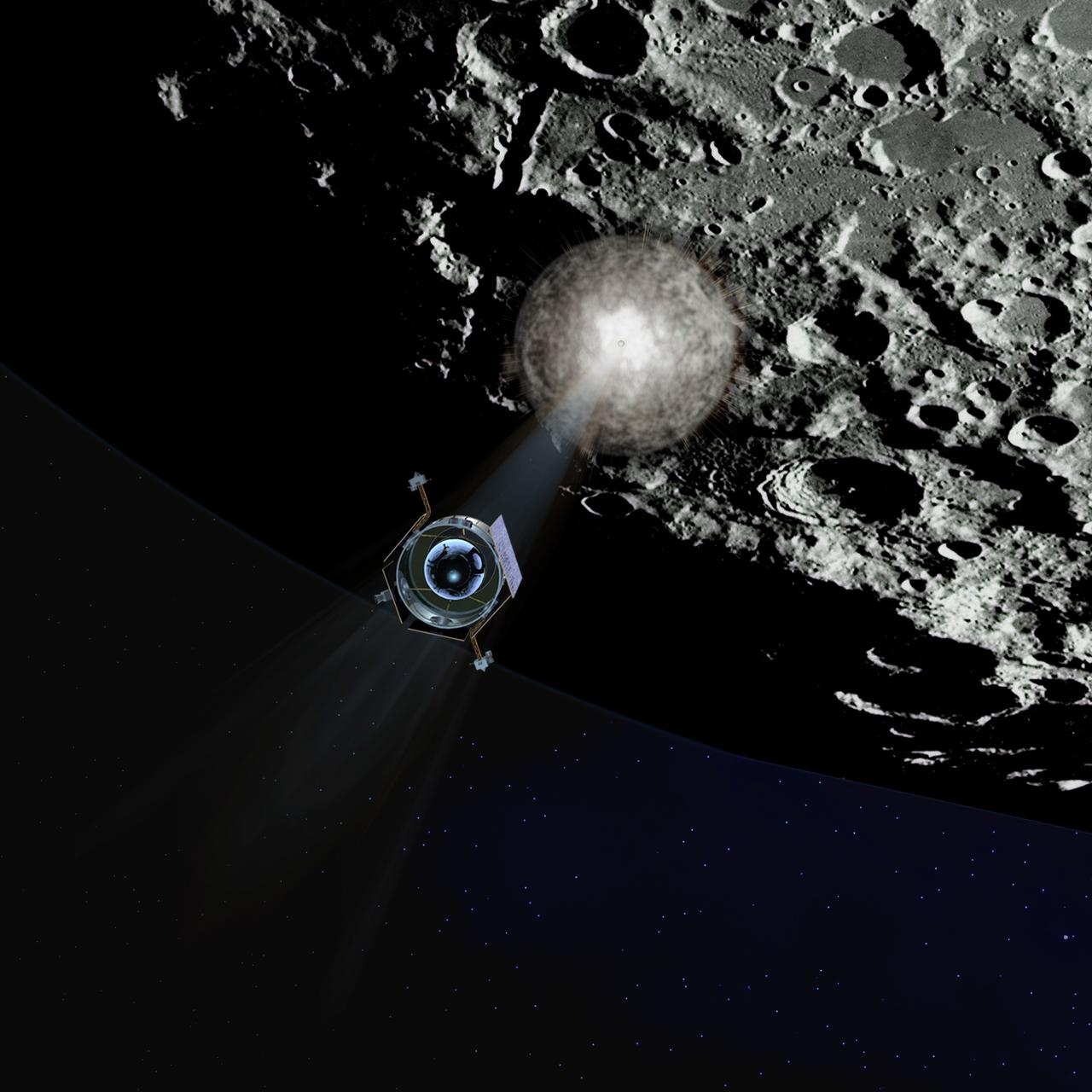
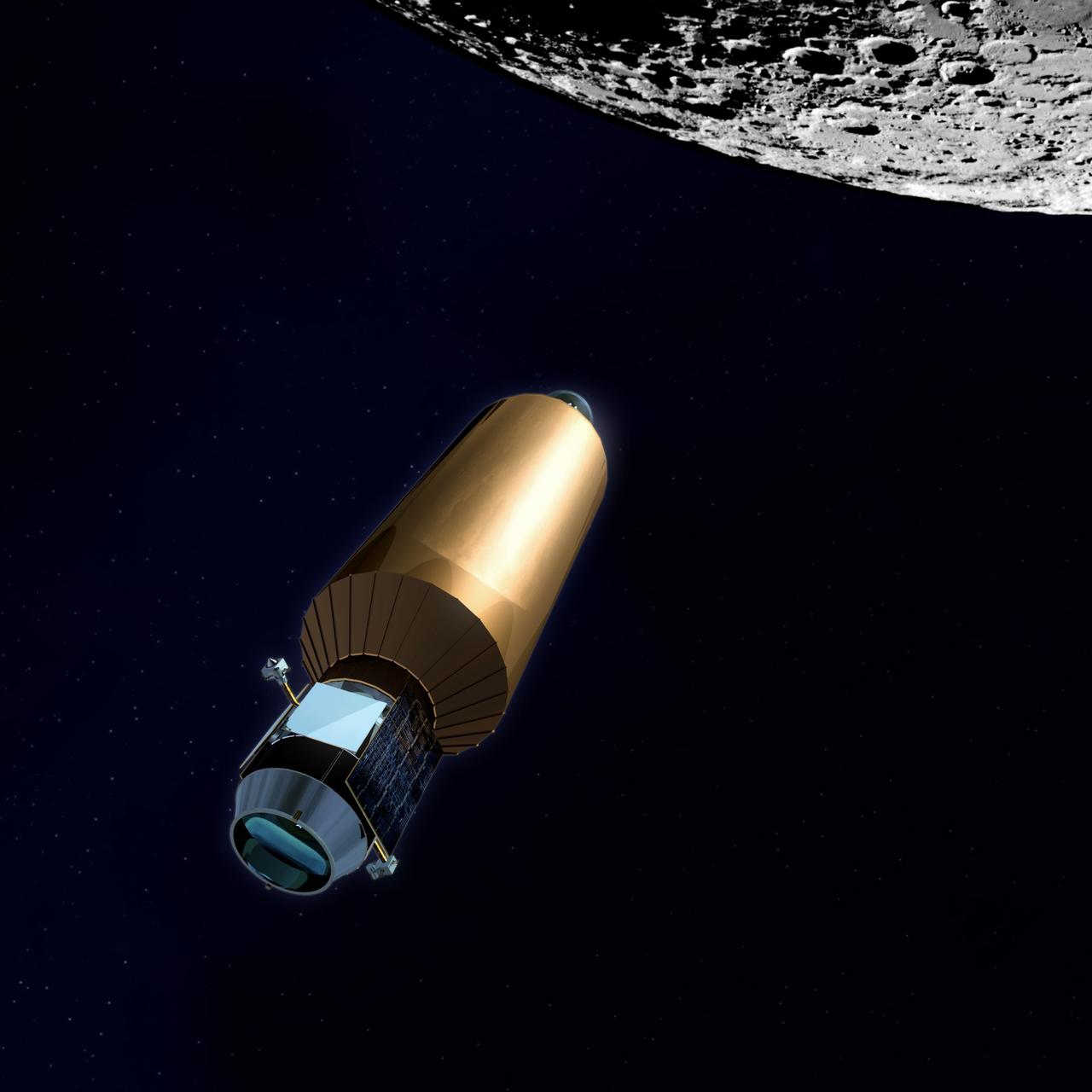
LCROSS (Lunar CRater Observation and Sensing Satellite) Mission Art IMAGES COURTESY OF NORTHROP GRUMMAN, WILLIAM FURLONG, ARTIST This NASA Ames spacecraft is a small 'secondary payload' spacecraft that will travel with Lunar Reconnaissance Obriter (LRO) satellite to the moon on the same rocket, the Evolved Expendable Launch Vehicle (EELV) to be launched from Kennedy Space Center, Florida in a search for water ice on the moon's south polar region. As the spacecraft approaches the moon's south pole, the upper stge will separate, and then will impact a crater in the south pole area. A plume from the upper stage crash will develope as the Shepherding Spacecraft heads in toward the moon. The Shepherding Spacecrat will fly through the plume, and instruments on the spacecraft wil analyze the cloud to look for signs of water and other compounds. Additional space and Earth-based instruments will study the 2.2-millon-pound (1000-metric-ton) plume. 'The LCROSS mission will help us to determine if there is water hidden in the permanently dark craters on the moon's south pole.' said Marvin( (Chris) Christensen, Robotic Lunar Exploration Program (RLEP) manager, and Deputy Director of NASA Ames.
At the control of Expedition Two Flight Engineer Susan B. Helms, the newly-installed Canadian-built Canadarm2, Space Station Remote Manipulator System (SSRMS) maneuvers the Quest Airlock into the proper position to be mated onto the starboard side of the Unity Node I during the first of three extravehicular activities (EVA) of the STS-104 mission. The Quest Airlock makes it easier to perform space walks, and allows both Russian and American spacesuits to be worn when the Shuttle is not docked with the International Space Station (ISS). American suits will not fit through Russion airlocks at the Station. The Boeing Company, the space station prime contractor, built the 6.5-ton (5.8 metric ton) airlock and several other key components at the Marshall Space Flight Center (MSFC), in the same building where the Saturn V rocket was built. Installation activities were supported by the development team from the Payload Operations Control Center (POCC) located at the MSFC and the Mission Control Center at NASA's Johnson Space Flight Center in Houston, Texas.
LCROSS (Lunar CRater Observation and Sensing Satellite) Mission Art IMAGES COURTESY OF NORTHROP GRUMMAN, WILLIAM FURLONG, ARTIST This NASA Ames spacecraft is a small 'secondary payload' spacecraft that will travel with Lunar Reconnaissance Obriter (LRO) satellite to the moon on the same rocket, the Evolved Expendable Launch Vehicle (EELV) to be launched from Kennedy Space Center, Florida in a search for water ice on the moon's south polar region. As the spacecraft approaches the moon's south pole, the upper stge will separate, and then will impact a crater in the south pole area. A plume from the upper stage crash will develope as the Shepherding Spacecraft heads in toward the moon. The Shepherding Spacecrat will fly through the plume, and instruments on the spacecraft wil analyze the cloud to look for signs of water and other compounds. Additional space and Earth-based instruments will study the 2.2-millon-pound (1000-metric-ton) plume. 'The LCROSS mission will help us to determine if there is water hidden in the permanently dark craters on the moon's south pole.' said Marvin( (Chris) Christensen, Robotic Lunar Exploration Program (RLEP) manager, and Deputy Director of NASA Ames.

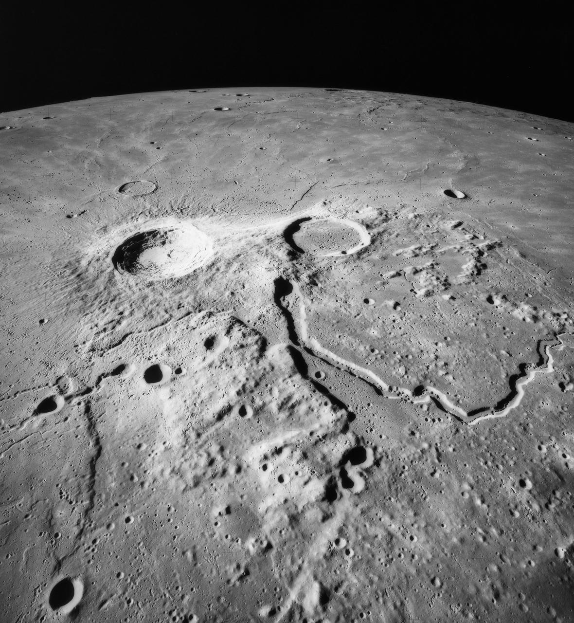
S71-44667 (31 July-2 Aug. 1971) --- An oblique view of the Hadley-Apennine area, looking north, as photographed by the Fairchild metric camera in the Scientific Instrumentation Module (SIM) bay of the Apollo 15 Command and Service Modules (CSM) in lunar orbit. Hadley Rille meanders through the lower center of the picture. The Apennine Mountains are at lower right. The Apollo 15 Lunar Module (LM) touchdown point is on the east side of the "chicken beak" of Hadley Rille. The Caucasus Mountains are at upper right. The dark mare area at the extreme upper right is a portion of the Sea of Serenity. The Marsh of Decay is at lower left. The large crater near the horizon is Aristillus, which is about 55 kilometers (34.18 statute miles) in diameter. The crater just to the south of Aristillus is Autolycus, which is about 40 kilometers (25 statute miles) in diameter. The crater Cassini is barely visible on the horizon at upper right. The three-inch mapping camera was one of eight lunar orbital science experiments mounted in the SIM bay.
LCROSS (Lunar CRater Observation and Sensing Satellite) Mission Art IMAGES COURTESY OF NORTHROP GRUMMAN, WILLIAM FURLONG, ARTIST This NASA Ames spacecraft is a small 'secondary payload' spacecraft that will travel with Lunar Reconnaissance Obriter (LRO) satellite to the moon on the same rocket, the Evolved Expendable Launch Vehicle (EELV) to be launched from Kennedy Space Center, Florida in a search for water ice on the moon's south polar region. As the spacecraft approaches the moon's south pole, the upper stge will separate, and then will impact a crater in the south pole area. A plume from the upper stage crash will develope as the Shepherding Spacecraft heads in toward the moon. The Shepherding Spacecrat will fly through the plume, and instruments on the spacecraft wil analyze the cloud to look for signs of water and other compounds. Additional space and Earth-based instruments will study the 2.2-millon-pound (1000-metric-ton) plume. 'The LCROSS mission will help us to determine if there is water hidden in the permanently dark craters on the moon's south pole.' said Marvin( (Chris) Christensen, Robotic Lunar Exploration Program (RLEP) manager, and Deputy Director of NASA Ames.
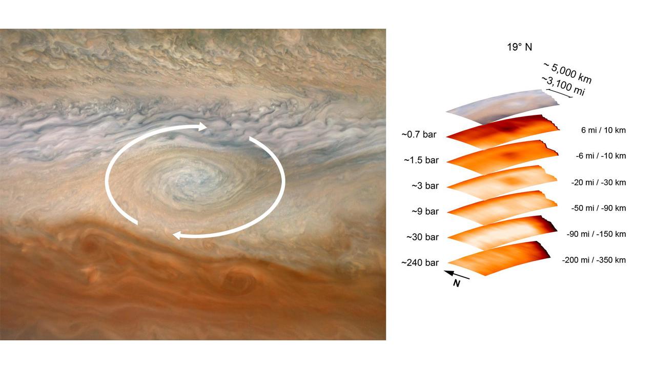
The image on the left, taken by the JunoCam imager aboard NASA's Juno spacecraft, has been annotated to depict the clockwise rotation of a vortex at Jupiter. The graphic on the right highlights the large-scale structure of the feature as seen by the spacecraft's microwave radiometer (MWR) instrument. Data for the image and the microwave radiometer results were collected during a low flyby of Jupiter that took place on July 21, 2019. The radiometer data was acquired from the six channels of MWR. Each MWR channel peers progressively deeper below the visible cloud tops. In fact, the MWR instrument enables Juno to see deeper into Jupiter than any previous spacecraft or Earth-based observations. Unlike Earth, which as a solid surface, Jupiter is a gas giant with no discernable solid surface. So the planetary science community has defined the "base" of Jupiter's atmosphere as the location where its pressure is equivalent to 1 bar. A bar is a metric unit of pressure that, at 14.5 pounds per square inch, is slightly less than the average atmospheric pressure on Earth at sea level. The numbers to the left of each layer of MWR data above indicate the pressure at the location in the atmosphere where the MWR reading occurred. The measurements to the right of each layer of MWR data provide the distance – either above or below the 1 bar level – from which the corresponding MWR measurement was taken. For context, the top layer in the figure is a visible-light image depicting Jupiter's different levels of clouds, with an average altitude about 6 miles above the 1 bar pressure region. https://photojournal.jpl.nasa.gov/catalog/PIA24975
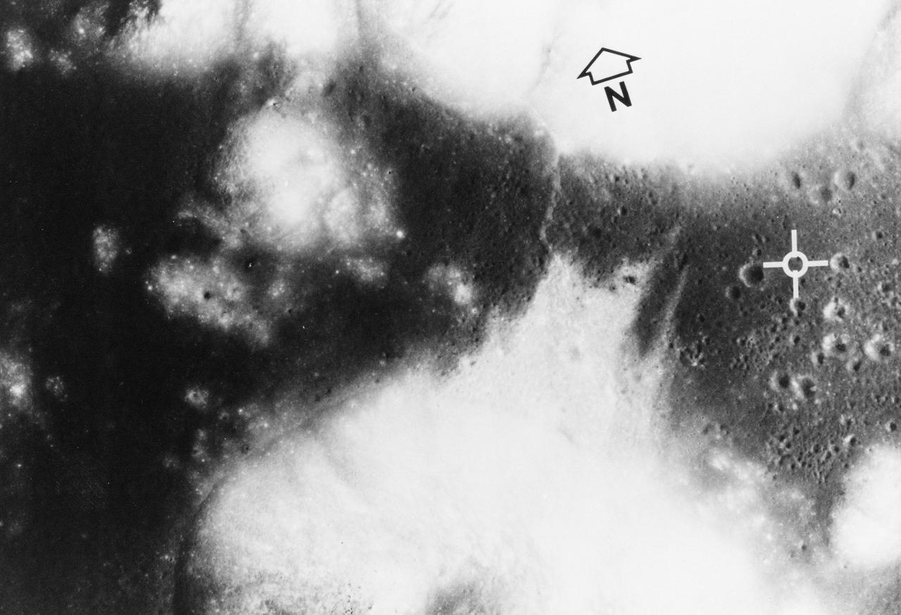
S72-35010 (April 1972) --- The Apollo Program's final manned landing on the moon will explore a site designated Taurus-Littrow on the southeastern rim of the Sea of Serenity. This photograph from the Apollo 15 Metric Camera gives a vertical view of the Apollo 17 landing site at 20 degrees north latitude and 30 degrees east longitude. The site (white cross) is on a dark-cratered plain at the base of light-colored highland mountains. The major scientific objective is to study the highlands for new knowledge about what is believed to be representative of the most ancient part of the moon. The darker material forms a bay amid steep-sided mountains that rise almost 2 kilometers (1 1/4 miles) above the adjacent plain or basin. Mountain slopes in excess of 25 degrees are common. The individual mountain masses and ridges are believed to represent very old highland crustal blocks structurally separated by various basin-forming events. The basin and parts of the highlands are mantled (covered) with dark deposits that may be fragmented rocks of volcanic origin. The dark mantle, a very low albedo, (low light-reflective) loose material which covers pre-existing terrain, is extensively developed in this region. Sampling of the dark deposits is given a high priority since its age and composition wouls shed light on the thermal history of the moon. Panoramic photography and command module pilot observations on Apollo 15 documented the presence here of a number of cinder cones which may be related to the dark mantle. It might be dust blown out by a volcanic eruption. Radar maps indicate this dark mantle is different because of its scarcity of block material. The photo covers 22 kilometers (13.5 miles) from east to west and 15 kilometers (9 miles) north to south. A ridge-like feature snakes from north to south across the basin and highlands about 6 kilometers (3.7 miles) west of the landing point, and is partly covered by a northward debris flow from the base of a mountain southwest
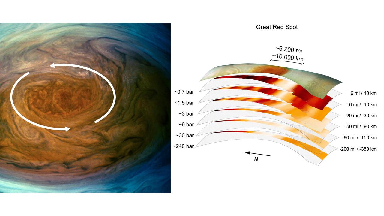
The annotated image on the left from the JunoCam imager aboard NASA's Juno spacecraft depicts the anticyclonic (counterclockwise) rotation of Jupiter's Great Red Spot. The graphic on the right highlights the large-scale structure of the Great Red Spot as seen by the spacecraft's microwave radiometer (MWR) instrument. Data for the image and the microwave radiometer results were collected during a low flyby of Jupiter which took place on July 11, 2017. The radiometer data was acquired from the six channels of MWR. Each MWR channel peers progressively deeper below the visible cloud tops. In fact, the MWR instrument enables Juno to see deeper into Jupiter than any previous spacecraft or Earth-based observations. Unlike Earth, which as a solid surface, Jupiter is a gas giant with no discernable solid surface. So the planetary science community has defined the "base" of Jupiter's atmosphere to be defined as the location where its pressure is equivalent to is 1 bar. The bar is a metric unit of pressure which at 14.5 pounds per square inch is slightly less than the average atmospheric pressure on Earth at sea level. The numbers noted to the left of each layer of MWR data indicates the pressure (in bars) that is present at the location in the atmosphere where the MWR reading occurred. The distance measurements to the right of each layer of MWR data provides the distance – either above or below the 1 bar level – that the corresponding MWR measurement was taken. For context, the top layer in the figure is a visible-light image depicting Jupiter's different levels of clouds, with an average altitude about 6 miles above the 1 bar pressure region. https://photojournal.jpl.nasa.gov/catalog/PIA24819

In this image, the five STS-97 crew members pose with the 3 members of the Expedition One crew onboard the International Space Station (ISS) for the first ever traditional onboard portrait taken in the Zvezda Service Module. On the front row, left to right, are astronauts Brent W. Jett, Jr., STS-97 commander; William M. Shepherd, Expedition One mission commander; and Joseph R. Tarner, STS-97 mission specialist. On the second row, from the left are Cosmonaut Sergei K. Krikalev, Expedition One flight engineer; astronaut Carlos I. Noriega, STS-97 mission specialist; cosmonaut Yuri P. Gidzenko, Expedition One Soyuz commander; and Michael J. Bloomfield, STS-97 pilot. Behind them is astronaut Marc Garneau, STS-97 mission specialist representing the Canadian Space Agency (CSA). The primary objective of the STS-97 mission was the delivery, assembly, and activation of the U.S. electrical power system onboard the International Space Station (ISS). The electrical power system, which is built into a 73-meter (240-foot) long solar array structure consists of solar arrays, radiators, batteries, and electronics. The entire 15.4-metric ton (17-ton) package is called the P6 Integrated Truss Segment, and is the heaviest and largest element yet delivered to the station aboard a space shuttle. The electrical system will eventually provide the power necessary for the first ISS crews to live and work in the U.S. segment. The STS-97 crew of five launched aboard the Space Shuttle Orbiter Endeavor on November 30, 2000 for an 11 day mission.
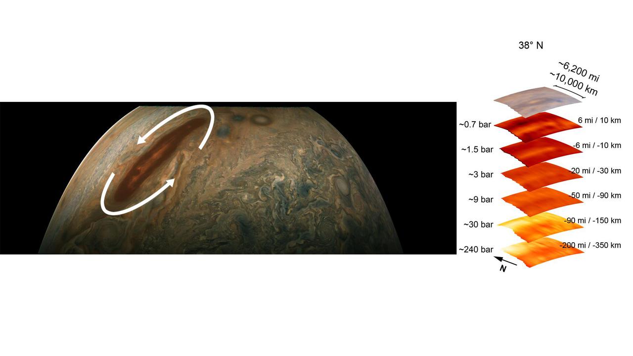
The color-enhanced image on the left is from the JunoCam imager aboard NASA's Juno spacecraft and has been annotated to depict the anticyclonic (counterclockwise) rotation of one of Jupiter's intriguing atmospheric phenomena – a long, brown oval cyclonic region known as a "brown barge." The graphic on the right highlights the large-scale structure of the brown barge as seen by the spacecraft's microwave radiometer (MWR) instrument. Data for the image and the microwave radiometer results were collected during a low flyby of Jupiter. Brown barges usually lie within Jupiter's dark North Equatorial Belt, although they are sometimes found in the similarly dark South Equatorial Belt as well. They can often be difficult to detect visually because their color blends in with the dark surroundings. Brown barges usually dissipate after the entire cloud belt undergoes an upheaval and reorganizes itself. Juno is providing the first glimpses of the detailed structure within such a barge. The radiometer data was acquired from the six channels of MWR. Each MWR channel peers progressively deeper below the visible cloud tops. In fact, the MWR instrument enables Juno to see deeper into Jupiter than any previous spacecraft or Earth-based observations. Unlike Earth, which as a solid surface, Jupiter is a gas giant with no discernable solid surface. So the planetary science community has defined the "base" of Jupiter's atmosphere as the location where its pressure is equivalent to 1 bar. The bar is a metric unit of pressure that, at 14.5 pounds per square inch, is slightly less than the average atmospheric pressure on Earth at sea level. The numbers to the left of each layer of MWR data indicates the pressure that is present at the location in the atmosphere where the MWR reading occurred. The distance measurements to the right of each layer of MWR data provides the distance – either above or below the 1 bar level – at which the corresponding MWR measurement was taken. For context, the top layer in the figure is a visible-light image depicting Jupiter's different levels of clouds, with an average altitude about 6 miles above the 1 bar pressure region. https://photojournal.jpl.nasa.gov/catalog/PIA24974