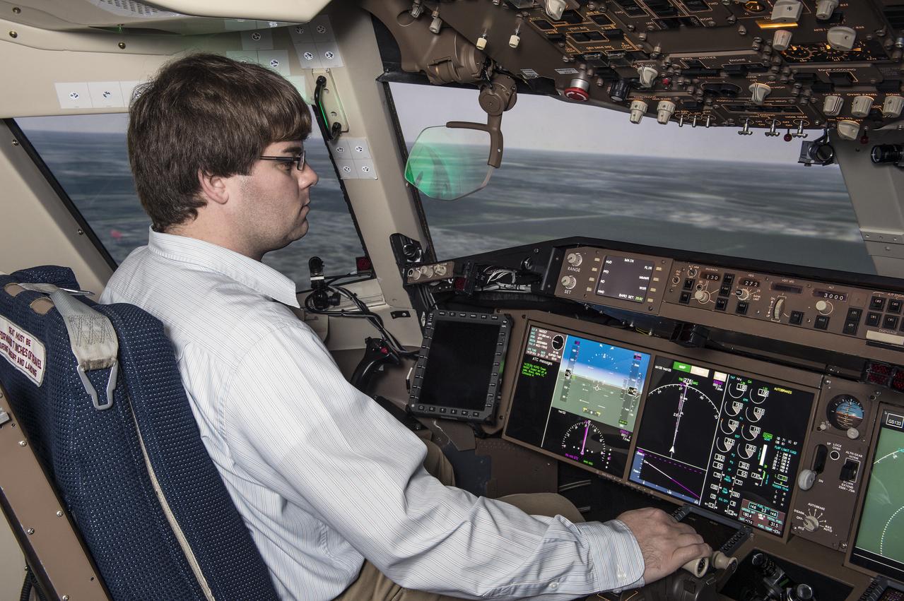
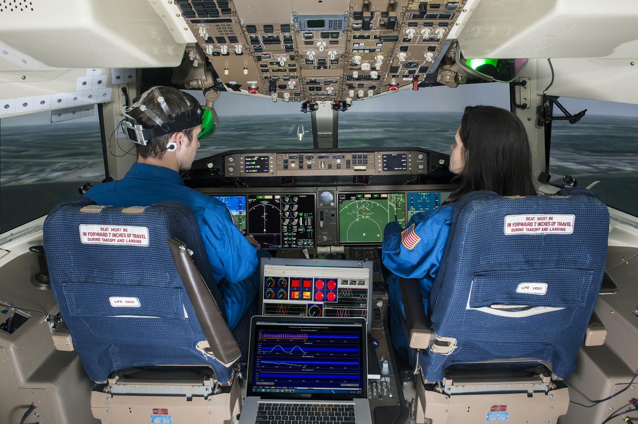
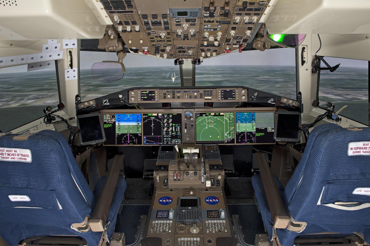
NextSafe 2.5 Motion Simulation Experiment Crew evaluation of vision system technologies
NextSafe 2.5 Motion Simulation Experiment Crew evaluation of vision system technologies
NextSafe 2.5 Motion Simulation Experiment Crew evaluation of vision system technologies
NextSafe 2.5 Motion Simulation Experiment Crew evaluation of vision system technologies

NextSafe 2.5 Motion Simulation Experiment Crew evaluation of vision system technologies

NextSafe 2.5 Motion Simulation Experiment Crew evaluation of vision system technologies

NextSafe 2.5 Motion Simulation Experiment Crew evaluation of vision system technologies

NextSafe 2.5 Motion Simulation Experiment Crew evaluation of vision system technologies
NextSafe 2.5 Motion Simulation Experiment Crew evaluation of vision system technologies
NextSafe 2.5 Motion Simulation Experiment Crew evaluation of vision system technologies
NextSafe 2.5 Motion Simulation Experiment Crew evaluation of vision system technologies
The Marshall Space Flight Center (MSFC) played a crucial role in the development of the huge Saturn rockets that delivered humans to the moon in the 1960s. Many unique facilities existed at MSFC for the development and testing of the Saturn rockets. Affectionately nicknamed “The Arm Farm”, the Random Motion/ Lift-Off Simulator was one of those unique facilities. This facility was developed to test the swingarm mechanisms that were used to hold the rocket in position until lift-off. The Arm Farm provided the capability of testing the detachment and reconnection of various arms under brutally realistic conditions. The 18-acre facility consisted of more than a half dozen arm test positions and one position for testing access arms used by the Apollo astronauts. Each test position had two elements: a vehicle simulator for duplicating motions during countdown and launch; and a section duplicating the launch tower. The vehicle simulator duplicated the portion of the vehicle skin that contained the umbilical connections and personnel access hatches. Driven by a hydraulic servo system, the vehicle simulator produced relative motion between the vehicle and tower. On the Arm Farm, extreme environmental conditions (such as a launch scrub during an approaching Florida thunderstorm) could be simulated. The dramatic scenes that the Marshall engineers and technicians created at the Arm Farm permitted the gathering of crucial technical and engineering data to ensure a successful real time launch from the Kennedy Space Center.

This in an aerial view (looking east) of a Lunar Roving Vehicle (LRV), often referred to as “Moonbuggy”, simulator area built at the Marshall Space Flight Center (MSFC) where testing was performed. The LRV was developed under the direction of MSFC to provide astronauts with greater mobility on the lunar surface. Visible in the background is the 18-acre facility known as the Random Motion/ Lift-Off Simulator or ‘Arm Farm’ which was developed to test the Saturn swingarm mechanisms that were used to hold the rocket in position until lift-off.
The Marshall Space Flight Center (MSFC) played a crucial role in the development of the huge Saturn rockets that delivered humans to the moon in the 1960s. Many unique facilities existed at MSFC for the development and testing of the Saturn rockets. Affectionately nicknamed “The Arm Farm”, the Random Motion/ Lift-Off Simulator was one of those unique facilities. This facility was developed to test the swingarm mechanisms that were used to hold the rocket in position until lift-off. The Arm Farm provided the capability of testing the detachment and reconnection of various arms under brutally realistic conditions. The 18-acre facility consisted of more than a half dozen arm test positions and one position for testing access arms used by the Apollo astronauts. Each test position had two elements: a vehicle simulator for duplicating motions during countdown and launch; and a section duplicating the launch tower. The vehicle simulator duplicated the portion of the vehicle skin that contained the umbilical connections and personnel access hatches. Driven by a hydraulic servo system, the vehicle simulator produced relative motion between the vehicle and tower. On the Arm Farm, extreme environmental conditions (such as a launch scrub during an approaching Florida thunderstorm) could be simulated. The dramatic scenes that the Marshall engineers and technicians created at the Arm Farm permitted the gathering of crucial technical and engineering data to ensure a successful real time launch from the Kennedy Space Center.
The Marshall Space Flight Center (MSFC) played a crucial role in the development of the huge Saturn rockets that delivered humans to the moon in the 1960s. Many unique facilities existed at MSFC for the development and testing of the Saturn rockets. Affectionately nicknamed “The Arm Farm”, the Random Motion/ Lift-Off Simulator was one of those unique facilities. This facility was developed to test the swingarm mechanisms that were used to hold the rocket in position until lift-off. The Arm Farm provided the capability of testing the detachment and reconnection of various arms under brutally realistic conditions. The 18-acre facility consisted of more than a half dozen arm test positions and one position for testing access arms used by the Apollo astronauts. Each test position had two elements: a vehicle simulator for duplicating motions during countdown and launch; and a section duplicating the launch tower. The vehicle simulator duplicated the portion of the vehicle skin that contained the umbilical connections and personnel access hatches. Driven by a hydraulic servo system, the vehicle simulator produced relative motion between the vehicle and tower. On the Arm Farm, extreme environmental conditions (such as a launch scrub during an approaching Florida thunderstorm) could be simulated. The dramatic scenes that the Marshall engineers and technicians created at the Arm Farm permitted the gathering of crucial technical and engineering data to ensure a successful real time launch from the Kennedy Space Center.
The Marshall Space Flight Center (MSFC) played a crucial role in the development of the huge Saturn rockets that delivered humans to the moon in the 1960s. Many unique facilities existed at MSFC for the development and testing of the Saturn rockets. Affectionately nicknamed “The Arm Farm”, the Random Motion/ Lift-Off Simulator was one of those unique facilities. This facility was developed to test the swingarm mechanisms that were used to hold the rocket in position until lift-off. The Arm Farm provided the capability of testing the detachment and reconnection of various arms under brutally realistic conditions. The 18-acre facility consisted of more than a half dozen arm test positions and one position for testing access arms used by the Apollo astronauts. Each test position had two elements: a vehicle simulator for duplicating motions during countdown and launch; and a section duplicating the launch tower. The vehicle simulator duplicated the portion of the vehicle skin that contained the umbilical connections and personnel access hatches. Driven by a hydraulic servo system, the vehicle simulator produced relative motion between the vehicle and tower. On the Arm Farm, extreme environmental conditions (such as a launch scrub during an approaching Florida thunderstorm) could be simulated. The dramatic scenes that the Marshall engineers and technicians created at the Arm Farm permitted the gathering of crucial technical and engineering data to ensure a successful real time launch from the Kennedy Space Center.
The Marshall Space Flight Center (MSFC) played a crucial role in the development of the huge Saturn rockets that delivered humans to the moon in the 1960s. Many unique facilities existed at MSFC for the development and testing of the Saturn rockets. Affectionately nicknamed “The Arm Farm”, the Random Motion/ Lift-Off Simulator was one of those unique facilities. This facility was developed to test the swingarm mechanisms that were used to hold the rocket in position until lift-off. The Arm Farm provided the capability of testing the detachment and reconnection of various arms under brutally realistic conditions. The 18-acre facility consisted of more than a half dozen arm test positions and one position for testing access arms used by the Apollo astronauts. Each test position had two elements: a vehicle simulator for duplicating motions during countdown and launch; and a section duplicating the launch tower. The vehicle simulator duplicated the portion of the vehicle skin that contained the umbilical connections and personnel access hatches. Driven by a hydraulic servo system, the vehicle simulator produced relative motion between the vehicle and tower. On the Arm Farm, extreme environmental conditions (such as a launch scrub during an approaching Florida thunderstorm) could be simulated. The dramatic scenes that the Marshall engineers and technicians created at the Arm Farm permitted the gathering of crucial technical and engineering data to ensure a successful real time launch from the Kennedy Space Center.
The Marshall Space Flight Center (MSFC) played a crucial role in the development of the huge Saturn rockets that delivered humans to the moon in the 1960s. Many unique facilities existed at MSFC for the development and testing of the Saturn rockets. Affectionately nicknamed “The Arm Farm”, the Random Motion/ Lift-Off Simulator was one of those unique facilities. This facility was developed to test the swingarm mechanisms that were used to hold the rocket in position until lift-off. The Arm Farm provided the capability of testing the detachment and reconnection of various arms under brutally realistic conditions. The 18-acre facility consisted of more than a half dozen arm test positions and one position for testing access arms used by the Apollo astronauts. Each test position had two elements: a vehicle simulator for duplicating motions during countdown and launch; and a section duplicating the launch tower. The vehicle simulator duplicated the portion of the vehicle skin that contained the umbilical connections and personnel access hatches. Driven by a hydraulic servo system, the vehicle simulator produced relative motion between the vehicle and tower. On the Arm Farm, extreme environmental conditions (such as a launch scrub during an approaching Florida thunderstorm) could be simulated. The dramatic scenes that the Marshall engineers and technicians created at the Arm Farm permitted the gathering of crucial technical and engineering data to ensure a successful real time launch from the Kennedy Space Center.
The Marshall Space Flight Center (MSFC) played a crucial role in the development of the huge Saturn rockets that delivered humans to the moon in the 1960s. Many unique facilities existed at MSFC for the development and testing of the Saturn rockets. Affectionately nicknamed “The Arm Farm”, the Random Motion/ Lift-Off Simulator was one of those unique facilities. This facility was developed to test the swingarm mechanisms that were used to hold the rocket in position until lift-off. The Arm Farm provided the capability of testing the detachment and reconnection of various arms under brutally realistic conditions. The 18-acre facility consisted of more than a half dozen arm test positions and one position for testing access arms used by the Apollo astronauts. Each test position had two elements: a vehicle simulator for duplicating motions during countdown and launch; and a section duplicating the launch tower. The vehicle simulator duplicated the portion of the vehicle skin that contained the umbilical connections and personnel access hatches. Driven by a hydraulic servo system, the vehicle simulator produced relative motion between the vehicle and tower. On the Arm Farm, extreme environmental conditions (such as a launch scrub during an approaching Florida thunderstorm) could be simulated. The dramatic scenes that the Marshall engineers and technicians created at the Arm Farm permitted the gathering of crucial technical and engineering data to ensure a successful real time launch from the Kennedy Space Center.
The Marshall Space Flight Center (MSFC) played a crucial role in the development of the huge Saturn rockets that delivered humans to the moon in the 1960s. Many unique facilities existed at MSFC for the development and testing of the Saturn rockets. Affectionately nicknamed “The Arm Farm”, the Random Motion/ Lift-Off Simulator was one of those unique facilities. This facility was developed to test the swingarm mechanisms that were used to hold the rocket in position until lift-off. The Arm Farm provided the capability of testing the detachment and reconnection of various arms under brutally realistic conditions. The 18-acre facility consisted of more than a half dozen arm test positions and one position for testing access arms used by the Apollo astronauts. Each test position had two elements: a vehicle simulator for duplicating motions during countdown and launch; and a section duplicating the launch tower. The vehicle simulator duplicated the portion of the vehicle skin that contained the umbilical connections and personnel access hatches. Driven by a hydraulic servo system, the vehicle simulator produced relative motion between the vehicle and tower. On the Arm Farm, extreme environmental conditions (such as a launch scrub during an approaching Florida thunderstorm) could be simulated. The dramatic scenes that the Marshall engineers and technicians created at the Arm Farm permitted the gathering of crucial technical and engineering data to ensure a successful real time launch from the Kennedy Space Center.
The Marshall Space Flight Center (MSFC) played a crucial role in the development of the huge Saturn rockets that delivered humans to the moon in the 1960s. Many unique facilities existed at MSFC for the development and testing of the Saturn rockets. Affectionately nicknamed “The Arm Farm”, the Random Motion/ Lift-Off Simulator was one of those unique facilities. This facility was developed to test the swingarm mechanisms that were used to hold the rocket in position until lift-off. The Arm Farm provided the capability of testing the detachment and reconnection of various arms under brutally realistic conditions. The 18-acre facility consisted of more than a half dozen arm test positions and one position for testing access arms used by the Apollo astronauts. Each test position had two elements: a vehicle simulator for duplicating motions during countdown and launch; and a section duplicating the launch tower. The vehicle simulator duplicated the portion of the vehicle skin that contained the umbilical connections and personnel access hatches. Driven by a hydraulic servo system, the vehicle simulator produced relative motion between the vehicle and tower. On the Arm Farm, extreme environmental conditions (such as a launch scrub during an approaching Florida thunderstorm) could be simulated. The dramatic scenes that the Marshall engineers and technicians created at the Arm Farm permitted the gathering of crucial technical and engineering data to ensure a successful real time launch from the Kennedy Space Center.
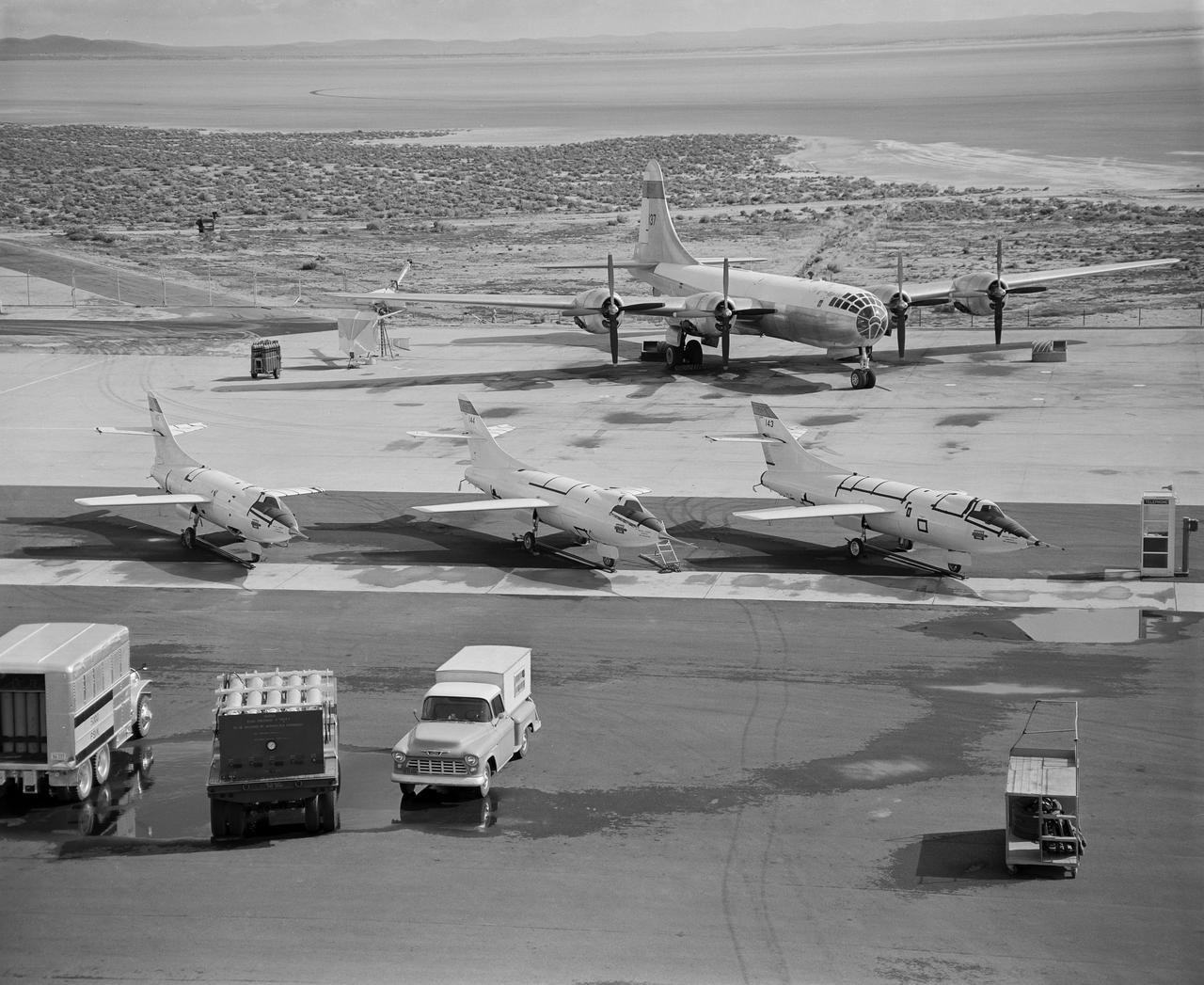
Behind three Douglas D-558-IIs is the B-29 launch aircraft. Under its right wing is the world’s first ground-based reaction control system motion simulator.

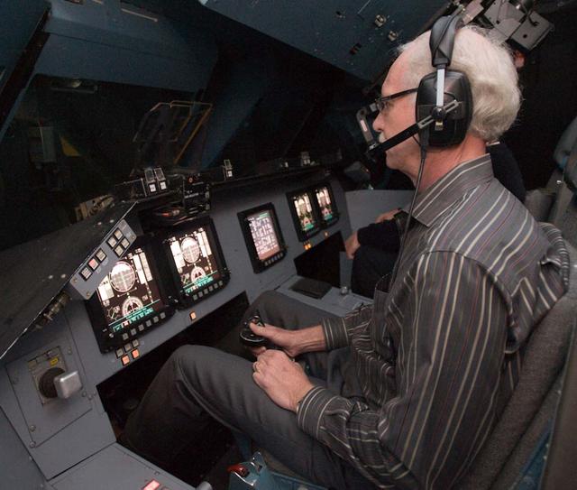
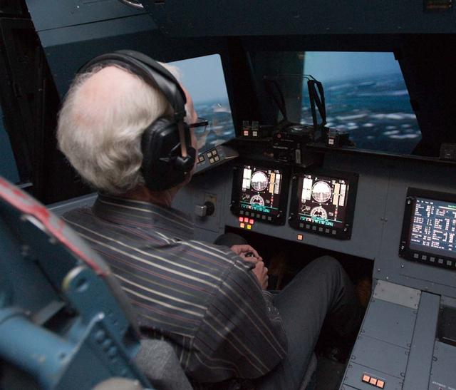
Out the window view of the ownship aircraft in the VMS’s R-Cab during the AVA-1h simulation in the VMS, N243.
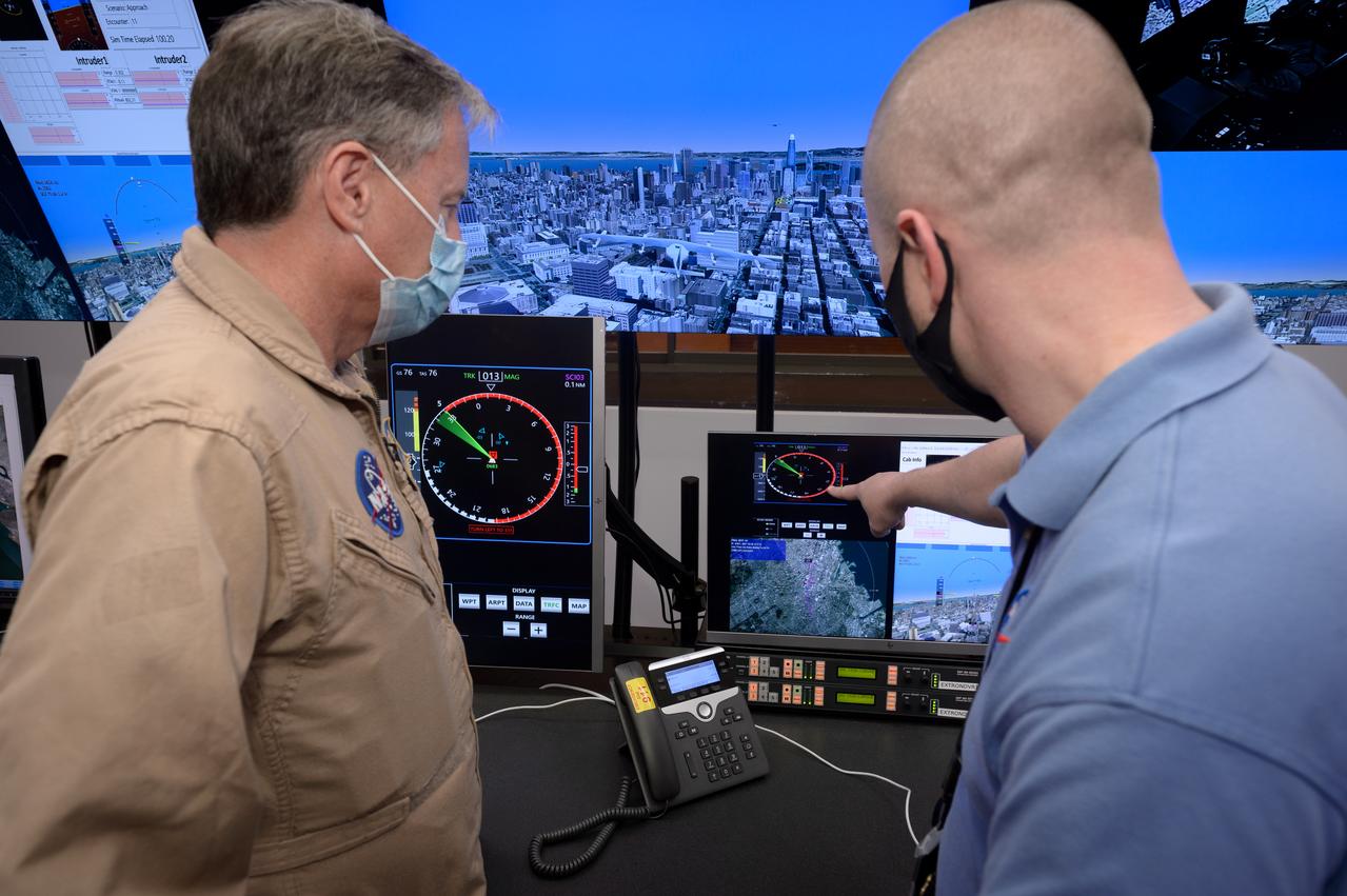
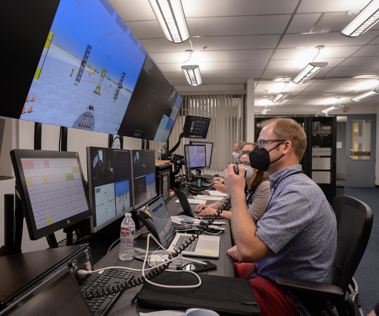
Human factors engineer Casey Smith, right, and pilot Wayne Ringelberg, left, discuss simulation results during a flight debrief in the VMS control room, N243.

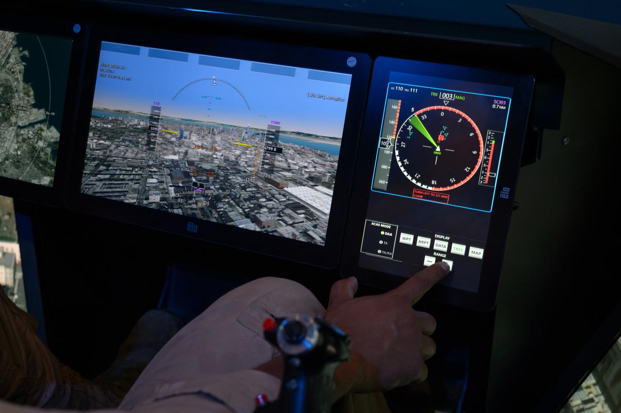
Pilot David Zahn fine-tunes the traffic display screen of the ownship aircraft in the VMS’s R-Cab during the AVA-1h simulation in the VMS, N243.

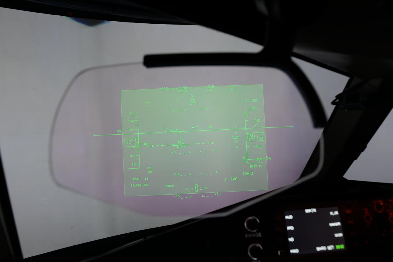
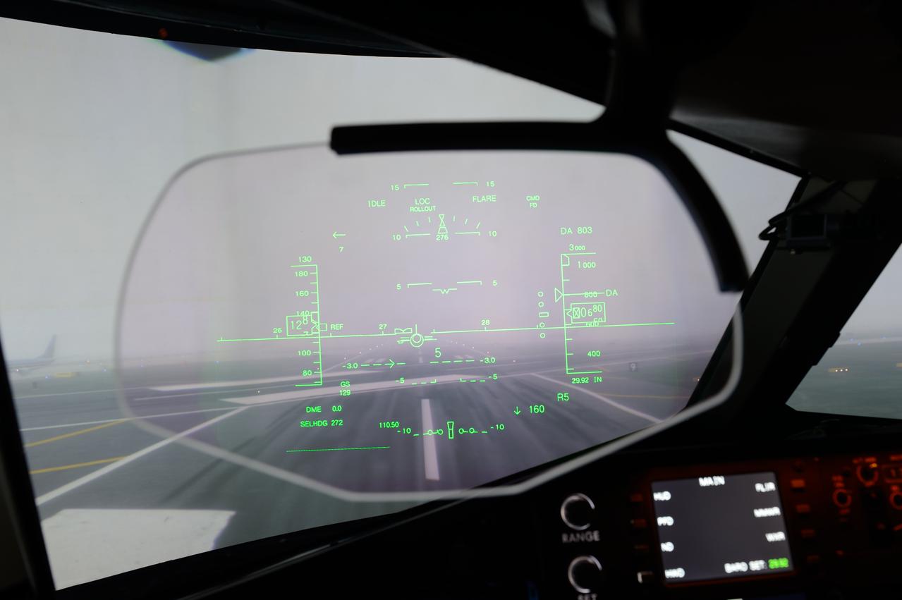
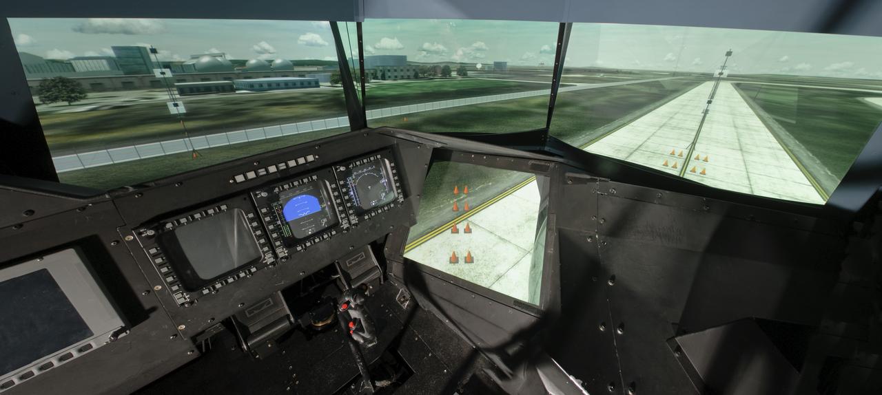
Traffic display screen of the ownship aircraft in the VMS’s R-Cab during the AVA-1h simulation in the VMS, N243.

Traffic display screen of the ownship aircraft in the VMS’s R-Cab during the AVA-1h simulation in the VMS, N243.

Human factors engineer Casey Smith, left, and pilot Wayne Ringelberg, right, discuss simulation results during a flight debrief in the VMS control room, N243.
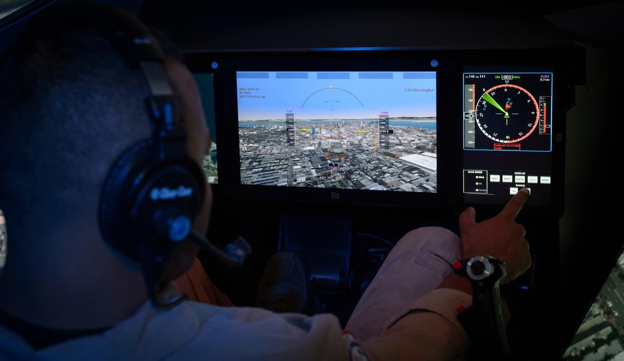
Pilot David Zahn fine-tunes the traffic display screen of the ownship aircraft in the VMS’s R-Cab during the AVA-1h simulation in the VMS, N243.
The development of the electric space actuator represents an unusual case of space technology transfer wherein the product was commercialized before it was used for the intended space purpose. MOOG, which supplies the thrust vector control hydraulic actuators for the Space Shuttle and brake actuators for the Space Orbiter, initiated development of electric actuators for aerospace and industrial use in the early 1980s. NASA used the technology to develop an electric replacement for the Space Shuttle main engine TVC actuator. An electric actuator is used to take passengers on a realistic flight to Jupiter at the US Space and Rocket Center, Huntsville, Alabama.

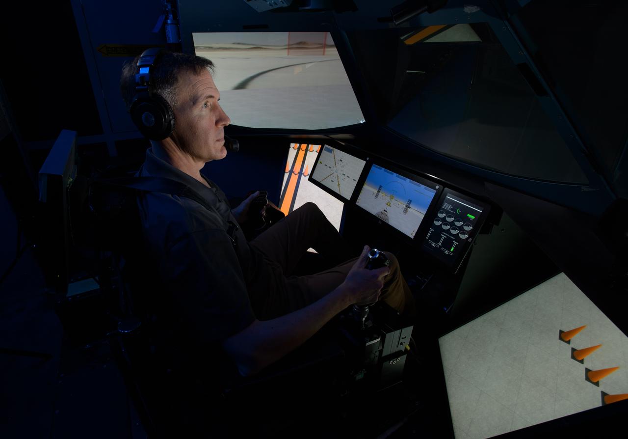
David Zahn pilots the ownship aircraft in the VMS’s R-Cab during the AVA-1h simulation in the VMS, N243.

Out the window view of the ownship aircraft in the VMS’s R-Cab during the AVA-1h simulation in the VMS, N243.

AVA-1h simulation team members Megan Mitchell, left, Christian Schmitz, and Matthew Blanken, right, in the VMS control room, N243, prepare for a simulation.

David Zahn pilots the ownship aircraft in the VMS’s R-Cab during the AVA-1h simulation in the VMS, N243.
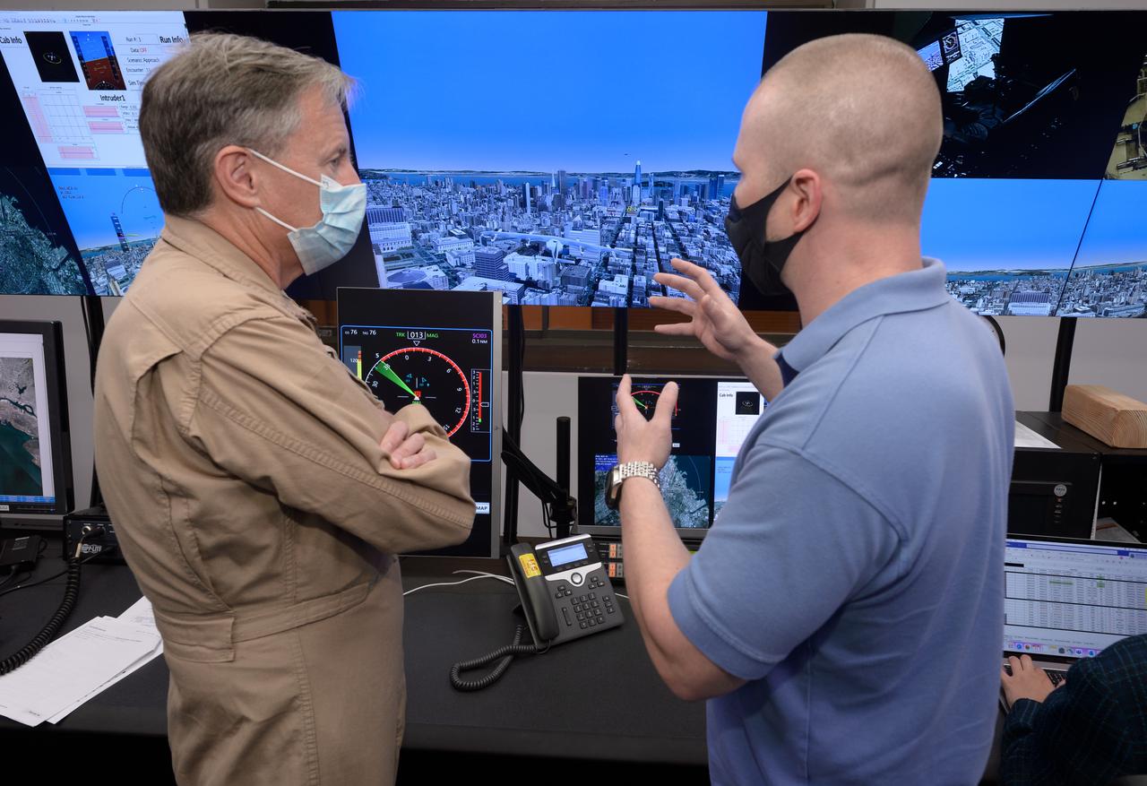
Human factors engineer Casey Smith, right, and pilot Wayne Ringelberg, left, discuss simulation results during a flight debrief in the VMS control room, N243.
Primary flight display screen, left, and traffic display screen, right, of the ownship aircraft in the VMS’s R-Cab during the AVA-1h simulation in the VMS, N243.

Human factors engineer Casey Smith, left, and pilot Wayne Ringelberg, right, discuss simulation results during a flight debrief in the VMS control room, N243.

Out the window view of the ownship aircraft in the VMS’s R-Cab during the AVA-1h simulation in the VMS, N243.

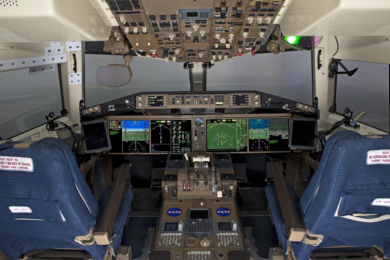
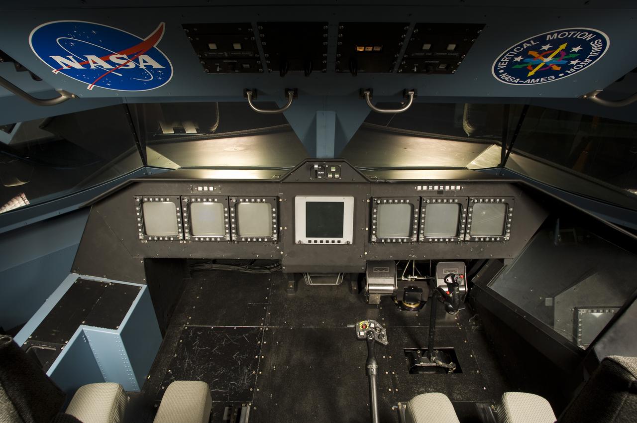
NASA Ames Vertical Motion Simulator (VMS)VMS (Vertical Motion Simulator) F-Cab interior. Overhead view of cockpit.
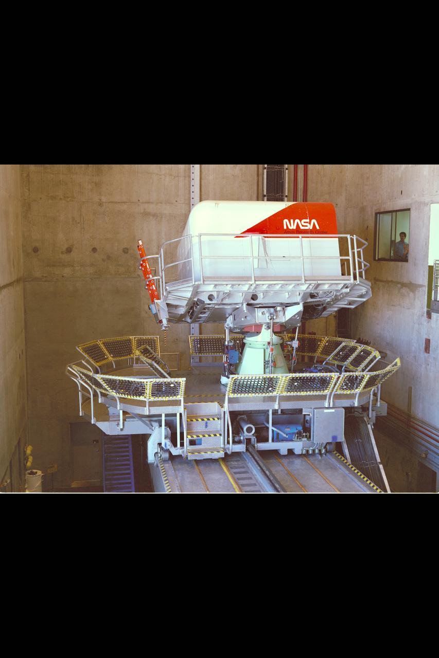
Ames 5 degrees-of-freedom motion simulator: This simulator incorporated a centrifuge of 30ft radius. The simulatored cockpit, located intn a hooded cab at the end of the centrifuge arm, was driven by motors, as required by the simulation, about each of its three axes (itch, roll, and yaw). The cab was also driven through a limited range of motion along the vertical axis and of course was driven by the centrifuge arm along a curved path of fixed radius in the horizontal plane. Thus the motions that could be simulated i the cab were three angular motions, one translational motion, and a curvilinear combination of the remaining two translational motions. The curvilinear motions, and associated accelerations, were, of course, fairly representative of airplane flight. The simulator was placed in operation early in 1961. ref: Adventures in Research (pg 341/341) NASA SP-4302
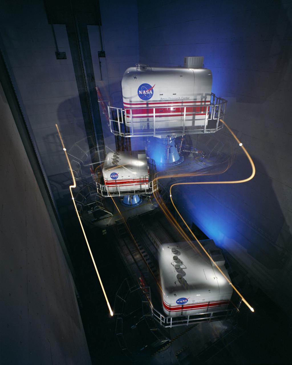
NASA Ames Bldg N-243A Vertical Motion Simulator cab in Motion in motion.
This moving base simulator was received in 1990 and is primarily a training and procedural trainer. It has been used in support of the SR-71 flight programs for many years.
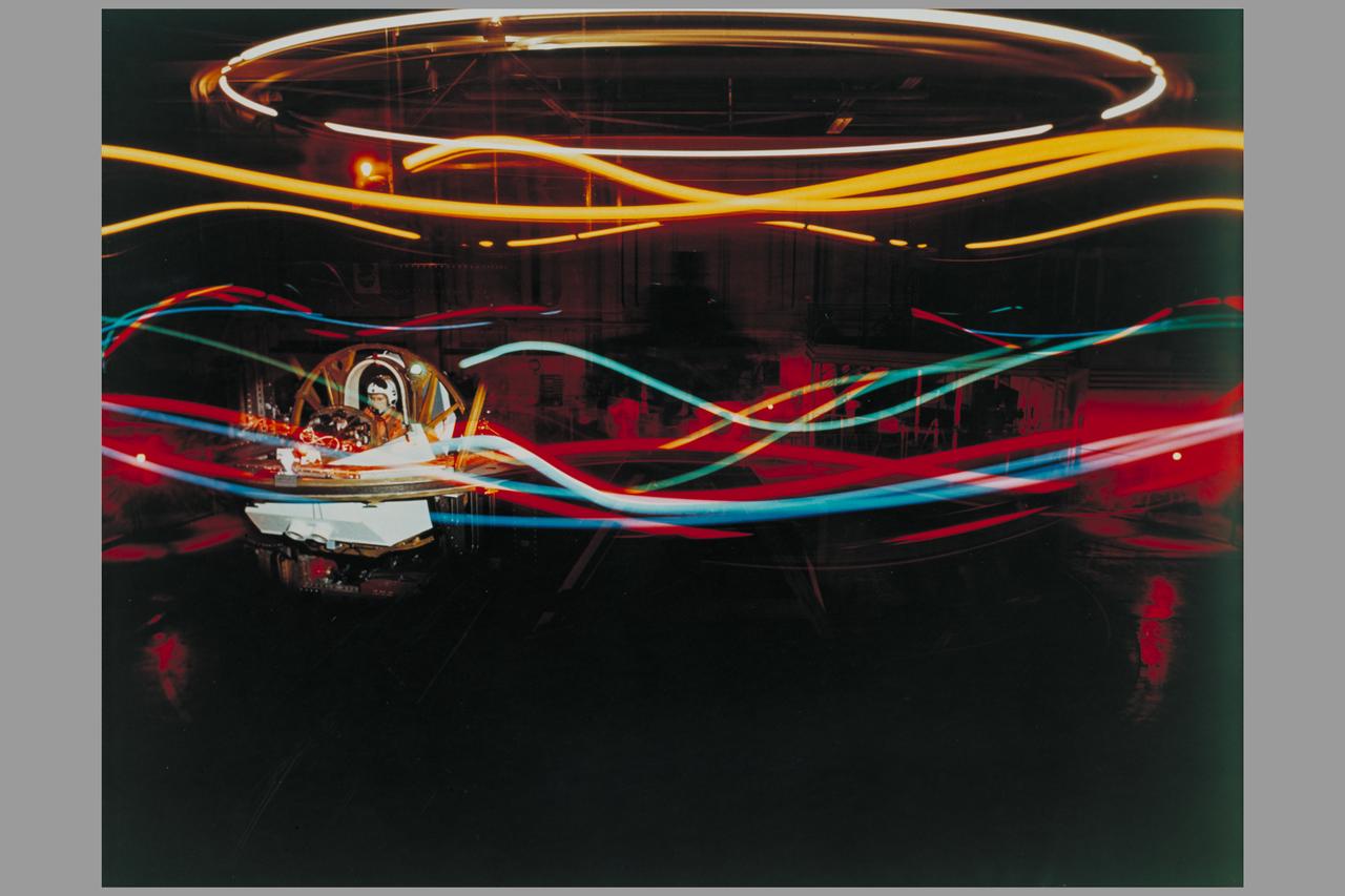
5 Degree Freedom of Motion Simulator with R. Gerdes (delayed exposure using lights to show motion)
N-243A Vertical Motion Simulator
N-243A Vertical Motion Simulator
N-243A Vertical Motion Simulator
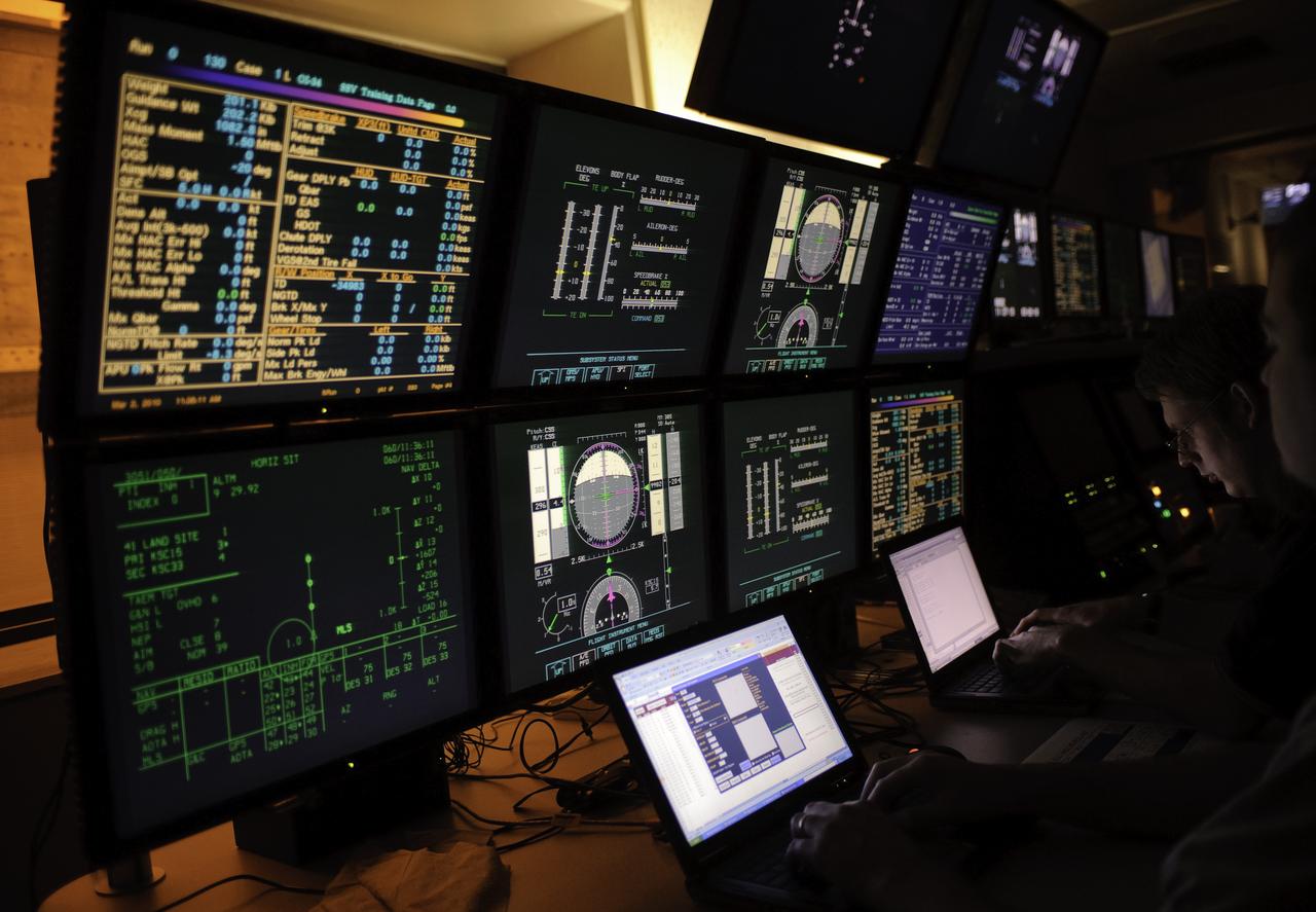
Vertical Motion Simulator (VMS) control room
Vertical Motion Simulator VMS Simulation; Rotorcraft Stability/Phase Margin in T-cab.
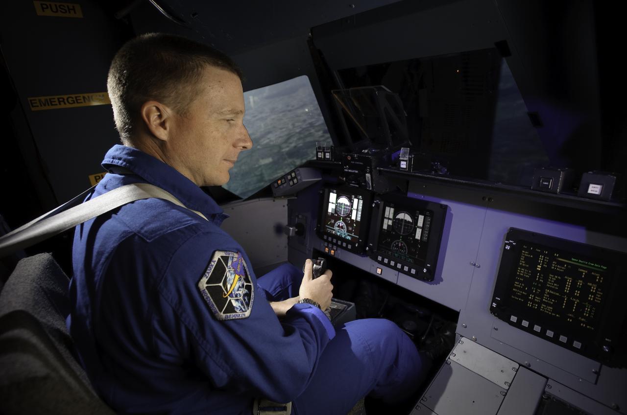
Vertical Motion Simulator (VMS) Astronaut Terry Virts flying the shuttle during simulation flight
AFCM subproject simulation FAA-2 flight test team members Thomas Lombaerts, left, and Kimberlee Shish, right, in the VMS control room, N243, during a simulation.
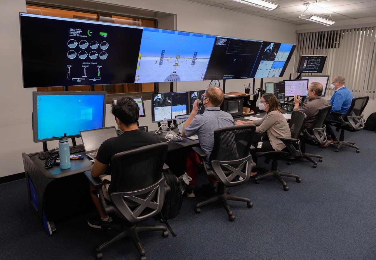
AFCM subproject simulation FAA-2 flight test team members Allen Ruan, left, Thomas Lombaerts, Kimberlee Shish, Edgar Torres, and Stephen Norris, right, in the VMS control room, N243 during a simulation.
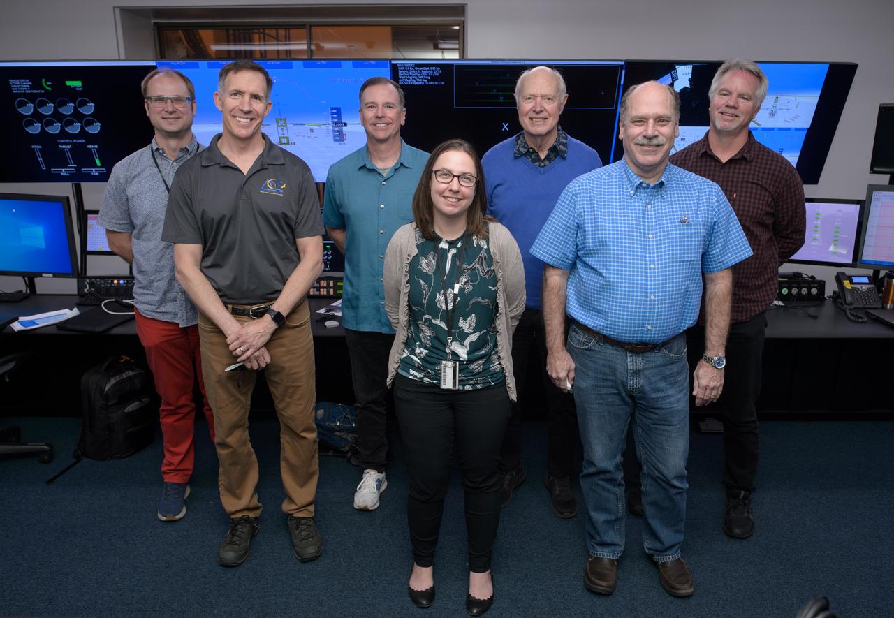
Group photo of AFCM subproject simulation FAA-2 flight test team members Thomas Lombaerts, left, Mike Feary, Dave Sizoo, Kimberlee Shish, Loran Haworth, Mitch Soth, and Dave Webber, right, in the VMS control room, N243.
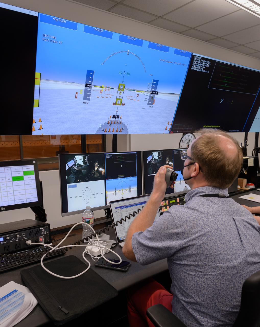
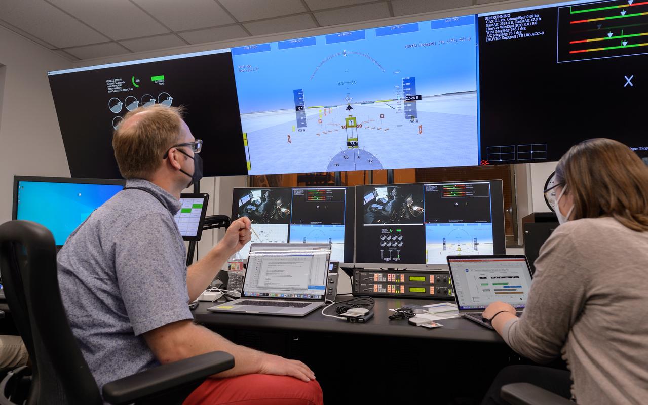
AFCM subproject simulation FAA-2 flight test team member Thomas Lombaerts in the VMS control room, N243, during a simulation.
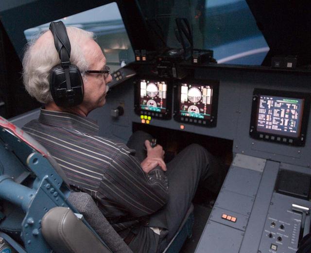
Michael Feary pilots a simulated electric vertical takeoff and landing, or eVTOL, aircraft in the VMS’s R-Cab during the AFCM subproject simulation FAA-2 flight tests in the VMS, N243.
AFCM subproject simulation FAA-2 flight test team member Thomas Lombaerts in the VMS control room, N243, during a simulation.
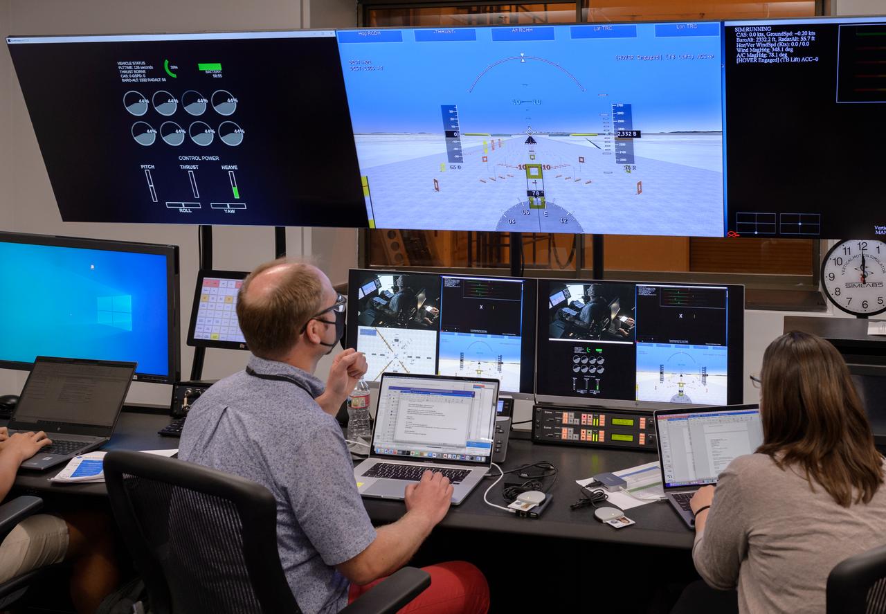
AFCM subproject simulation FAA-2 flight test team members Thomas Lombaerts, left, and Kimberlee Shish, right, in the VMS control room, N243, during a simulation.
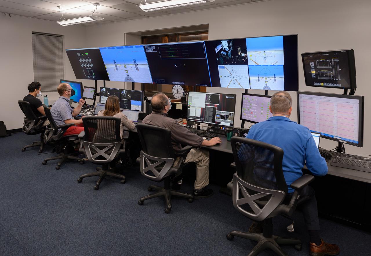
AFCM subproject simulation FAA-2 flight test team members Allen Ruan, left, Thomas Lombaerts, Kimberlee Shish, Edgar Torres, and Stephen Norris, right, in the VMS control room, N243 during a simulation.
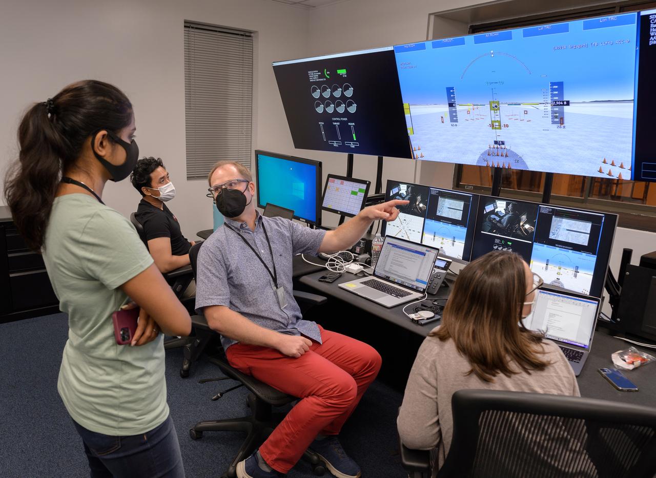
AFCM subproject simulation FAA-2 flight test team members Allen Ruan, left, Thomas Lombaerts, and Kimberlee Shish, right, in the VMS control room, N243, during a simulation.

AFCM subproject simulation FAA-2 flight test team members Allen Ruan, left, Thomas Lombaerts, and Kimberlee Shish, right, in the VMS control room, N243, during a simulation.
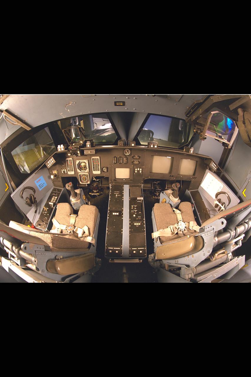
Ames Vertical Motion Simulator (VMS) T-Cab configuration
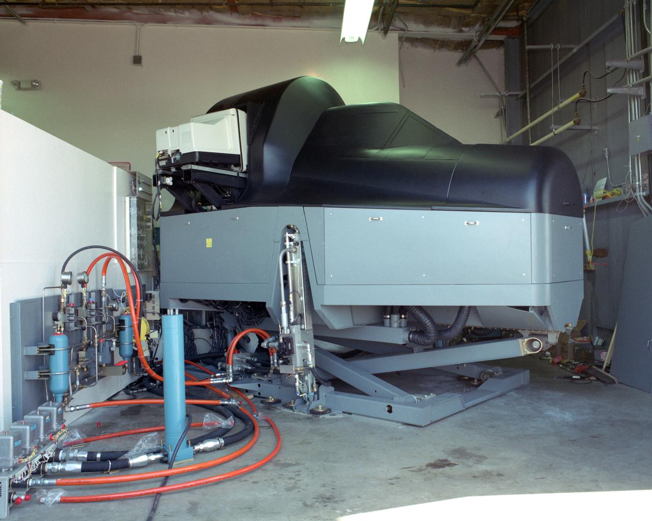
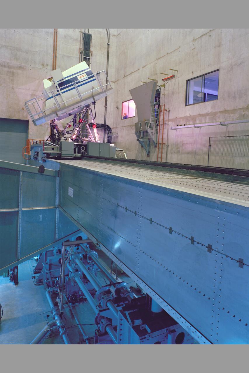
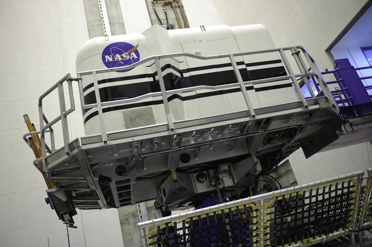
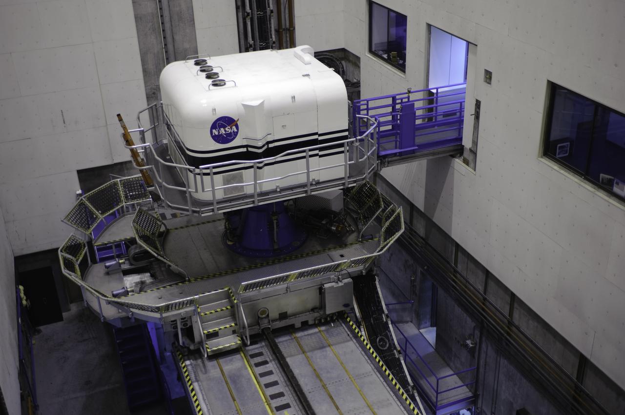
Vertical Motion Simulator (VMS) showing a Space Shuttle configuration
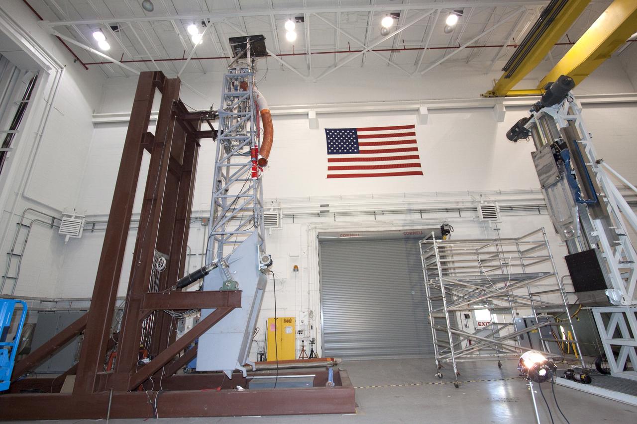
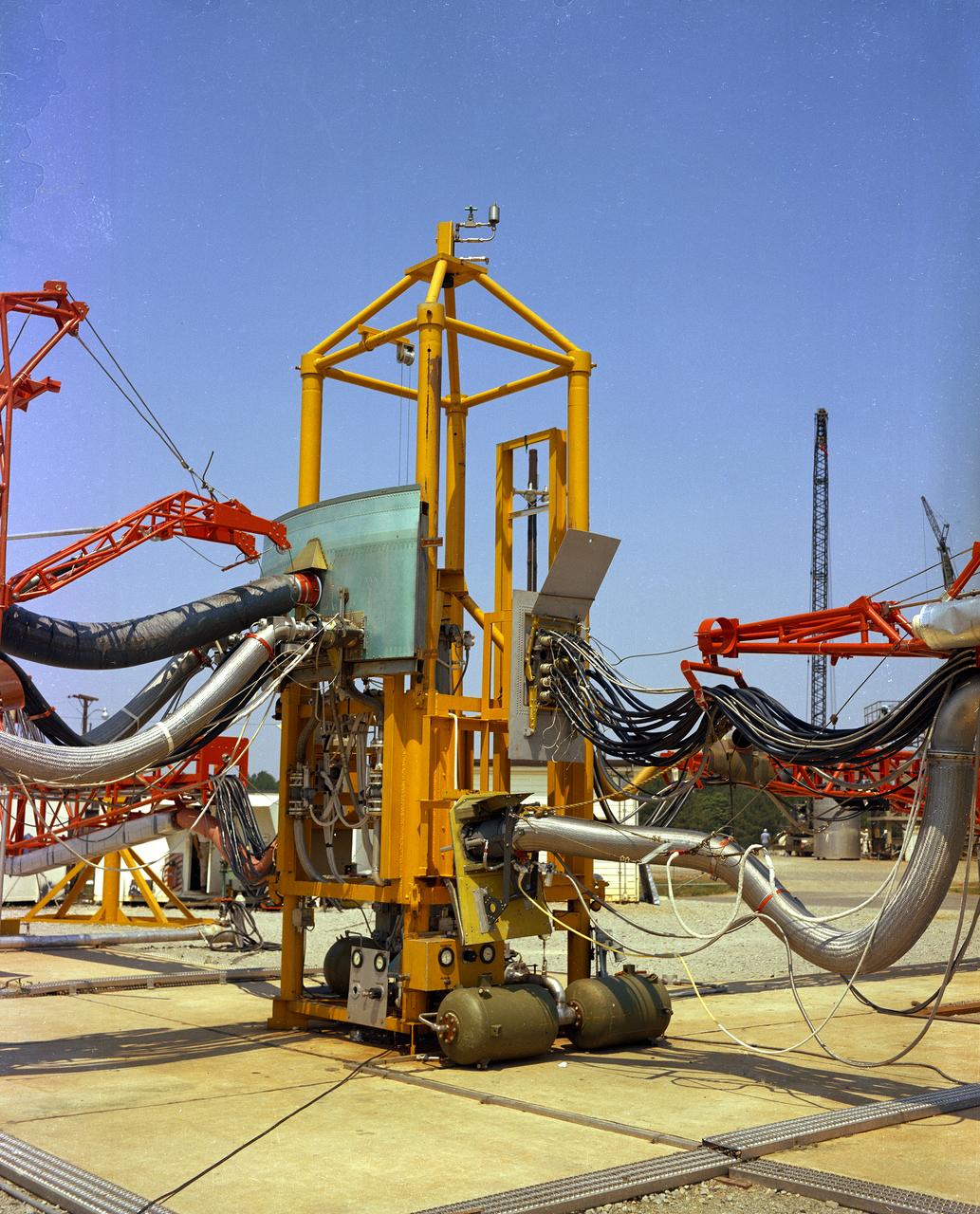
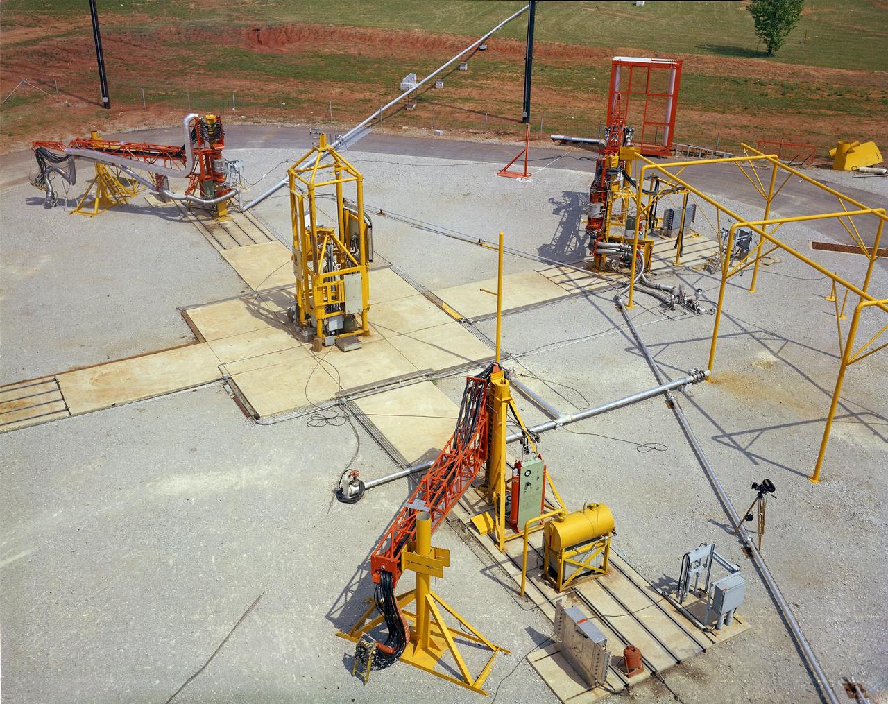
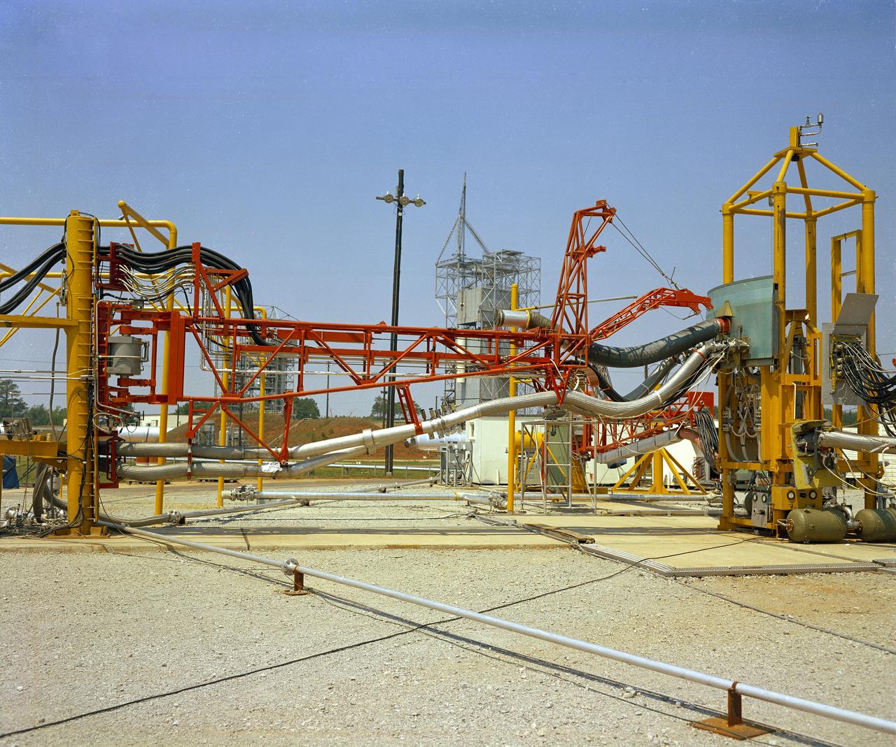
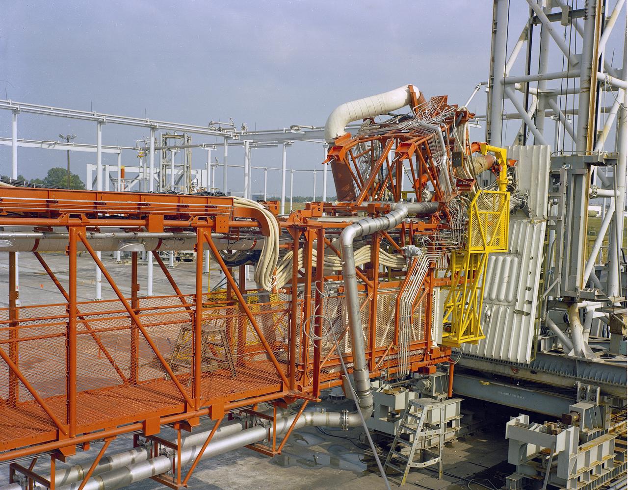
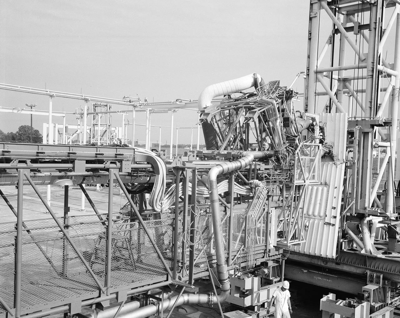
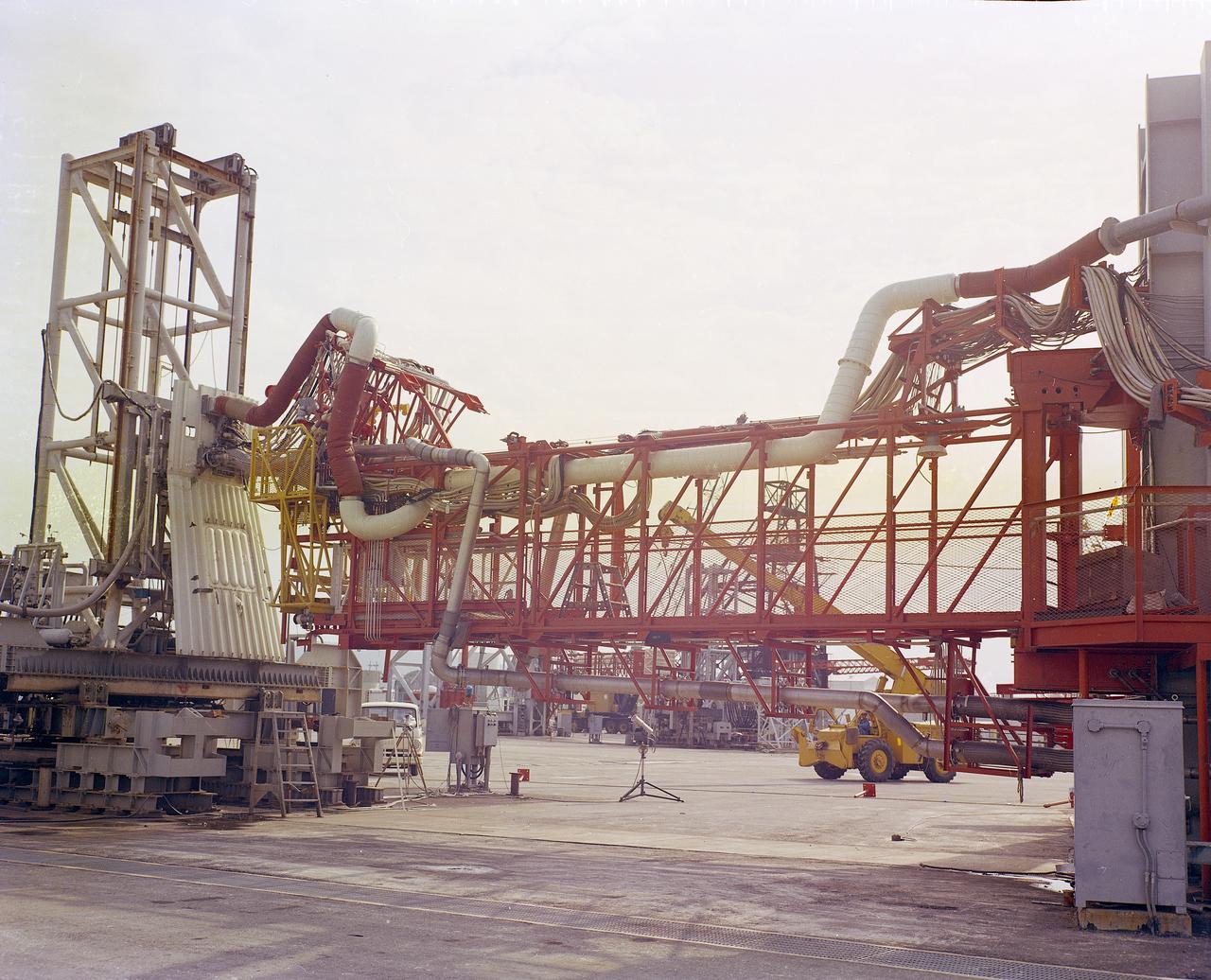
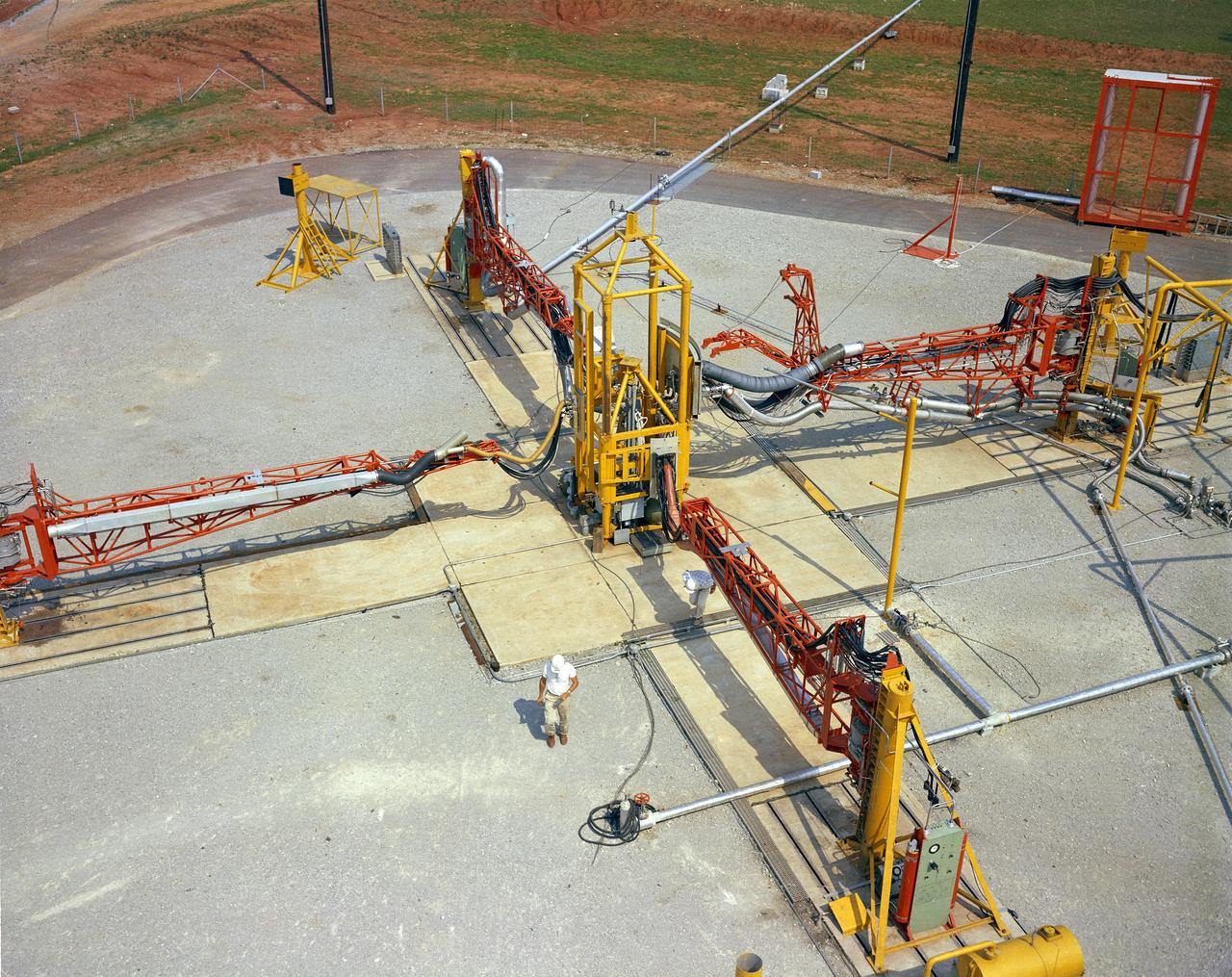
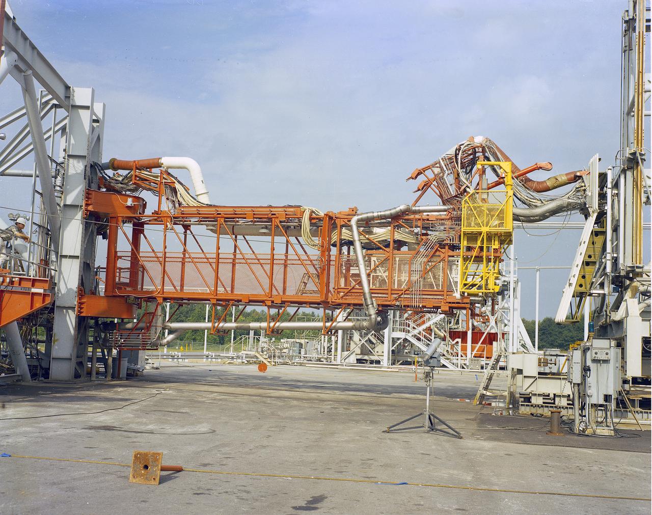
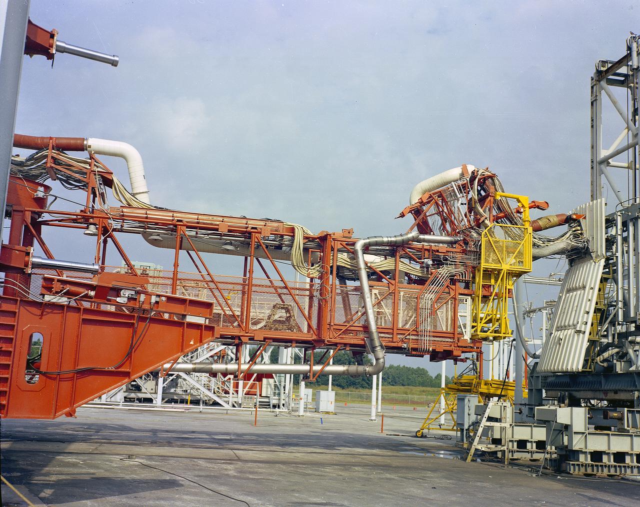
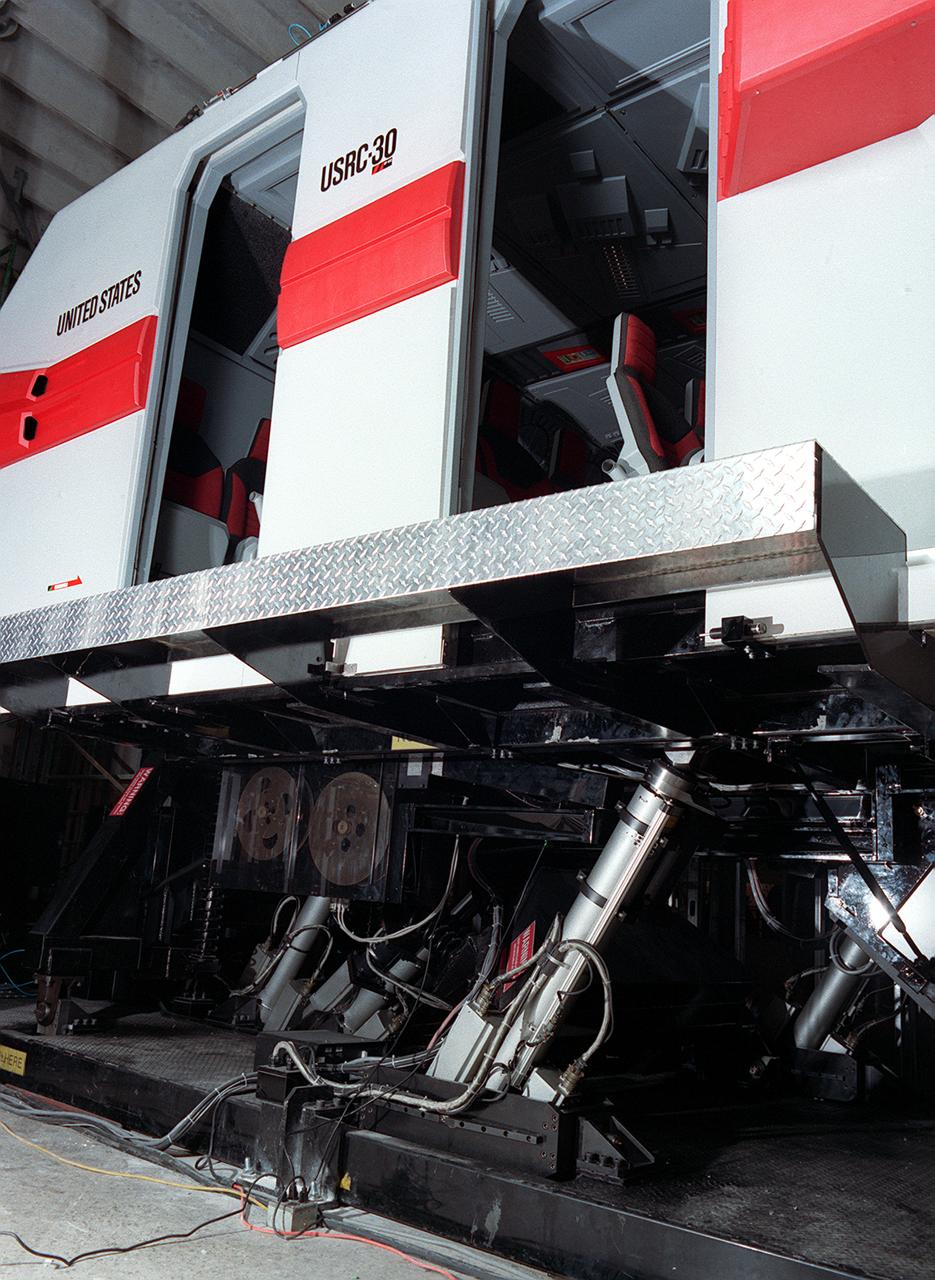
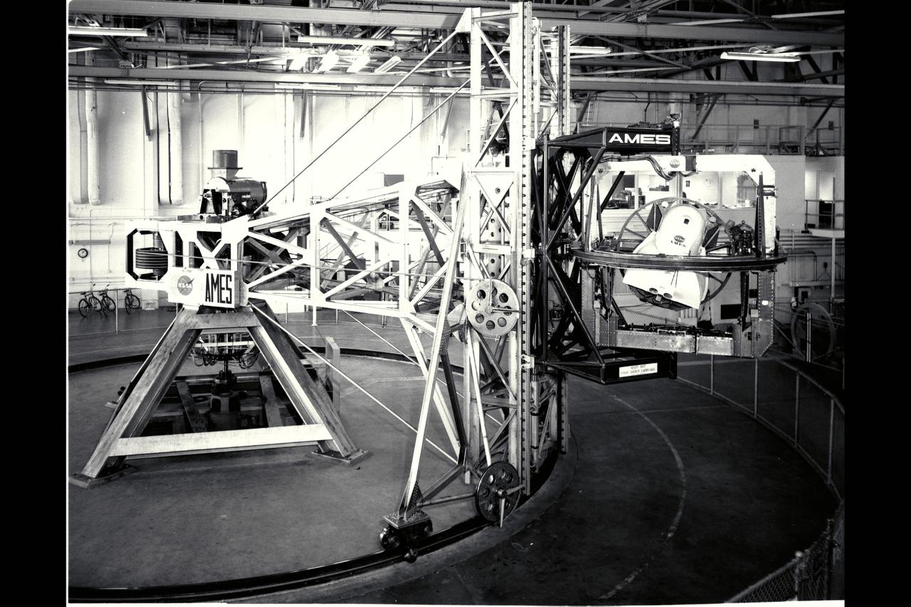
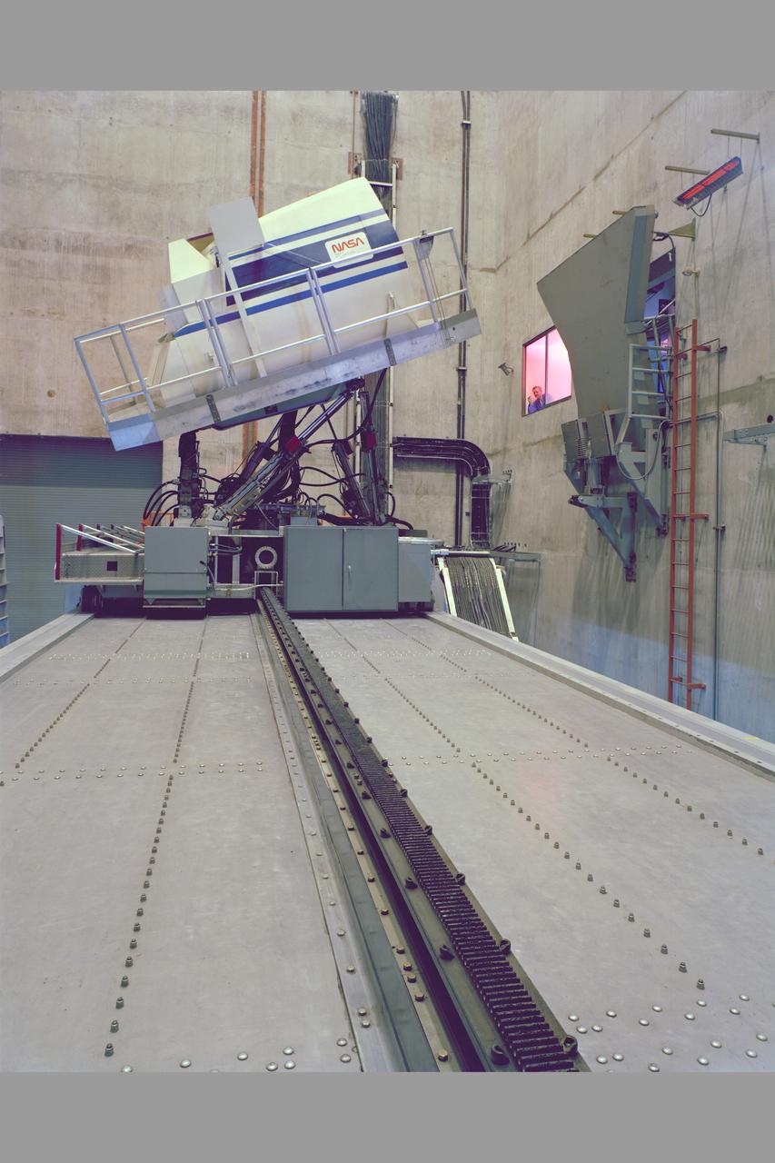
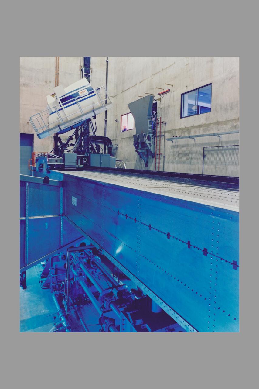
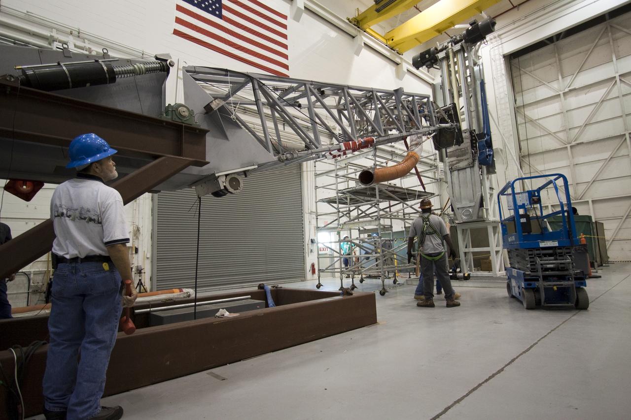
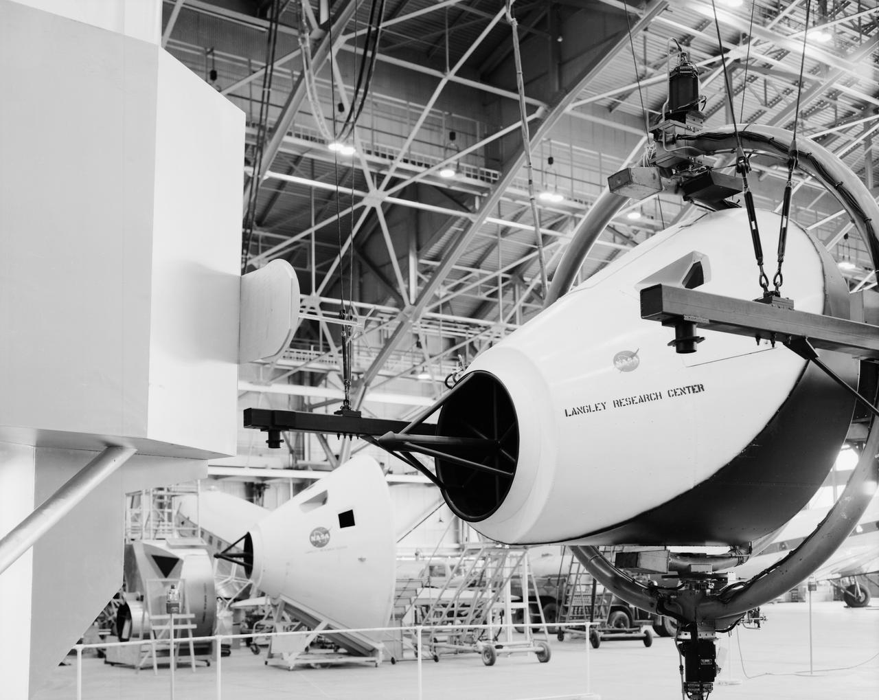
VEHICLE MOTION SIMULATOR (VMS) TILT-UP UMBILICAL ARM TESTING
Vertical Motion Simulator VMS-7600 Computer Lab in N-243.
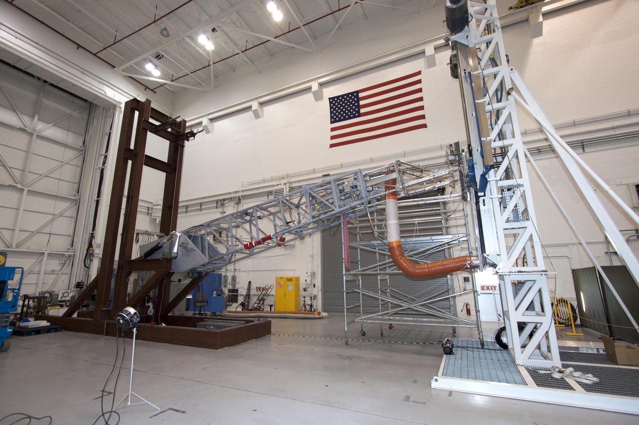
VEHICLE MOTION SIMULATOR (VMS) TILT-UP UMBILICAL ARM TESTING
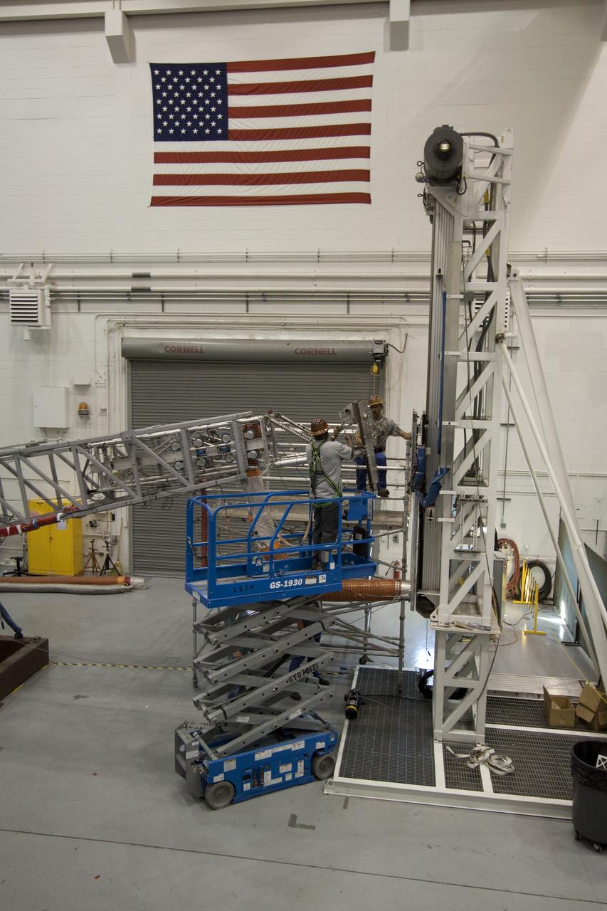
VEHICLE MOTION SIMULATOR (VMS) TILT-UP UMBILICAL ARM TESTING

N-234A: Exterior view of the VMS (Vertical Motion Simulator) T-cab
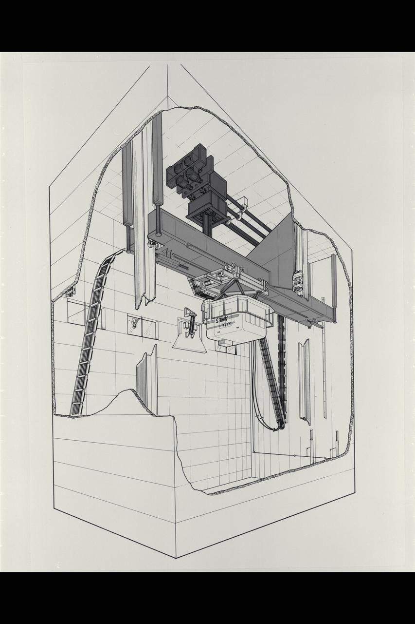
Illustration Vertical Motion Simulator (VMS) Facility and Cab cutaway
Vertical Motion Simulator (VMS) showing a Space Shuttle configuration
Ames Vertical Motion Simulator (VMS) T-Cab configuration
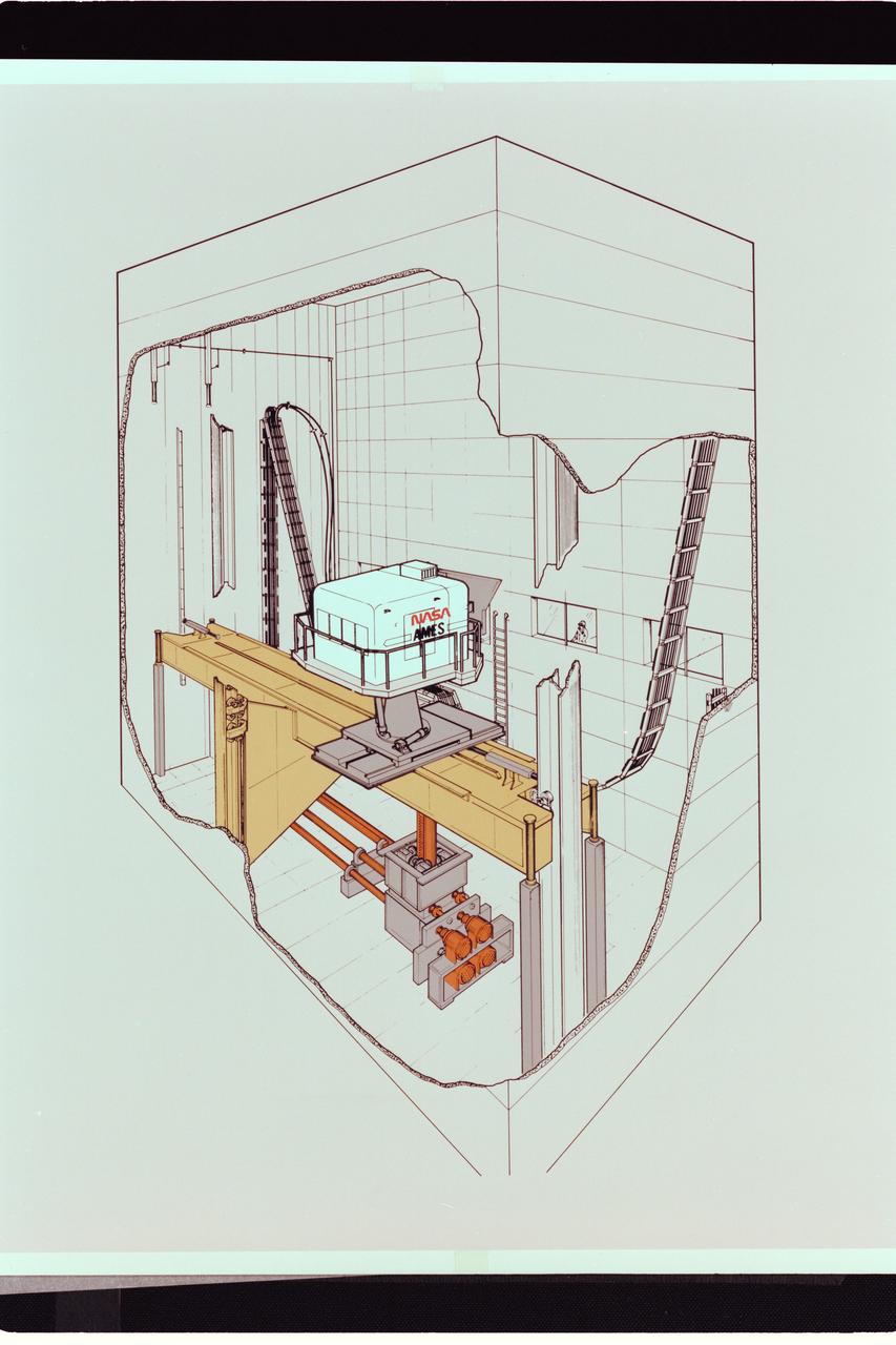
Artwork: cutaway N-243 Vertical Motion Simulator (VMS)
Ames Vertical Motion Simulator (VMS) T-Cab configuration
VEHICLE MOTION SIMULATOR (VMS) TILT-UP UMBILICAL ARM TESTING
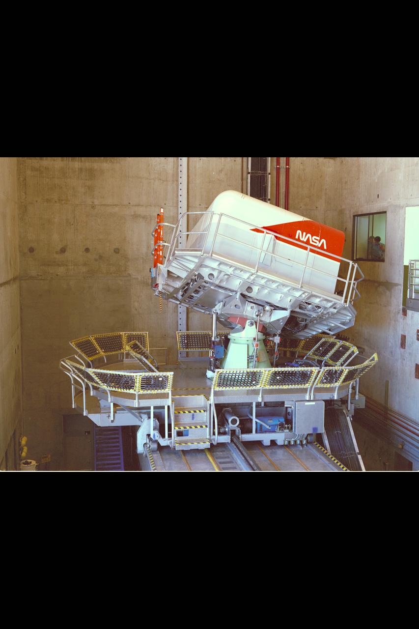
Vertical Motion Simulator (VMS) showing a Space Shuttle configuration
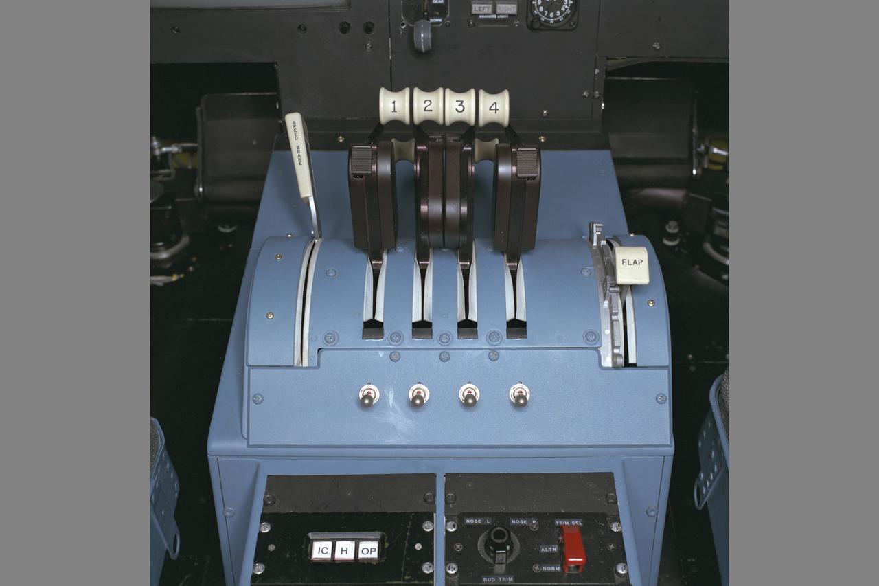
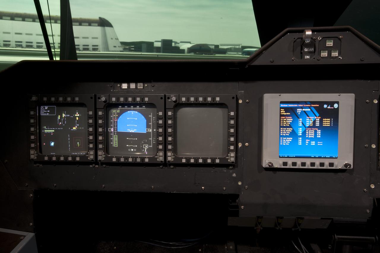
N-243 NASA Ames VMS (Vertical Motion simulator) S-Cab: HSCT (High Speed Civil Transport) Simulation Throttles
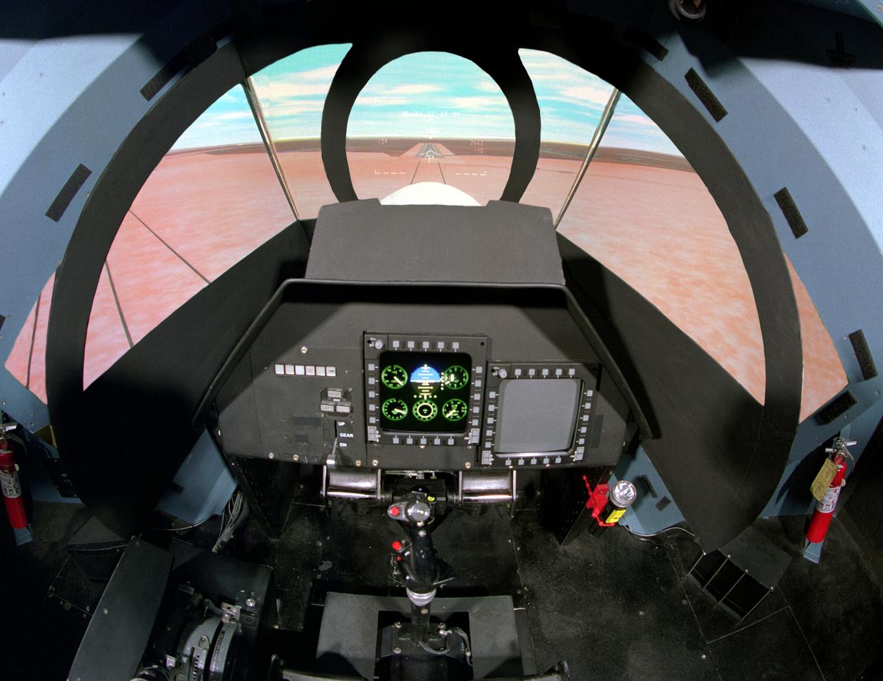
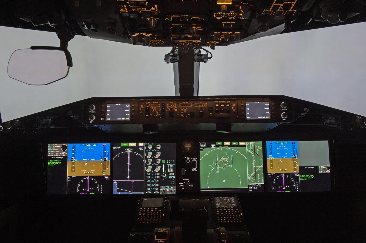
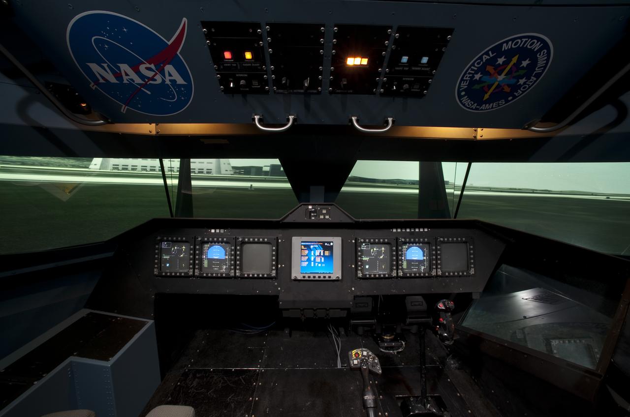
NASA Ames Vertical Motion Simulator (VMS): F-cab SIMFR (Simulation Frequency Response) Project; Pilots cockpit and out-the-window (OTW) view
Vertical Motion Simulator VMS Simulation; Rotorcraft Stability/Phase Margin in T-cab. out the window panorama - overall cab view
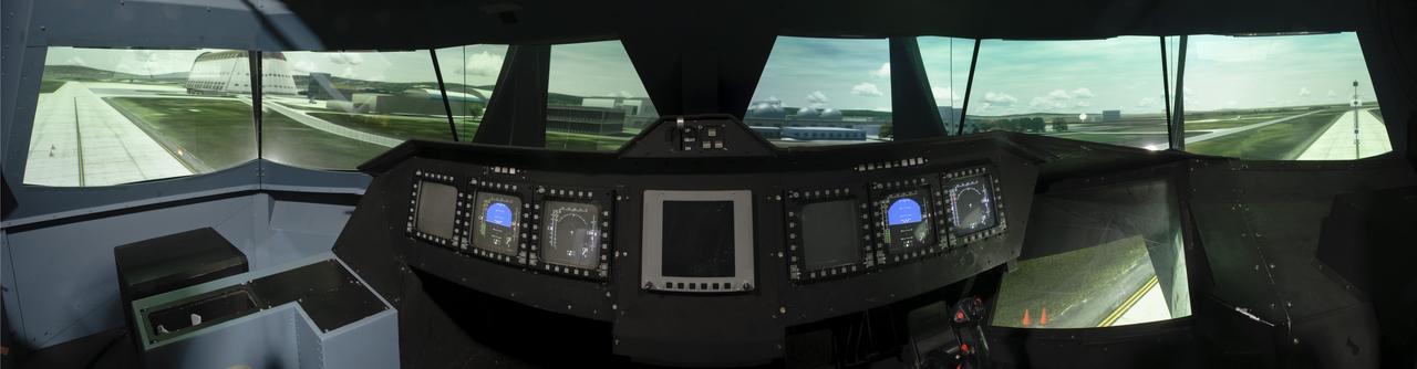
Vertical Motion Simulator VMS Simulation; Rotorcraft Stability/Phase Margin in T-cab. Out-the-window (otw) panorama views from pilots point of view
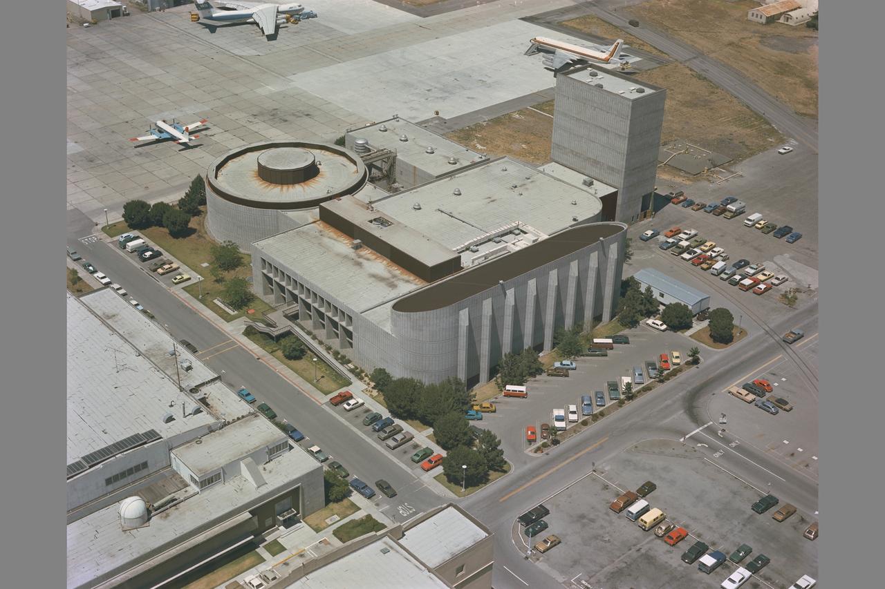
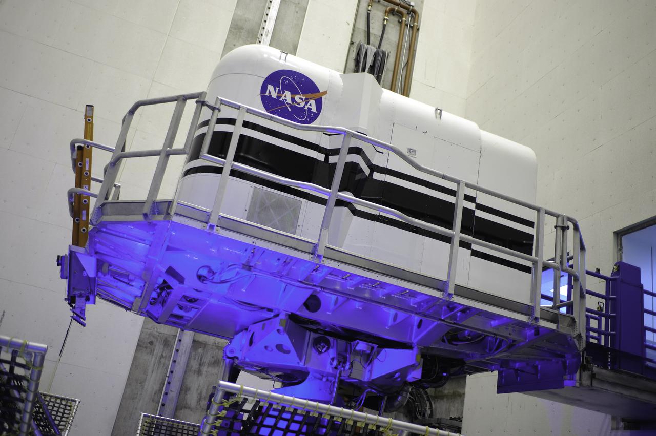
Aerial of Ames: N-243 (Flight and Guidance Simulation Laboratory) and N-243A (Simulation Equipment) houses the Vertical Motion Simulator (VMS) and the Crew Station Research Development Facility (CSRDF)
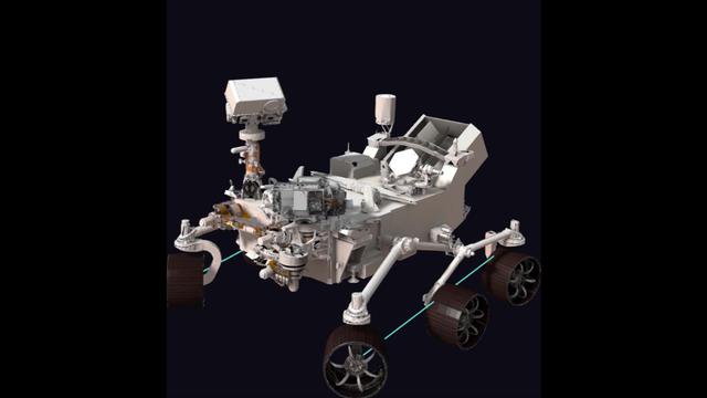
This simulation shows the motions the robotic arm on NASA's Perseverance rover carried out during its first two-hour checkout since its Feb. 18, 2021 touchdown on Mars. This simulation does not run in real-time. A key objective for Perseverance's mission on Mars is astrobiology, including the search for signs of ancient microbial life. The rover will characterize the planet's geology and past climate, pave the way for human exploration of the Red Planet, and be the first mission to collect and cache Martian rock and regolith (broken rock and dust). Subsequent NASA missions, in cooperation with ESA (European Space Agency), would send spacecraft to Mars to collect these sealed samples from the surface and return them to Earth for in-depth analysis. The Mars 2020 Perseverance mission is part of NASA's Moon to Mars exploration approach, which includes Artemis missions to the Moon that will help prepare for human exploration of the Red Planet. Animation available at https://photojournal.jpl.nasa.gov/catalog/PIA24332
Originally the Rendezvous was used by the astronauts preparing for Gemini missions. The Rendezvous Docking Simulator was then modified and used to develop docking techniques for the Apollo program. This picture shows a later configuration of the Apollo docking with the LEM target. A.W. Vogeley described the simulator as follows: The Rendezvous Docking Simulator and also the Lunar Landing Research Facility are both rather large moving-base simulators. It should be noted, however, that neither was built primarily because of its motion characteristics. The main reason they were built was to provide a realistic visual scene. A secondary reason was that they would provide correct angular motion cues (important in control of vehicle short-period motions) even though the linear acceleration cues would be incorrect. -- Published in A.W. Vogeley, Piloted Space-Flight Simulation at Langley Research Center, Paper presented at the American Society of Mechanical Engineers, 1966 Winter Meeting, New York, NY, November 27 - December 1, 1966.
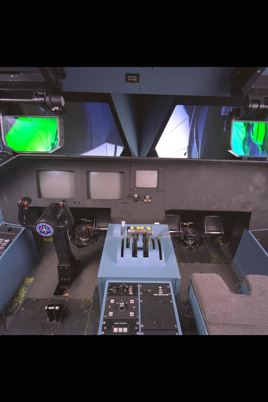
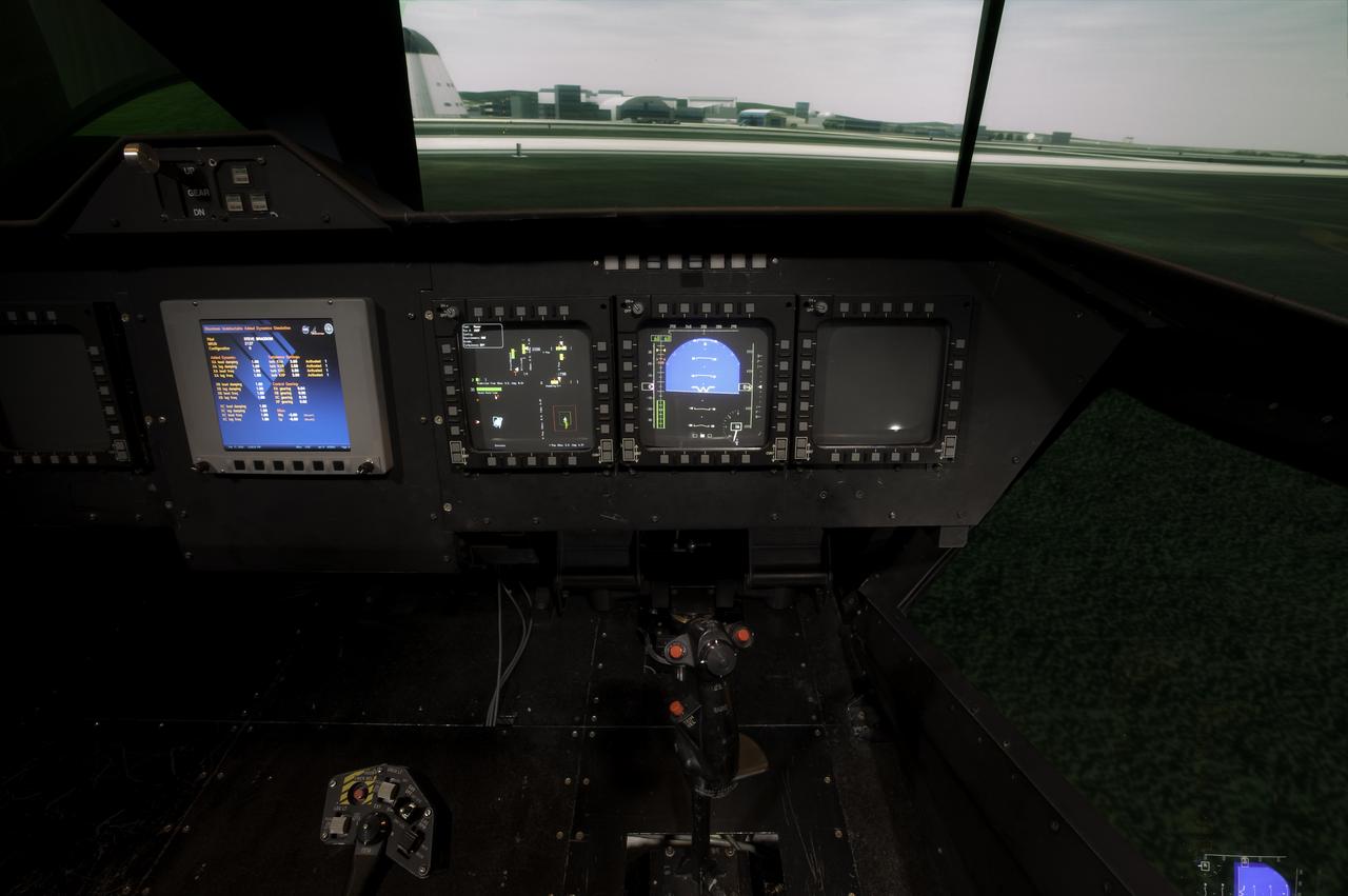
NASA Ames VMS (Vertical Motion simulator) S-Cab: Cockpit, Control Panel and heads-up displays
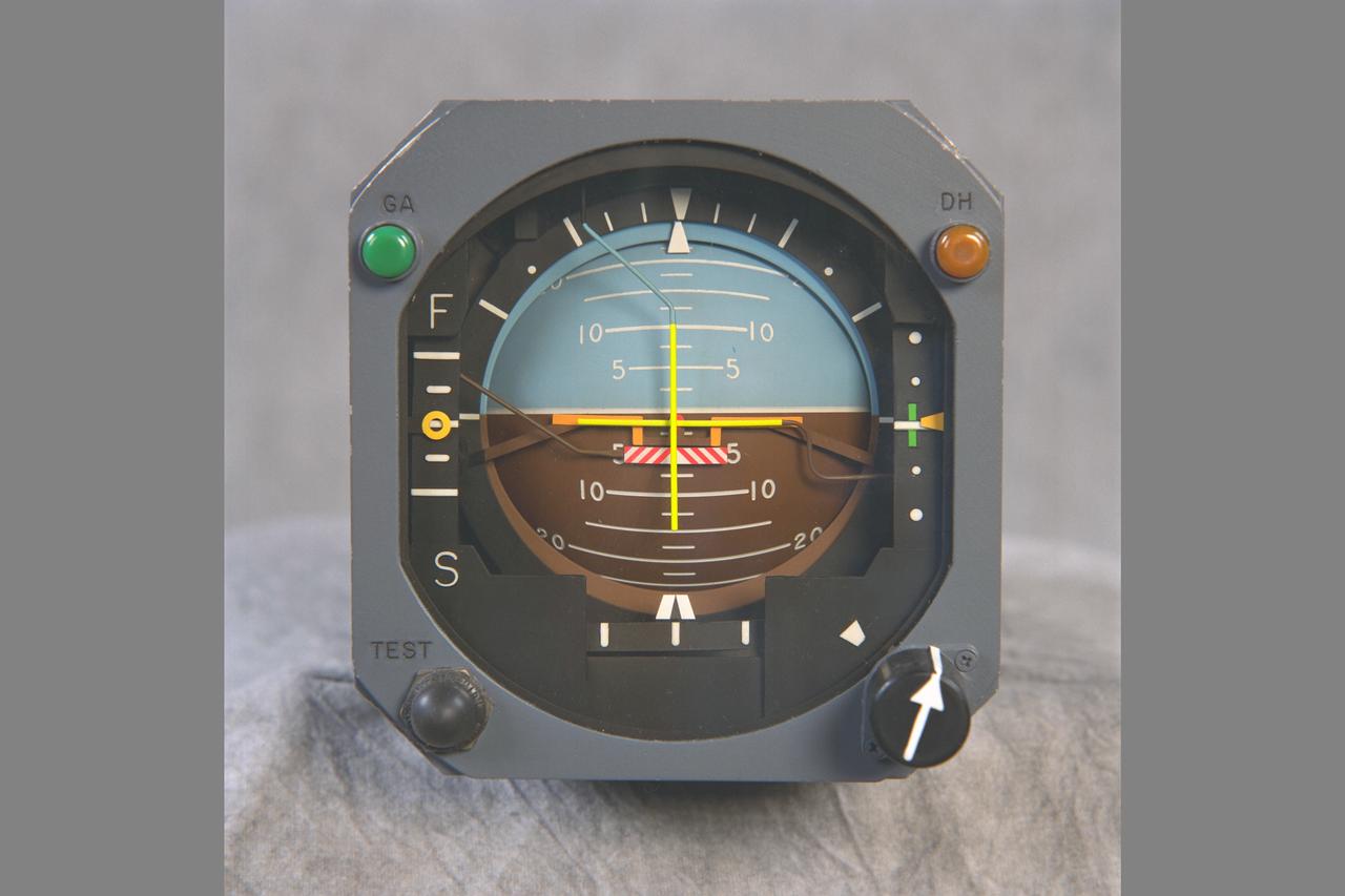
ARTIFICIAL HORIZON gage used in the NASA Ames VMS: S-CAB, (Vertical Motion Simulator).
Capt. Chesley 'Sully' Sullenberger visits Ames Vertical Motion Simulator facility and takes a 'ride' in the Shuttle Cab (S-cab).

Capt. Chesley 'Sully' Sullenberger visits Ames Vertical Motion Simulator facility and takes a 'ride' in the Shuttle Cab (S-cab).
Capt. Chesley 'Sully' Sullenberger visits Ames Vertical Motion Simulator facility and takes a 'ride' in the Shuttle Cab (S-cab).
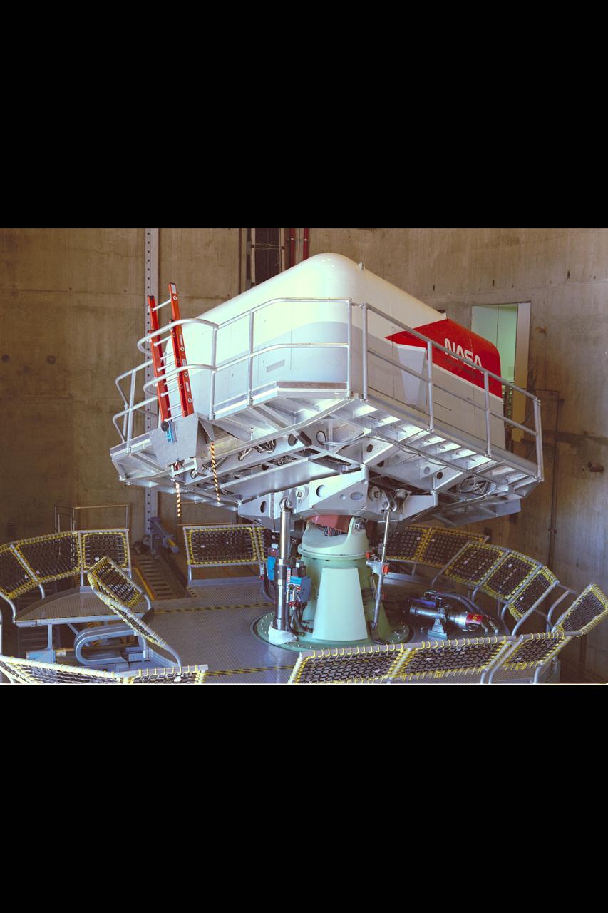
Vertical Motion Simulator (VMS) interior with Shuttle Cab (S-cab) mounted in facility.
Capt. Chesley 'Sully' Sullenberger visits Ames Vertical Motion Simulator facility and takes a 'ride' in the Shuttle Cab (S-cab).
NASA Ames VMS (Vertical Motion Simulator): S-CAB, THROTTLE CONSOLE studio shoot
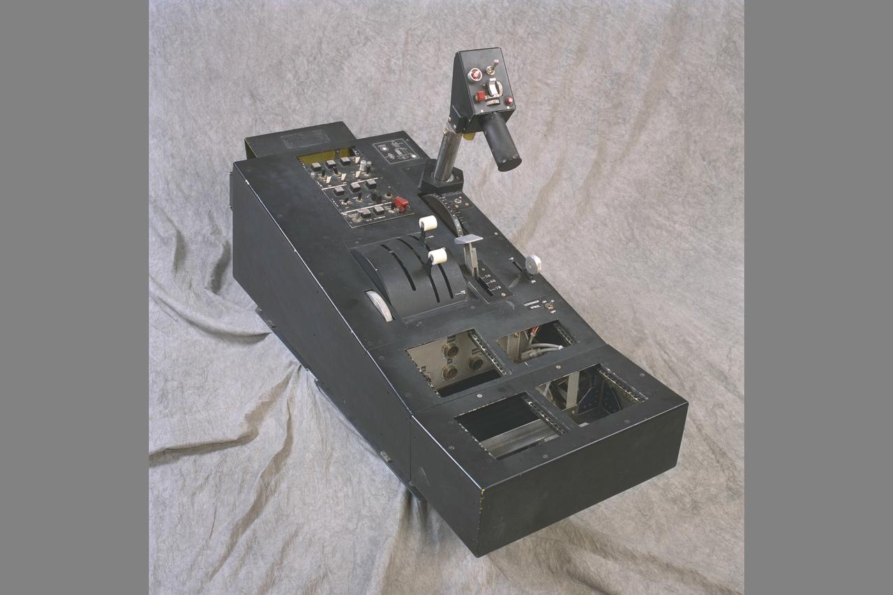
ROTOCRAFT CONSOLE. NASA Ames VMS: S-CAB, (Vertical Motion Simulator). studio shot
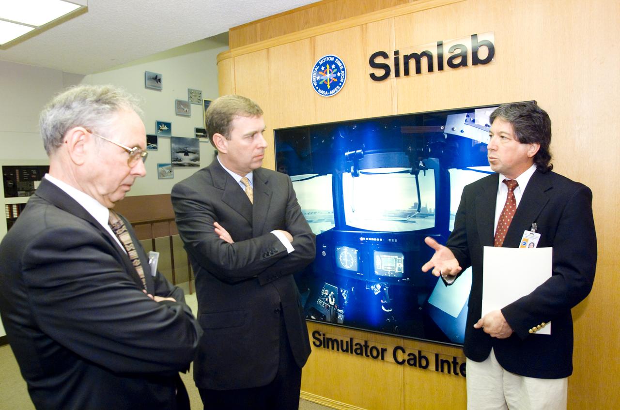
British royalty visits Ames; Prince Andrew, Duke of York on tour of Vertical Motion Simulator Facilities (VMS)
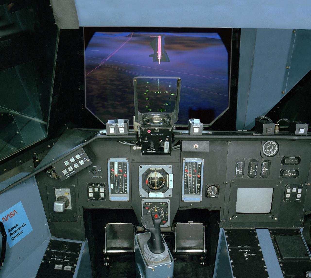
NASA Ames VMS (Vertical Motion simulator) S-cab Space Shuttle sim with out the window views 'night landing'
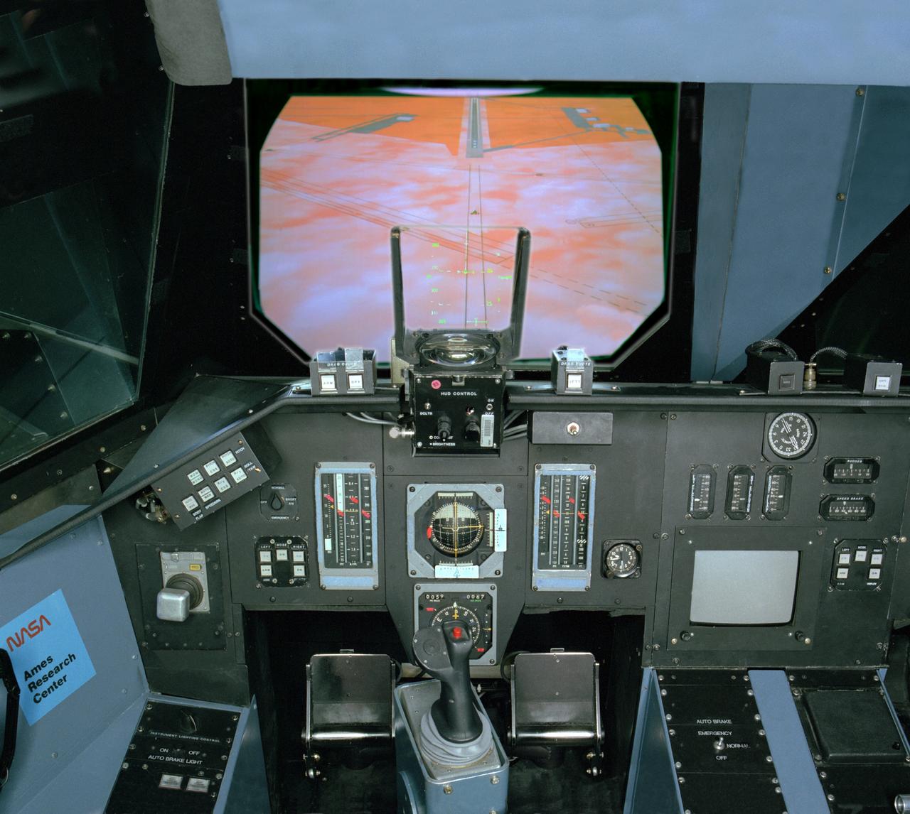
NASA Ames VMS (Vertical Motion simulator) S-cab Space Shuttle sim with out the window views 'DFRC landing'
NASA Ames Vertical Motion Simulator (VMS); T-Cab Civil Tilt Rotor Project (CTR) project cab configuration
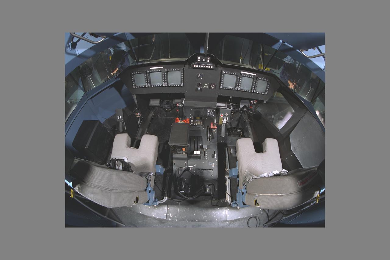
NASA Ames VMS (Vertical Motion Simulator) S-Cab (Space Shuttle Cab) overhead fisheye view

N-210 Flight Systems Research Laboratory, pre-design renolvation project - dismatelling of 6 degree freedom of motion simulator
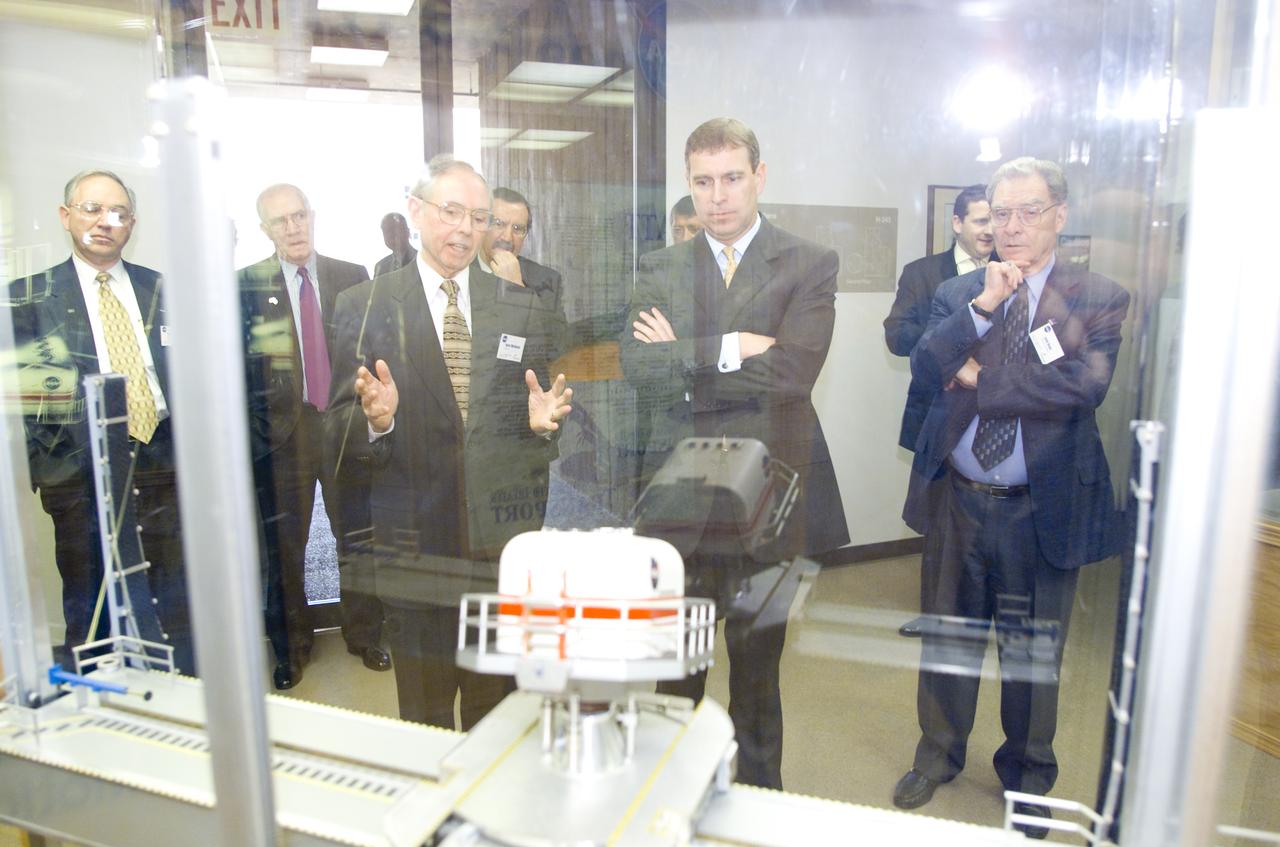
British royalty visits Ames; Prince Andrew, Duke of York on tour at the VMS (Vertical Motion Simulator)
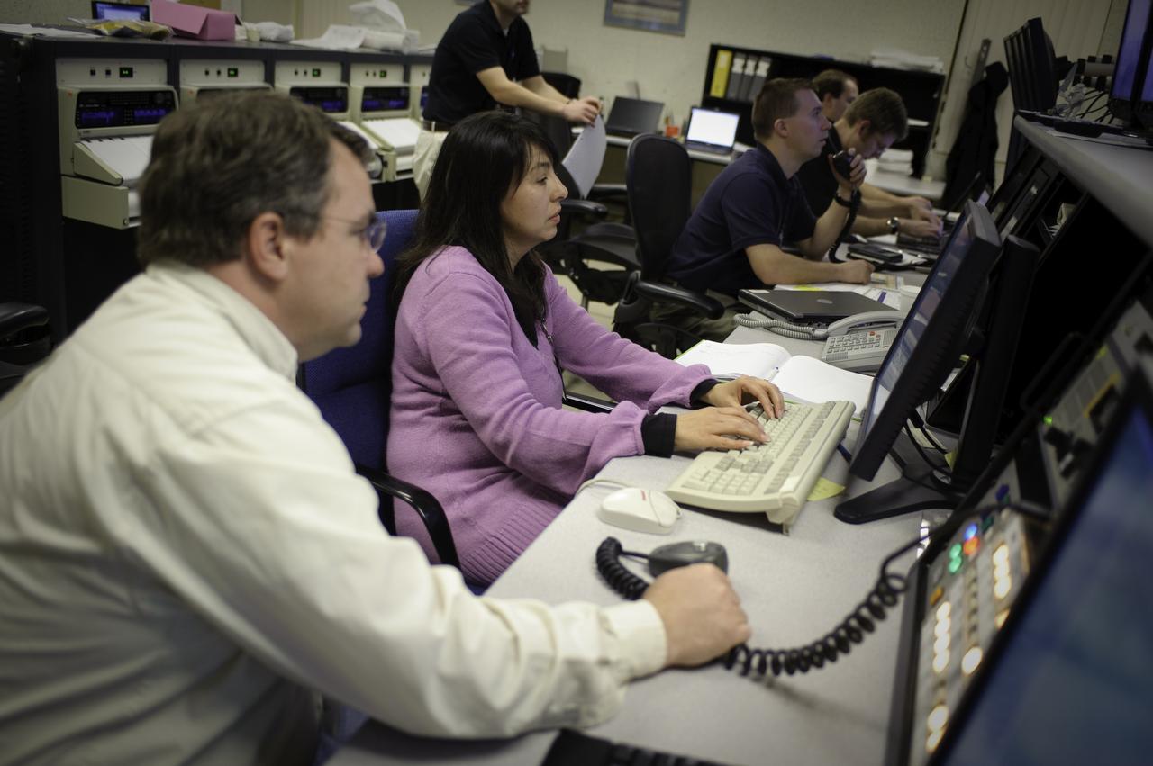
Vertical Motion Simulator (VMS) control room with Steve Beard and Estela Hernandez-Buchmann

Six degree motion simulator, S.01 chair with V. Merrick at the Ames Research Center, Moffett Field, CA
Vertical Motion Simulator (VMS) interior with Shuttle Cab (S-cab) mounted in facility.
Vertical Motion Simulator (VMS) interior with Shuttle Cab (S-cab) mounted in facility.