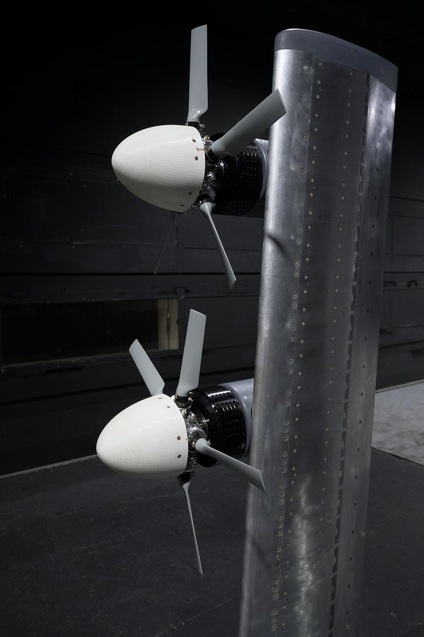
In May and June, NASA researchers tested a 7-foot wing model in the 14-by-22-Foot Subsonic Wind Tunnel at NASA’s Langley Research Center in Hampton, Virginia. The team collected data on critical propeller-wing interactions over the course of several weeks

NASA employees Broderic J. Gonzalez, left, and David W. Shank, right, install pieces of a 7-foot wing model in preparation for testing in the 14-by-22-Foot Subsonic Wind Tunnel at NASA's Langley Research Center in Hampton, Virginia, in May 2025. The lessons learned from this testing will be shared with the public to support advanced air mobility aircraft development.
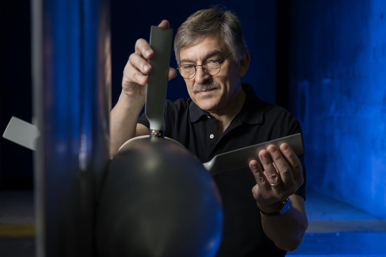
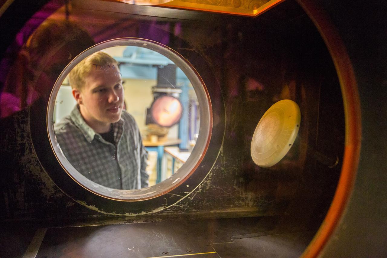
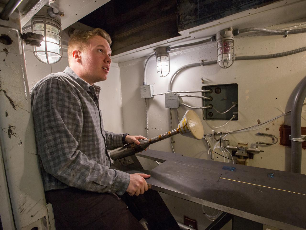
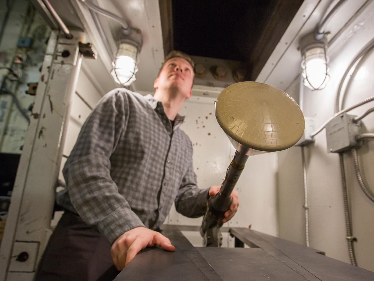
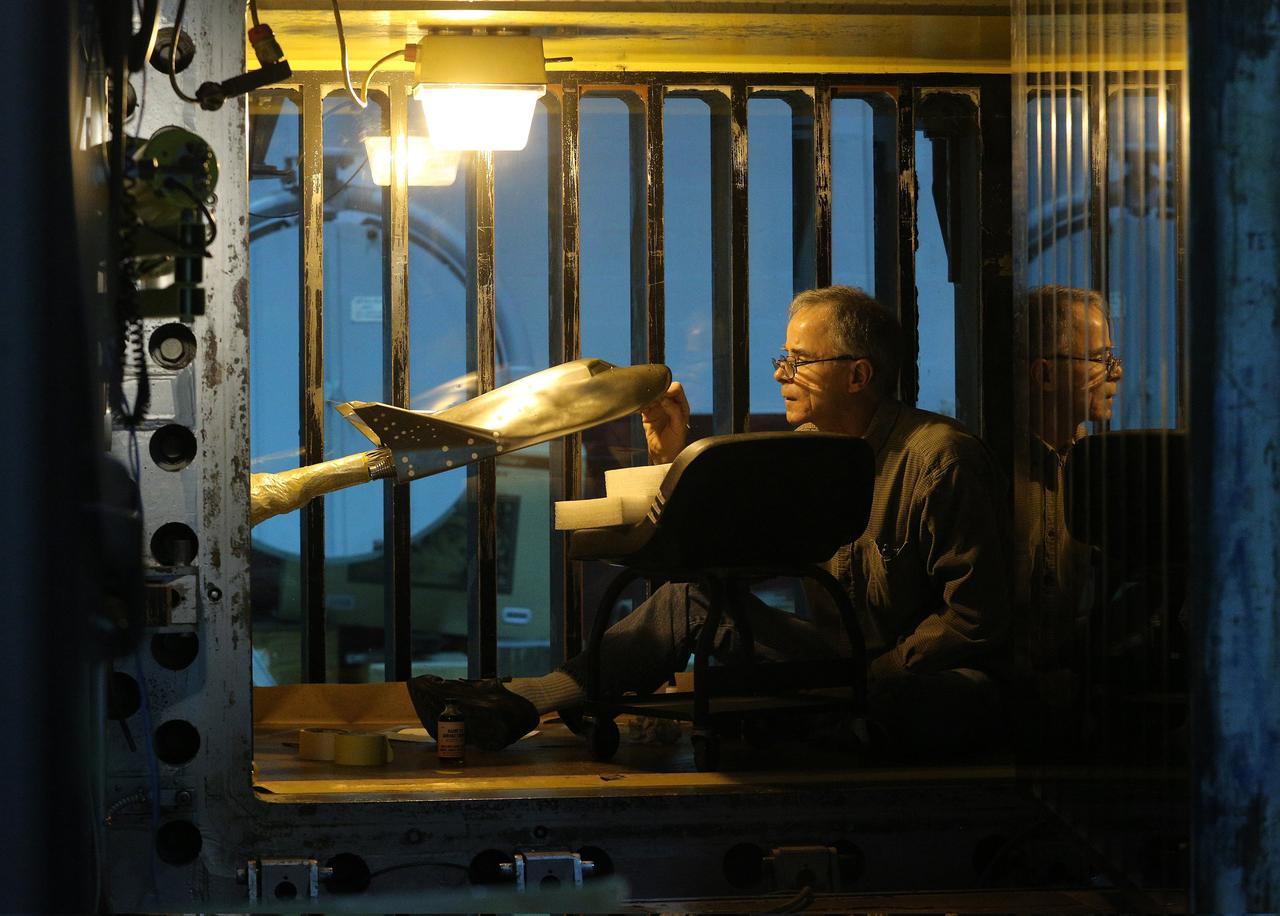
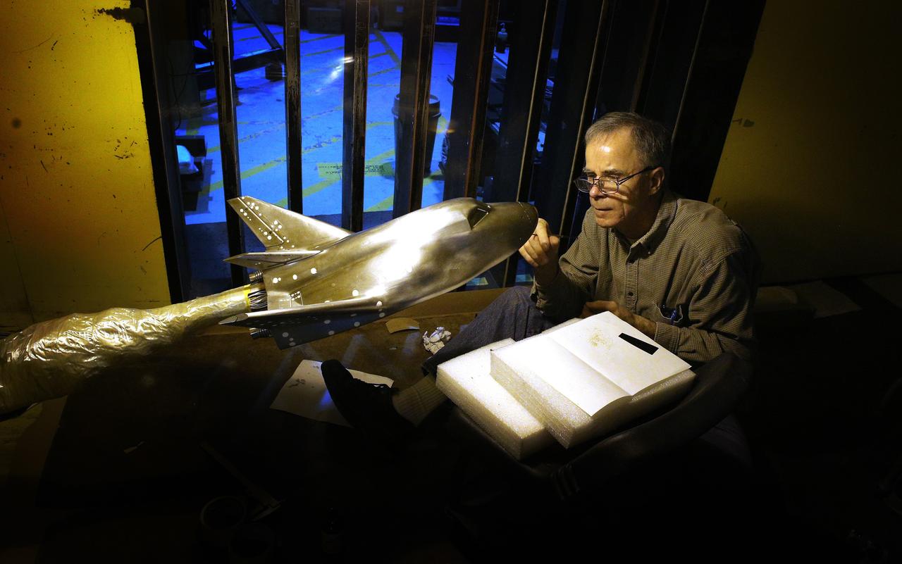
NASA researcher Norman W. Schaeffler adjusts a propellor, which is part of a 7-foot wing model that was recently tested at NASA’s Langley Research Center in Hampton, Virginia. In May and June, NASA researchers tested the wing in the 14-by-22-Foot Subsonic Wind Tunnel to collect data on critical propeller-wing interactions. The lessons learned from this testing will be shared with the public to support advanced air mobility aircraft development.
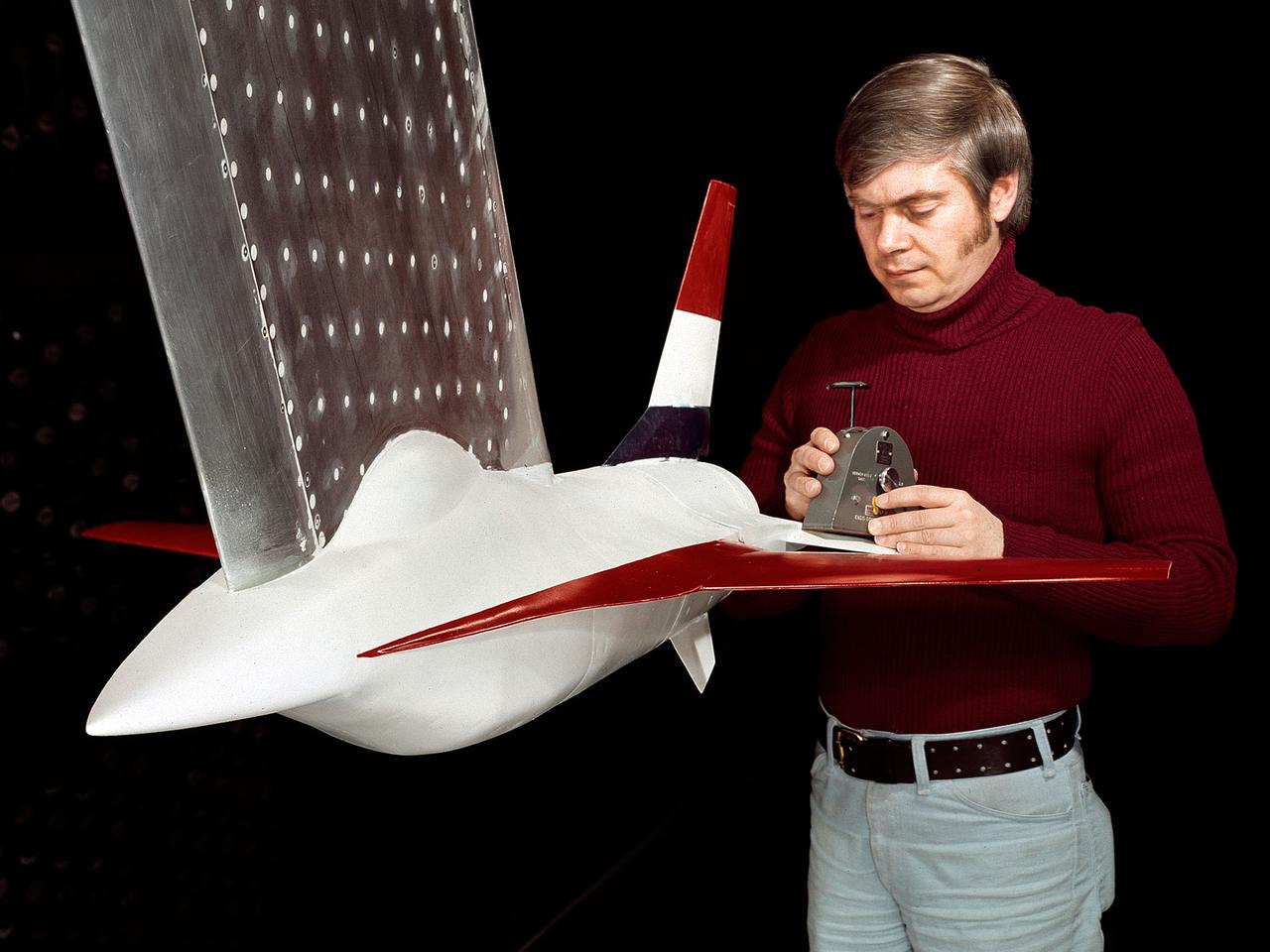
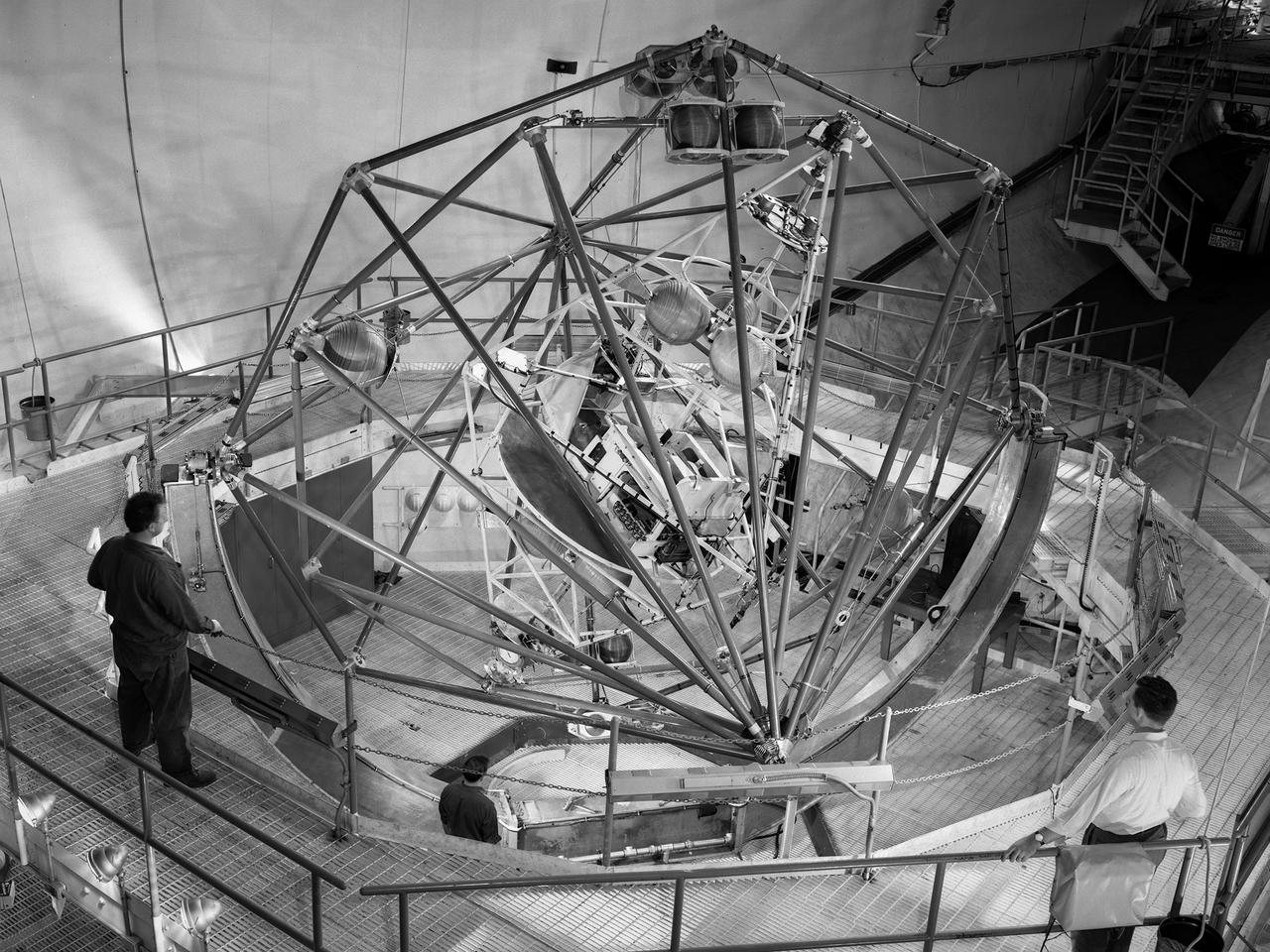
A 1/10th Scale Model of the X-15 research plane is prepared in Langley's 7 x 10 Foot Wind Tunnel for studies relating to spin characteristics. -- Photograph published in Winds of Change, 75th Anniversary NASA publication (page 66), by James Schultz.
The Mercury space capsule undergoing tests in Full Scale Wind Tunnel, January 1959. Photograph published in Winds of Change, 75th Anniversary NASA publication, page 75, by James Schultz. Also Photograph published in Engineer in Charge: A History of the Langley Aeronautical Laboratory, 1917-1958, page 389, by James R. Hansen.
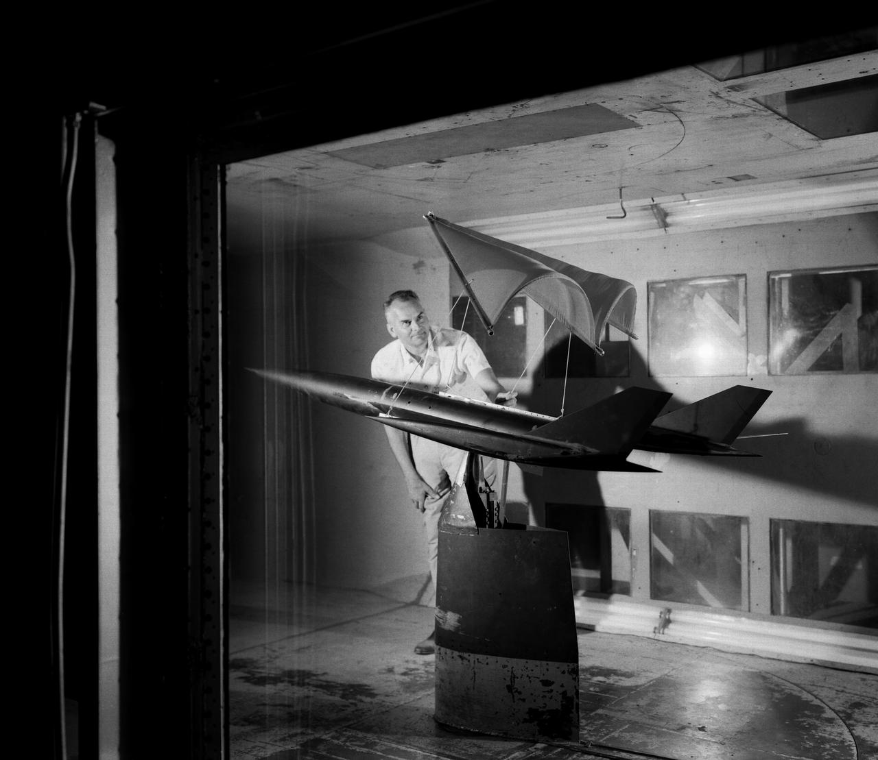
On June 26, 1959, then-Langley-research Francis Rogallo examined the Rogallo wing in the 7x10 FT Tunnel. Originally conceived as a means of bringing manned spacecraft to controlled, soft landings, Rogallo's concept was avidly embraced by later generations of hang-gliding enthusiasts. -- Photograph published in Winds of Change, 75th Anniversary NASA publication (page 18), by James Schultz.
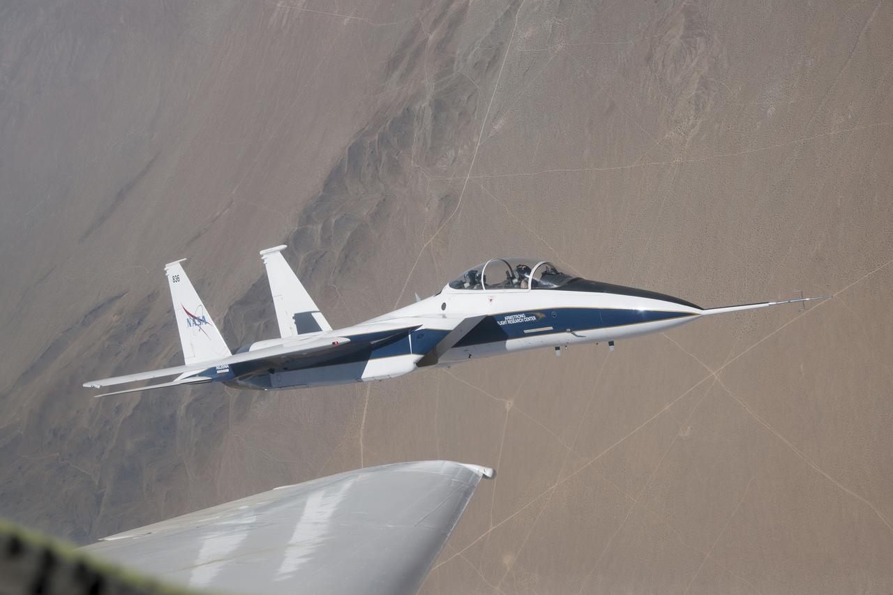
NASA’s F-15 research test bed will expose the Swept Wing Laminar Flow test article to speeds up to Mach 2, matching conditions presented during wind tunnel testing at NASA’s Langley Research Center.
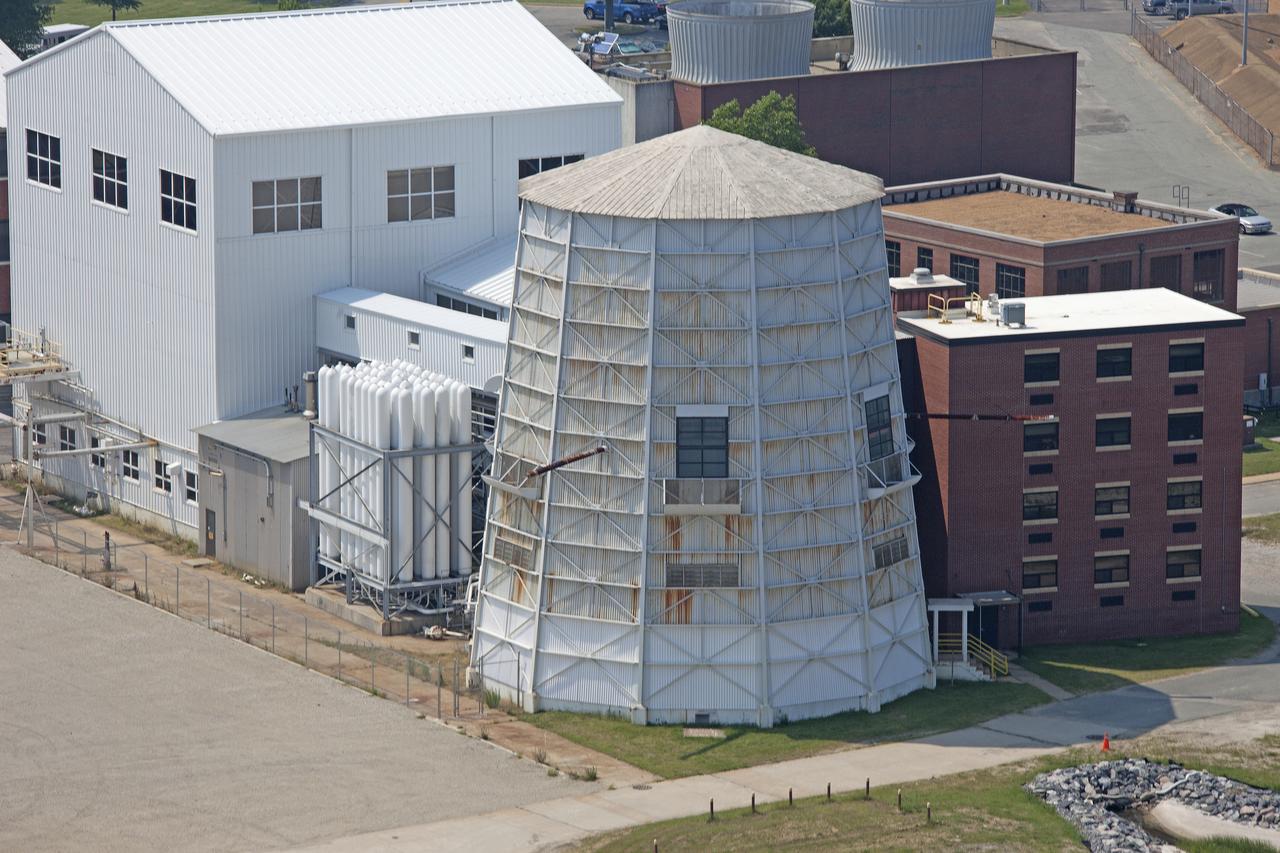
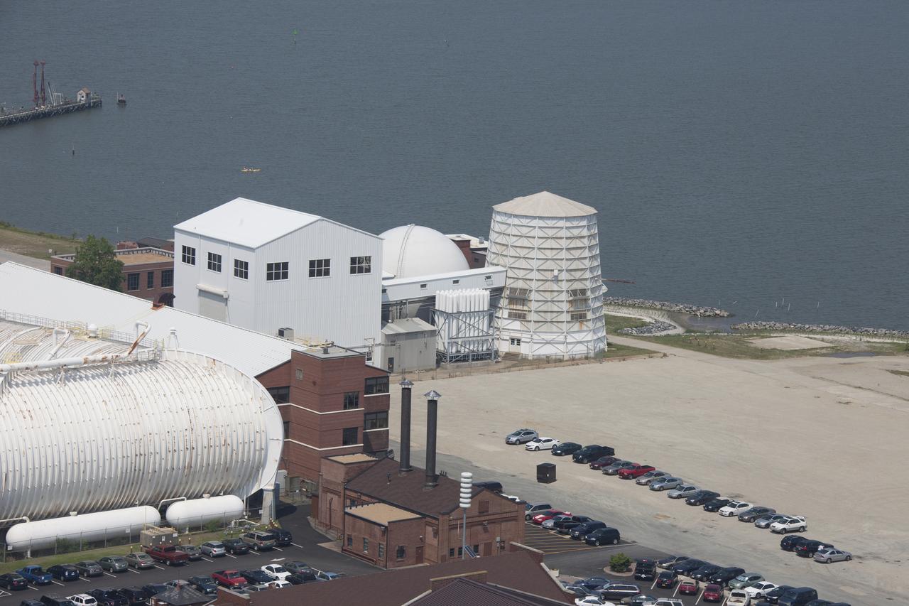
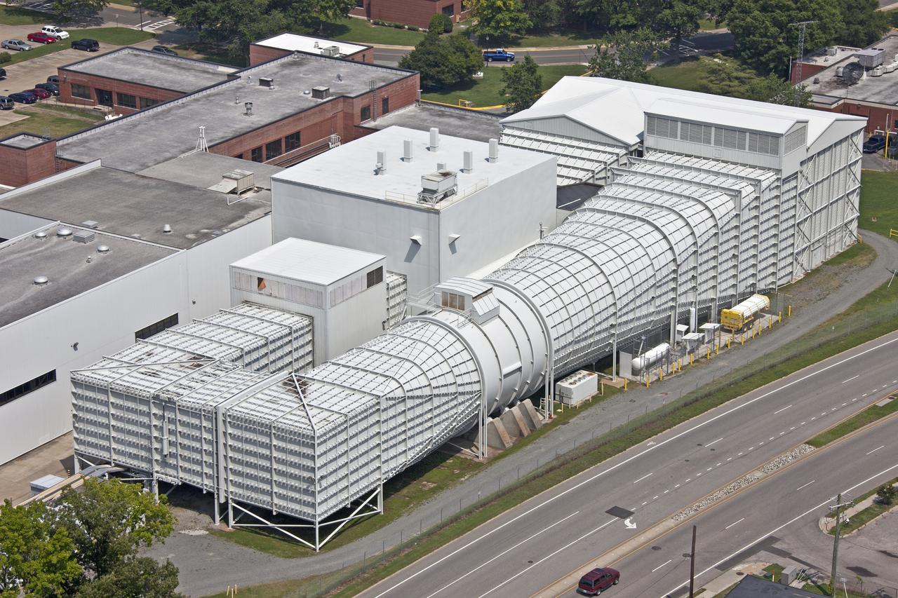
Aerial of NASA Langley East side spin tunnel and wind tunnel
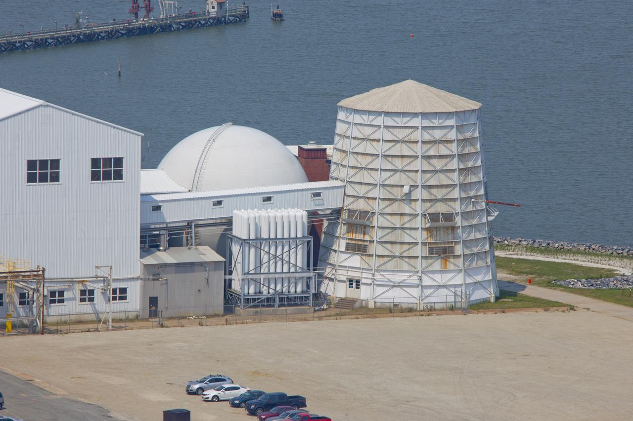
Aerial of NASA Langley East side spin tunnel and wind tunnel
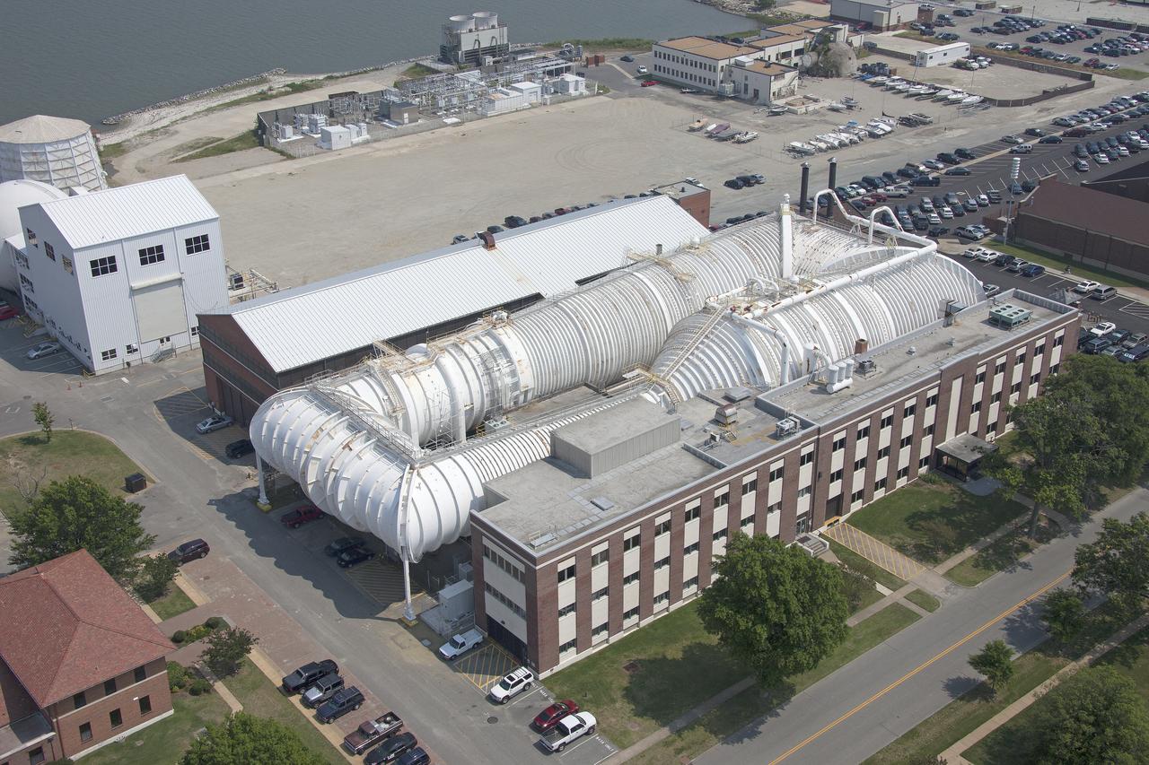
Aerial of NASA Langley East side spin tunnel and wind tunnel
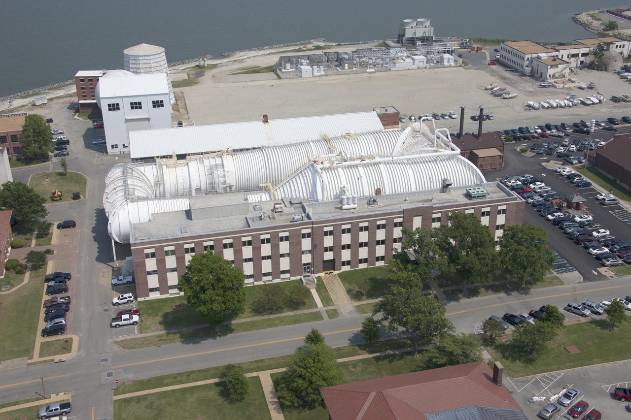
Aerial of NASA Langley East side spin tunnel and wind tunnel
Aerial of NASA Langley East side spin tunnel and wind tunnel
Aerial of NASA Langley East side spin tunnel and wind tunnel
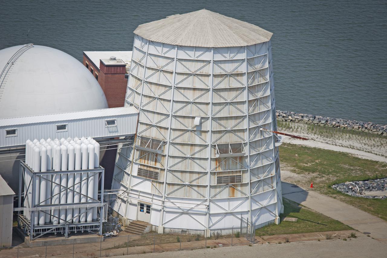
Aerial of NASA Langley East side spin tunnel and wind tunnel
Aerial of NASA Langley East side spin tunnel and wind tunnel
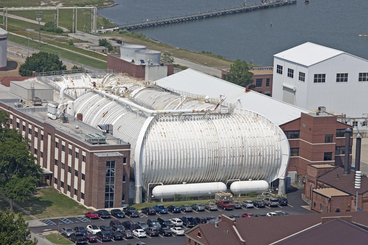
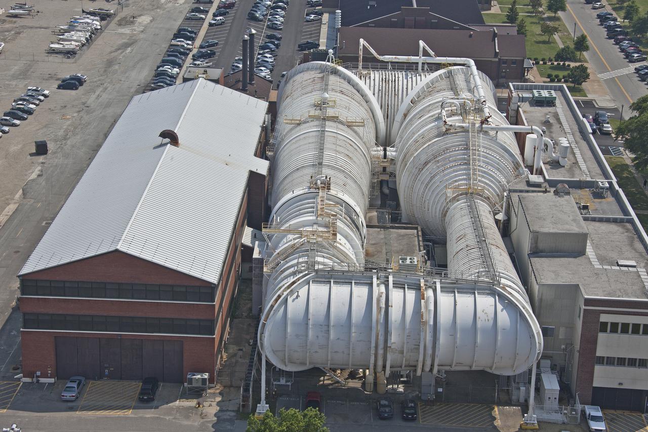
Aerial of NASA Langley Wind Tunnel
As part of the project FIRE study, technicians ready materials to be subjected to high temperatures that will simulate the effects of re-entry heating. Tests of various space capsule materials for Project FIRE were conducted. Photographed in the 9 X 6 Foot Thermal Structures Tunnel. Photograph published in Winds of Change, 75th Anniversary NASA publication, by James Schultz (page 78). Photograph also published in Engineer in Charge: A History of the Langley Aeronautical Laboratory, 1917-1958 by James R. Hansen (page 476). Also Published in the book " A Century at Langley" by Joseph Chambers. Pg. 92
Aerial of NASA Langley Research Center Wind Tunnel
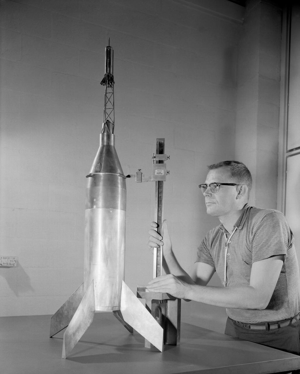
Publicity photograph of a technician measuring a wind tunnel model of the Little Joe test vehicle. Joseph Shortal noted that (vol. 3, p. 29): The largest project at Wallops in support of Mercury was the Little Joe project, designed to qualify the abort-escape system under flight conditions. James Hansen (p. 47) writes: STG engineers Max Faget and Paul Purser, then of Langley's PARD, had conceived Little Joe as a space capsule test vehicle even before the establishment of NASA and the formation of the STG. Girlruth understood the importance of the Little Joe tests: We had to be sure there were no serious performance and operational problems that we had simply not thought of in such a new and radical type of flight vehicle. -- Published in James R. Hansen, Spaceflight Revolution: NASA Langley Research Center From Sputnik to Apollo, (Washington: NASA, 1995), p. 47 Joseph A. Shortal, History of Wallops Station: Origins and Activities Through 1949, (Wallops Island, VA: National Aeronautics and Space Administration, Wallops Station, nd), Comment Edition.

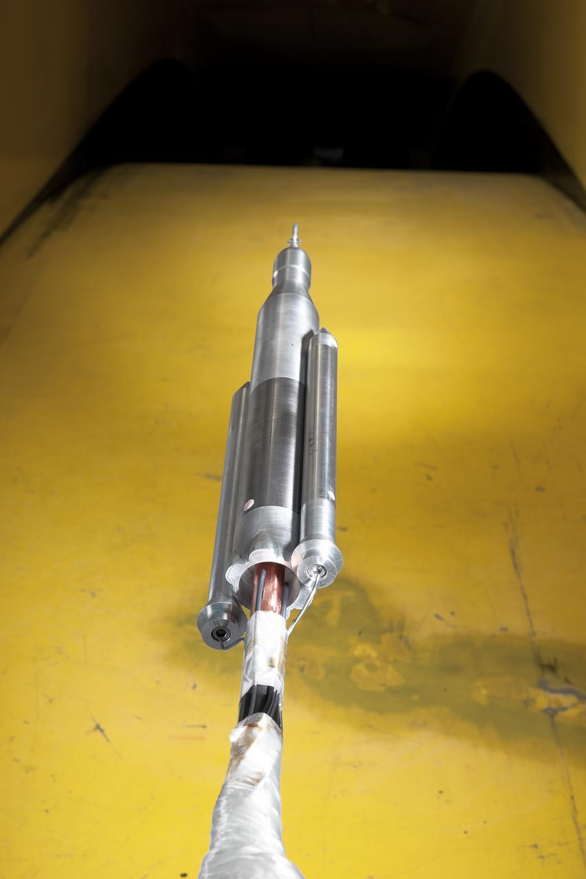
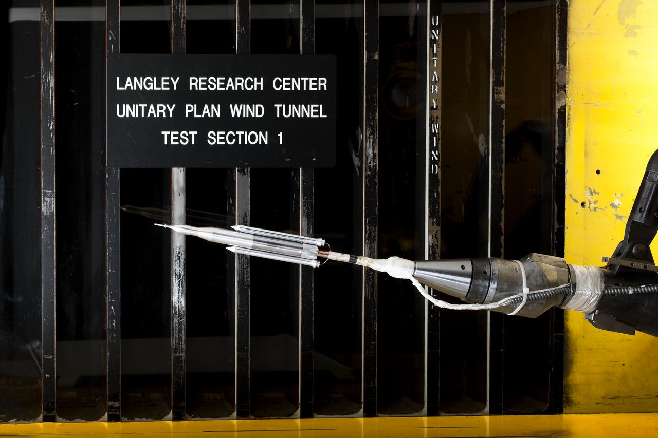
0.4 Percent Scale Space Launch System Wind Tunnel Test 0.4 Percent Scale SLS model installed in the NASA Langley Research Center Unitary Plan Wind Tunnel Test Section 1 for aerodynamic force and movement testing.
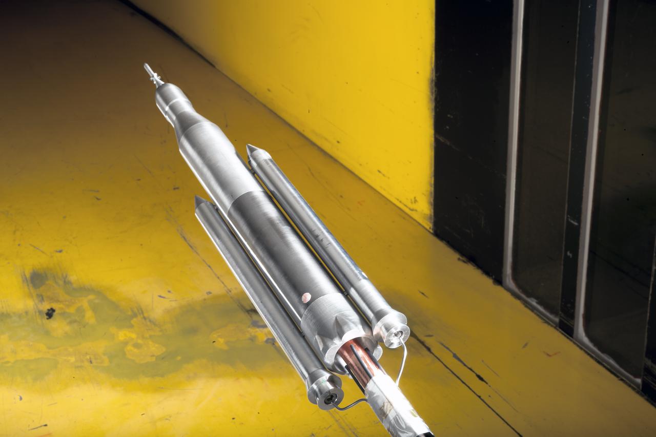
0.4 Percent Scale Space Launch System Wind Tunnel Test 0.4 Percent Scale SLS model installed in the NASA Langley Research Center Unitary Plan Wind Tunnel Test Section 1 for aerodynamic force and movement testing.
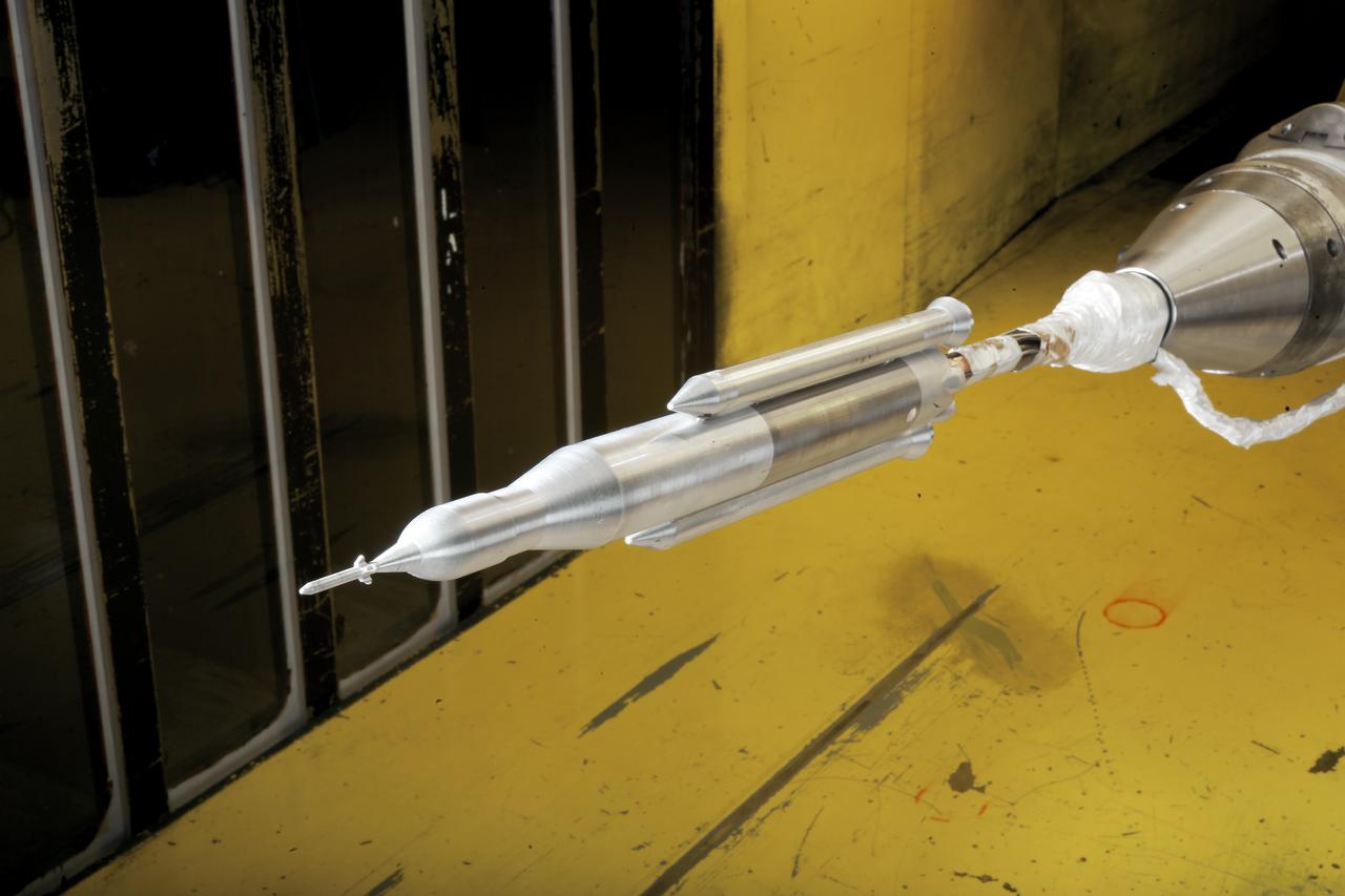
0.4 Percent Scale Space Launch System Wind Tunnel Test 0.4 Percent Scale SLS model installed in the NASA Langley Research Center Unitary Plan Wind Tunnel Test Section 1 for aerodynamic force and movement testing.
0.4 Percent Scale Space Launch System Wind Tunnel Test 0.4 Percent Scale SLS model installed in the NASA Langley Research Center Unitary Plan Wind Tunnel Test Section 1 for aerodynamic force and movement testing.
0.4 Percent Scale Space Launch System Wind Tunnel Test 0.4 Percent Scale SLS model installed in the NASA Langley Research Center Unitary Plan Wind Tunnel Test Section 1 for aerodynamic force and movement testing.
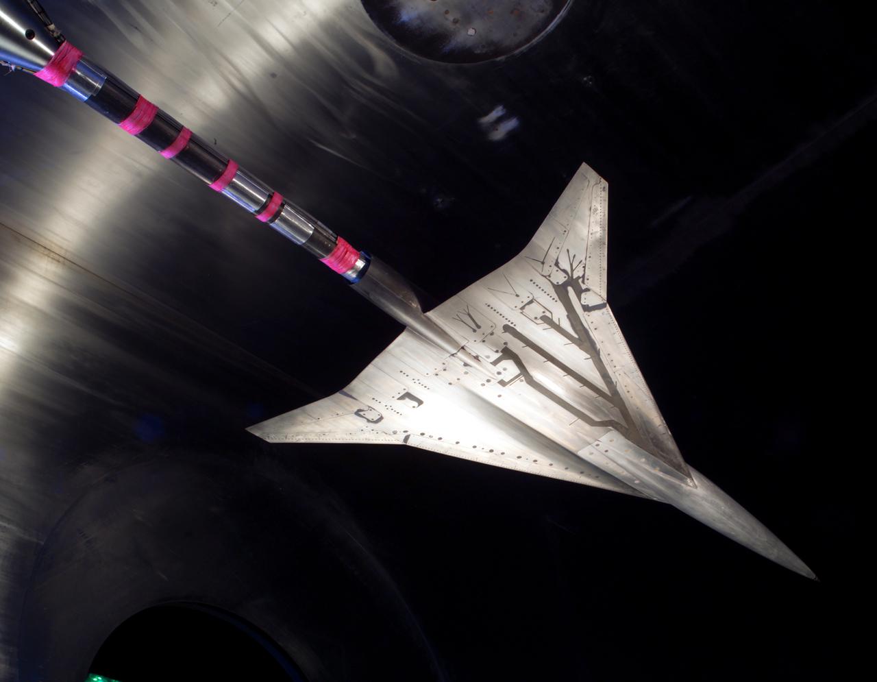
NASA Glenn/NASA Langley, Loads Comparison Test With 6 Component Force/Moment Balance and 1.7% High Speed Research, HSR Model 5. In the Glenn Research Center 10x10 Foot Supersonic Wind Tunnel, SWT
NASA GLENN/NASA LANGLEY LOADS COMPARISON TEST WITH 6 COMPONENT FORCE/MOMENT BALANCE AND 1.7% HIGH SPEED RESEARCH MODEL 5. in the 10x10 super sonic wind tunnel
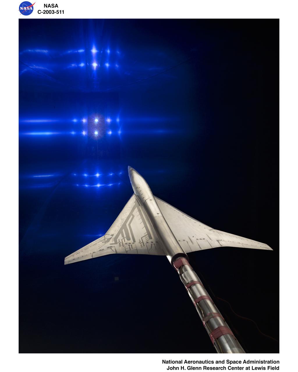
NASA GLENN/NASA LANGLEY LOADS COMPARISON TEST WITH 6 COMPONENT FORCE/MOMENT BALANCE AND 1.7% HIGH SPEED RESEARCH MODEL 5.l in the 10x10 supersonic wind tunnel
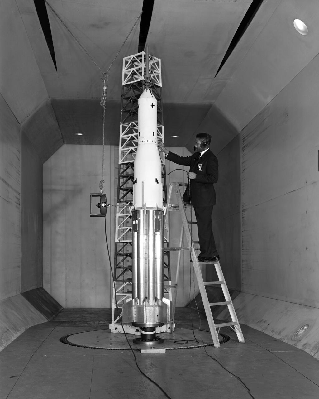
Apollo/Saturn 1B aerodynamic integrity.Jacket description is Ground Wind Loads Effect on SA5 in TDT. Person in 63-1637 is Engineer Thomas A. Byrdsong checks the Apollo/Saturn 1B ground-wind-loads model in the NASA Langley Transonic Dynamics Tunnel.
HAMPTON, Va. – A precise scale model of the Dream Chaser spacecraft begins an evaluation inside the Unitary Plan Wind Tunnel at NASA's Langley Research Center in Virginia. The Dream Chaser is in development by Sierra Nevada Corporation in partnership with NASA's Commercial Crew Program. The data gathered from the wind tunnel was used to further test the design through the company's Commercial Crew Integrated Capability agreement with NASA. Photo credit: NASA/ David C. Bowman
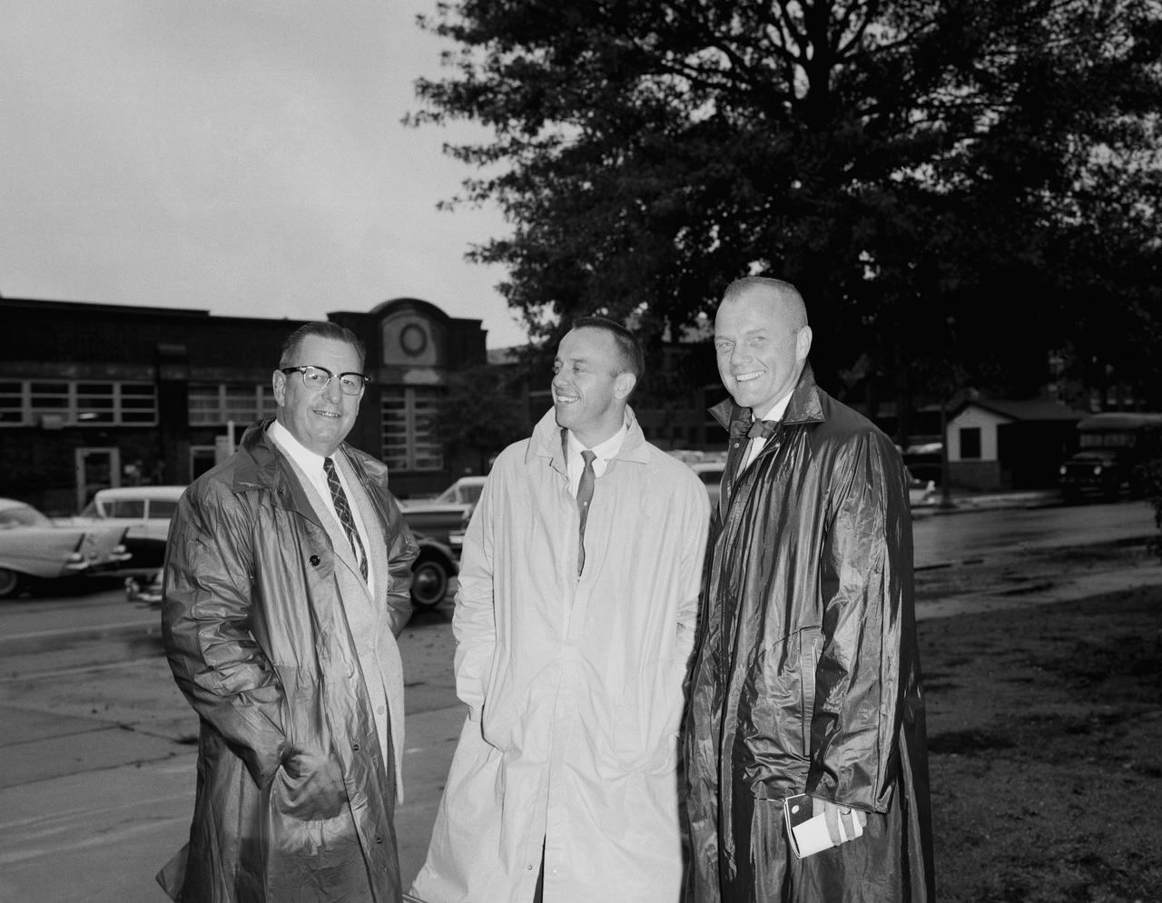
Astronauts at 1959 Langley Inspection. Astronauts at 1959 Langley Inspection: The seven are shown in the Unitary Plan Wind Tunnel NASA Langley. The astronauts left to right: John H. Glenn Jr., M.Scot Carpenter, Virgil I.Grissom, Walter M. Schirra Jr., L. Gordon Cooper, Alan B. Shepard Jr.and Donald K. Slayton.
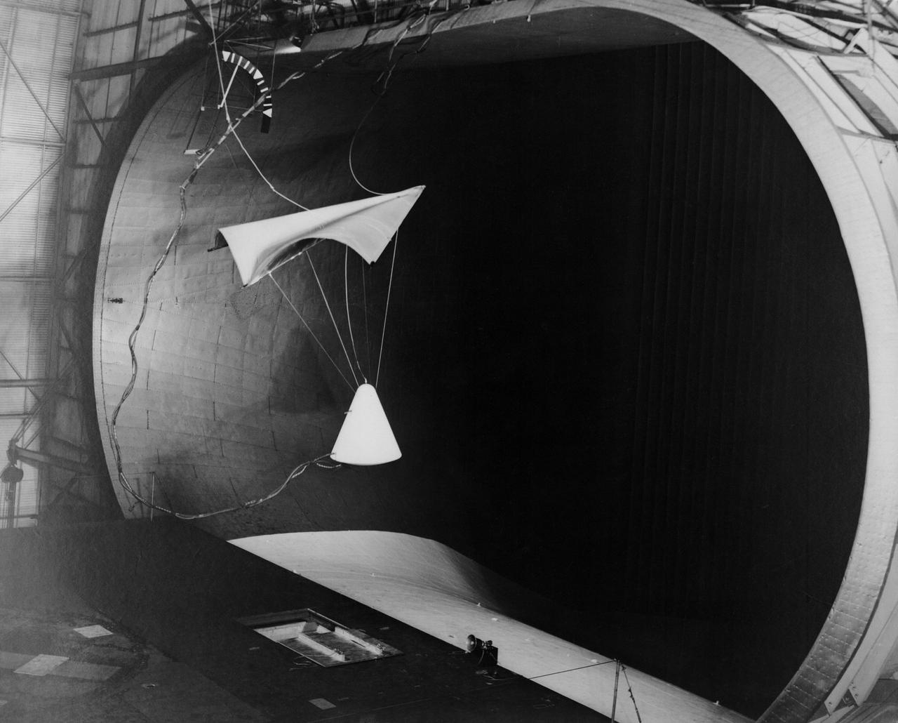
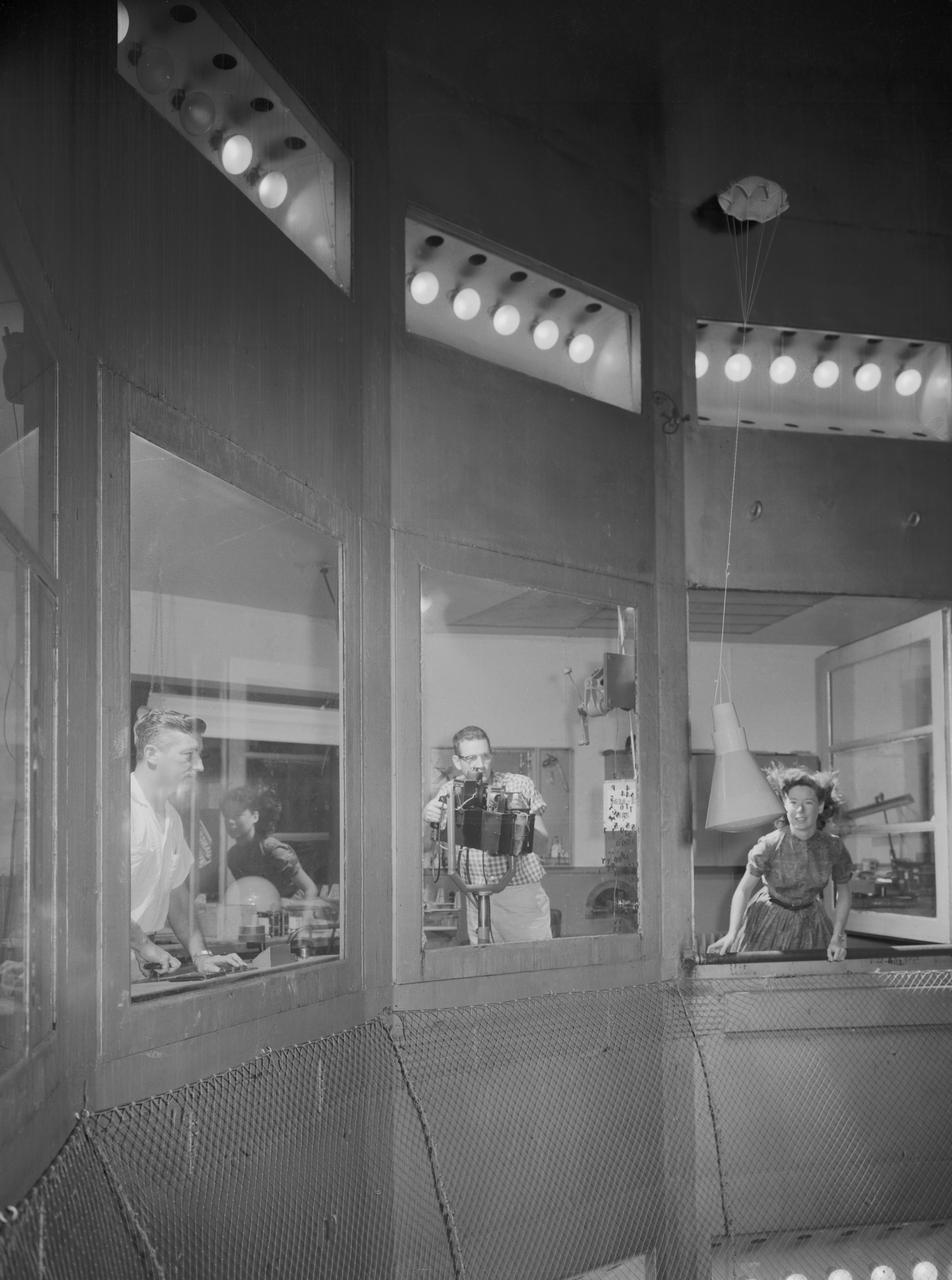
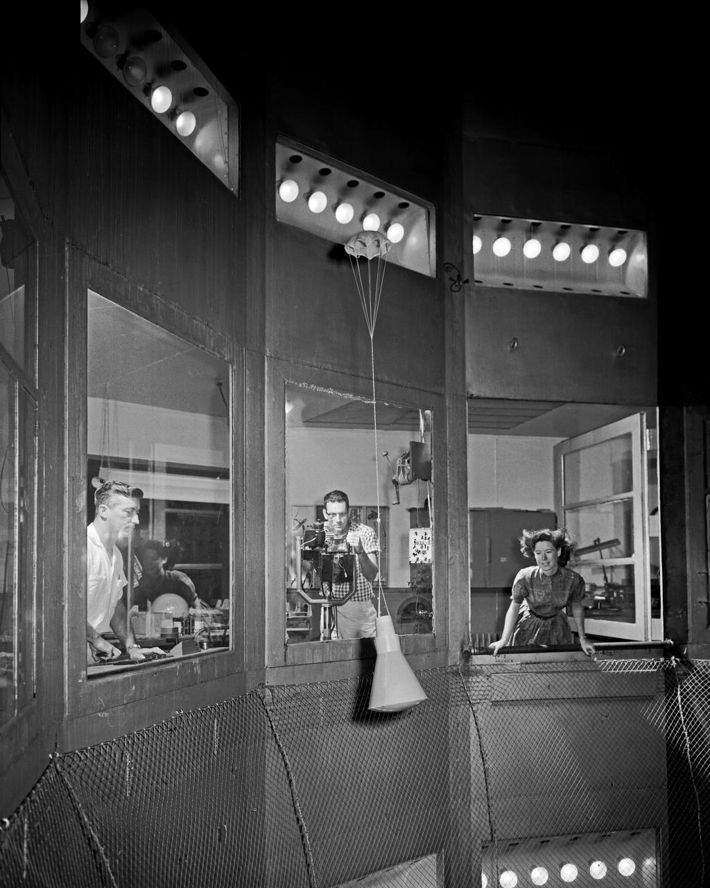
Image L61-4369 is available as an electronic file from the photo lab. See URL. -- Photographed on 06/30/1961. -- Test of parawing in Full Scale Wind Tunnel. -- Published in James R. Hansen, Spaceflight Revolution: NASA Langley Research Center From Sputnik to Apollo, (Washington: NASA, 1995), pp. 380-387.
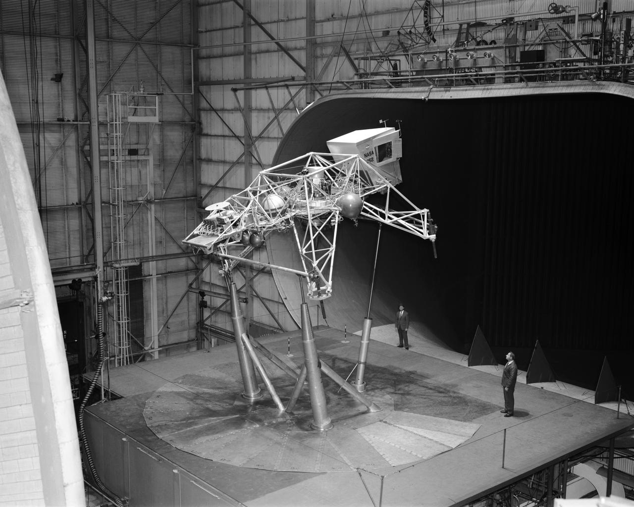
Concept model of the Lunar Excursion Module tested in the Full-Scale wind tunnel. -- Published in James R. Hansen, Spaceflight Revolution: NASA Langley Research Center From Sputnik to Apollo, (Washington: NASA, 1995), p. 356.-L69-670 Bell Lunar Landing Training Vehicle (LLTV): Following the crash of a sister Lunar Landing Training Vehicle at Ellington Field in Houston, Texas, the LLTV NASA 952 was sent from Houston to Langley for tests in the 30 x 60 Full Scale Tunnel. The LLTV was returned to Houston for further training use a short time later. NASA 952 is now on exhibit at the Johnson Space Center in Houston, Texas.
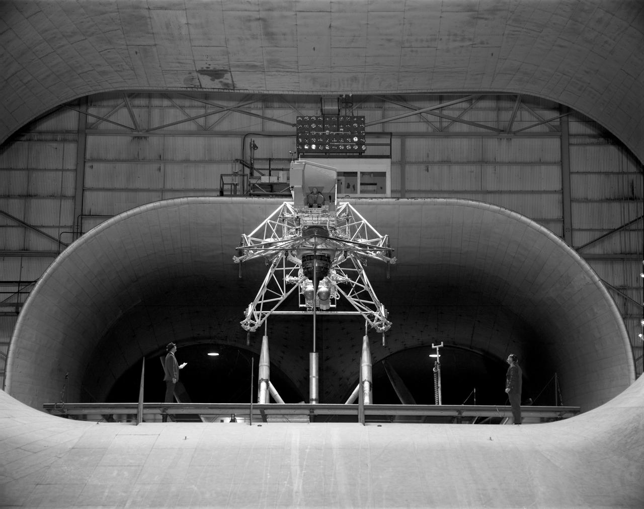
Concept model of the Lunar Excursion Module tested in the Full-Scale wind tunnel. -- Published in James R. Hansen, Spaceflight Revolution: NASA Langley Research Center From Sputnik to Apollo, (Washington: NASA, 1995), p. 356.-L69-670 Bell Lunar Landing Training Vehicle (LLTV): Following the crash of a sister Lunar Landing Training Vehicle at Ellington Field in Houston, Texas, the LLTV NASA 952 was sent from Houston to Langley for tests in the 30 x 60 Full Scale Tunnel. The LLTV was returned to Houston for further training use a short time later. NASA 952 is now on exhibit at the Johnson Space Center in Houston, Texas.
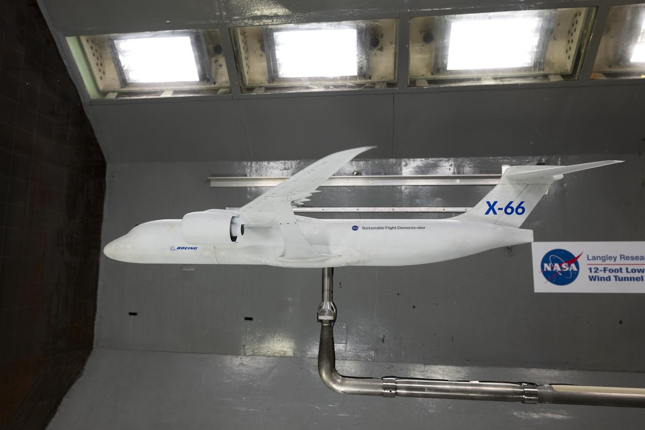
A model of the X-66 aircraft with a wingspan of almost 6 feet was placed in the 12-Foot Low-Speed Wind Tunnel at NASA’s Langley Research Center in Hampton, Virginia on October 30, 2024. During the tests, the team captured measurements of forces such as lift and drag over many aerodynamic configurations and flight conditions.
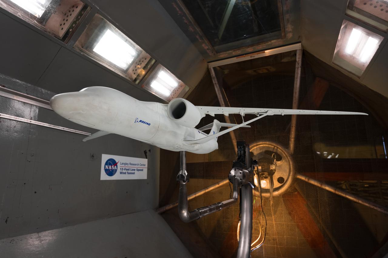
A model of the X-66 aircraft with a wingspan of almost 6 feet was placed in the 12-Foot Low-Speed Wind Tunnel at NASA’s Langley Research Center in Hampton, Virginia on October 30, 2024. During the tests, the team captured measurements of forces such as lift and drag over many aerodynamic configurations and flight conditions.
The Orion aerosciences team has performed more than 30 tests across the United States in support of the program, investigating the heating of the spacecraft during re-entry into Earth’s atmosphere. Testing recently concluded at NASA’s Langley Research Center in Hampton, Virginia with a 6-inch Orion heat shield model in the 20-inch Mach 6 wind tunnel, shown here on Feb. 4, 2019. The team includes engineers at Langley, NASA’s Johnson Space Center in Houston, Texas, and NASA’s Ames Research Center in Silicon Valley.
The Orion aerosciences team has performed more than 30 tests across the United States in support of the program, investigating the heating of the spacecraft during re-entry into Earth’s atmosphere. Testing recently concluded at NASA’s Langley Research Center in Hampton, Virginia with a 6-inch Orion heat shield model in the 20-inch Mach 6 wind tunnel, shown here on Feb. 4, 2019. The team includes engineers at Langley, NASA’s Johnson Space Center in Houston, Texas, and NASA’s Ames Research Center in Silicon Valley.
The Orion aerosciences team has performed more than 30 tests across the United States in support of the program, investigating the heating of the spacecraft during re-entry into Earth’s atmosphere. Testing recently concluded at NASA’s Langley Research Center in Hampton, Virginia with a 6-inch Orion heat shield model in the 20-inch Mach 6 wind tunnel, shown here on Feb. 4, 2019. The team includes engineers at Langley, NASA’s Johnson Space Center in Houston, Texas, and NASA’s Ames Research Center in Silicon Valley.
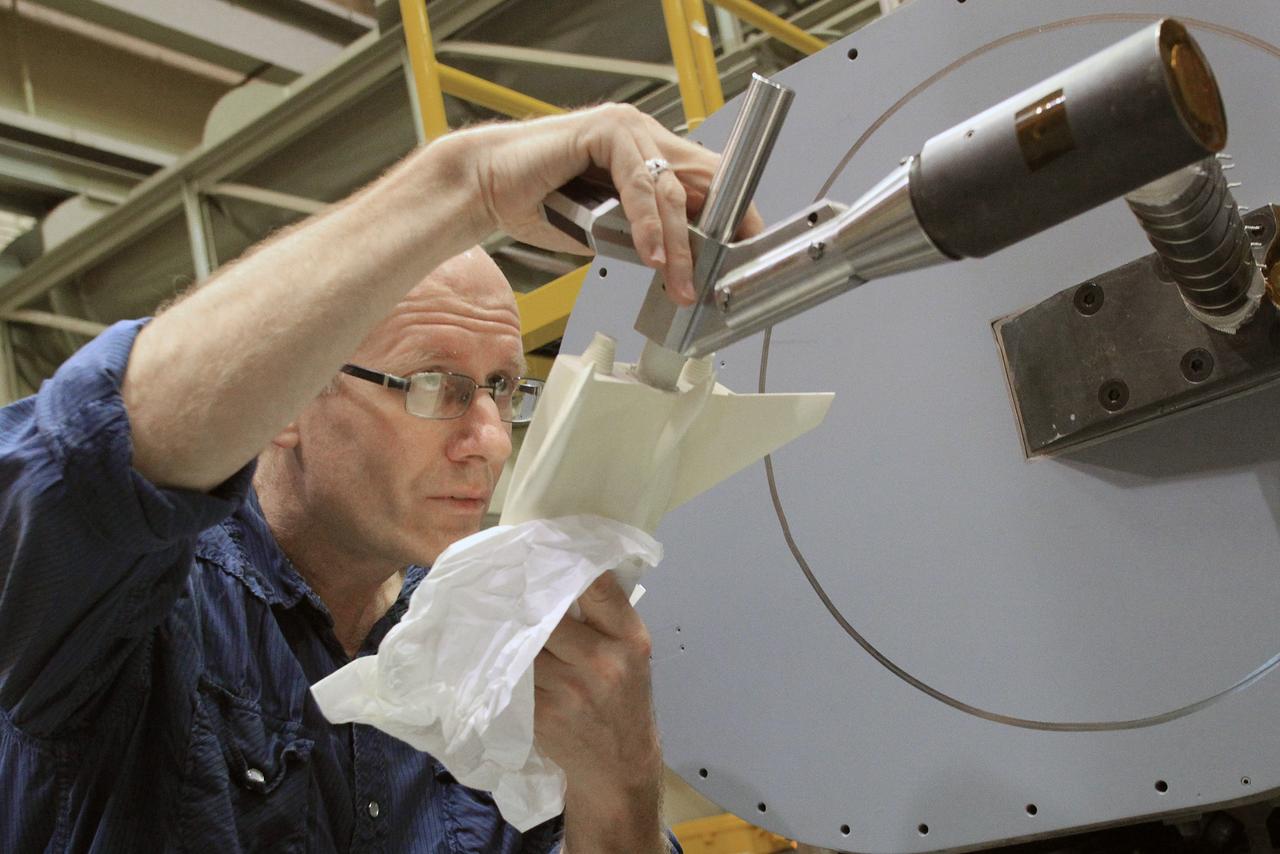
HAMPTON, Va. – NASA technician Ricky Hall works inside the Unitary Plan Wind Tunnel at NASA's Langley Research Center in Virginia to affix grains of sand to a precise scale model of the Dream Chaser spacecraft. Sierra Nevada Corporation is developing the Dream Chaser in partnership with NASA's Commercial Crew Program. The sand creates turbulence at key points to simulate the conditions the real spacecraft will encounter during its return to Earth. The data gathered from the wind tunnel was used to further test the design through the company's Commercial Crew Integrated Capability agreement with NASA. Photo credit: NASA/ David C. Bowman
HAMPTON, Va. – NASA technician Ricky Hall works inside the Unitary Plan Wind Tunnel at NASA's Langley Research Center in Virginia to affix grains of sand to a precise scale model of the Dream Chaser spacecraft. Sierra Nevada Corporation is developing the Dream Chaser in partnership with NASA's Commercial Crew Program. The sand creates turbulence at key points to simulate the conditions the real spacecraft will encounter during its return to Earth. The data gathered from the wind tunnel was used to further test the design through the company's Commercial Crew Integrated Capability agreement with NASA. Photo credit: NASA/ David C. Bowman
A model of the General Dynamics YF-16 Fighting Falcon in the test section of the 8- by 6-Foot Supersonic Wind Tunnel at the National Aeronautics and Space Administration (NASA) Lewis Research Center. The YF-16 was General Dynamics response to the military’s 1972 request for proposals to design a new 20,000-pound fighter jet with exceptional acceleration, turn rate, and range. The aircraft included innovative design elements to help pilots survive turns up to 9Gs, a new frameless bubble canopy, and a Pratt and Whitney 24,000-pound thrust F-100 engine. The YF-16 made its initial flight in February 1974, just six weeks before this photograph, at Edwards Air Force Base. Less than a year later, the Air Force ordered 650 of the aircraft, designated as F-16 Fighting Falcons. The March and April 1974 tests in the 8- by 6-foot tunnel analyzed the aircraft’s fixed-shroud ejector nozzle. The fixed-nozzle area limited drag, but also limited the nozzle’s internal performance. NASA researchers identified and assessed aerodynamic and aerodynamic-propulsion interaction uncertainties associated the prototype concept. YF-16 models were also tested extensively in the 11- by 11-Foot Transonic Wind Tunnel and 9- by 7-Foot Supersonic Wind Tunnel at Ames Research Center and the 12-Foot Pressure Wind Tunnel at Langley Research Center.
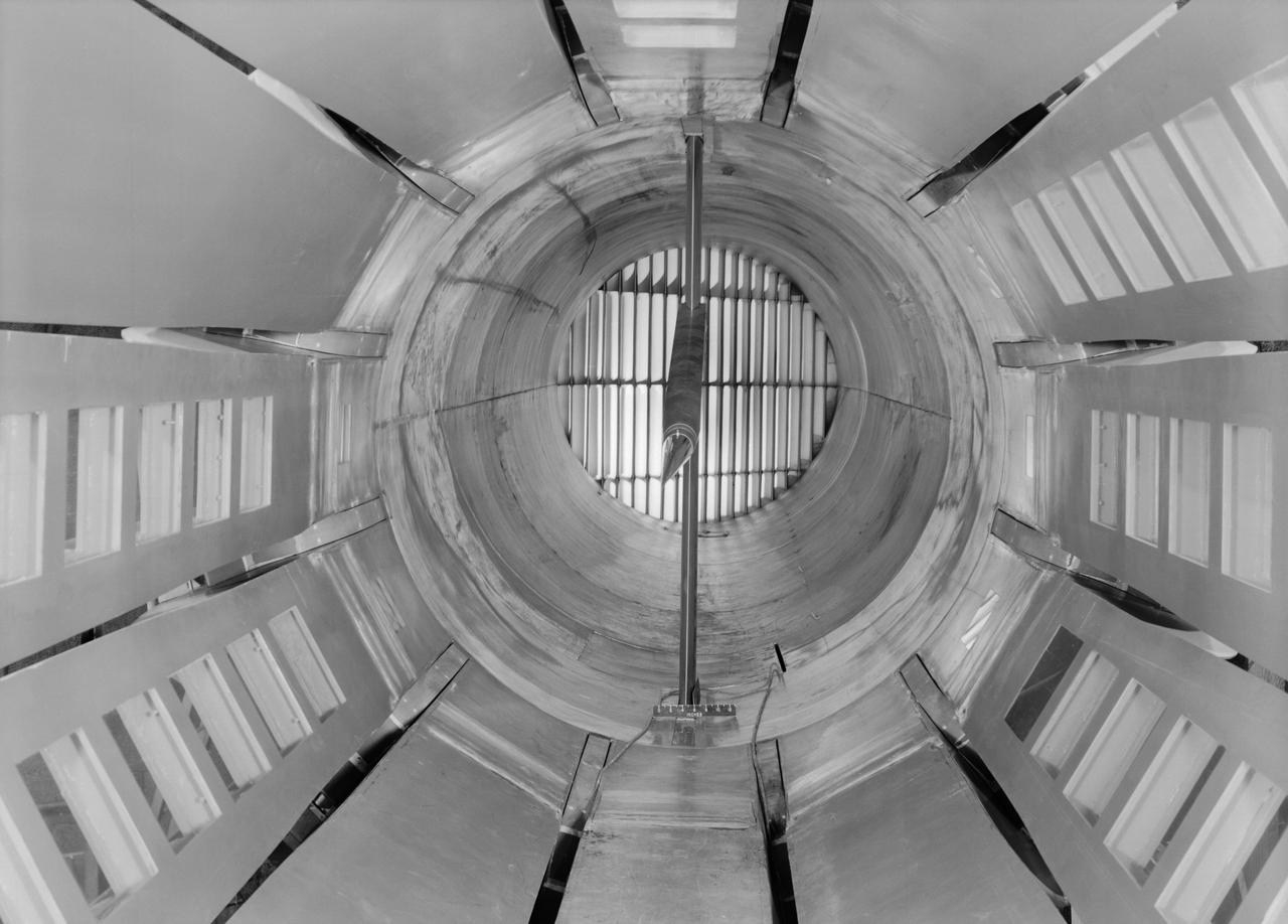
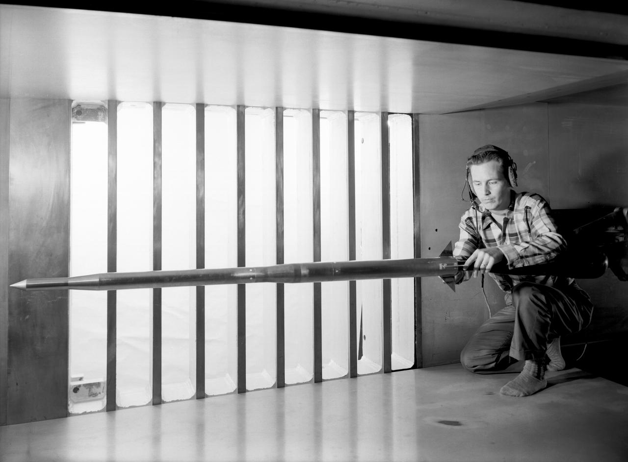
Interior view of the slotted throat test section installed in the 8-Foot High Speed Tunnel (HST) in 1950. The slotted region is about 160 inches in length. In this photograph, the sting-type model support is seen straight on. In a NASA report, the test section is described as follows: The test section of the Langley 8-foot transonic tunnel is dodecagonal in cross section and has a cross-sectional area of about 43 square feet. Longitudinal slots are located between each of the 12 wall panels to allow continuous operation through the transonic speed range. The slots contain about 11 percent of the total periphery of the test section. Six of the twelve panels have windows in them to allow for schlieren observations. The entire test section is enclosed in a hemispherical shaped chamber. John Becker noted that the tunnel s final achievement was the development and use in routine operations of the first transonic slotted throat. The investigations of wing-body shapes in this tunnel led to Whitcomb s discovery of the transonic area rule. James Hansen described the origins of the the slotted throat as follows: In 1946 Langley physicist Ray H. Wright conceived a way to do transonic research effectively in a wind tunnel by placing slots in the throat of the test section. The concept for what became known as the slotted-throat or slotted-wall tunnel came to Wright not as a solution to the chronic transonic problem, but as a way to get rid of wall interference (i.e., the mutual effect of two or more meeting waves or vibrations of any kind caused by solid boundaries) at subsonic speeds. For most of the year before Wright came up with this idea, he had been trying to develop a theoretical understanding of wall interference in the 8-Foot HST, which was then being repowered for Mach 1 capability. When Wright presented these ideas to John Stack, the response was enthusiastic but neither Wright nor Stack thought of slotted-throats as a solution to the transonic problem, only the wall interference problem. It was an accidental discovery which showed that slotted throats might solve the transonic problem. Most engineers were skeptical but Stack persisted. Initially, plans were to modify the 16-Foot tunnel but in the spring of 1948, Stack announced that the 8-Foot HST would also be modified. As Hansen notes: The 8-Foot HST began regular transonic operations for research purposes on 6 October 1950. The concept was a success and led to plans for a new wind tunnel which would be known as the 8-Foot Transonic Pressure Tunnel. -- Published in U.S., National Advisory Committee for Aeronautics, Characteristics of Nine Research Wind Tunnels of the Langley Aeronautical Laboratory, 1957, pp. 17, 22 James R. Hansen, Engineer in Charge, NASA SP-4305, p. 454 and Chapter 11, The Slotted Tunnel and the Area Rule.
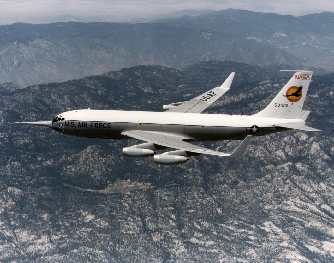
The KC-135 with the winglets in flight over the San Gabriel mountains, south of Edwards AFB. While wind tunnel tests suggested that winglets - developed by NASA Langley's Richard Whitcomb - would significantly reduce drag, flight research proved their usefulness. Winglets were installed on an Air Force KC-135 and research flights were made in 1979 and 1980. These showed drag in flight was reduced by as much as 7 percent. Winglets soon appeared on production aircraft, although these were smaller than those mounted on the KC-135.
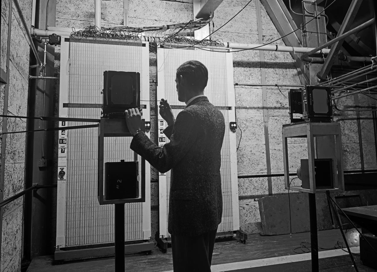
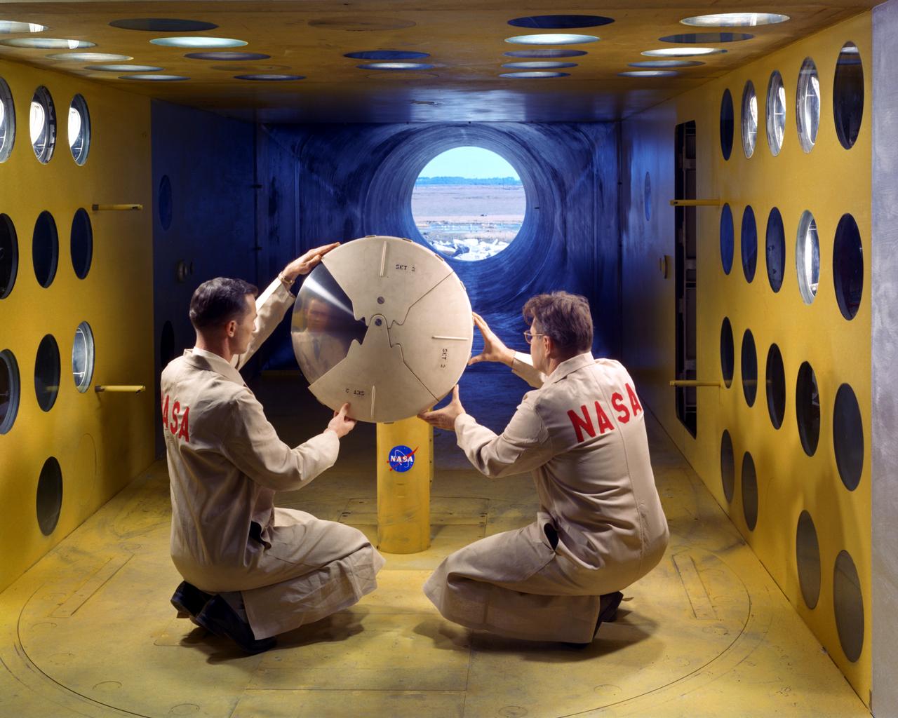
Instrumentation in 16 Foot Wind Tunnel manometer boards

Photo of Sue Grafton taken in advance of the Flight Dynamic Research Facility's (FDRF) ribbon cutting. Sue started as a researcher for the N.A.C.A. and worked in the vertical spin tunnel (VST). She has since worked in the 30x60 full-scale tunnel for many years before its closure and then returned to VST and 12ft (NASA’s oldest operational wind tunnels). She will also be onboard for the commissioning of the FDRF, NASA’s newest wind tunnel.

Sue Grafton, NASA engineer poses in advance of the Flight Dynamic Research Facility's (FDRF) grand opening. Sue started as a researcher for the N.A.C.A. and worked in the vertical spin tunnel (VST). She has since worked in the 30x60 full-scale tunnel for many years before its closure and then returned to VST and 12ft (NASA’s oldest operational wind tunnels). She will also be onboard for the commissioning of the FDRF, NASA’s newest wind tunnel.

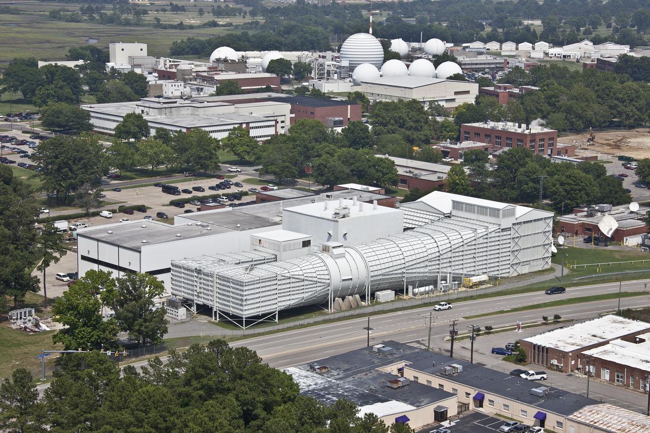
Aerial of 16 ft tunnel
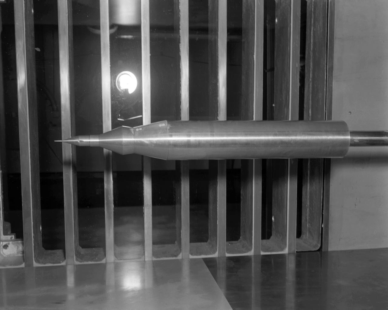
Scout Model in Unitary Wind Tunnel (UWT)
Re-entry vehicle on Full Scale Tunnel (FST)
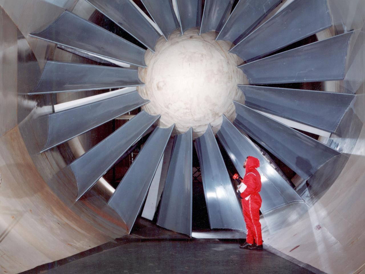
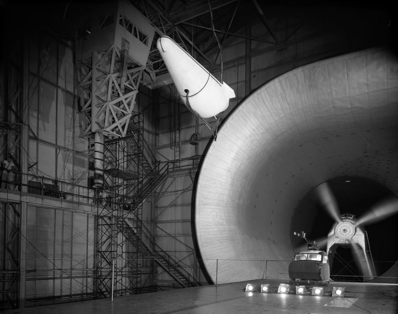
The drive fan for the Icing Research Tunnel at the National Aeronautics and Space Administration (NASA) Lewis Research Center in Cleveland, Ohio. The Lewis Icing Research Program, which began during World War II, utilized both research aircraft and the icing tunnel throughout the 1940s and 1950s. The research program was cancelled in 1958 as Lewis focused on space. The tunnel continued to be used occasionally for industrial customers in the 1960s and early 1970s. Lewis’ icing research was formally reinstituted just months before this photograph in 1978. The Icing Research Tunnel’s original 4100-horsepower induction motor was coupled directly to the 24-foot-diameter fan. Neoprene boots protected the leading edges of the 12 spruce fan blades. The system generated air speeds up to 300 miles per hour through the tunnel’s 6- by 9-foot test section. A large tail faring extended from the center of the fan to uniformly guide the airflow down the tunnel. NASA Headquarters ordered modifications to the Icing Research Tunnel in 1985 after wooden fan blades in a wind tunnel at Langley Research Center failed. Despite the fact that the large hub, seen in the center of the fan, provided an extra layer of protection against blade failure, Headquarters ordered the installation of a new set of wooden blades. The blades were ordered but not installed. The tunnel technicians instead agreed to inspect the fan after each run. A new 5000-horsepower motor was installed in 1987, and the original fan blades were finally replaced in 1993.
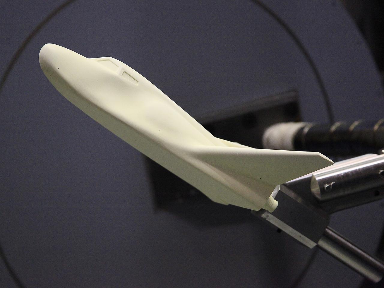
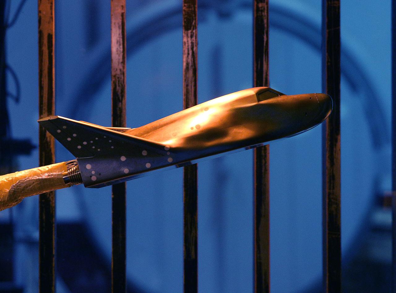
HAMPTON, Va. –A 10-inch long ceramic model of the Sierra Nevada Corporation, or SNC, Dream Chaser spacecraft is prepared for high-speed wind tunnel tests at NASA's Langley Research Center in Hampton, Va. The tests measure how much heat the winged vehicle would experience during ascent and re-entry through the atmosphere, including the spacecraft's lower- and upper-body flaps, elevons and a rudder. They're also helping the company obtain necessary data for the material selection and design of the spacecraft's thermal protection system. SNC is continuing the development of its Dream Chaser spacecraft under the agency's Commercial Crew Integrated Capability, or CCiCap, initiative, which is intended to lead to the availability of commercial human spaceflight services for government and commercial customers. To learn more about CCP and its industry partners, visit www.nasa.gov/commercialcrew. Image credit: NASA/David Bowman

Outlined with gold stripes are the hinged nose strakes, modifications made to NASA's F-18 HARV (High Alpha Research Vehicle) at the Dryden Flight Research Center, Edwards, California. Actuated Nose Strakes for Enhanced Rolling (ANSER) were installed to fly the third and final phase in the HARV flight test project. Normally folded flush, the units -- four feet long and six inches wide -- can be opened independently to interact with the nose vortices to produce large side forces for control. Early wind tunnel tests indicated that the strakes would be as effective in yaw control at high angles of attack as rudders are at lower angles. Testing involved evaluation of the strakes by themselves as well as combined with the aircraft's Thrust Vectoring System. The strakes were designed by NASA's Langley Research Center, then installed and flight tested at Dryden.
HAMPTON, Va. –A 10-inch long ceramic model of the Sierra Nevada Corporation, or SNC, Dream Chaser spacecraft is prepared for high-speed wind tunnel tests at NASA's Langley Research Center in Hampton, Va. The tests measure how much heat the winged vehicle would experience during ascent and re-entry through the atmosphere, including the spacecraft's lower- and upper-body flaps, elevons and a rudder. They're also helping the company obtain necessary data for the material selection and design of the spacecraft's thermal protection system. SNC is continuing the development of its Dream Chaser spacecraft under the agency's Commercial Crew Integrated Capability, or CCiCap, initiative, which is intended to lead to the availability of commercial human spaceflight services for government and commercial customers. To learn more about CCP and its industry partners, visit www.nasa.gov/commercialcrew. Image credit: NASA/David Bowman
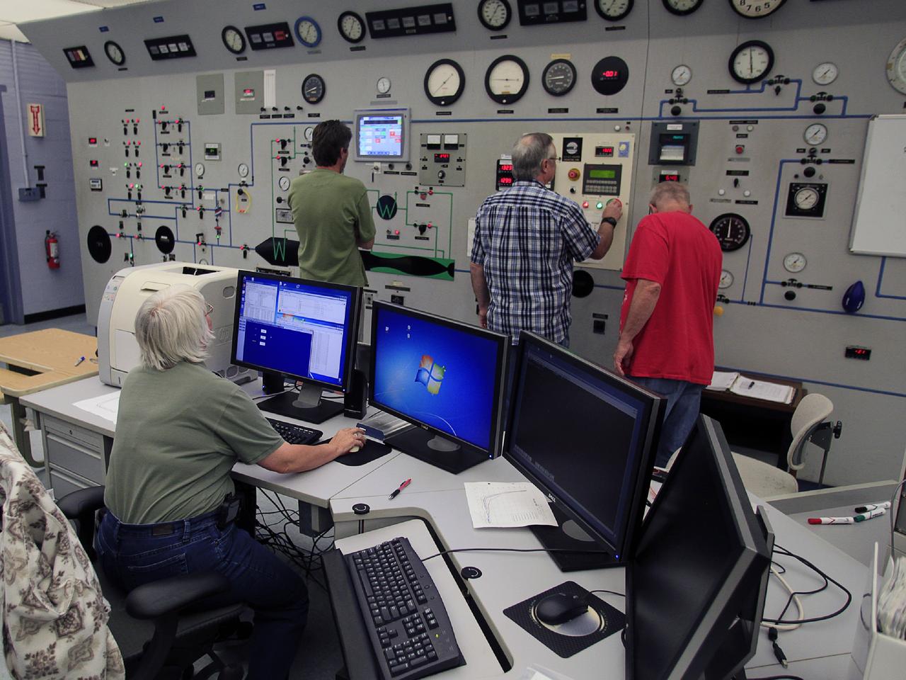
HAMPTON, Va. –Engineers monitor high-speed wind tunnel testing of a 10-inch long ceramic model of the Sierra Nevada Corporation, or SNC, Dream Chaser spacecraft at NASA's Langley Research Center in Hampton, Va. The tests measure how much heat the winged vehicle would experience during ascent and re-entry through the atmosphere, including the spacecraft's lower- and upper-body flaps, elevons and a rudder. They're also helping the company obtain necessary data for the material selection and design of the spacecraft's thermal protection system. SNC is continuing the development of its Dream Chaser spacecraft under the agency's Commercial Crew Integrated Capability, or CCiCap, initiative, which is intended to lead to the availability of commercial human spaceflight services for government and commercial customers. To learn more about CCP and its industry partners, visit www.nasa.gov/commercialcrew. Image credit: NASA/David Bowman
HAMPTON, Va. –An engineer monitors high-speed wind tunnel testing of a 10-inch long ceramic model of the Sierra Nevada Corporation, or SNC, Dream Chaser spacecraft at NASA's Langley Research Center in Hampton, Va. The tests measure how much heat the winged vehicle would experience during ascent and re-entry through the atmosphere, including the spacecraft's lower- and upper-body flaps, elevons and a rudder. They're also helping the company obtain necessary data for the material selection and design of the spacecraft's thermal protection system. SNC is continuing the development of its Dream Chaser spacecraft under the agency's Commercial Crew Integrated Capability, or CCiCap, initiative, which is intended to lead to the availability of commercial human spaceflight services for government and commercial customers. To learn more about CCP and its industry partners, visit www.nasa.gov/commercialcrew. Image credit: NASA/David Bowman
HAMPTON, Va. –A 10-inch long ceramic model of the Sierra Nevada Corporation, or SNC, Dream Chaser spacecraft undergoes high-speed wind tunnel tests at NASA's Langley Research Center in Hampton, Va. The tests measure how much heat the winged vehicle would experience during ascent and re-entry through the atmosphere, including the spacecraft's lower- and upper-body flaps, elevons and a rudder. They're also helping the company obtain necessary data for the material selection and design of the spacecraft's thermal protection system. SNC is continuing the development of its Dream Chaser spacecraft under the agency's Commercial Crew Integrated Capability, or CCiCap, initiative, which is intended to lead to the availability of commercial human spaceflight services for government and commercial customers. To learn more about CCP and its industry partners, visit www.nasa.gov/commercialcrew. Image credit: NASA/David Bowman
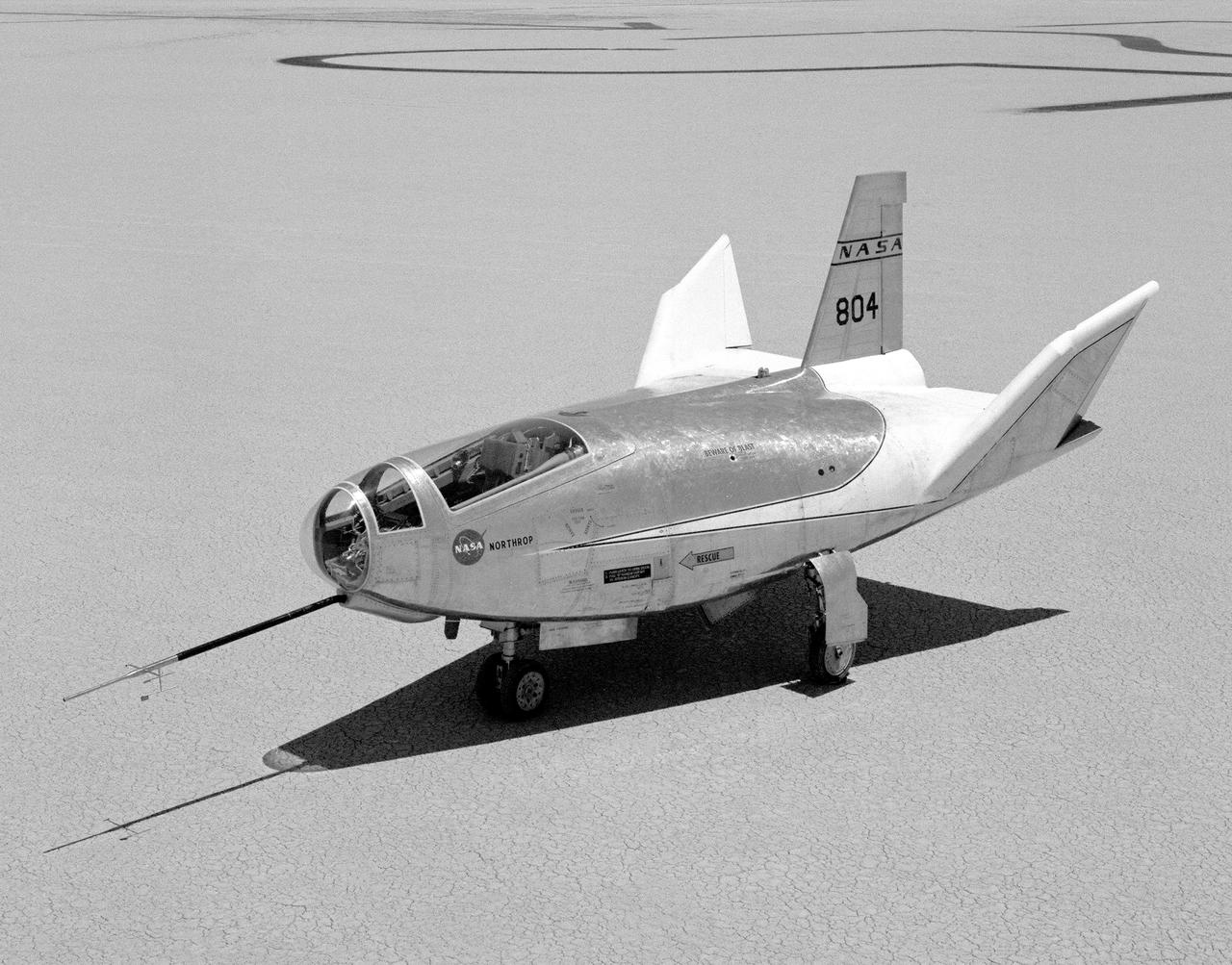
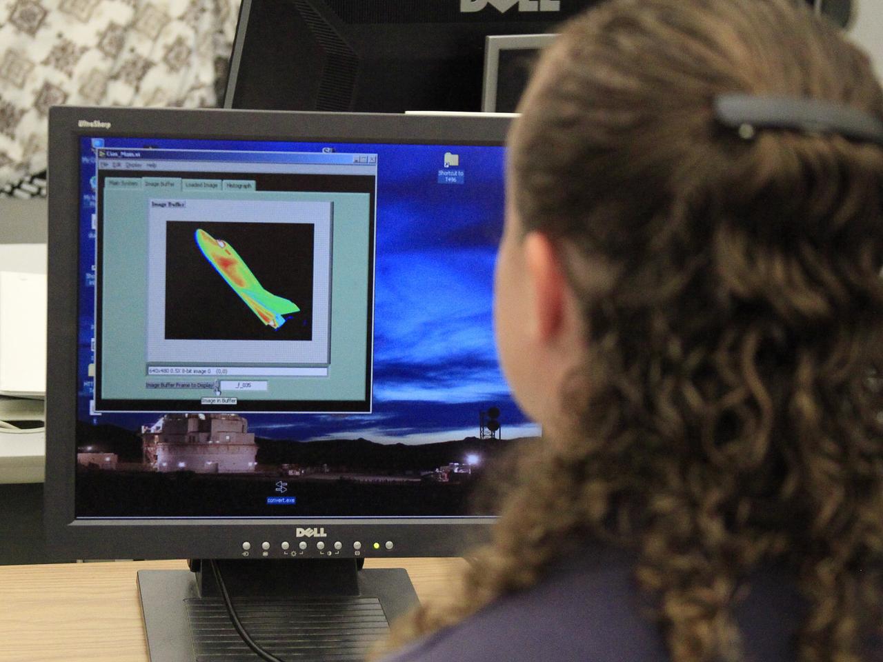
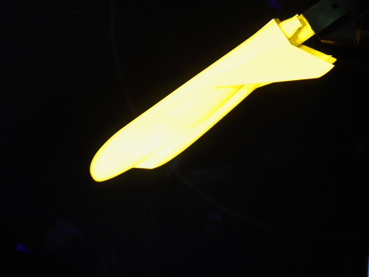
The HL-10 Lifting Body is seen here parked on Rogers Dry Lake, the unique location where it landed after research flights. This 1968 photo shows the vehicle after the fins were modified to remove instabilities encountered on the first flight. It involved a change to the shape of the leading edge of the fins to eliminate flow separation. It required extensive wind-tunnel testing at Langley Research Center, Hampton, Va. NASA Flight Research Center (FRC) engineer Bob Kempel than plotted thousands of data points by hand to come up with the modification, which involved a fiberglass glove backed with a metal structure on each fin's leading edge. This transformed the vehicle from a craft that was difficult to control into the best handling of the original group of lifting bodies at the FRC.

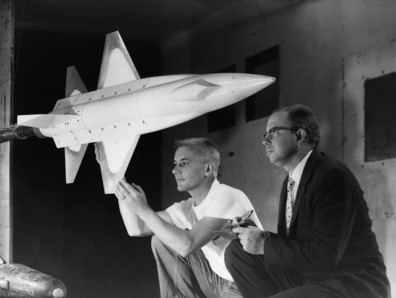
X-15 launch techniques were investigated using on-twentieth scale models mounted in the 7x10 FT Tunnel. -- Photograph published in Winds of Change, 75th Anniversary NASA publication (page 67), by James Schultz. -- Photograph also published in Sixty Years of Aeronautical Research 1917-1977 - a NASA publication (page 49), by David A. Anderton.
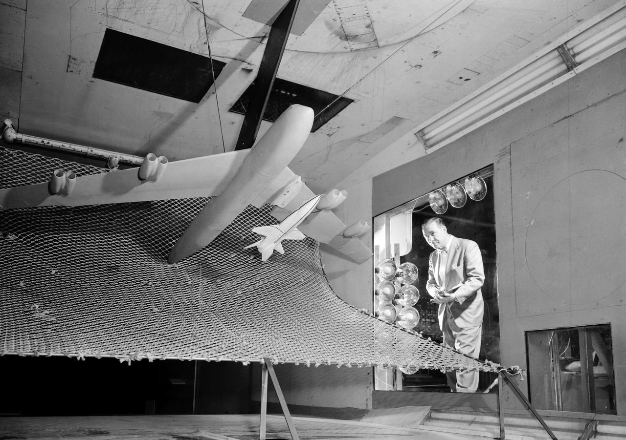
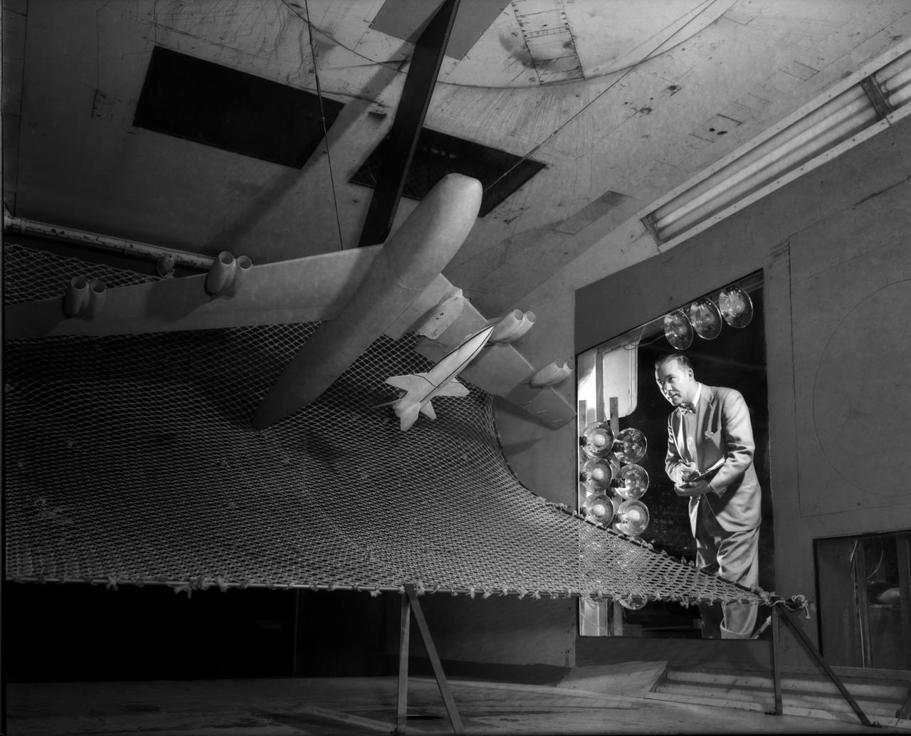
A one-twentieth scale model of the X-15 originally suspended beneath the wing of a B-52 is observed by a scientist of the National Aeronautics and Space Administration (NASA) as it leaves the bomber model in tests to determine the release characteristics and drop motion of the research airplane. Caption: The aerodynamics of air launching the North American X-15 being investigated in the 300MPH Low Speed 7x10 Tunnel, about 1957. Photograph published in Engineer in Charge: A History of the Langley Aeronautical Laboratory, 1917-1958 by James R. Hansen. Page 366. Photograph also published in Sixty Years of Aeronautical Research 1917-1977 By David A. Anderton. A NASA publication. Page 49.
A one-sixth scale model of the Mercury capsule being tested in the 300-mph 7 x 10-foot wind tunnel.
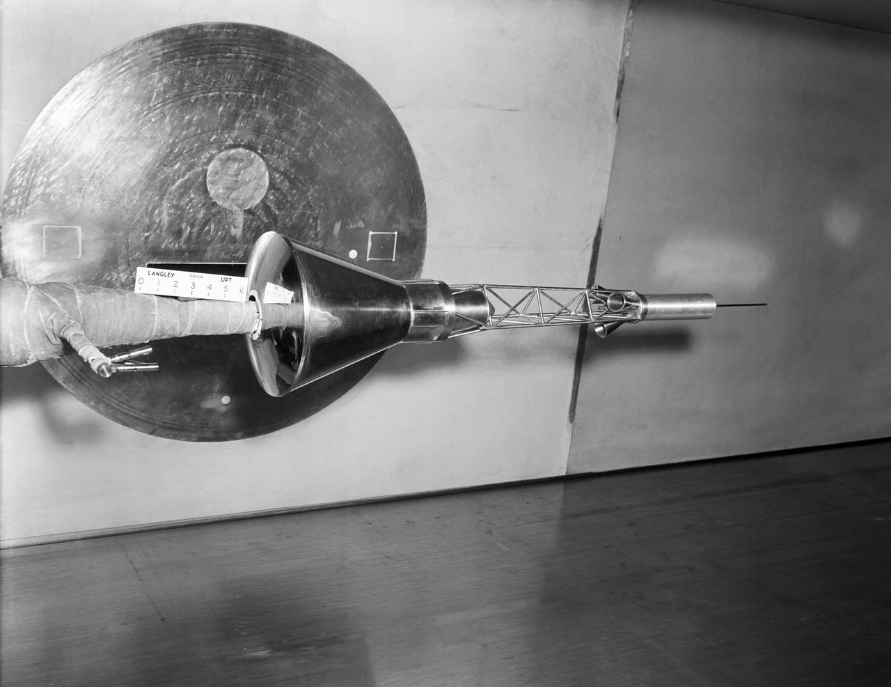
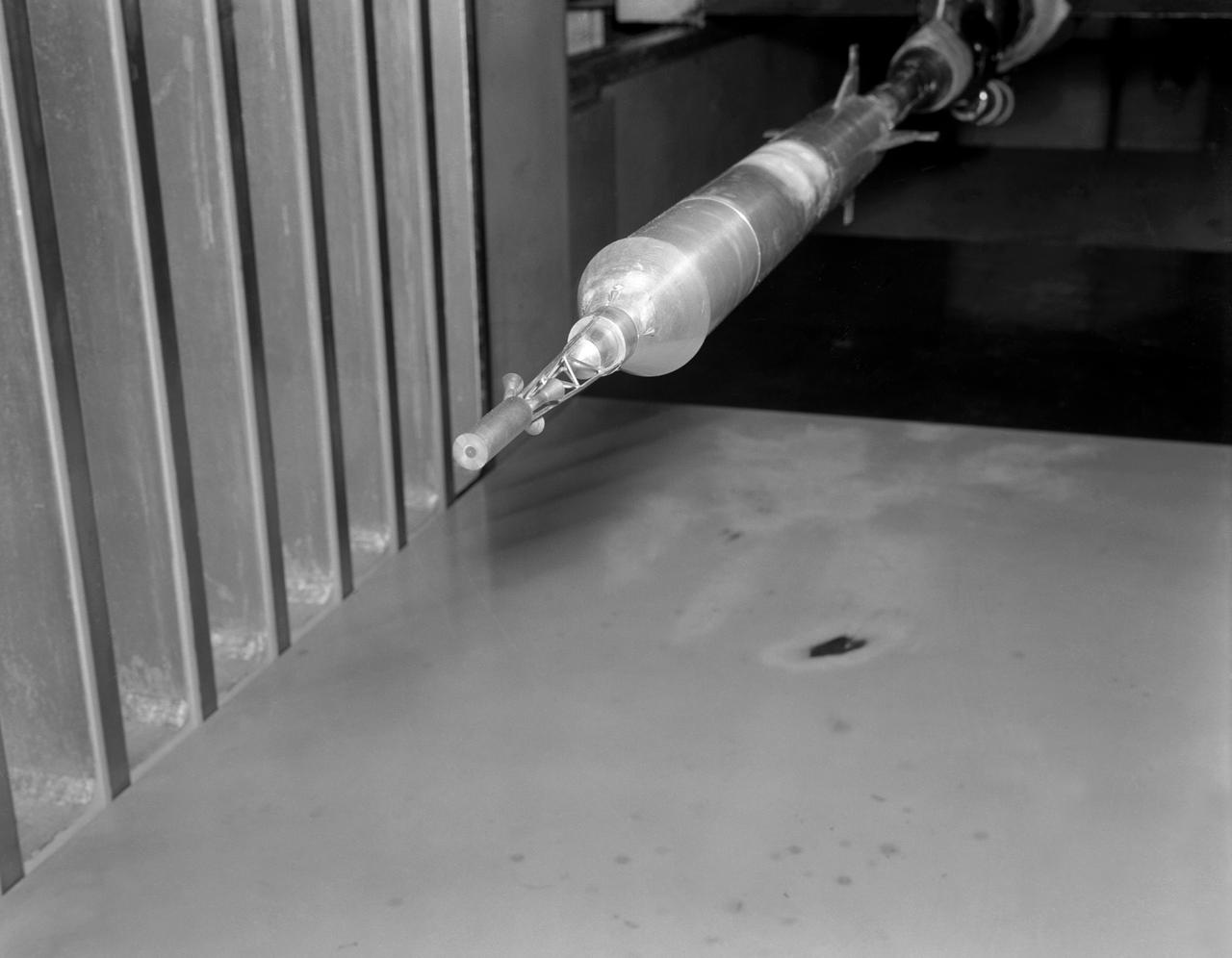
Model of Mercury (Redstone booster) carrying the spacecraft in the Unitary Plan wind tunnel for testing.
Model of Mercury being tested in the Unitary Plan Wind Tunnel.

Model of Mercury (Redstone booster) carrying the spacecraft in the Unitary Plan wind tunnel for testing.
Mercury capsule model (Pohlhamus).
A one-twentieth scale model of the X-15 originally suspended beneath the wing of a B-52 is observed by a scientist of the National Aeronautics and Space Administration (NASA) as it leaves the bomber model in tests to determine the release characteristics and drop motion of the research airplane. Caption: The aerodynamics of air launching the North American X-15 being investigated in the 300MPH Low Speed 7x10 Tunnel, about 1957. Photograph published in Engineer in Charge: A History of the Langley Aeronautical Laboratory, 1917-1958 by James R. Hansen. Page 366. Photograph also published in Sixty Years of Aeronautical Research 1917-1977 By David A. Anderton. A NASA publication. Page 49.
Mercury capsule in Spin Tunnel
Mercury capsule in Spin Tunnel
Gemini capsule being tested in Unitary Plan Wind Tunnel.
The Multi-Axis Space Test Inertial Facility (MASTIF) in the Altitude Wind Tunnel at the National Aeronautics and Space Administration (NASA) Lewis Research Center. Although the Mercury astronaut training and mission planning were handled by the Space Task Group at Langley Research Center, NASA Lewis played an important role in the program, beginning with the Big Joe launch. Big Joe was a singular attempt early in the program to use a full-scale Atlas booster and simulate the reentry of a mockup Mercury capsule without actually placing it in orbit. A unique three-axis gimbal rig was built inside Lewis’ Altitude Wind Tunnel to test Big Joe’s attitude controls. The control system was vital since the capsule would burn up on reentry if it were not positioned correctly. The mission was intended to assess the performance of the Atlas booster, the reliability of the capsule’s attitude control system and beryllium heat shield, and the capsule recovery process. The September 9, 1959 launch was a success for the control system and heatshield. Only a problem with the Atlas booster kept the mission from being a perfect success. The MASTIF was modified in late 1959 to train Project Mercury pilots to bring a spinning spacecraft under control. An astronaut was secured in a foam couch in the center of the rig. The rig then spun on three axes from 2 to 50 rotations per minute. Small nitrogen gas thrusters were used by the astronauts to bring the MASTIF under control.
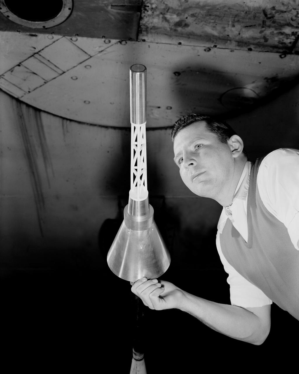
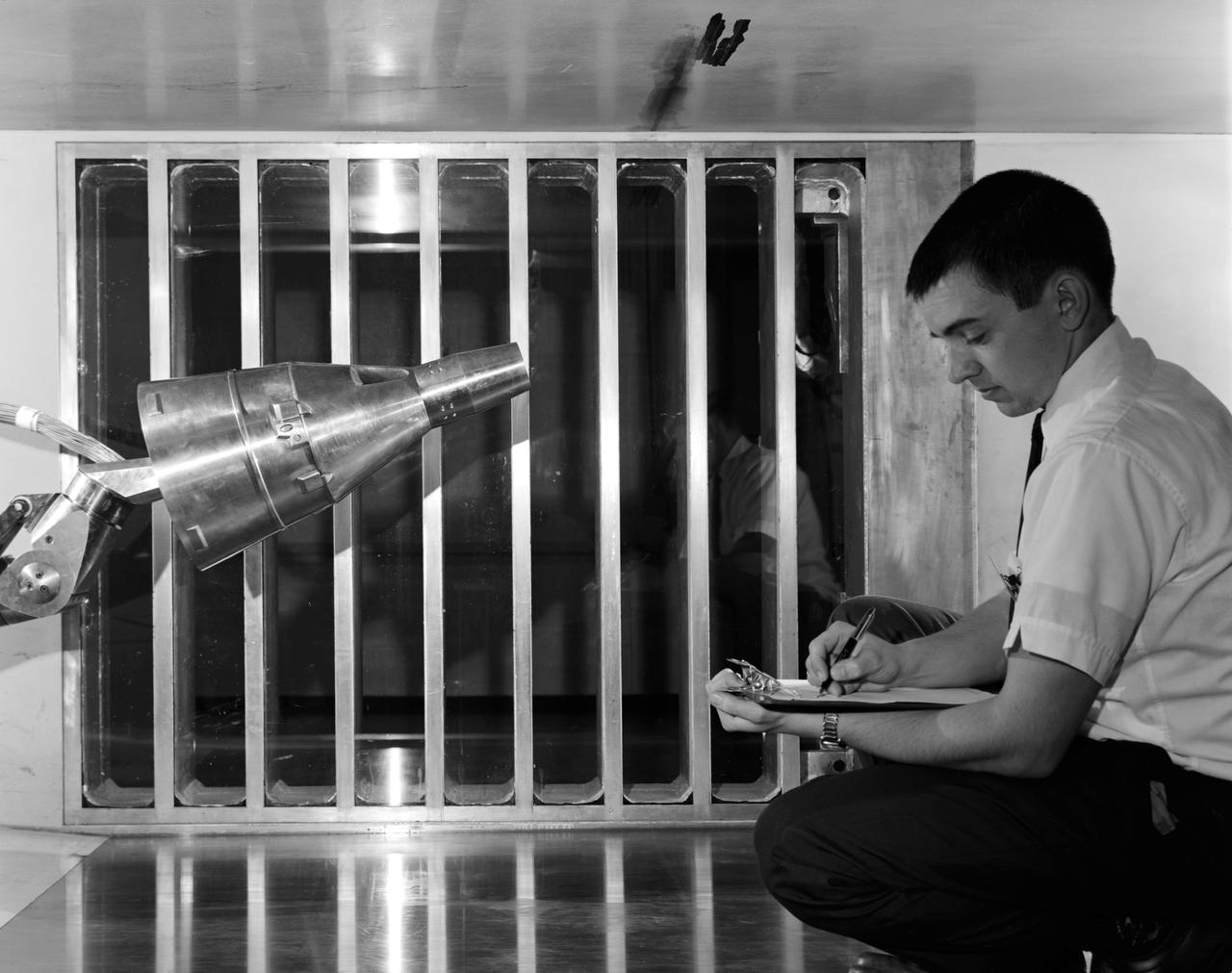
Researcher checks model of Project Fire Reentry package to be tested in Unitary Plan Wind Tunnel. Project FIRE (Flight Investigation Reentry Environment) studied the effects of reentry heating on spacecraft materials. It involved both wind tunnel and flight tests, although the majority were tests with Atlas rockets and recoverable reentry packages. These flight tests took place at Cape Canaveral in Florida. Wind tunnel tests were made in several Langley tunnels including the Unitary Plan Wind Tunnel, the 8-foot High-Temperature Tunnel and the 9x6-Foot Thermal Structures Tunnel. Photo published in book "A Century at Langley" by Joseph Chambers pg. 92
Research, Science, and Engineering Services (RSES) intern tour of the 8ft high temperature hypersonic wind tunnel (8ft HTT/B1265)
CRM-HL model (2.7% full span) installed in the National Transonic Facility (NTF)

This is the 3rd entry of the TTBW model in 14x22. This test specifically is a lateral-directional test looking at the effects of 3D printed ventral, keel, and dorsal strakes on the stability and control characteristics of the model. Cooperative agreement between Boeing and NASA.

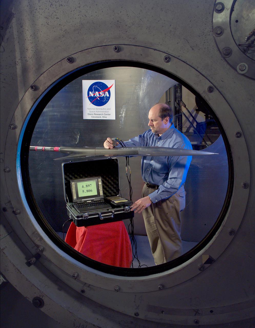
NASA Staff Dr.Darden, Matthew Overhold, Kathy Needleman, Robert Mack. Mach 3 Sonic Boom Model Wind Tunnel