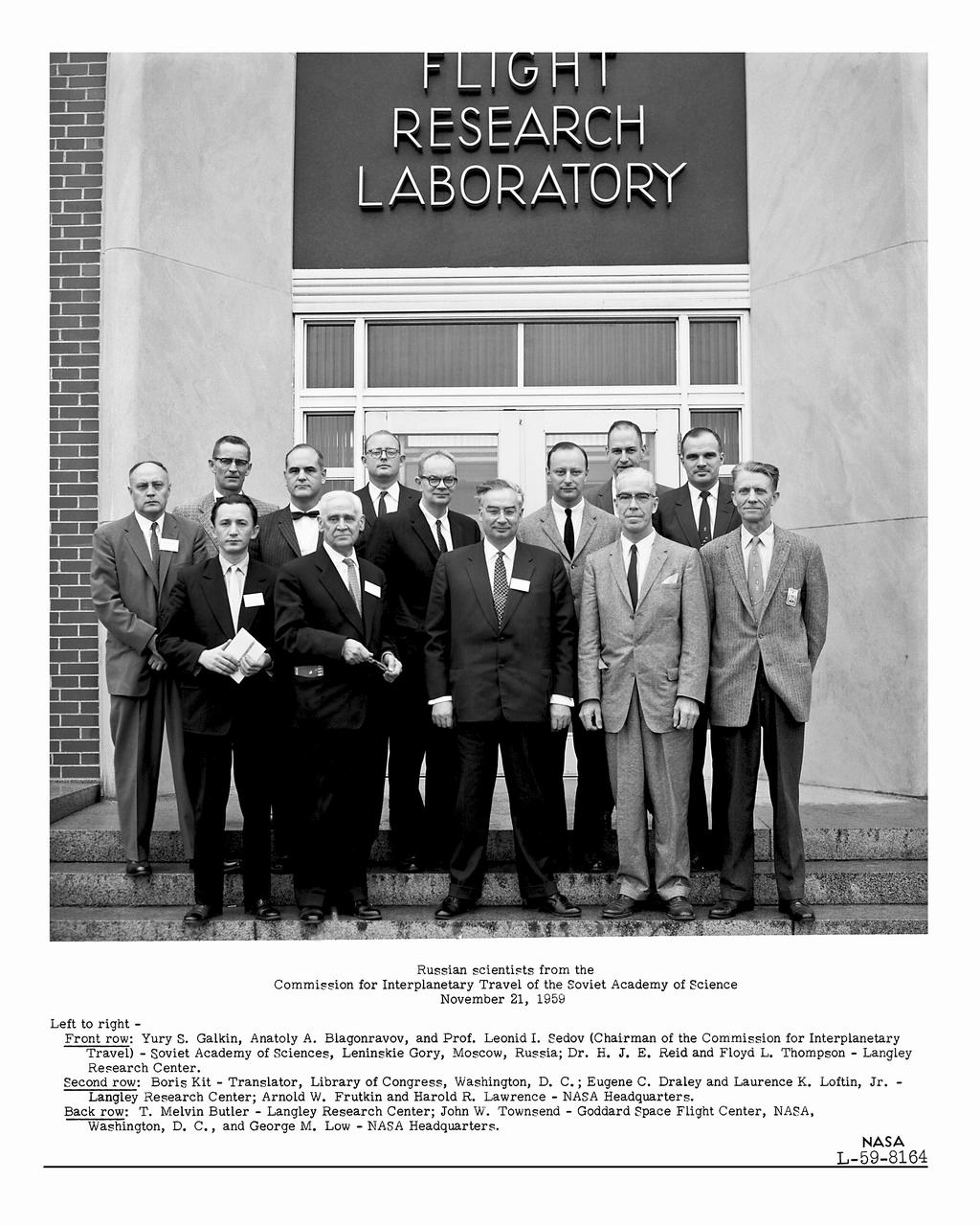
Russian Scientists from the Commission of Interplanetary Travel of the Soviet Academy of Science November 21,1959 Left to right: Front row: Yury S. Galkin, Anatoly A. Blagonravov, and Prof. Leonid I. Sedov (Chair of the Commission for Interplanetary Travel)-Soviet Academy of Science, Leninski Gory, Moscow, Russia Dr. H.J. E. Reid and Floyd L. Thompson Langley Research Center. Second row: Boris Kit Translator, Library of Congress, Washington, D.C. Eugene C. Draley and Laurence K. Loftin, Jr. -Langley Research Center Arnold W. Frutkin and Harold R. Lawrence NASA Headquarters. Back row: T.Melvin Butler-Langley Research Center John W. Townsend Goddard Space Flight Center, NASA, Washington D.C., and George M. Low NASA Headquarters.
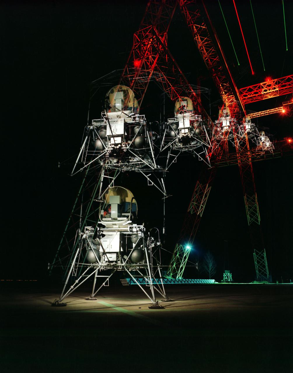
During a nighttime training session, a multiple exposure captures the movement of the Lunar Excursion Module Simulator (LEMS). The LEMS was a manned vehicle used to familiarize the Apollo astronauts with the handling characteristics of lunar-landing type vehicle. The Apollo Program is best known for the astronaut Neal Armstrong s first step on the Moon July 20, 1969. In its earliest test period, the LEMS featured a helicopter crew cabin atop the lunar landing module. Later, the helicopter crew cabin was replaced with a stand-up rectangular cabin which was more efficient for controlling maneuvers and for better viewing by the pilot. The vehicle was designed at Langley Research Center in Hampton, VA. This multiple exposure shows a simulated Moon landing of the (LEMS) trainer at Langley s Lunar Landing Research Facility. -- Photograph published in Winds of Change, 75th Anniversary NASA publication (page 70), by James Shultz. Also published in " A Century at Langley" by Joseph Chambers, pg. 93.
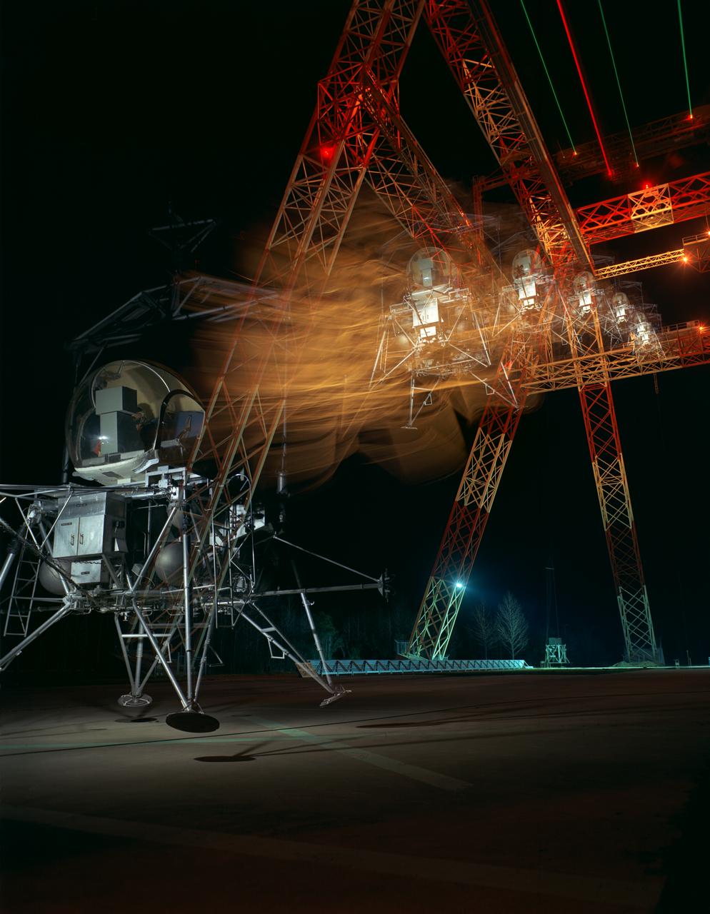
During a nighttime training session, a multiple exposure captures the movement of the Lunar Excursion Module Simulator (LEMS). The LEMS was a manned vehicle used to familiarize the Apollo astronauts with the handling characteristics of lunar-landing type vehicle. The Apollo Program is best known for the astronaut Neal Armstrong s first step on the Moon July 20, 1969. In its earliest test period, the LEMS featured a helicopter crew cabin atop the lunar landing module. Later, the helicopter crew cabin was replaced with a stand-up rectangular cabin which was more efficient for controlling maneuvers and for better viewing by the pilot. The vehicle was designed at Langley Research Center in Hampton, VA. This multiple exposure shows a simulated Moon landing of the (LEMS) trainer at Langley s Lunar Landing Research Facility. -- Photograph published in Winds of Change, 75th Anniversary NASA publication (page 70), by James Shultz. Also published in " A Century at Langley" by Joseph Chambers, pg. 93.
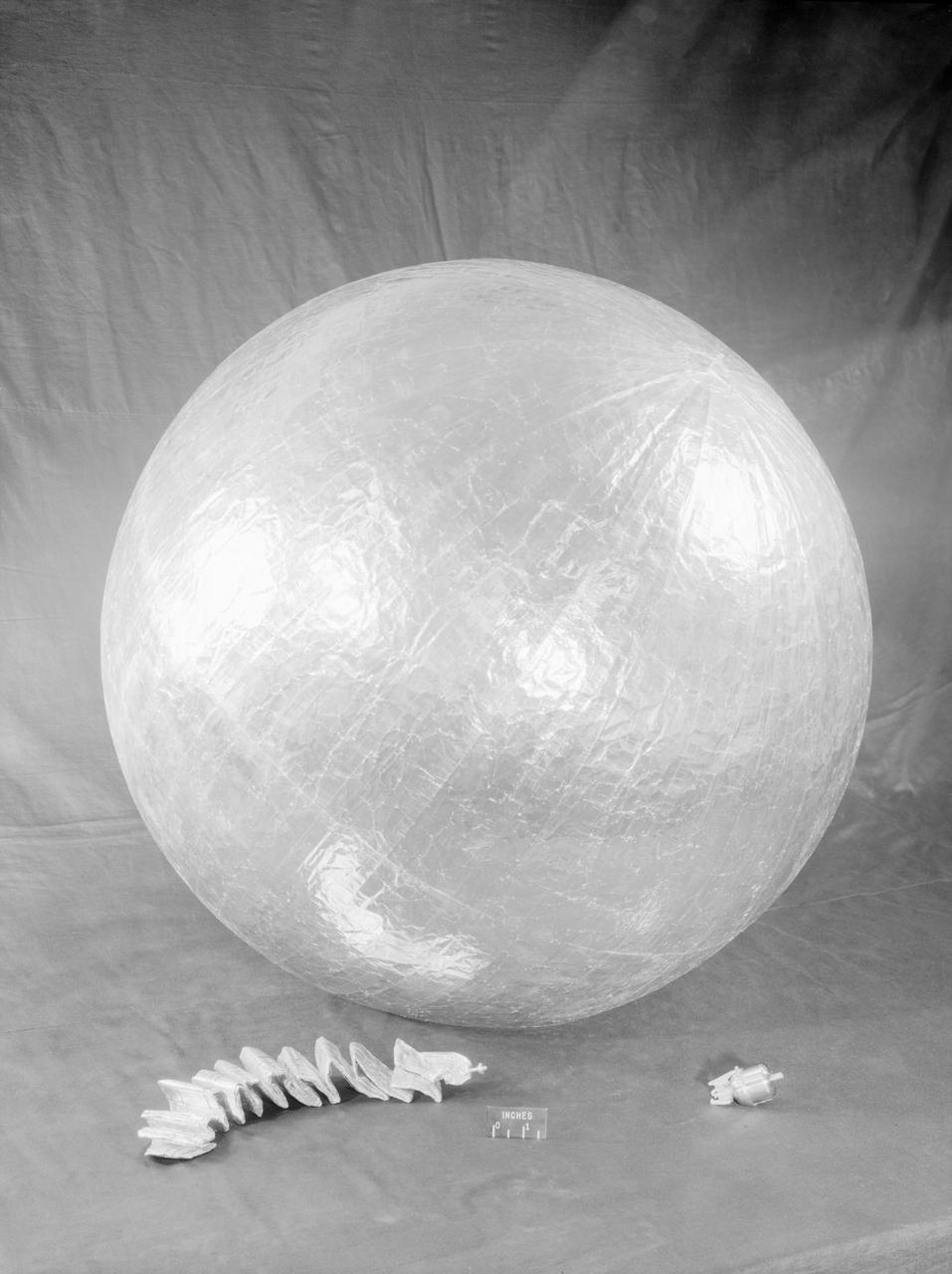
James Hansen describes the work on Project Echo s air density experiment known as the Sub-Satellite. Before launch engineers subjected the sub-satellite to many tests. Here, the sub-satellite is shown prior to tests to determine the capacity of the 30-inch Sub-Satellite to withstand the high temperature of direct sunlight in space, Langley researchers subjected it to 450 F heat test. Results indicated that the aluminum-covered Mylar plastic would effectively reflect the dangerous heat. -- Published in James R. Hansen, Spaceflight Revolution: NASA Langley Research Center From Sputnik to Apollo, NASA SP-4308, p. 168.
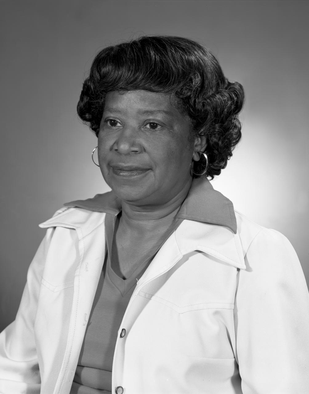
Portrait of Mary Jackson. 2017 Hall of Honor inductee. Langley Research Center NACA and NASA Hall of Honor. In honor and recognition of the ambition and motivation that enabled her career progression from human computer to NASA' s first African-American female engineer, and subsequent career supporting the hiring and promotion of other deserving female and minority employees.
Portrait of Mary Jackson. 2017 Hall of Honor inductee. Langley Research Center NACA and NASA Hall of Honor. In honor and recognition of the ambition and motivation that enabled her career progression from human computer to NASA' s first African-American female engineer, and subsequent career supporting the hiring and promotion of other deserving female and minority employees.
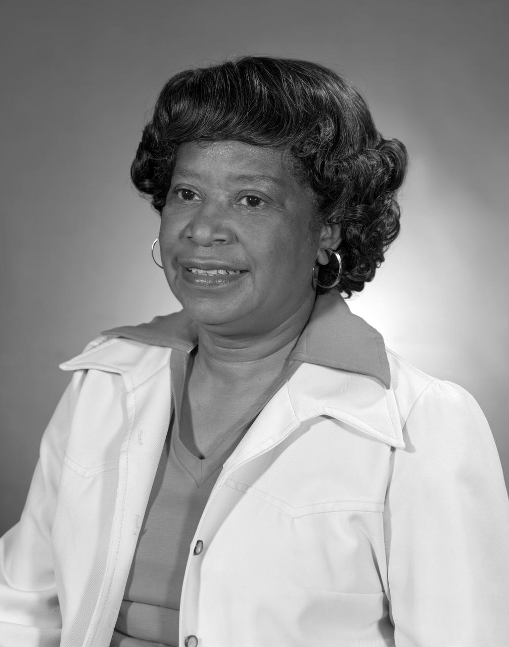
Portrait of Mary Jackson. 2017 Hall of Honor inductee. Langley Research Center NACA and NASA Hall of Honor. In honor and recognition of the ambition and motivation that enabled her career progression from human computer to NASA's s first African-American female engineer, and subsequent career supporting the hiring and promotion of other deserving female and minority employees.
Portrait of Mary Jackson. 2017 Hall of Honor inductee. Langley Research Center NACA and NASA Hall of Honor. In honor and recognition of the ambition and motivation that enabled her career progression from human computer to NASA' s first African-American female engineer, and subsequent career supporting the hiring and promotion of other deserving female and minority employees.
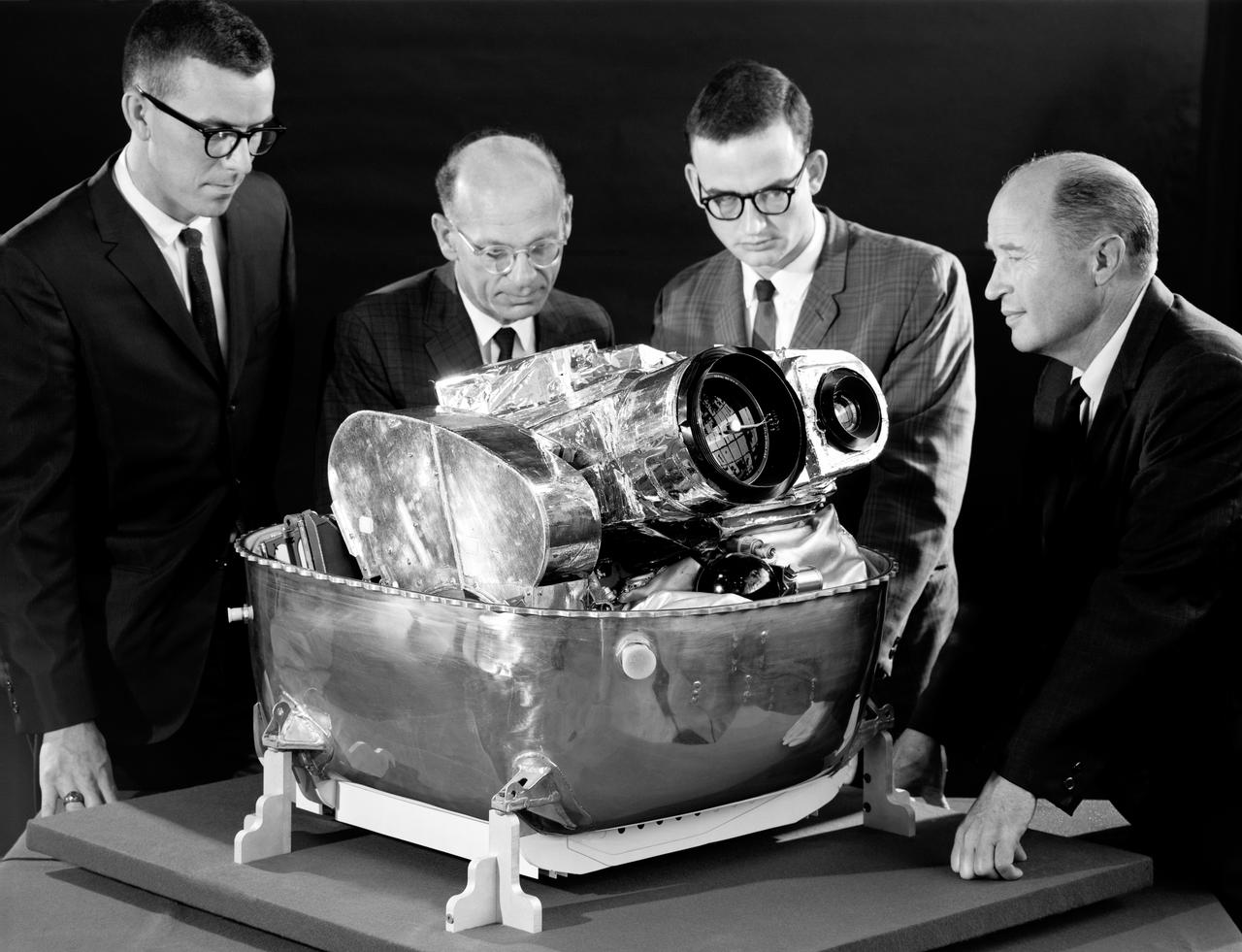
Lunar Orbiter was essentially a flying camera. The payload structure was built around a pressurized shell holding Eastman Kodak s dual-imaging photographic system, which used a camera with wide-angle and telephoto lenses that could simultaneously take two kinds of pictures on the same film. Men in in the picture are: Right to left Cliff Nelson, Calvin Broome, Israel Taback and Joe Mooreman. -- Published in James R. Hansen, Spaceflight Revolution: NASA Langley Research Center From Sputnik to Apollo, NASA SP-4308, p. 329.
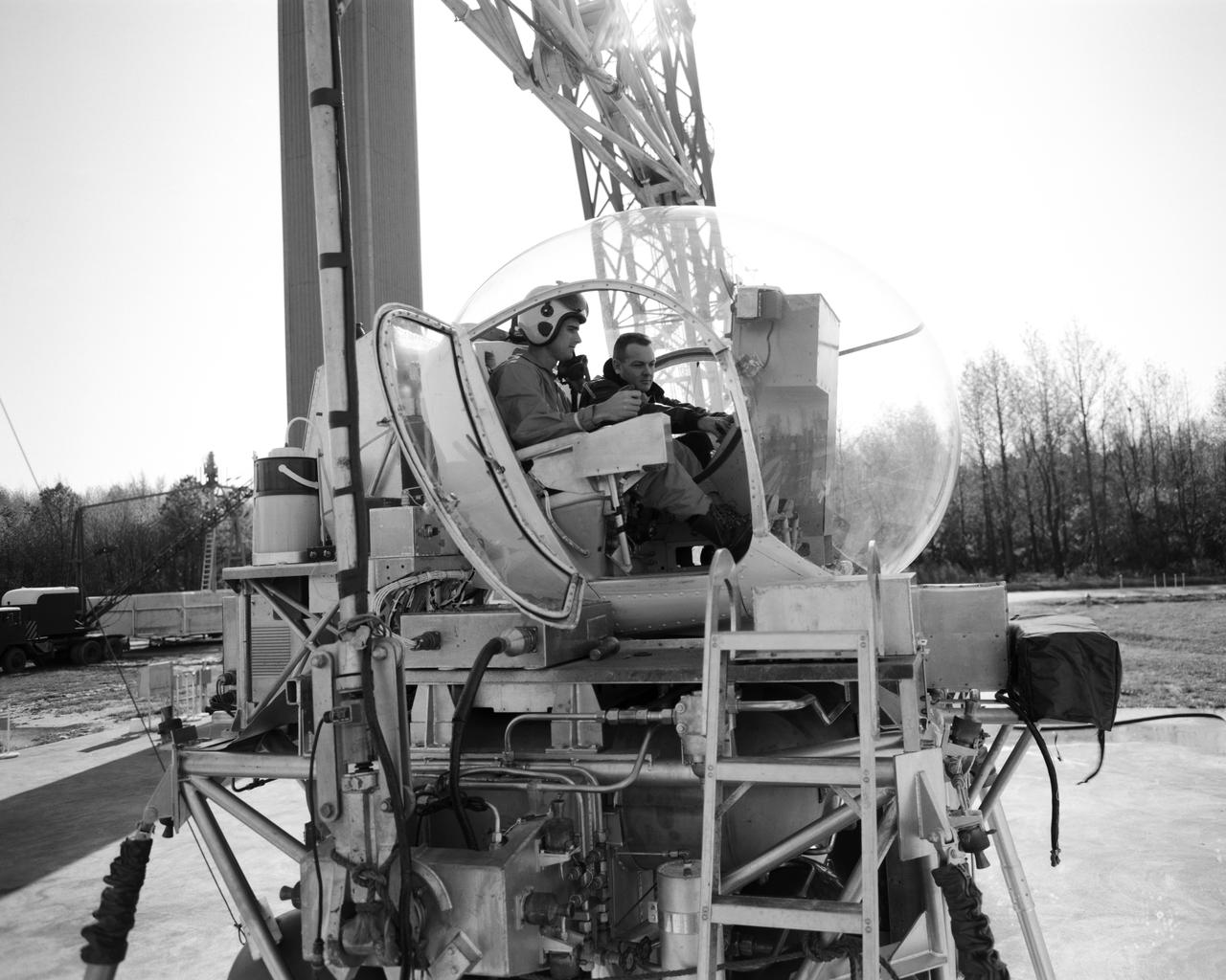
Lunar Landing Simulator: Astronaut Roger B. Chaffee (left) receives instruction from Maxwell W. Goode, a scientist at NASA s Langley Research Center. Goode is explaining the operation of the Lunar Landing Simulator at the Lunar Landing Research Facility. Chaffee was one of the third group of astronauts selected by NASA in October 1963. In addition to participating in the overall training program, he was also tasked with working on flight control communications systems, instrumentation systems, and attitude and translation control systems in the Apollo Branch of the Astronaut office. On March 21, 1966, he was selected as one of the pilots for the AS-204 mission, the first 3-man Apollo flight. Lieutenant Commander Chaffee died on January 27, 1967, in the Apollo spacecraft flash fire during a launch pad test at Kennedy Space Center, Florida.

NASA's Dryden Flight Research Center marked its 60th anniversary as the aerospace agency's lead center for atmospheric flight research and operations in 2006. In connection with that milestone, hundreds of the center's staff and retirees gathered in nearby Lancaster, Calif., in November 2006 to reflect on the center's challenges and celebrate its accomplishments over its six decades of advancing the state-of-the-art in aerospace technology. The center had its beginning in 1946 when a few engineers from the National Advisory Committee for Aeronautics' Langley Memorial Aeronautical Laboratory were detailed to Muroc Army Air Base (now Edwards Air Force Base) in Southern California's high desert to support the joint Army Air Force / NACA / Bell Aircraft XS-1 research airplane program. Since that inauspicious beginning, the center has been at the forefront of many of the advances in aerospace technology by validating advanced concepts through actual in-flight research and testing. Dryden is uniquely situated to take advantage of the excellent year-round flying weather, remote area, and visibility to test some of the nation�s most exciting aerospace vehicles. Today, NASA Dryden is NASA's premier flight research and test organization, continuing to push the envelope in the validation of high-risk aerospace technology and space exploration concepts, and in conducting airborne environmental and space science missions in the 21st century.

Project LOLA. Test subject sitting at the controls: Project LOLA or Lunar Orbit and Landing Approach was a simulator built at Langley to study problems related to landing on the lunar surface. It was a complex project that cost nearly 2 million dollars. James Hansen wrote: This simulator was designed to provide a pilot with a detailed visual encounter with the lunar surface the machine consisted primarily of a cockpit, a closed-circuit TV system, and four large murals or scale models representing portions of the lunar surface as seen from various altitudes. The pilot in the cockpit moved along a track past these murals which would accustom him to the visual cues for controlling a spacecraft in the vicinity of the moon. Unfortunately, such a simulation--although great fun and quite aesthetic--was not helpful because flight in lunar orbit posed no special problems other than the rendezvous with the LEM, which the device did not simulate. Not long after the end of Apollo, the expensive machine was dismantled. (p. 379) Ellis J. White wrote in his paper, Discussion of Three Typical Langley Research Center Simulation Programs : A typical mission would start with the first cart positioned on model 1 for the translunar approach and orbit establishment. After starting the descent, the second cart is readied on model 2 and, at the proper time, when superposition occurs, the pilot s scene is switched from model 1 to model 2. then cart 1 is moved to and readied on model 3. The procedure continues until an altitude of 150 feet is obtained. The cabin of the LM vehicle has four windows which represent a 45 degree field of view. The projection screens in front of each window represent 65 degrees which allows limited head motion before the edges of the display can be seen. The lunar scene is presented to the pilot by rear projection on the screens with four Schmidt television projectors. The attitude orientation of the vehicle is represented by changing the lunar scene through the portholes determined by the scan pattern of four orthicons. The stars are front projected onto the upper three screens with a four-axis starfield generation (starball) mounted over the cabin and there is a separate starball for the low window. -- Published in James R. Hansen, Spaceflight Revolution: NASA Langley Research Center From Sputnik to Apollo, (Washington: NASA, 1995), p. 379 Ellis J. White, Discussion of Three Typical Langley Research Center Simulation Programs, Paper presented at the Eastern Simulation Council (EAI s Princeton Computation Center), Princeton, NJ, October 20, 1966.
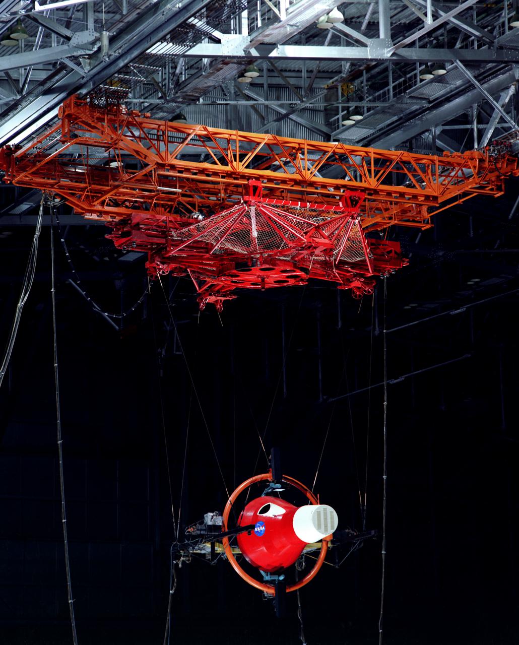
Gemini Rendezvous Docking Simulator suspended from the roof of the Langley Research Center s aircraft hangar. Francis B. Smith wrote: The rendezvous and docking operation of the Gemini spacecraft with the Agena and of the Apollo Command Module with the Lunar Excursion Module have been the subject of simulator studies for several years. This figure illustrates the Gemini-Agena rendezvous docking simulator at Langley. The Gemini spacecraft was supported in a gimbal system by an overhead crane and gantry arrangement which provided 6 degrees of freedom - roll, pitch, yaw, and translation in any direction - all controllable by the astronaut in the spacecraft. Here again the controls fed into a computer which in turn provided an input to the servos driving the spacecraft so that it responded to control motions in a manner which accurately simulated the Gemini spacecraft. -- Published in Barton C. Hacker and James M. Grimwood, On the Shoulders of Titans: A History of Project Gemini, NASA SP-4203 Francis B. Smith, Simulators for Manned Space Research, Paper presented at the 1966 IEEE International convention, March 21-25, 1966.
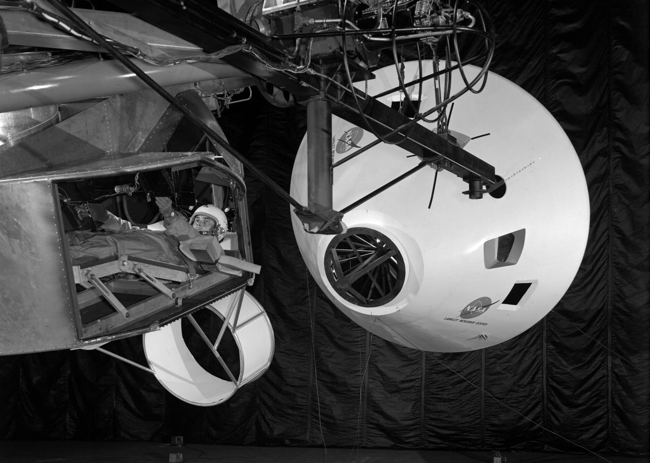
Originally the Rendezvous was used by the astronauts preparing for Gemini missions. The Rendezvous Docking Simulator was then modified and used to develop docking techniques for the Apollo program. The pilot is shown maneuvering the LEM into position for docking with a full-scale Apollo Command Module. From A.W. Vogeley, Piloted Space-Flight Simulation at Langley Research Center, Paper presented at the American Society of Mechanical Engineers, 1966 Winter Meeting, New York, NY, November 27 - December 1, 1966. The Rendezvous Docking Simulator and also the Lunar Landing Research Facility are both rather large moving-base simulators. It should be noted, however, that neither was built primarily because of its motion characteristics. The main reason they were built was to provide a realistic visual scene. A secondary reason was that they would provide correct angular motion cues (important in control of vehicle short-period motions) even though the linear acceleration cues would be incorrect. Apollo Rendezvous Docking Simulator: Langley s Rendezvous Docking Simulator was developed by NASA scientists to study the complex task of docking the Lunar Excursion Module with the Command Module in Lunar orbit.
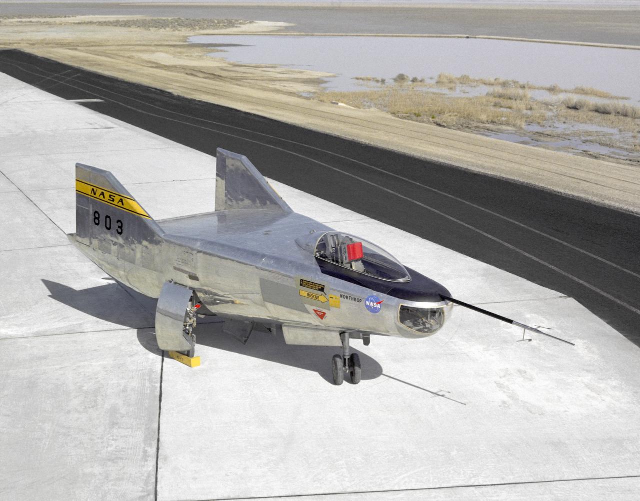
The M2-F2 Lifting Body is seen here on the ramp at the NASA Dryden Flight Research Center. The success of Dryden's M2-F1 program led to NASA's development and construction of two heavyweight lifting bodies based on studies at NASA's Ames and Langley research centers -- the M2-F2 and the HL-10, both built by the Northrop Corporation. The "M" refers to "manned" and "F" refers to "flight" version. "HL" comes from "horizontal landing" and 10 is for the tenth lifting body model to be investigated by Langley. The first flight of the M2-F2 -- which looked much like the "F1" -- was on July 12, 1966. Milt Thompson was the pilot. By then, the same B-52 used to air launch the famed X-15 rocket research aircraft was modified to also carry the lifting bodies. Thompson was dropped from the B-52's wing pylon mount at an altitude of 45,000 feet on that maiden glide flight. The M2-F2 weighed 4,620 pounds, was 22 feet long, and had a width of about 10 feet. On May 10, 1967, during the sixteenth glide flight leading up to powered flight, a landing accident severely damaged the vehicle and seriously injured the NASA pilot, Bruce Peterson. NASA pilots and researchers realized the M2-F2 had lateral control problems, even though it had a stability augmentation control system. When the M2-F2 was rebuilt at Dryden and redesignated the M2-F3, it was modified with an additional third vertical fin -- centered between the tip fins -- to improve control characteristics. The M2-F2/F3 was the first of the heavy-weight, entry-configuration lifting bodies. Its successful development as a research test vehicle answered many of the generic questions about these vehicles. NASA donated the M2-F3 vehicle to the Smithsonian Institute in December 1973. It is currently hanging in the Air and Space Museum along with the X-15 aircraft number 1, which was its hangar partner at Dryden from 1965 to 1969.
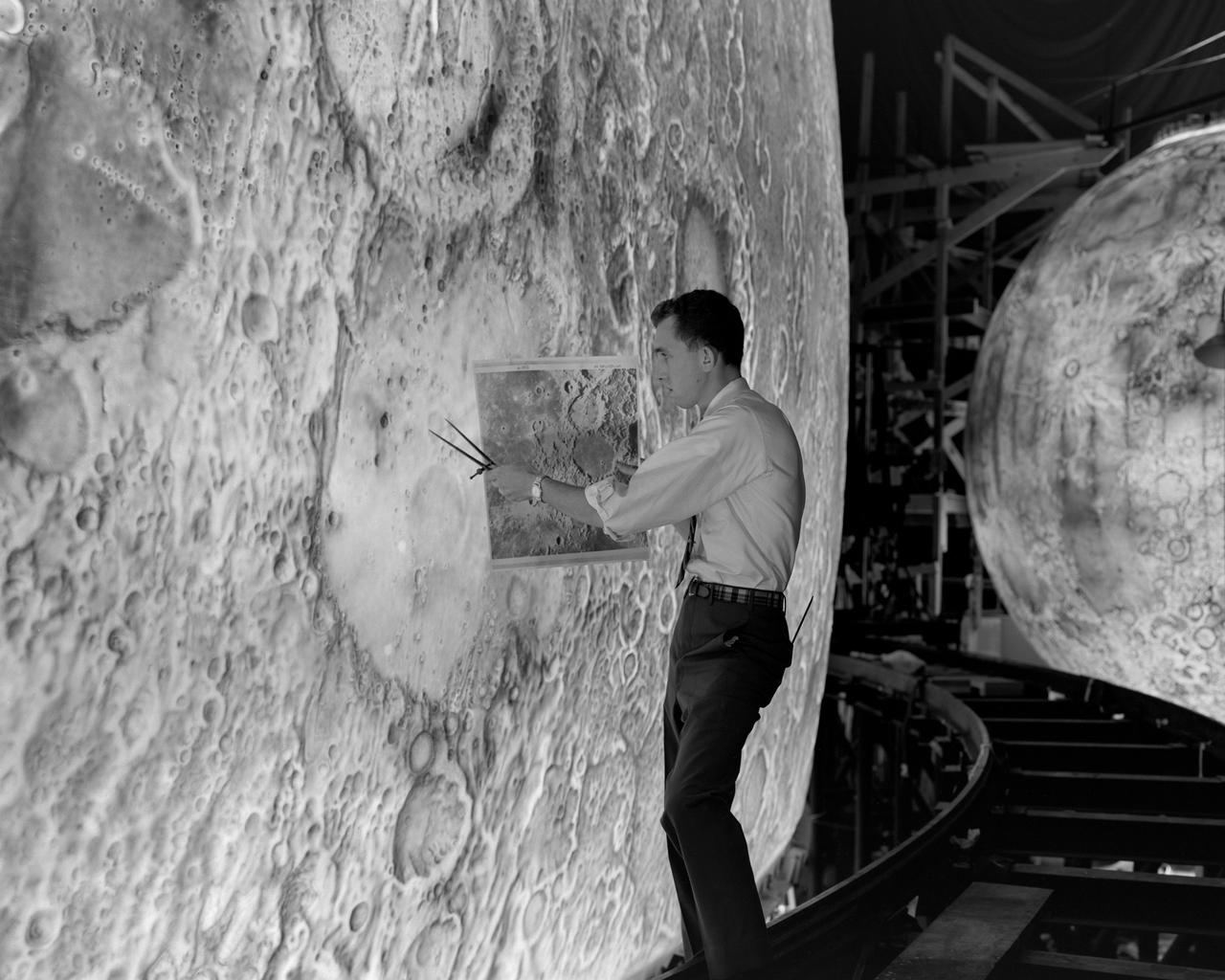
Artists used paintbrushes and airbrushes to recreate the lunar surface on each of the four models comprising the LOLA simulator. Project LOLA or Lunar Orbit and Landing Approach was a simulator built at Langley to study problems related to landing on the lunar surface. It was a complex project that cost nearly 2 million dollars. James Hansen wrote: This simulator was designed to provide a pilot with a detailed visual encounter with the lunar surface the machine consisted primarily of a cockpit, a closed-circuit TV system, and four large murals or scale models representing portions of the lunar surface as seen from various altitudes. The pilot in the cockpit moved along a track past these murals which would accustom him to the visual cues for controlling a spacecraft in the vicinity of the moon. Unfortunately, such a simulation--although great fun and quite aesthetic--was not helpful because flight in lunar orbit posed no special problems other than the rendezvous with the LEM, which the device did not simulate. Not long after the end of Apollo, the expensive machine was dismantled. (p. 379) Ellis J. White described the simulator as follows: Model 1 is a 20-foot-diameter sphere mounted on a rotating base and is scaled 1 in. 9 miles. Models 2,3, and 4 are approximately 15x40 feet scaled sections of model 1. Model 4 is a scaled-up section of the Crater Alphonsus and the scale is 1 in. 200 feet. All models are in full relief except the sphere. -- Published in James R. Hansen, Spaceflight Revolution: NASA Langley Research Center From Sputnik to Apollo, (Washington: NASA, 1995), p. 379 Ellis J. White, Discussion of Three Typical Langley Research Center Simulation Programs, Paper presented at the Eastern Simulation Council (EAI s Princeton Computation Center), Princeton, NJ, October 20, 1966.
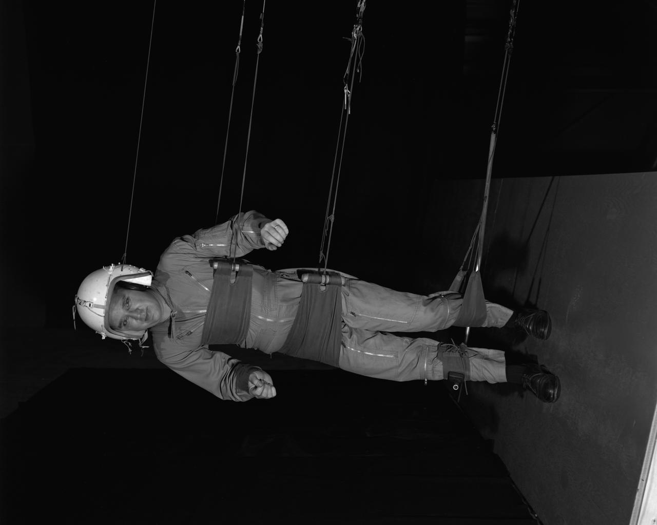
Reduced Gravity Walking Simulator located in the hangar at Langley Research Center. The initial version of this simulator was located inside the hangar. Later a larger version would be located at the Lunar Landing Facility. The purpose of this simulator was to study the subject while walking, jumping or running. Researchers conducted studies of various factors such as fatigue limit, energy expenditure, and speed of locomotion. A.W. Vigil wrote in his paper Discussion of Existing and Planned Simulators for Space Research, When the astronauts land on the moon they will be in an unfamiliar environment involving, particularly, a gravitational field only one-sixth as strong as on earth. A novel method of simulating lunar gravity has been developed and is supported by a puppet-type suspension system at the end of a long pendulum. A floor is provided at the proper angle so that one-sixth of the subject' s weight is supported by the floor with the remainder being supported by the suspension system. This simulator allows almost complete freedom in vertical translation and pitch and is considered to be a very realistic simulation of the lunar walking problem. For this problem this simulator suffers only slightly from the restrictions in lateral movement it puts on the test subject. This is not considered a strong disadvantage for ordinary walking problems since most of the motions do, in fact, occur in the vertical plane. However, this simulation technique would be severely restrictive if applied to the study of the extra-vehicular locomotion problem, for example, because in this situation complete six degrees of freedom are rather necessary. This technique, in effect, automatically introduces a two-axis attitude stabilization system into the problem. The technique could, however, be used in preliminary studies of extra-vehicular locomotion where, for example, it might be assumed that one axis of the attitude control system on the astronaut maneuvering unit may have failed. -- Published in James R. Hansen, Spaceflight Revolution: NASA Langley Research Center From Sputnik to Apollo, NASA SP-4308, p. 377 A.W. Vigil, Discussion of Existing and Planned Simulators for Space Research, Paper presented at Conference on the Role of Simulation in Space Technology, Blacksburg, VA, August 17-21, 1964.
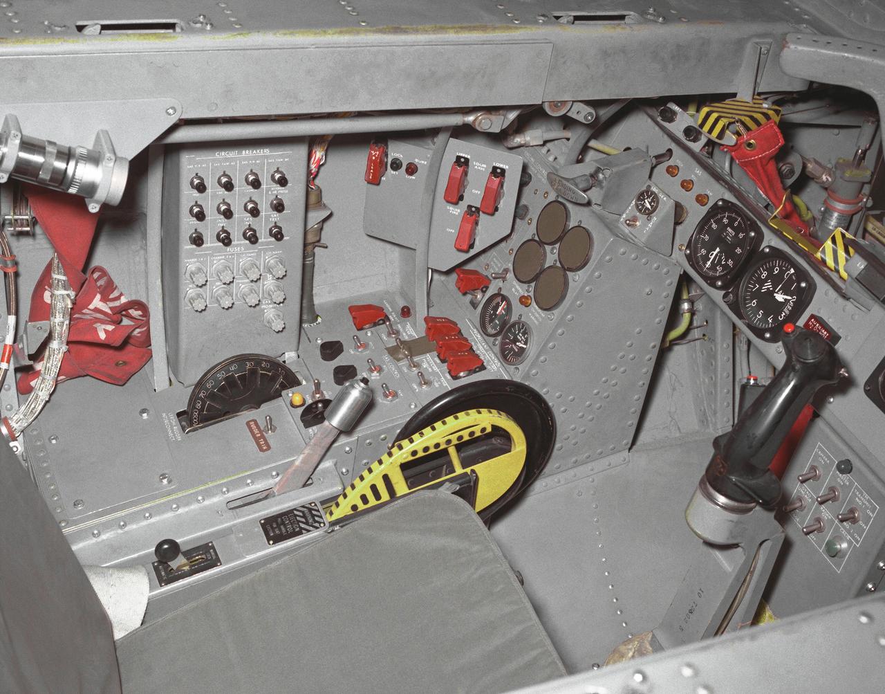
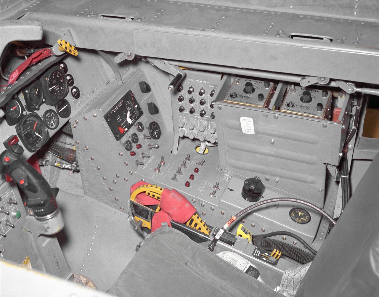
This photo shows the left side cockpit instrumentation panel of the M2-F2 Lifting Body. The success of Dryden's M2-F1 program led to NASA's development and construction of two heavyweight lifting bodies based on studies at NASA's Ames and Langley research centers -- the M2-F2 and the HL-10, both built by the Northrop Corporation. The "M" refers to "manned" and "F" refers to "flight" version. "HL" comes from "horizontal landing" and 10 is for the tenth lifting body model to be investigated by Langley. The first flight of the M2-F2 -- which looked much like the "F1" -- was on July 12, 1966. Milt Thompson was the pilot. By then, the same B-52 used to air launch the famed X-15 rocket research aircraft was modified to also carry the lifting bodies. Thompson was dropped from the B-52's wing pylon mount at an altitude of 45,000 feet on that maiden glide flight. The M2-F2 weighed 4,620 pounds, was 22 feet long, and had a width of about 10 feet. On May 10, 1967, during the sixteenth glide flight leading up to powered flight, a landing accident severely damaged the vehicle and seriously injured the NASA pilot, Bruce Peterson. NASA pilots and researchers realized the M2-F2 had lateral control problems, even though it had a stability augmentation control system. When the M2-F2 was rebuilt at Dryden and redesignated the M2-F3, it was modified with an additional third vertical fin -- centered between the tip fins -- to improve control characteristics. The M2-F2/F3 was the first of the heavy-weight, entry-configuration lifting bodies. Its successful development as a research test vehicle answered many of the generic questions about these vehicles. NASA donated the M2-F3 vehicle to the Smithsonian Institute in December 1973. It is currently hanging in the Air and Space Museum along with the X-15 aircraft number 1, which was its hangar partner at Dryden from 1965 to 1969.
This photo shows the right side cockpit instrumentation panel of the M2-F2 Lifting Body. The success of Dryden's M2-F1 program led to NASA's development and construction of two heavyweight lifting bodies based on studies at NASA's Ames and Langley research centers -- the M2-F2 and the HL-10, both built by the Northrop Corporation. The "M" refers to "manned" and "F" refers to "flight" version. "HL" comes from "horizontal landing" and 10 is for the tenth lifting body model to be investigated by Langley. The first flight of the M2-F2 -- which looked much like the "F1" -- was on July 12, 1966. Milt Thompson was the pilot. By then, the same B-52 used to air launch the famed X-15 rocket research aircraft was modified to also carry the lifting bodies. Thompson was dropped from the B-52's wing pylon mount at an altitude of 45,000 feet on that maiden glide flight. The M2-F2 weighed 4,620 pounds, was 22 feet long, and had a width of about 10 feet. On May 10, 1967, during the sixteenth glide flight leading up to powered flight, a landing accident severely damaged the vehicle and seriously injured the NASA pilot, Bruce Peterson. NASA pilots and researchers realized the M2-F2 had lateral control problems, even though it had a stability augmentation control system. When the M2-F2 was rebuilt at Dryden and redesignated the M2-F3, it was modified with an additional third vertical fin -- centered between the tip fins -- to improve control characteristics. The M2-F2/F3 was the first of the heavy-weight, entry-configuration lifting bodies. Its successful development as a research test vehicle answered many of the generic questions about these vehicles. NASA donated the M2-F3 vehicle to the Smithsonian Institute in December 1973. It is currently hanging in the Air and Space Museum along with the X-15 aircraft number 1, which was its hangar partner at Dryden from 1965 to 1969.
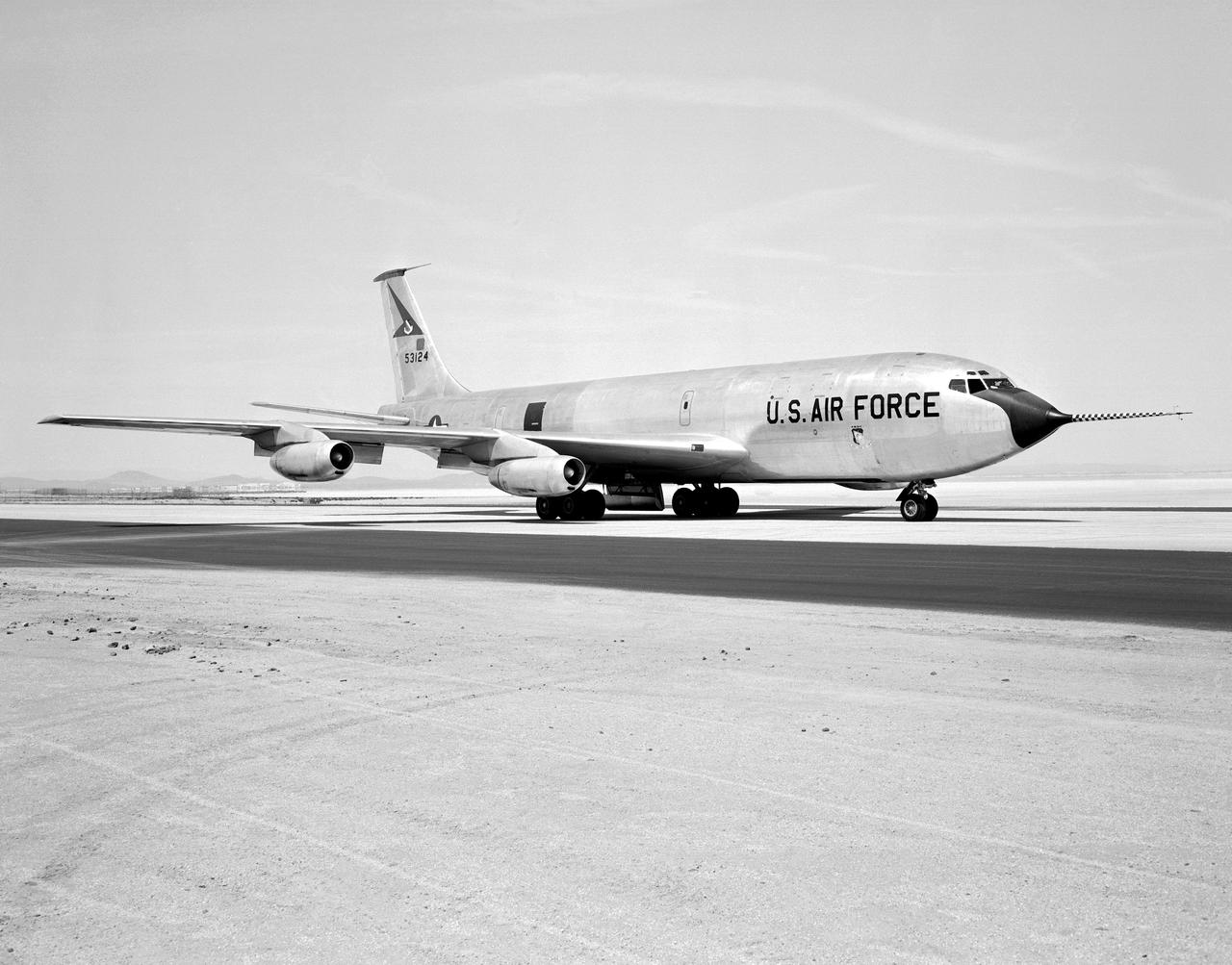
The Boeing KC-135 Stratotanker, besides being used extensively in its primary role as an inflight aircraft refueler, has assisted in several projects at the NASA Dryden Flight Research Center, Edwards, California. In 1957 and 1958, Dryden was asked by what was then the Civil Aeronautics Administration (later absorbed into the Federal Aviation Administration (FAA) in 1958) to help establish new approach procedure guidelines on cloud-ceiling and visibility minimums for Boeing's first jet airliner, the B-707. Dryden used a KC-135 (the military variant of the 707), seen here on the runway at Edwards Air Force Base, to aid the CAA in these tests. In 1979 and 1980, Dryden was again involved with general aviation research with the KC-135. This time, a special wingtip "winglet", developed by Richard Whitcomb of Langley Research Center, was tested on the jet aircraft. Winglets are small, nearly vertical fins installed on an airplane's wing tips to help produce a forward thrust in the vortices that typically swirl off the end of the wing, thereby reducing drag. This winglet idea was tested at the Dryden Flight Research Center on a KC-135A tanker loaned to NASA by the Air Force. The research showed that the winglets could increase an aircraft's range by as much as 7 percent at cruise speeds. The first application of NASA's winglet technology in industry was in general aviation business jets, but winglets are now being incorporated into most new commercial and military transport jets, including the Gulfstream III and IV business jets, the Boeing 747-400 and MD-11 airliners, and the C-17 military transport. In the 1980's, a KC-135 was used in support of the Space Shuttle program. Since the Shuttle was to be launched from Florida, researchers wanted to test the effect of rain on the sensitive thermal tiles. Tiles were mounted on special fixtures on an F-104 aircraft and a P-3 Orion. The F-104 was flown in actual rain conditions, and also behind the KC-135 spray tanker as it rel
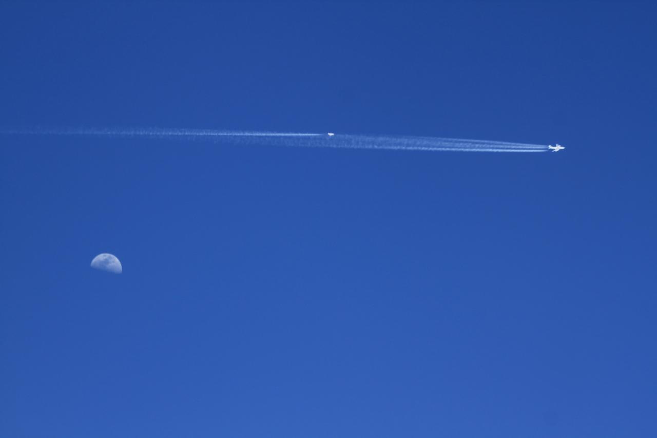
There’s more than one way to study the impact of biofuels. For NASA scientists, it means trailing an aircraft from as little as 300 feet behind while flying 34,000 feet in the air. Earlier this year, a NASA-led team conducted a series of carefully choreographed flights over California in order to sniff out how aircraft emissions differ when using petroleum fuels or biofuels. Early results from the Alternative Fuel Effects on Contrails and Cruise Emissions (ACCESS II) experiment confirm that blended biofuel is the cleaner-burning fuel. "Our findings show we definitely see a 50 percent reduction in soot emissions from the DC-8 when it burns the blended fuel as opposed to jet fuel alone," said Bruce Anderson, ACCESS principal investigator from NASA's Langley Research Center. The DC-8 is a NASA science workhorse: a flying laboratory equipped to collect—or, in this case, produce—data for basic Earth science research. During the ACESS experiment, scientists took advantage of the aircraft's segregated fuel tank. On the fly, the pilot switched the fuel type sent to each of the four engines. The engines burned either jet fuel, or a 50-50 blend of jet fuel and a renewable alternative produced from camelina plant oil. With each change of fuel, three other instrumented aircraft took turns lining up in the DC-8's wake and flying anywhere from 90 meters (300 feet) to more than 30 kilometers (20 miles) behind to catch a sniff. Richard Moore, a post-doctoral fellow at NASA Langley, took this photograph with a DSLR camera on May 7, 2014, during an ACCESS II test flight over Edwards Air Force Base in California. The photo was taken from Langley's HU-25C Guardian jet as it descended toward NASA's Armstrong Flight Research Center after a successful three-hour sampling flight behind the DC-8. The aircraft trailing the DC-8 in the photo was a Falcon 20-E5 jet owned by the German Aerospace Center. The flight on May 7 was just the first in a series of flights that lasted throughout the month. After the campaign, researchers continued to examine the data to determine whether a reduction in soot emissions translates to a reduction in contrail formation, and how that might affect climate. Read more: <a href="http://1.usa.gov/1wBfaKq" rel="nofollow">1.usa.gov/1wBfaKq</a> <b><a href="http://www.nasa.gov/audience/formedia/features/MP_Photo_Guidelines.html" rel="nofollow">NASA image use policy.</a></b> <b><a href="http://www.nasa.gov/centers/goddard/home/index.html" rel="nofollow">NASA Goddard Space Flight Center</a></b> enables NASA’s mission through four scientific endeavors: Earth Science, Heliophysics, Solar System Exploration, and Astrophysics. Goddard plays a leading role in NASA’s accomplishments by contributing compelling scientific knowledge to advance the Agency’s mission. <b>Follow us on <a href="http://twitter.com/NASAGoddardPix" rel="nofollow">Twitter</a></b> <b>Like us on <a href="http://www.facebook.com/pages/Greenbelt-MD/NASA-Goddard/395013845897?ref=tsd" rel="nofollow">Facebook</a></b> <b>Find us on <a href="http://instagram.com/nasagoddard?vm=grid" rel="nofollow">Instagram</a></b>

Heimdal Glacier in southern Greenland, in an image captured on Oct. 13, 2015, from NASA Langley Research Center's Falcon 20 aircraft flying 33,000 feet above mean sea level. NASA’s Operation IceBridge, an airborne survey of polar ice, recently finalized two overlapping campaigns at both of Earth’s poles. Down south, the mission observed a big drop in the height of two glaciers situated in the Antarctic Peninsula, while in the north it collected much needed measurements of the status of land and sea ice at the end of the Arctic summer melt season. This was the first time in its seven years of operations that IceBridge carried out parallel flights in the Arctic and Antarctic. Every year, the mission flies to the Arctic in the spring and to Antarctica in the fall to keep collect an uninterrupted record of yearly changes in the height of polar ice. Read more: <a href="http://www.nasa.gov/feature/goddard/nasa-s-operation-icebridge-completes-twin-polar-campaigns" rel="nofollow">www.nasa.gov/feature/goddard/nasa-s-operation-icebridge-c...</a> Credits: NASA/Goddard/John Sonntag <b><a href="http://www.nasa.gov/audience/formedia/features/MP_Photo_Guidelines.html" rel="nofollow">NASA image use policy.</a></b> <b><a href="http://www.nasa.gov/centers/goddard/home/index.html" rel="nofollow">NASA Goddard Space Flight Center</a></b> enables NASA’s mission through four scientific endeavors: Earth Science, Heliophysics, Solar System Exploration, and Astrophysics. Goddard plays a leading role in NASA’s accomplishments by contributing compelling scientific knowledge to advance the Agency’s mission. <b>Follow us on <a href="http://twitter.com/NASAGoddardPix" rel="nofollow">Twitter</a></b> <b>Like us on <a href="http://www.facebook.com/pages/Greenbelt-MD/NASA-Goddard/395013845897?ref=tsd" rel="nofollow">Facebook</a></b> <b>Find us on <a href="http://instagrid.me/nasagoddard/?vm=grid" rel="nofollow">Instagram</a></b>
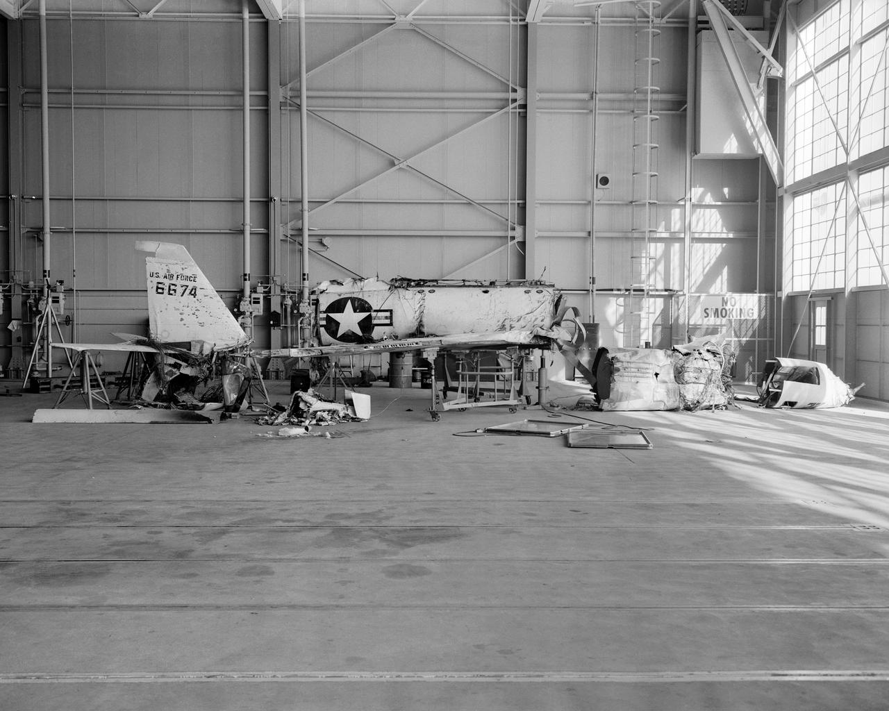
The X-2, initially an Air Force program, was scheduled to be transferred to the civilian National Advisory Committee for Aeronautics (NACA) for scientific research. The Air Force delayed turning the aircraft over to the NACA in the hope of attaining Mach 3 in the airplane. The service requested and received a two-month extension to qualify another Air Force test pilot, Capt. Miburn "Mel" Apt, in the X-2 and attempt to exceed Mach 3. After several ground briefings in the simulator, Apt (with no previous rocket plane experience) made his flight on 27 September 1956. Apt raced away from the B-50 under full power, quickly outdistancing the F-100 chase planes. At high altitude, he nosed over, accelerating rapidly. The X-2 reached Mach 3.2 (2,094 mph) at 65,000 feet. Apt became the first man to fly more than three times the speed of sound. Still above Mach 3, he began an abrupt turn back to Edwards. This maneuver proved fatal as the X-2 began a series of diverging rolls and tumbled out of control. Apt tried to regain control of the aircraft. Unable to do so, Apt separated the escape capsule. Too late, he attempted to bail out and was killed when the capsule impacted on the Edwards bombing range. The rest of the X-2 crashed five miles away. The wreckage of the X-2 rocket plane was later taken to NACA's High Speed Flight Station for analysis following the crash.

ADVISORY COMMITTEE: The Federal Women’ s Program Advisory Committee has been established to assist in the implementation of the Federal Women’ s Program at the Center. In an effort to define the specific problems of women employees at Langley, the committee is preparing a self-evaluation and discrimination questionnaire which will soon be distributed to all female employees. Members of the committee are (from left): Lorraine F. Satchell, Carmen, E. Batten, Patricia D. Hurt, Jane s. Hess, Chairman, Sallie M. Harvey, Eloise McGeehee, Mary W. Jackson, and Eunice G. Smith. Absent when the photograph was taken was Jeanette W. George. Photo published in the Langley Researcher, May 11,1973 page 5.