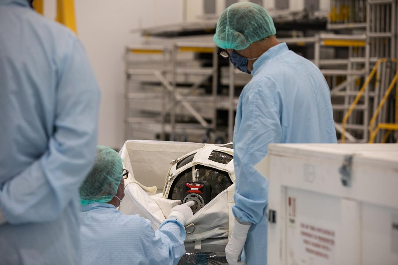
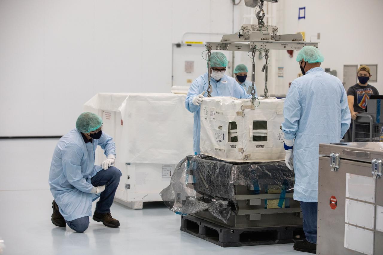
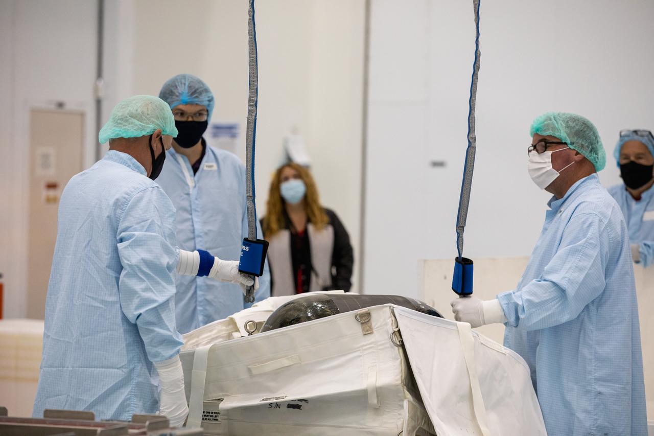
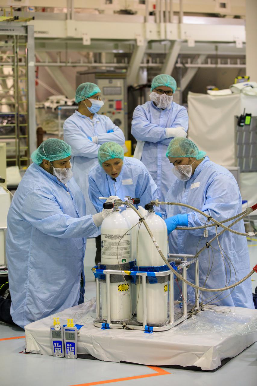
Technicians unpack and inspect a Nitrogen/Oxygen Recharge System (NORS) tank inside the Space Station Processing Facility high bay at NASA’s Kennedy Space Center in Florida on July 16, 2020. The NORS tanks and their support fixtures are designed to connect to the International Space Station’s existing air supply network to refill the previous generation of tanks installed during construction of the space station. These reusable tanks measure 3 feet long and 21 inches in diameter, and weigh about 200 pounds when filled. Once onboard, the tanks will be used to fill the oxygen and nitrogen tanks that supply the needed gases to the space station’s airlock for spacewalks. They could also be used to replenish the atmosphere inside the station. The NORS tanks will launch to the station later in the year on a commercial resupply mission.
Technicians unpack and inspect a Nitrogen/Oxygen Recharge System (NORS) tank inside the Space Station Processing Facility high bay at NASA’s Kennedy Space Center in Florida on July 16, 2020. The NORS tanks and their support fixtures are designed to connect to the International Space Station’s existing air supply network to refill the previous generation of tanks installed during construction of the space station. These reusable tanks measure 3 feet long and 21 inches in diameter, and weigh about 200 pounds when filled. Once onboard, the tanks will be used to fill the oxygen and nitrogen tanks that supply the needed gases to the space station’s airlock for spacewalks. They could also be used to replenish the atmosphere inside the station. The NORS tanks will launch to the station later in the year on a commercial resupply mission.

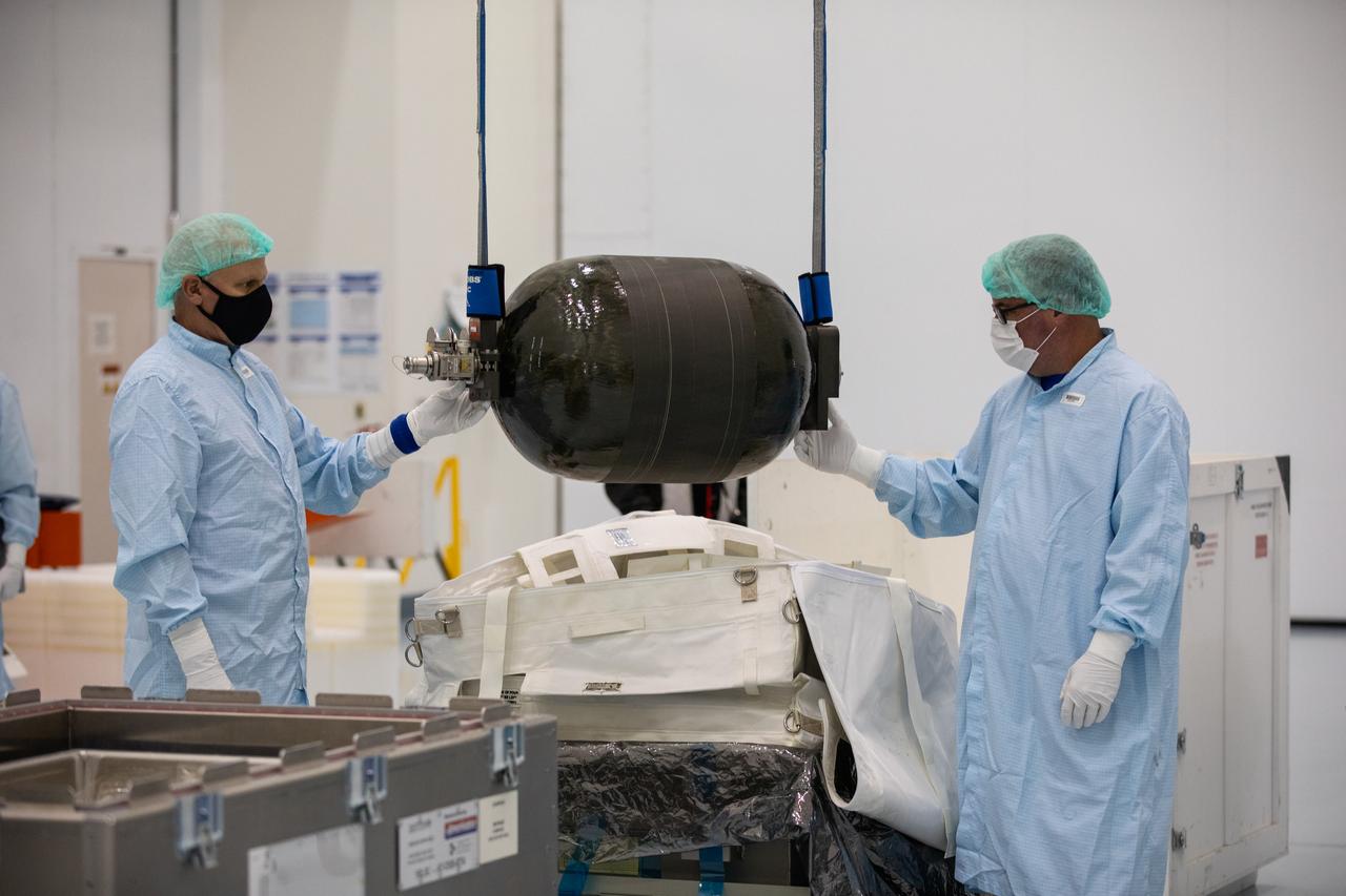
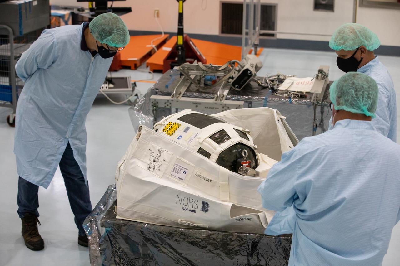
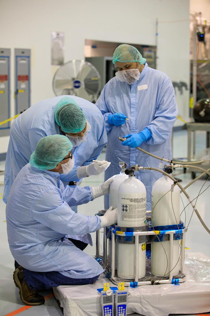
A technicians inspects a Nitrogen/Oxygen Recharge System (NORS) tank inside the Space Station Processing Facility high bay at NASA’s Kennedy Space Center in Florida on July 16, 2020. The NORS tanks and their support fixtures are designed to connect to the International Space Station’s existing air supply network to refill the previous generation of tanks installed during construction of the space station. These reusable tanks measure 3 feet long and 21 inches in diameter, and weigh about 200 pounds when filled. Once onboard, the tanks will be used to fill the oxygen and nitrogen tanks that supply the needed gases to the space station’s airlock for spacewalks. They could also be used to replenish the atmosphere inside the station. The NORS tanks will launch to the station later in the year on a commercial resupply mission.
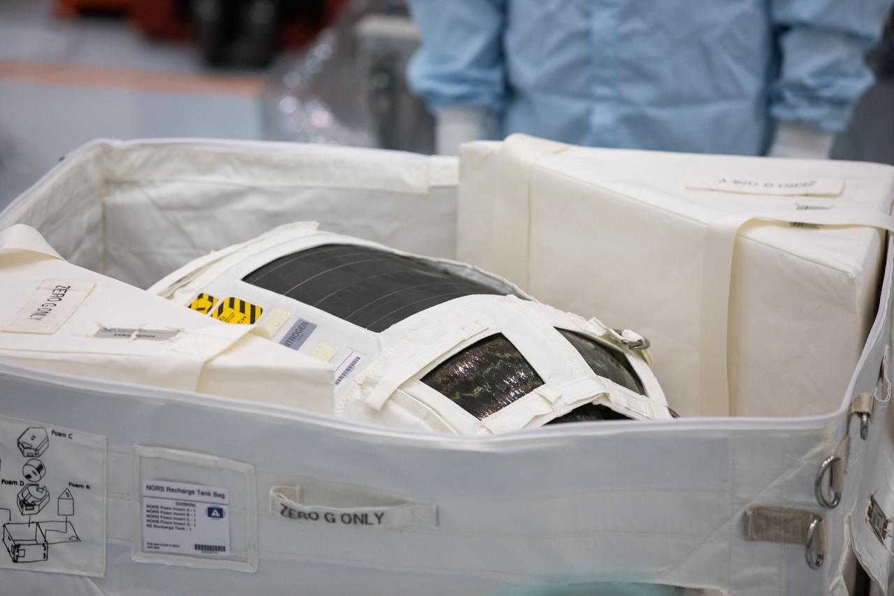
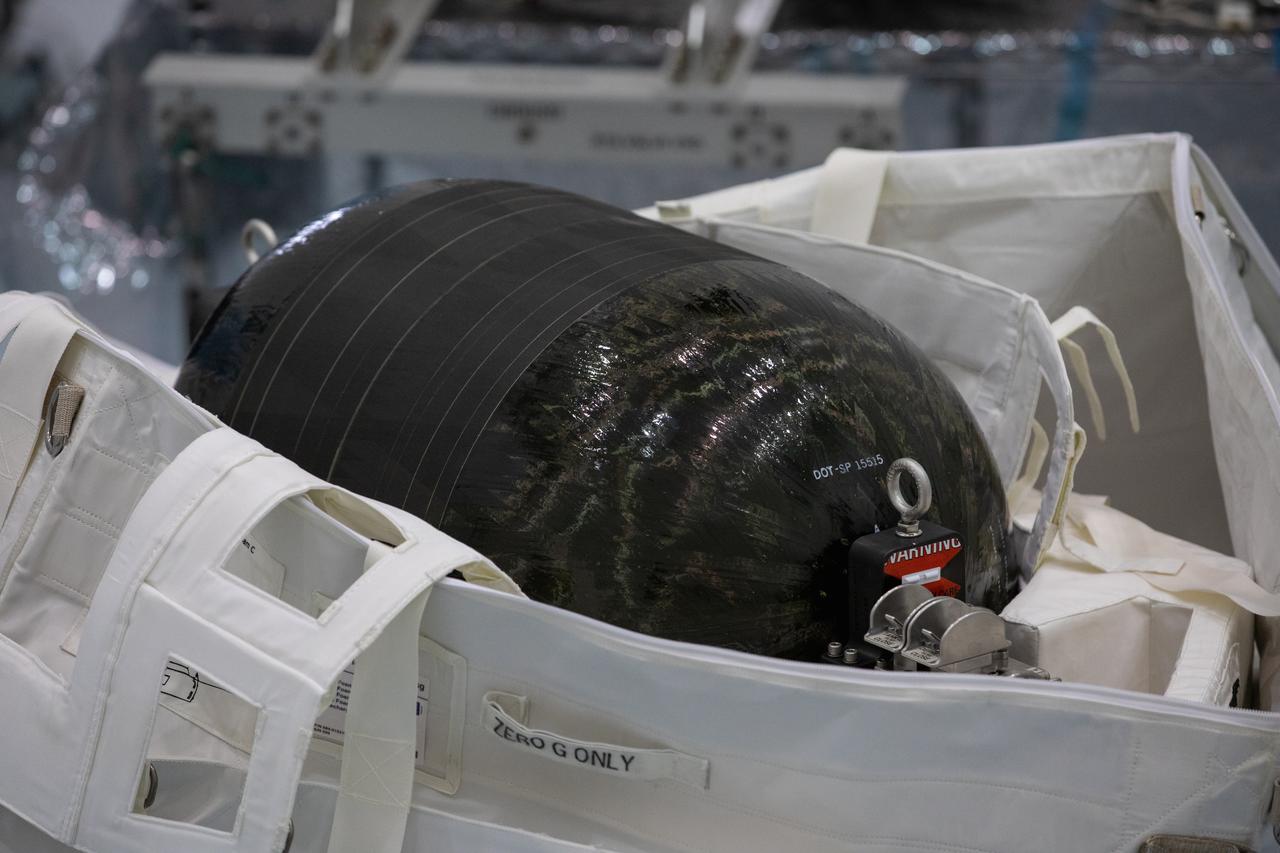
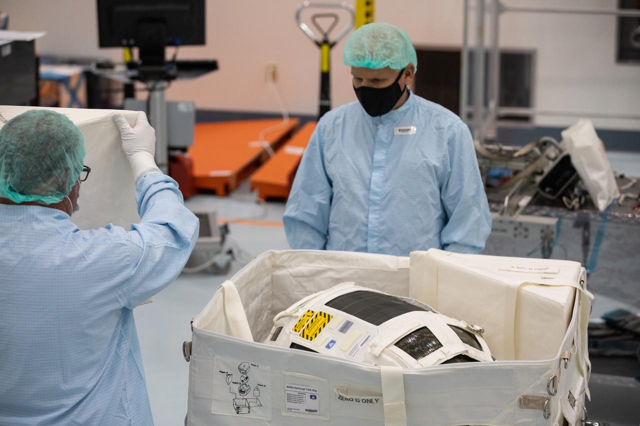
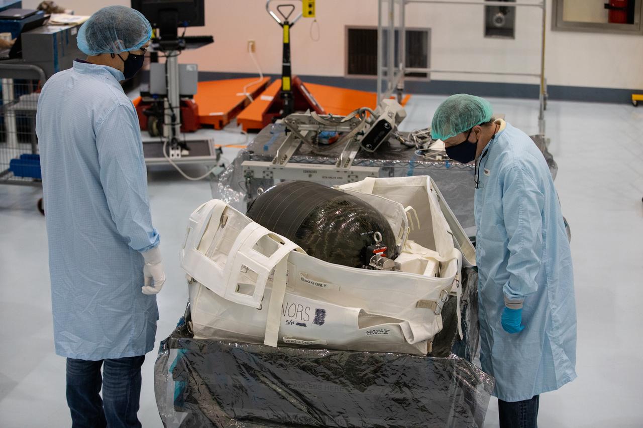
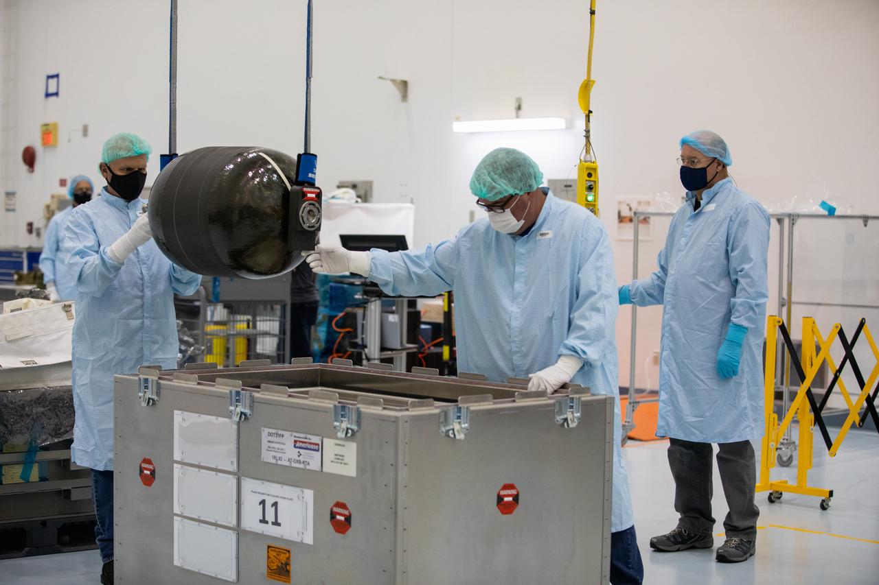
A Nitrogen/Oxygen Recharge System (NORS) tank is unpacked and readied for inspection inside the Space Station Processing Facility high bay at NASA’s Kennedy Space Center in Florida on July 16, 2020. The NORS tanks and their support fixtures are designed to connect to the International Space Station’s existing air supply network to refill the previous generation of tanks installed during construction of the space station. These reusable tanks measure 3 feet long and 21 inches in diameter, and weigh about 200 pounds when filled. Once onboard, the tanks will be used to fill the oxygen and nitrogen tanks that supply the needed gases to the space station’s airlock for spacewalks. They could also be used to replenish the atmosphere inside the station. The NORS tanks will launch to the station later in the year on a commercial resupply mission.
A Nitrogen/Oxygen Recharge System (NORS) tank is unpacked and readied for inspection inside the Space Station Processing Facility high bay at NASA’s Kennedy Space Center in Florida on July 16, 2020. The NORS tanks and their support fixtures are designed to connect to the International Space Station’s existing air supply network to refill the previous generation of tanks installed during construction of the space station. These reusable tanks measure 3 feet long and 21 inches in diameter, and weigh about 200 pounds when filled. Once onboard, the tanks will be used to fill the oxygen and nitrogen tanks that supply the needed gases to the space station’s airlock for spacewalks. They could also be used to replenish the atmosphere inside the station. The NORS tanks will launch to the station later in the year on a commercial resupply mission.
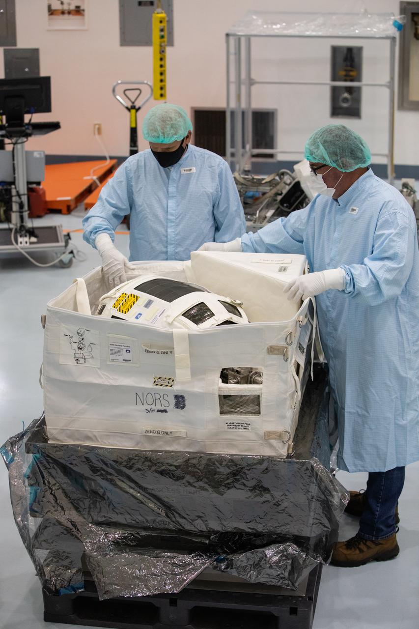
Technicians unpack and inspect a Nitrogen/Oxygen Recharge System (NORS) tank inside the Space Station Processing Facility high bay at NASA’s Kennedy Space Center in Florida on July 16, 2020. The NORS tanks and their support fixtures are designed to connect to the International Space Station’s existing air supply network to refill the previous generation of tanks installed during construction of the space station. These reusable tanks measure 3 feet long and 21 inches in diameter, and weigh about 200 pounds when filled. Once onboard, the tanks will be used to fill the oxygen and nitrogen tanks that supply the needed gases to the space station’s airlock for spacewalks. They could also be used to replenish the atmosphere inside the station. The NORS tanks will launch to the station later in the year on a commercial resupply mission.
Technicians unpack and inspect a Nitrogen/Oxygen Recharge System (NORS) tank inside the Space Station Processing Facility high bay at NASA’s Kennedy Space Center in Florida on July 16, 2020. The NORS tanks and their support fixtures are designed to connect to the International Space Station’s existing air supply network to refill the previous generation of tanks installed during construction of the space station. These reusable tanks measure 3 feet long and 21 inches in diameter, and weigh about 200 pounds when filled. Once onboard, the tanks will be used to fill the oxygen and nitrogen tanks that supply the needed gases to the space station’s airlock for spacewalks. They could also be used to replenish the atmosphere inside the station. The NORS tanks will launch to the station later in the year on a commercial resupply mission.

A Nitrogen/Oxygen Recharge System (NORS) tank is unpacked and readied for inspection inside the Space Station Processing Facility high bay at NASA’s Kennedy Space Center in Florida on July 16, 2020. The NORS tanks and their support fixtures are designed to connect to the International Space Station’s existing air supply network to refill the previous generation of tanks installed during construction of the space station. These reusable tanks measure 3 feet long and 21 inches in diameter, and weigh about 200 pounds when filled. Once onboard, the tanks will be used to fill the oxygen and nitrogen tanks that supply the needed gases to the space station’s airlock for spacewalks. They could also be used to replenish the atmosphere inside the station. The NORS tanks will launch to the station later in the year on a commercial resupply mission.
Technicians unpack and inspect a Nitrogen/Oxygen Recharge System (NORS) tank inside the Space Station Processing Facility high bay at NASA’s Kennedy Space Center in Florida on July 16, 2020. The NORS tanks and their support fixtures are designed to connect to the International Space Station’s existing air supply network to refill the previous generation of tanks installed during construction of the space station. These reusable tanks measure 3 feet long and 21 inches in diameter, and weigh about 200 pounds when filled. Once onboard, the tanks will be used to fill the oxygen and nitrogen tanks that supply the needed gases to the space station’s airlock for spacewalks. They could also be used to replenish the atmosphere inside the station. The NORS tanks will launch to the station later in the year on a commercial resupply mission.
Technicians unpack and inspect a Nitrogen/Oxygen Recharge System (NORS) tank inside the Space Station Processing Facility high bay at NASA’s Kennedy Space Center in Florida on July 16, 2020. The NORS tanks and their support fixtures are designed to connect to the International Space Station’s existing air supply network to refill the previous generation of tanks installed during construction of the space station. These reusable tanks measure 3 feet long and 21 inches in diameter, and weigh about 200 pounds when filled. Once onboard, the tanks will be used to fill the oxygen and nitrogen tanks that supply the needed gases to the space station’s airlock for spacewalks. They could also be used to replenish the atmosphere inside the station. The NORS tanks will launch to the station later in the year on a commercial resupply mission.
Technicians prepare to unpack and inspect a Nitrogen/Oxygen Recharge System (NORS) tank inside the Space Station Processing Facility high bay at NASA’s Kennedy Space Center in Florida on July 16, 2020. The NORS tanks and their support fixtures are designed to connect to the International Space Station’s existing air supply network to refill the previous generation of tanks installed during construction of the space station. These reusable tanks measure 3 feet long and 21 inches in diameter, and weigh about 200 pounds when filled. Once onboard, the tanks will be used to fill the oxygen and nitrogen tanks that supply the needed gases to the space station’s airlock for spacewalks. They could also be used to replenish the atmosphere inside the station. The NORS tanks will launch to the station later in the year on a commercial resupply mission.
Technicians unpack and inspect a Nitrogen/Oxygen Recharge System (NORS) tank inside the Space Station Processing Facility high bay at NASA’s Kennedy Space Center in Florida on July 16, 2020. The NORS tanks and their support fixtures are designed to connect to the International Space Station’s existing air supply network to refill the previous generation of tanks installed during construction of the space station. These reusable tanks measure 3 feet long and 21 inches in diameter, and weigh about 200 pounds when filled. Once onboard, the tanks will be used to fill the oxygen and nitrogen tanks that supply the needed gases to the space station’s airlock for spacewalks. They could also be used to replenish the atmosphere inside the station. The NORS tanks will launch to the station later in the year on a commercial resupply mission.
Technicians unpack and inspect a Nitrogen/Oxygen Recharge System (NORS) tank inside the Space Station Processing Facility high bay at NASA’s Kennedy Space Center in Florida on July 16, 2020. The NORS tanks and their support fixtures are designed to connect to the International Space Station’s existing air supply network to refill the previous generation of tanks installed during construction of the space station. These reusable tanks measure 3 feet long and 21 inches in diameter, and weigh about 200 pounds when filled. Once onboard, the tanks will be used to fill the oxygen and nitrogen tanks that supply the needed gases to the space station’s airlock for spacewalks. They could also be used to replenish the atmosphere inside the station. The NORS tanks will launch to the station later in the year on a commercial resupply mission.
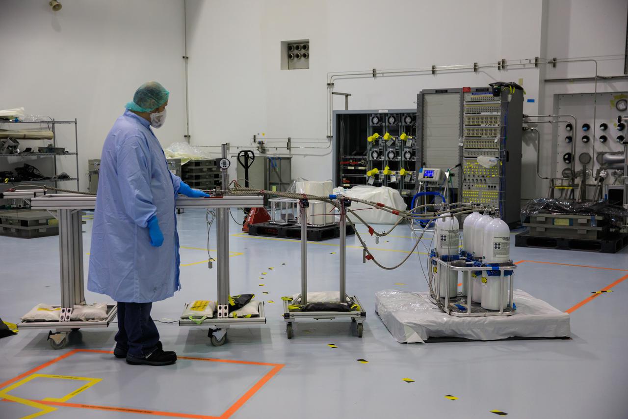
Inside the Space Station Processing Facility at NASA’s Kennedy Space Center in Florida on June 25, 2021, commercial off-the-shelf air tanks – normally used by divers – are filled with breathing air for use on the International Space Station. Using expendable air tanks for this purpose increases the efficiency of supplying air to the orbital laboratory. It also will supplement the reusable Nitrogen Oxygen Recharge System (NORS) tanks that NASA currently uses.
Inside the Space Station Processing Facility at NASA’s Kennedy Space Center in Florida on June 25, 2021, commercial off-the-shelf air tanks – normally used by divers – are filled with breathing air for use on the International Space Station. Using expendable air tanks for this purpose increases the efficiency of supplying air to the orbital laboratory. It also will supplement the reusable Nitrogen Oxygen Recharge System (NORS) tanks that NASA currently uses.
Inside the Space Station Processing Facility at NASA’s Kennedy Space Center in Florida on June 25, 2021, commercial off-the-shelf air tanks – normally used by divers – are filled with breathing air for use on the International Space Station. Using expendable air tanks for this purpose increases the efficiency of supplying air to the orbital laboratory. It also will supplement the reusable Nitrogen Oxygen Recharge System (NORS) tanks that NASA currently uses.
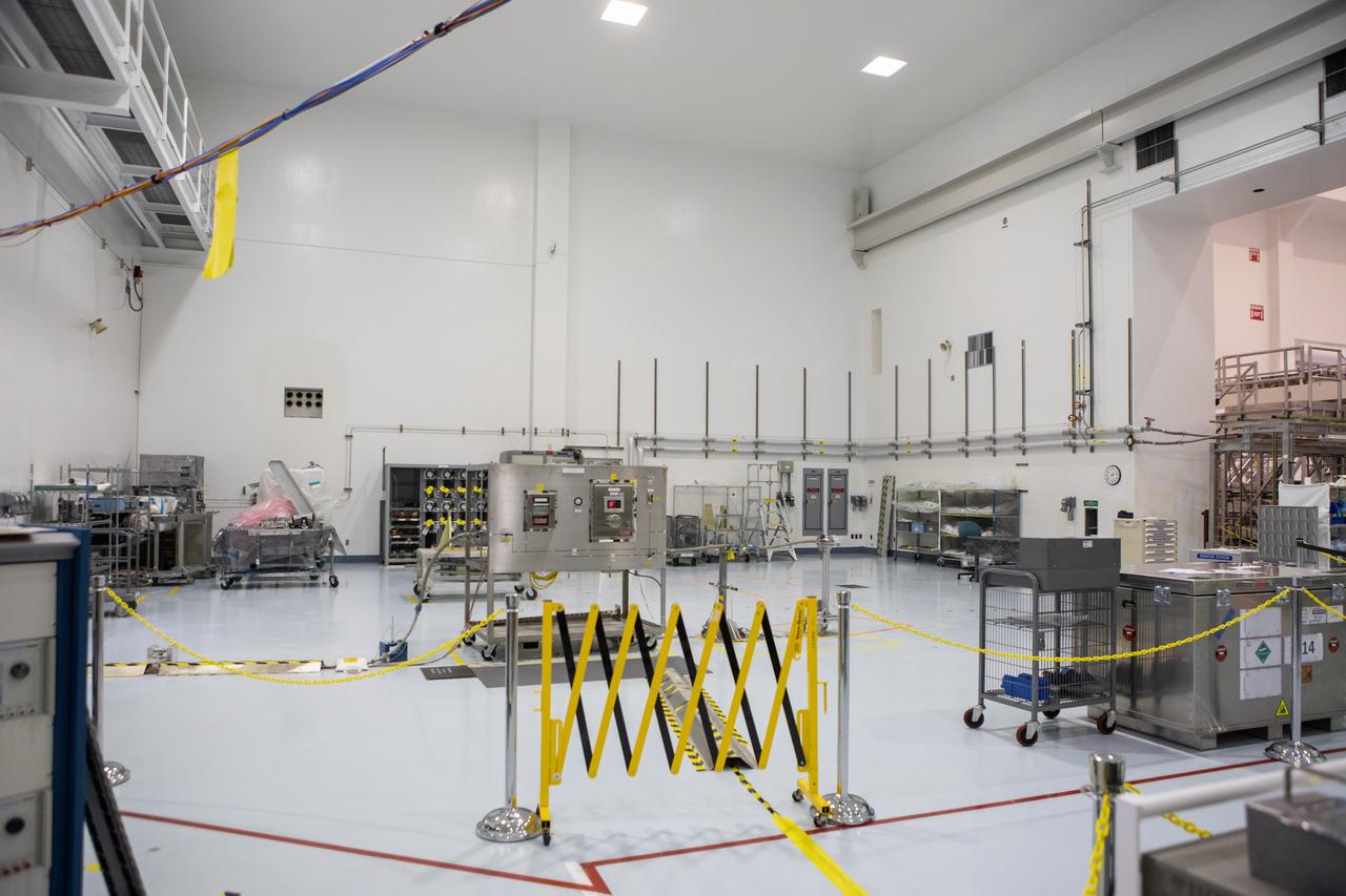
A Nitrogen Oxygen Recharge System (NORS) for the International Space Station is in view, center, in the high bay of the Space Station Processing Facility (SSPF) at NASA's Kennedy Space Center in Florida, on May 16, 2019. NORS are tanks that are used to fill the oxygen and nitrogen tanks that supply the needed gases to the station’s airlock for spacewalks and also are used as a secondary method to replenish the atmosphere inside the space station. The center is celebrating the SSPF’s 25th anniversary. The SSPF was built to process elements for the space station. Now it is providing support for current and future NASA and commercial provider programs, including Commercial Resupply Services, Artemis 1, sending the first woman and next man to the Moon, and deep space destinations including Mars.
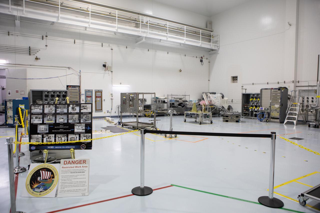
The processing area for the Nitrogen Oxygen Recharge System (NORS) for the International Space Station, is in view in the high bay of the Space Station Processing Facility (SSPF) at NASA's Kennedy Space Center in Florida, on May 16, 2019. NORS are tanks that are used to fill the oxygen and nitrogen tanks that supply the needed gases to the station’s airlock for spacewalks and also are used as a secondary method to replenish the atmosphere inside the space station. The center is celebrating the SSPF’s 25th anniversary. The SSPF was built to process elements for the space station. Now it is providing support for current and future NASA and commercial provider programs, including Commercial Resupply Services, Artemis 1, sending the first woman and next man to the Moon, and deep space destinations including Mars.
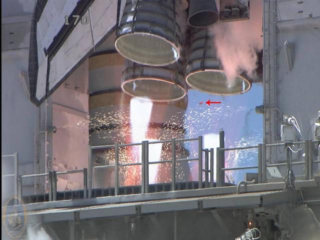
KENNEDY SPACE CENTER, FLA. - During liftoff of Space Shuttle Discovery on mission STS-121 on July 4, a camera captured a small piece of debris (pointed to by the arrow) that is believed to be a part of a shim used on the thermal protection system on the orbiter. The piece did not cause any damage nor will the loss be a concern for the mission or landing.

STS009-35-1622 (28 Nov-8 Dec 1983) --- In the Coral Sea to the last of Australia?s Great Barrier Reed, a massive area is covered with floating material. Its origin is presently unknown nor is it known to be of biological origin or man-made. However, it covers thousands of square miles, thus massive, and is unreported.
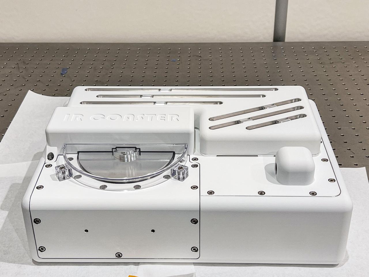
jsc2024e065155 (11/8/2023) --- Preflight view of the IR-COASTER experiment portion of the Euro Material Ageing investigation. The science objective of IR-COASTER is to study the evolution (stability, transformation or degradation) of samples containing organic molecules when exposed to space conditions, including the Solar UV flux when it is not filtered by the Earth's atmosphere nor simulated by lamps in the laboratory. Image courtesy of the Interuniversity Laboratory of Atmospheric Systems (LISA)..
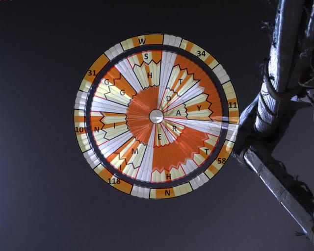
This annotated image was taken by a parachute-up-look camera aboard the protective back shell of NASA's Perseverance rover during its descent toward Mars' Jezero Crater on February 18, 2021. Using binary code, two messages have been encoded in the neutral white and international-orange parachute gores (the sections that make up the canopy's hemispherical shape). The inner portion spells out "DARE MIGHTY THINGS," with each word located on its own ring of gores. The outer band of the canopy provides GPS coordinates for NASA's Jet Propulsion Laboratory in Southern California, where the rover was built and the project is managed. Mars 2020 Perseverance Systems Engineer Ian Clark designed the binary code pattern. The saying is JPL's motto and is an abridgement of a quote from Teddy Roosevelt's "Strenuous Life" speech: "Far better is it to dare mighty things, to win glorious triumphs, even though checkered by failure ... than to rank with those poor spirits who neither enjoy nor suffer much, because they live in a gray twilight that knows not victory nor defeat." https://photojournal.jpl.nasa.gov/catalog/PIA24431

Two sizes of wind-sculpted ripples are evident in this view of the top surface of a Martian sand dune. Sand dunes and the smaller type of ripples also exist on Earth. The larger ripples -- roughly 10 feet (3 meters) apart -- are a type not seen on Earth nor previously recognized as a distinct type on Mars. The Mast Camera (Mastcam) on NASA's Curiosity Mars rover took the multiple component images of this scene on Dec. 13, 2015, during the 1,192nd Martian day, or sol, of the rover's work on Mars. That month, Curiosity was conducting the first close-up investigation ever made of active sand dunes anywhere other than Earth. The larger ripples have distinctive sinuous crest lines, compared to the smaller ripples. The location is part of "Namib Dune" in the Bagnold Dune Field, which forms a dark band along the northwestern flank of Mount Sharp. The component images were taken in early morning at this site, with the camera looking in the direction of the sun. This mosaic combining the images has been processed to brighten it and make the ripples more visible. The sand is very dark, both from the morning shadows and from the intrinsic darkness of the minerals that dominate its composition. http://photojournal.jpl.nasa.gov/catalog/PIA20755
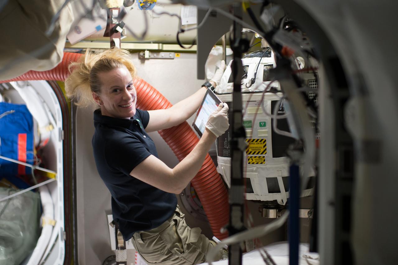
iss049e002733 (09/14/2016) --- Expedition 49 crew member and NASA astronaut Kate Rubins works with a Nitrogen/Oxygen Recharge System (NORS) tank aboard the International Space Station. The tanks are designed to be plugged into the station's existing air supply network to refill the crew’s breathable air supply. Each tank is pressurized up to 10,000 pounds per square inch to giving the station an atmosphere of nitrogen and oxygen like that of Earth, the system provides the pure oxygen astronauts breathe before beginning a spacewalk. The gases also are used in the station's ammonia-based cooling system and for other secondary uses.
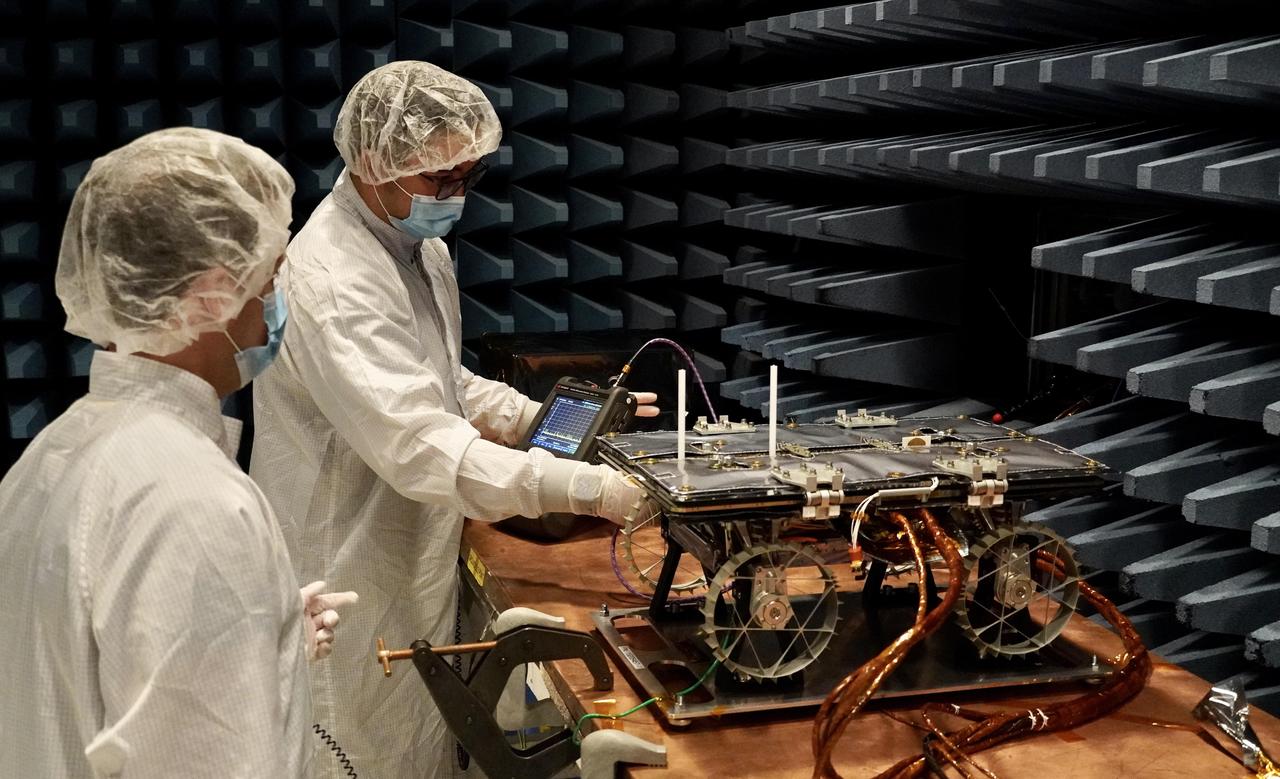
In a special chamber at NASA's Jet Propulsion Laboratory, engineers prepare to test a small rover that will go to the Moon as part of a NASA technology demonstration called CADRE (Cooperative Autonomous Distributed Robotic Exploration). The project is designed to show that a group of robotic spacecraft can work together as a team to accomplish tasks and record data autonomously – without explicit commands from mission controllers on Earth. This electromagnetic interference and compatibility testing took place in November 2023 in a chamber designed to absorb radio waves. Such testing is intended to confirm that the operation of the electronic subsystems do not interfere with each other nor with those on the lander, and that the rover can survive expected electromagnetic disturbances. Justin Schachter, left, and Manny Soriano are shown. https://photojournal.jpl.nasa.gov/catalog/PIA26166

Alfalfa (Medicago sativa) grown with nitrogen during preflight testing as part of Dissecting Beneficial Plant-Microbe Interactions and their Efficacy in the ISS Spaceflight Environment, a Model Study (Veg-06). This investigation examines spaceflight’s effects on the interactions between plants and nitrogen-fixing bacteria called rhizobia. These bacteria can take up nitrogen gas from the air and convert it into ammonia, a form of nitrogen plants can use for growth. One component of the nitrogen fixation emphasis in Veg-06 will compare the growth of alfalfa with rhizobia but no nitrogen fertilizer, alfalfa with rhizobia and a source of nitrogen fertilizer, and alfalfa with neither fertilizer nor rhizobia. Results could provide a fundamental understanding of the interactions of plants and microbes for nitrogen fixation in microgravity and advance the ways to grow plants for food on future space missions. Credit: Washington State University.
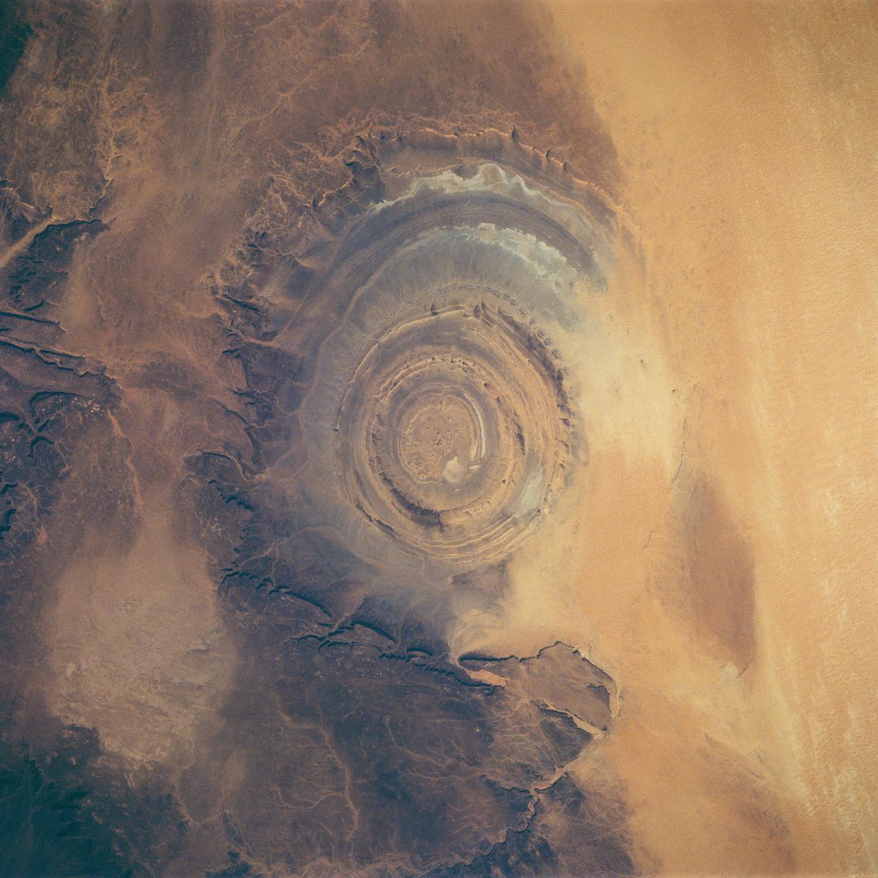
STS058-88-017 (18 Oct-1 Nov 1993) --- The eye-catching "bullseye" of the Richat Structure adds interest to the barren Gres de Chinguetti Plateau in central Mauretania, northwest Africa. It represents domally uplifted, layered (sedimentary) rocks that have been eroded by water and wind into the present shape. Desert sands have invaded the feature from the south. The origin of the structure is unknown. It is not an impact structure, because field work showed that strata are undisturbed and flat-lying in the middle of the feature, and no shock-altered rock could be found. There is no evidence for a salt dome or shale diapir, nor is there any geophysical evidence for an underlying dome of dense igneous rock having about the same density as the sedimentary layers.
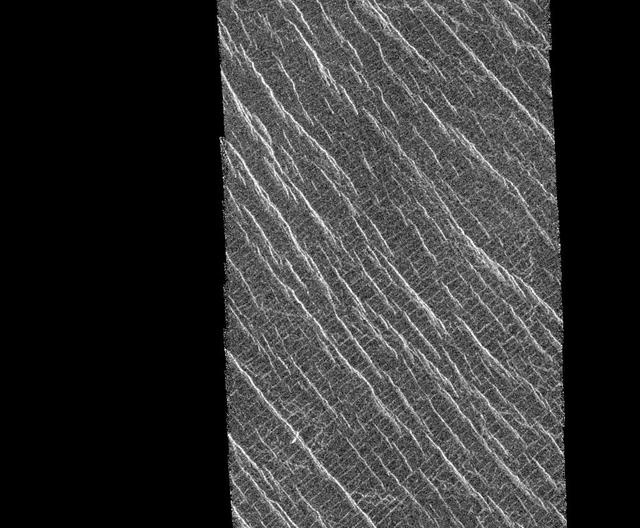
This mosaic shows an area of the Lakshmi region that is located 30 degrees north latitude and 333.3 degrees east longitude. (Longitude on Venus is measured from 0 degrees to 360 degrees east). The area shown measures about 37 kilometers (23 miles) wide and 80 kilometers (50 miles) long. Based on data from the Pioneer Venus Orbiter and the ground-based Arecibo Radar Observatory, it is known that this region is located on the low rise that separates Sedna Planitia and Guinevere Planitia, just to the west of Eistla Regio. Two sets of parallel lineations are seen intersecting almost at right angles. The fainter lineations are spaced at regular intervals of about one kilometer (0.6 mile) and extend beyond the boundary of the image. The width of the faint lineations is at the limit of resolution of the best Magellan images. The brighter, more dominant lineations are less regular and, in places, appear to begin and end where they intersect the fainter lineations. It is not clear whether the two sets of lineations are faults or fractures, but in other Magellan images, these bright lineations are associated with pit craters and volcanic features. This type of terrain has not been seen on Venus nor on other planets. North is at the top of the image. http://photojournal.jpl.nasa.gov/catalog/PIA00085
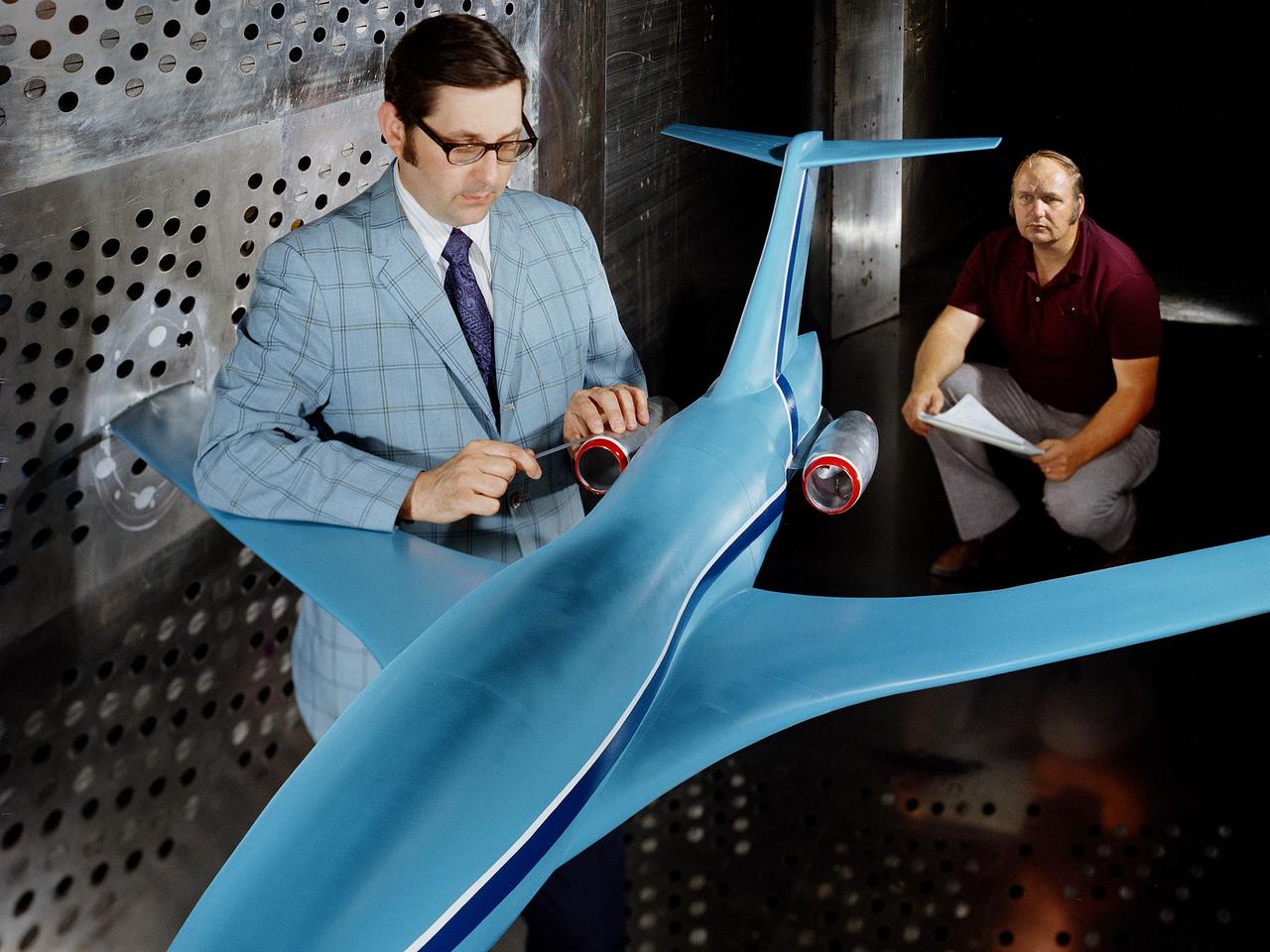
A researcher examines an Advanced Technology Transport model installed in the 8- by 6-Foot Supersonic Wind Tunnel at the National Aeronautics and Space Administration (NASA) Lewis Research Center. The Advanced Technology Transport concept was a 200-person supersonic transport aircraft that could cruise at Mach 0.9 to 0.98 with low noise and pollution outputs. General Electric and Pratt and Whitney responded to NASA Lewis’ call to design a propulsion system for the aircraft. The integration of the propulsion system with the airframe was one of the greatest challenges facing the designers of supersonic aircraft. The aircraft’s flow patterns and engine nacelles could significantly affect the performance of the engines. NASA Lewis researchers undertook a study of this 0.30-scale model of the Advanced Technology Transport in the 8- by 6-foot tunnel. The flow-through nacelles were located near the rear of the fuselage during the initial tests, seen here, and then moved under the wings for ensuing runs. Different engine cowl shapes were also analyzed. The researchers determined that nacelles mounted at the rear of the aircraft produced more efficient airflow patterns during cruising conditions at the desired velocities. The concept of the Advanced Technology Transport, nor any other US supersonic transport, has ever come to fruition. The energy crisis, environmental concerns, and inadequate turbofan technology of the 1970s were among the most significant reasons.
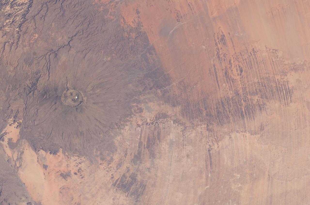
ISS030-E-005456 (26 Nov. 2011) --- Emi Koussi Volcano and Aorounga Impact Crater, Chad are featured in this image photographed by an Expedition 30 crew member on the International Space Station. This striking photograph features two examples of circular landscape features?labeled as craters?that were produced by very different geological processes. At left, the broad grey-green shield volcano of Emi Koussi is visible. The volcano is marked by three overlapping calderas formed by eruptions; these form a large oblong depression at the 3,415 meter ASL summit of the volcano. A smaller crater sits within the larger caldera depression. While volcanic activity has not been observed, nor is mentioned in the historical record, an active thermal area is located on the southern flank. The circular Aorounga Impact Crater is located approximately 110 kilometers to the southeast of Emi Koussi and has its origin in forces from above rather than eruptions from below. According to scientists, the Aorounga structure is thought to record a meteor impact approximately 345-370 million years ago. The circular feature visible at upper right may be only one of three impact craters formed by the same event ? the other two are buried by sand deposits. The linear features (lower right) that arc around Emi Koussi and overprint Aorounga and the surrounding bedrock are known as yardangs; these are rock ridges formed by wind erosion.

Despite being less famous than their elliptical and spiral galactic cousins, irregular dwarf galaxies, such as the one captured in this NASA/ESA Hubble Space Telescope image, are actually one of the most common types of galaxy in the Universe. Known as UGC 4459, this dwarf galaxy is located approximately 11 million light-years away in the constellation of Ursa Major (The Great Bear), a constellation that is also home to the Pinwheel Galaxy (M101), the Owl Nebula (M97), Messier 81, Messier 82 and several other galaxies all part of the M81 group. UGC 4459’s diffused and disorganised appearance is characteristic of an irregular dwarf galaxy. Lacking a distinctive structure or shape, irregular dwarf galaxies are often chaotic in appearance, with neither a nuclear bulge — a huge, tightly packed central group of stars — nor any trace of spiral arms — regions of stars extending from the centre of the galaxy. Astronomers suspect that some irregular dwarf galaxies were once spiral or elliptical galaxies, but were later deformed by the gravitational pull of nearby objects. Rich with young blue stars and older red stars, UGC 4459 has a stellar population of several billion. Though seemingly impressive, this is small when compared to the 200 to 400 billion stars in the Milky Way! Observations with Hubble have shown that because of their low masses, star formation is very low compared to larger galaxies. Only very little of their original gas has been turned into stars. Thus, these small galaxies are interesting to study to better understand primordial environments and the star formation process.

A massive phytoplankton bloom stained the waters of the Atlantic Ocean north of Iceland with brilliant jewel tones in late summer, 2014. The Moderate Resolution Imaging Spectroradiometer (MODIS) aboard NASA’s Aqua satellite captured this true-color image on August 2. Huge colonies of the floating, plant-like organisms create swirls of green, teal and turquoise and cover over 80% of the visible ocean off the northeast coast of Iceland. Marine phytoplankton require just the right amount of sunlight, dissolved nutrients and water temperatures which are not too hot, nor too cold to spark explosive reproduction and result in blooms which can cover hundreds of square kilometers. Phytoplankton form the base of the marine food chain, and are a rich food source for zooplankton, fish and other marine species. Some species, however, can deplete the water of oxygen and may become toxic to marine life. Credit: NASA/GSFC/Jeff Schmaltz/MODIS Land Rapid Response Team <b><a href="http://www.nasa.gov/audience/formedia/features/MP_Photo_Guidelines.html" rel="nofollow">NASA image use policy.</a></b> <b><a href="http://www.nasa.gov/centers/goddard/home/index.html" rel="nofollow">NASA Goddard Space Flight Center</a></b> enables NASA’s mission through four scientific endeavors: Earth Science, Heliophysics, Solar System Exploration, and Astrophysics. Goddard plays a leading role in NASA’s accomplishments by contributing compelling scientific knowledge to advance the Agency’s mission. <b>Follow us on <a href="http://twitter.com/NASAGoddardPix" rel="nofollow">Twitter</a></b> <b>Like us on <a href="http://www.facebook.com/pages/Greenbelt-MD/NASA-Goddard/395013845897?ref=tsd" rel="nofollow">Facebook</a></b> <b>Find us on <a href="http://instagram.com/nasagoddard?vm=grid" rel="nofollow">Instagram</a></b>
![Recent images of features in Saturn's C ring called "plateaus" have deepened the mystery surrounding them. It turns out that these bright bands have a streaky texture that is very different from the textures of the regions around them. The central feature in this image, called Plateau P5, is found approximately 52,700 miles (84,800 kilometers) from Saturn's center. It is situated amid some undulating structure that characterizes this region of the C ring. None of this structure is well understood. This image reveals that the plateau itself is shot through with elongated streaks. This provides information about ways in which the ring particles are interacting with each other, though scientists have not yet worked out what it all means. A more clumpy texture, similar to the "straw" seen previously in the A ring. Plateau regions are brighter than their surroundings, and have sharp edges. Recent evidence indicates that the plateaus do not actually contain more material than their surroundings, nor are they different in their chemical composition, which would mean that their greater brightness is likely due to smaller particle sizes. (If a given amount of mass is broken into smaller particles, it will spread out more [i.e., it will have more surface area].) These texture differences may give a clue about processes at the particle level that create the larger structures that Cassini has observed from greater distance throughout its mission at Saturn. These images were taken with the camera moving in sync with the orbits of individual ring particles. Therefore, any elongated structures are truly there in the rings, and are not an artifact of particles moving during the exposure (i.e., smear). This image was taken on the unilluminated side of the rings, with sunlight filtering through the rings as it would through a translucent bathroom window. Brighter regions in the image indicate more material scattering light toward the camera. This image was taken on May 29, 2017, with the Cassini spacecraft narrow-angle camera. The image was acquired on the sunlit side of the rings from a distance of about 39,800 miles (64,100 kilometers) away from the area pictured. The image scale is 1,460 feet (445 meters) per pixel. The phase angle, or sun-ring-spacecraft angle, is 137 degrees. https://photojournal.jpl.nasa.gov/catalog/PIA21619](https://images-assets.nasa.gov/image/PIA21619/PIA21619~small.jpg)
Recent images of features in Saturn's C ring called "plateaus" have deepened the mystery surrounding them. It turns out that these bright bands have a streaky texture that is very different from the textures of the regions around them. The central feature in this image, called Plateau P5, is found approximately 52,700 miles (84,800 kilometers) from Saturn's center. It is situated amid some undulating structure that characterizes this region of the C ring. None of this structure is well understood. This image reveals that the plateau itself is shot through with elongated streaks. This provides information about ways in which the ring particles are interacting with each other, though scientists have not yet worked out what it all means. A more clumpy texture, similar to the "straw" seen previously in the A ring. Plateau regions are brighter than their surroundings, and have sharp edges. Recent evidence indicates that the plateaus do not actually contain more material than their surroundings, nor are they different in their chemical composition, which would mean that their greater brightness is likely due to smaller particle sizes. (If a given amount of mass is broken into smaller particles, it will spread out more [i.e., it will have more surface area].) These texture differences may give a clue about processes at the particle level that create the larger structures that Cassini has observed from greater distance throughout its mission at Saturn. These images were taken with the camera moving in sync with the orbits of individual ring particles. Therefore, any elongated structures are truly there in the rings, and are not an artifact of particles moving during the exposure (i.e., smear). This image was taken on the unilluminated side of the rings, with sunlight filtering through the rings as it would through a translucent bathroom window. Brighter regions in the image indicate more material scattering light toward the camera. This image was taken on May 29, 2017, with the Cassini spacecraft narrow-angle camera. The image was acquired on the sunlit side of the rings from a distance of about 39,800 miles (64,100 kilometers) away from the area pictured. The image scale is 1,460 feet (445 meters) per pixel. The phase angle, or sun-ring-spacecraft angle, is 137 degrees. https://photojournal.jpl.nasa.gov/catalog/PIA21619
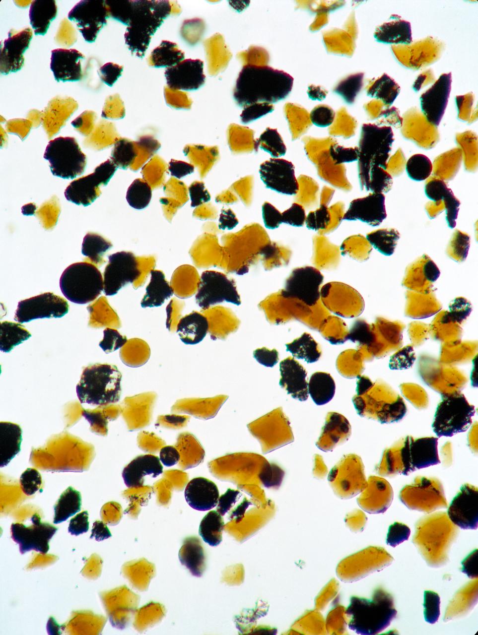
S73-15171 (4 Jan. 1973) --- These orange glass spheres and fragments are the finest particles ever brought back from the moon. Ranging in size from 20 to 45 microns (about 1/1000 of an inch) the particles are magnified 160 times in this photomicrograph made in the Lunar Receiving Laboratory at the Manned Spacecraft Center. The orange soil was brought back from the Taurus-Littrow landing site by the Apollo 17 crewmen. Scientist-astronaut Harrison H. "Jack" Schmitt discovered the orange soil at Shorty Crater during the second Apollo 17 extravehicular activity (EVA). This lunar material is being studied and analyzed by scientists in the LRL. The orange particles in this photomicrograph, which are intermixed with black and black-speckled grains, are about the same size as the particles that compose silt on Earth. Chemical analysis of the orange soil material has shown the sample to be similar to some of the samples brought back from the Apollo 11 (Sea of Tranquility) site several hundred miles to the southwest. Like those samples, it is rich in titanium (8%) and iron oxide (22%). But unlike the Apollo 11 samples, the orange soil is unexplainably rich in zinc ? an anomaly that has scientists in a quandary. This Apollo 17 sample is not high in volatile elements, nor do the minerals contain substantial amounts of water. These would have provided strong evidence of volcanic activity. On the other hand, the lack of agglutinates (rocks made up of a variety of minerals cemented together) indicates that the orange glass is probably not the product of meteorite impact -- strengthening the argument that the glass was produced by volcanic activity.
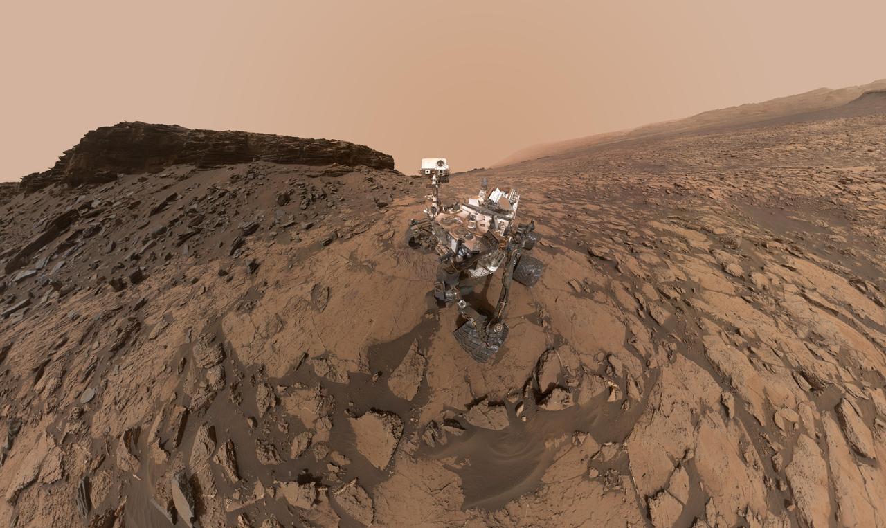
This self-portrait of NASA's Curiosity Mars rover shows the vehicle at the "Quela" drilling location in the "Murray Buttes" area on lower Mount Sharp. Key features on the skyline of this panorama are the dark mesa called "M12" to the left of the rover's mast and pale, upper Mount Sharp to the right of the mast. The top of M12 stands about 23 feet (7 meters) above the base of the sloping piles of rocks just behind Curiosity. The scene combines approximately 60 images taken by the Mars Hand Lens Imager (MAHLI) camera at the end of the rover's robotic arm. Most of the component images were taken on Sept. 17, 2016, during the 1,463rd Martian day, or sol, of Curiosity's work on Mars. Two component images of the drill-hole area in front of the rover were taken on Sol 1466 (Sept. 20) to show the hole created by collecting a drilled sample at Quela on Sol 1464 (Sept. 18). The skyline sweeps from west on the left to south-southwest on the right, with the rover's mast at northeast. The rover's location when it recorded this scene was where it ended a drive on Sol 1455, mapped at http://mars.nasa.gov/msl/multimedia/images/?ImageID=8029. The view does not include the rover's arm nor the MAHLI camera itself, except in the miniature scene reflected upside down in the parabolic mirror at the top of the mast. That mirror is part of Curiosity's Chemistry and Camera (ChemCam) instrument. MAHLI appears in the center of the mirror. Wrist motions and turret rotations on the arm allowed MAHLI to acquire the mosaic's component images. The arm was positioned out of the shot in the images, or portions of images, that were used in this mosaic. This process was used previously in acquiring and assembling Curiosity self-portraits taken at other sample-collection sites, including "Rocknest" (PIA16468), "Windjana" (PIA18390"), "Buckskin" (PIA19808) and "Gobabeb" (PIA20316). For scale, the rover's wheels are 20 inches (50 centimeters) in diameter and about 16 inches (40 centimeters) wide. http://photojournal.jpl.nasa.gov/catalog/PIA20844
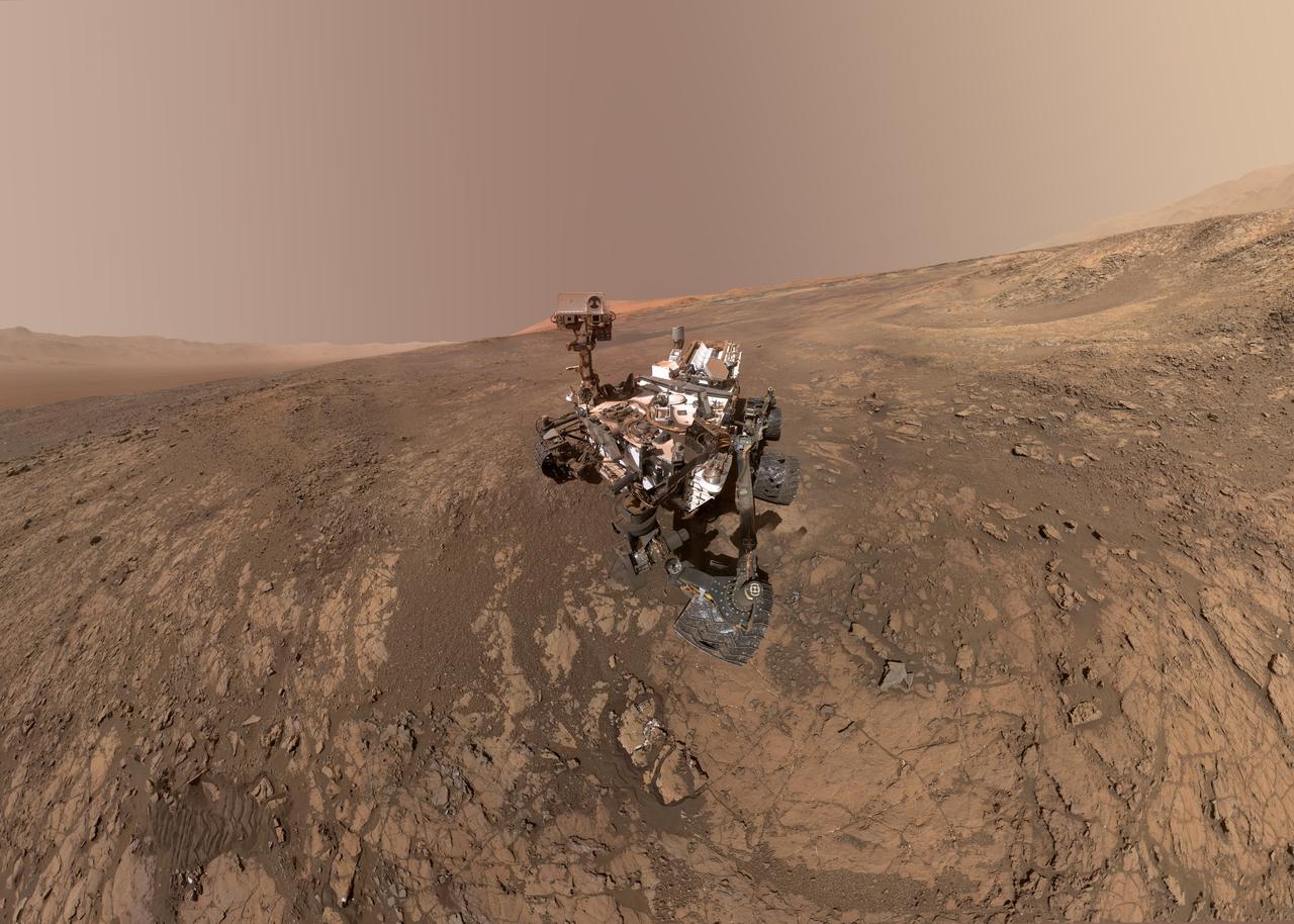
This self-portrait of NASA's Curiosity Mars rover shows the vehicle on Vera Rubin Ridge, which it's been investigating for the past several months. Directly behind the rover is the start of a clay-rich slope scientists are eager to begin exploring. In the coming week, Curiosity will begin to climb this slope. North is on the left and west is on the right, with Gale Crater's rim on the horizon of both edges. Poking up just behind Curiosity's mast is Mount Sharp, photobombing the robot's selfie. Curiosity landed on Mars five years ago with the intention of studying lower Mount Sharp, where it will remain for all of its time on Mars. The mountain's base provides access to layers formed over millions of years. These layers formed in the presence of water -- likely due to a lake or lakes that sat at the bottom of the mountain, which sits inside of Gale Crater. This mosaic was assembled from dozens of images taken by Curiosity's Mars Hands Lens Imager (MAHLI). They were all taken on Jan. 23, 2018, during Sol 1943. The view does not include the rover's arm nor the MAHLI camera itself, except in the miniature scene reflected upside down in the parabolic mirror at the top of the mast. That mirror is part of Curiosity's Chemistry and Camera (ChemCam) instrument. MAHLI appears in the center of the mirror. Wrist motions and turret rotations on the arm allowed MAHLI to acquire the mosaic's component images. The arm was positioned out of the shot in the images, or portions of images, that were used in this mosaic. A full-resolution image is available at https://photojournal.jpl.nasa.gov/catalog/PIA22207
![Recent images of features in Saturn's C ring called "plateaus" have deepened the mystery surrounding them. It turns out that these bright bands have a streaky texture that is very different from the textures of the regions around them. The central feature in this image, called Plateau P1, is found approximately 47,300 miles (76,200 kilometers) from Saturn's center. It is situated amid some undulating structure that characterizes this region of the C ring. None of this structure is well understood. This image reveals three different textures with different kinds of structure. The plateau itself is shot through with elongated streaks, while the brighter parts of the undulating structure have more clumpy texture that is similar to the "straw" seen previously in the A ring, and the dimmer parts of the undulating structure have no apparent texture at all. These textures provide information about different ways in which the ring particles are interacting with each other, though scientists have not yet worked out what it all means. Plateau regions are brighter than their surroundings, and have sharp edges. Recent evidence indicates that the plateaus do not actually contain more material than their surroundings, nor are they different in their chemical composition, which would mean that their greater brightness is likely due to smaller particle sizes. (If a given amount of mass is broken into smaller particles, it will spread out more [i.e., it will have more surface area].) These texture differences may give a clue about processes at the particle level that create the larger structures that Cassini has observed from greater distance throughout its mission at Saturn. These images were taken with the camera moving in sync with the orbits of individual ring particles. Therefore, any elongated structures are truly there in the rings, and are not an artifact of particles moving during the exposure (i.e., smear). This image was taken on June 4, 2017, with the Cassini spacecraft narrow-angle camera. The image was acquired on the sunlit side of the rings from a distance of (51,830 kilometers) away from the area pictured. The image scale is 1,070 feet (325 meters) per pixel. The phase angle, or sun-ring-spacecraft angle, is 80 degrees. https://photojournal.jpl.nasa.gov/catalog/PIA21618](https://images-assets.nasa.gov/image/PIA21618/PIA21618~small.jpg)
Recent images of features in Saturn's C ring called "plateaus" have deepened the mystery surrounding them. It turns out that these bright bands have a streaky texture that is very different from the textures of the regions around them. The central feature in this image, called Plateau P1, is found approximately 47,300 miles (76,200 kilometers) from Saturn's center. It is situated amid some undulating structure that characterizes this region of the C ring. None of this structure is well understood. This image reveals three different textures with different kinds of structure. The plateau itself is shot through with elongated streaks, while the brighter parts of the undulating structure have more clumpy texture that is similar to the "straw" seen previously in the A ring, and the dimmer parts of the undulating structure have no apparent texture at all. These textures provide information about different ways in which the ring particles are interacting with each other, though scientists have not yet worked out what it all means. Plateau regions are brighter than their surroundings, and have sharp edges. Recent evidence indicates that the plateaus do not actually contain more material than their surroundings, nor are they different in their chemical composition, which would mean that their greater brightness is likely due to smaller particle sizes. (If a given amount of mass is broken into smaller particles, it will spread out more [i.e., it will have more surface area].) These texture differences may give a clue about processes at the particle level that create the larger structures that Cassini has observed from greater distance throughout its mission at Saturn. These images were taken with the camera moving in sync with the orbits of individual ring particles. Therefore, any elongated structures are truly there in the rings, and are not an artifact of particles moving during the exposure (i.e., smear). This image was taken on June 4, 2017, with the Cassini spacecraft narrow-angle camera. The image was acquired on the sunlit side of the rings from a distance of (51,830 kilometers) away from the area pictured. The image scale is 1,070 feet (325 meters) per pixel. The phase angle, or sun-ring-spacecraft angle, is 80 degrees. https://photojournal.jpl.nasa.gov/catalog/PIA21618

In this rare image taken on July 19, 2013, the wide-angle camera on NASA's Cassini spacecraft has captured Saturn's rings and our planet Earth and its moon in the same frame. It is only one footprint in a mosaic of 33 footprints covering the entire Saturn ring system (including Saturn itself). At each footprint, images were taken in different spectral filters for a total of 323 images: some were taken for scientific purposes and some to produce a natural color mosaic. This is the only wide-angle footprint that has the Earth-moon system in it. The dark side of Saturn, its bright limb, the main rings, the F ring, and the G and E rings are clearly seen; the limb of Saturn and the F ring are overexposed. The "breaks" in the brightness of Saturn's limb are due to the shadows of the rings on the globe of Saturn, preventing sunlight from shining through the atmosphere in those regions. The E and G rings have been brightened for better visibility. Earth, which is 898 million miles (1.44 billion kilometers) away in this image, appears as a blue dot at center right; the moon can be seen as a fainter protrusion off its right side. An arrow indicates their location in the annotated version. (The two are clearly seen as separate objects in the accompanying composite image PIA14949.) The other bright dots nearby are stars. This is only the third time ever that Earth has been imaged from the outer solar system. The acquisition of this image, along with the accompanying composite narrow- and wide-angle image of Earth and the moon and the full mosaic from which both are taken, marked the first time that inhabitants of Earth knew in advance that their planet was being imaged. That opportunity allowed people around the world to join together in social events to celebrate the occasion. This view looks toward the unilluminated side of the rings from about 20 degrees below the ring plane. Images taken using red, green and blue spectral filters were combined to create this natural color view. The images were obtained with the Cassini spacecraft wide-angle camera on July 19, 2013 at a distance of approximately 753,000 miles (1.212 million kilometers) from Saturn, and approximately 898.414 million miles (1.445858 billion kilometers) from Earth. Image scale on Saturn is 43 miles (69 kilometers) per pixel; image scale on the Earth is 53,820 miles (86,620 kilometers) per pixel. The illuminated areas of neither Earth nor the Moon are resolved here. Consequently, the size of each "dot" is the same size that a point of light of comparable brightness would have in the wide-angle camera. http://photojournal.jpl.nasa.gov/catalog/PIA17171
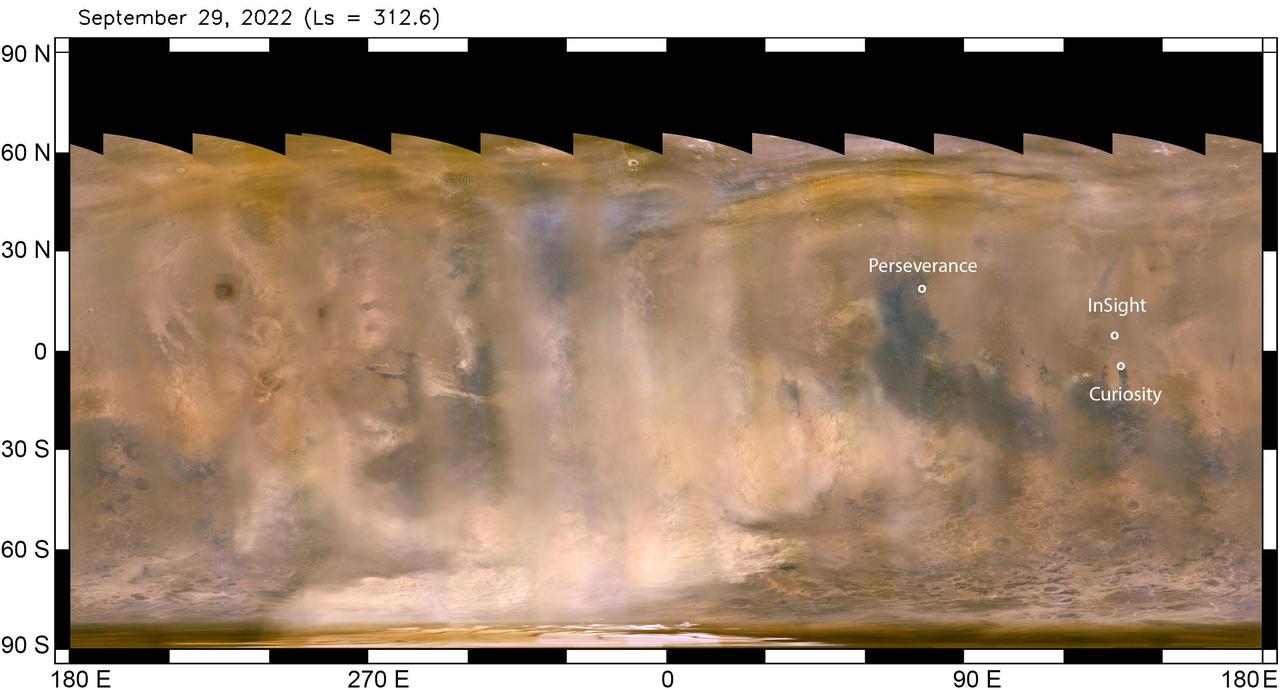
The beige clouds seen in this flat global map of Mars are a continent-size dust storm captured on Sept. 29, 2022 by the Mars Color Imager (MARCI) camera aboard NASA's Mars Reconnaissance Orbiter (MRO). As MRO passes over the planet, MARCI takes linear images – essentially strips – of the planet's circumference each day. The images are then stitched together to create a daily global map of the planet, showing atmospheric features across the planet as seen at the same time of day (mid-afternoon). Comparison of daily maps show atmospheric changes over time. Besides providing unique scientific data, MARCI's global maps are useful for monitoring weather changes that could affect NASA's surface missions. The agency's Perseverance, Curiosity, and InSight missions are also labeled, showing the vast distances between them. NASA's Perseverance rover and Ingenuity helicopter, are located at the white dot farthest north, roughly 2,147 miles (3,455 kilometers) from the agency's InSight lander, just above the equator. The Curiosity rover is just below the equator, about 373 miles (600 kilometers) from InSight. Neither Curiosity nor Perseverance and Ingenuity (the helicopter must remain relatively close to Perseverance, which serves as its base station) can travel the distance to the solar-powered InSight lander. The regional dust storm in this map was first observed Sept. 21. By the time these images were taken (Sept. 29), it had expanded considerably. Within the following week, the storm appeared to have entered its decay phase, when it's no longer lifting dust into the atmosphere. At that point, the dust that has already been lofted into the atmosphere and spread far beyond the dust-raising sector can take weeks to settle back to the surface. While this particular storm was roughly 2,175 miles (3,500 kilometers) from InSight, it lofted enough dust to significantly reduce the energy being produced by the lander's solar arrays, which have become covered by dust since the spacecraft landed in November 2018. The lander has long since surpassed its primary mission. With its power steadily declining, it is now close to the end of its extended mission, conducting "bonus science" by measuring marsquakes, which reveal details about the deep interior of the Red Planet. https://photojournal.jpl.nasa.gov/catalog/PIA25412
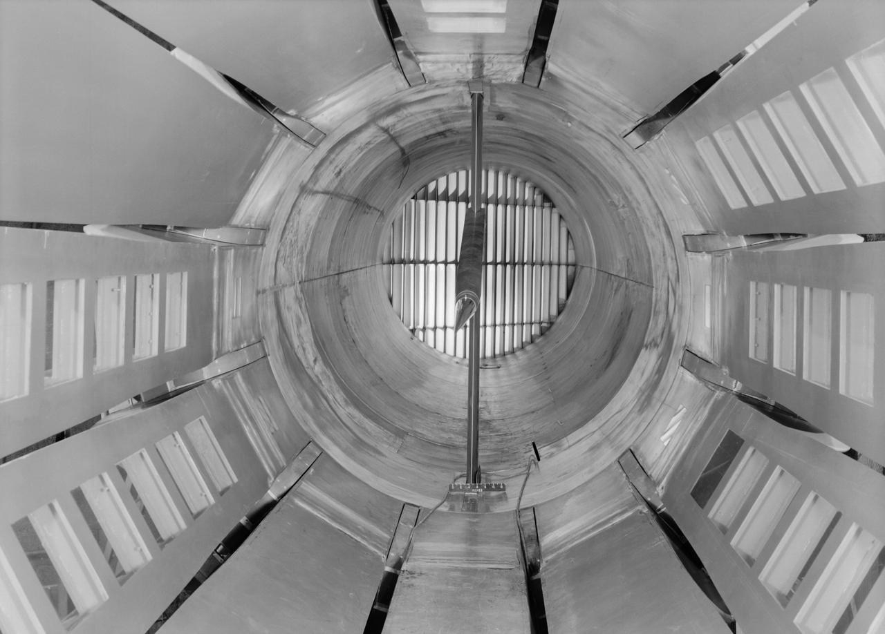
Interior view of the slotted throat test section installed in the 8-Foot High Speed Tunnel (HST) in 1950. The slotted region is about 160 inches in length. In this photograph, the sting-type model support is seen straight on. In a NASA report, the test section is described as follows: The test section of the Langley 8-foot transonic tunnel is dodecagonal in cross section and has a cross-sectional area of about 43 square feet. Longitudinal slots are located between each of the 12 wall panels to allow continuous operation through the transonic speed range. The slots contain about 11 percent of the total periphery of the test section. Six of the twelve panels have windows in them to allow for schlieren observations. The entire test section is enclosed in a hemispherical shaped chamber. John Becker noted that the tunnel s final achievement was the development and use in routine operations of the first transonic slotted throat. The investigations of wing-body shapes in this tunnel led to Whitcomb s discovery of the transonic area rule. James Hansen described the origins of the the slotted throat as follows: In 1946 Langley physicist Ray H. Wright conceived a way to do transonic research effectively in a wind tunnel by placing slots in the throat of the test section. The concept for what became known as the slotted-throat or slotted-wall tunnel came to Wright not as a solution to the chronic transonic problem, but as a way to get rid of wall interference (i.e., the mutual effect of two or more meeting waves or vibrations of any kind caused by solid boundaries) at subsonic speeds. For most of the year before Wright came up with this idea, he had been trying to develop a theoretical understanding of wall interference in the 8-Foot HST, which was then being repowered for Mach 1 capability. When Wright presented these ideas to John Stack, the response was enthusiastic but neither Wright nor Stack thought of slotted-throats as a solution to the transonic problem, only the wall interference problem. It was an accidental discovery which showed that slotted throats might solve the transonic problem. Most engineers were skeptical but Stack persisted. Initially, plans were to modify the 16-Foot tunnel but in the spring of 1948, Stack announced that the 8-Foot HST would also be modified. As Hansen notes: The 8-Foot HST began regular transonic operations for research purposes on 6 October 1950. The concept was a success and led to plans for a new wind tunnel which would be known as the 8-Foot Transonic Pressure Tunnel. -- Published in U.S., National Advisory Committee for Aeronautics, Characteristics of Nine Research Wind Tunnels of the Langley Aeronautical Laboratory, 1957, pp. 17, 22 James R. Hansen, Engineer in Charge, NASA SP-4305, p. 454 and Chapter 11, The Slotted Tunnel and the Area Rule.

This stunning image, captured by the NASA/ESA Hubble Space Telescope’s Advanced Camera for Surveys (ACS), shows part of the sky in the constellation of Sagittarius (The Archer). The region is rendered in exquisite detail — deep red and bright blue stars are scattered across the frame, set against a background of thousands of more distant stars and galaxies. Two features are particularly striking: the colors of the stars, and the dramatic crosses that burst from the centers of the brightest bodies. While some of the colors in this frame have been enhanced and tweaked during the process of creating the image from the observational data, different stars do indeed glow in different colors. Stars differ in color according to their surface temperature: very hot stars are blue or white, while cooler stars are redder. They may be cooler because they are smaller, or because they are very old and have entered the red giant phase, when an old star expands and cools dramatically as its core collapses. The crosses are nothing to do with the stars themselves, and, because Hubble orbits above Earth’s atmosphere, nor are they due to any kind of atmospheric disturbance. They are actually known as diffraction spikes, and are caused by the structure of the telescope itself. Like all big modern telescopes, Hubble uses mirrors to capture light and form images. Its secondary mirror is supported by struts, called telescope spiders, arranged in a cross formation, and they diffract the incoming light. Diffraction is the slight bending of light as it passes near the edge of an object. Every cross in this image is due to a single set of struts within Hubble itself! Whilst the spikes are technically an inaccuracy, many astrophotographers choose to emphasize and celebrate them as a beautiful feature of their images. Image credit: ESA/Hubble & NASA <b><a href="http://www.nasa.gov/audience/formedia/features/MP_Photo_Guidelines.html" rel="nofollow">NASA image use policy.</a></b> <b><a href="http://www.nasa.gov/centers/goddard/home/index.html" rel="nofollow">NASA Goddard Space Flight Center</a></b> enables NASA’s mission through four scientific endeavors: Earth Science, Heliophysics, Solar System Exploration, and Astrophysics. Goddard plays a leading role in NASA’s accomplishments by contributing compelling scientific knowledge to advance the Agency’s mission. <b>Follow us on <a href="http://twitter.com/NASAGoddardPix" rel="nofollow">Twitter</a></b> <b>Like us on <a href="http://www.facebook.com/pages/Greenbelt-MD/NASA-Goddard/395013845897?ref=tsd" rel="nofollow">Facebook</a></b> <b>Find us on <a href="http://instagrid.me/nasagoddard/?vm=grid" rel="nofollow">Instagram</a></b>
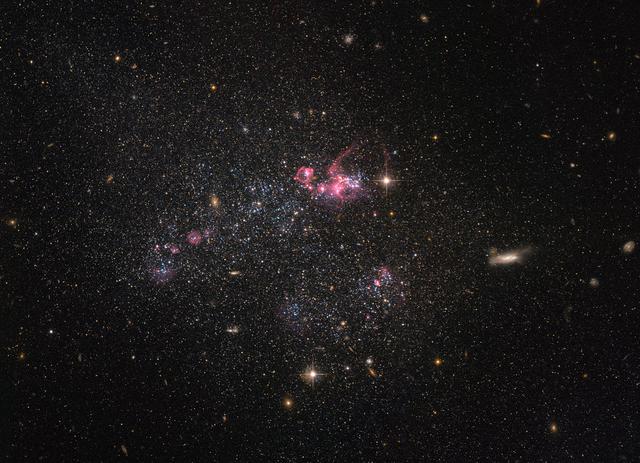
Despite being less famous than their elliptical and spiral galactic cousins, irregular dwarf galaxies, such as the one captured in this NASA/ESA Hubble Space Telescope image, are actually one of the most common types of galaxy in the universe. Known as UGC 4459, this dwarf galaxy is located approximately 11 million light-years away in the constellation of Ursa Major (The Great Bear), a constellation that is also home to the Pinwheel Galaxy (M101), the Owl Nebula (M97), Messier 81, Messier 82 and several other galaxies all part of the M81 group. UGC 4459’s diffused and disorganized appearance is characteristic of an irregular dwarf galaxy. Lacking a distinctive structure or shape, irregular dwarf galaxies are often chaotic in appearance, with neither a nuclear bulge — a huge, tightly packed central group of stars — nor any trace of spiral arms — regions of stars extending from the center of the galaxy. Astronomers suspect that some irregular dwarf galaxies were once spiral or elliptical galaxies, but were later deformed by the gravitational pull of nearby objects. Rich with young blue stars and older red stars, UGC 4459 has a stellar population of several billion. Though seemingly impressive, this is small when compared to the 200 to 400 billion stars in the Milky Way! Observations with Hubble have shown that because of their low masses of dwarf galaxies like UGC 4459, star formation is very low compared to larger galaxies. Only very little of their original gas has been turned into stars. Thus, these small galaxies are interesting to study to better understand primordial environments and the star formation process. Image Credit: ESA/Hubble and NASA; Acknowledgement: Judy Schmidt <b><a href="http://www.nasa.gov/audience/formedia/features/MP_Photo_Guidelines.html" rel="nofollow">NASA image use policy.</a></b> <b><a href="http://www.nasa.gov/centers/goddard/home/index.html" rel="nofollow">NASA Goddard Space Flight Center</a></b> enables NASA’s mission through four scientific endeavors: Earth Science, Heliophysics, Solar System Exploration, and Astrophysics. Goddard plays a leading role in NASA’s accomplishments by contributing compelling scientific knowledge to advance the Agency’s mission. <b>Follow us on <a href="http://twitter.com/NASAGoddardPix" rel="nofollow">Twitter</a></b> <b>Like us on <a href="http://www.facebook.com/pages/Greenbelt-MD/NASA-Goddard/395013845897?ref=tsd" rel="nofollow">Facebook</a></b> <b>Find us on <a href="http://instagrid.me/nasagoddard/?vm=grid" rel="nofollow">Instagram</a></b>