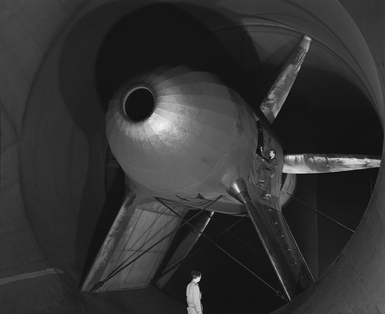
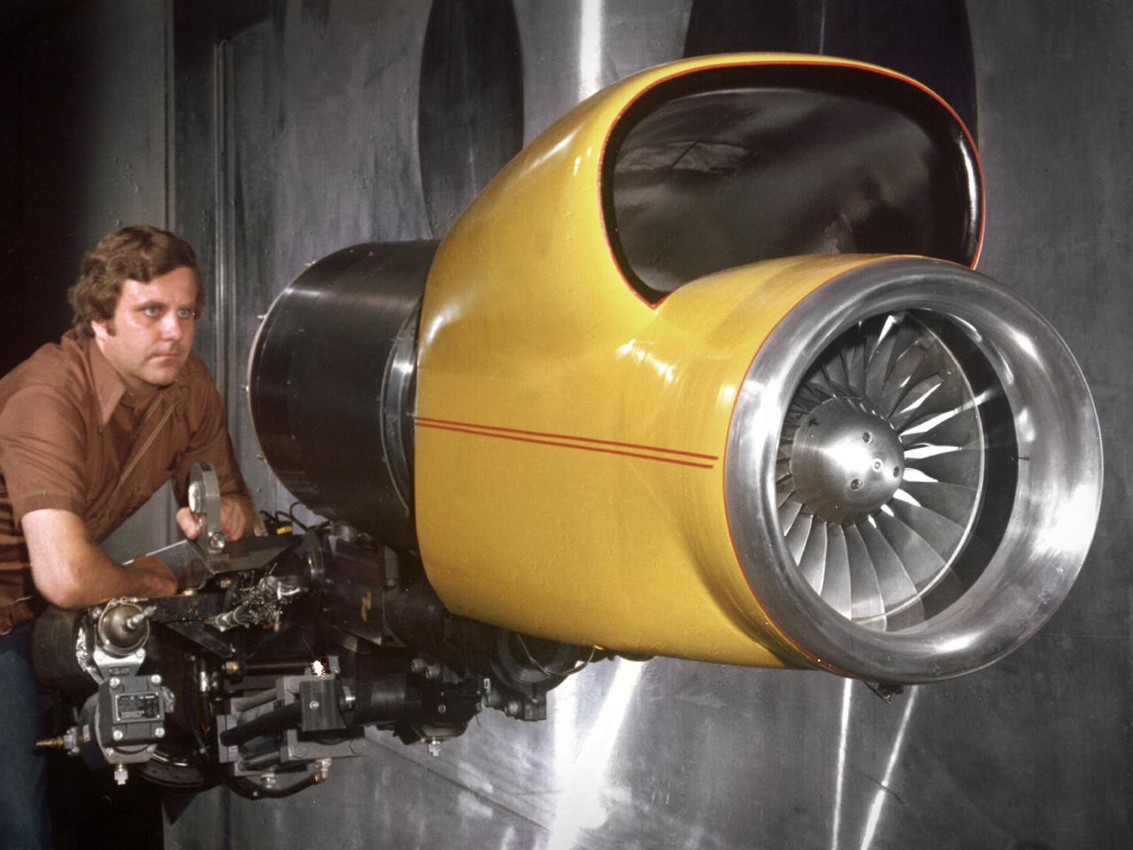
Publicity Shot of close up of Nacell, Drive Nacel and cooling vent in nose for wind tunnel in NACA Ames 40x80 foot Wind Tunnel.
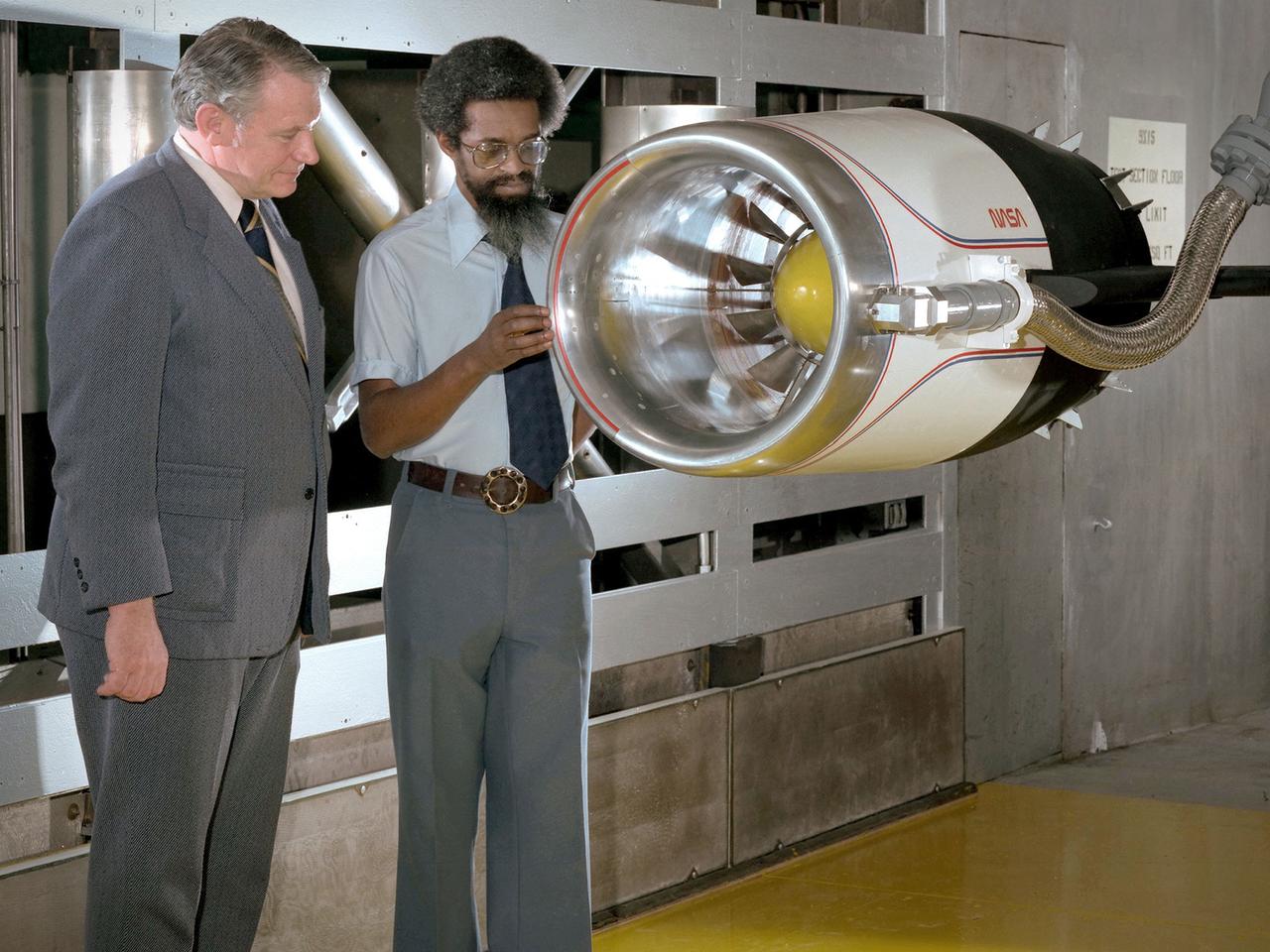
Center Director John McCarthy, left, and researcher Al Johns pose with a one-third scale model of a Grumman Aerospace tilt engine nacelle for Vertical and Short Takeoff and Landing (V/STOL) in the 9- by 15-Foot Low Speed Wind Tunnel at the National Aeronautics and Space Administration (NASA) Lewis Research Center. Lewis researchers had been studying tilt nacelle and inlet issues for several years. One area of concern was the inlet flow separation during the transition from horizontal to vertical flight. The separation of air flow from the inlet’s internal components could significantly stress the fan blades or cause a loss of thrust. In 1978 NASA researchers Robert Williams and Al Johns teamed with Grumman’s H.C. Potonides to develop a series of tests in the Lewis 9- by 15-foot tunnel to study a device designed to delay the flow separation by blowing additional air into the inlet. A jet of air, supplied through the hose on the right, was blown over the inlet surfaces. The researchers verified that the air jet slowed the flow separation. They found that the blowing on boundary layer control resulted in a doubling of the angle-of-attack and decreases in compressor blade stresses and fan distortion. The tests were the first time the concept of blowing air for boundary layer control was demonstrated. Boundary layer control devices like this could result in smaller and lighter V/STOL inlets.
C-5 Re-engineering and Realiability Program semi-span model; 11ft w.t. Test-11-0103; Throught flow nacelle and inboard nacelle with turbine propulsion systems unit with Doug Atler
C-5 Re-engineering and Realiability Program semi-span model; 11ft w.t. Test-11-0103; Throught flow nacelle and inboard nacelle with turbine propulsion systems unit
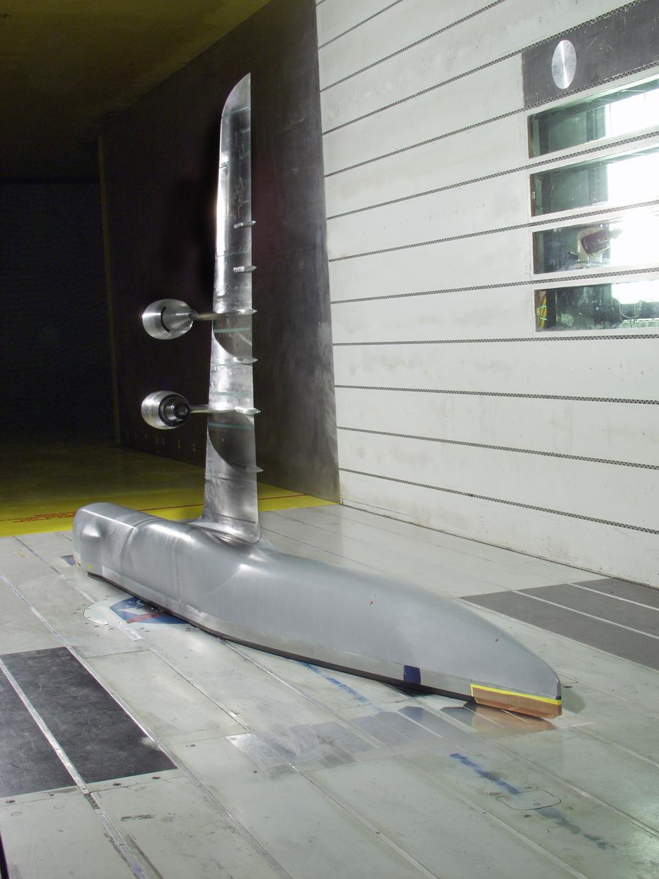
C-5 Re-engineering and Realiability Program semi-span model; 11ft w.t. Test-11-0103; Throught flow nacelle and inboard nacelle with turbine propulsion systems unit
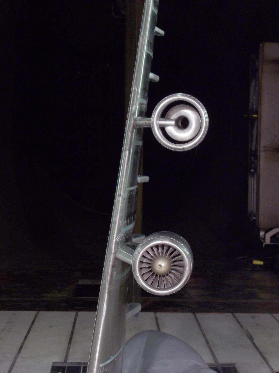
C-5 Re-engineering and Realiability Program semi-span model; 11ft w.t. Test-11-0103; Throught flow nacelle and inboard nacelle with turbine propulsion systems unit
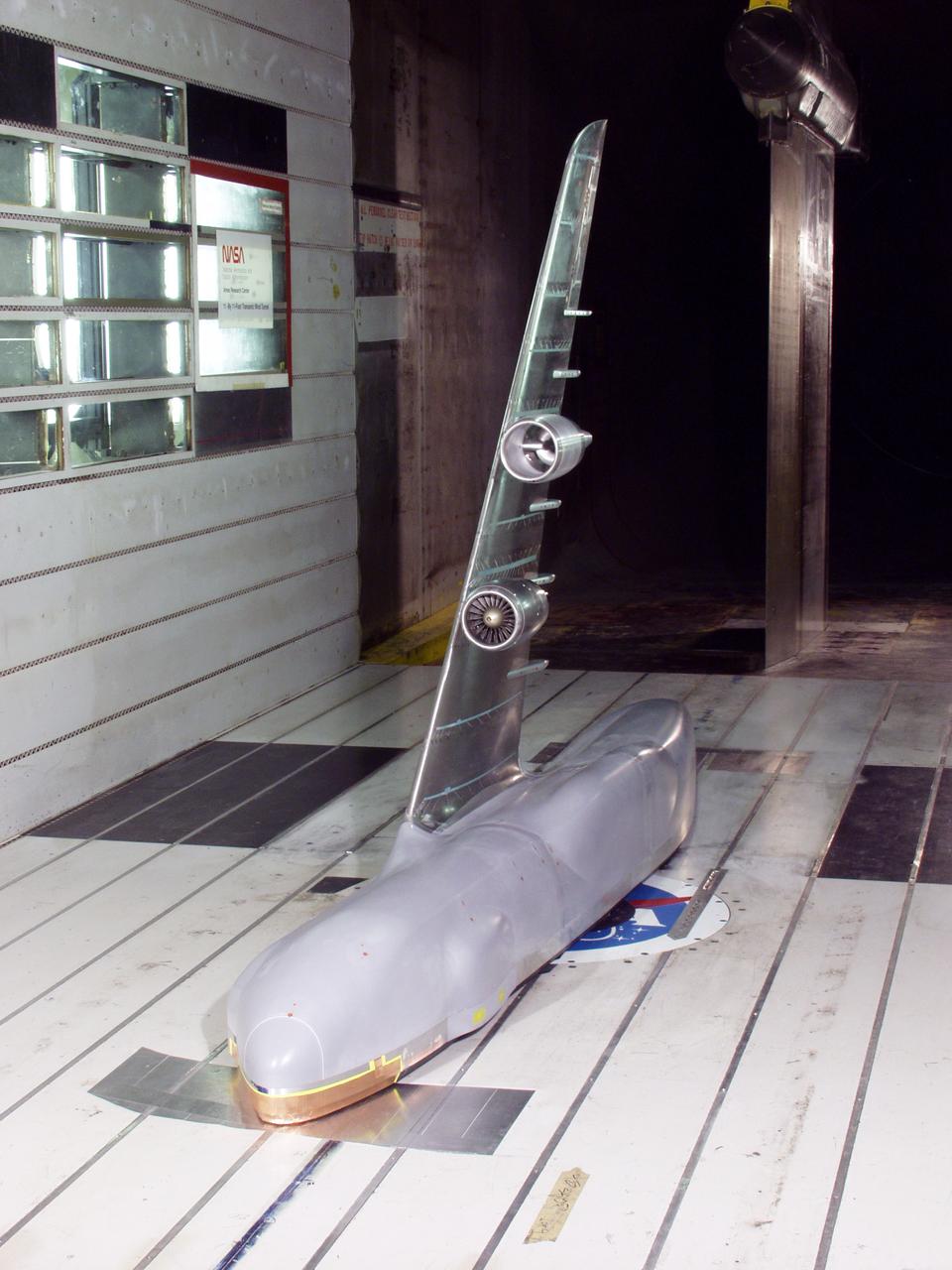
C-5 Re-engineering and Realiability Program semi-span model; 11ft w.t. Test-11-0103; Throught flow nacelle and inboard nacelle with turbine propulsion systems unit
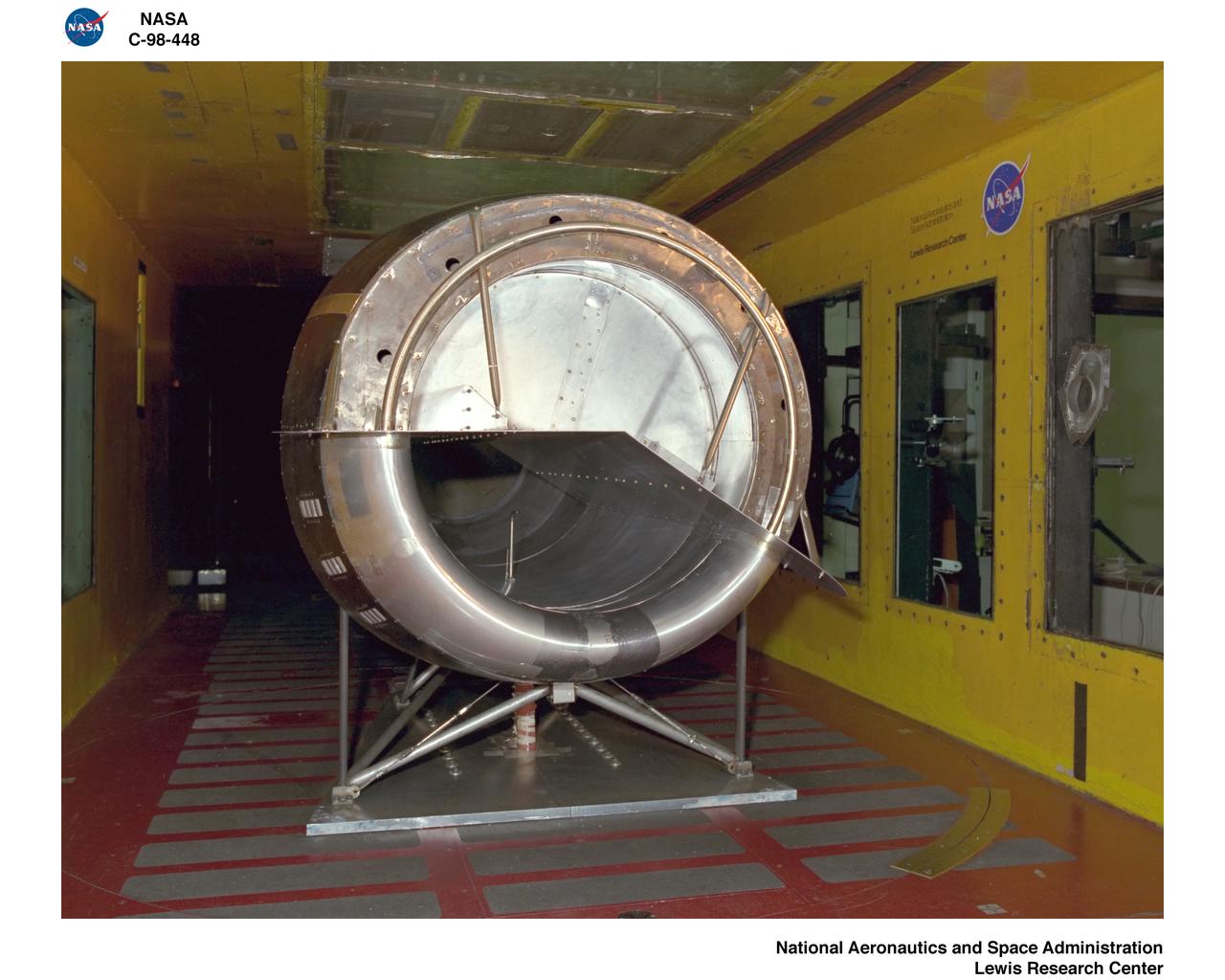
NORDAM INLET NACELLE
NORDAM INLET NACELLE
NORDAM INLET NACELLE
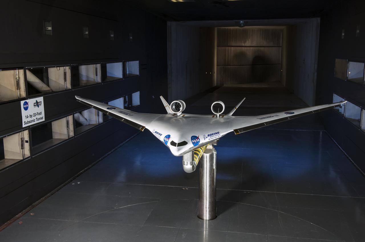
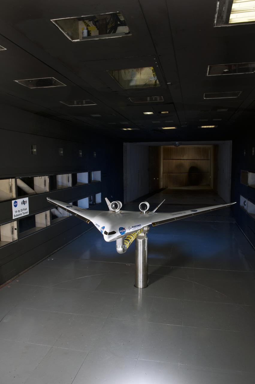
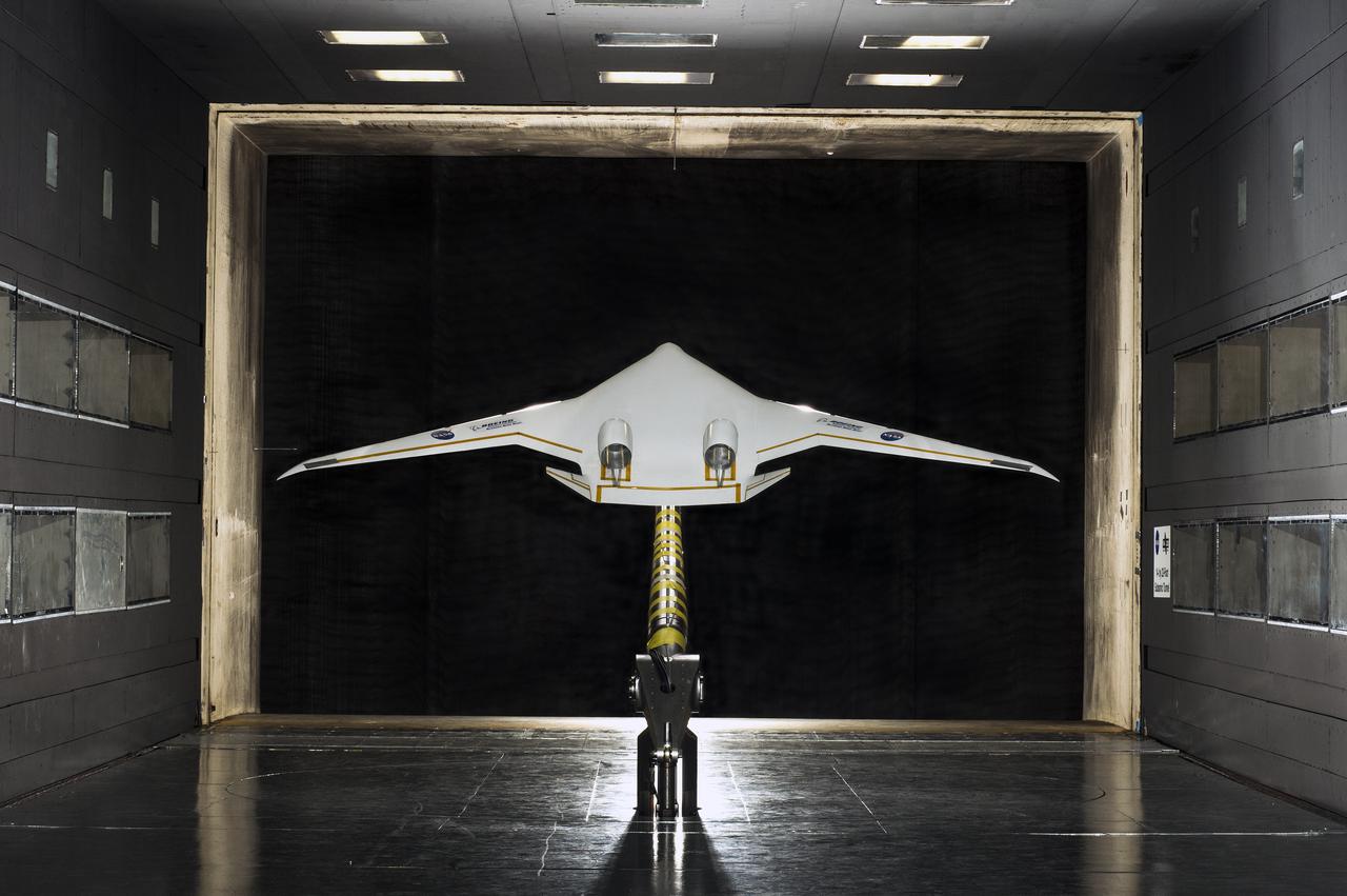
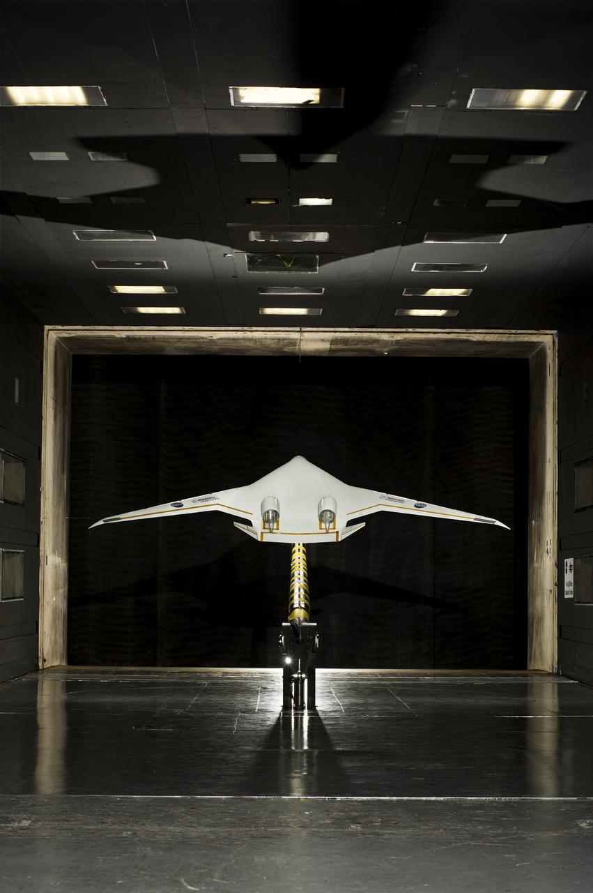
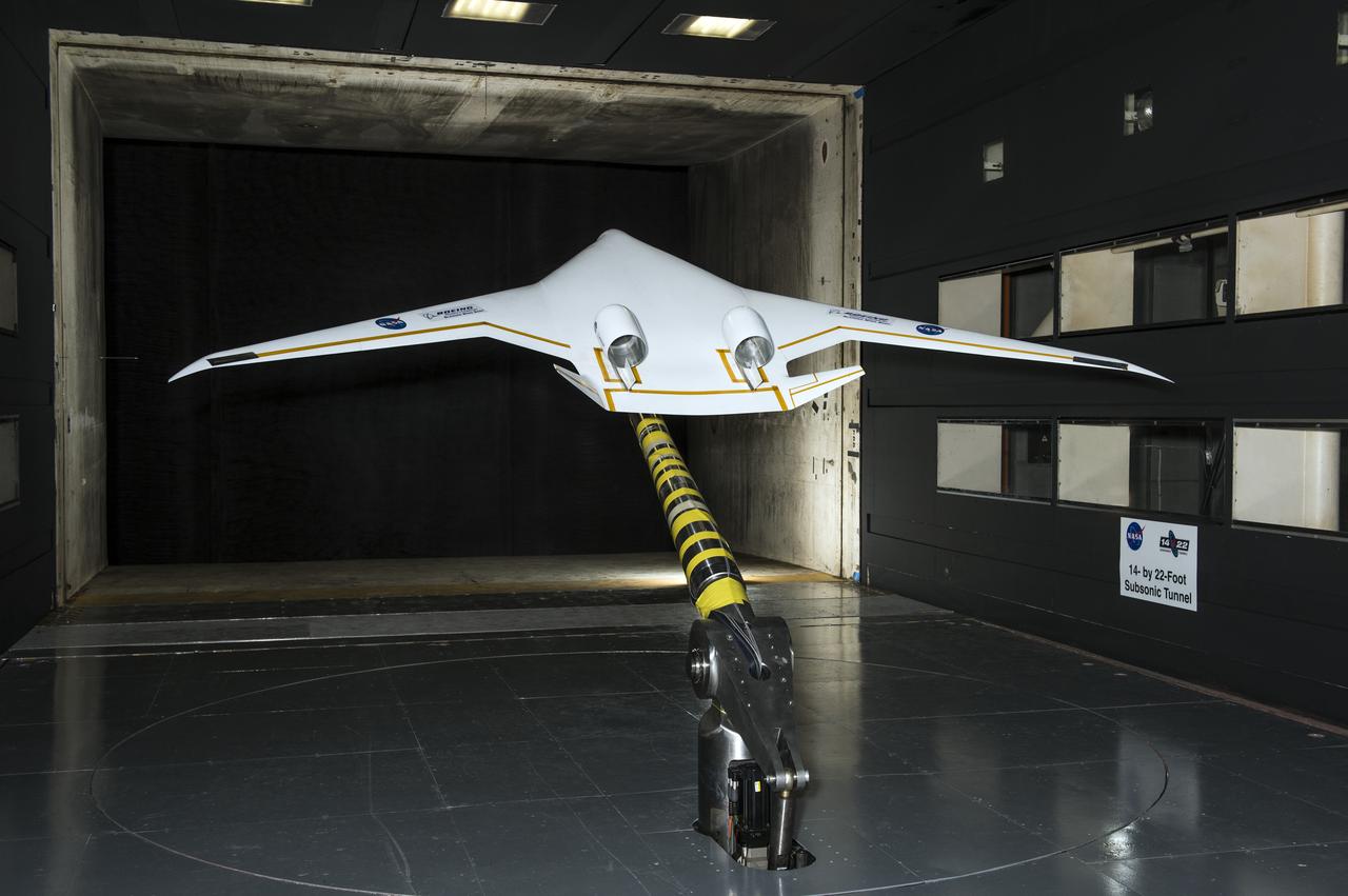
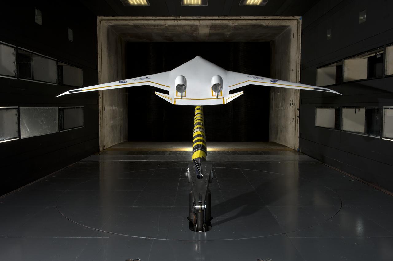
5.75% Scale Boeing BWB-0009G Model in NASA Langley 14x22 Foot Tunnel: Low speed aerodynamics test of BWB model with flow-thru nacelles in Langley 14x22 foot tunnel(test 617)
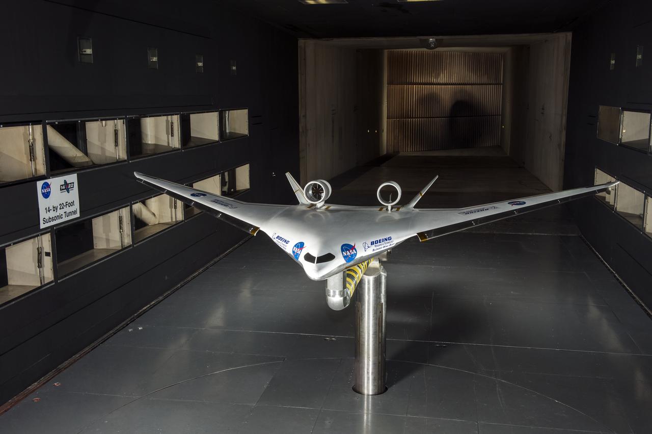
5.75% Scale Boeing BWB-0009G Model in NASA Langley 14x22 Foot Tunnel: Low speed aerodynamics test of BWB model with flow-thru nacelles in Langley 14x22 foot tunnel(test 617)
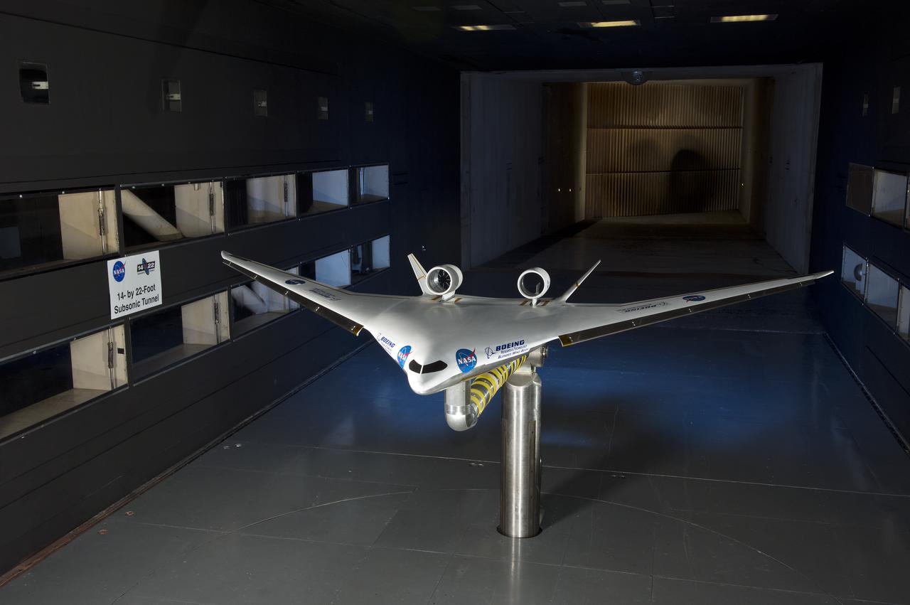
5.75% Scale Boeing BWB-0009G Model in NASA Langley 14x22 Foot Tunnel: Low speed aerodynamics test of BWB model with flow-thru nacelles in Langley 14x22 foot tunnel(test 617)
3/4 front view of model without nacelles on regular struts. Generalized Subsonic Jet Transport model with leading edge and trailing edge blowing BLC in the 40x80 foot wind tunnel at NASA Ames.
5.75% Scale Boeing BWB-0009G Model in NASA Langley 14x22 Foot Tunnel: Low speed aerodynamics test of BWB model with flow-thru nacelles in Langley 14x22 foot tunnel(test 617)
5.75% Scale Boeing BWB-0009G Model in NASA Langley 14x22 Foot Tunnel: Low speed aerodynamics test of BWB model with flow-thru nacelles in Langley 14x22 foot tunnel(test 617)
5.75% Scale Boeing BWB-0009G Model in NASA Langley 14x22 Foot Tunnel: Low speed aerodynamics test of BWB model with flow-thru nacelles in Langley 14x22 foot tunnel(test 617)
AST (Advanced Supersonic Technology) Propulsion Noise Research test on the F-15 model with nacelle in the 40x80ft Subsonic Wind Tunnel at Ames Research Center, Mt View, CA
5.75% Scale Boeing BWB-0009G Model in NASA Langley 14x22 Foot Tunnel: Low speed aerodynamics test of BWB model with flow-thru nacelles in Langley 14x22 foot tunnel(test 617)
5.75% Scale Boeing BWB-0009G Model in NASA Langley 14x22 Foot Tunnel: Low speed aerodynamics test of BWB model with flow-thru nacelles in Langley 14x22 foot tunnel(test 617)
A researcher examines an Advanced Technology Transport model installed in the 8- by 6-Foot Supersonic Wind Tunnel at the National Aeronautics and Space Administration (NASA) Lewis Research Center. The Advanced Technology Transport concept was a 200-person supersonic transport aircraft that could cruise at Mach 0.9 to 0.98 with low noise and pollution outputs. General Electric and Pratt and Whitney responded to NASA Lewis’ call to design a propulsion system for the aircraft. The integration of the propulsion system with the airframe was one of the greatest challenges facing the designers of supersonic aircraft. The aircraft’s flow patterns and engine nacelles could significantly affect the performance of the engines. NASA Lewis researchers undertook a study of this 0.30-scale model of the Advanced Technology Transport in the 8- by 6-foot tunnel. The flow-through nacelles were located near the rear of the fuselage during the initial tests, seen here, and then moved under the wings for ensuing runs. Different engine cowl shapes were also analyzed. The researchers determined that nacelles mounted at the rear of the aircraft produced more efficient airflow patterns during cruising conditions at the desired velocities. The concept of the Advanced Technology Transport, nor any other US supersonic transport, has ever come to fruition. The energy crisis, environmental concerns, and inadequate turbofan technology of the 1970s were among the most significant reasons.
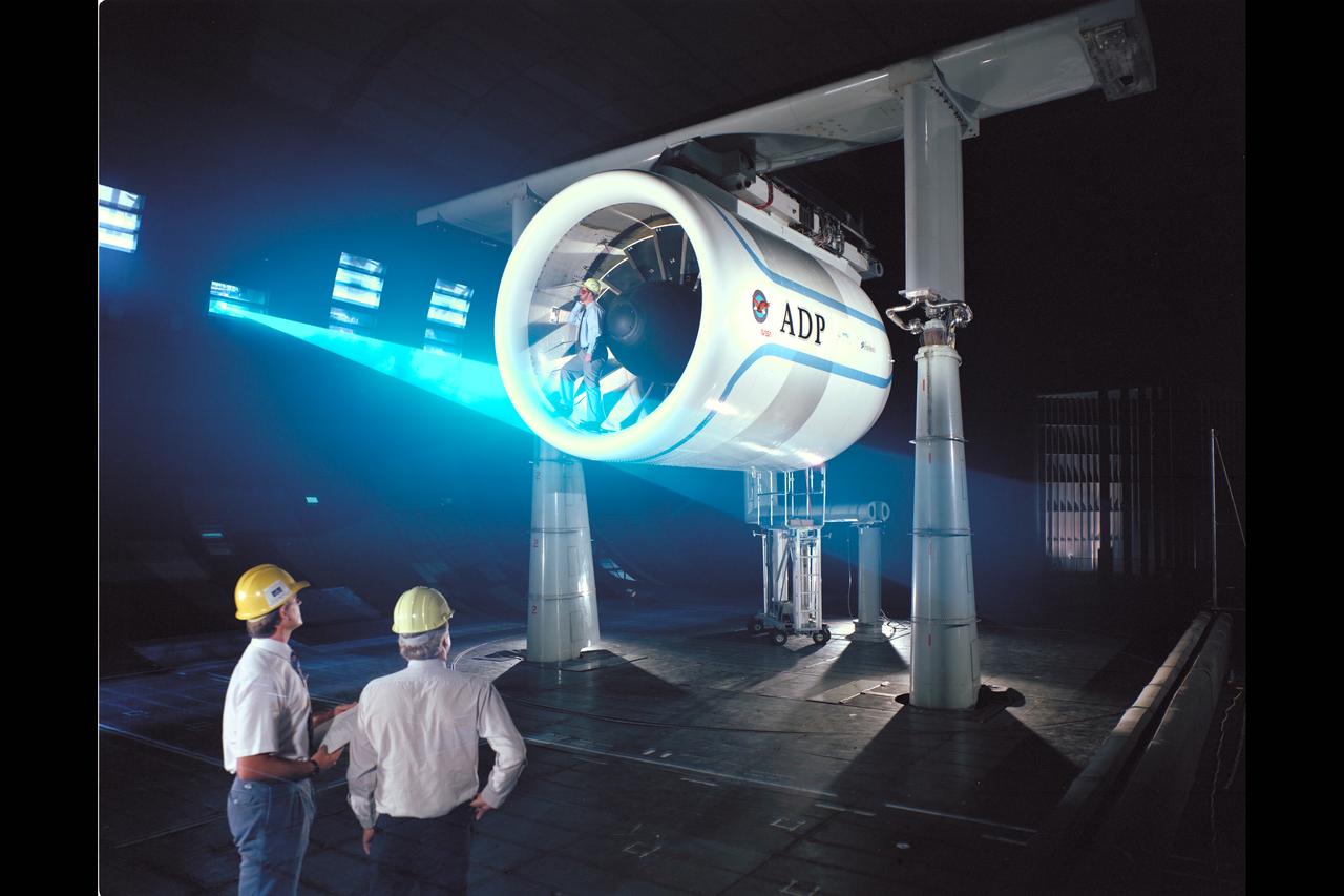
Pratt & Whitney Advanced Ducted Propulsor (ADP) Engine Test-590 in NASA Ames 40x80ft Subsonic Wind Tunnel. The Pratt & Whitney advanced ducted prop (ADP) demonstrator undergoing acoustic and fan performance testing. ADP technology could lead to decreased fuel consumption and noise. Shown here are NASA Ames engineers Peter Zell (left) and Dr Clifton Horne (right) preparing for a laser light sheet for a flow visualization test. Shown standing in the nacelle of the ADP is John Girvin, senior test engineer for Pratt & Whitney.
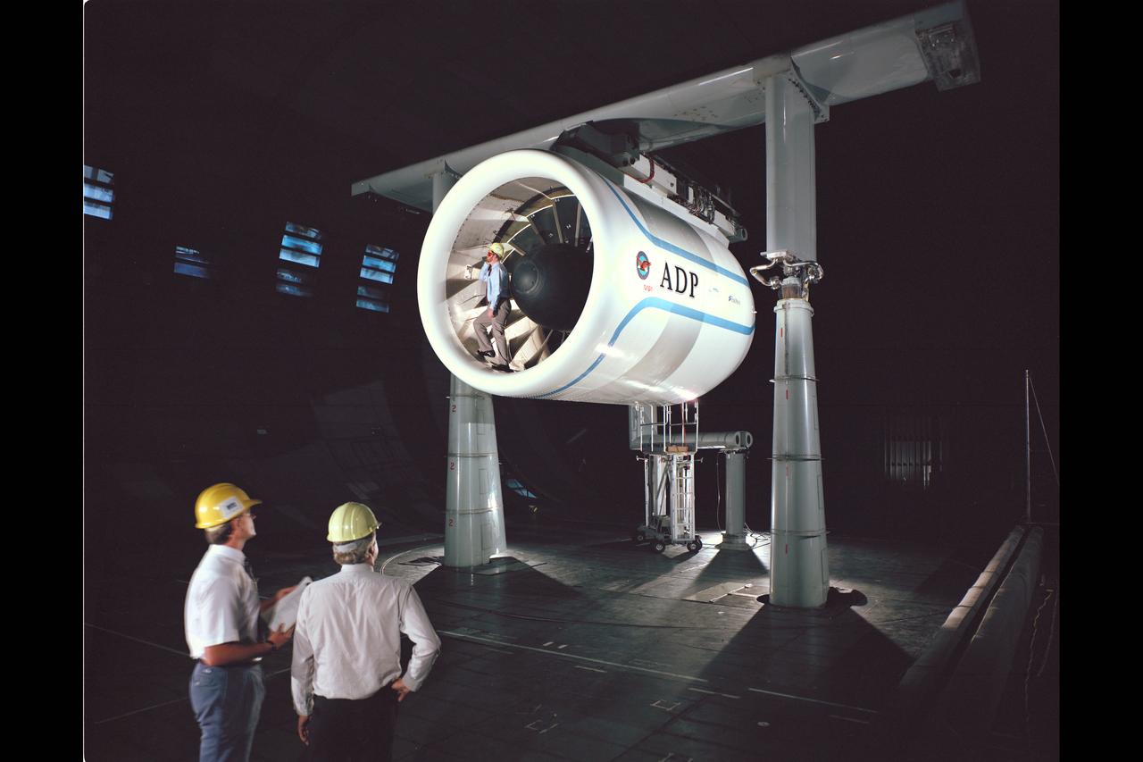
Pratt & Whitney Advanced Ducted Propulsor (ADP) Engine Test-590 in NASA Ames 40x80ft Subsonic Wind Tunnel. The Pratt & Whitney advanced ducted prop (ADP) demonstrator undergoing acoustic and fan performance testing. ADP technology could lead to decreased fuel consumption and noise. Shown here are NASA Ames engineers Peter Zell (left) and Dr Clifton Horne (right) preparing for a laser light sheet for a flow visualization test. Shown standing in the nacelle of the ADP is John Girvin, senior test engineer for Pratt & Whitney.
The Fan Noise Test Facility built at the Lewis Research Center to obtain far-field noise data for the National Aeronautics and Space Administration (NASA) and General Electric Quiet Engine Program. The engine incorporated existing noise reduction methods into an engine of similar power to those that propelled the Boeing 707 or McDonnell-Douglas DC-8 airliner. The new the low-bypass ratio turbofan engines of the 1960s were inherently quieter than their turbojet counterparts, researchers had a better grasp of the noise generation problem, and new acoustic technologies had emerged. Lewis contracted General Electric in 1969 to build and aerodynamically test three experimental engines with 72-inch diameter fans. The engines were then brought to Lewis and tested with an acoustically treated nacelle. This Fan Noise Test Facility was built off of the 10- by 10-Foot Supersonic Wind Tunnel’s Main Compressor and Drive Building. Lewis researchers were able to isolate the fan’s noise during these initial tests by removing the core of the engine. The Lewis test rig drove engines to takeoff tip speeds of 1160 feet per second. The facility was later used to test a series of full-scale model fans and fan noise suppressors to be used with the quiet engine. NASA researchers predicted low-speed single-stage fans without inlet guide vanes and with large spacing between rotors and stators would be quieter. General Electric modified a TF39 turbofan engine by removing the the outer protion of the fan and spacing the blade rows of the inner portion. The tests revealed that the untreated version of the engine generated less noise than was anticipated, and the acoustically treated nacelle substantially reduced engine noise.
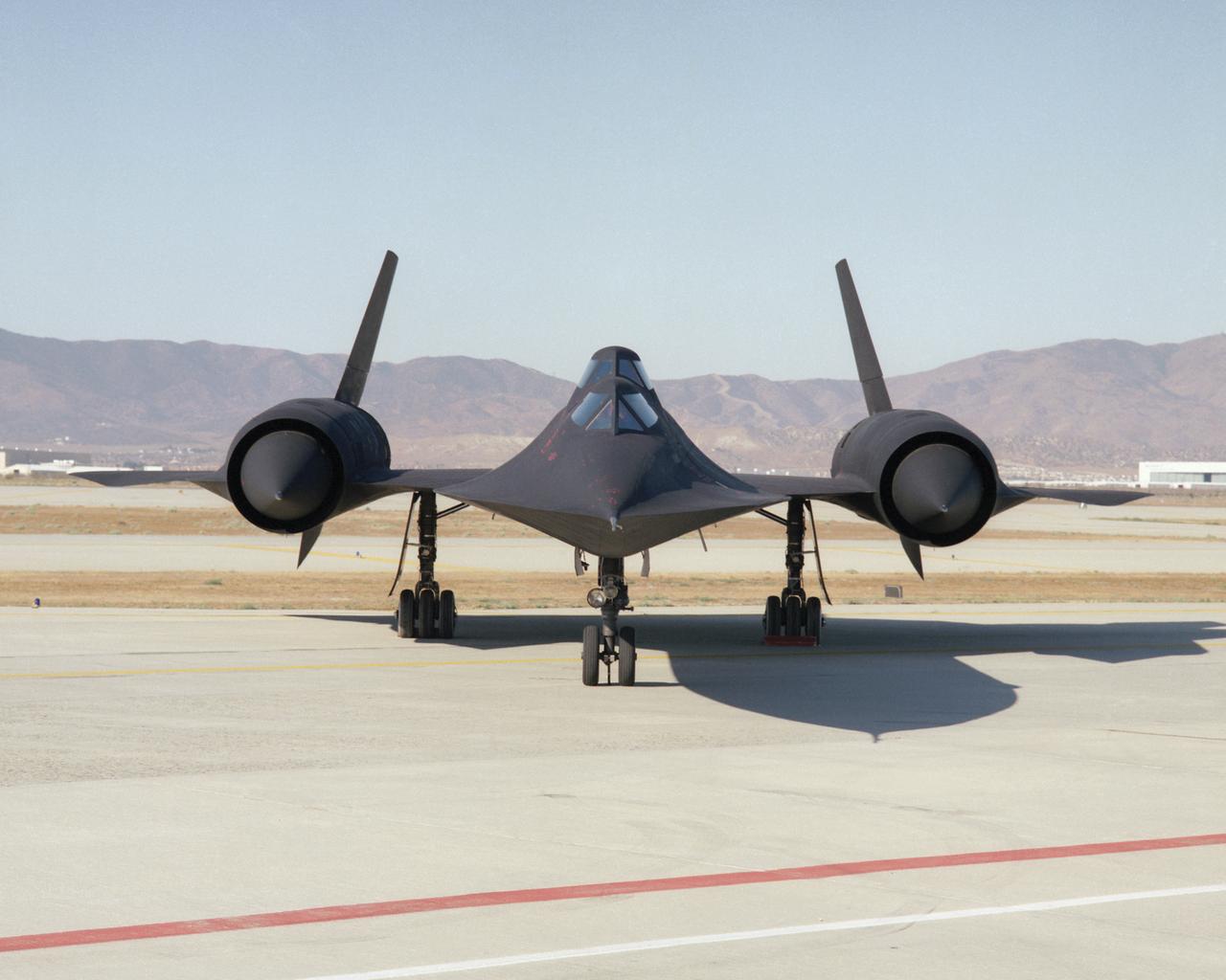
This photo shows a head-on view of NASA's SR-71B, used for pilot proficiency and training, on the ramp at the Air Force's Plant 42 in Palmdale, California, shortly before delivery to the Ames-Dryden Flight Research Facility (later, Dryden Flight Research Center) at Edwards, California. NASA operated two of these unique aircraft, an SR-71A, for high-speed, high altitude research, and this SR- 71B pilot trainer for most of the decade of the 1990s. The "B" model is special because of its raised rear cockpit, which provided a second pilot position so a trainer and an experienced pilot could both see what was going on during flights. The SR-71 was designed and built by the Lockheed Skunk Works, now the Lockheed Martin Skunk Works. Studies have shown that less than 20 percent of the total thrust used to fly at Mach 3 is produced by the basic engine itself. The balance of the total thrust is produced by the unique design of the engine inlet and "moveable spike" system at the front of the engine nacelles, and by the ejector nozzles at the exhaust which burn air compressed in the engine bypass system. Data from the SR-71 high speed research program will be used to aid designers of future supersonic/hypersonic aircraft and propulsion systems, including a high speed civil transport.
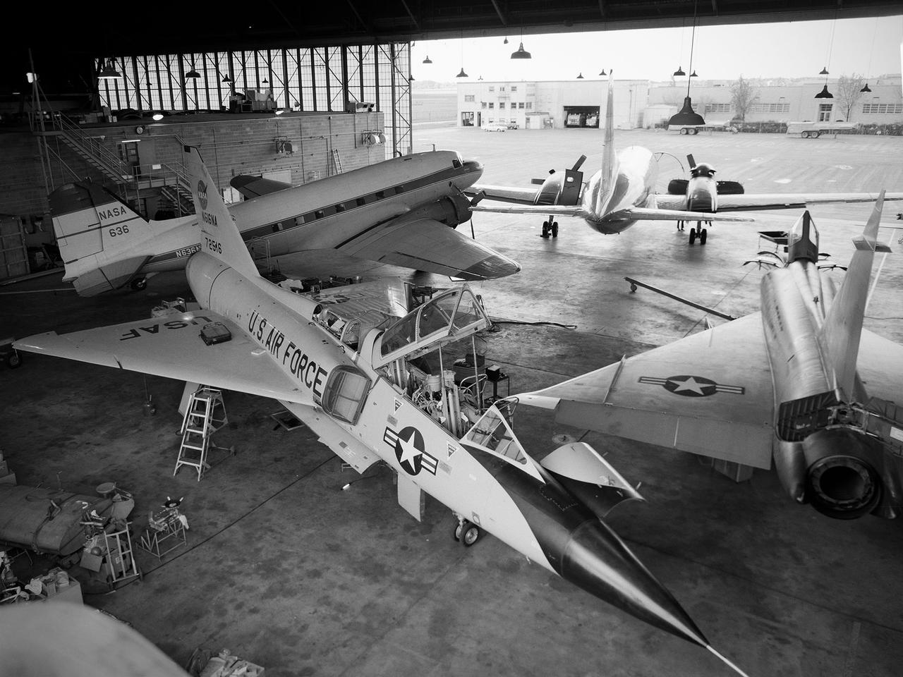
Several aircraft parked inside the Flight Research Building, or hangar, at the National Aeronautics and Space Administration (NASA) Lewis Research Center in Cleveland, Ohio. A Convair F-106B Delta Dart is in the foreground, a Convair F-102A Delta Dagger is to the right, a Douglas DC-3 is in the back to left, and a Convair T-29 is in background. Lewis’ Martin B-57B Canberra is not seen in this photograph. The F-102A had just been acquired by Lewis to serve as a chase plane for the F-106B. The Lewis team removed the weapons system and 700 pounds of wire from the F-106B when it was acquired on October 20, 1966. The staff cut holes in the wings and modified the elevons to mount the test nacelles. A 228-gallon fuel tank was installed in the missile bay, and the existing wing tanks were used for instrumentation. This photograph contains a rare view of the Block House, seen to the left of the aircraft. Lewis acquired three large developmental programs in 1962—the Centaur and Agena rockets and the M-1 engine. The center was short on office space at the time, and its flight research program was temporarily on the wane. Lewis management decided to construct a large cinderblock structure inside one half of the hangar to house the new personnel. This structure was used until 1965 when the new Developmental Engineering Building was built. The Block House was eventually torn down in 1973.
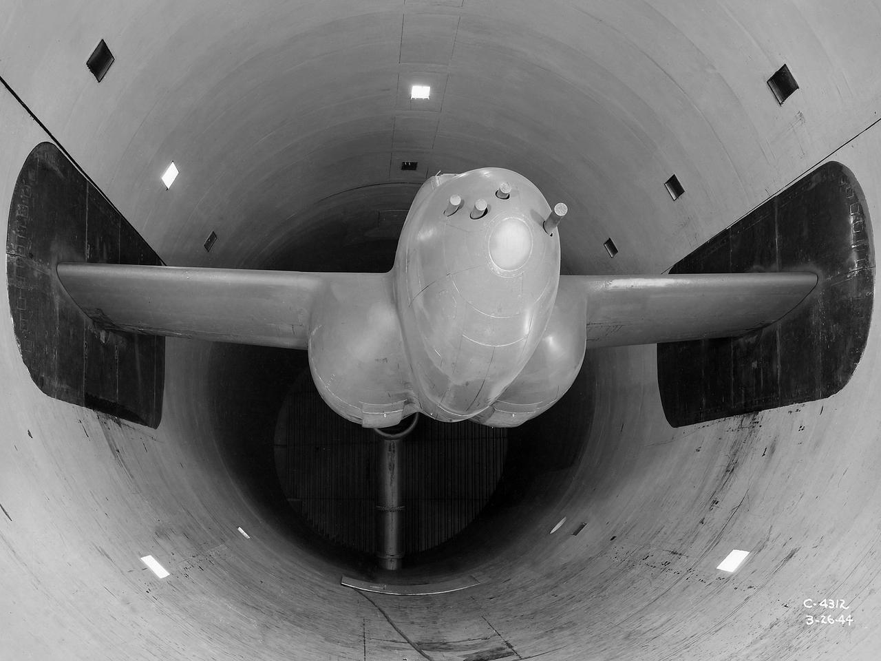
The Altitude Wind Tunnel (AWT) was the National Advisory Committee for Aeronautics (NACA) Aircraft Engine Research Laboratory’s largest and most important test facility in the 1940s. The AWT employed massive cooling and exhaust systems to simulate conditions found at high altitudes. The facility was originally designed to test large piston engines in a simulated flight environment. The introduction of the turbojet during the tunnel’s construction, however, changed the facility’s focus before it became operational. Its first test program was a study of the Bell YP–59A Airacomet and its General Electric I–16 turbojets. The Airacomet was the United States’ first attempt to build a jet aircraft. 1600-horsepower centrifugal engines based on an early design by British engineer Frank Whittle were incorporated into an existing Bell airframe. In October 1942 the Airacomet was secretly test flown in the California desert. The aircraft’s performance was limited, however, and the NACA was asked to study the engines in the AWT. The wind tunnel’s 20-foot-diameter test section was large enough to accommodate entire aircraft with its wing tips and tail removed. The I-16 engines were studied exhaustively in early 1944. They first analyzed the engines in their original configuration and then implemented a boundary layer removal duct, a new nacelle inlet, and new cooling seals. Tests of the modified version showed that the improved distribution of airflow increased the I–16’s performance by 25 percent. The Airacomet never overcame some of its inherent design issues, but the AWT went on to study nearly every emerging US turbojet model during the next decade.
The secret test of the Bell YP–59A Airacomet in the spring of 1944 was the first investigation in the National Advisory Committee for Aeronautics (NACA) Aircraft Engine Research Laboratory’s new Altitude Wind Tunnel (AWT). The Airacomet, powered by two General Electric I–A centrifugal turbojets, was the first US jet aircraft. The Airacomet’s 290-miles per hour speed, however, was dwarfed by the German Messerschmitt Me-262 Schwalbe’s 540 miles per hour. In 1941 and 1942 General Electric built the first US jet engines based on technical drawings from British engineer Frank Whittle. Bell Aircraft was contracted to produce an airframe to incorporate the new engines. The result was the Bell XP–59A Airacomet. The aircraft made its first flight over Muroc Lake, California, on October 2, 1942. The aircraft continued to struggle over the next year and the NACA was asked to test it in the new AWT. A Bell YP–59A was flown from the Bell plant in Buffalo to Cleveland by Bob Stanley, who had piloted the first successful flight of the XP–59A at Muroc in 1942. The wing tips and tail were cut from the aircraft so that it would fit into the AWT’s test section. The study first analyzed the engines in their original configuration and then implemented a boundary layer removal duct, a new nacelle inlet, and new cooling seals. Tests of the modified version showed that the improved airflow distribution increased the I–16’s performance by 25 percent. Despite the improved speed, the aircraft was not stable enough to be used in combat, and the design was soon abandoned.
A technician checks a 0.25-scale engine model of a Vought Corporation V-530 engine in the test section of the 10- by 10-Foot Supersonic Wind Tunnel at the National Aeronautics and Space Administration (NASA) Lewis Research Center. Vought created a low-drag tandem-fan Vertical/Short and Takeoff and Landing (V/STOL) engine in the mid-1970s, designated as the V-530. The first fan on the tandem-fan engine was supplied with air through a traditional subsonic inlet, seen on the lower front of the engine. The air was exhausted through the nacelle during normal flight and directed down during takeoffs. The rear fan was supplied by the oval-shaped top inlet during all phases of the flight. The second fan exhausted its air through a rear vectorable nozzle. NASA Lewis and Vought partnered in the late 1970s to collect an array of inlet and nozzle design information on the tandem fan engines for the Navy. Vought created this .25-scale model of the V-530 for extensive testing in Lewis' 10- by 10-foot tunnel. During an early series of tests, the front fan was covered, and a turbofan simulator was used to supply air to the rear fan. The researchers then analyzed the performance of only the front fan inlet. During the final series of tests, the flow from the front fan was used to supply airflow to the rear fan. The researchers studied the inlet's recovery, distortion, and angle-of-attack limits over various flight conditions.

The XV-15 tilt rotor ships #1 and #2 parked on the NASA Dryden Flight Research Center ramp. The XV-15s, manufactured by Bell, were involved in limited research at Dryden in 1980 and 1981. The development of the XV-15 Tiltrotor research aircraft was initiated in 1973 with joint Army/NASA funding as a "proof of concept", or "technology demonstrator" program, with two aircraft being built by Bell Helicopter Textron (BHT) in 1977. The aircraft are powered by twin Lycoming T-53 turboshaft engines that are connected by a cross-shaft and drive three-bladed, 25 ft diameter metal rotors (the size extensively tested in a wind tunnel). The engines and main transmissions are located in wingtip nacelles to minimize the operational loads on the cross-shaft system and, with the rotors, tilt as a single unit. For takeoff, the proprotors and their engines are used in the straight-up position where the thrust is directed downward. The XV-15 then climbs vertically into the air like a helicopter. In this VTOL mode, the vehicle can lift off and hover for approximately one hour. Once off the ground, the XV-15 has the ability to fly in one of two different modes. It can fly as a helicopter, in the partially converted airplane mode. The XV-15 can also then convert from the helicopter mode to the airplane mode. This is accomplished by continuous rotation of the proprotors from the helicopter rotor position to the conventional airplane propeller position. During the ten to fifteen second conversion period, the aircraft speed increases and lift is transferred from the rotors to the wing. To land, the proprotors are rotated up to the helicopter rotor position and flown as a helicopter to a vertical landing.