NASA’s Cross Flow Attenuated Natural Laminar Flow (CATNLF) scale model completes its first major milestone – high-speed taxi test – Tuesday, Jan. 12, 2026, at Edwards Air Force Base in California. NASA’s F-15 research aircraft, with the 3-foot-tall test article mounted on its underside, reached speeds of approximately 144 mph during testing. If successful, the technology could be applied to future commercial aircraft to improve efficiency and potentially reduce fuel consumption.
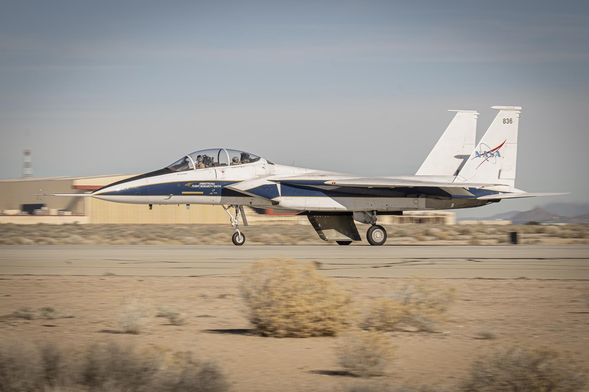
NASA’s Cross Flow Attenuated Natural Laminar Flow (CATNLF) scale model completes its first major milestone – high-speed taxi test – Tuesday, Jan. 12, 2026, at Edwards Air Force Base in California. NASA’s F-15 research aircraft, with the 3-foot-tall test article mounted on its underside, reached speeds of approximately 144 mph during testing. If successful, the technology could be applied to future commercial aircraft to improve efficiency and potentially reduce fuel consumption.
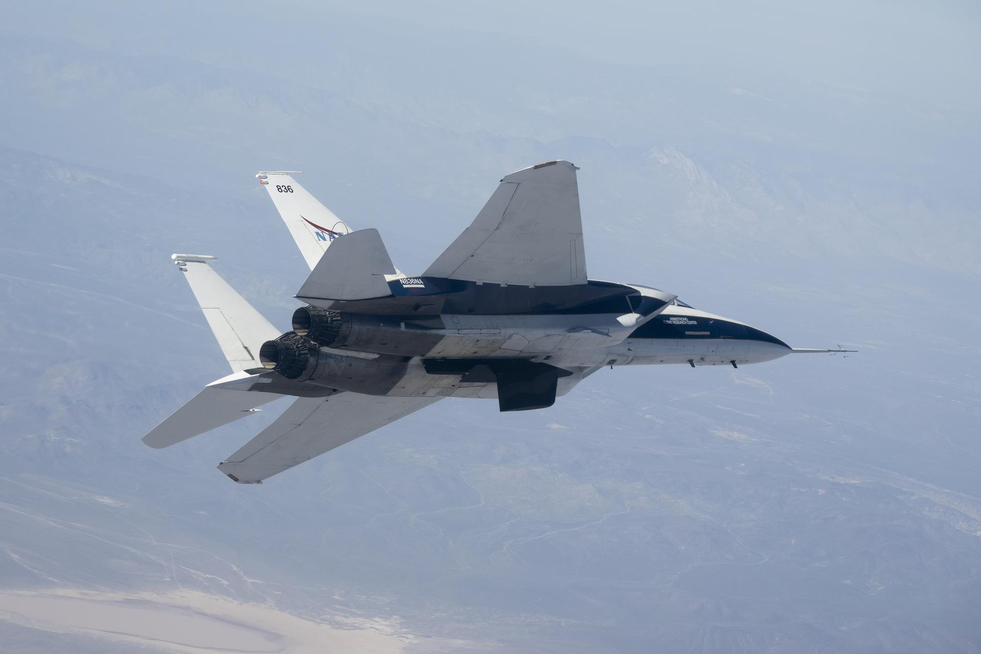
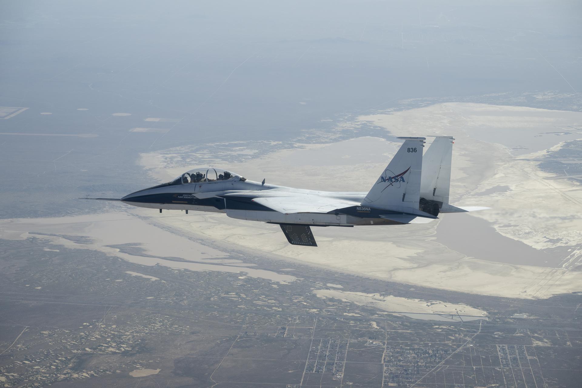
NASA’s Crossflow Attenuated Natural Laminar Flow (CATNLF) scale-model wing flies on a NASA F-15 research jet during a test flight from NASA’s Armstrong Flight Research Center in Edwards, California. The CATNLF technology is designed to maintain smooth airflow, known as laminar flow. NASA will continue flight tests to collect data that validates the CATNLF design and its potential to improve laminar flow, reducing drag and lowering fuel costs for future commercial aircraft.
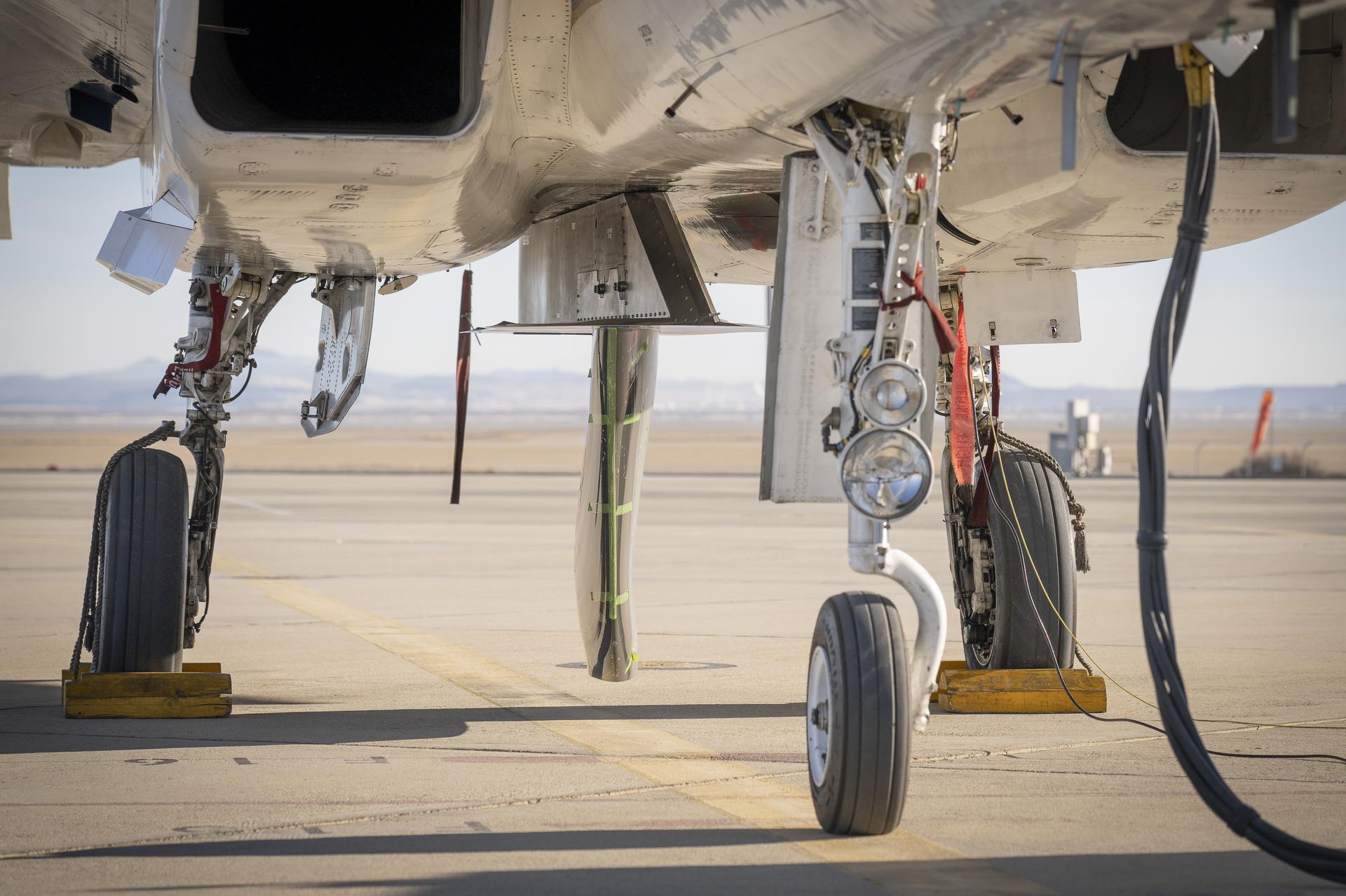
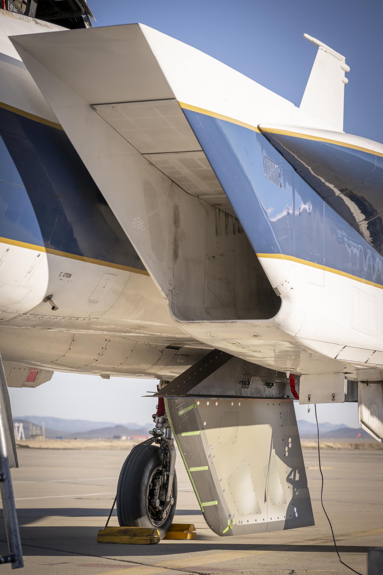
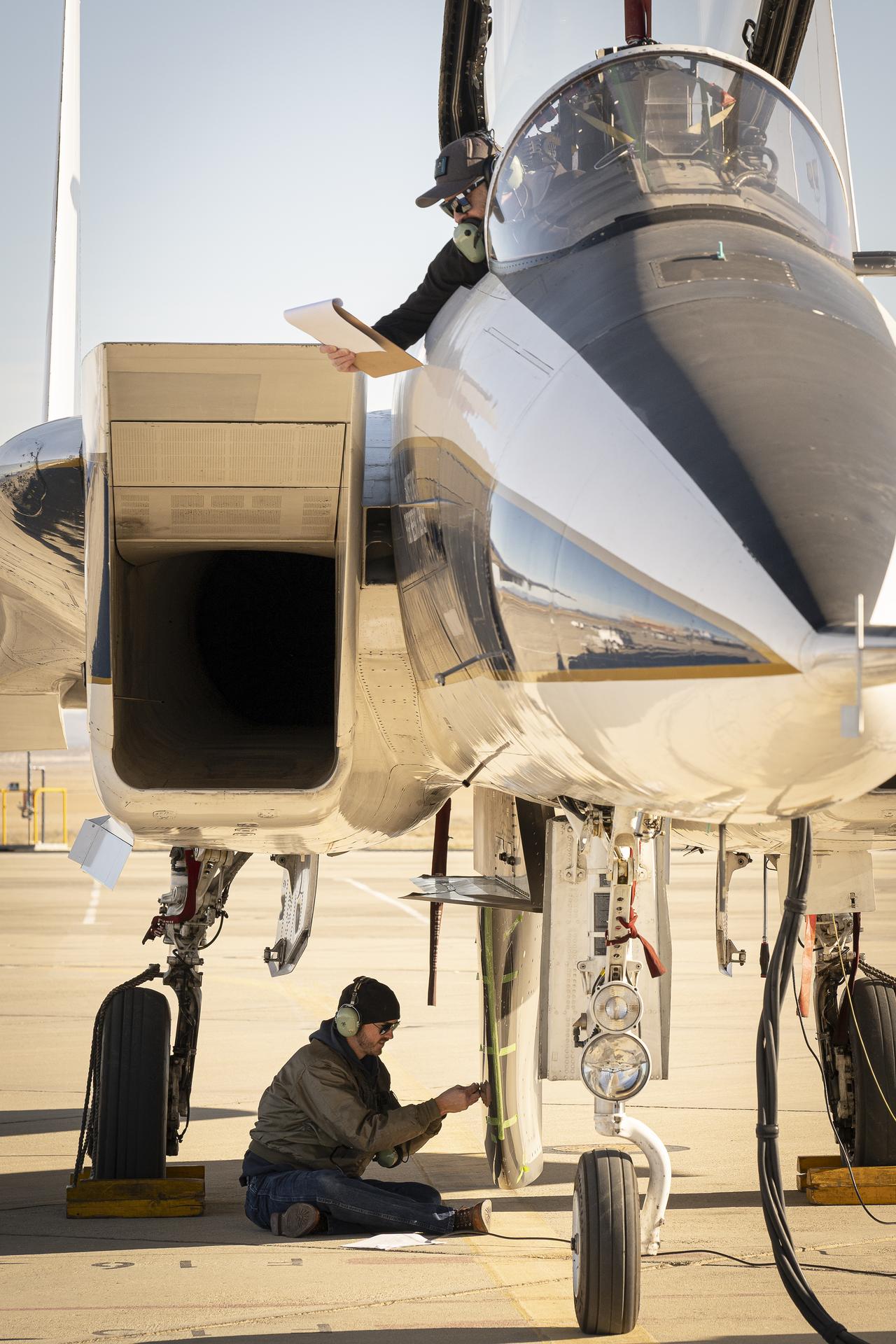
NASA’s Cross Flow Attenuated Natural Laminar Flow test article is mounted beneath the agency’s F-15 research aircraft ahead of the design’s high-speed taxi test on Tuesday, Jan. 12, 2026, at NASA’s Armstrong Flight Research Center in Edwards, California. The 3-foot-tall scale model is designed to increase a phenomenon known as laminar flow and reduce drag, improving efficiency in large, swept wings like those found on most commercial aircraft.
NASA’s Cross Flow Attenuated Natural Laminar Flow test article is mounted beneath the agency’s F-15 research aircraft ahead of the design’s high-speed taxi test on Tuesday, Jan. 12, 2026, at NASA’s Armstrong Flight Research Center in Edwards, California. The 3-foot-tall scale model is designed to increase a phenomenon known as laminar flow and reduce drag, improving efficiency in large, swept wings like those found on most commercial aircraft.
NASA’s Cross Flow Attenuated Natural Laminar Flow test article is mounted beneath the agency’s F-15 research aircraft ahead of the design’s high-speed taxi test on Tuesday, Jan. 12, 2026, at NASA’s Armstrong Flight Research Center in Edwards, California. The 3-foot-tall scale model is designed to increase a phenomenon known as laminar flow and reduce drag, improving efficiency in large, swept wings like those found on most commercial aircraft.
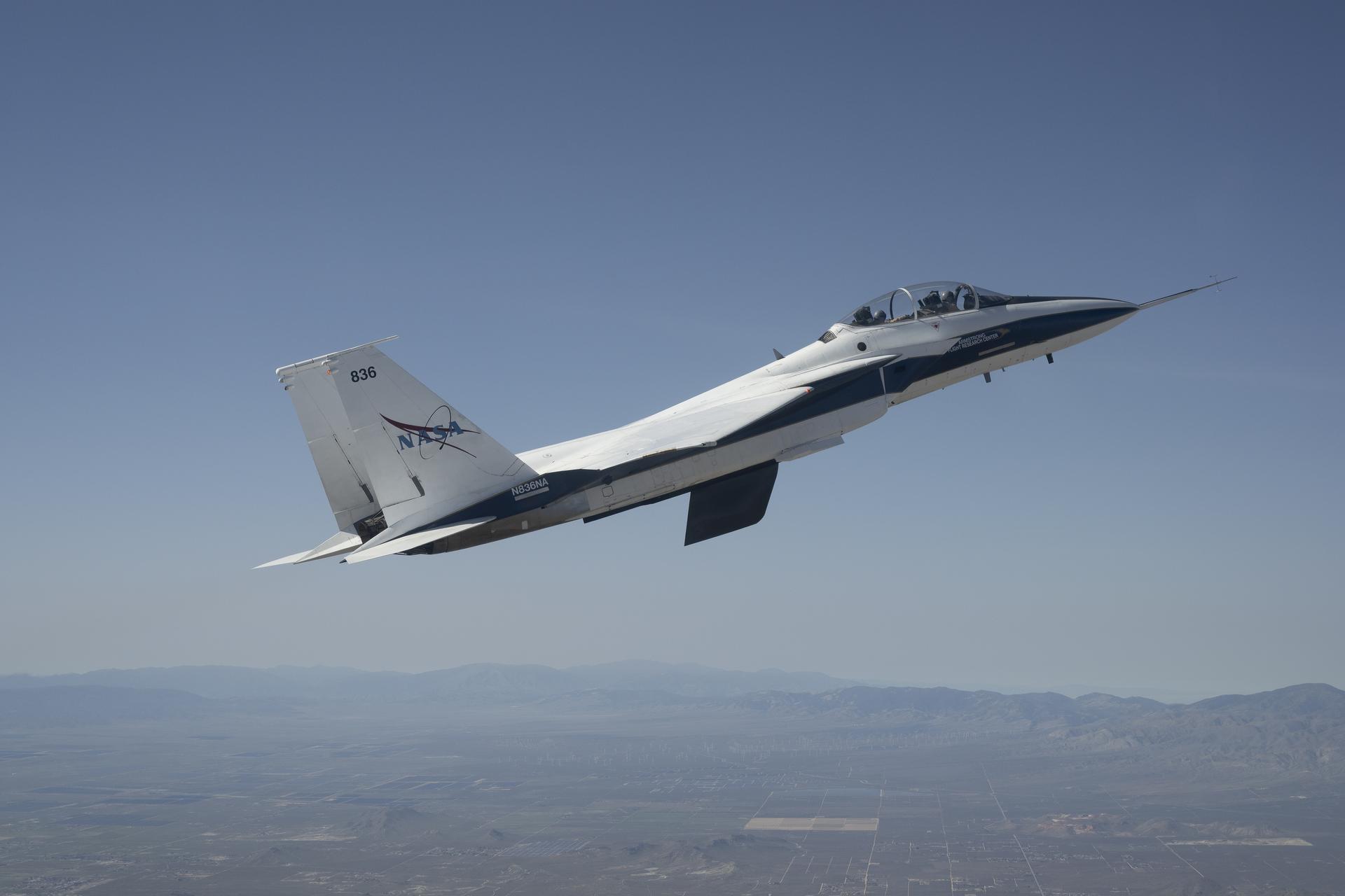
NASA’s Crossflow Attenuated Natural Laminar Flow (CATNLF) scale-model wing flies for the first time on a NASA F-15 research jet during a test flight from NASA’s Armstrong Flight Research Center in Edwards, California. The 75-minute flight confirmed the aircraft could maneuver safely with the approximately 3-foot-tall test article mounted beneath it. NASA will continue flight tests to collect data that validates the CATNLF design and its potential to improve laminar flow, reducing drag and lowering fuel costs for future commercial aircraft.
NASA’s Crossflow Attenuated Natural Laminar Flow (CATNLF) scale-model wing flies for the first time on a NASA F-15 research jet during a test flight from NASA’s Armstrong Flight Research Center in Edwards, California. The 75-minute flight confirmed the aircraft could maneuver safely with the approximately 3-foot-tall test article mounted beneath it. NASA will continue flight tests to collect data that validates the CATNLF design and its potential to improve laminar flow, reducing drag and lowering fuel costs for future commercial aircraft.
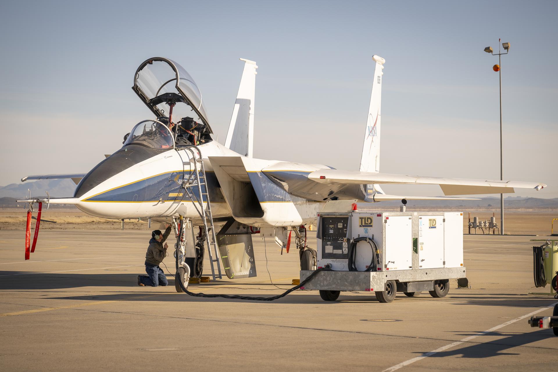
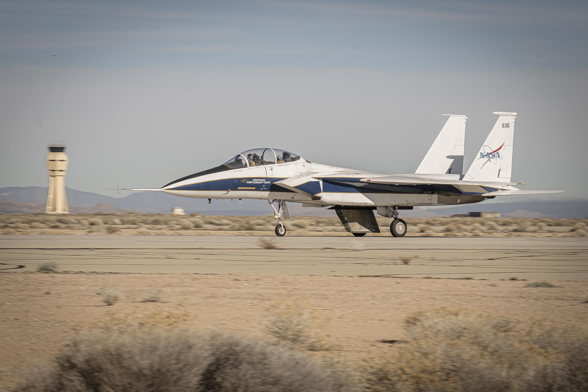
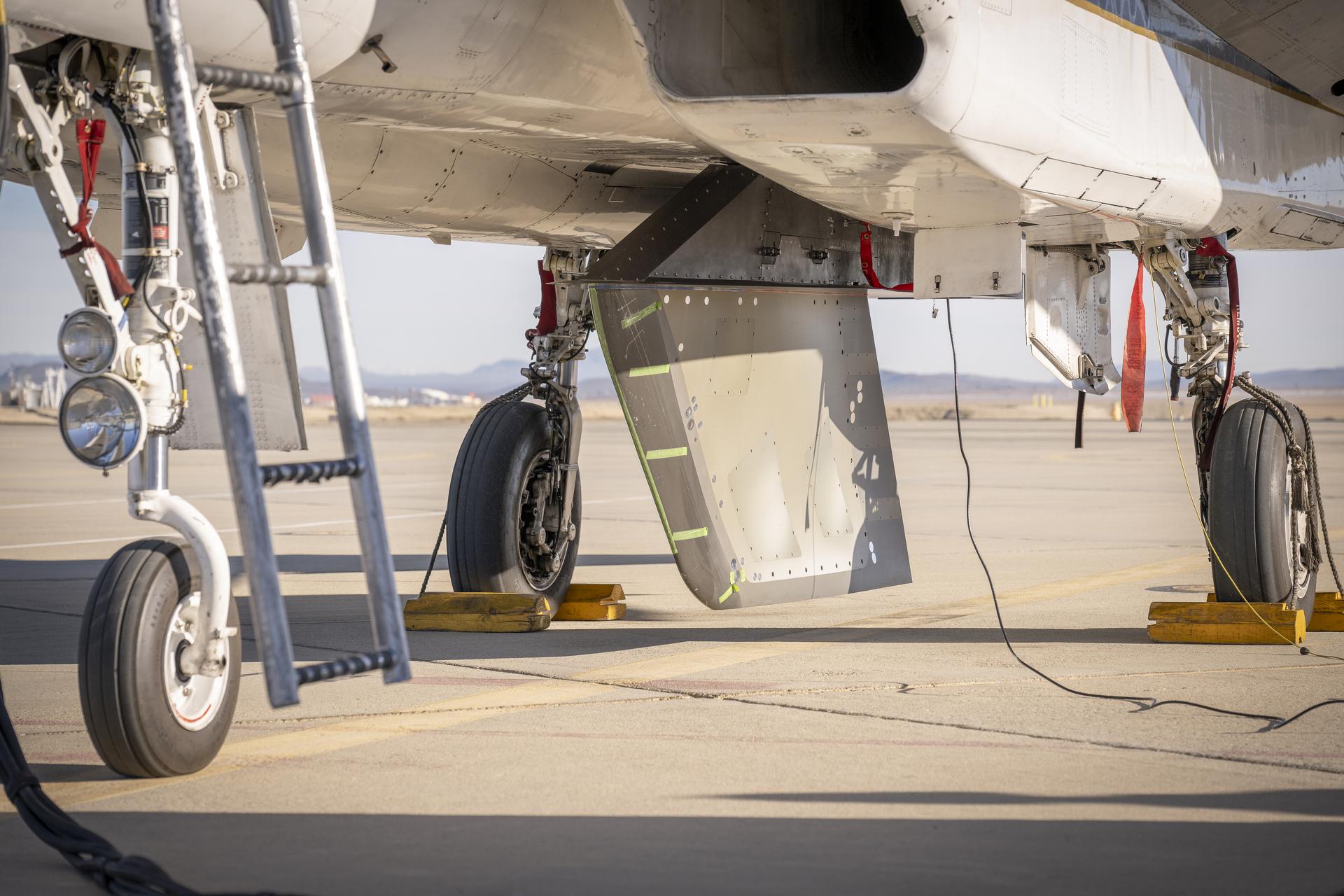
NASA ground crew prepares the agency’s F-15 research aircraft and Cross Flow Attenuated Natural Laminar Flow (CATNLF) test article ahead of its first high-speed taxi test on Tuesday, Jan. 12, 2026, at NASA’s Armstrong Flight Research Center in Edwards, California. The CATNLF design aims to reduce drag on wing surfaces to improve efficiency and, in turn, reduce fuel burn.
NASA ground crew prepares the agency’s F-15 research aircraft and Cross Flow Attenuated Natural Laminar Flow (CATNLF) test article ahead of its first high-speed taxi test on Tuesday, Jan. 12, 2026, at NASA’s Armstrong Flight Research Center in Edwards, California. The CATNLF design aims to reduce drag on wing surfaces to improve efficiency and, in turn, reduce fuel burn.
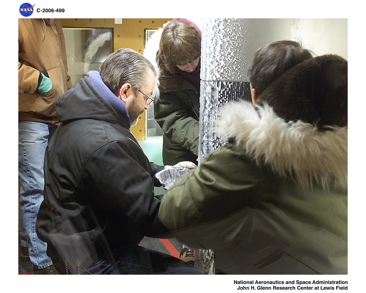
Super Large Droplet (SLD) icing test on a 36 foot cord Natural Laminar Flow wing shape
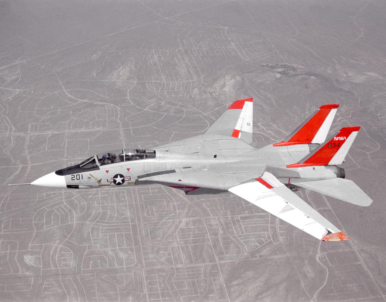
NASA 834, an F-14 Navy Tomcat, seen here in flight, was used at Dryden in 1986 and 1987 in a program known as the Variable-Sweep Transition Flight Experiment (VSTFE). This program explored laminar flow on variable sweep aircraft at high subsonic speeds. An F-14 aircraft was chosen as the carrier vehicle for the VSTFE program primarily because of its variable-sweep capability, Mach and Reynolds number capability, availability, and favorable wing pressure distribution. The variable sweep outer-panels of the F-14 aircraft were modified with natural laminar flow gloves to provide not only smooth surfaces but also airfoils that can produce a wide range of pressure distributions for which transition location can be determined at various flight conditions and sweep angles. Glove I, seen here installed on the upper surface of the left wing, was a "cleanup" or smoothing of the basic F-14 wing, while Glove II was designed to provide specific pressure distributions at Mach 0.7. Laminar flow research continued at Dryden with a research program on the NASA 848 F-16XL, a laminar flow experiment involving a wing-mounted panel with millions of tiny laser cut holes drawing off turbulent boundary layer air with a suction pump.
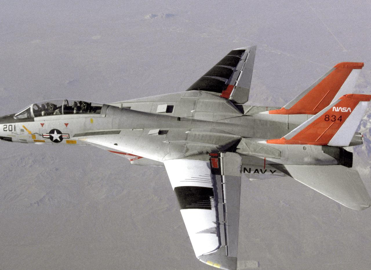
NASA 834, an F-14 Navy Tomcat, seen here in flight, was used at Dryden in 1986 and 1987 in a program known as the Variable-Sweep Transition Flight Experiment (VSTFE). This program explored laminar flow on variable sweep aircraft at high subsonic speeds. An F-14 aircraft was chosen as the carrier vehicle for the VSTFE program primarily because of its variable-sweep capability, Mach and Reynolds number capability, availability, and favorable wing pressure distribution. The variable sweep outer-panels of the F-14 aircraft were modified with natural laminar flow gloves to provide not only smooth surfaces but also airfoils that can produce a wide range of pressure distributions for which transition location can be determined at various flight conditions and sweep angles. Glove I, seen here installed on the upper surface of the left wing, was a "cleanup" or smoothing of the basic F-14 wing, while Glove II was designed to provide specific pressure distributions at Mach 0.7. Laminar flow research continued at Dryden with a research program on the NASA 848 F-16XL, a laminar flow experiment involving a wing-mounted panel with millions of tiny laser cut holes drawing off turbulent boundary layer air with a suction pump.
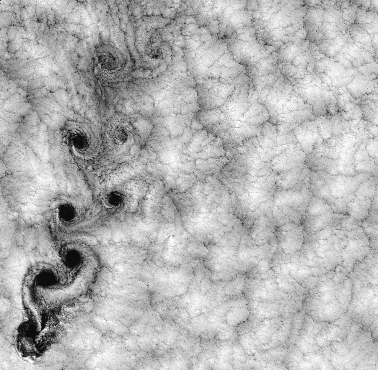
NASA image acquired September 15, 1999 This Landsat 7 image of clouds off the Chilean coast near the Juan Fernandez Islands (also known as the Robinson Crusoe Islands) on September 15, 1999, shows a unique pattern called a “von Karman vortex street.” This pattern has long been studied in the laboratory, where the vortices are created by oil flowing past a cylindrical obstacle, making a string of vortices only several tens of centimeters long. Study of this classic “flow past a circular cylinder” has been very important in the understanding of laminar and turbulent fluid flow that controls a wide variety of phenomena, from the lift under an aircraft wing to Earth’s weather. Here, the cylinder is replaced by Alejandro Selkirk Island (named after the true “Robinson Crusoe,” who was stranded here for many months in the early 1700s). The island is about 1.5 km in diameter, and rises 1.6 km into a layer of marine stratocumulus clouds. This type of cloud is important for its strong cooling of the Earth’s surface, partially counteracting the Greenhouse warming. An extended, steady equatorward wind creates vortices with clockwise flow off the eastern edge and counterclockwise flow off the western edge of the island. The vortices grow as they advect hundreds of kilometers downwind, making a street 10,000 times longer than those made in the laboratory. Observing the same phenomenon extended over such a wide range of sizes dramatizes the “fractal” nature of atmospheric convection and clouds. Fractals are characteristic of fluid flow and other dynamic systems that exhibit “chaotic” motions. Both clockwise and counter-clockwise vortices are generated by flow around the island. As the flow separates from the island’s leeward (away from the source of the wind) side, the vortices “swallow” some of the clear air over the island. (Much of the island air is cloudless due to a local “land breeze” circulation set up by the larger heat capacity of the waters surrounding the island.) The “swallowed” gulps of clear island air get carried along within the vortices, but these are soon mixed into the surrounding clouds. Landsat is unique in its ability to image both the small-scale eddies that mix clear and cloudy air, down to the 30 meter pixel size of Landsat, but also having a wide enough field-of-view, 180 km, to reveal the connection of the turbulence to large-scale flows such as the subtropical oceanic gyres. Landsat 7, with its new onboard digital recorder, has extended this capability away from the few Landsat ground stations to remote areas such as Alejandro Island, and thus is gradually providing a global dynamic picture of evolving human-scale phenomena. For more details on von Karman vortices, refer to <a href="http://climate.gsfc.nasa.gov/~cahalan" rel="nofollow">climate.gsfc.nasa.gov/~cahalan</a>. Image and caption courtesy Bob Cahalan, NASA GSFC Instrument: Landsat 7 - ETM+ Credit: NASA/GSFC/Landsat <b><a href="http://www.nasa.gov/centers/goddard/home/index.html" rel="nofollow">NASA Goddard Space Flight Center</a></b> enables NASA’s mission through four scientific endeavors: Earth Science, Heliophysics, Solar System Exploration, and Astrophysics. Goddard plays a leading role in NASA’s accomplishments by contributing compelling scientific knowledge to advance the Agency’s mission. <b>Follow us on <a href="http://twitter.com/NASA_GoddardPix" rel="nofollow">Twitter</a></b> <b>Join us on <a href="http://www.facebook.com/pages/Greenbelt-MD/NASA-Goddard/395013845897?ref=tsd" rel="nofollow">Facebook</a></b>

This photograph shows a modified General Dynamics AFTI/F-111A Aardvark with supercritical mission adaptive wings (MAW) installed. The four dark bands on the right wing are the locations of pressure orifices used to measure surface pressures and shock locations on the MAW. The El Paso Mountains and Red Rock Canyon State Park Califonia, about 30 miles northwest of Edwards Air Force Base, are seen directly in the background. With the phasing out of the TACT program came a renewed effort by the Air Force Flight Dynamics Laboratory to extend supercritical wing technology to a higher level of performance. In the early 1980s the supercritical wing on the F-111A aircraft was replaced with a wing built by Boeing Aircraft Company System called a “mission adaptive wing” (MAW), and a joint NASA and Air Force program called Advanced Fighter Technology Integration (AFTI) was born.
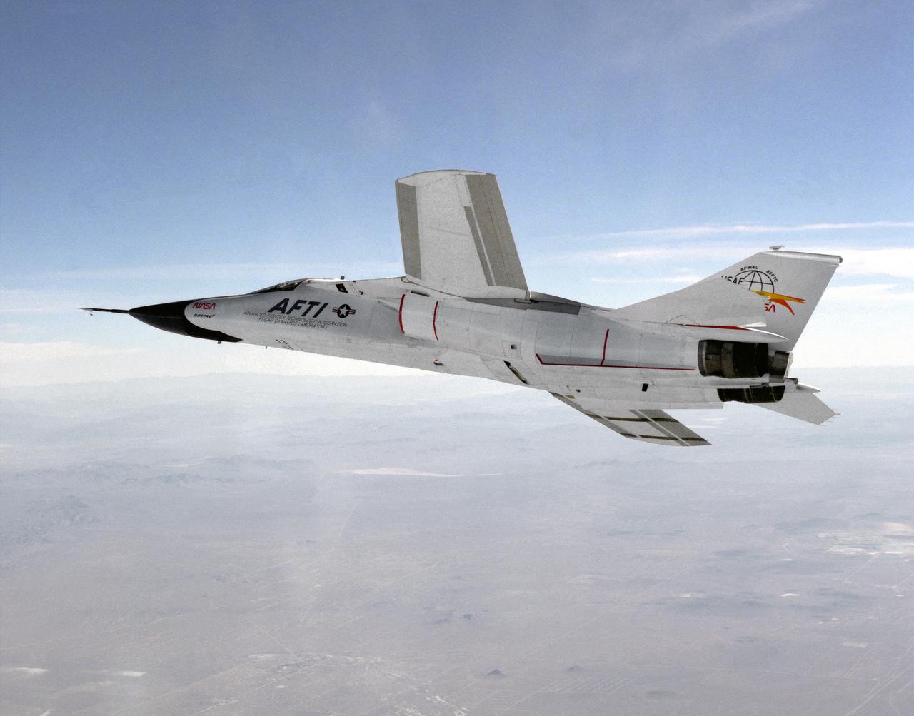
This photograph shows a modified General Dynamics AFTI/F-111A Aardvark with supercritical mission adaptive wings (MAW) installed. The AFTI/F111A is seen banking towards Rodgers Dry Lake and Edwards Air Force Base. With the phasing out of the TACT program came a renewed effort by the Air Force Flight Dynamics Laboratory to extend supercritical wing technology to a higher level of performance. In the early 1980s the supercritical wing on the F-111A aircraft was replaced with a wing built by Boeing Aircraft Company System called a “mission adaptive wing” (MAW), and a joint NASA and Air Force program called Advanced Fighter Technology Integration (AFTI) was born.
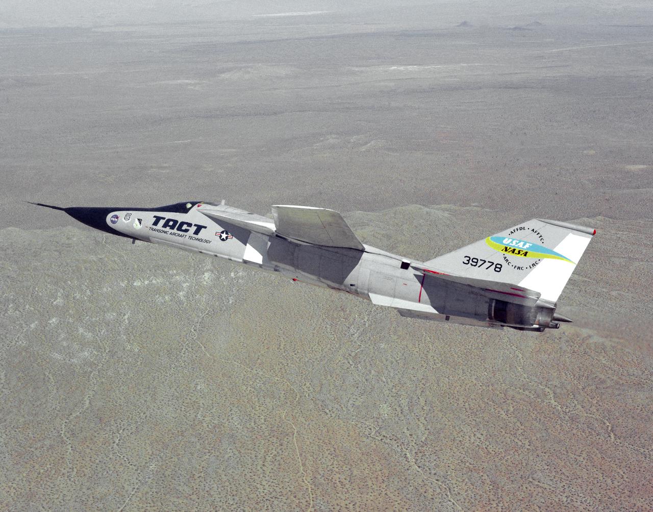
The General Dynamics TACT/F-111A Aardvark is seen In a banking-turn over the California Mojave desert. This photograph affords a good view of the supercritical wing airfoil shape. Starting in 1971 the NASA Flight Research Center and the Air Force undertook a major research and flight testing program, using F-111A (#63-9778), which would span almost 20 years before completion. Intense interest over the results coming from the NASA F-8 supercritical wing program spurred NASA and the Air Force to modify the General Dynamics F-111A to explore the application of supercritical wing technology to maneuverable military aircraft. This flight program was called Transonic Aircraft Technology (TACT).
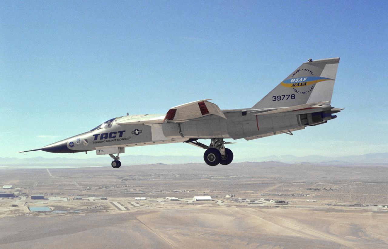
This photograph shows a modified General Dynamics TACT/F-111A Aardvaark with supercritical wings installed. The aircraft, with flaps and landing gear down, is in a decending turn over Rogers Dry Lakebed at Edwards Air Force Base. Starting in 1971 the NASA Flight Research Center and the Air Force undertook a major research and flight testing program, using F-111A (#63-9778), which would span almost 20 years before completion. Intense interest over the results coming from the NASA F-8 supercritical wing program spurred NASA and the Air Force to modify the General Dynamics-Convair F-111A to explore the application of supercritical wing technology to maneuverable military aircraft. This flight program was called Transonic Aircraft Technology (TACT).