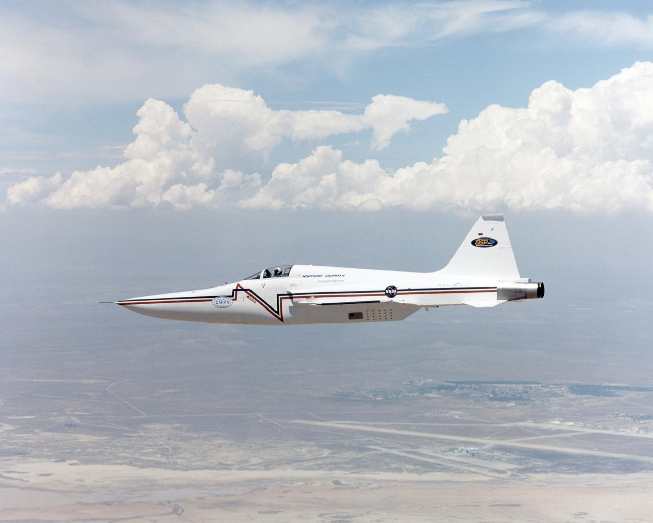
Northrop-Grumman Corporation's modified U.S. Navy F-5E Shaped Sonic Boom Demonstration (SSBD) aircraft.
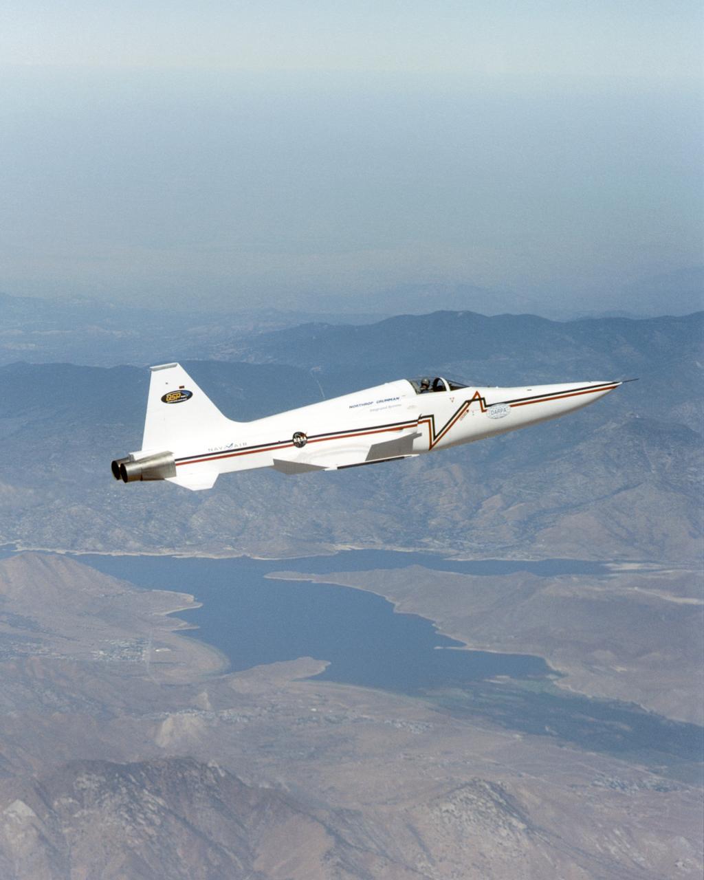
Northrop Grumman Corporation's modified U.S. Navy F-5E Shaped Sonic Boom Demonstration (SSBD) aircraft flies over Lake Isabella, California on Aug. 4, 2003. NASA Dryden provided range, air and ground data-gathering support for the SSBD project, which is part of DARPA's Quiet Supersonic Platform (QSP) program.
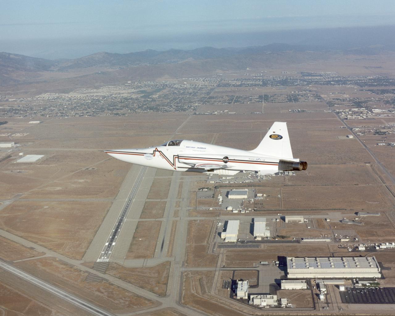
Northrop Grumman Corporation's modified U.S. Navy F-5E Shaped Sonic Boom Demonstration (SSBD) aircraft flies over the company's Palmdale, California facilities on Aug. 2, 2003. NASA Dryden provided range, air and ground data-gathering support for the SSBD project, which is part of DARPA's Quiet Supersonic Platform (QSP) program.
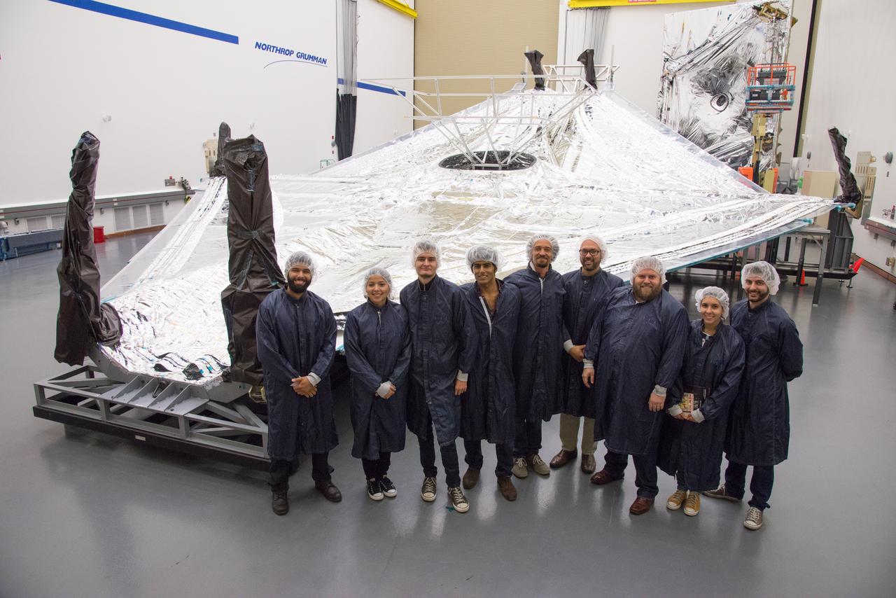
Students and teachers from the New York Film Academy visited Northrop Grumman’s Space Park facility in December 2014 for a tour of the James Webb Space Telescope, and got an up-close look at the tennis-court-sized sunshield that will keep the telescope cool in deep space. Photo courtesy of Northrop Grumman Corporation

This image shows a plastic 1/48-scale model of an F-18 aircraft inside the "Water Tunnel" more formally known as the NASA Dryden Flow Visualization Facility. Water is pumped through the tunnel in the direction of normal airflow over the aircraft; then, colored dyes are pumped through tubes with needle valves. The dyes flow back along the airframe and over the airfoils highlighting their aerodynamic characteristics. The aircraft can also be moved through its pitch axis to observe airflow disruptions while simulating actual flight at high angles of attack. The Water Tunnel at NASA's Dryden Flight Research Center, Edwards, CA, became operational in 1983 when Dryden was a Flight Research Facility under the management of the Ames Research Center in Mountain View, CA. As a medium for visualizing fluid flow, water has played a significant role. Its use dates back to Leonardo da Vinci (1452-1519), the Renaissance Italian engineer, architect, painter, and sculptor. In more recent times, water tunnels have assisted the study of complex flows and flow-field interactions on aircraft shapes that generate strong vortex flows. Flow visualization in water tunnels assists in determining the strength of vortices, their location, and possible methods of controlling them. The design of the Dryden Water Tunnel imitated that of the Northrop Corporation's tunnel in Hawthorne, CA. Called the Flow Visualization Facility, the Dryden tunnel was built to assist researchers in understanding the aerodynamics of aircraft configured in such a way that they create strong vortex flows, particularly at high angles of attack. The tunnel provides results that compare well with data from aircraft in actual flight in another fluid-air. Other uses of the tunnel have included study of how such flight hardware as antennas, probes, pylons, parachutes, and experimental fixtures affect airflow. The facility has also been helpful in finding the best locations for emitting smoke from flight vehicles for flow vi
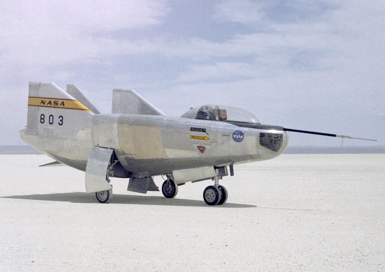
The M2-F3 Lifting Body is seen here on the lakebed next to the NASA Flight Research Center (FRC--later Dryden Flight Research Center), Edwards, California. The May 1967 crash of the M2-F2 had torn off the left fin and landing gear. It had also damaged the external skin and internal structure. Flight Research Center engineers worked with Ames Research Center and the Air Force in redesigning the vehicle with a center fin to provide greater stability. Then Northrop Corporation cooperated with the FRC in rebuilding the vehicle. The entire process took three years.
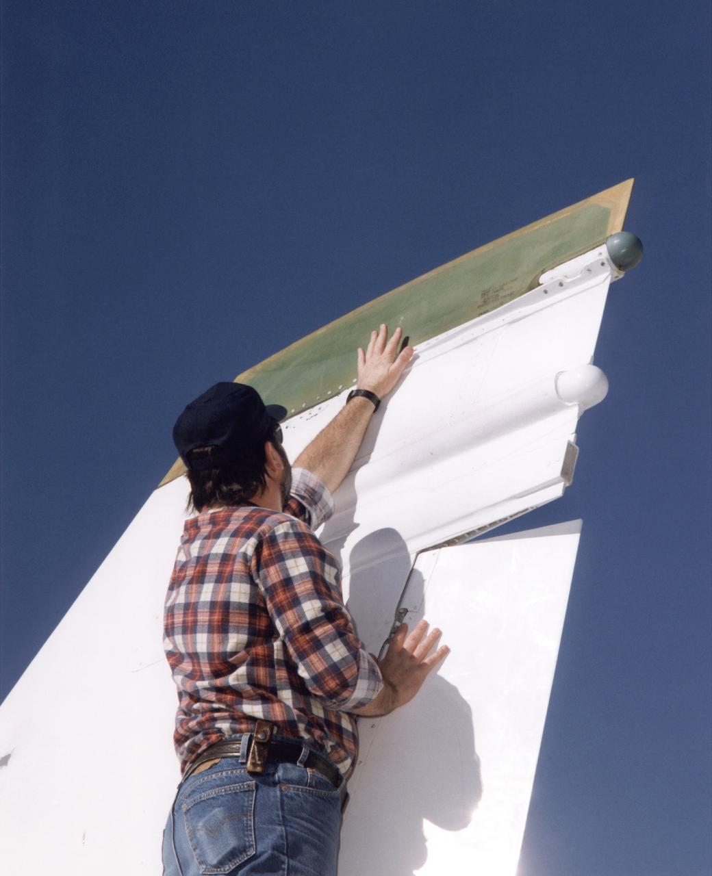
Bob Cummings, a technician at NASA's Dryden Flight Research Center, Edwards, California, checks out a new "Smart Skin" antenna mounted on the tip of the right vertical fin of Dryden's F/A-18 Systems Research Aircraft. Flight tests of the antenna system demonstrated a five-fold increase in voice communications range and a substantial improvement in the pattern of radiation and quality of transmission compared to the standard dorsal blade antenna on the aircraft. The Smart Skin antenna system was electrically as well as physically connected to the airframe, making the aircraft skin operate as an antenna along with the antenna itself. The concept was developed by TRW Avionics Systems Division and integrated into the F/A-18's vertical fin by Northrop-Grumman Corporation.
NASA's Marshall Space Flight Center in Huntsville, Alabama, manages the Space Launch Initiative (SLI), NASA's priority developmental program focused on empowering America's leadership in space. SLI includes commercial, higher education, and defense partnerships and contracts to offer widespread participation in both the risk and success of developing our nation's next-generation reusable launch vehicle. This photo depicts an artist's concept of a future second-generation launch vehicle. For the SLI, architecture definition includes all components of the next-generation reusable launch system: Earth-to-orbit vehicles (the Space Shuttle is the first generation earth-to-orbit vehicle), crew transfer vehicles, transfer stages, ground processing systems, flight operations systems, and development of business case strategies. Three contractor teams have each been funded to develop potential second- generation reusable launch system architectures: The Boeing Company of Seal Beach, California; Lockheed Martin Corporation of Denver, Colorado along with a team including Northrop Grumman of El Segundo, California; and Orbital Sciences Corporation of Dulles, Virginia.
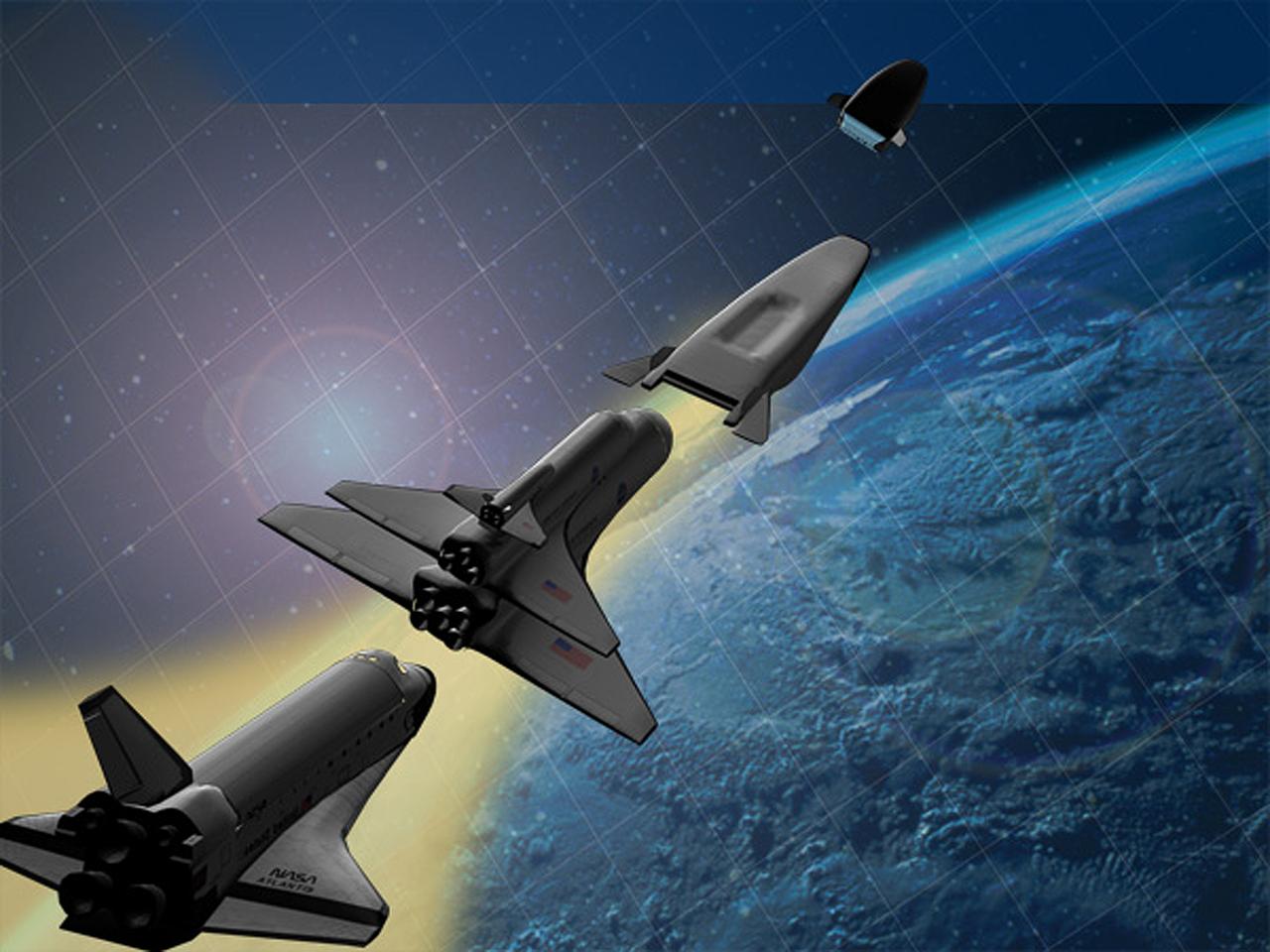
NASA's Marshall Space Flight Center in Huntsville, Alabama, manages the Space Launch Initiative (SLI), NASA's priority developmental program focused on empowering America's leadership in space. SLI includes commercial, higher education and defense partnerships and contracts to offer widespread participation in both the risk and success of developing our nation's next-generation reusable launch vehicle. This photo depicts an artist's concept of a future second-generation launch vehicle during separation of stages. For SLI, architecture definition includes all components of the next-generation reusable launch system: Earth-to-orbit vehicles (the Space Shuttle is the first-generation earth-to-orbit vehicle), crew transfer vehicles, transfer stages, ground processing systems, flight operations systems, and development of business case strategies. Three contractor teams have each been funded to develop potential second generation reusable launch system architectures: The Boeing Company of Seal Beach, California; Lockheed Martin Corporation of Denver, Colorado; a team including Northrop Grumman of El Segundo, California; and Orbital Sciences Corporation of Dulles, Virginia.
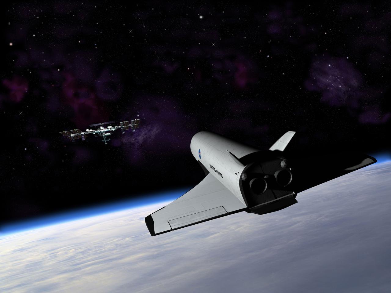
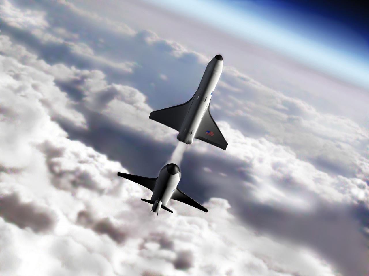
NASA's Marshall Space Flight Center in Huntsville, Alabama, manages the Space Launch Initiative (SLI), NASA's priority developmental program focused on empowering America's leadership in space. SLI includes commercial, higher education, and Defense partnerships and contracts to offer widespread participation in both the risk and success of developing our nation's next-generation reusable launch vehicle. This photo depicts an artist's concept of a future second-generation launch vehicle enroute to the International Space Station. For the SLI, architecture definition includes all components of the next-generation reusable launch system: Earth-to-orbit vehicles (the Space Shuttle is the first generation earth-to-orbit vehicle), crew transfer vehicles, transfer stages, ground processing systems, flight operations systems, and development of business case strategies. Three contractor teams have each been funded to develop potential second-generation reusable launch system architectures: The Boeing Company of Seal Beach, California; Lockheed Martin Corporation of Denver, Colorado along with a team including Northrop Grumman of El Segundo, California; and Orbital Sciences Corporation of Dulles, Virginia.
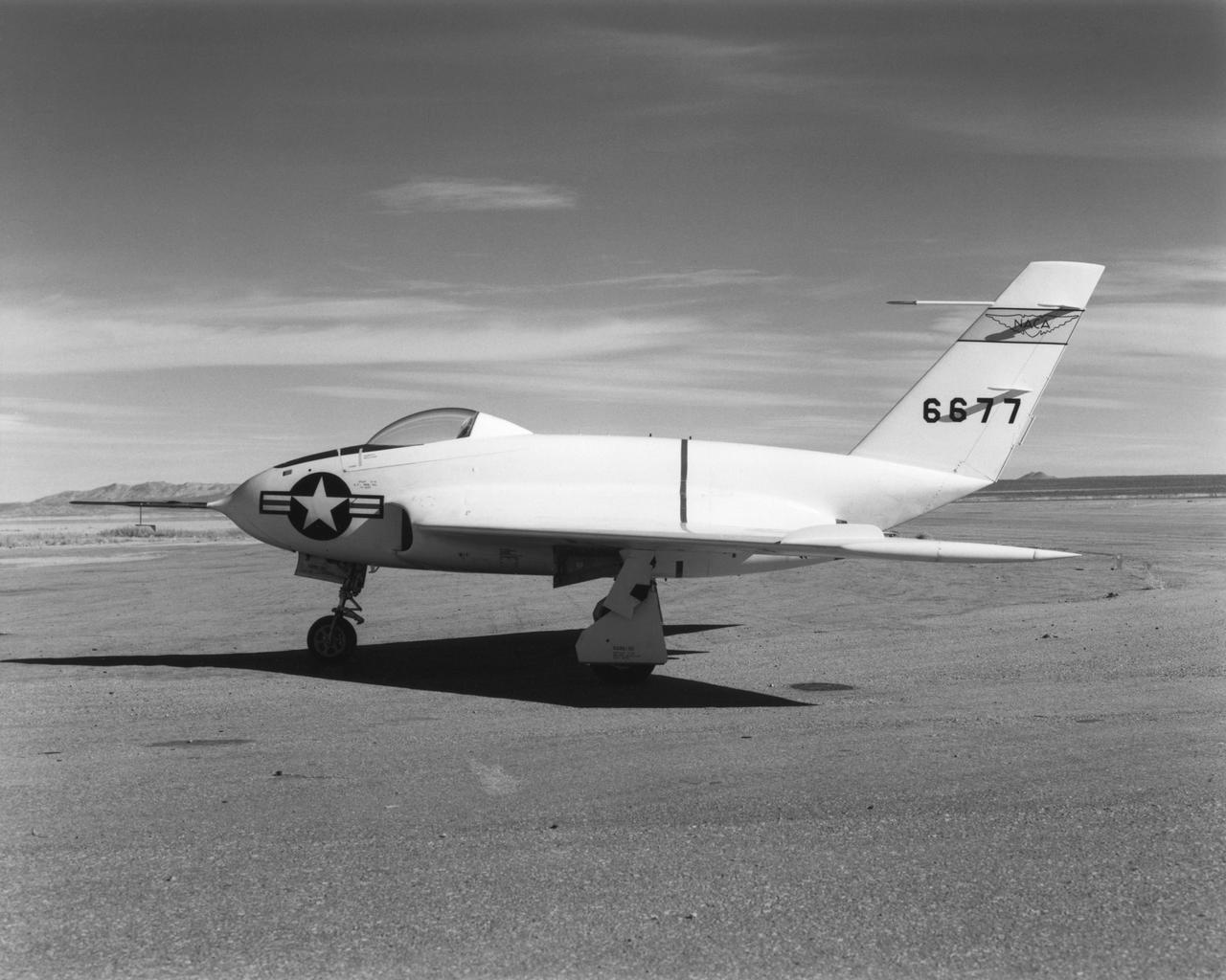
In this 1950 view of the left side of the NACA High-Speed Flight Research Station's X-4 research aircraft, the low swept wing and horizontal taillest design are seen. The X-4 Bantam, a single-place, low swept-wing, semi-tailless aircraft, was designed and built by Northrop Aircraft, Inc. It had no horizontal tail surfaces and its mission was to obtain in-flight data on the stability and control of semi-tailless aircraft at high subsonic speeds.

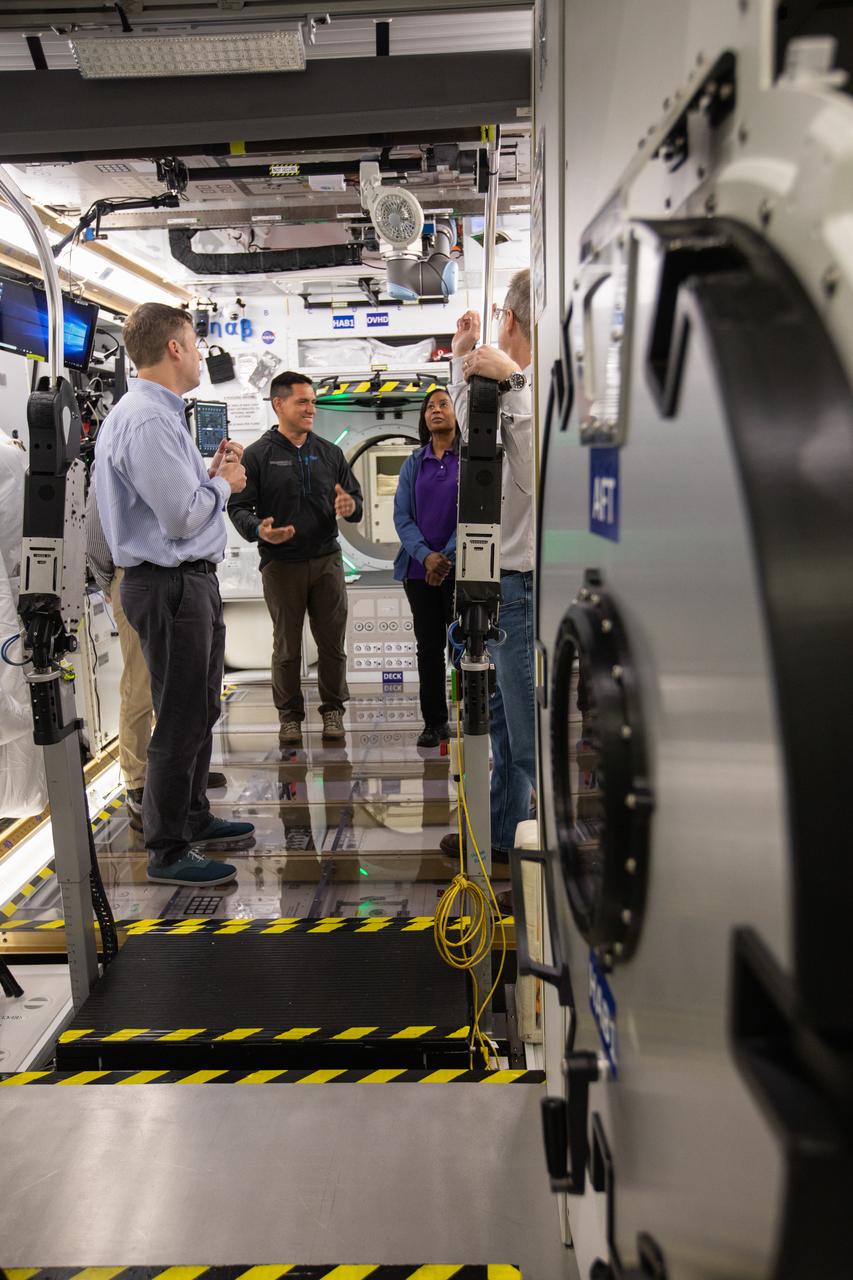
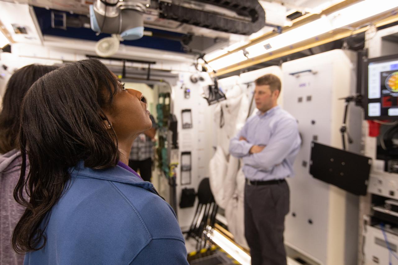
NASA astronaut Raja Chari climbs through a hatch of Lockheed Martin’s deep space habitat ground prototype at NASA’s Kennedy Space Center in Florida on March 25, 2019. Chari is one of the astronauts helping engineers refine requirements for the design of an American-made deep space habitat for the Gateway. Astronauts provide important design perspective as they may one day live and work aboard the lunar outpost, which would be located about 250,000 miles from Earth. To date, five habitat prototypes have been developed through NASA’s Next Space Exploration for Technologies Partnerships, or NextSTEP. Lockheed Martin was the first to turn their habitat over to NASA for testing. Ground prototypes developed by Bigelow Aerospace, Boeing, Northrop Grumman and Sierra Nevada Corporation will be tested in the future at various facilities across the country. A sixth company, NanoRacks, plans to develop a prototype as well.
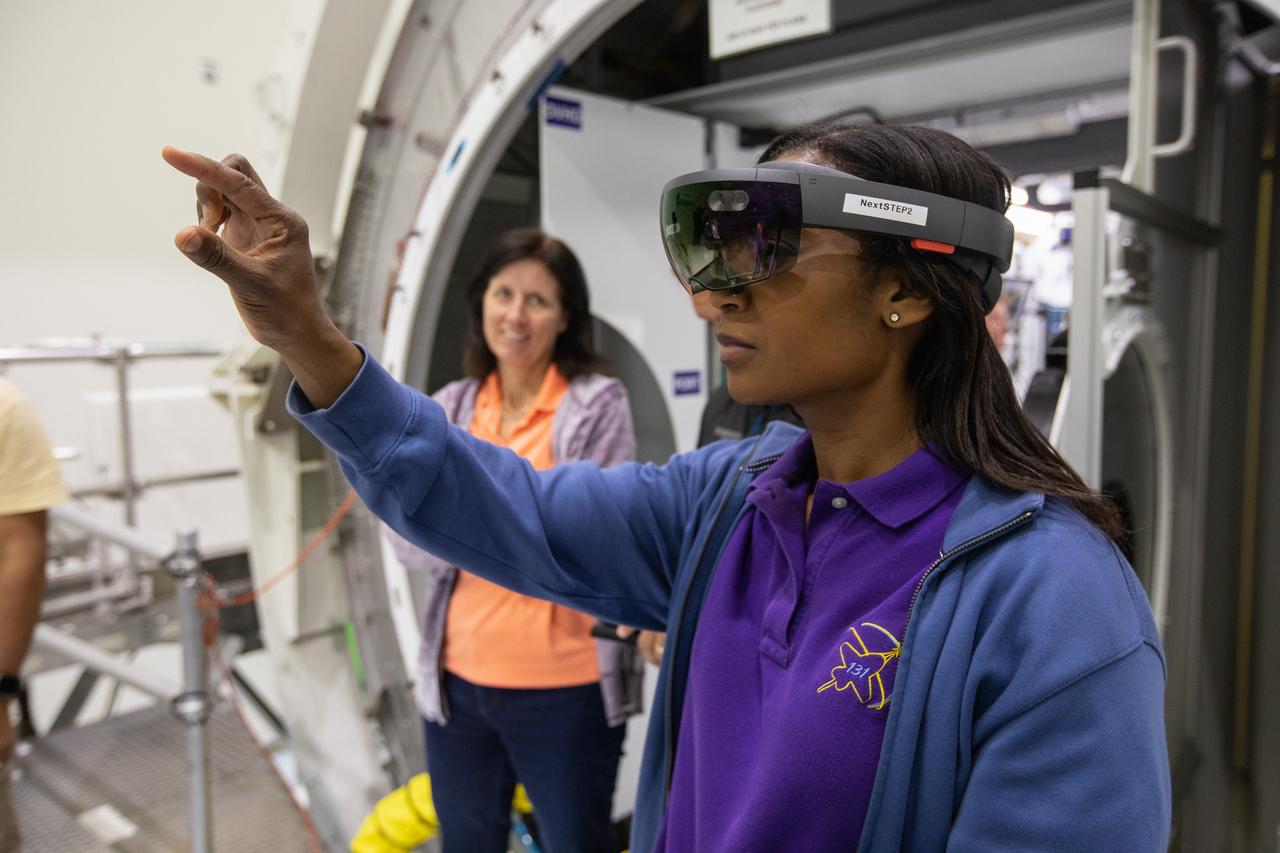
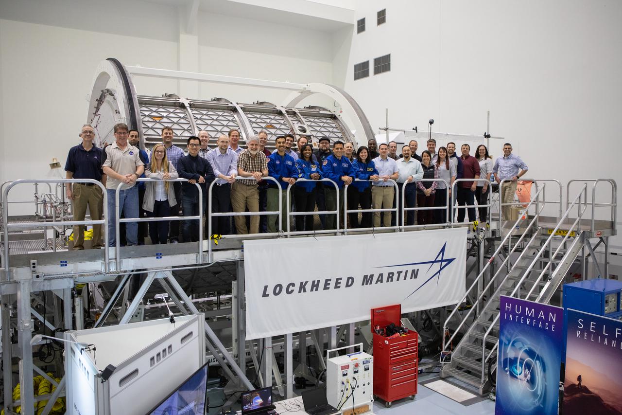
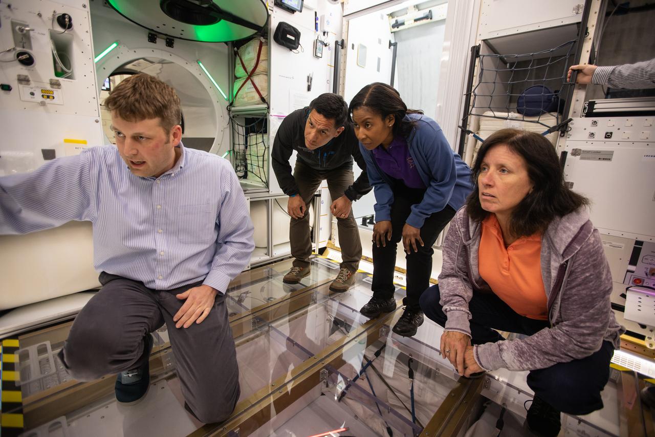
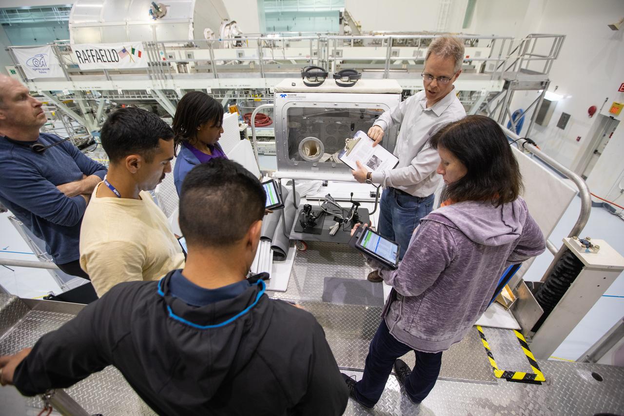
NASA began evaluating five habitat prototypes developed through NASA’s Next Space Exploration for Technologies Partnerships, or NextSTEP, to help engineers refine requirements for the design of an American-made deep space habitat for the Gateway. Lockheed Martin turned over its prototype to NASA, and testing began with crew on March 25, 2019, at Kennedy Space Center in Florida. Pictured inside the Space Station Processing Facility on March 26, 2019, from left are astronauts Shannon Walker and Stephanie Wilson. Astronauts are participating in the evaluations to provide their perspectives as those who may one day live aboard the lunar outpost, which would be located about 250,000 miles from Earth. Ground prototypes developed by Bigelow Aerospace, Boeing, Northrop Grumman, and Sierra Nevada Corporation will be tested in the future at various facilities across the country. A sixth company, NanoRacks, plans to develop a prototype as well.
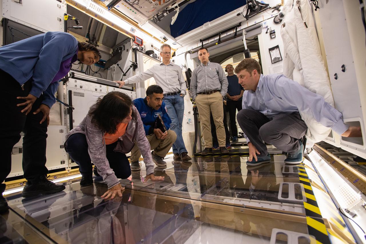
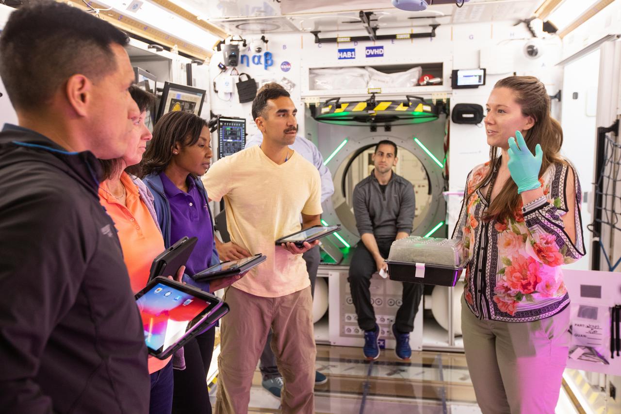
NASA began evaluating five habitat prototypes developed through NASA’s Next Space Exploration for Technologies Partnerships, or NextSTEP, to help engineers refine requirements for the design of an American-made deep space habitat for the Gateway. Lockheed Martin turned over its prototype to NASA, and testing began with crew on March 25, 2019, at Kennedy Space Center in Florida. Pictured inside the habitat prototype on March 26, 2019, from left are astronauts Stephanie Wilson, Shannon Walker and Raja Chari. Astronauts are participating in the evaluations to provide their perspectives as those who may one day live aboard the lunar outpost, which would be located about 250,000 miles from Earth. Ground prototypes developed by Bigelow Aerospace, Boeing, Northrop Grumman, and Sierra Nevada Corporation will be tested in the future at various facilities across the country. A sixth company, NanoRacks, plans to develop a prototype as well.
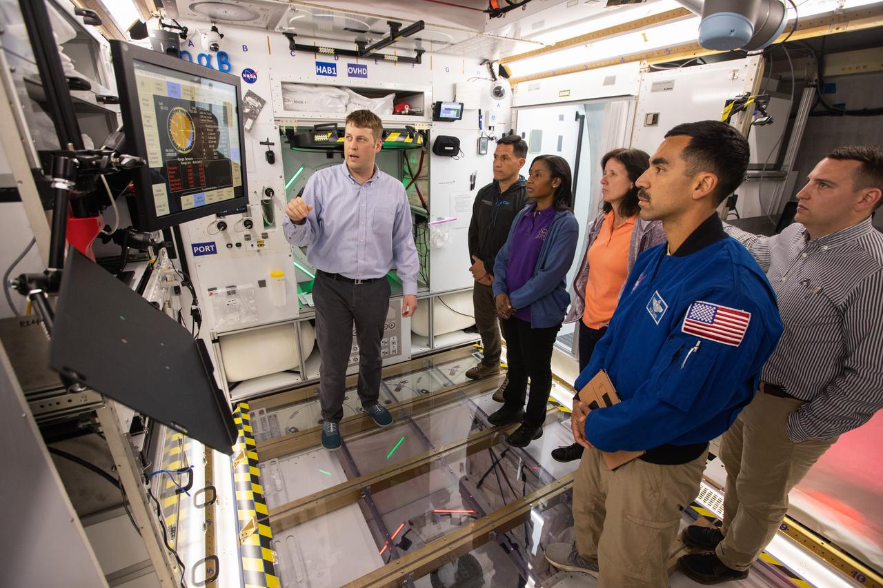
NASA began evaluating five habitat prototypes developed through NASA’s Next Space Exploration for Technologies Partnerships, or NextSTEP, to help engineers refine requirements for the design of an American-made deep space habitat for the Gateway. Lockheed Martin turned over its prototype to NASA, and testing began with crew on March 25, 2019, at Kennedy Space Center in Florida. Pictured inside the habitat prototype on March 26, 2019, second from left is astronaut Frank Rubio. Next to him is astronaut Stephanie Wilson. Astronauts are participating in the evaluations to provide their perspectives as those who may one day live aboard the lunar outpost, which would be located about 250,000 miles from Earth. Ground prototypes developed by Bigelow Aerospace, Boeing, Northrop Grumman, and Sierra Nevada Corporation will be tested in the future at various facilities across the country. A sixth company, NanoRacks, plans to develop a prototype as well.
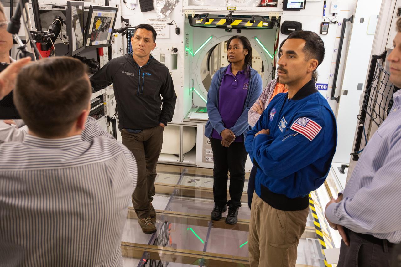
NASA began evaluating five habitat prototypes developed through NASA’s Next Space Exploration for Technologies Partnerships, or NextSTEP, to help engineers refine requirements for the design of an American-made deep space habitat for the Gateway. Lockheed Martin turned over its prototype to NASA, and testing began with crew on March 25, 2019, at Kennedy Space Center in Florida. Pictured inside the habitat prototype on March 26, 2019, from left are astronauts Frank Rubio, Stephanie Wilson and Raja Chari. Partially in view next to Chari is astronaut Shannon Walker. Astronauts are participating in the evaluations to provide their perspectives as those who may one day live aboard the lunar outpost, which would be located about 250,000 miles from Earth. Ground prototypes developed by Bigelow Aerospace, Boeing, Northrop Grumman, and Sierra Nevada Corporation will be tested in the future at various facilities across the country. A sixth company, NanoRacks, plans to develop a prototype as well.
NASA began evaluating five habitat prototypes developed through NASA’s Next Space Exploration for Technologies Partnerships, or NextSTEP, to help engineers refine requirements for the design of an American-made deep space habitat for the Gateway. Lockheed Martin turned over its prototype to NASA, and testing began with crew on March 25, 2019, at Kennedy Space Center in Florida. Pictured inside the habitat prototype on March 26, 2019, from far left are astronauts Frank Rubio, Shannon Walker, Stephanie Wilson and Raja Chari. Astronauts are participating in the evaluations to provide their perspectives as those who may one day live aboard the lunar outpost, which would be located about 250,000 miles from Earth. Ground prototypes developed by Bigelow Aerospace, Boeing, Northrop Grumman, and Sierra Nevada Corporation will be tested in the future at various facilities across the country. A sixth company, NanoRacks, plans to develop a prototype as well.
NASA began evaluating five habitat prototypes developed through NASA’s Next Space Exploration for Technologies Partnerships, or NextSTEP, to help engineers refine requirements for the design of an American-made deep space habitat for the Gateway. Lockheed Martin turned over its prototype to NASA, and testing began with crew on March 25, 2019, at Kennedy Space Center in Florida. Astronauts are participating in the evaluations to provide their perspectives as those who may one day live aboard the lunar outpost, which would be located about 250,000 miles from Earth. Ground prototypes developed by Bigelow Aerospace, Boeing, Northrop Grumman, and Sierra Nevada Corporation will be tested in the future at various facilities across the country. A sixth company, NanoRacks, plans to develop a prototype as well.
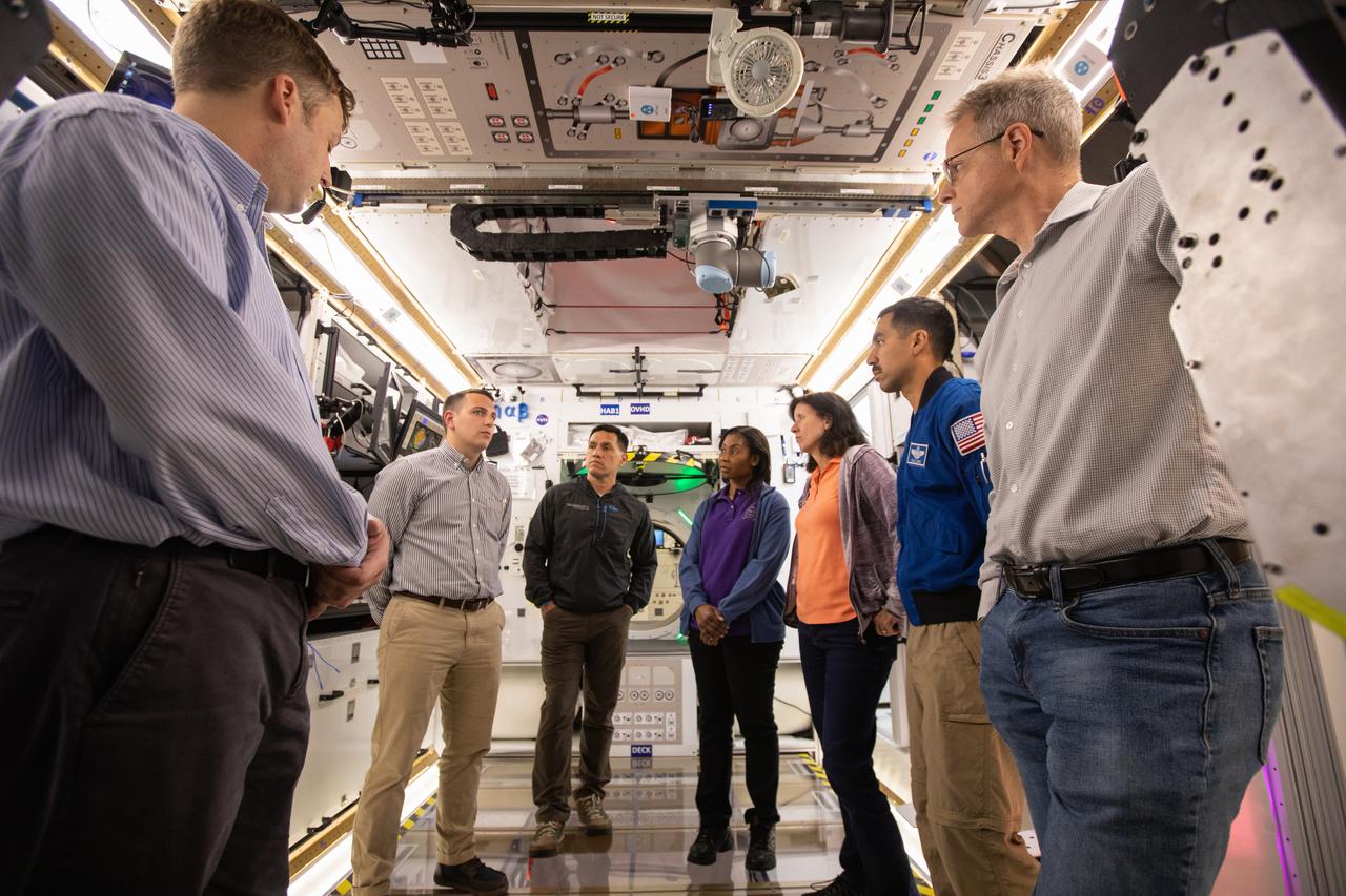
NASA began evaluating five habitat prototypes developed through NASA’s Next Space Exploration for Technologies Partnerships, or NextSTEP, to help engineers refine requirements for the design of an American-made deep space habitat for the Gateway. Lockheed Martin turned over its prototype to NASA, and testing began with crew on March 25, 2019, at Kennedy Space Center in Florida. Pictured inside the habitat prototype on March 26, 2019, in back from left are astronauts Frank Rubio, Stephanie Wilson and Shannon Walker. Astronauts are participating in the evaluations to provide their perspectives as those who may one day live aboard the lunar outpost, which would be located about 250,000 miles from Earth. Ground prototypes developed by Bigelow Aerospace, Boeing, Northrop Grumman, and Sierra Nevada Corporation will be tested in the future at various facilities across the country. A sixth company, NanoRacks, plans to develop a prototype as well.
NASA began evaluating five habitat prototypes developed through NASA’s Next Space Exploration for Technologies Partnerships, or NextSTEP, to help engineers refine requirements for the design of an American-made deep space habitat for the Gateway. Lockheed Martin turned over its prototype to NASA, and testing began with crew on March 25, 2019, at Kennedy Space Center in Florida. Pictured inside the habitat prototype on March 26, 2019, beginning second from left are astronauts Frank Rubio, Raja Shari, Stephanie Wilson and Shannon Walker. Astronauts are participating in the evaluations to provide their perspectives as those who may one day live aboard the lunar outpost, which would be located about 250,000 miles from Earth. Ground prototypes developed by Bigelow Aerospace, Boeing, Northrop Grumman, and Sierra Nevada Corporation will be tested in the future at various facilities across the country. A sixth company, NanoRacks, plans to develop a prototype as well.
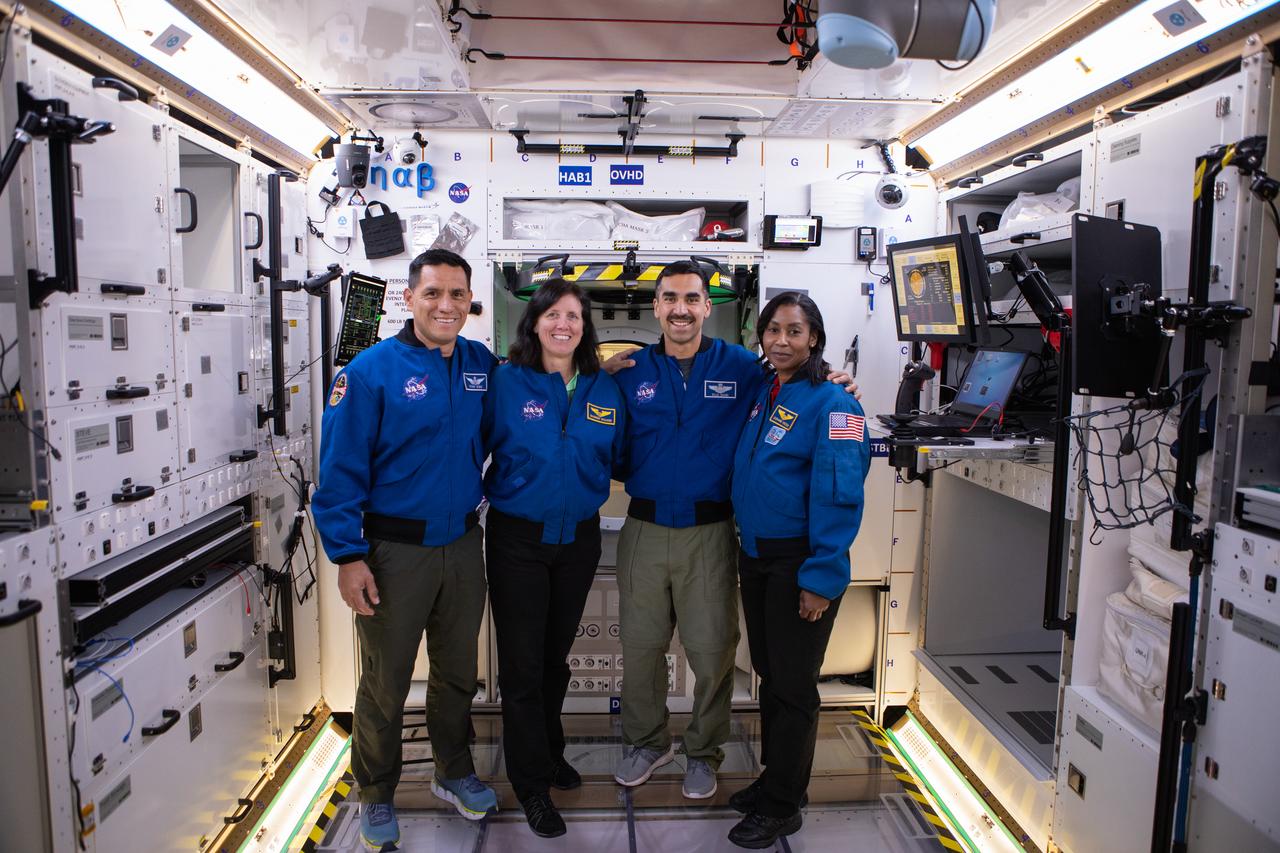
NASA began evaluating five habitat prototypes developed through NASA’s Next Space Exploration for Technologies Partnerships, or NextSTEP, to help engineers refine requirements for the design of an American-made deep space habitat for the Gateway. Lockheed Martin turned over its prototype to NASA, and testing began with crew on March 25, 2019, at Kennedy Space Center in Florida. Pictured, from left are astronauts Frank Rubio, Shannon Walker, Raja Chari and Stephanie Wilson. Astronauts are participating in the evaluations to provide their perspectives as those who may one day live aboard the lunar outpost, which would be located about 250,000 miles from Earth. Ground prototypes developed by Bigelow Aerospace, Boeing, Northrop Grumman, and Sierra Nevada Corporation will be tested in the future at various facilities across the country. A sixth company, NanoRacks, plans to develop a prototype as well.
NASA began evaluating five habitat prototypes developed through NASA’s Next Space Exploration for Technologies Partnerships, or NextSTEP, to help engineers refine requirements for the design of an American-made deep space habitat for the Gateway. Lockheed Martin turned over its prototype to NASA, and testing began with crew on March 25, 2019, at Kennedy Space Center in Florida. Pictured inside the habitat prototype on March 26, 2019, beginning third from left are astronauts Frank Rubio, Stephanie Wilson, Shannon Walker and Raja Chari. Astronauts are participating in the evaluations to provide their perspectives as those who may one day live aboard the lunar outpost, which would be located about 250,000 miles from Earth. Ground prototypes developed by Bigelow Aerospace, Boeing, Northrop Grumman, and Sierra Nevada Corporation will be tested in the future at various facilities across the country. A sixth company, NanoRacks, plans to develop a prototype as well.
NASA began evaluating five habitat prototypes developed through NASA’s Next Space Exploration for Technologies Partnerships, or NextSTEP, to help engineers refine requirements for the design of an American-made deep space habitat for the Gateway. Lockheed Martin turned over its prototype to NASA, and testing began with crew on March 25, 2019, at Kennedy Space Center in Florida. Pictured inside the habitat prototype on March 26, 2019, at left is astronaut Stephanie Wilson. To her left, partially hidden is astronaut Shannon Walker. Astronauts are participating in the evaluations to provide their perspectives as those who may one day live aboard the lunar outpost, which would be located about 250,000 miles from Earth. Ground prototypes developed by Bigelow Aerospace, Boeing, Northrop Grumman, and Sierra Nevada Corporation will be tested in the future at various facilities across the country. A sixth company, NanoRacks, plans to develop a prototype as well.
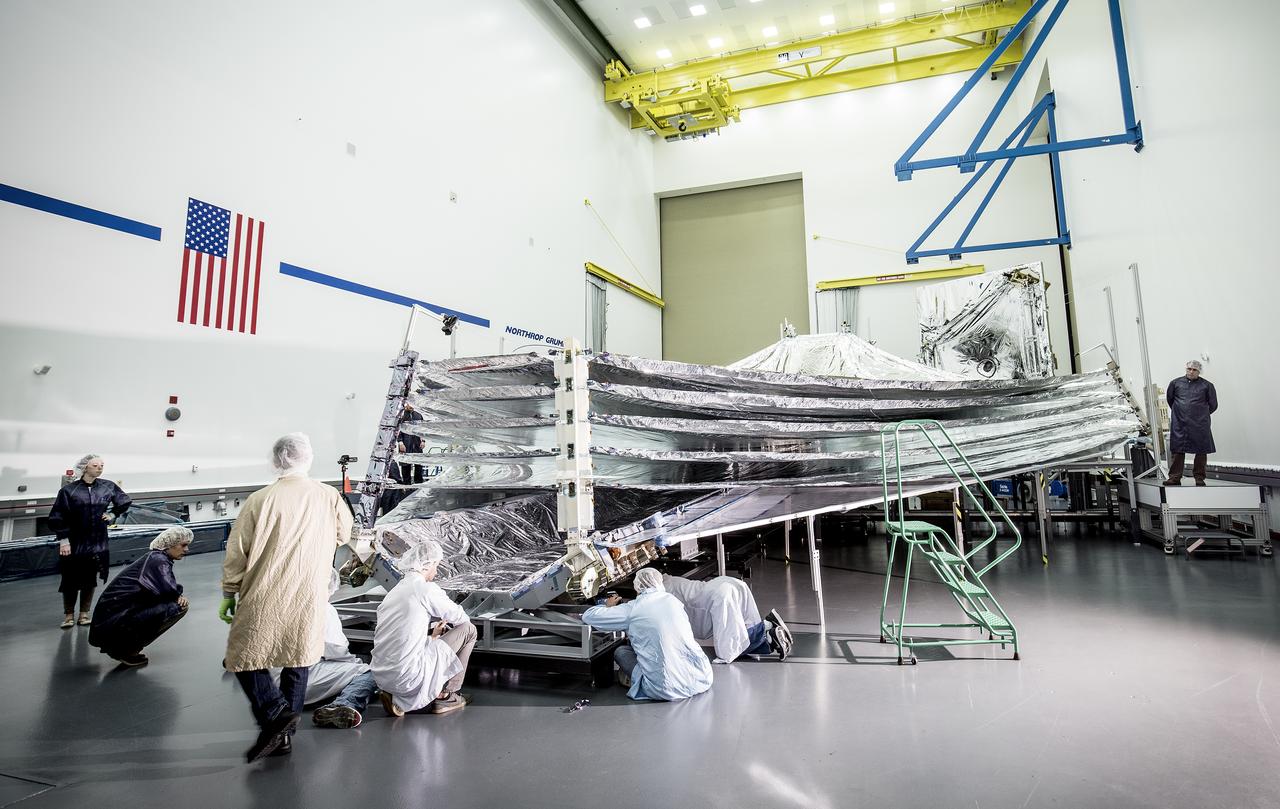
The sunshield on NASA's James Webb Space Telescope is the largest part of the observatory—five layers of thin, silvery membrane that must unfurl reliably in space. The precision in which the tennis-court sized sunshield has to open must be no more than a few centimeters different from its planned position. In this photo, engineers and scientists examine the sunshield layers on this full-sized test unit. Because there's a layer of the shiny silver material on the base under the five layers of the sunshield, it appears as if the sunshield has a mouth that is "open wide" while engineers take a look. The photo was taken in a clean room at Northrop Grumman Corporation, Redondo Beach, California. The sunshield separates the observatory into a warm sun-facing side and a cold side where the sunshine is blocked from interfering with the sensitive infrared instruments. The infrared instruments need to be kept very cold (under 50 K or -370 degrees Fahrenheit) to operate. The sunshield protects these sensitive instruments with an effective sun protection factor, or SPF, of 1,000,000. Sunscreen generally has an SPF of 8 to 50. In addition to providing a cold environment, the sunshield provides a thermally stable environment. This stability is essential to maintaining proper alignment of the primary mirror segments as the telescope changes its orientation to the sun. Earlier this year, the first flight layer of the sunshield was delivered to Northrop Grumman. Northrop Grumman is designing the Webb Telescope’s sunshield for NASA’s Goddard Space Flight Center, in Greenbelt, Maryland. Innovative sunshield membranes are being designed and manufactured by NeXolve Corporation of Huntsville, Alabama. The James Webb Space Telescope is the successor to NASA's Hubble Space Telescope. It will be the most powerful space telescope ever built. Webb is an international project led by NASA with its partners, the European Space Agency and the Canadian Space Agency. For more information about the Webb telescope, visit: <a href="http://www.jwst.nasa.gov" rel="nofollow">www.jwst.nasa.gov</a> or <a href="http://www.nasa.gov/webb" rel="nofollow">www.nasa.gov/webb</a> For more information on the Webb Sunshield, visit: <a href="http://jwst.nasa.gov/sunshield.html" rel="nofollow">jwst.nasa.gov/sunshield.html</a> Photo credit: Alex Evers/Northrop Grumman Corporation <b><a href="http://www.nasa.gov/audience/formedia/features/MP_Photo_Guidelines.html" rel="nofollow">NASA image use policy.</a></b> <b><a href="http://www.nasa.gov/centers/goddard/home/index.html" rel="nofollow">NASA Goddard Space Flight Center</a></b> enables NASA’s mission through four scientific endeavors: Earth Science, Heliophysics, Solar System Exploration, and Astrophysics. Goddard plays a leading role in NASA’s accomplishments by contributing compelling scientific knowledge to advance the Agency’s mission. <b>Follow us on <a href="http://twitter.com/NASAGoddardPix" rel="nofollow">Twitter</a></b> <b>Like us on <a href="http://www.facebook.com/pages/Greenbelt-MD/NASA-Goddard/395013845897?ref=tsd" rel="nofollow">Facebook</a></b> <b>Find us on <a href="http://instagrid.me/nasagoddard/?vm=grid" rel="nofollow">Instagram</a></b>
NASA began evaluating five habitat prototypes developed through NASA’s Next Space Exploration for Technologies Partnerships, or NextSTEP, to help engineers refine requirements for the design of an American-made deep space habitat for the Gateway. Lockheed Martin turned over its prototype to NASA, and testing began with crew on March 25, 2019, at Kennedy Space Center in Florida. Pictured inside the Space Station Processing Facility on March 26, 2019, from far left is astronaut Frank Rubio. In front of him, are Raja Chari and Stephanie Wilson. At right is astronaut Shannon Walker. Astronauts are participating in the evaluations to provide their perspectives as those who may one day live aboard the lunar outpost, which would be located about 250,000 miles from Earth. Ground prototypes developed by Bigelow Aerospace, Boeing, Northrop Grumman, and Sierra Nevada Corporation will be tested in the future at various facilities across the country. A sixth company, NanoRacks, plans to develop a prototype as well.
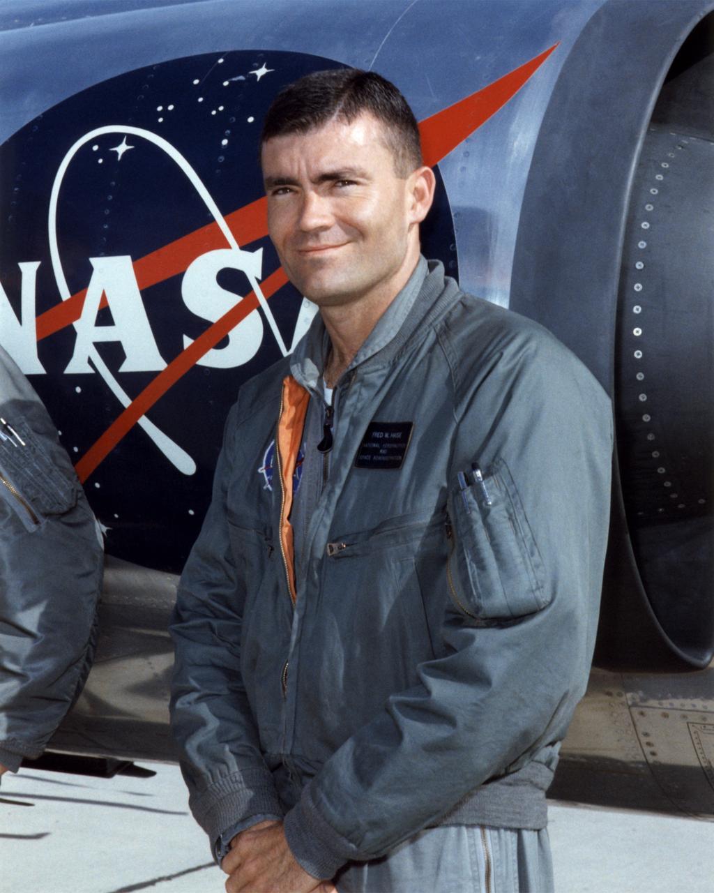
Fred W. Haise Jr. was a research pilot and an astronaut for the National Aeronautics and Space Administration from 1959 to 1979. He began flying at the Lewis Research Center in Cleveland, Ohio (today the Glenn Research Center), in 1959. He became a research pilot at the NASA Flight Research Center (FRC), Edwards, Calif., in 1963, serving NASA in that position for three years until being selected to be an astronaut in 1966 His best-known assignment at the FRC (later redesignated the Dryden Flight Research Center) was as a lifting body pilot. Shortly after flying the M2-F1 on a car tow to about 25 feet on April 22, 1966, he was assigned as an astronaut to the Johnson Space Center in Houston, Texas. While at the FRC he had also flown a variety of other research and support aircraft, including the variable-stability T-33A to simulate the M2-F2 heavyweight lifting body, some light aircraft including the Piper PA-30 to evaluate their handling qualities, the Apache helicopter, the Aero Commander, the Cessna 310, the Douglas F5D, the Lockheed F-104 and T-33, the Cessna T-37, and the Douglas C-47. After becoming an astronaut, Haise served as a backup crewmember for the Apollo 8, 11, and 16 missions. He flew on the aborted Apollo 13 lunar mission in 1970, spending 142 hours and 54 minutes in space before returning safely to Earth. In 1977, he was the commander of three free flights of the Space Shuttle prototype Enterprise when it flew its Approach and Landing Tests at Edwards Air Force Base, Calif. Meanwhile, from April 1973 to January 1976, Haise served as the Technical Assistant to the Manager of the Space Shuttle Orbiter Project. In 1979, he left NASA to become the Vice President for Space Programs with the Grumman Aerospace Corporation. He then served as President of Grumman Technical Services, an operating division of Northrop Grumman Corporation, from January 1992 until his retirement. Haise was born in Biloxi, Miss., on November 14, 1933. He underwent flight traini
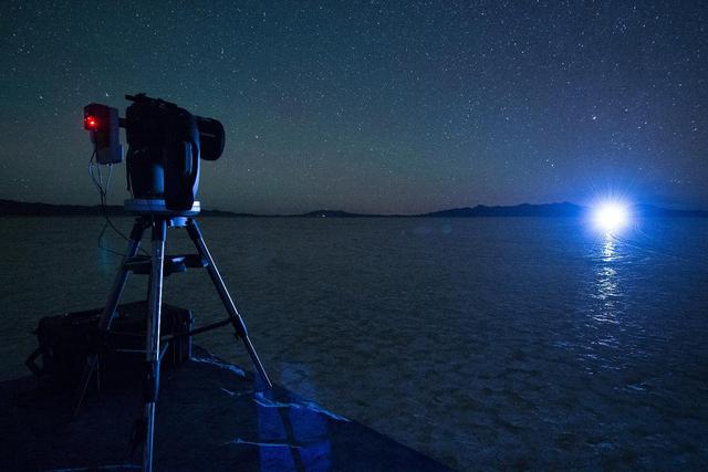
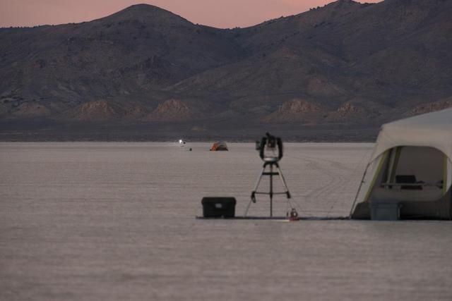
A night test of a small-scale starshade model, in a dry lake bed in central Nevada's Smith Creek by Northrup Grumman, took place in May to June 2014. A telescope points toward a bright light, which in the darkness of the desert mimics the conditions of starlight in space. Other lights, which are up to 10 million times fainter than the light source standing in for the star, represent the reflected light of planets. Telescopes searching for the relatively dim light of an exoplanet next to its much brighter star are faced with a challenge as difficult as searching from Los Angeles for a firefly in New York -- if the firefly is next to the brightness of a lighthouse. The tests by Northrup Grumman determined that a starshade, or external occulter, is capable of blocking starlight to a degree that can indeed reveal the light of a planet. http://photojournal.jpl.nasa.gov/catalog/PIA20901
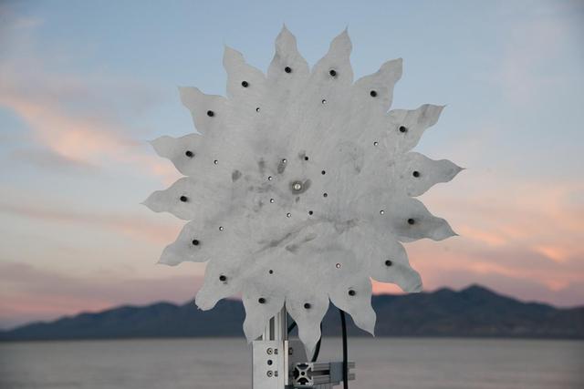
A test of a small-scale starshade model (58 cm), made from metal, in a dry lake bed in central Nevada's Smith Creek, took place from May to June 2014. Nineteen different versions of the miniaturized starshade were tested over five days. The tests revealed that a starshade, or external occulter, is capable of blocking starlight to a degree that reveals the relatively dim reflected light of a planet next to its brighter star. Like holding your hand up to block sunlight, the starshade works to block excessive starlight from the "eyes" of a space telescope like Hubble. http://photojournal.jpl.nasa.gov/catalog/PIA20902
A test of a small-scale starshade model in a dry lake bed in central Nevada's Smith Creek by Northrup Grumman in May-June 2014. A telescope points toward a bright light, which mimics the conditions of starlight in space. Other lights, which are up to 10 million times fainter than the light source standing in for the star, represent the reflected light of planets. Telescopes searching for the relatively dim light of an exoplanet next to its much bright star are faced with a challenge as difficult as searching from Los Angeles for a firefly in New York– if the firefly is also beside a lighthouse. These tests determined that a starshade, or external occulter, is indeed capable of blocking starlight to a degree that reveals the light of a planet. http://photojournal.jpl.nasa.gov/catalog/PIA20908

A view of the one dozen (out of 18) flight mirror segments that make up the primary mirror on NASA's James Webb Space Telescope have been installed at NASA's Goddard Space Flight Center. Credits: NASA/Chris Gunn More: Since December 2015, the team of scientists and engineers have been working tirelessly to install all the primary mirror segments onto the telescope structure in the large clean room at NASA's Goddard Space Flight Center in Greenbelt, Maryland. The twelfth mirror was installed on January 2, 2016. "This milestone signifies that all of the hexagonal shaped mirrors on the fixed central section of the telescope structure are installed and only the 3 mirrors on each wing are left for installation," said Lee Feinberg, NASA's Optical Telescope Element Manager at NASA Goddard. "The incredibly skilled and dedicated team assembling the telescope continues to find ways to do things faster and more efficiently." Each hexagonal-shaped segment measures just over 4.2 feet (1.3 meters) across and weighs approximately 88 pounds (40 kilograms). After being pieced together, the 18 primary mirror segments will work together as one large 21.3-foot (6.5-meter) mirror. The primary mirror will unfold and adjust to shape after launch. The mirrors are made of ultra-lightweight beryllium. The mirrors are placed on the telescope's backplane using a robotic arm, guided by engineers. The full installation is expected to be completed in a few months. The mirrors were built by Ball Aerospace & Technologies Corp., Boulder, Colorado. Ball is the principal subcontractor to Northrop Grumman for the optical technology and lightweight mirror system. The installation of the mirrors onto the telescope structure is performed by Harris Corporation of Rochester, New York. Harris Corporation leads integration and testing for the telescope. While the mirror assembly is a very significant milestone, there are many more steps involved in assembling the Webb telescope. The primary mirror and the tennis-court-sized sunshield are the largest and most visible components of the Webb telescope. However, there are four smaller components that are less visible, yet critical. The instruments that will fly aboard Webb - cameras and spectrographs with detectors able to record extremely faint signals — are part of the Integrated Science Instrument Module (ISIM), which is currently undergoing its final cryogenic vacuum test and will be integrated with the mirror later this year.

Caption: One dozen (out of 18) flight mirror segments that make up the primary mirror on NASA's James Webb Space Telescope have been installed at NASA's Goddard Space Flight Center. Credits: NASA/Chris Gunn More: Since December 2015, the team of scientists and engineers have been working tirelessly to install all the primary mirror segments onto the telescope structure in the large clean room at NASA's Goddard Space Flight Center in Greenbelt, Maryland. The twelfth mirror was installed on January 2, 2016. "This milestone signifies that all of the hexagonal shaped mirrors on the fixed central section of the telescope structure are installed and only the 3 mirrors on each wing are left for installation," said Lee Feinberg, NASA's Optical Telescope Element Manager at NASA Goddard. "The incredibly skilled and dedicated team assembling the telescope continues to find ways to do things faster and more efficiently." Each hexagonal-shaped segment measures just over 4.2 feet (1.3 meters) across and weighs approximately 88 pounds (40 kilograms). After being pieced together, the 18 primary mirror segments will work together as one large 21.3-foot (6.5-meter) mirror. The primary mirror will unfold and adjust to shape after launch. The mirrors are made of ultra-lightweight beryllium. The mirrors are placed on the telescope's backplane using a robotic arm, guided by engineers. The full installation is expected to be completed in a few months. The mirrors were built by Ball Aerospace & Technologies Corp., Boulder, Colorado. Ball is the principal subcontractor to Northrop Grumman for the optical technology and lightweight mirror system. The installation of the mirrors onto the telescope structure is performed by Harris Corporation of Rochester, New York. Harris Corporation leads integration and testing for the telescope. While the mirror assembly is a very significant milestone, there are many more steps involved in assembling the Webb telescope. The primary mirror and the tennis-court-sized sunshield are the largest and most visible components of the Webb telescope. However, there are four smaller components that are less visible, yet critical. The instruments that will fly aboard Webb - cameras and spectrographs with detectors able to record extremely faint signals — are part of the Integrated Science Instrument Module (ISIM), which is currently undergoing its final cryogenic vacuum test and will be integrated with the mirror later this year.
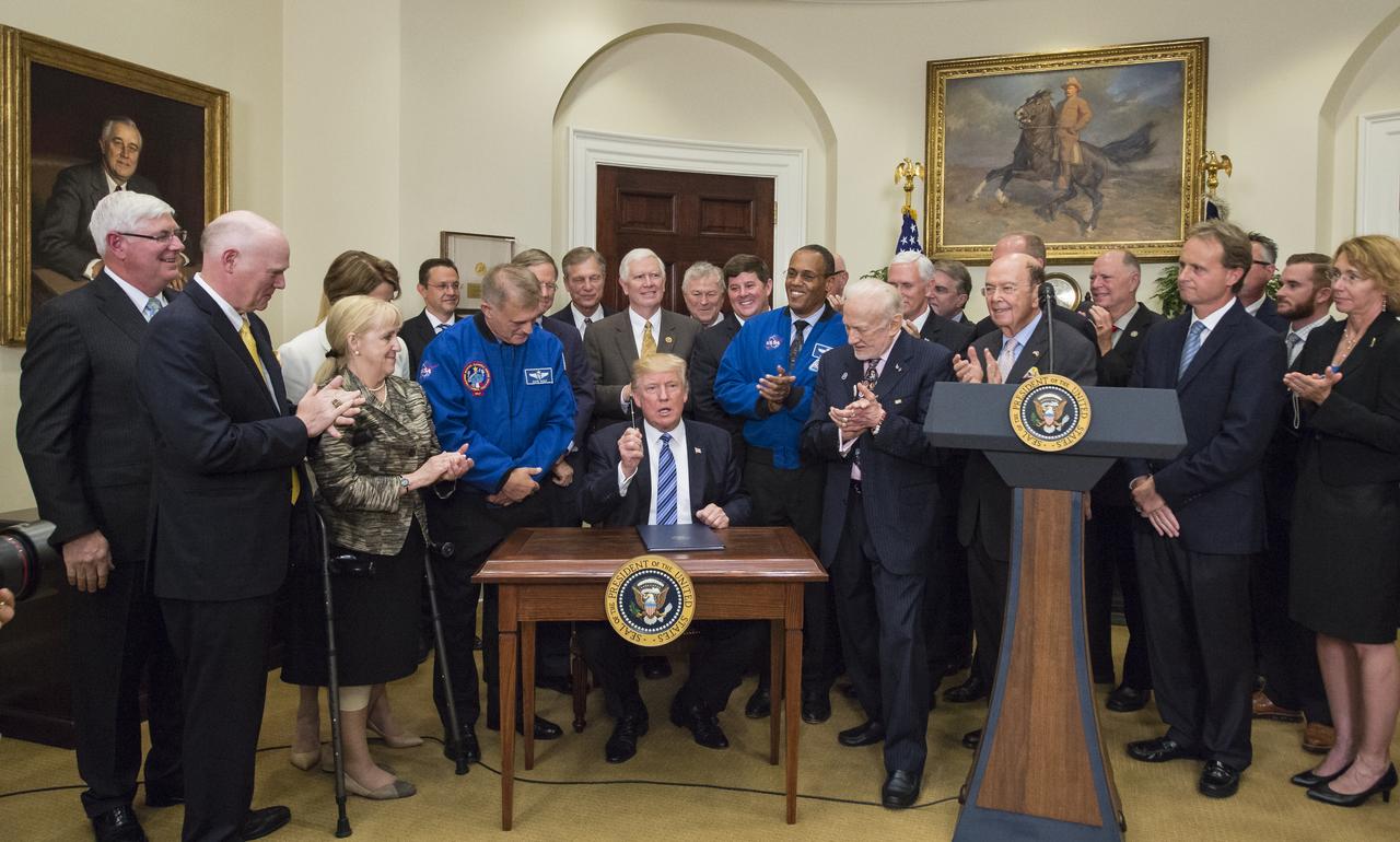
President Donald Trump, center, asks who should receive the pen after signing an Executive Order to reestablish the National Space Council, alongside members of the Congress, National Aeronautics and Space Administration, and Commercial Space Companies in the Roosevelt room of the White House in Washington, Friday, June 30, 2017. Retired astronaut Buzz Aldrin was given the pen. Also pictured are, Vice President Mike Pence, Rep. Bill Posey, R-Florida, Rep. Lamar Smith, R-Texas, Rep. John Culberson, R-Texas, Rep. Steven Palazzo, R-Miss., Rep. Brian Babin, R-Texas, Rep. Mo Brooks, R-Alabama, Rep. Dana Rohrbacher, R-California, Former Rep. Bob Walker, R-Pennsylvania, Sandy Magnus, executive director, American Institute of Aeronautics and Astronautics, David Melcher, executive director, Aerospace Industries Association, Tory Bruno, CEO, United Launch Alliance, Michal Riley, CEO, AMRO Fabricating Corporation, John Couch, president, Futuramic, Mike Cain, owner, Cain Tubular Products, Mary Lynne Dittmar, executive director, Coalition for Deep Space Exploration, Dennis Muilenburg, CEO Boeing Company, Marilyn Hewson, CEO, Lockheed Martin, Wes Bush, CEO, Northrop Grumman, NASA Astronaut Alvin Drew, retired NASA astronaut David Wolf, Apollo 13 flight director, Gene Kranz, Secretary of Commerce Wilbur Ross, Under Secretary of the Air Force Lisa Disbrow, and Acting Deputy Director of National Intelligence, Dawn Eilengerger. Photo Credit: (NASA/Aubrey Gemignani)
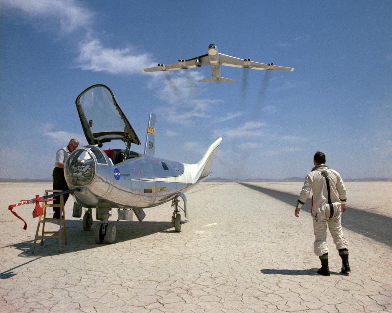
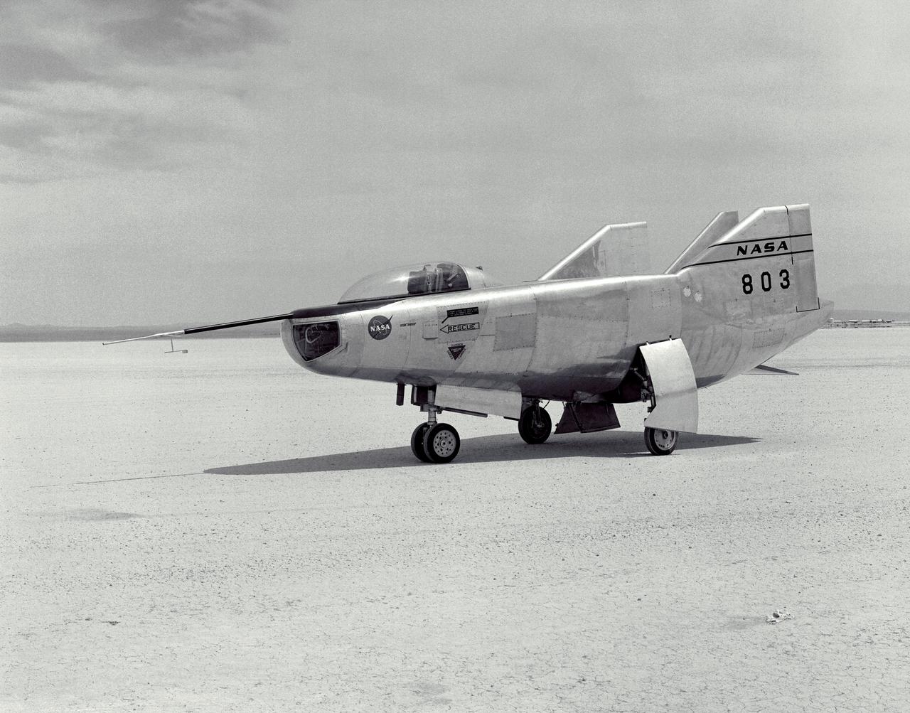
The HL-10 was one of five heavyweight lifting-body designs flown at NASA's Flight Research Center (FRC--later Dryden Flight Research Center), Edwards, California, from July 1966 to November 1975 to study and validate the concept of safely maneuvering and landing a low lift-over-drag vehicle designed for reentry from space. Northrop Corporation built the HL-10 and M2-F2, the first two of the fleet of "heavy" lifting bodies flown by the NASA Flight Research Center. The contract for construction of the HL-10 and the M2-F2 was $1.8 million. "HL" stands for horizontal landing, and "10" refers to the tenth design studied by engineers at NASA's Langley Research Center, Hampton, Va. After delivery to NASA in January 1966, the HL-10 made its first flight on Dec. 22, 1966, with research pilot Bruce Peterson in the cockpit. Although an XLR-11 rocket engine was installed in the vehicle, the first 11 drop flights from the B-52 launch aircraft were powerless glide flights to assess handling qualities, stability, and control. In the end, the HL-10 was judged to be the best handling of the three original heavy-weight lifting bodies (M2-F2/F3, HL-10, X-24A). The HL-10 was flown 37 times during the lifting body research program and logged the highest altitude and fastest speed in the Lifting Body program. On Feb. 18, 1970, Air Force test pilot Peter Hoag piloted the HL-10 to Mach 1.86 (1,228 mph). Nine days later, NASA pilot Bill Dana flew the vehicle to 90,030 feet, which became the highest altitude reached in the program. Some new and different lessons were learned through the successful flight testing of the HL-10. These lessons, when combined with information from it's sister ship, the M2-F2/F3, provided an excellent starting point for designers of future entry vehicles, including the Space Shuttle.
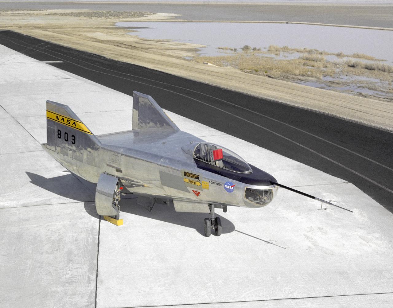
The M2-F2 Lifting Body is seen here on the ramp at the NASA Dryden Flight Research Center. The success of Dryden's M2-F1 program led to NASA's development and construction of two heavyweight lifting bodies based on studies at NASA's Ames and Langley research centers -- the M2-F2 and the HL-10, both built by the Northrop Corporation. The "M" refers to "manned" and "F" refers to "flight" version. "HL" comes from "horizontal landing" and 10 is for the tenth lifting body model to be investigated by Langley. The first flight of the M2-F2 -- which looked much like the "F1" -- was on July 12, 1966. Milt Thompson was the pilot. By then, the same B-52 used to air launch the famed X-15 rocket research aircraft was modified to also carry the lifting bodies. Thompson was dropped from the B-52's wing pylon mount at an altitude of 45,000 feet on that maiden glide flight. The M2-F2 weighed 4,620 pounds, was 22 feet long, and had a width of about 10 feet. On May 10, 1967, during the sixteenth glide flight leading up to powered flight, a landing accident severely damaged the vehicle and seriously injured the NASA pilot, Bruce Peterson. NASA pilots and researchers realized the M2-F2 had lateral control problems, even though it had a stability augmentation control system. When the M2-F2 was rebuilt at Dryden and redesignated the M2-F3, it was modified with an additional third vertical fin -- centered between the tip fins -- to improve control characteristics. The M2-F2/F3 was the first of the heavy-weight, entry-configuration lifting bodies. Its successful development as a research test vehicle answered many of the generic questions about these vehicles. NASA donated the M2-F3 vehicle to the Smithsonian Institute in December 1973. It is currently hanging in the Air and Space Museum along with the X-15 aircraft number 1, which was its hangar partner at Dryden from 1965 to 1969.
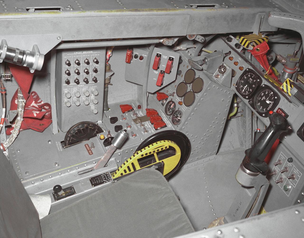
This photo shows the left side cockpit instrumentation panel of the M2-F2 Lifting Body. The success of Dryden's M2-F1 program led to NASA's development and construction of two heavyweight lifting bodies based on studies at NASA's Ames and Langley research centers -- the M2-F2 and the HL-10, both built by the Northrop Corporation. The "M" refers to "manned" and "F" refers to "flight" version. "HL" comes from "horizontal landing" and 10 is for the tenth lifting body model to be investigated by Langley. The first flight of the M2-F2 -- which looked much like the "F1" -- was on July 12, 1966. Milt Thompson was the pilot. By then, the same B-52 used to air launch the famed X-15 rocket research aircraft was modified to also carry the lifting bodies. Thompson was dropped from the B-52's wing pylon mount at an altitude of 45,000 feet on that maiden glide flight. The M2-F2 weighed 4,620 pounds, was 22 feet long, and had a width of about 10 feet. On May 10, 1967, during the sixteenth glide flight leading up to powered flight, a landing accident severely damaged the vehicle and seriously injured the NASA pilot, Bruce Peterson. NASA pilots and researchers realized the M2-F2 had lateral control problems, even though it had a stability augmentation control system. When the M2-F2 was rebuilt at Dryden and redesignated the M2-F3, it was modified with an additional third vertical fin -- centered between the tip fins -- to improve control characteristics. The M2-F2/F3 was the first of the heavy-weight, entry-configuration lifting bodies. Its successful development as a research test vehicle answered many of the generic questions about these vehicles. NASA donated the M2-F3 vehicle to the Smithsonian Institute in December 1973. It is currently hanging in the Air and Space Museum along with the X-15 aircraft number 1, which was its hangar partner at Dryden from 1965 to 1969.
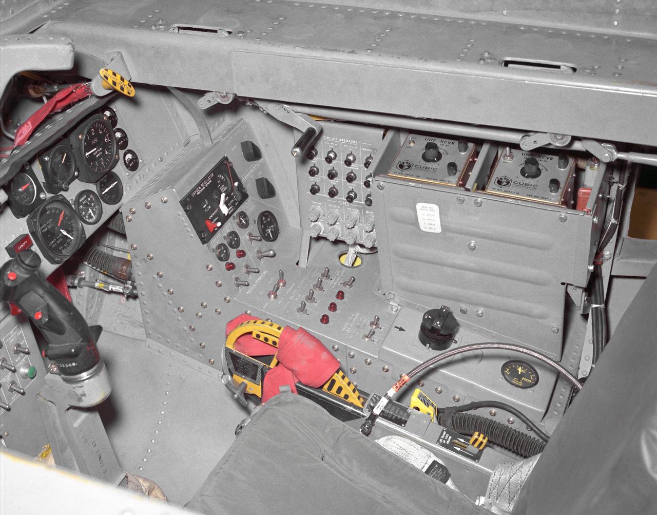
This photo shows the right side cockpit instrumentation panel of the M2-F2 Lifting Body. The success of Dryden's M2-F1 program led to NASA's development and construction of two heavyweight lifting bodies based on studies at NASA's Ames and Langley research centers -- the M2-F2 and the HL-10, both built by the Northrop Corporation. The "M" refers to "manned" and "F" refers to "flight" version. "HL" comes from "horizontal landing" and 10 is for the tenth lifting body model to be investigated by Langley. The first flight of the M2-F2 -- which looked much like the "F1" -- was on July 12, 1966. Milt Thompson was the pilot. By then, the same B-52 used to air launch the famed X-15 rocket research aircraft was modified to also carry the lifting bodies. Thompson was dropped from the B-52's wing pylon mount at an altitude of 45,000 feet on that maiden glide flight. The M2-F2 weighed 4,620 pounds, was 22 feet long, and had a width of about 10 feet. On May 10, 1967, during the sixteenth glide flight leading up to powered flight, a landing accident severely damaged the vehicle and seriously injured the NASA pilot, Bruce Peterson. NASA pilots and researchers realized the M2-F2 had lateral control problems, even though it had a stability augmentation control system. When the M2-F2 was rebuilt at Dryden and redesignated the M2-F3, it was modified with an additional third vertical fin -- centered between the tip fins -- to improve control characteristics. The M2-F2/F3 was the first of the heavy-weight, entry-configuration lifting bodies. Its successful development as a research test vehicle answered many of the generic questions about these vehicles. NASA donated the M2-F3 vehicle to the Smithsonian Institute in December 1973. It is currently hanging in the Air and Space Museum along with the X-15 aircraft number 1, which was its hangar partner at Dryden from 1965 to 1969.
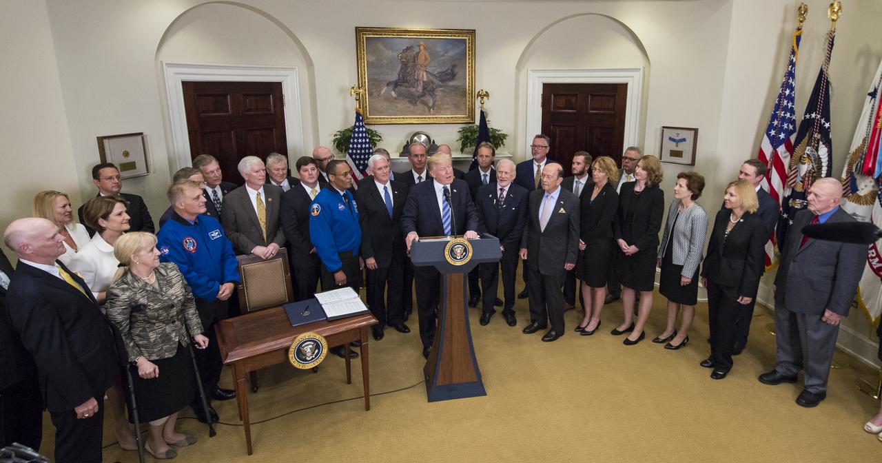
President Donald Trump, center, speaks before signing an Executive Order to reestablish the National Space Council, alongside members of the Congress, National Aeronautics and Space Administration, and Commercial Space Companies in the Roosevelt room of the White House in Washington, Friday, June 30, 2017. Vice President Mike Pence, also in attendance, will chair the council. Also pictured are, Rep. Bill Posey, R-Florida, Rep. Lamar Smith, R-Texas, Rep. John Culberson, R-Texas, Rep. Steven Palazzo, R-Miss., Rep. Brian Babin, R-Texas, Rep. Mo Brooks, R-Alabama, Rep. Dana Rohrbacher, R-California, Former Rep. Bob Walker, R-Pennsylvania, Sandy Magnus, executive director, American Institute of Aeronautics and Astronautics, David Melcher, executive director, Aerospace Industries Association, Tory Bruno, CEO, United Launch Alliance, Michal Riley, CEO, AMRO Fabricating Corporation, John Couch, president, Futuramic, Mike Cain, owner, Cain Tubular Products, Mary Lynne Dittmar, executive director, Coalition for Deep Space Exploration, Dennis Muilenburg, CEO Boeing Company, Marilyn Hewson, CEO, Lockheed Martin, Wes Bush, CEO, Northrop Grumman, retired NASA astronaut Buzz Aldrin, NASA astronaut Alvin Drew, retired NASA astronaut David Wolf, Apollo 13 flight director, Gene Kranz, Secretary of Commerce Wilbur Ross, Under Secretary of the Air Force Lisa Disbrow, and Acting Deputy Director of National Intelligence, Dawn Eilengerger. Photo Credit: (NASA/Aubrey Gemignani)
The M2-F3 Lifting Body is seen here on the lakebed at the NASA Flight Research Center (FRC--later the Dryden Flight Research Center), Edwards, California. After a three-year-long redesign and rebuilding effort, the M2-F3 was ready to fly. The May 1967 crash of the M2-F2 had damaged both the external skin and the internal structure of the lifting body. At first, it seemed that the vehicle had been irreparably damaged, but the original manufacturer, Northrop, did the repair work and returned the redesigned M2-F3 with a center fin for stability to the FRC.
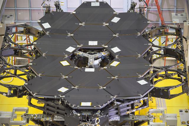
Caption: One dozen (out of 18) flight mirror segments that make up the primary mirror on NASA's James Webb Space Telescope have been installed at NASA's Goddard Space Flight Center. Credits: NASA/Chris Gunn More: Since December 2015, the team of scientists and engineers have been working tirelessly to install all the primary mirror segments onto the telescope structure in the large clean room at NASA's Goddard Space Flight Center in Greenbelt, Maryland. The twelfth mirror was installed on January 2, 2016. "This milestone signifies that all of the hexagonal shaped mirrors on the fixed central section of the telescope structure are installed and only the 3 mirrors on each wing are left for installation," said Lee Feinberg, NASA's Optical Telescope Element Manager at NASA Goddard. "The incredibly skilled and dedicated team assembling the telescope continues to find ways to do things faster and more efficiently." Each hexagonal-shaped segment measures just over 4.2 feet (1.3 meters) across and weighs approximately 88 pounds (40 kilograms). After being pieced together, the 18 primary mirror segments will work together as one large 21.3-foot (6.5-meter) mirror. The primary mirror will unfold and adjust to shape after launch. The mirrors are made of ultra-lightweight beryllium. The mirrors are placed on the telescope's backplane using a robotic arm, guided by engineers. The full installation is expected to be completed in a few months. The mirrors were built by Ball Aerospace & Technologies Corp., Boulder, Colorado. Ball is the principal subcontractor to Northrop Grumman for the optical technology and lightweight mirror system. The installation of the mirrors onto the telescope structure is performed by Harris Corporation of Rochester, New York. Harris Corporation leads integration and testing for the telescope. While the mirror assembly is a very significant milestone, there are many more steps involved in assembling the Webb telescope. The primary mirror and the tennis-court-sized sunshield are the largest and most visible components of the Webb telescope. However, there are four smaller components that are less visible, yet critical. The instruments that will fly aboard Webb - cameras and spectrographs with detectors able to record extremely faint signals — are part of the Integrated Science Instrument Module (ISIM), which is currently undergoing its final cryogenic vacuum test and will be integrated with the mirror later this year. Read more: <a href="http://www.nasa.gov/feature/goddard/2016/by-the-dozen-nasas-james-webb-space-telescope-mirrors" rel="nofollow">www.nasa.gov/feature/goddard/2016/by-the-dozen-nasas-jame...</a> <b><a href="http://www.nasa.gov/audience/formedia/features/MP_Photo_Guidelines.html" rel="nofollow">NASA image use policy.</a></b> <b><a href="http://www.nasa.gov/centers/goddard/home/index.html" rel="nofollow">NASA Goddard Space Flight Center</a></b> enables NASA’s mission through four scientific endeavors: Earth Science, Heliophysics, Solar System Exploration, and Astrophysics. Goddard plays a leading role in NASA’s accomplishments by contributing compelling scientific knowledge to advance the Agency’s mission. <b>Follow us on <a href="http://twitter.com/NASAGoddardPix" rel="nofollow">Twitter</a></b> <b>Like us on <a href="http://www.facebook.com/pages/Greenbelt-MD/NASA-Goddard/395013845897?ref=tsd" rel="nofollow">Facebook</a></b> <b>Find us on <a href="http://instagrid.me/nasagoddard/?vm=grid" rel="nofollow">Instagram</a></b>
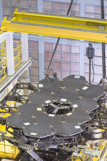
A view of the one dozen (out of 18) flight mirror segments that make up the primary mirror on NASA's James Webb Space Telescope have been installed at NASA's Goddard Space Flight Center. Credits: NASA/Chris Gunn More: Since December 2015, the team of scientists and engineers have been working tirelessly to install all the primary mirror segments onto the telescope structure in the large clean room at NASA's Goddard Space Flight Center in Greenbelt, Maryland. The twelfth mirror was installed on January 2, 2016. "This milestone signifies that all of the hexagonal shaped mirrors on the fixed central section of the telescope structure are installed and only the 3 mirrors on each wing are left for installation," said Lee Feinberg, NASA's Optical Telescope Element Manager at NASA Goddard. "The incredibly skilled and dedicated team assembling the telescope continues to find ways to do things faster and more efficiently." Each hexagonal-shaped segment measures just over 4.2 feet (1.3 meters) across and weighs approximately 88 pounds (40 kilograms). After being pieced together, the 18 primary mirror segments will work together as one large 21.3-foot (6.5-meter) mirror. The primary mirror will unfold and adjust to shape after launch. The mirrors are made of ultra-lightweight beryllium. The mirrors are placed on the telescope's backplane using a robotic arm, guided by engineers. The full installation is expected to be completed in a few months. The mirrors were built by Ball Aerospace & Technologies Corp., Boulder, Colorado. Ball is the principal subcontractor to Northrop Grumman for the optical technology and lightweight mirror system. The installation of the mirrors onto the telescope structure is performed by Harris Corporation of Rochester, New York. Harris Corporation leads integration and testing for the telescope. While the mirror assembly is a very significant milestone, there are many more steps involved in assembling the Webb telescope. The primary mirror and the tennis-court-sized sunshield are the largest and most visible components of the Webb telescope. However, there are four smaller components that are less visible, yet critical. The instruments that will fly aboard Webb - cameras and spectrographs with detectors able to record extremely faint signals — are part of the Integrated Science Instrument Module (ISIM), which is currently undergoing its final cryogenic vacuum test and will be integrated with the mirror later this year. Read more: <a href="http://www.nasa.gov/feature/goddard/2016/by-the-dozen-nasas-james-webb-space-telescope-mirrors" rel="nofollow">www.nasa.gov/feature/goddard/2016/by-the-dozen-nasas-jame...</a> <b><a href="http://www.nasa.gov/audience/formedia/features/MP_Photo_Guidelines.html" rel="nofollow">NASA image use policy.</a></b> <b><a href="http://www.nasa.gov/centers/goddard/home/index.html" rel="nofollow">NASA Goddard Space Flight Center</a></b> enables NASA’s mission through four scientific endeavors: Earth Science, Heliophysics, Solar System Exploration, and Astrophysics. Goddard plays a leading role in NASA’s accomplishments by contributing compelling scientific knowledge to advance the Agency’s mission. <b>Follow us on <a href="http://twitter.com/NASAGoddardPix" rel="nofollow">Twitter</a></b> <b>Like us on <a href="http://www.facebook.com/pages/Greenbelt-MD/NASA-Goddard/395013845897?ref=tsd" rel="nofollow">Facebook</a></b> <b>Find us on <a href="http://instagrid.me/nasagoddard/?vm=grid" rel="nofollow">Instagram</a></b>