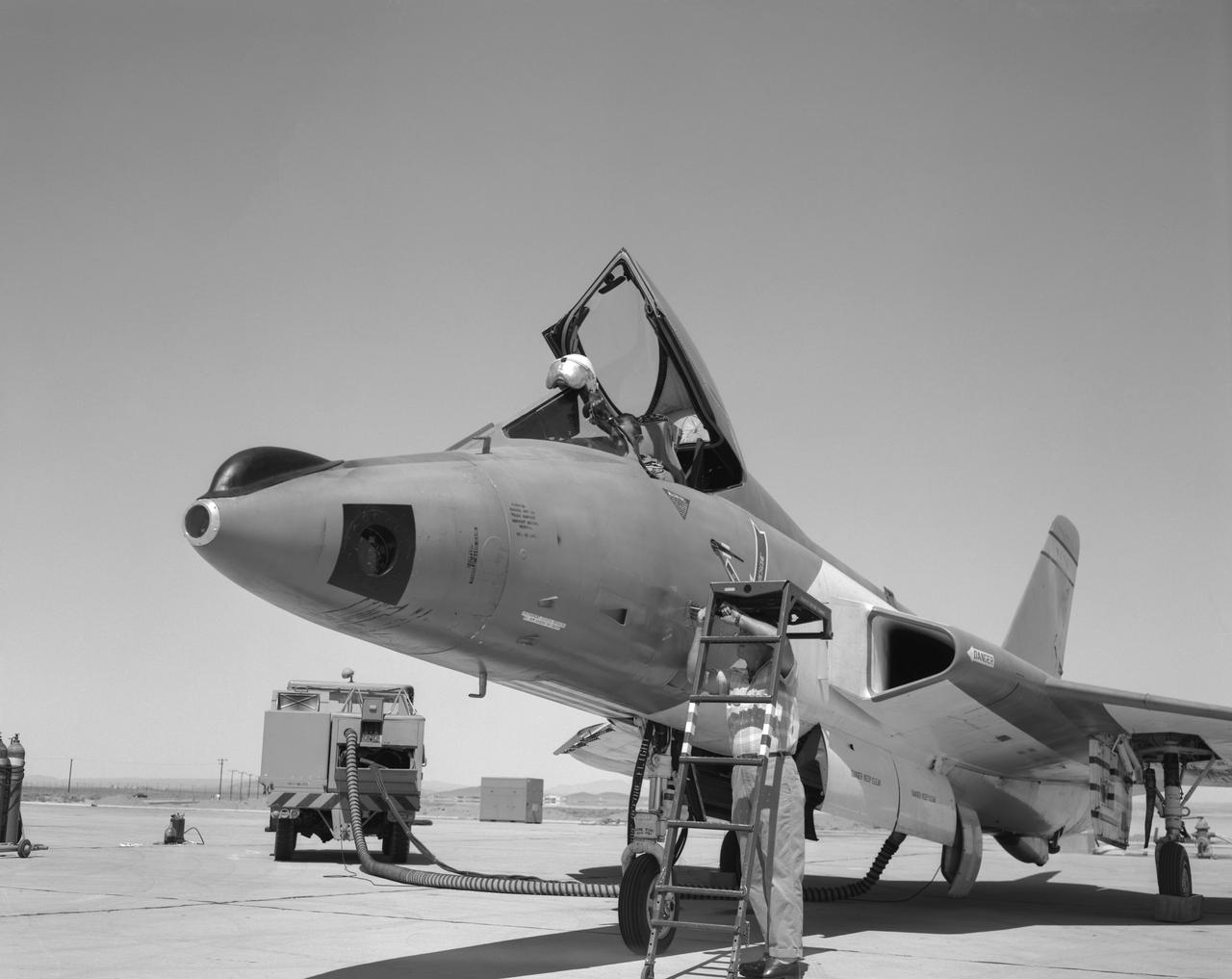
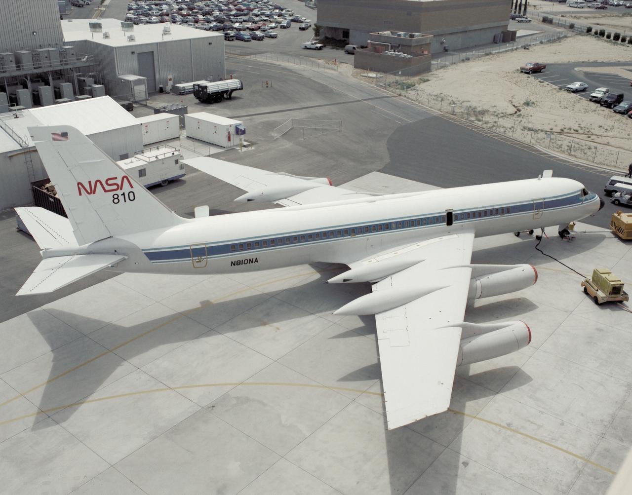
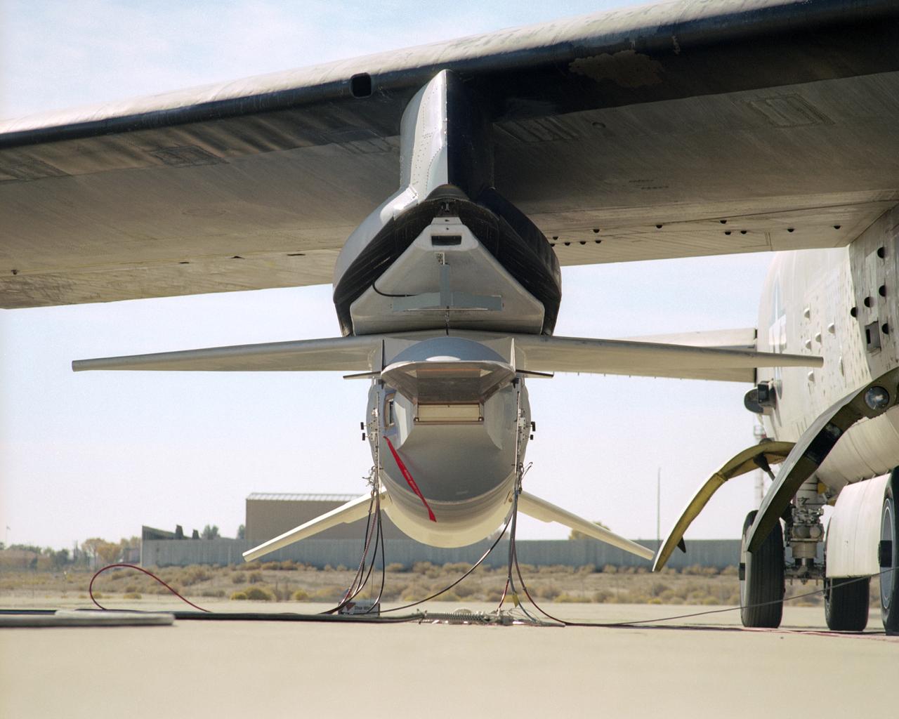
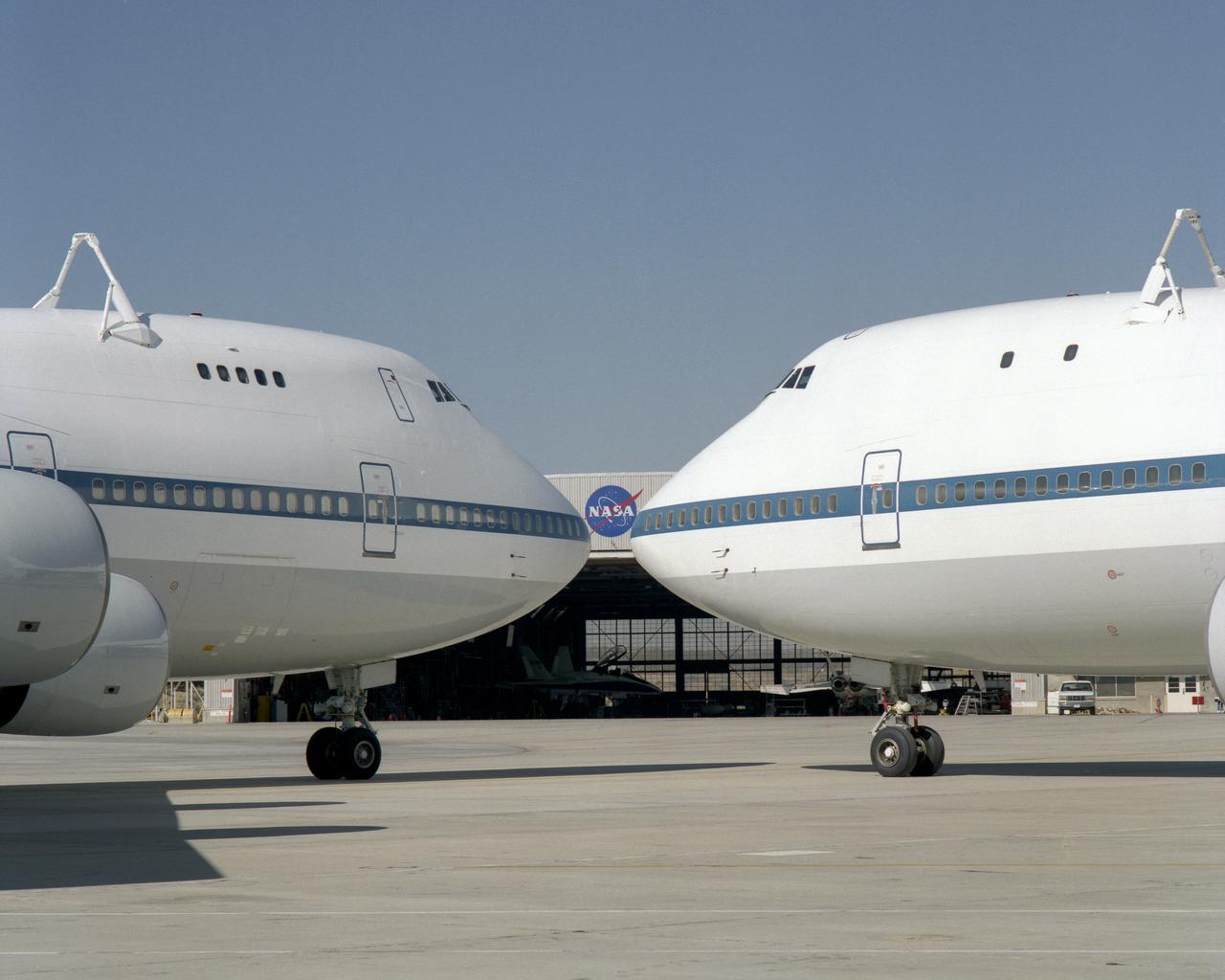
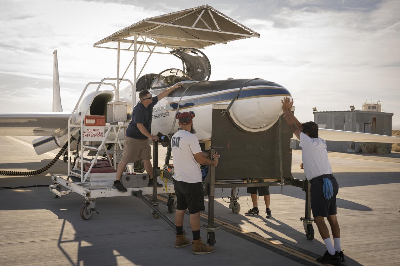
Hyperion Nose
Hyperion Nose
Moessbauer Nose Print
Event: SEG 230 Nose The X-59’s nose is wrapped up safely and rests on a dolly before the team temporarily attaches it to the aircraft for fit checks at Lockheed Martin in Palmdale, California. The full length of the X-plane’s nose is 38-feet – making up one third of the plane’s full length. The aircraft, under construction at Lockheed Martin Skunk Works in Palmdale, California, once in the air will demonstrate the ability to fly supersonic while reducing the loud sonic boom to a quiet sonic thump.
SEG 230 Nose
Event: SEG 230 Nose - Craned Onto Tooling A close up of the X-59’s duckbill nose, which is a crucial part of its supersonic design shaping. The team prepares the nose for a fit check. The X-59’s nose is 38-feet long – approximately one third of the length of the entire aircraft. The aircraft, under construction at Lockheed Martin Skunk Works in Palmdale, California, will demonstrate the ability to fly supersonic while reducing the loud sonic boom to a quiet sonic thump.
SEG 230 Nose - Craned Onto Tooling
Event: SEG 230 Nose - Craned Onto Tooling A close-up of the X-59’s duckbill nose, which is a crucial part of its supersonic design shaping. The team prepares the nose for a fit check. The X-59’s nose is 38-feet long – approximately one third of the length of the entire aircraft. The aircraft, under construction at Lockheed Martin Skunk Works in Palmdale, California, will demonstrate the ability to fly supersonic while reducing the loud sonic boom to a quiet sonic thump.
SEG 230 Nose - Craned Onto Tooling
This panoramic side view of NASA’s X-59 Quiet SuperSonic Technology airplane shows the aircraft sitting on jacks at a Lockheed Martin test facility in Fort Worth, Texas.  Lockheed Martin Aeronautics Company - Fort Worth - Chris Hanoch Subject: SEG 230 Nose Attachement FP#: 21-03420 POC: Analiese Smith, Chris Higgins Other info: X-59 in Fort Worth, testing
SEG 230 Nose Attachement
Event: Forebody and Nose - Windtunnel Testing A model of the X-59 forebody is shown in the Lockheed Martin Skunk Works’ wind tunnel in Palmdale, California. These tests gave the team measurements of wind flow angle around the aircraft’s nose and confirmed computer predictions made using computational fluid dynamics (CFD) software tools. The data will be fed into the aircraft flight control system to tell the pilot the aircraft’s altitude, speed and angle. This is part of NASA’s Quesst mission which plans to help enable supersonic air travel over land.
Forebody and Nose - Windtunnel Testing
Event: Forebody and Nose - Windtunnel Testing A technician works on the X-59 model during testing in the low-speed wind tunnel at Lockheed Martin Skunk Works in Palmdale, California. These tests gave the team measurements of wind flow angle around the aircraft’s nose and confirmed computer predictions made using computational fluid dynamics (CFD) software tools. The data will be fed into the aircraft flight control system to tell the pilot the aircraft’s altitude, speed, and angle. This is part of NASA’s Quesst mission which plans to help enable supersonic air travel over land.
Forebody and Nose - Windtunnel Testing
Event: Forebody and Nose - Windtunnel Testing A model of the X-59 forebody is shown in the Lockheed Martin Skunk Works’ wind tunnel in Palmdale, California. These tests gave the team measurements of wind flow angle around the aircraft’s nose and confirmed computer predictions made using computational fluid dynamics (CFD) software tools. The data will be fed into the aircraft flight control system to tell the pilot the aircraft’s altitude, speed and angle. This is part of NASA’s Quesst mission which plans to help enable supersonic air travel over land.
Forebody and Nose - Windtunnel Testing
Artist concept of the X-59 in flight overland and water.
X59_Flying_004-Gray-Nose-AUG
NASA Wide-field Infrared Survey Explorer is shown inside one-half of the nose cone, or fairing, that will protect it during launch.
WISE Snug in its Nose Cone
NASA Wide-field Infrared Survey Explorer is shown inside one-half of the nose cone, or fairing, that will protect it during launch.
WISE Snug in its Nose Cone
NASA Wide-field Infrared Survey Explorer is shown inside one-half of the nose cone, or fairing, that will protect it during launch.
WISE Snug in its Nose Cone
A panoramic view of NASA’s X-59 in Fort Worth, Texas to undergo structural and fuel testing.  The X-59’s nose makes up one third of the aircraft, at 38-feet in length. The X-59 is a one-of-a-kind airplane designed to fly at supersonic speeds without making a startling sonic boom sound for the communities below. This is part of NASA’s Quesst mission which plans to help enable supersonic air travel over land.
SEG 230 Nose Attachement
This is an overhead view of the X-59 aircraft at Lockheed Martin Skunk Works in Palmdale, California. The nose was installed, and the plane awaits engine installation. Technicians continue to wire the aircraft as the team preforms several system checkouts to ensure the safety of the aircraft. The X-59 aircraft will demonstrate the ability to fly supersonic while reducing the loud sonic boom to a quiet sonic thump and help enable commercial supersonic air travel over land.
From Above With Nose Installed
ROBERT CARROLL, A MACHINIST WITH LOCKHEED MARTIN, DRILLS ALIGNMENT HOLES ON THE EXTERNAL TANK COMPOSITE NOSE CONE
1000094
Engineers with NASA’s Exploration Ground Systems complete stacking operations on the twin SLS (Space Launch System) solid rocket boosters for Artemis II by integrating the nose cones atop the forward assemblies inside the Vehicle Assembly Building’s High Bay 3 at NASA’s Kennedy Space Center in Florida on Wednesday, Feb. 19, 2025. During three months of stacking operations, technicians used a massive overhead crane to lift 10 booster segments – five segments per booster – and aerodynamic nose cones into place on mobile launcher 1. The twin solid boosters will help support the remaining rocket components and the Orion spacecraft during final assembly of the Artemis II Moon rocket and provide more than 75 percent of the total SLS thrust during liftoff from NASA Kennedy’s Launch Pad 39B.
Artemis II Stacking Final Nose Cone
F5D Skylancer with camera installation in nose.
Developed by the Marshall Space Flight Center (MSFC) as an interim vehicle in MSFC’s “building block” approach to the Saturn rocket development, the Saturn IB utilized Saturn I technology to further develop and refine the larger boosters and the Apollo spacecraft capabilities required for the manned lunar missions. The Saturn IB vehicle was a two-stage rocket and had a payload capability about 50 percent greater than the Saturn I vehicle. The first stage, S-IB stage, was a redesigned first stage of the Saturn I. This photograph is of the S-IB nose cone #3 during assembly in building 4752.
Saturn Apollo Program
Outlined with gold stripes are the hinged nose strakes, modifications made to NASA's F-18 HARV (High Alpha Research Vehicle) at the Dryden Flight Research Center, Edwards, California. Actuated Nose Strakes for Enhanced Rolling (ANSER) were installed to fly the third and final phase in the HARV flight test project. Normally folded flush, the units -- four feet long and six inches wide -- can be opened independently to interact with the nose vortices to produce large side forces for control.  Early wind tunnel tests indicated that the strakes would be as effective in yaw control at high angles of attack as rudders are at lower angles. Testing involved evaluation of the strakes by themselves as well as combined with the aircraft's Thrust Vectoring System. The strakes were designed by NASA's Langley Research Center, then installed and flight tested at Dryden.
EC95-43057-8
NASA's two modified Boeing 747 Shuttle Carrier Aircraft #911 (left) and #905 (right) were nose-to-nose on the ramp at NASA Dryden in this 1995 photo.
NASA's two modified Boeing 747 Shuttle Carrier Aircraft #911 (left) and #905 (right) were nose-to-nose on the ramp at NASA Dryden in this 1995 photo
During the final phase of tests with the HARV, Dryden technicians installed nose strakes, which were panels that fitted flush against the sides of the forward nose. When the HARV was at a high alpha, the aerodynamics of the nose caused a loss of directional stability. Extending one or both of the strakes results in strong side forces that, in turn, generated yaw control. This approach, along with the aircraft's Thrust Vectoring Control system, proved to be stability under flight conditions in which conventional surfaces, such as the vertical tails, were ineffective.
EC96-43479-5
ED KIRCH, A LOCKHEED MARTIN TECHNICIAN, CUTS A PATTERN FROM COMPOSITE MATERIAL THAT WILL BE PLACED IN A MOLD TO BUILD A SPACE SHUTTLE EXTERNAL TANK COMPOSITE NOSE CONE.
1000093
ISS034-E-051551 (21 Feb. 2013) --- Cosmonaut Roman Romanenko, Expedition 34 flight engineer, works with the Electronic Nose hardware in the Zvezda service module aboard the International Space Station in Earth orbit.  This hardware is used to measure contamination in the environment should there be hard to detect chemical leaks or spills.
Romanenko works with the Electronic Nose (Enose) Hardware in the SM
NASA's Super Guppie arrives at Redstone Arsenal airfield to transport the Orion stage adapter to Denver Colorado for further testing. The nose is open exposing the cargo bay.
MSFC-1700817
A NASA CV-990, modified as a Landing Systems Research Aircraft (LSRA), is serviced on the ramp at NASA's Dryden Flight Research Center, Edwards, California, before a test of the space shuttle landing gear system. The space shuttle landing gear test unit, operated by a high-pressure hydraulic system, allowed engineers to assess and document the performance of space shuttle main and nose landing gear systems, tires and wheel assemblies, plus braking and nose wheel steering performance. The series of 155 test missions for the space shuttle program provided extensive data about the life and endurance of the shuttle tire systems and helped raise the shuttle crosswind landing limits at Kennedy.
CV-990 LSRA
Here is an overhead view of the X-59 aircraft (left) prior to the installation of the General Electric F414 engine (center, located under the blue cover). After the engine is installed, the lower empennage (right), the last remaining major aircraft component, will be installed in preparation for integrated system checkouts. The X-59 is the centerpiece of the Quesst mission which plans to help enable commercial supersonic air travel over land.
From Above With Nose Installed
At the Shuttle Landing Facility, the nose of the Beluga aircraft is open to offload its cargo, the Italian-built module, U.S. Node 2, for the International Space Station.  The second of three Station connecting modules, Node 2 attaches to the end of the U.S. Lab and provides attach locations for the Japanese laboratory, European laboratory, the Centrifuge Accommodation Module and, later, Multipurpose Logistics Modules. It will provide the primary docking location for the Shuttle when a pressurized mating adapter is attached to Node 2.  Installation of the module will complete  the U.S. Core of the ISS.  Node 2 is the designated payload for mission STS-120.  No orbiter or launch date has been determined yet.
At the Shuttle Landing Facility, the nose of the Beluga aircraft
KENNEDY SPACE CENTER, FLA. - In the Orbiter Processing Facility, Atlantis is seen after its nose cap was removed for routine inspection. The nose cap is made of reinforced carbon-carbon (RCC), which has an operating range of minus 250° F to about 3,000° F.
KENNEDY SPACE CENTER, FLA. - In the Orbiter Processing Facility, workers watch as the nose cap of the orbiter Atlantis is lowered toward the floor.   The cap was removed from the orbiter for routine inspection. The nose cap is made of reinforced carbon-carbon (RCC), which has an operating range of minus 250° F to about 3,000° F.
KENNEDY SPACE CENTER, FLA. - In the Orbiter Processing Facility, workers watch as the nose cap of the orbiter Atlantis is lowered toward the floor. The cap was removed from the orbiter for routine inspection. The nose cap is made of reinforced carbon-carbon (RCC), which has an operating range of minus 250° F to about 3,000° F.
KENNEDY SPACE CENTER, FLA. -  In the Orbiter Processing Facility, the nose cap of the orbiter Atlantis rests on a stand after its removal from the orbiter for routine inspection. The nose cap is made of reinforced carbon-carbon (RCC), which has an operating range of minus 250° F to about 3,000° F.
KENNEDY SPACE CENTER, FLA. - In the Orbiter Processing Facility, the nose cap of the orbiter Atlantis rests on a stand after its removal from the orbiter for routine inspection. The nose cap is made of reinforced carbon-carbon (RCC), which has an operating range of minus 250° F to about 3,000° F.
KENNEDY SPACE CENTER, FLA. -  In the Orbiter Processing Facility, workers secure the nose cap of the orbiter Atlantis on a stand.   The cap was removed from the orbiter for routine inspection. The nose cap is made of reinforced carbon-carbon (RCC), which has an operating range of minus 250° F to about 3,000° F.
KENNEDY SPACE CENTER, FLA. - In the Orbiter Processing Facility, workers secure the nose cap of the orbiter Atlantis on a stand. The cap was removed from the orbiter for routine inspection. The nose cap is made of reinforced carbon-carbon (RCC), which has an operating range of minus 250° F to about 3,000° F.
KENNEDY SPACE CENTER, FLA. - In the Orbiter Processing Facility, workers watch as the nose cap of the orbiter Atlantis is shifted to a horizontal position on a stand.  The cap was removed from the orbiter for routine inspection. The nose cap is made of reinforced carbon-carbon (RCC), which has an operating range of minus 250° F to about 3,000° F.
KENNEDY SPACE CENTER, FLA. - In the Orbiter Processing Facility, workers watch as the nose cap of the orbiter Atlantis is shifted to a horizontal position on a stand. The cap was removed from the orbiter for routine inspection. The nose cap is made of reinforced carbon-carbon (RCC), which has an operating range of minus 250° F to about 3,000° F.
KENNEDY SPACE CENTER, FLA. -  In the Orbiter Processing Facility, the nose cap from Atlantis is secured on a shipping pallet.  The reinforced carbon-carbon (RCC) nose cap is being sent to the original manufacturing company, Vought in Ft. Worth, Texas, a subsidiary of Lockheed Martin, to undergo non-destructive testing such as CAT scan and thermography.
KENNEDY SPACE CENTER, FLA. - In the Orbiter Processing Facility, the nose cap from Atlantis is secured on a shipping pallet. The reinforced carbon-carbon (RCC) nose cap is being sent to the original manufacturing company, Vought in Ft. Worth, Texas, a subsidiary of Lockheed Martin, to undergo non-destructive testing such as CAT scan and thermography.
KENNEDY SPACE CENTER, FLA. - In the Orbiter Processing Facility, Atlantis is seen after its nose cap was removed for routine inspection. The nose cap is made of reinforced carbon-carbon (RCC), which has an operating range of minus 250° F to about 3,000° F.
KENNEDY SPACE CENTER, FLA. - In the Orbiter Processing Facility, the nose cap of the orbiter Atlantis is lifted for its transfer to a stand.  The cap was removed for routine inspection. The nose cap is made of reinforced carbon-carbon (RCC), which has an operating range of minus 250° F to about 3,000° F.
KENNEDY SPACE CENTER, FLA. - In the Orbiter Processing Facility, the nose cap of the orbiter Atlantis is lifted for its transfer to a stand. The cap was removed for routine inspection. The nose cap is made of reinforced carbon-carbon (RCC), which has an operating range of minus 250° F to about 3,000° F.
KENNEDY SPACE CENTER, FLA. -  In the Orbiter Processing Facility, STS-114 Commander Eileen Collins examines part of the Atlantis nose cap with Randall Carter, who is with The  Boeing Company.  The nose cap was  recently removed from Atlantis.  The STS-114 crew is at KSC to take part in crew equipment and orbiter familiarization.
KENNEDY SPACE CENTER, FLA. - In the Orbiter Processing Facility, STS-114 Commander Eileen Collins examines part of the Atlantis nose cap with Randall Carter, who is with The Boeing Company. The nose cap was recently removed from Atlantis. The STS-114 crew is at KSC to take part in crew equipment and orbiter familiarization.
KENNEDY SPACE CENTER, FLA. -  In the Orbiter Processing Facility, workers help guide the nose cap of the orbiter Atlantis toward a stand.  The cap was removed from the orbiter for routine inspection. The nose cap is made of reinforced carbon-carbon (RCC), which has an operating range of minus 250° F to about 3,000° F.
KENNEDY SPACE CENTER, FLA. - In the Orbiter Processing Facility, workers help guide the nose cap of the orbiter Atlantis toward a stand. The cap was removed from the orbiter for routine inspection. The nose cap is made of reinforced carbon-carbon (RCC), which has an operating range of minus 250° F to about 3,000° F.
KENNEDY SPACE CENTER, FLA. - In the Orbiter Processing Facility, workers watch as the nose cap of the orbiter Atlantis is moved toward the stand at left.  The cap was removed from the orbiter for routine inspection. The nose cap is made of reinforced carbon-carbon (RCC), which has an operating range of minus 250° F to about 3,000° F.
KENNEDY SPACE CENTER, FLA. - In the Orbiter Processing Facility, workers watch as the nose cap of the orbiter Atlantis is moved toward the stand at left. The cap was removed from the orbiter for routine inspection. The nose cap is made of reinforced carbon-carbon (RCC), which has an operating range of minus 250° F to about 3,000° F.
KENNEDY SPACE CENTER, FLA. -  In the Orbiter Processing Facility, the nose cap from Atlantis is lowered toward a shipping pallet.  The reinforced carbon-carbon (RCC) nose cap is being sent to the original manufacturing company, Vought in Ft. Worth, Texas, a subsidiary of Lockheed Martin, to undergo non-destructive testing such as CAT scan and thermography.
KENNEDY SPACE CENTER, FLA. - In the Orbiter Processing Facility, the nose cap from Atlantis is lowered toward a shipping pallet. The reinforced carbon-carbon (RCC) nose cap is being sent to the original manufacturing company, Vought in Ft. Worth, Texas, a subsidiary of Lockheed Martin, to undergo non-destructive testing such as CAT scan and thermography.
KENNEDY SPACE CENTER, FLA. - In the Orbiter Processing Facility, workers remove the nose cone of the orbiter Atlantis for routine inspection. The nose cap is made of reinforced carbon-carbon (RCC), which has an operating range of minus 250° F to about 3,000° F.
KENNEDY SPACE CENTER, FLA. - In the Orbiter Processing Facility, the nose cap of the orbiter Atlantis is shifted to a horizontal position on a stand.  The cap was removed from the orbiter for routine inspection. The nose cap is made of reinforced carbon-carbon (RCC), which has an operating range of minus 250° F to about 3,000° F.
KENNEDY SPACE CENTER, FLA. - In the Orbiter Processing Facility, the nose cap of the orbiter Atlantis is shifted to a horizontal position on a stand. The cap was removed from the orbiter for routine inspection. The nose cap is made of reinforced carbon-carbon (RCC), which has an operating range of minus 250° F to about 3,000° F.
KENNEDY SPACE CENTER, FLA. - In the Orbiter Processing Facility, workers secure the nose cap of the orbiter Atlantis for its transfer to a stand.  The cap was removed for routine inspection. The nose cap is made of reinforced carbon-carbon (RCC), which has an operating range of minus 250° F to about 3,000° F.
KENNEDY SPACE CENTER, FLA. - In the Orbiter Processing Facility, workers secure the nose cap of the orbiter Atlantis for its transfer to a stand. The cap was removed for routine inspection. The nose cap is made of reinforced carbon-carbon (RCC), which has an operating range of minus 250° F to about 3,000° F.
Engineers with NASA’s Exploration Ground Systems integrate the aerodynamic nose cone onto the right-hand forward assembly of the twin SLS (Space Launch System) solid rocket boosters for Artemis II inside the Vehicle Assembly Building’s High Bay 3 at NASA’s Kennedy Space Center in Florida on Tuesday, Feb. 18, 2025. Each forward assembly contains an aerodynamic top, a forward skirt housing avionics, and frustum housing motors that allow the boosters to separate from the SLS core stage after launch. The twin solid boosters will help support the remaining rocket components and the Orion spacecraft during final assembly of the Artemis II Moon rocket and provide more than 75 percent of the total SLS thrust during liftoff from NASA Kennedy’s Launch Pad 39B.
Artemis II Stacking Nose Cone RH preps
Engineers with NASA’s Exploration Ground Systems integrate the aerodynamic nose cone onto the left-hand forward assembly on the twin SLS (Space Launch System) solid rocket boosters for Artemis II inside the Vehicle Assembly Building’s High Bay 3 at NASA’s Kennedy Space Center in Florida on Tuesday, Feb. 18, 2025. Each forward assembly contains an aerodynamic top, a forward skirt housing avionics, and frustum housing motors that allow the boosters to separate from the SLS core stage after launch. The twin solid boosters will help support the remaining rocket components and the Orion spacecraft during final assembly of the Artemis II Moon rocket and provide more than 75 percent of the total SLS thrust during liftoff from NASA Kennedy’s Launch Pad 39B.
Artemis II Stacking Nose Cone LH mate
Engineers with NASA’s Exploration Ground Systems integrate the aerodynamic nose cone onto the right-hand forward assembly of the twin SLS (Space Launch System) solid rocket boosters for Artemis II inside the Vehicle Assembly Building’s High Bay 3 at NASA’s Kennedy Space Center in Florida on Tuesday, Feb. 18, 2025. Each forward assembly contains an aerodynamic top, a forward skirt housing avionics, and frustum housing motors that allow the boosters to separate from the SLS core stage after launch. The twin solid boosters will help support the remaining rocket components and the Orion spacecraft during final assembly of the Artemis II Moon rocket and provide more than 75 percent of the total SLS thrust during liftoff from NASA Kennedy’s Launch Pad 39B.
Artemis II Stacking Nose Cone RH preps
Engineers with NASA’s Exploration Ground Systems integrate the aerodynamic nose cone onto the left-hand forward assembly on the twin SLS (Space Launch System) solid rocket boosters for Artemis II inside the Vehicle Assembly Building’s High Bay 3 at NASA’s Kennedy Space Center in Florida on Tuesday, Feb. 18, 2025. Each forward assembly contains an aerodynamic top, a forward skirt housing avionics, and frustum housing motors that allow the boosters to separate from the SLS core stage after launch. The twin solid boosters will help support the remaining rocket components and the Orion spacecraft during final assembly of the Artemis II Moon rocket and provide more than 75 percent of the total SLS thrust during liftoff from NASA Kennedy’s Launch Pad 39B.
Artemis II Stacking Nose Cone LH mate
S66-54656 (13 Sept. 1966) --- Nose of Gemini-11 spacecraft and Agena Target Vehicle while docked as photographed by astronaut Richard F. Gordon Jr., pilot, during his stand-up extravehicular activity (EVA). Taken with a modified 70mm Hasselblad camera, using Eastman Kodak, Ektachrome, MS (S.O. 368) color film. Photo credit: NASA
Nose of Gemini 11 spacecraft and Agena Target Vehicle as seen during EVA
The NASA logo on a hangar is framed by the noses of NASA's two modified 747 Shuttle Carrier Aircraft on the ramp at NASA Dryden in this 1995 photo.
The NASA logo on a hangar is framed by the noses of NASA's two modified 747 Shuttle Carrier Aircraft on the ramp at NASA Dryden in this 1995 photo
The small size of the X-43A scramjet is evident in this nose-on view while mounted to its modified Pegasus booster under the wing of NASA's B-52B mothership.
The small size of the X-43A scramjet is evident in this nose-on view while mounted to its modified Pegasus booster under the wing of NASA's B-52B mothership
NASA Dawn spacecraft solar array wings are folded to fit inside nose section of protective fairing.
Dawn Spacecraft Ready for Payload Fairing Installation
NASA Dryden aircraft and avionics technicians (from left) Bryan Hookland, Art Cope, Herman Rijfkogel and Jonathan Richards install the nose cone on a Phoenix missile prior to a fit check on the center's F-15B research aircraft.
NASA Dryden aircraft and avionics technicians install the nose cone on an inert Phoenix missile prior to a fit check on the center's F-15B research aircraft.
Crew members reattach the nose cone of NASA’s Armstrong Flight Research Center’s ER-2 aircraft at Edwards, California, on Thursday, Aug. 21, 2025, ahead of a mission for the Geological Earth Mapping Experiment (GEMx). The aircraft’s nose houses key science instruments used to collect data during flight.
NASA ER-2 Flies Geological Mapping Mission
KENNEDY SPACE CENTER, FLA. -  In the Orbiter Processing Facility, packing material is placed over the nose cap that was removed from Atlantis.   The reinforced carbon-carbon (RCC) nose cap is being sent to the original manufacturing company, Vought in Ft. Worth, Texas, a subsidiary of Lockheed Martin, to undergo non-destructive testing such as CAT scan and thermography.
KENNEDY SPACE CENTER, FLA. - In the Orbiter Processing Facility, packing material is placed over the nose cap that was removed from Atlantis. The reinforced carbon-carbon (RCC) nose cap is being sent to the original manufacturing company, Vought in Ft. Worth, Texas, a subsidiary of Lockheed Martin, to undergo non-destructive testing such as CAT scan and thermography.
KENNEDY SPACE CENTER, FLA. -  In the Orbiter Processing Facility, workers remove the overhead crane from the nose cap that was removed from Atlantis.   The reinforced carbon-carbon (RCC) nose cap is being sent to the original manufacturing company, Vought in Ft. Worth, Texas, a subsidiary of Lockheed Martin, to undergo non-destructive testing such as CAT scan and thermography.
KENNEDY SPACE CENTER, FLA. - In the Orbiter Processing Facility, workers remove the overhead crane from the nose cap that was removed from Atlantis. The reinforced carbon-carbon (RCC) nose cap is being sent to the original manufacturing company, Vought in Ft. Worth, Texas, a subsidiary of Lockheed Martin, to undergo non-destructive testing such as CAT scan and thermography.
S114-E-6194 (3 August 2005) --- This picture of the forward section of the Space Shuttle Discovery docked to the International Space Station was taken by Japan Aerospace Exploration Agency Astronaut Soichi Noguchi during the third and final spacewalk for the STS-114 mission.  Both Noguchi and his crewmate Astronaut Stephen K. Robinson were equipped with digital still cameras on the spacewalks.
Discovery forward nose cone
This image shows the forward view of the X-59’s cockpit with the canopy open. The aircraft will not have a forward-facing window and will use an eXternal Vision System (XVS) made up of a high definition 4K monitor (located in the center) and two monitors below to help the pilots safely fly through the skies.
Nose Installed and Cockpit Instrumentation
A spacecraft technician is performing closeout work inside the fairing that will be installed around NASA Nuclear Spectroscopic Telescope Array NuSTAR spacecraft in a processing facility at Vandenberg Air Force Base in California.
Inside NuSTAR Nose Cone
L57-5383 Hot-air jets employing ceramic heat exchangers played an important role at Langley in the study of materials for ballistic missile nose cones and re-entry vehicles. Here a model is being tested in one of theses jets at 4000 degrees Fahrenheit in 1957. Photograph published in Engineer in Charge: A History of the Langley Aeronautical Laboratory, 1917-1958 by James R. Hansen. Page 477.
Hot-Air Jets/Ceramic Heat Exchangers/ Materials for Nose Cones and Reentry Vehicles
Event: Manufacturing Area From Above  A overhead view of the X-59 with its nose on. The X-59’s nose is 38-feet long – approximately one third of the length of the entire aircraft. The aircraft, under construction at Lockheed Martin Skunk Works in Palmdale, California, will demonstrate the ability to fly supersonic while reducing the loud sonic boom to a quiet sonic thump.
Manufacturing Area From Above
The X-59 arrives home in Palmdale, California after completing important structural and fuel tests at the Lockheed Martin facility in Ft. Worth, Texas. The nose, which is not installed in this image, was removed prior to the transport home and arrived separately to the facility. This is part of NASA’s Quesst mission which plans to help enable supersonic air travel over land.
LRC-2022-H1_P_X-59-1
A overhead view of the X-59 with its nose on. The X-59’s nose is 38-feet long – approximately one third of the length of the entire aircraft. The plane is under construction at Lockheed Martin Skunk Works in Palmdale, California, will fly to demonstrate the ability to fly supersonic while reducing the loud sonic boom to a quiet sonic thump.
Manufacturing Area From Above
A panoramic side view of the left top of the X-59 supersonic plane with the tail on and the nose in the process of installation. The X-59’s nose is 38-feet long – approximately one third of the length of the entire aircraft. The aircraft, under construction at Lockheed Martin Skunk Works in Palmdale, California, will demonstrate the ability to fly supersonic while reducing the loud sonic boom to a quiet sonic thump.
Manufacturing Area From Above
An overhead view of the X-59 supersonic plane with the tail on and the nose in the process of installation. The X-59’s nose is 38-feet long – approximately one third of the length of the entire aircraft. The aircraft, under construction at Lockheed Martin Skunk Works in Palmdale, California, will demonstrate the ability to fly supersonic while reducing the loud sonic boom to a quiet sonic thump.
Manufacturing Area From Above
STS081-E-05436 (15 Jan. 1997) --- Soon after the astronauts docked the space shuttle Atlantis with Russia's Mir Space Station, astronaut Marsha S. Ivins, STS-81 mission specialist, went aboard the Mir complex and sought a window through which she could record this image of Atlantis' forward section. A solar array panel on the Mir is seen in one corner and the Ku-band antenna for Atlantis is visible in another. This view was taken with an electronic still camera (ESC). Photo credit: NASA
View of orbiter nose and earth limb
This test for the radar system to be used during the August 2012 descent and landing of NASA Mars rover Curiosity mounted an engineering test model of the radar system onto the nose of a helicopter.
Test at NASA Dryden of Radar System for Next Mars Landing
This image from the NASA/ESA Hubble Space Telescope shows a galaxy cluster, SDSS J1038+4849, that appears to have two eyes and a nose as part of a happy face. The face is the result of gravitational lensing.
Smile, and the Universe Smiles With You
In advance of a testing flight at NASA Dryden Flight Research Center, members of the test team prepare the engineering model of the Mars Science Laboratory descent radar on the nose gimbal of a helicopter. The yellow disks are the radar antennae.
Preparing for a Mars Radar Test
Do you see what I see in this image from NASA Mars Odyssey spacecraft? The eyes and nose of a giant man glares from the top of this nighttime infrared image.
THEMIS Art #111
KENNEDY SPACE CENTER, FLA. -   In Orbiter Processing Facility bay 2 at NASA's Kennedy Space Center, workers maneuver the reinforced carbon-carbon nose cap as it is hoisted into the air.  The nose cap will be installed on Endeavour.  The nose cap is insulated with thermal protection system blankets made of a woven ceramic fabric.  The special blankets help insulate the vehicle's nose cap and protect it from the extreme temperatures it will face during a mission. Photo credit: NASA/Jim Grossmann
KSC-06pd0576
Workers watch as the nose cap of orbiter Endeavour is lowered after removal for routine inspection. The nose cap is made of reinforced carbon-carbon (RCC). The RCC has an operating range of minus 250° F to about 3,000° F.
Delta II - SIRTF Lift and Mate
The nose cap of orbiter Endeavour is being removed for routine inspection. The nose cap is made of reinforced carbon-carbon (RCC). The RCC has an operating range of minus 250° F to about 3,000° F.
Delta II - SIRTF Lift and Mate
Workers look at orbiter Endeavour after the nose cap was removed for routine inspection. The nose cap is made of reinforced carbon-carbon (RCC). The RCC has an operating range of minus 250° F to about 3,000° F.
Delta II - SIRTF Lift and Mate
KENNEDY SPACE CENTER, FLA. -  In the Orbiter Processing Facility, STS-114 Mission Specialists Charles Camarda and Andy Thomas, who were recently added to the crew, look at the nose cap recently removed from Atlantis.  The STS-114 crew is at KSC to take part in crew equipment and orbiter familiarization.
KENNEDY SPACE CENTER, FLA. - In the Orbiter Processing Facility, STS-114 Mission Specialists Charles Camarda and Andy Thomas, who were recently added to the crew, look at the nose cap recently removed from Atlantis. The STS-114 crew is at KSC to take part in crew equipment and orbiter familiarization.
KENNEDY SPACE CENTER, FLA. - In the Orbiter Processing Facility, United Space Alliance technician Jamie Haynes does a gap test on the tiles of the nose of orbiter Atlantis as part of return-to-flight activities.  Atlantis is scheduled for mission STS-114, a return-to-flight test mission to the International Space Station.
KENNEDY SPACE CENTER, FLA. - In the Orbiter Processing Facility, United Space Alliance technician Jamie Haynes does a gap test on the tiles of the nose of orbiter Atlantis as part of return-to-flight activities. Atlantis is scheduled for mission STS-114, a return-to-flight test mission to the International Space Station.
KENNEDY SPACE CENTER, FLA. - In the Orbiter Processing Facility, United Space Alliance technician Chris Moore performs gap tests on the tiles of the nose of orbiter Atlantis as part of return-to-flight activities.  Atlantis is scheduled for mission STS-114, a return-to-flight test mission to the International Space Station.
KENNEDY SPACE CENTER, FLA. - In the Orbiter Processing Facility, United Space Alliance technician Chris Moore performs gap tests on the tiles of the nose of orbiter Atlantis as part of return-to-flight activities. Atlantis is scheduled for mission STS-114, a return-to-flight test mission to the International Space Station.
KENNEDY SPACE CENTER, FLA. -  In the Orbiter Processing Facility, United Space Alliance technician Jamie Haynes checks the tiles on the nose of orbiter Atlantis as part of return-to-flight activities.  Atlantis is scheduled for mission STS-114, a return-to-flight test mission to the International Space Station.
KENNEDY SPACE CENTER, FLA. - In the Orbiter Processing Facility, United Space Alliance technician Jamie Haynes checks the tiles on the nose of orbiter Atlantis as part of return-to-flight activities. Atlantis is scheduled for mission STS-114, a return-to-flight test mission to the International Space Station.
KENNEDY SPACE CENTER, FLA. -  In the Orbiter Processing Facility, STS-114 Pilot James Kelly (center) and Mission Specialist Wendy Lawrence, who was recently added to the mission crew, look at the nose cap recently removed from Atlantis. The STS-114 crew is at KSC to take part in equipment familiarization.
KENNEDY SPACE CENTER, FLA. - In the Orbiter Processing Facility, STS-114 Pilot James Kelly (center) and Mission Specialist Wendy Lawrence, who was recently added to the mission crew, look at the nose cap recently removed from Atlantis. The STS-114 crew is at KSC to take part in equipment familiarization.
KENNEDY SPACE CENTER, FLA. - Workers in the Orbiter Processing Facility get ready to remove Ground Support Equipment used to install Discovery’s nose cap on Friday.  The nose cap had been removed from the vehicle in the summer of 2003 and returned to the vendor, where it underwent numerous forms of Non-Destructive Evaluation. These tests included X-ray, ultrasound and eddy current to ensure its structural integrity prior to installation on the vehicle. The nose cap was also recoated. Once returned to KSC, new Thermal Protection System blankets were assembled inside of the nose cap and thermography was performed prior to installation on the orbiter.
KSC-04pd0964
KENNEDY SPACE CENTER, FLA. - Workers in the Orbiter Processing Facility remove Ground Support Equipment used to install Discovery’s nose cap on Friday.  The nose cap had been removed from the vehicle in the summer of 2003 and returned to the vendor, where it underwent numerous forms of Non-Destructive Evaluation. These tests included X-ray, ultrasound and eddy current to ensure its structural integrity prior to installation on the vehicle. The nose cap was also recoated. Once returned to KSC, new Thermal Protection System blankets were assembled inside of the nose cap and thermography was performed prior to installation on the orbiter.
KSC-04pd0965
The payload fairing, or nose cone, containing the Mars 2020 Perseverance rover sits atop the motorized payload transporter that will carry it to Space Launch Complex 41 on Cape Canaveral Air Force Station in Florida. The image was taken on July 7, 2020.  https://photojournal.jpl.nasa.gov/catalog/PIA23985
Perseverance on the Move
KENNEDY SPACE CENTER, FLA. -   The reinforced carbon-carbon nose cap has been installed on Endeavour in Orbiter Processing Facility bay 2 at NASA's Kennedy Space Center. The nose cap has been insulated with thermal protection system blankets made of a woven ceramic fabric.  The special blankets help insulate the vehicle's nose cap and protect it from the extreme temperatures it will face during a mission. Photo credit: NASA/Jim Grossmann
KSC-06pd0580
KENNEDY SPACE CENTER, FLA. -   In Orbiter Processing Facility bay 2 at NASA's Kennedy Space Center, Endeavour waits for installation of its reinforced carbon-carbon nose cap.  The nose cap is insulated with thermal protection system blankets made of a woven ceramic fabric.  The special blankets help insulate the vehicle's nose cap and protect it from the extreme temperatures it will face during a mission.  Photo credit: NASA/Jim Grossmann
KSC-06pd0573
KENNEDY SPACE CENTER, FLA. -   In Orbiter Processing Facility bay 2 at NASA's Kennedy Space Center, a worker examines the underside of the reinforced carbon-carbon nose cap that will be installed on Endeavour.  The nose cap is insulated with thermal protection system blankets made of a woven ceramic fabric.  The special blankets help insulate the vehicle's nose cap and protect it from the extreme temperatures it will face during a mission. Photo credit: NASA/George Shelton
KSC-06pd0577
KENNEDY SPACE CENTER, FLA. -  In Orbiter Processing Facility bay 2 at NASA's Kennedy Space Center, the reinforced carbon-carbon nose cap has been installed on Endeavour.  The nose cap has been insulated with thermal protection system blankets made of a woven ceramic fabric.  The special blankets help insulate the vehicle's nose cap and protect it from the extreme temperatures it will face during a mission. Photo credit: NASA/Jim Grossmann
KSC-06pd0578
KENNEDY SPACE CENTER, FLA. -   In Orbiter Processing Facility bay 2 at NASA's Kennedy Space Center, workers are nearby as a crane lifts the reinforced carbon-carbon nose cap to be installed onto Endeavour.  The nose cap is insulated with thermal protection system blankets made of a woven ceramic fabric.  The special blankets help insulate the vehicle's nose cap and protect it from the extreme temperatures it will face during a mission. Photo credit: NASA/Jim Grossmann
KSC-06pd0575
KENNEDY SPACE CENTER, FLA. -  In Orbiter Processing Facility bay 2 at NASA's Kennedy Space Center, a worker checks the reinforced carbon-carbon nose cap after installation on Endeavour.  The nose cap has been insulated with thermal protection system blankets made of a woven ceramic fabric.  The special blankets help insulate the vehicle's nose cap and protect it from the extreme temperatures it will face during a mission. Photo credit: NASA/Jim Grossmann
KSC-06pd0579
KENNEDY SPACE CENTER, FLA. -   In Orbiter Processing Facility bay 2 at NASA's Kennedy Space Center, workers are preparing to move and install the reinforced carbon-carbon nose cap (on the stand) onto Endeavour.  The nose cap is insulated with thermal protection system blankets made of a woven ceramic fabric.  The special blankets help insulate the vehicle's nose cap and protect it from the extreme temperatures it will face during a mission.  Photo credit: NASA/Jim Grossmann
KSC-06pd0574
On May 28, 1959, a Jupiter Intermediate Range Ballistic Missile provided by a U.S. Army team in Redstone Arsenal, Alabama, launched a nose cone carrying Baker, A South American squirrel monkey and Able, An American-born rhesus monkey. This photograph shows Able after recovery of the nose cone of the Jupiter rocket by U.S.S. Kiowa.
Early Rockets
STS079-335-025 (16-26 Sept. 1996) --- Astronaut Jerome (Jay) Apt, in the flight engineer's cabin aboard Russia's Mir Space Station, appears nose to nose with the space shuttle Atlantis as he peers through a viewing port at the forward section of the Orbiter while the two spacecraft were docked in Earth-orbit.
STS-79 and Mir 22 crew aboard the Mir space station
Nose camera for the X59 is being prepared for testing on the B200 King Air.
Testing of the External Vision System (XVS) Software on the B200 King Air
An Orbital Sciences technician completes final checks of NASA Nuclear Spectroscopic Telescope Array, or NuSTAR, before the Pegasus payload fairing is secured around it.
Wrapping NuSTAR in Its Rocket Nose Cone
KENNEDY SPACE CENTER, FLA. - In the Orbiter Processing Facility, workers lower the nose cap toward the orbiter Atlantis for installation. The nose cap was removed from the vehicle in May and sent back to the vendor for thorough Non-Destructive Engineering evaluation and recoating.  Thermography was also performed to check for internal flaws.  This procedure uses high intensity light to heat areas that are immediately scanned with an infrared camera.  White Thermal Protection System blankets were reinstalled on the nose cap before installation.  Processing continues on Atlantis for its future mission to the International Space Station.
KSC-04pd1678
KENNEDY SPACE CENTER, FLA. - In the Orbiter Processing Facility, workers help install the nose cap on the orbiter Atlantis. The nose cap was removed from the vehicle in May and sent back to the vendor for thorough Non-Destructive Engineering evaluation and recoating.  Thermography was also performed to check for internal flaws.  This procedure uses high intensity light to heat areas that are immediately scanned with an infrared camera.  White Thermal Protection System blankets were reinstalled on the nose cap before installation.  Processing continues on Atlantis for its future mission to the International Space Station.
KSC-04pd1679
KENNEDY SPACE CENTER, FLA. - In the Orbiter Processing Facility, workers help guide the nose cap (right) toward the orbiter Atlantis for installation. The nose cap was removed from the vehicle in May and sent back to the vendor for thorough Non-Destructive Engineering evaluation and recoating.  Thermography was also performed to check for internal flaws.  This procedure uses high intensity light to heat areas that are immediately scanned with an infrared camera.  White Thermal Protection System blankets were reinstalled on the nose cap before installation.  Processing continues on Atlantis for its future mission to the International Space Station.
KSC-04pd1680
KENNEDY SPACE CENTER, FLA. - In the Orbiter Processing Facility, workers check the fit of the nose cap (right) after installation on the orbiter Atlantis.  The nose cap was removed from the vehicle in May and sent back to the vendor for thorough Non-Destructive Engineering evaluation and recoating.  Thermography was also performed to check for internal flaws.  This procedure uses high intensity light to heat areas that are immediately scanned with an infrared camera.  White Thermal Protection System blankets were reinstalled on the nose cap before installation.  Processing continues on Atlantis for its future mission to the International Space Station.
KSC-04pd1682