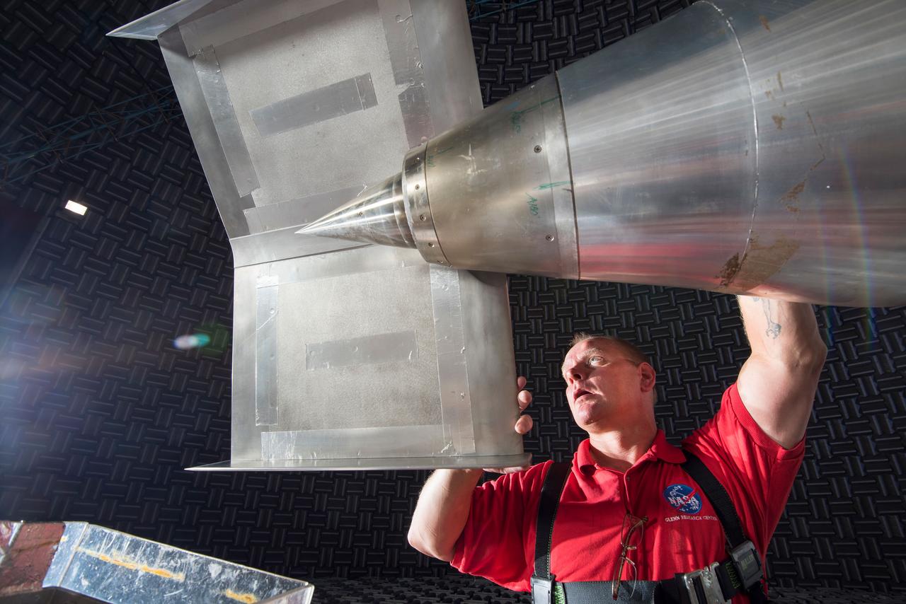
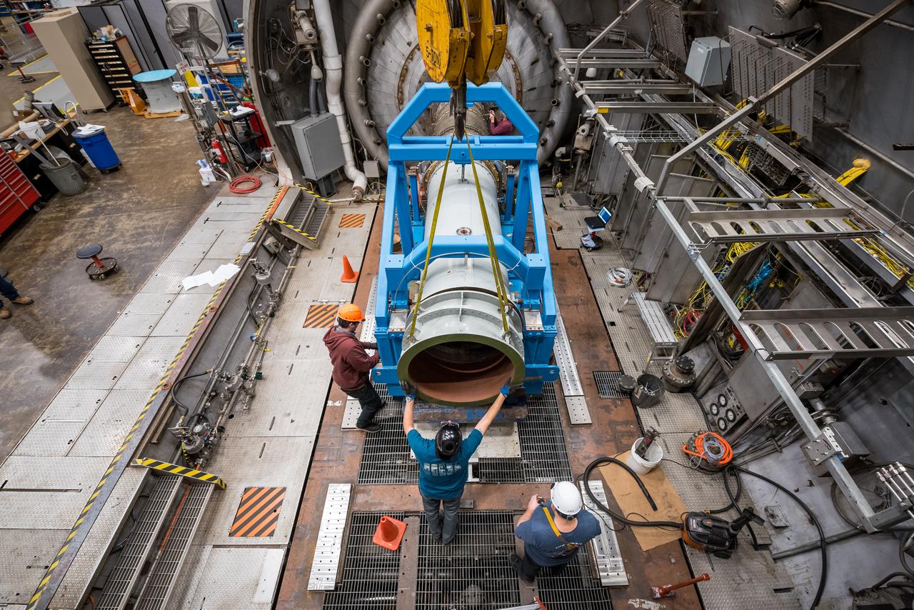
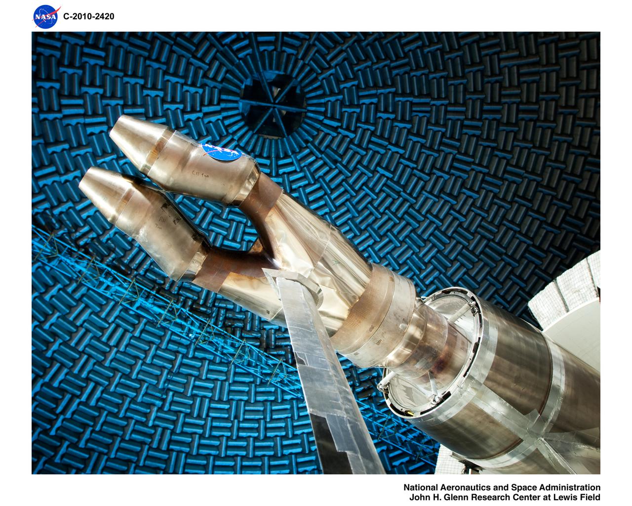
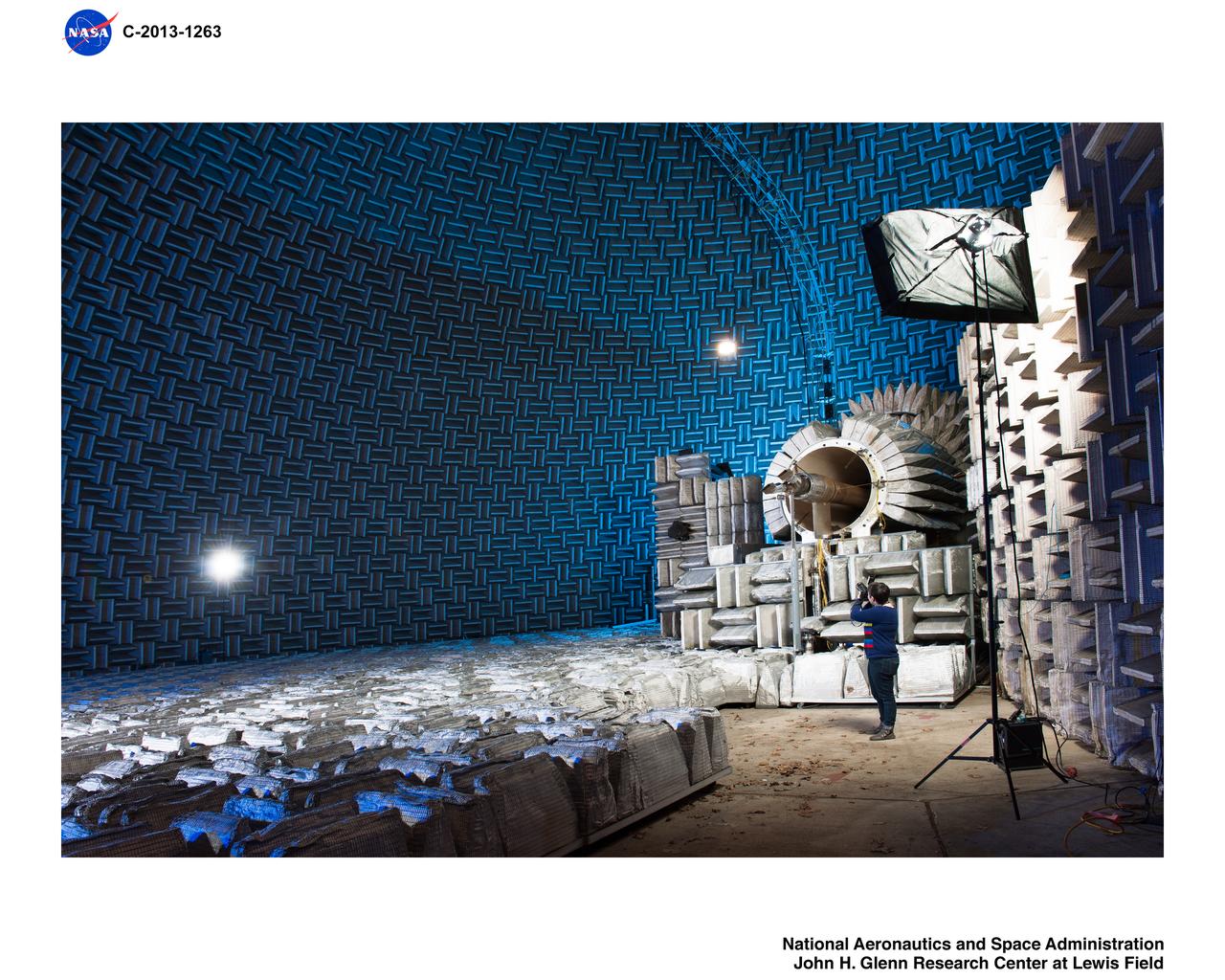
N+2 Nozzle in the Aero-Acoustic Propulsion Lab. As NASA works toward demonstrating low-sonic boom design, engineers at NASA Glenn have tested an engine nozzle that could make supersonic aircraft much quieter.
N+2 Nozzle in the Aero-Acoustic Propulsion Lab. As NASA works toward demonstrating low-sonic boom design, engineers at NASA Glenn have tested an engine nozzle that could make supersonic aircraft much quieter.
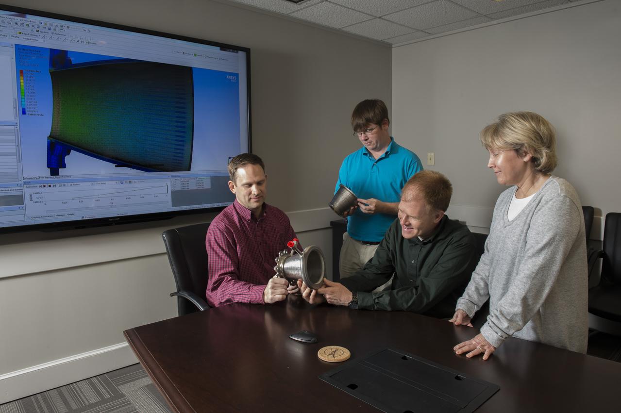
Engineers from NASA Marshall Space Flight Center's Propulsion Department examine nozzles fabricated using a freeform-directed energy wire deposition process. From left are Paul Gradl, Will Brandsmeier, Ian Johnston and Sandy Greene, with the nozzles, which were built using a NASA-patented technology that has the potential to reduce build time from several months to several weeks.
15 DEGREE CONICAL NOZZLE - TITAN TRANSTAGE CONTOUR ENGINE - APOLLO
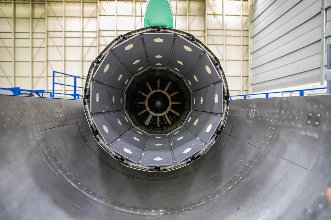
A look at the X-59’s engine nozzle, where the thrust -the force that moves the aircraft- will exit. Once complete, the X-59 is designed to fly supersonic while reducing the loud sonic boom. The Quesst mission could help change the rules for commercial supersonic air travel over land.
American Society of Mechanical Engineers, ASME Nozzle Test at Propulsion Systems Laboratory, PSL
American Society of Mechanical Engineers, ASME Nozzle Test at Propulsion Systems Laboratory, PSL
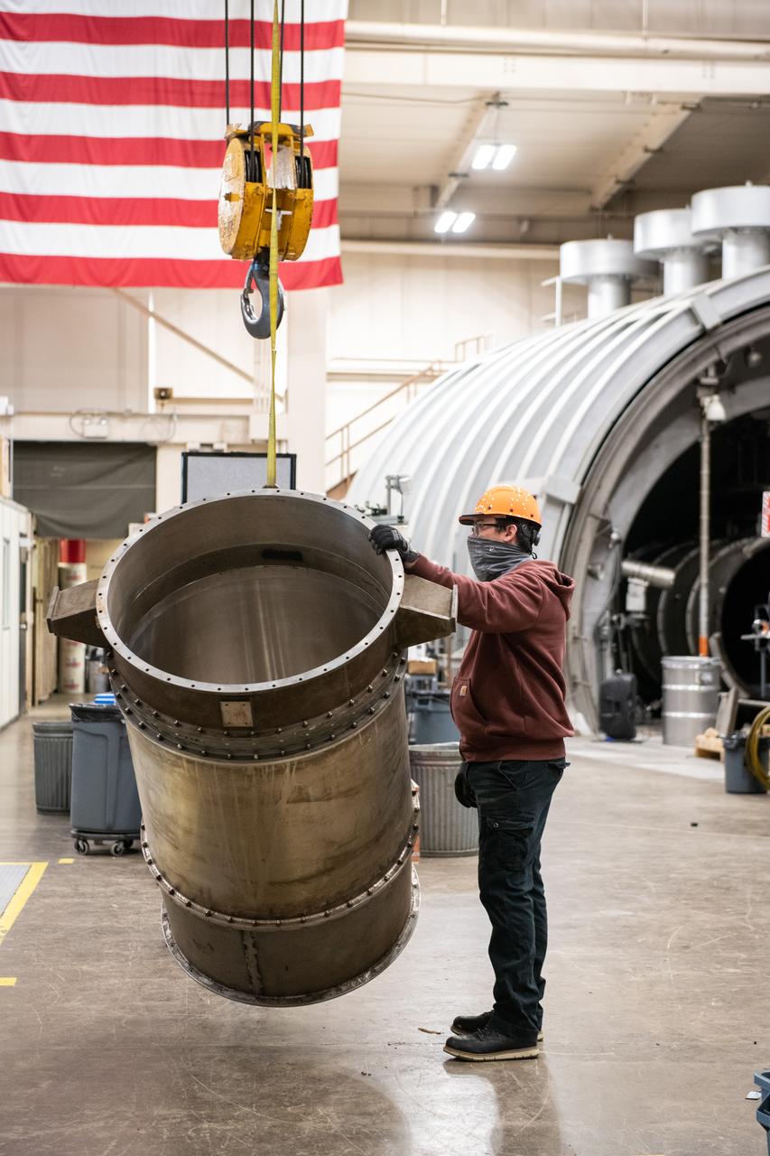
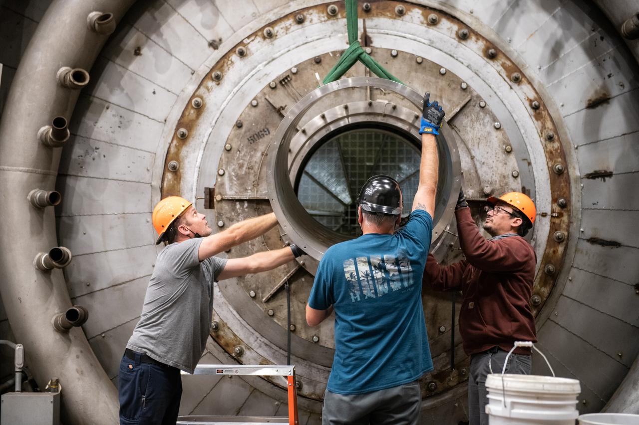
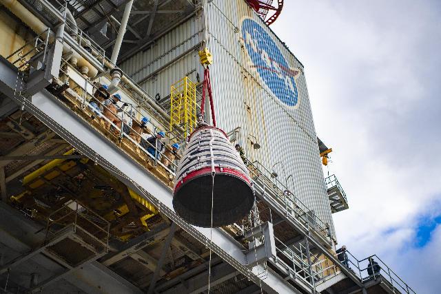
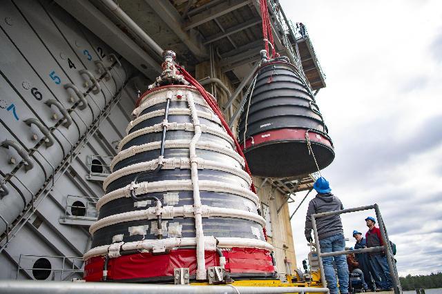
At Vandenberg Air Force Base in California, the aft stub adapter (ASA) and nozzle for a United Launch Alliance Atlas V rocket is removed from its shipping container. The launch vehicle will send NASA's Interior Exploration using Seismic Investigations, Geodesy and Heat Transport, or InSight, spacecraft to land on Mars. InSight is the first mission to explore the Red Planet's deep interior. It will investigate processes that shaped the rocky planets of the inner solar system including Earth. Liftoff from Vandenberg is scheduled for May 5, 2018.
American Society of Mechanical Engineers, ASME Nozzle Test at Propulsion Systems Laboratory, PSL Documentation Photographs
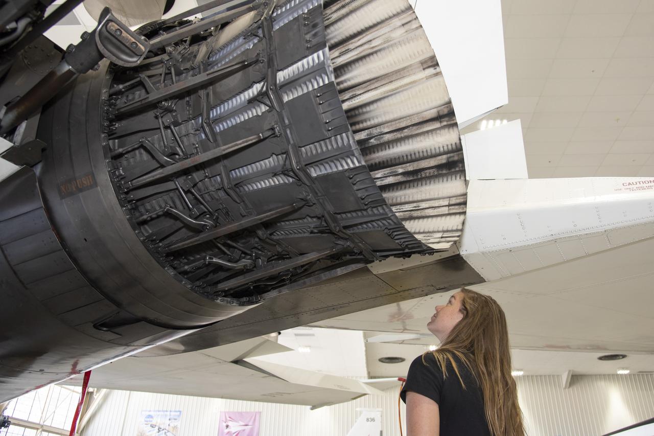
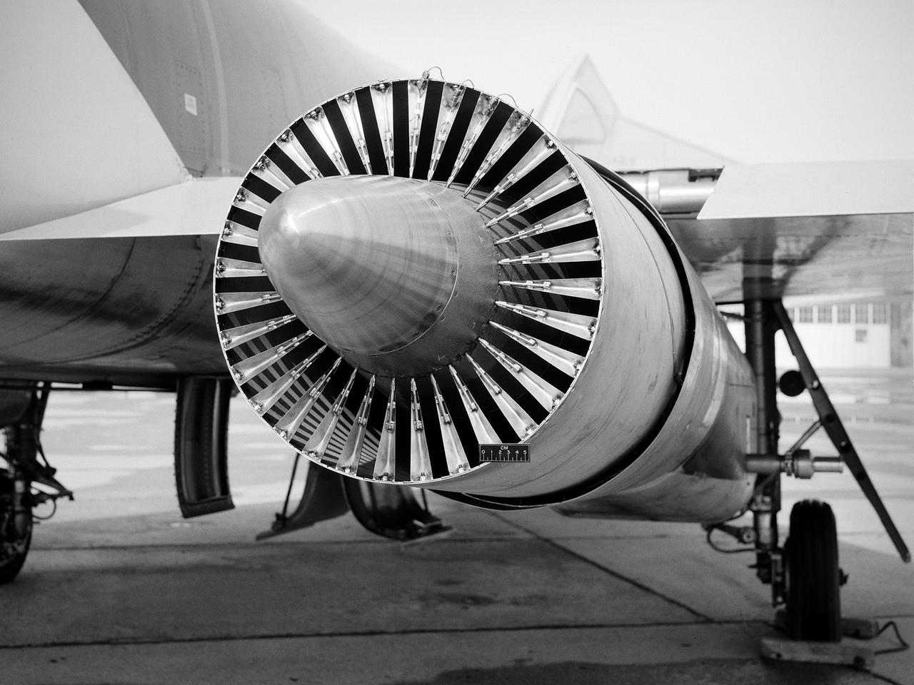
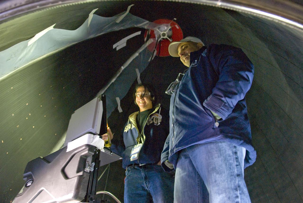
NASA’s 2017 astronaut candidates toured aircraft hangar at Armstrong Flight Research Center, in Southern California where Jenni Sidey-Gibbons looks inside engine nozzle of F-15 jet. The F-15 will fly in tandem with the X-59 QueSST during early flight test stages for the X-59 development.

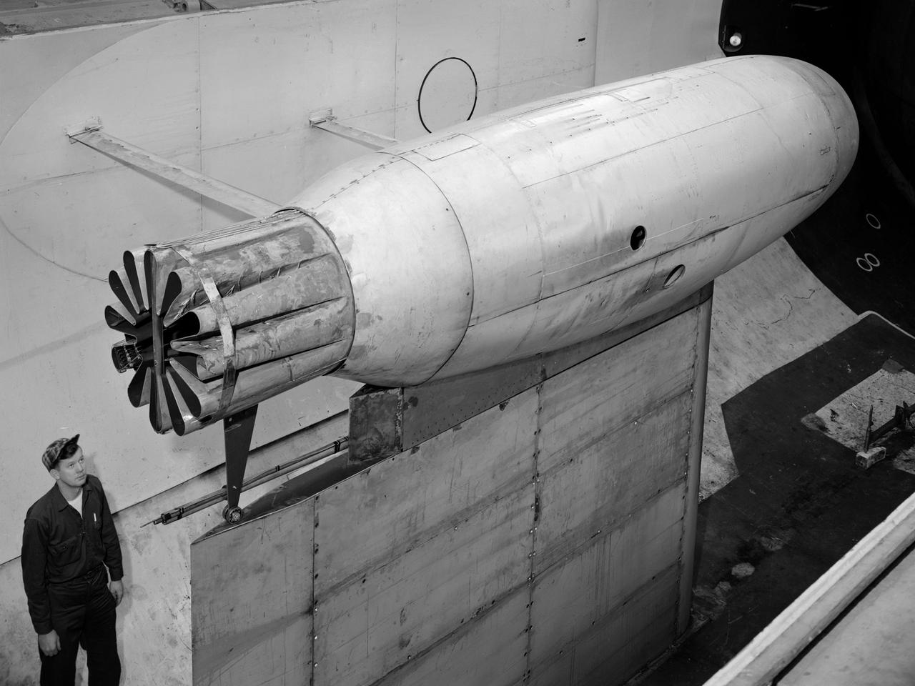
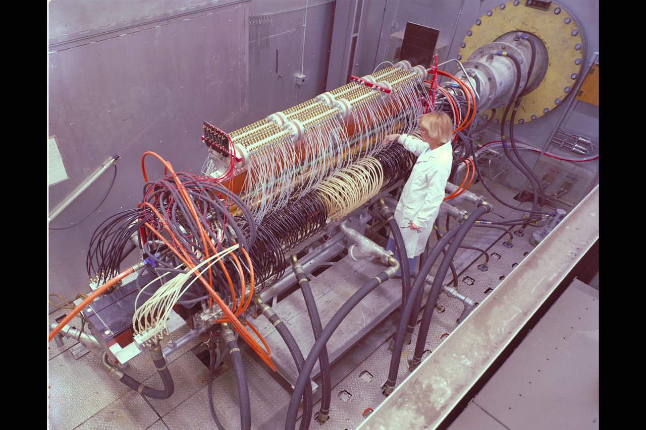
A Republic F-84 Thunderjet dramatically modified at the NASA Lewis Research Center to investigate the use of slotted nozzles to reduce exhaust noise. The F-84 was a single-seat fighter-bomber powered by an Allison J35 turbojet. It was the Air Force’s first post-World War II tactical aircraft and was used extensively in the Korean War. The laboratory had acquired the aircraft in 1954 and modified it in order to demonstrate the reverse thruster. The tail end of the aircraft was then removed for a series of large nozzle investigations. Lewis researchers launched an extensive program in the mid-1950s to develop methods of reducing engine noise as the airline industry was preparing to introduce the first turbojet-powered passenger aircraft. The early NACA investigations determined that the primary source of noise was the mixing of the engine’s hot exhaust with the cool surrounding air. Lewis researchers studied many different nozzles designed to facilitate this mixing. Nozzles with elongated exit sections, as seen in this photograph, produced lower noise levels. These long slot nozzles were also considered for Short Take-off and Landing aircraft because their long flat surfaces provided lift. In 1958 Lewis tested several full-scale slot nozzles on the F-84. The researchers, led by Willard Cole, sought to determine the noise-generation characteristics for nozzles having large a width-to-height ratio. The nozzle in this photograph has a 100 to 1 width-to-height ratio. Cole determined that the experimental nozzles produced the same levels of sound as the standard nozzle, but the changes in the directional noise were substantial.
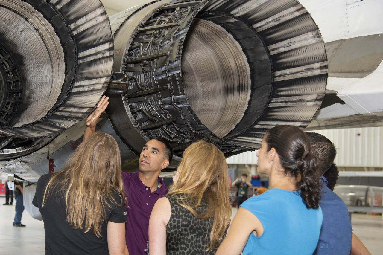
NASA's 2017 astronaut candidates toured aircraft hangar at Armstrong Flight Research Center, in Southern California (L to R) Jenni Sidey-Gibbons, Raja Chari, Loral O'Hara, Jasmin Moghbeli, Jonny Kim and Jessica Watkins look inside the engine nozzle of an F-15 jet. The F-15 will fly in tandem with the X-59 QueSST during early flight test stages for the X-59 development.
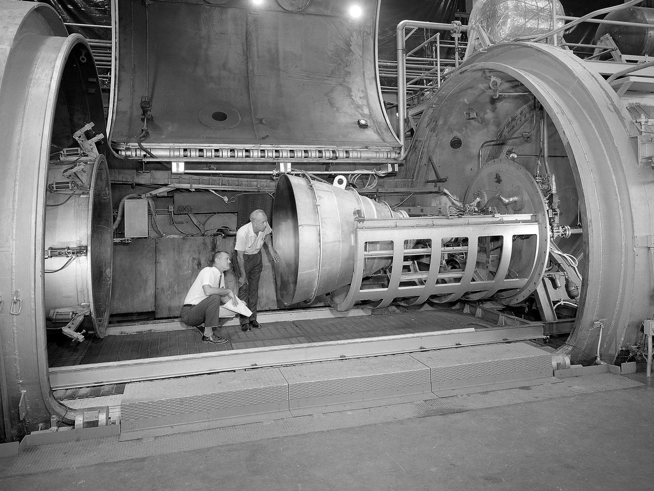
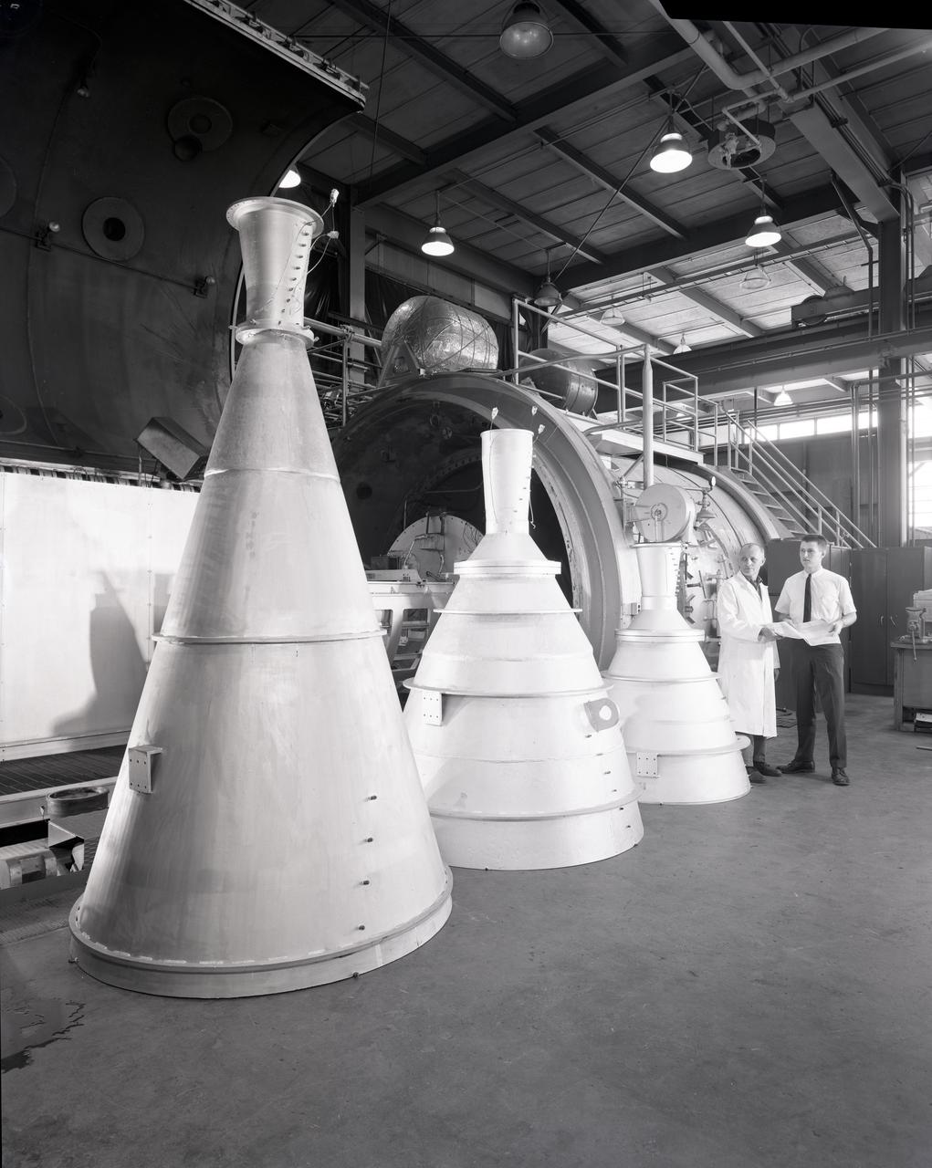
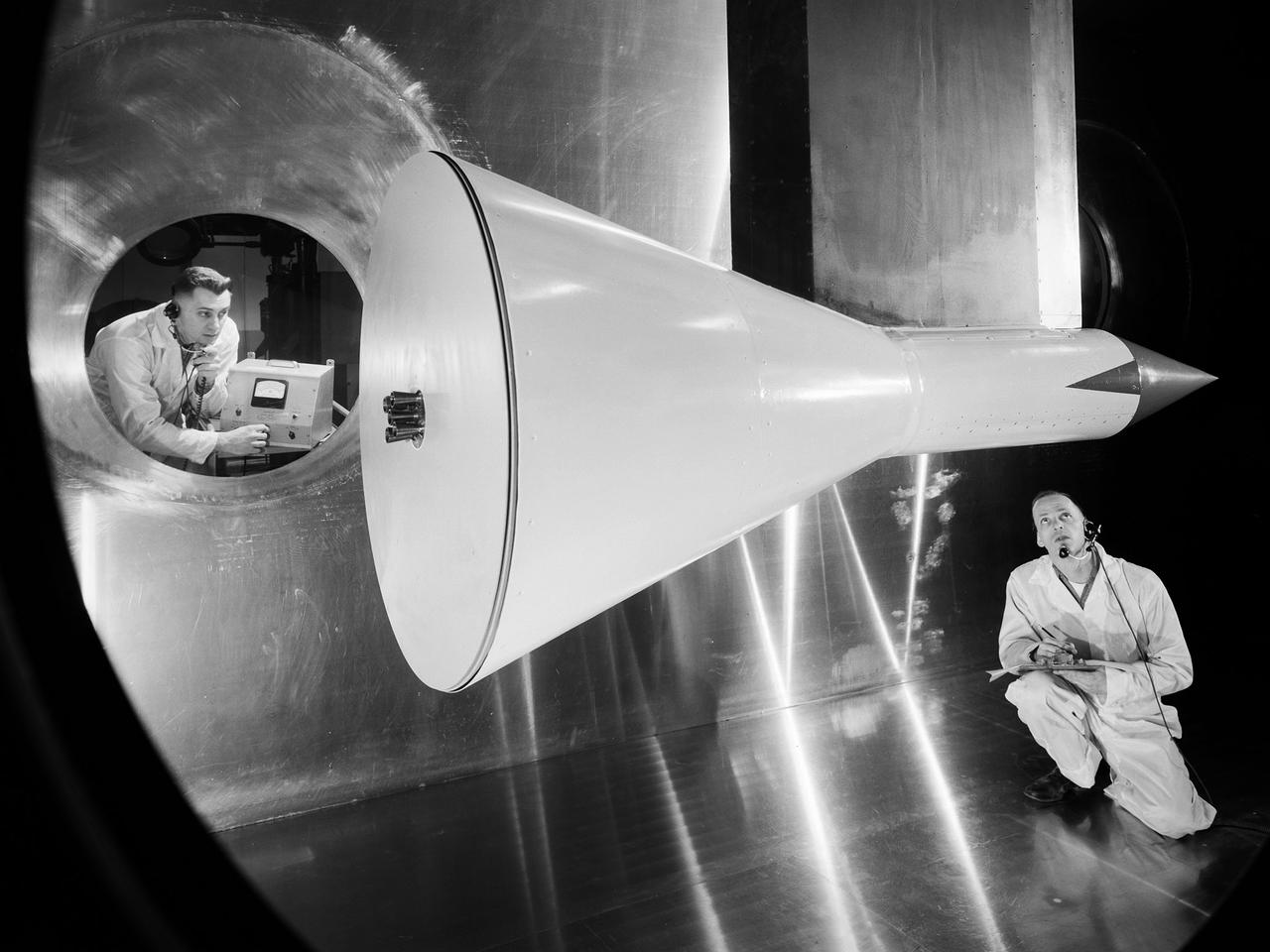
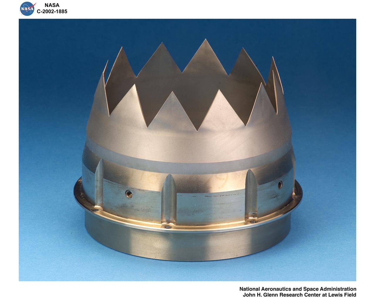
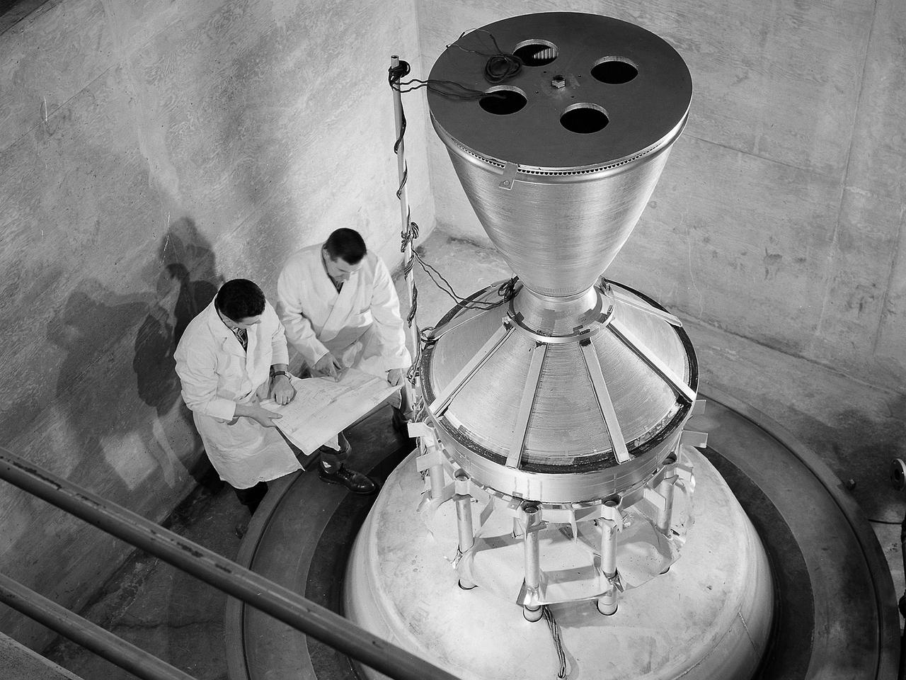
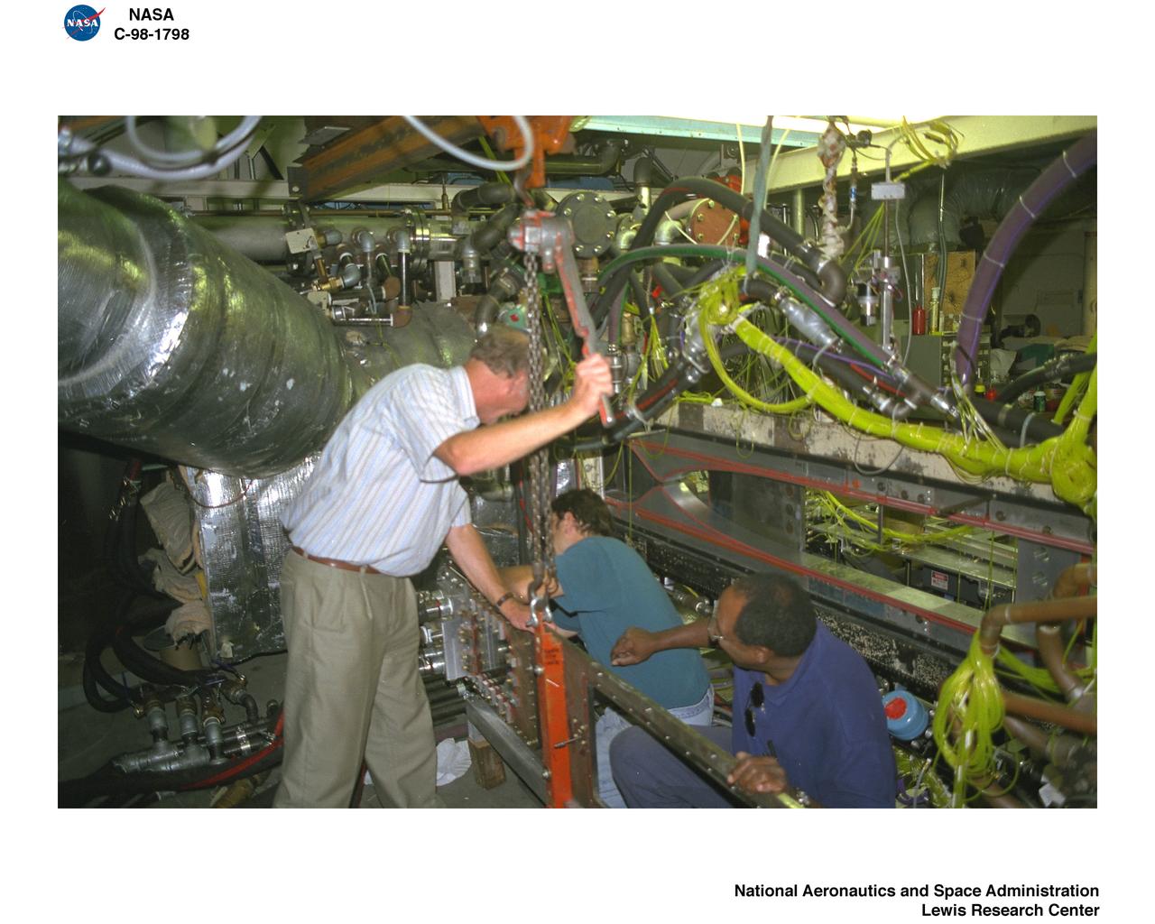
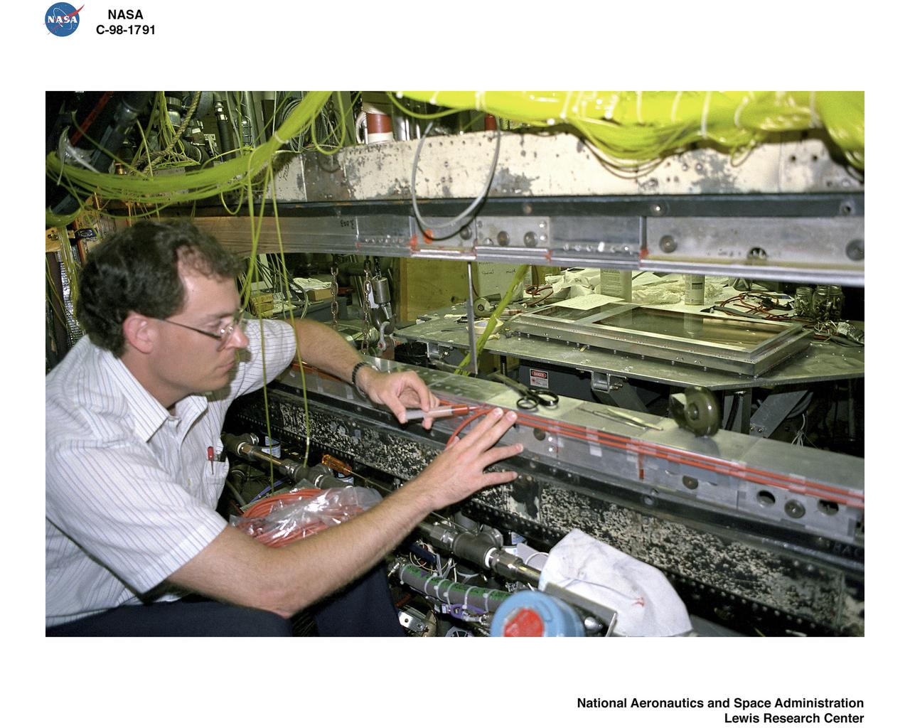
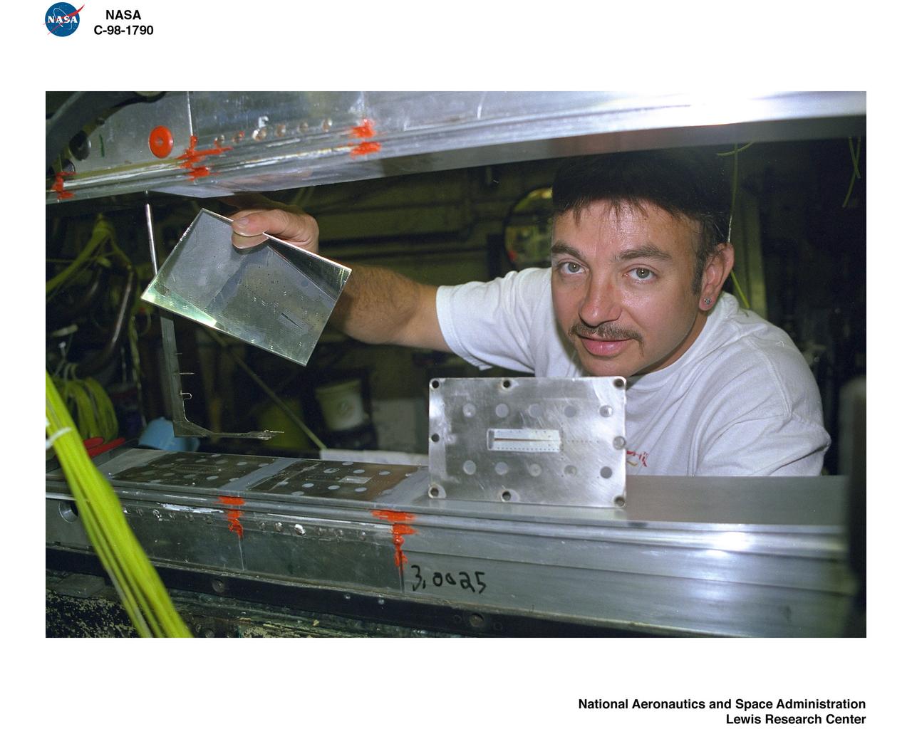
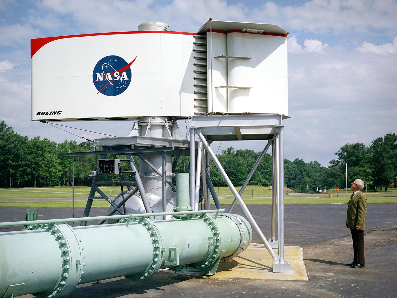
Bill Harrison and Bud Meilander check the setup of an Apollo Contour rocket nozzle in the Propulsion Systems Laboratory at the National Aeronautics and Space Administration (NASA) Lewis Research Center. The Propulsion Systems Laboratory contained two 14-foot diameter test chambers that could simulate conditions found at very high altitudes. The facility was used in the 1960s to study complex rocket engines such as the Pratt and Whitney RL-10 and rocket components such as the Apollo Contour nozzle, seen here. Meilander oversaw the facility’s mechanics and the installation of test articles into the chambers. Harrison was head of the Supersonic Tunnels Branch in the Test Installations Division. Researchers sought to determine the impulse value of the storable propellant mix, classify and improve the internal engine performance, and compare the results with analytical tools. A special setup was installed in the chamber that included a device to measure the thrust load and a calibration stand. Both cylindrical and conical combustion chambers were examined with the conical large area ratio nozzles. In addition, two contour nozzles were tested, one based on the Apollo Service Propulsion System and the other on the Air Force’s Titan transtage engine. Three types of injectors were investigated, including a Lewis-designed model that produced 98-percent efficiency. It was determined that combustion instability did not affect the nozzle performance. Although much valuable information was obtained during the tests, attempts to improve the engine performance were not successful.
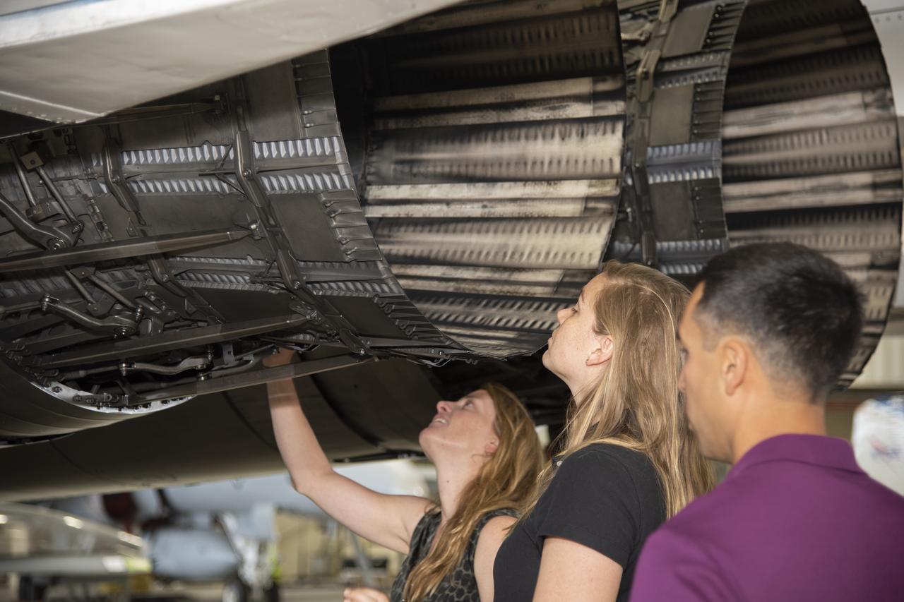
NASA's 2017 astronaut candidates toured aircraft hangar at Armstrong Flight Research Center, in Southern California where (L to R) Loral O'Hara, Jenni Sidey-Gibbons and Raja Chari look inside the engine nozzle of an F-15 jet. The F-15 will fly in tandem with the X-59 QueSST during early flight test stages for the X-59 development.
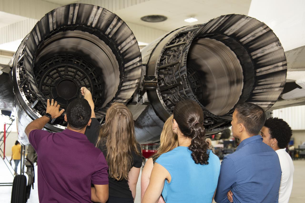
NASA's 2017 astronaut candidates toured aircraft hangar at Armstrong Flight Research Center, in Southern California (L to R) Raja Chari, Jenni Sidey-Gibbons, Loral O'Hara, Jasmin Moghbeli, Jonny Kim and Jessica Watkins look inside the engine nozzle of an F-15 jet. The F-15 will fly in tandem with the X-59 QueSST during early flight test stages for the X-59 development.
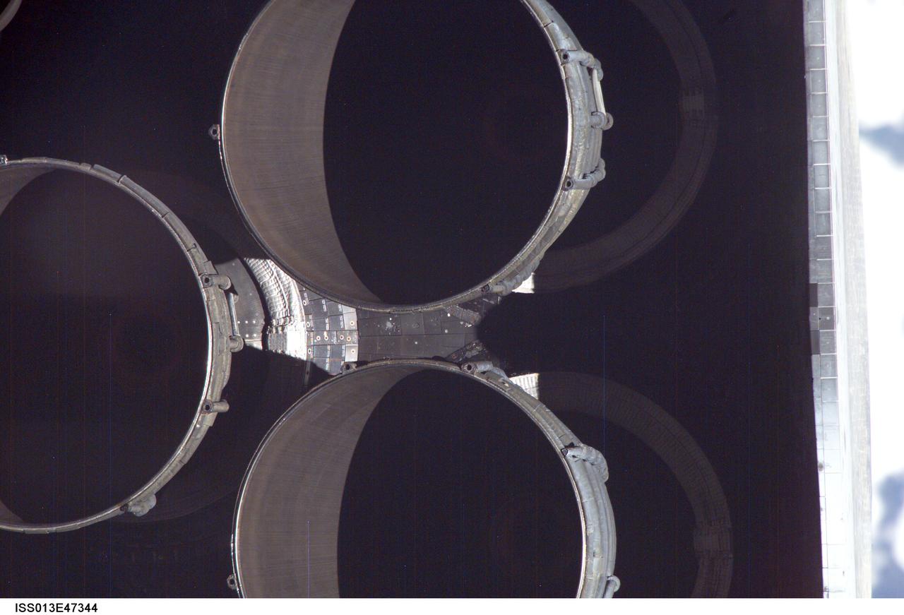
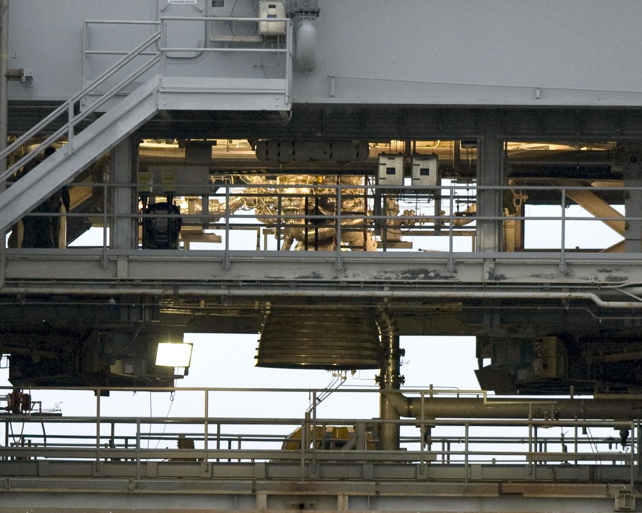
The nozzles for Discovery's three main engines are visible in this close-up image photographed by one of the Expedition 13 crew members onboard the International Space Station (ISS) during the STS-121 Rotating Pitch Maneuver (RPM) survey prior to docking of the two spacecraft. The Marshall Space Flight Center (MSFC) has management responsibility for development of the space shuttle main engines (SSME).
A Pratt and Whitney J57 engine is tested with a Greatex No.1 nozzle in the Altitude Wind Tunnel at the National Advisory Committee for Aeronautics (NACA) Lewis Flight Propulsion Laboratory. At the time the aircraft industry was preparing to introduce jet airliners to the nation’s airways. The noise produced by the large jet engines, however, posed a considerable problem for communities near airports. The NACA had formed a Special Subcommittee on Aircraft Noise to coordinate research on the issue. Preliminary tests showed that the source of the loudest noise was not the engine itself, but the mixing of the engine’s exhaust with the surrounding air in the atmosphere. The pressures resulting from this turbulence produced sound waves. Lewis researchers undertook a variety of noise-reduction studies involving engine design, throttling procedures, and noise suppressors. One of their first efforts focused on new types of nozzles to mix the exhaust with the surrounding air. The nozzles had a variety of shapes designed to slow down exhaust velocity before it combined with the air and thus decrease the noise. From January to May 1957 a Pratt and Whitney J57 engine was equipped with various shaped nozzles, as seen in this photograph, and run in simulated flight conditions in the Altitude Wind Tunnel. A number of nozzle configurations, including several multi-exit “organ pipe” designs, were created. It was found that the various nozzle types did reduce the noise levels, but they also reduced the aircraft’s thrust.
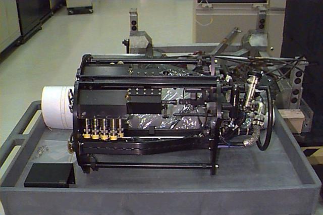
Researchers check the setup of a multi-nozzle base flow model in the 10- by 10-Foot Supersonic Wind Tunnel at the National Aeronautics and Space Administration (NASA) Lewis Research Center. NASA researchers were struggling to understand the complex flow phenomena resulting from the use of multiple rocket engines. Robert Wasko and Theodore Cover of the Advanced Development and Evaluation Division’s analysis and operations sections conducted a set of tests in the 10- by 10 tunnel to further understand the flow issues. The Lewis researchers studied four and five-nozzle configurations in the 10- by 10 at simulated altitudes from 60,000 to 200,000 feet. The nozzles were gimbaled during some of the test runs to simulate steering. The flow field for the four-nozzle clusters was surveyed in the center and the lateral areas between the nozzles, whereas the five-nozzle cluster was surveyed in the lateral area only.
National Aeronautics and Space Administration (NASA) Convair F-106B Delta Dart with a 32-spoke nozzle installed on its General Electric J85 test engine. Lewis acquired a Delta Dart fighter in 1966 to study the components for propulsion systems that could be applied to supersonic transport aircraft at transonic speeds. The F-106B was modified with two General Electric J85-13 engines under its wings to study these components. The original test plan was expanded to include the study of boattail drag, noise reduction, and inlets. From February to July 1971 the modified F-106B was used to study different ejector nozzles. Researchers conducted both acoustic and aerodynamic tests on the ground and in flight. Several models were created to test different suppression methods. NASA Lewis’ conical nozzle was used as the baseline configuration. Flightline and sideline microphones were set up on the ground. The F-106B would idle its own engine and buzz the recording station from an altitude of 300 feet at Mach 0.4 with the test engines firing. Researchers found that the suppression of the perceived noise level was usually lower during flight than the researchers had statistically predicted. The 64 and 32-spoke nozzles performed well in actual flight, but the others nozzles tended to negatively affect the engine’s performance. Different speeds or angles- -of-attack sometimes changed the noise levels. In the end, no general conclusions could be applied to all the nozzles.
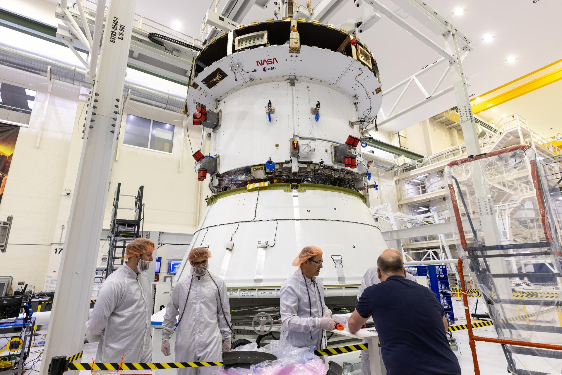
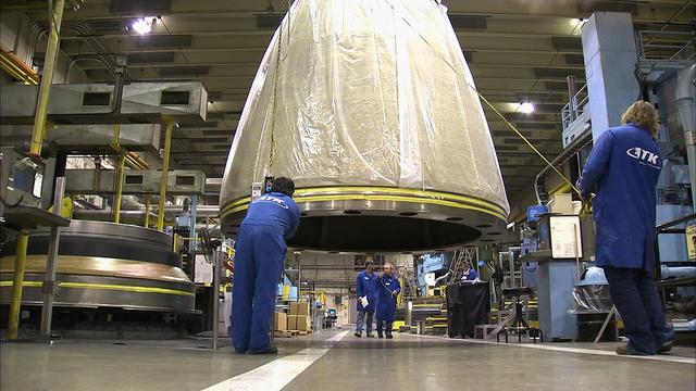
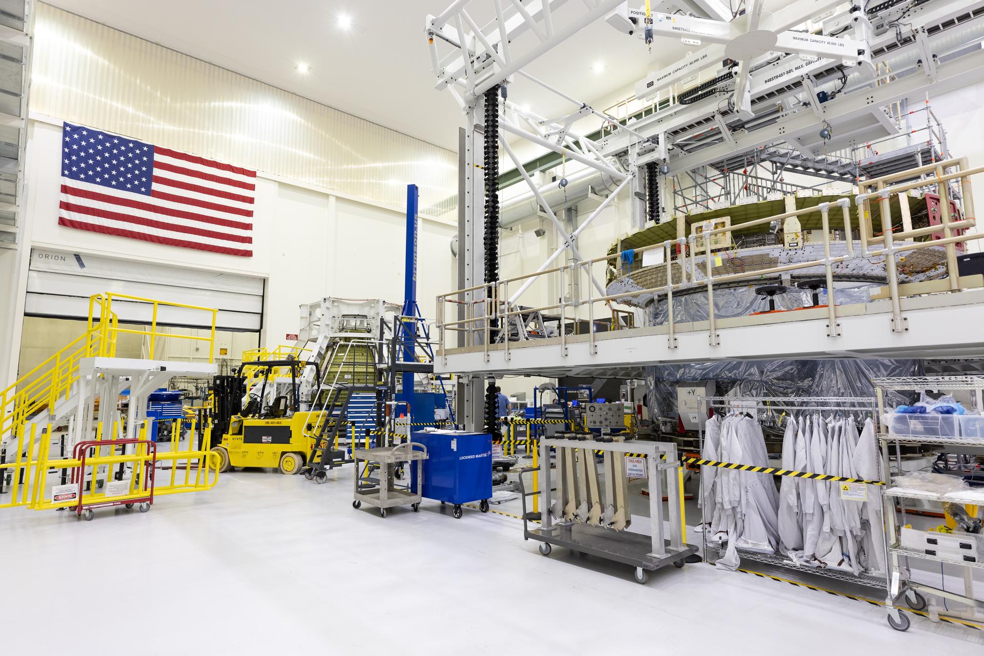
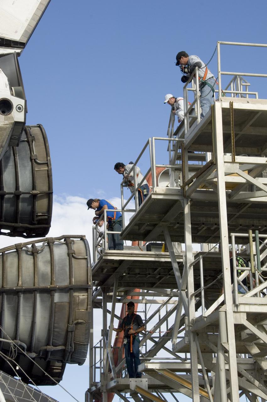
Teams prepare for the installation of the engine nozzle onto the European Service Module for NASA’s Artemis III mission on Tuesday, Feb. 17, 2026, inside the high bay of the Neil A. Armstrong Operations and Checkout Building at NASA’s Kennedy Space Center in Florida. The service module provides the Orion spacecraft’s propulsion, thermal control, electrical power, and life support systems during the Artemis III mission to send humans to explore the lunar South Pole region.

S121-E-05138 (4 July 2006) --- This ice, floating freely several yards from Discovery, is believed to have come from the orbiter's main engine nozzles and was photographed by the STS-121 crew shortly after the spacecraft reached orbit on July 4. The presence of similar ice has been seen on previous missions and is a normal occurrence.
Teams prepare for the installation of the engine nozzle onto the European Service Module for NASA’s Artemis III mission on Tuesday, Feb. 17, 2026, inside the high bay of the Neil A. Armstrong Operations and Checkout Building at NASA’s Kennedy Space Center in Florida. The service module provides the Orion spacecraft’s propulsion, thermal control, electrical power, and life support systems during the Artemis III mission to send humans to explore the lunar South Pole region.
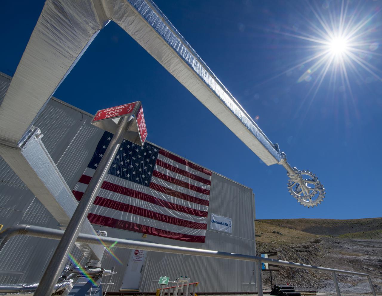
The quench system arm and nozzle are seen at the test area where the second and final qualification motor (QM-2) test for the Space Launch System’s booster will take place, Sunday, June 26, 2016, at Orbital ATK Propulsion Systems test facilities in Promontory, Utah. The test is scheduled for Tuesday, June 28 at 10:05 a.m. EDT (8:05 a.m. MDT). Photo Credit: (NASA/Bill Ingalls)
A closeup of one of the Cesaroni Technology, Inc. - constructed aerospike nozzles used in the Dryden Aerospike Rocket Test.
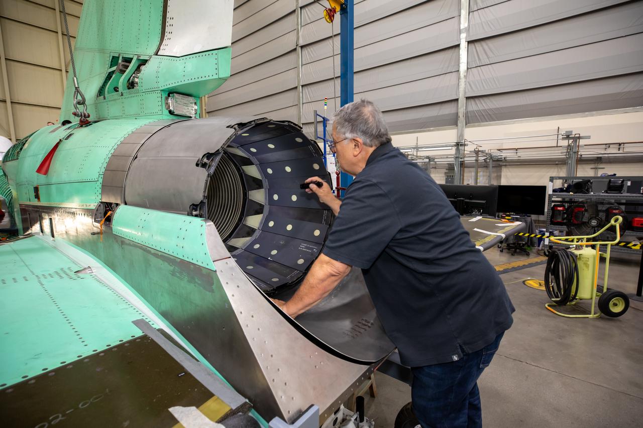
A quality inspector inspects the GE F-414 engine nozzle after installation at Lockheed Martin’s Skunk Works facility in Palmdale, California. Once the aircraft and ground testing are complete, the X-59 will undergo flight testing, which will demonstrate the plane’s ability to fly supersonic - faster than the speed of sound - while reducing the loud sonic boom. This could enable commercial supersonic air travel over land.
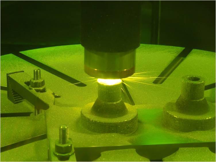
Scientists at NASA Jet Propulsion Laboratory make a rocket nozzle using a new 3-D printing technique that allows for multiple metallic properties in the same object.
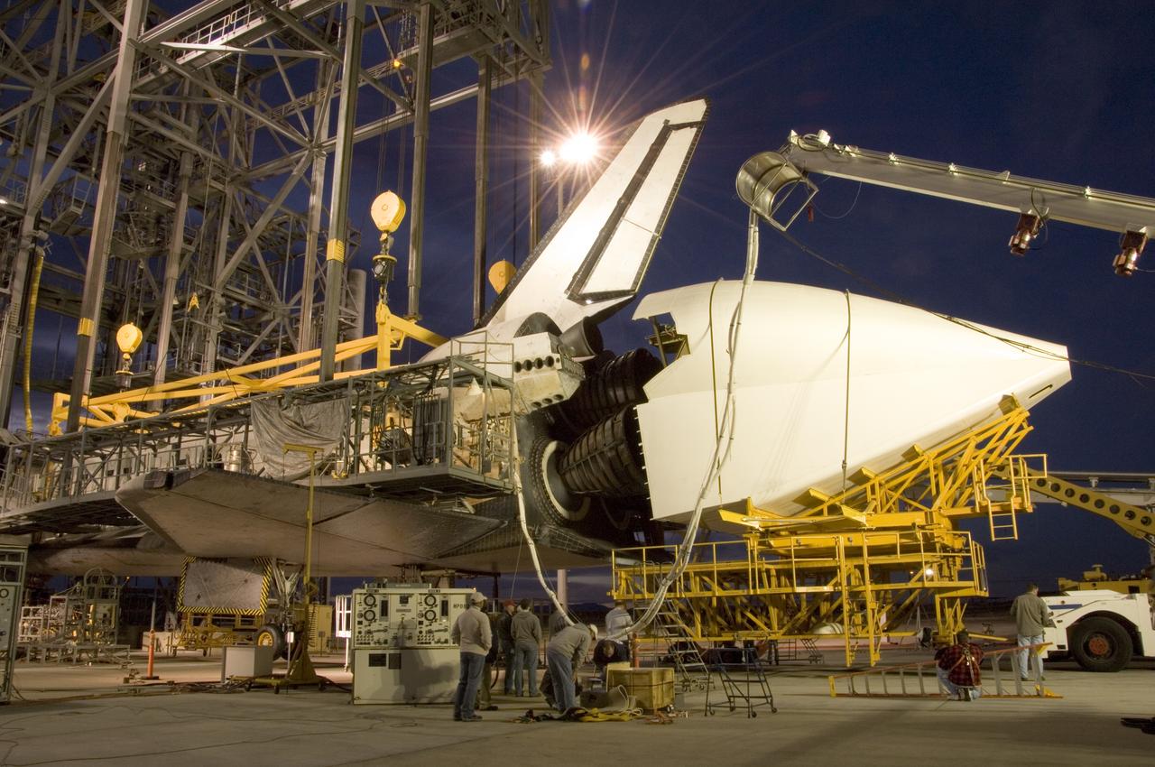
NASA technicians position the aerodynamic tailcone around the engine nozzles of the Space Shuttle Endeavour Dec. 7 in preparation for its ferry flight from NASA's Dryden Flight Research Center at Edwards Air Force Base back to the Kennedy Space Center in Florida.
VANDENBERG AIR FORCE BASE, Calif. – In the Horizontal Processing Facility at Space Launch Complex 2 on Vandenberg Air Force Base in California, the engine bell is installed around the second-stage nozzle of the Delta II rocket for NASA's Orbiting Carbon Observatory-2 mission, or OCO-2. OCO-2 is scheduled to launch aboard a United Launch Alliance Delta II rocket from Space Launch Complex 2 in July. The rocket's second stage will insert OCO-2 into a polar Earth orbit. OCO-2 will collect precise global measurements of carbon dioxide in the Earth's atmosphere and provide scientists with a better idea of the chemical compound's impacts on climate change. Scientists will analyze this data to improve our understanding of the natural processes and human activities that regulate the abundance and distribution of this important atmospheric gas. To learn more about OCO-2, visit http://oco.jpl.nasa.gov. Photo credit: NASA/Randy Beaudoin
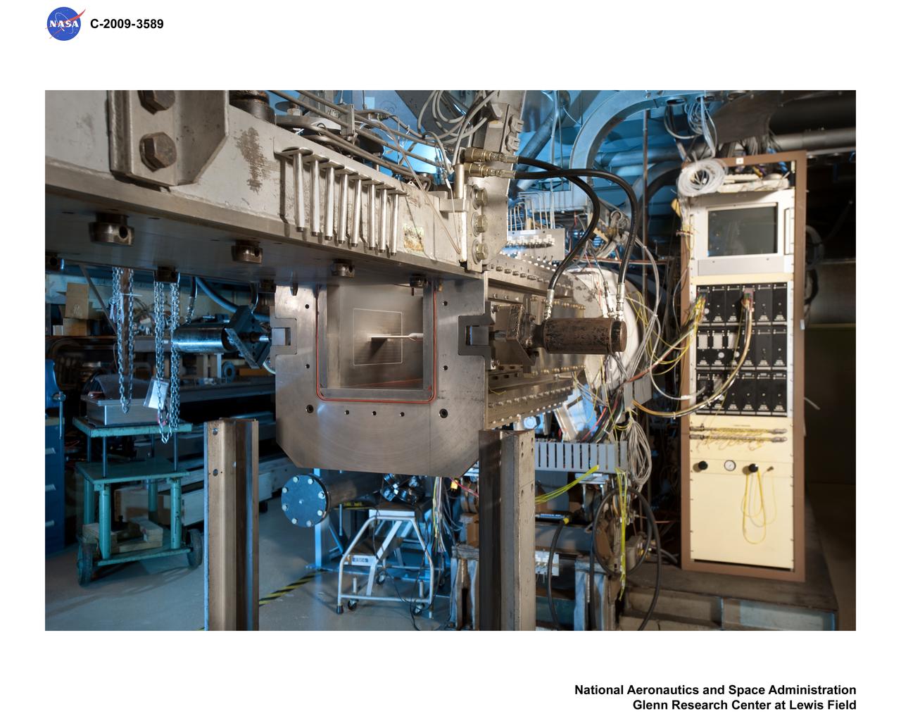
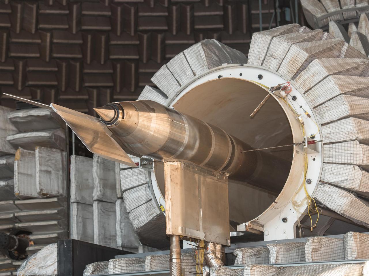
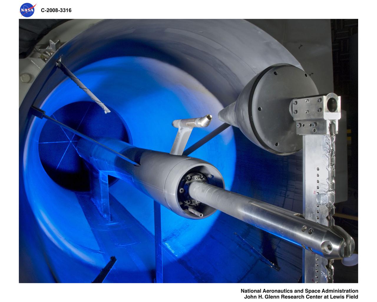
Low Boom GRC Advanced Nozzle Consepts, Exhaust Nozzle Plume Effects on Sonic Boom Hardware in 1x1 Supersonic Wind Tunnel
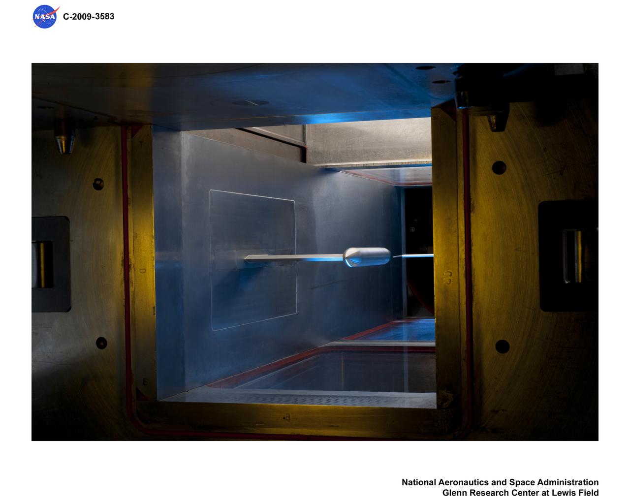
Low Boom GRC Advanced Nozzle Consepts, Exhaust Nozzle Plume Effects on Sonic Boom Hardware in 1x1 Supersonic Wind Tunnel
The new production nozzle is lifted on the Fred Haise Test Stand at NASA’s Stennis Space Center on Feb. 6. Crews used specially adapted procedures and tools to swap out the nozzles with the engine in place.
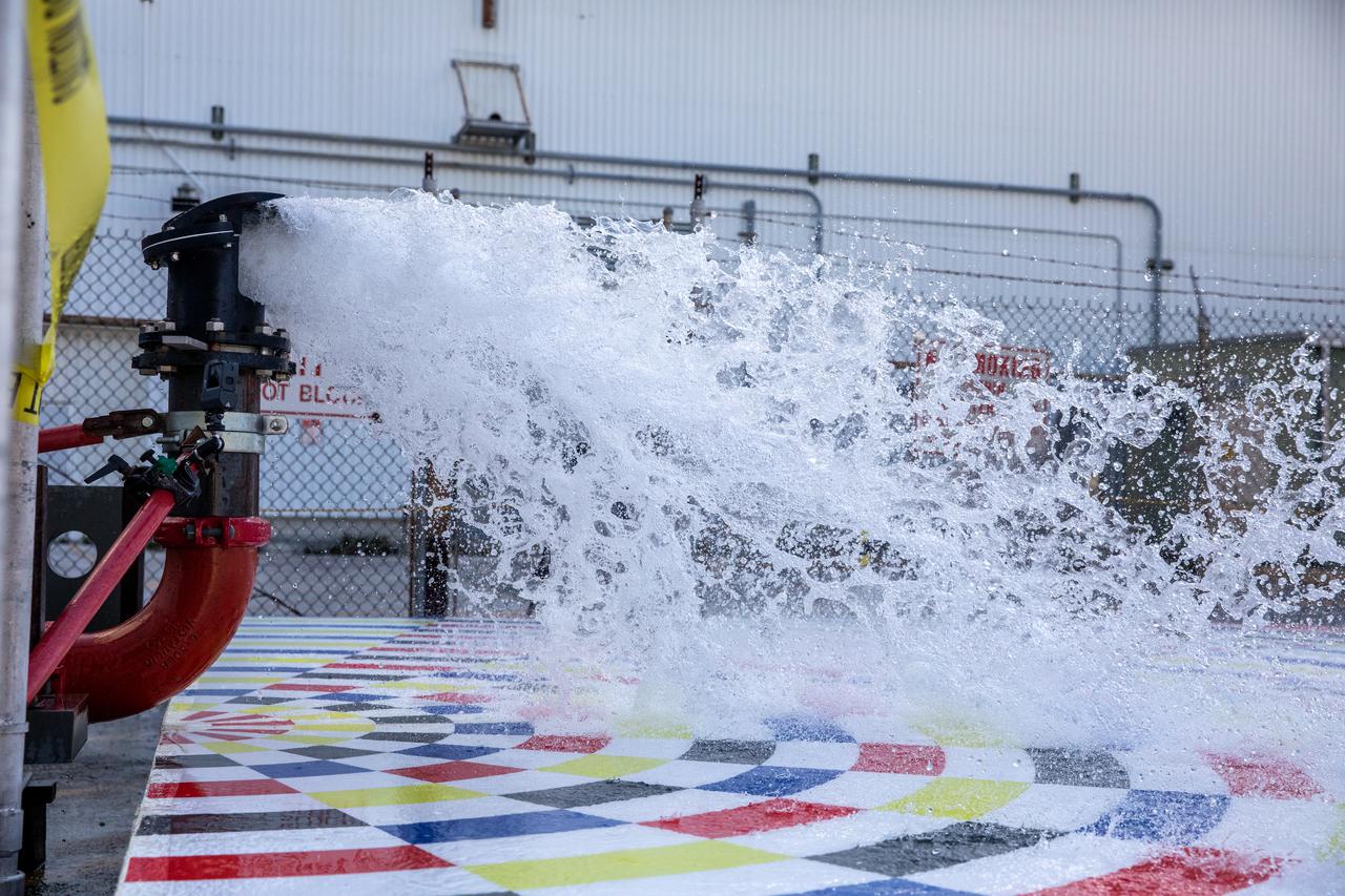
Water flows through a small-scale, 3D-printed nozzle during prototype testing of a new rainbird system on March 24, 2021, at NASA’s Kennedy Space Center in Florida. Rainbirds are large water nozzles located on the mobile launcher (ML) that release a high volume of water when the Space Launch System (SLS) rocket lifts off, protecting the vehicle, launch pad, and ML by absorbing some of the heat and energy generated during launch. The test involved running various water pressures through smaller nozzles to capture data that can be used to develop full-scale replacement nozzles for future missions under the Artemis program.
HISTORIC AERONAUTICS ARTIFACTS, CHEVRON NOZZLE

Air Breathing Propulsion - LEAR 12 CHEVRON NOZZLE
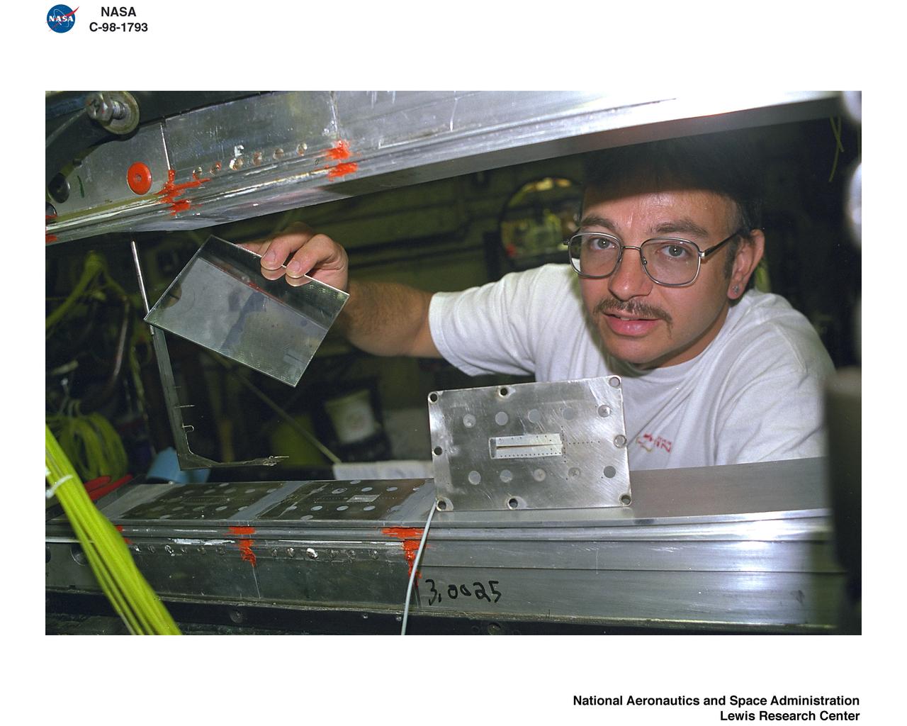
DUMMY SAMPLE FENCES AND WATER CODED SQUARE NOZZLE
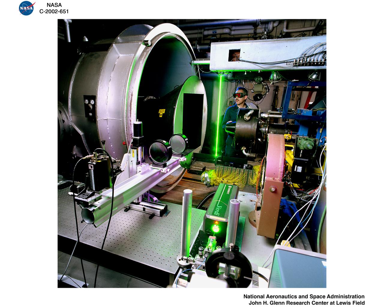
RAYLEIGH SCATTERING SET UP ON LARGE NOZZLE RIG
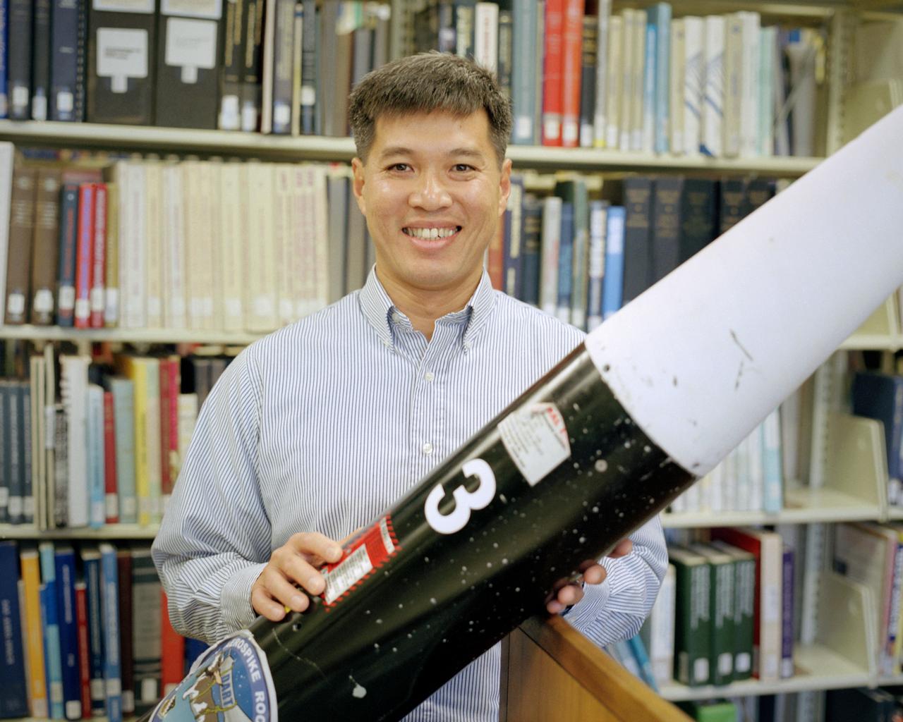
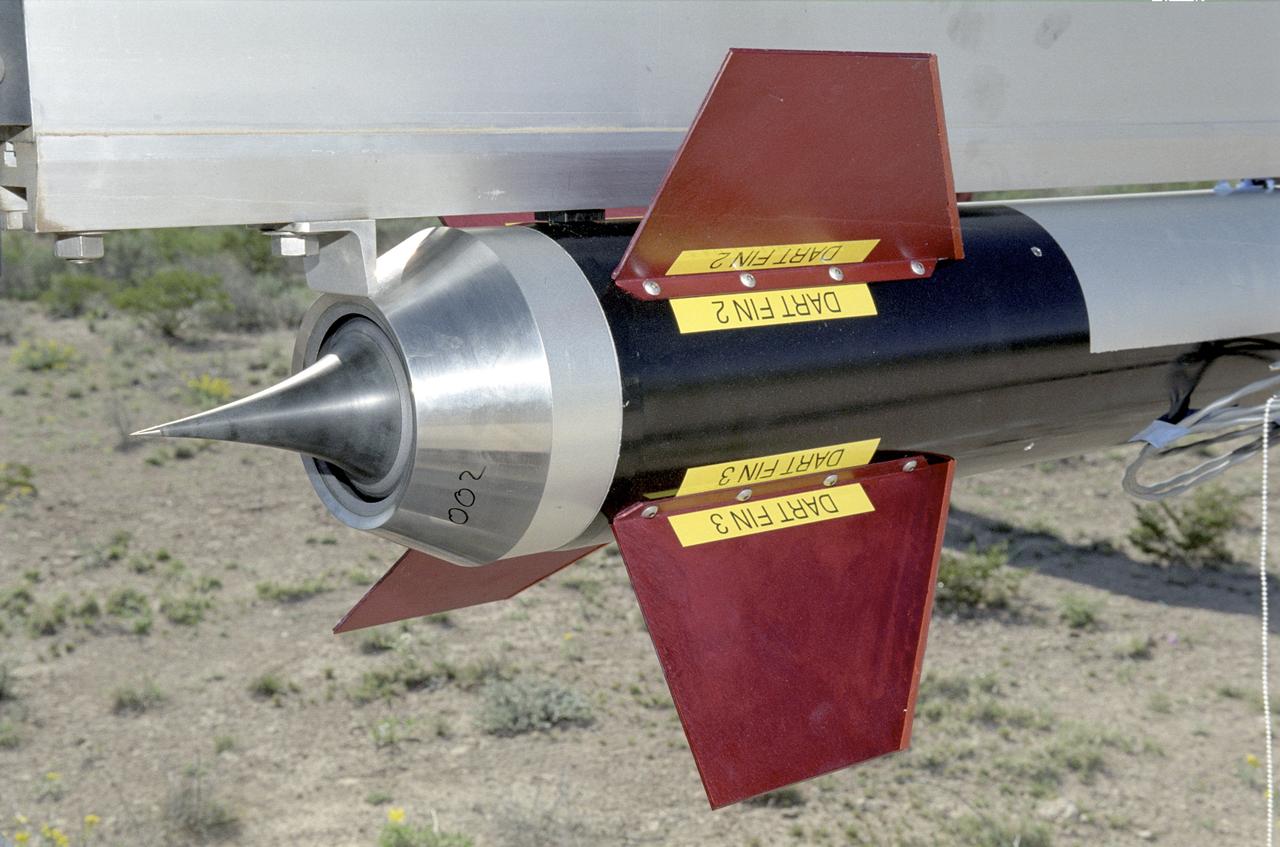
Trong Bui, NASA Dryden's principal investigator for the aerospike rocket tests, holds the first of two 10-ft. long rockets that were flown at speeds up to Mach 1.5, the first known supersonic tests of rockets with aerospike nozzles. The goals of the flight research project were to obtain aerospike rocket nozzle performance data in flight and to investigate the effects of transonic flow and transient flight conditions on aerospike nozzle performance.
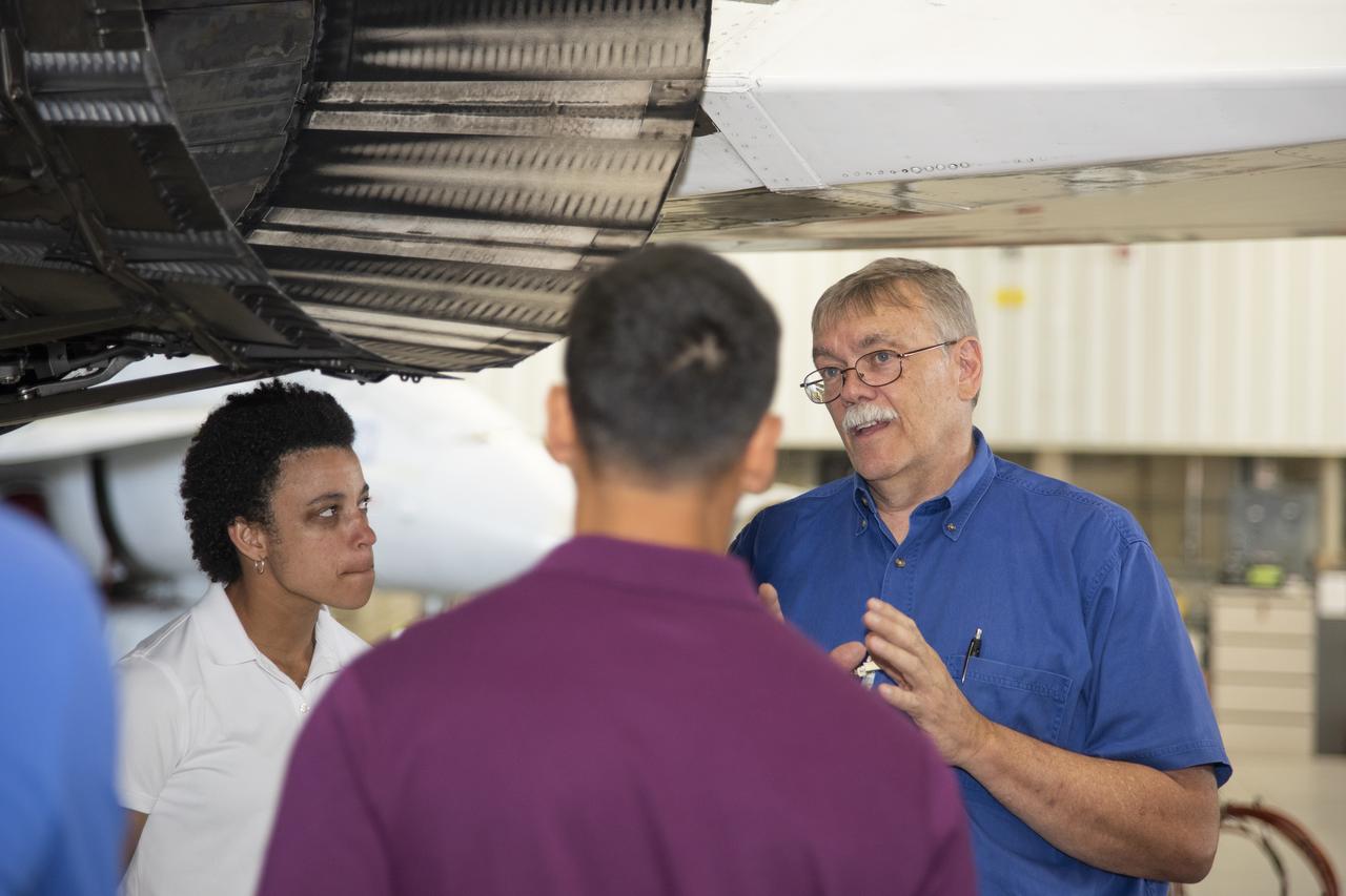
NASA's 2017 astronaut candidates toured aircraft hangar at Armstrong Flight Research Center, in Southern California where Crew Chief Tom Grindle talks with (L to R) Jessica Watkins and Raja Chari near engine nozzle of F-15 jet. The F-15 will fly in tandem with the X-59 QueSST during early flight test stages for the X-59 development.
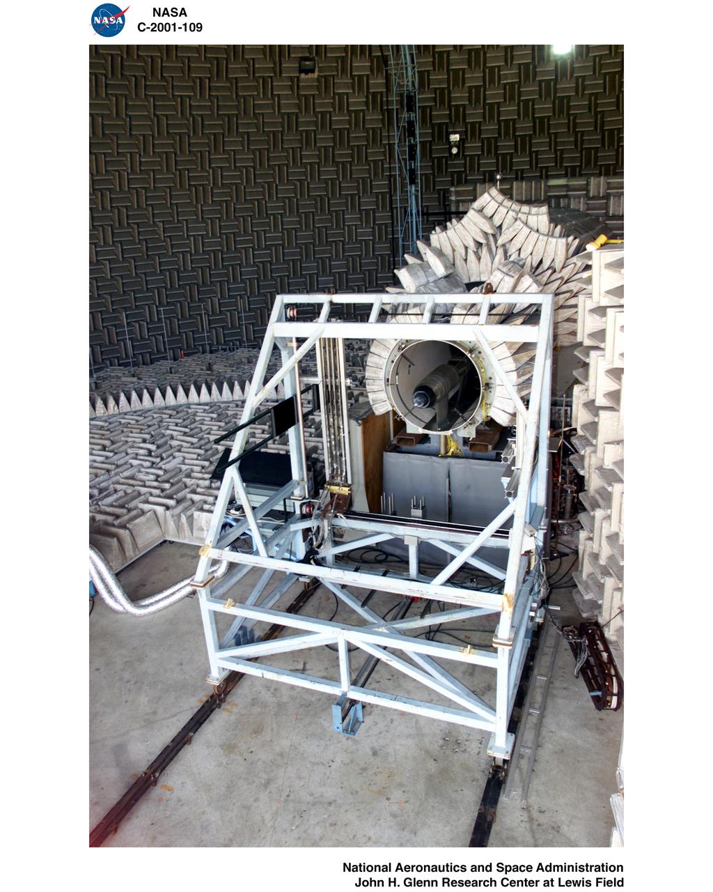
Nozzle Acoustic Test Rig (NATR), High Flow Jet Exit 2009
Twin Jet Hardware in the Nozzle Acoustical Test Rig, NATR
Nozzle Acoustic Test Rig (NATR), High Flow Jet Exit 2009
Nozzle Acoustic Test Rig (NATR), High Flow Jet Exit 2009
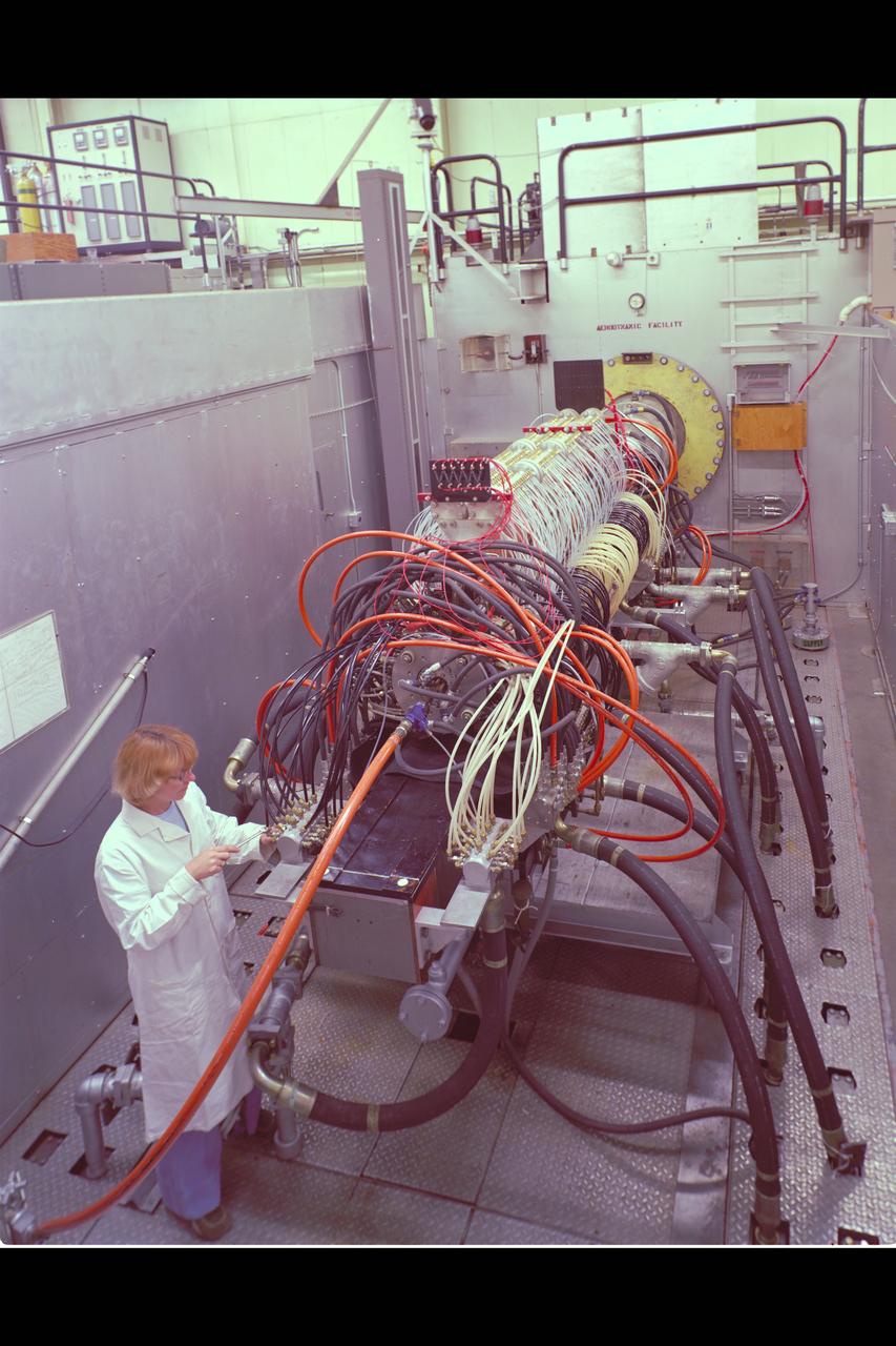
Technicians manufacture a nozzle for the Kiwi B-1-B nuclear rocket engine in the Fabrication Shop’s vacuum oven at the National Aeronautics and Space Administration (NASA) Lewis Research Center. The Nuclear Engine for Rocket Vehicle Applications (NERVA) was a joint NASA and Atomic Energy Commission (AEC) endeavor to develop a nuclear-powered rocket for both long-range missions to Mars and as a possible upper-stage for the Apollo Program. The early portion of the program consisted of basic reactor and fuel system research. This was followed by a series of Kiwi reactors built to test basic nuclear rocket principles in a non-flying nuclear engine. The next phase, NERVA, would create an entire flyable engine. The final phase of the program, called Reactor-In-Flight-Test, would be an actual launch test. The AEC was responsible for designing the nuclear reactor and overall engine. NASA Lewis was responsible for developing the liquid-hydrogen fuel system. The turbopump, which pumped the fuels from the storage tanks to the engine, was the primary tool for restarting the engine. The NERVA had to be able to restart in space on its own using a safe preprogrammed startup system. Lewis researchers endeavored to design and test this system. This non-nuclear Kiwi engine, seen here, was being prepared for tests at Lewis’ High Energy Rocket Engine Research Facility (B-1) located at Plum Brook Station. The tests were designed to start an unfueled Kiwi B-1-B reactor and its Aerojet Mark IX turbopump without any external power.
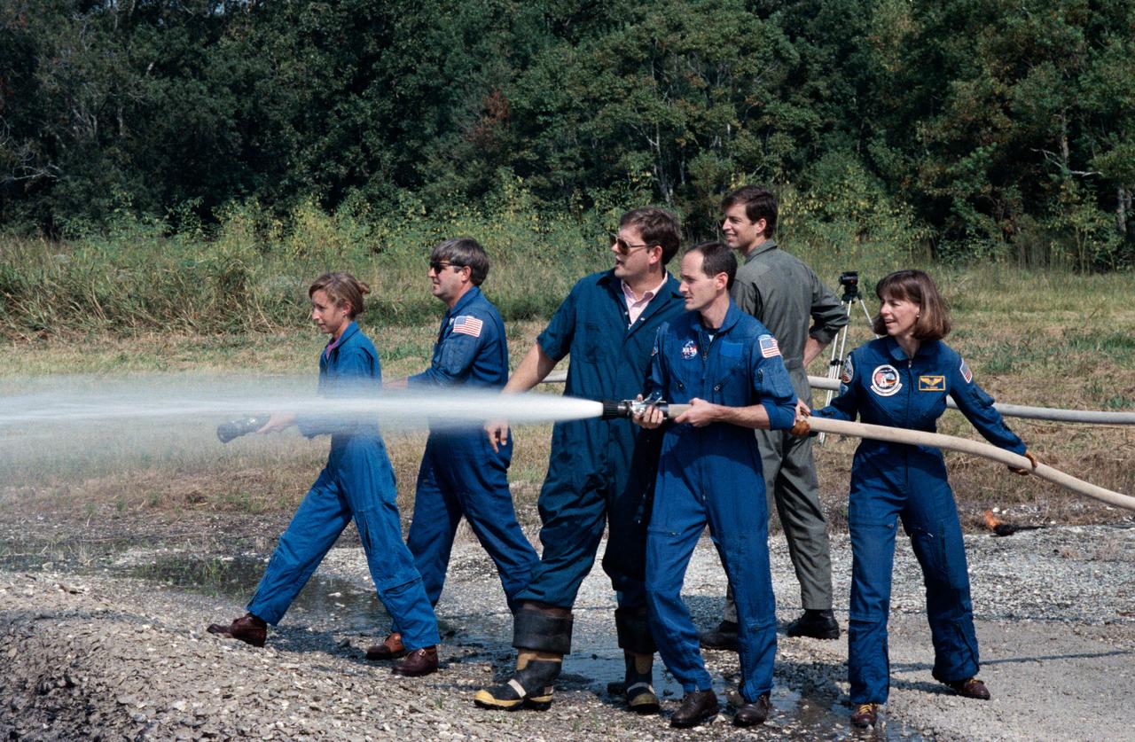
STS-32 crewmembers use water hoses during fire fighting exercises at JSC's Fire Training Pit across from the Gilruth Center Bldg 207. Mission Specialist (MS) G. David Low with nozzle open directs water into the fire as fire/ security personnel coaches and instructs him on his attempt to extinguish the blaze. MS Bonnie J. Dunbar maneuvers the hose behind Low. A second group of crewmembers alongside Low and Dunbar, MS Marsha S. Ivins, holding hose nozzle, Commander Daniel C. Brandenstein, and Pilot James D. Wetherbee position themselves before opening hose nozzle.
Twin Jet Model, Nozzle Acoustic Test Rig, NATR, Aeroacoustic Propulsion Laboratory, AAPL
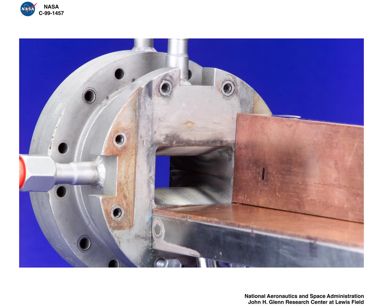
REASSEMBLY OF DUCT LAB SWT MACH 4-5 NOZZLE WITH MACH 2.0 INJECTION
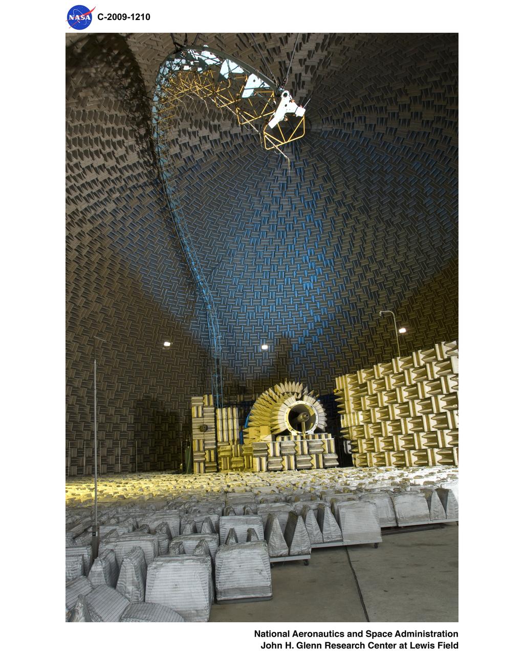
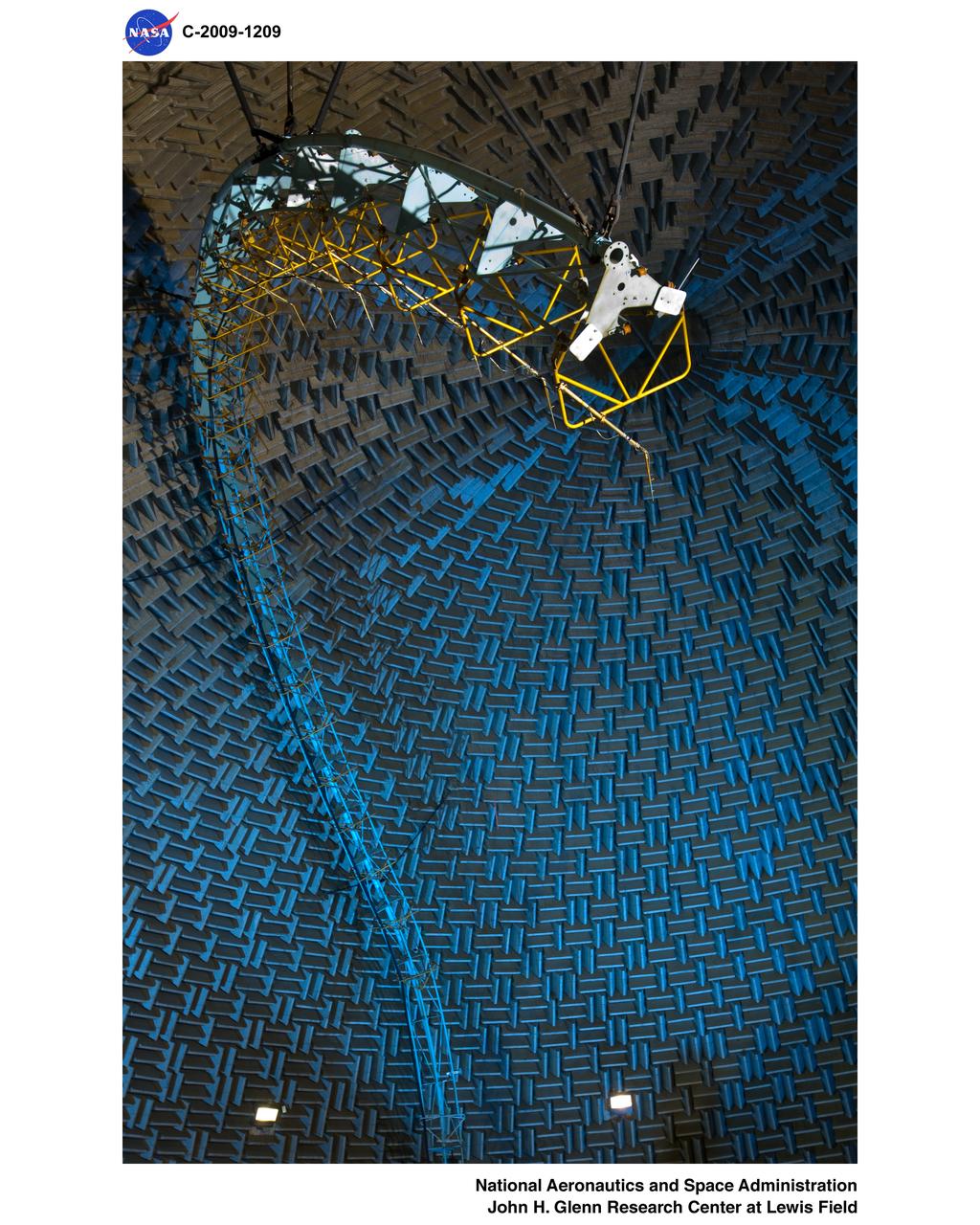
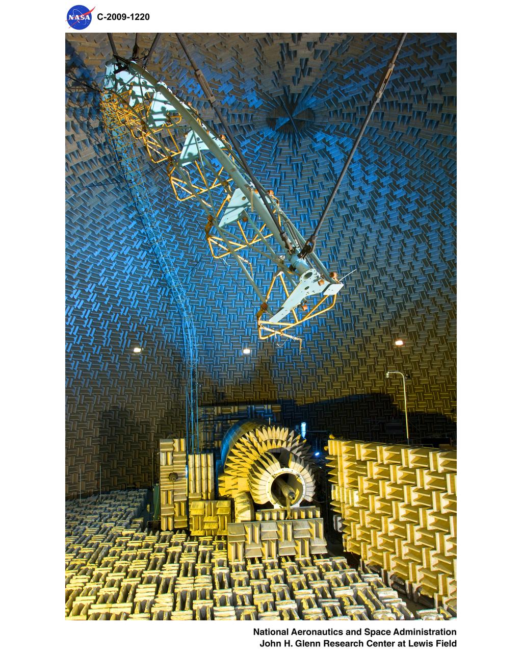
OVERHEAD VIEW OF NOZZLE ACOUSTIC TEST RIG POWERED LIFT RIG AND ACTIVE NOISE CONTROL FAN
REASSEMBLY OF DUCT LAB SWT MACH 4-5 NOZZLE WITH MACH 2.0 INJECTION

Twin Jet Model, Nozzle Acoustic Test Rig, NATR, Aeroacoustic Propulsion Laboratory, AAPL
REASSEMBLY OF DUCT LAB SWT MACH 4-5 NOZZLE WITH MACH 2.0 INJECTION
REASSEMBLY OF DUCT LAB SWT MACH 4-5 NOZZLE WITH MACH 2.0 INJECTION
3/4 view of the Nozzle of the Peregrine Rocket Motor, tested at the Outdoor Aerodynamic Research Facility (OARF, N-249). at Ames Research Center.
Noise Accoustical Test Rig (NATR) Crew Exploration Vehicle (CEV) 85-AA-Constellation, Orion Capsule and nozzle on front of NATR
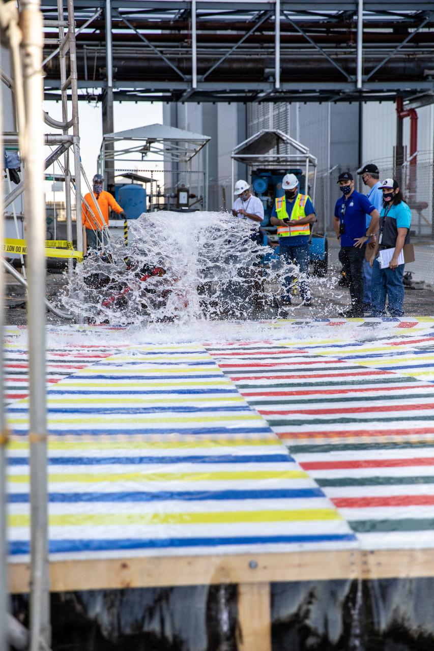
Teams with NASA’s Exploration Ground Systems and supporting contractors conduct prototype testing of a new rainbird system at the agency’s Kennedy Space Center in Florida on March 24, 2021, that can be used for the crewed Artemis II mission to the Moon. Rainbirds are large water nozzles located on the mobile launcher (ML) that release a high volume of water when the Space Launch System (SLS) rocket lifts off, protecting the vehicle, launch pad, and ML by absorbing some of the heat and energy generated during launch. The test involved running various water pressures through small-scale, 3D-printed nozzles to capture data that can be used to develop full-scale replacement nozzles for future missions under the Artemis program.

Alongside the iconic Vehicle Assembly Building at NASA’s Kennedy Space Center in Florida, teams with the agency’s Exploration Ground Systems and supporting contractors conduct prototype testing of a new rainbird system on March 24, 2021. Rainbirds are large water nozzles located on the mobile launcher (ML) that release a high volume of water when the Space Launch System (SLS) rocket lifts off, protecting the vehicle, launch pad, and ML by absorbing some of the heat and energy generated during launch. The test involved running various water pressures through small-scale, 3D-printed nozzles to capture data that can be used to develop full-scale replacement nozzles for future missions under the Artemis program.
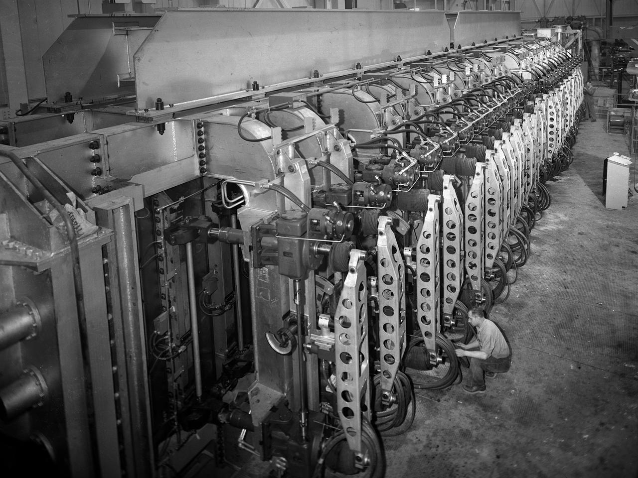
A mechanic checks the tubing on one of the many jacks which control the nozzle section of the 10- by 10-Foot Supersonic Wind Tunnel at the National Advisory Committee for Aeronautics (NACA) Lewis Flight Propulsion Laboratory. The 10- by 10-foot tunnel, which had its official opening in May 1956, was built under the Congressional Unitary Plan Act which coordinated wind tunnel construction at the NACA, Air Force, industry, and universities. The 10- by 10 was the largest of the three NACA tunnels built under the act. The 10- by 10 wind tunnel can be operated as a closed circuit for aerodynamic tests or as an open circuit for propulsion investigations. The 10-foot tall and 76-foot long stainless steel nozzle section just upstream from the test section can be adjusted to change the speed and composition of the air flow. Hydraulic jacks, seen in this photograph, flex the 1.37-inch thick walls of the tunnel nozzle. The size of the nozzle’s opening controls the velocity of the air through the test section. Seven General Electric motors capable of generating 25,000 horsepower produce the Mach 2.5 and 2.5 airflows. The facility was mostly operated at night due to its large power load requirements.
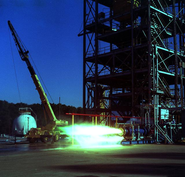
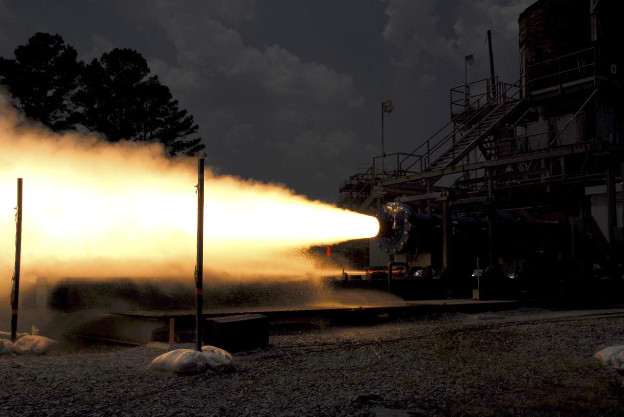
24 inch Hybrid motor test firing at Marshall's Test Stand 500. Liquid/gas are mixed with solid propellents to investigate materials, propellents, and nozzle stability characteristics.
Joel Perez (left) and Jay Labat, both of Pratt & Whitney Rocketdyne, are in close quarters as they check for leaks inside the nozzle of a space shuttle main engine mounted on the A-2 Test Stand.
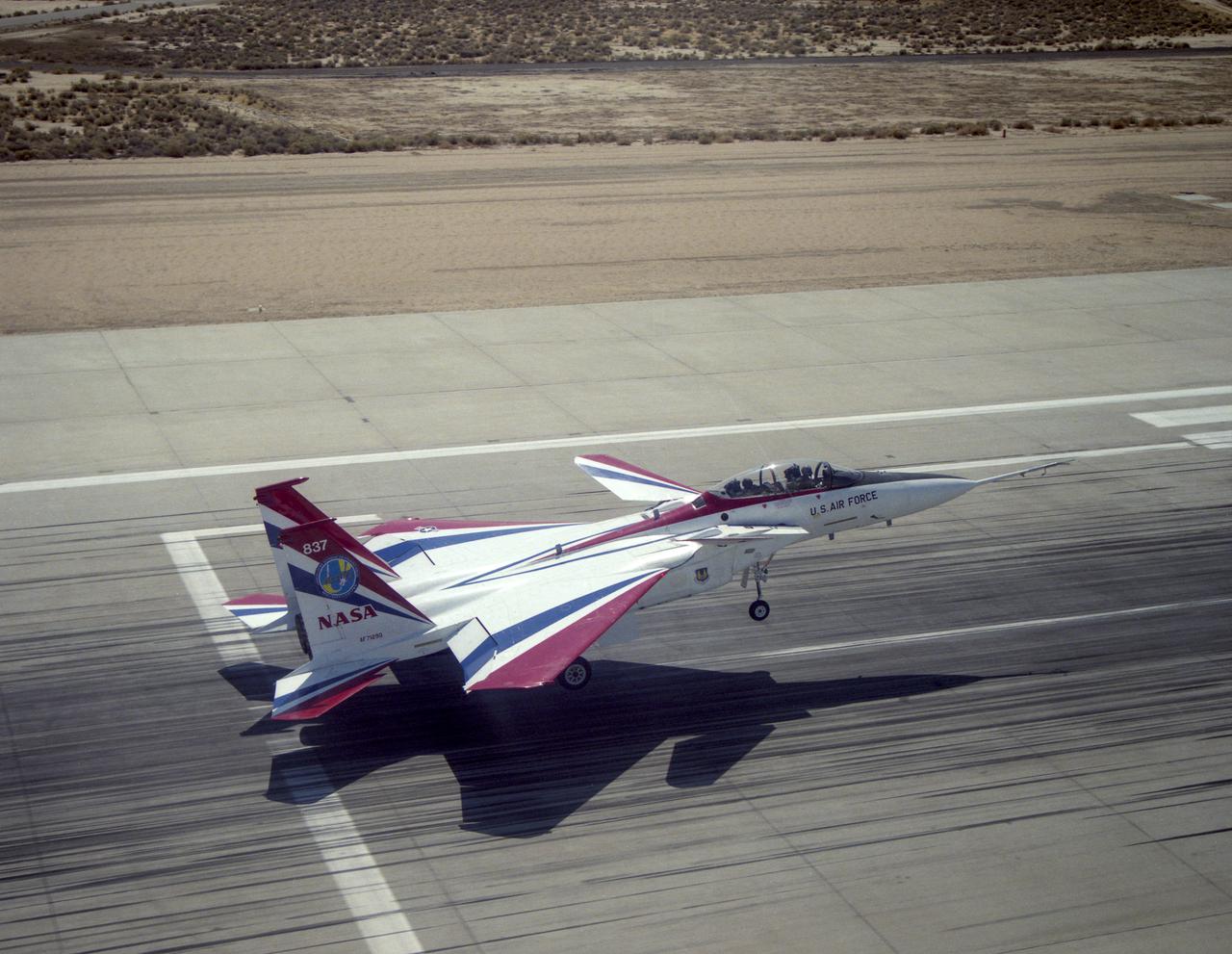
The F-15 Advanced Controls Technology for Integrated Vehicles, the first pre-production F-15B, shows its canards. Less obvious are the multi-axis thrust vectoring exhaust nozzles.
N-238 60MW Aerodynamic Heating Facility outside of test section with Jean Brian (Arc heater, high pressure water manifold, & water cooled 8' conical nozzle)
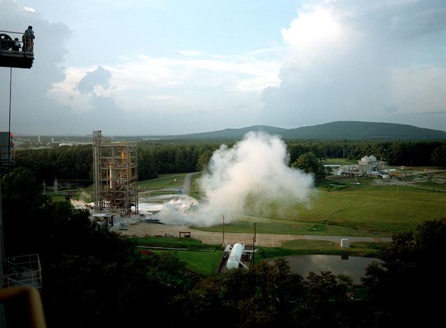
24 inch Hybrid motor test firing at Marshall's Test Stand 500. Liquid/gas are mixed with solid propellents to investigate materials, propellents, and nozzle stability characteristics.
Teams at NASA’s Stennis Space Center install a second production nozzle, left, on Feb. 6 to gather additional performance data on the RS-25 certification engine at the Fred Haise Test Stand.

N-238 60MW Aerodynamic Heating Facility outside of test section with Jean Brian (Arch heater, high pressure water manifold, & water cooled 8' conical nozzle)
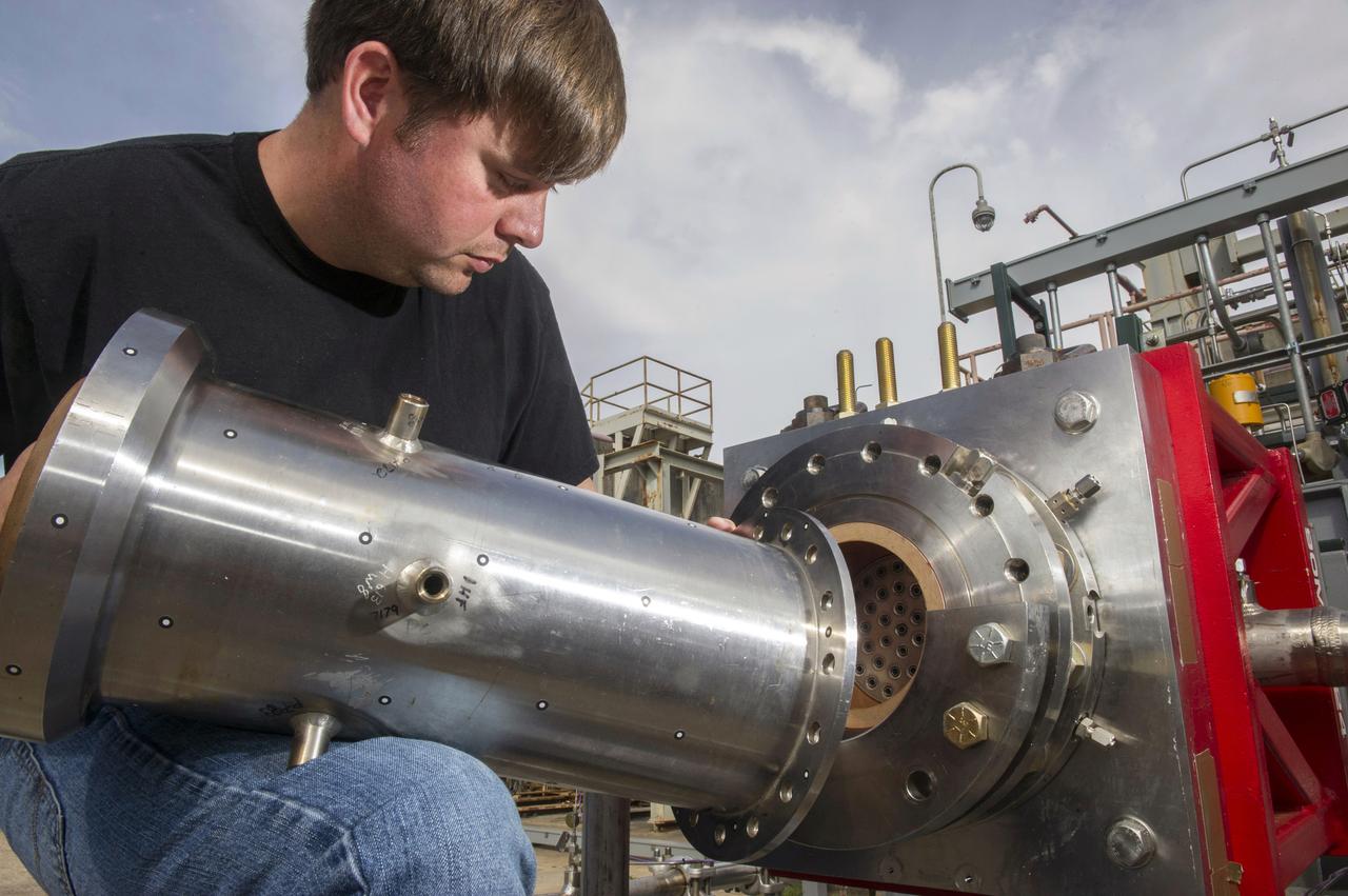
1. ENGINEERS AND TECHNICIANS PREPARE FOR AN UPCOMING HOT-FIRE TEST OF A ROCKET INJECTOR MANUFACTURED USING ADDITIVE MANUFACTURING, OR 3-D PRINTING…RANDALL MCALLISTER, INFOPRO TECHNICIAN, FITS NOZZLE TO ROCKET INJECTOR
N-238 60MW Aerodynamic Heating Facility outside of test section with Jean Brian (Arc heater, high pressure water manifold, & water cooled 8' conical nozzle)
Shown is the installation of O-rings in the aft nozzle section in support of the Ares/CLV First Stage at ATK in Utah. This image is extracted from a high definition video file and is the highest resolution available
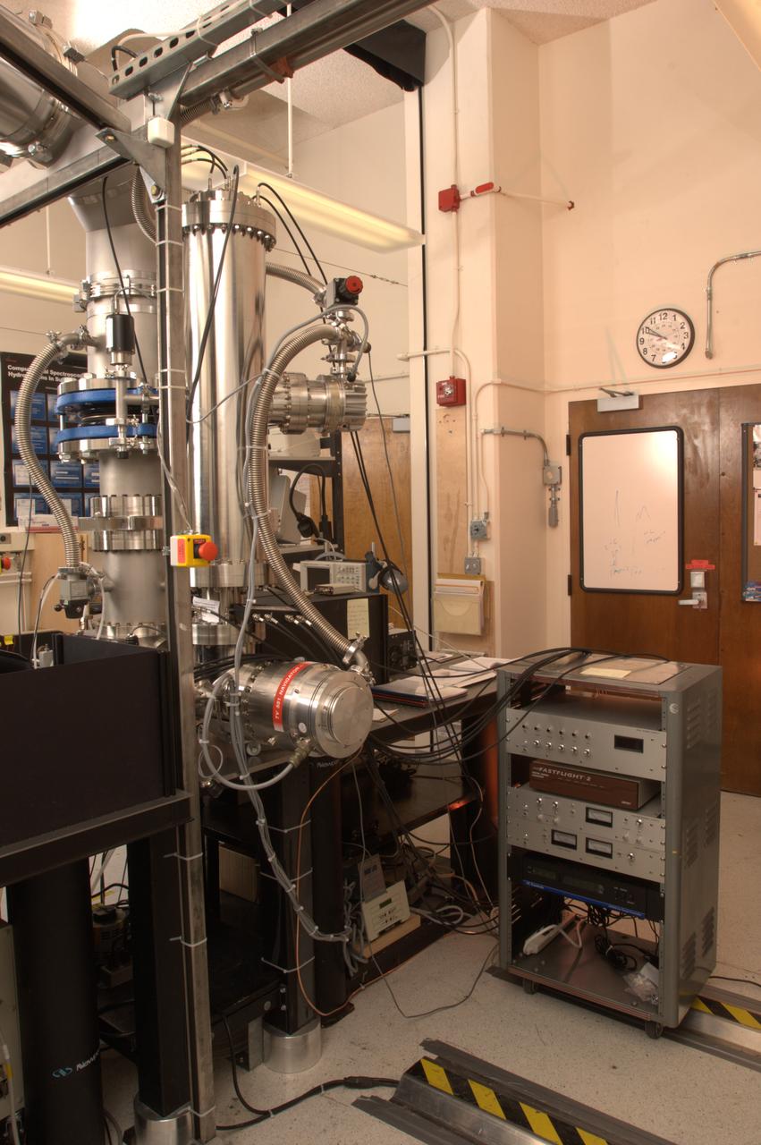
NASA Ames Astrophysics Branch (code-SSA), Pulsed discharge nozzle - Cavity Ring down - Reflection Time of Flight Mass Spectrometer (N-245 rm B-31) (PDN-CRDS-RETOFMS)
HOT FIRE P9038-SRTMV-N1 24". THE FIRST SUBSCALE MOTOR FOR THE ARES PROGRAM. THE PRIMARY OBJECTIVE FOR THE TEST IS TO ESTABLISH A BASELINE SUBSCALE CONFIGURATION FOR THE ARES 1ST STAGE NOZZLE.
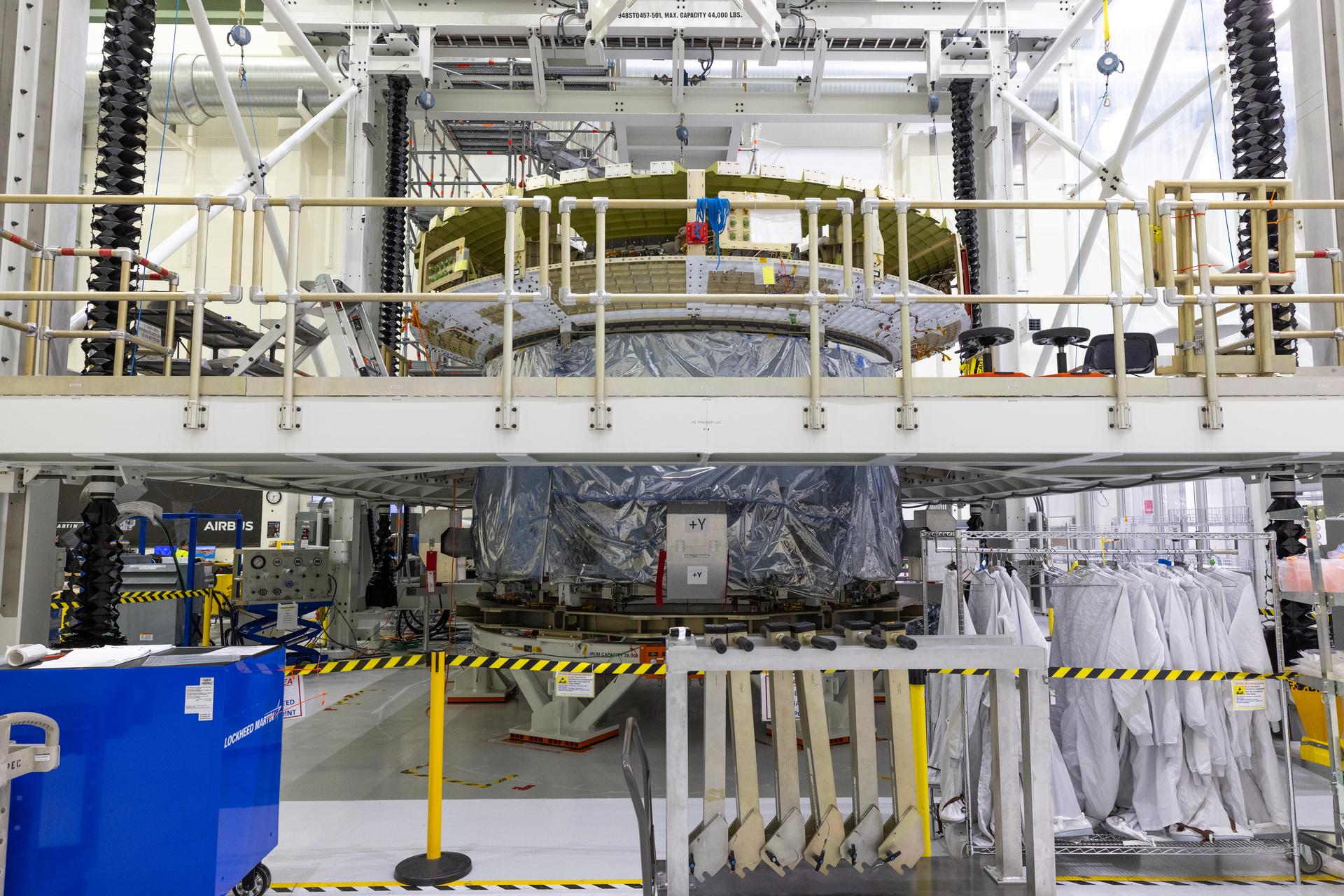
The European Service Module and crew module adapter for NASA’s Artemis IV mission is seen on a work stand on the right, while the Orion crew module for the agency’s Artemis V mission can be seen in the background inside the high bay of the Neil A. Armstrong Operations and Checkout Building at NASA’s Kennedy Space Center in Florida on Tuesday, Feb. 17, 2026. The Orion crew module is the astronaut habitat and reentry capsule, while the European Service Module provides propulsion, power, and life-support resources during Artemis missions. Under Artemis, NASA will send astronauts on increasingly difficult missions to explore more of the Moon for scientific discovery, economic benefits, and to build on our foundation for the first crewed missions to Mars.
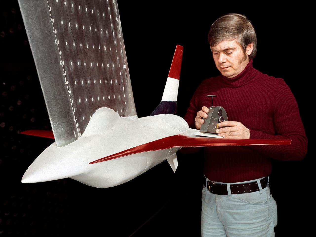
A model of the General Dynamics YF-16 Fighting Falcon in the test section of the 8- by 6-Foot Supersonic Wind Tunnel at the National Aeronautics and Space Administration (NASA) Lewis Research Center. The YF-16 was General Dynamics response to the military’s 1972 request for proposals to design a new 20,000-pound fighter jet with exceptional acceleration, turn rate, and range. The aircraft included innovative design elements to help pilots survive turns up to 9Gs, a new frameless bubble canopy, and a Pratt and Whitney 24,000-pound thrust F-100 engine. The YF-16 made its initial flight in February 1974, just six weeks before this photograph, at Edwards Air Force Base. Less than a year later, the Air Force ordered 650 of the aircraft, designated as F-16 Fighting Falcons. The March and April 1974 tests in the 8- by 6-foot tunnel analyzed the aircraft’s fixed-shroud ejector nozzle. The fixed-nozzle area limited drag, but also limited the nozzle’s internal performance. NASA researchers identified and assessed aerodynamic and aerodynamic-propulsion interaction uncertainties associated the prototype concept. YF-16 models were also tested extensively in the 11- by 11-Foot Transonic Wind Tunnel and 9- by 7-Foot Supersonic Wind Tunnel at Ames Research Center and the 12-Foot Pressure Wind Tunnel at Langley Research Center.
The augmentor wing concept was introduced during the early 1960s to enhance the performance of vertical and short takeoff (VSTOL) aircraft. The leading edge of the wing has full-span vertical flaps, and the trailing edge has double-slotted flaps. This provides aircraft with more control in takeoff and landing conditions. The augmentor wing also produced lower noise levels than other VSTOL designs. In the early 1970s Boeing Corporation built a Buffalo C-8A augmentor wing research aircraft for Ames Research Center. Researches at Lewis Research Center concentrated their efforts on reducing the noise levels of the wing. They initially used small-scale models to develop optimal nozzle screening methods. They then examined the nozzle designs on a large-scale model, seen here on an external test stand. This test stand included an airflow system, nozzle, the augmentor wing, and a muffler system below to reduce the atmospheric noise levels. The augmentor was lined with noise-reducing acoustic panels. The Lewis researchers were able to adjust the airflow to simulate conditions at takeoff and landing. Once the conditions were stabilized they took noise measurements from microphones placed in all directions from the wing, including an aircraft flying over. They found that the results coincided with the earlier small-scale studies for landing situations but not takeoffs. The acoustic panels were found to be successful.
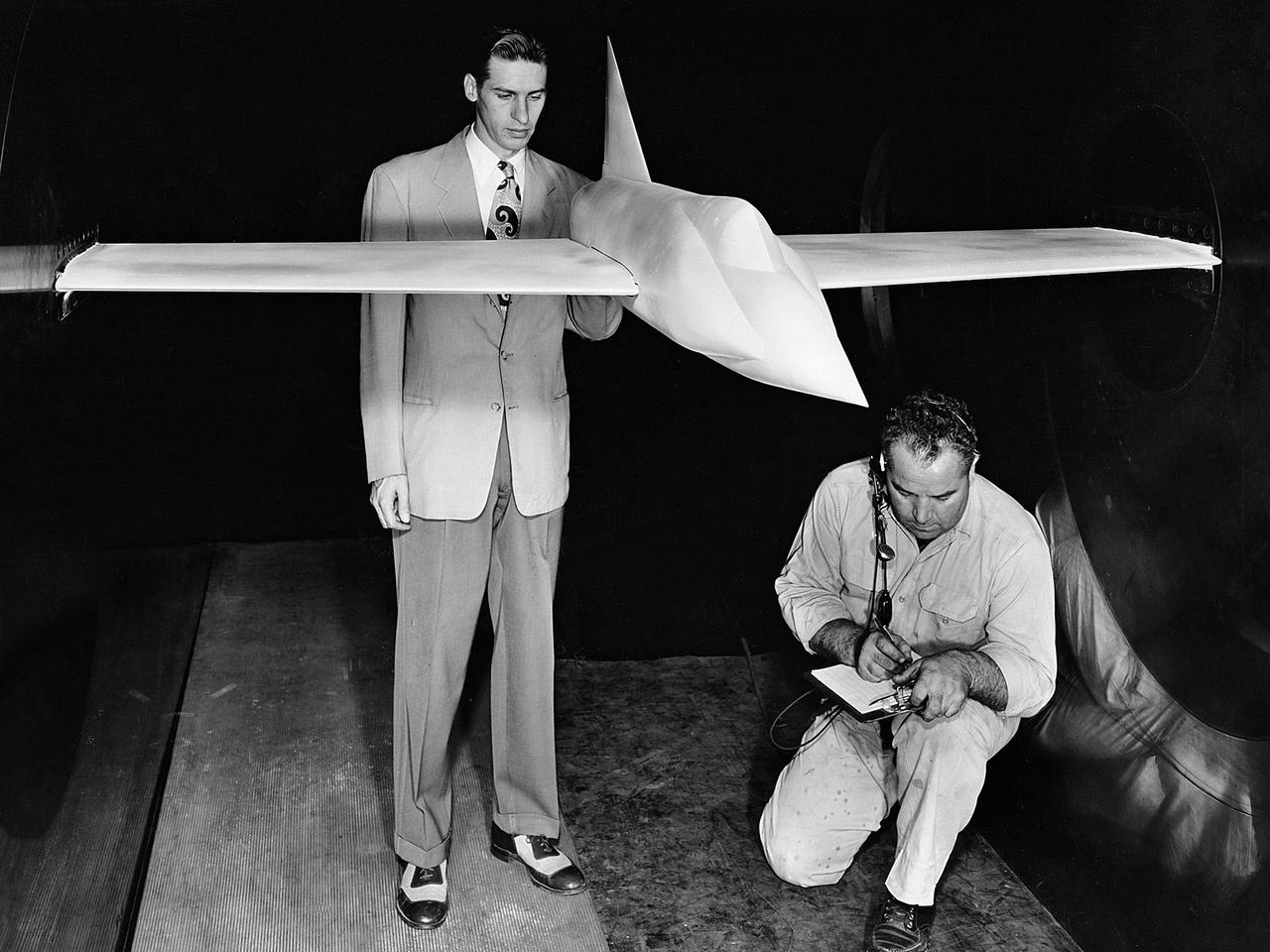
A .10-scale model of Convair’s XF-102 in the 8- by 6-Foot Supersonic Wind Tunnel at the National Advisory Committee for Aeronautics (NACA) Lewis Flight Propulsion Laboratory for jet exit studies. The XF-102 was a prototype of the F-102 Delta Dagger. The F-102 served as an interceptor against long range bombers from the Soviet Union. The aircraft was powered by a Pratt and Whitney J57 turbojet. The first prototype crashed two weeks after is first flight on October 24, 1953, just months after this photograph. Engineers then incorporated the fixed-wing design to reduce drag at supersonic speeds. The production model F-102 became the first delta-wing supersonic aircraft in operation. The 8- by 6-Foot Supersonic Wind Tunnel is used to study propulsion systems, including inlets and exit nozzles, combustion fuel injectors, flame holders, exit nozzles, and controls on ramjet and turbojet engines. Flexible sidewalls alter the tunnel’s nozzle shape to vary the Mach number during operation. A seven-stage axial compressor, driven by three electric motors that yield a total of 87,000 horsepower, generates air speeds from Mach 0.36 to 2.0.
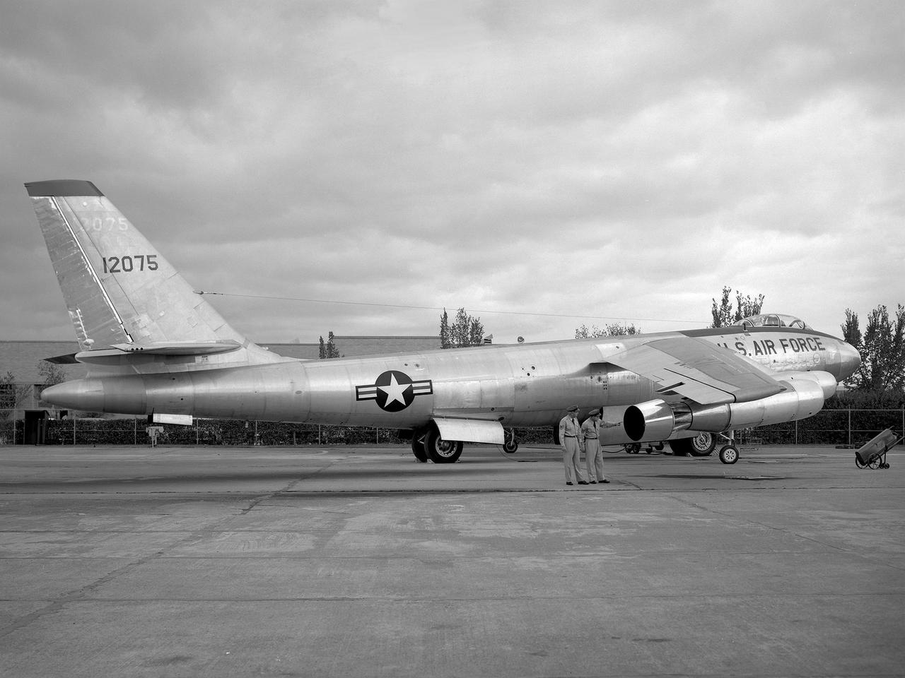
A Boeing B-47 Stratojet bomber with a noise-reducing ejector on its engine at the 1957 Inspection of the National Advisory Committee for Aeronautics (NACA) Lewis Flight Propulsion Laboratory. Representatives from the military, aeronautical industry, universities, and the press were invited to the laboratory to be briefed on the NACA’s latest research efforts and tour the state- of- the- art test facilities. Over 1700 people visited the NACA Lewis in Cleveland, Ohio during October 7 - 10, 1957. By the mid-1950s, the aircraft industry was close to introducing jet airliners to the nation’s airways. The noise produced by the large jet engines, however, would pose a considerable problem for communities near airports. This problem was demonstrated at the 1957 Inspection by an NACA Lewis researcher who played longplay (LP) audio records of military jet engines for an audience. Tests showed that the source of the loudest noise was not the engine itself, but the mixing of the engine’s exhaust with the surrounding air in the atmosphere. The pressures resulting from this turbulence produced sound waves. One of Lewis’ first studies sought to design an exhaust nozzle that reduced the turbulence. A Pratt and Whitney J57 was tested in the Altitude Wind Tunnel with many of these nozzle configurations from January to May 1957. Researchers found that the various nozzle types did reduce the noise levels but also reduced the aircraft’s thrust. Afterwards, they determined that the addition of an NACA-developed ejector reduced the noise levels without diminishing thrust.
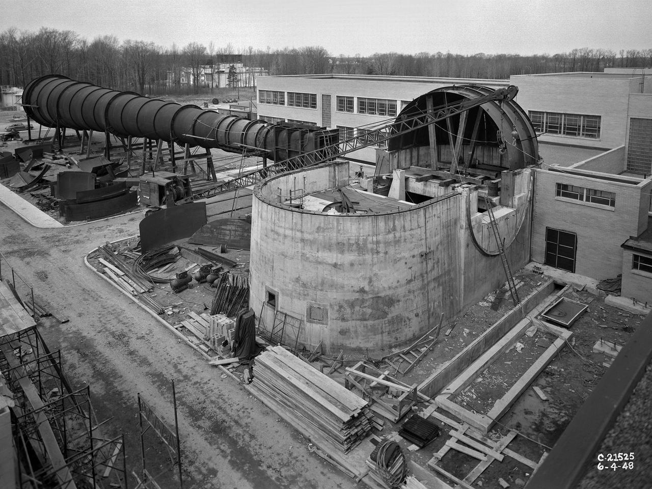
The 8- by 6-Foot Supersonic Wind Tunnel at the National Advisory Committee for Aeronautics (NACA) Lewis Flight Propulsion Laboratory was the nation’s largest supersonic facility when it began operation in April 1949. The emergence of new propulsion technologies such as turbojets, ramjets, and rockets during World War II forced the NACA and the aircraft industry to develop new research tools. In late 1945 the NACA began design work for new large supersonic wind tunnels at its three laboratories. The result was the 4- by 4-Foot Supersonic Wind Tunnel at Langley Memorial Aeronautical Laboratory, 6- by 6-foot supersonic wind tunnel at Ames Aeronautical Laboratory, and the largest facility, the 8- by 6-Foot Supersonic Wind Tunnel in Cleveland. The two former tunnels were to study aerodynamics, while the 8- by 6 facility was designed for supersonic propulsion. The 8- by 6-Foot Supersonic Wind Tunnel was used to study propulsion systems, including inlets and exit nozzles, combustion fuel injectors, flame holders, exit nozzles, and controls on ramjet and turbojet engines. Flexible sidewalls alter the tunnel’s nozzle shape to vary the Mach number during operation. A seven-stage axial compressor, driven by three electric motors that yield a total of 87,000 horsepower, generates air speeds from Mach 0.36 to 2.0. A section of the tunnel is seen being erected in this photograph.
The roman candle effect as seen in this picture represents the testing of a solid rocket booster (SRB) for unexplained corrosion conditions (EUCC) which have occurred on the nozzles of redesigned solid rocket motors (RSRM). The motor being tested in this photo is a 48 M-NASA motor.
L59-8368 Spherical 5 Inch rocket motor with radio beacon mounted as a torus around the nozzle. View shows motor as used in trailblazer I vehicles. Photograph published in A New Dimension Wallops Island Flight Test Range: The First Fifteen Years by Joseph Shortal. A NASA publication. Page 678.
The 10- by 10-Foot Supersonic Wind Tunnel (10×10) is the largest and fastest wind tunnel facility at NASA’s Glenn Research Center and is specifically designed to test supersonic propulsion components from inlets and nozzles to full-scale jet and rocket engines.
cutaway Rockwell International Space Shuttle Main Engines: Powerhead (Left side - fuel preburner, fuel trubopump - Center - Main Combustion Chamber, nozzle forward manifold - Right side - oxidizer preburner, oxidizer turbopump, preburner boost pump)
COLD FLOW - Liquid oxygen runs through the piping on Stennis Space Center's A-1 Test Stand on Dec. 18 to test the ability of the J-2X engine's Powerpack 1A to withstand the temperature change and pressure. Just visible above and to the right of the test article's nozzle is a frosty pipe, indicating the supercold fuel is flowing as it should.
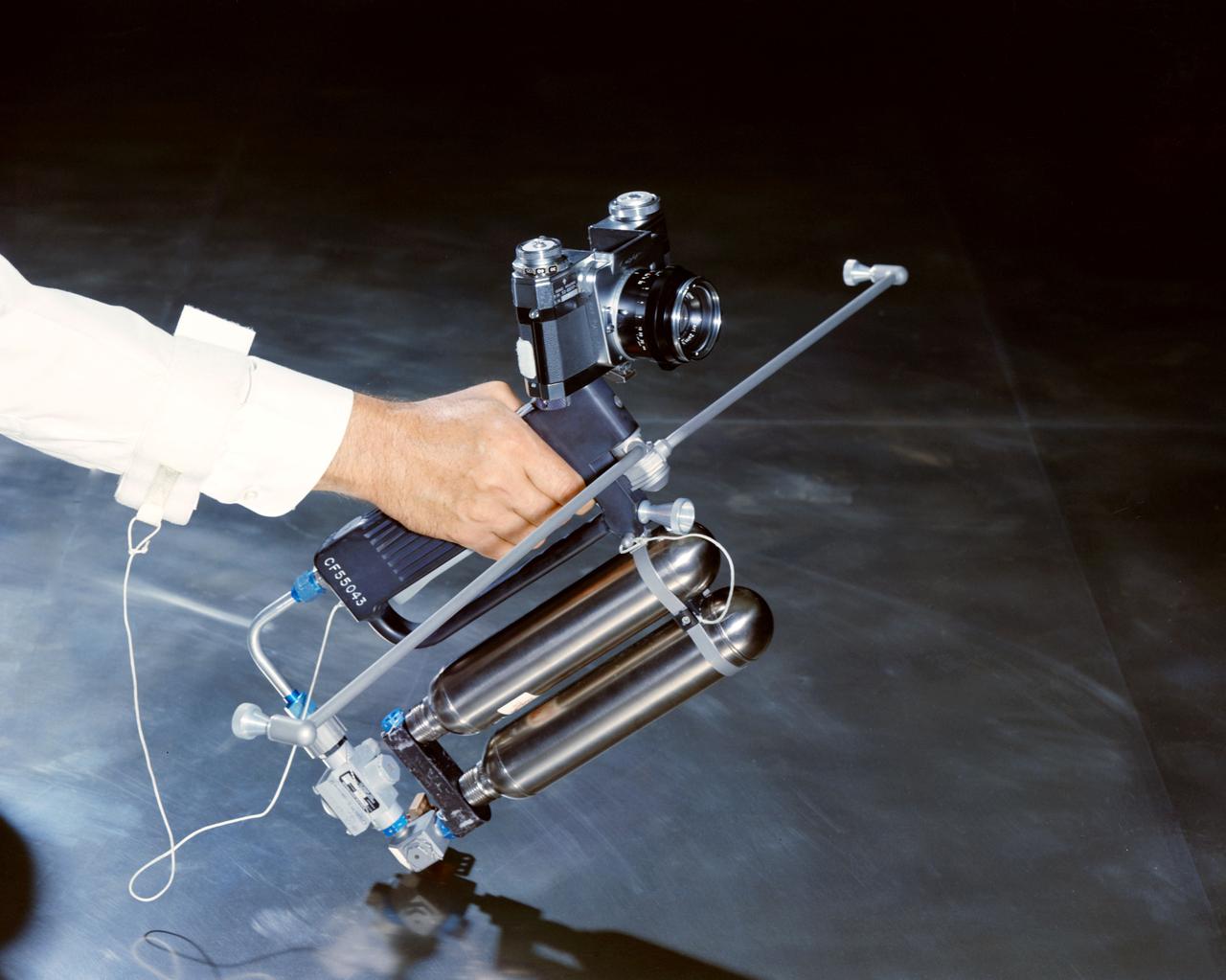
Hand-Held Self-Maneuvering Unit to be used during extravehicular activity (EVA) on Gemini 4 flight. It is an integral unit that contains its own high pressure metering valves and nozzles required to produce controlled thrust. A camera is mounted on the front of the unit.
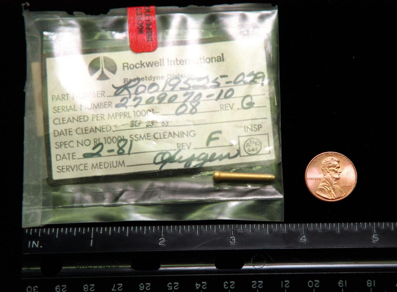
Engineers are investigating the possibility that a 7/8" gold-plated liquid oxygen post plug became dislodged and created three small holes in the liquid hydrogen tubes inside the nozzle on main engine No. 3 on Space Shuttle Columbia. The holes caused a hydrogen leak during the STS-93 launch of Columbia on July 23
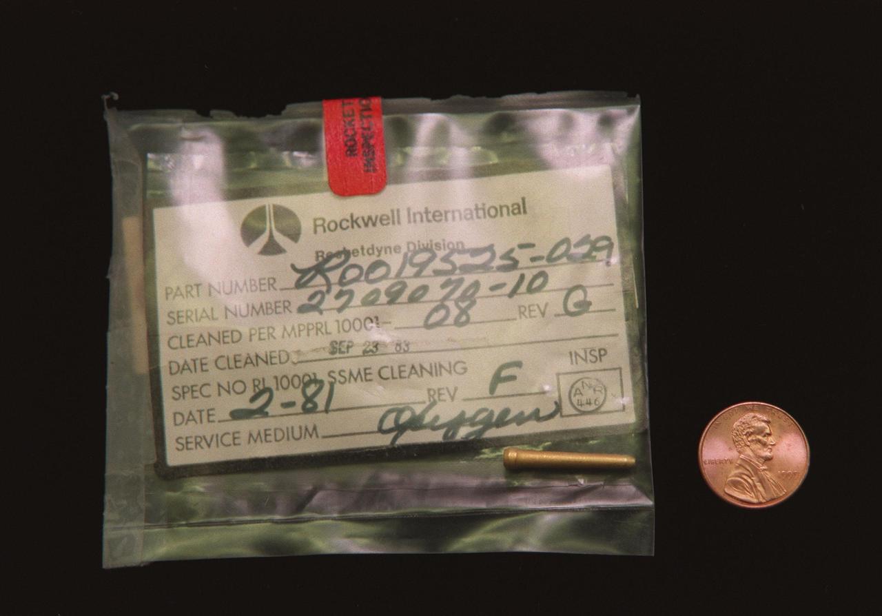
Engineers are investigating the possibility that a 7/8" gold-plated liquid oxygen post plug became dislodged and created three small holes in the liquid hydrogen tubes inside the nozzle on main engine No. 3 on Space Shuttle Columbia. The holes caused a hydrogen leak during the STS-93 launch of Columbia on July 23

Having reached the halfway point in a 12-test RS-25 certification series, teams at NASA’s Stennis Space Center will install a second production nozzle (shown) on the engine to gather additional performance data during the remaining scheduled hot fires.
The Laminar Soot Processes (LSP) Experiment Mounting Structure (EMS) was used to conduct the LSP experiment on Combustion Module-1. The EMS was inserted into the nozzle on the EMS and ignited by a hot wire igniter. The flame and its soot emitting properties were studied.
Technicians monitor the positioning of a large workstand as it is carefully moved into place around the main engine nozzles of Space Shuttle Endeavour during deservicing and ferry flight preparations at NASA's Dryden Flight Research Center at Edwards Air Force Base.
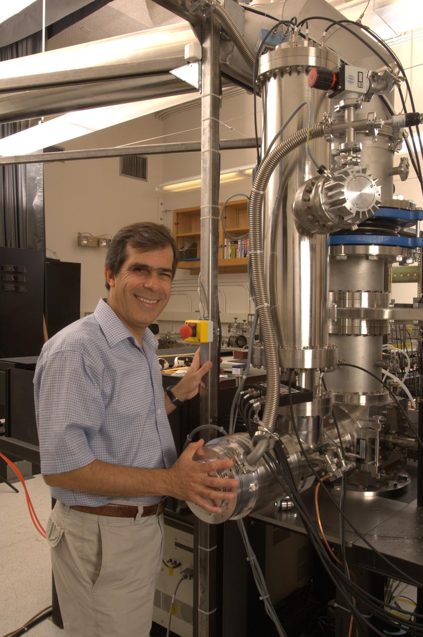
NASA Ames Astrophysics Branch (code-SSA), Pulsed discharge nozzle - Cavity Ring down - Reflection Time of Flight Mass Spectrometer (N-245 rm B-31) (PDN-CRDS-RETOFMS) shown here with Farid Salama
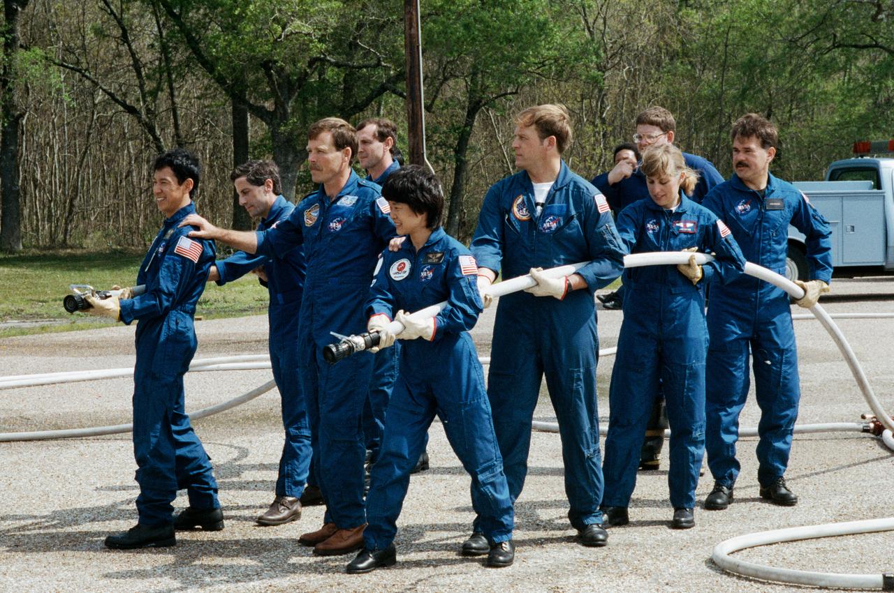
STS-47 Endeavour, Orbiter Vehicle (OV) 105, crewmembers led by Commander Robert L. Gibson (center) prepare to extinguish a blaze in JSC's Fire Training Pit. Lined up along the water hoses are: (on left) Payload Specialist Mamoru Mohri, holding the hose nozzle, followed by Mission Specialist (MS) Jerome Apt, and Pilot Curtis L. Brown, Jr; and (on right) backup Payload Specialist Chiaki Naito-Mukai, holding the hose nozzle, followed by MS and Payload Commander (PLC) Mark C. Lee, MS N. Jan Davis, and backup Payload Specialist Stan Koszelak. A veteran fire fighter and the instructor, positioned between the two hoses, looks on. Mohri and Mukai represent Japan's National Space Development Agency (NASDA). The Fire Training Pit is located across from the Gilruth Center Bldg 207.
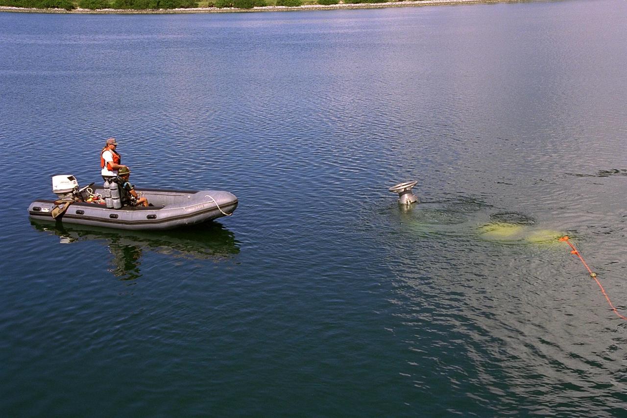
KENNEDY SPACE CENTER, FLA. -- A scuba diver stands by as the unmanned Max Rover submersible goes down to insert a Diver Operated Plug (DOP) into an aft nozzle like the ones used on the Space Shuttle's solid rocket boosters (SRBs). NASA and contractor Deep Sea Systems demonstrated the submersible at Port Canaveral's Trident pier. Kennedy Space Center's SRB retrieval team and Advanced Systems Development laboratory staff hope that the new robotic technology will make the process of inserting the plug into spent SRBs safer and less strenuous. Currently, scuba divers manually insert the DOP into the aft nozzle of a jettisoned SRB 60 to 70 feet below the surface of the Atlantic Ocean. After the plug is installed, water is pumped out of the booster allowing it to float horizontally. It is then towed back to Hangar AF at Cape Canaveral Air Station for refurbishment. Deep Sea Systems of Falmouth, Mass., built the submersible for NASA
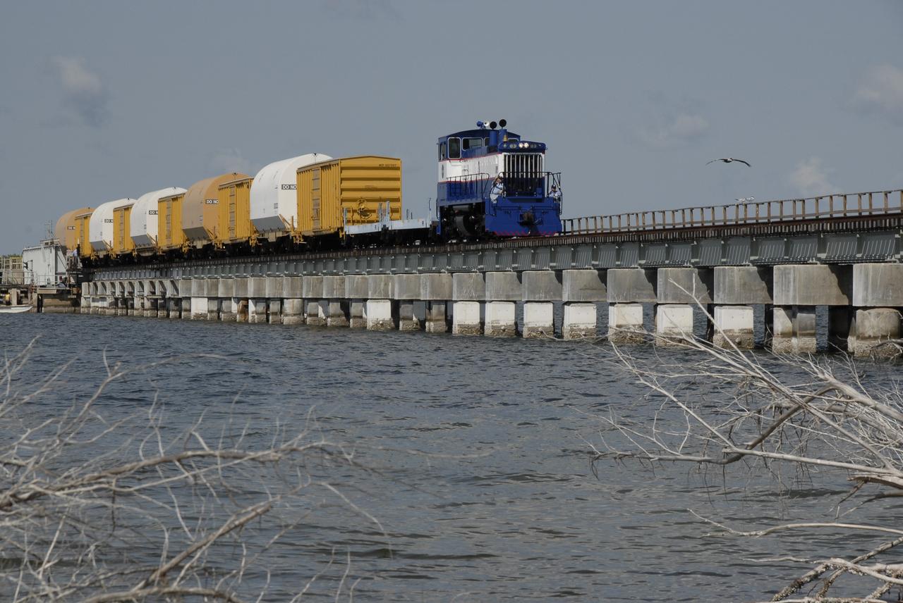
CAPE CANAVERAL, Fla. – The NASA Railroad hauls cars carrying the Ares I-X motor segments and nozzle exit cone over a river bridge to NASA's Kennedy Space Center in Florida. The four reusable motor segments and the nozzle exit cone, manufactured by the Ares I first-stage prime contractor Alliant Techsystems Inc., or ATK, departed Utah March 12 on the seven-day, cross-country trip to Florida. The segments will be delivered to Kennedy's Rotation, Processing and Surge Facility for final processing and integration. The booster used for the Ares I-X launch is being modified by adding new forward structures and a fifth segment simulator. The motor is the final hardware needed for the rocket's upcoming test flight this summer. The stacking operations are scheduled to begin in the Vehicle Assembly Building in April. Photo credit: NASA/Kim Shiflett
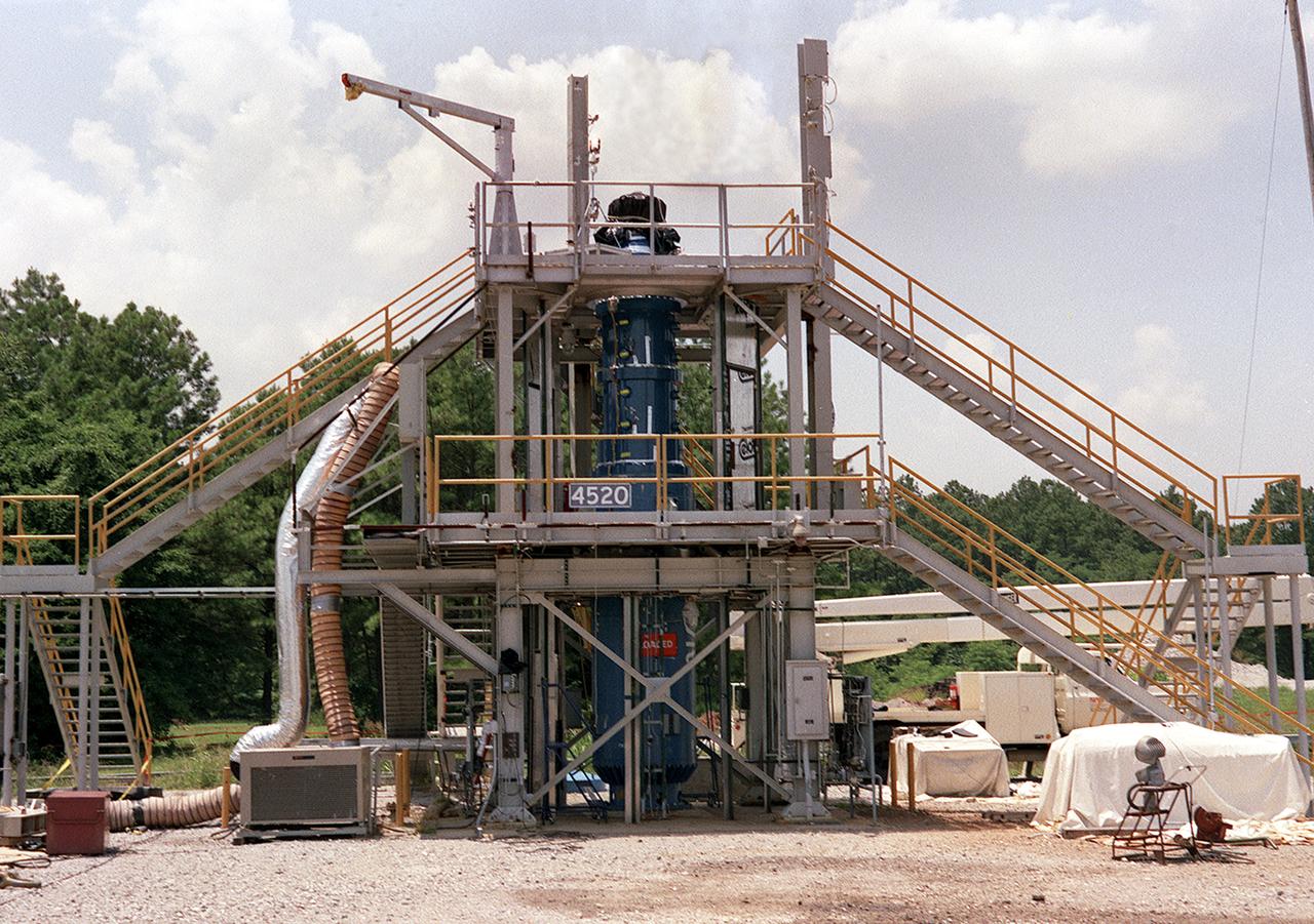
This photograph shows the Solid Propellant Test Article (SPTA) test stand with the Modified Nasa Motor (M-NASA) test article at the Marshall Space Flight Center (MSFC). The SPTA test stand, 12-feet wide by 12-feet long by 24-feet high, was built in 1989 to provide comparative performance data on nozzle and case insulation material and to verify thermostructural analysis models. A modified NASA 48-inch solid motor (M-NASA motor) with a 12-foot blast tube and 10-inch throat makes up the SPTA. The M-NASA motor is being used to evaluate solid rocket motor internal non-asbestos insulation materials, nozzle designs, materials, and new inspection techniques. New internal motor case instrumentation techniques are also being evaluated.

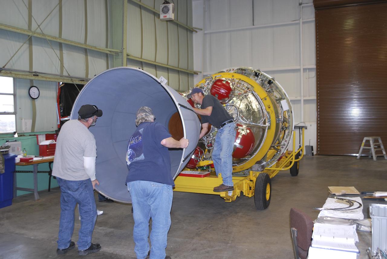
KENNEDY SPACE CENTER, FLA. - At the Delta Operations Center on Cape Canaveral Air Force Station, Fla., technicians Duane Miller (left) and Ed Wagner (right) help guide the Delta second stage nozzle for a Boeing Delta IV launch vehicle away from its shipping container. The nozzle is being moved to another site on the floor for inspection. The Delta IV is scheduled to launch the GOES-N satellite in May 2005. Geostationary Operational Environmental Satellites are sponsored by the National Aeronautics and Space Administration (NASA) and the National Oceanic and Atmospheric Administration (NOAA). GOES-N is the first in the next series of GOES satellites, N-P. The multimission GOES series N-P will be a vital contributor to weather, solar and space operations and science. The GOES N-P series will aid activities ranging from severe storm warnings to resource management and advances in science.

KENNEDY SPACE CENTER, FLA. - At the Delta Operations Center on Cape Canaveral Air Force Station, Fla., technicians Duane Miller (left) and Ed Wagner (right) help guide the Delta second stage nozzle for a Boeing Delta IV launch vehicle away from its shipping container. The nozzle is being moved to another site on the floor for inspection. The Delta IV is scheduled to launch the GOES-N satellite in May 2005. Geostationary Operational Environmental Satellites are sponsored by the National Aeronautics and Space Administration (NASA) and the National Oceanic and Atmospheric Administration (NOAA). GOES-N is the first in the next series of GOES satellites, N-P. The multimission GOES series N-P will be a vital contributor to weather, solar and space operations and science. The GOES N-P series will aid activities ranging from severe storm warnings to resource management and advances in science.
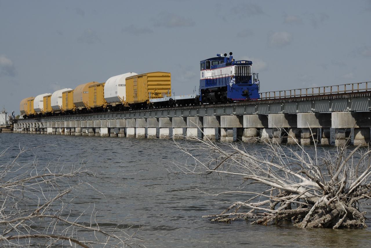
CAPE CANAVERAL, Fla. – The NASA Railroad hauls cars carrying the Ares I-X motor segments and nozzle exit cone over a river bridge to NASA's Kennedy Space Center in Florida. The four reusable motor segments and the nozzle exit cone, manufactured by the Ares I first-stage prime contractor Alliant Techsystems Inc., or ATK, departed Utah March 12 on the seven-day, cross-country trip to Florida. The segments will be delivered to Kennedy's Rotation, Processing and Surge Facility for final processing and integration. The booster used for the Ares I-X launch is being modified by adding new forward structures and a fifth segment simulator. The motor is the final hardware needed for the rocket's upcoming test flight this summer. The stacking operations are scheduled to begin in the Vehicle Assembly Building in April. Photo credit: NASA/Kim Shiflett
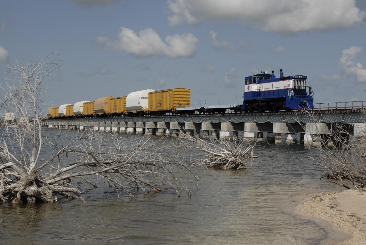
CAPE CANAVERAL, Fla. – The NASA Railroad hauls cars carrying the Ares I-X motor segments and nozzle exit cone over a river bridge to NASA's Kennedy Space Center in Florida. The four reusable motor segments and the nozzle exit cone, manufactured by the Ares I first-stage prime contractor Alliant Techsystems Inc., or ATK, departed Utah March 12 on the seven-day, cross-country trip to Florida. The segments will be delivered to Kennedy's Rotation, Processing and Surge Facility for final processing and integration. The booster used for the Ares I-X launch is being modified by adding new forward structures and a fifth segment simulator. The motor is the final hardware needed for the rocket's upcoming test flight this summer. The stacking operations are scheduled to begin in the Vehicle Assembly Building in April. Photo credit: NASA/Kim Shiflett

KENNEDY SPACE CENTER, FLA. - At the Delta Operations Center on Cape Canaveral Air Force Station, Fla., Tibor Nagy and Bob McMillan, at left, make the initial nozzle inspection of the Delta second stage nozzle for a Boeing Delta IV launch vehicle. The Delta IV is scheduled to launch the GOES-N satellite in May 2005. Geostationary Operational Environmental Satellites are sponsored by the National Aeronautics and Space Administration (NASA) and the National Oceanic and Atmospheric Administration (NOAA). GOES-N is the first in the next series of GOES satellites, N-P. The multimission GOES series N-P will be a vital contributor to weather, solar and space operations and science. The GOES N-P series will aid activities ranging from severe storm warnings to resource management and advances in science.

KENNEDY SPACE CENTER, FLA. - At the Delta Operations Center on Cape Canaveral Air Force Station, Fla., Wendell Perez checks an overhead crane being attached to the Delta second stage nozzle for a Boeing Delta IV launch vehicle. The nozzle is being lifted from its shipping container and moved to another site on the floor for inspection. The Delta IV is scheduled to launch the GOES-N satellite in May 2005. Geostationary Operational Environmental Satellites are sponsored by the National Aeronautics and Space Administration (NASA) and the National Oceanic and Atmospheric Administration (NOAA). GOES-N is the first in the next series of GOES satellites, N-P. The multimission GOES series N-P will be a vital contributor to weather, solar and space operations and science. The GOES N-P series will aid activities ranging from severe storm warnings to resource management and advances in science.
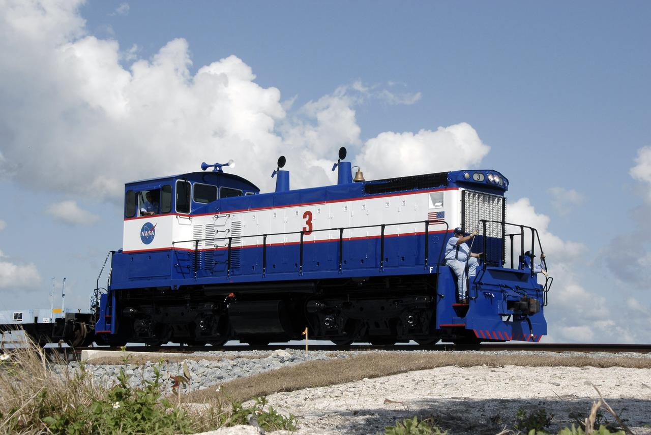
CAPE CANAVERAL, Fla. – A close-up of the NASA Railroad locomotive #3, and the EMDSW-1500 switcher, that is hauling the Ares I-X motor segments and nozzle exit cone to NASA's Kennedy Space Center in Florida. The four reusable motor segments and the nozzle exit cone, manufactured by the Ares I first-stage prime contractor Alliant Techsystems Inc., or ATK, departed Utah March 12 on the seven-day, cross-country trip to Florida. The segments will be delivered to Kennedy's Rotation, Processing and Surge Facility for final processing and integration. The booster used for the Ares I-X launch is being modified by adding new forward structures and a fifth segment simulator. The motor is the final hardware needed for the rocket's upcoming test flight this summer. The stacking operations are scheduled to begin in the Vehicle Assembly Building in April. Photo credit: NASA/Kim Shiflett

KENNEDY SPACE CENTER, FLA. -- Technicians lower the unmanned robotic submersible recovery system, known as Max Rover, into the water at the Trident Pier at Port Canaveral during a test of the system. Kennedy Space Center's solid rocket booster (SRB) retrieval team and Advanced Systems Development laboratory staff hope that the new robotic technology will make the process of inserting the Diver Operated Plug (DOP) into the aft nozzle of a spent SRB safer and less strenuous. Currently, scuba divers manually insert the DOP into the aft nozzle of a jettisoned SRB 60 to 70 feet below the surface of the Atlantic Ocean. After the plug is installed, water is pumped out of the booster allowing it to float horizontally. It is then towed back to Hangar AF at Cape Canaveral Air Station. Deep Sea Systems of Falmouth, Mass., built the submersible for NASA
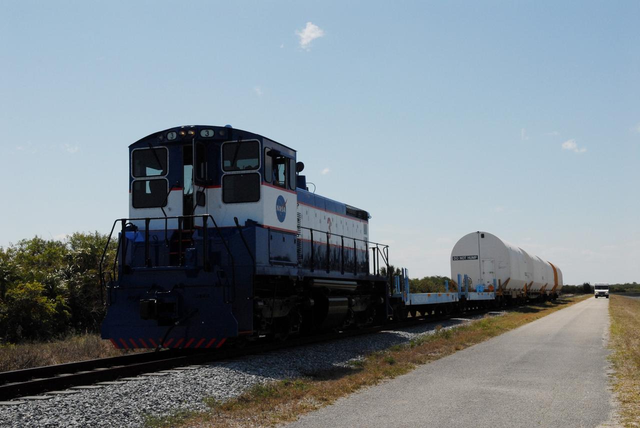
CAPE CANAVERAL, Fla. – After switching out the box cars on the train, the NASA Railroad hauls the Ares I-X motor segments and nozzle exit cone to NASA's Kennedy Space Center in Florida. The four reusable motor segments and the nozzle exit cone, manufactured by the Ares I first-stage prime contractor Alliant Techsystems Inc., or ATK, departed Utah March 12 on the seven-day, cross-country trip to Florida. The segments will be delivered to Kennedy's Rotation, Processing and Surge Facility for final processing and integration. The booster used for the Ares I-X launch is being modified by adding new forward structures and a fifth segment simulator. The motor is the final hardware needed for the rocket's upcoming test flight this summer. The stacking operations are scheduled to begin in the Vehicle Assembly Building in April. Photo credit: NASA/Jack Pfaller
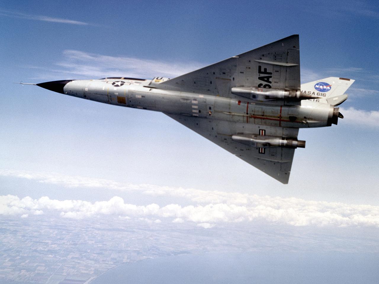
A Convair F-106B Delta Dart rolls to the right to reveal the two research engines installed under its wings by the National Aeronautics and Space Administration (NASA) Lewis Research Center. Lewis acquired the aircraft in October of 1966 to study inlet and nozzle designs for the supersonic transport engine program. Two General Electric J85 engines were mounted beneath the F-106B’s wings and operated from Mach 1 to 1.5. The right wing always carried reference nozzle for which the performance was known. Six supersonic nozzle variations and two inlets were tested on the left engine. The designs had already been studied in the Lewis wind tunnels, but those tests were limited by shock waves in the tunnels. Most F-106B flights were flown in a 200-mile path over the lake between Buffalo and Sandusky, known as the Lake Erie Corridor. The 1100-mile-per-hour flight took only 11 minutes at an altitude of 30,000 feet. The aircraft almost always returned with a depleted fuel supply so a Visual Flight Rules operation was required. Following the crash of another jet fighter at Lewis in July 1969, the F-106s were stationed at Selfridge Air Force Base in Michigan. NASA pilots flew transport planes each morning to the base before commencing the F-106B missions. After the supersonic transport program was cancelled, the F-106B was used as a test bed for additional engine exhaust nozzle configurations. The F-106B was also used to test inlet configurations for the noise reduction program.