In this 1986 artist's concept, the Orbital Maneuvering Vehicle (OMV), undergoes changeout of the Propulsion Module outside the Space Shuttle Cargo Bay. As envisioned by Marshall Space Flight Center plarners, the OMV would be a remotely-controlled free-flying space tug which would place, rendezvous, dock, and retrieve orbital payloads.
Early Program Development
This 1986 artist's concept shows the Orbital Maneuvering Vehicle (OMV) towing a satellite. As envisioned by Marshall Space Flight Center plarners, the OMV would be a remotely-controlled free-flying space tug which would place, rendezvous, dock, and retrieve orbital payloads.
Early Program Development
In this 1988 artist's concept, the Orbital Maneuvering Vehicle (OMV), closes in on a satellite. As envisioned by Marshall Space Flight plarners, the OMV would be a remotely-controlled free-flying space tug which would place, rendezvous, dock, and retrieve orbital payloads.
Early Program Development
In this 1986 artist's concept, the Orbital Maneuvering Vehicle (OMV), at right, prepares to reboost the Hubble Space Telescope after being deployed from an early Space Station configuration (left). As envisioned by Marshall Space Flight Center plarners, the OMV would be a remotely-controlled free-flying space tug which would place, rendezvous, dock, and retrieve orbital payloads.
Early Program Development
In this 1986 artist's concept, the Orbital Maneuvering Vehicle (OMV), is shown without its main propulsion module. Essentially two propulsion vehicles in one, the OMV could be powered by a main propulsion module , or, in its short range vehicle configuration shown here, use its own hydrazine and cold gas thrusters. As envisioned by Marshall Space Flight Center plarners, the OMV would be a remotely-controlled free-flying space tug which would place, rendezvous, dock, and retrieve orbital payloads.
Early Program Development
STS062-42-026 (4-18 March 1994) --- This 35mm frame, photographed as the Space Shuttle Columbia was orbiting Earth during a "night" pass, documents the glow phenomenon surrounding the vertical stabilizer and the Orbital Maneuvering System (OMS) pods of the spacecraft.
Glow phenomenon surrounding the vertical stabilizer and OMS pods
View of a single engine orbital maneuvering system (OMS) firing on the Discovery. The payload bay is open and the protective canisters for the AUSSAT communications satellite (open) and the ASC-1 are visible. A cloudy Earth's horizon can be seen above the orbiter.
View of the firing of a single engine OMS
SL3-107-1215 (27 Aug. 1973) --- Astronaut Alan L. Bean, Skylab 3 commander, flies the M509 Astronaut Maneuvering Equipment in the forward dome area of the Orbital Workshop (OWS) on the space station cluster in Earth orbit. One of his fellow crewmen took this photograph with a 35mm Nikon camera. Bean is strapped into the back mounted, hand-controlled Automatically Stabilized Maneuvering Unit (ASMU). The dome area is about 22 feet in diameter and 19 feet from top to bottom. Photo credit: NASA
Astronaut Alan Bean flies the Astronaut Maneuvering Equipment
SL3-108-1304 (July-September 1973) --- Astronaut Alan L. Bean, Skylab 3 commander, flies the M509 Astronaut Maneuvering Equipment in the forward dome area of the Orbital Workshop (OWS) on the space station cluster in Earth orbit. Bean is strapped in to the back-mounted, hand-controlled Automatically Stabilized Maneuvering Unit (ASMU). This ASMU experiment is being done in shirt sleeves. The dome area where the experiment is conducted is about 22 feet in diameter and 19 feet from top to bottom. Photo credit: NASA
Astronaut Alan Bean flies the Astronaut Maneuvering Equipment
KENNEDY SPACE CENTER, FLA. - In the Orbiter Processing Facility, an Orbital Maneuvering System (OMS) pod is removed from  the orbiter Atlantis during routine maintenance.
KENNEDY SPACE CENTER, FLA. - In the Orbiter Processing Facility, an Orbital Maneuvering System (OMS) pod is removed from the orbiter Atlantis during routine maintenance.
KENNEDY SPACE CENTER, FLA. - In the Orbiter Processing Facility, an Orbital Maneuvering System (OMS) pod removed from  the orbiter Atlantis during routine maintenance.
KENNEDY SPACE CENTER, FLA. - In the Orbiter Processing Facility, an Orbital Maneuvering System (OMS) pod removed from the orbiter Atlantis during routine maintenance.
KENNEDY SPACE CENTER, FLA. -  In the Orbiter Processing Facility, an Orbital Maneuvering System (OMS) pod is removed from  the orbiter Atlantis during routine maintenance.
KENNEDY SPACE CENTER, FLA. - In the Orbiter Processing Facility, an Orbital Maneuvering System (OMS) pod is removed from the orbiter Atlantis during routine maintenance.
KENNEDY SPACE CENTER, FLA. -  In the Orbiter Processing Facility, technicians prepare to remove an Orbital Maneuvering System (OMS) pod from the orbiter Atlantis during routine maintenance.
KENNEDY SPACE CENTER, FLA. - In the Orbiter Processing Facility, technicians prepare to remove an Orbital Maneuvering System (OMS) pod from the orbiter Atlantis during routine maintenance.
S83-35782 (18 June 1983) --- An Orbital Maneuvering System (OMS) engine firing caused this bright glow at the aft end of the Earth-orbiting space shuttle Challenger on June 18, 1983.  Also visible in the 70mm exposure are parts of the Shuttle Pallet Satellite (SPAS-01). The experiment package for NASA's Office of Space and Terrestrial Applications (OSTA-2), the protective cradles for the Indonesian Palapa-B and Telesat Canada Anik C2 satellites, some getaway special (GAS) canisters and the Canadian-built Remote Manipulator System (RMS). The firing took place less than an hour after deployment of Anik.  Photo credit: NASA
OMS engine firing
KENNEDY SPACE CENTER, FLA. -  In the Orbiter Processing Facility, Rick Beckwith (center), an orbiter engineer with United Space Alliance, explains to the media the reinstallation of the Reinforced Carbon-Carbon panels on the orbiter Atlantis’ wing leading edge.  The media was invited to tour the OPF at KSC and to see the orbiter Atlantis as it is being prepared for Return to Flight.  Both local and national reporters representing print and TV networks were able to see work in progress on Atlantis, also including wiring inspections and checks of the engines in the Orbital Maneuvering System.
KENNEDY SPACE CENTER, FLA. - In the Orbiter Processing Facility, Rick Beckwith (center), an orbiter engineer with United Space Alliance, explains to the media the reinstallation of the Reinforced Carbon-Carbon panels on the orbiter Atlantis’ wing leading edge. The media was invited to tour the OPF at KSC and to see the orbiter Atlantis as it is being prepared for Return to Flight. Both local and national reporters representing print and TV networks were able to see work in progress on Atlantis, also including wiring inspections and checks of the engines in the Orbital Maneuvering System.
KENNEDY SPACE CENTER, FLA. -   In the Orbiter Processing Facility,  the media photograph work being done on the tiles on the orbiter Atlantis as it is being prepared for Return to Flight in the Orbiter Processing Facility.   Both local and national reporters representing print and TV networks were able to see work in progress on Atlantis, including the reinstallation of the Reinforced Carbon-Carbon panels on the orbiter’s wing leading edge; wiring inspections; and checks of the engines in the Orbital Maneuvering System.
KENNEDY SPACE CENTER, FLA. - In the Orbiter Processing Facility, the media photograph work being done on the tiles on the orbiter Atlantis as it is being prepared for Return to Flight in the Orbiter Processing Facility. Both local and national reporters representing print and TV networks were able to see work in progress on Atlantis, including the reinstallation of the Reinforced Carbon-Carbon panels on the orbiter’s wing leading edge; wiring inspections; and checks of the engines in the Orbital Maneuvering System.
KENNEDY SPACE CENTER, FLA. -  In the Orbiter Processing Facility,  the media photograph work being done on the tiles on the orbiter Atlantis as it is being prepared for Return to Flight in the Orbiter Processing Facility.   Both local and national reporters representing print and TV networks were able to see work in progress on Atlantis, including the reinstallation of the Reinforced Carbon-Carbon panels on the orbiter’s wing leading edge; wiring inspections; and checks of the engines in the Orbital Maneuvering System.
KENNEDY SPACE CENTER, FLA. - In the Orbiter Processing Facility, the media photograph work being done on the tiles on the orbiter Atlantis as it is being prepared for Return to Flight in the Orbiter Processing Facility. Both local and national reporters representing print and TV networks were able to see work in progress on Atlantis, including the reinstallation of the Reinforced Carbon-Carbon panels on the orbiter’s wing leading edge; wiring inspections; and checks of the engines in the Orbital Maneuvering System.
KENNEDY SPACE CENTER, FLA. -  In the Orbiter Processing Facility (OPF), Rick Beckwith, an orbiter engineer with United Space Alliance, explains to the media the reinstallation of the Reinforced Carbon-Carbon panels on the orbiter Atlantis’ wing leading edge.  The media was invited to tour the OPF at KSC and to see the orbiter Atlantis as it is being prepared for Return to Flight.  Both local and national reporters representing print and TV networks were able to see work in progress on Atlantis, also including wiring inspections and checks of the engines in the Orbital Maneuvering System.
KENNEDY SPACE CENTER, FLA. - In the Orbiter Processing Facility (OPF), Rick Beckwith, an orbiter engineer with United Space Alliance, explains to the media the reinstallation of the Reinforced Carbon-Carbon panels on the orbiter Atlantis’ wing leading edge. The media was invited to tour the OPF at KSC and to see the orbiter Atlantis as it is being prepared for Return to Flight. Both local and national reporters representing print and TV networks were able to see work in progress on Atlantis, also including wiring inspections and checks of the engines in the Orbital Maneuvering System.
This illustration shows NASA's Lunar Flashlight carrying out a trajectory correction maneuver with the Moon and Earth in the background. Powered by the small satellite's four thrusters, the maneuver is needed to reach lunar orbit.  Lunar Flashlight launched Nov. 30, 2022, and will take about four months to reach its science orbit to seek out surface water ice in the darkest craters of the Moon's South Pole. A technology demonstration, the small satellite, or SmallSat, will use a reflectometer equipped with four lasers that emit near-infrared light in wavelengths readily absorbed by surface water ice.  To achieve the mission's goals with the satellite's limited amount of propellent, Lunar Flashlight will employ an energy-efficient near-rectilinear halo orbit, taking it within 9 miles (15 kilometers) of the lunar South Pole and 43,000 miles (70,000 kilometers) away at its farthest point. Only one other spacecraft has employed this type of orbit: NASA's Cislunar Autonomous Positioning System Technology Operations and Navigation Experiment (CAPSTONE) mission, which launched in June 2022.  https://photojournal.jpl.nasa.gov/catalog/PIA25258
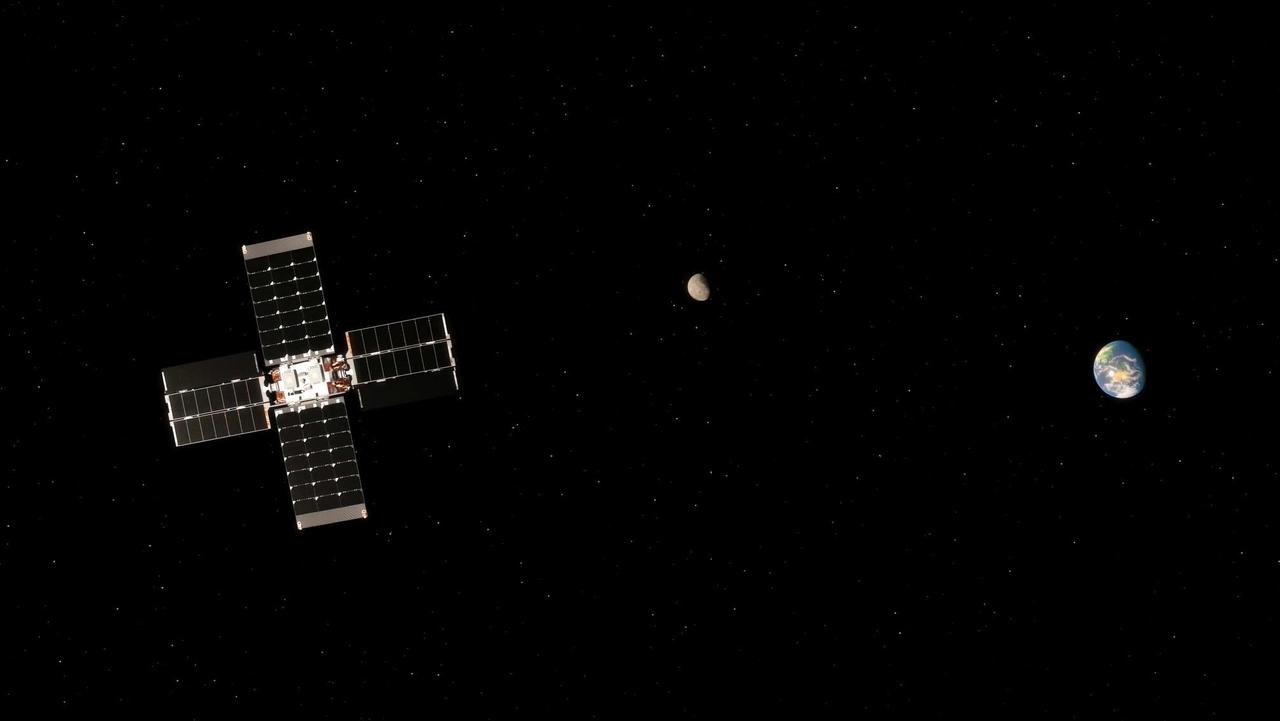
Lunar Flashlight's Trajectory Correction Maneuver (Illustration)
KENNEDY SPACE CENTER, FLA. -  NASA Vehicle Manager Scott Thurston (facing camera) talks to the media in the Orbiter Processing Facility.  The media was invited to see the orbiter Atlantis as it is being prepared for Return to Flight.  Both local and national reporters representing print and TV networks were able to see work in progress on Atlantis, including the reinstallation of the Reinforced Carbon-Carbon panels on the orbiter’s wing leading edge; wiring inspections; and checks of the engines in the Orbital Maneuvering System.
KENNEDY SPACE CENTER, FLA. - NASA Vehicle Manager Scott Thurston (facing camera) talks to the media in the Orbiter Processing Facility. The media was invited to see the orbiter Atlantis as it is being prepared for Return to Flight. Both local and national reporters representing print and TV networks were able to see work in progress on Atlantis, including the reinstallation of the Reinforced Carbon-Carbon panels on the orbiter’s wing leading edge; wiring inspections; and checks of the engines in the Orbital Maneuvering System.
KENNEDY SPACE CENTER, FLA. -  NASA Vehicle Manager Scott Thurston talks to the media in the Orbiter Processing Facility.  The media was invited to see the orbiter Atlantis as it is being prepared for Return to Flight.  Both local and national reporters representing print and TV networks were able to see work in progress on Atlantis, including the reinstallation of the Reinforced Carbon-Carbon panels on the orbiter’s wing leading edge; wiring inspections; and checks of the engines in the Orbital Maneuvering System.
KENNEDY SPACE CENTER, FLA. - NASA Vehicle Manager Scott Thurston talks to the media in the Orbiter Processing Facility. The media was invited to see the orbiter Atlantis as it is being prepared for Return to Flight. Both local and national reporters representing print and TV networks were able to see work in progress on Atlantis, including the reinstallation of the Reinforced Carbon-Carbon panels on the orbiter’s wing leading edge; wiring inspections; and checks of the engines in the Orbital Maneuvering System.
KENNEDY SPACE CENTER, FLA. - NASA Vehicle Manager Scott Thurston (left) talks to a phalanx of media in the Orbiter Processing Facility.  The media was invited to see the orbiter Atlantis as it is being prepared for Return to Flight.  Both local and national reporters representing print and TV networks were able to see work in progress on Atlantis, including the reinstallation of the Reinforced Carbon-Carbon panels on the orbiter’s wing leading edge; wiring inspections; and checks of the engines in the Orbital Maneuvering System.
KENNEDY SPACE CENTER, FLA. - NASA Vehicle Manager Scott Thurston (left) talks to a phalanx of media in the Orbiter Processing Facility. The media was invited to see the orbiter Atlantis as it is being prepared for Return to Flight. Both local and national reporters representing print and TV networks were able to see work in progress on Atlantis, including the reinstallation of the Reinforced Carbon-Carbon panels on the orbiter’s wing leading edge; wiring inspections; and checks of the engines in the Orbital Maneuvering System.
KENNEDY SPACE CENTER, FLA. -  NASA Vehicle Manager Scott Thurston (facing camera) talks to the media in the Orbiter Processing Facility.  The media was invited to see the orbiter Atlantis as it is being prepared for Return to Flight.  Both local and national reporters representing print and TV networks were able to see work in progress on Atlantis, including the reinstallation of the Reinforced Carbon-Carbon panels on the orbiter’s wing leading edge; wiring inspections; and checks of the engines in the Orbital Maneuvering System.
KENNEDY SPACE CENTER, FLA. - NASA Vehicle Manager Scott Thurston (facing camera) talks to the media in the Orbiter Processing Facility. The media was invited to see the orbiter Atlantis as it is being prepared for Return to Flight. Both local and national reporters representing print and TV networks were able to see work in progress on Atlantis, including the reinstallation of the Reinforced Carbon-Carbon panels on the orbiter’s wing leading edge; wiring inspections; and checks of the engines in the Orbital Maneuvering System.
KENNEDY SPACE CENTER, FLA. -   The media gather around NASA Vehicle Manager Scott Thurston (white shirt, right) who talks about some of the work being done on the orbiter Atlantis as it is being prepared for Return to Flight in the Orbiter Processing Facility.   Both local and national reporters representing print and TV networks were able to see work in progress on Atlantis, including the reinstallation of the Reinforced Carbon-Carbon panels on the orbiter’s wing leading edge; wiring inspections; and checks of the engines in the Orbital Maneuvering System.
KENNEDY SPACE CENTER, FLA. - The media gather around NASA Vehicle Manager Scott Thurston (white shirt, right) who talks about some of the work being done on the orbiter Atlantis as it is being prepared for Return to Flight in the Orbiter Processing Facility. Both local and national reporters representing print and TV networks were able to see work in progress on Atlantis, including the reinstallation of the Reinforced Carbon-Carbon panels on the orbiter’s wing leading edge; wiring inspections; and checks of the engines in the Orbital Maneuvering System.
KENNEDY SPACE CENTER, FLA. -   NASA Vehicle Manager Scott Thurston (right)  talks to the media in the Orbiter Processing Facility.  The media was invited to see the orbiter Atlantis as it is being prepared for Return to Flight.  Both local and national reporters representing print and TV networks were able to see work in progress on Atlantis, including the reinstallation of the Reinforced Carbon-Carbon panels on the orbiter’s wing leading edge; wiring inspections; and checks of the engines in the Orbital Maneuvering System.  will be available to discuss the work and answer questions.
KENNEDY SPACE CENTER, FLA. - NASA Vehicle Manager Scott Thurston (right) talks to the media in the Orbiter Processing Facility. The media was invited to see the orbiter Atlantis as it is being prepared for Return to Flight. Both local and national reporters representing print and TV networks were able to see work in progress on Atlantis, including the reinstallation of the Reinforced Carbon-Carbon panels on the orbiter’s wing leading edge; wiring inspections; and checks of the engines in the Orbital Maneuvering System. will be available to discuss the work and answer questions.
KENNEDY SPACE CENTER, FLA. -   NASA Vehicle Manager Scott Thurston (right)  talks to the media in the Orbiter Processing Facility .  The media was invited to see the orbiter Atlantis as it is being prepared for Return to Flight.  Both local and national reporters representing print and TV networks were able to see work in progress on Atlantis, including the reinstallation of the Reinforced Carbon-Carbon panels on the orbiter’s wing leading edge; wiring inspections; and checks of the engines in the Orbital Maneuvering System.
KENNEDY SPACE CENTER, FLA. - NASA Vehicle Manager Scott Thurston (right) talks to the media in the Orbiter Processing Facility . The media was invited to see the orbiter Atlantis as it is being prepared for Return to Flight. Both local and national reporters representing print and TV networks were able to see work in progress on Atlantis, including the reinstallation of the Reinforced Carbon-Carbon panels on the orbiter’s wing leading edge; wiring inspections; and checks of the engines in the Orbital Maneuvering System.
KENNEDY SPACE CENTER, FLA. -   NASA Vehicle Manager Scott Thurston talks to the media in the Orbiter Processing Facility.  The media was invited to see the orbiter Atlantis as it is being prepared for Return to Flight.  Both local and national reporters representing print and TV networks were able to see work in progress on Atlantis, including the reinstallation of the Reinforced Carbon-Carbon panels on the orbiter’s wing leading edge; wiring inspections; and checks of the engines in the Orbital Maneuvering System.
KENNEDY SPACE CENTER, FLA. - NASA Vehicle Manager Scott Thurston talks to the media in the Orbiter Processing Facility. The media was invited to see the orbiter Atlantis as it is being prepared for Return to Flight. Both local and national reporters representing print and TV networks were able to see work in progress on Atlantis, including the reinstallation of the Reinforced Carbon-Carbon panels on the orbiter’s wing leading edge; wiring inspections; and checks of the engines in the Orbital Maneuvering System.
KENNEDY SPACE CENTER, FLA. -   NASA Vehicle Manager Scott Thurston (hands extended) talks to the media in the Orbiter Processing Facility.  The media was invited to see the orbiter Atlantis as it is being prepared for Return to Flight.  Both local and national reporters representing print and TV networks were able to see work in progress on Atlantis, including the reinstallation of the Reinforced Carbon-Carbon panels on the orbiter’s wing leading edge; wiring inspections; and checks of the engines in the Orbital Maneuvering System.
KENNEDY SPACE CENTER, FLA. - NASA Vehicle Manager Scott Thurston (hands extended) talks to the media in the Orbiter Processing Facility. The media was invited to see the orbiter Atlantis as it is being prepared for Return to Flight. Both local and national reporters representing print and TV networks were able to see work in progress on Atlantis, including the reinstallation of the Reinforced Carbon-Carbon panels on the orbiter’s wing leading edge; wiring inspections; and checks of the engines in the Orbital Maneuvering System.
KENNEDY SPACE CENTER, FLA. -  In the Orbiter Processing Facility, the media record workers on the job preparing the orbiter Atlantis for Return to Flight. Both local and national reporters representing print and TV networks were invited to see work in progress on Atlantis, including the reinstallation of the Reinforced Carbon-Carbon panels on the orbiter’s wing leading edge; wiring inspections; and checks of the engines in the Orbital Maneuvering System.
KENNEDY SPACE CENTER, FLA. - In the Orbiter Processing Facility, the media record workers on the job preparing the orbiter Atlantis for Return to Flight. Both local and national reporters representing print and TV networks were invited to see work in progress on Atlantis, including the reinstallation of the Reinforced Carbon-Carbon panels on the orbiter’s wing leading edge; wiring inspections; and checks of the engines in the Orbital Maneuvering System.
KENNEDY SPACE CENTER, FLA. -  In the Orbiter Processing Facility (OPF), Rick Beckwith, an orbiter engineer with United Space Alliance, explains to the media the reinstallation of the Reinforced Carbon-Carbon panels on Atlantis’ wing leading edge.  The media was invited to tour the OPF at KSC and to see the orbiter Atlantis as it is being prepared for Return to Flight.  Both local and national reporters representing print and TV networks were able to see work in progress on Atlantis, also including wiring inspections and checks of the engines in the Orbital Maneuvering System.
KENNEDY SPACE CENTER, FLA. - In the Orbiter Processing Facility (OPF), Rick Beckwith, an orbiter engineer with United Space Alliance, explains to the media the reinstallation of the Reinforced Carbon-Carbon panels on Atlantis’ wing leading edge. The media was invited to tour the OPF at KSC and to see the orbiter Atlantis as it is being prepared for Return to Flight. Both local and national reporters representing print and TV networks were able to see work in progress on Atlantis, also including wiring inspections and checks of the engines in the Orbital Maneuvering System.
KENNEDY SPACE CENTER, FLA. -  In the Orbiter Processing Facility, the left-hand Orbital Maneuvering System (OMS) pod  is maneuvered toward the engine interfaces on the orbiter Discovery for installation.  The Orbital Maneuvering System provides the thrust for orbit insertion, orbit circularization, orbit transfer, rendezvous, deorbit, abort to orbit and abort once around.  It can provide up to 1,000 pounds of propellant to the aft reaction control system.  Each pod contains one OMS engine and the hardware needed to pressurize, store and distribute the propellants to perform the velocity maneuvers.
KSC-04pd0948
KENNEDY SPACE CENTER, FLA. - In the Orbiter Processing Facility, one of two orbital maneuvering system (OMS) pods is being moved for installation on Atlantis.  The OMS pods are attached to the upper aft fuselage left and right sides. Fabricated primarily of graphite epoxy composite and aluminum, each pod is 21.8 feet long and 11.37 feet wide at its aft end and 8.41 feet wide at its forward end, with a surface area of approximately 435 square feet. Each pod houses the Reaction Control System propulsion components used for inflight maneuvering and is attached to the aft fuselage with 11 bolts.
KENNEDY SPACE CENTER, FLA. - In the Orbiter Processing Facility, one of two orbital maneuvering system (OMS) pods is being moved for installation on Atlantis. The OMS pods are attached to the upper aft fuselage left and right sides. Fabricated primarily of graphite epoxy composite and aluminum, each pod is 21.8 feet long and 11.37 feet wide at its aft end and 8.41 feet wide at its forward end, with a surface area of approximately 435 square feet. Each pod houses the Reaction Control System propulsion components used for inflight maneuvering and is attached to the aft fuselage with 11 bolts.
KENNEDY SPACE CENTER, FLA. - In the Orbiter Processing Facility, technicians move an orbital maneuvering system (OMS) pod into the correct position on Atlantis. The OMS pod is one of two that are attached to the upper aft fuselage left and right sides. Fabricated primarily of graphite epoxy composite and aluminum, each pod is 21.8 feet long and 11.37 feet wide at its aft end and 8.41 feet wide at its forward end, with a surface area of approximately 435 square feet. Each pod houses the Reaction Control System propulsion components used for inflight maneuvering and is attached to the aft fuselage with 11 bolts.
KENNEDY SPACE CENTER, FLA. - In the Orbiter Processing Facility, an orbital maneuvering system (OMS) pod is moved into place on Atlantis.  It is one of two OMS pods attached to the upper aft fuselage left and right sides. Fabricated primarily of graphite epoxy composite and aluminum, each pod is 21.8 feet long and 11.37 feet wide at its aft end and 8.41 feet wide at its forward end, with a surface area of approximately 435 square feet. Each pod houses the Reaction Control System propulsion components used for inflight maneuvering and is attached to the aft fuselage with 11 bolts.
KENNEDY SPACE CENTER, FLA. - In the Orbiter Processing Facility, an orbital maneuvering system (OMS) pod is moved into place on Atlantis. It is one of two OMS pods attached to the upper aft fuselage left and right sides. Fabricated primarily of graphite epoxy composite and aluminum, each pod is 21.8 feet long and 11.37 feet wide at its aft end and 8.41 feet wide at its forward end, with a surface area of approximately 435 square feet. Each pod houses the Reaction Control System propulsion components used for inflight maneuvering and is attached to the aft fuselage with 11 bolts.
KENNEDY SPACE CENTER, FLA. - In the Orbiter Processing Facility, workers discuss the next step in moving the orbital maneuvering system (OMS) pod behind them.  The OMS pod will be installed on Atlantis.  Two OMS pods are attached to the upper aft fuselage left and right sides. Fabricated primarily of graphite epoxy composite and aluminum, each pod is 21.8 feet long and 11.37 feet wide at its aft end and 8.41 feet wide at its forward end, with a surface area of approximately 435 square feet. Each pod houses the Reaction Control System propulsion components used for inflight maneuvering and is attached to the aft fuselage with 11 bolts.
KENNEDY SPACE CENTER, FLA. - In the Orbiter Processing Facility, workers discuss the next step in moving the orbital maneuvering system (OMS) pod behind them. The OMS pod will be installed on Atlantis. Two OMS pods are attached to the upper aft fuselage left and right sides. Fabricated primarily of graphite epoxy composite and aluminum, each pod is 21.8 feet long and 11.37 feet wide at its aft end and 8.41 feet wide at its forward end, with a surface area of approximately 435 square feet. Each pod houses the Reaction Control System propulsion components used for inflight maneuvering and is attached to the aft fuselage with 11 bolts.
KENNEDY SPACE CENTER, FLA. -  In the Orbiter Processing Facility, one of two orbital maneuvering system (OMS) pods is lifted off its stand to move it toward Atlantis for installation. The OMS pods are attached to the upper aft fuselage left and right sides. Fabricated primarily of graphite epoxy composite and aluminum, each pod is 21.8 feet long and 11.37 feet wide at its aft end and 8.41 feet wide at its forward end, with a surface area of approximately 435 square feet. Each pod houses the Reaction Control System propulsion components used for inflight maneuvering and is attached to the aft fuselage with 11 bolts.
KENNEDY SPACE CENTER, FLA. - In the Orbiter Processing Facility, one of two orbital maneuvering system (OMS) pods is lifted off its stand to move it toward Atlantis for installation. The OMS pods are attached to the upper aft fuselage left and right sides. Fabricated primarily of graphite epoxy composite and aluminum, each pod is 21.8 feet long and 11.37 feet wide at its aft end and 8.41 feet wide at its forward end, with a surface area of approximately 435 square feet. Each pod houses the Reaction Control System propulsion components used for inflight maneuvering and is attached to the aft fuselage with 11 bolts.
KENNEDY SPACE CENTER, FLA. - In the Orbiter Processing Facility, technicians make final adjustments to the orbital maneuvering system (OMS) pod being installed on Atlantis.   The OMS pod is one of two that are attached to the upper aft fuselage left and right sides. Fabricated primarily of graphite epoxy composite and aluminum, each pod is 21.8 feet long and 11.37 feet wide at its aft end and 8.41 feet wide at its forward end, with a surface area of approximately 435 square feet. Each pod houses the Reaction Control System propulsion components used for inflight maneuvering and is attached to the aft fuselage with 11 bolts.
KENNEDY SPACE CENTER, FLA. - In the Orbiter Processing Facility, technicians make final adjustments to the orbital maneuvering system (OMS) pod being installed on Atlantis. The OMS pod is one of two that are attached to the upper aft fuselage left and right sides. Fabricated primarily of graphite epoxy composite and aluminum, each pod is 21.8 feet long and 11.37 feet wide at its aft end and 8.41 feet wide at its forward end, with a surface area of approximately 435 square feet. Each pod houses the Reaction Control System propulsion components used for inflight maneuvering and is attached to the aft fuselage with 11 bolts.
KENNEDY SPACE CENTER, FLA. - In the Orbiter Processing Facility, one of two orbital maneuvering system (OMS) pods is being moved for installation on Atlantis.  The OMS pods are attached to the upper aft fuselage left and right sides. Fabricated primarily of graphite epoxy composite and aluminum, each pod is 21.8 feet long and 11.37 feet wide at its aft end and 8.41 feet wide at its forward end, with a surface area of approximately 435 square feet. Each pod houses the Reaction Control System propulsion components used for inflight maneuvering and is attached to the aft fuselage with 11 bolts.
KENNEDY SPACE CENTER, FLA. - In the Orbiter Processing Facility, one of two orbital maneuvering system (OMS) pods is being moved for installation on Atlantis. The OMS pods are attached to the upper aft fuselage left and right sides. Fabricated primarily of graphite epoxy composite and aluminum, each pod is 21.8 feet long and 11.37 feet wide at its aft end and 8.41 feet wide at its forward end, with a surface area of approximately 435 square feet. Each pod houses the Reaction Control System propulsion components used for inflight maneuvering and is attached to the aft fuselage with 11 bolts.
KENNEDY SPACE CENTER, FLA. - In the Orbiter Processing Facility, technicians make adjustments to the orbital maneuvering system (OMS) pod being installed on Atlantis.   The OMS pod is one of two that are attached to the upper aft fuselage left and right sides. Fabricated primarily of graphite epoxy composite and aluminum, each pod is 21.8 feet long and 11.37 feet wide at its aft end and 8.41 feet wide at its forward end, with a surface area of approximately 435 square feet. Each pod houses the Reaction Control System propulsion components used for inflight maneuvering and is attached to the aft fuselage with 11 bolts.
KENNEDY SPACE CENTER, FLA. - In the Orbiter Processing Facility, technicians make adjustments to the orbital maneuvering system (OMS) pod being installed on Atlantis. The OMS pod is one of two that are attached to the upper aft fuselage left and right sides. Fabricated primarily of graphite epoxy composite and aluminum, each pod is 21.8 feet long and 11.37 feet wide at its aft end and 8.41 feet wide at its forward end, with a surface area of approximately 435 square feet. Each pod houses the Reaction Control System propulsion components used for inflight maneuvering and is attached to the aft fuselage with 11 bolts.
KENNEDY SPACE CENTER, FLA. -  In the Orbiter Processing Facility, an orbital maneuvering system (OMS) pod is moved closer to Atlantis for installation.  Two OMS pods are attached to the upper aft fuselage left and right sides. Fabricated primarily of graphite epoxy composite and aluminum, each pod is 21.8 feet long and 11.37 feet wide at its aft end and 8.41 feet wide at its forward end, with a surface area of approximately 435 square feet. Each pod houses the Reaction Control System propulsion components used for inflight maneuvering and is attached to the aft fuselage with 11 bolts.
KENNEDY SPACE CENTER, FLA. - In the Orbiter Processing Facility, an orbital maneuvering system (OMS) pod is moved closer to Atlantis for installation. Two OMS pods are attached to the upper aft fuselage left and right sides. Fabricated primarily of graphite epoxy composite and aluminum, each pod is 21.8 feet long and 11.37 feet wide at its aft end and 8.41 feet wide at its forward end, with a surface area of approximately 435 square feet. Each pod houses the Reaction Control System propulsion components used for inflight maneuvering and is attached to the aft fuselage with 11 bolts.
KENNEDY SPACE CENTER, FLA. -  In the Orbiter Processing Facility, an orbital maneuvering system (OMS) pod is suspended in air as it is moved toward Atlantis for installation.  Two OMS pods are attached to the upper aft fuselage left and right sides. Fabricated primarily of graphite epoxy composite and aluminum, each pod is 21.8 feet long and 11.37 feet wide at its aft end and 8.41 feet wide at its forward end, with a surface area of approximately 435 square feet. Each pod houses the Reaction Control System propulsion components used for inflight maneuvering and is attached to the aft fuselage with 11 bolts.
KENNEDY SPACE CENTER, FLA. - In the Orbiter Processing Facility, an orbital maneuvering system (OMS) pod is suspended in air as it is moved toward Atlantis for installation. Two OMS pods are attached to the upper aft fuselage left and right sides. Fabricated primarily of graphite epoxy composite and aluminum, each pod is 21.8 feet long and 11.37 feet wide at its aft end and 8.41 feet wide at its forward end, with a surface area of approximately 435 square feet. Each pod houses the Reaction Control System propulsion components used for inflight maneuvering and is attached to the aft fuselage with 11 bolts.
KENNEDY SPACE CENTER, FLA. -  In the Orbiter Processing Facility, technicians move an orbital maneuvering system (OMS) pod into the correct position on Atlantis. The OMS pod is one of two that are attached to the upper aft fuselage left and right sides. Fabricated primarily of graphite epoxy composite and aluminum, each pod is 21.8 feet long and 11.37 feet wide at its aft end and 8.41 feet wide at its forward end, with a surface area of approximately 435 square feet. Each pod houses the Reaction Control System propulsion components used for inflight maneuvering and is attached to the aft fuselage with 11 bolts.
KENNEDY SPACE CENTER, FLA. - In the Orbiter Processing Facility, technicians move an orbital maneuvering system (OMS) pod into the correct position on Atlantis. The OMS pod is one of two that are attached to the upper aft fuselage left and right sides. Fabricated primarily of graphite epoxy composite and aluminum, each pod is 21.8 feet long and 11.37 feet wide at its aft end and 8.41 feet wide at its forward end, with a surface area of approximately 435 square feet. Each pod houses the Reaction Control System propulsion components used for inflight maneuvering and is attached to the aft fuselage with 11 bolts.
KENNEDY SPACE CENTER, FLA. - In the Orbiter Processing Facility, an orbital maneuvering system (OMS) pod is moved into place on Atlantis.  It is one of two OMS pods attached to the upper aft fuselage left and right sides. Fabricated primarily of graphite epoxy composite and aluminum, each pod is 21.8 feet long and 11.37 feet wide at its aft end and 8.41 feet wide at its forward end, with a surface area of approximately 435 square feet. Each pod houses the Reaction Control System propulsion components used for inflight maneuvering and is attached to the aft fuselage with 11 bolts.
KENNEDY SPACE CENTER, FLA. - In the Orbiter Processing Facility, an orbital maneuvering system (OMS) pod is moved into place on Atlantis. It is one of two OMS pods attached to the upper aft fuselage left and right sides. Fabricated primarily of graphite epoxy composite and aluminum, each pod is 21.8 feet long and 11.37 feet wide at its aft end and 8.41 feet wide at its forward end, with a surface area of approximately 435 square feet. Each pod houses the Reaction Control System propulsion components used for inflight maneuvering and is attached to the aft fuselage with 11 bolts.
KENNEDY SPACE CENTER, FLA. -  In the Orbiter Processing Facility, workers on an upper level watch as the left-hand Orbital Maneuvering System (OMS) pod is lifted high to maneuver it toward the orbiter Discovery for installation.  The Orbital Maneuvering System provides the thrust for orbit insertion, orbit circularization, orbit transfer, rendezvous, deorbit, abort to orbit and abort once around.  It can provide up to 1,000 pounds of propellant to the aft reaction control system.  Each pod contains one OMS engine and the hardware needed to pressurize, store and distribute the propellants to perform the velocity maneuvers.
KSC-04pd0946
KENNEDY SPACE CENTER, FLA. - In the Orbiter Processing Facility, workers stand by as the left-hand Orbital Maneuvering System (OMS) pod is maneuvered toward the engine interfaces on the orbiter Discovery for installation.  The Orbital Maneuvering System provides the thrust for orbit insertion, orbit circularization, orbit transfer, rendezvous, deorbit, abort to orbit and abort once around.  It can provide up to 1,000 pounds of propellant to the aft reaction control system.  Each pod contains one OMS engine and the hardware needed to pressurize, store and distribute the propellants to perform the velocity maneuvers.
KSC-04pd0949
KENNEDY SPACE CENTER, FLA. -  In the Orbiter Processing Facility, a worker on an upper level watches as the left-hand Orbital Maneuvering System (OMS) pod is lifted high to maneuver it toward the orbiter Discovery for installation.  The Orbital Maneuvering System provides the thrust for orbit insertion, orbit circularization, orbit transfer, rendezvous, deorbit, abort to orbit and abort once around.  It can provide up to 1,000 pounds of propellant to the aft reaction control system.  Each pod contains one OMS engine and the hardware needed to pressurize, store and distribute the propellants to perform the velocity maneuvers.
KSC-04pd0945
KENNEDY SPACE CENTER, FLA. - In the Orbiter Processing Facility, the left-hand Orbital Maneuvering System (OMS) pod  is lowered toward the orbiter Discovery for installation.  The Orbital Maneuvering System provides the thrust for orbit insertion, orbit circularization, orbit transfer, rendezvous, deorbit, abort to orbit and abort once around.  It can provide up to 1,000 pounds of propellant to the aft reaction control system.  Each pod contains one OMS engine and the hardware needed to pressurize, store and distribute the propellants to perform the velocity maneuvers.
KSC-04pd0950
KENNEDY SPACE CENTER, FLA. -   Technicians in the Orbiter Processing Facility oversee removal of one of two orbital maneuvering system (OMS) pods from Endeavour.  The OMS pods are attached to the upper aft fuselage left and right sides.  Fabricated primarily of graphite epoxy composite and aluminum, each pod is 21.8 feet long and 11.37 feet wide at its aft end and 8.41 feet wide at its forward end, with a surface area of approximately 435 square feet.  Each pod houses the Reaction Control System propulsion components used for inflight maneuvering and is attached to the aft fuselage with 11 bolts.   OMS pods are removed during Orbiter Major Modifications. Once removed, the OMS pods undergo in-depth structural inspections, system checks and the thrusters are changed out.
KENNEDY SPACE CENTER, FLA. - Technicians in the Orbiter Processing Facility oversee removal of one of two orbital maneuvering system (OMS) pods from Endeavour. The OMS pods are attached to the upper aft fuselage left and right sides. Fabricated primarily of graphite epoxy composite and aluminum, each pod is 21.8 feet long and 11.37 feet wide at its aft end and 8.41 feet wide at its forward end, with a surface area of approximately 435 square feet. Each pod houses the Reaction Control System propulsion components used for inflight maneuvering and is attached to the aft fuselage with 11 bolts. OMS pods are removed during Orbiter Major Modifications. Once removed, the OMS pods undergo in-depth structural inspections, system checks and the thrusters are changed out.
KENNEDY SPACE CENTER, FLA. -  In the Orbiter Processing Facility, one of two orbital maneuvering system (OMS) pods removed from Endeavour is lowered toward a transporter.  The OMS pods are attached to the upper aft fuselage left and right sides.  Fabricated primarily of graphite epoxy composite and aluminum, each pod is 21.8 feet long and 11.37 feet wide at its aft end and 8.41 feet wide at its forward end, with a surface area of approximately 435 square feet.  Each pod houses the Reaction Control System propulsion components used for inflight maneuvering and is attached to the aft fuselage with 11 bolts.   OMS pods are removed during Orbiter Major Modifications. Once removed, the OMS pods undergo in-depth structural inspections, system checks and the thrusters are changed out.
KENNEDY SPACE CENTER, FLA. - In the Orbiter Processing Facility, one of two orbital maneuvering system (OMS) pods removed from Endeavour is lowered toward a transporter. The OMS pods are attached to the upper aft fuselage left and right sides. Fabricated primarily of graphite epoxy composite and aluminum, each pod is 21.8 feet long and 11.37 feet wide at its aft end and 8.41 feet wide at its forward end, with a surface area of approximately 435 square feet. Each pod houses the Reaction Control System propulsion components used for inflight maneuvering and is attached to the aft fuselage with 11 bolts. OMS pods are removed during Orbiter Major Modifications. Once removed, the OMS pods undergo in-depth structural inspections, system checks and the thrusters are changed out.
KENNEDY SPACE CENTER, FLA. -  In the Orbiter Processing Facility, one of two orbital maneuvering system (OMS) pods removed from Endeavour is lowered onto a transporter.  The OMS pods are attached to the upper aft fuselage left and right sides.  Fabricated primarily of graphite epoxy composite and aluminum, each pod is 21.8 feet long and 11.37 feet wide at its aft end and 8.41 feet wide at its forward end, with a surface area of approximately 435 square feet.  Each pod houses the Reaction Control System propulsion components used for inflight maneuvering and is attached to the aft fuselage with 11 bolts.   OMS pods are removed during Orbiter Major Modifications. Once removed, the OMS pods undergo in-depth structural inspections, system checks and the thrusters are changed out.
KENNEDY SPACE CENTER, FLA. - In the Orbiter Processing Facility, one of two orbital maneuvering system (OMS) pods removed from Endeavour is lowered onto a transporter. The OMS pods are attached to the upper aft fuselage left and right sides. Fabricated primarily of graphite epoxy composite and aluminum, each pod is 21.8 feet long and 11.37 feet wide at its aft end and 8.41 feet wide at its forward end, with a surface area of approximately 435 square feet. Each pod houses the Reaction Control System propulsion components used for inflight maneuvering and is attached to the aft fuselage with 11 bolts. OMS pods are removed during Orbiter Major Modifications. Once removed, the OMS pods undergo in-depth structural inspections, system checks and the thrusters are changed out.
KENNEDY SPACE CENTER, FLA. -  Workers in the Orbiter Processing Facility prepare to remove one of two orbital maneuvering system (OMS) pods from Endeavour.  The OMS pods are attached to the upper aft fuselage left and right sides.  Fabricated primarily of graphite epoxy composite and aluminum, each pod is 21.8 feet long and 11.37 feet wide at its aft end and 8.41 feet wide at its forward end, with a surface area of approximately 435 square feet. Each pod houses the Reaction Control System propulsion components used for inflight maneuvering and is attached to the aft fuselage with 11 bolts.   OMS pods are removed during Orbiter Major Modifications. Once removed, the OMS pods undergo in-depth structural inspections, system checks and the thrusters are changed out.
KENNEDY SPACE CENTER, FLA. - Workers in the Orbiter Processing Facility prepare to remove one of two orbital maneuvering system (OMS) pods from Endeavour. The OMS pods are attached to the upper aft fuselage left and right sides. Fabricated primarily of graphite epoxy composite and aluminum, each pod is 21.8 feet long and 11.37 feet wide at its aft end and 8.41 feet wide at its forward end, with a surface area of approximately 435 square feet. Each pod houses the Reaction Control System propulsion components used for inflight maneuvering and is attached to the aft fuselage with 11 bolts. OMS pods are removed during Orbiter Major Modifications. Once removed, the OMS pods undergo in-depth structural inspections, system checks and the thrusters are changed out.
KENNEDY SPACE CENTER, FLA. -   In the Orbiter Processing Facility, one of two orbital maneuvering system (OMS) pods removed from Endeavour is suspended overhead.  The OMS pods are attached to the upper aft fuselage left and right sides.  Fabricated primarily of graphite epoxy composite and aluminum, each pod is 21.8 feet long and 11.37 feet wide at its aft end and 8.41 feet wide at its forward end, with a surface area of approximately 435 square feet.  Each pod houses the Reaction Control System propulsion components used for inflight maneuvering and is attached to the aft fuselage with 11 bolts.   OMS pods are removed during Orbiter Major Modifications. Once removed, the OMS pods undergo in-depth structural inspections, system checks and the thrusters are changed out.
KENNEDY SPACE CENTER, FLA. - In the Orbiter Processing Facility, one of two orbital maneuvering system (OMS) pods removed from Endeavour is suspended overhead. The OMS pods are attached to the upper aft fuselage left and right sides. Fabricated primarily of graphite epoxy composite and aluminum, each pod is 21.8 feet long and 11.37 feet wide at its aft end and 8.41 feet wide at its forward end, with a surface area of approximately 435 square feet. Each pod houses the Reaction Control System propulsion components used for inflight maneuvering and is attached to the aft fuselage with 11 bolts. OMS pods are removed during Orbiter Major Modifications. Once removed, the OMS pods undergo in-depth structural inspections, system checks and the thrusters are changed out.
KENNEDY SPACE CENTER, FLA. -  Workers in the Orbiter Processing Facility prepare to remove one of two orbital maneuvering system (OMS) pods from Endeavour.  The OMS pods are attached to the upper aft fuselage left and right sides.  Fabricated primarily of graphite epoxy composite and aluminum, each pod is 21.8 feet long and 11.37 feet wide at its aft end and 8.41 feet wide at its forward end, with a surface area of approximately 435 square feet. Each pod houses the Reaction Control System propulsion components used for inflight maneuvering and is attached to the aft fuselage with 11 bolts.  OMS pods are removed during Orbiter Major Modifications. Once removed, the OMS pods undergo in-depth structural inspections, system checks and the thrusters are changed out.
KENNEDY SPACE CENTER, FLA. - Workers in the Orbiter Processing Facility prepare to remove one of two orbital maneuvering system (OMS) pods from Endeavour. The OMS pods are attached to the upper aft fuselage left and right sides. Fabricated primarily of graphite epoxy composite and aluminum, each pod is 21.8 feet long and 11.37 feet wide at its aft end and 8.41 feet wide at its forward end, with a surface area of approximately 435 square feet. Each pod houses the Reaction Control System propulsion components used for inflight maneuvering and is attached to the aft fuselage with 11 bolts. OMS pods are removed during Orbiter Major Modifications. Once removed, the OMS pods undergo in-depth structural inspections, system checks and the thrusters are changed out.
KENNEDY SPACE CENTER, FLA. -  Workers in the Orbiter Processing Facility prepare to  remove one of two orbital maneuvering system (OMS) pods from Endeavour.  The OMS pods are attached to the upper aft fuselage left and right sides.  Fabricated primarily of graphite epoxy composite and aluminum, each pod is 21.8 feet long and 11.37 feet wide at its aft end and 8.41 feet wide at its forward end, with a surface area of approximately 435 square feet. Each pod houses the Reaction Control System propulsion components used for inflight maneuvering and is attached to the aft fuselage with 11 bolts.   OMS pods are removed during Orbiter Major Modifications. Once removed, the OMS pods undergo in-depth structural inspections, system checks and the thrusters are changed out.
KENNEDY SPACE CENTER, FLA. - Workers in the Orbiter Processing Facility prepare to remove one of two orbital maneuvering system (OMS) pods from Endeavour. The OMS pods are attached to the upper aft fuselage left and right sides. Fabricated primarily of graphite epoxy composite and aluminum, each pod is 21.8 feet long and 11.37 feet wide at its aft end and 8.41 feet wide at its forward end, with a surface area of approximately 435 square feet. Each pod houses the Reaction Control System propulsion components used for inflight maneuvering and is attached to the aft fuselage with 11 bolts. OMS pods are removed during Orbiter Major Modifications. Once removed, the OMS pods undergo in-depth structural inspections, system checks and the thrusters are changed out.
KENNEDY SPACE CENTER, FLA. -   Technicians in the Orbiter Processing Facility oversee removal of one of two orbital maneuvering system (OMS) pods from Endeavour.  The OMS pods are attached to the upper aft fuselage left and right sides.  Fabricated primarily of graphite epoxy composite and aluminum, each pod is 21.8 feet long and 11.37 feet wide at its aft end and 8.41 feet wide at its forward end, with a surface area of approximately 435 square feet.  Each pod houses the Reaction Control System propulsion components used for inflight maneuvering and is attached to the aft fuselage with 11 bolts.   OMS pods are removed during Orbiter Major Modifications. Once removed, the OMS pods undergo in-depth structural inspections, system checks and the thrusters are changed out.
KENNEDY SPACE CENTER, FLA. - Technicians in the Orbiter Processing Facility oversee removal of one of two orbital maneuvering system (OMS) pods from Endeavour. The OMS pods are attached to the upper aft fuselage left and right sides. Fabricated primarily of graphite epoxy composite and aluminum, each pod is 21.8 feet long and 11.37 feet wide at its aft end and 8.41 feet wide at its forward end, with a surface area of approximately 435 square feet. Each pod houses the Reaction Control System propulsion components used for inflight maneuvering and is attached to the aft fuselage with 11 bolts. OMS pods are removed during Orbiter Major Modifications. Once removed, the OMS pods undergo in-depth structural inspections, system checks and the thrusters are changed out.
KENNEDY SPACE CENTER, FLA. -  In the Orbiter Processing Facility, the left-hand Orbital Maneuvering System (OMS) pod is lifted at an angle from the transporter below.  The OMS pod will be installed on the orbiter Discovery.  The Orbital Maneuvering System provides the thrust for orbit insertion, orbit circularization, orbit transfer, rendezvous, deorbit, abort to orbit and abort once around.  It can provide up to 1,000 pounds of propellant to the aft reaction control system.  Each pod contains one OMS engine and the hardware needed to pressurize, store and distribute the propellants to perform the velocity maneuvers.
KSC-04pd0944
KENNEDY SPACE CENTER, FLA.  - Technicians install the left Orbital Maneuvering System (OMS) pod on Space Shuttle Atlantis in Orbiter Process Facility bay 1. The Orbital Maneuvering System provides the thrust for orbit insertion, orbit circularization, orbit transfer, rendezvous, deorbit, abort to orbit and abort once around. It can provide up to 1,000 pounds of propellant to the aft reaction control system. Each pod contains one OMS engine and the hardware needed to pressurize, store and distribute the propellants to perform the velocity maneuvers.  Atlantis is the designated orbiter to fly on mission STS-121.  The mission has a launch window of July 12 - July 31.
KSC-05pd-0299
KENNEDY SPACE CENTER, FLA.  - Technicians discuss the left Orbital Maneuvering System (OMS) pod installed on Space Shuttle Atlantis today in Orbiter Process Facility bay 1. The Orbital Maneuvering System provides the thrust for orbit insertion, orbit circularization, orbit transfer, rendezvous, deorbit, abort to orbit and abort once around. It can provide up to 1,000 pounds of propellant to the aft reaction control system. Each pod contains one OMS engine and the hardware needed to pressurize, store and distribute the propellants to perform the velocity maneuvers.  Atlantis is the designated orbiter to fly on mission STS-121.  The mission has a launch window of July 12 - July 31.
KSC-05pd-0298
KENNEDY SPACE CENTER, FLA. -  In the Orbiter Processing Facility, the left-hand Orbital Maneuvering System (OMS) pod (seen from the front) is lifted off its transporter.  The OMS pod will be installed on the orbiter Discovery.  The Orbital Maneuvering System provides the thrust for orbit insertion, orbit circularization, orbit transfer, rendezvous, deorbit, abort to orbit and abort once around.  It can provide up to 1,000 pounds of propellant to the aft reaction control system.  Each pod contains one OMS engine and the hardware needed to pressurize, store and distribute the propellants to perform the velocity maneuvers.
KSC-04pd0941
KENNEDY SPACE CENTER, FLA. -  In the Orbiter Processing Facility, workers check the lifting of the left-hand Orbital Maneuvering System (OMS) pod.  The OMS pod will be installed on the orbiter Discovery.  The Orbital Maneuvering System provides the thrust for orbit insertion, orbit circularization, orbit transfer, rendezvous, deorbit, abort to orbit and abort once around.  It can provide up to 1,000 pounds of propellant to the aft reaction control system.  Each pod contains one OMS engine and the hardware needed to pressurize, store and distribute the propellants to perform the velocity maneuvers.
KSC-04pd0943
KENNEDY SPACE CENTER, FLA. -  In the Orbiter Processing Facility, the left-hand Orbital Maneuvering System (OMS) pod (top of photo) is poised behind the engine interfaces on the orbiter Discovery for installation.  The Orbital Maneuvering System provides the thrust for orbit insertion, orbit circularization, orbit transfer, rendezvous, deorbit, abort to orbit and abort once around.  It can provide up to 1,000 pounds of propellant to the aft reaction control system.  Each pod contains one OMS engine and the hardware needed to pressurize, store and distribute the propellants to perform the velocity maneuvers.
KSC-04pd0947
KENNEDY SPACE CENTER, FLA.  - Space Shuttle Atlantis is outfitted with its left Orbital Maneuvering System (OMS) pod in Orbiter Process Facility bay 1. The Orbital Maneuvering System provides the thrust for orbit insertion, orbit circularization, orbit transfer, rendezvous, deorbit, abort to orbit and abort once around. It can provide up to 1,000 pounds of propellant to the aft reaction control system. Each pod contains one OMS engine and the hardware needed to pressurize, store and distribute the propellants to perform the velocity maneuvers.  Atlantis is the designated orbiter to fly on mission STS-121.  The mission has a launch window of July 12 - July 31.
KSC-05pd-0297
KENNEDY SPACE CENTER, FLA. -  In the Orbiter Processing Facility, the left-hand Orbital Maneuvering System (OMS) pod (seen from the back) is lifted off its transporter.  The OMS pod will be installed on the orbiter Discovery.  The Orbital Maneuvering System provides the thrust for orbit insertion, orbit circularization, orbit transfer, rendezvous, deorbit, abort to orbit and abort once around.  It can provide up to 1,000 pounds of propellant to the aft reaction control system.  Each pod contains one OMS engine and the hardware needed to pressurize, store and distribute the propellants to perform the velocity maneuvers.
KSC-04pd0942
KENNEDY SPACE CENTER, FLA.  - In Orbiter Process Facility bay 1, the installation of the left Orbital Maneuvering System (OMS) pod on Space Shuttle Atlantis is complete. The Orbital Maneuvering System provides the thrust for orbit insertion, orbit circularization, orbit transfer, rendezvous, deorbit, abort to orbit and abort once around. It can provide up to 1,000 pounds of propellant to the aft reaction control system. Each pod contains one OMS engine and the hardware needed to pressurize, store and distribute the propellants to perform the velocity maneuvers.  Atlantis is the designated orbiter to fly on mission STS-121.  The mission has a launch window of July 12 - July 31.
KSC-05pd-0300
KENNEDY SPACE CENTER, FLA. -  In the Orbiter Processing Facility,  while a few photographers (left) set up for photos, NASA Vehicle Manager Scott Thurston (right, with arm extended) talks about the Reinforced Carbon-Carbon panel at right.   The media was invited to see the orbiter Atlantis as it is being prepared for Return to Flight.  Both local and national reporters representing print and TV networks were able to see work in progress on Atlantis, including the reinstallation of the Reinforced Carbon-Carbon panels on the orbiter’s wing leading edge; wiring inspections; and checks of the engines in the Orbital Maneuvering System.
KENNEDY SPACE CENTER, FLA. - In the Orbiter Processing Facility, while a few photographers (left) set up for photos, NASA Vehicle Manager Scott Thurston (right, with arm extended) talks about the Reinforced Carbon-Carbon panel at right. The media was invited to see the orbiter Atlantis as it is being prepared for Return to Flight. Both local and national reporters representing print and TV networks were able to see work in progress on Atlantis, including the reinstallation of the Reinforced Carbon-Carbon panels on the orbiter’s wing leading edge; wiring inspections; and checks of the engines in the Orbital Maneuvering System.
KENNEDY SPACE CENTER, FLA. - Local Central Florida television reporters Phil Robertson (left), with WFTV, and Dan Billow (right), with WESH, tape commentaries after a media tour of the Orbiter Processing Facility.  The media was invited to see the orbiter Atlantis as it is being prepared for Return to Flight.  Both local and national reporters representing print and TV networks were able to see work in progress on Atlantis, including the reinstallation of the Reinforced Carbon-Carbon panels on the orbiter’s wing leading edge; wiring inspections; and checks of the engines in the Orbital Maneuvering System.
KENNEDY SPACE CENTER, FLA. - Local Central Florida television reporters Phil Robertson (left), with WFTV, and Dan Billow (right), with WESH, tape commentaries after a media tour of the Orbiter Processing Facility. The media was invited to see the orbiter Atlantis as it is being prepared for Return to Flight. Both local and national reporters representing print and TV networks were able to see work in progress on Atlantis, including the reinstallation of the Reinforced Carbon-Carbon panels on the orbiter’s wing leading edge; wiring inspections; and checks of the engines in the Orbital Maneuvering System.
KENNEDY SPACE CENTER, FLA. -  In the Orbiter Processing Facility, while a few photographers (left) set up for photos of a Reinforced Carbon-Carbon panel at far right, NASA Vehicle Manager Scott Thurston (right) talks to other media.   The media was invited to see the orbiter Atlantis as it is being prepared for Return to Flight.  Both local and national reporters representing print and TV networks were able to see work in progress on Atlantis, including the reinstallation of the Reinforced Carbon-Carbon panels on the orbiter’s wing leading edge; wiring inspections; and checks of the engines in the Orbital Maneuvering System.
KENNEDY SPACE CENTER, FLA. - In the Orbiter Processing Facility, while a few photographers (left) set up for photos of a Reinforced Carbon-Carbon panel at far right, NASA Vehicle Manager Scott Thurston (right) talks to other media. The media was invited to see the orbiter Atlantis as it is being prepared for Return to Flight. Both local and national reporters representing print and TV networks were able to see work in progress on Atlantis, including the reinstallation of the Reinforced Carbon-Carbon panels on the orbiter’s wing leading edge; wiring inspections; and checks of the engines in the Orbital Maneuvering System.
STS084-357-008 (15-24 May 1997) --- Photographed through the aft flight deck windows of the Earth-orbiting Space Shuttle Atlantis, this 35mm frame captures a firing of the Orbital Maneuvering System (OMS) engines to perform a necessary maneuver. The vertical stabilizer, flanked by the two OMS pods, is illuminated in the scene.
View of OMS burn and illuminated orbiter stabilizer
This artist concept shows NASA Mars orbiters lining up behind the Red Planet for their duck and cover maneuver to shield them from comet dust that may result from the close flyby of comet Siding Spring C/2013 A1 on Oct. 19, 2014.
Mars Orbiters Duck and Cover for Comet Siding Spring Flyby Artist Concept
This artist's rendering shows NASA's Dawn spacecraft maneuvering above Ceres with its ion propulsion system. Dawn arrived into orbit at Ceres on March 6, 2015, and continues to collect data about the mysterious and fascinating world. The mission celebrated its ninth launch anniversary on September 27, 2016.  This illustration is an update to PIA18921, which was produced before Dawn had mapped Ceres' surface.  http://photojournal.jpl.nasa.gov/catalog/PIA20919
Dawn Artist Concept Realistic Ceres
An Orbital Maneuvering System engine at NASA’s Johnson Space Center in Houston on March 28, 2016.
OMS-E Engine
An Orbital Maneuvering System engine at NASA’s Johnson Space Center in Houston on March 28, 2016.
OMS-E Engine
An Orbital Maneuvering System engine at NASA’s Johnson Space Center in Houston on March 28, 2016.
OMS-E Engine
An Orbital Maneuvering System engine at NASA’s Johnson Space Center in Houston on March 28, 2016.
OMS-E Engine
ISS013-E-79880 (11 Sept. 2006) --- This view of part of the  starboard wing and one of the Orbital Maneuvering System (OMS) pods of the Space Shuttle Atlantis was provided by an Expedition 13 crew member during a backflip maneuver performed by the approaching visitors to the International Space Station.
Mapping sequence performed during the STS-115 R-Bar Pitch Maneuver
KENNEDY SPACE CENTER, FLA.  - Workers in the Orbiter Processing Facility watch closely as Discovery’s Forward Reaction Control System (FRCS) is lowered into position in the orbiter’s forward fuselage nose area.  The FRCS provides the thrust for attitude (rotational) maneuvers (pitch, yaw and roll) and for small velocity changes along the orbiter axis (translation maneuvers).  Discovery is designated as the Return to Flight vehicle for mission STS-114, no earlier than March 2005.
KSC-04pd1334
KENNEDY SPACE CENTER, FLA.  - Workers in the Orbiter Processing Facility watch closely as Discovery’s Forward Reaction Control System (FRCS) is lowered into position in the orbiter’s forward fuselage nose area.  The FRCS provides the thrust for attitude (rotational) maneuvers (pitch, yaw and roll) and for small velocity changes along the orbiter axis (translation maneuvers).  Discovery is designated as the Return to Flight vehicle for mission STS-114, no earlier than March 2005.
KSC-04pd1333
KENNEDY SPACE CENTER, FLA. - At Vandenberg Air Force Base in California, workers maneuver the Demonstration of Autonomous Rendezvous Technology (DART) spacecraft, suspended by a crane, over the upper stage in preparation for launch on the Orbital Sciences Pegasus XL.  The Pegasus XL will launch DART into a circular polar orbit of approximately 475 miles.   Built for NASA by Orbital Sciences Corporation, DART was designed as an advanced flight demonstrator to locate and maneuver near an orbiting satellite. DART weighs about 800 pounds and is nearly 6 feet long and 3 feet in diameter.  DART is designed to demonstrate technologies required for a spacecraft to locate and rendezvous, or maneuver close to, other craft in space. Results from the DART mission will aid in the development of NASA’s Crew Exploration Vehicle and will also assist in vehicle development for crew transfer and crew rescue capability to and from the International Space Station.
KSC-04pd1827
KENNEDY SPACE CENTER, FLA. - At Vandenberg Air Force Base in California, workers maneuver the Demonstration of Autonomous Rendezvous Technology (DART) spacecraft and mated upper stage toward the second stage behind them in preparation or launch aboard the Orbital Sciences Pegasus XL launch vehicle.  Pegasus will launch DART into a circular polar orbit of approximately 475 miles.   Built for NASA by Orbital Sciences Corporation, DART was designed as an advanced flight demonstrator to locate and maneuver near an orbiting satellite. DART weighs about 800 pounds and is nearly 6 feet long and 3 feet in diameter.  DART is designed to demonstrate technologies required for a spacecraft to locate and rendezvous, or maneuver close to, other craft in space. Results from the DART mission will aid in the development of NASA’s Crew Exploration Vehicle and will also assist in vehicle development for crew transfer and crew rescue capability to and from the International Space Station.
KSC-04pd1828
KENNEDY SPACE CENTER, FLA. - At Vandenberg Air Force Base in California, workers maneuver the Demonstration of Autonomous Rendezvous Technology (DART) spacecraft and mated upper stage toward the second stage at right in preparation or launch aboard the Orbital Sciences Pegasus XL launch vehicle.  Pegasus will launch DART into a circular polar orbit of approximately 475 miles.    Built for NASA by Orbital Sciences Corporation, DART was designed as an advanced flight demonstrator to locate and maneuver near an orbiting satellite. DART weighs about 800 pounds and is nearly 6 feet long and 3 feet in diameter.  DART is designed to demonstrate technologies required for a spacecraft to locate and rendezvous, or maneuver close to, other craft in space. Results from the DART mission will aid in the development of NASA’s Crew Exploration Vehicle and will also assist in vehicle development for crew transfer and crew rescue capability to and from the International Space Station.
KSC-04pd1830
KENNEDY SPACE CENTER, FLA. --  Inside NASA Kennedy Space Center’s Orbiter Processing Facility Bay 1, workers secure the overhead crane to the sling placed round the forward reaction control system that will be installed on Atlantis.  When ready, the shuttle equipment will be lifted for installation.   The forward reaction control system is located in the forward fuselage nose area.  During ascent of the space shuttle, it provides the thrust for attitude (rotational) maneuvers (pitch, yaw and roll) and for small velocity changes along the orbiter axis (translation maneuvers).
KSC-05pd2568
CAPE CANAVERAL, Fla. – The forward reaction control system, or FRCS, will be removed from space shuttle Endeavour's forward fuselage nose area in NASA Kennedy Space Center's Orbiter Processing Facility 2.  The FRCS provides the thrust for attitude (rotational) maneuvers (pitch, yaw and roll) and for small velocity changes along the orbiter axis (translation maneuvers). Endeavour is designated as the shuttle for the STS-130 mission, targeted for launch in February 2010.  Photo credit: NASA/Jack Pfaller
KSC-2009-4792
KENNEDY SPACE CENTER, FLA.  - In the Orbiter Processing Facility, the Forward Reaction Control System (FRCS) is lifted by an overhead crane for installation in Discovery.  Located in the forward fuselage nose area, the FRCS provides the thrust for attitude (rotational) maneuvers (pitch, yaw and roll) and for small velocity changes along the orbiter axis (translation maneuvers).  Discovery is designated as the Return to Flight vehicle for mission STS-114, no earlier than March 2005.
KSC-04pd1331
KENNEDY SPACE CENTER, FLA. -    In Orbiter Processing Facility Bay 1, technicians work on the Forward Reaction Control System (FRCS) of space shuttle Atlantis as it sits in the transfer aisle prior to installation.  The FRCS provides the thrust for attitude (rotational) maneuvers (pitch, yaw and roll) and for small velocity changes along the orbiter axis (translation maneuvers).  Processing of Atlantis is under way for mission STS-115, the 19th flight to the International Space Station.
KSC-05pd2546
CAPE CANAVERAL, Fla. – The forward reaction control system, or FRCS, will be removed from space shuttle Endeavour's forward fuselage nose area in NASA Kennedy Space Center's Orbiter Processing Facility 2.  The FRCS provides the thrust for attitude (rotational) maneuvers (pitch, yaw and roll) and for small velocity changes along the orbiter axis (translation maneuvers). Endeavour is designated as the shuttle for the STS-130 mission, targeted for launch in February 2010.  Photo credit: NASA/Jack Pfaller
KSC-2009-4791
KENNEDY SPACE CENTER, FLA.  - In the Orbiter Processing Facility, the Forward Reaction Control System (FRCS) is lowered toward Discovery’s forward fuselage nose area where it will be installed.  The FRCS provides the thrust for attitude (rotational) maneuvers (pitch, yaw and roll) and for small velocity changes along the orbiter axis (translation maneuvers).  Discovery is designated as the Return to Flight vehicle for mission STS-114, no earlier than March 2005.
KSC-04pd1332
KENNEDY SPACE CENTER, FLA. --  Inside NASA Kennedy Space Center’s Orbiter Processing Facility Bay 1, workers move the sling into place around the forward reaction control system that will be installed on Atlantis.  When ready, the shuttle equipment will be lifted for installation. The forward reaction control system is located in the forward fuselage nose area.  During ascent of the space shuttle, it provides the thrust for attitude (rotational) maneuvers (pitch, yaw and roll) and for small velocity changes along the orbiter axis (translation maneuvers).
KSC-05pd2566
KENNEDY SPACE CENTER, FLA. --   In NASA Kennedy Space Center’s Orbiter Processing Facility Bay 1, technicians check details for the installation of the forward reaction control system on Atlantis (behind them).  The control system fits just behind the nose cone and provides the thrust for attitude (rotational) maneuvers (pitch, yaw and roll) and for small velocity changes along the orbiter axis (translation maneuvers).  Processing of Atlantis is under way for mission STS-115, the 19th flight to the International Space Station.
KSC-05pd2572
CAPE CANAVERAL, Fla. – In NASA Kennedy Space Center's Orbiter Processing Facility 2, workers remove the forward reaction control system, or FRCS, from space shuttle Endeavour's forward fuselage nose area. The FRCS provides the thrust for attitude (rotational) maneuvers (pitch, yaw and roll) and for small velocity changes along the orbiter axis (translation maneuvers). Endeavour is designated as the shuttle for the STS-130 mission, targeted for launch in February 2010.  Photo credit: NASA/Jack Pfaller
KSC-2009-4796
KENNEDY SPACE CENTER, FLA. -   In Orbiter Processing Facility Bay 1, technicians work on the Forward Reaction Control System (FRCS) of space shuttle Atlantis as it sits in the transfer aisle prior to installation.  The FRCS provides the thrust for attitude (rotational) maneuvers (pitch, yaw and roll) and for small velocity changes along the orbiter axis (translation maneuvers).  Processing of Atlantis is under way for mission STS-115, the 19th flight to the International Space Station.
KSC-05pd2545
KENNEDY SPACE CENTER, FLA. -    The Forward Reaction Control System (FRCS) of space shuttle Atlantis sits in the transfer aisle of Orbiter Processing Facility Bay 1 in anticipation of being installed. The FRCS provides the thrust for attitude (rotational) maneuvers (pitch, yaw and roll) and for small velocity changes along the orbiter axis (translation maneuvers).  Processing of Atlantis is under way for mission STS-115, the 19th flight to the International Space Station.
KSC-05pd2538
KENNEDY SPACE CENTER, FLA.  - Workers in the Orbiter Processing Facility stand by as a crane lifts the Forward Reaction Control System (FRCS) for installation in Discovery.  Located in the forward fuselage nose area, the FRCS provides the thrust for attitude (rotational) maneuvers (pitch, yaw and roll) and for small velocity changes along the orbiter axis (translation maneuvers).  Discovery is designated as the Return to Flight vehicle for mission STS-114, no earlier than March 2005.
KSC-04pd1330
CAPE CANAVERAL, Fla. – In NASA Kennedy Space Center's Orbiter Processing Facility 2, a worker removes the forward reaction control system, or FRCS, from space shuttle Endeavour's forward fuselage nose area. The FRCS provides the thrust for attitude (rotational) maneuvers (pitch, yaw and roll) and for small velocity changes along the orbiter axis (translation maneuvers). Endeavour is designated as the shuttle for the STS-130 mission, targeted for launch in February 2010.  Photo credit: NASA/Jack Pfaller
KSC-2009-4795
KENNEDY SPACE CENTER, FLA. --   In NASA Kennedy Space Center’s Orbiter Processing Facility Bay 1, workers are installing the forward reaction control system on Atlantis.  The control system fits just behind the nose cone and provides the thrust for attitude (rotational) maneuvers (pitch, yaw and roll) and for small velocity changes along the orbiter axis (translation maneuvers).  Processing of Atlantis is under way for mission STS-115, the 19th flight to the International Space Station.
KSC-05pd2570
KENNEDY SPACE CENTER, FLA. -   The Forward Reaction Control System (FRCS) of space shuttle Atlantis sits in the transfer aisle of Orbiter Processing Facility Bay 1 in anticipation of being installed.  The FRCS provides the thrust for attitude (rotational) maneuvers (pitch, yaw and roll) and for small velocity changes along the orbiter axis (translation maneuvers).  Processing of Atlantis is under way for mission STS-115, the 19th flight to the International Space Station.
KSC-05pd2536
This Skylab-4 onboard photograph depicts Astronaut Gerald Carr testing Astronaut Maneuvering Equipment (M509) by flying it around under weightless conditions in the Orbital Workshop. The M509 experiment was an operational study to evaluate and conduct an in-orbit verification of the utility of various maneuvering techniques to assist astronauts in performing tasks that were representative of future extravehicular activity requirements.
Skylab
KENNEDY SPACE CENTER, FLA. --  Inside NASA Kennedy Space Center’s Orbiter Processing Facility Bay 1, workers make adjustments to the sling being placed round the forward reaction control system that will be installed on Atlantis. When ready, the shuttle equipment will be lifted for installation.  The forward reaction control system is located in the forward fuselage nose area.  During ascent of the space shuttle, it provides the thrust for attitude (rotational) maneuvers (pitch, yaw and roll) and for small velocity changes along the orbiter axis (translation maneuvers).
KSC-05pd2567
KENNEDY SPACE CENTER, FLA. --   In NASA Kennedy Space Center’s Orbiter Processing Facility Bay 1, installation of the forward reaction control system on Atlantis is complete.  The control system fits just behind the nose cone and provides the thrust for attitude (rotational) maneuvers (pitch, yaw and roll) and for small velocity changes along the orbiter axis (translation maneuvers).  Processing of Atlantis is under way for mission STS-115, the 19th flight to the International Space Station.
KSC-05pd2574
KENNEDY SPACE CENTER, FLA. -   In Orbiter Processing Facility Bay 1, technicians work on the Forward Reaction Control System (FRCS) of space shuttle Atlantis as it sits in the transfer aisle prior to installation.  The FRCS provides the thrust for attitude (rotational) maneuvers (pitch, yaw and roll) and for small velocity changes along the orbiter axis (translation maneuvers).  Processing of Atlantis is under way for mission STS-115, the 19th flight to the International Space Station.
KSC-05pd2544