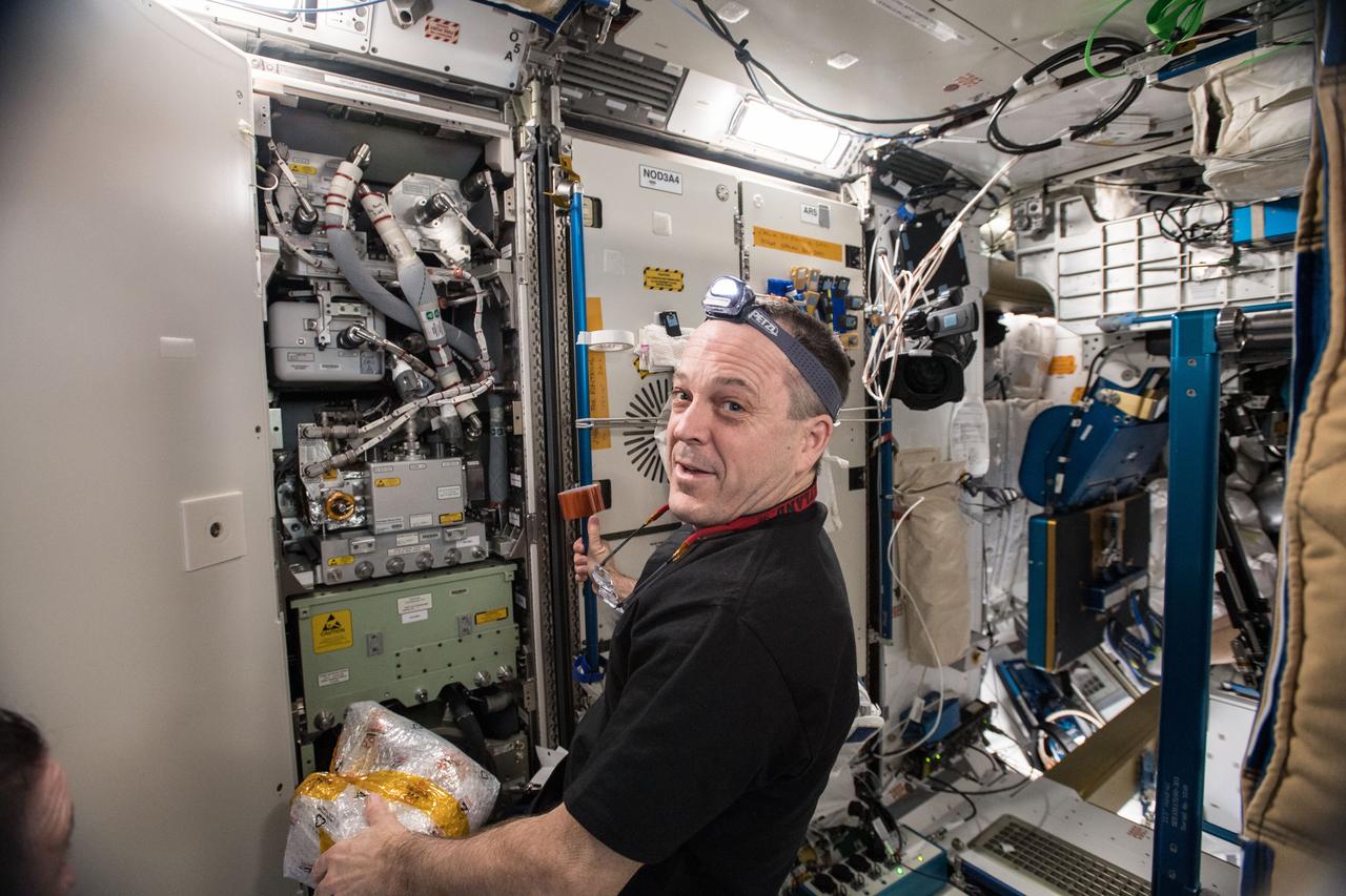
iss056e014487 (June 18, 2018) --- Expedition 56 Flight Engineer Ricky Arnold of NASA is pictured in the Unity module during life support maintenance work to remove and replace an Oxygen Generation System Hydrogen Sensor.
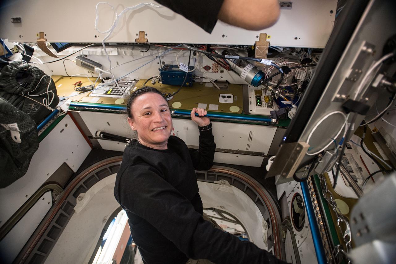
iss056e014502 (June 18, 2018) --- Expedition 56 Flight Engineer Serena Auñón-Chancellor of NASA is pictured in the Unity module during life support maintenance work to remove and replace an Oxygen Generation System Hydrogen Sensor.
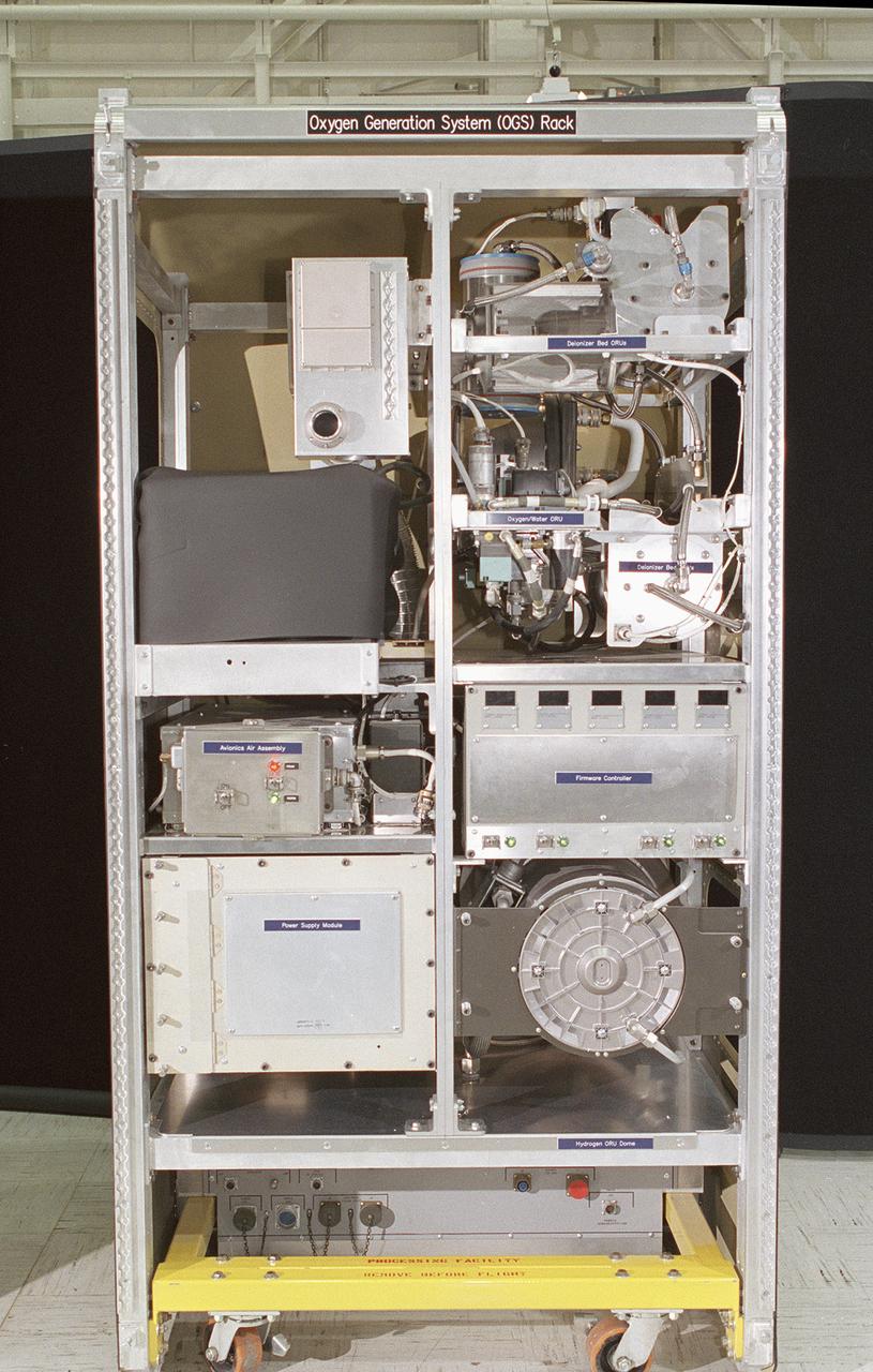
The Environmental Control and Life Support System (ECLSS) Group of the Flight Projects Directorate at the Marshall Space Flight Center (MSFC) in Huntsville, Alabama, is responsible for designing and building the life support systems that will provide the crew of the International Space Station (ISS) a comfortable environment in which to live and work. This is a close-up view of ECLSS Oxygen Generation System (OGS) rack. The ECLSS Group at the MSFC oversees the development of the OGS, which produces oxygen for breathing air for the crew and laboratory animals, as well as for replacing oxygen lost due to experiment use, airlock depressurization, module leakage, and carbon dioxide venting. The OGS consists primarily of the Oxygen Generator Assembly (OGA), provided by the prime contractor, the Hamilton Sundstrand Space Systems, International (HSSSI) in Windsor Locks, Cornecticut and a Power Supply Module (PSM), supplied by the MSFC. The OGA is comprised of a cell stack that electrolyzes (breaks apart the hydrogen and oxygen molecules) some of the clean water provided by the Water Recovery System and the separators that remove the gases from water after electrolysis. The PSM provides the high power to the OGA needed to electrolyze the water.
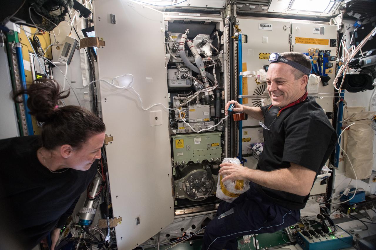
iss056e014488 (June 18, 2018) --- Expedition 56 Flight Engineers Serena Auñón-Chancellor (right) and Ricky Arnold of NASA are pictured in the Unity module during life support maintenance work to remove and replace an Oxygen Generation System Hydrogen Sensor.
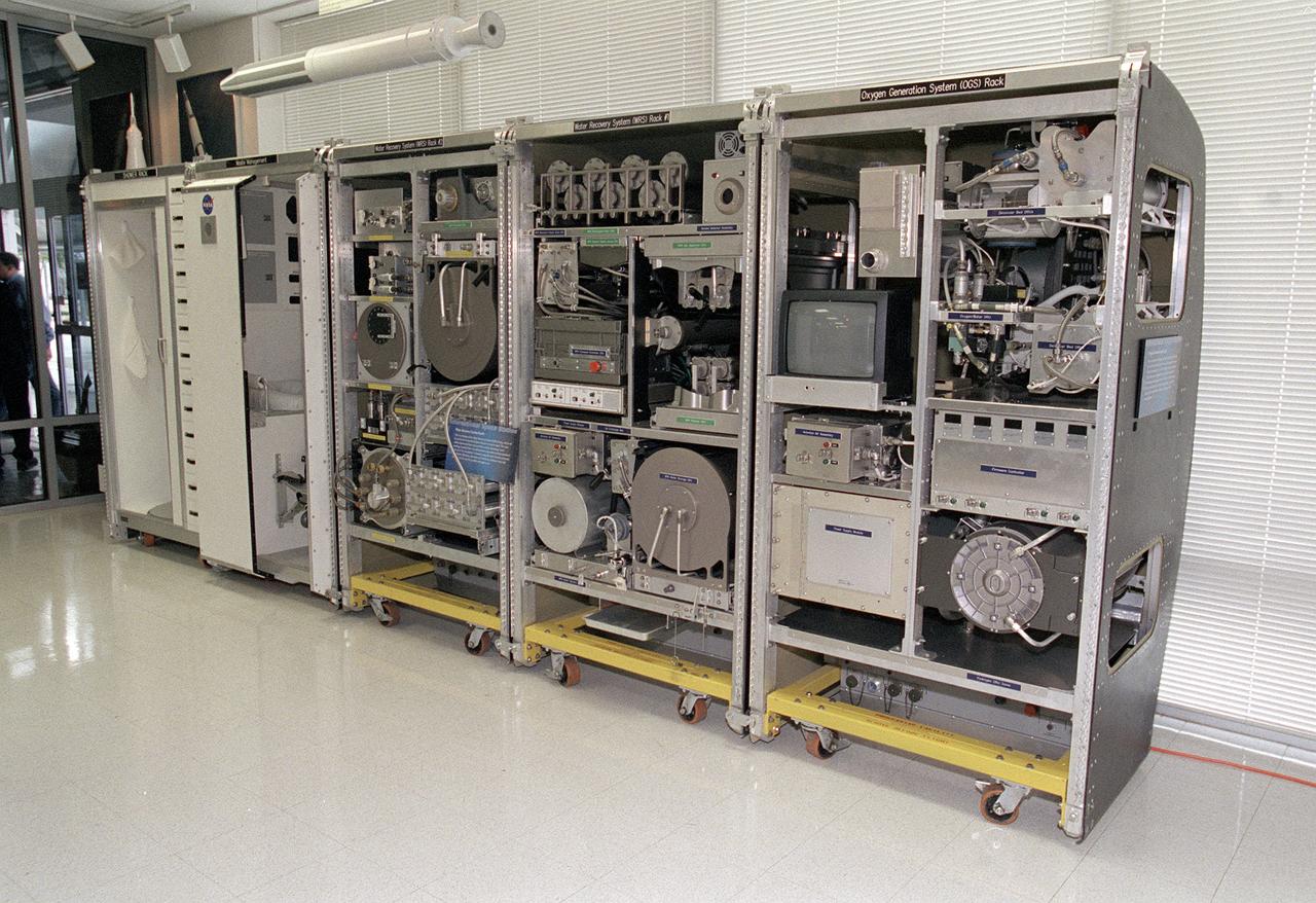
The Environmental Control and Life Support System (ECLSS) Group of the Flight Projects Directorate at the Marshall Space Flight Center in Huntsville, Alabama, is responsible for designing and building the life support systems that will provide the crew of the International Space Station (ISS) a comfortable environment in which to live and work. This photograph shows the mockup of the the ECLSS to be installed in the Node 3 module of the ISS. From left to right, shower rack, waste management rack, Water Recovery System (WRS) Rack #2, WRS Rack #1, and Oxygen Generation System (OGS) rack are shown. The WRS provides clean water through the reclamation of wastewaters and is comprised of a Urine Processor Assembly (UPA) and a Water Processor Assembly (WPA). The UPA accepts and processes pretreated crewmember urine to allow it to be processed along with other wastewaters in the WPA. The WPA removes free gas, organic, and nonorganic constituents before the water goes through a series of multifiltration beds for further purification. The OGS produces oxygen for breathing air for the crew and laboratory animals, as well as for replacing oxygen loss. The OGS is comprised of a cell stack, which electrolyzes (breaks apart the hydrogen and oxygen molecules) some of the clean water provided by the WRS, and the separators that remove the gases from the water after electrolysis.
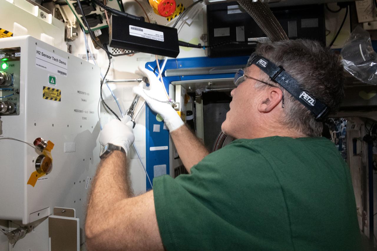
iss069e008416 (May 2, 2023) --- NASA astronaut and Expedition 69 Flight Engineer Stephen Bowen installs the Advanced Hydrogen Sensor Technology Demonstration (OGA H2 Sensor Demo) on the Destiny laboratory module's Oxygen Generation System rack aboard the International Space Station. The device is testing new sensors to promote a longer operational life inside advanced oxygen generation systems for future space exploration missions.
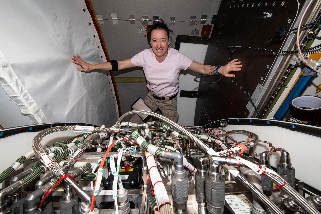
iss066e003338 (Oct. 20, 2021) --- NASA astronaut and Expedition 66 Flight Engineer Megan McArthur replaces components and flushes contaminants inside the Tranquility module's U.S. oxygen generation system.
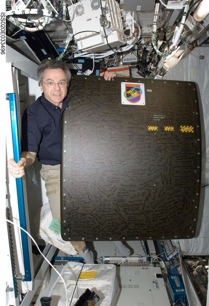
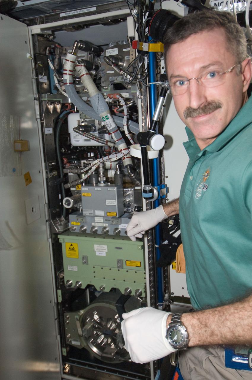
ISS020-E-033496 (21 Aug. 2009) --- Canadian Space Agency astronaut Robert Thirsk, Expedition 20 flight engineer, is pictured with the oxygen generator system (OGS) rack cover in the Destiny laboratory of the International Space Station.
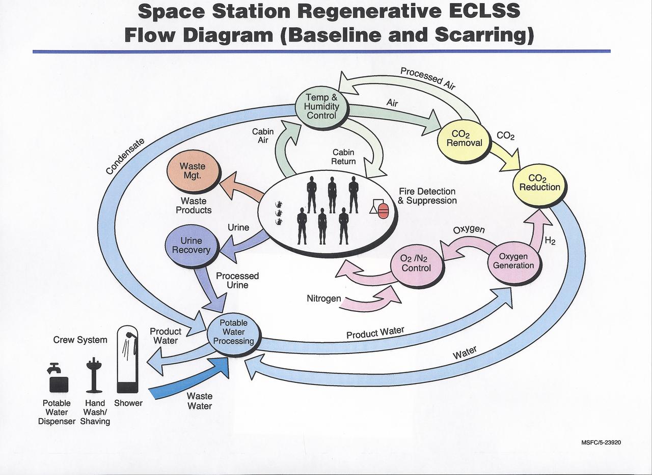
This diagram shows the flow of recyclable resources in the International Space Station (ISS). The Environmental Control and Life Support System (ECLSS) Group of the Flight Projects Directorate at the Marshall Space Flight Center is responsible for the regenerative ECLSS hardware, as well as providing technical support for the rest of the system. The regenerative ECLSS, whose main components are the Water Recovery System (WRS), and the Oxygen Generation System (OGS), reclaims and recycles water and oxygen. The ECLSS maintains a pressurized habitation environment, provides water recovery and storage, maintains and provides fire detection / suppression, and provides breathable air and a comfortable atmosphere in which to live and work within the ISS. The ECLSS hardware will be located in the Node 3 module of the ISS.
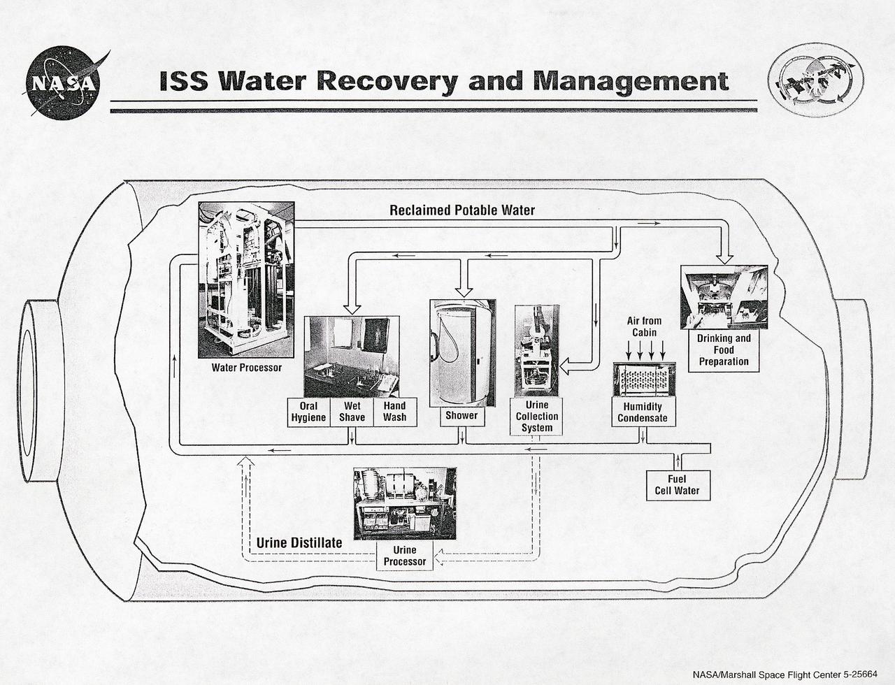
This diagram shows the flow of water recovery and management in the International Space Station (ISS). The Environmental Control and Life Support System (ECLSS) Group of the Flight Projects Directorate at the Marshall Space Flight Center is responsible for the regenerative ECLSS hardware, as well as providing technical support for the rest of the system. The regenerative ECLSS, whose main components are the Water Recovery System (WRS), and the Oxygen Generation System (OGS), reclaims and recycles water oxygen. The ECLSS maintains a pressurized habitation environment, provides water recovery and storage, maintains and provides fire detection/ suppression, and provides breathable air and a comfortable atmosphere in which to live and work within the ISS. The ECLSS hardware will be located in the Node 3 module of the ISS.
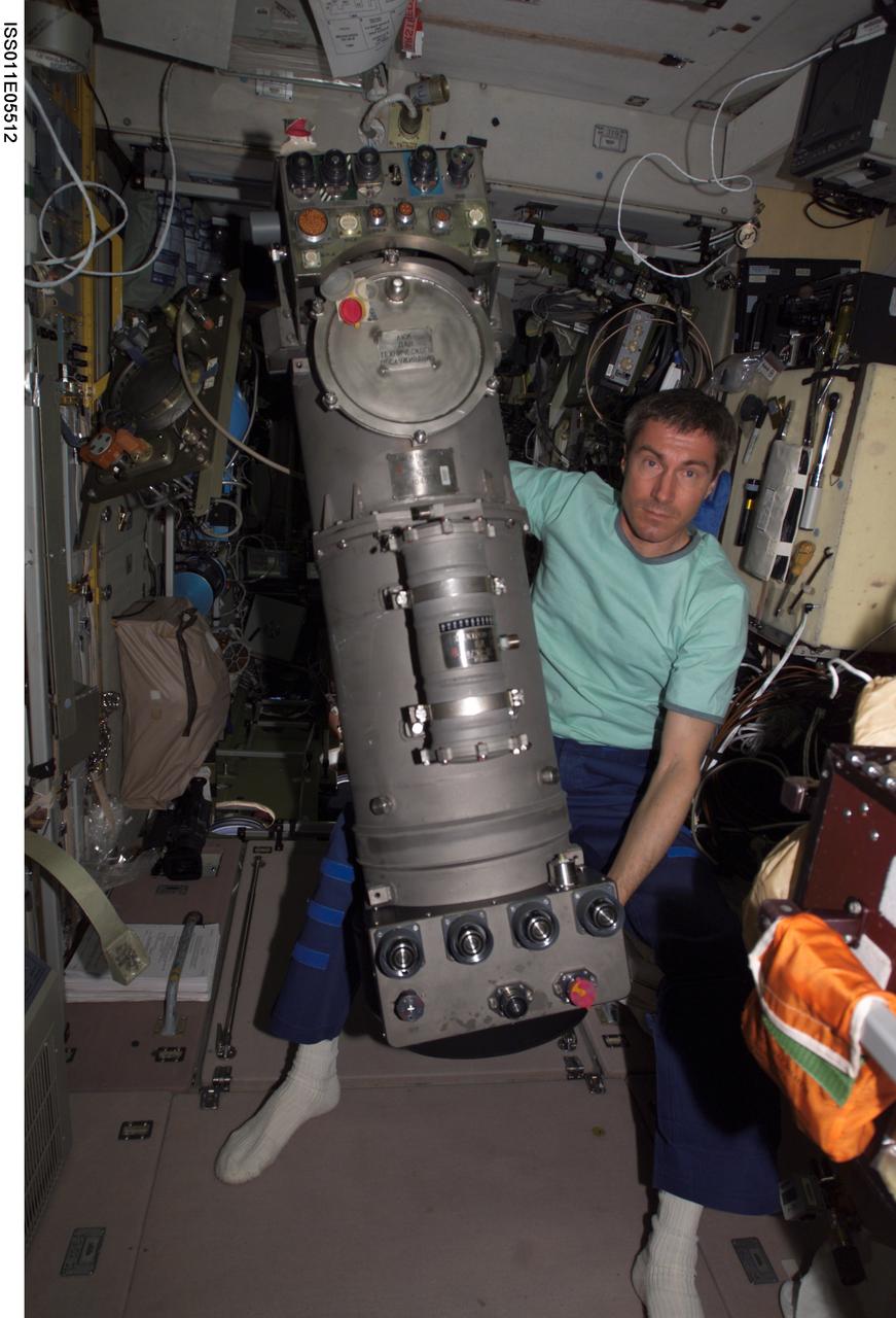
ISS011-E-05512 (5 May 2005) --- Cosmonaut Sergei K. Krikalev, Expedition 11 commander representing Russia's Federal Space Agency, working on the Elektron oxygen-generation system in the Zvezda Service Module that has worked intermittently aboard the International Space Station (ISS).
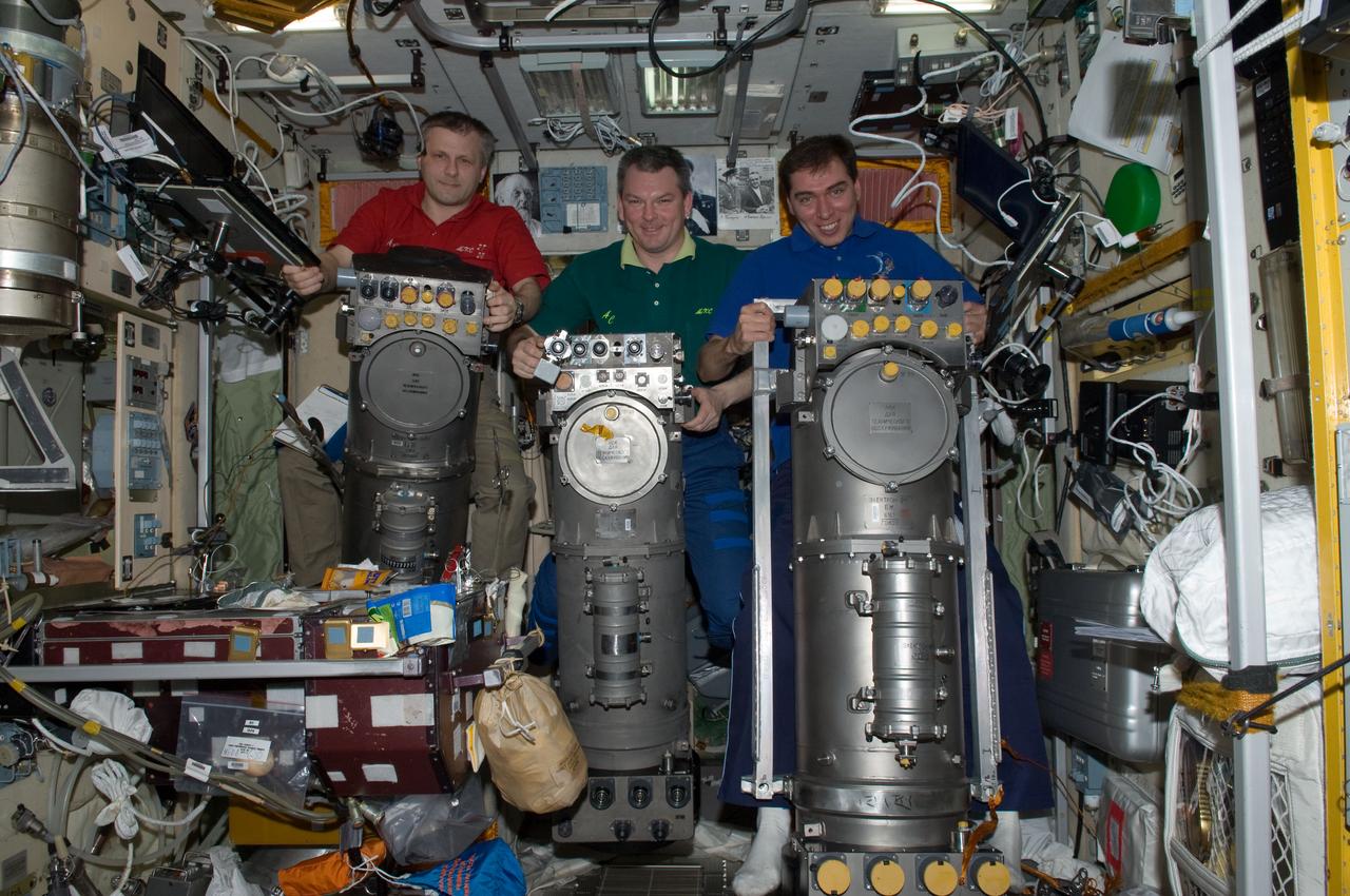
ISS028-E-014908 (8 July 2011) --- Russian cosmonauts Andrey Borisenko (left), Expedition 28 commander; Alexander Samokutyaev (center) and Sergei Volkov, both flight engineers, are pictured with Russian Elektron oxygen generator systems in the Zvezda Service Module of the International Space Station.
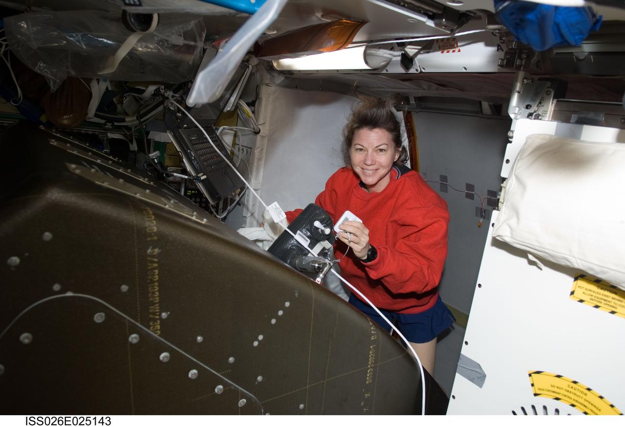
ISS026-E-025143 (8 Feb. 2011) --- NASA astronaut Catherine (Cady) Coleman, Expedition 26 flight engineer, works at the Atmosphere Revitalization / Oxygen Generation System (AR OGS) rack in the Harmony node of the International Space Station. Coleman collected recirculation loop samples for subsequent analysis for pH value.

ISS011-E-08465 (9 June 2005) --- Cosmonaut Sergei K. Krikalev, Expedition 11 commander representing Russia's Federal Space Agency, works on the Elektron oxygen-generation system in the Zvezda Service Module on the International Space Station (ISS).
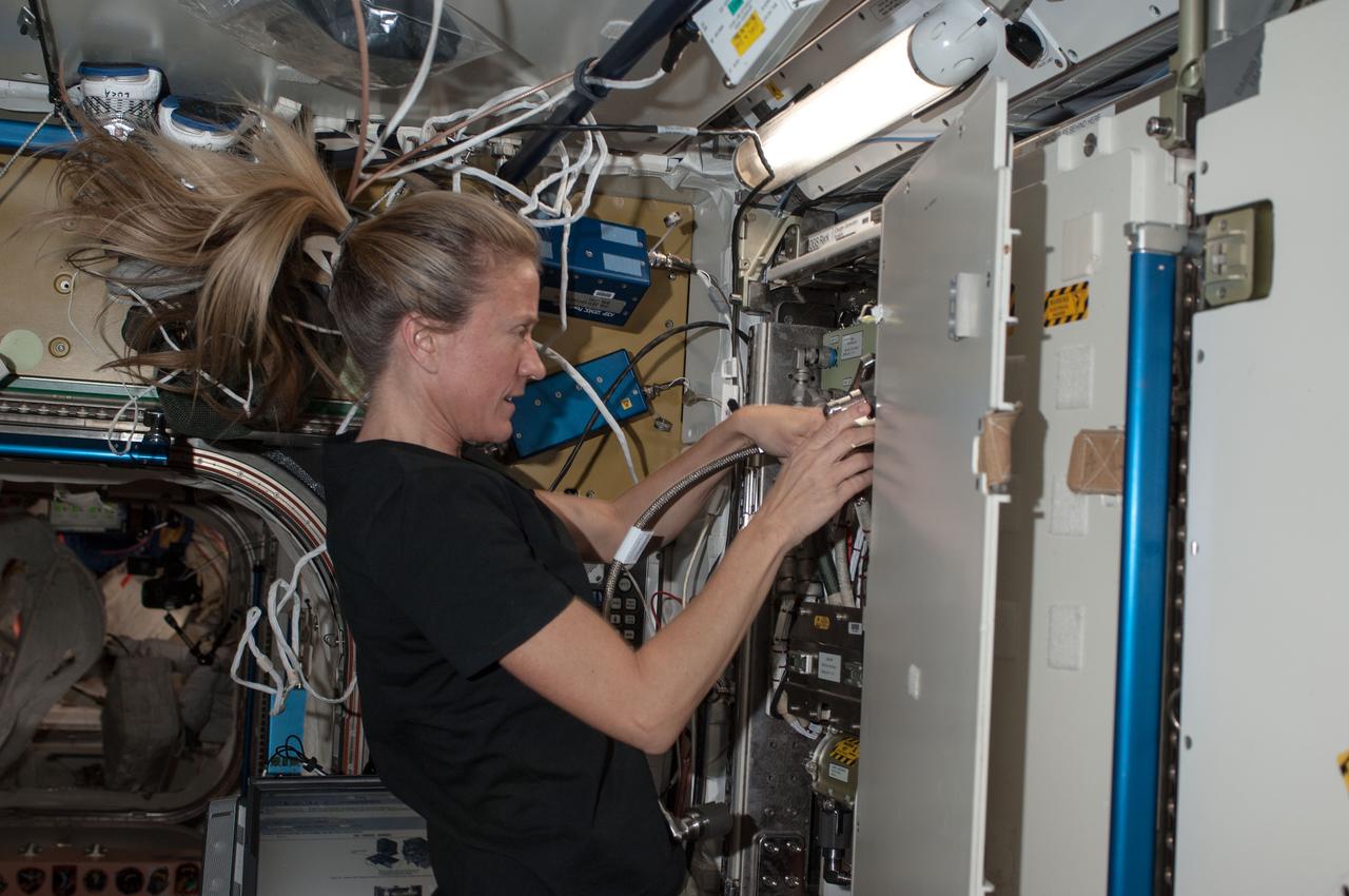
ISS036-E-021797 (18 July 2013) --- NASA astronaut Karen Nyberg, Expedition 36 flight engineer, performs a remove and replace of the Oxygen Generation System (OGS) Hydrogen (H2) Sensor in the Tranquility node of the International Space Station.
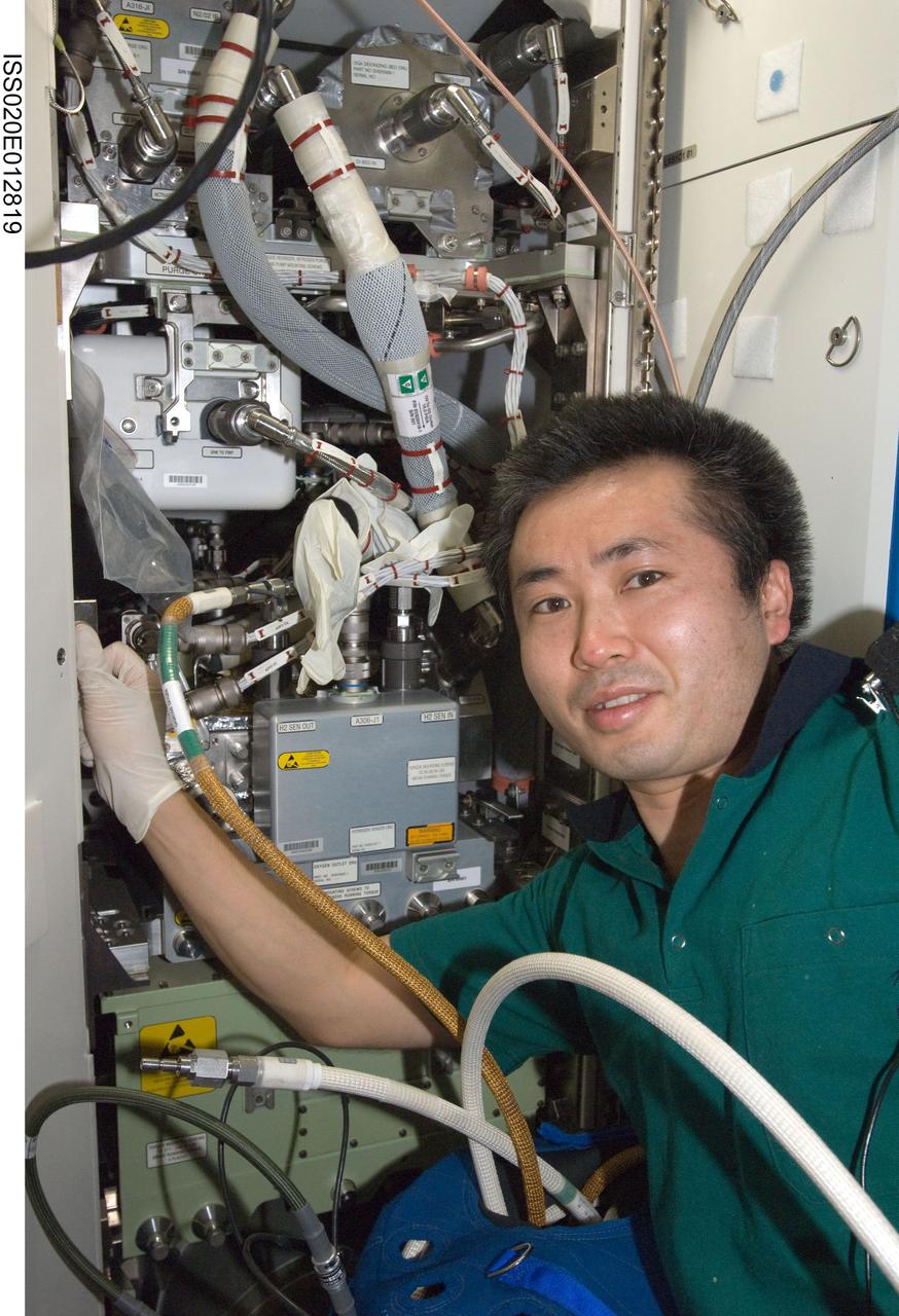
ISS020-E-012819 (22 June 2009) --- Japan Aerospace Exploration Agency (JAXA) astronaut Koichi Wakata, Expedition 20 flight engineer, performs in-flight maintenance on the Oxygen Generator System (OGS) in the Destiny laboratory of the International Space Station.
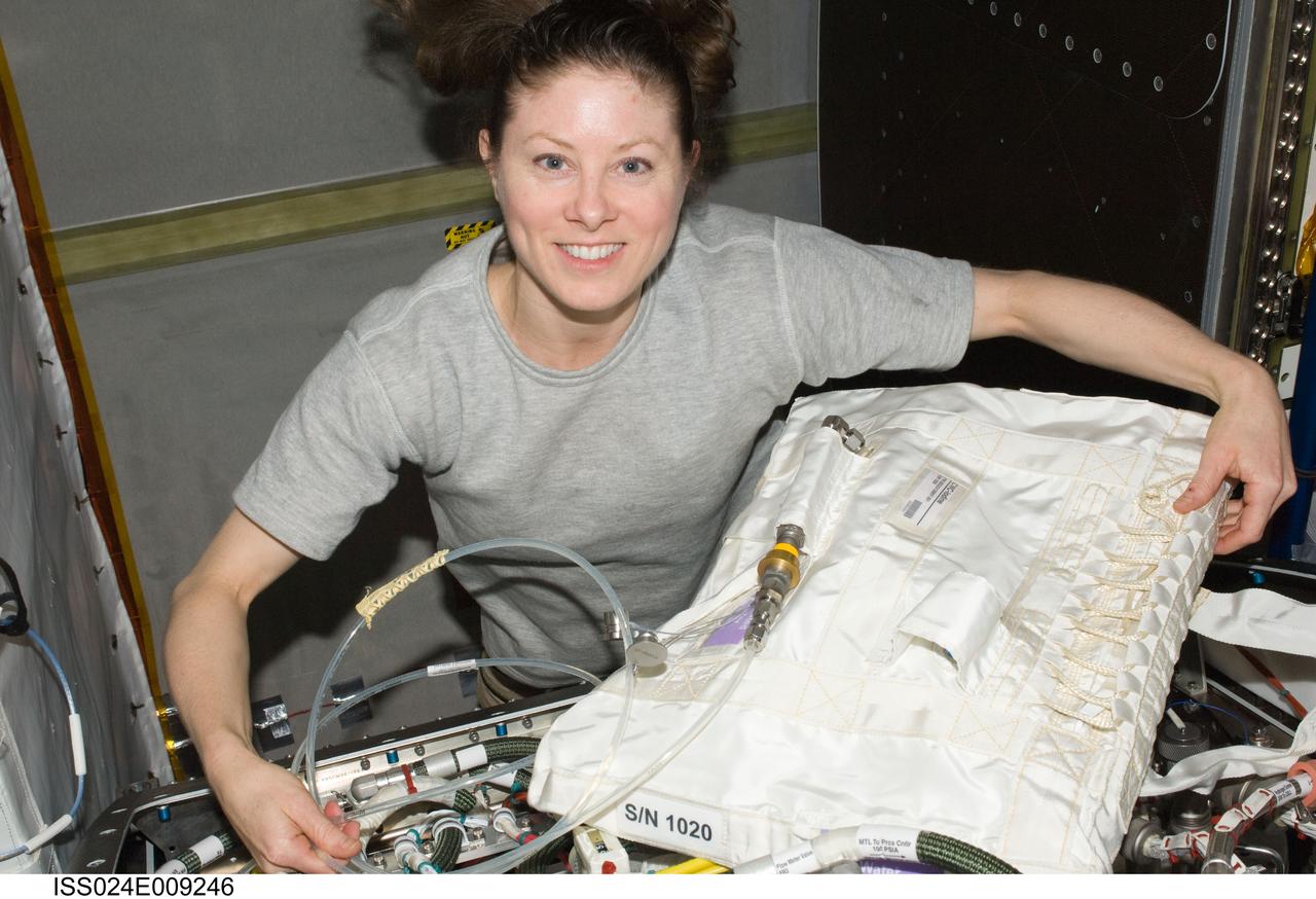
ISS024-E-009246 (21 July 2010) --- NASA astronaut Tracy Caldwell Dyson, Expedition 24 flight engineer, is pictured during troubleshooting operations of the Oxygen Generator System (OGS) hardware and replacement of an H2 (hydrogen) Dome Orbit Replaceable Unit (ORU) in the Destiny laboratory of the International Space Station.
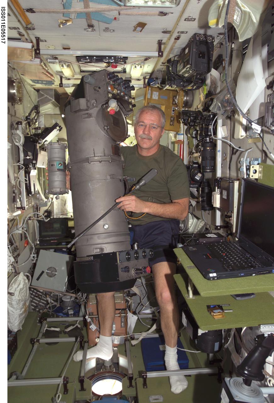
ISS011-E-05517 (5 May 2005) --- Astronaut John L. Phillips, Expedition 11 NASA ISS science officer and flight engineer, working on the Elektron oxygen-generation system in the Zvezda Service Module that has worked intermittently aboard the International Space Station (ISS).
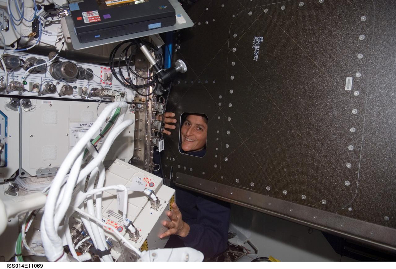
ISS014-E-11069 (3 Jan. 2007) --- Astronaut Sunita L. Williams, Expedition 14 flight engineer, looks through an opening during the Oxygen Generator System (OGS) rack rotation in the Destiny laboratory of the International Space Station.
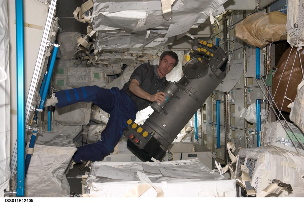
ISS011-E-12405 (31 July 2005) --- Cosmonaut Sergei K. Krikalev, Expedition 11 commander representing Russia's Federal Space Agency, holds the Elektron oxygen-generation system in the Italian-built Raffaello Multi-Purpose Logistics Module (MPLM) docked to the International Space Station during the STS-114 mission.

ISS011-E-05518 (5 May 2005) --- Cosmonaut Sergei K. Krikalev, Expedition 11 commander representing Russia's Federal Space Agency, working on the Elektron oxygen-generation system in the Zvezda Service Module that has worked intermittently aboard the International Space Station (ISS).
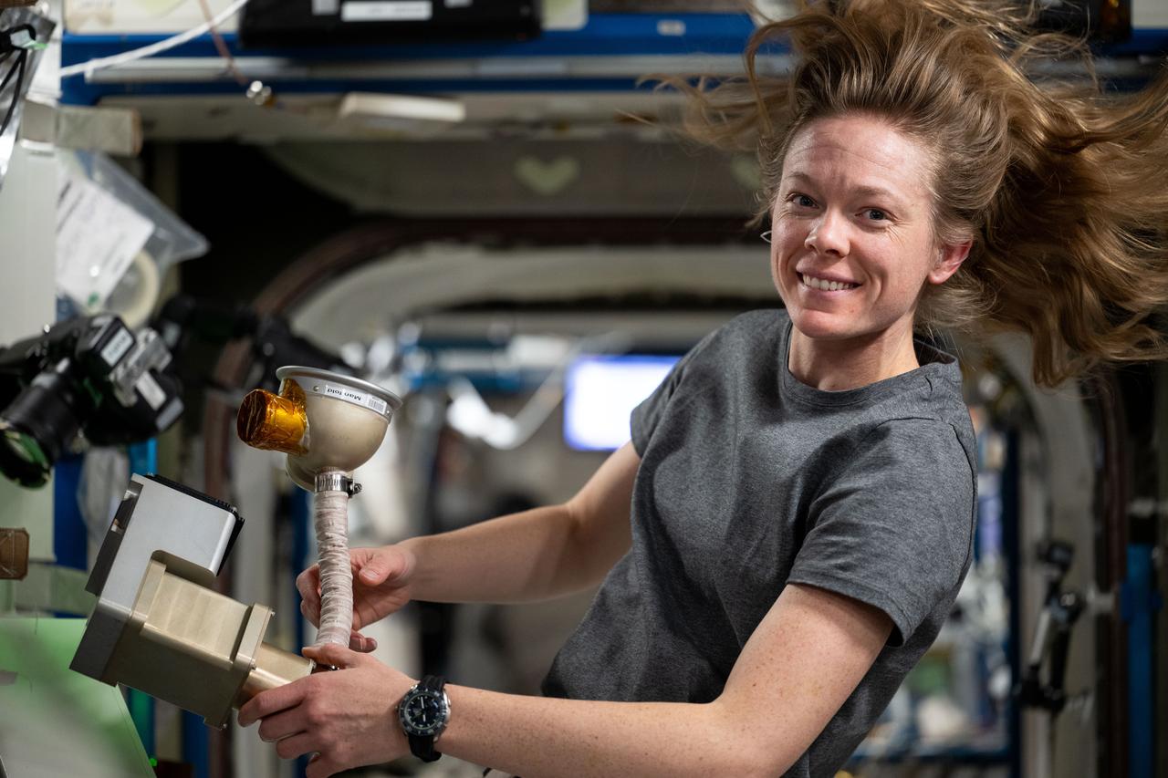
iss073e0118757 (May 29, 2025) --- NASA astronaut and Expedition 73 Flight Engineer Nichole Ayers cleans and services life support components that are part of the Oxygen Generation System rack located inside the International Space Station's Destiny laboratory module.
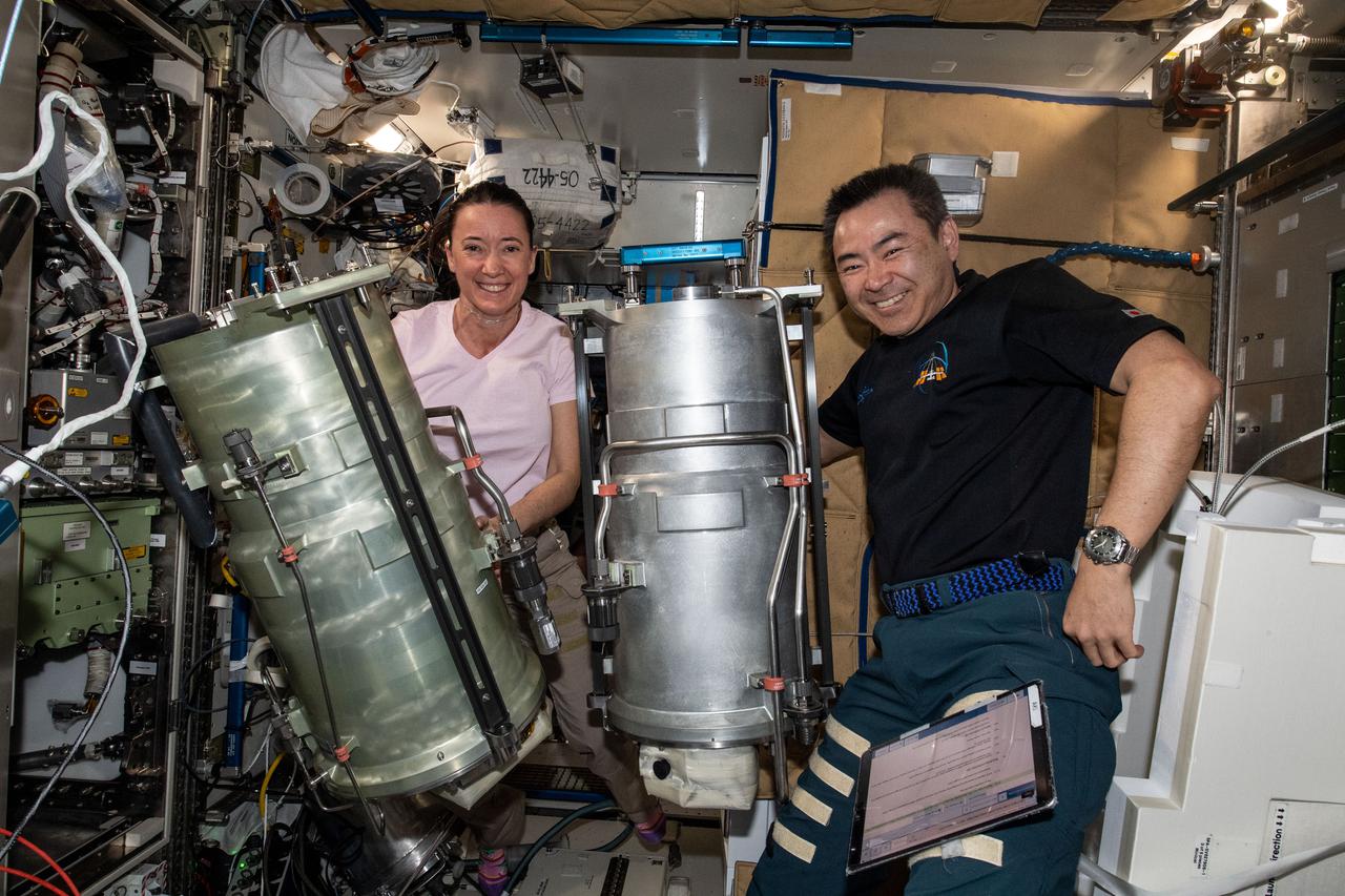
iss066e003308 (Oct. 20, 2021) --- Expedition 66 Flight Engineers Megan McArthur of NASA and Akihiko Hoshide of the Japan Aerospace Exploration Agency (JAXA) replace components and flush contaminants inside the Tranquility module's U.S. oxygen generation system.
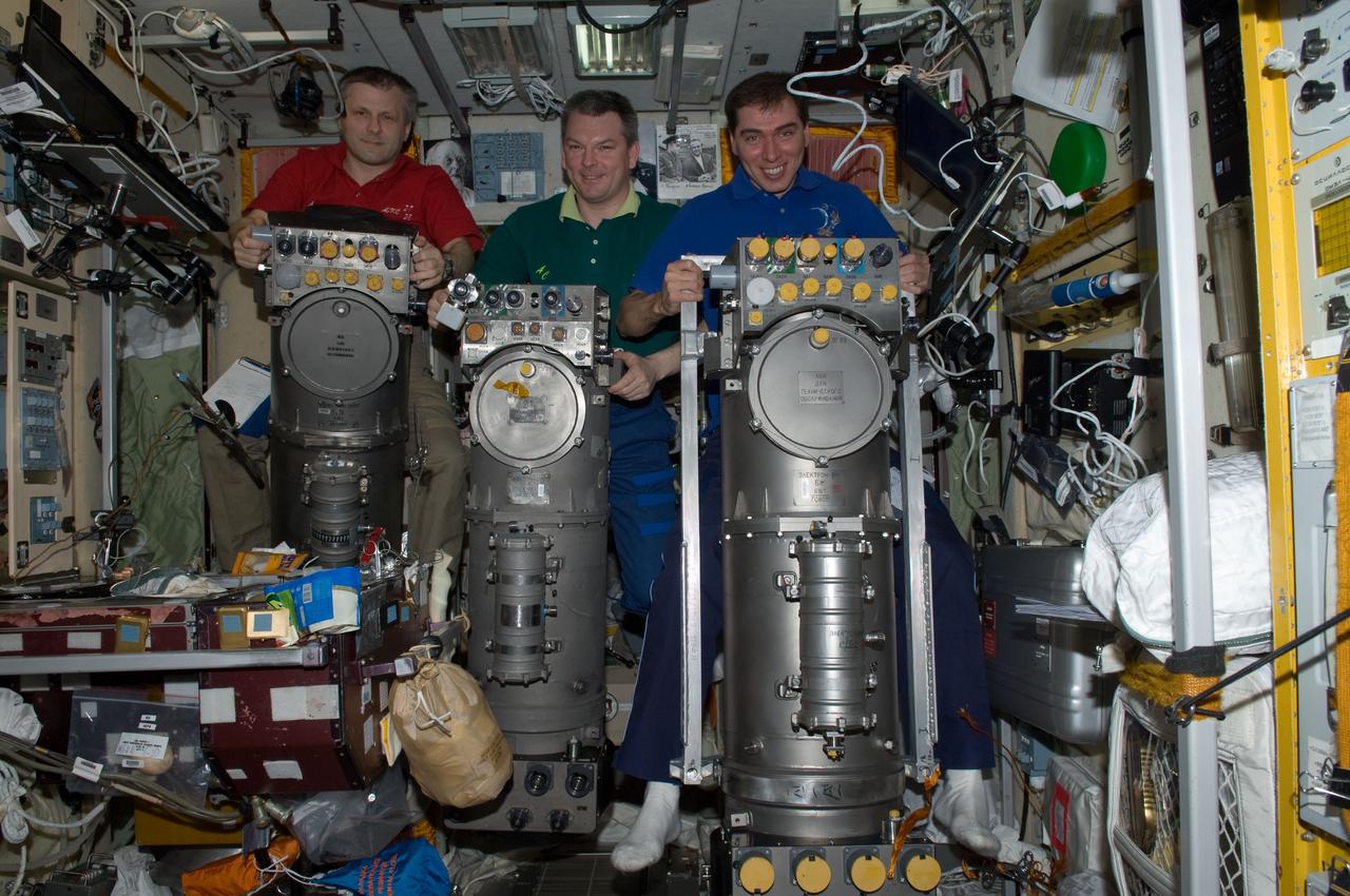
ISS028-E-014909 (8 July 2011) --- Russian cosmonauts Andrey Borisenko (left), Expedition 28 commander; Alexander Samokutyaev (center) and Sergei Volkov, both flight engineers, are pictured with Russian Elektron oxygen generator systems in the Zvezda Service Module of the International Space Station.
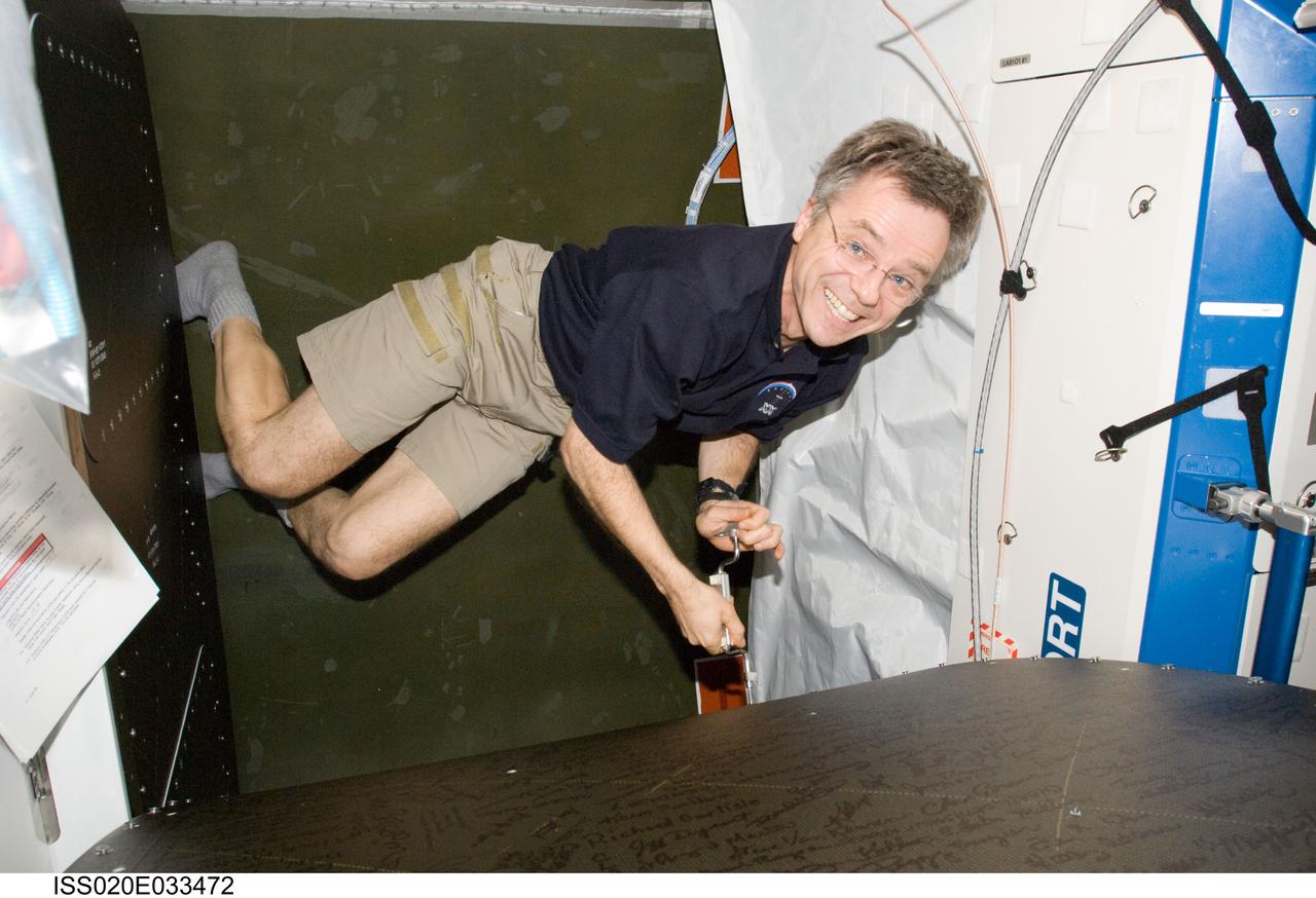
ISS020-E-033472 (21 Aug. 2009) --- Canadian Space Agency astronaut Robert Thirsk, Expedition 20 flight engineer, prepares to perform in-flight maintenance (IFM) on the oxygen generator system (OGS) rack in the Destiny laboratory of the International Space Station.
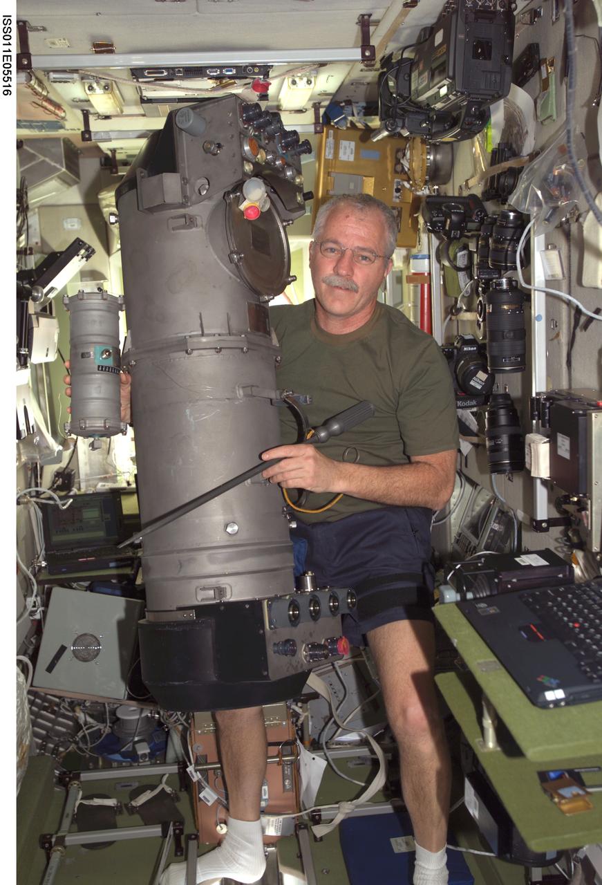
ISS011-E-05516 (5 May 2005) --- Astronaut John L. Phillips, Expedition 11 NASA ISS science officer and flight engineer, working on the Elektron oxygen-generation system in the Zvezda Service Module that has worked intermittently aboard the International Space Station (ISS).

ISS026-E-025142 (8 Feb. 2011) --- NASA astronaut Catherine (Cady) Coleman, Expedition 26 flight engineer, works at the Atmosphere Revitalization / Oxygen Generation System (AR OGS) rack in the Harmony node of the International Space Station. Coleman collected recirculation loop samples for subsequent analysis for pH value.
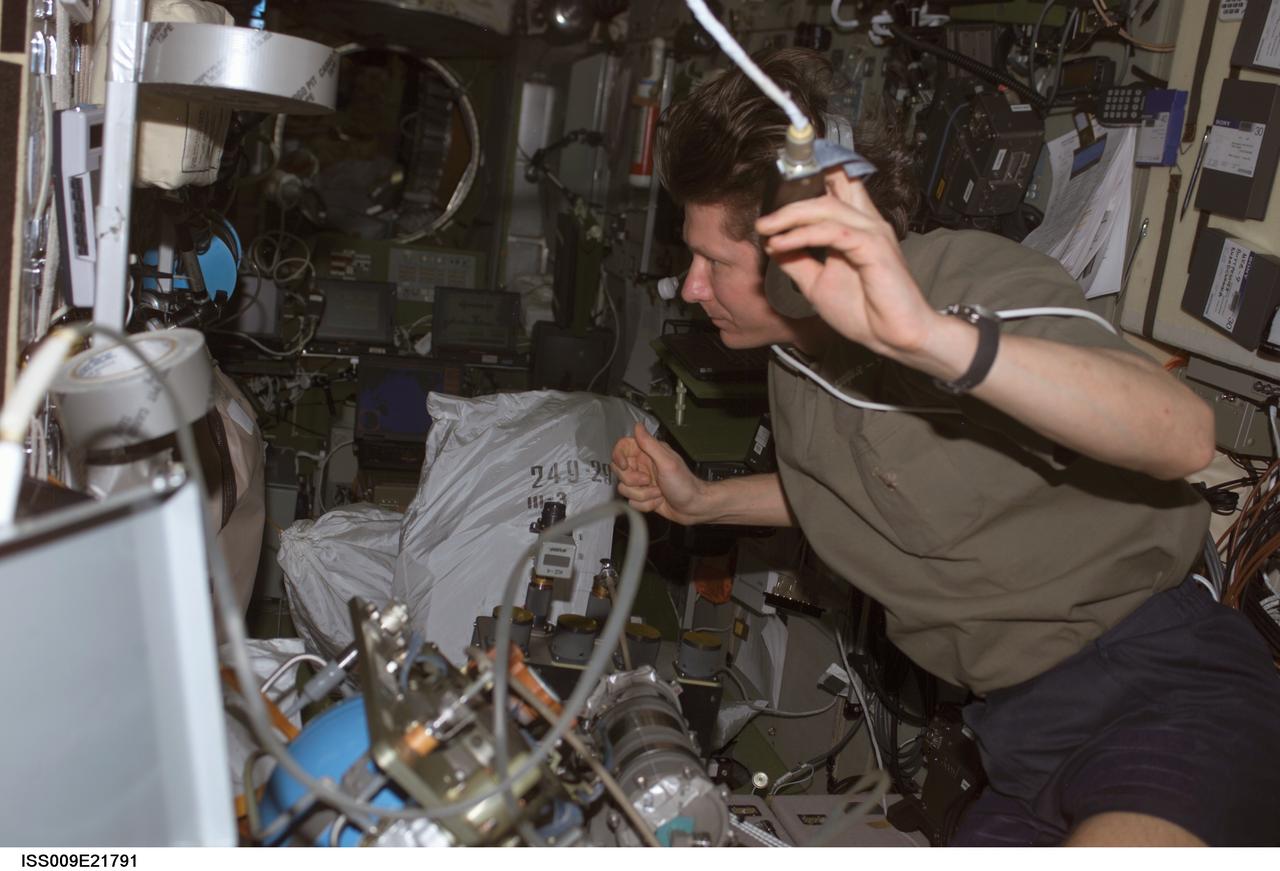
ISS009-E-21791 (8 September 2004) --- Cosmonaut Gennady I. Padalka, Expedition 9 commander representing Russia's Federal Space Agency, performs maintenance on a spare version of a part connected to the Russian Elektron oxygen generation system in the Zvezda Service Module of the International Space Station (ISS).
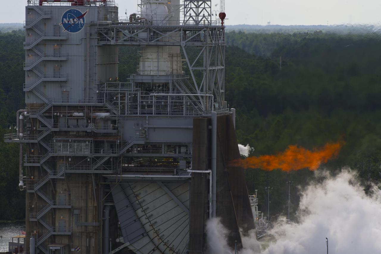
NASA conducted a long-duration test of the J-2X powerpack, 1,261 seconds total, on the A-1 Test Stand at Stennis Space Center on Aug. 16, marking another step in development of the next-generation rocket engine. The powerpack is a system of components on the top portion of the J-2X engine, including the gas generator, oxygen and fuel turbopumps, and related ducts and valves.
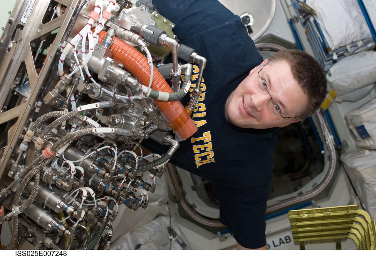
ISS025-E-007248 (13 Oct. 2010) --- In the Tranquility node aboard the International Space Station, NASA astronaut Doug Wheelock, Expedition 25 commander, works to install the new Sabatier system that will extract more water out of the ISS atmosphere. Sabatier will create water from the byproducts of the station?s Oxygen Generation System and Carbon Dioxide Removal Assembly. Under contract to NASA, Hamilton Sundstrand supplied the flight hardware and operational support for a Sabatier-reaction based system that operates as part of the station?s Environmental Control and Life Support System.
ISS030-E-236919 (18 April 2012) --- NASA astronaut Dan Burbank, Expedition 30 commander, works with the Oxygen Generator System (OGS) rack in the Tranquility node of the International Space Station. Burbank unpowered the OGS, purged the hydrogen sensor Orbital Replacement Unit (ORU) with the Hydrogen Sensor ORU Purge Adapter (HOPA) for return to Earth, and replaced the hydrogen sensor with a new spare, then cleaned the rack Avionics Air Assembly (AAA).
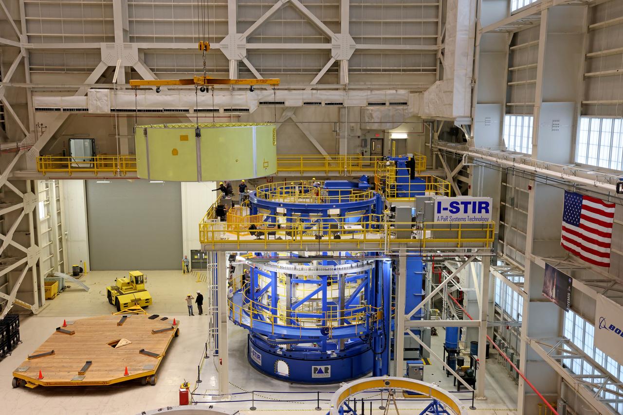
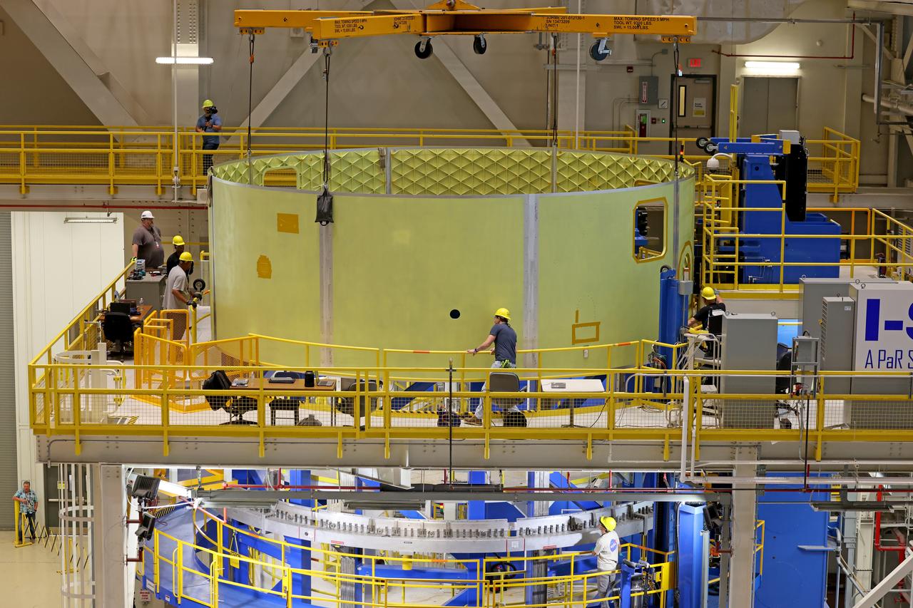
Crews at NASA’s Michoud Assembly Facility in New Orleans lift the forward skirt of a core stage that will power NASA’s Space Launch System (SLS) rocket out of the Vertical Weld Center Sept. 16, 2022. The forward skirt will be used for NASA’s Artemis IV mission. The hardware houses flight computers, cameras, and avionics systems for the SLS rocket. The SLS core stage is made up of five unique elements: the forward skirt, liquid oxygen tank, intertank, liquid hydrogen tank, and the engine section. When fully stacked, the forward skirt is located at the top of the 212-foot-tall core stage and connects to the upper part of the rocket. The core stage and its four RS-25 engines provide more than 2 million pounds of thrust to help power NASA’s next-generation lunar missions. Image credit: NASA/Michael DeMocker

Crews at NASA’s Michoud Assembly Facility in New Orleans lift the forward skirt of a core stage that will power NASA’s Space Launch System (SLS) rocket out of the Vertical Weld Center Sept. 16, 2022. The forward skirt will be used for NASA’s Artemis IV mission. The hardware houses flight computers, cameras, and avionics systems for the SLS rocket. The SLS core stage is made up of five unique elements: the forward skirt, liquid oxygen tank, intertank, liquid hydrogen tank, and the engine section. When fully stacked, the forward skirt is located at the top of the 212-foot-tall core stage and connects to the upper part of the rocket. The core stage and its four RS-25 engines provide more than 2 million pounds of thrust to help power NASA’s next-generation lunar missions. Image credit: NASA/Michael DeMocker
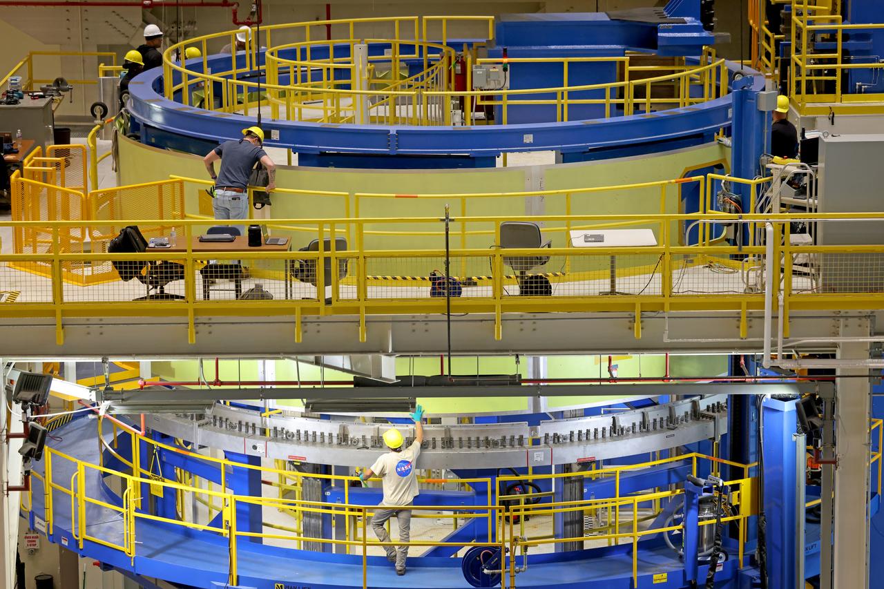
Crews at NASA’s Michoud Assembly Facility in New Orleans lift the forward skirt of a core stage that will power NASA’s Space Launch System (SLS) rocket out of the Vertical Weld Center Sept. 16, 2022. The forward skirt will be used for NASA’s Artemis IV mission. The hardware houses flight computers, cameras, and avionics systems for the SLS rocket. The SLS core stage is made up of five unique elements: the forward skirt, liquid oxygen tank, intertank, liquid hydrogen tank, and the engine section. When fully stacked, the forward skirt is located at the top of the 212-foot-tall core stage and connects to the upper part of the rocket. The core stage and its four RS-25 engines provide more than 2 million pounds of thrust to help power NASA’s next-generation lunar missions. Image credit: NASA/Michael DeMocker
Crews at NASA’s Michoud Assembly Facility in New Orleans lift the forward skirt of a core stage that will power NASA’s Space Launch System (SLS) rocket out of the Vertical Weld Center Sept. 16, 2022. The forward skirt will be used for NASA’s Artemis IV mission. The hardware houses flight computers, cameras, and avionics systems for the SLS rocket. The SLS core stage is made up of five unique elements: the forward skirt, liquid oxygen tank, intertank, liquid hydrogen tank, and the engine section. When fully stacked, the forward skirt is located at the top of the 212-foot-tall core stage and connects to the upper part of the rocket. The core stage and its four RS-25 engines provide more than 2 million pounds of thrust to help power NASA’s next-generation lunar missions. Image credit: NASA/Michael DeMocker
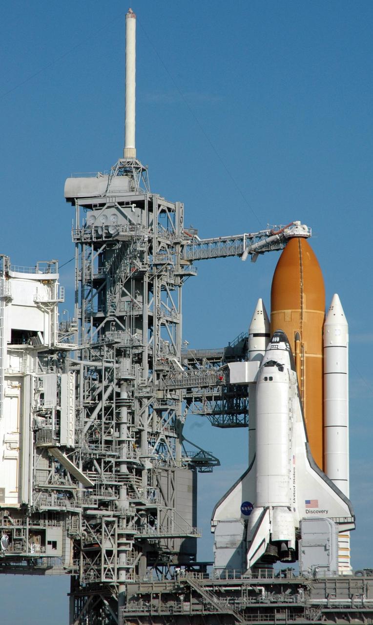
KENNEDY SPACE CENTER, FLA. -- Under a clear blue sky, Space Shuttle Discovery is ready for launch of mission STS-116 from Launch Pad 39B. Atop the fixed service structure at left looms the 80-foot-high lightning mast, part of the lightning protection system on the pad. Beneath Discovery's wings are the tail masts, which provide several umbilical connections to the orbiter, including a liquid-oxygen line through one and a liquid-hydrogen line through another. Seen above the golden external tank is the vent hood (known as the "beanie cap") at the end of the gaseous oxygen vent arm, extending from the FSS. Vapors are created as the liquid oxygen in the external tank boil off. The hood vents the gaseous oxygen vapors away from the space shuttle vehicle. Below it, also extending toward Discovery from the FSS, is the orbiter access arm with the White Room at the end. The crew gains access into the orbiter through the White Room. Discovery is scheduled to launch on mission STS-116 at 9:35 p.m. today. On the mission, the crew will deliver truss segment, P5, to the International Space Station and begin the intricate process of reconfiguring and redistributing the power generated by two pairs of U.S. solar arrays. The P5 will be mated to the P4 truss that was delivered and attached during the STS-115 mission in September. Photo credit: NASA/Ken Thornsley
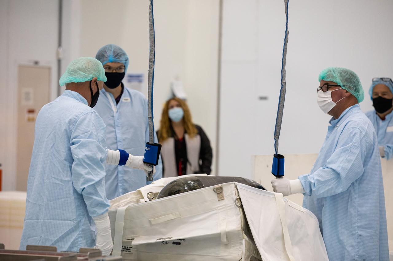
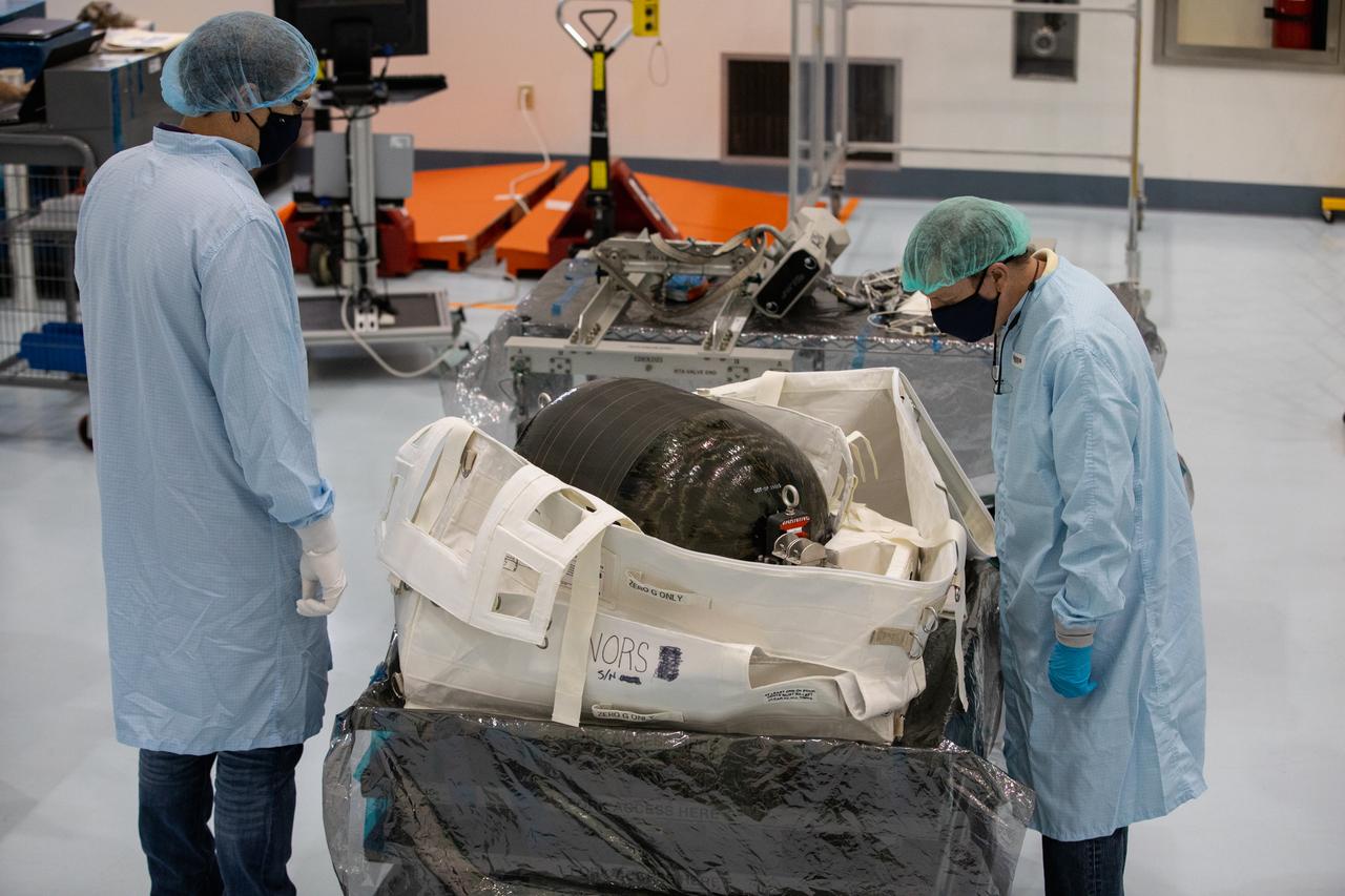
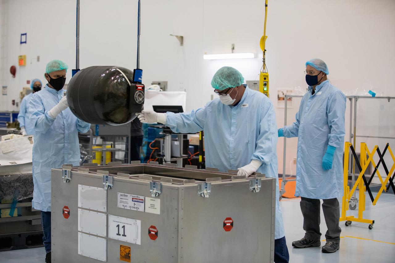
Technicians prepare to unpack and inspect a Nitrogen/Oxygen Recharge System (NORS) tank inside the Space Station Processing Facility high bay at NASA’s Kennedy Space Center in Florida on July 16, 2020. The NORS tanks and their support fixtures are designed to connect to the International Space Station’s existing air supply network to refill the previous generation of tanks installed during construction of the space station. These reusable tanks measure 3 feet long and 21 inches in diameter, and weigh about 200 pounds when filled. Once onboard, the tanks will be used to fill the oxygen and nitrogen tanks that supply the needed gases to the space station’s airlock for spacewalks. They could also be used to replenish the atmosphere inside the station. The NORS tanks will launch to the station later in the year on a commercial resupply mission.
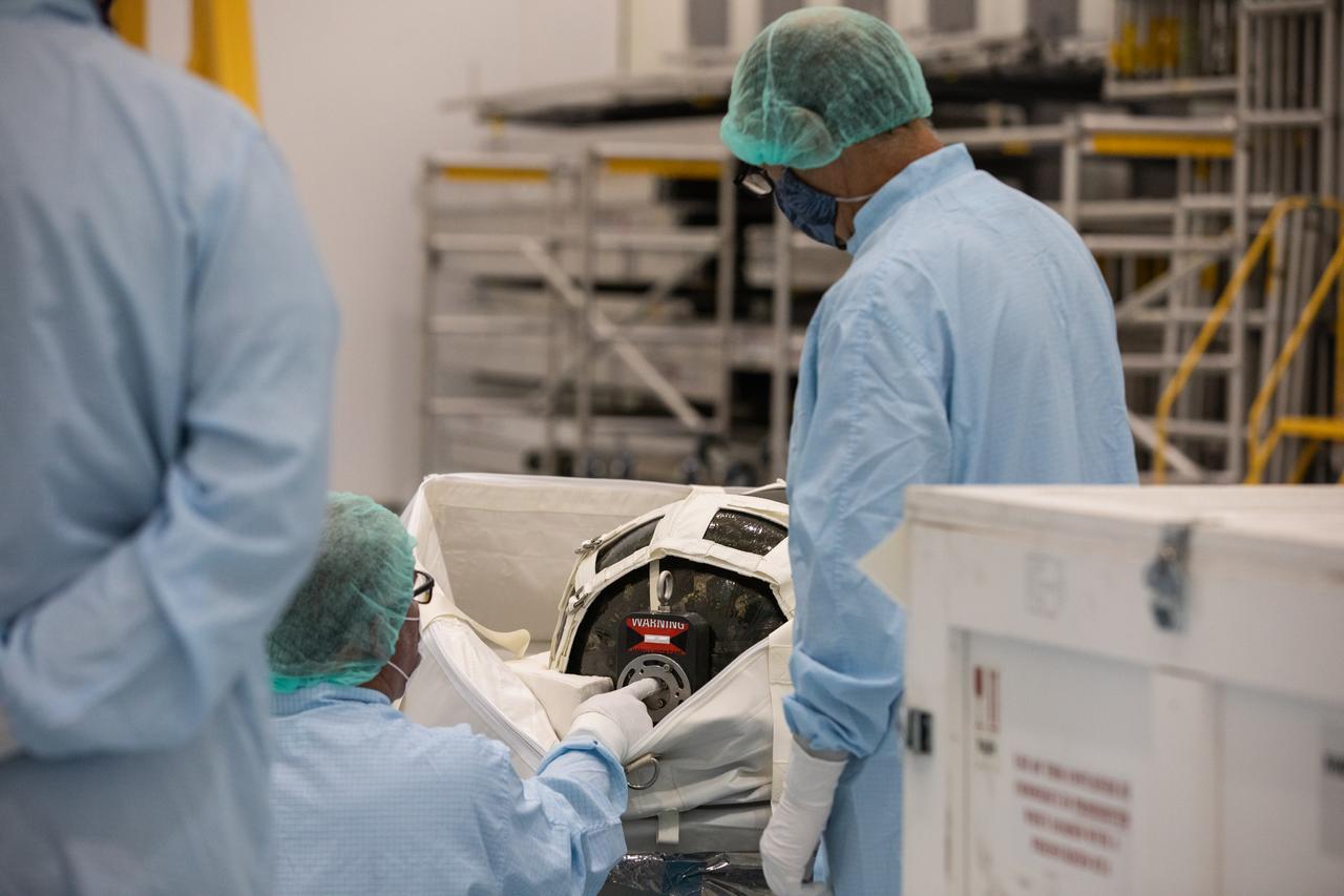
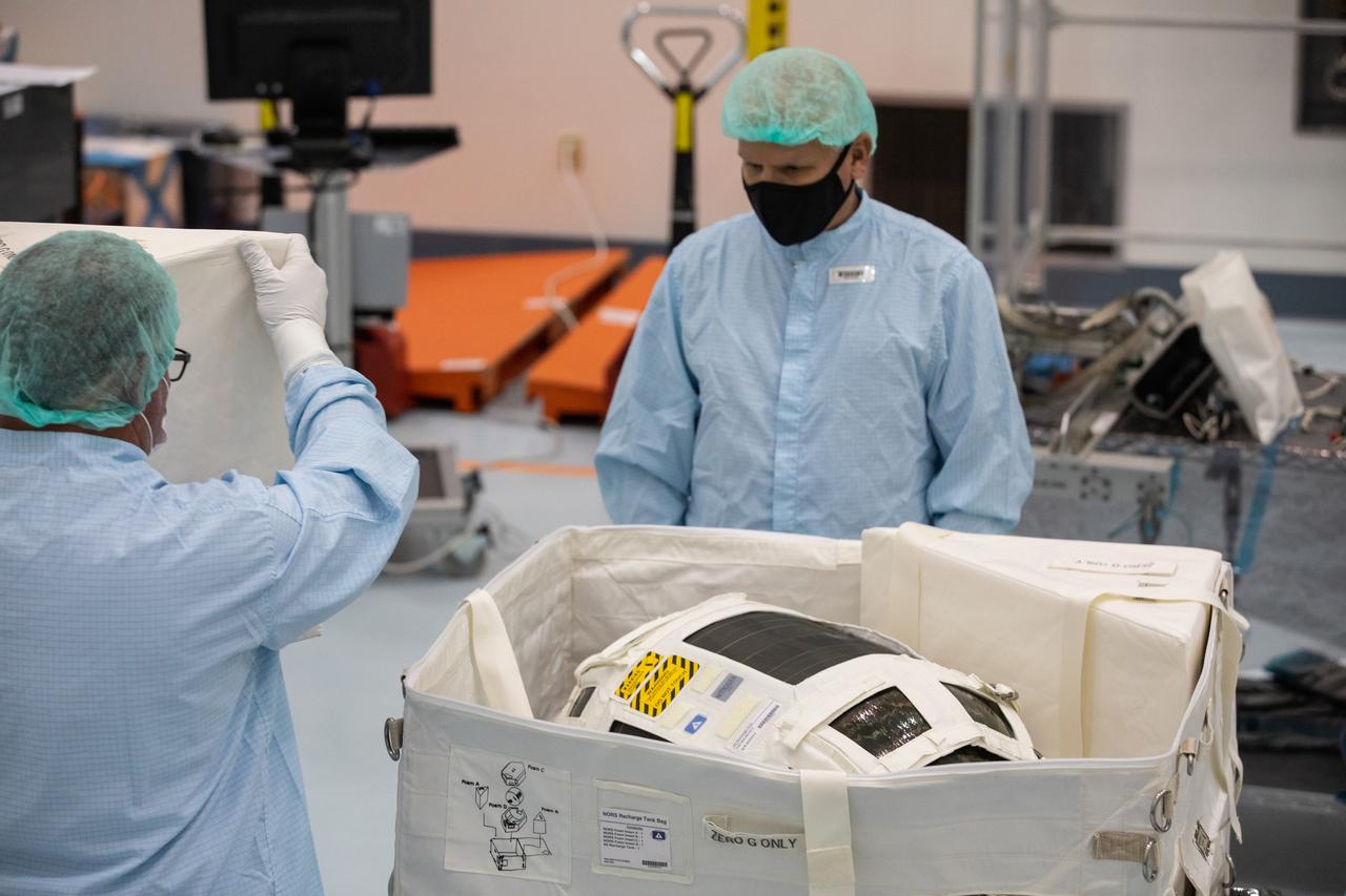
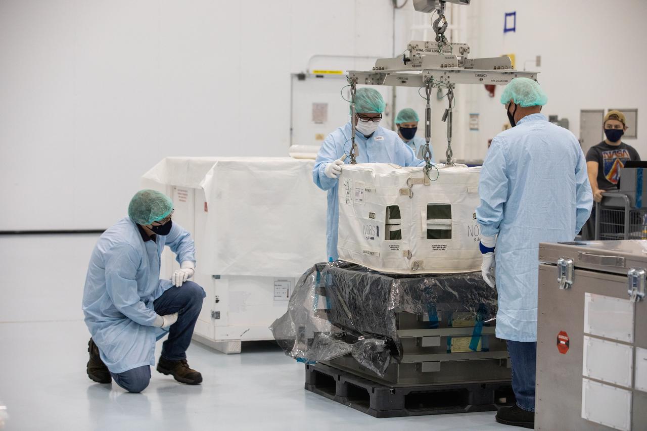
Technicians unpack and inspect a Nitrogen/Oxygen Recharge System (NORS) tank inside the Space Station Processing Facility high bay at NASA’s Kennedy Space Center in Florida on July 16, 2020. The NORS tanks and their support fixtures are designed to connect to the International Space Station’s existing air supply network to refill the previous generation of tanks installed during construction of the space station. These reusable tanks measure 3 feet long and 21 inches in diameter, and weigh about 200 pounds when filled. Once onboard, the tanks will be used to fill the oxygen and nitrogen tanks that supply the needed gases to the space station’s airlock for spacewalks. They could also be used to replenish the atmosphere inside the station. The NORS tanks will launch to the station later in the year on a commercial resupply mission.
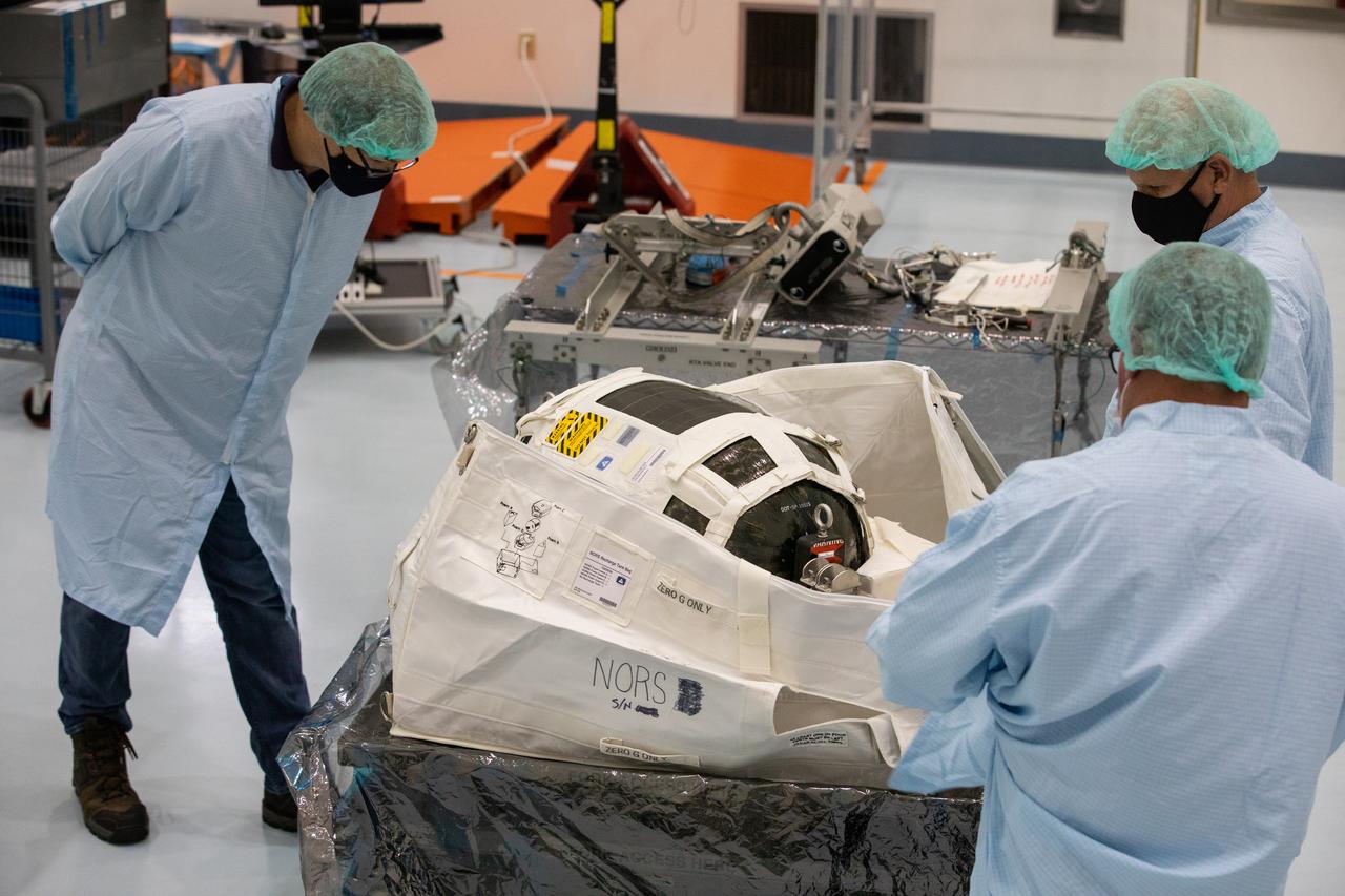
Technicians unpack and inspect a Nitrogen/Oxygen Recharge System (NORS) tank inside the Space Station Processing Facility high bay at NASA’s Kennedy Space Center in Florida on July 16, 2020. The NORS tanks and their support fixtures are designed to connect to the International Space Station’s existing air supply network to refill the previous generation of tanks installed during construction of the space station. These reusable tanks measure 3 feet long and 21 inches in diameter, and weigh about 200 pounds when filled. Once onboard, the tanks will be used to fill the oxygen and nitrogen tanks that supply the needed gases to the space station’s airlock for spacewalks. They could also be used to replenish the atmosphere inside the station. The NORS tanks will launch to the station later in the year on a commercial resupply mission.
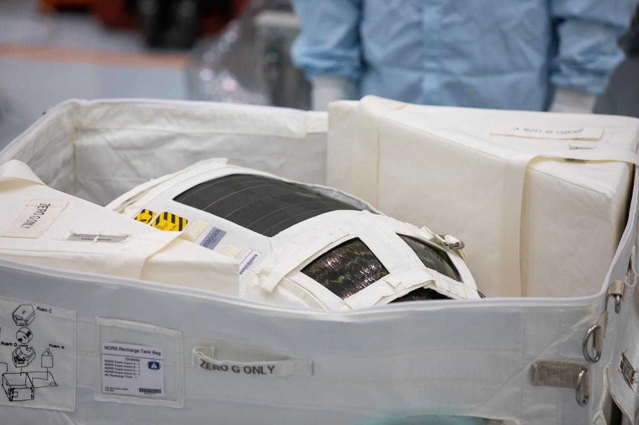
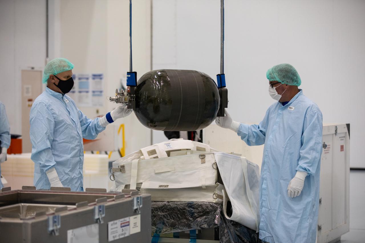
A Nitrogen/Oxygen Recharge System (NORS) tank is unpacked and readied for inspection inside the Space Station Processing Facility high bay at NASA’s Kennedy Space Center in Florida on July 16, 2020. The NORS tanks and their support fixtures are designed to connect to the International Space Station’s existing air supply network to refill the previous generation of tanks installed during construction of the space station. These reusable tanks measure 3 feet long and 21 inches in diameter, and weigh about 200 pounds when filled. Once onboard, the tanks will be used to fill the oxygen and nitrogen tanks that supply the needed gases to the space station’s airlock for spacewalks. They could also be used to replenish the atmosphere inside the station. The NORS tanks will launch to the station later in the year on a commercial resupply mission.
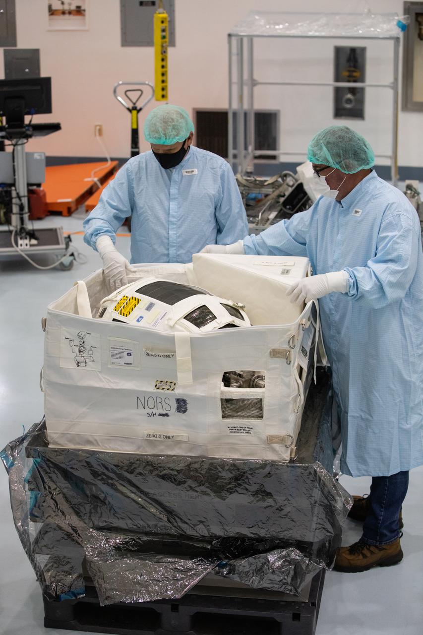
Technicians unpack and inspect a Nitrogen/Oxygen Recharge System (NORS) tank inside the Space Station Processing Facility high bay at NASA’s Kennedy Space Center in Florida on July 16, 2020. The NORS tanks and their support fixtures are designed to connect to the International Space Station’s existing air supply network to refill the previous generation of tanks installed during construction of the space station. These reusable tanks measure 3 feet long and 21 inches in diameter, and weigh about 200 pounds when filled. Once onboard, the tanks will be used to fill the oxygen and nitrogen tanks that supply the needed gases to the space station’s airlock for spacewalks. They could also be used to replenish the atmosphere inside the station. The NORS tanks will launch to the station later in the year on a commercial resupply mission.
Technicians unpack and inspect a Nitrogen/Oxygen Recharge System (NORS) tank inside the Space Station Processing Facility high bay at NASA’s Kennedy Space Center in Florida on July 16, 2020. The NORS tanks and their support fixtures are designed to connect to the International Space Station’s existing air supply network to refill the previous generation of tanks installed during construction of the space station. These reusable tanks measure 3 feet long and 21 inches in diameter, and weigh about 200 pounds when filled. Once onboard, the tanks will be used to fill the oxygen and nitrogen tanks that supply the needed gases to the space station’s airlock for spacewalks. They could also be used to replenish the atmosphere inside the station. The NORS tanks will launch to the station later in the year on a commercial resupply mission.
Technicians unpack and inspect a Nitrogen/Oxygen Recharge System (NORS) tank inside the Space Station Processing Facility high bay at NASA’s Kennedy Space Center in Florida on July 16, 2020. The NORS tanks and their support fixtures are designed to connect to the International Space Station’s existing air supply network to refill the previous generation of tanks installed during construction of the space station. These reusable tanks measure 3 feet long and 21 inches in diameter, and weigh about 200 pounds when filled. Once onboard, the tanks will be used to fill the oxygen and nitrogen tanks that supply the needed gases to the space station’s airlock for spacewalks. They could also be used to replenish the atmosphere inside the station. The NORS tanks will launch to the station later in the year on a commercial resupply mission.
Technicians unpack and inspect a Nitrogen/Oxygen Recharge System (NORS) tank inside the Space Station Processing Facility high bay at NASA’s Kennedy Space Center in Florida on July 16, 2020. The NORS tanks and their support fixtures are designed to connect to the International Space Station’s existing air supply network to refill the previous generation of tanks installed during construction of the space station. These reusable tanks measure 3 feet long and 21 inches in diameter, and weigh about 200 pounds when filled. Once onboard, the tanks will be used to fill the oxygen and nitrogen tanks that supply the needed gases to the space station’s airlock for spacewalks. They could also be used to replenish the atmosphere inside the station. The NORS tanks will launch to the station later in the year on a commercial resupply mission.

A technicians inspects a Nitrogen/Oxygen Recharge System (NORS) tank inside the Space Station Processing Facility high bay at NASA’s Kennedy Space Center in Florida on July 16, 2020. The NORS tanks and their support fixtures are designed to connect to the International Space Station’s existing air supply network to refill the previous generation of tanks installed during construction of the space station. These reusable tanks measure 3 feet long and 21 inches in diameter, and weigh about 200 pounds when filled. Once onboard, the tanks will be used to fill the oxygen and nitrogen tanks that supply the needed gases to the space station’s airlock for spacewalks. They could also be used to replenish the atmosphere inside the station. The NORS tanks will launch to the station later in the year on a commercial resupply mission.
Technicians unpack and inspect a Nitrogen/Oxygen Recharge System (NORS) tank inside the Space Station Processing Facility high bay at NASA’s Kennedy Space Center in Florida on July 16, 2020. The NORS tanks and their support fixtures are designed to connect to the International Space Station’s existing air supply network to refill the previous generation of tanks installed during construction of the space station. These reusable tanks measure 3 feet long and 21 inches in diameter, and weigh about 200 pounds when filled. Once onboard, the tanks will be used to fill the oxygen and nitrogen tanks that supply the needed gases to the space station’s airlock for spacewalks. They could also be used to replenish the atmosphere inside the station. The NORS tanks will launch to the station later in the year on a commercial resupply mission.
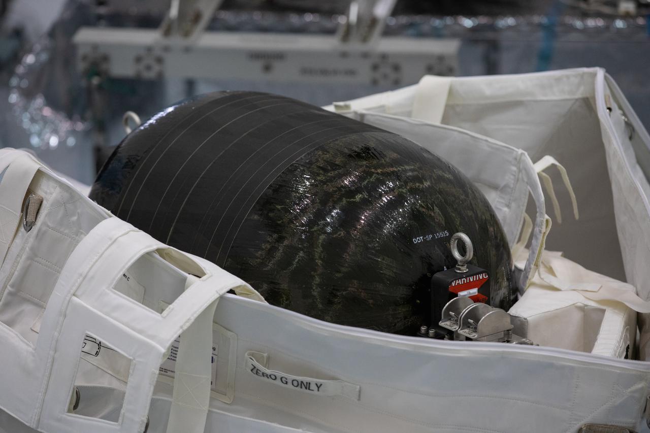
A Nitrogen/Oxygen Recharge System (NORS) tank is unpacked and readied for inspection inside the Space Station Processing Facility high bay at NASA’s Kennedy Space Center in Florida on July 16, 2020. The NORS tanks and their support fixtures are designed to connect to the International Space Station’s existing air supply network to refill the previous generation of tanks installed during construction of the space station. These reusable tanks measure 3 feet long and 21 inches in diameter, and weigh about 200 pounds when filled. Once onboard, the tanks will be used to fill the oxygen and nitrogen tanks that supply the needed gases to the space station’s airlock for spacewalks. They could also be used to replenish the atmosphere inside the station. The NORS tanks will launch to the station later in the year on a commercial resupply mission.
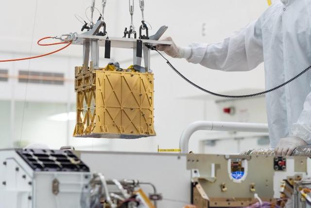
MOXIE (Mars Oxygen In-Situ Resource Utilization Experiment) was launched aboard NASA's Perseverance rover to test a technology for extracting oxygen from the Red Planet's carbon dioxide-rich atmosphere. Audio of MOXIE's air compressor at work on Mars was captured by the microphone on Perseverance's SuperCam instrument on May 27, 2021, the 96th day of the rover's mission. Since Perseverance landed on Mars in 2021, MOXIE generated a total of 122 grams of oxygen – about what a small dog breathes in 10 hours. At its most efficient, MOXIE was able to produce 12 grams of oxygen an hour – twice as much as NASA's original goals for the instrument – at 98% purity or better. On its final, 16th run, on Aug. 7, 2023, the instrument made 9.8 grams of oxygen. MOXIE successfully completed all of its technical requirements and was operated at a variety of conditions throughout a full Mars year, allowing the instrument's developers to learn a great deal about the technology. MOXIE produces molecular oxygen through an electrochemical process that separates one oxygen atom from each molecule of carbon dioxide pumped in from Mars' thin atmosphere. As these gases flow through the system, they're analyzed to check the purity and quantity of oxygen produced. While many of Perseverance's experiments are addressing primary science goals, MOXIE was focused on future human exploration. MOXIE served as the first-ever demonstration of technology that humans could use to survive on, and leave, the Red Planet. An oxygen-producing system could help future missions in various ways, but the most important of them would be as a source of rocket propellant, which would be required in industrial quantities to launch rockets with astronauts for their return trip home. Rather than bringing large quantities of oxygen with them to Mars, future astronauts could live off the land, using materials they find on the planet's surface to survive. This concept – called in-situ resource utilization, or ISRU – has evolved into a growing area of research. A key objective for Perseverance's mission on Mars is astrobiology, including the search for signs of ancient microbial life. The rover will characterize the planet's geology and past climate, pave the way for human exploration of the Red Planet, and be the first mission to collect and cache Martian rock and regolith (broken rock and dust). Subsequent NASA missions, in cooperation with ESA (European Space Agency), would send spacecraft to Mars to collect these sealed samples from the surface and return them to Earth for in-depth analysis. The Mars 2020 Perseverance mission is part of NASA's Moon to Mars exploration approach, which includes Artemis missions to the Moon that will help prepare for human exploration of the Red Planet. Audio file available at https://photojournal.jpl.nasa.gov/catalog/PIA26041

An artist's rendering of the air-breathing, hypersonic X-43B, the third and largest of NASA's Hyper-X series flight demonstrators, which could fly later this decade. Revolutionizing the way we gain access to space is NASA's primary goal for the Hypersonic Investment Area, managed for NASA by the Advanced Space Transportation Program at the Marshall Space Flight Center in Huntsville, Alabama. The Hypersonic Investment area, which includes leading-edge partners in industry and academia, will support future generation reusable vehicles and improved access to space. These technology demonstrators, intended for flight testing by decade's end, are expected to yield a new generation of vehicles that routinely fly about 100,000 feet above Earth's surface and reach sustained speeds in excess of Mach 5 (3,750 mph), the point at which "supersonic" flight becomes "hypersonic" flight. The flight demonstrators, the Hyper-X series, will be powered by air-breathing rocket or turbine-based engines, and ram/scramjets. Air-breathing engines, known as combined-cycle systems, achieve their efficiency gains over rocket systems by getting their oxygen for combustion from the atmosphere, as opposed to a rocket that must carry its oxygen. Once a hypersonic vehicle has accelerated to more than twice the speed of sound, the turbine or rockets are turned off, and the engine relies solely on oxygen in the atmosphere to burn fuel. When the vehicle has accelerated to more than 10 to 15 times the speed of sound, the engine converts to a conventional rocket-powered system to propel the craft into orbit or sustain it to suborbital flight speed. NASA's series of hypersonic flight demonstrators includes three air-breathing vehicles: the X-43A, X-43B and X-43C.
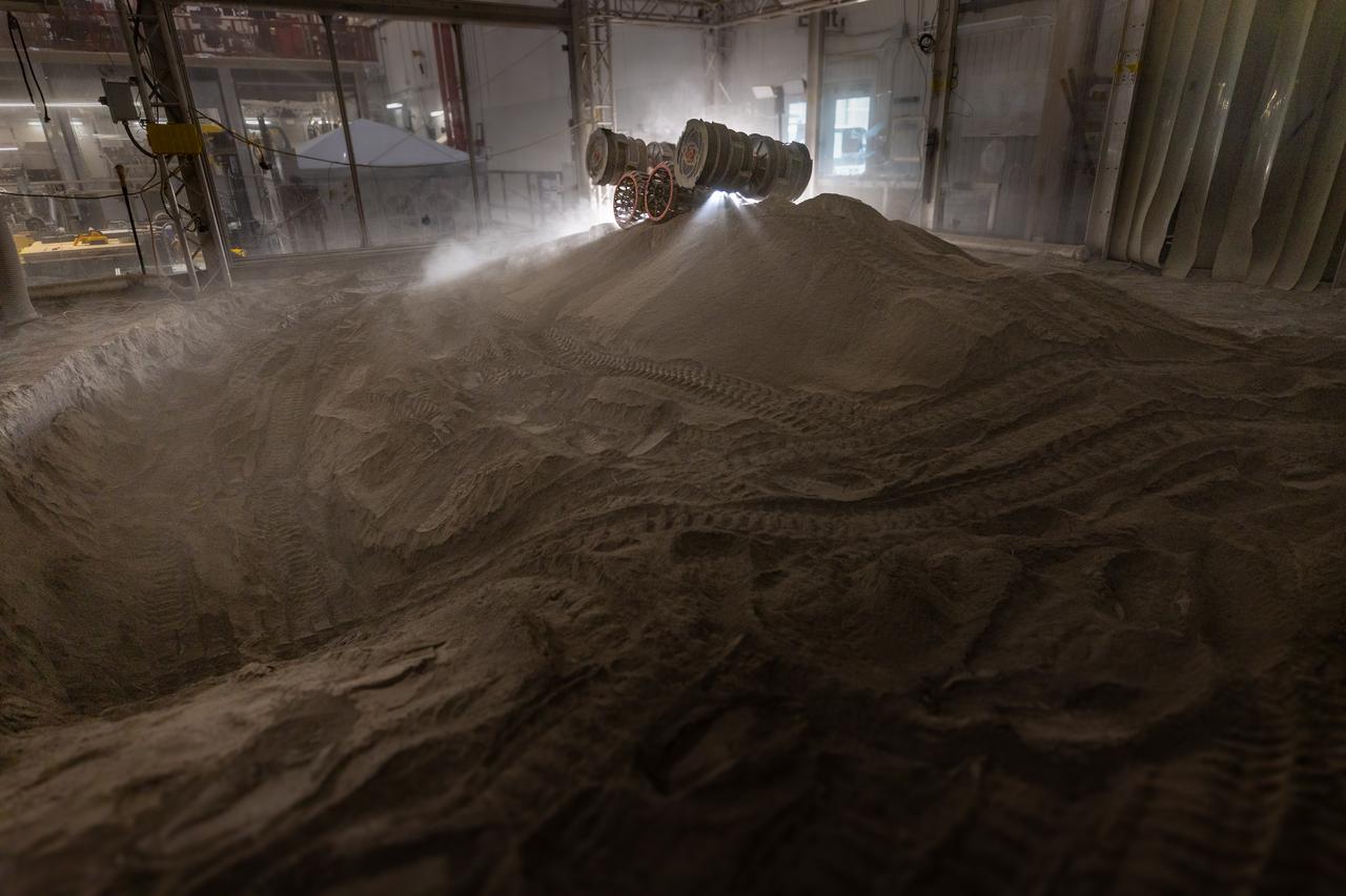
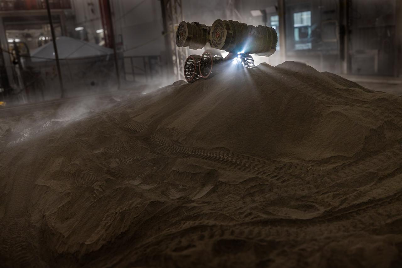
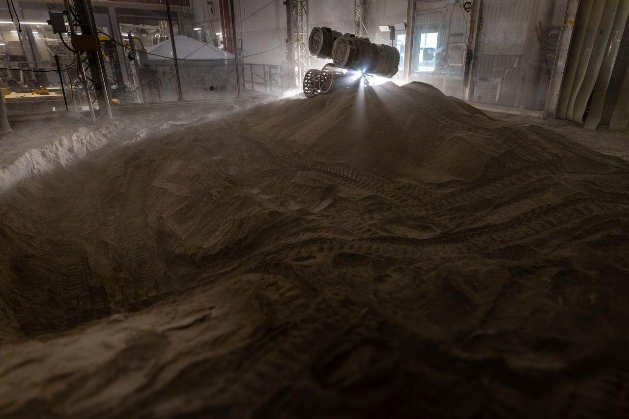
NASA’s RASSOR (Regolith Advanced Surface Systems Operations Robot) manipulates simulated regolith, or lunar dust found on the Moon’s surface, to create a three-foot berm during a site preparation test inside of the Granular Mechanics and Regolith Operations Lab at the agency’s Kennedy Space Center in Florida on Tuesday, June 3, 2025. The opposing motion of the bucket drums helps RASSOR grip the surface in low-gravity environments like the Moon or Mars. With this unique capability, RASSOR can traverse the rough surface to dig, load, haul, and dump regolith that could be used in construction or broken down into hydrogen, oxygen, or water, resources critical for sustaining human presence. RASSOR represents an earlier generation technology that informed the development of NASA’s IPEx (In-Situ Resource Utilization Pilot Excavator), serving as a precursor and foundational platform for the advanced excavation systems and autonomous capabilities now being demonstrated by this Moon-mining robot.
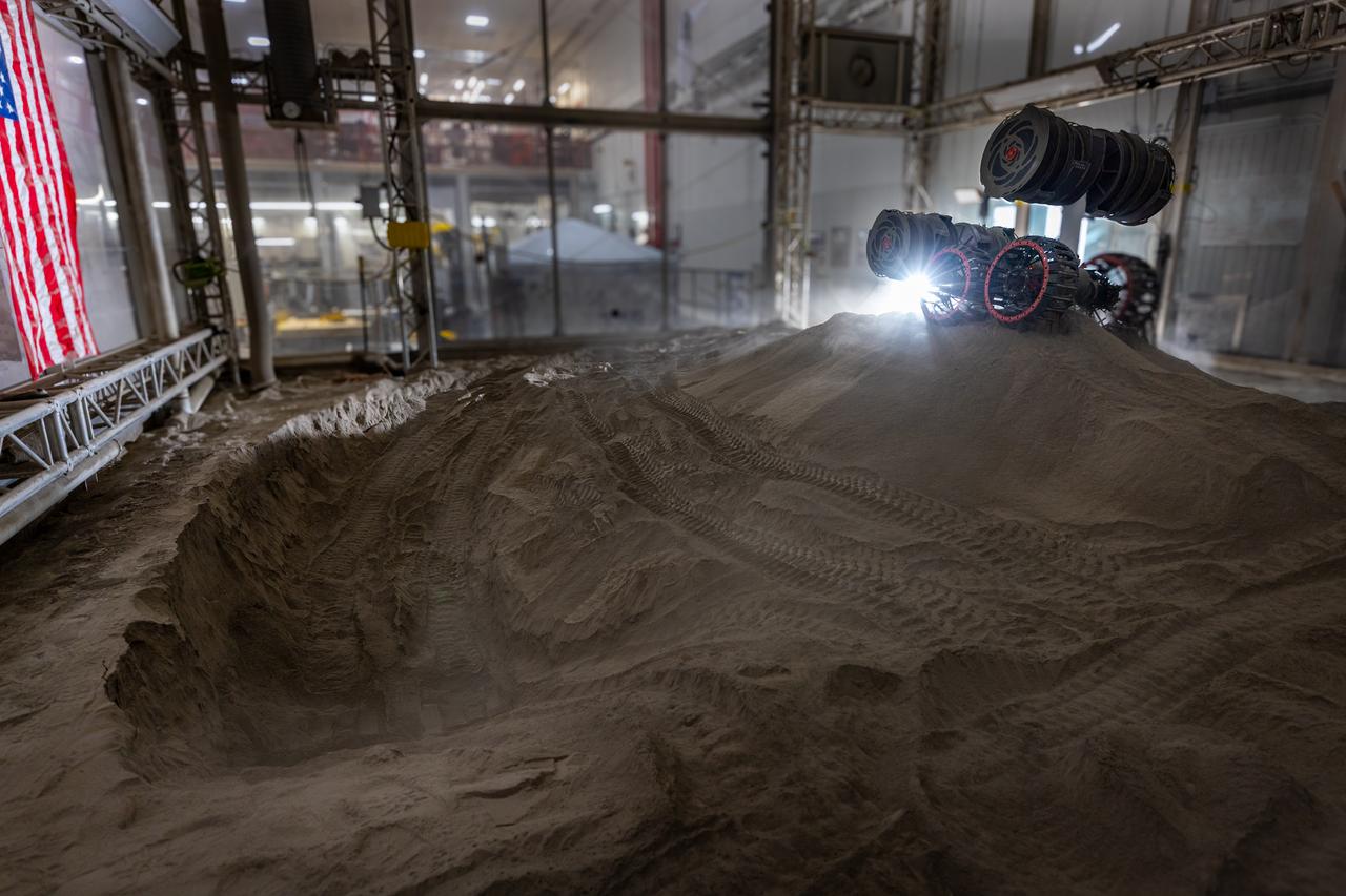
NASA’s RASSOR (Regolith Advanced Surface Systems Operations Robot) manipulates simulated regolith, or lunar dust found on the Moon’s surface, to create a three-foot berm during a site preparation test inside of the Granular Mechanics and Regolith Operations Lab at the agency’s Kennedy Space Center in Florida on Tuesday, June 3, 2025. The opposing motion of the bucket drums helps RASSOR grip the surface in low-gravity environments like the Moon or Mars. With this unique capability, RASSOR can traverse the rough surface to dig, load, haul, and dump regolith that could be used in construction or broken down into hydrogen, oxygen, or water, resources critical for sustaining human presence. RASSOR represents an earlier generation technology that informed the development of NASA’s IPEx (In-Situ Resource Utilization Pilot Excavator), serving as a precursor and foundational platform for the advanced excavation systems and autonomous capabilities now being demonstrated by this Moon-mining robot.
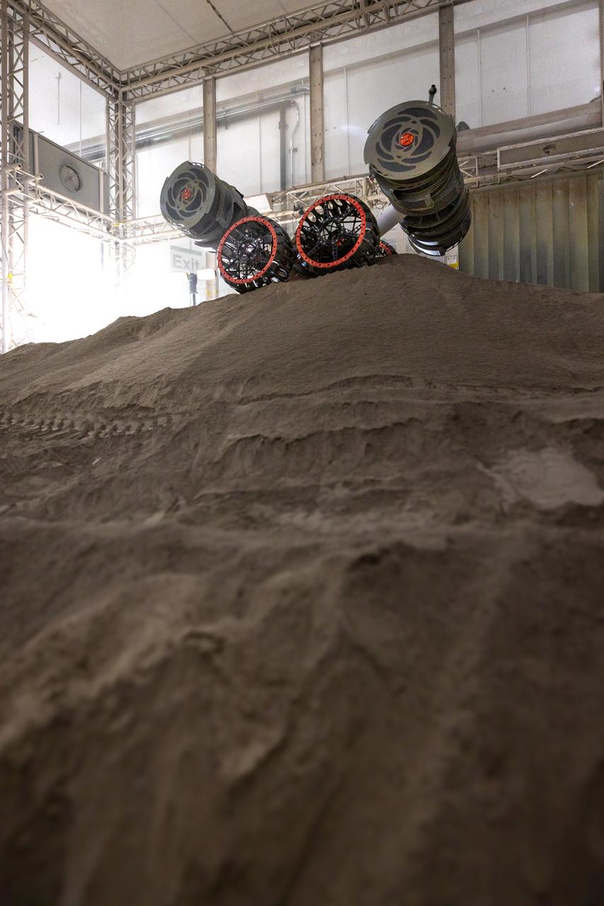
NASA’s RASSOR (Regolith Advanced Surface Systems Operations Robot) manipulates simulated regolith, or lunar dust found on the Moon’s surface, to create a three-foot berm during a site preparation test inside of the Granular Mechanics and Regolith Operations Lab at the agency’s Kennedy Space Center in Florida on Tuesday, June 3, 2025. The opposing motion of the bucket drums helps RASSOR grip the surface in low-gravity environments like the Moon or Mars. With this unique capability, RASSOR can traverse the rough surface to dig, load, haul, and dump regolith that could be used in construction or broken down into hydrogen, oxygen, or water, resources critical for sustaining human presence. RASSOR represents an earlier generation technology that informed the development of NASA’s IPEx (In-Situ Resource Utilization Pilot Excavator), serving as a precursor and foundational platform for the advanced excavation systems and autonomous capabilities now being demonstrated by this Moon-mining robot.
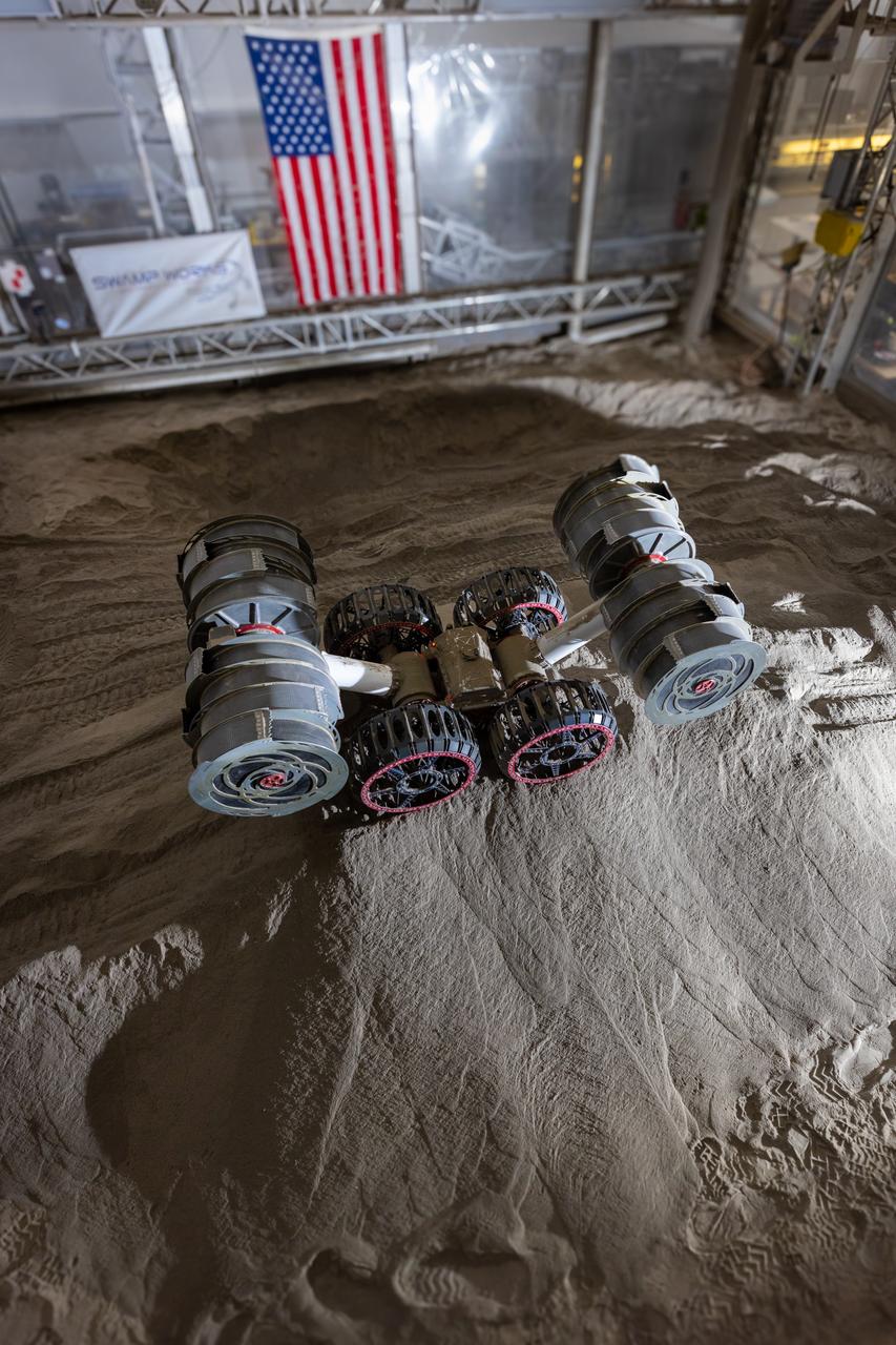
NASA’s RASSOR (Regolith Advanced Surface Systems Operations Robot) manipulates simulated regolith, or lunar dust found on the Moon’s surface, to create a three-foot berm during a site preparation test inside of the Granular Mechanics and Regolith Operations Lab at the agency’s Kennedy Space Center in Florida on Tuesday, June 3, 2025. The opposing motion of the bucket drums helps RASSOR grip the surface in low-gravity environments like the Moon or Mars. With this unique capability, RASSOR can traverse the rough surface to dig, load, haul, and dump regolith that could be used in construction or broken down into hydrogen, oxygen, or water, resources critical for sustaining human presence. RASSOR represents an earlier generation technology that informed the development of NASA’s IPEx (In-Situ Resource Utilization Pilot Excavator), serving as a precursor and foundational platform for the advanced excavation systems and autonomous capabilities now being demonstrated by this Moon-mining robot.
NASA’s RASSOR (Regolith Advanced Surface Systems Operations Robot) manipulates simulated regolith, or lunar dust found on the Moon’s surface, to create a three-foot berm during a site preparation test inside of the Granular Mechanics and Regolith Operations Lab at the agency’s Kennedy Space Center in Florida on Tuesday, June 3, 2025. The opposing motion of the bucket drums helps RASSOR grip the surface in low-gravity environments like the Moon or Mars. With this unique capability, RASSOR can traverse the rough surface to dig, load, haul, and dump regolith that could be used in construction or broken down into hydrogen, oxygen, or water, resources critical for sustaining human presence. RASSOR represents an earlier generation technology that informed the development of NASA’s IPEx (In-Situ Resource Utilization Pilot Excavator), serving as a precursor and foundational platform for the advanced excavation systems and autonomous capabilities now being demonstrated by this Moon-mining robot.
NASA’s RASSOR (Regolith Advanced Surface Systems Operations Robot) manipulates simulated regolith, or lunar dust found on the Moon’s surface, to create a three-foot berm during a site preparation test inside of the Granular Mechanics and Regolith Operations Lab at the agency’s Kennedy Space Center in Florida on Tuesday, June 3, 2025. The opposing motion of the bucket drums helps RASSOR grip the surface in low-gravity environments like the Moon or Mars. With this unique capability, RASSOR can traverse the rough surface to dig, load, haul, and dump regolith that could be used in construction or broken down into hydrogen, oxygen, or water, resources critical for sustaining human presence. RASSOR represents an earlier generation technology that informed the development of NASA’s IPEx (In-Situ Resource Utilization Pilot Excavator), serving as a precursor and foundational platform for the advanced excavation systems and autonomous capabilities now being demonstrated by this Moon-mining robot.
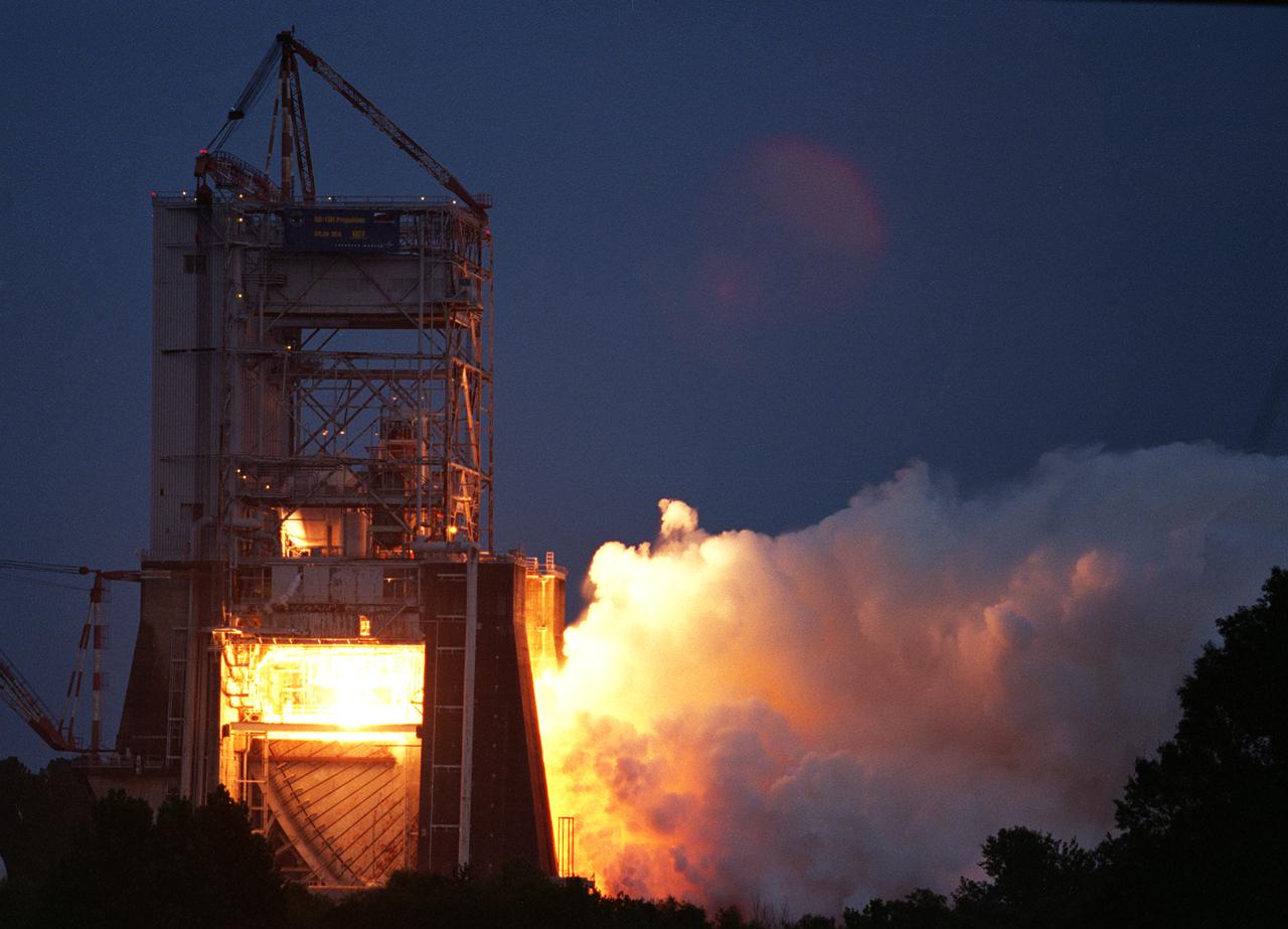
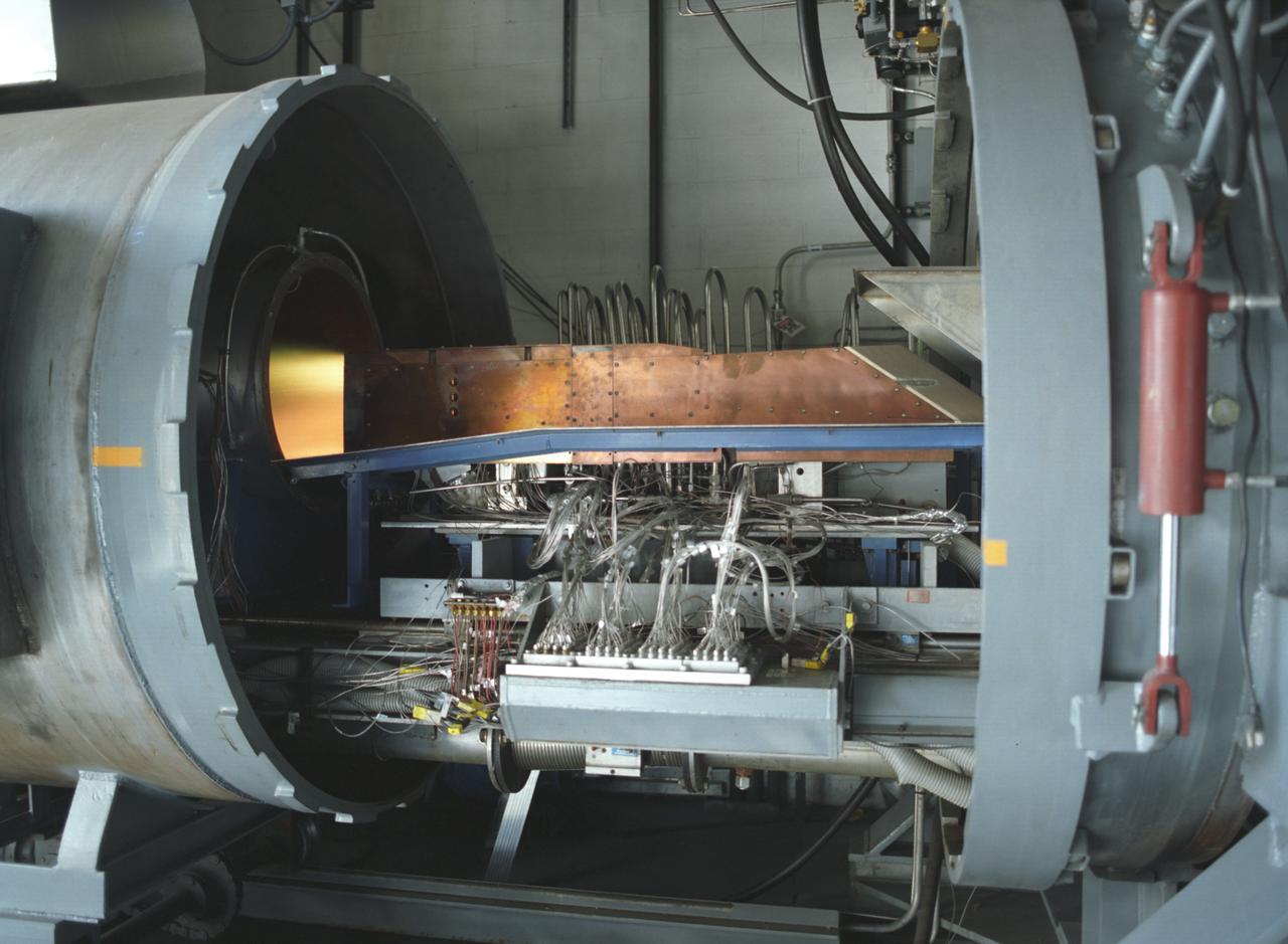
NASA engineers successfully tested a Russian-built rocket engine on November 4, 1998 at the Marshall Space Flight Center (MSFC) Advanced Engine Test Facility, which had been used for testing the Saturn V F-1 engines and Space Shuttle Main engines. The MSFC was under a Space Act Agreement with Lockheed Martin Astronautics of Denver to provide a series of test firings of the Atlas III propulsion system configured with the Russian-designed RD-180 engine. The tests were designed to measure the performance of the Atlas III propulsion system, which included avionics and propellant tanks and lines, and how these components interacted with the RD-180 engine. The RD-180 is powered by kerosene and liquid oxygen, the same fuel mix used in Saturn rockets. The RD-180, the most powerful rocket engine tested at the MSFC since Saturn rocket tests in the 1960s, generated 860,000 pounds of thrust.

This photograph depicts an air-breathing rocket engine prototype in the test bay at the General Applied Science Lab facility in Ronkonkoma, New York. Air-breathing engines, known as rocket based, combined-cycle engines, get their initial take-off power from specially designed rockets, called air-augmented rockets, that boost performance about 15 percent over conventional rockets. When the vehicle's velocity reaches twice the speed of sound, the rockets are turned off and the engine relies totally on oxygen in the atmosphere to burn hydrogen fuel, as opposed to a rocket that must carry its own oxygen, thus reducing weight and flight costs. Once the vehicle has accelerated to about 10 times the speed of sound, the engine converts to a conventional rocket-powered system to propel the craft into orbit or sustain it to suborbital flight speed. NASA's Advanced Space Transportation Program at Marshall Space Flight Center, along with several industry partners and collegiate forces, is developing this technology to make space transportation affordable for everyone from business travelers to tourists. The goal is to reduce launch costs from today's price tag of $10,000 per pound to only hundreds of dollars per pound. NASA's series of hypersonic flight demonstrators currently include three air-breathing vehicles: the X-43A, X-43B and X-43C.
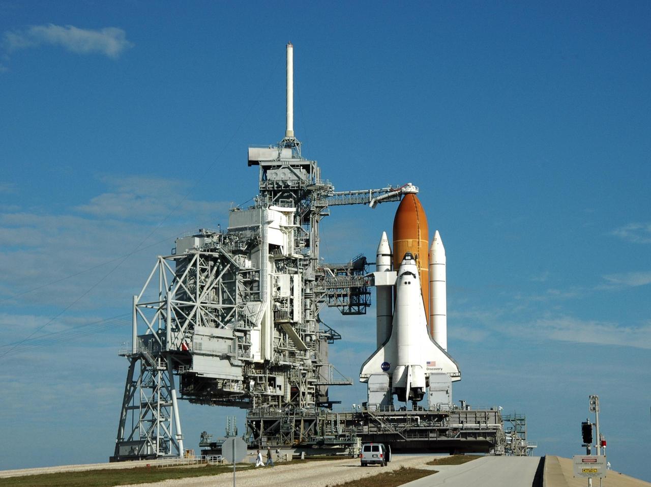
KENNEDY SPACE CENTER, FLA. -- Under a blue sky streaked with clouds, Launch Pad 39B holds Space Shuttle Discovery, ready for launch of mission STS-116. At the far left is the rotating service structure, rolled back after midnight in preparation for launch. Next to Discovery is the fixed service structure, with the 80-foot-high lightning mast on top, part of the lightning protection system on the pad. Beneath Discovery's wings are the tail masts, which provide several umbilical connections to the orbiter, including a liquid-oxygen line through one and a liquid-hydrogen line through another. Seen above the golden external tank is the vent hood (known as the "beanie cap") at the end of the gaseous oxygen vent arm, extending from the FSS. Vapors are created as the liquid oxygen in the external tank boil off. The hood vents the gaseous oxygen vapors away from the space shuttle vehicle. Below it, also extending toward Discovery from the FSS, is the orbiter access arm with the White Room at the end. The crew gains access into the orbiter through the White Room. Discovery is scheduled to launch on mission STS-116 at 9:35 p.m. today. On the mission, the crew will deliver truss segment, P5, to the International Space Station and begin the intricate process of reconfiguring and redistributing the power generated by two pairs of U.S. solar arrays. The P5 will be mated to the P4 truss that was delivered and attached during the STS-115 mission in September. Photo credit: NASA/Ken Thornsley

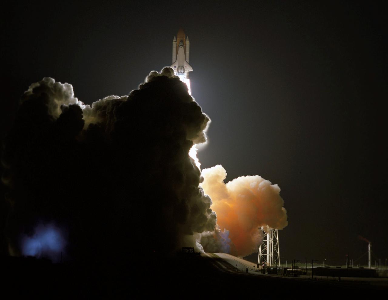
Against a black night sky, the Space Shuttle Discovery and its seven-member crew head toward Earth-orbit and a scheduled linkup with the International Space Station (ISS). Liftoff from the Kennedy Space Center's launch pad 39B occurred at 8:47 p.m. (EST) on Dec. 9, 2006 in what was the first evening shuttle launch since 2002. The primary mission objective was to deliver and install the P5 truss element. The P5 installation was conducted during the first of three space walks, and involved use of both the shuttle and station’s robotic arms. The remainder of the mission included a major reconfiguration and activation of the ISS electrical and thermal control systems, as well as delivery of Zvezda Service Module debris panels, which will increase ISS protection from potential impacts of micro-meteorites and orbital debris. Two major payloads developed at the Marshall Space Flight Center (MSFC) were also delivered to the Station. The Lab-On-A Chip Application Development Portable Test System (LOCAD-PTS) and the Water Delivery System, a vital component of the Station’s Oxygen Generation System.
Against a black night sky, the Space Shuttle Discovery and its seven-member crew head toward Earth-orbit and a scheduled linkup with the International Space Station (ISS). Liftoff from the Kennedy Space Center's launch pad 39B occurred at 8:47 p.m. (EST) on Dec. 9, 2006 in what was the first evening shuttle launch since 2002. The primary mission objective was to deliver and install the P5 truss element. The P5 installation was conducted during the first of three space walks, and involved use of both the shuttle and station’s robotic arms. The remainder of the mission included a major reconfiguration and activation of the ISS electrical and thermal control systems, as well as delivery of Zvezda Service Module debris panels, which will increase ISS protection from potential impacts of micro-meteorites and orbital debris. Two major payloads developed at the Marshall Space Flight Center (MSFC) were also delivered to the Station. The Lab-On-A Chip Application Development Portable Test System (LOCAD-PTS) and the Water Delivery System, a vital component of the Station’s Oxygen Generation System.
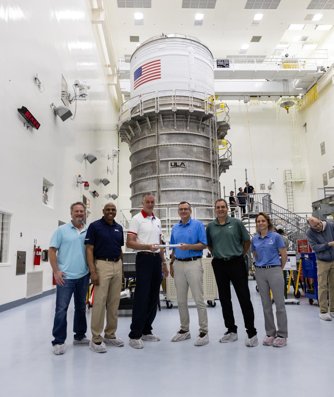
Managers from NASA and industry partners for NASA’s SLS (Space Launch System) rocket upper stage hand off the baton to managers from the agency’s Exploration Ground Systems (EGS) are shown with the SLS interim cryogenic propulsion stage inside the Multi-Payload Processing Facility at NASA’s Kennedy Space Center in Florida on Monday, March 10, 2025, after being transported from United Launch Alliance’s (ULA) Delta Operations Center at nearby Cape Canaveral Space Force Station. From left to right are Jim Bonato, ICPS Mission Manager, ULA; Ron Fortson, Director and General Manager, ULA; Chris Calfee, Spacecraft/Payload Integration and Evolution element manager, SLS; Cliff Lanham, senior vehicle operations manager, EGS; Todd Lamond, Strategic Planning and Integration, Amentum; and Natasha Wiest, Interim Director, Boeing Core Stage Integrated Product Team; The interim cryogenic propulsion stage is a liquid oxygen and liquid hydrogen-based system that will fire its RL10 engine to give the Orion spacecraft the big in-space push needed to fly around the Moon and back.

The Space Shuttle represented an entirely new generation of space vehicles, the world's first reusable spacecraft. Unlike earlier expendable rockets, the Shuttle was designed to be launched over and over again and would serve as a system for ferrying payloads and persornel to and from Earth orbit. The Shuttle's major components are the orbiter spacecraft; the three main engines, with a combined thrust of more than 1.2 million pounds; the huge external tank (ET) that feeds the liquid hydrogen fuel and liquid oxygen oxidizer to the three main engines; and the two solid rocket boosters (SRB's), with their combined thrust of some 5.8 million pounds, that provide most of the power for the first two minutes of flight. Crucially involved with the Space Shuttle program virtually from its inception, the Marshall Space Flight Center (MSFC) played a leading role in the design, development, testing, and fabrication of many major Shuttle propulsion components. The MSFC was assigned responsibility for developing the Shuttle orbiter's high-performance main engines, the most complex rocket engines ever built. The MSFC was also responsible for developing the Shuttle's massive ET and the solid rocket motors and boosters.

The Space Shuttle represented an entirely new generation of space vehicle, the world's first reusable spacecraft. Unlike earlier expendable rockets, the Shuttle was designed to be launched over and over again and would serve as a system for ferrying payloads and persornel to and from Earth orbit. The Shuttle's major components are the orbiter spacecraft; the three main engines, with a combined thrust of more than 1.2 million pounds; the huge external tank (ET) that feeds the liquid hydrogen fuel and liquid oxygen oxidizer to the three main engines; and the two solid rocket boosters (SRB's), with their combined thrust of some 5.8 million pounds. The SRB's provide most of the power for the first two minutes of flight. Crucially involved with the Space Shuttle program virtually from its inception, the Marshall Space Flight Center (MSFC) played a leading role in the design, development, testing, and fabrication of many major Shuttle propulsion components. The MSFC was assigned responsibility for developing the Shuttle orbiter's high-performance main engines, the most complex rocket engines ever built. The MSFC was also responsible for developing the Shuttle's massive ET and the solid rocket motors and boosters.
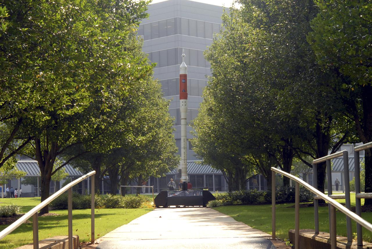
A model of the new Aries I crew launch vehicle, for which NASA is designing, testing and evaluating hardware and related systems, is seen here on display at the Marshall Space Fight Center (MSFC), in Huntsville, Alabama. The Ares I crew launch vehicle is the rocket that will carry a new generation of space explorers into orbit. Under the goals of the Vision for Space Exploration, Ares I is a chief component of the cost-effective space transportation infrastructure being developed by NASA’s Constellation Program. These transportation systems will safely and reliably carry human explorers back to the moon, and then onward to Mars and other destinations in the solar system. The Ares I effort includes multiple project element teams at NASA centers and contract organizations around the nation, and is led by the Exploration Launch Projects Office at NASA’s MFSC. Together, these teams are developing vehicle hardware, evolving proven technologies, and testing components and systems. Their work builds on powerful, reliable space shuttle propulsion elements and nearly a half-century of NASA space flight experience and technological advances. Ares I is an inline, two-stage rocket configuration topped by the Crew Exploration Vehicle, its service module and a launch abort system. The launch vehicle’s first stage is a single, five-segment reusable solid rocket booster derived from the Space Shuttle Program’s reusable solid rocket motor that burns a specially formulated and shaped solid propellant called polybutadiene acrylonitrile (PBAN). The second or upper stage will be propelled by a J-2X main engine fueled with liquid oxygen and liquid hydrogen. In addition to its primary mission of carrying crews of four to six astronauts to Earth orbit, the launch vehicle’s 25-ton payload capacity might be used for delivering cargo to space, bringing resources and supplies to the International Space Station or dropping payloads off in orbit for retrieval and transport to exploration teams on the moon. Crew transportation to the space station is planned to begin no later than 2014. The first lunar excursion is scheduled for the 2020 timeframe.
This photograph depicts an air-breathing rocket engine that completed an hour or 3,600 seconds of testing at the General Applied Sciences Laboratory in Ronkonkoma, New York. Referred to as ARGO by its design team, the engine is named after the mythological Greek ship that bore Jason and the Argonauts on their epic voyage of discovery. Air-breathing engines, known as rocket based, combined-cycle engines, get their initial take-off power from specially designed rockets, called air-augmented rockets, that boost performance about 15 percent over conventional rockets. When the vehicle's velocity reaches twice the speed of sound, the rockets are turned off and the engine relies totally on oxygen in the atmosphere to burn hydrogen fuel, as opposed to a rocket that must carry its own oxygen, thus reducing weight and flight costs. Once the vehicle has accelerated to about 10 times the speed of sound, the engine converts to a conventional rocket-powered system to propel the craft into orbit or sustain it to suborbital flight speed. NASA's Advanced SpaceTransportation Program at Marshall Space Flight Center, along with several industry partners and collegiate forces, is developing this technology to make space transportation affordable for everyone from business travelers to tourists. The goal is to reduce launch costs from today's price tag of $10,000 per pound to only hundreds of dollars per pound. NASA's series of hypersonic flight demonstrators currently include three air-breathing vehicles: the X-43A, X-43B and X-43C.
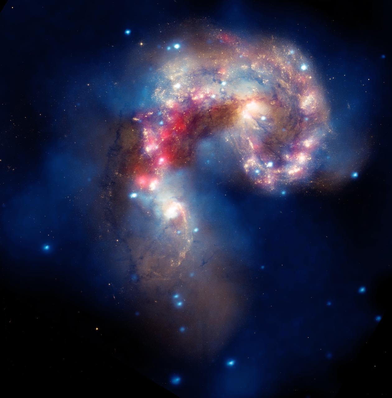
NASA image release August 5, 2010 A beautiful new image of two colliding galaxies has been released by NASA's Great Observatories. The Antennae galaxies, located about 62 million light-years from Earth, are shown in this composite image from the Chandra X-ray Observatory (blue), the Hubble Space Telescope (gold and brown), and the Spitzer Space Telescope (red). The Antennae galaxies take their name from the long antenna-like "arms," seen in wide-angle views of the system. These features were produced by tidal forces generated in the collision. The collision, which began more than 100 million years ago and is still occurring, has triggered the formation of millions of stars in clouds of dusts and gas in the galaxies. The most massive of these young stars have already sped through their evolution in a few million years and exploded as supernovas. The X-ray image from Chandra shows huge clouds of hot, interstellar gas that have been injected with rich deposits of elements from supernova explosions. This enriched gas, which includes elements such as oxygen, iron, magnesium, and silicon, will be incorporated into new generations of stars and planets. The bright, point-like sources in the image are produced by material falling onto black holes and neutron stars that are remnants of the massive stars. Some of these black holes may have masses that are almost one hundred times that of the Sun. The Spitzer data show infrared light from warm dust clouds that have been heated by newborn stars, with the brightest clouds lying in the overlapping region between the two galaxies. The Hubble data reveal old stars and star-forming regions in gold and white, while filaments of dust appear in brown. Many of the fainter objects in the optical image are clusters containing thousands of stars. The Chandra image was taken in December 1999. The Spitzer image was taken in December 2003. The Hubble image was taken in July 2004, and February 2005. Credit: NASA, ESA, SAO, CXC, JPL-Caltech, and STScI Acknowledgment: G. Fabbiano and Z. Wang (Harvard-Smithsonian CfA), and B. Whitmore (STScI)

NASA image release August 5, 2010 A beautiful new image of two colliding galaxies has been released by NASA's Great Observatories. The Antennae galaxies, located about 62 million light-years from Earth, are shown in this composite image from the Chandra X-ray Observatory (blue), the Hubble Space Telescope (gold and brown), and the Spitzer Space Telescope (red). The Antennae galaxies take their name from the long antenna-like "arms," seen in wide-angle views of the system. These features were produced by tidal forces generated in the collision. The collision, which began more than 100 million years ago and is still occurring, has triggered the formation of millions of stars in clouds of dusts and gas in the galaxies. The most massive of these young stars have already sped through their evolution in a few million years and exploded as supernovas. The X-ray image from Chandra shows huge clouds of hot, interstellar gas that have been injected with rich deposits of elements from supernova explosions. This enriched gas, which includes elements such as oxygen, iron, magnesium, and silicon, will be incorporated into new generations of stars and planets. The bright, point-like sources in the image are produced by material falling onto black holes and neutron stars that are remnants of the massive stars. Some of these black holes may have masses that are almost one hundred times that of the Sun. The Spitzer data show infrared light from warm dust clouds that have been heated by newborn stars, with the brightest clouds lying in the overlapping region between the two galaxies. The Hubble data reveal old stars and star-forming regions in gold and white, while filaments of dust appear in brown. Many of the fainter objects in the optical image are clusters containing thousands of stars. The Chandra image was taken in December 1999. The Spitzer image was taken in December 2003. The Hubble image was taken in July 2004, and February 2005. To read more go to: <a href="http://www.nasa.gov/mission_pages/chandra/multimedia/antennae.html" rel="nofollow">www.nasa.gov/mission_pages/chandra/multimedia/antennae.html</a> <b><a href="http://www.nasa.gov/centers/goddard/home/index.html" rel="nofollow">NASA Goddard Space Flight Center</a></b> is home to the nation's largest organization of combined scientists, engineers and technologists that build spacecraft, instruments and new technology to study the Earth, the sun, our solar system, and the universe. <b>Follow us on <a href="http://twitter.com/NASA_GoddardPix" rel="nofollow">Twitter</a></b> <b>Join us on <a href="http://www.facebook.com/pages/Greenbelt-MD/NASA-Goddard/395013845897?ref=tsd" rel="nofollow">Facebook</a><b></b></b> Credit: NASA, ESA, SAO, CXC, JPL-Caltech, and STScI Acknowledgment: G. Fabbiano and Z. Wang (Harvard-Smithsonian CfA), and B. Whitmore (STScI)
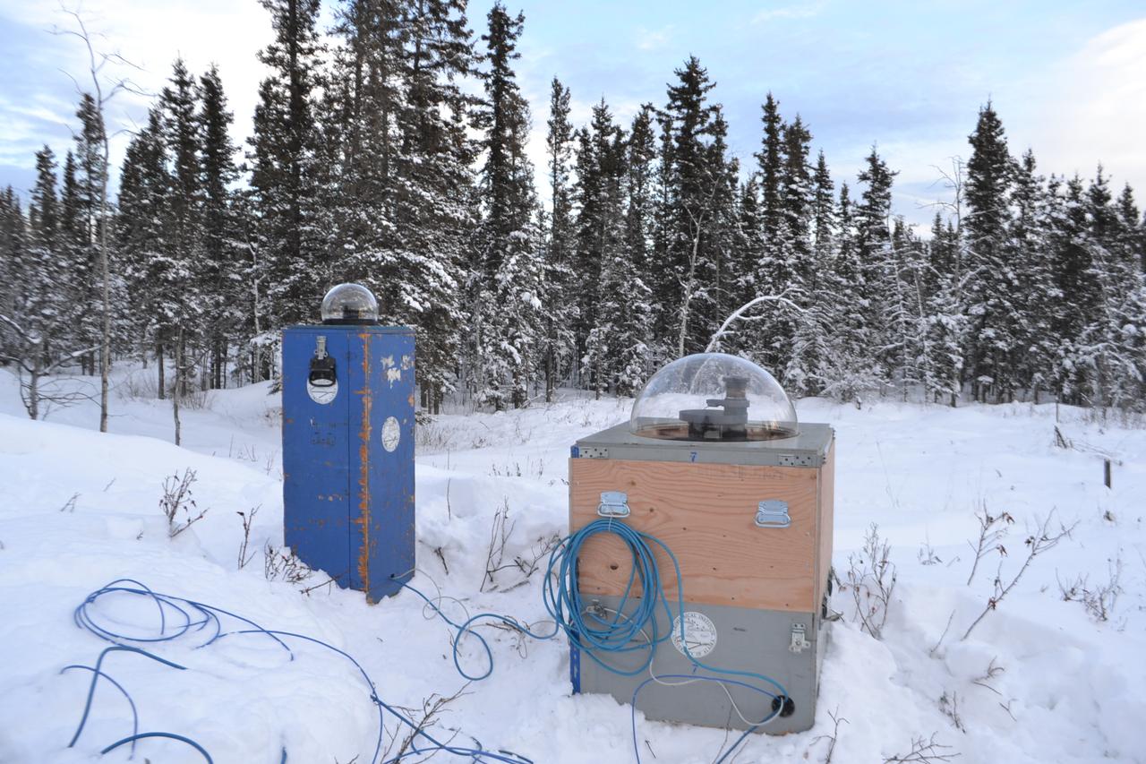
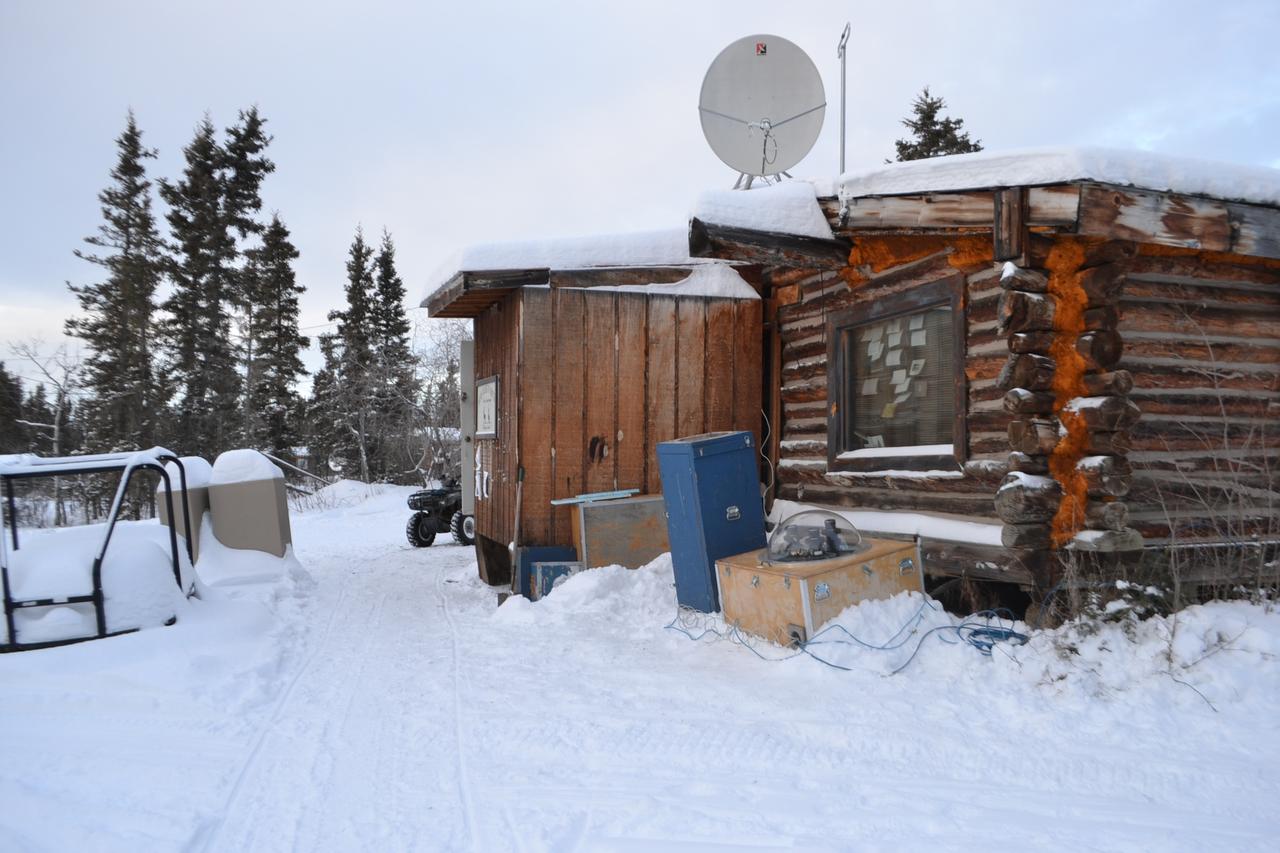
The NASA-funded Ground-to-Rocket Electron-Electrodynamics Correlative Experiment, or GREECE, wants to understand aurora. Specifically, it will study classic auroral curls that swirl through the sky like cream in a cup of coffee. The GREECE instruments travel on a sounding rocket that launches for a ten-minute ride right through the heart of the aurora reaching its zenith over the native village of Venetie, Alaska. To study the curl structures, GREECE consists of two parts: ground-based imagers located in Venetie to track the aurora from the ground and the rocket to take measurements from the middle of the aurora itself. At their simplest, auroras are caused when particles from the sun funnel over to Earth's night side, generate electric currents, and trigger a shower of particles that strike oxygen and nitrogen some 60 to 200 miles up in Earth's atmosphere, releasing a flash of light. But the details are always more complicated, of course. Researchers wish to understand the aurora, and movement of plasma in general, at much smaller scales including such things as how different structures are formed there. This is a piece of information, which in turn, helps paint a picture of the sun-Earth connection and how energy and particles from the sun interact with Earth's own magnetic system, the magnetosphere. GREECE is a collaborative effort between SWRI, which developed particle instruments and the ground-based imaging, and the University of California, Berkeley, measuring the electric and magnetic fields. The launch is supported by a sounding rocket team from NASA’s Wallops Flight Facility, Wallops Island, Va. The Poker Flat Research Range is operated by the University of Alaska, Fairbanks. Credit: NASA Goddard <b><a href="http://www.nasa.gov/audience/formedia/features/MP_Photo_Guidelines.html" rel="nofollow">NASA image use policy.</a></b> <b><a href="http://www.nasa.gov/centers/goddard/home/index.html" rel="nofollow">NASA Goddard Space Flight Center</a></b> enables NASA’s mission through four scientific endeavors: Earth Science, Heliophysics, Solar System Exploration, and Astrophysics. Goddard plays a leading role in NASA’s accomplishments by contributing compelling scientific knowledge to advance the Agency’s mission. <b>Follow us on <a href="http://twitter.com/NASAGoddardPix" rel="nofollow">Twitter</a></b> <b>Like us on <a href="http://www.facebook.com/pages/Greenbelt-MD/NASA-Goddard/395013845897?ref=tsd" rel="nofollow">Facebook</a></b> <b>Find us on <a href="http://instagram.com/nasagoddard?vm=grid" rel="nofollow">Instagram</a></b>
The NASA-funded Ground-to-Rocket Electron-Electrodynamics Correlative Experiment, or GREECE, wants to understand aurora. Specifically, it will study classic auroral curls that swirl through the sky like cream in a cup of coffee. The GREECE instruments travel on a sounding rocket that launches for a ten-minute ride right through the heart of the aurora reaching its zenith over the native village of Venetie, Alaska. To study the curl structures, GREECE consists of two parts: ground-based imagers located in Venetie to track the aurora from the ground and the rocket to take measurements from the middle of the aurora itself. At their simplest, auroras are caused when particles from the sun funnel over to Earth's night side, generate electric currents, and trigger a shower of particles that strike oxygen and nitrogen some 60 to 200 miles up in Earth's atmosphere, releasing a flash of light. But the details are always more complicated, of course. Researchers wish to understand the aurora, and movement of plasma in general, at much smaller scales including such things as how different structures are formed there. This is a piece of information, which in turn, helps paint a picture of the sun-Earth connection and how energy and particles from the sun interact with Earth's own magnetic system, the magnetosphere. GREECE is a collaborative effort between SWRI, which developed particle instruments and the ground-based imaging, and the University of California, Berkeley, measuring the electric and magnetic fields. The launch is supported by a sounding rocket team from NASA’s Wallops Flight Facility, Wallops Island, Va. The Poker Flat Research Range is operated by the University of Alaska, Fairbanks. Credit: NASA Goddard <b><a href="http://www.nasa.gov/audience/formedia/features/MP_Photo_Guidelines.html" rel="nofollow">NASA image use policy.</a></b> <b><a href="http://www.nasa.gov/centers/goddard/home/index.html" rel="nofollow">NASA Goddard Space Flight Center</a></b> enables NASA’s mission through four scientific endeavors: Earth Science, Heliophysics, Solar System Exploration, and Astrophysics. Goddard plays a leading role in NASA’s accomplishments by contributing compelling scientific knowledge to advance the Agency’s mission. <b>Follow us on <a href="http://twitter.com/NASAGoddardPix" rel="nofollow">Twitter</a></b> <b>Like us on <a href="http://www.facebook.com/pages/Greenbelt-MD/NASA-Goddard/395013845897?ref=tsd" rel="nofollow">Facebook</a></b> <b>Find us on <a href="http://instagram.com/nasagoddard?vm=grid" rel="nofollow">Instagram</a></b>
The NASA-funded Ground-to-Rocket Electron-Electrodynamics Correlative Experiment, or GREECE, wants to understand aurora. Specifically, it will study classic auroral curls that swirl through the sky like cream in a cup of coffee. The GREECE instruments travel on a sounding rocket that launches for a ten-minute ride right through the heart of the aurora reaching its zenith over the native village of Venetie, Alaska. To study the curl structures, GREECE consists of two parts: ground-based imagers located in Venetie to track the aurora from the ground and the rocket to take measurements from the middle of the aurora itself. At their simplest, auroras are caused when particles from the sun funnel over to Earth's night side, generate electric currents, and trigger a shower of particles that strike oxygen and nitrogen some 60 to 200 miles up in Earth's atmosphere, releasing a flash of light. But the details are always more complicated, of course. Researchers wish to understand the aurora, and movement of plasma in general, at much smaller scales including such things as how different structures are formed there. This is a piece of information, which in turn, helps paint a picture of the sun-Earth connection and how energy and particles from the sun interact with Earth's own magnetic system, the magnetosphere. GREECE is a collaborative effort between SWRI, which developed particle instruments and the ground-based imaging, and the University of California, Berkeley, measuring the electric and magnetic fields. The launch is supported by a sounding rocket team from NASA’s Wallops Flight Facility, Wallops Island, Va. The Poker Flat Research Range is operated by the University of Alaska, Fairbanks. Credit: NASA Goddard <b><a href="http://www.nasa.gov/audience/formedia/features/MP_Photo_Guidelines.html" rel="nofollow">NASA image use policy.</a></b> <b><a href="http://www.nasa.gov/centers/goddard/home/index.html" rel="nofollow">NASA Goddard Space Flight Center</a></b> enables NASA’s mission through four scientific endeavors: Earth Science, Heliophysics, Solar System Exploration, and Astrophysics. Goddard plays a leading role in NASA’s accomplishments by contributing compelling scientific knowledge to advance the Agency’s mission. <b>Follow us on <a href="http://twitter.com/NASAGoddardPix" rel="nofollow">Twitter</a></b> <b>Like us on <a href="http://www.facebook.com/pages/Greenbelt-MD/NASA-Goddard/395013845897?ref=tsd" rel="nofollow">Facebook</a></b> <b>Find us on <a href="http://instagram.com/nasagoddard?vm=grid" rel="nofollow">Instagram</a></b>
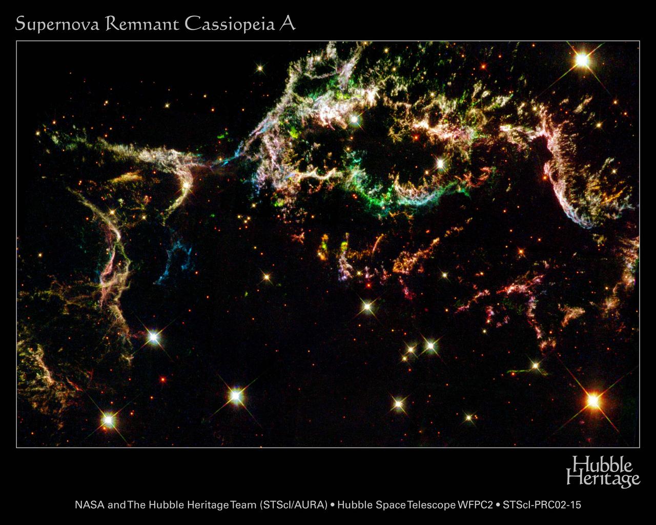
The colorful streamers that float across the sky in this photo taken by NASA's Hubble Space Telescope (HST) were created by the universe's biggest firecracker, the titanic supernova explosion of a massive star. The light from the exploding star reached Earth 320 years ago, nearly a century before the United States celebrated its birth with a bang. The dead star's shredded remains are called Cassiopeia A, or "Cas A" for short. Cas A is the youngest known supernova remnant in our Milky Way Galaxy and resides 10,000 light-years away in the constellation Cassiopeia, so the star actually blew up 10,000 years before the light reached Earth in the late 1600s. This HST image of Cas A shows for the first time that the debris is arranged into thousands of small, cooling knots of gas. This material eventually will be recycled into building new generations of stars and planets. Our own Sun and planets are constructed from the debris of supernovae that exploded billions of years ago. This photo shows the upper rim of the super nova remnant's expanding shell. Near the top of the image are dozens of tiny clumps of matter. Each small clump, originally just a small fragment of the star, is tens of times larger than the diameter of our solar system. The colors highlight parts of the debris where chemical elements are glowing. The dark blue fragments, for example, are richest in oxygen; the red material is rich in sulfur. The images were taken with the Wide Field and Planetary Camera 2 in January 2000 and January 2002. Image Credit: NASA and HST team (Stoics/AURA). Acknowledgment: R. Fesen (Darmouth) and J. Morse ( Univ. of Colorado).

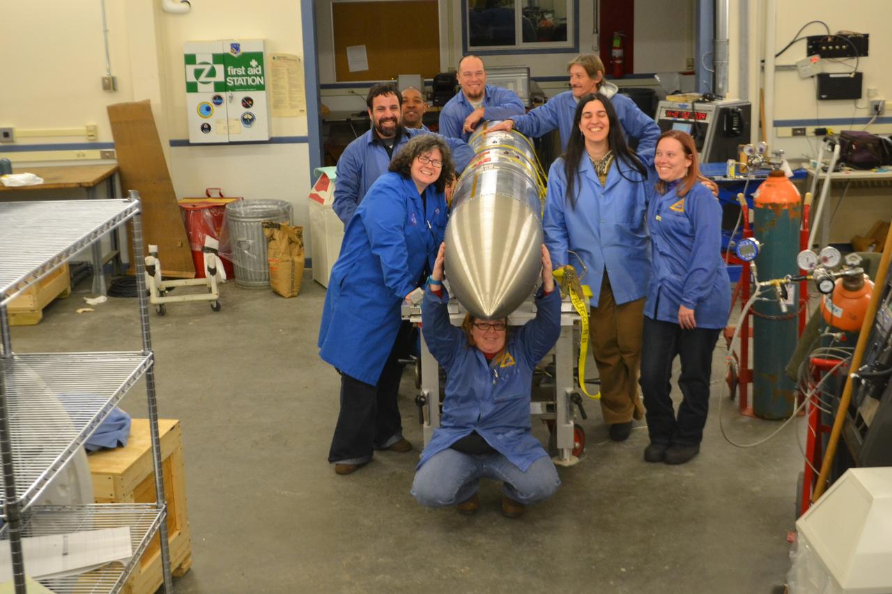
Caption: A NASA-funded sounding rocket launches into an aurora in the early morning of March 3, 2014, over Venetie, Alaska. The GREECE mission studies how certain structures – classic curls like swirls of cream in coffee -- form in the aurora. Credit: NASA/Christopher Perry More info: On March 3, 2014, at 6:09 a.m. EST, a NASA-funded sounding rocket launched straight into an aurora over Venetie, Alaska. The Ground-to-Rocket Electrodynamics – Electron Correlative Experiment, or GREECE, sounding rocket mission, which launched from Poker Flat Research Range in Poker Flat, Alaska, will study classic curls in the aurora in the night sky. The GREECE instruments travel on a sounding rocket that launches for a ten-minute ride right through the heart of the aurora reaching its zenith over the native village of Venetie, Alaska. To study the curl structures, GREECE consists of two parts: ground-based imagers located in Venetie to track the aurora from the ground and the rocket to take measurements from the middle of the aurora itself. At their simplest, auroras are caused when particles from the sun funnel over to Earth's night side, generate electric currents, and trigger a shower of particles that strike oxygen and nitrogen some 60 to 200 miles up in Earth's atmosphere, releasing a flash of light. But the details are always more complicated, of course. Researchers wish to understand the aurora, and movement of plasma in general, at much smaller scales including such things as how different structures are formed there. This is a piece of information, which in turn, helps paint a picture of the sun-Earth connection and how energy and particles from the sun interact with Earth's own magnetic system, the magnetosphere. GREECE is a collaborative effort between SWRI, which developed particle instruments and the ground-based imaging, and the University of California, Berkeley, measuring the electric and magnetic fields. The launch is supported by a sounding rocket team from NASA’s Wallops Flight Facility, Wallops Island, Va. The Poker Flat Research Range is operated by the University of Alaska, Fairbanks. “The conditions were optimal,” said Marilia Samara, principal investigator for the mission at Southwest Research Institute in San Antonio, Texas. “We can’t wait to dig into the data.” For more information on the GREECE mission visit: <a href="http://www.nasa.gov/content/goddard/nasa-funded-sounding-rocket-to-catch-aurora-in-the-act/." rel="nofollow">www.nasa.gov/content/goddard/nasa-funded-sounding-rocket- </a>.<b><a href="http://www.nasa.gov/audience/formedia/features/MP_Photo_Guidelines.html" rel="nofollow">NASA image use policy.</a></b> <b><a href="http://www.nasa.gov/centers/goddard/home/index.html" rel="nofollow">NASA Goddard Space Flight Center</a></b> enables NASA’s mission through four scientific endeavors: Earth Science, Heliophysics, Solar System Exploration, and Astrophysics. Goddard plays a leading role in NASA’s accomplishments by contributing compelling scientific knowledge to advance the Agency’s mission. <b>Follow us on <a href="http://twitter.com/NASAGoddardPix" rel="nofollow">Twitter</a></b> <b>Like us on <a href="http://www.facebook.com/pages/Greenbelt-MD/NASA-Goddard/395013845897?ref=tsd" rel="nofollow">Facebook</a></b> <b>Find us on <a href="http://instagram.com/nasagoddard?vm=grid" rel="nofollow">Instagram</a></b>

Caption: A NASA-funded sounding rocket launches into an aurora in the early morning of March 3, 2014, over Venetie, Alaska. The GREECE mission studies how certain structures – classic curls like swirls of cream in coffee -- form in the aurora. Credit: NASA/Christopher Perry More info: On March 3, 2014, at 6:09 a.m. EST, a NASA-funded sounding rocket launched straight into an aurora over Venetie, Alaska. The Ground-to-Rocket Electrodynamics – Electron Correlative Experiment, or GREECE, sounding rocket mission, which launched from Poker Flat Research Range in Poker Flat, Alaska, will study classic curls in the aurora in the night sky. The GREECE instruments travel on a sounding rocket that launches for a ten-minute ride right through the heart of the aurora reaching its zenith over the native village of Venetie, Alaska. To study the curl structures, GREECE consists of two parts: ground-based imagers located in Venetie to track the aurora from the ground and the rocket to take measurements from the middle of the aurora itself. At their simplest, auroras are caused when particles from the sun funnel over to Earth's night side, generate electric currents, and trigger a shower of particles that strike oxygen and nitrogen some 60 to 200 miles up in Earth's atmosphere, releasing a flash of light. But the details are always more complicated, of course. Researchers wish to understand the aurora, and movement of plasma in general, at much smaller scales including such things as how different structures are formed there. This is a piece of information, which in turn, helps paint a picture of the sun-Earth connection and how energy and particles from the sun interact with Earth's own magnetic system, the magnetosphere. GREECE is a collaborative effort between SWRI, which developed particle instruments and the ground-based imaging, and the University of California, Berkeley, measuring the electric and magnetic fields. The launch is supported by a sounding rocket team from NASA’s Wallops Flight Facility, Wallops Island, Va. The Poker Flat Research Range is operated by the University of Alaska, Fairbanks. “The conditions were optimal,” said Marilia Samara, principal investigator for the mission at Southwest Research Institute in San Antonio, Texas. “We can’t wait to dig into the data.” For more information on the GREECE mission visit: <a href="http://www.nasa.gov/content/goddard/nasa-funded-sounding-rocket-to-catch-aurora-in-the-act/." rel="nofollow">www.nasa.gov/content/goddard/nasa-funded-sounding-rocket- </a>.<b><a href="http://www.nasa.gov/audience/formedia/features/MP_Photo_Guidelines.html" rel="nofollow">NASA image use policy.</a></b> <b><a href="http://www.nasa.gov/centers/goddard/home/index.html" rel="nofollow">NASA Goddard Space Flight Center</a></b> enables NASA’s mission through four scientific endeavors: Earth Science, Heliophysics, Solar System Exploration, and Astrophysics. Goddard plays a leading role in NASA’s accomplishments by contributing compelling scientific knowledge to advance the Agency’s mission. <b>Follow us on <a href="http://twitter.com/NASAGoddardPix" rel="nofollow">Twitter</a></b> <b>Like us on <a href="http://www.facebook.com/pages/Greenbelt-MD/NASA-Goddard/395013845897?ref=tsd" rel="nofollow">Facebook</a></b> <b>Find us on <a href="http://instagram.com/nasagoddard?vm=grid" rel="nofollow">Instagram</a></b>

Caption: A NASA-funded sounding rocket launches into an aurora in the early morning of March 3, 2014, over Venetie, Alaska. The GREECE mission studies how certain structures – classic curls like swirls of cream in coffee -- form in the aurora. Credit: NASA/Christopher Perry More info: On March 3, 2014, at 6:09 a.m. EST, a NASA-funded sounding rocket launched straight into an aurora over Venetie, Alaska. The Ground-to-Rocket Electrodynamics – Electron Correlative Experiment, or GREECE, sounding rocket mission, which launched from Poker Flat Research Range in Poker Flat, Alaska, will study classic curls in the aurora in the night sky. The GREECE instruments travel on a sounding rocket that launches for a ten-minute ride right through the heart of the aurora reaching its zenith over the native village of Venetie, Alaska. To study the curl structures, GREECE consists of two parts: ground-based imagers located in Venetie to track the aurora from the ground and the rocket to take measurements from the middle of the aurora itself. At their simplest, auroras are caused when particles from the sun funnel over to Earth's night side, generate electric currents, and trigger a shower of particles that strike oxygen and nitrogen some 60 to 200 miles up in Earth's atmosphere, releasing a flash of light. But the details are always more complicated, of course. Researchers wish to understand the aurora, and movement of plasma in general, at much smaller scales including such things as how different structures are formed there. This is a piece of information, which in turn, helps paint a picture of the sun-Earth connection and how energy and particles from the sun interact with Earth's own magnetic system, the magnetosphere. GREECE is a collaborative effort between SWRI, which developed particle instruments and the ground-based imaging, and the University of California, Berkeley, measuring the electric and magnetic fields. The launch is supported by a sounding rocket team from NASA’s Wallops Flight Facility, Wallops Island, Va. The Poker Flat Research Range is operated by the University of Alaska, Fairbanks. “The conditions were optimal,” said Marilia Samara, principal investigator for the mission at Southwest Research Institute in San Antonio, Texas. “We can’t wait to dig into the data.” For more information on the GREECE mission visit: <a href="http://www.nasa.gov/content/goddard/nasa-funded-sounding-rocket-to-catch-aurora-in-the-act/." rel="nofollow">www.nasa.gov/content/goddard/nasa-funded-sounding-rocket- </a>.<b><a href="http://www.nasa.gov/audience/formedia/features/MP_Photo_Guidelines.html" rel="nofollow">NASA image use policy.</a></b> <b><a href="http://www.nasa.gov/centers/goddard/home/index.html" rel="nofollow">NASA Goddard Space Flight Center</a></b> enables NASA’s mission through four scientific endeavors: Earth Science, Heliophysics, Solar System Exploration, and Astrophysics. Goddard plays a leading role in NASA’s accomplishments by contributing compelling scientific knowledge to advance the Agency’s mission. <b>Follow us on <a href="http://twitter.com/NASAGoddardPix" rel="nofollow">Twitter</a></b> <b>Like us on <a href="http://www.facebook.com/pages/Greenbelt-MD/NASA-Goddard/395013845897?ref=tsd" rel="nofollow">Facebook</a></b> <b>Find us on <a href="http://instagram.com/nasagoddard?vm=grid" rel="nofollow">Instagram</a></b>

Caption: A NASA-funded sounding rocket launches into an aurora in the early morning of March 3, 2014, over Venetie, Alaska. The GREECE mission studies how certain structures – classic curls like swirls of cream in coffee -- form in the aurora. Credit: NASA/Christopher Perry More info: On March 3, 2014, at 6:09 a.m. EST, a NASA-funded sounding rocket launched straight into an aurora over Venetie, Alaska. The Ground-to-Rocket Electrodynamics – Electron Correlative Experiment, or GREECE, sounding rocket mission, which launched from Poker Flat Research Range in Poker Flat, Alaska, will study classic curls in the aurora in the night sky. The GREECE instruments travel on a sounding rocket that launches for a ten-minute ride right through the heart of the aurora reaching its zenith over the native village of Venetie, Alaska. To study the curl structures, GREECE consists of two parts: ground-based imagers located in Venetie to track the aurora from the ground and the rocket to take measurements from the middle of the aurora itself. At their simplest, auroras are caused when particles from the sun funnel over to Earth's night side, generate electric currents, and trigger a shower of particles that strike oxygen and nitrogen some 60 to 200 miles up in Earth's atmosphere, releasing a flash of light. But the details are always more complicated, of course. Researchers wish to understand the aurora, and movement of plasma in general, at much smaller scales including such things as how different structures are formed there. This is a piece of information, which in turn, helps paint a picture of the sun-Earth connection and how energy and particles from the sun interact with Earth's own magnetic system, the magnetosphere. GREECE is a collaborative effort between SWRI, which developed particle instruments and the ground-based imaging, and the University of California, Berkeley, measuring the electric and magnetic fields. The launch is supported by a sounding rocket team from NASA’s Wallops Flight Facility, Wallops Island, Va. The Poker Flat Research Range is operated by the University of Alaska, Fairbanks. “The conditions were optimal,” said Marilia Samara, principal investigator for the mission at Southwest Research Institute in San Antonio, Texas. “We can’t wait to dig into the data.” For more information on the GREECE mission visit: <a href="http://www.nasa.gov/content/goddard/nasa-funded-sounding-rocket-to-catch-aurora-in-the-act/." rel="nofollow">www.nasa.gov/content/goddard/nasa-funded-sounding-rocket- </a>.<b><a href="http://www.nasa.gov/audience/formedia/features/MP_Photo_Guidelines.html" rel="nofollow">NASA image use policy.</a></b> <b><a href="http://www.nasa.gov/centers/goddard/home/index.html" rel="nofollow">NASA Goddard Space Flight Center</a></b> enables NASA’s mission through four scientific endeavors: Earth Science, Heliophysics, Solar System Exploration, and Astrophysics. Goddard plays a leading role in NASA’s accomplishments by contributing compelling scientific knowledge to advance the Agency’s mission. <b>Follow us on <a href="http://twitter.com/NASAGoddardPix" rel="nofollow">Twitter</a></b> <b>Like us on <a href="http://www.facebook.com/pages/Greenbelt-MD/NASA-Goddard/395013845897?ref=tsd" rel="nofollow">Facebook</a></b> <b>Find us on <a href="http://instagram.com/nasagoddard?vm=grid" rel="nofollow">Instagram</a></b>

Caption: A NASA-funded sounding rocket launches into an aurora in the early morning of March 3, 2014, over Venetie, Alaska. The GREECE mission studies how certain structures – classic curls like swirls of cream in coffee -- form in the aurora. Credit: NASA/Christopher Perry More info: On March 3, 2014, at 6:09 a.m. EST, a NASA-funded sounding rocket launched straight into an aurora over Venetie, Alaska. The Ground-to-Rocket Electrodynamics – Electron Correlative Experiment, or GREECE, sounding rocket mission, which launched from Poker Flat Research Range in Poker Flat, Alaska, will study classic curls in the aurora in the night sky. The GREECE instruments travel on a sounding rocket that launches for a ten-minute ride right through the heart of the aurora reaching its zenith over the native village of Venetie, Alaska. To study the curl structures, GREECE consists of two parts: ground-based imagers located in Venetie to track the aurora from the ground and the rocket to take measurements from the middle of the aurora itself. At their simplest, auroras are caused when particles from the sun funnel over to Earth's night side, generate electric currents, and trigger a shower of particles that strike oxygen and nitrogen some 60 to 200 miles up in Earth's atmosphere, releasing a flash of light. But the details are always more complicated, of course. Researchers wish to understand the aurora, and movement of plasma in general, at much smaller scales including such things as how different structures are formed there. This is a piece of information, which in turn, helps paint a picture of the sun-Earth connection and how energy and particles from the sun interact with Earth's own magnetic system, the magnetosphere. GREECE is a collaborative effort between SWRI, which developed particle instruments and the ground-based imaging, and the University of California, Berkeley, measuring the electric and magnetic fields. The launch is supported by a sounding rocket team from NASA’s Wallops Flight Facility, Wallops Island, Va. The Poker Flat Research Range is operated by the University of Alaska, Fairbanks. “The conditions were optimal,” said Marilia Samara, principal investigator for the mission at Southwest Research Institute in San Antonio, Texas. “We can’t wait to dig into the data.” For more information on the GREECE mission visit: <a href="http://www.nasa.gov/content/goddard/nasa-funded-sounding-rocket-to-catch-aurora-in-the-act/." rel="nofollow">www.nasa.gov/content/goddard/nasa-funded-sounding-rocket- </a>.<b><a href="http://www.nasa.gov/audience/formedia/features/MP_Photo_Guidelines.html" rel="nofollow">NASA image use policy.</a></b> <b><a href="http://www.nasa.gov/centers/goddard/home/index.html" rel="nofollow">NASA Goddard Space Flight Center</a></b> enables NASA’s mission through four scientific endeavors: Earth Science, Heliophysics, Solar System Exploration, and Astrophysics. Goddard plays a leading role in NASA’s accomplishments by contributing compelling scientific knowledge to advance the Agency’s mission. <b>Follow us on <a href="http://twitter.com/NASAGoddardPix" rel="nofollow">Twitter</a></b> <b>Like us on <a href="http://www.facebook.com/pages/Greenbelt-MD/NASA-Goddard/395013845897?ref=tsd" rel="nofollow">Facebook</a></b> <b>Find us on <a href="http://instagram.com/nasagoddard?vm=grid" rel="nofollow">Instagram</a></b>
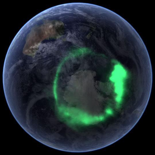
NASA file image acquired September 11, 2005 <b>To view a video of this event go here: <a href="http://www.flickr.com/photos/gsfc/6257608714">www.flickr.com/photos/gsfc/6257608714</a></b> From space, the aurora is a crown of light that circles each of Earth’s poles. The IMAGE satellite captured this view of the aurora australis (southern lights) on September 11, 2005, four days after a record-setting solar flare sent plasma—an ionized gas of protons and electrons—flying towards the Earth. The ring of light that the solar storm generated over Antarctica glows green in the ultraviolet part of the spectrum, shown in this image. The IMAGE observations of the aurora are overlaid onto NASA’s satellite-based Blue Marble image. From the Earth’s surface, the ring would appear as a curtain of light shimmering across the night sky. Like all solar storms, the September storm distorted the shape of the magnetic field that surrounds the Earth. Without buffeting from the solar wind (charged particles like protons and electrons that are ejected from the Sun), the Earth’s magnetic field would look something like a plump doughnut, with the North and South poles forming the slender hole in the center. In reality, the nearly constant solar winds flatten the space side of the “doughnut” into a long tail. The amount of distortion changes when solar storms, such as the flare on September 7, send stronger winds towards the Earth. Changes to the magnetic field release fast-moving particles, which flow with charged particles from the Sun towards the center of the “doughnut” at the Earth’s poles. As the particles sink into the atmosphere, they collide with oxygen and nitrogen, lighting the sky with Nature’s version of neon lights, the aurora. Though scientists knew that the aurora were caused by charged particles from the Sun and their interaction with the Earth’s magnetic field, they had no way to measure the interaction until NASA launched the Imager for Magnetopause-to-Aurora Global Exploration (IMAGE) satellite in 2000. The satellite’s mission was to collect data that would allow scientists to study the structure and dynamics of the Earth’s magnetic field for the first time. Designed to operate for two years, IMAGE sent its last data to Earth in December 2005 after a highly successful five-year mission. Since 2000, IMAGE has provided insight into how the Earth’s powerful magnetic field protects the planet from solar winds. Without the shield the magnetic field provides, the upper atmosphere would evaporate into space under the influence of solar winds. IMAGE has shown scientists what sort of changes the magnetic field undertakes as it diverts solar winds from the Earth. For a summary of the discoveries that IMAGE has made possible, see IMAGE Discovers. Instrument: IMAGE Credit: <a href="http://svs.gsfc.nasa.gov/index.html" rel="nofollow">NASA/Goddard Space Flight Center Scientific Visualization Studio</a> <b><a href="http://www.nasa.gov/audience/formedia/features/MP_Photo_Guidelines.html" rel="nofollow">NASA image use policy.</a></b> <b><a href="http://www.nasa.gov/centers/goddard/home/index.html" rel="nofollow">NASA Goddard Space Flight Center</a></b> enables NASA’s mission through four scientific endeavors: Earth Science, Heliophysics, Solar System Exploration, and Astrophysics. Goddard plays a leading role in NASA’s accomplishments by contributing compelling scientific knowledge to advance the Agency’s mission. <b>Follow us on <a href="http://twitter.com/NASAGoddardPix" rel="nofollow">Twitter</a></b> <b>Like us on <a href="http://www.facebook.com/pages/Greenbelt-MD/NASA-Goddard/395013845897?ref=tsd" rel="nofollow">Facebook</a></b> <b>Find us on <a href="http://instagrid.me/nasagoddard/?vm=grid" rel="nofollow">Instagram</a></b>